1
OWNER'S
MANUAL
MODELNOS°
247.795860
247=795861
Caution:
ReadandFollow
All SafetyRules
andInstructions
BeforeOperating
ThisEquipment
8 HORSEPOWER
3 CUTTING STAGE
MULCHING AND BAGGING
CHIPPER=SHREDDER
Assembly
Operation
CustomerResponsibilities
Serviceand Adjustment
Repair Parts
SEARS,ROEBUCKAND CO., HoffmanEstates, IL 60195 U.S.A.
Printed in U.S.A.
770_8175H
9/92
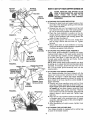
SAFETY RULES
l_
WARNING: TO REDUCE THE POTENTIAL FOR ANY INJURY, COMPLY WITH THE FOLLOWING
SAFETY INSTRUCTIONS. FAILURE TO COMPLY WITH THE INSTRUCTIONS MAY RESULT IN
PERSONAL INJURY,
o if the cutting mechanism strikes any foreign object or
your machine should start making an unusual noise or
vibration, immediately stop the engine, disconnect the
spark plug wire from the spark plug and move it away
from the spark plug Allow the machine to stop and take
the following steps:
Inspect for damage
Replace or repair any damaged parts
Check for any loose parts and tighten to assure continued safe operation
e The engine must be kept clean of debris and other accumulations.
e Do not allow an accumulation of processed material to
build up in the discharge area as this will prevent proper
discharge and can result in kick-back from feed opening
e Never place your hands or any other part of your body or
clothing inside the feeding chamber, discharge chute or
near any moving part while the engine is running
e Keep all guards and deflectors in place and in good working condition to assure continued safe operation
e Always stand clear of the discharge area when opelating
this machine
e Keep your face and body back from the feed opening to
avoid accidental bounce back of any material.
® Do not over-reach Keep proper balance and footing at all
times
e The engine governor settings on your machine must not
be altered, changed, or tampered with The governor
contrels the maximum safe operating speeds and protects the engine and all moving parts from damage
caused by overspeed.
e Do not transport machine while engine is running
e Do not operate engine if air cleaner or cover directly over
carburetor air intake is removed, except for adjustment.
Removal of such parts could create a fire hazard
TRAINING
e Read this owner's manual carefully in its entirety before
attempting to assemble or operate this machine Be completely familiar with the controls and the proper use of this
machine before operating it Keep this manual in a safe
place for future and regular reference and for ordering
replacement parts
e Children must never be allowed to operate this equipment
e No one should operate this unit while intoxicated or while
taking medication that impairs the senses or reactions
e This equipment should never be operated in the vicinity
of children, pets or other persons
® Never run your machine in an enclosed area as the
exi_aust from the engine contains carbon monoxide, which
is an odorless, tasteless and deadly poisonous gas
e Never place your hands or any part of your body or clothing inside the feeding chamber, discharge chute, or near
any moving part while the machine or engine is running.
e If it is necessary for any reason to inspect or repair the
feeding chamber or any part of the machine where a moving part can come in contact with your body or clothing,
stop the machine, allow it to cool, disconnect the spark
plug wire from the spark plug and move it away from the
spark plug before attempting such inspection or repair
PREPARATION
e Wear safety glasses provided with your unit while operating the chipper-shredder to prevent injury from any material which may be ejected out of the openings.
e Wear proper apparel Avoid wearing loose fitting clothing
Wear gloves when handling material
e HANDLE GASOLINE WITH CARE as it is an extremely
flammable fuel
o Check the fuel before starting the engine Do not fill the
fuel tank indoors, while the engine is running, or while the
engine is still hot Turn the unit off and let the engine cool
before refueling
o Fuel your chipper-shredder
in a clean area Do not
smoke while refueling
• Fuel tank cap must be secure at all times except dudng
refueling
® Avoid spilling gasoline or oil Wipe the unit clean of any
spilled fuel or oil.
® Store fuel and oil in approved containers, away from heat
or open flame, and out of reach of children
• This machine should be operated only upon a level surface
® Assure that all screws, nuts and bolts and other fasteners
are properly secured
MAINTENANCE AND STORAGE
o When this equipment is stopped for servicing, inspection,
storage or to change an accessory, make sure the spark
plug wire is disconnected from the spark plug and moved
away from the spark plug The machine should be
allowed to cool down before making such inspection,
adjustments, service, etc Maintain your machine with
care and keep it clean for the best and continued safe
operation
o De not use flammable solutions to clean the air filter
O When not in use, your machine should be stored out of
the reach of children. Keep where gasoline fumes will not
reach an open flame or spark For long periods of storage, refer to the "Storage" section of this manual.
OPERATION
® When feeding shreddable material into this equipment,
be extremely careful that pieces of metal, rocks, bottles,
cans or other foreign objects are not included Personal
injury or damage to the machine could result
I
LOOK FOR THIS SYMBOL TO POINT OUT]
IMPORTANT SAFETY PRECAUTIONS. ITI
MEANS--ATTENTION!!! BECOMEALERT!!!
YOURSAFETY S NVOLVED.
/
J
2
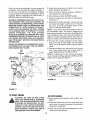
CC'NGRATULATIONS
on your purchase of a Sears
Crattsman Chipper-Shredder
It has been designed, engineered and manufactured
to give you the best possible
dependability and performance,
Should you experience any problem you cannot easily remedy, please contact your nearest Sears Service Center/
Department in the United States, We have competent, welltrained technicians and the proper tools to service or repair
this unit
Please read and retain this manual The instructions will
enable you to assemble and maintain your chipper-shredder
properly Always observe the "SAFETY RULES"
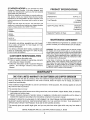
PRODUCT SPECnFICATIONS
Horsepower:
&0
Displacement:
19,44 cu in
Fuel Capacity:
1 Gallon
(Unleaded)
Spark Plug (Gap 030 in.):
Champion
J19LM (or
Equivalent)
MODEL
NUMBER
Magnetron ® Ignition Air Gap:
SERIAL
NUMBER
DATE OF
PURCHASE
MAINTENANCE
,0125 in
AGREEMENT
THE MODEL AND SERIAL NUMBERS WILL BE FOUND
ON A LABEL ATTACHED TO THE FRAME OF THE
CHIPPER-SHREDDER
A Sears Maintenance Agreement is available on this
product Contact your nearest Sears store for details
YOU SHOULD RECORD BOTH SERIAL NUMBER AND
DATE OF PURCHASE AND KEEP IN A SAFE PLACE
FOR FUTURE REFERENCE
WARNING: This unit is equipped with an internal combustion engine and should not be used on or near any unimproved forest-covered, brush-covered or grass-covered land
unless the engine's exhaust system is equipped with a
spark arrester meeting applicable local or state laws (if any)
If a spark arrester is used, it should be maintained in effective working order by the operator
CUSTOMER
RESPONSIBILITIES
e Read and observe the safety rules,
e Follow a regular schedule in maintaining, caring for
and using your chipper-shredder,
® Follow the instructions under "Customer Responsibilities"
and "Storage" sections of this Owner's
Manual
in the State of California the above is required by law
(Section 4442 of the California Public Resources Code)
Other states may have similar laws, Federal laws apply on
federal lands A spark arrester for the muffler is availabte
through your nearest Sears Authorized Service Center (See
the REPAIR PARTS section of this manual)
WARRANTY
ONEYEARLIMITEDWARRANTYOH CRAFTSMANGASCHIPPER-SHREDDER
For one year from the date of purchase, when this Craftsman Chipper-Shredder is maintained, lubricated and
tuned up according to the instructions in the owner's manual, Sears will repair, free of charge, any defect in
material and workmanship
If this Craftsman Chipper-Shredder
days from the date of purchase.
is used for commercial
or rental purposes, this warranty applies for only 30
This warranty does not cover:
® Expendable items which become worn during normal use, such as blades, chipper blades, flails, air cleaners,
spark plugs and catcher bags
e Repairs necessary because of operator abuse or negligence, including bent crankshafts and the failure to
maintain the equipment according to the instructions contained in the owner's manual,
WARRANTY SERVICE IS AVAILABLE BY RETURNING THE CRAFTSMAN CHIPPER-SHREDDER TO THE
NEAREST SEARS SERVICE CENTER/DEPARTMENT
IN THE UNITED STATES THIS WARRANTY
APPLIES ONLY WHILE THIS PRODUCT IS IN USE iN THE UNITED STATES
This warranty gives you specific legal rights, and you may also have other rights which may vary from state to
state.
SEARS, ROEBUCK AND CO. D/817WA, Hoffman Estates, IL 60195
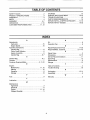
TABLE OF CONTENTS
'
STORAGE .............................................................................
13
SAFETY RULES .......................................................................
2
SERVICE AND ADJUSTMENT ..............................13-15
PRODUCT SPECIFICATIONS ..................................... 3
TROUBLE SHOOTING ...........................................................
16
WARRANTY .........................................................................................
3
PARTS ORDERING/SERVICE ......................................16
INDEX .........................................................................................
4
REPAIR PARTS--CHIPPER-SHREDDER
........ 17, 18
ASSEMBLY ....................................................................5-7
REPAIR PARTS--ENGINE ......................................19-23
OPERATION .....................................................................
7-10
CUSTOMER RESPONSIBILITIES
..........................
11, 12
HNDEX
A
O
Oil ..............................................................................................
9
Adjustments:
Carburetor .................................................................................
15
Operating Tips .................................................................................
8
R
Engine Speed ...................................................................
15
Assembly Instructions:
Repair/Replacement Parts .........................................
17-23
Catcher Bag .............................................................................
6
Responsibilities, Customer .....................................
3, 11-13
Chute Crank Deflector ............................................................
6
S
Hopper Assembly ....................................................... 6
Safety Rules .................................................................... 2
Catcher Bag .......................................................
6, 7
Sharpening .....................................................................
14, 15
C
Service Recommendations ..............................................
11
Catcher Bag ...................................................................6, 7
Spark Plug .......................................................................12
Controls .......................................................................... 7
Specifications ......................................................................
3
Customer Responsibilities ................................ 3, 11,12
Storage ......................................................................................
13
E
T
Engine:
Table of Contents ..............................................................4
Maintenance ...................................................
11, 12
Trouble Shooting ...............................................................
16
U
Starting ..............................................................................
10
Stopping .................................................................................
8
Unclogging ............................................................... 13, 14
Storage ...................................................................................
13
Unpacking ......................................................................................
5
F
W
Fuel ......................................................................................................
9
Warranty .......................................................................... 3
L
Lubrication ...............................................................
11
M
Maintenance:
Agreement .......................................................................................
3
Schedule .........................................................
11
Engine .......................................................................
11, 12
Chipper-Shredder .........................................................................
11
4
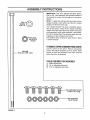
ASSEMBLY mNSTRUCTmONS
£
IMPORTANT: This unit is shipped WITHOUT GASO_
LINE or OIL After assembly, see operation section of
this manual for proper fuel and engine oil recommendation&
NOTE: To determine right and left hand sides of your
chipper-shredder, stand behind and face the hopper
...Fla.t-"_/'-,f'_'_
5_l_Sl]el_ k_,,,.._)
• __
I
II
(engine is at the front of the unit)
Your chipper-shredder has been completely assembled at the factory, except for the hopper assembly
I
I
!
I
I_
II
]_
tl
I]
II
(hopper hood and upper leaf ramp section have been
sub-assembled), upper guide assembly, chute deflector and the catcher bag The hardware pack and safety glasses are also included in the carton
The hardware pack contains the parts shown in figure
1 (shown full size)
1
._
[/_._'_]-<'-Hex
Lock
[l_..)))1
Nut 5/16-18
_
Thread
b il
TOREMOVE
CHIPPER-SHREDDER
FROMCARTON
I
I
!l
II
I 11----5110-1_e'.-%1°.
:'Loog
Cut the corners of the carton Remove all packing
inserts Roll chipper-shredder out of the carton Make
certain all parts and literature have been removed
I
!J
before the carton is discarded
.....
I II
TOOLS REQUIREDFOR ASSEMBLY
I II
I II
I
/
I i
IL
FIGURE 1.
(1) Phillips
Screwdriver
(2)1/2"or
Adjustable Wrenches
(2) 7/16 or Adjustable Wrenches
I__
M
[]
[]
I_-
TrusoM°chi°eScrew
.e LockNu,a
HOWTOSET-UPYOURCHIPPER-SHREDCER
Housing
Assembly
Spacers
MAKE CERTAIN
THE SPARK
PLUG
WIRE IS DISCONNECTED
AND MOVED
AWAY
FROM
THE
SPARK
PLUG
BEFORE ASSEMBLING THE CHIPPERSHREDDER.
Hinge)
Chute
Deflector
Hex LockNut
Hand
FIGURE 2.
Stop
Washer
Upper
Guide
Release
Bar
Assembly
8-3/8" Long
Flat Washer
Hex Lock Nut
Frame
FIGURE 3.
Hopper Pivot
Door
ASSEMBLE THIS
TRUSS SCREW
AND NUT FIRST
Hopl:
pper
Leaf
Ramp
Section
Bar
Jper
Guide
Assembly
FIGURE 4.
Assembly
Remove Truss
Screw and Nut
, Drawstring
./
'Plunger
FIGURE 5.
_-A'I-rACHING
THE CHUTE DEFLECTOR
e Remove the hand knobs and cupped washers from
each side of the discharge opening on the left side
of the chipper-shredder
e Remove hex lock nut, two spacers and hex bolt
from inside the hinge on top of the housing assembly Do not remove one spacer from the hex bolt
e Place the chute deflector in position on the discharge opening Insert hex bolt and spacer through
hinge on chute deflector and housing (spacer fits
inside of hinge). See figure 2.
® Place second spacer over hex bolt, inside other
part of hinge. Secure with hex lock nuL Tighten
securely.
e Secure both sides of chute deflector to housing
using hand knobs and cupped washers (cupped side
of washers go against chute deflector)
-<-ATTACHING THE UPPER GUIDE ASSEMBLY
Place upper guide assembly in position on frame,
making certain edges of the upper guide assembly
are underneath stop washers, and the release bar is
in the slots= See figure 3 Insert hex bolt 8-3/8" long
through upper guide assembly and frame Secure
with flat washer and hex lock nuL
NOTE: Make certain upper guide assembly can pivot
by pulling up on release bar and lowering upper guide
assembly If necessary, loosen hex lock nut a turn or
two Put the upper guide assembly back into the
raised position,
"_-ATTACHING THE HOPPER ASSEMBLY
Your chipper-shredder
has been shipped with the
upper leaf ramp section attached to the hopper
assembly See figure 4 Attach the hopper assembly
to the upper guide assembly as follows. Be certain to
place heads of all truss machine screws inside of
hopper assembly_
• Remove one truss machine screw and nut from
each side of hopper assembly as shown in figure 4.
Push hopper pivot door down inside lower part
of hopper as you place hopper assembly (both
pieces) inside upper guide assembly_ Replace
truss screws and nuts just removed, using the hole
shown in figure 4, one on each side Tighten finger
tight only
e Place the six truss machine screws and nuts found
in hardware pack in the remaining holes of hopper
assembly, alternating sides of the unit and tightening finger tight only
• After assembling all eight screws, tighten them
securely
<-ATTACHING
THE CATCHER BAG
Your chipper-shredder is equipped with a catcher bag
to catch the shredded material
6
e To attachthe bag,placethe
opening of the bag
over the chute deflector so it completely covers the
chute opening. Depress the plunger on the draw-
string, and pull on the drawstring until the bag is
tight around the chute opening. Release plunger to
lock it into position See figure 5,
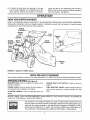
OPERATnON
KNOWYOURCHIPPER-SHREDDER
READ THIS OWNER'S MANUAL AND SAFETY RULES BEFORE OPERATING YOUR CHIPPER-SHREDDER_
Compare the illustrations with your chipper-shredder to familiarize yourself with the location of various controls
and adjustments Save this manual for future reference
Hopper
Assembl
Chipper
Chute
Fuel
Tank
Oil Fill
Dipstic
Release
Bar
Chute
Deflector
Engine
Switch
Choke
Lever.
Starter
Handle
Bag
FIGURE 6--Model
247.795861 Shown.
MEETSANSISAFETYSTANDARDS
Sears chipper-shredders
conform to the safety standard B71 6-1982 of the American National Standards Institute
OPERATING
CONTROLS(See
RELEASE BAR--Used
raising or lowering
CHOKE LEVER--Used
figure 6)
to release the hopper when
to enrich the fuel mixture in
the carburetor when starting a cold engine.
STARTER
engine,
HANDLE--Used
to manually
start the
ENGINE
engine.
SHUT-OFF
SWITCH--Used
to stop the
FUEL SHUT-OFF VALVE--Used
to stop the flow of
fuel into the carburetor (located beneath the fuel
tank)
BEFORE USING YOUR CHIPPER-SHREDDER,
AGAIN REFER TO THE "SAFETY
PAGE 2 OF THIS MANUAL ALWAYS BE CAREFUL,
RULES" AS SHOWN ON
The operation of any chipper-shredder can result in foreign objects being thrown into
the eyes, which can result in severe eye damage Always wear the safety glasses provided with the chipper-shredder or eye shields before chipping or shredding, or while
performing any adjustments or repairs. We recommend Wide Vision Safety Mask for
over spectacles or standard glasses available at Sears Retail or Catalog Stores
No Larger Than
1/2" Diameter
Recommended)
TO STOPENGINE
• Move engine shut-off switch to OFF position
figure 6
See
(Maximum)
• Disconnect spark plug wire and move away from
spark plug to prevent accidental starting while
equipment is unattended.
e Close fuel shut-off valve when equipment is not in
use to prevent fuel leakage.
\
Hopper
Assembly
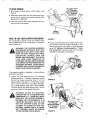
HOWTO USEYOURCHIPPER-SHREDDER
Do not attempt to shred or chip any material other
than vegetation found in a normal yard (i..e, branches,
leaves, twigs, etc.)
WARNING: THE CHIPPER-SHREDDER
DISCHARGES
MATERIALS WITH CONSIDERABLE
VELOCITY,
KEEP AWAY
FROM THE AREA AROUND THE CHUTE
DEFLECTOR,
ALWAYS
STOP THE
ENGINE AND DISCONNECT THE SPARK
PLUG WIRE WHEN REMOVING
OR
A'I-rACHING THE BAG WHEN CHANGING
CONTAINERS OR WHEN REMOVING THE
SHREDDED MATERIAL. WEAR SAFETY
GLASSES
AND GLOVES WHENEVER
USING YOUR CHIPPER-SHREDDER.
The chipper-shredder
methods of operation.
FIGURE 7.
® Leaves and small twigs can be raked into the hopper assembly when the hopper assembly is lowered to the ground. See figure 8 Small branches
up to 1/2" diameter (recommended)
or 1" diameter (maximum) can also be fed into the hopper
assembly in this position See figure 9
\
is designed for three different
e Leaves and small branches up to 1/2" diameter
(recommended) or 1" diameter (maximum) can be
fed into the hopper' assembly when it is in the
raised position. See figure 7 If it becomes necessary to push material into the chipper-shredder,
use a small diameter stick--NOT YOUR HANDS.
The stick should be small enough that it will be
ground up if gets into the impeller assembly
WARNING:
DO NOT PUT MATERIAL
LARGER THAN 1/2" IN DIAMETER (RECOMMENDED)
or 1" DIAMETER (MAXIMUM) INTO THE HOPPER ASSEMBLY.
MATERIAL UP TO A MAXIMUM OF 3" IN
DIAMETER
MATERIAL
MAY BE FED
INTO THE CHIPPER CHUTE. DO NOT
ATTEMPT
TO SHRED OR CHIP ANY
MATERIAL LARGER THAN 3" IN DIAMETERo PERSONAL INJURY OR DAMAGE
1"OTHE MACHINE COULD RESULT.
FIGURE 8.
No Larger Than
1/2" Diameter
(Recommended)
Or 1" Diameter
(Maximum)
FIGURE 9.
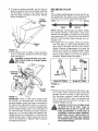
GASANDOIL FiLL-UP
® To lower the hopper assembly, use one hand to
grasp the handle at the top of the hopper assembly
and lift slightly Pull up on the release bar, and
lower the hopper assembly to the ground Release
the bar_ See figure 10
OIL
Only use high quality detergent oil rated with API service classification SG Select the oil's viscosity grade
according to your expected operating temperature.
Hopper
Colder
<_
32°F _
5W30
5/
_
Warmer
SAE 30
NOTE: Although multFviscosity oils (5W30, 10W30,
etc.) improve starting in cold weather, these multiviscosity oils will result in increased oil consumption
when used above 32°F. Check your oil level more fiequently to avoid possible engine damage from running low on oil
e Fill engine with oil as follows. Remove oil fill dipstick See figure 12 With chipper-shredder
level,
use a funnel to fill engine with oil to FULL mark on
dipstick. Capacity is approximately 2-3/4 pints. Be
careful not to overfill. Tilt chipper-shredder toward
the left (from behind the hopper), then re-level.
Check oil level Refill to FULL mark on dipstick if
necessary. Replace dipstick and tighten.
Bar
Release
FIGURE 10.
e Bulky material, such as stalks or heavy branches,
up to 3" in diameter, should be fed into the chipper
chute See figure 11
WARNING: MAKE CERTAIN THE CHIPPER CHUTE DOOR IS CLOSED WHEN
NOT IN USE.
Oil
Dipstick
Oil
Fill
Dipstick
3" Maximum
\
Model 247.795860
Model 247,795861
FIGURE 12,
GAS
ipper
Chute
e Remove fuel cap and fill fuel tank with about 1 gallon of clean, fresh, lead-free grade automotive
gasoline DO NOT use Ethyl or high octane gaso*
line. Be certain container is clean and free from
rust or foreign particles Never use gasoline that
may be stale from long periods of storage in the
container Replace fuel cap.
Oil
Drair
FIGURE 11.
IMPORTANT: There is a flail screen located inside
the housing in the discharge area If the flail screen
becomes clogged, remove and clean as instructed in
the Service and Adjustments section_ For best performance, it is important to keep the shredding blade
and the chipper blades sharp If the composition of
the material being discharged changes (becomes
stringy, etc) or if the rate at which the material is discharged slows down considerably, it is likely that the
shredding blade and/or chipper blades are dull and
need to be sharpened or replaced Refer to Service
and Adjustments section.
WARNING: DO NOT FILL CLOSER THAN
1/2 INCH OF TOP OF FUEL TANK TO
PREVENT SPILLS AND TO ALLOW FOR
FUEL EXPANSION.
IF GASOLINE
IS
ACCIDENTLY SPILLED, MOVE CHIPPERSHREDDER
AWAY FROM AREA OF
SPILL. AVOID CREATING ANY SOURCE
OF IGNITION UNTIL GASOLINE VAPORS
HAVE DISAPPEARED.
9
Check the fuel level periodically to avoid running out
of gasoline while operating the chipper-shredder.
If
the unit runs out of gas as it is shredding or chipping,
it may be necessary to unclog the unit before it can be
restarted. Refer to "Removing the Flail Screen" in
SERVICE AND ADJUSTMENT section
® Attach spark plug wire and rubber boot to spark
plug if necessary. See figure 13.
e Open fuel shut-oft valve by turning in direction of
arrow several turns. See figure 14
® Move choke lever down to CHOKE position
e Place the engine shut*off
See figure 14
WARNING: EXPERIENCE INDICATES THAT ALCOHOL BLENDED FUELS (CALLED GASOHOL OR
USING ETHANOL OR METHANOL) CAN ATTRACT
MOISTURE WHICH LEADS TO SEPARATION AND
FORMATION
OF ACIDS DURING STORAGE.
ACIDIC GAS CAN DAMAGE THE FUEL SYSTEM
OF AN ENGINE WHILE IN STORAGE. TO AVOID
ENGINE
PROBLEMS,
THE FUEL
SYSTEM
SHOULD BE EMPTIED OR TREATED WITH FUEL
STABILIZER
BEFORE STORAGE FOR 30 DAYS
OR LONGER. USE FRESH FUEL NEXT SEASON.
SEE "STORAGE"
SECTION FOR ADDITIONAL
INFORMATION.
switch in ON position
® Grasp starter handle (see figure 13) and pull rope
out slowly until engine reaches start of compression cycle (rope will pull slightly harder at this
point) Let the rope rewind slowly
NOTE: A noise will be heard when finding the start of
the compression cycle. This noise is caused by the
flails and fingers which are part of the shredding mechanism falling into place, and should be expected In
addition, the flails and finger's will be noisy after the
engine is started, until the impeller reaches full speed
e Pull rope with a rapid, continuous, full arm stroke
Keep a firm grip on start handle Let rope rewind
slowly. Do not let starter handle snap back against
starter
NEVER USE ENGINE OR CARBURETOR CLEANER PRODUCTS IN THE FUEL TANK OR PERMANENT DAMAGE MAY OCCUR.
e Repeat preceding two instructions until engine
fires. When engine starts, move choke lever on
engine halfway between CHOKE and RUN.
NOTE: If engine does not fire after three attempts,
move choke lever halfway between CHOKE and RUN
position and try again. See figure 14.
Spark Plug,
Wire and Boot
Muffler
To
."°o
\4
\\
Choke ""
Fuel Shut=Off
Valve
"
Choke Lever
Engine Shut-Off
Switch
FIGURE 14.
Starter
Handle
FIGURE 13.
TO STARTENGINE
_
TO STOPENGINE
WARNING:
BE SURE NO ONE OTHER
THAN THE OPERATOR
iS STANDING
NEAR THE CHIPPER-SHREDDER
WHILE
STARTING
OR OPERATING.
DO NOT
OPERATE THIS CHIPPER-SHREDDER
UNLESS THE CHUTE DEFLECTOR HAS
BEEN PROPERLY INSTALLED
AND IS
SECURED WITH THE HAND KNOBS.
e Move engine shut-oft switch to OFF position See
figure 14.
® Disconnect spark plug wire and move away from
spark plug to prevent accidental starting while
equipment is unattended
® Close fuel shut-off valve when equipment is not in
use to prevent fuel leakage.
10
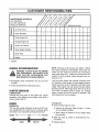
CUSTOMER
MAINTENANCE
SCHEDULE
RESPONSDBnLITIES
,/___//_O_/
.s
FILL IN DATES
/_
REGULAR SERVICE
!
,/
/
_/
_
/
/
,_/a,,o_/^_,co/
/
SERVICE
....... DATES
FOil
O
Pivot Points
_/
Clean Shredder
q
_1
rt
Check Engine Oil
_/
Change Engine Oil
z
_]
_/
Service Air Cleaner
_/
Clean Engine Cylinder
_/
_/
Spark Plug
"4
_/
Muffler
_/
_/ CHECK
GENERALRECOMMENDATIONS
NOTE: Although multi-viscosity oils (SE30, 10W30,
etc ) improve starting in cold weather, these multi- viscosity oils will result in increased oil consumption
when used above 32°F Check your oil level more frequently to avoid possible engine damage from running low on oil
WARNING: ALWAYS STOP THE ENGINE
AND DISCONNECT
THE SPARK PLUG
WIRE
BEFORE
PERFORMING
ANY
MAINTENANCE OR ADJUSTMENTS.
e Periodically
are tighL
check all fasteners
Your four-cycle engine will normally consume some
oil--therefore, check engine oil level regularly approximately every five hours of operation and before each
usage Stop engine and wait several minutes before
checking oil level. With engine level, the oil must be to
FULL mark on dipstick (refer to figure 12). Change
engine oil after the first five hours of operation, and
every twenty-five hours thereafter.
and be sure they
e Follow the Maintenance Schedule above
CHIPPER-SHREDDER
LLIBRICATION
Lubricate the pivot paints on the release bar, hopper
assembly, chute deflector and chipper chute once a
season using a light oil
ENGINE
To Drain Oil:
ENGINE OIL
e Drain oil while engine is warm
Only use high quality detergent oil rated with API service classification SG Select the oil's viscosity grade
according to your expected operating temperature
Colder
-._
32°F
a_ Remove oil drain plug Refer to figure 11. Catch
oil in a suitable container
b When engine is drained of all oil, replace drain
plug securely.
" Warmer
® Refill with fresh oil
UP section,
5W30
M
SAE 30
e Replace dipstick.
11
Refer to GAS AND OIL FILL-
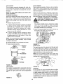
AIRCLEANER
The air cleanerpreventsdamagingdirt, dust,etc.,
fromenteringthe carburetorandbeingforcedintothe
engine and is important to engine life and performance
CLEAN ENGINE
Never run your engine without air cleaner completely assembled.
To Service Air' Cleaner:
Service pre-cleaner after every 25 hours of use, or at
least once a season. Service cartridge every 100
hours of use, or at least once a season. Service precleaner and cartridge more often under dusty conditions.
Yearly or every 25 hours, whichever occurs first,
remove the blower housing and clean the areas
shown in figure 17 to avoid overspeeding, overheating
and engine damage. Clean more often if necessary.
WARNING: PERIODICALLY CLEAN MUFFLER AREA TO REMOVE ALL GRASS,
DIRT AND COMBUSTIBLE DEBRIS.
nate the fuel system
LEANING
The chipper-shredder may be cleaned by running
water from a hose through the hopper assembly
and chipper chute with the engine running. Allow
the chipper-shredder to dry thoroughly.
e Remove wing nut and cover
To service foam pre-cleaner: Remove pre-cleaner
by sliding it off the cartridge Wash in liquid detergent and water. Squeeze dry in a clean cloth
Saturate
in engine oil. Squeeze
in a clean,
absorbent cloth to remove all excess oil If precleaner is very dirty, replace it..
@
'.
Clean engine periodically_ Remove dirt and debhs
with a cloth or brush. Cleaning with a forceful spray of
water is not recommended as water could contami-
e Wash the bag periodically with water. Allow to dry
thoroughly in the shade. Do not use heat.
To service cartridge: Remove cartridge by removing wing nut and lifting off cup and cartridge Clean
by tapping gently on a flat surface. If very dirty,
replace.. Do not oil cartridge
/I_[-_'F]I_-_
cha.
.._r_
_ CleanOut
and
NOTE: Do not use petroleum solvents leg. kerosene)
or pressurized air to clean cartridge They will cause
cartridge to deteriorate.
•
Reinstall cartridge, cup, pre-cleaner and cover'.
•
Fasten wing nuts securely.
FIGURE 17.
SPARK PLUG
The spark plug should be cleaned and the gap reset
to .030" at least once a season or' every 50 hours of
operation. See figure 18. Spark plug replacement is
recommended at the start of each season. Refer to
engine parts list for correct spark plug type.
Foam
=re-Cleaner
NOTE: Do not sandblast spark plug Spark plug
should be cleaned by scraping or wire brushing and
washing with a commercial solvent..
Wing Nut
.030" Feeler Gau
'Cup
FIGURE 15.
Plug
FUEL FILTER
FIGURE 18.
Your engine is equipped with a replaceable in-line fuel
filter. Replace the fuel filter every season. See figure
16 Refer to engine parts list for' correct replacement
filter,
MUFFLER
Do not operate the chipper-shredder without a muffler
or tamper' with the exhaust system Damaged mufflers
or spark arresters could create a fire hazard. Inspect
periodically, and replace if necessary. If your engine
is equipped with a spark arrester screen assembly,
remove every 50 hours for cleaning and inspection.
Replace if damaged.
FIGURE 16.
12
STORAGE
Prepare your chipper-shredder for storage at the end
of the season or if the unit will not be used for 30 days
or more.
® Drain the fuel tank
® Start the engine and let it run until the fuel lines and
carburetor are empty
e Never use engine or carburetor cleaner products in
the fuel tank or permanent damage may occur
e Use fresh fuel next season.
WITH FUEL IN THE FUEL TANK INSIDE
WARNING:
STORE
MACHINE
OF BUILDINGNEVER
WHERE
FUMES
MAY
REACH AN OPEN FLAME OR SPARK, OR
WHERE
IGNITION
SOURCES
ARE
PRESENT SUCH AS HOT WATER AND
SPACE HEATERS, FURNACES, CLOTHES
DRYERS, STOVES, ELECTRIC MOTORS,
ETC.
NOTE: Fuel stabilizer is an acceptable alternative in
minimizing the formation of fuel gum deposits during
storage. Add stabilizer to gasoline in fuel tank or storage container. Always follow the mix ratio found on
stabilizer container Run engine at least 10 minutes
after adding stabilizer to allow the stabilizer to reach
the carburetor. Do not drain the gas tank and carburetor if using fuel stabilizer
NOTE: A yearly check-up by your local Sears Service
Center is a good way to make certain your chippershredder will provide maximum performance for the
next season
e Drain all the oil from the crankcase (this should be
done after the engine has been operated and is still
warm) and refill the crankcase with fresh oil
CHIPPER-SHREDDER
e Clean the chipper-shredder
• If you have drained the fuel tank, protect the inside
of the engine as follows Remove spark plug, pour
approximately 1/2 ounce (approximately one tablespoon) of engine oil into cylinder and crank slowly
to distribute oil. Replace spark plug.
thoroughly.
® Wipe unit with an oiled rag to prevent rust (use a
light oil or silicone)
ENGINE
IMPORTANT:
IT IS IMPORTANT
TO PREVENT
GUM DEPOSITS FROM FORMING IN ESSENTIAL
FUEL SYSTEM PARTS SUCH AS CARBURETOR,
FUEL FILTER, FUEL HOSE, OR TANK DURING
STORAGE. ALSO, EXPERIENCE INDICATES THAT
ALCOHOL BLENDED FUELS (CALLED GASOHOL
OR USING ETHANOL
OR METHANOL)
CAN
ATTRACT MOISTURE WHICH LEADS TO SEPARATION AND FORMATION OF ACIDS DURING STORAGE. ACIDIC GAS CAN DAMAGE THE FUEL SYSTEM OF AN ENGINE WHILE IN STORAGE
OTHER
e Do not store gasoline from one season to another
® Replace your gasoline can if your can starts to rust
Rust and/or dirt in your gasoline will cause problems
e Store unit in a clean, dry area Do not store next to
corrosive materials, such as fertilizer
NOTE: If storing in an unventilated or metal storage
shed, be certain to rustproof the equipment by coating
with a light oil or silicone.
SERVRCE & ADJUSTMENT
WARNING: ALWAYS STOP ENGINE AND
DISCONNECT SPARK PLUG WIRE AND
MOVE IT AWAY FROM SPARK PLUG
BEFORE PERFORMING
ANY ADJUST T
MENTS OR REPAIRS.
O
Loosen the two hand knobs on each side of the
chute deflector. Lift the chute deflector up, and tie it
out of the way.
O
Remove two hairpin clips from the clevis pins which
extend through the housing. Remove the clevis
pins Lift the flail screen from inside the housing.
See figure 19_
Q
Clean the screen by scraping
water. Reinstall the screen
REMOVINGTHEFLAILSCREEN
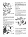
If the discharge area becomes clogged, remove the
flail screen and clean area as follows
e Stop the engine, make certain the chipper-shredder
has come to a complete stop and disconnect spark
plug wire from the spark plug before unclogging the
chute
or washing
with
NOTE: Be certain to reassemble the flail screen with
the curved side clown as shown in figure 19.
13
Chute
Deflector.
Replace or sharpen blades If sharpening, make ogrtain to remove an equal amount from each blade.
Reassemble in reverse order.
Hairpin _
Clips,
Clevis
Pins
Make certain blades are reassembled with the sharp
edge facing the direction shown in figure 19 (sharp
edge is assembled toward the slotted opening in the
impeller assembly).
SHREDDING
--_Hex
Nuts
Washers
Screen
e Disconnect spark plug wire and move it away from
spark plug_
e Lower the hopper assembly
See figure 21.
Chipper
Chute
FIGURE 19.
BLADE
The shredding blade may be removed for sharpening
or replacement as follows.
Block up the housing_
e Remove the six hex lock nuts and lock washers
from the housing weld bolts using a 1/2" wrench
Separate the chipper-shredder into two halves
Hand Knobs
SHARPENING
ORREPLACING
THEBLADES
e Remove the back-up plate.
CHIPPER BLADES
® Disconnect spark plug wire and move it away from
spark plug
NOTE: When reassembling, make certain the opening on the back-up plate is toward the bottom of the
uniL The back-up plate may be reversed to provide a
new cutting edge.
e Remove the flail screen as instructed in previous
section
e Remove the chipper chute by removing three hex
nuts and washers. A 1/2" wrench is required_ See
figure 19.
Allen
Screws
NOTE: When reassembling, the cupped washer goes
on the bottom of the chipper chute with the cupped
side against the chute.
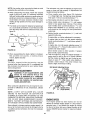
e Rotate the impeller assembly by hand until you
locate one of the chipper blades in the chipper
chute opening. Remove the blade, using a 3/16"
allen wrench on the outside of the blade and 1/2"
wrench on the impeller assembly (inside the housing). See figure 20_
• Remove the other blade in the same manner
Torque
Wrench
FIGURE 21.
e Loosen the two hand knobs and cupped washers
which secure the chute deflector, and raise the
chute deflector
e Insert a 1/2" or 3/4" diameter pipe through the flail
screen into the impeller to keep it from turning, or
remove the flail screen and insert a piece of wood
(2 x 4) into the chute opening.
e Remove
the two outside
screws
on the blade,
using a 3/16" allen wrench and a 1/2" wrench.
e Remove the blade by removing the center bolt, lock
washer and flat washer.
FIGURE 20.
14
NGTE:Usecautionwhenremovingthe blade
to avoid
The carburetor may need re-adjusting if engine lacks
power or does not idle properly If adjustments are
needed, proceed as follows
contacting the weld bolts on the housing_
e When sharpening the blade, follow the original
angle of grind as a guide. It is extremely important
that each cutting edge receives an equal amount of
grinding to prevent an unbalanced blade. An unbalanced blade will cause excessive vibration when
rotating at high speeds and may cause damage to
the unit
e Close needle valve
((_) finger tight only.
Then open 1-1/2 turns
® Start engine and allow
e Close needle valve clockwise (,'-_) until engine
starts to lose speed (lean mixture). Then slowly
open needle valve counterclockwise
(,'_)
until
engine JUST BEGINS to run unevenly. This mixture should be rich enough for best performance
under load
e The blade can be tested for balance by balancing it
on a round shaft screwdriver or nail. Remove metal
from the heavy side until it is balanced evenly. See
figure 22_
O
Nail_\
_
/
(see figure 23) clockwise
Forcing may cause damage.
counterclockwise ( ,'_ )
to warm for five minutes
\
Rotate throttle counterclockwise
against throttle stop.
(,'_)
and hold
If engine idles, no further adjustment is necessary.
If engine idles too fast, turn idle speed adjusting
screw counterclockwise (_)
until slower speed is
obtained.
If engine dies, turn idle speed adjusting screw 1/4
turn clockwise (_)
Place throttle control in FAST
position and restart engine.
FIGURE 22.
e When reassembling the blade, tighten to between
550 and 650 inch pounds, or lacking torque
wrench, tighten securely
O
FLAILS
The flails, located inside the housing,
may be
reversed when they become dull It is suggested that
this procedure be performed by your nearest Sears
Service Department
Idle Speed Adjust _g Screw
Throttle
Idle Mixture
CARBURETOR
ADJUSTMENT
WARNING: IF ANY ADJUSTMENTS
MADE TO THE ENGINE WHILE
Move throttle control to IDLE position. If engine
does not idle, repeat third step
Test the engine by using the chipper-shredder
If
engine tends to stall or die out, it usually indicates
that the mixture is slightly lean and it may be necessary to open ("_) the needle valve slightly to
provide a richer mixture This richer mixture may
cause a slight unevenness in idling.
ARE
THE
ENGINE IS RUNNING (E.G. CARBURETOR)p KEEP CLEAR OF ALL MOVING
PARTS. BE CAREFUL OF HEATED SURFACES AND MUFFLER.
Minor carburetor adjustment may be required to compensate for differences in fuel, temperature, altitude
or load
Needle Valve
(High Speed)
NOTE: A DIRTY AIR CLEANER
WILL CAUSE
ENGINE TO RUN ROUGH.
BE CERTAIN
AIR
CLEANER IS CLEAN AND ATTACHED TO THE
CARBURETOR
BEFORE ADJUSTING CARBURETOR. DO NOT MAKE UNNECESSARY
ADJUSTMENTS FACTORY SETTINGS ARE SATISFACTORY FOR MOST APPLICATIONS AND CONDITIONS
FIGURE 23.
ENGINESPEED
Your engine speed has been factory set Do not
attempt to increase engine speed or it may result in
personal injury If you believe the engine is running
too fast or too slow, take your chipper-shredder to the
nearest SEARS Service Center for repair and adjustment
Never attempt to change maximum engine speed It is
pre-set at the factory and should be changed only by
a qualified service technician who has the necessary
equipment
15
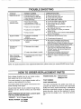
TROUBLE SHOOTING
POSSIBLE CAUSE(S)
CORRECTIVE
Engine fails to start
e
e
e
e
e
e
e
•
Loss of power;
operation erratic
e Spark plug wire loose.
• Unit running on CHOKE
e Blocked fuel line or stale fuel.
PROBLEM
Fuel shut-off valve closed.
Fuel tank empty, or stale fuel.
Spark plug wire disconnected
Faulty spark plug.
e Connect and tighten spark plug wire
• Move choke lever to OFF position
e Clean fuel line; fill tank with clean
fresh gasoline
e Disconnect fuel line at carburetor to drain fuel
tank Refill with fresh fuel
e Adjust carburetor or contact your SEARS
Service Center
• Service air cleaner See Customer Responsibilitie. _
section of this manual.
e Water or dirt in fuel system
e Carburetor out of adjustment
•
Engine overheats
ACTION
Open fuel shut-off valve
Fill tank with clean, fresi_ fuel
Connect wire to spark plug
Clean, adjust gap or replace.
Dirty air cleaner,
•
Carburetor not adjusted
properly
• Engine oil level low.
•
Too much vibration
e Loose parts or damaged
impeller,
• Stop engine immediately and disconnect
spark plug wire Tighten all bolts and nuts.
Make all necessary repair& If vibration continues.
have unit serviced by a SEARS Service Center.
Unit does not
discharge
•
e Stop engine immediately and disconnect
spark plug wire. Clean flail screen and inside
of blower housing See Service/Adjustments
section of this manuel.
e Stop engine immediately and disconnect
spark plug wire. Remove lodged object.
• Fill crankcase with proper oil.
Discharge chute clogged
e Foreign object lodged in impeller
Rate of discharge
slows considerably or
composition of
discharged material
changes
NOTE: For repairs beyond
e Shredding blade and/or chipper
blades dull
the minor adjustments
Contact your SEARS Service Center
•
Sharpen or replace shredding and chipper
blades
listed above, please contact
your nearest
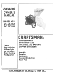
HOW TO ORDER REPLACEMENT
SEARS
Service
PARTS
Each chipper-shredder
has its own model number.
Each engine has its own model number.
*ENGINE MODEL NO. - 190412-6143-01
190432-6117-01
The model number for your chipper-shredder
found on a label attached to the frame
*PART NUMBER
will be
Center.
*PART DESCRIPTION
The model number for the engine will be found on tile
blower housing of the engine
Your Sears merchandise has added value when you
consider that Sears has service units nationwide
All parts listed herein may be ordered through Sears,
Roebuck and Co. Service Centers and most Retail
Stores
staffed with Sears trained technicians professional
technicians specifically trained on Sears prodects,
having the parts, tools and the equipment to insure
that we meet our pledge to you../'we service what we
sell/'
WHEN ORDERING REPAIR PARTS, ALWAYS GIVE
THE FOLLOWING INFORMATION:
*PRODUCT - "8 H.P. Chipper-Shredder"
*MODEL NUMBER - 247.795860
247,795861
16