1
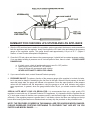
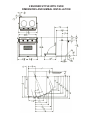
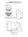
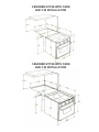
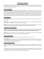
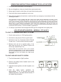
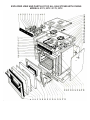
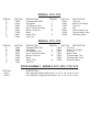
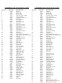
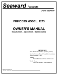
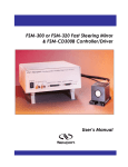
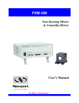
Seaward Products
LPG GAS
STOVES
OWNER’S MANUAL
Installation – Operation - Maintenance
Hillerange Model 2172
Princess Model 3372
Two Burner Gimbaled Gas Range
Three Burner Built-in Gas Range
IMPORTANT:
Read all instructions before operating stove.
Save the Owner’s Manual / Installation instructions
for local inspector’s use.
Installer:
Provide this manual to the vehicle owner.
HILLERANGE / PRINCESS
MODELS: 2172, 2372, 3172, 3372
Serial Number:
Vehicle Owner:
Keep this manual for future reference.
LIMITED TWO YEAR WARRANTY
SEAWARD PRODUCTS warrants the products delivered will be:
A. Free from (1) encumbrances and (2) defects in material and workmanship under the normal use and
service.
B. Will meet applicable specifications and descriptions at time of delivery to BUYER.
The obligation of SEAWARD under this warranty is limited to the repair,
Rework, or replacement, at SEAWARD’S option, any part or component thereof, which examination
discloses to our satisfaction to have been nonconforming or defective. SEAWARD, after establishing
customer’s purchase date and determining problem to be under warranty, will either repair the product at
their factory or authorized service center and allow labor and parts for (2) two years from purchase date.
Transportation charges are the responsibility of the customer. Conditions not covered under warranty are:
(1) Porcelain Enamel
(2) Glass
(3) Routine maintenance that may be required
The foregoing warranty and condition shall apply to any repaired, reworked, or replaced products, part or
component supplied by SEAWARD and shall in no event be liable to BUYER or BUYER’S customers for any
incidental or consequential damages, or loss of use, or other losses, however occasioned.
Implied warranties of merchantability and of the fitness of the product for any purpose are warranted for a
period of two years on parts and labor.
SEAWARD makes no warranties, expressed or implied after that time.
Some states do not allow limitation on how long an implied warranty lasts or for the exclusion or
limitations of incidental or consequential damages, therefore, the above limitations may not apply to you.
This warranty is extended to the original purchaser only, unless purchased for purpose of resale. This
warranty gives you specific legal rights, and you may also have other rights which vary from state to state.
Seaward Products
REPAIR PARTS
Repair parts listed herein may be ordered through Seaward Products. Seaward Distributors and Dealers,
or Dealer’s Authorized Service Centers. All parts will be shipped at prevailing prices.
When ordering repair parts, please give the following information:
(1) The part number
(2) The part description
(3) The model number of the stove
(4) The serial number of the stove
The model number and serial number of the water heater will be found on the rating plate located on the
front panel. For the Authorized Service Center nearest you, please contact Seward Products.
Seaward Products
3721 Capitol Avenue
Whittier, CA 90601-1732
Tel. (562) 699-7997 Fax. (562) 699-0908
www.seawardproducts.com
10-18-05 #72375
LPG FUEL TANK INSTALLATION
REFERENCE:
STANDARD #A-1
AMERICAN BOAT & YACHT COUNCIL
3069 SOLOMON’S ISLAND ROAD
EDGEWATER, MD 21037
LPG TANK WITH REGULATION SYSTEM
1. Locate the tank and regulator on deck, cabin top or in a vapor tight compartment, insulated from the
hull interior and protected from climatic extremes by a housing vented to the open air. The vent
should be at the bottom of the compartment so that if the LPG should leak from the system, it will
drain overboard.
.
NOTE:
LPG is heavier than air and if allowed to settle or accumulate, and if ignited, it WILL
CAUSE AN EXPLOSION!!
2. The LPG tank should be securely bolted down by the tank feet and in the position in which the tank
was designed. LPG is a two-phase (liquid/vapor) fuel and only vapor withdrawal from the tank is
safe. Liquid withdrawal from the tank could be dangerous.
3. IMPORTANT: The LPG tank valve outlet fitting and regulator system nut, by law, must have lefthand threads. The nut is so marked with a slot.
4. The LPG tank valve outlet fitting does not require pipe dope or Teflon tape and should be attached
to the regulation system nut dry and clean to keep foreign materials out of the system. When
assembling the regulation system, use a high quality sealant only on all male pipe threads.
5. The regulator must have a 0 to 300 psi pressure gauge located on the tank pressure side of the
regulator.
6. If the LPG tank is to be located on deck or exposed to water spray, point the regulator system so
that water cannot run into the regulator vent port located just above the LPG outlet connection, or
into the body of the pressure gauge.
7. Use a 7/8” open end wrench to tighten the regulation system nut to the LPG tank valve connection.
Tighten the nut as you would on welding tanks or CO2 cylinders, using approximately 50 foot
pounds torque.
8. Affix the caution label supplied with the stove in the immediate vicinity of the tank where the label
will be plainly visible. (Refer to ABYC Standard #A-1)
9. The LPG supply line should be U.L. listed hose with machine-crimped fittings. A single continuous
hose without couplings or tees is strongly recommended. Keep the number of fittings to an absolute
minimum. Every connection is a potential leak!
10. Run the hose from the LPG regulation system to the appliance with 6 – inch minimum radius turns,
so the hose does not kink, cutting off the fuel supply to the appliance. Note: Fuel pressure is less
than ½ psi.
11. Keep hose away from heat or abrasion. Use plastic ties or clamps to secure the hose to the boat
structure or bulkheads
.
SUMMARY FOR CHECKING LPG SYSTEM AND LPG APPLIANCE
1. After the LPG tank has been installed, the regulation system connected, the hose run and connected to
both the appliance and the regulator, slowly crack open the LPG tank valve and observe the pressure
gauge on the regulation system. The gauge should read approximately 110 psi at 70° F. (Higher if
warmer, or lower if cooler atmospheric temperature.)
2. Close the LPG tank valve and observe the pressure gauge. It should hold a constant pressure reading.
If you can detect a falling in pressure over a 3 minute period of time, there is a leak. LEAKS CAN BE
DANGEROUS!!
.
a. If a leak occurs, check all appliance burners to see if in “Off” position.
b. Make sure the oven control is in “Off” position.
c. Check all fittings with a soap and water solution.
NEVER USE FLAME TO CHECK FOR LEAKS.
3. If you cannot find the leak, contact Seaward Products promptly.
4. PRESSURE GAUGE: The primary function of the pressure gauge at the regulator is to check for leaks,
but it may also be helpful in determining the fuel level in the tank. When the liquid propane in the tank
nears the empty state, the gauge will indicate a low pressure. Since the vapor pressure of the propane
varies with the ambient and the temperature, using the gauge as a fuel level indicator may require
some experience, In general, when the gauge shows below 40 psi, you should consider refilling the
tank.
SPECIAL NOTE ABOUT YOUR LPG REGULATOR: It is recommended that only a high quality LPG
regulator be used with any of Seaward Products LPG appliances. It is imperative that the regulator be set
at 11 inch water column so that the oven operates correctly, and the flame height on the top burners cooks
efficiently. If the regulator pressure is greater than 11 inch water column, the flame can impinge on the top
burner bowl causing discoloration on stainless bowls and may chip the porcelain on the porcelain bowls.
NOTE: THE FEATURES COVERED IN THIS MANUAL ARE FOR VARIOUS MODEL RANGES.
PLEASE DISREGARD PORTIONS PERTAINING TO FEATURES THAT ARE NOT ON YOU
PARTICULAR MODEL RANGE……..
GIMBALD MODELS – 2 & 3 BURNERS
1. It is important that the following minimum clearances from combustible materials be adhered to when
installing your gimbaled range.
.
2 BURNER MODEL:
• Side – 7” minimum as measured from the center line of the closest burner head.
• Rear - 9” minimum as measured from the center line of the closest burner head.
• Top – 24” minimum to overhead cabinets, shelves or any other combustible material.
3 BURNER MODEL:
• Side – 5.1/2” minimum as measured from the center line of the closest burner head.
• Rear - 7” minimum as measured from the center line of the closest burner head.
• Top – 24” minimum to overhead cabinets, shelves or any other combustible material.
2. Make a cardboard template the same size as the side view of the range. Punch a hole at the gimbal
location the size of the gimbal, and swing the appliance template in the appliance cut-out location in the
boat on your finger. By allowing a swing approximately 15° to 20° before interference with the hull or
boat structure, the gimbal point can be located. Mark the point. Make certain that after the gimbal point
is determined that the installation matches or exceeds the minimum clearance in paragraph #1. It is
important that the oven vent be completely clear so that burned gases can discharge to the open air. If
this vent is blocked, poisonous gas could be produced.
.
3. Locate the companion pieces to the gimbals and install the appliance.
4. For safety, Seaward Products gimbaled appliances are designed with a sliding bolt type lock. The
sliding bolt should lock into an adjacent cabinet or bulkhead to prevent the appliance from swinging in
rough weather.
CAUTION:
The appliance center of gravity will also shift from the gimbal location when pots are
not balanced on the appliance or when the appliance door is open.
5. Connect the LPG fuel supply hose fitting to the brass fitting on the appliance manifold and on the
regulation system. Wrench tighten the fitting to the connection on the appliance. DO NOT use pipe
dope or Teflon tape.
6. Check all gas connections for possible leaks. Turn the valves on your range to their “OFF” position.
Open valve on gas supply tank. Using a strong soap and water solution,( ½ liquid soap and ½ water),
check each gas connection one at a time by brushing the soap and water solution over the connection.
Presence of bubbles will indicate a leak. Tighten fitting and recheck for leaks. DO NOT USE OPEN
FLAME FOR CHECKING GAS LEAKS.
7. Place burner grates in place with the clips provided. An instruction sheet is provided for the grate clips.
These grate clips will hold the grate in place while under way.
8. Light the burners for testing.
9. The appliance is now ready for use. Sometimes the burners will not ignite immediately and seem to
“blow” slightly when they do ignite. This is usually due to the presence of air in the gas lines, which will
clear itself within seconds.
2 BURNER STOVE WITH OVEN
DIMENSIONS AND GIMBAL INSTALLATION
3 BURNER STOVE WITH OVEN
DIMENSIONS AND GIMBAL INSTALLATION
2 BURNER STOVE WITH OVEN
BUILT-IN INSTALLATION
3 BURNER STOVE WITH OVEN
BUILT-IN INSTALLATION
CARE AND CLEANING
Regular cleaning with a soft cloth and a warm detergent solution is generally enough to keep your oven
clean and beautiful. This is done when the range is cool. Use a dry cloth or paper towel to clean splatters
and spills when surfaces are warm.
PORCELAIN ENAMEL
Porcelain enamel is glass fused on steel at very high temperatures. It is not extremely delicate, but must be
treated as glass. Sharp blows, radical changes in temperature, etc., will cause the enamel to chip or crack.
Some foods contain acid which will dull the finish of enamel. Vinegar, lemon juice, tomatoes, and milk are a
few. To avoid this happening, simply wipe surface clean immediately when any food is spilled on the
enamel. Remember, the surface is glass and must be given consideration in cleaning. Steel wool pads and
coarse gritty cleansing powders or chemical grease remover will do a good job and yet not harm the finish.
GLASS SURFACE
The extra large glass window is built to stay FOG – FREE. To keep it clean, just wipe with a moist, soft
cloth and dry.
CAUTION: Do not clean the window with water while the oven is warm. The glass is strong, but radical
heat changes or a sharp blow will crack it. Use care in cleaning.
NOTICE: When the unit is in operation, the outside surfaces will become hot and care must be taken to
avoid contact with panel surfaces. Handles and knobs will remain comfortable to the touch.
CHROME AND STAINLESS STEEL
The best way to clean metal surfaces on your range is to wipe them with a damp cloth, then dry thoroughly.
Stubborn spots caused by spillage and discoloration from heat may be removed by the use of lemon juice,
vinegar, or chrome polish. Care must be used to keep these away from porcelain enamel surfaces.
NEVER use coarse cleansers, steel wool scouring pads or metal brushes to clean chrome. These will
make deep scratches on the chrome. The scratches cannot be removed.
USE OF ALUMINUM FOIL
IN THE OVEN – Do not use aluminum foil in your oven to cover racks or oven bottom.
IN THE BROILER – Aluminum foil may be used to line the bottom part of the two-piece broiler pan, but if
foil is placed over the slotted broiler tray, care must be taken to slit the foil at each slot so that drippings
and excess grease can drain in the pan below.
INSIDE OVEN AND BROILER
Racks and broiler pan may be removed and cleaned in your sink with other cooking utensils. The inside
surfaces of the oven is porcelain enamel and should be cleaned by the method given in the enamel
section.
The Capillary Tube in the oven is not removable. This senses oven temperature and is perhaps the most
fragile part of your range. Be sure to gently wipe off this tube after using an oven spray cleaner, the cleaner
can “build up” on the tube and may cause a false temperature reading.
LPG STOVE - OPERATING INSTRUCTIONS
1. It is recommended that every time the LPG tank valve is opened for use, the operator close the
valve and watch that the gauge needle remains constant.
2. If leaks occur, correct. If leaks cannot be corrected, do not operate appliance.
3. Always test light a top burner after opening the tank valve to dispose of air in the supply line. This
could be caused by someone’s opening the system to fill a LPG tank or by opening a burner valve.
Following this step will make lighting the oven safety heater pilot much easier.
4. In an emergency, close the LPG tank valve immediately.
5. The pressure gauge on the LPG regulation system is only a leak detector. The gauge does not
indicate how much LPG fuel is in the tank.
6. Before removing an empty or near empty LPG tank for refilling:
• IMPORTANT – Always close the LPG tank valve.
• With the tank valve closed, remove the left-hand threaded nut connecting the regulation system
to the tank valve. Carefully stow the regulation system until a full tank is mounted and secure.
• Reconnect the regulation system. Left-hand thread. Use no Teflon tape or pipe dope.
7. When transporting a LPG tank, always be aware that the tank valve has a built-in relief valve that
could open and allow LPG fuel to escape in automobile, storage area, or anywhere!
8. When the appliance is not being used, always close the main gas valve on the LPG tank supplying
fuel to the appliance.
LPG OVEN - OPERATING INSTRUCTIONS
1. Light the right front burner to bleed air from the system for at least 1 minute. Turn the temperature
control knob from the “Off” position to the “Pilot On” position. After this has been done, light the pilot
in the oven (constant pilot).
2. After the oven pilot is lit, turn the oven temperature control knob to the desired temperature
(example 350°).
3. You will notice the constant pilot grow in size. It is now being used as a heater pilot. The heater pilot
will heat the sensing bulb from the mercury control valve. Once this sensing bulb reaches a
sufficient temperature, it will open the mercury control valve permitting it to release gas to the main
burner and the main burner will ignite. This will happen in 30 to 60 seconds.
4. When the oven has reached the desired temperature, the thermostat will stop the supply of gas to
the heater pilot, and once again it will become the constant pilot, thus causing the sensing bulb from
the mercury control valve to cool. The mercury valve will close and stop the gas supply to the main
burner.
5. When the oven requires more heat, the same cycle will again repeat itself. The only time the oven
will operate differently would be when the thermostat is in the “Broil” position. The main burner
flame would then increase in size and not shut off until the thermostat was turned down or to the
“Off” position.
6. Important: Then oven thermostat on this LPG range is designed to enable you to turn off the oven
constant pilot by simply turning the thermostat dial to the “Off” position. When the dial is in this
position, you cannot light the constant pilot. When the dial is in the “Pilot On” position, the pilot is
on.
OPERATING INSTRUCTIONS SUMMARY FOR A LPG SYSTEM
1. Close tank valve immediately in any emergency.
2. Be sure all appliance valves are closed before opening tank valve.
3. Always apply lit match or other flame to burner before opening valve.
4. Close tank valve whenever appliance is not in use.
5. Test system for leakage at least twice a month and after any emergency in accordance with the
following procedure:
WITH APPLIANCE VALVES CLOSED AND WITH TANK VALVE OPEN, NOTE PRESSURE ON GAUGE. CLOSE
CYLINDER VALVE. IF THE PRESSURE DROPS, AS INDICATED ON THE GAUGE, THIS TELLS YOU THERE IS A
LEAK IN THE SYSTEM. LOCATE LEAKAGE BY APPLICATION OF LIQUID DETERGENT OR SOAP AND WATER
SOLUTION TO ALL CONNECTIONS. AFTER LEAK HAS BEEN REPAIRED, RECHECK SYSTEM BY REPEATING THIS
ABOVE TEST. IF LEAK CANNOT BE REPAIRED, CLOSE TANK VALVE IMMEDIATELY AND DO NOT USE THIS
SYSTEM. REMEMBER LPG IS HEAVIER THAN AIR AND IF ALLOWED TO REACH BILGES, MACHINERY SPACE OR
OTHER ENCLOSED SPACES, IT CAN BE EXTREMELY DANGEROUS.
6. It is always a good idea to have an approved ABC type fire extinguisher in the galley area.
LPG STOVE WITH IGNITER – MODELS: 3172 & 3372
TO LIGHT TOP BURNERS WITH SAFETY SYSTEM
1. Push in knobs and turn to “IGN” (Ignite) position.
2. Hold knob in and press the “Burner Ignite” button.
3. Hold knob in for 5 to 10 seconds until the Thermal
Couple is hot. This will activate the safety magnet.
4. Release knob and set to desired setting. If the
flame does not stay on, the Thermal Couple is not
hot enough. (Repeat Steps 1-4).
SPARK FROM THE ELECTRODE HAS TO CUT ACROSS
THE GAS TO IGNITE READILY. IF THE SPARK IS JUMPING
BELOW THE BURNER PORTS ADJUST THE POINT OF THE
ELECTRODE SO THAT THE SPARKS WILL JUMP ABOVE
THE PORTS.
TO LIGHT OVEN WITH SAFETY SYSTEM
1. Turn the thermostat to “light” position.
2. Push-in the safety button located next to the
thermostat knob.
3. Light the burner ignition unit with a lighter or a
match.
4. Hold the safety button pushed-in for
approximately 10 to 15 seconds and slowly
release the button. The flame should remain. If
not repeat the procedure.
.125 ± .015
.185 ±
.010
.200 ± .015
EXPLODED VIEW AND PARTS LIST OF ALL GAS STOVES WITH OVENS
MODELS: 2172, 2372 / 3172, 3372
MODELS: 2172, 2372
ITEM NO.
A
B
C
D
E
F
G
H
PART NO.
73389
72419
73976
70507
72540
72199
72547
73392
DESCRIPTION
Faceplate 2BR 100%
Gas Lighter
100% Burner Valve
Hood, Top Burner Valve
Burner, Front Left
Bezel
Safety, Pilot
Fuel, Line
ITEM NO.
I
J
K
L
M
N
PART NO.
73972
72541
72513
N/A
72622
72555
72552
DESCRIPTION
Fuel Line
Burner, Front Right
Fuel Line
N/A
Thermocouple, Top
Thermocouple, Oven
Electrode, Igniter
MODELS: 3172, 3372
ITEM NO.
A
B
C
D
E
F
G
H
PART NO.
73390
73956
73976
70507
72540
72199
72547
73392
DESCRIPTION
Faceplate 2BR 100%
Gas Lighter
100% Burner Valve
Hood, Top Burner Valve
Burner, Front Left
Bezel
Safety, Pilot
Fuel Line
ITEM NO.
PART NO.
DESCRIPTION
I
73972
Fuel Line
J
72541
Burner, Front Right
K
72513
Fuel Line
L
72542
Burner, Rear
M
72622
Thermocouple, Top
72555
Thermocouple, Oven
N
72552
Electrode, Igniter
DOOR ASSEMBLY - MODELS: 2172, 2372, 3172, 3372
PART NO.
80011
80010
DESCRIPTION
Door Assembly, Black Glass (Items: 14, 15, 16, 18, 19, 20, 21, 22)
Door Assembly, Stainless Steel (Items: 16, 17, 18, 19, 20, 21, 22)
2 BURNER GAS STOVE WITH OVEN
ITEM NO.
1
2
3
4
5
6
7
8
9
10
11
12
13
14
15
16
17
18
19
20
21
22
23
24
25
26
27
28
29
30
31
32
33
34
35
36
37
38
39
40
41
42
43
44
45
46
47
48
49
50
51
52
53
54
55
PART NO.
72536
72537
72538
72532
73391
70506
70507
74498
72219
73387
72294
73577
80047
80052
80303
73865
74099
72244
72248
72225
72715A
70101
72196
72226
80264
80265
72454
72215
72553
72249
72557
72558
72267
72268
72290
72326
70198
73432
73433
80004
72295
72208
72227
72222
72715B
80048
72347
72715C
72280
80051
72217
72510
80136
72596
72300
72277
72278
72245
72271
72306
72543
70114
70113
3 BURNER GAS STOVE WITH OVEN
DESCRIPTION
ITEM NO.
Manifold
Burner, Left
Burner, Right
Mercury Valve
Fuel Line, Therm. To Merc.
Valve, Top Burner
Hood, Burner Valve, LPG
Thermostat
Tray, Component
Face Plate
Trim, Control Panel
Face Plate
Panel, Side, LH 2172
Panel, Side, LH 2372
Frame, Door
Glass, Oven Door, BLK
Handle, Door
Door Panel, SS
Door Panel, Porcelain
Door Liner
Insulation, Door
Glass, Window, Door For SS
Glass, Window, Door For BLK Glass
Door Liner
Hinge Assy, Door LH
Hinge Assy, Door RH
Arm, Spring
Spring, Door
Pilot Assy
Flame Spreader
Burner, Oven
Hood, Oven
Trim, Lower 2372
Trim, Lower 2172
Oven Bottom
Rack, Oven
Broiler Pan w/ Insert
Gasket, Oven Top
Gasket, Oven Side
Oven Can
Shield, Radiation
Bottom, Ext
Retainer, Filler 2172
Filler Angle 2372
Insulation, Oven Can
Panel, Side RH 2172
Pin, Gimbal
Insulation, Back
Panel, Back
Panel, Side LH 2172
Burner Box
Fuel Line, Pilot
2 Burner Fuel Line
Shoulder Bolt
Grommet, ½”
Upper Back 2372
Upper Back 2172
Main Top, SS
Main Top, Porcelain
Grommet, 1 1/8”
Fitting, LPG
Grate
Clip, Grate
1
2
3
4
5
6
7
8
9
10
11
12
13
14
15
16
17
18
19
20
21
22
23
24
25
26
27
28
29
30
31
32
33
34
35
36
37
38
39
40
41
42
43
44
45
46
47
48
49
50
52
53
54
55
56
57
PART NO.
72535
72537
72538
72532
73391
70506
70507
74498
72219
73388
72294
73577
80045
80040
80303
73865
74099
72244
72248
72225
72715A
70101
72196
72226
80264
80265
72454
72215
72553
72554
72249
72557
72558
72267
72268
72289
72325
73044
73045
73432
73433
80004
72295
72208
72227
72222
72715B
80044
72347
72715C
72280
80037
72223
72510
80135
72596
72300
72277
72278
72306
72543
70114
70113
72250
72273
72539
DESCRIPTION
Manifold
Burner, Left
Burner, Right
Mercury Valve
Fuel Line, Therm. To Merc.
Valve, Top Burner
Hood, Burner Valve, LPG
Thermostat
Tray, Component
Face Plate
Trim, Control Panel
Face Plate
Panel, Side, LH 3172
Panel, Side, LH 3372
Frame, Door
Glass, Oven Door, BLK
Handle, Door
Door Panel, SS
Door Panel, Porcelain
Door Liner
Insulation, Door
Glass, Window, Door For SS
Glass, Window, Door For BLK Glass
Door Liner
Hinge Assy, Door LH
Hinge Assy, Door RH
Arm, Spring
Spring, Door
Pilot Assy 3172
Pilot Assy 3372
Flame Spreader
Burner, Oven
Hood, Oven
Trim, Lower 3372
Trim, Lower 3172
Oven Bottom
Rack, Oven
Broiler Pan
Gasket, Oven Top
Gasket, Oven Side
Oven Can
Shield, Radiation
Bottom, Ext
Retainer, Filler 3172
Filler Angle 3372
Insulation, Oven Can
Panel, Side RH 3172
Pin, Gimbal
Insulation, Back
Panel, Back
Panel, Side LH 3332
Burner Box
Fuel Line, Pilot
3 Burner Fuel Line
Shoulder Bolt
Grommet, ½”
Upper Back 2372
Upper Back 2172
Grommet, 1 1/8”
Fitting, LPG
Grate
Clip, Grate
Main Top, SS, 3172, 3372
Main Top Porcelain, 3172, 3372
Burner, Rear, 3172, 3372