1
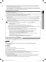
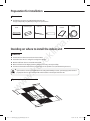
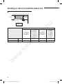
a. hu lim ek ev .k w w w "EEE Yönetmeliğine Uygundur" "This EEE is compliant with RoHS" NS***4PXEA_IM_E_32787A(8).indd 24 2012-10-18 오후 2:11:50 Cassette Type Series a. hu ACFB4DEH ACFB4PEH ACFB4FEH NS4PXEA NS4DXEA NS4ZXEA lim Air Conditioner w w w .k ev ek installation manual imagine the possibilities Thank you for purchasing this Samsung product. To receive more complete service, please register your product at www.samsung.com/register E S F I P D G R DB98-32787A(8) NS***4PXEA_IM_E_32787A(8).indd 25 2012-10-18 오후 2:11:50 Contents a. hu Preparation for installation . .............................................................................................................................................................................................. 3 Deciding on where to install the indoor unit . .......................................................................................................................................................... 4 Indoor unit installation . ...................................................................................................................................................................................................... 8 Purging the unit ..................................................................................................................................................................................................................... 9 Connecting the refrigerant pipe . ................................................................................................................................................................................... 9 Cutting/Flaring the pipes ................................................................................................................................................................................................ 10 Performing leak test & insulation ................................................................................................................................................................................ 11 Drainpipe and drain hose installation . ..................................................................................................................................................................... 12 Installing DPM ...................................................................................................................................................................................................................... 14 Connecting the connection cord ................................................................................................................................................................................ 15 Setting an indoor unit address and installation option...................................................................................................................................... 16 Troubleshooting . ................................................................................................................................................................................................................ 23 Safety precautions Carefully follow the precautions listed below because they are essential to guarantee the safety of the equipment. lim WARNING • Always disconnect the air conditioner from the power supply before servicing it or accessing its internal components. • Verify that installation and testing operations are performed by qualified personnel. • Verify that the air conditioner is not installed in an easily accessible area. General information Carefully read the content of this manual before installing the air conditioner and store the manual in a safe place in order to be able to use it as reference after installation. For maximum safety, installers should always carefully read the following warnings. Store the operation and installation manual in a safe location and remember to hand it over to the new owner if the air conditioner is sold or transferred. This manual explains how to install an indoor unit with a split system with two SAMSUNG units. The use of other types of units with different control systems may damage the units and invalidate the warranty. The manufacturer shall not be responsible for damages arising from the use of non compliant units. This product has been determined to be in compliance with the Low Voltage Directive (2006/95/EC), and the Electromagnetic Compatibility Directive (2004/108/EC) of the European Union. The manufacturer shall not be responsible for damage originating from unauthorized changes or the improper connection of electric and requirements set forth in the “Operating limits” table, included in the manual, shall immediately invalidate the warranty. The air conditioner should be used only for the applications for which it has been designed: the indoor unit is not suitable to be installed in areas used for laundry. Do not use the units if damaged. If problems occur, switch the unit off and disconnect it from the power supply. In order to prevent electric shocks, fires or injuries, always stop the unit, disable the protection switch and contact SAMSUNG’s technical support if the unit produces smoke, if the power cable is hot or damaged or if the unit is very noisy. Always remember to inspect the unit, electric connections, refrigerant tubes and protections regularly. These operations should be performed by qualified personnel only. The unit contains moving parts, which should always be kept out of the reach of children. Do not attempt to repair, move, alter or reinstall the unit. If performed by unauthorized personnel, these operations may cause electric shocks or fires. Do not place containers with liquids or other objects on the unit. All the materials used for the manufacture and packaging of the air conditioner are recyclable. The packing material and exhaust batteries of the remote controller(optional) must be disposed of in accordance with current laws. The air conditioner contains a refrigerant that has to be disposed of as special waste. At the end of its life cycle, the air conditioner must be disposed of in authorized centers or returned to the retailer so that it can be disposed of correctly and safely. w w w .k ev ek Installing the unit IMPORTANT: When installing the unit, always remember to connect first the refrigerant tubes, then the electrical lines. Always disassemble the electric lines before the refrigerant tubes. Upon receipt, inspect the product to verify that it has not been damaged during transport. If the product appears damaged, DO NOT INSTALL it and immediately report the damage to the carrier or retailer (if the installer or the authorized technician has collected the material from the retailer.) After completing the installation, always carry out a functional test and provide the instructions on how to operate the air conditioner to the user. Do not use the air conditioner in environments with hazardous substances or close to equipment that release free flames to avoid the occurrence of fires, explosions or injuries. 2 NS***4PXEA_IM_E_32787A(8).indd 2 2012-10-18 오후 2:10:44 Our units should be installed in compliance with the spaces shown in the installation manual, to ensure accessibility from both sides and allow repairs or maintenance operations to be carried out. The unit’s components should be accessible and easy to disassemble without endangering people and objects. For this reason, when provisions of the installation manual are not complied with, the cost required to access and repair the units (in SAFETY CONDITIONS, as set out in prevailing regulations) with harnesses, ladders, scaffolding or any other elevation system will NOT be considered part of the warranty and will be charged to the end customer. Power supply line, fuse or circuit breaker a. hu ENGLISH Always make sure that the power supply is compliant with current safety standards. Always install the air conditioner in compliance with current local safety standards. Always verify that a suitable grounding connection is available. Verify that the voltage and frequency of the power supply comply with the specifications and that the installed power is sufficient to ensure the operation of any other domestic appliance connected to the same electric lines. Always verify that the cut-off and protection switches are suitably dimensioned. Verify that the air conditioner is connected to the power supply in accordance with the instructions provided in the wiring diagram included in the manual. Always verify that electric connections (cable entry, section of leads, protections…) are compliant with the electric specifications and with the instructions provided in the wiring scheme. Always verify that all connections comply with the standards applicable to the installation of air conditioners. Devices disconnected from the power supply should be completely disconnected in the condition of overvoltage category. Make sure that you earth the cables. .k ev ek lim - Do not connect the earth wire to the gas pipe, water pipe, lighting rod or telephone wire. If earthing is not complete, electric shock or fire may occur. Install the circuit breaker. - If the circuit breaker is not installed, electric shock or fire may occur. Make sure that the condensed water dripping from the drain hose runs out properly and safely. Install the power cable and communication cable of the indoor and outdoor unit at least 1m away from the electric appliance. Install the indoor unit away from lighting apparatus using the ballast. - If you use the wireless remote control, reception error may occur due to the ballast of the lighting apparatus. Do not install the air conditioner in following places. - Place where there is mineral oil or arsenic acid. Resin parts flame and the accessories may drop or water may leak. The capacity of the heat exchanger may reduce or the air conditioner may be out of order. - The place where corrosive gas such as sulfurous acid gas generates from the vent pipe or air outlet. The copper pipe or connection pipe may corrode and refrigerant may leak. - The place where there is a machine that generates electromagnetic waves. The air conditioner may not operate normally due to control system. - The place where there is a danger of existing combustible gas, carbon fiber or flammable dust. The place where thinner or gasoline is handled. Gas may leak and it may cause fire. w Preparation for installation When deciding on the location of the air conditioner with the owner, the following restrictions must be taken into account. w General w Do NOT install the air conditioner in a location where it will come into contact with the following elements : Combustible gases Saline air Machine oil Sulphide gas Special environmental conditions If you must install the unit in such conditions, first consult your dealer. Avoid installing the air conditioner : In areas where it is exposed to direct sunlight. Close to heat sources. In damp areas or locations where it could come into contact with water. (for example rooms used for laundry) In areas where curtains and furniture could affect the supply and discharge of air. Without leaving the required minimum space around the unit. (as shown in the drawing) In scarcely ventilated areas. On surfaces that are unable to support the weight of the unit without deforming, breaking or causing vibrations during the use of the air conditioner. In a position that does not enable the condensate drainage pipe to be correctly installed. (at the end of the installation. It is always essential to check the efficiency of the drainage system) NS***4PXEA_IM_E_32787A(8).indd 3 3 2012-10-18 오후 2:10:44 Preparation for installation Accessories The following accessories are supplied with the indoor unit. The type and quantity may differ depending on the specifications. Insulation pipe Cable-tie Drain hose Installation manual Clamp lim a. hu Insulation cover band Deciding on where to install the indoor unit ek Indoor unit ev There must be no obstacles near the air inlet and outlet. Install the indoor unit on a ceiling that can support its weight. Maintain sufficient clearance around the indoor unit. Make sure that the water dripping from the drain hose runs away correctly and safely. The indoor unit must be installed in this way, that they are out of public access. (Not touchable by the users) w .k • If you install the cassette type indoor unit on the ceiling with humidity over 80%, you must apply extra 10mm of polyethylene foam or other insulation with similar material on the body of the indoor unit. w w Space requirements for indoor unit 4 NS***4PXEA_IM_E_32787A(8).indd 4 2012-10-18 오후 2:10:44 When installing a cassette type indoor unit on the ceiling and its installation condition is temperature over 27°C and humidity over 80%, install a 10mm thickness of polyethylene insulation or similar type of insulation on the indoor unit body. D E B A ENGLISH Insulation installation guide Cut the part where pipes are pulled out or some curved part for insulating work. When insulating a connecting duct, the outlet and inlet part (front, back) should be insulated together. C Thickness: more than 10mm 4way Cassette <M> (840x246x840) 4way Cassette <S> (840x204x840) B 910X235 940X235 C 910X193 910X151 D E a. hu Cassette type A 940X193 ek 4way Cassette <L> (840x288x840) 090FB4P 100FB4P 100FB4F 0904PX 1254X 1004PX 1004ZX 071FB4P 090FB4D 100FB4D 0714PX 0904DX 1004DX 052FB4D 071FB4D 0714DX 610X235 650X235 870X870 610X193 650X193 870X870 610X151 650X151 870X870 lim Indoor unit 940X151 ev Insulate the end of the pipe and some curved area by using separate insulator. w .k •The units must be installed according to distances declared, in order to permit accessibility from each side, either to guarantee correct operation of maintenance or repairing products. The unit’s parts must be reachable and removable completely under safety condition (for people or things). w w • Do not hold the discharge while carrying the indoor unit to avoid the possibility of breakage. You must hold the hanger plate on the corner and carry the indoor unit. 5 NS***4PXEA_IM_E_32787A(8).indd 5 2012-10-18 오후 2:10:45 Deciding on where to install the indoor unit Required space for an indoor unit installation 1500mm or more 2500mm or more 17mm 20mm a. hu ‘C’mm Obstruction MODEL Net dimension mm 251 293 335 335 840×246×840 840×288×840 840×288×840 ek mm 840×204×840 w w w .k ev C 090FB4P 0904PX 1254DX 100FB4P 100FB4F 1004PX 1004ZX 1254PX 1404PX 1404DX lim 052FB4D 071FB4D 0714DX 071FB4P 090FB4D 100FB4D 0714PX 0904DX 1004DX 6 NS***4PXEA_IM_E_32787A(8).indd 6 2012-10-18 오후 2:10:45 Drawing of the indoor unit ENGLISH 890~910 (Celling opening) 950 Unit : mm 55 a. hu ek lim 735 (Suspension position) 950 890~910 (Celling opening) 735 (Suspension position) 840 370 346 185 840 55 45 330 w 204 253 840 X 204 X 840 15.0 1/4" 1/2" 216 300 MODEL w w A mm B mm Net dimension mm Net weight kg Liquid pipe connection Gas pipe connection Drain Hose connection mm 240 270 Sub duct connection 071FB4D 052FB4D 0714DX 164 86 96 120 ev A .k B 55 071FB4P 0714PX 090FB4D 100FB4D 0904DX 1004DX 246 295 840 X 246 X 840 16.0 100FB4P 100FB4F 090FB4P 1004PX 0904PX 1004ZX 1254DX 1254PX 1404DX 1404PX 288 337 840 X 288 X 840 18.0 20.0 3/8" 5/8" OD : Φ32.0, ID : Φ26.5 7 NS***4PXEA_IM_E_32787A(8).indd 7 2012-10-18 오후 2:11:38 Indoor unit installation When deciding on the location of the air conditioner with the owner, the following restrictions must be taken into account. 1. Determine the position of the pipe and drain hose hole as seen in the picture and drill the hole with an inner diameter of 65mm so that it slants slightly downwards. 2. Insert bolt anchors, use existing ceiling supports or construct a suitable support as shown in figure. 3. Install the suspension bolts depending on the ceiling type. a. hu •Since the diagram is made of paper, it may shrink or stretch slightly due to temperature or humidity. For this reason, before drilling the holes maintain the correct dimensions between the markings. Insert Hole in anchor Hole in plug Suspension bolt(M8)-field supply lim •Ensure that the ceiling is strong enough to support the weight of the indoor unit. Before hanging the unit, test the strength of each attached suspension bolt. •If the length of suspension bolt is more than 1.5m, it is required to prevent vibration. Concrete 4. Screw eight nuts to the suspension bolts making space for hanging the indoor unit. Ceiling support ev ek •You must install all the suspension rods. •It is important to leave sufficient space in the false ceiling to allow access for maintenance or repairs to the drainage pipe connection, the refrigerant pipe connection, or to remove the unit if necessary. 5. Hang the indoor unit to the suspension bolts between two nuts. w .k •Piping must be laid and connected inside the ceiling when suspending the unit. If the ceiling is already constructed, lay the piping into position for connection to the unit before placing the unit inside the ceiling. w 6. Screw the nuts to suspend the unit. Cut a pad stopper and place it on the bracket at this time. 7. Adjust the unit to the appropriate position considering the installation area for the front panel. 1) Place the pattern sheet on the indoor unit. w Pad stopper Bracket 2) Adjust a space between the ceiling and the indoor unit by using the gauge of dimensions. 3) Fix the indoor unit securely after adjusting level of the unit by using a leveler. 4) Remove the pattern sheet, connect the other cables and install the front panel. Indoor unit 17mm 20mm Ceiling Gauge of Dimensions 8 NS***4PXEA_IM_E_32787A(8).indd 8 2012-10-18 오후 2:11:39 Purging the unit From factory the unit is supplied and set with a pre-charge of nitrogen gas. (insert gas) Therefore, all insert gas must be purged before connecting the assembly piping. Unscrew the pinch pipe at the end of each refrigerant pipe. •To prevent dirt or foreign objects from getting into the pipes during installation, do NOT remove the pinch pipe completely until you are ready to connect the piping. Gas refrigerant port a. hu Connecting the refrigerant pipe ENGLISH Liquid refrigerant port RESULT : All inert gas escapes from the indoor unit. lim There are two refrigerant pipes of different diameters : A smaller one for the liquid refrigerant A larger one for the gas refrigerant The inside of copper pipe must be clean & has no dust 1. Remove the pinch pipe on the pipes and connect the assembly pipes to each pipe, tightening the nuts, first manually and then with a torque wrench, a spanner applying the following torque. Refrigerant oil Spanner ek Torque wrench Flare nut ev Union Outer Diameter (D) Torque (N•m) ø6.35 mm ø9.52 mm ø12.70 mm ø15.88 mm ø19.05 mm 18 42 55 65 100 .k •If the pipes must be shortened refer to page 9. w 2. Must use insulator which is thick enough to cover the refrigerant tube to protect the condensate water on the outside of pipe falling onto the floor and the efficiency of the unit will be better. 3. Cut off any excess foam insulation. w 4. Be sure that there must be no crack or wave on the bended area. w 5. It would be necessary to double the insulation thickness(10mm or more) to prevent condensation even on the insulator when if the installed area is warm and humid. 6. Do not use joints or extensions for the pipes that connect the indoor and outdoor unit. The only permitted connections are those for which the units are designed. •Connect the indoor and outdoor units using pipes with flared connections(not supplied). For the lines, use insulated, unwelded, degreased and deoxidized copper pipe (Cu DHP type to ISO 1337 or UNI EN 12735-1), suitable for operating pressures of at least 4200kPa and for a burst pressure of at least 20700kPa. Copper pipe for hydrosanitary applications is completely unsuitable. •For sizing and limits (height difference, line length, max. bends, refrigerant charge, etc.) see the outdoor unit installation manual. •All refrigerant connection must be accessible, in order to permit either unit maintenance or removing it completely. 9 NS***4PXEA_IM_E_32787A(8).indd 9 2012-10-18 오후 2:11:40 Cutting/Flaring the pipes 1. Make sure that you have the required tools available. (pipe cutter, reamer, flaring tool and pipe holder) 2. If you wish to shorten the pipes, cut it with a pipe cutter, taking care to ensure that the cut edge remains at a 90° angle with the side of the pipe. Refer to the illustrations below for examples of edges cut correctly and incorrectly. Oblique Pipe cutter Rough Burr a. hu Pipe 3. To prevent any gas from leaking out, remove all burrs at the cut edge of the pipe, using a reamer. 4. Slide a flare nut on to the pipe and modify the flare. ø6.35 mm ø9.52 mm ø12.70 mm ø15.88 mm ø19.05 mm Flare Pipe Depth (A) 1.3 mm 1.8 mm 2.0 mm 2.2 mm 2.2 mm lim Outer Diameter (D) ek 5. Check that the flaring is correct, referring to the illustrations below for examples of incorrect flaring. Inclined ev Correct Damaged Surface Cracked Uneven Thickness 6. Align the pipes and tighten the flare nuts first manually and then with a torque wrench, applying the following torque. .k 1/4" 3/8" 1/2" 5/8" 3/4" Flare nut Valve cap Pressure port cap Valve needle Pressure port Wrench(mm) N•m Wrench(mm) N•m Wrench(mm) N•m Wrench(mm) N•m Wrench(mm) N•m 17 18 23 20 18 16~18 Allen(hex.) 5 9 0.34 22 42 23 20 18 16~18 Allen(hex.) 5 9 0.34 26 55 29 40 18 16~18 Allen(hex.) 5 13 0.34 29 65 29 40 18 16~18 Allen(hex.) 5 13 0.34 36 100 38 40 18 16~18 Allen(hex.) 5 13 0.34 w Valve w w • If the pipes require brazing ensure that OFN (Oxygen Free Nitrogen) is flowing through the system. • Nitrogen blowing pressure range is 0.02 ~ 0.05MPa. 10 NS***4PXEA_IM_E_32787A(8).indd 10 2012-10-18 오후 2:11:40 Performing leak test & insulation Leak test ENGLISH To identify potential gas leaks on the indoor unit, inspect the connection area of each refrigerant pipe using a leak detector for R410A. Before recreating the vacuum and recirculating the refrigerant gas, it is advisable to pressurize the whole system with nitrogen (using a cylinder with pressure reducer) at a pressure above 40 bar in order to immediately detect leaks on the refrigerant fittings. Made vacuum for 15 minutes and pressurising system with nitrogen. a. hu •If the pipes require brazing ensure that OFN (Oxygen Free Nitrogen) is flowing through the system. Insulation Once you have checked that there are no leaks in the system, you can insulate the piping and hose. •Always make the seam of pipes face upwards. The insulation has to be produced in full compliance of European regulation reg. EEC / EU 2037/ 2000 that requires the use of sheaths insulation form without using CFC and HCFC gases for health and the environment. ek • lim 1 To avoid condensation problems, place Acrylonitrile Butadien Rubber separately around each refrigerant pipe. .k ev 2 Wind insulating tape around the pipes and drain hose avoiding to compress the insulation too much. 3 Finish wrapping insulating tape around the rest of the pipes leading to the outdoor unit. 4 The pipes and electrical cables connecting the indoor unit with the outdoor unit must be fixed to the wall with suitable ducts. NBR Insulation cover pipe Insulation pipe Indoor unit Be sure to overlap the insulation w •All refrigerant connection must be accessible, in order to permit either unit maintenance or removing it completely. No gap w w 5 Select the insulation of the refrigerant pipe. •Must fit tightly against Insulate the gas side and liquid side pipe referring to the thickness body without any gap. according to the pipe size. Less than indoor temperature of 30°C and humidity of 85% is the standard condition. If installing in a high humidity condition, use one grade thicker insulator by referring to the table below. If installing in an unfavorable conditions, use thicker one. Insulator’s heat-resistance temperature should be more than 120°C. Insulation Type (Heating/Cooling) Standard [Less than 30°C, 85%] High humidity [Over 30°C, 85%] Remarks Pipe Pipe size EPDM, NBR 9t 9t Liquid Ø6.35 ~ Ø9.52 pipe Ø12.7 ~ Ø19.05 13t 13t Ø6.35 13t 19t Internal temperature is Ø9.52 higher than 120°C Gas Ø12.70 pipe 19t 25t Ø15.88 Ø19.05 11 NS***4PXEA_IM_E_32787A(8).indd 11 2012-10-18 오후 2:11:40 Performing leak test & insulation a. hu When installing insulation in places and conditions below, use the same insulation that is used for high humidity conditions. <Geological condition> - High humidity places such as shoreline, hot spring, near lake or river, and ridge (when the part of the building is covered by earth and sand.) <Operation purpose condition> - Restaurant ceiling, sauna, swimming pool etc. <Building construction condition> - The ceiling frequently exposed to moisture and cooling is not covered. e.g. The pipe installed at a corridor of a dormitory and studio or near an exit that opens and closes frequently. - The place where the pipe is installed is highly humid due to the lack of ventilation system. lim Drainpipe and drain hose installation Push the supplied drain hose as far as possible over the drain socket. Tighten the metal clamp as shown in the picture. Wrap the supplied large sealing pad over the metal clamp and drain hose to insulate and fix it with clamps. Insulate the complete drain piping inside the building (field supply). If the drain hose cannot be sufficiently set on a slope, fit the hose with drain raising piping (field supply). 5 Push the drain hose up to insulation when connecting the drain hose to drain socket. ev Drain piping .k Metal clamp Drain socket Drain hose ek 1 2 3 4 A-A’ Tighten the clamp to the maximum until you can see eight holes. w w w Large sealing pad 12 NS***4PXEA_IM_E_32787A(8).indd 12 2012-10-18 오후 2:11:40 Check that the indoor unit is level with the ceiling by using the leveler. 20mm or more Band joint a. hu 1/100 or more Drain hose Ceiling Do not give the hose and upward gradient after the connection port. This will cause water to flow backwards when the unit is stopped, resulting in water leaks. Ceiling Do not apply force to the piping on the unit side when connecting the drain hose. The hose should not be allowed to hang loose from its connection to the unit. Fasten the hose to a wall, frame or other support as close to the unit as possible. lim Under gradient 550mm or less Air ventilation If it is necessary to increase the height of the drainpipe, install the drainpipe straightly within 300 mm from the drain hose port. If it is raised higher than 550 mm, there can be water leaks. 300mm or less ENGLISH Install air ventilation to drain condensate water smoothly. ek Support pieces 1~1.5m 1/100 or more Ceiling Max. allowable axis gap Be horizontal Indoor Unit .k Indoor Unit ev Install horizontally Ceiling Flexible hose Max. 20mm w Max. allowable bending angle w w Indoor Unit Max. 30˚ •If a concentrated drain pipe is installed, refer to the figure below. 1/100 or more slope 100mm or more Air ventilation Concentrated drain pipe 13 NS***4PXEA_IM_E_32787A(8).indd 13 2012-10-18 오후 2:11:41 AA Drainpipe and drain hose installation Testing the drainage 1. Check the leak test at the connection part of the flexible hose and the distributing pipe (PVC). 1)Connect a general hose to the connection part of the flexible hose of the indoor unit, and pour in some water. 2)After pouring some water, reassemble the rubber cap on the connection part of a flexible hose of the indoor unit and tighten it with a band firmly to prevent leakage. 3)Check the leak test at the part where the adhesive for the flexible hose and the distributing pipe is used. • The leak test should be performed for more than 24hours at least. 2. Check the condensed water drainage. Water leakage check part Hose a. hu 1)Pour about 2 liters of water into the indoor unit drain board as shown in the picture. 2)When the electric cable connection is completed Turn the indoor unit and outdoor unit on. Operate the Cool mode. lim When the electric cable connection has not been completed Remove the control box cover of the indoor unit. Connect the power supply of 220V, 50Hz to L, N terminal. Reassemble the control box cover and turn on the indoor unit. ev ek •Only in Cool mode, you can check the correct operation of the drain pump. w .k •When the float switch is not detected due to insufficient water on the drain board, the drain pump will not work. •If power supply is directly connected to L, N terminal, communication error message might appear. •After completing the drainage check, turn the unit off and disconnect the power supply. •Reassemble the control box cover. 3)Check whether the drain pump works correctly. 4)Check whether the drainage is performing correctly at the end of the drain pipe. w 7)When the drainage check is completed and the condensed water remains on the drain board, remove the water. 5)Check for leakage at the drain pipe and drain pipe connection part. 6)When leakage occurs, check whether the indoor unit is level and check the drain hose connection part, drainpipe connection part and drain pump connection. w Installing DPM ▶ When installing DPM, you should set ‘DPM setting’ to the outdoor unit. ▶ If DPM model is not set, communication error may occur. hile the outdoor unit is tracking the indoor unit for one minute after the power supply is turned on, the operation may ▶W stop if the remote control reception signal of the installed indoor unit is different. 14 NS***4PXEA_IM_E_32787A(8).indd 14 2012-10-18 오후 2:11:41 Connecting the connection cord Wiring diagram 3 phase Indoor Unit 1(L) 2(N) L F2 F1 N Cable tie ev Indoor Power 1(L) 2(N) ek 1(L) 2(N) lim 1 phase a. hu The indoor unit is powered by the outdoor unit by means of a H07 RN-F connection cable (or a more power model), with insulation in synthetic rubber and jacket in polychloroprene(neoprene), in accordance with the requirements of standard EN 60335-2-40. 1. Remove the screw on the electrical component box and remove the cover plate. 2. Route the connection cord through the side of the indoor unit and connect the cable to terminals; refer to the figure below. 3. Route the other end of the cable to the outdoor unit through the ceiling & the hole on the wall. 4. Reassemble the electrical component box cover, carefully tightening the screw. .k Main power cable Communication cable Cable clamp ENGLISH •Always remember to connect the refrigerant pipes before performing the electric connections. When disconnecting the system, always disconnect the electric cables before disconnecting the refrigerant pipes. •Always remember to connect the air conditioner to the grounding system before performing the electric connections. Indoor Unit 1(L) 2(N) L1(R) L2(S) L3(T) N F2 F1 F1 F2 Cable tie Cable clamp Indoor Power 3 Phase 4 Wires power cable (AC 380V) Communication cable w Between Indoor and Outdoor Connection cable Specifications(Common in use) w Indoor Power supply Max/Min(V) ±10% Indoor Power cable 0.75~1.5mm²,3wires Communication Cable 0.75~1.5mm²,2wires w Power Supply 220-240V~/50Hz For connection cable, use the grade H07RN-F or H05RN-F materials. Screws on terminal block must not be unscrewed with the torque less than 12 kgf•cm. Since it has the external power supply, refer to the outdoor unit installation manual for MAIN POWER. When installing the indoor unit in a computer room, use the double shielded(Tape aluminum / polyester braid + copper) cable of FROHH2R type. Terminal Block SPEC (Indoor) COMMUNICATION : M3.5 SCREW 13 7.5 18 11 9.0 Tightening Torque (kgf • cm) M3.5 8.0~10.0 M4 12.0~15.0 13.8 AC POWER : M4 SCREW 15 NS***4PXEA_IM_E_32787A(8).indd 15 2012-10-18 오후 2:11:42 AA Setting an indoor unit address and installation option ▶ Set the indoor unit address and installation option with remote controller option. Set the each option separately since you cannot set the ADDRESS setting and indoor unit installation setting option at the same time.You need to set twice when setting indoor unit address and installation option. The procedure of setting option Option setting mode a. hu Entering mode for setting option lim Mode change High Fan Button High Temp Button Low Fan Button .k ev ek Low Temp Button w Step 1. Entering mode to set option 3. Check if you have entered the option setting status. w 1. Remove batteries from the remote controller. 2. Insert batteries and enter the option setting mode while pressing High Temp button and Low Temp button. w Step 2. The procedure of option setting After entering the option setting status, select the option as listed below. Option setting is available from SEG1 to SEG 24 •SEG1, SEG7, SEG13, SEG19 are not set as page option. • Set the SEG2~SEG6, SEG8~SEG12 as ON status and SEG14~18, SEG20~24 as OFF status. SEG1 SEG2 SEG3 SEG4 SEG5 SEG6 SEG7 SEG8 SEG9 SEG10 SEG11 SEG12 0 X X X X X 1 X X X X X SEG13 SEG14 SEG15 SEG16 SEG17 SEG18 SEG19 SEG20 SEG21 SEG22 SEG23 SEG24 2 X X X X X 3 X X X X X On(SEG1~12) Off(SEG13~24) 16 NS***4PXEA_IM_E_32787A(8).indd 16 2012-10-18 오후 2:11:42 Option setting Status SEG2 ENGLISH 1. Setting SEG2, SEG3 option Press Low Fan button(∨) to enter SEG2 value. Press High Fan button(∧) to enter SEG3 value. Each time you press the button, … will be selected in rotation. SEG3 a. hu 2. Setting Cool mode Press Mode button to be changed to Cool mode in the ON status. 3. Setting SEG4, SEG5 option Press Low Fan button(∨) to enter SEG4 value. Press High Fan button(∧) to enter SEG5 value. Each time you press the button, … will be selected in rotation. SEG5 SEG6 SEG8 SEG9 SEG10 SEG11 SEG12 SEG14 SEG15 lim 4. Setting Dry mode Press Mode button to be changed to DRY mode in the ON status. SEG4 ek 5. Setting SEG6, SEG8 option Press Low Fan button(∨) to enter SEG6 value. Press High Fan button(∧) to enter SEG8 value. Each time you press the button, … will be selected in rotation. ev 6. Setting Fan mode Press Mode button to be changed to FAN mode in the ON status. .k 7. Setting SEG9, SEG10 option Press Low Fan button(∨) to enter SEG9 value. Press High Fan button(∧) to enter SEG10 value. Each time you press the button, … will be selected in rotation. w w 8. Setting Heat mode Press Mode button to be changed to HEAT mode in the ON status. w 9. Setting SEG11, SEG12 option Press Low Fan button(∨) to enter SEG11 value. Press High Fan button(∧) to enter SEG12 value. Each time you press the button, … will be selected in rotation. 10. Setting Auto mode Press Mode button to be changed to AUTO mode in the OFF status. 11. Setting SEG14, SEG15 option Press Low Fan button(∨) to enter SEG14 value. Press High Fan button(∧) to enter SEG15 value. Each time you press the button, … will be selected in rotation. 17 NS***4PXEA_IM_E_32787A(8).indd 17 2012-10-18 오후 2:11:45 Setting an indoor unit address and installation option Option setting Status 12. Setting Cool mode Press Mode button to be change to Cool mode in the OFF status. 13. Setting SEG16, SEG17 option Press Low Fan button(∨) to enter SEG16 value. Press High Fan button(∧) to enter SEG17 value. Each time you press the button, … will be selected in rotation. SEG17 a. hu 14. Setting Dry mode Press Mode button to be change to Dry mode in the OFF status. SEG16 lim 15. Setting SEG18, SEG20 option Press Low Fan button(∨) to enter SEG18 value. Press High Fan button(∧) to enter SEG20 value. Each time you press the button, … will be selected in rotation. SEG18 SEG20 SEG21 SEG22 SEG23 SEG24 ek 16. Setting Fan mode Press Mode button to be change to Fan mode in the OFF status. ev 17. Setting SEG21, SEG22 option Press Low Fan button(∨) to enter SEG21 value. Press High Fan button(∧) to enter SEG22 value. Each time you press the button, … will be selected in rotation. .k 18. Setting Heat mode Press Mode button to be change to HEAT mode in the OFF status. w 19. Setting SEG23, SEG24 mode Press Low Fan button(∨) to enter SEG23 value. Press High Fan button(∧) to enter SEG24 value. Each time you press the button, … will be selected in rotation. After setting option, press w w Step 3. Check the option you have set button to check whether the option code you input is correct or not. Step 4. Input option Press operation button with the direction of remote control for set. For the correct option setting, you must input the option twice. Step 5. Check operation 1. Reset the indoor unit by pressing the RESET button of indoor unit or outdoor unit. 2. Take the batteries out of the remote controller and insert them again and then press the operation button. 18 NS***4PXEA_IM_E_32787A(8).indd 18 2012-10-18 오후 2:11:48 Setting an indoor unit address (MAIN/RMC) a. hu Option No. : 0AXXXX-1XXXXX-2XXXXX-3XXXXX Explanation SEG1 PAGE SEG2 SEG3 MODE Setting Main address Remote Controller Display Indication Details Indication Details Indication Details 0 A .k 1 SEG7 Explanation PAGE SEG8 w w Option Remote Controller Display RESERVED w Indication Details Indication and Details SEG5 SEG6 RESERVED The unit digit of an indoor unit RESERVED Main address setting mode SEG9 0~3 SEG10 Setting RMC address Indication Details 0 No RMC address 1 RMC address setting mode 1 Indication Details No Main address ev 0 Indication and Details SEG4 lim Option ek ENGLISH 1. Check whether power is supplied or not. - When the indoor unit is not plugged in, there should be additional power Indoor Unit supply in the indoor unit. 1(L) F2 2. The panel(display ) should be connected to an indoor unit to receive option. 2(N) F1 3. Before installing the indoor unit, assign an address to the indoor unit according to the air conditioning system plan. 4. Assign an indoor unit address by wireless remote controller. - The initial setting status of indoor unit ADDRESS(MAIN/RMC) is "0A0000-100000-200000-300000". - There is no need to assign extra ADDRESS for 1:1 installation between indoor unit and outdoor unit. - Main address will be set automatically and manual address setting will be only available when outdoor unit option status is set as 'Manual address' RESERVED A single digit SEG11 SEG12 Group channel(*16) Group address Indication Details Indication Details RMC1 0~2 RMC2 0~F •You can set the Main address from 0~3 range and if you input other numbers, 'communication error' will occur. •When “A”~”F” is entered to SEG5~6, the indoor unit MAIN ADDRESS is not changed. •If you set the SEG 3 as 0, the indoor unit will maintain the previous MAIN ADDRESS even if you input the option value of SEG5~6. •If you set the SEG 9 as 0, the indoor unit will maintain previous RMC ADDRESS even if you input the option value of SEG11~12. 19 NS***4PXEA_IM_E_32787A(8).indd 19 2012-10-18 오후 2:11:48 AA Setting an indoor unit address and installation option Setting an indoor unit installation option (suitable for the condition of each installation location) 1. Check whether power is supplied or not. - When the indoor unit is not plugged in, there should be additional power supply in the indoor unit. Indoor Unit 1(L) 2(N) 2. The panel(display ) should be connected to an indoor unit to receive option. F2 F1 4. Set the indoor unit option by wireless remote controller. SEG2 SEG3 2 RESERVED SEG7 SEG8 SEG9 1 Drain pump RESERVED SEG13 SEG14 External control SEG15 External control output ev 2 RESERVED ek 0 SEG4 Exterior temperature sensor SEG10 SEG20 SEG21 3 Individual control of a remote controller Heating setting compensation SEG6 Central control RESERVED SEG16 S-Plasma ion SEG11 SEG12 RESERVED Master / Slave SEG17 SEG18 Buzzer Number of hours using filter .k SEG19 SEG5 lim SEG1 a. hu 3. Set the installation option according to the installation condition of an air conditioner. - The default setting of an indoor unit installation option is “02000-100000- 200000-300000”. - Individual control of a remote controller(SEG20) is the function that controls an indoor unit individually when there is more than one indoor unit. ▶ 1WAY/2WAY/4WAY MODEL : Drain pump(SEG8) will be set to 'USE + 3minute delay' even if the drain pump is set to 0. ▶ 1 WAY/2WAY/4WAY,DUCT MODEL : Number of hours using filter(SEG18) will be set to '1000hour' even if the SEG18 is set to exept for 2 or 6. ▶ If you input a number other than 0~4 of the individual control of the indoor unit(SEG20), the indoor is set as "indoor 1". ▶ 4WAY MODEL : Even when the value of Heating setting compensation(SEG21) is set to '0', it wil be recognized as '5°C'. w w w 20 NS***4PXEA_IM_E_32787A(8).indd 20 2012-10-18 오후 2:11:48 Option No. : 02XXXX-1XXXXX-2XXXXX-3XXXXX SEG2 PAGE SEG3 MODE Remote Controller Display SEG4 SEG5 Use of external temperature sensor Use of central control RESERVED RESERVED Indication Indication Details Indication Details and 0 2 Details SEG7 SEG8 SEG9 Explanation PAGE Use of drain pump Indication Details Indication Details 0 Disuse 0 Disuse 1 Use 1 Use SEG10 SEG11 Remote Controller Display RESERVED RESERVED RESERVED Indication Details 0 slave 1 master w Indication Details Indication w Indication and Details SEG16 SEG17 S-Plasma ion Buzzer control .k ev ek Indication Details Indication Details 0 Disuse Indication 1 Use and 1 Details Use + 2 3minute delay Option SEG13 SEG14 SEG15 Use of external Setting the output Explanation PAGE control of external control Remote Controller Display w 2 Option SEG19 Explanation PAGE 0 Details Indication Disuse 0 ON/OFF 1 Control OFF 2 Control SEG20 Individual control of a remote controller SEG12 Master / Slave lim Option SEG6 ENGLISH Explanation SEG1 a. hu Option 1 SEG18 Number of hours using filter Details Indication Details Indication Details Indication Details Thermo 0 Disuse 0 Use of buzzer 2 1000 Hour on Operation on 1 Use 1 Non use of buzzer 6 2000 Hour SEG21 Heating setting compensation Remote Controller Display Indication and Details Indication Details Indication 0 or 1 2 3 3 4 NS***4PXEA_IM_E_32787A(8).indd 21 Details Indication Details Indoor 1 0 Disuse Indoor 2 1 2°C Indoor 3 2 5°C Indoor 4 21 2012-10-18 오후 2:11:49 AA Setting an indoor unit address and installation option Changing a particular option You can change each digit of set option. SEG1 SEG2 Explanation PAGE MODE SEG3 SEG4 SEG5 SEG6 The option mode The tens’ digit of an The unit digit of you want to option SEG you will an option SEG you The changed value change change will change Remote Controller Display Indication and Details Indication Details Indication 0 Details Indication Option mode D Details Indication 0~F Tens’ digit of SEG a. hu Option Details Indication 0~9 Unit digit of SEG Details Indication Details The 0~9 changed 0~F value lim •When changing a digit of an indoor unit address setting option, set the SEG3 as ‘A’. •When changing a digit of indoor unit installation option, set the SEG3 as ‘2’. Ex) When setting the 'buzzer control' into disuse status. SEG1 SEG2 SEG3 SEG4 PAGE MODE Indication 0 D 2 1 7 SEG6 The changed value 1 w w w .k ev Explanation SEG5 The option The tens’ digit of The unit digit of mode you want an option SEG an option SEG to change you will change you will change ek Option 22 NS***4PXEA_IM_E_32787A(8).indd 22 2012-10-18 오후 2:11:50 Troubleshooting LED lamp display Operation Abnormal conditions Error of temperature sensor in the indoor unit (Open/Short) Timer Filter X X X X X X X X Error of fan motor in the indoor unit X X Error of the outdoor temperature sensor Error of the condensor temperature sensor Error of the discharge temperature sensor X X Error of outdoor unit X Detection of the float switch X EEPROM option error On Flickering X Off X X X ek EEPROM error X X lim No communication for 2 minutes between indoor and outdoor unit (communication error for more than 2minutes) a. hu Error of heat exchanger sensor in the indoor unit (Open/Short) Remarks ENGLISH Power reset Defrost w w w .k ev If you turn off the air conditioner when the LED is flickering, the LED is also turned off. 23 NS***4PXEA_IM_E_32787A(8).indd 23 2012-10-18 오후 2:11:50