1
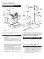
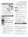
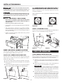
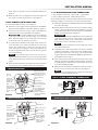
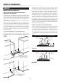
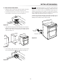
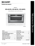
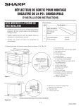
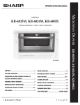
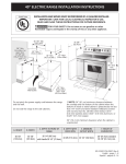
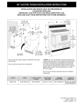
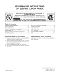
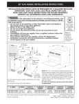
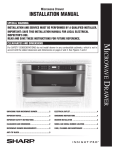
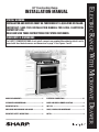
Installation Manual
SPECIAL WARNING
INSTALLATION AND SERVICE MUST BE PERFORMED BY A QUALIFIED INSTALLER.
IMPORTANT: SAVE this installation manual FOR LOCAL ELECTRICAL
INSPECTOR’S USE.
READ AND SAVE THESE INSTRUCTIONS FOR FUTURE REFERENCE.
Clearances & Dimensions
For SAFETY CONSIDERATIONS do not install a range in any combustible cabinetry which is not in
accord with the stated clearances and dimensions on page 2. See Figures 1 and 2.
Range Measurements.......................................2
Electrical connections................................. 3-5
Clearances and Dimensions...............................2
Model and Serial number Location.....................4
Important Notes..............................................2
Anti-Tip ..................................................... 6-7
Unpacking and Examining your range..................3
Care, Cleaning and Maintenance .......................7
Important Safety Instructions..........................3
Notes.............................................................8
Electric Range With Microwave Drawer
30" Freestanding Range
Installation Manual
Range Measurements
30"
minimum 30"
to bottom of
cabinet over
cooktop
29 7/8"
18"
to upper
cabinets
44 3/8±1/8"
backsplash
36 1/8"
to cooktop
surface
42"
drawer
open
6"
6 1/8"
6"
6 1/8"
27"
back to front
of doors
45 3/8"
oven door
open
36"
countertop
height
Maximum
depth of cord,
7 3/8"
plug and
receptacle box
is 4" to prevent
interference
with lower
oven.
30"
door width
Figure 1
4"
preferred electrical
outlet area
30"
opening width
Figure 2
To eliminate the risk of burns or fire by reaching over the
cooktop, cabinet storage space located above the cooktop should
be avoided. If cabinet storage is to be provided, the risk can be
reduced by installing a range hood that projects horizontally a
minimum of 5" beyond the bottom of the cabinets.
Figure 1 contains many range measurements for reference when
planning your kitchen and/or range location.
Clearances and Dimensions
• Provide adequate clearances between the range and adjacent
combustible surfaces.
Important notes to the installer
• Dimensions that are shown in Figure 2 must be used. Given
dimensions provide minimum clearance. There needs to be a
30-inch minimum clearance between the top of the cooking
surface and the bottom of unprotected wood or metal cabinets or
a 24-inch minimum when bottom of wood or metal cabinets are
protected by not less than a 1/4-inch flame retardant millboard
covered with not less than no. 29 msg sheet-steel, 0.015-inch
stainless steel, 0.024-inch aluminum or 0.020-inch copper. Note
that the gray shaded area on Figure 2 indicates the location for
the electrical receptacle/connection.
• Read all of the Installation Manual before installing the
range.
• Remove all packing material from the oven and drawer before
connecting the electrical supply to the range.
• Observe all governing codes and ordinances.
• Be sure to leave these instructions with the consumer.
Important notes to the consumer
• Contact surface must be solid and level. Pay special attention
to the floor. Be sure it is solid enough for the weight of the
range. Check that the floor covering is smooth and flat and that
it adheres to the sub-floor solidly.
Keep this manual with your Operation Manual for future reference.
• As when using any range generating heat, there are certain
safety precautions you should follow. These are listed in the
Operation Manual. Read all and follow carefully.
• Check location where the range will be installed for proper
electrical supply.
• Be sure your range is installed and grounded properly by a
qualified installer or service technician.
Installation Manual
• Before installing the range in an area covered with
linoleum or any other synthetic floor covering, make sure
the floor covering can withstand heat at least 90˚F (32.2˚C)
above room temperature without shrinking, warping or
discoloring. Do not install the range over carpeting unless
you place an insulating pad or sheet of 1/4-inch (0.64cm) thick
plywood between the range and carpeting.
Unpacking and Examining your Range
1 Remove all packing
materials from
inside the Microwave
Drawer and the oven
cav it y. D O NO T
R E M OV E T H E
WAV E G U I D E
COVER, which is
located on the top
of the Microwave
Drawer area.
Sealing Surface
Waveguide
Cover
Never leave children alone or unattended in the
area where an range is in use. As children grow, teach them the
proper, safe use of all ranges. Never leave the oven door open when
the range is unattended.
Sealing Surface
Stepping, leaning or sitting on the door or drawer
of this range can result in serious injuries and can also cause damage
to the range.
Microwave
2 Remove the feature
Drawer Cavity
sticker, if there is one.
Check the drawer for
any damage, such as misaligned or bent drawer, damaged drawer
seals and sealing surfaces, broken or loose drawer guides and
dents inside the drawer or on the front side of the drawer. If there
is any damage, do not operate the Microwave Drawer and contact
your dealer or a SHARP AUTHORIZED SERVICER.
• Do not store items of interest to children in the cabinets
above the range. Children could be seriously burned climbing
on the range to reach items.
• To eliminate the need to reach over the cooktop, cabinet storage
space above the cooktop should be avoided.
• Do not use the oven as a storage space. This creates a
potentially hazardous situation.
Important Safety Instructions
• Never use the range for warming or heating the room.
If the information in this manual is not followed
exactly, a fire or electrical shock may result causing property damage,
personal injury or death.
• Do not store or use gasoline or other flammable vapors and
liquids near this or any other range. Explosions or fires could
result.
• Reset all controls to the “off” position after using a
programmable timing operation.
• All Ranges can tip
• Injury to persons could result
When using the Self-Clean Feature:
• Install Anti-Tip bracket packed with Range
• Remove broiler pan, food and other utensils before
self-cleaning the oven. Wipe up excess spillage. Follow the
precleaning instructions in the Operation Manual.
• See Anti-Tip bracket Template for Installation Instructions
Electrical Connections
The installer or consumer is responsible for connecting the power
supply cord to the connection block located behind the back panel
access cover.
To reduce the risk of tipping the range, it must
be secured by properly installed Anti-Tip bracket packed with
the range.
This range may be connected by means of permanent “hard wiring”
(flexible armored or nonmetallic shielded copper or aluminum cable),
or by means of a power supply cord kit. Only a power supply cord kit
rated at 240 volts or 208 volts and 50 amperes and marked for use
with ranges shall be used. Cord must have either 3 or 4 conductors
to match electric receptacle. The power cord kit is not included so
must be purchase at an appliance store.
• This range must be electrically grounded in accordance with
local codes, or in their absence, with the National Electrical
Code ANSI/NFPA No. 70—latest edition in United States.
• The installation of ranges designed for manufactured (mobile)
home installation must conform with Manufactured Home
Construction and Safety Standard, title 24CFR, part 3280
[Formerly the Federal Standard for Mobile Home Construction
and Safety, title 24, HUD (part 280)] or when such standard
is not applicable, the Standard for Manufactured Home
Installation 1982 (Manufactured Home Sites, Communities
and Setups), ANSI Z225. 1/NFPA 501A- latest edition, or with
local codes in United States.
For mobile homes, new installations, recreational vehicles or areas
where local codes do not permit grounding through neutral, a 4 conductor power supply cord kit rated at 240 volts or 208 volts minimum,
50 amperes and marked for use with ranges should be used.
• Make sure the wall coverings and the cabinets around the range
can withstand the heat generated by the range.
Terminals on end of wires must be either closed loop or open-end
spade lugs with upturned ends. Cord must have strain-relief clamp.
The range connection opening should be 1 3/8-inches.
Installation Manual
3 & 4-Wire electrical wall receptacle types &
recommended mounting orientation on wall
Risk of fire or electrical shock exists if an incorrect size range cord kit is used, or the installation instructions are
not followed precisely and/or a strain relief clamp is not used.
Figure 5A illustrates 4-wire receptacle required for new and
remodeled installations.
Do not loosen the nuts which secure the factory-installed range wiring to the terminal block while connecting range.
Electrical failure or loss of electrical connection may occur.
Figure 5B illustrates 3-wire receptacle that is allowed for existing
installations.
Electrical Shock Hazard
• DISCONNECT POWER TO THE CIRCUIT BREAKER
OR FUSE BOX BEFORE MAKING THE ELECTRICAL
CONNECTION.
• Electrical ground is required on this range.
• Do not connect to the electrical supply until range is permanently
grounded.
• This range must be connected to a grounded, metallic,
permanent electrical system or the grounding connector of the
power cord should be connected to the grounding terminal or
wire lead on the range.
• Failure to heed these warnings could result in a fire, personal
injury or electrical shock.
4-wire wall receptacle (14-50R)
Figure 5A
3-wire wall receptacle (10-50R)
Figure 5B
Access to Terminal Block
Loosen screw on rear access cover and pull down as illustrated in
Figure 6 to access terminal block wiring connection.
strain relief clamp
screw
Rating plate
Figure 6
model and serial number location
Power Cord Connections
The rating plate, including model and serial number, is located on
the faceplate behind the Microwave Drawer front.
4-Wire Connection instructions
208/240 Volt Connection Instructions
Before wiring the range, review the suggested power source location
drawing in Figure 2. If connecting to a 4-wire electrical system for a
new branch-circuit or mobile home use a 4-wire connection.
The range can be set for 208V or 240V. The voltage setting for your
range is pre-set at 240V from the factory. Follow these steps to
change the voltage setting.
1 Follow the power supply cord kit manufacturer’s Installation
Instructions and install the strain relief clamp on the cord. See
Figure 7.
1 Locate the voltage switch on the lower back side of the range.
2 Remove the screw and rotate the switch plate 180˚ as indicated
in the Figure 3.
2 Connect the end connectors for line 1, line 2 and neutral and
tighten securely to the terminal block. See Figure 8.
208V
240V
3 Reinsert the switch plate and replace screw as indicated in Figure
4. The voltage setting is indicated by the visible marking.
180˚
screw
Figure 7
IMPORTANT DO NOT LOOSEN the factory installed nut
connections which secure the range wiring to the terminal
block. Electrical failure or loss of electrical connection may
occur if these 3 nuts are loosened or removed.
screw
3 You must disconnect the ground strap. Remove the factory
installed ground screw and plate to release the copper ground
strap from the frame of the range. Cut and discard the copper
ground strap and plate. KEEP the ground screw. See Figure 8.
Figure 3
4 Connect the green ground wire lead with the eyelet to the frame
of the range with the ground screw using the same hole in the
Figure 4
Installation Manual
frame where the ground screw was originally installed. See
Figure 8.
5 Make sure all screws are tightened securely and replace the
rear access cover and secure with screw. See Figure 6.
3 & 4-WIRE PERMANENT WIRE CONNECTIONS
3-Wire Connection Instructions 1 Follow the manufacturer’s Installation Instructions for installing
the strain relief clamp.
3–wire permanent connection – follow steps 1, 2 and 5 below. 4–wire permanent connection – follow all steps below.
Before wiring the range, review the suggested power source location
drawings in Figure 2. If connecting to a 4-wire electrical system:
For existing installations ONLY, refer to Figure 9.
1 Follow the power supply cord kit manufacturer’s Installation
Instructions and install the strain relief clamp. See Figure 7.
2 Connect the end connectors for line 1, line 2 and neutral and
tighten securely to the terminal block. See Figure 9.
IMPORTANT DO NOT LOOSEN the factory installed nut
connections which secure the range wiring to the terminal
block. Electrical failure or loss of electrical connection may
occur if these 3 nuts are loosened or removed.
2 Strip insulation away from the ends of the permanent wiring
for line 1, line 2 and neutral; also strip ground wire on 4-wire
connections. Tighten all 3 or 4-wire leads to the terminal block.
Follow wire locations shown in Figure 10.
IMPORTANT DO NOT LOOSEN the factory installed nut
connections which secure the range wiring to the terminal
block. Electrical failure or loss of electrical connection may
occur if these 3 nuts are loosened or removed.
3 A ground strap is installed on this range which connects the
center terminal of the neutral terminal block to the range
chassis. The ground strap is connected to the range by the
center, lowest screw. See Figure 9. The ground strap must not
be removed unless National, State or Local Codes do not permit
use of a ground strap.
NOTE: For 3-wire permanent connection skip steps 3 and 4
and continue with step 5.
3 Disconnect the ground strap. Remove the factory installed
ground screw and plate to release the factory installed copper
ground strap from frame of the range. Cut and discard the
copper strap from the terminal block. KEEP the ground screw,
ground plate and go to step 4.
NOTE: If the ground strap is removed for any reason, a
separate ground wire must be connected to the separate ground
screw attached to the range chassis and to an adequate ground
source.
4 Connect the green ground wire lead to the frame of the range
using the ground screw and plate as shown in Figure 11. Be sure
to install using the same hole in the frame where the ground
screw was originally installed.
4 Make sure all connections are tightened securely and replace
the rear access cover and secure with screw. See Figure 6.
5 Make sure all connections are tightened securely and replace
the rear access cover and secure with screw. See Figure 6.
4-Wire Connection
Connect
line 1 here.
Cut ground
strap. Discard
ground strap
and ground
plate.
For 3 & 4-Wire Permanent Connections
Terminal block
ite
ck
gre
en
Figure 8
red
wh
la
b
Connect green
insulated copper
ground wire with
ground screw
here.
NOTE: Non-terminated field wire compression connections
must be set at approximately 90 in./lb.
Note: Install strain
relief clamp. Center or
white wire must always
be attached to the
center terminal on
block.
Connect line 2 here.
Connect neutral (white
or center) here.
A user supplied strain
relief clamp must be
installed at this
location. It requires 1
3/8" (3.5 cm) diameter
cord kit hole.
terminal
block
line 2
line 1
terminal
block
neutral
line 1
neutral
ground strapground
screw
ground plate
Figure 10
ground
3-Wire Connection
4-Wire Permanent
Connection only
screw
ground
plate
Terminal block
Connect line
1 here.
Ground strap
Note: Install strain
relief clamp. Center
must always be
attached to the
center terminal on
block.
Figure 9
ground strap
line 2
ground plate
Connect line 2 here.
ground
plate
Connect neutral
here.
ground
screw
A user supplied
strain relief clamp
must be installed
at this location. It
requires 1 3/8"
(3.5 cm) diameter
cord kit hole.
ground
screw
ground
wire lead
Figure 11
proper
ground
ground
for 4-wire
wire lead
permanent
proper ground
for 4-wire
permanent
Installation Manual
Mark the floor or wall where left or right side of the range will be
located. If rear of range is against the wall or no further than 1
1/4 -inches from wall when installed, you may use the wall or floor
mount method. See Figure 13. If molding is installed and does not
allow the bracket to fit flush against the wall, remove molding or
mount bracket to the floor. For wall mount, locate the bracket by
placing the back edge of the template against the rear wall and the
side edge of template on the mark made referencing the side of the
range. Place bracket on top of template and mark location of the
screw holes in wall. If rear of range is further than 1 1/4-inches from
the wall when installed, attach bracket to the floor. See Figure 14. For
floor mount, locate the bracket by placing back edge of the template
where the rear of the range will be located. Mark the location of the
screw holes, shown in template.
Anti-Tip
NORMAL INSTALLATION STEPS
Anti-Tip bracket Installation Instructions Important Safety Warning
To reduce the risk of tipping of the range, the range must be secured
to the floor by properly installed Anti-Tip bracket and screws packed
with the range. Failure to install the Anti-Tip bracket will allow the
range to tip over if excessive weight is placed on an open door or if
a child climbs upon it. Serious injury might result from spilled hot
liquids or from the range itself.
If range is ever moved to a different location, the Anti-Tip bracket
must also be moved and installed with the range. Instructions are
provided for installation in wood or cement fastened to either the floor
or wall. When installed to the wall, make sure that screws completely
penetrate dry wall and are secured in wood or metal. When fastening
to the floor or wall, be sure that screws do not penetrate electrical
wiring or plumbing.
2 Drill Pilot Holes and Fasten bracket
Drill a 1/8-inch pilot hole where screws are to be located. If bracket
is to be mounted to the wall, drill pilot hole at an approximate 20
degree downward angle. If bracket is to be mounted to masonry or
ceramic floors, drill a 5/32-inch pilot hole 1 3/4-inches deep. The
screws provided may be used in wood or concrete material. Use a
5/16 -inch nut-driver or flat head screwdriver to secure the bracket
in place.
1 Locate the bracket - Using the Template
The bracket may be located on either the left or right side of the
range. Refer to figure 12b to locate the bracket if template is not
available.
FASTEN BRACKET (WALL OR FLOOR MOUNTING)
leveling leg
max 11/4"
wall mount
wall plate
floor mount
Anti-Tip bracket
Figure 13
15"
FASTEN BRACKET (FLOOR MOUNTING ONLY)
15"
more than
11/4"
leveling leg
The edge of the template
should be aligned with the left
or right edge of the range.
wall
Figure 12A
floor mount
Figure 14
13 3/8"
13 3/8"
13 3/8" from the center of
the wall opening to the edge
of the backet.
Figure 12B
Anti-Tip bracket
Installation Manual
A minimum clearance of 1/8-inch is required between
the bottom of the range and the leveling leg to allow room for the
bracket. Use a level to check your adjustments. Plug range into
properly prepared electrical receptacle or if hard wired, check that
it was completed properly. Check floor condition for evenness and
stability. Slide range back into position. See Figure 18.
3 Level and Position Range
NOTE:
• Measure from the countertop to the floor height to determine
the height that the back of the range needs to be set at.
• Loosen legs and lock nuts to set level of the range. (Note that
the lock nuts are only on the rear feet). See Figure 15.
Visually check that rear leveling leg is inserted into and fully secured
by the Anti-Tip bracket by looking underneath the range with a
flashlight and carefully attempt to tilt it forward.
Figure 15
Range Leg
Lock Nut
(Rear leg only)
• Adjust the back leveling legs with an adjustable wrench or pliers.
Measure from the floor to the top of the cooktop glass (X) and
adjust the legs to match the measurement (Y) taken from the
cutout. See Figure 16.
1 5/8" to edge
of bracket
Range Slide
(Y")
floor to
top of
countertop
Figure 18
(X")
floor to top
of cooktop
glass
Figure 16
• After leveling, tighten the lock nuts on the rear to prevent the
feet from turning when sliding into position. See Figure 17.
Figure 17
Installation Manual
Care, Cleaning and Maintenance
Refer to the Operation Manual for cleaning instructions. If removing
the range is necessary for cleaning or maintenance, disconnect the
electrical power supply. If the electrical supply is inaccessible, lift
the unit slightly at the front and pull out away from the wall. Pull
only as far as necessary to disconnect the electrical supply. Finish
removing the unit for servicing and cleaning. Reinstall in reverse
order making sure to level the range and check electrical connections.
See pages 2 and 3 for proper anchoring instructions.
Before You Call for Service
Read the BEFORE YOU CALL and operating instruction sections
in your Operation Manual. It may save you time and expense. The
list includes common occurrences that are not the result of defective
workmanship or materials in this range.
Refer to your Operation Manual for our service address. Sharp's
toll-free telephone number is 1-800-BE-SHARP (1-800-237-4277).
Please call or write if you have inquiries about your range product
and/or need to order parts.
NOTE: Please do not open or close the lower oven door for 30
seconds after plugged in.
SHARP ELECTRONICS CORPORATION
Sharp Plaza, Mahwah, New Jersey 07430-2135
Printed in USA
TINSEB 4 3 8 MRR1