1
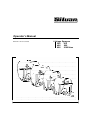
Operator’s Manual
MANLINK-1 REV G 16/10/2006
Linkage Sprayers
200
300
400
600
800
1000 litres
Introduction
Silvan is an Australian owned company specialising in the supply of crop protection equipment to
primary producers. A leader in the design of agricultural sprayers, the company was established in 1962
and has grown to become the largest manufacturer and supplier of crop protection equipment in
Australia.
This manual covers all types of linkage sprayers manufactured by Silvan, within the tank capacity range
of 200 to 1000 litres, including sprayers of the Slimline, Pasturepak and Prolink series. Information on
the various types of spray booms and associated equipment used with these linkage sprayers is
included.
Silvan linkage sprayers and associated equipment are designed and manufactured to provide a high
standard of performance and safety and incorporate innovative features. To ensure continued efficient
performance and safe operation, you need to read this manual thoroughly and fully familiarise yourself
with all aspects of your sprayer’s operation, maintenance and safety procedures.
Now that you’re a proud Silvan owner, all our services and dealer support are available to you should
you need them. We assure you of our best attention at all times.
No liability can be accepted for any inaccuracies or omissions in this publication, although due care
has been taken to make it as complete and accurate as possible.
The information, illustrations and technical data were considered to be correct at the time of
preparation.
In accordance with our policy of continuous development Silvan Australia Pty. Ltd. reserves the right
to make changes at any time without notice.
Page 1
Contents
Page
Warranty
About Your Warranty
2
New Product Warranty Policy
3
Warranty Registration Form
Inside Rear Cover
Safety Information
4
Specifications
7
Operation
Attaching to the tractor and PTO drive
8
Starting the Sprayer
8
Control Units - 2 and 3 way, Single lever, Silvamatic
9
Spray Booms
11
Boom Filters, Spray Guns and Hose Reels
12
General Spraying Information
When to spray, field patterns, droplet size
13
Nozzle height, application rate, ground speed
13
Calibrating the Sprayer
Testing, verifying calibration, nozzle maintenance
14
Nozzle selection
15
Optional Equipment
Foam markers, Boom accessories, Dual stage gauge
17
Cabin control units
18
Lubrication and Maintenance
19
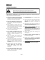
About Your Warranty
Silvan Australia Pty. Ltd. welcomes any warranty
repair and apologises for any inconvenience
caused. See the next page for the statement of the
warranty coverage offered by Silvan. The following
information will assist your understanding of
warranty procedures.
Warranty Repair Site
The warranty provides for repairs to be carried out at
the servicing dealer’s normal place of business. An
owner may elect to have repairs carried out at his
own residence but, whilst Silvan will accept the actual
repair cost of the failed component(s), the travelling
costs will not be covered under warranty.
Any authorised Silvan dealer service outlet can
perform warranty repairs, however, we recommend
that such repairs be carried out by the Dealer from
whom you bought the machine.
Items Not Covered By Warranty
The warranty does not allow for the cost of the
following items. These are the responsibility of the
owner.
Most warranty repairs are handled routinely, but
sometimes requests for repairs cannot be accepted
under warranty. Normal wear and tear is not
covered by warranty nor does warranty apply if a
machine fails prematurely and that failure can be
attributed to abuse or neglect.
1) Labour to travel to and from a broken-down
machine or for any distance charges.
2) Labour premiums that might apply for any repairs
that are made outside the dealer’s normal
business hours.
3) Transportation costs of the machine to and from
the service outlet.
4) Freight costs to get parts to and from the service
outlet.
5) Telephone and fax calls made by the owner in
connection with the warranty repair.
Whilst Silvan will abide by its warranty policy under
all genuine circumstances, we must emphasise that
such can only apply when our equipment has been
used in applications for which it was designed and
manufactured and that a reasonable degree of care
and common sense has been exercised by the
operator.
Page 2
New Product Warranty
The Silvan
Warranty
This warranty is the only warranty applicable to Silvan new products ('Products') and, to the
maximum extent permitted by law, is expressly in lieu of any other conditions or warranties
expressed or implied in relation to the Products.
Subject only to legislative obligations to the contrary, Silvan shall not be liable for incidental
or consequential damage resulting from ownership or use of a Product.
Silvan does not authorize any person to create for it any other obligation or liability in
connection with these products.
Silvan warrants its authorised Dealer, who in turn warrants the original purchaser (owner) of each
new Silvan product that it will repair or replace the product, or, pay the cost of repair or replacement,
as determined by Silvan without charge for labour or any defective or malfunctioning parts in
accordance with the warranty limitations and adjustment schedule below.
The warranty period begins on the date the product is delivered to the first retail purchaser for a
period of 12 months
This Warranty Covers
Only conditions resulting directly from defects in workmanship or material under normal use and
service.
Warranty Exclusions
The Warranty does not cover:
Conditions resulting from misuse, use of incompatible chemicals, exceeding machine
specifications including overloading, impact damage, negligence, accidental damage or
failure to perform recommended maintenance services.
Any product which has been repaired by other than an authorised Silvan service outlet in a
way which, in the sole and absolute judgement of Silvan, adversely affect its performance
or reliability.
The replacement of maintenance items such as diaphragms, batteries, V belts and ground
engaging components, etc.
Loss of time, inconvenience, loss of use of the product liability to third parties or any other
consequential damages.
Incidental costs associated with a warranty repair including any travel costs, out of hour’s
labour charges, cleaning costs, transportation costs, freight costs or any communication
costs.
The repair of a defective product qualifying under this warranty will be performed by any authorised
Silvan service outlet within a reasonable time following the delivery of the product, at the cost of the
owner, to the service outlet’s place of business. The product will be repaired or replaced, using
new parts supplied by Silvan. Silvan, in its absolute discretion, may choose to pay the cost of
replacement or repair of the product.
The owner is responsible for the performance of regular maintenance services as specified in the
Owner/Operator Manual applicable to the product. Failure to carry out regular maintenance may
invalidate warranty
Page 3
Safety Information
Before operating the sprayer read the following safety instructions.
Failure to comply with these warnings may result in serious injury or death.
Whilst your Silvan linkage sprayer has been designed and manufactured to incorporate all necessary
safety features it is essential that any person who operates or works on the machine is aware of the
safety precautions that should be exercised.
S This sprayer is designed and manufactured
solely for the purpose of applying agricultural
chemicals to crops. Under no circumstances
should it be used for any other purpose.
S Before using this sprayer carefully read and
ensure you understand the contents of this
manual and any other manual supplied with
the sprayer.
S Before operating the sprayer read all the
safety warnings which are carried on various
parts of the machine. Refer to the next page
for the wording of these warnings.
S Never allow an inadequately trained person
to attach or operate the sprayer.
S Do not operate the sprayer whilst wearing
loose clothing, unrestrained long hair,
jewellery or anything which could become
entangled in rotating components or limit
your vision.
S Wear ear protection when operating the
sprayer on a tractor which is not fitted with a
sound proofed cabin.
S Ensure the linkage capacity of the tractor is
suitable for the loaded mass of the sprayer.
Refer to the tractor operator’s manual for
safe working loads and relevant tractor safety
instructions.
S Exercise extreme care when operating in
hilly or uneven terrain to ensure proper
stability. Refer also to the tractor
manufacturer’s
operating
and
safety
instructions .
S Do not operate the sprayer without all the
tractor and sprayer safety shields in place.
Carefully check that PTO and driveline
shields are correctly installed.
Page 4
S Do not operate the sprayer at speeds greater
than 540 PTO rpm.
S Stop the tractor PTO, apply the parking brake
and switch off the tractor engine before
approaching the sprayer or performing any
work on it.
S Disconnect the PTO shaft at the tractor and
ensure the sprayer is properly supported before
performing any maintenance work.
S Before use of any chemicals refer to the
chemical manufacturer’s label and safety
instructions for safe handling procedures and
correct method of use. Always use the
recommended personal protective clothing and
safety equipment.
S Always wear gloves when removing and
cleaning filters.
S Dispose of empty chemical containers in
accordance with the instructions supplied by
the chemical manufacturer.
S Ensure that all operators and associated
personnel are familiar with the legal regulations
and codes of practice that apply to the safe use
and storage of spray chemicals.
S Do not enter the sprayer tank under any
circumstances. If service is required contact
Silvan for correct maintenance procedures.
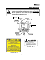
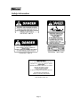
Safety Information
The location and wording of the safety decals fitted to Silvan linkage sprayers
is shown below. It is important that all operators read and follow the
information on all safety decals before operating the sprayer. Failure to comply
with these warnings could result in serious injury or death. Safety decals
should be kept clean and legible at all times. If any decals are missing or
unreadable they should be replaced by ordering new decals from your Silvan
dealer using the part numbers shown below.
DEC 13, 200L
ONLY
DEC 48
DEC 13
DEC 07
DEC 12
DEC 10
399 14 1000
DECAL POSITIONS
200, 300, 400, 600, 800 AND 1000 LITRE SPRAYERS
Part Number DEC 13
Part Number DEC 48
Page 5
Safety Information
Part Number DEC 10
Part Number 399 14 1000
Part Number DEC 12
IMPORTANT
P.T.O. SPEED MUST NOT EXCEED 540 R.P.M.
ENSURE P.T.O. SHAFT IS CORRECT LENGTH
EACH DAY
GREASE TELESCOPIC TUBE ON P.T.O. SHAFT.
GREASE UNIVERSAL JOINTS.
CLEAN SUCTION STRAINER.
CHECK PUMP OIL LEVEL.
FLUSH OUT PUMP WITH WATER AFTER USE.
FOR GENERAL MAINTENANCE,
REFER TO INSTRUCTION BOOKS.
Part Number DEC 07
Page 6
Specifications
Tanks
Constructed from Polytuff impact resistant
polyethylene.
Capacity 200, 300, 400, 600, 800 or 1000 litres
with calibrated level indicator.
Screw down lid of 255mm diameter with basket
strainer.
Continuous by-pass agitation returning to the
tank.
Pumps
Constant displacement oil backed diaphragm
pump of varying size depending on sprayer
specification. Output at maximum permitted 540
PTO rpm with maximum operating pressure as
shown below.
Pump No.
BP 20/15
BP 60/20
BP 125/20
APS 41
Output
l/min
19
58
117
38
Max. Pressure
Bar
psi
15
218
20
290
20
290
40
580
Spray Booms
Field
Galvanized steel truss.
6 or 8 m.
Three section horizontal fold.
Fieldmaster
Galvanized steel truss with nozzle protection.
10 or 12 m.
Three section horizontal fold.
Double fold outer arms.
Suspension and height control.
IMM Hydraulic Boom
6m Devil
Hydraulic vertical fold boom
Vine Boom
8 or 12 jet.
Adjustable telescopic arms.
Adjustable brass nozzles.
Olive Boom
7 jet
One sided Olive boom.
Sprayguns
Topline On/off trigger.
Maximum pressure 5000 kPa.
Triam44
Trigger controlled spray pattern.
Maximum pressure 5000 kPa.
Controls
Manual by-pass to tank.
Screw type pressure regulator.
Glycerine filled pressure gauge. Dual stage on
some models.
2 to 6 boom outlets depending on sprayer type.
Single lever on/off control on some models.
Pressure compensated valves on some models.
Longranger
Two handed grip.
Maximum pressure 5000 kPa.
Filtration
Two stage with removable elements on all units.
Three or four stage if fitted with optional boom
section filters.
Standard mesh shown. Alternatives available.
Tank lid strainer
18 mesh.
Suction line filter
50 mesh (blue).
Boom nozzle strainers
50 mesh.
Boom section filters
100 mesh (red).
L
W
H
Sprayer (w/out boom)
200 litre
950 760 1070
300 litre
1200 740 1070
400 litre
1020 740 1330
600 litre
1160 900 1350
800 litre
1330 980 1370
1000 litre
1650 1250 1370
Note: Max pump pressure only, max operating pressure of
sprayer will depend on type of control valve fitted.
Frame and Hitch
Heavy duty galvanized steel construction.
Reversible Category 1 & 2 linkage pins on 200,
300, 400, 600 and standard 800 litre models.
Category 2 linkage pins on 800 Heavy Duty and
1000 litre models.
Optional Equipment
Foam Marker - 14L One Sided, 30L Bubbler or
30L PaddockMarker.
Boom - End Taps, Fence Line Kit, Skimmers.
- Solenoid valves with cabin control unit.
Page 7
Dimensions and Weights
Length L, width W, height H, all in (mm).
Mass M (kg) with tank empty. To calculate gross
mass add 1 kg/litre capacity (eg. 200L = 200kg).
Boom (folded)
Field
6m
8m
Fieldmaster 10m
12m
IMM
6m
2067
2067
2575
2575
2500
M
65
70
75
91
120
170
Operation
Attaching to the Tractor
Most Silvan linkage sprayers are equipped to fit
tractors with either Category 1 or 2 linkages. The
inner end of each lower linkage pin is Category 1
diameter and the outer end is Category 2. The lower
holes in the top connection plates are Category 1
diameter and the upper holes are Category 2. The
800 litre heavy duty and 1000 litre models are
equipped for Category 2 only.
Remove the PTO shaft from the sprayer by
depressing the locking pin. Lower the tractor linkage
and attach it to the sprayer’s lower hitch pins of the
appropriate category, then connect the upper linkage
arm using the tractor’s linkage pin. Secure all linkage
pins with one of the tractor’s lynch pins. Raise the
tractor linkage to the desired spraying height and level
the sprayer by adjusting the length of the top linkage
arm.
Clean and grease the splines on the tractor and
sprayer PTO stub shafts and install the PTO shaft
making sure that the spring loaded locking pins
engage in the interference grooves of both stub
shafts. Ensure that the PTO shaft guards are attached
to the sprayer and tractor.
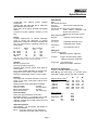
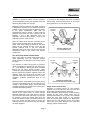
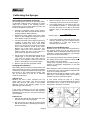
PTO Shaft Length
Note: Upon delivery of a new PTO driven sprayer
it is the selling dealer’s responsibility to install
and set the PTO driveshaft to the correct length,
as part of the installation service. The following
information is provided for reference.
Set the linkage height so that the ends of the two
shafts are at their closest distance. Install the PTO
shaft making sure that there is at least 25mm of
telescopic travel remaining between the male and
female sections. Raise and lower the sprayer to check
that the telescopic tubes of the PTO overlap by
approximately 1/3rd of their length, and not less than
150mm, in all operating positions.
If the PTO shaft must be shortened cut equal
amounts from both male and female shafts and
safety covers. Carefully remove all burrs and swath
then clean and relubricate before reassembling.
Starting the Sprayer
When starting the sprayer for the first time conduct
a trial run using water to familiarise with the
operation of the controls and to check that all
systems are functioning correctly without any
leakage.
When filling the tank ensure that the basket strainer
is in place and clean. Close the lid securely after
filling.
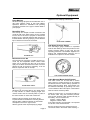
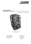
Stop Valve Cap
‘O’ Ring
Element
SUCTION FILTER COMPONENTS
The suction filter is fitted with a shut-off valve which
closes automatically when the valve cap is screwed
off. This allows the filter cover to be unscrewed and
the element to be removed for cleaning while there
is fluid in the tank. Gloves should be worn when
handling the filter.
When the sprayer is operating the valve must be
fully screwed in to open the shut-off valve and allow
fluid to pass through the filter. Directional arrows
are moulded into the valve cap to show the opening
and closing operation.
Check the oil level of the diaphragm pump and if
necessary top up with SAE 20-40 multigrade engine
oil. Refer to the pump instruction manual for further
details.
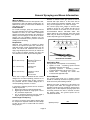
Various types of control units are fitted to Silvan
linkage sprayers - refer to the following pages for
the operating details for each type - but the general
operating information below is common to all
sprayers.
Before engaging the PTO, the by-pass control
should be moved to the by-pass position and the
outlet valves should be closed, using either the
individual valve levers or the single lever depending
upon control type.
Engage the PTO slowly and allow the sprayer to
run in by-pass mode. Once the pump is primed
increase the tractor speed to 540 PTO rpm.
The by-pass lever can then be moved to the
CORRECT PTO SHAFT LENGTH
Page 8
1
Operation
operating or pressure position and the pressure
can be adjusted by turning the regulator knob and
observing the reading on the gauge.
Depending upon the particular type fitted, the pump
is designed to operate up to a maximum pressure
of either 15 bar (218 psi) or 20 bar (290 psi). Refer
to the pump identification plate and the
specifications page for details. In either case the
pressure range used for boom spraying will be
between 1 and 4 Bar depending upon the
application rate and other factors - refer to the
Calibration section of this manual.
Open the outlet valves that are connected to the
boom or other spraying device to start spraying.
Under most boom spraying conditions, the PTO
speed can be reduced and the pump will still
provide sufficient flow to suit the particular
application rate being used. This will save fuel and
unnecessary wear on the tractor and sprayer
components.
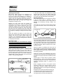
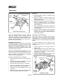
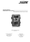
If you wish to stop spraying but leave the tractor
PTO running, close the outlet valves “C” and move
the by-pass lever “A” to by-pass mode.
Pressure
regulator
“B”
Outlet
valves
“C”
By-pass
control
“A”
TWO WAY CONTROL UNIT
Used with BP 20/5 pump
Two and Three Outlet Control Units
Either a two outlet or a three outlet control unit is
used, depending upon the particular sprayer
model. However, the operation of all control units is
the same.
The selection of either the by-pass or pressure
mode of operation is controlled by the rotary lever
“A” - refer diagrams. Moving the lever clockwise
through its full travel selects by-pass, which
reduces the pumps operating pressure by allowing
liquid to bypass the pressure regulator. Note, this
operation does not fully shut-off the flow to the
individual outlet taps. Moving the lever full anticlockwise re-directs pressurised fluid to the
outlets.
System pressure is regulated by turning the red (or
on some valves black) knob “B” and observing the
reading on the pressure gauge. Turning the knob
clockwise increases the pressure and turning anticlockwise decreases pressure.
Fluid is directed to the boom lines or other spraying
devices by the outlet valves “C” which may be
operated individually. The outlet valves of the two
way control are open when the levers is in line with
the direction of flow and closed when they are
across the direction of flow. The outlet valves of the
three way control are open when the levers are
vertically down and closed when they are vertically
up. Refer diagrams.
Page 9
By-pass
control
“A”
Pressure
regulator
“B”
open
Outlet
valves
“C”
Outlet
valve
“C”
THREE WAY CONTROL UNIT
Used with BP 60/20 and BP 125/20 pumps
Single Lever Control Unit
Operation of by-pass control “A” and pressure
regulator “B” is the same as that of the two and
three outlet controls previously described.
Fluid is directed to the boom lines or other spraying
devices by four outlet valves which may be
operated individually or as a group. The individual
valves are open when levers “C” are vertically
down and closed when vertically up. Raising the
single lever ”D” and swinging it over to the other
side of the valve opens the flow to all valves and
swinging it back closes the flow.
Operation
Single Flow Control “D”
swing over to open
all valves
Outlet
Valves
“C”
open
By-pass
Control
“A”
Outlet
Valves
“C”
Pressure
Regulator
“B”
Operation
1. Set the by-pass control to pressure mode
(lever “A” down).
2. Adjust the maximum system pressure with
pressure regulator “B” until the gauge reads
approximately 15 Bar.
3. Adjust the spraying pressure with regulator “D”
until the pressure drops to your required
operating pressure (turn knob anti-clockwise to
reduce pressure).
4. Open the individual outlet valves to direct fluid
to the required sections of the boom (set levers
“E” vertically up).
5. Once the required outlets have been selected,
spraying can be started and stopped by
moving the by-pass lever “A” between pressure
and by-pass positions.
SINGLE LEVER CONTROL UNIT
Once the required outlets have been selected
using the individual valves, spraying may be
started and stopped by using the single lever. If
you wish to stop spraying but leave the tractor PTO
running, close the single lever and move the bypass lever to by-pass mode.
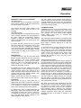
Silvamatic Control Unit
The Silvamatic control is a pressure compensating
unit which provides a constant flow rate if the
tractor PTO speed changes by up to 15%, thus
maintaining a constant application rate. It also
maintains constant pressure when individual outlet
valves are opened or closed.
The unit can be supplied with either four or six
outlets and includes a self cleaning filter and a
suck back device. A dual stage pressure gauge is
fitted to facilitate accurate setting of spraying
pressure at low or high readings.
Preliminary Adjustments Prior to Starting
1. Set the by-pass control to by-pass mode (lever
“A” up).
Adjusting the Outlet Calibrators
Each outlet valve has a calibrator which, after the
initial setting, allows boom sections to be operated
independently or in combination without altering
the pressure as the individual outlets are opened or
closed.
To set the calibrators run the sprayer at the
required spraying pressure and adjust each outlet
as follows:
1. Note the pressure on the gauge when the
outlet is open.
2. Close the outlet and adjust the calibrator “E”
until the pressure is the same as in 1. above
(screwing the calibrator out decreases the
pressure and vice versa).
3. Once set, no further adjustment need be made
unless the boom nozzles are changed.
By-pass
Control
“A”
Self Cleaning Filter
Remove U Wire
Calibrator
“E”
2. Set the general pressure regulator to minimum
(turn knob “B” fully anti-clockwise).
3. Close all outlet valves (levers “C” horizontal).
Outlet
Valve
“C”
4. Set the compensating pressure regulator to
maximum (turn knob “D” fully clockwise).
5. Check that all outlet calibrators “E” are fully
screwed in.
6. Start the sprayer, which will operate without
pressure and by-pass all fluid to the tank.
Page 10
Maximum
Pressure
Regulator
“B”
Spraying
Pressure
Regulator
“D”
SILVAMATIC CONTROL
Operation
Silvamatic Control Unit (continued)
Suck Back Device
The Silvamatic control incorporates a suck back
device which operates on all open outlets while
the selector lever is in by-pass.
This prevents the boom nozzles dripping if the
tractor PTO is running while the unit is not
spraying.
Self Cleaning Filter
A self cleaning filter is incorporated in the control
unit to remove impurities from fluid pumped to
the boom. While the compensating pressure
regulator is operating, the filter is self cleaning
and the impurities which are removed are sent
back to the tank.
To inspect the filter, remove the two U shaped
wires that retain the compensating return hose
and remove the filter. If cleaning is necessary
use a soft brush. When reinstalling the filter take
care that the pointed end is towards the outside
of the control unit. Refer to the diagram on the
previous page
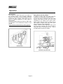
Spray Booms
A variety of booms may be used with Silvan
linkage sprayers depending upon the model and
field application. All have stainless steel
spraylines fitted with non-drip fan jet nozzles.
Booms are part of the standard equipment on
some models or in other cases they may be
installed by the dealer or owner.
On all types of boom, the setting of the correct
operating height is most important to achieve a
uniform spraying pattern. This needs to be at a
height above the target which will achieve 50%
overlap of the spray from adjacent nozzles - refer
Calibration section of this manual.
Always ensure that the boom is unfolded in a
safe area where it will not foul any other objects.
Field Boom
Field booms of 6 or 8 metre width are of
galavanized steel truss construction. The three
section fold allows the outer arms to break back
if an obstacle is contacted and automatically
return to the operating position when passed.
For transport the boom is folded horizontally by
swinging the outer arms rearwards through 1800
until against the fixed centre section, where they
are retained by the action of the hinge springs.
The arms are simply folded outwards to the
spraying position when required.
The rear uprights of the sprayer frame include a
series of holes to enable the boom to be attached at
a height suitable for the tractor size and spraying
application. Final spraying height is regulated by use
of the tractor linkage control.
FieldMaster Boom
FieldMaster booms in 10 and 12 metre widths are of
galvanized steel truss construction with a deep front
leg on the boom section to protect the spray nozzles
from damage. The three section boom features
double folding outer arms for compact and
convenient transporting.
The suspension system operates in the spraying and
transport positions through a parallelogram linkage
with tension springs and shock absorbing dampers.
Boom height is manually adjusted by a crank and
cable mechanism.
To fold the boom for transport, swing the outer arm
up and over, on to the support saddle of the inner
arm. Swing the inner arm horizontally rearwards
through 180 degrees until it rests across the centre
section, where it will be held by the action of the
spring in the hinge. Repeat for the other side.
Reverse the process to return the boom to the
operating position.
Adjusting Spraying Height
To adjust the spraying height first set the sprayer at
the approximate height with the tractor linkage then
adjust the boom lift. Insert a suitable bar through the
holes in the winch shaft on the right hand side of the
boom support. Lift the locking pawl from the ratchet
and wind the winch shaft to the required boom
height. Reset the locking pawl to hold the boom in
position then remove the bar from the winch shaft.
Check that the boom is horizontal. If levelling is
needed this can be done by adjusting the length of
the lifting cables. Lower the boom to minimum height
and fully unwind the cables. Remove the U-clamp
from the cable on the side to be raised, adjust the
cable length and retighten the clamp. Raise the boom
and check whether it is level.
The boom lift requires little maintenance but care
should be taken to ensure that the linkage arms are
not allowed to become loose, allowing sideways
movement of the boom. The lock nuts should be
kept sufficiently tight to eliminate side clearance
without the linkage binding. If the boom height setting
restricts suspension travel, then the suspension
assembly will have to be raised or lowered on its
mountings.
Page 11
Operation
Boom Filters
The Padboom is fitted with three in-line filters on
the mounting frame, each providing additional
filtration to one section of the boom before the fluid
reaches the spray nozzles. These filters may be
fitted as optional equipment on other types of
Silvan booms.
Unscrew the filter bowls and clean the filters daily
as described in the maintenance section of this
manual.
Avoid chemical contamination by wearing gloves.
Spray Guns and Hose Reels
A variety of spray guns and hose reels are
available for use with Silvan linkage sprayers.
A hose reel may be mounted to the rear of the
sprayer frame with the inlet end of the hose
connected to one outlet of the control valve.
Reels contain either 30 metres of 10mm hose or
100 metres of 20mm hose, both hose types
having a pressure rating of 200 kPa.
Topline, Triam44 and Longranger spray guns
and the Airvac atomiser gun can be used in
conjunction with a mounted hose reel - refer to
the Specifications section for details.
BOOM FILTERS
HOSE REEL AND SPRAY GUN
Page 12
General Spraying and Boom Information
When to Spray
Results will be best when the wind speed is low,
temperature is low and relative humidity high. An
ideal time is at sun up when these conditions are
most likely to apply.
Field Patterns
For overall coverage, spray two swaths around
the outer perimeter of the field to establish a wide
headland on which to turn. Make subsequent
passes across the field following the direction of
drilling. Turn the sprayer on and off as the boom
passes over the headland. Spraying into the
established headland will only result in chemical
wastage and overdosing.
Nozzles on Silvan booms are spaced at 50 cm
intervals with caps offset 50 to the boom axis to
avoid interference between adjacent spray fans.
They can be supplied in 1100 or 800 fan angle.
The correct spray boom height to achieve 50%
overlap is 35 cm for 1100 nozzles and 60 cm for
800 but a variation in the order of 5 to 8 cm can be
accommodated without noticeable effect. The
height referred to is the distance above the target
which may be either the vegetation or the ground
surface depending upon the operation.
Droplet Size
Although more research is needed to define
which is the optimum droplet size collected by
particular targets, certain generalisations can be
made. The trend with herbicides has been to
apply large droplets (250 microns) to reduce the
risk of drift but smaller droplets are often the
most effective as shown by the following table.
DROPLET SIZE
Large
(above 300 microns)
Spray
height
50% overlap
50 offset
COMMENTS
Poor coverage and
penetration. Stripping or
uneven deposit.
Minimal drift
Medium
(150 - 300 microns)
Coverage, deposit and
penetration fair.
Some drift.
Small
(below 150 microns)
Good coverage and
penetration. Uniform
application.
Drift increased.
Silvan has a range of standard flat fan nozzles
designed for a normal operating pressure of 3.0
bar. For larger droplets there is also a range of
low pressure flat fan nozzles designed for a
normal operating pressure of 1.0 bar.
In general the following factors can be varied to
change droplet size.
x Reducing pressure increases droplet size.
x Reducing the nozzle fan angle (from 1100 to
800) increases droplet size.
x For an equivalent pressure and fan angle a
larger size jet produces larger droplets.
Nozzle Height and Spacing
To achieve a uniform spray pattern without gaps
the output from adjacent nozzles should overlap
by 50% at the point of contact with the surface
being sprayed.
Page 13
BOOM SPRAY PATTERN
Application Rate
The application rate depends on the following:
x Speed of travel - increasing speed reduces
application rate and vice versa.
x Operating pressure - increasing pressure
increases application rate and vice versa.
x Nozzle size - increasing the nozzle size
increases the application rate.
Ground Speed
The ground speed read out on modern tractors
should be sufficiently accurate for spraying but if in
doubt check it by the following method.
Measure and mark a distance of 100 metres. Fill
the sprayer with water and engage the PTO to
simulate normal spraying conditions. Approach the
starting mark at the required spraying speed and
accurately measure the time in seconds to reach
the finishing mark. The ground speed can be
calculated as follows.
Speed (km/hr) =
360
Time in seconds for 100 m
Calibrating the Sprayer
Spray Pattern and Nozzle Uniformity
The overlap pattern of the boom, the spray pattern
of individual nozzles and the uniformity of nozzle
output can be tested in the following manner.
Always keep one new nozzle aside from each set
to use as comparator for this test.
1. Install the comparator nozzle, fill the sprayer
tank with clean water and operate the boom at
spraying pressure whilst stationary.
2. Examine the spray pattern from each nozzle
against a dark background. Replace any that
show streaks or signs of blockage.
3. Compare individual nozzle outputs by placing a
container of equal size, such as the Silvan
calibrated measuring jug, under each nozzle
and run the sprayer for one minute. The water
level in each container should be the same.
Replace any nozzle giving more than 10%
greater output than the comparator. Once
several nozzles are worn to this extent it is
good practice to replace the entire set.
4. Set the boom at the appropriate height for the
nozzle angle, ie. 35 cm for 800 and 60 cm for
1100. Run the sprayer and check that the
patterns from adjacent nozzles just meet as
shown in the diagram on the previous page.
5. Remove and store the comparator nozzle.
Verifying the Calibration
After making the above tests to ensure pattern and
output uniformity are correct, repeat the procedure
at 3.0 Bar to compare the actual nozzle output with
that shown on the nozzle selection charts. This
may be done either as a test on an individual
nozzle or the full boom.
a) Nozzle Test
Measure the fluid in litres, collected from one
nozzle during one minute. The amount should
agree with the flow rate shown in the Nozzle
Selection Chart on the following pages, for the
particular type and size fitted.
If the volume collected is too low the operating
pressure may be increased and the test repeated,
alternatively if the volume is too high the pressure
can be lowered.
b) Boom Test
1. Partly fill the sprayer tank with water and mark
the level or refer to the sight gauge.
2. Run the sprayer at 3.0 Bar for several minutes
with all boom sections operating and measure
the time carefully.
Page 14
3. Refill the sprayer tank to the mark using a
measuring jug and record the amount added.
4. The average output for one nozzle in l/min can
be calculated as follows. It should agree with
the flow rate shown at 3.0 Bar in the nozzle
selection chart, for the particular type and size
fitted.
Nozzle output =
Litres used
No. nozzles x No. minutes
5. If the nozzle output is lower than shown in the
chart the pressure may be increased and the
test repeated or, if more than shown, the
pressure may be reduced.
Nozzle Care and Maintenance
Nozzles are one of the most critical components in
the spraying system and yet are often the most
neglected. Worn or damaged nozzles result in over
application of expensive chemicals, crop damage
and environmental contamination.
They should be examined and checked regularly to
the method shown above. Replace nozzles which
are not within 10% of the datum.
Always keep a quantity of spare nozzles with the
sprayer for immediate replacement in the field
when necessary.
Never attempt to clear a nozzle by blowing through
by mouth and never remove stubborn deposits with
a pin, wire or sharp instrument.
Blocked nozzles should be soaked in clean, warm
water with a mild detergent added and carefully
cleaned only with a soft brush or airline.
A new nozzle should be kept as a testing
comparator and it is recommended that all nozzles
are renewed once a year or at the first signs of
deterioration, whichever occurs first.
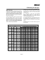
Calibrating the Sprayer
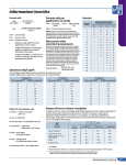
All Silvan booms other than the Fieldmaster boom
are fitted with TP nozzles suitable for a pressure
range from 2.0 to 4.0 Bar. The chart below applies
to these booms.
Nozzle Selection
Refer to the chemical manufacturer’s information
to determine the recommended application rate
in litres per hectare (l/ha) for your particular
situation. Then determine the speed in kilometres
per hour (km/hr) at which you intend to spray,
taking into consideration the ground conditions of
the area to be sprayed.
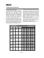
The Fieldmaster is fitted with XR “Extended
Range” nozzles suitable for a wider range of
operating pressures from 1.0 to 4.0 Bar. The chart
on the next page applies to these.
Using the appropriate chart for your boom select
the most suitable nozzle to use at the normal
recommended pressure of 3.0 Bar. The leading
digits in the nozzle number indicate whether it is
an 800 or 1100 fan angle and the last two digits
refer to the size of the opening. Nozzles are
colour coded for easy identification.
For sprayers fitted with a Vineyard boom refer to
the calibrating chart supplied with the boom. If
necessary obtain this information from your Silvan
dealer.
Examples of how to use both charts are given on
the next page.
SPRAY NOZZLE SELECTION CHART - TEEJET TF NOZZLES
F A N T IP
LIQ UID
A P P LIC A T IO N R A T E : LIT R E S P E R H E C T A R E
C O LO UR & F ILT E R P R E S S UR E F LO W R A T E 6
8
10
12
14
16
18
20
22
24
26
28
30
N UM B E R
( B a r)
( L/ M in)
km/ h km/ h km/ h km/ h km/ h km/ h km/ h km/ h km/ h km/ h km/ h km/ h km/ h
GR EEN
T P 8 0 0 15
T P 110 0 15
Y E LLO W
T P 8002
T P 110 0 2
B LUE
T P 8003
T P 110 0 3
R ED
T P 8004
T P 110 0 4
B R O WN
T P 8005
T P 110 0 5
GR EY
T P 8006
T P 110 0 6
WH IT E
T P 8008
T P 110 0 8
10 0
M ESH
80
M ESH
80
M ESH
50
M ESH
50
M ESH
50
M ESH
50
M ESH
2 .0
2 .5
3 .0
3 .5
4 .0
0 .4 9
0 .5 5
0 .6 0
0 .6 5
0 .6 9
98
110
12 0
13 0
13 9
74
82
90
97
10 4
59
66
72
78
83
49
55
60
65
69
42
47
51
56
59
37
41
45
49
52
33
37
40
43
46
29
33
36
39
42
27
30
33
35
38
25
27
30
32
35
23
25
28
30
32
21
23
26
28
30
20
22
24
26
28
2 .0
2 .5
3 .0
3 .5
4 .0
0 .6 5
0 .7 3
0 .8 0
0 .8 6
0 .9 2
13 1
14 6
16 0
17 3
18 5
98
110
12 0
13 0
13 9
78
88
96
10 4
111
65
73
80
86
92
56
63
69
74
79
49
55
60
65
69
44
49
53
58
62
39
44
48
52
55
36
40
44
47
50
33
37
40
43
46
30
34
37
40
43
28
31
34
37
40
26
29
32
35
37
2 .0
2 .5
3 .0
3 .5
4 .0
0 .9 8
1.10
1.2 0
1.3 0
1.3 9
19 6
2 19
240
259
277
14 7
16 4
18 0
19 4
208
118
13 1
14 4
15 6
16 6
98
110
12 0
13 0
13 9
84
94
10 3
111
119
74
82
90
97
10 4
65
73
80
86
92
59
66
72
78
83
53
60
65
71
76
49
55
60
65
69
45
51
55
60
64
42
47
51
56
59
39
44
48
52
55
2 .0
2 .5
3 .0
3 .5
4 .0
1.3 1
1.4 6
1.6 0
1.7 3
1.8 5
2 6 1 19 6
2 9 2 2 19
320 240
346 259
369 277
15 7
17 5
19 2
207
222
13 1
14 6
16 0
17 3
18 5
112
12 5
13 7
14 8
15 8
98
110
12 0
13 0
13 9
87
97
10 7
115
12 3
78
88
96
10 4
111
71
80
87
94
10 1
65
73
80
86
92
60
67
74
80
85
56
63
69
74
79
52
58
64
69
74
2 .0
2 .5
3 .0
3 .5
4 .0
1.6 3
1.8 2
2 .0 0
2 .16
2 .3 1
326
364
400
432
462
245
273
300
324
346
19 6
2 18
240
259
277
16 3
18 2
200
2 16
231
14 0
15 6
17 1
18 5
19 8
12 2
13 7
15 0
16 2
17 3
10 9
12 1
13 3
14 4
15 4
98
10 9
12 0
13 0
13 9
89
99
10 9
118
12 6
82
91
10 0
10 8
115
75
84
92
10 0
10 7
70
78
86
93
99
65
73
80
86
92
2 .0
2 .5
3 .0
3 .5
4 .0
1.9 6
2 .19
2 .4 0
2 .5 9
2 .7 7
392
438
480
5 18
554
294
329
360
389
4 16
235
263
288
3 11
333
19 6
2 19
240
259
277
16 8
18 8
206
222
238
14 7
16 4
18 0
19 4
208
13 1
14 6
16 0
17 3
18 5
118
13 1
14 4
15 6
16 6
10 7
12 0
13 1
14 1
15 1
98
110
12 0
13 0
13 9
90
10 1
111
12 0
12 8
84
94
10 3
111
119
78
88
96
10 4
111
2 .0
2 .5
3 .0
3 .5
4 .0
2 .6 1
2 .9 2
3 .2 0
3 .4 6
3 .7 0
522
584
640
692
740
392
438
480
5 19
555
3 13
350
384
4 15
444
261
292
320
346
370
224
250
274
297
3 17
19 6
2 19
240
260
278
17 4 15 7
19 5 17 5
2 13 19 2
231 208
247 222
14 2
15 9
17 5
18 9
202
13 1
14 6
16 0
17 3
18 5
12 0
13 5
14 8
16 0
17 1
112
12 5
13 7
14 8
15 9
10 4
117
12 8
13 8
14 8
Page 15
Calibrating the Sprayer
Alternatively, the same rate of 100 l/ha could also
be achieved with a larger nozzle and faster
operating speed. By referring to the Teejet TP
nozzle chart on the previous page it can be seen
that an TP8003 or TP11003 blue nozzle will give
this rate at a little under 14 km/hr and 3.0 Bar (the
rate shown on the chart at 14 km/hr is 103 l/ha ).
Similarly an XR8003 or XR11003 blue nozzle will
also give 100 l/ha at a little under 14 km/hr and
pressure of 3.0 Bar (the rate shown on the chart
below at 14 km/hr is 101 l/ha.)
It can thus be seen that a variety of choices exist
for most application rates and the final selection of
nozzle, speed and pressure will depend upon the
factors which best suit your conditions.
Always perform a calibration check to confirm your
nozzle selection, as described on page 14.
Using The Calibration Charts
For example, a rate of 96 l/ha can be achieved at
a ground speed of 10 km/hr using 3.0 Bar
pressure with either an TP8002 or TP11002
yellow nozzle - refer to the Teejet TP nozzle
selection chart on the previous page. An almost
identical rate of 95 l/ha can be achieved at the
same speed and pressure with an XR8002 or
XR11002 yellow nozzle - refer to the nozzle
chart below. Of course the spray boom will have
to be set to a different height depending on
whether an 800 or 1100 nozzle is chosen.
If the exact application rate does not appear in
the chart it can be achieved by slightly adjusting
the speed or pressure. For example, if a rate of
100 l/ha is required rather than 96 l/ha (or 95
l/ha), it can be achieved with the same yellow
nozzles by reducing the speed to 9.5 km/hr or
increasing pressure to approximately 3.2 Bar.
SPRAY NOZZLE SELECTION CHART
F A N T IP
LIQ UID
A P P LIC A T IO N R A T E : LIT R E S P E R H E C T A R E
C O LO UR & F ILT E R P R E S S UR E C A P A C IT Y
6
8
10
12
14
16
18
20
22
24
N UM B E R
( B a r)
( L/ M in)
km/ h km/ h km/ h km/ h km/ h km/ h km/ h km/ h km/ h km/ h
OR A N GE
XR 8001
X R 110 0 1
GR EEN
X R 8 0 0 15
X R 110 0 15
Y E LLO W
XR 8002
X R 110 0 2
B LUE
XR 8003
X R 110 0 3
R ED
XR 8004
X R 110 0 4
B R O WN
XR 8005
X R 110 0 5
GR EY
XR 8006
X R 110 0 6
10 0
M ESH
10 0
M ESH
50
M ESH
50
M ESH
50
M ESH
50
M ESH
50
M ESH
1.0
1.5
2 .0
3 .0
4 .0
0 .2 3
0 .2 8
0 .3 2
0 .3 9
0 .4 6
46
56
64
78
92
35
42
48
59
69
28
34
38
47
55
23
28
32
39
46
20
24
27
33
39
17
21
24
29
35
15
19
21
26
31
14
17
19
23
28
13
15
17
21
25
12
14
16
20
23
1.0
1.5
2 .0
3 .0
4 .0
0 .3 4
0 .4 2
0 .4 8
0 .5 9
0 .6 8
68
84
96
118
13 6
51
63
72
89
10 2
41
50
58
71
82
34
42
48
59
68
29
36
41
51
58
26
32
36
44
51
23
28
32
39
45
20
25
29
35
41
19
23
26
32
37
17
21
24
30
34
1.0
1.5
2 .0
3 .0
4 .0
0 .4 6
0 .5 6
0 .6 4
0 .7 9
0 .9 1
92
112
12 8
15 8
18 2
69
84
96
119
13 7
55
67
77
95
10 9
46
56
64
79
91
39
48
55
68
78
35
42
48
59
68
31
37
43
53
61
28
34
38
47
55
25
31
35
43
50
23
28
32
40
46
1.0
1.5
2 .0
3 .0
4 .0
0 .6 8
0 .8 4
0 .9 7
1.18
1.3 7
13 6 10 2
16 8 12 6
19 4 14 6
2 3 6 17 7
274 206
82
10 1
116
14 2
16 4
68
84
97
118
13 7
58
72
83
10 1
117
51
63
73
89
10 3
45
56
65
79
91
41
50
58
71
82
37
46
53
64
75
34
42
49
59
69
1.0
1.5
2 .0
3 .0
4 .0
0 .9 1
1.12
1.2 9
1.5 8
1.8 2
18 2 13 7
2 2 4 16 8
2 5 8 19 4
3 16 2 3 7
364 273
10 9
13 4
15 5
19 0
2 18
91
112
12 9
15 8
18 2
78
96
111
13 5
15 6
68
84
97
119
13 7
61
75
86
10 5
12 1
55
67
77
95
10 9
50
61
70
86
99
46
56
65
79
91
1.0
1.5
2 .0
3 .0
4 .0
1.14
1.4 0
1.6 1
1.9 7
2 .2 8
2 2 8 17 1 13 7 114
2 8 0 2 10 16 8 14 0
3 2 2 2 4 2 19 3 16 1
3 9 4 2 9 6 2 3 6 19 7
456 342 274 228
98
12 0
13 8
16 9
19 5
86
10 5
12 1
14 8
17 1
76
93
10 7
13 1
15 2
68
84
97
118
13 7
62
76
88
10 7
12 4
57
70
81
99
114
1.0
1.5
2 .0
3 .0
4 .0
1.3 7
1.6 7
1.9 3
2 .3 7
2 .7 4
274 206
334 251
386 290
474 356
5 4 8 4 11
16 4 13 7 117 10 3
2 0 0 16 7 14 3 12 5
2 3 2 19 3 16 5 14 5
2 8 4 2 3 7 2 0 3 17 8
329 274 235 206
91
111
12 9
15 8
18 3
82
10 0
116
14 2
16 4
75
91
10 5
12 9
14 9
69
84
97
119
13 7
Page 16
Optional Equipment
Tighten the two clamping screws firmly.
Foam Markers
All Silvan linkage sprayers can be fitted with 14L or
30L Foam markers. Refer to the Foam Marker
Operator’s Manual for installation and operating
procedures relevant to the type of marker fitted to
your sprayer.
Boom End Taps
The end tap is a simple 1/2” BSP connection and
on/off tap with hose elbow which can be screwed
into the end of the boom sprayline to allow direct
flushing of any chemical residues after spraying is
finished. Before resuming spraying ensure that the
tap is closed to avoid loss of chemicals.
BOOM HEIGHT SKIMMER
Dual Stage Pressure Gauge
The dual stage gauge features an expanded
scale of dial markings at the low pressure end to
enable accurate setting of both high and low
operating pressures. It is standard equipment on
Prolink and Paddockmaster sprayers and is
available as an option for all other models.
BOOM END TAP
Boom Fence Line Kit
The fence line kit includes a 1/2” BSP connect- ion,
on/off tap and adjustable swivel nozzle holder
which can be screwed into the end of the boom
spray line to direct chemical to the base of a fence
without the risk of the boom contacting. It can be
fitted in conjunction with an end tap.
DUAL STAGE PRESSURE GAUGE
Cabin Mounted Boom On/Off Control
BOOM FENCE LINE KIT
Boom Height Skimmer
Skimmers can be easily fitted to any Silvan boom
to help maintain a uniform spraying height over
uneven terrain and are normally fitted in pairs at
the same location on each side of the boom.
Drill the outer arm section of the boom at the
required location and attach the mounting bracket
with two bolts. Install the skimmer in the bracket
and adjust so that it is in light contact
with the ground at the required spraying height.
Page 17
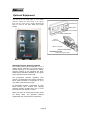
This cabin control can be used with 3 section
spray booms to enable spraying to be stopped
and started from the tractor seat by operation of
electric solenoid valves. Each boom section can
be selected individually by operating one of the
“on/off” switches. When this option is ordered the
solenoid valves are factory fitted.
Install the control unit in a convenient location in
the tractor cabin using the hardware provided.
Connect the electrical cable provided directly to
the battery. The connections are:
Positive = Red or Brown
Negative = Black or Blue
If the cable needs to be extended it is important
to use wire of the same diameter.
Run the control loom to the sprayer through a
convenient outlet in the tractor cabin ensuring it
Optional Equipment
does not rub on any sharp edges, or use a rubber
grommet. Connect the tractor loom to the sprayer
loom with the quick release coupling. Ensure the
loom is clear of the PTO shaft and tractor
wheels.
Boom Switches
Master Switch
Pressure Switch
Cabin Control Unit
Pressure
Compensators
Maximum Pressure
Solenoid Valve Block
SILVAMATIC ELECTRIC SPRAYING CONTROLS
Three section system shown.
Silvamatic Electric Spraying Controls
This control system can be used with 2, 3 or 5
section booms, depending on Control model. It
enables spraying to be stopped and started,
spraying pressure to be regulated and boom
sections to be selected individually or as a group
by the operator from the tractor seat.
The proportional pressure regulating valve
ensures the application rate remains constant if
travel speed increases or decreases by up to
15% whilst in the same tractor gear.
An adjuistable pressure compensator on each
boom section valve ensures that spraying
pressure remains constant when one or more
boom sections are opened or closed.
When this option is ordered the solenoid valves
are factory fitted. The Operator’s Manual
supplied with the unit provides full instructions.
Page 18
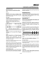
Lubrication and Maintenance
Daily Maintenance
Before carrying out any maintenance, please
switch off the tractor and disconnect the drive
shaft.
Never leave chemicals in the tank that may settle to
the bottom, harden and break into lumps as this may
block the suction filter.
Weekly Maintenance
General
During the first few days of operation, before
starting each day check that all hardware is tight
and inspect the unit for leaks while running and
tighten all hose clamps.
PTO Shaft (Every 20 Hrs)
Slide the PTO shaft apart, clean the telescopic tubes
with kerosene and apply multi-purpose grease to the
sliding surfaces, then reassemble. This is most
important in dusty conditions.
PTO Shaft
Grease the PTO shaft with multi-purpose grease
at the time intervals shown below. This is the
amount of lubrication recommended for normal
operation. More frequent inspection and
lubrication may be needed under very dusty
conditions.
Annual Maintenance
PTO SHAFT LUBRICATION POINTS
Pump
Check the oil level in the viewer daily and if
necessary top up with SAE 20-40 multigrade
engine oil.
Diaphragm Pump
Drain the oil from the diaphragm pump annually, or at
the end of each spraying season, and refill with SAE
20-40 multi-grade engine oil.
Remove the pump heads, carefully inspect the
diaphragms and replace if necessary. Also check the
inlet and outlet valves, seats and springs for wear,
damage or chemical corrosion and replace as
necessary.
Check the air pressure in the surge chamber at the
end of the pump which smooths out the pulsations in
fluid flow. The air pressure behind the chamber’s
diaphragm should be set in accordance with the
spraying pressure being used, as shown in the chart
below.
SPRAYING PRESSURE (Bar)
SURGE AIR PRESSURE (Bar)
2-5
2
5-10
10 -20
2-5
5-7
Filters
Clean all filters daily or as stated below. More
frequent cleaning may be found necessary
depending upon circumstances. The best
method for cleaning filters is to wash them with a
soft bristle brush. Check for any tears or holes
and replace if damaged.
Adjust the pressure at the valve fitting on the
chamber using using a compressed air hose fitted
with a tire valve connection and a reliable pressure
gauge.
Check and if necessary clean the basket strainer
under the tank lid before each fill.
Electrical Fuses
Always clean the suction filter before each tank
refill and at the end of the day. Close the stop
valve by pushing the cap in and turning it in the
direction indicated on the cap out, then unscrew
the filter cover to remove the filter element - refer
diagram in Operation section. Ensure the ‘O’ ring
is in good condition when refitting.
Tank and Spray Lines
At the end of each day run clean water through
the pump and lines to purge them of chemicals.
Rinse out the tank to remove powdered material.
Refer to the pump instruction manual for further
details on the above maintenance operations.
The cabin control units used with boom solenoid
valves and foam markers include a fuse to protect
their electrical circuits.
If the electrical system fails to operate remove the
fuse and check whether it has blown. If so, first locate
and rectify the fault, then replace the fuse with one of
the correct 8 amp rating. A blown fuse may indicate
that an electrical lead has rubbed through on a sharp
surface.
Hardware
At the end of each season generally inspect the
sprayer for any signs of damage and check that all
bolts are securely tightened.
Page 19
SILVAN AUSTRALIA PTY. LTD.
ABN 48 099 851 144
89 Lewis Rd
Wantirna South 3152
Australia
Telephone: +61 (03) 9887 2788
Facsimile: +61 (03) 9887 1035
www.silvanaust.com
SILVAN NEW ZEALAND PTY.LTD.
22Sunshine Ave
Te Rapa, Hamilton 2001
New Zealand
Telephone: +64 (07) 849 6030
Facsimile: +64 (07) 849 6070
www.silvannz.co.nz
Page 19