1
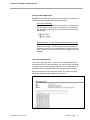
CHLORIDE POWER PROTECTION User Guide ManageUPS® CIO ALARM MONITORING ASSET MANAGEMENT FOR REMOTE SITE & DISTRIBUTED UPS INSTALLATIONS Version: 1.0 Licenses and Trademarks ManageUPS and MopUPS are registered trademarks of ONEAC Corporation, A Chloride Power Protection Company. All other trademarks, product and corporate names are the property of their respective owners. Entire contents copyright ©2006 ONEAC Corporation. All rights reserved. Reproduction in whole or in part without permission is prohibited. Controlled Document Number 913-601 Rev - 28 June 2006 BEFORE YOU BEGIN ManageUPS CIO . . . version 1.0 This software will monitor UPS from CHLORIDE companies that are represented on a TCPIP network by ManageUPS NET ADAPTERS MopUPS software This software will also monitor UPS from 3rd parties that are represented on a TCPIP network by an SNMP agent that is compliant with the RFC1628 UPS MIB. Please review System Requirements in Section 1 before installing ManageUPS CIO. i TABLE OF CONTENTS SECTION I: OVERVIEW OVERVIEW............................................................................................................................1 Who can use ManageUPS CIO? ...........................................................................................................1 What is ManageUPS CIO? .....................................................................................................................1 System Requirements ...........................................................................................................................2 Hardware Host for ManageUPS CIO Monitoring Service .................................... 2 Host OS for ManageUPS CIO Monitoring Service .............................................. 2 Host OS for ManageUPS CIO GUI ...................................................................... 2 Network Infrastructure and Security..................................................................... 3 UPS Network Management Agents ..................................................................... 3 System Elements: Device, Agent and Manager..................................................................................4 Embedded Agents and Proxy Agents .................................................................. 4 Agent Level .......................................................................................................... 5 Terminology Bases ................................................................................................................................6 SECTION 2: INSTALLATION AND QUICK START INSTALLATION MS WINDOWS ...............................................................................................................1 LINUX ..........................................................................................................................2 INSTALLATION NOTES – WINDOWS OR LINUX .................................................................2 REMOTE GUI INSTALLATION............................................................................ 2 SECURE CIO SERVER FOR REMOTE ACCESS.............................................. 2 ii ManageUPS CIO User Guide TABLE OF CONTENTS QUICK START: USING CIO ......................................................................................................... 3 Starting the CIO GUI - Linux ..............................................................................................3 Starting the CIO GUI - Windows........................................................................................3 Adding Devices to the “All Devices” inventory.................................................................................. 5 Local Network .............................................................................................................6 IP Search ...................................................................................................................7 ManageUPSNet (Manual Entry) – MOPNET .....................................................................8 SNMP ........................................................................................................................8 Navigate to Device Level View ............................................................................................................. 9 Setting up your Pin Map...................................................................................................................... 10 Removing default sub-maps ..................................................................................10 Changing a Background Map Image .....................................................................11 Placing devices on the Pin Maps ...........................................................................12 Alarm Indication on Pin Maps ................................................................................13 Tour the Alarm View ............................................................................................................................ 13 Tour the Alarm View ............................................................................................................................ 14 Using Smart Groups ............................................................................................................................ 16 Change of State Notification: .................................................................................17 Alarm Storm Management .....................................................................................17 Default SmartGroups .............................................................................................18 About Bookmarks, Folders and Groups............................................................................................19 Bookmarks .............................................................................................................19 Folders ...................................................................................................................20 Groups....................................................................................................................20 CIO Service Security Settings ............................................................................................................ 21 CIO Mail Settings ................................................................................................................................. 22 CIO License Manager .......................................................................................................................... 23 CONTROLLING THE CIO MONITORING SERVICE .......................................................... 24 MS Windows......................................................................................................................................... 24 Linux...................................................................................................................................................... 24 APPENDICES ManageUPS CIO User Guide iii SECTION I : OVERVIEW AND SCOPE OVERVIEW WHO CAN USE MANAGEUPS CIO? ManageUPS CIO is a tool for Facilities Managers and Power Specialists who oversee UPS and related power systems that support businesscritical loads. CIO is also a tool for IT Infrastructure Specialists and ICT Service Desk personnel responsible for incident control, alert response action lists or asset management. WHAT IS MANAGEUPS CIO? ManageUPS® CIO is software for the Management Workstation element in a system for managing UPS and related critical infrastructure in large facilities, campus or enterprise network environments. In general terms, CIO version 1.0 will provide tools for: ManageUPS CIO User Guide Alarm Monitoring: A central console for visualizing and investigating incidents and alarm conditions from networkattached UPS. Asset Management: Tools for managing a population of UPS devices as an Asset (Inventory). Including asset aging summary, battery maintenance forecasting, capacity in use audit, asset inventory by power rating or manufacturer, incident /alarm trend analysis, etc. Section I, page 1 Section I: Overview and Scope SYSTEM REQUIREMENTS Hardware Host for ManageUPS CIO Monitoring Service Server-class Intel computer 1GHz CPU 1G RAM Ethernet network adapter Host OS for ManageUPS CIO Monitoring Service Microsoft Windows 2000 Microsoft Windows 2003 Server Linux (Redhat 9, ES & SuSE 9.3 ) Host OS for ManageUPS CIO GUI Any of the above listed OS XP Professional is a suitable OS for remote ManageUPS CIO GUI installations. Windows XP as Host OS for ManageUPS Monitoring CIO Service: Security provisions in XP Service Pack 2 will slow the network search utility. Further, if there is a network failure that affects the ability of CIO to connect to more than 10 IP-address destinations, XP security provisions will halt further network traffic from the host computer. Security provisions added to Windows XP by Service Pack 2 will add significant and noticeable delays to all network traffic from the host computer if there are simultaneous attempts to connect to more than 10 unreachable IP destinations. ManageUPS CIO monitoring service initiates IP connections 6 times per minute with each UPS being monitored. If 10 or more UPS IP addresses become unreachable destinations to CIO due to a network problem, XP SP2 will activate these security provisions. This will cause significant and noticable delays in the host computer's network functions that impact all applications. Windows XP may be an acceptable platform for your installation if; A.) the total number of UPS devices to be monitored by ManageUPS CIO is less than 10, and if; B.) no other programs that initiate network connections (such as viruses, VoIP, or network utilities) are attempting to connect to unreachable network addresses from the XP computer. Section I, page 2 ManageUPS CIO User Guide Section I: Overview and Scope Network Infrastructure and Security CIO monitors UPS Management Agents on TCPIP networks using specific ports. You may need to verify that the default ports below are not blocked by network security policy. SNMP uses port 161 MOPNET uses 5055 Network Search uses port 5055 Open agent URL function uses port 80 If the default ports are not allowed – you will need to know which ports are allowed for this use – and you will need to configure your UPS Agents to use the assigned alternate port for MOPNET or SNMP services. UPS Network Management Agents CIO will monitor UPS from CHLORIDE companies that are represented on a TCPIP network by ManageUPS NET ADAPTER (MUN) ManageUPS NET ADAPTER II (MUN-II) MopUPS PROFESSIONAL software, Version 2.x MopUPS PROFESSIONAL P/R EDITION software, Version 3.x CIO will also monitor 3rd party UPS that are represented on a TCPIP network by an SNMP agent that is compliant with the standard UPS MIB (RFC1628) or the Powernet MIB. ManageUPS CIO User Guide Section I, page 3 Section I: Overview and Scope SYSTEM ELEMENTS: DEVICE, AGENT AND MANAGER The diagram below illustrates the main elements of the ManageUPS system. UPS operate at the device layer – objects to be monitored and managed by the system. Devices are represented by Agents. Agents monitor the devices locally and make Device information available on the network. Alarm conditions are detected or interpreted by the Agent and made available to the Manager layer. Embedded Agents and Proxy Agents Embedded Agent Generally, embedded agents are preferred as more dependable. The host environment is a closed system, dedicated to specific device management functions. The agent is hosted in an embedded system – software loaded as firmware in a special purpose computing platform. The ManageUPS NET ADAPTER is a special purpose computing platform designed to host a variety of software services related to UPS management – Data and Event Logging, Network Shutdown Controller, UPS WEB server, FTP server for log download, configuration and firmware update, SNMP agent, Event Message service (email), Telnet Server etc., etc. Section I, page 4 ManageUPS CIO User Guide Section I: Overview and Scope Proxy Agent The Agent is hosted in a general purpose computing platform that may host other applications and services. MopUPS PROFESSIONAL is software designed to monitor a specific UPS primarily for the purpose of calling automated shutdown of the server (MopUPS host) in the event of extended mains failures. In some low power UPS applications, MopUPS may be a cost-effective agent to represent the UPS to ManageUPS CIO. (See Appendix B for more information on configuring MopUPS to serve as a Proxy Agent). However, it should be recognized that when MopUPS calls for shutdown of the server OS, MopUPS monitoring service will no longer be running and the UPS will become invisible to ManageUPS CIO until power is restored and the server is restarted. Agent Level Primary: An Agent communicating directly with a UPS. Secondary: An Agent that retrieves information indirectly, from a UPS status server hosted in a primary Agent. ManageUPS CIO User Guide Section I, page 5 Section I: Overview and Scope TERMINOLOGY BASES If you are already familiar with BMS, BIS or NMS type management systems, you likely have an understanding of the methods, key concepts and specific terminology associated with these systems. While the various management systems referenced use structural elements that are functionally similar across systems, specific terminology may differ. The ManageUPS system and related documentation (including this User Guide) make use of concepts and terminology from internationally accepted sources that provide standardized frameworks for the topic of infrastructure management: ISO/IEC 7498-4 – OSI (Open Systems Interconnection) Basic Reference Model, Part 4, Management framework. ITIL (IT Infrastructure Library) developed and published by the UK OGC (Office of Government Commerce): Service Support (2000) ISBN 0113300158 ICT Infrastructure Management (2002) ISBN 0113308655 IETF Standards 16 (SNMPv1) and 62(SNMPv3) covering the Network Management Framework. ISO 16484-5 /ANSI/ASHRAE 135-2004 & CEN TC 247 -- BACnet – A data communication protocol for Building Automation and Control Networks. Generally, the ISO/IEC 7498 and ITIL references give us concepts and terminology for the activity, focus and “best practice” of ICT systems infrastructure management The IETF/SNMP references give us terminology and concepts for the Agent / Manager elements of the ManageUPS system The ISO 16484 reference helps illustrate the similarities and differences between the more established management framework of the ICT community and the emerging standard management framework of the building automation and control community. Section I, page 6 ManageUPS CIO User Guide Section I: Overview and Scope Acronyms and Vocabulary used in this topic ManageUPS CIO User Guide BMS Building Management Systems BIS Building Information System NMS Network Management System IEC International Electro-technical Commission ISO International Organization for Standardization OSI Open Systems Interconnection OGC Office of Government Commerce (UK) ITIL Information Technology Infrastructure Library ICT The convergence of Information Technology,(IT) Telecommunications and Data Networking Technologies into a single technology (ITIL, ICTIM Glossary) ICTIM Information and Communications Technology Infrastructure Management IETF Internet Engineering Task Force SNMP Simple Network Management Protocol ANSI American National Standards Institute ASHRAE American Society of Heating, Refrigeration and AirConditioning Engineers CEN Committee for European Standardization Section I, page 7 SECTION 2 : INSTALLATION AND QUICK START INSTALLATION – MS WINDOWS ManageUPS CIO is packaged for installation on Windows 2000/2003 Server Edition (preferred for CIO Monitoring Service) and XP Professional (suitable for the CIO GUI on remote workstation). Run the MSI installer from CD or WEB download location: When you reach the Setup Type dialog – select Custom to reach the Custom Setup dialog. Point to each of the program elements in the tree diagram and review the Feature Description entry to familiarize yourself with the various components of the product. Typical installations will install both the GUI and the Monitoring Service on the primary server computer that will host the CIO Monitoring Service. When you only want the CIO GUI installed (for use on remote workstations), block the CIO Monitoring Service elements from being installed as shown above. ManageUPS CIO User Guide Section II, page 1 Section II: Installation and Quick Start INSTALLATION - LINUX ManageUPS-CIO for Linux is packaged as an RPM file. Install ManageUPS-CIO by opening a console with root permissions and enter the following command: $> rpm –ivh /path/to/manageups-cio-install-package.rpm Be sure to enter the proper path, and the proper installation package file name when entering this command. Once the RPM has finished installing the program will be running with a default 2 day, 5 device license key. The section CIO License Manager (Section II Page 23) will show how to install the license key. NOTE: If you are running a local firewall on this computer, you must allow communication on ports 5055 and 161 for ManageUPS CIO to function properly. NOTE: To run ManageUPS CIO as a “GUI Only” install, create (touch) an empty file called “noautostart.” This will disable the daemon’s automatic start on boot up. You can then run the GUI and navigate to ManageUPS-CIO services on running on other servers. $> touch /opt/chloride/etc/noautostart INSTALLATION NOTES – WINDOWS OR LINUX REMOTE GUI INSTALLATION When installing the GUI on a separate workstation computer that will be on a different subnet than the CIO Monitoring Service server, you should note the DNS name or IP address of the CIO server host. You may need this to be able to connect to the CIO Monitoring Server. SECURE CIO SERVER FOR REMOTE ACCESS By default, the GUI uses port 5055 to connect to the Monitoring Service on a remote computer. The Monitoring Service uses port 5055 to monitor mopnet agents and port 161 to monitor SNMP agents. You may need to make sure these ports are open on all routers or firewalls between the CIO GUI, CIO server and the individual UPS agents. You can change the default port settings between CIO Service and GUI using the Service Security dialog available from the main screen: See CIO Service Security Settings (page 21) for more information. Section II, page 2 ManageUPS CIO User Guide Section II: Installation and Quick Start QUICK START: USING CIO STARTING THE CIO GUI - LINUX The ManageUPS-CIO GUI is located at /opt/chloride/bin/cio. You may enter this path in a console prompt, or create a shortcut on your desktop. STARTING THE CIO GUI - WINDOWS The installer will leave a shortcut icon on your desktop to launch the GUI. You can leave this on the Desktop. Or, drag it to the Quick Launch Toolbar located on the Taskbar. Or, delete it and use the Start Menu method; Start >>All Programs >> Chloride Power >> ManageUPS CIO >> ManageUPS CIO GUI When the GUI first starts, the screen will appear as the image below. A “Computer name” should appear in the Navigation Pane. This is the name of the computer on the Local network that is running a copy of the CIO Monitoring Service. Select the entry in the Navigation Pane with the mouse cursor and left click to open the connection between GUI and Service. ManageUPS CIO User Guide Section II, page 3 Section II: Installation and Quick Start When the GUI connects to the CIO Monitoring Service, the Service summary information will be displayed in the Main window, and the Navigation Tree will open under the Computer Name entry in the Navigation Pane. Service Summary Navigation Tree You will use the Navigation Tree to open various windows when you use CIO. is a sort-able list view of all UPS Agents in the management inventory. is a specialized list of devices that are reporting an alert of some type. includes a starter set of country and continent maps. You will want to add your own maps or floor plans or digital photos to help you visualize the location of managed UPS. Any JPG, PNG or GIF image file can be used as a background image in the Pin Map hierarchy. icons represent pre-defined Smart Groups that contain lists of devices meeting specific selection or filter rules. You can change the rules of these Smart Groups – or add your own Smart Groups. Groups, Bookmarks and Folders (not shown) can also be added to the Navigation Tree. These will be explained later. The next step is to add Agent connections to the All Devices inventory. Section II, page 4 ManageUPS CIO User Guide Section II: Installation and Quick Start ADDING DEVICES TO THE “ALL DEVICES” INVENTORY You can access the Add Devices dialog from the button on the main screen. Or, from the Options dialog at the top of the All Devices window. Click the “gear” or … Right-click here to access the pulldown menu. ManageUPS CIO User Guide Section II, page 5 Section II: Installation and Quick Start There are four methods for adding devices to the managed inventory Local Network All ManageUPS II NET ADAPTERS use MDNS technology to publicize their presence on the LAN to any application that is designed to recognize this information. The Add Devices - Local Network option in ManageUPS CIO is designed to recognize this information. This enables automatic listing of any ManageUPS NET II agents on the same LAN (subnet) as the computer hosting the CIO Monitoring Service Devices on the local net that are already in the All Devices inventory are marked with green check mark as shown above. Section II, page 6 ManageUPS CIO User Guide Section II: Installation and Quick Start IP Search Initiates search of a specific subnet range for any ManageUPS NET II, ManageUPS NET I or MopUPS agents. A server computer running MopUPS software may be a Secondary agent or a Primary agent. Agent Level Primary: The Agent is communicating directly with the UPS. Secondary: A proxy Agent has 2nd hand information retrieved from a UPS status server hosted in the primary Agent. (See Section I, page 4 for more information on Agent type and level). You will most likely want to exclude Secondary agents from your UPS inventory as unnecessary and potentially confusing duplicates of the UPS they represent. The search result will show the “Agent Level” of discovered agents so you can easily exclude them from being added to the All Devices inventory. ManageUPS CIO User Guide Section II, page 7 Section II: Installation and Quick Start ManageUPSNet (Manual Entry) – MOPNET Use this option to add MopUPS or ManageUPS net agents using a known IP address or DNS host name. Test Connection This option will be active when an entry is made in the Host entry box. Use this feature to verify that the DNS name or IP address entered manually is active and reachable on the network by ManageUPS CIO SNMP Use this option to add SNMP agents using a known IP address or DNS host name. Select RFC1628 Compliant UPS for Agents that conform to the standard UPS SNMP MIB (RFC1628). Section II, page 8 ManageUPS CIO User Guide Section II: Installation and Quick Start NAVIGATE TO DEVICE LEVEL VIEW Once you have added a device or devices to the All Devices list, you can navigate to the Device Level view by double-clicking the device entry in the list or by right clicking the device entry to access the options menu. In the Device Level view there are three tabs; Status, Alarm History and Agent Information ManageUPS CIO User Guide Section II, page 9 Section II: Installation and Quick Start SETTING UP YOUR PIN MAP Pin Map includes a starter set of country and continent maps. You may prefer to add your own maps, floor plans or digital photos to the map hierarchy to help you visualize the location of managed UPS. Any JPG, PNG or GIF type image file can be used as background image in the Pin Map hierarchy Removing default sub-maps The small map icon on each of the continents in the image above represents a sub-map that exists at a layer below the current view. Rightclick on any unneeded sub-map icon to open a dialog that lets you Remove that sub-map from the Map hierarchy. Section II, page 10 ManageUPS CIO User Guide Section II: Installation and Quick Start Changing a Background Map Image The easiest way to add or change a background image may be to dragand-drop the image file from its folder location onto the map window using the mouse. To browse your computer for image files that may be located in various directories, use the Change Background Image dialog option. To change the background image at any level of the Pin Map – right click any region on the map, or use the Options button (gear symbol) to open the dialog. right click any region on the map The Change Background Image option will open a dialog to browse the file directory to locate the graphic image you want to use. Any JPG, PNG or GIF image file can be used as background image in the Pin Map hierarchy. ManageUPS CIO User Guide Section II, page 11 Section II: Installation and Quick Start The example following uses an image of a facility floor plan. Placing devices on the Pin Maps To add a device to a specific location on a map, right click any list view in the Navigation Tree and choose pen in new window, locate the device in the list, and drag it to the location on the map. The lock icon at the bottom left of the map window will lock the positions of the pins on the map to prevent accidental moves or deletes. Click the lock icon to toggle between lock and unlock state. Section II, page 12 ManageUPS CIO User Guide Section II: Installation and Quick Start Alarm Indication on Pin Maps Sub-map icons will display the color of the most severe alarm condition present on devices that are in that branch of the map hierarchy Pins will display the color code of any alarm condition when an alarm is present on the device it represents on the map. ManageUPS CIO User Guide Section II, page 13 Section II: Installation and Quick Start TOUR THE ALARM VIEW Alarm View is a specialized list of devices that are reporting an alert of some type. In the option dialog for the Alarm View – there is an option to Hide Acknowledged Alarms or Show All Alarms. Acknowledged alarms will no longer be visible if the “Hide” option is selected. The indicator of the corresponding Pin and sub-map icons will also be turned off when Hide Acknowledged Alarms is enabled Right click any device to open the device dialog. Once you are sure that an alarm is handled by the appropriate incident and problem management procedures, you can acknowledge the alarm in CIO using the Acknowledge option. Select Open in New Window or double click any device line entry in the list view to open the CIO Device Detail screen. Section II, page 14 ManageUPS CIO User Guide Section II: Installation and Quick Start Navigate to the Alarm Details tab to view Current and Recent Alarm activity for this device. Alarm Statistics show the alarm count and duration statistics that have been recorded by ManageUPS CIO since the device was added to the managed inventory. The statistics counters can be reset from this view. To view longer term event or alarm history that may be stored at the Agent level, use the Open URL option to navigate to the Agent WEB server If the Open URL item is grayed out, select Settings and set the URL. Return to the dialog and select Open URL. ManageUPS CIO User Guide Section II, page 15 Section II: Installation and Quick Start USING SMART GROUPS Smart Groups contain lists of devices with properties from the All Devices inventory that meet specific conditions or rules. (See comment box on page 18: WHEN WILL SMARTGROUP CONTENTS CHANGE? A WORD ABOUT PROPERTIES) Select a Smart Group from the Navigation Tree and right-click in the list area, or use the options button to open the Group Settings dialog. Click the “gear” to open Group Settings You can change the rules of any default Smart Group – or add your own Smart Groups Show Columns dialog defines which columns will be displayed in the List View for that Smart Group. Section II, page 16 ManageUPS CIO User Guide Section II: Installation and Quick Start Change of State Notification: MnageUPS CIO offers two ways to let you know when the contents of a SmartGroup have changed, On Screen and via Email. On Screen Notification When the contents of a Smart Group changes, the Smart Group icon will display a small “open me” triangle to let you know that the contents have changed since the last time the Smart Group was opened. Email Notification - Send Email when Group Contents Change: You can set CIO to send an email whenever the contents of a Smart-Group change. Use the Recipients dialog to define the destination of the email. Use Mail Settings to verify that CIO can route email thru your network mail server. (See page 22 for Mail Settings) Alarm Storm Management In the event of an alarm storm – (such as a wide spread mains failure that causes all UPS to switch to battery, or a network failure that breaks monitoring communications paths), CIO waits for the change activity to settle down before sending a single email summarizing the changes Below is an example of an email summarizing the results of a mains failure that affected 32 UPS at about the same time. ManageUPS CIO User Guide Section II, page 17 Section II: Installation and Quick Start WHEN WILL SMARTGROUP CONTENTS CHANGE? A WORD ABOUT PROPERTIES SmartGroups are very potent mechanisms that can be used to accomplish a variety of tasks. SmartGroup rules remain active even when the SmartGroup window is closed. In other words, the SmartGroup continues to watch the All Devices inventory for devices with properties that satisfy the rules established in the SmartGroup Settings dialog.. It is likely clear that the content of a SmartGroup will change if the rules establish thresholds for properties that you expect to change – such as input volts, %load, battery age, or specific alarm conditions. It might be less obvious that the content of a SmartGroup could change if the watched properties are things that normally do not change…such as UPS manufacturer – or UPS power rating. When new devices are added to the All Devices list and have properties that meet the conditions of a SmartGroup, the contents of that SmartGroup will change to include the new devices. For example, a default SmartGroup watches for devices that do not have a Pin Map association. If the entire existing inventory has been assigned a PinMap location, new devices will automatically appear in the “No Map Location” SmartGroup until you place them on an appropriate map. Default SmartGroups A number of pre-defined SmartGroups are created for you when you install ManageUPS CIO. Some partition the All Devices inventory based on the power rating of the UPS. Others watch for replace battery indications, under-used capacity, devices not yet located on a map, devices off the network or Severe alarms. You can delete the default SmartGroups, modify the rules or add more SmartGroups. If you end up with a long list of SmartGroups that begin to clutter the navigation pane, use the Folders feature to contain Groups that you use to create monthly reports or inventory analyses that you don’t need to Section II, page 18 ManageUPS CIO User Guide Section II: Installation and Quick Start see on a daily basis.. ABOUT BOOKMARKS, FOLDERS AND GROUPS Bookmarks Bookmarks are useful when the CIO GUI and CIO Monitoring Service are installed on different computers that are on different networks. CIO Services on remote subnets will not be visible to the GUI automatically. Setting a Bookmark to the IP address or computer name will let the CIO GUI navigate to the remote CIO Service. If there is a network failure, the CIO Service will not be able to request or receive information from the monitored Agents and the CIO GUI will not be able to connect to the CIO Service. Setting a bookmark for the CIO Monitoring Service on the localhost (same computer as the GUI) will allow the GUI to connect to the Service even if there is a network failure. ManageUPS CIO User Guide Section II, page 19 Section II: Installation and Quick Start Folders Folders are containers for collecting Groups or Smart Groups to reduce clutter on the Navigation Tree. Drag-and-drop items into Folders. Groups Place devices into your Group by dragging them from another list view opened in a separate window (such as All Devices or a Smart Group). Groups are useful for setting up specific list views that display specific sets of information for reporting, export or analysis. For example, you may want to create a report of all devices in the monitored inventory and show specific asset identify information such as manufacturer, model, serial number, etc. Use the Group Settings dialog to select the columns you want to display. The Group Settings above result in the List View below. Section II, page 20 ManageUPS CIO User Guide Section II: Installation and Quick Start CIO SERVICE SECURITY SETTINGS The CIO Service can be accessed from any workstation on your network running the CIO GUI application. To control access to the Service use the Security Settings dialog to set password, port or IP filtering options ManageUPS CIO User Guide Section II, page 21 Section II: Installation and Quick Start CIO MAIL SETTINGS Configure the address or DNS name of the SMTP server that CIO should use to forward email Use the Test feature to verify the settings. If CIO can reach the server, but the mail server refuses the message, CIO will display the error message it receives from the mail server. If CIO cannot reach the mail server, it will display the test result shown. A successful message will return Section II, page 22 ManageUPS CIO User Guide Section II: Installation and Quick Start CIO LICENSE MANAGER Current License information is presented on the main screen. Use the License Manager Dialog if you did not enter a License Key during installation, or need to add an additional key. License Manager will translate and display the attributes of the key A temporary or evaluation key will show the expiration date of the key. ManageUPS CIO User Guide Section II, page 23 Section II: Installation and Quick Start CONTROLLING THE CIO MONITORING SERVICE MS WINDOWS The CIO Monitoring Service installs and registers as a “service” under MS Windows. The ManageUPS CIO Service is configured to start automatically by the installer. Windows Services are controlled through the Services module in the Microsoft Management Console. To restart the Service, or to stop the Service, use the Windows Service Control Manager. LINUX You may use a graphical daemon manager if you choose. Otherwise, the console command options for starting, stopping and restarting the CIO service are : $> /opt/chloride/bin/ciod start $> /opt/chloride/bin/ciod stop $> /opt/chloride/bin/ciod restart NOTE: To run ManageUPS CIO as a “GUI Only” install, create (touch) an empty file called “noautostart.” This will disable the daemon’s automatic start on boot up. You can then run the GUI and navigate to ManageUPS-CIO services on running on other servers. $> touch /opt/chloride/etc/noautostart Section II, page 24 ManageUPS CIO User Guide APPENDICES APPENDIX A : LIST OF UPS PROPERTIES MONITORED At left is a list of UPS properties that CIO may monitor or display. These properties can be used in SmartGroup rules. (Section II, page 16-18) These properties can also be selected for display in any List View using the Group Settings dialog (Section II, page 20) The properties at left marked with a check mark are universal UPS properties within ManageUPS CIO. Properties with out a check mark may or may not contain entries depending on the type of UPS (manufacturer and model families have different capabilities) – or the type of agent representing the UPS (SNMP vs. CHLD MopUPS or ManageUPS agents) ManageUPS CIO User Guide Appendix A page 1 APPENDIX B : MOPUPS SOFTWARE AS PROXY AGENT MopUPS is CHLORIDE’s software for UPS monitoring and safe unattended shutdown of computer operating systems. To use MopUPS as an Agent for UPS monitoring by ManageUPS CIO, the TCPIP network services need to be enabled in the MopUPS service layer. The IP Search utility in ManageUPS CIO’s Add Devices option (See page 7) will locate servers with MopUPS installed as long as the TCPIP services in MopUPS are enabled and the IP port configured in MopUPS is the default mopnet port 5055. If the default IP port has been changed, you will need to use the Manual Entry option in CIO (see page 8) and enter the specific IP address (or DNS name) of the computer running MopUPS, and the specific port number that matches the port settings in MopUPS MopUPS for UNIX and Linux install with TCPIP services enabled by default. MopUPS for Windows installs with TCPIP services disabled. An overview for enabling tcpip in MopUPS for Windows is included below. For more information on how to configure tcpip settings in MopUPS, see the MopUPS on-screen help or User Guide PDF for the specific edition installed in computers of interest. Enabling tcpip services in MopUPS Professional for Windows The Network Protocols tab displays options for enabling network access to MopUPS on this server. ManageUPS CIO User Guide Appendix B page 1