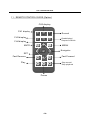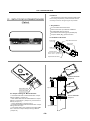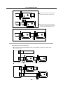
1
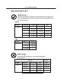
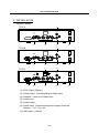
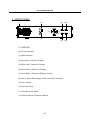
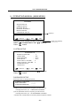
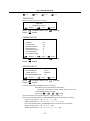
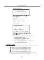
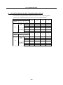
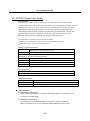
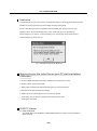
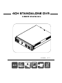
4CH STANDALONE DVR
USER MANUAL
2008 APR.
Ver 1.1
4ch
USB
ALARM
VGA
LAN
Remote
空 白頁
4CH STANDALONE DVR
HDD SUPPORT LIST
Warning:
Should you wish to install a new hard drive in this unit,
a list of tested hard drives shown to be compatible can
be found below.
SATA
Brand
Capacity
Maxtor
160GB
Seagate
HITACHI
WD
-
160GB
-
250GB
250GB
250GB
-
-
320GB
320GB
320GB
-
500GB
500GB
500GB
-
750GB
750GB
-
IDE
Brand
Capacity
Maxtor
Seagate
-
160GB
250GB
250GB
320GB
-
Warning:
The hard drive below is not recommended
for this unit
S A TA
IDE
Brand
Maxtor
HITACHI
Capacity
320GB
1TB
160GB
250GB
500GB
-
250GB
320GB
-
-
750GB
-
-
-
1TB
-
WD
WD
4CH STANDALONE DVR
CONTENT
1、FEATURE
2
2、SPECIFICATIONS
3
3、INSTALLATION
4
4、FRONT PANEL
5
5、OPERATING MANUAL
6
6、VIEW CONTROL
8
7、PLAYBACK CONTROL
9
8、RECORD CONTROL
9
9、4 CHANNEL RECORDING HOURS
10
10、DVR Viewer User Guide
11
11、REMOTE CONTROL GUIDE(Option)
18
12、SATA TO PATA CONVERT BOARD(Option) 19
-1-
4CH STANDALONE DVR
1、FEATURE
1、Definitely Standalone.
2、Real Time Refresh Rate.
3、Display While Recording.
4、Frame Recording & Quad Recording.
5、Compatible of NTSC/PAL format.
6、Advanced MJPEG.
7、Manual / Motion / Programmed
8、 Systems records automatically while alarming.
9、Search by Time / Date.
10、Watch dog feature.
11、HDD Volume Indicator.
12、Can use USB to link PC, Player can search Time to Play、
saving and take photos functions.
13、Internal motion detect feature.
14、Support Audio Recording.
15、Remote Control (Option).
16、Support XGA Output (Option).
17、Support LAN Output (Option).
18、SATA To Pata Convert Board (Option).
-2-
4CH STANDALONE DVR
2、SPECIFICATIONS
ITEM
Video Format
System
VGA OUTPUT
Video Input Channel
Video Output Channel
Audio Input Channel
Audio Output Channel
Display Frame
Recording Frame
Rate (QUAD)
Recording Frame
Rate(EACH)
Recording Mode
Resolution
Compression Format
HDD
Backup Device
Search
Alarm Input
Motion Detect
Video Loss
Auto Switching
Buzzer Output
Brightness Adjust
Contrast Adjust
USB Output
VGA Output
Looping Output
System monitor
LAN Card
Power Input
DESCRIPTION
NTSC/PAL
Embedded RTOS
D-SUB 15Pin VGA
4CH (1Vp-p 75 Ω ) BNC
1CH (Monitor Out) BNC
1CH RCA
1CH RCA
120 fields/s (4x30 fps)
NTSC
100 fields/s (4x25 fps)
PAL
Max. 30 fps
NTSC
Max. 25 fps
PAL
Max. 7.5 fps (30 fps / 4ch)
NTSC
Max. 6.25 fps (25 fps / 4ch)
PAL
Continuous /Motion / Programmed
Display
720x480
NTSC
720x576
PAL
Recording
640x224
NTSC
640x272
PAL
Modified
12K Bytes / Frame
Low
MJPEG
15K Bytes / Frame
Normal
20K Bytes / Frame
High
IDE HDD x 1
USB
Time / Date / Event
Mode
YES
Full
screen
NONE
YES
YES
YES
YES
YES
YES
YES
YES(Option)
NONE
Power recover auto restore record mode
MPEG4(Option)
DC 12V / 4A(AC100V~240V 50/60HZ)
-3-
4CH STANDALONE DVR
3、INSTALLATION
REAR PANEL
(4)
TYPE A
AUDIOIN
DEFAULT
LAN
DC12V
XGA
VIDEOOUT
1
3
2
4
VIDEOIN
(5)
(3)
(2)
(6)
(4)
TYPE B
AUDIOIN
DEFAULT
LAN
DC12V
XGA
(1)
VIDEOOUT
1
3
2
4
VIDEOIN
(2)
TYPE C
(3)
(5)
(7)
(4)
(6)
AUDIOIN
DEFAULT
LAN
DC12V
XGA
(1)
VIDEOOUT
1
3
2
(2)
4
VIDEOIN
(5)
(3)
(6)
(1) XGA Output ( Option )
(2) Video Output : Corresponding to Video Input.
(3) Video IN : Cameras to Video Input.
(4) Audio Input.
(5) Audio Output.
(6) Power Input : Please use the power supply attached
Adaptor : DC-12V / 4A
(7) LAN Output : (Option)
-4-
4CH STANDALONE DVR
4、FRONT PANEL
(1)
( 9 ) (10)
(2)
(4)
(7)
(5)
(6)
(8)
(3)
(11) (12)
(1) USB PORT
(2) Power Indicator
(3) HDD Indicator
(4) Move Up / Camera 1 Display
(5) Move Left / Camera 2 Display
(6) Move Down / Camera 3 Display
(7) Move Right / Camera 4 Display / Select
(8) Menu / Show Percentage of the hard Drive recorded
(9) Play / Pause
(10) Record / Stop
(11) Fast Reverse / Mute
(12) Fast Forward / Sequence Switch
-5-
4CH STANDALONE DVR
5、OPERATING MANUAL (MAIN MENU)
MAIN MENU
SYSTEM SETUP
CAMERA SETUP
RECORD SETUP
RECORD SCHEDULE
MOTION SETUP
HARD DRIVE SETUP
XGA RESOLUTION : 1024 X 768
SYSTEM RESTORE
(
) : SELECT (
) : SET
(
(Option)
) : EXIT
XGA RESOLUTION : 640X480, 800X600, 1024X768 ( default setting) ,1280X1024. (Option)
Press
Press
to select items, use
to exit
to enter.
SYSTEM SETUP
SYSTEM SETUP
BUZZER ALARM TIME
LOSS ALARM
AUDIO RECORD
AUDIO MUTE
AUDIO INPUT VOLUME
AUDIO OUTPUT VOLUME
PASSWORD SETUP
TIME SETUP
(
) : SELECT (
Press
Press
:
2
: ﹝ON﹞
: ﹝OFF﹞
: ﹝OFF﹞
: 8
: 8
) : SET
(
to select items, use
to exit
) : EXIT
to enter.
PASSWORD SETUP
Select this item to change password :
CURRENT PASSWORD
NEW PASSWORD
CONFIRM PASSWORD
:______
:______
:______
(1) When the new password is accepted, you will receive a
message that inform you. PASSWORD CHANGED
(2) If the password was not accepted, you will receive a
message that inform you. NO PASSWORD CHANGED
*Use the view control button on the front panel to input the number.
-6-
4CH STANDALONE DVR
is:"1"
is:"2"
is:"3"
is:"4”
TIME SETUP
Select this item to set up current time.
TIME SET
(
2008/03/16 18:00:30
) : SELECT (
): SET
(
Press
Press
): EXIT
to select items, use
to exit
to enter.
CAMERA SETUP
CAMERA SETUP
CAMERA
LIVE ON/OFF
RECORD ON/OFF
BRIGHT SETUP
CONTRAST SETUP
COLORS SETUP
AUTO SWITCHING
(
) : SELECT
Press
Press
(
: CH1
: ON
: ON
: 5
: 5
: 5
: 2
): SET
(
): EXIT
to select items, use
to exit
to enter.
RECORD SETUP
RECORD SETUP
(
RECORD MODE
:EACH
VIDEO QUALITY
:NORMAL
RECORD FRAME RATE
:30
) : SELECT
Press
Press
(
): SET
(
to select items, use
to exit
): EXIT
to enter.
(1) Record Setup:EACH MODE (frame recording),
Each Mode frame rate alternatives as follows:
Maximum : 7.5 fps each camera Totally :30 fps = 7.5 x 4 CH
QUAD MODE (quad recording).
In this mode
、
、
、
invalid.
(2) Video Quality: video quality selection: High, Normal, Low
(3) Record Frame Rate(NTSC): QUAD MODE frame rate alternatives as follows:
Enable Audio Record → 30、15、10、7、5、4 fps.
Disable Audio Record → 30、15、10、7、5、4、3、2、1 fps.
Record Frame Rate(PAL): QUAD MODE frame rate alternatives as follows:
Enable Audio Record → 25、12、8、6、4 fps.
Disable Audio Record → 25、12、8、6、4 、3、2、1 fps.
-7-
4CH STANDALONE DVR
RECORD SCHEDULE
RECORD SCHEDULE
TTTTTTTTTTTTTTTTTTTTTTTT
:
:
:
:
:
:
:
:
0
3 6 9 12 15 18 21
Press
Press
to select items, use
to exit
to enter.
(1)Range: 0-24 hrs.
(2)Set ”T” for continuous recording.
(3)Set “M” for motion recording.
(4)Set up ”-” to disable the recording.
MOTION SETUP
MOTION SETUP MENU
CHANNEL-1
CHANNEL-2
CHANNEL-3
CHANNEL-4
(
) : SELECT
Press
Press
SENSITIVITY
SENSITIVITY
SENSITIVITY
SENSITIVITY
(
): SET
0
0
3
5
(
(OFF)
(OFF)
.
.
): EXIT
to select items, use
to exit
to enter.
★ If you want to enable Motion Recording, Please finish
the setup procedure a. and b.
a. Set SENSITIVITY in the menu option
“MOTION SETUP MENU"
b. Set “PROGRAMMED RECORD” --- “M” in the menu
option “RECORD SCHEDULE”.
6、VIEW CONTROL
(1)You can use the following view control buttons to monitor the video from the cameras.
Camera #1 (Ch1), return to Quad Mode by press again.
Camera #2 (Ch2),return to Quad Mode by press again.
Camera #3 (Ch3),return to Quad Mode by press again.
Camera #4 (Ch4),return to Quad Mode by press again.
(2)View Control is only valid while the RECORD MODE is in the EACH MODE.
QUAD Display, Enable / Disable theAuto switching function.
-8-
4CH STANDALONE DVR
7、PLAYBACK CONTROL
(1)Press
, and the system will play the latest event which you haven't seen before.
(2)Press
, and the system will enter the PLAYBACK EVENTS SEARCH MODE.
(3)Each period is as four hour.
SEARCH TIME
HARD DRIVE : MASTER
08/03/16 02:47:56 - 08/03/18 02:47:56
01 TIME
02 TIME
03 TIME
Press
Press
Press
2008/03/16 02:47:50
2008/03/17 02:47:50
2008/03/18 02:47:50
Selec t Start Date/
Time to End Date/
Time
to select items, use
to enter.
to exit,
select event / time.
to switch between the TIME SEARCH MODE and the PLAYBACK
EVENTS SEARCH MODE ,
to exit.
Press
(1)EVENTS SEARCH MODE :
Press
choose one period, then press
to play.
(2)TIME SEARCH MODE :
The signal > goes up to the HARD DRIVER: MASTER. Press
to select items. Use
select to change data, Then press
to play.
(3)PLAYBACK :
*Press
X2,
to speed forward. Continue to press
X4,
and show
X8 , playing.
*Press
to rewind the playback.
*Press
to pause.
*Press
to stop.
8、RECORD CONTROL
(1)Press to start recording.
(2) During recording, the mark * appears in status of overwriting
-9-
4CH STANDALONE DVR
9、4CH RECORDING HOURS ON 80GB HARD DRIVE
*Thereinafter a rough estimate a table for reference only, recording data
quantity can follow an image a variation a rate somewhat different.
Re cording Re sults in NT SC Forma t
Video
Signal
30 fps
15 fps
7 fps
1 fps
Display
Format
Video
Quality
Hi gh
36Hours
72 Hours
144 Hours
1,080 Hours
QU AD
MOD E
Nor mal
48 Hours
96 Hours
192 Hours
1,440 Hours
NT SC
EA CH MOD E
(Full Sc reen)
Bas ic
58 Hours
116 Hours
232 Hours
1,740 Hours
Hi gh
64 Hours
128 Hours
256 Hours
1,920 Hours
Nor mal
90 Hours
180 Hours
360 Hours
2,700 Hours
Bas ic
112 Hours
224 Hours
448 Hours
3,360 Hours
Re cording Re sults in PAL Forma t
Video
Signal
Display
Format
QU AD
MOD E
PAL
EA CH MOD E
(Full Sc reen)
Video
Quality
25 fps
12 fps
6 fps
1 fps
Hi gh
38 Ho urs
76 Ho urs
152 Ho urs
950 Ho urs
1,200 Ho urs
Nor mal
48 Ho urs
96 Ho urs
192 Ho urs
Bas ic
60 Ho urs
120 Ho urs
240 Ho urs
1,500 Ho urs
Hi gh
62 Ho urs
124 Ho urs
248 Ho urs
1,550 Ho urs
Nor mal
90 Ho urs
180 Ho urs
360 Ho urs
2,250 Ho urs
Bas ic
118 Ho urs
236 Ho urs
472 Ho urs
2,950 Ho urs
-10-
4CH STANDALONE DVR
10、DVR PC Viewer User Guide
Introduction
This document is the Operation Manual for the 4 CH Stand Alone DVR PCViewer.
The application will show you stream image stored in the Storage Device (HDD, CF card,
USB Memory Stick, etc.), which was previously formatted and recorded by the DVR.
If any DVR-formatted Storage Device is connected to your PC, the application will
automatically detect the Storage Device and show the recorded stream. You can also
save the current screen to a JPEG file, and save the video/audio stream to a file
[MYS file, the Vineyard's proprietary video/audio stream file format.
The application consists of two functional modules:
DVR PC Viewer Shows stream stored in the DVR Storage Device.
MYS File Player Plays captured stream file.
Terms in This Document
Storage Device
Hard Disk, CF Card, USB Memory Stick
The Application
DVR Storage Device PC Viewer
DVR Storage Device Storage Device which was previously formatted and recorded by the
DVR base on Vineyard Technologies' DVR chip.
OS
Operating System
CPU
Central Processing Unit
RAM
Random Access Memory
GUI
Graphic User Interface
Requirement
OS
OS of your PC should be Windows 2000(SP4) / XP(SP2) or later.
DirectX
Your PC should be equipped with DirectX 7.0 or later.
Recommendation
Operating System (OS)
The application runs only on Windows 2000 (SP4) / XP (SP2) or later
CPU
1.0 GHz or Higher.
RAM
256 MByte or greater.
Installation
A. Hardware Installation
Before executing the application, connect the DVR Storage Device to the IDE cable of your
PC directly, or via USB adaptor
B. Software Installation
Run Setup.exe in the CD-ROM and follow the instruction to finish the installation.
[Make sure that the OS of your PC is Windows 2000 SP4/Windows XP SP2 or later.
-11-
4CH STANDALONE DVR
Execution
Just double click the icon of PC Viewer. The application will try to detect physical storage devices
installed at your PC and search for DVR storage device(s) among them.
If there is DVR Storage Device, the application will automatically start playing. However, If the
application fails to detect DVR Storage Device, which means that there is no DVR Storage
Device installed to your system, it will show following error message and set the default working
mode to MYS P layer (See Section. 4).
OK
Fig.1. No DVR Storage Device Message
Shortcut to play the video files on your PC via the attached
USB cable:
a. Connect USB cable both ends to the USB port of the DVR and your PC.
b. Supply 12VDC power to the DVR.
c. Wait until the message of USB detected pops up on the VGA monitor.
d. Run the PC Viewer software accordingly.
e. Wait until the very first image comes up to the PC Viewer.
f. Click “Play” icon on the control panel of the PC Viewer to start
viewing the video files.
DVR PC Viewer
A. User Interface
The default page of the application is DVR Storage Device PC Viewer. The user interface is
shown in Fig.2.
-12-
4CH STANDALONE DVR
(1)
(12)
(11)
(2)
(3)
(4) (5)
(6)
(7)
(8)
(9)
(10)
(1) Screen
(7) PC Viewer Playback Control
(2) Positioning Slider Bar
(8) Capture Stream Button [MYS]
(3) MYS Player Button
(9) Screen Capture Button [JPEG]
(4) DVR Storage Device Change Button
(10) Audio Control
(5) DVR Storage Device Information
(11) Viewer Playback Mode
(6) Channel Selection
(12) Stream Time Display
Fig.2. DVR Storage Device PC Viewer User Interface
B. Functions
i. MYS Player Button
If you want to see MYS file which was stored in your PC, press this button or press [F2] key.
ii. DVR Storage Device Change Button
When there are more than one DVR storage devices, this button will be activated. Press this
button when you want to see video/audio stream stored in other DVR storage device. Fig.3
shows DVR storage device selection window.
Fig.3. DVR Storage Device Selection Window
-13-
4CH STANDALONE DVR
iii. DVR Storage Device Information Button
If you want to know how big is the DVR storage device is, or how much stream data is stored
in the device, press this button. Fig.4 shows the DVR storage device information window.
Fig.4. DVR Storage Device Information Window
iv. Channel Selection Buttons
According to the record channel setting of the stream, each channel buttons will be enabled.
Select any channel you want to see enlarged.
Fig.5. Channel Selection Buttons
Press
button (or [ 5 or Numpad 5 ] Key) to see all 4 channels at the same time.
Press
button (or [ 1 or Numpad 1 ] Key) to see channel 1 enlarged.
Press
button (or [ 2 or Numpad 2 ] Key) to see channel 2 enlarged.
Press
button (or [ 3 or Numpad 3 ] Key) to see channel 3 enlarged
Press
button (or [ 4 or Numpad 4 ] Key) to see channel 4 enlarged.
v. Viewer Control Buttons
Use Viewer Control Buttons to control viewer playback.
Fig.6. Viewer Control Buttons
*Press
button (or [<-] Key) to start fast reverse playback. By pressing this button again,
you can adjust the speed. The maximum speed is 8 times faster than reverse playback.
*Press
button (or [<-] Key) to start reverse playback.
*Press
button (or [Space Bar]) to pause playback.
*Press
button (or [->] Key) to start normal playback.
*Press
button (or [->] Key) to start fast forward playback. By pressing this button several
times, you can adjust the speed. The maximum speed is 8 times faster than normal playback.
-14-
4CH STANDALONE DVR
vi. Capture Stream Button
If you want to capture stream, follow the stream capture procedure listed below:
* Using Positioning Slider Bar find the stream position you want.
* Make sure that the playback is in PAUSE mode, and the Capture Stream Button is enabled.
* Press the button, then the application will start capturing. During capturing, Capturing
Indicator Window will be popped up.
Fig.7. Capturing Indicator Window
* To stop capturing, press Stop Capturing button on the window.
The captured file (an MYS file) will be stored in the Capture Directory. See the Application
Setting Section, to know more about the Capture Directory setting.
vii. Screen Capture Button
If you wan to capture the screen, follow the screen capture procedure listed below:
* Using Positioning Slider Bar find the stream position you want.
* Make sure that the playback is in PAUSE mode, and the Screen Capture Button is enabled.
* Press the button, then the application will start to make a JPEG file. When a JPEG file
successfully created. The application let you know that the image file is created showing
the file name and the Capture Directory path.
viii. Audio Control
Fig.8. Audio Control Buttons
Press
button to enable sound. Once sound is enabled, the button icon will be changed to
. Press it to disable sound again. Using the slider bar, you can adjust the volume.
MYS Player
A. User Interface
Fig. 9 shows the user interface of the MYS player.
-15-
4CH STANDALONE DVR
(1)
(2)
(3)
(10)
(4)
(6)
(5)
(7)
(8)
(9)
(1) Screen
(6) MYS file information
(2) MYS File Select Dialog
(7) MYS File Playback Control
(3) Positioning Slider Bar
(8) Screen Capture Button [JPEG]
(4) PC Viewer Button
(9) Audio Control
(5) File Open Button
(10) Playback Status
Fig.9. MYS File Player User Interface
B. Functions
i. PC Viewer Button
When you want to back to PC Viewer function, press this button.
ii. File Open Button
Press this button to select MYS file.
iii. MYS file information
When an MYS file selected and being played, the file name and the file size will be displayed
in the MYS file information box.
iv. MYS file Playback Control Buttons
Use MYS file playback buttons to control the playback.
Fig.10. MYS file playback control Buttons
-16-
4CH STANDALONE DVR
* Press
button (or [<-] Key) to start fast reverse playback. By pressing this button again,
you can adjust the speed. The maximum speed is 64 times faster than reverse playback.
* Press
button (or [<-] Key) to start reverse playback.
* Press
button (or [Space Bar]) to pause playback.
* Press
button (or [->] Key) to start normal playback.
* Press
button (or [->] Key) to start fast forward playback. By pressing this button several
times, you can adjust the speed. The maximum speed is 64 times faster than normal playback.
v. Screen Capture Button
If you wan to capture the screen, follow the screen capture procedure listed below:
* Using Positioning Slider Bar find the stream position you want.
* Make sure that the playback is in PAUSE mode, and the Screen Capture Button is enabled.
* Press the button, then the application will start to make a JPEG file. When a JPEG file
successfully created. The application let you know that the image file is created showing the
file name and the Capture Directory path.
vi. Audio Control
Fig.11. Audio Control Buttons
Press
button to enable sound. Once sound is enabled, the button icon will be changed to
. Press it to disable sound again. Using the slider bar, you can adjust the volume.
■ Application Setting
A. User Interface
Enable/Disable
Application Closing
Confirm
Change
Captured
File Saving
Directory
Fig.12. Application Setting Dialog
B. Functions
i. Capture Directory
You can specify Capture Directory. To change the path, press Change Button, select
directory you want, and press OK again.
ii. Message Box
You can enable/disable the application close confirm message box.
-17-
4CH STANDALONE DVR
11、REMOTE CONTROL GUIDE (Option)
CH2 display
CH1 display
Record
CH3 display
Quad display/
Sequence Switch
CH4 display
MUTE
MENU
Navigator
SET
Fast Reverse
Fast Forward
Play
Stop record/
Stop playback
Pause
-18-
4CH STANDALONE DVR
Foreword
12、SATA TO PATA CONVERT BOARD
(Option)
This is a SATA convert PATA interface PCB board,
before using the product, please read this manual
carefully for further recognizing for the product!
I. Key Feature
Convert SATA TO PATA interface
Transfer rate max up to 66/100/133MB/sec
No SATA HDD capacity limited
LED indicators for Power(green) & HDD(red)
Compact JBOD ( Big ) special function.
II. Hardware and Install
Power LED
40pin PATA connector
4pin power
connector
HDD LED
Jumper select
Device 0=Master (Jumper off)
Device 1=Slave (Jumper on)
22pin SATA connector
Master SATA HDD
SATA HDD
To Master SATA HDD
Jumper off
4pin power cable
80pin PATA cable
Slave SATA HDD
4pin power cable
III. Jumper setting for Master & Slave
1. One PATA cable with one SATA HDD then Jumper
setting in Master ( Jumper off )
2. One PATA cable with two SATA HDD then Jumper
setting in one is Master ( Jumper off ); and another is
Slave ( Jumper on ).
3. Using JBOD ( Big ) special function.
a.) One PATA cable with two SATA HDD then Jumper
setting same as step 2.
b.) Two PATA cable, each cable with one SATA HDD
then these two Jumpers always setting in Master
( Jumper off )
To Slave SATA HDD
Jumper on
4pin power cable
-19-
4CH STANDALONE DVR
One PATA cable with one SATA HDD,
Jumper set to Master ( Jumper off )
One PATA cable with two SATA HDD,
Jumper one set to Master ( Jumper off
); another set to Slave(Jumper on)
Using JBOD ( Big ) special function
One PATA cable with two SATA HDD, Jumper one set to Master ( Jumper off ); another set to
Slave(Jumper on)
Each one PATA cable with one SATA HDD, Jumper all set to Master ( Jumper off )
-20-
H12C420V03