1
INSTALLATION INSTRUCTIONS
FOR DOWNFLOW SINGLE STAGE GAS FURNACES
(-)801S DOWNFLOW SERIES
(-)801P DOWNFLOW SERIES
(-)(-)80DSS DOWNFLOW SERIES
(-)(-)80DSP DOWNFLOW SERIES
U.L. and/or C.S.A. recognized fuel gas and CO (carbon monoxide) detectors are recommended in all applications, and their installation should be in accordance with the
manufacturer’s recommendations and/or local laws, rules, regulations, or customs.
ISO 9001:2008
Factory Use Only
92-24161-143-02
SUPERSEDES 92-24161-143-01
Contents
TABLE OF CONTENTS
1 TABLE OF CONTENTS. . . . . . . . . . . . . . . . . . . . . . . 2
2 GENERAL INFORMATION . . . . . . . . . . . . . . . . . . . . 3
Receiving . . . . . . . . . . . . . . . . . . . . . . . . . . . . . . . . . . 4
California Proposition 65 Note . . . . . . . . . . . . . . . . . . 4
Checklist . . . . . . . . . . . . . . . . . . . . . . . . . . . . . . . . . . . 5
3 SAFETY INFORMATION. . . . . . . . . . . . . . . . . . . . . . 6
Warnings . . . . . . . . . . . . . . . . . . . . . . . . . . . . . . . . . . . 6
Important Information About Efficiency and Quality. . 7
4 LOCATION REQUIREMENTS . . . . . . . . . . . . . . . . . 8
Site Selection . . . . . . . . . . . . . . . . . . . . . . . . . . . . . . . 8
Clearance – Accessibility . . . . . . . . . . . . . . . . . . . . . . 8
Upflow Dimensions & Clearance Table . . . . . . . . . . . 9
5 DUCTING . . . . . . . . . . . . . . . . . . . . . . . . . . . . . . . . . 10
Downflow Installations . . . . . . . . . . . . . . . . . . . . . . . 10
6 COMBUSTION AND VENTILATION AIR . . . . . . . . 12
Combustion Air Requirements . . . . . . . . . . . . . . . . . 12
Venting . . . . . . . . . . . . . . . . . . . . . . . . . . . . . . . . . . . 16
“B-1” Vertical Venting . . . . . . . . . . . . . . . . . . . . . . . . 16
Special Vent Systems (SVS) . . . . . . . . . . . . . . . . . . 17
Power Vent Systems . . . . . . . . . . . . . . . . . . . . . . . . 18
Existing Vent Systems . . . . . . . . . . . . . . . . . . . . . . . 18
7 GAS SUPPLY. . . . . . . . . . . . . . . . . . . . . . . . . . . . . . 19
Gas Supply and Piping. . . . . . . . . . . . . . . . . . . . . . . 19
Gas Piping . . . . . . . . . . . . . . . . . . . . . . . . . . . . . . . . 20
Gas Pressure . . . . . . . . . . . . . . . . . . . . . . . . . . . . . . 21
Setting Gas Pressure . . . . . . . . . . . . . . . . . . . . . . . . 22
9 ELECTRICAL WIRING . . . . . . . . . . . . . . . . . . . . . . 23
Reversing the Electrical Connection . . . . . . . . . . . . 23
Thermostat . . . . . . . . . . . . . . . . . . . . . . . . . . . . . . . . 24
8 LP CONVERSION . . . . . . . . . . . . . . . . . . . . . . . . . . 25
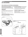
10 ACCESSORIES . . . . . . . . . . . . . . . . . . . . . . . . . . . . 26
Field Installed Option Accessories . . . . . . . . . . . . . . 26
Humidifier . . . . . . . . . . . . . . . . . . . . . . . . . . . . . . . . . 26
4-Inch Flue Adapter . . . . . . . . . . . . . . . . . . . . . . . . . 26
Filters . . . . . . . . . . . . . . . . . . . . . . . . . . . . . . . . . . . . 26
RXGW-B01 Chimney Adapter . . . . . . . . . . . . . . . . . 26
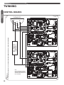
11 TWINNING . . . . . . . . . . . . . . . . . . . . . . . . . . . . . . . . 27
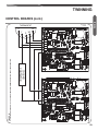
Furnace Twinning Installations . . . . . . . . . . . . . . . . . 27
Control Boards . . . . . . . . . . . . . . . . . . . . . . . . . . 28-29
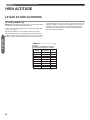
12 HIGH ALTITUDE . . . . . . . . . . . . . . . . . . . . . . . . . . . 30
Natural Gas at High Altitudes . . . . . . . . . . . . . . . . . . 30
LP Gas at High Altitudes. . . . . . . . . . . . . . . . . . . . . . 32
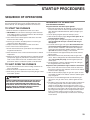
13 STARTUP PROCEDURES . . . . . . . . . . . . . . . . . . . 33
Sequence of Operation . . . . . . . . . . . . . . . . . . . . . . 33
14 DIAGNOSTICS & FAULT CODES . . . . . . . . . . . . . 34
15 LOCKOUT . . . . . . . . . . . . . . . . . . . . . . . . . . . . . . . . 35
16 FIELD SELECTIONS & ADJUSTMENTS . . . . . . . 36
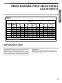
Field Selections – Dipswitches. . . . . . . . . . . . . . . . . 36
17 FAULT CLEAR . . . . . . . . . . . . . . . . . . . . . . . . . . . . . 37
18 FAULT RECALL . . . . . . . . . . . . . . . . . . . . . . . . . . . . 37
19 FLAME STATUS L.E.D. . . . . . . . . . . . . . . . . . . . . . . 37
20 TIMING DIAGRAM. . . . . . . . . . . . . . . . . . . . . . . . . . 37
21 ADJUSTING OR CHECKING FURNACE INPUT . 38
22 SETTING INPUT RATE . . . . . . . . . . . . . . . . . . . . . . 39
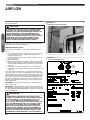
23 AIRFLOW . . . . . . . . . . . . . . . . . . . . . . . . . . . . . . . . . 40
Blower Speed Selection . . . . . . . . . . . . . . . . . . . . . . 41
24 SAFETY FEATURES . . . . . . . . . . . . . . . . . . . . . . . . 42
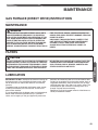
25 MAINTENANCE. . . . . . . . . . . . . . . . . . . . . . . . . . . . 43
Gas Furnace (Direct Drive) Instructions. . . . . . . . . . 43
Filters . . . . . . . . . . . . . . . . . . . . . . . . . . . . . . . . . . . . 43
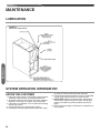
Lubrication . . . . . . . . . . . . . . . . . . . . . . . . . . . . . . . . 43
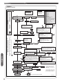
26 SYSTEM OPERATION INFORMATION . . . . . . . . . 44
27 ANNUAL INSPECTION . . . . . . . . . . . . . . . . . . . . . . 45
28 REPLACEMENT PARTS . . . . . . . . . . . . . . . . . . . . . 45
24 DIAGNOSTICS. . . . . . . . . . . . . . . . . . . . . . . . . . . . . 46
30 WIRING DIAGRAM . . . . . . . . . . . . . . . . . . . . . . . . . 47
IMPORTANT: TO INSURE PROPER INSTALLATION AND OPERATION OF THIS PRODUCT, COMPLETELY READ ALL INSTRUCTIONS PRIOR TO ATTEMPTING TO ASSEMBLE, INSTALL, OPERATE, MAINTAIN OR REPAIR THIS PRODUCT. UPON UNPACKING
OF THE FURNACE, INSPECT ALL PARTS FOR DAMAGE PRIOR TO INSTALLATION AND START-UP.
2
GENERAL INFORMATION
The (-)801S/(-)801P series furnaces are design certified by CSA
for use with natural and propane gases as follows:
As a Category I furnace, it may be vented vertically with type B1 vent pipe and also may be common vented as described in
these instructions.
This furnace should be installed in accordance with the American
National Standard Z223.1 - latest edition booklet entitled “National
Fuel Gas Code” (NFPA 54), and the requirements or codes of the
local utility or other authority having jurisdiction including local
plumbing or waste water codes.
With the introduction of higher efficiency furnaces, special attention
must be paid to the venting system. Only listed venting systems
may be used as stated in the installation instructions and the National Fuel Gas Code, ANSI Z223.1 (NFPA 54),. Since furnace
technology and venting requirements are changing, awareness of
local, state, and federal codes and industry changes is imperative.
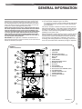
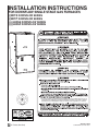
FIGURE 1
15
FURNACE COMPONENTS
16
14
17
18
19
13
1
2
3
12
4
1.
2.
3.
4.
5.
6.
7.
8.
9.
10.
11.
12.
13.
14.
15.
16.
17.
18.
19.
JUNCTION BOX
DOOR SWITCH
CAPACITOR
MAIN PRESSURE SWITCH
INDUCED DRAFT BLOWER (IDB)
MAIN LIMIT
BURNER
FLAME SENSOR
OVER TEMPERATURE SWITCH
IGNITOR GAS VALVE
GAS VALVE
TRANSFORMER
FLUE PIPE ENCLOSURE
HEAT ASSISTED LIMIT CONTROL (HALC)
FLUE CONNECTION
CONTROL MOUNTING PLATE
FURNACE CONTROL
LOW VOLTAGE TERMINAL
BLOWER
5
6
7
11
8
9
10
ST-A1220-13-X0
ST-A1220-13-X0
3
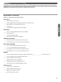
General Information
NOTE: A heat loss calculation should be performed to properly
determine the required furnace BTU size for the structure. Also,
the duct must be properly designed and installed for proper airflow. Existing ductwork must be inspected for proper size and to
make sure that it is properly sealed. Proper airflow is necessary
for both user comfort and equipment performance.
Before opening the furnace carton, verify that the data tags on
the carton specify the furnace model number that was ordered
from the distributor and are correct for the installation. If not,
return the unit without opening the carton. If the model number
is correct, open the carton and verify that the furnace rating
label specifies the same furnace model number that is specified on the carton label. If the model numbers do not match, return the furnace to the distributor.
IMPORTANT: Proper application, installation and maintenance of
this furnace and system is a must if consumers are to receive the full
benefits for which they have paid.
General Information
GENERAL INFORMATION (cont.)
Install this furnace in accordance with the American National Standard Z223.1 – latest edition entitled “National Fuel Gas Code”
(NFPA54) and requirements or codes of the local utilities or other
authorities having jurisdiction. This is available from the following:
National Fire Protection Association, Inc.
Batterymarch Park
Quincy, MA 02269
RECEIVING
Immediately upon receipt, all cartons and contents should be inspected for transit damage. Units with damaged cartons should
be opened immediately. If damage is found, it should be noted on
the delivery papers, and a damage claim filed with the last carrier.
• After unit has been delivered to job site, remove carton taking
care not to damage unit.
• Check the unit rating plate for unit size, electric heat, coil, voltage, phase, etc. to be sure equipment matches what is required for the job specification.
• Read the entire instructions before starting the installation.
• Some building codes require extra cabinet insulation and gasketing when unit is installed in attic applications.
• If installed in an unconditioned space, apply caulking around
the power wires, control wires, refrigerant tubing and condensate line where they enter the cabinet. Seal the power wires on
the inside where they exit conduit opening. Caulking is required to prevent air leakage into and condensate from forming
inside the unit, control box, and on electrical controls.
• Install the unit in such a way as to allow necessary access to
the coil/filter rack and blower/control compartment.
• Install the unit in accordance with any local code which may
apply and the national codes. Latest editions are available
from: “National Fire Protection Association, Inc., Batterymarch
Park, Quincy, MA 02269.” These publications are:
• ANSI/NFPA No. 70-(Latest Edition) National Electrical Code.
• NFPA90A Installation of Air Conditioning and Ventilating Systems.
• NFPA90B Installation of warm air heating and air conditioning
systems.
• The equipment has been evaluated in accordance with the
Code of Federal Regulations, Chapter XX, Part 3280.
4
CALIFORNIA RESIDENTS ONLY
IMPORTANT: All manufacturer products meet current Federal
OSHA Guidelines for safety. California Proposition 65 warnings
are required for certain products, which are not covered by the
OSHA standards.
California's Proposition 65 requires warnings for products sold in
California that contain, or produce, any of over 600 listed chemicals known to the State of California to cause cancer or birth defects such as fiberglass insulation, lead in brass, and combustion
products from natural gas.
All “new equipment” shipped for sale in California will have labels
stating that the product contains and/or produces Proposition 65
chemicals. Although we have not changed our processes, having
the same label on all our products facilitates manufacturing and
shipping. We cannot always know “when, or if” products will be
sold in the California market.
You may receive inquiries from customers about chemicals found
in, or produced by, some of our heating and air-conditioning equipment, or found in natural gas used with some of our products.
Listed below are those chemicals and substances commonly associated with similar equipment in our industry and other manufacturers.
•
•
•
•
Glass Wool (Fiberglass) Insulation
Carbon Monoxide (CO)
Formaldehyde
Benzene
More details are available at the Websites for OSHA (Occupational Safety and Health Administration), at www.osha.gov and the
State of California's OEHHA (Office of Environmental Health Hazard Assessment), at www.oehha.org. Consumer education is important since the chemicals and substances on the list are found
in our daily lives. Most consumers are aware that products present safety and health risks, when improperly used, handled and
maintained.
Installation Instructions remain with the furnace as a reference guide to the servicing contractor. We recommend
that performance and installation data be recorded for future reference on this sheet to meet service and warranty
obligations so that job site information is available when required.
Installation Checklist
REFER TO INSTALLATION INSTRUCTIONS
GAS SUPPLY
______ Correct pipe size (record size)
______ Correct supply pressure (during furnace operation) (record pressure)
______ Manifold pressure (record upstream pressure)
______ No gas leaks
Checklist
______ L.P. Kit Number (if applicable) (record kit number)
ELECTRICAL
______ 115 V.A.C. supply (Dedicated Circuit) (record voltage)
______ Polarity observed
______ Furnace properly grounded
______ Correct wire size (record type and gauge)
FURNACE INSTALLATION
______ Correct clearance to combustibles (record clearance)
______ Correct clearance for service (at front) (record clearance)
DUCT STATIC PRESSURE
______ in. w.c. on heating speed (record static pressure)
______ in. w.c. on cooling speed (record static pressure)
______ Air temperature rise in heat (record air temperature rise)
______ Air temperature rise in cool (record air temperature rise)
VENTING
______ Correct vent pipe diameter and length (according to NFGC tables) _________________ Vent connection size
______ Correct venting material (according to NFGC tables)
______ Correct lining for masonry chimneys
______ Adequate clearance from combustibles
______ Proper negative pressure reading in the vent
______ Vent pipe secured to induced draft blower housing
COMBUSTION AIR
______ Proper source of combustion air
______ Correct combustion air opening size
______ Optional attic combustion air pull
______ Non-attic combustion air pull
5
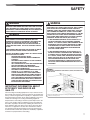
SAFETY INFORMATION
! WARNING
DO NOT INSTALL THIS FURNACE IN A MOBILE HOME!!
THIS FURNACE IS NOT APPROVED FOR INSTALLATION
IN A MOBILE HOME. DOING SO COULD CAUSE FIRE,
PROPERTY DAMAGE, PERSONAL INJURY OR DEATH.
! WARNING
INSTALL THIS FURNACE ONLY IN A LOCATION AND POSITION AS SPECIFIED IN THE LOCATION REQUIREMENTS AND CONSIDERATIONS SECTION OF THESE
INSTRUCTIONS.
! WARNING
IMPROPER INSTALLATION CAN RESULT IN UNSATISFACTORY OPERATION AND/OR DANGEROUS CONDITIONS
AND ARE NOT COVERED BY THE MANUFACTURER’S
WARRANTY.
Safety Information
! WARNING
DO NOT BYPASS, JUMPER, OR REMOVE ANY SAFETY
SWITCH FROM THE FURNACE CONTROL CIRCUIT. IF A
SAFETY SWITCH CAUSES THE FURNACE TO SHUT
DOWN OR OPERATE INTERMITTENTLY, IT IS AN INDICATION OF A POTENTIAL SAFETY HAZARD THAT MUST BE
ADDRESSED BY A QUALIFIED TECHNICIAN, SERVICE
AGENCY OR THE GAS SUPPLIER. DO NOT RESET
SAFETY CONTROLS WITHOUT CORRECTIVE ACTION
AND/OR VERIFICATION OF PROPER SAFE OPERATION
BY A QUALIFIED INSTALLER, SERVICE AGENCY OR THE
GAS SUPPLIER.
REPLACE ANY SAFETY CONTROL COMPONENT ONLY
WITH IDENTICAL OEM REPLACEMENT PARTS. WHEN A
NEW SAFETY SWITCH IS INSTALLED, IT MUST BE
TESTED FOR A MINIMUM OF 15 MINUTES WITH THE
FURNACE OPERATING AT MAXIMUM INPUT RATE AND
WITH BOTH BLOWER AND BURNER DOOR INSTALLED.
IF THE FURNACE IS INSTALLED IN A CLOSET, THE
CLOSET DOOR MUST ALSO BE CLOSED FOR THIS
TEST. REPEAT THE TEST AT THE MINIMUM INPUT RATE
IF THE FURNACE IS A MULTI-STAGE FURNACE.
! WARNING
USE ONLY WITH THE TYPE OF GAS APPROVED FOR THIS
FURNACE. REFER TO THE FURNACE RATING PLATE.
! WARNING
NEVER TEST FOR GAS LEAKS WITH AN OPEN FLAME.
USE A COMMERCIALLY AVAILABLE SOAP SOLUTION
MADE SPECIFICALLY FOR THE DETECTION OF LEAKS
TO CHECK ALL CONNECTIONS, AS SPECIFIED IN GAS
SUPPLY AND PIPING SECTION OF THESE INSTRUCTIONS.
6
! WARNING
COMBUSTION AND VENTILATION AIR MUST BE PROVIDED TO THE FURNACE AS REQUIRED BY THE NATIONAL FUEL-GAS CODE (U.S.) AND THE COMBUSTION
AND VENTILATION AIR SECTION OF THESE INSTRUCTIONS.
! WARNING
COMBUSTION PRODUCTS MUST BE DISCHARGED OUTDOORS. CONNECT THIS FURNACE TO AN APPROVED
VENT SYSTEM ONLY, AS SPECIFIED IN THE VENT PIPE
INSTALLATION SECTION OF THESE INSTRUCTIONS.
! WARNING
WHEN A FURNACE IS INSTALLED SO THAT SUPPLY
DUCTS CARRY AIR CIRCULATED BY THE FURNACE TO
AREAS OUTSIDE THE SPACE CONTAINING THE FURNACE,
THE RETURN AIR SHALL ALSO BE HANDLED BY DUCT(S)
SEALED TO THE FURNACE CASING AND TERMINATING
OUTSIDE THE SPACE CONTAINING THE FURNACE.
! WARNING
DO NOT OPERATE THE SYSTEM WITHOUT FILTERS. A
PORTION OF THE DUST ENTRAINED IN THE AIR MAY
TEMPORARILY LODGE IN THE AIR DUCT RUNS AND AT
THE SUPPLY REGISTERS. ANY CIRCULATED DUST PARTICLES WILL BE HEATED AND CHARRED BY CONTACT
WITH THE FURNACE HEAT EXCHANGER. THIS SOOTY
RESIDUE WILL SOIL CEILINGS, WALLS, DRAPES, CARPETS AND OTHER HOUSEHOLD ARTICLES. SOOT DAMAGE MAY ALSO RESULT WITH, OR WITHOUT, FILTERS IN
PLACE, WHEN CERTAIN TYPES OF CANDLES ARE
BURNED, OR CANDLEWICKS ARE LEFT UNTRIMMED.
! WARNING
IN COMPLIANCE WITH RECOGNIZED CODES, IT IS RECOMMENDED THAT AN AUXILIARY DRAIN PAN BE INSTALLED UNDER THIS FURNACE AND ANY INSTALLED
EVAPORATOR COIL THAT IS LOCATED IN ANY AREA OF
A STRUCTURE WHERE DAMAGE TO THE BUILDING OR
BUILDING CONTENTS MAY OCCUR AS A RESULT OF AN
OVERFLOW OF THE A/C COIL DRAIN PAN.
SAFETY
! WARNING
BLOWER AND BURNERS MUST NEVER BE OPERATED
WITHOUT THE BLOWER DOOR IN PLACE. THIS IS TO PREVENT DRAWING GAS FUMES (WHICH COULD CONTAIN
HAZARDOUS CARBON MONOXIDE) INTO THE HOME THAT
COULD RESULT IN PERSONAL INJURY OR DEATH.
! WARNING
ALWAYS INSTALL THE FURNACE TO OPERATE WITHIN
THE FURNACE’S INTENDED TEMPERATURE-RISE
RANGE WITH A DUCT SYSTEM WHICH HAS AN EXTERNAL STATIC PRESSURE WITHIN THE ALLOWABLE
RANGE, AS SPECIFIED IN THE DUCTING SECTION OF
THESE INSTRUCTIONS. SEE ALSO FURNACE RATING
PLATE.
THE FURNACE MAY BE USED FOR HEATING OF BUILDINGS OR STRUCTURES UNDER CONSTRUCTION.
• IF AIR-MOVING EQUIPMENT OR DUCTWORK IS LOCATED IN GARAGES OR OFF-GARAGE STORAGE
AREAS - ALL JOINTS, SEAMS, AND OPENINGS IN THE
EQUIPMENT AND DUCT MUST BE SEALED TO LIMIT
THE MIGRATION OF TOXIC FUMES AND ODORS INCLUDING CARBON MONOXIDE FROM MIGRATING
INTO THE LIVING SPACE.
• IF AIR-MOVING EQUIPMENT OR DUCTWORK IS LOCATED IN SPACES CONTAINING FUEL BURNING APPLIANCES SUCH AS WATER HEATERS OR BOILERS ALL JOINTS, SEAMS, AND OPENINGS IN THE EQUIPMENT AND DUCT MUST ALSO BE SEALED TO PREVENT DEPRESSURIZATION OF THE SPACE AND
POSSIBLE MIGRATION OF COMBUSTION BYPRODUCTS INCLUDING CARBON MONOXIDE INTO THE LIVING SPACE.
Safety Information
INSTALLATION MUST COMPLY WITH ALL INSTALLATION
INSTRUCTIONS INCLUDING:
- PROPER VENT INSTALLATION;
- FURNACE OPERATING UNDER THERMOSTAT
CONTROL;
- RETURN AIR DUCT SEALED TO THE FURNACE;
- AIR FILTERS IN PLACE;
- SET FURNACE INPUT RATE AND TEMPERATURE
RISE PER RATING PLATE MARKINGS;
- MEANS FOR PROVIDING OUTDOOR AIR REQUIRED FOR COMBUSTION;
- RETURN AIR TEMPERATURE MAINTAINED BETWEEN 55°F (13°C) AND 80°F (27°C); AND
- CLEAN FURNACE, DUCT WORK AND COMPONENTS UPON SUBSTANTIAL COMPLETION OF
THE CONSTRUCTION PROCESS, AND VERIFY
THAT THE FURNACE OPERATING CONDITIONS
INCLUDING IGNITION, INPUT RATE, TEMPERATURE RISE AND VENTING, ACCORDING TO THE
INSTRUCTIONS AND CODES.
! WARNING
DUCT LEAKS CAN CREATE AN UNBALANCED SYSTEM
AND DRAW POLLUTANTS SUCH AS DIRT, DUST, FUMES
AND ODORS INTO THE HOME CAUSING PROPERTY
DAMAGE. FUMES AND ODORS FROM TOXIC, VOLATILE
OR FLAMMABLE CHEMICALS, AS WELL AS AUTOMOBILE EXHAUST AND CARBON MONOXIDE (CO), CAN BE
DRAWN INTO THE LIVING SPACE THROUGH LEAKING
DUCTS AND UNBALANCED DUCT SYSTEMS CAUSING
PERSONAL INJURY OR DEATH (SEE FIGURE 2).
FIGURE 2
MIGRATION OF DANGEROUS SUBSTANCES, FUMES, AND ODORS INTO
LIVING SPACES
IMPORTANT INFORMATION ABOUT
EFFICIENCY AND INDOOR AIR
QUALITY
Central cooling and heating equipment is only as efficient as the
duct system that carries the cooled or heated air. To maintain efficiency, comfort and good indoor air quality, it is important to have
the proper balance between the air being supplied to each room
and the air returning to the cooling and heating equipment.
Adapted from Residential Duct Diagnostics and Repair, with permission of Air Conditioning
Contractors of America (ACCA).
Proper balance and sealing of the duct system improves the efficiency of the heating and air conditioning system and improves
the indoor air quality of the home by reducing the amount of airborne pollutants that enter homes from spaces where the ductwork and / or equipment is located. The manufacturer and the
U.S. Environmental Protection Agency’s Energy Star Program
recommend that central duct systems be checked by a qualified
contractor for proper balance and sealing.
7
LOCATION REQUIREMENTS
GENERAL INFORMATION
! WARNING
WHEN THIS FURNACE IS INSTALLED IN A RESIDENTIAL
GARAGE, IT MUST BE INSTALLED SO THE BURNERS
AND IGNITION SOURCE ARE LOCATED NO LESS THAN
18 INCHES [450MM] ABOVE THE FLOOR. THIS IS TO PREVENT THE RISK OF IGNITING FLAMMABLE VAPORS
WHICH MAY BE PRESENT IN A GARAGE. ALSO, THE FURNACE MUST BE LOCATED OR PROTECTED TO AVOID
PHYSICAL DAMAGE BY VEHICLES. FAILURE TO FOLLOW
THESE WARNINGS CAN CAUSE A FIRE OR EXPLOSION,
RESULTING IN PROPERTY DAMAGE, PERSONAL INJURY
OR DEATH.
1. IMPORTANT: If using a cooling evaporator coil with this furnace, be sure the air passes over the heat exchanger before
passing over the cooling coil. The cooled air passing over the
warm ambient air inside the heat exchanger tubes can cause
condensation inside the tubes resulting in corrosion and eventual failure. An auxiliary drain pan should extend under any
evaporator coil installed with the furnace.
If there are manual dampers, they must be equipped to prevent
heating or cooling operation unless the damper is in the full heat
or cool position.
2. NOTE: This furnace is shipped with heat exchanger support
brackets installed under the back of the heat exchanger. These
may be removed before installation, but it is not required.
3. IMPORTANT: This furnace is not approved or recommended
for installation on its back, with access doors facing upwards.
4. This furnace is suitable for installation in buildings constructed
on-site. This heating unit should be centralized with respect to
the heat distribution system as much as practicable.
Location
5. NOTE: These furnaces are approved for installation in attics,
as well as alcoves, utility rooms, closets and crawlspaces.
6. IMPORTANT: Support this unit when installed. Unit may be reinstalled on combustible wood floorin if using a supply air plenum.
If not using supply air plenum, a combustible floor base is required. See ducting section of this manual.
7. IMPORTANT: If installing in a utility room, be sure the door is
wide enough to:
a. allow the largest part of the furnace to pass; or
b. allow any other appliance (such as a water heater) to pass.
! WARNING
THIS FURNACE IS NOT APPROVED OR RECOMMENDED
FOR INSTALLATION ON ITS BACK, WITH ACCESS DOORS
FACING UPWARDS.
8
SITE SELECTION
1. Select a site in the building near the center of the proposed, or existing, duct system.
2. Give consideration to the vent system piping when selecting the furnace location. Be sure the venting system
can get from the furnace to the termination with minimal
length and elbows.
3. Locate the furnace near the existing gas piping. Or, if
running a new gas line, locate the furnace to minimize
the length and elbows in the gas piping.
4. Locate the furnace to maintain proper clearance to
combustibles as shown in following Figure 3.
! WARNING
DO NOT LIFT THE UNIT BY THE HEAT EXCHANGER
TUBES. DOING SO CAN DAMAGE THE HEAT EXCHANGER ASSEMBLY.
CLEARANCE – ACCESSIBILITY
The design of forced air furnaces with input ratings as
listed in the tables under Figure 3 are clearances to combustible materials shown in inches.
See name/rating plate and clearance label for specific
model number and clearance information.
Service clearance of at least 24 inches (30 cm) is recommended in front of all furnaces.
NOTE: Use recommended 24” (30 cm) clearance if accessibility clearances are greater than fire protection clearances.
ACCESSIBILITY CLEARANCES, WHERE GREATER, MUST
TAKE PRECEDENCE OVER FIRE PROTECTION CLEARANCES.
! WARNING
COMBUSTIBLE MATERIAL MUST NOT BE PLACED ON
OR AGAINST THE FURNACE JACKET. THE AREA
AROUND THE FURNACE MUST BE KEPT CLEAR AND
FREE OF ALL COMBUSTIBLE MATERIALS INCLUDING
GASOLINE AND OTHER FLAMMABLE VAPORS AND LIQUIDS. PLACEMENT OF COMBUSTIBLE MATERIALS ON,
AGAINST OR AROUND THE FURNACE JACKET CAN
CAUSE AN EXPLOSION OR FIRE RESULTING IN PROPERTY DAMAGE, PERSONAL INJURY OR DEATH. THE
HOMEOWNER SHOULD BE CAUTIONED THAT THE FURNACE AREA MUST NOT BE USED AS A BROOM CLOSET
OR FOR ANY OTHER STORAGE PURPOSES.
265/8
GAS CONNECTION
26 /16
13
ELECTRIC CONNECTION
LOW VOLTAGE
C
63/16
203/8
S.A.
233/8
E
BOTTOM
Location
AIRFLOW
SIGHT
GLASS
/8
5
193/4
3
5
2311/32
241/2
15
R.A.
2311/32
241/2
12
B
13 /8
19 /32
21
10(B)
A
121/8
1611/32
171/2
10(A)
27
16 /32
17 /2
07
/4
/8
155/8
155/8
7
12 /8
11
1
103/8
1227/32
1
14
05
C
B
A
Model
NOTE: IN DOWNFLOW CONFIGURATION, OPTIONAL AIR CUTOUT IS NOT PERMITTED.
241/2
TOP
34
233/8
➀
➀
➀
➀
➀
➀
D
203/8
23 5/8
23 5/8
20 1/8
16 5/8
16 5/8
13 1/8
E
63/16
0
0
0
0
0
0
Left
Side
0
0
0
3➁
3➁
4➁
D
Right
Side
1
1
1
1
1
1
Top
3
3
3
3
3
3
Front
6➂
6➂
6➂
6➂
6➂
6➂
Vent
/8 DIA.
15/8 DIA.
/8 DIA.
7
7
201/8
247/16
265/8
281/16
/8
5
150 lbs.
140 lbs.
120 lbs.
115 lbs.
105 lbs.
85 lbs.
Ship.
Wgts.
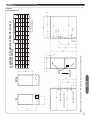
➀ May require 3” to 4” or 3” to 5” adapter.
➁ May be 0” with type B vent.
➂ May be 1” with type B vent.
0
0
0
0
0
0
Back
REDUCED CLEARANCE (IN.)
CLEARANCE TO COMBUSTIBLE MATERIAL (INCHES)
DOWNFLOW MODELS
FIGURE 3
DOWNFLOW DIMENSIONS
9
DUCTING
Proper air flow is required for the correct operation of this
furnace. Restricted air flow can cause erratic operation and
can damage the heat exchanger. The duct system must
carry the correct amount of air for heating and cooling if
summer air conditioning is used.
! WARNING
SOME HEATING AIRFLOW VALUES MAY BE
HIGHER THAN THOSE REQUIRED FOR COOLING.
BE SURE TO SIZE DUCT FOR THE MAXIMUM POSSIBLE AIRFLOW VALUE.
SIZE AIRFLOW DISTRIBUTION SYSTEM TO ACCEPTABLE INDUSTRY STANDARDS AND METHODS. TOTAL STATIC PRESSURE DROP OF THE AIR
DISTRIBUTION SYSTEM SHOULD NOT EXCEED .8
INCHES W.C. THIS WILL INCLUDE ANY AIR CONDITIONER COIL, AIR FILTRATION SYSTEM, ZONING
SYSTEM, DUCTWORK, ETC. REFER TO ADDED
EQUIPMENT TECHNICAL INFORMATION TO OBTAIN
PRESSURE DROP INFORMATION WHEN EQUIPMENT IS OPERATING AT RECOMMENDED HEATING OR COOLING CFMS.
IMPORTANT: When using outside air, design and adjust
the system to maintain a return air temperature ABOVE
55° F during the heating season.
NOTE: Return air grilles and warm air registers must not
be obstructed or closed.
DOWNFLOW INSTALLATIONS
! WARNING
Ducting
A DOWNFLOW INSTALLATION IS CERTIFIED FOR
INSTALLATION ON A NON-COMBUSTIBLE FLOOR.
USE THE SPECIAL BASE SPECIFIED ON THE FURNACE CLEARANCE LABEL. FAILURE TO INSTALL
THE SPECIAL BASE MAY RESULT IN FIRE, PROPERTY DAMAGE, PERSONAL INJURY OR DEATH.
THIS BASE IS AVAILABLE AS AN ACCESSORY.
1. Position the unit to minimize long runs of duct or runs
of duct with many turns and elbows.
2. If summer air conditioning is desired, position the indoor coil on the supply-air side of the unit. Ensure that
no air can bypass this coil.
3. If installing on a combustible floor and not using an
air conditioning plenum, install the special non-combustible floor base. See Table 1 and Figure 5.
4. Connect the furnace to the supply air plenum. See Figure 4.
10
5. Connect the return air ducting to the return air opening
at the top of the unit. Make the connection air tight to
prevent the migration of toxic fumes and odors including carbon monoxide from migrating into the living
space from an adjacent fuel-burning appliance.
NOTE: In downflow configuration, side return air cut
out is not permitted. Do not take return air from the
back of the unit.
6. If a filter is installed near the furnace, be sure to
have adequate space for installation and removal
of the unit filter.
NOTE: DO NOT take return air from furnace rooms,
garages or cold areas. Avoid return air from utility
rooms, kitchens, laundry rooms and bathrooms.
! WARNING
BLOWER AND BURNERS MUST NEVER BE OPERATED
WITHOUT THE BLOWER DOOR IN PLACE. THIS IS TO
PREVENT DRAWING GAS FUMES (WHICH COULD CONTAIN HAZARDOUS CARBON MONOXIDE) INTO THE
HOME THAT COULD RESULT IN PERSONAL INJURY OR
DEATH.
FIGURE 4
DUCTING
TABLE 1
NON-COMBUSTIBLE FLOOR BASES
Floor Base
No.
Size
Cabinet
RXGC-B14
14
RXGC-B17
17
RXGC-B21
21
RXGC-B24
24
FIGURE 5
NON-COMBUSTIBLE FLOOR BASE INSTALLATION INSTRUCTIONS
COMBUSTIBLE
COMBUSTIBLE
FLOOR
FLOOR
MATERIAL
MATERIAL
NON-COMBUSTIBLE
NON-COM
FLOOR BASE
FLOOR
BASE
A
21 5/8"
FLOOR
FLOOR CUTOUT
CUTOUT
DIMENSIONS
DIMENSIONS
21 5/8"
FLOOR
BASE NO.
CABINET
WIDTH
FLOOR CUTOUT
DIMENSION “A”
RXGC-B14
14.0”
13.4”
RXGC-B17
17.5”
17.0”
RXGC-B21
21.0”
20.0”
RXGC-B24
24.5”
23.5”
ST-A1194-43-00
Ducting
11
Combustion Air
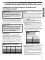
COMBUSTION AND VENTILATION AIR
COMBUSTION AIR REQUIREMENTS
IMPORTANT: This is not a direct vent furnace. Review venting
instructions before installing.
! WARNING
THIS FURNACE AND ANY OTHER FUEL-BURNING APPLIANCE MUST BE PROVIDED WITH ENOUGH FRESH AIR
FOR PROPER COMBUSTION AND VENTILATION OF THE
FLUE GASES. MOST HOMES WILL REQUIRE THAT OUTSIDE AIR BE SUPPLIED INTO THE FURNACE AREA. FAILURE TO DO SO CAN CAUSE DEATH FROM CARBON
MONOXIDE POISONING.
! WARNING
ADEQUATE FACILITIES FOR PROVIDING AIR FOR COMBUSTION AND VENTILATION MUST BE PROVIDED IN ACCORDANCE WITH SECTION 5.3, AIR FOR COMBUSTION
AND VENTILATION, OF THE NATIONAL FUEL GAS CODE,
ANSI, Z223.1 LATEST EDITION OR APPLICABLE PROVISIONS FOR THE LOCAL BUILDING CODES, AND NOT
OBSTRUCTED SO AS TO PREVENT THE FLOW OF AIR TO
THE FURNACE.
1. IMPORTANT: Air for combustion and ventilation must not
come from a corrosive atmosphere. Any failure due to corrosive elements in the atmosphere is excluded from warranty
coverage.
2. Combustion air must be free of acid forming chemicals; such
as sulphur, fluorine and chlorine. These elements are found in
aerosol sprays, detergents, bleaches, cleaning solvents, air
fresheners, paint and varnish removers, refrigerants and many
other commercial and household products. Vapors from these
products when burned in a gas flame form acid compounds.
The acid compounds increase the dew point temperature of
the flue products and are highly corrosive after they condense.
3. The following types of installation may require OUTDOOR AIR
for combustion, due to chemical exposures:
• Commercial buildings
• Buildings with indoor pools
• Furnaces installed in laundry rooms
• Furnaces in hobby or craft rooms
• Furnaces installed near chemical storage areas.
4. If combustion air is exposed to the following substances (but
not limited to the following), it should not be used and the furnace may require outdoor air for combustion.
• Permanent wave solutions
• Chlorinated waxes and cleaners
• Chlorine-based swimming pool chemicals
• Water softening chemicals
• De-icing salts or chemicals
• Carbon tetrachloride
• Halogen type refrigerants
• Cleaning solvents (such as perchloroethylene)
• Printing inks, paint removers, varnishes, etc.
• Hydrochloric acid
• Cements and glues
• Antistatic fabric softeners for clothes dryers
• Masonry curing and acid washing materials
12
! WARNING
ALL FURNACE INSTALLATIONS MUST COMPLY WITH
THE NATIONAL FUEL GAS CODE AND LOCAL CODES TO
PROVIDE ADEQUATE COMBUSTION AND VENTILATION
AIR FOR THE FURNACE. FAILURE TO DO SO CAN CREATE HAZARDOUS CONDITIONS RESULTING IN PROPERTY DAMAGE, BODILY INJURY OR DEATH FROM
SMOKE, FIRE OR CARBON MONOXIDE.
Combustion air requirements are determined by whether
the furnace is in an open (unconfined) area or in a confined space such as a closet or small room.
When the furnace is installed in the same space with other
gas appliances, such as a water heater, be sure there is an
adequate supply of combustion and ventilation air for the
furnace and the other appliances. Do not delete or reduce
the combustion air supply required by the other gas appliances in this space. See Z223.1, National Fuel Gas Code
(NFPA 54). An unconfined space must have at least 50
cubic feet (volume) for each 1,000 BTUH of the total input of
all appliances in the space. If the open space containing the
appliances is in a building with tight construction (contemporary construction), outside air may still be required for the
appliances to burn and vent properly. Outside air openings
should be sized the same as for a confined space.
IMPORTANT: ONLY THE CURRENT VENT INSTRUCTIONS APPLY. All gas furnaces cannot be commonvented.
OVERTEMPERATURE SAFETY
SWITCHES
Furnaces are equipped with safety switches in the burner
compartment to protect against over-temperature conditions caused by inadequate combustion air supply. The
switches are located in the burner compartment. If a switch
is tripped it must be manually reset after clearing the fault
condition which caused it to open.
! WARNING
DO NOT BYPASS, JUMPER, OR REMOVE ANY SAFETY
SWITCH FROM THE FURNACE CONTROL CIRCUIT. IF A
SAFETY SWITCH CAUSES THE FURNACE TO SHUT
DOWN OR OPERATE INTERMITTENTLY, IT IS AN INDICATION OF A POTENTIAL SAFETY HAZARD THAT MUST BE
ADDRESSED BY A QUALIFIED TECHNICIAN, SERVICE
AGENCY OR THE GAS SUPPLIER. DO NOT RESET
SAFETY CONTROLS WITHOUT CORRECTIVE ACTION
AND/OR VERIFICATION OF PROPER SAFE OPERATION
BY A QUALIFIED INSTALLER, SERVICE AGENCY OR THE
GAS SUPPLIER.
REPLACE ANY SAFETY CONTROL COMPONENT WITH
IDENTICAL OEM REPLACEMENT PARTS ONLY.
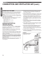
COMBUSTION AND VENTILATION AIR (cont.)
FURNACE LOCATED IN A CONFINED
SPACE
! WARNING
ALL FURNACE INSTALLATIONS MUST COMPLY WITH
THE NATIONAL FUEL GAS CODE, NFPA 54 AND LOCAL
CODES TO PROVIDE ADEQUATE COMBUSTION AND
VENTILATION AIR FOR THE FURNACE. FAILURE TO DO
SO CAN RESULT IN EXPLOSION, FIRE, PROPERTY DAMAGE, CARBON MONOXIDE POISONING, PERSONAL INJURY OR DEATH.
For improved indoor air quality, added safety and product performance we recommend direct vent type installations. If non-direct type vent system is used, the requirements for combustion
air must be provided as identified in the National Fuel Gas Code.
Combustion air requirements are determined by whether the furnace is in an open (unconfined) area or in a confined space such
as a closet or small room.
! WARNING
READ AND FOLLOW THE GENERAL VENTING REQUIREMENTS AND GUIDELINES OF THIS MANUAL FOR ADDITIONAL VENTING REQUIREMENTS PERTAINING TO ALL
FURNACE INSTALLATIONS (INCLUDING DIRECT AND
NON-DIRECT VENTING). FAILURE TO FOLLOW ALL INSTRUCTIONS IN THIS MANUAL CAN RESULT IN EQUIPMENT FAILURE, EQUIPMENT DAMAGE, PROPERTY
DAMAGE, PERSONAL INJURY OR DEATH.
FURNACE LOCATED IN AN UNCONFINED SPACE
USING INDOOR AIR FOR COMBUSTION:
An unconfined space must have at least 50 cubic feet for each
1,000 BTUH of total input for all appliances in the space. Table 2
below specifies minimum space requirements and a few examples of the room sizes required for different inputs. The sizes are
based on 8-foot ceilings.
If the open space containing the furnace is in a building with tight
construction, outside air may still be required for the furnace to
operate and vent properly. Outside air openings should be sized
the same as for a confined space.
Input
(BTUH)
Minimum Area
with 8
Ceilings (sq )
50,000
75,000
100,000
125,000
150,000
2,500
3,750
5,000
6,300
7,500
313
470
625
790
940
Typical Room
Size w/ 8'
Ceilings ( x )
16
24
32
36
32
x
x
x
x
x
20
20
20
30
30
A. USING INDOOR AIR FOR COMBUSTION:
IMPORTANT: Air should not be taken from a heated space
with a fireplace, exhaust fan or other device that may produce negative pressure.
If combustion air is taken from the heated area, the openings
must each have at least 100 square inches of free area.
Each opening must have at least one square inch of free
area for each 1,000 BTUH of total input in the space. Table 3
shows some typical examples of openings required for combustion air openings required for a confined space.
TABLE3:8:MINIMUM
MINIMUM
FREE
AREA
TABLE
FREE
AREA
OPENINGREQUIRED
REQUIRED
FOR
OPENING
FOR
A A
FURNACE
ININ
AA
FURNACELOCATED
LOCATED
CONFINED
SPACE
USING
CONFINED SPACE USING
INDOOR
INDOORAIR
AIRFOR
FORCOMBUSTION.
COMBUSTION.
Input (BTUH)
Free Area for Each
Opening (sq inches)
50,000
75,000
100,000
125,000
150,000
100
100
100
130
150
B. USING OUTDOOR AIR FOR COMBUSTION:
TABLE
SPACE
REQUIREMENTS
TABLE2:7:MINIMUM
MINIMUM
SPACE
REQUIREMENTS
FOR
UNCONFINED
SPACE,
NON-DIRECT
VENT
FOR UNCONFINED SPACE, NON-DIRECT
VENT*
Minimum
Space
(Cubic Ft)
A confined space is defined as any space for a given furnace input
rating which is smaller than that which is specified in Table 2 as
minimum for an “unconfined” space. If the space is less than that
specified in this table, the space is defined as “confined”.
If the space is small enough to be designated as “confined”, it
must have openings into the space which are located in accordance with the requirements set forth in the following subsections
A and B. Size connected to the heated area or to the outside, and
by the input of ALL appliances in the space.
If the confined space is within a building with tight construction,
combustion air must be taken from outdoors or from an area
freely communicating with the outdoors.
30
IMPORTANT: Do not take air from an attic space that is
equipped with power ventilation.
The confined space must communicate with the outdoors in
accordance with Methods 1 or 2 below. The minimum dimension of air openings shall not be less than 3 inches. Where
ducts are used, they shall be of the same cross-sectional
area as the free area of the openings to which they connect.
METHOD 1:
Two permanent openings, one located within 12 inches of the
top and one located within 12 inches of the bottom of the enclosure, shall be provided. The openings shall communicate
directly, or by ducts, with the outdoors or spaces (crawl or
attic) that freely communicate with the outdoors.
13
Combustion Air
COMBUSTION AIR REQUIREMENTS: CONFINED AND
UNCONFINED SPACES
Combustion Air
COMBUSTION AND VENTILATION AIR (cont.)
COMBUSTION AIR REQUIREMENTS: CONFINED AND
UNCONFINED SPACES
TABLE 4:
9: MINIMUM
FREE AREA
AREA REQUIRED
REQUIRED
TABLE
MINIMUM FREE
FOR EACH
EACH OPENING
OPENING (WHEN
(WHEN TWO
TWOOPENINGS
OPENINGS
FOR
ARE USED)
USED) WITH
ARE
WITH A
A FURNACE:
FURNACE:
1. LOCATED IN A CONFINED SPACE
2.
USING OUTDOOR
OUTDOOR AIR
2. USING
AIR FOR
FOR COMBUSTION
COMBUSTION
3.
COMMUNICATING
DIRECTLY
3. COMMUNICATING DIRECTLY TO
TO THE
THE
3. OUTSIDE
OUTSIDE THROUGH
THROUGH AN
OPENING
AN OPENING OR
OR
3. THROUGH
THROUGH A
A VERTICAL
VERTICALVENT
DUCT.DUCT.*
Total Input for
ALL Gas
Appliances
(BTUH)
Free Area for
Each Opening
when 2 Separate
Openings are
used (sq inches)
Round Pipe Duct
Diameter ( Ver cal
Duct Only) (inches)
50,000
75,000
100,000
125,000
150,000
13
19
25
32
38
5
5
6
8
8
A. Where directly communicating with the outdoors through an
opening or where communicating to the outdoors through
vertical ducts as shown in Figure 7, each opening shall have
a minimum free area of 1 square inch for each 4,000 BTUH
of total appliance input rating of all equipment in the enclosure. Table 4 specifies the minimum area for each of the 2
combustion air openings and minimum round duct diameter
for direct openings and vertical ducting only.
B. Where communicating with the outdoors through horizontal ducts, each opening shall have a minimum free area of 1
square inch for each 2,000 BTUH of total appliance input rating of all equipment in the enclosure (see Figure 8). Table 5
TABLE
FREE
TABLE 6:
11:MINIMUM
MINIMUM
FREEAREA
AREAREQUIRED
REQUIRED
FOR
EACH
OPENING
(WHEN
OPENINGS
FOR AN
OPENING
(WHEN
ONTWO
E OPENING
IS
ARE
USED)
WITH
A
FURNACE:
USED) WITH A FURNACE:
1.
1. LOCATED
LOCATED IN
IN A
A CONFINED
CONFINED SPACE
SPACE
2.
USING
OUTDOOR
AIR
FOR
2. USING OUTDOOR AIR FOR COMBUSTION
COMBUSTION
3.
COMMUNICATING
DIRECTLY
3. COMMUNICATING DIRECTLYTO
TOTHE
THE
3. OUTSIDE
THROUGH
A
HORIZONTAL
DUCT.
OUTSIDE.*
Total Input for
ALL Gas
Appliances
(BTUH)
Free Area for an
Opening when 1
Opening is used
(sq inches)
Round Pipe Duct
Diameter (inches)
50,000
75,000
100,000
125,000
150,000
25
38
50
63
75
6
8
8
10
10
specifies the minimum area for each of the 2 combustion air
openings and minimum round duct diameter for horizontal
ducting only.
METHOD 2:
One permanent opening located within 12 inches of the top of
the enclosure, shall be permitted where the equipment has
clearances of at least 1 inch from the sides and back and 6
inches from the front of the appliance. The opening shall directly communicate with the outdoors or communicate
through a vertical or horizontal duct to the outdoors or spaces
(crawl or attic) that freely communicate with the outdoors,
and shall have a minimum of:
AIR FROM HEATED
SPACE
FIGURE
6
AIR FROM HEATED SPACE
TABLE
FREE
TABLE 5:
10:MINIMUM
MINIMUM
FREEAREA
AREAREQUIRED
REQUIRED
FOR
FOR EACH
EACH OPENING
OPENING(WHEN
(WHENTWO
TWOOPENINGS
OPENINGS
ARE
USED)
WITH
A
FURNACE:
ARE USED) WITH A FURNACE:
1.
1. LOCATED
LOCATED IN
IN AA CONFINED
CONFINEDSPACE
SPACE
2.
USING
OUTDOOR
AIR
FOR
2. USING OUTDOOR AIR FOR COMBUSTION
COMBUSTION
3.
3. COMMUNICATING
COMMUNICATINGDIRECTLY
DIRECTLYTO
TOTHE
THE
3. OUTSIDE
THROUGH
A
HORIZONTAL
OUTSIDE THROUGH A HORIZONTAL DUCT.
DUCT.
Total Input for
ALL Gas
Appliances
(BTUH)
50,000
75,000
100,000
125,000
150,000
Free Area for
Each Opening
when 2 Separate
Openings are
used (sq inches)
25
38
50
63
75
12”
MAX
Round Pipe Duct
Diameter
(Horizontal Duct
Only) (inches)
6
8
8
10
10
GAS
WATER
HEATER
FURNACE
12”
MAX
NOTE:
EACH OPENING SHALL
HAVE A FREE AREA OF
NOT LESS THAN ONE
SQUARE INCH PER
1,000 BTU PER HOUR OF
THE TOTAL INPUT
RATING OF ALL
EQUIPMENT IN THE
ENCLOSURE, BUT NOT
LESS THAN 100
SQUARE INCHES.
ST-A1227-01-00
14
COMBUSTION AND VENTILATION AIR (cont.)
FIGURE 7
VENT PENETRATIONS
FOR NON DIRECT VENT FURNACES
AIR FROM ATTIC/CRAWL SPACE
NON-DIRECT VENT
AIR FROM ATTIC
OR CRAWL
SPACE
1 SQ. INCH PER
4000 BTUH
OUTLET AIR
GAS
WATER
HEATER
FURNACE
GABLE
VENT
VENT PENETRATIONS
FOR NON DIRECT VENT FURNACES
AIR FROM ATTIC/CRAWL SPACE
NON-DIRECT VENT
OUTSIDE AIR
USING A
HORIZONTAL
DUCT
VENTILATED
ATTIC GABLE OR
SOFFIT VENTS
OPTIONAL 1 SQ. INCH PER 4000 BTUH INLET AIR
OUTLET AIR
IN ATTIC
MUST BE
ABOVE
INSULATION
FIGURE 8
Combustion Air
COMBUSTION AIR REQUIREMENTS: CONFINED AND
UNCONFINED SPACES
OUTLET AIR
1 SQ. INCH PER
4000 BTUH
OUTLET AIR 1 SQ. INCH
PER 2000 BTUH
GAS
WATER
HEATER
INLET AIR
1 SQ. INCH PER
4000 BTUH
12” MAX
1 SQ. INCH PER
4000 BTUH INLET AIR
ST-A1227-02
A. 1 Square inch for each 3,000 BTUH of the total input rating of all equipment located in the enclosure
and
B. Not less than the sum of the areas of all vent connectors
in the confined space.
If the unit is installed where there is an exhaust fan, sufficient
ventilation must be provided to prevent the exhaust fan from creating negative pressure.
It is also acceptable to run the condensate drain (or refrigerant) line access over the air intake hole as long as a 1" minimum clearance is maintained.
Combustion air openings must not be restricted in any manner.
FURNACE
12”
MAX
INLET AIR 1 SQ. INCH
PER 2000 BTUH
ST-A1227-03
IMPORTANT: If the furnace is in a location with an exhaust fan,
there must be sufficient ventilation to prevent the exhaust fan
from creating a negative pressure in the room.
Combustion air openings must NOT BE RESTRICTED in any
manner.
CONSULT LOCAL CODES FOR SPECIAL REQUIREMENTS.
B: Method 3
For the optimum in quiet operation, attic air may be brought directly to the furnace.
IMPORTANT: In applications using Method 3 for combustion air,
the attic must be ventilated by gable or soffit vents.
IMPORTANT: When indoor combustion air is used, the inlet air
opening at the furnace must be protected from accidental blockage.
15
Combustion Air
COMBUSTION AND VENTILATION AIR (cont.)
VENTING
GENERAL INFORMATION
IMPORTANT APPLICATION NOTES
The furnace must be vented in accordance with these instructions,
National Fuel Gas Code, ANSI Z223.1 and requirements or codes
of the local utility or other authority having jurisdiction.
When the furnace is used as a replacement, the existing vent
system should be inspected to assure that there are no obstructions, blockage, or any signs of corrosion and is properly sized for
use with this furnace.
! WARNING
DEVICES ATTACHED TO THE FLUE OR VENT FOR THE
PURPOSE OF REDUCING HEAT LOSS UP THE CHIMNEY
HAVE NOT BEEN TESTED AND HAVE NOT BEEN INCLUDED IN THE DESIGN CERTIFICATION OF THIS FURNACE. WE, THE MANUFACTURER, CANNOT AND WILL
NOT BE RESPONSIBLE FOR INJURY OR DAMAGE
CAUSED BY THE USE OF SUCH UNTESTED AND/OR UNCERTIFIED DEVICES, ACCESSORIES OR COMPONENTS.
DRAFT INDUCER
! WARNING
VENT PIPE ATTACHING HOLES MUST BE PREDRILLED
IN THE 1/8” DIAMETER HOLES THROUGH THE VENT PIPE
AND COLLAR AND USE #8 SCREWS TO ATTACH. SEE
FIGURE 10. FAILURE TO FOLLOW THIS WARNING CAN
CAUSE RECIRCULATION OF FLUE PRODUCTS CAUSING
CARBON MONOXIDE POISONING RESULTING IN PERSONAL INJURY OR DEATH.
FURNACE CATEGORY INFORMATION
This furnace is shipped as a Category I type induced draft furnace. A Category I furnace operates with a nonpositive vent pressure and has a vent gas temperature at least 140°F above the
dew point of the vent gases. A Category I type may be a draft
hood equipped furnace or have a fan assisted combustion system (induced draft). The inducer is used to pull flue products
through the combustion chamber and as they leave the furnace,
most of the energy has been dissipated. The buoyant effect of the
flue gases provides venting to the outdoors.
During the off cycle, the inducer is off and there is very little flow
through the vent, cooling the vent. During the on cycle there is no
dilution airflow, as with a draft hood type furnace. Although the
vent heats up rapidly without dilution air, the flue products contain
more water vapor, which results in a higher dew point temperature. It is most important that you follow the guidelines in these
instructions to prevent the possible formation of condensation in
the venting system.
As a Category I furnace it may be vented vertically with type B-1
vent pipe and also may be common vented, as described in
these instructions.
16
NOTE: When the vent table permits more than one diameter of
pipe for a connector or vent, the smallest permitted diameter
must be used.
Vent pipe may be type “B-1,” either rigid or suitable flexible construction that carries a U.L. listing.
Common venting is allowed with vertical B-1 vent systems, and
lined masonry chimneys. Follow the National Fuel Gas Code,
ANSI Z223.1 for proper installation practices.
NOTE: Follow combustion air instructions as outlined in this manual.
Single wall vent connectors to “B-1 vent or masonry chimneys”
may be used under the guidelines of the National Fuel Gas Code,
ANSI Z223.1.
The entire length of the vent connector shall be readily accessible for inspection, cleaning and replacement.
“B-1” VERTICAL VENTING
NOTE: Refer to the National Fuel Gas Code, ANSI Z223.1.
Type “B-1” vents must be installed in accordance with the terms
of their listings and the vent manufacturer’s instructions.
“B-1” vents must be supported and spaced in accordance with
their listings and the manufacturer’s instructions. All vents must
be supported to maintain their minimum clearances from combustible material.
VERTICAL VENTING
Categorized
Furnace Vent
Input
Size Recommended
(See NFGC)
50K
3”
75K
*4”
100K
*4”
125K
*5”
150K
*5”
*NOTE: All furnaces have a 3” vent connection as shipped from the factory. A 3” to 4” or 3” to 5” vent transition may be required when vertically
vented or common vented with metal vent pipes. THE VENT TRANSITION CONNECTION MUST BE MADE AT THE FURNACE VENT EXIT. It
must originate with an adapter if required, at the furnace flue collar and
terminate either in a listed cap or roof assembly. When common venting,
the vent connector size may differ from the above diameters depending
on application. See National Fuel Gas Code ANSI Z223.1 or latest edition
tables.
COMBUSTION AND VENTILATION AIR (cont.)
Single appliance venting of a fan assisted furnace into a tile-lined
masonry chimney is prohibited. The chimney must be lined with
either Type B vent or with a listed, single wall system. Reference
National Fuel Gas Code, ANSI Z223.1. See Figure 11 for typical
B-1 vent chase.
! WARNING
DO NOT CONNECT THIS FURNACE TO A CHIMNEY USED
TO VENT A SOLID FUEL APPLIANCE (WOOD OR COAL).
VENTING WITH A SOLID FUEL APPLIANCE CAN LEAD TO
IMPROPER FUNCTIONING OF THE UNIT, AND DUE TO
SOOTING, THE POSSIBILITY OF FIRE RESULTING IN
PROPERTY DAMAGE, PERSONAL INJURY OR DEATH.
SPECIAL VENT SYSTEMS (SVS)
IMPORTANT: It is THE FURNACE MANUFACTURER’s position
now that new installations of any HTPV pipe used in a category
III vent application, including Selkirk’s Selvent™ II HTPV product, should cease immediately.
F
FIGURE 9
TYPICAL VENTING WITH “B-1” VENT
LISTED CAP
FIGURE 10
ATTACHING TO FLUE PIPE OF UNIT OUTLET
FIGURE 17
VENT PIPE
LISTED GAS VENT
FLUE PIPE
“H” - MINIMUM ALLOWABLE HEIGHT
FROM ROOF TO DISCHARGE OPENING
PRE-DRILL
ATTACHING
HOLES
X
12
ROOF PITCH = X/12
ST-A1220-24
ST-A1220-24
ROOF PITCH
FLAT TO 6/12
OVER 6/12 TO 7/12
OVER 7/12 TO 8/12
OVER 8/12 TO 9/12
OVER 9/12 TO 10/12
OVER 10/12 TO 11/12
OVER 11/12 TO 12/12
OVER 12/12 TO 14/12
OVER 14/12 TO 16/12
OVER 16/12 TO 18/12
OVER 18/12 TO 20/12
OVER 20/12 TO 21/12
“H” (MIN.) FT.
1.0
1.25
1.5
2.0
2.5
3.25
4.0
5.0
6.0
7.0
7.5
8.0
ST-A1227-05
17
Combustion Air
VERTICAL VENT SYSTEMS:
1. A gas vent shall terminate above the roof surface with a listed
cap or listed roof assembly. Gas vents 12 inches in size or
smaller with listed caps shall be permitted to be terminated in
accordance with Figure 9, provided they are at least 8 feet
from a vertical wall or similar obstruction. All other gas vents
shall terminate not less than 2 feet above the highest point
where they pass through the roof and at least 2 feet higher
than any portion of a building within 10 feet.
2. A type B-1 gas vent shall terminate at least 5 feet in vertical
height above the highest connected equipment draft hood or
flue collar.
3. Must rise 1/4” per foot away from the furnace on horizontal runs
and be supported with straps or hangers so it has no sags or
dips. Supports at 4 foot intervals and at all elbows are recommended.
4. The vent connector must be mechanically fastened to the flue
outlet of the furnace with at least (2) sheet metal screws except vent connectors that are B-1 material. These shall be assembled in accordance with the manufacturer’s instructions.
See Figure 10.
5. Any angle greater than 45 degrees from the vertical is considered horizontal. The total horizontal distance of a vent plus the
horizontal vent connector serving draft-hood equipped appliances shall not be greater than 75 percent of the vertical
height of the vent.
Combustion Air
COMBUSTION AND VENTILATION AIR (cont.)
POWER VENT SYSTEMS
When vertical venting is not possible, the only acceptable method
for horizontal venting is with the use of Tjernlund model GPAK1TR or Field Controls models SWG-4R power venter. Type B
vent pipe and fittings must be used. Common venting is not permitted
All application and installation instructions supplied with the
power venter must be followed.
Please address all questions regarding power venter installation,
agency listings and furnace model compatibility to:
Tjernlund Products, Inc.
(800) 255-4208 or (612) 426-2993
Field Controls L.L.C.
(800) 742-8368 or (919) 522-0214
EXISTING VENT SYSTEMS
IMPORTANT RETROFIT
VENTING INSTRUCTIONS
If this furnace is a replacement installation, ALWAYS INSPECT
the existing vent system to be sure there are no obstructions,
blockages, or signs of corrosion.
When the existing furnace is removed from a venting system
serving other appliances, the venting is likely to be too large to
properly vent the remaining attached appliances.
The following steps shall be followed with each appliance that remains connected to the common venting system, while the other
appliances that remain connected to the common venting systems are not in operation.
NOTE: When the vent table permits more than one diameter
of pipe for a connector or vent, the smallest permitted diameter must be used.1. Seal any unused openings in the common venting system.
NOTE: Ensure existing venting system complies with latest addition of National Fuel Gas Code ANSI Z223.1 and all local
codes/regulations.
18
1. Visually inspect the venting system for proper size and horizontal pitch and determine that there is no blockage, restriction, leakage, corrosion or other deficiencies which could
cause an unsafe condition.
2. Insofar as is practical, close all building doors, windows and all
doors between the space where the appliances remaining connected to the common venting system are located. Turn on
clothes dryers and any appliance not connected to the common venting system. Turn on any exhaust fans, such as range
hoods and bathroom exhausts, so they will operate at maximum speed. Do not operate a summer exhaust fan. Close fireplace dampers.
3. Follow the lighting instructions. Place the appliance being inspected into operation. Adjust the thermostat so the appliance
will operate continuously.
4. Test for spillage at the draft hood relief opening after 5 minutes
of main burner operation. Use the flame of a match or candle,
or smoke from a cigarette, cigar, or pipe.
5. After it has been determined that each appliance that remains
connected to the common venting system properly vents
(when tested as outlined above) return doors, windows, exhaust fans, fireplace dampers and any other gas-burning appliance to their previous conditions of use.
6. If improper venting is observed during any of the above tests,
the common venting system must be resized. Refer to National
Fuel Gas Code, ANSI Z223.1.
FIGURE 11
DEDICATED VENTING THROUGH
CHIMNEY WITH “B-1” VENT
GAS SUPPLY
GAS SUPPLY AND PIPING
NATURAL GAS AND PROPANE
(LIQUEFIED PETROLEUM GAS / LPG)
SAFETY
IMPORTANT SAFETY INFORMATION
GAS SUPPLY
• FURNACES USING PROPANE GAS ARE DIFFERENT FROM NATURAL GAS MODELS. A NATURAL
GAS HEATER WILL NOT FUNCTION SAFELY ON
PROPANE AND VICE VERSA. CONVERSIONS OF
HEATER GAS TYPE SHOULD ONLY BE MADE BY
QUALIFIED INSTALLERS USING FACTORY SUPPLIED COMPONENTS. THE FURNACE SHOULD
ONLY USE THE FUEL TYPE IN ACCORDANCE
WITH LISTING ON RATING PLATE. ANY OTHER
FUEL USAGE WILL RESULT IN DEATH OR SERIOUS PERSONAL INJURY FROM FIRE AND/OR EXPLOSION.
• BOTH NATURAL GAS AND PROPANE HAVE AN
ODORANT ADDED TO AID IN DETECTING A GAS
LEAK. SOME PEOPLE MAY NOT PHYSICALLY BE
ABLE TO SMELL OR RECOGNIZE THIS ODORANT.
IF YOU ARE UNSURE OR UNFAMILIAR WITH THE
SMELL OF NATURAL GAS OR PROPANE, ASK
YOUR LOCAL GAS SUPPLIER. OTHER CONDITIONS, SUCH AS “ODORANT FADE,” WHICH
CAUSES THE ODORANT TO DIMINISH IN INTENSITY, CAN ALSO HIDE, CAMOUFLAGE, OR OTHERWISE MAKE DETECTING A GAS LEAK BY
SMELL MORE DIFFICULT.
• UL OR CSA RECOGNIZED FUEL GAS DETECTORS
ARE RECOMMENDED IN ALL ENCLOSED
PROPANE AND NATURAL GAS APPLICATIONS
WHEREIN THERE IS A POTENTIAL FOR AN EXPLOSIVE MIXTURE OF FUEL GAS TO ACCUMULATE.
FUEL DETECTOR INSTALLATION SHOULD BE IN
ACCORDANCE WITH THE DETECTOR MANUFACTURER’S RECOMMENDATIONS AND/OR LOCAL
LAWS, RULES, REGULATIONS, OR CUSTOMS.
• BEFORE ATTEMPTING TO LIGHT THE FURNACE,
MAKE SURE TO LOOK AND SMELL FOR GAS
LEAKS. USE A SOAPY SOLUTION TO CHECK ALL
GAS FITTINGS AND CONNECTIONS.
BUBBLING AT A CONNECTION INDICATES A LEAK
THAT MUST BE CORRECTED. WHEN SMELLING TO
DETECT A GAS LEAK, BE SURE TO ALSO SNIFF
NEAR THE FLOOR. PROPANE GAS IS HEAVIER
THAN AIR AND TENDS TO COLLECT AT LOWER
LEVELS MAKING IT MORE DIFFICULT TO SMELL AT
NOSE LEVEL. NATURAL GAS IS LIGHTER THAN AIR
(Continued on next column)
19
Gas Supply
! WARNING
AND WILL RISE, POSSIBLY ACCUMULATING IN
HIGHER PORTIONS OF THE STRUCTURE.
• IF A GAS LEAK IS PRESENT OR SUSPECTED:
- DO NOT ATTEMPT TO FIND THE CAUSE YOURSELF.
- NEVER USE AN OPEN FLAME TO TEST FOR GAS
LEAKS. THE GAS CAN IGNITE RESULTING IN
DEATH, PERSONAL INJURY, OR PROPERTY
DAMAGE.
- DO NOT TRY TO LIGHT ANY APPLIANCE.
- DO NOT TOUCH AND ELECTRICAL SWITCH.
- DO NOT USE ANY PHONE IN YOUR BUILDING.
- LEAVE THE BUILDING IMMEDIATELY AND CALL
THE GAS SUPPLIER FROM A NEIGHBOR’S
PHONE. FOLLOW THE GAS SUPPLIER’S INTRUCTIONS.
- IF YOU CANNOT REACH YOUR GAS SUPPLIER,
CALL THE FIRE DEPARTMENT.
- DO NOT RETURN TO THE BUILDING UNTIL AUTHORIZED BY THE GAS SUPPLIER OR FIRE DEPARTMENT.
• SHOULD OVERHEATING OCCUR OR THE GAS
SUPPLY FAIL TO SHUT OFF, TURN OFF THE MANUAL GAS CONTROL VALVE TO THE FURNACE.
• CONSULT WITH THE LOCAL BUILDING DEPARTMENT AND FUEL GAS SUPPLIER BEFORE INSTALLING THE HEATER:
- THE INSTALLATION AND PURGING OF GAS PIPING MUST CONFORM TO LOCAL CODES, UTILITY COMPANY REQUIREMENTS, AND THE
LATEST EDITION OF NATIONAL FUEL GAS
CODE (NFGC) - ANSI Z223.1/NFPA 54.
- LP FURNACES SHOULD NOT BE INSTALLED
BELOW GRADE (IN A BASEMENT FOR EXAMPLE) IF SUCH INSTALLATION IS PROHIBITED BY
FEDERAL, STATE, PROVINCIAL, AND/OR LOCAL
LAWS, RULES, REGULATIONS, OR CUSTOMS.
- INSTALLATION OF A GAS PRESSURE REGULATOR MAY BE REQUIRED IN THE GAS SUPPLY
LINE. THE REGULATOR SHOULD NOT EXCEED
THE MAXIMUM SUPPLY PRESSURE LISTED ON
THE FURNACE RATING PLATE. DO NOT USE AN
INDUSTRIAL-TYPE GAS REGULATOR.
- FOLLOW ALL LOCAL CODES AND SECTION 8.3
OF NFGC WITH REGARD TO PURGING OF GAS
PIPING TO ENSURE THAT THE AIR AND/OR FUEL
GAS IN THE GAS PIPING IS PROPERLY VENTED
TO A LOCATION WHERE AN EXPLOSIVE MIXTURE CANNOT ACCUMULATE.
GAS SUPPLY
GAS PIPING
Gas Supply
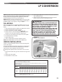
! WARNING
THIS FURNACE IS EQUIPPED AT THE FACTORY
FOR USE ON NATURAL GAS ONLY. CONVERSION
TO LP GAS REQUIRES A SPECIAL KIT IS AVAILABLE AT THE DISTRIBUTOR. FAILURE TO USE THE
PROPER CONVERSION KIT CAN CAUSE FIRE,
CARBON MONOXIDE POISONING, EXPLOSION,
PROPERTY DAMAGE, PERSONAL INJURY OR
DEATH. SEE THE CONVERSION KIT INDEX SUPPLIED WITH THE FURNACE. THIS INDEX IDENTIFIES THE PROPER LP GAS CONVERSION KIT
REQUIRED FOR EACH PARTICULAR FURNACE.
IMPORTANT: Any additions, changes or conversions required for
the furnace to satisfactorily meet the application should be made
by a qualified installer, service agency or the gas supplier, using
factory-specified or approved parts.
IMPORTANT: Connect this furnace only to gas supplied by a
commercial utility or commercial fuel provider.
IMPORTANT: A U.L. recognized fuel gas and CO detector(s) are
recommended in all applications, and their installation should be
in accordance with the detector manufacturer’s recommendations
and/or local laws, rules, regulations or customs.
GAS PIPING (SEE FIGURE 12)
Install the gas piping according to all local codes, state codes and
regulations of the utility company, whichever holds jurisdiction.
If possible, run a separate gas supply line directly from the meter
to the furnace. Consult the local gas company for the location of
the manual main shut-off valve. The gas line and manual gas
valve must be adequate in size to prevent undue pressure
drop and never smaller than the pipe size to the combination
gas valve on the furnace. Refer to Table 7 for the recommended
pipe size for natural gas and Table 8 for LP gas pipe sizes.
IMPORTANT: It is permissible to run flexible gas connector inside
the unit to a piece of black pipe. If local codes allow the use of a
flexible gas appliance connector, always use a new listed connector. Do not use a connector which has previously serviced another
gas appliance. Massachusetts law limits flexible gas connectors to
a maximum of 36”.
Install a ground joint union outside the cabinet and within 3
feet to easily remove the control valve assembly. Install a
manual shut-off valve in the gas line outside the furnace casing. The valve should be readily accessible to turn the gas supply
on or off. Install a drip leg in the gas supply line as close to the furnace as possible. Always use a pipe compound resistant to the
action of liquefied petroleum gases on all threaded connections.
IMPORTANT: When making gas pipe connections, use a back-up
wrench to prevent any twisting of the control assembly and gas
valve. Do not overtighten the connection.
Any strains on the gas valve can change the position of the gas
orifices in the burners. This can cause erratic furnace operation.
IMPORTANT: ENSURE that the furnace gas control valve not be
subjected to high gas line supply pressures.
DISCONNECT the furnace and its individual shut-off valve from
the gas supply piping during any pressure testing that exceeds
1/2 PSIG (3.48 kPa).
FIGURE 12
GAS PIPING INSTALLATION
GAS PIPE INSTALLATION
MANUAL GAS VALVE
(IN CLOSED
POSITION)
DOWNFLOW
GAS VALVE
4 TO 5 FEET
ABOVE FLOOR
REQ'D BY SOME
UTILITIES
MANIFOLD
DRIP LEG
UNION
BURNERS
FLAME SENSOR
20
DIRECT SPARK
IGNITOR
GAS SUPPLY (cont.)
GAS PRESSURE
FIGURE 13
TYPICAL GAS VALVE (HONEYWELL)
REGULATOR CAP
Gas Supply
IMPORTANT: ENSURE that the furnace gas valve is not to be
subjected to high gas line supply pressures.
DISCONNECT the furnace and its individual manual gas stop
from the gas supply piping during any pressure testing that exceeds 1/2 PSIG. (3.48 kPa).
Natural gas supply pressure must be 5" to 10.5" w.c. LP gas
supply pressure must be 11" to 13" w.c. This pressure must
be maintained with all other gas-fired appliances in operation.
The minimum gas supply pressure to the gas valve for proper furnace input adjustments is 5" w.c. for natural gas, however 6" to 7"
is recommended. The minimum gas supply pressure is 11" w.c.
for LP gas.
! CAUTION
ELEVATIONS ABOVE 2000 FT. REQUIRE THAT THE
FURNACE INPUT RATING BE ADJUSTED AND THAT
THE SIZE OF THE BURNER ORIFICES BE RECALCULATED BASED ON ELEVATION AND GAS HEATING VALUE. THE BURNER ORIFICES MAY (OR MAY
NOT) NEED TO BE CHANGED. SEE THE SECTION
TITLED “HIGH ALTITUDE INSTALLATIONS” OF THIS
BOOK FOR INSTRUCTIONS.
GAS VALVE
This furnace has a 24-volt gas valve. It has ports for measuring
supply and manifold gas pressure. The valve body contains a
pressure regulator to maintain proper manifold gas pressure.
A control switch is on the valve body. It can be set to only the
“ON” or “OFF” positions. The gas valve is a slow-opening valve.
See Figure 13.
When energized, it takes 2 to 3 seconds to fully open.
! WARNING
NEVER PURGE A GAS LINE INTO THE COMBUSTION CHAMBER. NEVER USE MATCHES, FLAME
OR ANY IGNITION SOURCE FOR CHECKING LEAKAGE. FAILURE TO ADHERE TO THIS WARNING CAN
CAUSE A FIRE OR EXPLOSION RESULTING IN
PROPERTY DAMAGE, PERSONAL INJURY OR
DEATH.
TO CHECK FOR GAS LEAKAGE, USE AN APPROVED CHLORIDE-FREE SOAP AND WATER SOLUTION, OR OTHER APPROVED METHOD.
TABLE 7
NATURAL GAS PIPE CAPACITY TABLE (CU. FT./HR.)
Capacity of gas pipe of different diameters and lengths in cu. ft. per hr. with pressure drop of 0.3 in. and specific
gravity of 0.60 (natural gas).
Nominal
Length of Pipe, Feet
Iron Pipe
Size, Inches
10
20
30
40
50
60
70
80
1/2
132
92
73
63
56
50
46
43
3/4
278
190
152
130
115
105
96
90
1
520
350
285
245
215
195
180
170
1-1/4
1,050
730
590
500
440
400
370
350
1-1/2
1,600
1,100
890
760
670
610
560
530
After the length of pipe has been determined, select the pipe size which will provide the minimum cubic feet per hour
required for the gas input rating of the furnace. By formula:
Gas Input of Furnace (BTU/HR)
Cu. Ft. Per Hr. Required
=
Heating Value of Gas (BTU/FT3)
The gas input of the furnace is marked on the furnace rating plate. The heating value of the gas (BTU/FT3) may be determined by consulting the local natural gas utility or the LP gas supplier.
21
GAS SUPPLY (cont.)
GAS PRESSURE
SETTING GAS PRESSURE
The maximum gas supply pressure to the furnace must not
exceed 10.5" w.c. natural gas, or 13" w.c. LP gas. The minimum supply gas pressure to the gas valve should be 5⬙ w.c. natural gas or 11⬙ w.c. LP gas. A properly calibrated manometer is
required for accurate gas pressure measurements.
SUPPLY GAS PRESSURE
MEASUREMENT
Gas Supply
An inlet pressure tap is on the input side of the gas valve.
1. With gas shut off to the furnace at the manual gas valve outside the unit, remove the inlet pressure tap plug.
2. Connect a manometer to the pressure tap.
3. Turn on the gas supply and operate the furnace and all other
gas-fired units on the same gas line as the furnace.
4. Note or adjust the line gas pressure to give:
A. 5⬙ - 10.5⬙ w.c. for natural gas.
B. 11⬙ - 13⬙ w.c. for LP gas.
5. Shut off the gas at the manual gas valve and remove the
manometer and hose.
6. Replace the pressure tap plug before turning on the gas.
7. Turn on the gas supply and check for gas leaks using an approved leak detector. Do NOT use a flame of any kind to
check for leaks. Repair any leaks and repeat.
If the supply gas line pressure is above these ranges, a high
pressure in line gas regulator may be required. Consult local utility. With LP gas, have the LP supplier reduce the line pressure at
the regulator.
If supply gas line pressure is below these ranges, either remove
any restrictions in the gas supply piping or enlarge the gas pipe.
See Tables 7 and 8. With LP gas, have the LP supplier adjust the
line pressure at the regulator.
! CAUTION
ELEVATIONS ABOVE 2000 FT. REQUIRE THAT THE
FURNACE INPUT RATING BE ADJUSTED AND THAT
THE SIZE OF THE BURNER ORIFICES BE RECALCULATED BASED ON ELEVATION AND GAS HEATING VALUE. THE BURNER ORIFICES MAY (OR MAY
NOT) NEED TO BE CHANGED. SEE THE SECTION
TITLED “HIGH ALTITUDE INSTALLATIONS” OF THIS
BOOK FOR INSTRUCTIONS.
MANIFOLD GAS PRESSURE
MEASUREMENT
Natural gas manifold pressure should be 3.5" w.c. LP gas
manifold pressure should be 10.0" w.c. Only small variations in
gas pressure should be made by adjusting the pressure regulator.
1. With the gas to the unit shut off at the manual gas valve, remove the outlet pressure tap plug.
2. Connect a manometer to this pressure tap.
3. Turn on the gas supply and operate the furnace (apply a
heat call).
4. Note or adjust the manifold gas pressure to give:
A. 3.5⬙ w.c. for natural gas.
B. 10.0⬙ w.c. for LP gas.
5. To adjust the pressure regulator, remove the regulator cap.
(See Figure 13.)
6. Turn the adjustment screw clockwise to increase pressure,
or counterclockwise to decrease pressure.
7. Securely replace the regulator cap.
8. Shut off gas at the manual gas valve and remove the
manometer and hose.
9. Replace the pressure tap plug before turning on the gas.
10. Turn on the gas supply and apply a heat call to the furnace
then check for gas leaks using an approved leak detector.
Do NOT use a flame of any kind to check for leaks. Repair
any leaks and repeat.
22
ELECTRICAL WIRING
ELECTRICAL WIRING
! WARNING
FIGURE 14
TURN OFF ELECTRIC POWER AT FUSE BOX OR
SERVICE PANEL BEFORE MAKING ANY ELECTRICAL CONNECTIONS. FAILURE TO DO SO CAN
CAUSE ELECTRICAL SHOCK RESULTING IN PERSONAL INJURY OR DEATH.
! WARNING
THE CABINET MUST HAVE AN UNINTERRUPTED
GROUND ACCORDING TO THE LATEST EDITION OF
THE NATIONAL ELECTRICAL CODE, ANSI/NFPA70
OR LOCAL CODES THAT APPLY. DO NOT USE GAS
PIPING AS AN ELECTRICAL GROUND. A GROUND
SCREW IS PROVIDED IN THE JUNCTION BOX. FAILURE TO DO SO CAN CAUSE ELECTRICAL SHOCK
RESULTING IN PERSONAL INJURY OR DEATH.
THIS FURNACE IS EQUIPPED WITH A BLOWER
DOOR SAFETY SWITCH. DO NOT DISABLE THIS
SWITCH. FAILURE TO FOLLOW THIS WARNING
CAN RESULT IN ELECTRICAL SHOCK, PERSONAL
INJURY OR DEATH.
ELECTRICAL CONNECTIONS
Before proceeding with the electrical connections, be certain that
the voltage, frequency and phase corresponds to that specified
on the furnace rating plate. For single furnace application, maximum over-current protection is 15 amperes.
Use a separate fused branch electrical circuit containing a properly sized fuse or circuit breaker. Run this circuit directly from the
main switch box to an electrical disconnect that is readily accessible and located near the furnace (as required by code). Connect
from the electrical disconnect to the junction box on the left side
of the furnace, inside the blower compartment. For the proper
connection, refer to the appropriate wiring diagram located on the
inside cover of the furnace control box and in these instructions.
NOTE: The electrical junction box may be moved to the right side
if necessary. A knockout is provided. Seal the opposite hole with
plug provided.
NOTE: L1 (hot) and L2 (neutral) polarity must be observed when
making field connections to the furnace. The ignition control may
not sense flame if L1 and L2 are reversed. Make all electrical
connections in accordance with the latest edition of the National
Electrical Code ANSI/NFPA70.
Electrical Wiring
! WARNING
ST-A1220-15
REVERSING THE ELECTRICAL
CONNECTION (JUNCTION BOX)
If the line voltage electrical needs to be moved to the opposite
side of the furnace, the following steps should be taken:
1. The furnace must NOT be electrically connected to line voltage prior to reversing the electrical connection.
2. Remove the junction box from the furnace cabinet wall by removing the two screws that hold it to the cabinet. Leave the
wires connected to the junction box.
3. Remove 7/8” plug from hole opposite j-box location. Drill 2 @
3/16” Ø holes in the jacket. NOTE: Dimples/marks are provided in the sheet metal for correct drilling location.
4. Move the junction box to the opposite side of the cabinet. Install using the two screws removed in step 2 above. Note
that all screws penetrating the junction box must be blunt –
no sharp tipped screws can be used.
5. Replace the plug from the opposite of the furnace (the new jbox location) to the old j-box location and install qty=2 1/4”
plugs from parts bag in empty screw holes in old location of
j-box into the mounting screw holes in the old junction box location.
These may be obtained from:
National Fire Protection Association, Inc.
Batterymarch Park
Quincy, MA 02269
23
ELECTRICAL WIRING
REVERSING ELECTRICAL CONNECTION & THERMOSTAT
THERMOSTAT
The room thermostat must be compatible with the furnace. See
manufacturer’s thermostat spec sheet for compatability concerns.
Generally, all thermostats that are not of the “current robbing”
type are compatible with the integrated furnace control. The low
voltage wiring should be sized as shown.
NOTE: Do not use 24 volt control wiring smaller than No. 18
AWG.
Install the room thermostat in accordance with the instruction
sheet packed in the box with the thermostat. Run the thermostat
lead wires inside the blower compartment and connect to low
voltage terminals as shown on the wiring diagram. Never install
the thermostat on an outside wall or where it will be influenced by
drafts, concealed hot or cold water pipes or ducts, lighting fixtures, radiation from fireplace, sun rays, lamps, televisions, radios
or air streams from registers.
FIGURE 16
TYPICAL THERMOSTAT WIRING
ISOLATION RELAY FOR CURRENT-ROBBING THERMOSTAT
Electrical Wiring
FIGURE 15
ST-A1227-04-00
ST-A0804-01
FIGURE 17
LINE VOLTAGE CONNECTIONS
HEAT COOL FAN
M2 M1 H/C
LINE
EAC L1B XFMR
SPARK
IGNITION
TOWER
P2
HUM
NEUTRALS
ST-A1194-26-X0
24
LP CONVERSION
NOTE: The valve can be converted to use liquified petroleum (LP)
gas by replacing the pressure regulator spring with the conversion
kit spring. This LP kit spring allows the regulator to maintain the
proper manifold pressure for LP gas. See Figure 18.
4. Turn the gas supply back on and check for proper operation
and manifold pressure.
5. Attach the notice label alerting the next service technician
that the furnace has been converted to LP gas.
! WARNING
NOTE: Order the correct LP conversion kit from the furnace manufacturer. Furnace conversion to LP gas must be performed by a
qualified installer, service agency or the gas supplier.
NOx MODELS
When converting furnaces equipped with NOx inserts to LP gas,
remove the NOx insert assemblies. Steps for removal are listed
below:
1. Turn off all electrical power and the gas supply to the furnace.
2. Remove the burner door from the furnace.
3. Remove the burner assembly – handle with care.
4. Remove the two screws attaching the NOx insert retainer
bracket to the center panel and remove NOx inserts.
5. Put the two screws back into the holes in the center panel.
6. Re-install the burner assembly.
7. Replace burner door.
8. Turn on electrical power and gas supply to the unit.
NOTE: Some NOx models may have one less NOx insert.
LP TANKS FROM LOCAL LP SUPPLIER MUST NOT
BE USED TO STORE ANYTHING (SUCH AS FERTILIZER) EXCEPT LP GAS. THIS INCLUDES ALL DELIVERY VESSELS (LP TRUCKS). IF MATERIAL OTHER
THAN LP GAS IS USED IN THE SAME
VESSELS/TANK AS THE LP GAS, THE LP GAS CAN
BECOME CONTAMINATED AND DAMAGE THE FURNACE. THIS WILL VOID THE MANUFACTURER’S
WARRANTY. CONTACT THE SUPPLIER TO MAKE
SURE FERTILIZER IS NOT USED IN THE SAME
TANKS USED TO STORE AND DELIVER LP GAS.
FIGURE 18
TYPICAL LP KIT CONTENTS
ORIFICE INSTALLATION
LP Conversion
LP Gas is a manufactured gas that has consistent heating value
across most regions.
The Sea Level input should still be reduced by 4% per thousand
ft. and the orifice size must be selected based on the reduced
input selection chart in High Alt. Instruction Section.
To change orifice spuds for either conversion to LP or for elevation:
1. Shut off the manual main gas valve and remove the gas manifold.
2. Replace the orifice spuds.
3. Reassemble in reverse order.
TABLE 8
LP GAS PIPE CAPACITY TABLE (CU. FT./HR.)
Maximum capacity of pipe in thousands of BTU per hour of undiluted liquefied petroleum gases (at 11 inches water
column inlet pressure).
(Based on a Pressure Drop of 0.5 Inch Water Column)
Nominal
Iron Pipe
Size, Inches
1/2
3/4
1
1-1/4
1-1/2
2
Length of Pipe, Feet
10
275
567
1,071
2,205
3,307
6,221
20
189
393
732
1,496
2,299
4,331
30
152
315
590
1,212
1,858
3,465
40
129
267
504
1,039
1,559
2,992
50
114
237
448
913
1,417
2,646
60
103
217
409
834
1,275
2,394
70
96
196
378
771
1,181
2,205
80
90
89
83
182
173
346
322
724
677
1,086 1,023
2,047 1,921
100
78
162
307
630
976
1,811
125
69
146
275
567
866
1,606
150
63
132
252
511
787
1,496
Example (LP): Input BTU requirement of unit, 120,000
Equivalent length of pipe, 60 ft. = 3/4" IPS required.
25
ACCESSORIES
FIELD INSTALLED OPTION ACCESSORIES
ELECTRONIC AIR CLEANER
FILTERS (See Figure 20)
Line voltage power can be supplied from the terminal labeled
“EAC” and a line voltage neutral terminal on the control board.
This will power the electronic air cleaner whenever the circulating
air blower is in operation.
Keep filters clean at all times. A filter is not provided with the
furnace, but one must be field-supplied and installed.
HUMIDIFIER
Line voltage power is supplied from the terminal labeled “HUM” to
a line voltage neutral terminal on the control board. This will
power the humidifier whenever the induced draft motor is energized.
It is recommended to replace the furnace filter periodically to
maintain optimum furnace performance.
RXGW-B01 CHIMNEY ADAPTER
IMPORTANT: CHIMNEY ADAPTER IS CERTIFIED FOR USE
ON (-)801S/(-)801P MODELS.
This appliance is CSA certified for use with RXGW-B01 Chimney
Adapter. Refer to Kit Installation Instructions 92-101682-01.
NOTE: Maximum current – 1.0 amps for each option (humidifier
or electronic air cleaner).
4-INCH FLUE ADAPTER (See Figure 19)
Refer to “Venting” section of this manual for more information. See
National Fuel Gas Code for sizing options.
FIGURE 19
1. STANDARD 3” FLUE CONNECTION.
2. 4” ADAPTER
SEE NATIONAL FUEL GAS CODE FOR SIZING OPTIONS
1.
2.
FIGURE 20
DOWNFLOW FILTER INSTALLATION
DOWNFLOW
Accessories
ST-A1220-27-00
ST-A1220-27
26
TWINNING
FURNACE TWINNING INSTALLATIONS
IMPORTANT: Only twin furnaces with identical control boards.
IMPORTANT: Only bottom returns can be used. No more than
two furnaces can share the same supply and return. Furnaces
must have same heating and blower capacity. Twinning furnaces
must operate off the same phase of power.
It should be noted that both blowers will run simultaneously when
there is a call for heating, cooling or fan.
NOTE: Duct system must be adequate to provide correct airflow
to each furnace for supply and return.
UT ELECTRONIC CONTROLS 1194200 CONTROL BOARD
(62-104058-02)
1. Single Stage Operation
a. Control board “ONE” is on furnace connected to the thermostat.
b. The 24 VAC supply to both control boards must be in
phase with each other.
c. Connect the “C,” “W” and “TWIN” terminals to counterparts
on each control.
d. Twinning is automatically detected when wire is connected
to the twin terminal on both controls. If twinning is detected and then lost in the same power cycle, the furnace
control will declare and display fault code 20 at the sevensegment display.
See Figure 21 for twinning wire diagram for 1-stage thermostat.
See Figure 22 for twinning wire diagram for 2-stage thermostat.
27
Twinning
Twinning operation of two furnaces, installed side-by-side, connected by a common duct system with main power supplied by
the same source, and controlled by a common thermostat can be
done with the UT Electronic Controls 1194-200 integrated control
boards.
TWINNING
Twinning
CONTROL BOARDS
THERMOSTAT
R
28
UT ELECTRONIC CONTROLS 1194-200 CONTROL BOARD, TWINNING CONNECTION – SINGLE STAGE OPERATION
G
W
COOLING
CONTACTOR
FIGURE 21
Y
NOTE:
A FAULT CODE 20 WILL FLASH TO
INDICATE A TWINNING PROBLEM.
CONFIRM PROPER WIRING IF THIS
FAULT IS PRESENT.
ST-A1194-25
1-STAGE
COOLING
CONTACTOR
UT ELECTRONIC CONTROLS 1194-200 CONTROL BOARD, TWINNING CONNECTION – TWO STAGE OPERATION
THERMOSTAT
R
Y
G
ST-A1194-25
2-STAGE
W1
Twinning
FIGURE 22
TWINNING
CONTROL BOARDS (cont.)
W2
29
HIGH ALTITUDE
NATURAL GAS AT HIGH ALTITUDES
! WARNING
INSTALLATION OF THIS FURNACE AT ALTITUDES ABOVE
2000 FT (610 m) SHALL BE IN ACCORDANCE WITH
LOCAL CODES, OR IN THE ABSENCE OF LOCAL CODES,
THE NATIONAL FUEL GAS CODE, ANSI Z223.1/NFPA 54.
High Altitude
! CAUTION
ELEVATIONS ABOVE 2000 FT. REQUIRE THAT THE FURNACE INPUT RATING BE ADJUSTED AND THAT THE SIZE
OF THE BURNER ORIFICES BE RE-CALCULATED BASED
ON ELEVATION AND GAS HEATING VALUE. THE BURNER
ORIFICES MAY (OR MAY NOT) NEED TO BE CHANGED.
THE FOLLOWING EXAMPLES SHOW HOW TO DETERMINE IF AN ORIFICE CHANGE WILL BE NECESSARY
AND HOW TO DETERMINE THE NEW ORIFICE SIZE.
34" 80 Plus furnaces installed above 2,000 ft. require the furnace
to be de-rated 4% per thousand feet.
IMPORTANT: Factory installed orifices are calculated and sized
based on a sea level Natural Gas heating value of 1050 BTU per
cubic ft.
NOTE: Orifices are available through your local distributor.
Reference Table 9 for approximate orifice sizing.
The following are examples of orifice sizing using the National
Fuel Gas Code Appendix F:
For a simplified estimation of orifice size based on gas heating
value and elevation, Table 9 may be used. However, calculations
are the best method.
Example: 900 BTU/ft3 Regional Natural Gas Heating Value
I/H = Q
25000 / 900 = 27.78 ft3
I = Sea Level input (per burner): 25000
H = Sea Level Heating Value: 900
Q = 27.78 ft3 Natural Gas per hour.
30
From Table F.1 of National Fuel Gas Code Handbook, 2002 (3.5ⴖ
w.c. column).
Orifice required at Sea Level: #40
From Table F.4 of National Fuel Gas Code Handbook, Orifice required at 5000 ft. elevation (4% de-rate per thousand ft): #42
Orifice required at 8000 ft. elevation (4% de-rate per thousand ft.):
#44
Example: 1050 BTU/ft3 Regional Natural Gas Heating Value
I/H=Q
25000 / 1050 = 23.81ft3
I = Sea Level input (per burner): 25000
H = Sea Level Heating Value: 1050
Q = 23.81 ft3 Natural Gas per hour.
From Table F.1 of Natural Fuel Gas Code Handbook, 2002 (3.5⬙
w.c. column).
Orifice required at Sea Level: #43
From Table F.4 of National Fuel Gas Code Handbook, 2002
Orifice required at 5000 ft. elevation (4% de-rate per
thousand ft.): #45
Orifice required at 8000 ft elevation (4% de-rate per
thousand ft): #47
ORIFICE ORDERING INFORMATION
Orifice sizes are selected by adding the 2-digit drill size required in
the orifice part number. Drill sizes available are 39 through 64;
metric sizes available 1.10mm (-90) and 1.15mm (-91):
Orifice Part Number 62-22175-(drill size)
Example:
# 60 drill size orifice required
Part # 62-22175-60
HIGH ALTITUDE
NATURAL GAS AT HIGH ALTITUDES (cont.)
TABLE 9
SUPPLEMENTAL ORIFICE SIZE CHART
NATURAL GAS ORIFICE SELECTION BASED ON HEATING VALUE & ELEVATION*
Notes:
1. All (-)80+ units are factory equiped with orifices sized for 1050 sea level heating value gas.
2. Local utilities adjust the sea level heating value of gasses used at higher elevations to compensate for appliance operation at altitude.
Installer must be aware of the local heating value (sea level standard) to use the chart below.
High Altitude
3. This chart is based on the National Fuel Gas Code (NFGC) Annex F based on natural gas with a secific gravity of 0.60
4. The recommended orifices below allow the furnace to operate within 10% of design rate. However, NFGC calculations are the best
method.
5. Furnace operation is optimized when operating at design rate. Installer is responsible to verify rate.
6. This table applies to 80+ models only with 25,000BTU/Burner. DO NOT USE THIS CHART FOR ANY 90+ FURNACE MODEL.
ELEVATION
Grey Cells Indicate Factory Sea Level 2,000' to 3,000' to 4,000' to 5,000' to 6,000' to 7,000' to 8,000' to 9,000' to
to 1,999'
2,999'
3,999'
4,999'
5,999'
6,999'
7,999'
8,999'
9,999'
10,000'
Orifice Size
43
44
44
44
45
45
46
47
47
48
1,000-1,100
42
42
43
43
43
44
44
45
46
47
42
43
43
43
44
44
45
46
47
42
Gas Heating 900-999
41
42
42
42
43
43
44
44
45
46
Value
40
42
41
42
42
43
43
44
44
45
3
40
41
41
42
42
43
43
44
44
39
(BTU's/ft )
800-899
38
@ Sea
39
40
41
41
42
42
43
43
44
37
Level**
38
39
39
40
41
42
42
43
43
38
39
39
40
41
42
42
43
43
37
700-799
36
37
38
38
39
40
41
41
42
43
35
36
36
37
37
38
39
40
41
42
*Table is derived from Appendix of the National Fuel Gas Code . To determine the correct orifice for your installation consult the National
Fuel Gas Code tables F.1 and F.4
**Be sure to use sea level heating value. When requesting the heating value from a local utility, it must be converted to sea level equivalent
in order to use this table.
31
HIGH ALTITUDE
LP GAS AT HIGH ALTITUDES
LP GAS (TABLE 10)
NOTE: Keep any parts removed during LP conversion procedure
stored with the product literature for future use.
LP Gas is a manufactured gas that has consistent heating value
across most regions.
based on an 11" of water column pressure at the orifice, which differs from products that use 10" of water column at the orifice. This
difference requires a deviation from the NFGC orifice size recommendations. The Sea Level input should still be reduced by 4%
per thousand ft. and the orifice size must be selected based on
the reduced input in Table 10.
The NFGC guidelines are used with the following exception:
High Altitude
The recommended LP Gas high altitude orifice selections differ
slightly in that the NFGC LP orifice chart, as they are not accurate
for these products. The National Fuel Gas Code LP orifices are
TABLE 10
LP GAS
IMPORTANT: 80+ MODELS ONLY! DO NOT
USE THIS CHART WITH ANY 90+ MODELS.
Altitude
0 to 2000 ft.
2000*-3000*
3000*-4000*
4000*-5000*
5000*-6000*
6000*-7000*
7000*-8000*
8000*-9000*
9000*-10000*
32
Input (per
burner) 25000
25000
24000
23000
22000
21000
20000
19000
18000
17000
Orifice
Size
#54
#54
#54
#54
#54
#54
#55
#55
#55
START-UP PROCEDURES
SEQUENCE OF OPERATIONS
This furnace is equipped with a direct ignition control. Each time
the room thermostat calls for heat, the ignitor lights the main
burners directly. See the lighting instructions on the furnace.
TO START THE FURNACE
TO SHUT DOWN THE FURNACE
1. Set the room thermostat to its lowest setting and wait for furnace to shut down.
2. Remove the burner compartment control access door.
3. Shut off the gas to the main burners by turning the gas control
to the “OFF” position.
! WARNING
SHOULD OVERHEATING OCCUR OR THE GAS SUPPLY
FAIL TO SHUT OFF, CLOSE THE MANUAL GAS VALVE
FOR THE APPLIANCE BEFORE SHUTTING OFF THE
ELECTRICAL SUPPLY. FAILURE TO DO SO CAN CAUSE
AN EXPLOSION OR FIRE RESULTING IN PROPERTY
DAMAGE, PERSONAL INJURY OR DEATH.
UT ELECTRONIC CONTROLS
Integrated Controls with Direct Spark Ignition.
1. Each time the thermostat “W” (Heating) contacts close, the
furnace control checks to make sure the pressure switch is
open. Next the induced draft blower (inducer) begins a prepurge cycle.
2. The air proving negative pressure switch(es) closes.
3. After the 30-second pre-purge, the gas valve opens for an
8-second trial for ignition.
4. The spark igniter is energized to light the gas burners and
stays energized for the up to 7 seconds after the gas
valve opens.
5. 8 seconds after the gas valve opens the remote flame sensor must prove flame ignition for one second using the
process of flame rectification. If the burners don’t light, the
system goes through another ignition sequence. It does this
up to four times before entering a 1-hour lockout.
6. The main blower starts approximately 20 seconds after the
burners ignite.
7. When the thermostat “W” (Heat Call) ends, the gas valve
closes, flame is extinguished, the induced draft blower stops
after a 10-second post-purge, and the negative pressure
switch opens.
8. The main blower continues until timed off by the setting on
the integrated furnace control board.
Sequence if the system doesn’t light or doesn’t sense flame:
1. On a call for heat, the furnace control checks to make sure
the pressure switch is open. Next the control runs the inducer
for 30 seconds to prepurge.
2. After the 30-second pre-purge, the gas valve opens for an 8second trial for ignition. The inducer continues and the igniter
stays energized.
3. If flame is not sensed during the 8th second after the gas
valve opens, the gas valve closes, and the igniter de-energizes.
4. The inducer stops (may take up to 20 seconds for inducer fan
to stop rotating) and the control verifies that the pressure
switch has opened. Once the open pressure switch is confirmed, the control begins the next ignition cycle by energizing
the inducer for a pre-purge of 30 seconds. After a 30-second
pre-purge period, the gas valve is energized and the control
looks for a flame signal for up to 8 seconds. If no flame is
sensed, the cycle is repeated up to 4 times before entering a
1-hour lockout.
33
Start-Up Procedure
1. Remove the burner compartment control access door.
2. IMPORTANT: Be sure that the manual gas control has been
in the “OFF” position for at least five minutes. Do not attempt
to manually light the main burners.
3. Turn off the furnace electrical power and set the room thermostat to its lowest setting.
4. Turn the gas control to the “ON” position or move the gas
control lever to the “On” position.
5. Replace the burner compartment control access door.
6. Turn on the furnace electrical power.
7. Set the room thermostat to a point above room temperature
to light the main burners.
8. After the burners are lit, set the room thermostat to a desired
temperature.
9. Operate gas heat for a minimum period of 15 minutes and adjust input rate (page 39) and observe condensate system for
leaks. Correct leaks and set rate, shutdown furnace and repeat until no leaks in condensate system can be detected.
SEQUENCE OF OPERATION
FAULT CODES
FAULT CODES
DIAGNOSTICS AND FAULT CODES
All furnace controls come standard with a 7-segment diagnostic
display. During standby mode with no fault codes present, the
display will read “0” (zero). During normal thermostat heating,
cooling or continuous fan operation, a letter will be displayed to
describe the mode of operation as follows:
C = Cooling or Heat-Pump Heat Operation
F = Continuous Fan Operation
H = Gas Heating Operation
When the control senses a fault present, it will display a code to
help in diagnoses. A list of normal operating codes and potential
fault codes follows:
CODE
0
C
H
F
10
11
12
13
14
20
22
26
33
55
Fault Codes
57
61
93
Description
STANDBY
COMPRESSOR ON
(COOLING OR HEAT-PUMP HEAT)
GAS HEAT ON
CONTINUOS FAN ON
1 HOUR LOCKOUT
FAILED IGNITION
LOW FLAME SENSE
FLAME LOST
UNEXPECTED FLAME
TWINNING FAULT
MAIN LIMIT OR HALC OPEN
LINE AND NEUTRAL REVERSED
MRLC (MANUAL RESET LIMIT
CONTROL) (AKA ROLL-OUT) OPEN
PRESSURE SWITCH STUCK
CLOSED WHEN SHOULD BE OPEN
PRESS SWITCH STUCK OPEN
WHEN SHOULD BE CLOSED
BLOWER FAULT – BLOWER
UNABLE TO RUN
INTERNAL CONTROL FAULT
The method for displaying a two-digit fault is to display the first
(most significant) digit for one second immediately followed by
the second digit – which is also displayed for a duration of one
second. A ½ second pause is then displayed. Cycle repeats until
the fault is cleared. Each fault is flashed (displayed) a minimum
of two times even if the fault condition has cleared before the
fault can be displayed twice.
DUAL FAULTS DISPLAYED
In some cases when two faults are present simultaneously, both
faults are displayed. These exceptions for dual faults are noted
below.
34
Sequence of display:
A. The first two-digit fault will be displayed once as described
above.
B. The upper-most horizontal segment of the seven-segment
display is energized for ½ second.
C. The second two-digit fault is displayed once as described
above.
D. The upper-most horizontal segment of the seven-segment
display is energized for ½ again.
This cycle repeats until one fault is gone (in which case the remaining fault will be displayed as described above) or both faults
are gone or otherwise as noted below:
1. When a failed ignition has occurred four times in a row, the
control enters one-hour lockout and fault codes “10” and
“11” will be displayed alternately as described above.
2. When flame is lost five times in a row, the control enters onehour lockout and fault codes “10” and “13” will be displayed
alternately as described above (A-D).
3. While the control is in one-hour lockout due to an unexpected
flame, the fault codes “14” (unexpected flame) and “10” (soft
lockout) will be displayed alternately at the seven-segment
display as described above (A-D).
4. While the control has entered a one-hour lockout after declaring a dead blower after the main limit control has been open
for more than 150 seconds, the fault codes “61” (Non-operational blower) and “10” (soft lockout) will be displayed alternately as described above (A-D). Note: the dead blower fault
and associated one-hour lockout will occur up to four times in
one heat call. Upon declaring this fault for the fourth time in
one heat call, the control will enter hard lockout.
5. When the main limit has been open during a gas heat call for
more than 150 seconds and has not yet re-closed, the fault
codes “61” (Non-operational blower) and “22” (open limit)
will be displayed alternately as described above (A-D) until
the limit re-closes.
The higher priority fault code will be displayed until the condition
is corrected then the lower priority fault code will display (provided the fault condition is still present).
1-STAGE LOCKOUT
LOCKOUT
All lockout conditions can be cleared immediately provided that
the original fault causing the lockout is cleared and power to the
unit is cycled off and then back on again or (soft lockout only) if a
heat call is cycled off for greater than 2 seconds but less than 20
seconds.
The furnace control will not initiate a heat cycle during any lockout condition. A call for compressor or continuous fan will generally be responded to but control will display the lockout error fault
code instead of the “C” (for compressor) or “F” (for Continuous
fan).
FIVE-MINUTE LOCKOUT
A five minute “soft” lockout will be initiated if the low pressure
switch fails to close after 60 seconds of continuous inducer operation at the beginning of a normal heat cycle (pressure switch
proving period). The seven-segment display will display the appropriate fault. Lockout will automatically be reset after five minutes.
ONE-HOUR LOCKOUT
HARD LOCKOUT
Three conditions shall cause a hard lockout:
1. The control senses an unspecified internal fault. Fault code
“93” is set and displayed. This lockout condition cannot be
reset by cycling the heat call.
2. Voltage is detected unexpectedly on the gas valve contacts
(welded relay) and will not clear by cycling the inducer. Fault
code “93” is set and displayed. This lockout condition cannot
be reset by cycling the heat call.
3. The furnace control will declare that the blower motor is inoperable (dead) if the main limit control has been open for more
than 150 seconds. Gas heating is terminated. However, the
control continues to try to operate heating for up to four attempts in case the blower motor starts working again. If a
dead blower has been declared four times in one heat call,
the furnace control enters a hard-lockout. Fault code “61” is
set and displayed. This lockout condition CAN be reset by cycling the heat call.
A one hour “soft” lock out will be initiated when:
- Flame has not been detected after four ignition trials.
- Flame has been lost for five times in one heat call.
- Undesired flame has been detected. The one-hour period will
commence after flame is no longer detected.
- Dead Blower has been detected (main limit circuit open for
more than 150 seconds)
- When voltage has unexpectedly been detected on the gas
valve circuit and voltage goes away when inducer is shut off.
The seven-segment display will alternately display “10” and the
code number for the fault causing the lockout. Lockout will automatically be reset after one hour
Lockout
35
Field Selections
FIELD SELECTIONS & ADJUSTMENTS
FIELD SELECTIONS –– DIPSWITCHES
A dipswitch bank; SW1 is provided for some field adjustments.
Heating blower off delay, cooling (and heat-pump) blower off
delay, display (7-Segment) orientation and fault clear are the adjustments and functions that can be handled using the dipswitches.
Seven-Segment Display Orientation; SW1
As the control will be applied in a multi-position furnace a means
of changing the orientation of the seven segment display is required. This dipswitch is to be labeled SW1. Factory setting of
the SW1 dipswitch is OFF. The factory setting display orientation
is with the control placed in a vertical orientation and the low voltage terminal block T2 is in the bottom position.
Heat Blower-Off Delay; SW2 & SW3
A means of controlling the HEAT speed blower “off” delay time is
provided. The dipswitches are labeled SW2 and SW3. The following table defines the settings:
SW2
SW3
OFF
OFF
ON
OFF
ON
OFF
ON
ON
90 seconds
(Factory Setting)
120 seconds
160 seconds
180 seconds
Cooling & Heat-Pump Heat Blower Off Delay; SW4
A means of controlling the COOL speed blower “off” delay time is
required. The dipswitch is labeled SW4. The following table defines the settings:
SW4
OFF
ON
30 seconds (Factory Setting)
45 seconds
FIGURE 23
DIPSWITCH MAP
ST-A1210-03
36
TIMING DIAGRAM, FIELD SELECTIONS &
ADJUSTMENTS
MANUAL FAULT CLEAR; SW4
Faults will automatically be cleared from the fault buffer after one
week. The fault buffer can also be manually cleared if this is desired. For the first 30 seconds after a change in state of dipswitch SW4, the furnace control will wait to determine if the
switch becomes on/off/on/off/on/off or off/on/off/on/off/on
within 30 seconds. When this action is detected within 30 seconds, the fault code memory buffer shall be cleared. Be sure to
return the dipswitch to the original state (on or off) or is in the desired position after clearing the fault buffer using this method.
FAULT RECALL
Upon power reset, the three most recent faults which are less
than one week old will be flashed in succession from the most recent to the oldest. This will be done as a diagnostic aid to the
field technician. After one week, a fault will be removed from the
fault buffer.
FLAME STATUS L.E.D. (AMBER)
A yellow or amber L.E.D. is provided to indicate flame status.
When normal flame is sensed, the flame L.E.D. is continuously
on. The flame L.E.D. will flash at a rate of one to four flashes per
second if a weak flame is detected. If an unexpected flame is de-
tected, the L.E.D. will flash rapidly. The L.E.D. is off when there is
no flame detected.
For more diagnostics information, consult the wiring diagram and
troubleshooting chart at the end of this book.
TIMING DIAGRAM
On the next page is a timing diagram for normal heat sequence.
This diagram assumes no faults are present during the heat call.
37
Field Selections
FAULT CLEAR
Field Selections
TIMING DIAGRAM, FIELD SELECTIONS &
ADJUSTMENTS
TABLE 11
TIMING DIAGRAM
OFF
OFF
ON
OFF
OFF
CLOSED
OPEN
OPEN
ON
OFF
OFF
OFF
ON
OFF
OFF
ON
OFF
OFF
ON
OFF
OFF
ON
OFF
OFF
ON
OFF
ST-A1194-27-X0
ADJUSTING OR CHECKING FURNACE INPUT
The maximum gas supply pressure to the furnace should be
10.5" w.c. for natural gas and 13.0" w.c. for L.P. The minimum
gas supply pressure for purposes of input adjustment to the furnace should be 5" w.c. for natural gas and 11.0" w.c. for L.P.
A calibrated manometer is required for accurate gas pressure
readings.
The manifold pressure should be set at 3.5" w.c. for natural gas
and 10.0" w.c. for L.P. Only small variations in the gas flow should
be made by means of the pressure regulator adjustment. In no
case should the final manifold pressure vary more than plus or
minus 0.3" w.c. from the above- specified pressures. To adjust
the pressure regulator, remove the regulator cap and turn the adjustment screw clockwise to increase pressure or counterclockwise to decrease pressure. Then replace the regulator cap
securely. Any necessary major changes in the gas flow rate
should be made by changing the size of the burner orifices.
38
To change orifice spuds, shut off the manual gas valve and remove the gas manifold. On LP gas furnaces, the LP gas supply
pressure must be set between 11" and 13" w.c. by means of the
tank or branch supply regulators. The furnace manifold pressure
should be set at 10" w.c. at the gas control valve. For elevations
up to 2,000 feet, rating plate input ratings apply. For high altitudes
(elevations over 2,000 ft.), see conversion kit index for derating
and orifice spud sizes.
Checking furnace input is important to prevent over firing beyond
its design-rated input. NEVER SET INPUT ABOVE THAT
SHOWN ON THE RATING PLATE. Use the following table or formula to determine input rate. Start the furnace and measure the
time required to burn one cubic foot of gas. Prior to checking the
furnace input, make certain that all other gas appliances are shut
off, with the exception of pilot burners. Time the meter with only
the furnace in operation. See Table 12.
TIMING DIAGRAM, FIELD SELECTIONS &
ADJUSTMENTS
Field Selections
TABLE 12
METER TIME
(%!%)&!*(%&*+&(*+/!%,&"+0&,%-.+0,&1.)&+.)("$&*+2/!&)"!*+3&.1&1/)+"-%,&%4/*22%0&1.)&+"!/)"$&
3",&.)&$525
*+2/!&
>#!/?<)A
678777
968777
:778777
:;68777
:678777
(%!%)&,*B%&
C77
>1!@?)%=A
(*+
.+%
!%+
.+%
!%+
.+%
!%+
.+%
!%+
.+%
!%+
!
!&
&
)
&
"
&
'
&
%
:777
,%-
(*+
<%"!*+3&="$/%&.1&3",&>#!/?1!@A
:7D7
::77
,%(*+
,%(*+
,%-
"
!
!#
!
!"
'(
!#
&
!#
#$
'%
&
'(
&
"&
!#
(
&
(
!$
%#
&
%*
&
%)
#'
*
&
*
!'
#*
&
#$
&
%&
!$
'
'(
'
*&
##
&
#'
&
#"
%*
'
&
'
!&
+,-./0123-456,27829-:2;<=>?@=%A2B2%*&&2B2C766,C./7028-C.76
@76D54-G2H0I5.2<=>?+J2K2
=/D,2;/02:,C70E:A28762!2C5F/C2@=27829-:
!
!%
&
(
&
*
&
"
&
'
!$
!#
"%
'(
'&
%*
%#
!)
#*
#'
;677
(*+
,%-
%
%&
#
#&
!
!"
!
!#
!
!&
&
&
&
&
%&
&
!#
&
&
&
SETTING INPUT RATE
The furnace is shipped from the factory with #42 orifices.
They are sized for natural gas having a heating value of
1050 BTU/cu. ft. and a specific gravity of .60.
Since heating values vary geo-graphically, the manifold
pressure and/or gas orifice size may need to be changed
to adjust the furnace to its nameplate input. Consult the
local gas utility to obtain the yearly average heating value
and orifice size required to fire each individual burner at
25,000 BTU/HR.
NOTE: Refer to the High Altitude Section of this manual
and the National Fuel Gas Code for high altitude rate adjustment above 2,000 ft.
39
AIRFLOW
The importance of proper air flow over the heat exchanger cannot
be over emphasized.
Airflow
! CAUTION
FIGURE 24
TEMPERATURE RISE MEASUREMENT
IT IS IMPORTANT THAT EACH DUCT SYSTEM BE SIZED
AND INSTALLED FOR THE SPECIFIC APPLICATION BY
PROPERLY APPLYING THE APPROPRIATE INDUSTRY ACCEPTED STANDARD. IF LESS THAN MINIMUM STANDARDS ARE APPLIED, THE EQUIPMENT USER COULD
EXPECT TO EXPERIENCE HIGHER UTILITY BILLS, MAJOR
COMPONENT FAILURE, VARYING DEGREES OF AIR
NOISE OR OTHER UNSATISFACTORY ISSUES, OVER
WHICH THE MANUFACTURER HAS NO CONTROL.
One of the most common causes of heat exchanger failure is overheating due to low air flow. An air flow table is located inside the
blower door and on the following pages.
TEMPERATURE RISE CHECK
To determine if the air flow is correct, make a temperature rise
check.
1. Insert a thermometer in the supply air duct as close to the furnace as possible yet out of a direct line from the heat exchanger. See Figure 24.
2. Insert a thermometer in the return air duct as close to the furnace as possible.
3. Operate the furnace.
4. When the thermometer in the supply air duct stops rising (approximately five minutes), subtract the return air temperature
from the supply air temperature. The difference is the temperature rise.
5. Compare the measured temperature rise to the approved
temperature rise range listed on the furnace name plate. See
Figure 25.
If the measured temperature rise is above the approved range,
either the air flow is too low or the manifold pressure needs to be
adjusted. More air must be moved by speeding up the blower, by
removing restrictions in the duct system, or by adding more supply or return air duct. If the measured temperature rise is below
the approved range, either the air flow is too much or the manifold pressure needs to be adjusted. Use lower speed tap on the
multi-speed blower.
IMPORTANT: The measured temperature rise should be in the
middle of the range.
IMPORTANT: Some high-efficiency filters have a greater than normal resistance to airflow. This can adversely affect furnace operation. BE SURE TO CHECK AIRFLOW if using any filter other than
factory-provided filter.
FIGURE 25
TYPICAL FURNACE NAME PLATE
ENERGY
PERFORMANCE
VERIFIED
R801PA075417ZSA
W00000000
! WARNING
THE MEASURED TEMPERATURE RISE SHOULD BE AS
CLOSE TO THE MIDDLE OF THE STATED RANGE AS POSSIBLE. FOR EXAMPLE, IF THE RISE RANGE IS 40 TO 70°F
(4.5°-21°C), THE MIDDLE OF THE RISE RANGE IS 55°F
(12.8°C). IN ALL APPLICATIONS, THE INSTALLER MUST ADJUST THE TEMPERATURE RISE TO THIS “MIDDLE” POINT
AS CLOSELY AS POSSIBLE. ALSO, THE TEMPERATURE
RISE SHOULD NEVER BE ABOVE OR FALL BELOW THE
STATED RANGE. DOING SO COULD CAUSE DAMAGE TO
THE HEAT EXCHANGER OR INTERMITTENT OPERATION.
THIS COULD CAUSE INJURY OR DEATH AND WILL VOID
THE MANUFACTURER’S WARRANTY FOR THIS PRODUCT.
40
25
55
TABLE 13
AIR FLOW PERFORMANCE – (-)801S & (-)801P & (-)(-)80DSS/(-)(-)80DSP SERIES MODELS
Model
Motor HP [W]
Blower Size
IN [MM]
1/2 [373]
11 x 6
[279 x 152]
(-)801SA075317ZSA
(-)801PA075317ZSA
(-)(-)80DSS075B30SA
(-)(-)80DSP075B30SA
1/2 [373]
11 x 7
[279 x 178]
(-)801SA075417ZSA
(-)801PA075417ZSA
(-)(-)80DSS075B40SA
(-)(-)80DSP075B40SA
3/4 [559]
11 x 7
[279 x 178]
(-)801SA100317ZSA
(-)801PA100317ZSA
(-)(-)80DSS100B30SA
(-)(-)80DSP100B30SA
1/2 [373]
11 x 7
[279 x 178]
(-)801SA100521ZSA
(-)801PA100521ZSA
(-)(-)80DSS100C40SA
(-)(-)80DSP100C40SA
3/4 [559]
11 x 10
[279 x 254]
(-)801SA125524ZSA
(-)801PA125524ZSA
(-)(-)80DSS125D50SA
(-)(-)80DSP125D50SA
3/4 [559]
11 x 10
[279 x 254]
(-)801SA150524ZSA
(-)801SA150524ZSA
(-)(-)80DSS150D50SA
(-)(-)80DSP150D50SA
3/4 [559]
11 x 10
[279 x 254]
Speed Tap
0.1 [0.02]
0.2 [0.05]
0.3 [0.07]
Low*
Med. Lo
Med. Hi
High
Low*
Med. Lo
Med. Hi
High
Low*
Med. Lo
Med. Hi
High
Low*
Med. Lo
Med. Hi
High
Low*
Med. Lo
Med. Hi
High
Low*
Med. Lo
Med. Hi
High
Low*
Med. Lo
Med. Hi
High
735
1025
1185
1345
921
1094
1239
1424
1210
1580
1915
—
935
1070
1240
1420
1330
1690
—
—
1330
—
—
—
1300
1675
2105
—
715
1015
1165
1330
896
1066
1211
1398
1205
1560
1880
2050
910
1055
1210
1395
1295
1670
2085
2410
1295
1690
2090
2395
1280
1650
2075
2340
690
995
1150
1310
870
1037
1182
1372
1195
1550
1825
1995
885
1040
1190
1370
1285
1655
2055
2355
1280
1660
2035
2335
1230
1620
2035
2290
0.4 [0.10]
660
975
1130
1295
845
1014
1164
1339
1180
1530
1790
1940
855
1010
1165
1340
1245
1615
2005
2305
1240
1635
1985
2260
1205
1570
1990
2215
0.5 [0.12]
0.6 [0.15]
0.7 [0.17]
635
955
1100
1265
819
990
1146
1306
1165
1495
1740
1885
825
980
1135
1305
1225
1585
1970
2240
1215
1580
1930
2185
1170
1545
1955
2145
605
930
1075
1235
783
949
1117
1267
1155
1465
1675
1835
785
945
1095
1265
1205
1565
1945
2165
1210
1535
1850
2080
1115
1485
1900
2080
575
905
1040
1205
746
907
1087
1228
1130
1430
1600
1770
760
905
1055
1220
1160
1525
1880
2100
1175
1480
1785
1965
1030
1425
1815
1995
Airflow
(-)801SA050314ZSA
(-)801PA050314ZSA
(-)(-)80DSS050A30SA
(-)(-)80DSP050A30SA
CFM Air Delivery
External Static Pressure, ” W.C. [kPa]
*Not to be used on the heating speed tap.
BLOWER SPEED SELECTIONS
The UT Electronic Controls control boards have four quick connect terminals for connecting the motor speed leads. These are:
1. FAN SPEED* — motor runs on this speed when the thermostat is in the “FAN” position.
2. COOL — connect desired cooling speed.
3. HEAT — connect desired heating speed.
4. HEAT/COOL* — connect desired speed when heating and
cooling speed are the same.
! CAUTION
DO NOT CONNECT ANY MOTOR SPEEDS TO “HEAT” OR
“COOL” IF YOU USE THE “HEAT/COOL” TERMINAL. DOING
SO WILL DAMAGE THE BLOWER MOTOR. UNUSED
MOTOR WIRE TAPS MUST BE CONNECTED TO PARKING
TERMINALS M1 AND M2 OF THE IFC, OR PROPERLY INSULATED.
5. If heating and continuous speed are the same, jump across
“FAN” and “HEAT” terminals.
GAS FURNACE (DIRECT DRIVE)
INSTRUCTIONS FOR CHANGING
BLOWER SPEED
! WARNING
DISCONNECT THE ELECTRICAL SUPPLY TO THE FURNACE BEFORE ATTEMPTING TO CHANGE THE BLOWER
SPEED. FAILURE TO DO SO CAN CAUSE ELECTRICAL
SHOCK RESULTING IN SEVERE PERSONAL INJURY OR
DEATH.
The blower motor is wired for blower speeds required for normal
operation as shown.
If additional blower speed taps are available (leads connected to
“M1” and “M2” on the electronic control), speeds may be changed
if necessary to fit requirements of the particular installation. Reconnect the unused motor leads to “M1” or “M2.” Check motor
lead color for speed designation.
Heating speeds should not be reduced where it could cause the
furnace air temperature to rise to exceed the maximum outlet air
temperature specified for the unit.
41
SAFETY FEATURES
LIMIT CONTROL/HALC
PRESSURE SWITCH
The high limit cut-off temperature is set at the factory and cannot
be adjusted. The temperature setting prevents the air temperature leaving the furnace from exceeding the maximum outlet air
temperature, which, if exceeded, will shut the furnace down.
This furnace is equipped with a normally-open pressure switch
that monitors pressure conditions within the furnace vent system
during the heating cycle.
There are several reasons for a limit switch to open and almost
always involve low airflow through the furnace.
1. An inoperative induced draft blower.
1. A dirty or restricted air filter.
2. A dirty or restricted cooling coil.
Safety Features
3. Undersized or restricted return air system.
4. Undersized or restricted supply air system.
5. A problem affecting the main blower:
A. A wrong speed tap selection.
B. Failing motor bearings.
C. Low voltage to the motor.
D. Dirty blower wheel.
E. Wrong motor rotation.
F. Blower wheel slipping on the
F. motor shaft.
6. Overfiring the furnace with too much gas pressure.
7. Ventilation problems.
8. Failed blower motor.
FLAME ROLL-OUT SAFETY SWITCHES
Furnaces are equipped with safety switches to protect against
flame roll-out conditions in the burner compartment, which, if
tripped, will terminate the heating cycle. In the event of a flame
roll-out condition, the switch will shut the furnace down. Switches
for the (-)801S/(-)801P furnaces are located on either side of the
burner cover plate and just above the burners on the blower divider panel. The (-)801S and (-)801P requires only one switch on
the left side of burner cover plate. If a switch is tripped, it must be
manually reset. DO NOT jumper or reset this switch. If this switch
should trip, a qualified installer, service agency or the gas supplier should be called to diagnose and/or correct the source of
tripping. If this unit is mounted in a closet, the door must be
closed when making this check.
42
There are several reasons for the pressure switch not to close.
2. A loose or leaky pressure switch hose.
3. A blockage in the vent.
4. Severe downdrafts canceling the draft from the inducer fan.
5. A leaky gasket at the induced draft blower.
6. Improperly sized or installed vent.
The pressure switch contacts must open before the unit can go
through another heating cycle.
See diagnostic chart in this book for diagnostic recommendations.
MAINTENANCE
GAS FURNACE (DIRECT DRIVE) INSTRUCTIONS
MAINTENANCE
! WARNING
THESE INSTRUCTIONS ARE INTENDED AS AN AID TO
QUALIFIED SERVICE PERSONNEL FOR PROPER INSTALLATION, ADJUSTMENT AND OPERATION OF THIS
UNIT. READ THESE INSTRUCTIONS THOROUGHLY BEFORE ATTEMPTING INSTALLATION OR OPERATION.
FAILURE TO FOLLOW THESE INSTRUCTIONS MAY RESULT IN IMPROPER INSTALLATION, ADJUSTMENT,
SERVICE OR MAINTENANCE, POSSIBLY RESULTING IN
FIRE, ELECTRICAL SHOCK, CARBON MONOXIDE POISONING, EXPLOSION, PROPERTY DAMAGE, PERSONAL
INJURY OR DEATH.
DISCONNECT MAIN ELECTRICAL POWER TO THE
UNIT BEFORE ATTEMPTING ANY MAINTENANCE.
FAILURE TO DO SO CAN CAUSE ELECTRICAL
SHOCK RESULTING IN PERSONAL INJURY OR
DEATH.
FILTERS
! CAUTION
BE HEATED AND CHARRED BY CONTACT WITH THE
FURNACE HEAT EXCHANGER. THIS RESIDUE WILL
SOIL CEILINGS, WALLS, DRAPES, CARPETS AND
OTHER HOUSEHOLD ARTICLES.
Maintenance
DO NOT OPERATE THE SYSTEM FOR EXTENDED PERIODS WITHOUT FILTERS. A PORTION OF THE DUST
ENTRAINED IN THE AIR MAY TEMPORARILY LODGE
IN THE AIR DUCT RUNS AND AT THE SUPPLY REGISTERS. ANY RECIRCULATED DUST PARTICLES WILL
LUBRICATION
IMPORTANT: DO NOT attempt to lubricate the bearings on
the blower motor or the induced draft blower motor. Addition of lubricants can reduce the motor life and void the
warranty.
The blower motor and induced draft blower motor are permanently lubricated by the manufacturer and do not require further attention.
It is recommended that the blower motor and induced draft
blower motor be cleaned periodically by a qualified installer, service agency, or the gas supplier to prevent the
possibility of overheating due to an accumulation of dust
and dirt on the windings or on the motor exterior. And, as
suggested elsewhere in these instructions, the air filters
should be kept clean. Dirty filters can restrict airflow. The
motor depends upon sufficient air flowing across and
through it to keep from overheating.
Reference Figure 26 for proper removal of the blower assembly on downflow models.
43
MAINTENANCE
LUBRICATION
FIGURE 26
Maintenance
DOWNFLOW BLOWER REMOVAL
SYSTEM OPERATION INFORMATION
ADVISE THE CUSTOMER
1. Keep the air filters clean. The heating system will operate better, more efficiently and more economically.
2. Arrange the furniture and drapes so that the supply air
registers and the return air grilles are unobstructed.
3. Close doors and windows. This will reduce the heating
load on the system.
4. Avoid excessive use of kitchen exhaust fans.
5. Do not permit the heat generated by television, lamps
44
or radios to influence the thermostat operation.
6. Except for the mounting platform, keep all combustible
articles 3 feet from the furnace and vent system.
7. IMPORTANT: Replace all blower doors and compartment covers after servicing the furnace. Do not operate the unit without all panels and doors securely in
place.
8. Explain the advantages of continuous fan operation to
the customer.
MAINTENANCE
ANNUAL INSPECTION
• The furnace should operate for many years without excessive scale build-up in the flue passageways. However,
it is recommended that a qualified installer, service
agency, or the gas supplier annually inspect the flue passageways, the vent system and the main burners for continued safe operation. Pay particular attention to
deterioration from corrosion or other sources.
• IMPORTANT: It is recommended that at the beginning
and at approximately half way through the heating season, a visual inspection be made of the main burner
flames for the desired flame appearance by a qualified installer, service agency or the gas supplier. If the flames
are distorted and/or there is evidence of back pressure,
check the combustion and ventilation air system for blockage. If there is carbon and scale in the heat exchanger
tubes, the heat exchanger assembly should be replaced.
• IMPORTANT: It is recommended that at the beginning of
the heating season, the flame sensor be cleaned with
fine steel wool or Scotch Bright Pad by a qualified installer, service agency or the gas supplier.
• IMPORTANT: It is recommended that an annual inspection and cleaning of all furnace markings be made to assure legibility. Attach a replacement marking, which can
be obtained through the distributor, if any are found to be
illegible or missing.
! WARNING
HOLES IN THE VENT PIPE OR HEAT EXCHANGER
CAN CAUSE TOXIC FUMES TO ENTER THE HOME,
RESULTING IN CARBON MONOXIDE POISONING
OR DEATH. THE VENT PIPE OR HEAT EXCHANGER
MUST BE REPLACED IF THEY LEAK.
Maintenance
REPLACEMENT PARTS
Please visit www.myrheem.com/myruud.com for replacement parts information.
DIAGNOSTICS
Refer to Figure 27 for determining cause of unit problems.
WIRING DIAGRAM
Figure 28 is a complete wiring diagram for the furnace.
A wiring diagram is also available on the unit.
45
FIGURE 27
DIAGNOSTIC FLOWCHART
DISCONNECT POWER BEFORE SERVICING.
SERVICE MUST BE BY A TRAINED, QUALIFIED
SERVICE TECHNICIAN.
KEY TO ABBREVIATIONS
IBM = Indoor Blower Motor
IDM = Induced Draft Motor
IFC = Integrated Furnace Control
PS = Pressure Switch(es)
SE = Spark Electrode
DSI = Direct-Spark Ignition
FLAME (AMBER) LED CODES
OFF = No Flame Presen t
RAPID BLINK = Unexpected Flame
SLOW BLINK = Marginal Flame Sense
STEADY ON = Normal Flame Sense
START
1) Set FAN switch to “AUTO ”
2) Set thermostat to call for heat (set temp. differential to greater than 10 F
YES
“FAULT DISPLAYED ?”
“ATTEND TO FAULT”
NO
PREPURGE
Does the IDM Energize?
YES
NO
24V on W to IFC?
- Check thermostat in “heat” mode,
batte ry, wire, and connections.
NO
YES
HAZARDOUS VOLTAGE
LINE VOLTAGE
CONNECTIONS
WARNING
NOTE: Always verify gas valve inlet and outlet gas
pressure .
- Check line voltage at IDM.
- Check wires and connections between IDM and IFC.
- Ensure line voltage on IDM pins of IFC connector .
- Check IDM capacitor (90+ only) .
H
NO
Does IDM run
YES indefinately .
Spark Ignitor Sparking?
YES
YES
NO
F
IBM “ON” DELAY
Does Main Burner Light and stay lit? **
NO
YES
Does IBM start on heat speed 20 seconds
after burners light ?
STEADY HEAT YES
Is the gas valve energized?
YES
line voltage between “HEAT” and “NEUTRAL” on IFC.
wires, connections, and continuity between IFC and IBM.
IBM capacitor .
IBM.
NO
POST-PURGE
Does gas valve shut off immediately?
NO
YES
Does IDM shut off after ten second post-purge?
NO
YES
IBM “OFF” DELAY
Does IBM shut off after a max. of 3 min?
NOTE: If IFC goes into lockout (“ST ATUS LED will blink code “1”), shut
off main power to unit, wait 30 seconds and then reset power .
YES
Is the IFC sensing a good flame: NOTE:
Flame sense light should be steady-on
when burners are lit. If flame LED blinking,
or off, flame sense is low or absent.
Ensure thermostat is properly placed and not improperly affected by
registers, fans, sunlight, heat through walls, pipes, or wires in walls .
- Check IFC*.
Set thermostat to off position (W to C = ØV)
NO
NO
Double check - Is W off at IFC?
(W to C = ØV?)
YES
YES
Voltage present at gas valve?
Fault Code Present
Ensure TSTAT is not in “FAN” position.
Is disply flashing a fault code
Is “FLAME” LED blinking or steady-on ?
“FLAME” LED BLINKING
OR STEADY ON
- Check wires, continuity , and connection between IFC and gas valve.
- Ensure 24 V between appropriate pins on connector of IFC.
Ensure manual switch on valve is in the “ON” position.
- Did a pressure switch open during ignition trial? If yes, go to F
- Did a limit open during ignition trial? If yes, go to D
I
CHECK:
BLOCKED DRAIN - (fault “59” should be present)
AIRFLOW - ensure no restrictions, such as dirty filte r, dampers, closed registers, etc.
LIMITS - ensure good wire and connections between IFC and all limits. Make sur e
limits are not open when cir culating air temperature is within a specified range.
ROLLOUTS - ensure rollouts or overtemperature limits do not need to be reset. Make
sure no flame rollout in burner compartment due to blocked flu or heat exchanger .
OVERFIRE - ensure furnace is not overtemperature (temp rise is above stated range) .
Check gas valve, proper orifice size, gas pressure, etc.
YES
END
Heat-mode troubleshootin g
If “ I ” did not
resolve issue.
YES
Does thermostat maintain reasonable room
temperature near setpoint ?
NO
YES
I
Is Limit cir cuit open or opening and closing?
Note: IFC Status LED should be blinking a Fault Code.
Does main burner remain lit until NO
heat call ends?
STEADY OFF
GO TO
NO
- Check
- Check
- Check
- Check
END HEAT CALL
YES
NO
D
NO
PS dropping out ?
YES
NO
Check IFC*
GO TO
F
CHECK:
- grounding on IFC and unit.
- check for proper polarity between L1 & neutral.
- flame sense rod (clean if necessar y).
- wire continually between flame sense rod and appropriate pin of
connector on IFC
- flame carries across all burners, and all burners stay lit.
PROBLEM
STILL
PRESENT
NO
E
- Check heat anticipator setting. Furnace may need an isolation relay.
- Check installation instructions under section titled “Isolation Relay” for
details .
- Verify correct furnace sizing.
- Check gas valve.
*Most failures are not due to the IFC. Doubl e
check all other possibilities, including the
ground connection or wire connections, before
replacing the IFC.
SEE FAULT CODES
GO TO
E
**System will attempt to light 4 times. Voltage
is present at gas valve for only 7 seconds dur ing each trial for ignition. The entire system will
go into a 1 hour lockout after 4 attempts.
If “E” did not
resolve issue
Check IFC*.
REPEAT THIS PROCEDURE UNTIL TROUBLE-FREE OPERATION IS OBTAINED.
46
G
- Check gas supply and manifold pressure.
- Ensure L1 and Neutral not swapped on IFC and junction box.
- Check igniter alignment .
- Check orifice or other restrictions to gas flo w.
- Check flame sense rod (clean with scotch brite pad).
- Check flame carry over.
FOR DIRECT SPARK IGNITION
- Check ignitor connected .
- Check ignitor wires.
- Check ignitor for fractures or cracking
- Check ignitor placement .
- If problem persists, check IFC*.
IGNITION TRIAL
NOTE: Always verify gas valve inlet and outlet gas pressure.
NOTE: Most failures are not due to the IFC. Double check all othe r
possibilities, including the ground connection, before replacing the IFC.
INTEGRATED FURNACE CONTROL (IFC)
TROUBLESHOOTING GUIDE
Diagnostics
Does IDM Run for 60 sec. and then off for Five minutes
NO
YES
- Check PS contact s
- Check wires for short.
- Check IFC*.
- Check switches and hoses for
water or moistur e
- Check PS, PS Hoses, and wires.
- Check for blocked vent, excessive vent length or elbows, or
blocked heat exchanger .
- Check IDM wired correctly .
- Ensure against excessive wind, which can open pressure switch.
- Check for intermittent P.S. operation.
- Check switches and hoses for water or moisture.
NO
IDM Runs for 30 sec. pre-purge ?
DESCRIPTION
Standby
Compressor on (cooling or heat pump heat)
Gas heat on
Continuous fan on
1 hour lockout
Failed ignition
Low flame sense
Flame lost
Unexpected flame
Twinning fault
Main limit open / HALC limit open
Line and neutral reversed
Mrlc (man. Reset limit cont.)(aka roll-out open)
Pres. Switch stuck closed, should be open
Pres. Switch stuck open, should be closed
Water Sensed Circuit Open
Water Sensed
Blower fault - blower unable to run
Internal control fault
- For Twinned units, check that both IFCs are set for “TWIN” and wire s
are connected between “TWIN” terminals .
- Check IFC*.
- For twinned units, ensure transformers are in phase.
(if out of phase, flame LED will be dim) .
- For non-twinned units, ensure “TWIN” is in the single (OFF) position.
- For Twinned units – ensure both IFC‘s have same part number .
Check IFC*.
CHECK BLINK CODES
- Check for open limit or limit cir cuit.
CODE
O
C
H
F
10
11
12
13
14
20
22
26
33
55
57
58
59
61
93
ST-A1194-23-03
FIGURE 28
FOR MODELS WITH UT ELECTRONIC CONTROLS 1028-928 INTEGRATED FURNACE CONTROL AND DIRECT SPARK IGNITION
Wiring Diagrams
47
48
CM 0814