1
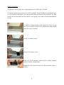
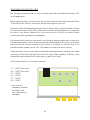
The VAC
Auricle
Triode Preamplifier
Operation & Maintenance Information
Valve Amplification Company
Manual issued 02/19/2004
CAUTION
DO NOT REMOVE THE COVER UNLESS THE UNIT IS COMPLETELY UNPLUGGED - ALL
CONNECTIONS MUST BE REMOVED - THEN WAIT 15 MINUTES BEFORE REMOVING THE
COVER. DO NOT CONNECT OR OPERATE UNLESS THE COVER IS FULLY INSTALLED. LETHAL
VOLTAGES ARE PRESENT WITHIN THE CHASSIS. DO NOT OPERATE THE UNIT IF IT IS WET.
VACUUM TUBES BECOME HOT ENOUGH TO CAUSE SERIOUS BURNS. NEVER TOUCH A TUBE
WHEN THE UNIT IS ON. IT MAY TAKE SEVERAL MINUTES FOR THE TUBES TO COOL DOWN
AFTER THE UNIT IS SWITCHED OFF.
BE CERTAIN TO INSTALL THIS UNIT IN A SECURE LOCATION FROM WHICH IT CAN NOT FALL
OR TIP OVER.
1
VAC AURICLE PREAMPLIFIER
Features:
S
S
S
S
S
S
S
S
S
All triode vacuum tube audio circuitry
Passively equalized phono stage
Triple shielded C-core power transformer
Full tape loop
Mono switch for minimizing noise from vintage records
Remote control
No loop feedback
High input impedance, low output impedance
Regulated filament supply
CARE OF CHASSIS
VAC chassis are aluminum for superior electromagnetic performance. The chassis is finished
in a durable powder coat paint. Cleaning the unit with a damp cloth WHILE THE AMP IS
SWITCHED OFF AND UNPLUGGED should suffice. Do not get cleaning solutions onto or into
the tube sockets.
2
UNPACKING & ASSEMBLY
The Auricle Preamplifier is shipped with the vacuum tubes installed.
Should the need ever arise to replace the tubes, follow all of the safety directions
contained in the beginning of this manual.
INSTALLATION
1)
Provide adequate ventilation.
2)
Do not operate on carpet or any other surface that might block air flow.
3)
The chassis will become warm in normal use.
4)
Do not allow the chassis to touch any metal parts, such as the frame of an equipment
rack. This might create a parallel ground path that could degrade the sound of your
system.
5)
All connections are via single ended RCA jacks. Connect line level inputs (CD, Tuner,
Tape, etc.) to the appropriate RCA input jacks on the rear panel (L1, L2, L3, or Tape
Play). Note: with the exception of Phono all inputs are "line level". The Tape Out jacks
may be used to feed a signal to a tape or disc recorder.
6)
Connect phono cables from a MM phono cartridge to the inputs labeled "Phono".
Connect the ground wire(s) from the turntable(s) or phono cable(s) to the "Ground"
terminal provided on the rear panel.
7)
Connect the AC cable from the wall outlet to the preamplifier. Be sure to insert the
connector properly and fully.
8)
Operate only from the power supply voltage labeled on the rear panel (100, 120,
220, or 240 volts AC). For best performance, try to route the power cord away from
signal cables.
9)
Pay close attention to power quality, and be aware that different power cords can
alter the sound. The backlit meter shows variation in power line voltage as reflected
to the audio circuitry.
3
INPUTS (back panel)
Three pairs of RCA jacks accommodate unbalanced line level sources. These are labeled
"L1" through "L3".
One pair of RCA jacks accommodate the monitor return from a tape deck. If you do not
have a tape deck, these jacks can be used as an additional line level input.
One phono input is provided for MM or ‘highouput’ MC cartridges. The ground lead from
the turntable should be connected to the binding post located by these jacks.
OUTPUTS (back panel)
One pair of RCA jacks provide line level output to a tape recorder. The level of signal is not
adjusted by the volume control.
Two sets of RCA output jacks are provided as main outputs to power amplifiers; you may
use either, or both for biamplification.
4
OPERATION
Turn the "Volume" control fully counterclockwise.
Mute is automatically engaged when switching on the unit.
Allow the preamplifier to warm up for a minute before you un-mute the unit; failure to wait
can cause a transient to be sent through your power amplifier that might cause damage to
your loudspeakers.
As with all high fidelity products, the sound characteristic of the VAC changes somewhat
as it warms up. Best sound will be achieved after about 15 minutes of operation.
Any time that the Auricle Preamplifier has not been used for a few weeks the sound may
be different. This is also normal for high resolution audio equipment. Optimum sound
should return after a few hours of operation, preferably with an audio signal.
Note that although your VAC System has been run for 48 hours at the factory, it will
continue to "break in" for approximately 150 hours. Also be aware that many components
display the need for a new break in period after being transported in unheated cargo
aircraft.
5
FRONT PANEL CONTROLS
Although most of the front panel controls (Volume, Power, Mute) are self explanatory, VAC
has outfitted this unit with several advanced features which bear further description:
Mute:
Toggles between the "Mute" and "Operate" condition. When muted, the
indicator light is illuminated.
Power:
Turns the unit off and on.
Mono:
Causes the left & right channels to be electrically added. Generally, this will
reduce background noise and distortion when playing monophonic analogue
phonograph records.
Selector:
This switch selects between L1 through L3 and the PHONO input. Rotate
counterclockwise to move down through the inputs, clockwise to move up
through the inputs.
Note: The MM input provides 44 dB of gain, suitable for use with MM (moving
magnet) and many high-output MC (moving coil) cartridges.
Tape:
This switch selects between the signal coming from the main selector or the
signal connected to the “TAPE IN” jacks.
Volume:
Controls the main output level for all inputs.
Balance:
Alters the signal levels between the left & right channels. This may be used to
compensate for uneven room acoustics and speaker differences, or
imbalance in source components. May also be used to compensate for slight
variations in gain as tubes age.
6
REMOTE CONTROL
The remote control allows for wireless adjustment of MUTE and VOLUME.
The remote wand is powered by two "AAA" batteries. These should be of the alkaline type.
You will need to install them in the wand before using the remote. Since batteries can leak,
they should be removed from the wand if it is not going to be used for an extended period
of time.
To install or change batteries, first loosen the screw on the
back of the remote, or slide off the battery door (depending
upon the style of remote).
Loosen the battery cover.
Remove the battery cover.
Insert two AAA batteries, observing the polarity diagram
inside th battery compartment.
Reassemble the remote control by following these steps in
reverse.
7
REPLACEMENT OF LOW LEVEL TUBES
We strongly recommend that you use only tubes specifically selected and tested by VAC
for this application.
Before replacing tubes, all power must be turned off and all cables disconnected. Allow
15 minutes for the tubes to cool down before removing the top cover.
Install new tubes of the appropriate types firmly in their sockets, noting the location of holes
in the socket and pins of the tubes, taking care to make sure that pin pattern corresponds
to holes in tube socket. Replace the cover and secure it will all of the screws before
connecting and/or operating the preamplifier.
In the event that trouble is encountered, check all signal, speaker and power connections.
If the problem persists, follow all safety precautions stated earlier in this section, and check
that all tubes are correctly seated in their sockets. If possible, try another tube. If the
problem persists, please consult your VAC dealer or contact the factory directly.
Tubes are like the tires on a car; they will eventually need replacement. Murphy's Law states
that a tube will probably fail right at the start of a long holiday weekend. Therefore, many
audiophiles keep a spare tube of each type on hand, just in case!
VAC can test tubes for concerned customers.
V1 = 12AX7 low noise*
V2 = 12AX7 low noise*
V3 = 12AX7
V4 = 12AU7
V5 = 12AX7
V6 = 12AX7
V5
V6
V4
* low noise not
necessarily required,
but helpful with
low output phono
cartridges
8
V1
V2
V3
TIPS & ADVICE SECTION
A Word About Tubes in General
It is true that each brand of tube sounds different in a particular high resolution circuit. This
is because no two manufacturers make a tube type in quite the same way, and the central
tendencies of the performance parameters will differ slightly with each maker. To emphasize
the point, examine the plate structure of any two 6SN7 from different manufacturers will
probably find that they may not even the same shape and size. (Be careful here, as often
a tube is made by a firm other than indicated on its label. In the heyday of tubes it was
common to crossbrand between major labels, such as GE and RCA. Today many labels do
not manufacture their tubes at all, including Gold Aero and RAM.)
This sonic variability may at first seem a liability, but further thought will reveal that it is an
advantage, just like the ability to adjust VTA on a tone arm. The owner of a tube amplifier
can select those tubes which sound like the real thing in his/her specific system. Of course,
if the manufacturer you prefer is rare you may want to purchase a few spare tubes for the
future.
How long should tubes last? It has long been known in professional circles (and probably
now forgotten) that a tube such as the 12AX7 will display better performance
characteristics after two years of continual operation than when it was new. In normal use
it is not unusual for a low level tube to last 5 years or longer. Output tubes are another story,
as they are continually providing significant amounts of current. Here the sound is your best
guide. Certainly a tube should be replaced when its emission is significantly down or its
transconductance is substantially out of specification. In normal use, output tubes will last
at least 2 years and perhaps more than 5 years.
In the event of unusual noise in one channel on all sources, the likely culprit is the
12AU7 tube.
A loss of sound in one channel on all inputs probably is due to the V5 or V6 tube.
Swap V5 (left) with V6 (right); if the problem changes channels then you have
found the bad tube.
A loss of sound or unusal noise in one channel on phono may be due to V1 or V2.
Swap V1 (left) with V2 (right); you have found the bad tube if the problem changes
channels.
VAC can test tubes for concerned customers.
9
VAC AURICLE PREAMPLIFIER SPECIFICATIONS (typical)
Type:
Vacuum tube triode preamplifier with integral triple-shielded
power transformer, remote control for volume & mute (manual
only version available by special order), and passively
equalized MM phono input.
Line stage preamplifier:
Gain:
Maximum input signal:
Main output:
Tape output:
22 dB
Infinite (attenuation precedes line stage)
Inverting (you may reverse speaker connections if you wish to
compensate, or set you d/a converter to phase reversal)
Unity gain from selector, non-inverting
Phono stage preamplifier:
Gain:
Residual noise:
Overload:
Frequency response:
Notes:
40 dB (measured at tape output)
less than 3 mV at output (S/N ratio approx. 69 dB)
117 mV @ 1 kHz = 8 volts RMS output
460 mV @ 10 kHz
RIAA +/- .25 dB
Does not invert absolute phase.
Tube compliment:
5 x 12AX7
1 x 12AU7/6189A
Warranty:
Three years parts and labor, excluding tubes.
10
WARRANTY
Your equipment is warranted for a period of thirty (30) days from the date of purchase. In addition, if the
registration form is received by VAC along with a copy of your sales receipt from an authorized VAC dealer
within this thirty days, a service contract will be extended to cover your equipment for three (3) years (tubes
excepted). This warranty applies only to units sold in the United States of America through authorized VAC
dealers. It covers factory service and standard return shipping. For warranty information outside of the U.S.
contact the importer of VAC equipment for your country. Units sold outside of the U.S. should still be
registered with VAC. It is responsibility of the dealer and customer to determine suitability of this unit for a
given application.
Your questions and comments are always welcome. Contact:
Valve Amplification Company
1731 Northgate Boulevard
Sarasota, FL 34234
Telephone (941) 359-2066
[email protected]
Fax (941) 359-2057
_____________________________Detach and mail to the address above as soon as possible.____________________________
Auricle Preamplifier Registration Form
Name
________________________________________________________________________
Address
________________________________________________________________________
________________________________________________________________________
Telephone
_______/_______-_____________
e-mail __________________________________
Dealer name
________________________________ City ________________________________
Salesperson
___________________ Purchase date
____________ Serial Number ________________
How did you first learn of VAC products? ____________________________________________________
What other brands/models did you consider? _________________________________________________
_____________________________________________________________________________________
What made you decide on the VAC? _______________________________________________________
_____________________________________________________________________________________
What else would you like us to know? _______________________________________________________
_____________________________________________________________________________________
_____________________________________________________________________________________
Optional:
What magazines do you read regularly?________________________________________________________
What are your hobbies (besides filling in warranty cards)? _______________________________________
What are your favorite types of music? ______________________________________________________
_____________________________________________________________________________________
On what format? (CD, LP, DVD, SACD, MP3, etc.) ______________________________________________
11