1
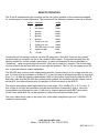
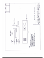
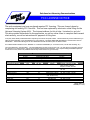
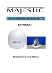
Solutions for Advancing Communications
M15- OWNER’S MANUAL
M15
Solid-State VHF Aeronautical Band
Radio Receiver/Transmitter
Mobile Transceiver
(118.000-136.975 MHz)
www.mentorradio.com
Phone: 216-265-2315 * Fax: 216-267-2915
M15-OM-11/11
INTRODUCTION
The Mentor Model M15 receives and transmits on up to six discrete channels in the vhf aviation
band between 118 and 137 MHz (25 KHz channel spacing). It operates from a 14 v dc supply, and is
intended for both vehicular and airborne application as well, and can also be used as a base
station. Its advanced design features and surface mount construction provide compactness, light
weight and high reliability. The only external components required are a suitable antenna with
coaxial cable, an aviation-type microphone and a 4- or 8-ohm speaker.
CIRCUIT DESCRIPTION
The receiver is a single-conversion superheterodyne with four varactor-tracked RF tuned circuits
and dual-gate MOSFET transistors in the RF amplifier and mixer stages. The local oscillator uses 3rd
overtone crystals, and is followed by a MOSFET frequency tripler stage. Receiver selectivity is
primarily determined by a six-pole 10.7 MHz crystal filter connected between the mixer and I.F.
amplifier. The latter consists of two cascode integrated circuit amplifier stages. Automatic gain
control is applied to the RF amplifier and the first I.F. amplifier stages.
A conventional diode detector is followed by a noise limiter, audio amplifier, squelch “gate” and
an integrated circuit audio power amplifier capable of delivering 4.5 watts of audio power into a 4ohm speaker. The transmitter oscillator also uses 3rd overtone crystals, followed by varactor
tracked MOSFET tripler and buffer amplifiers. Three untuned broadband stages boost the
transmitter carrier power to approximately 5 watts. Amplitude modulation is applied to the last
two stages, the "driver" and “final” amplifiers.
The transmitter signal passes through a 7-element Tchebychef low-pass harmonic filter which also
contains two PIN diodes functioning as a T-R switch. The transmitter modulator is separate from
the receiver audio amplifier, and includes an audio AGC amplifier that automatically adjusts for
variations in operator “microphone technique”. This circuit also prevents overmodulation.
The modulator power amplifier consists of an integrated circuit amplifier followed by
complementary bipolar transistors. This arrangement eliminates the need for an audio transformer,
resulting in less low frequency distortion while minimizing the size and weight of the radio.
The 25 watt RF transmitter power amplifier contains a single mosfet power transistor, operating
class AB, on a microstrip type printed circuit board. Two internal relays operate when the push-totalk microphone switch is pressed. These relays switch the amplifier’s input and output
connections, so that in the receive mode the signal from the antenna is passed directly back to the
M15’s receiver, while in the transmit mode the M15’s transmitter output is applied to the 25 watt
amplifier, whose output is in turn connected to the antenna. The power amplifier also contains a 5
section low-pass filter that greatly attenuates transmitter harmonics so that the system meets FCC
requirements for signal purity.
www.mentorradio.com
Phone: 216-265-2315 * Fax: 216-267-2915
M15-OM-11/11
INSTALLATION
The M15-25 can either simply rest on a shelf or desk, or it may be mounted in a 19 inch relay rack.
When rack mounted, rear support is not required. This unit does not contain a cooling fan, and
does not normally need one. However, when rack mounted there should be a minimum of 1-1/4
inch above and below the cabinet to allow air circulation. When the M15-25 is located on a desk or
shelf, do not place equipment, papers, magazines, etc. on top of it that would restrict its ability to
stay cool.
Note that during extended or frequent transmissions, the heat sinks on the rear panel will become
quite hot. While these have nylon covers for safety, under heavy use conditions operators should be
cautious about reaching behind the M15-25 and touching these parts. Power is applied via a
standard power inlet and IEC removable line cord. A rotary switch on the inlet allows selection of
either 115 or 230 volts ac. The fuse is (part of power inlet), a 4 amp. “international” type, can be
replaced by pulling out the fuse holder section (the cord must be removed first; and a light pry
from a screw driver may help in accessing the fuse). There is room for a spare fuse inside the
power inlet.
The antenna connector is type N. If the antenna coax does not mate with this type, adapters are
available from Mentor Radio or from many electronic distributors. Connections for remote
operation, when needed, are made via the 25 pin connector (type DB25) on the rear of the cabinet.
The antenna should be either a wideband type (118-137 MHz) or a narrow band type tuned to the
channel frequency. If a 3 or 6 dB gain antenna is used, communications range will be increased,
because gain antennas effectively increase both receiver sensitivity and transmitter power.
Low loss coaxial cable is recommended, especially if the cable length exceeds 30 feet (10 meters).
Plug an aircraft type or suitable pedestal type microphone into the microphone jack on the front
panel of the M15. Be sure the plug is pushed all the way into the jack. If remote operation is to be
used, refer to the section on this subject later in this manual.
www.mentorradio.com
Phone: 216-265-2315 * Fax: 216-267-2915
M15-OM-11/11
OPERATION
An on-off “rocker” type switch is in the center of the front panel. When lit, the built-in green LED
indicator shows that (1) the switch is in the on position (2) the equipment is receiving power from
the ac line (3) the internal dc power supply is operating. To operate, the M15 transceiver, which
projects through M15-25 the rack panel, must also be turned on by rotating its volume control
switch clockwise. If the squelch control knob is turned fully counterclockwise, receiver noise
should be heard in the speaker; the noise should get louder as the volume control is rotated more
clockwise. If there is to be no operator at the radio, and only remote operation is to be used, the
volume control may be set to minimum (fully CCW, without turning radio off).
It is not necessary to turn off the M15 if the M15-25 is turned off—the power to the M15 is removed
when the front panel rocker switch is turned off (green LED goes off). If the M15 has more than
one frequency, select the desired channel. Frequency selection may not be made remotely. If the
M15 contains crystals for only one channel, the frequency selector switch will have two positions
and either position will select the one available frequency.
If the background noise is annoying, it can be eliminated by rotating the squelch control clockwise.
Turn the squelch knob only as far as necessary to stop the noise—turning it farther than necessary
may prevent calls from distant aircraft from being heard in the receiver’s speaker. If it is
anticipated that it may be necessary to receive some very weak signals, use no squelch at all
(control fully CCW).
To transmit to an aircraft, fully depress the push-to-talk (PTT) switch on the microphone and speak
clearly and distinctly into the front of the microphone. Use a normal voice—not too soft nor too
loud (many readability problems are caused by poor “mike technique”). If the microphone is a
noise-canceling type it is absolutely necessary to hold the microphone very close to your mouth—
these microphones are very sensitive to this distance.
A red LED lamp on the M15 lights up when power is applied to the transmitter by pressing the PTT
switch. If this lamp stays on after the PTT button is released, a “stuck microphone” is indicated. If
you cannot release the PTT switch (button), turn off the radio or remove the microphone plug so
that your continuous transmission will not prevent others from using the radio channel.
In an emergency, you can transmit by plugging the microphone back in each time you want to
transmit. Although this equipment has been designed for congested radio signal environments,
very strong nearby transmissions on other channels may “bleed through” or desensitize the
receiver. This does not mean that the receiver is operating improperly. If interference is a
significant problem, contact Mentor Radio for assistance.
www.mentorradio.com
Phone: 216-265-2315 * Fax: 216-267-2915
M15-OM-11/11
REMOTE OPERATION
The 25 pin D-subminiature type connector on the rear panel contains all the connections needed
for various types of remote operation. The functions of the different connector pins are as follows:
PIN NO.
1
2
3
4
5
6
7
8
9
10
25
FUNCTION
COLOR
mic PTT
gray
mic audio
violet
ground
black
ground
black
ground
black
ground
black
4 ohm rcvr out
green
4 ohm rcvr out
green
500/600 ohm rcvr out green
squelch break
blue
+14 vdc
yellow
Connections to the mating connector can use #22 gauge wire. Note that there are four ground
terminals and two terminals for the 4 ohm receiver audio output. The ground terminals may be
used as needed for various remote connections; in some circumstances it may be desirable to
“double-up”, using two ground pins in parallel. (Each pin is rated for 1 ampere.) The 4 ohm audio
receiver outputs can be used with one or two external speakers. The +14 vdc can supply up to 500
ma. to operate external remote equipment.
The 500/600 ohm receiver audio output can be used for remote stations or for a tape recorder output. It’s level is factory adjusted to 0 dBm (0.77 v rms) but may be adjusted internally for any level
from -7 to +10 dBm by trimmer potentiometer R205 on the printed circuit board inside the M15-25.
Both the 4 ohm and the 500/600 ohm receiver audio outputs are unaffected by the volume control
on the M15, the latter affecting only the speaker on the front panel of the M15-25.
The remote microphone audio input should be in the range -10 to -16dBm (0.3 to 0.15 v rms). If
this voltage is too high the modulation may be distorted when transmitting—that is, the voice
transmissions may not sound as clear. If this occurs, trimmer potentiometer R207 (on printed
circuit board inside M15-25) can be adjusted to reduce the microphone audio level.
The colors listed above refer to the usual color codes when using Mentor part no. 1101368 6conductor remote cable.
www.mentorradio.com
Phone: 216-265-2315 * Fax: 216-267-2915
M15-OM-11/11
MAINTENANCE
No routine maintenance is necessary, other than to remove accumulated dust. If the equipment is
accidentally impacted or dropped operation should be fully checked and an internal inspection
made for loose or broken parts.
SERVICING AND REPAIR
Should the M15-25 require warranty servicing, return it to Mentor Radio with a description of the
problem. For out-of-warranty servicing, returning it to Mentor Radio is also recommended, but if
local servicing is preferred, service manuals can be obtained. Service should only be attempted by
technicians experienced with this type of equipment and who have available the appropriate test
equipment.
LICENSING
In the United States, all transmitters must be licensed by the Federal Communications Commission
(FCC). Application is filed on FCC form 406 for base stations. The M15-25 contains two different
equipments which must be listed on the application. Do not list the M15-25; instead list the M15
transceiver (FCC identification no. QQTM15) and the PA25 power amplifier (FCC identification no.
QQTPA25).
With each new M15, Mentor Radio, LLC. include instructions on how to complete form 406 online at
the FCC Internet web site (Dwg. 1100958). If the M15-25 is to be used on a channel in the
frequency range 128 to 132 Mhz (the “enroute” channels), the license application is handled
differently. Assignment of specific frequencies and the completion of form 406 is done by
Aeronautical Radio Incorporated (ARINC), a private organization which contracts to the FCC to
manage this part of the spectrum. Refer to Mentor Radio, LLC. dwg. 1101472, enclosed with new
units containing an enroute frequency.
www.mentorradio.com
Phone: 216-265-2315 * Fax: 216-267-2915
M15-OM-11/11
Solutions for Advancing Communications
FCC LICENSE NOTICE
The radio equipment you have purchased requires FCC licensing. This was formerly done by
completing and mailing FCC Form 406. This has been replaced by electronic online filing via the
Universal Licensing System (ULS). The Internet address for this is http://wireless.fcc.gov/uls/.
This site provides instructions for the application, as well as online forms to complete and transmit
electronically, as well as instructions for payment of filing fees.
In the past, Mentor Radio provided information required by Form 406 for its specific models. This information may still be needed when you
make the online application, and is provided below for your assistance. The Mentor Radio Model identification is not the same as the FCC
Identification. The first table below gives the FCC Identification and the transmitter power for Mentor models.
For all Mentor Radio transmitters enter “6K00A3E” for “emission and bandwidth (“0” is a numerical zero, not the letter following “N”).
You may be asked for a “Class of Station”. The second table below can help you select your Class. You must apply for a frequency that the
FCC permits for your selected Class. Some of the permissible frequencies are listed below. For a complete listing of available frequencies,
consult the FCC rules, Part 87.173 (available online at http://www./wireless.fcc.gov/rules.html).
Mentor Model
FCC Identification
Transmitter Output
M15
M15-25
MB
QQTM15
QQTM15 and QQTPA25
QQTMB
5 watts
25 watts
10 watts
Class of Station
FCC Code
MR Models
Typical Use
Frequencies Available
Aeronautical Advisory
FAU
MB, M15
Unicom
Aeronautical Multi-com
MFL
MB, M15
Air/Ground
Search & Rescue
Aviation Support
Aero. Utility Mobile
SAR
FAS
MOU
MB, M15
all
M15
No tower: 122.700, 122.800
Tower on field: 122.950
Heliport: 123.050, 123.075
Coordination 122.850, 122.900,
123.100
123.100
123.300, 123.500, 121.950
Aeronautical Enroute
Flight Test
Control Tower
FA
FAT
FAC
all
all
MB, M15-25
Flight Schools, Soaring
Airport vehicles Gnd.
Cont. & tower freqs
ARINC, Corp.
Manufacturers
numerous
128.825 to 132.000
123.200, 123.225
118.000-136.975
Mentor Radio, LLC
1100958 (rev 11-07)
LIMITED WARRANTY
Your Mentor Radio, LLC. equipment is warranted to the original consumer purchaser only, for one
full year, to be free from defects in materials and workmanship under normal use. This warranty
does not include damage to the product resulting from accident or misuse. This warranty will not
be effective unless you submit a Warranty Registration online at www.mentorradio.com .
If the equipment should become defective within the warranty period, we will elect to repair or
replace it, without charge, if returned, postage prepaid, to the address shown below. We are not
liable for defects or damages caused by the use of unauthorized replacement parts and/or service.
ALL IMPLIED WARRANTIES, INCLUDING THE IMPLIED WARRANTIES OF MERCHANTABILITY AND
FITTNESS FOR A PARTICULAR PURPOSE, ARE LIMITED IN DURATION TO ONE YEAR. Some states do
not allow limitations on how long an implied warranty lasts, so the above limitations may not apply
to you.
MENTOR RADIO, LLC., BECAUSE OF LACK OF CONTROL OVER THE CONDITIONS OF USE OF THIS
EQUIPMENT, IS NOT LIABLE FOR INCIDENTAL OR CONSEQUENTIAL DAMAGES. ANY RECOVERY
MAY NOT BE GREATER THAN THE PURCHASE PRICE PAID FOR THE EQUIPMENT. Some states do
not allow the exclusion or limitation of incidental or consequential damages, so the above may not
apply to you. This warranty gives you specific legal rights, and you may also have other rights
which vary from state to state.
www.mentorradio.com
Phone: 216-265-2315 * Fax: 216-267-2915
M15-OM-11/11