1
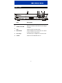
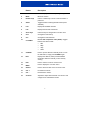
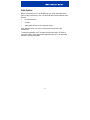
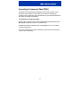
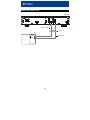
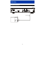
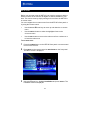
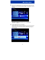
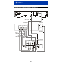
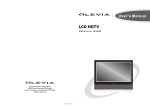
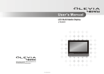
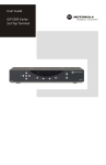
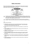
User Guide
HDT100
High Definition
Tuner
POWER
SIGNALLOSS
MENU
ENTER
POWER
EXIT
IMPORTANT SAFETY INSTRUCTIONS
1
2
3
4
5
6
7
8
9
10
11
Read instructions
All the safety and operating instructions should be read before the appliance is operated.
Retain instructions
The safety and operating instructions should be retained for future reference.
Heed warnings
All warnings on the appliance and in the operating instructions should be adhered to.
Follow instructions
All operating and use instructions should be followed.
Cleaning
Unplug this product from the wall outlet before cleaning. Do not use liquid cleaners or aerosol
cleaners. Use a damp cloth for cleaning.
Attachments
Do not use attachments not recommended as they may cause hazard.
Water and moisture
Do not use this equipment near water; for example, near a bathtub, wash bowl, kitchen sink, or
laundry-tub, in a wet basement, or near a swimming pool, and the like.
Accessories
Do not place this product on an unstable cart, stand, tripod, bracket, or table. The product may fall
causing serious injury and serious damage to the appliance. Use only with a cart, stand, tripod,
bracket, or table recommended by the manufacturer, or sold with the equipment. Any mounting of
the appliance should follow the manufacturer’s instructions, and should use a mounting accessory
recommended by the manufacturer.
Ventilation
Slots and openings in the cabinet are provided for ventilation and to ensure reliable operation of
the equipment and to protect it from overheating. The openings should never be blocked by
placing the product on a bed, sofa, rug, or similar surface. Equipment should never be placed near
or over a radiator or heat register, or in a built-in installation such as a bookcase or rack unless
proper ventilation is provided.
Power sources
This product should be operated only from the type of power sources indicated on the marking
label. If you are not sure of the type of power supplied to your home, consult your local power
company. For equipment intended to operate from battery power, or other sources, refer to the
operating instructions.
Ground or polarization
This equipment may be equipped with a polarized alternating-current line plug (a plug having one
blade wider than the other). This plug will fit into the power outlet only one way. This is a safety
feature. If you are unable to insert the plug fully into the outlet, try reversing the plug. If the plug
should still fail to fit, contact your electrician to replace your obsolete outlet. Do not defeat the
safety purpose of the polarized plug.
This equipment may be equipped with a 3-wire grounding-type plug, a plug having a third
(grounding) pin. This pin will only fit into a grounding-type power outlet. This is a safety feature. If
you are unable to insert the plug into the outlet, contact your electrician to replace your obsolete
outlet. Do not defeat the safety purpose of the grounding-type plug.
12
Power cord protection
Power supply cords should be routed so that they are not likely to be walked on or pinched by
items placed upon or against them, paying particular attention to cords at plugs, convenience
receptacles, and the point where they exit from the appliance
IMPORTANT SAFETY INSTRUCTIONS
13
14
15
16
17
18
19
Outdoor Antenna Grounding
If an outside antenna or cable system is connected to the equipment, be sure the antenna or cable
system is grounded as to provide some protection against voltage surges and built-up static
charges. Article 810 of the National Electrical Code, ANSI/NFPA 70, provides information with
regard to proper grounding of the mast and supporting structure, grounding of the lead-in wire to
an antenna discharge unit, size of grounding conductors, location of antenna-discharge unit,
connection to grounding electrodes, and requirements for the grounding electrode.
Lightning
For added protection for this equipment during a lightning storm, or when it is left unattended and
unused for long periods of time, unplug it from the wall outlet and disconnect the antenna or cable
system. This will prevent damage to the video product due to lightning and power line surges.
Power lines
An outside antenna system should not be located in the vicinity of overhead power lines or where it
can fall into such power lines or circuits. When installing an outside antenna system, extreme care
should be taken to keep from touching such power lines or circuits, as contact with them may be
fatal.
Overloading
Do not overload wall outlets and extension cords as this can result in a risk of fire or electrical
shock.
Object and liquid entry
Never push objects of any kind into this equipment through openings, as they may touch
dangerous voltage points or short-out parts that could result in a fire or electrical shock. Never spill
liquid of any kind on the product.
Servicing
Do not attempt to service this equipment yourself, as opening or removing covers may expose you
to dangerous voltage or other hazards, refer all servicing to qualified service personnel.
Damage requiring service
Unplug this equipment from the wall outlet and refer servicing to qualified service personnel under
the following conditions:
~= When the power supply cord or plug is damaged.
Ä= If the equipment has been exposed to rain or water.
Å= If liquid has been spilled, or objects have fallen into the equipment.
Ç= If the equipment does not operate normally by following the operating instructions. Adjust only
those controls that are covered by the operating instructions, as an improper adjustment of
other controls may result in damage and will often require extensive work by a qualified
technician to restore the equipment to its normal operation.
É= If the equipment has been dropped or cabinet has been damaged.
Ñ= When the equipment exhibits a distinct change in performance, indicating a need for service.
20
21
Replacement parts
When replacement parts are required, be sure the service technician has used replacement parts
specified by the manufacturer or have the same characteristics as the original part. Unauthorized
substitutions may result in fire, electric shock, or other hazards.
Safety check
Upon completion of any service or repairs to this video product, ask the service technician to
perform safety checks to determine that the product is in proper operational condition.
IMPORTANT SAFETY INSTRUCTIONS
22
Battery usage
Notwithstanding any information provided by Motorola in this manual regarding the use of
batteries, the end user assumes all responsibility and liability to use and dispose of batteries in
accordance with all applicable laws, rules and regulations. Motorola will not be liable to anyone for
the end user's failure to use and/or dispose of batteries in the proper manner and in accordance
with such laws, rules and regulations, or for any defect contained in batteries which may cause
injury damage to persons or property.
Regulatory Information
Federal Communications Commission Radio and Television Interface Statement for a Class ‘B’
Device
This equipment has been tested and found to comply with the limits for a Class B digital device,
pursuant to part 15 of the FCC Rules. These limits are designed to provide reasonable protection
against harmful interference in the residential installation. This equipment generates, uses and can
radiate radio frequency energy and, if not installed and used in accordance with the instructions, may
cause harmful interference to radio communications. However, there is no guarantee that interference
will not occur in a particular installation.
If the equipment does cause harmful interference to radio or television reception, which can be
determined by turning the equipment off and on, the user is encouraged to try to correct the interference
by one of the following measures:
•
Increase the separation between the equipment and the affected receiver
•
Connect the equipment on a circuit different from the one the receiver is on
•
Ensure that the cover plate for the security card is secured and tight
Changes or modification not expressly approved by the party responsible for compliance could void the
user’s authority to operate the equipment.
Declaration of Conformity
According to 47 CFR, Parts 2 and 15 for Class B Personal Computers and Peripherals; and/or CPU
Boards and Power Supplies used with Class B Personal Computers, Motorola, Inc., 6450 Sequence
Drive, San Diego, CA 92121, 1-800-225-9446, declares under sole responsibility that the product
identifies with 47 CFR Part 2 and 15 of the FCC Rules as a Class B digital device. Each product
marketed is identical to the representative unit tested and found to be compliant with the standards.
Records maintained continue to reflect the equipment being produced can be expected to be within the
variation accepted, due to quantity production and testing on a statistical basis as required by 47 CFR
2.909. Operation is subject to the following condition: This device must accept any interference received,
including interference that may cause undesired operation. The above named party is responsible for
ensuring that the equipment complies with the standards of 47 CFR, Paragraphs 15.101 to 15.109. The
Class B digital apparatus meets all requirements of the Canadian Interface Causing Equipment
Regulations.
Canadian Compliance
This Class B digital apparatus complies with Canadian ICES-003. Cet appareil numérique de la classe
B est conforme à la norme NMB-003 du Canada.
Contact Us
For technical support of your Receiver, call Motorola Support at 1-866-668-2271 or 1-866-MOT-BCS1.
For Motorola consumer cable products, education, and support:
http://www.motorola.com/broadband
___________________________________________________________________________________
Copyright © 2003 Motorola, Inc.
All rights reserved. No part of this publication may be reproduced in any form or by any means or used
to make any derivative work (such as translation, transformation or adaptation) without written
permission from Motorola, Inc.
Motorola reserves the right to revise this publication and to make changes in content from time to time
without obligation on the part of Motorola to provide notification of such revision or change. Motorola
provides this guide without warranty of any kind, either implied or expressed, including but not limited to,
the implied warranties of merchantability and fitness for a particular purpose. Motorola may make
improvements or changes in the product(s) described in this manual at any time.
MOTOROLA and the Stylized M Logo are registered in the US Patent & Trademark Office. Dolby is a
registered trademark of Dolby Laboratories Licensing Corporation. All other product or service names
are the property of their respective owners.
© Motorola, Inc. 2003
CONTENTS
OVERVIEW ............................................................................................... 3
HDT100 Components ......................................................................... 4
What You’ll Need to Get Started ........................................................ 4
FRONT PANEL......................................................................................... 5
REMOTE CONTROL ................................................................................ 6
INSTALLING THE HDT100 ...................................................................... 8
Video Options ..................................................................................... 9
Connecting for Component Video (YPbPr) ...................................... 11
Connecting for S-Video or Composite Video.................................... 13
Audio Connections............................................................................ 15
Connecting the Antenna and Power Cord ........................................ 17
AUTO SCAN ........................................................................................... 18
OPERATION ........................................................................................... 21
Using the i-Banner to View Program Information ............................. 21
Using Closed Captions ..................................................................... 23
ON-SCREEN MENU ............................................................................... 24
Selecting Favorite Channels............................................................. 25
Setting Parental Controls.................................................................. 26
Changing Your Password ................................................................. 28
Setting Up the HDT100’s Clock for Your Time Zone........................ 29
Adding a Channel ............................................................................. 30
Customizing the On-Screen Menu and i-Banner.............................. 31
1
CONNECTING OTHER DEVICES TO THE HDT100............................. 32
Connecting your VCR and Standard TV........................................... 33
Connecting your A/V Receiver, VCR and High Definition TV .......... 35
Connecting your A/V Receiver, VCR and Standard TV ................... 37
FINDING DIGITAL TV STATIONS IN YOUR AREA.............................. 38
REMOTE CONTROL IR INFORMATION............................................... 39
HDT100 ON-SCREEN MENU STRUCTURE ......................................... 40
TROUBLESHOOTING............................................................................ 41
2
OVERVIEW
The Motorola HDT100 gives you access to free over-the-air digital
television signals for your HDTV-ready home entertainment system or
HDTV-capable monitor. If you are located in one of the local markets
served by off-air digital broadcasts, you can start receiving High
Definition signals with your HDT100 and an antenna*.
The HDT100 offers:
•
Conversion of all formats of digital TV signals to match your TV
•
Support for all 18 ATSC digital broadcast formats
•
Full bands VHF/UHF
•
Storage capacity of up to 1,500 digital channels
•
Three different video connections: Component (YPbPr), S-Video
and Composite
•
Full movie quality sound through Dolby Digital decode or
pass-through for connection to your home theater system
•
An easy to use on-screen menu that allows you to see program
information and TV schedules, switch between favorite channels
and a host of other convenient functions
•
Parental control features
•
Closed captioning
™
*A separate antenna with a coaxial cable (not included) is required to
receive over-the-air digital TV signals.
3
HDT100 Components
The following items are packed with your HDT100:
•
Remote control with batteries
•
Audio (Left/Right) cables
•
Component (YPbPr) cables
•
HDT100 User Guide
•
HDT100 Quick Start Guide
What You’ll Need to Get Started
To set up your HDT100, you’ll need:
•
A TV antenna, either outdoor or indoor
•
A coaxial cable to attach the antenna to your HDT100
4
FRONT PANEL
3
2
4
5
6
1
POWER
SIGNAL LOSS
MENU
ENTER
POWER
EX IT
Item
Description
1
POWER LED
Lights to indicate the HDT100 is powered.
2
SIGNAL LOSS LED
Lights to indicate the HDT100 has lost the digital
TV signal.
3
EXIT
Press to exit the on-screen menu.
4
MENU/ENTER
Press to display the on-screen menu or to select
an item on the on-screen menu.
5
Arrow keys
Use these keys to navigate the on-screen menu.
6
POWER
Press to turn the HDT100 off or on.
5
REMOTE CONTROL
1
2
11
3
4
12
5
13
6
14
7
15
8
16
9
17
10
18
6
Button
Description
1
CC
Press to display the closed captioning settings.
2
MUTE
Mutes the volume.
3
Number keys
Use the number keys to enter a channel number or
password.
4
AUDIO
Toggles between multi-lingual audio tracks (when
available).
5
LIST
Displays all available channels.
6
FAV
Displays the Favorite Channel list.
7
Arrow keys
Use these keys to navigate the on-screen menu.
8
CH +
Changes the channels up.
9
CH -
Changes the channels down.
10
V. FORMAT
For use with component video (YPbPr). Toggles
between the video formats:
•
480i
•
480p
•
720p
•
1080i
11
STANDBY
Press to put the HDT100 in standby mode. To turn
the HDT100 on, simply press STANDBY again.
12
INFO
Displays the i-Banner, which provides detailed
information about the channel you are currently
viewing.
13
EXIT
Press to exit the current on-screen menu.
14
MENU
Press to display the on-screen menu.
15
SELECT
Press to select an item on the on-screen menu.
16
VOL +
Increases the volume.
17
VOL -
Decreases the volume.
18
A. RATIO
Adjusts the aspect ration between 16:9 and 4:3 and
changes zoom and letterbox modes.
7
INSTALLING THE HDT100
The steps in this section show you how to quickly and easily connect
your HDT100 to your TV:
•
Video connections
•
Audio connections
•
Antenna and power
Before you hook up your HDT100, please review the following:
•
Disconnect power from the HDT100 before connecting or changing
cable connections.
•
Do not place anything on top of the HDT100, especially other
home entertainment components.
If you wish to connect your HDT100 to your VCR or home theater
receiver, see the additional connection diagrams at the back of this
manual.
8
Video Options
Before connecting your TV to the HDT100, you must determine which
type of video connection to use. The HDT100 offers three different video
options:
•
Component video
•
S-Video
•
Video (also referred to as composite video)
High definition video can only be viewed with component video
connections.
To determine whether your TV features component video, S-Video or
composite video, check the manual supplied with your TV to determine
the best connection available.
9
INSTALLING THE HDT100
HDT100
Manufactured under license from Dolby Laboratories.
D olby and the double -D symbol are trademarks of Dolby Laboratories.
100~240V AC
50~60 Hz , 2A
RS -232
OPTICAL
Y
VID EO
Pb
L
Pr
R
S-VID
EO
Component video cable
TV
Component
Video Input
Y
Pb
Pr
10
AN T. IN
Connecting for Component Video (YPbPr)
Component video provides the highest level of picture quality. If your
television has component video inputs (Y, Pb and Pr connectors),
connect to the component video connections on your HDT100 instead of
the Video or S-Video connections.
To connect for component video:
Connect the component video cable supplied with the HDT100 to the Y,
Pb, and Pr connectors on your TV and HDT100.
If component video connections are not available on your TV, use the
S-Video connections.
Once you complete your video connections, proceed to the instructions
for the audio connections.
11
INSTALLING THE HDT100
HDT100
Manufactured under license from Dolby Laboratories.
D olby and the double -D symbol are trademarks of Dolby Laboratories.
Y
100~240V AC
50~60 Hz , 2A
RS -232
VIDEO
Pb
L
Pr
R
OPTICAL
S-VIDEO
AN T. IN
S-Video cable
Either / or
TV
Video cable
INPUT
S-VIDEO
VIDEO
12
Connecting for S-Video or Composite Video
High definition video can only be viewed with component video
connections. S-Video and composite video do not offer high definition
video.
To connect for S-Video:
Connect an S-Video cable (not supplied) to the S-VIDEO connector on
your HDT100 and the INPUT S-VIDEO connector your TV.
If your TV does not offer S-Video, use the composite (VIDEO)
connections.
To connect for composite video:
Connect a video cable (not supplied) to the VIDEO connector on your
HDT100 and the INPUT VIDEO connector on your TV.
Now proceed to the next step--hooking up your audio connections.
13
INSTALLING THE HDT100
HDT100
Manufactured under license from Dolby Laboratories.
D olby and the double -D symbol are trademarks of Dolby Laboratories.
Y
100~240V AC
50~60 Hz , 2A
RS -232
OPTICAL
VID EO
Pb
L
Pr
R
S-VID
EO
Audio cable
TV
INPUT
AUDIO LEFT
AUDIO RIGHT
14
AN T. IN
Audio Connections
To hook up your audio connections:
Connect the stereo audio cable supplied with your HDT100 to the L and
R connectors on the HDT100 and the INPUT AUDIO LEFT and RIGHT
connectors on your TV.
Now proceed to the next step—connecting your antenna and power
cord.
15
INSTALLING THE HDT100
HDT100
Manufactured under license from D olby Laboratories.
Dolby and the double -D symbol are trademarks of Dolby Laboratories.
Y
100~240V AC
50~60 Hz , 2A
RS -232
OPTICAL
To
wall outlet
VIDEO
Pb
L
Pr
R
S-VID
EO
ANT. IN
To
antenna
16
Connecting the Antenna and Power Cord
You can use an outdoor or indoor antenna to receive over-the-air high
definition TV signals:
1
Connect your antenna’s coaxial cable to the ANT IN connector on
your HDT100.
2
Plug the power cord supplied with your HDT100 into the HDT100’s
power connector and then plug the cord into a wall outlet.
Now that you’ve completed hooking up your HDT100, you’re ready to
program your HDT100 with over-the-air digital TV stations. Proceed to
“Auto Scan” on the following page for instructions.
17
AUTO SCAN
Before you can start using the HDT100, you need to program it with the
station numbers of the over-the-air digital TV stations available in your
area. This can be done by simply running auto scan from the HDT100’s
on-screen menu.
You can navigate the on-screen menu from the HDT100’s front panel or
by using the remote control:
•
Use the ! and "arrow keys to move up and down the on-screen
menu
•
Use the SELECT button to select the highlighted item on the
on-screen menu
•
Use the EXIT button to return to the main menu from a submenu or
to leave the main menu
To run auto scan:
1
Press the POWER button on the HDT100 front panel or remote control
to turn on the receiver.
2
Press MENU on the remote control or MENU/ENTER on the front panel.
The Menu screen is displayed:
3
Using the "arrow key, highlight Installation and press SELECT. The
Password window is displayed.
18
4
Enter your four-digit password. If you have not yet created your own
password, enter the default password: 0000. The Installation menu is
displayed:
If you wish to change your password, see “Changing Your
Password” on page 28.
5
Highlight Auto Scan and press SELECT.
The HDT100 starts scanning from Channels 2 to 69. The entire scan
will take about four minutes. An indicator is displayed showing the
scan’s progress:
19
As each digital TV signal is scanned, you’ll see the signal’s channel
number and program name displayed on the Program List:
The auto scan will end on channel 69.
6
Press EXIT to return to the main menu.
7
Press EXIT again to exit the main menu and start enjoying digital TV
programs!
If the picture displayed on your TV is too small, use the A. RATIO
button on your remote control to change the picture size.
20
OPERATION
Once your HDT100 is hooked up to your antenna and TV and you’ve
added your TV channels, you can enjoy digital over-the-air TV programs.
Simply use the remote control supplied with your HDT100 to change
channels, view program information, and navigate the on-screen menus.
If you encounter any problems while operating your HDT100, please
refer to the Troubleshooting guide at the back of this manual.
Using the i-Banner to View Program Information
If you want to learn more about the channel you are watching, press INFO
on your remote control and the HDT100 i (Information)-Banner will be
displayed:
The i-Banner will not display if you are viewing the HDT100’s on-screen
menu. Exit the on-screen menu and then press INFO on your remote
control to view the i-Banner.
21
The i-Banner provides the following information about the channel you
are viewing:
•
Current Channel Number
•
Network Name
•
Program Name
•
Audio System
•
Current Local Time (as provided by the local TV network)
•
Date and Month
•
Signal Level and Signal Quality
To view extended program information about the channel you are
currently viewing, press INFO again (with the i-Banner still displayed on
your screen). A program listing is displayed for the current channel.
To view more information on a specific program in the program listing,
use the # and $ keys on your remote control to highlight the program
and press SELECT.
To exit any of the windows, press EXIT on your remote control.
The i-Banner will disappear from your screen after a set period of time.
To change your i-Banner settings, see “Configuring your i-Banner
Settings” in the On-Screen Menu section.
22
Using Closed Captions
To turn on closed captions:
1
Press CC on your remote control to display the Closed Captions
Settings.
2
Using the ! and " keys, highlight CC1 to select primary closed
captions (in English) or highlight CC2 to select secondary closed
captions (in an alternate language).
3
Press SELECT.
Some programs offer advanced closed captions. Advanced programs will
list different languages under Closed Captions Settings. Simply use the
! and " keys to highlight the desired language and then press SELECT.
If a language is listed in the Closed Captions Settings with –E after it, this
closed caption service will offer more expanded descriptions than regular
closed captions. If a language is listed with –W after it, the closed caption
service has been designed specifically for wide-screen TVs (16:9).
Some programs may not transmit closed captions.
23
ON-SCREEN MENU
You can use the HDT100’s on-screen menu to:
•
Select favorite channels
•
Set up parental controls
•
Set up the HDT100’s clock
•
Add a channel
•
Customize the on-screen menu and i-Banner
Instructions for completing the tasks listed above, as well other
on-screen menu functions, are included in this section.
You can navigate the on-screen menu from the HDT100’s front panel or
by using the remote control:
•
Use the ! and "arrow keys to move up and down the on-screen
menu
•
Use the SELECT button to select the highlighted item on the
on-screen menu
•
Use the EXIT button to return to the main menu from a submenu or
to leave the main menu
24
Selecting Favorite Channels
If there are certain channels you wish to access quickly, you can set
them as favorites in the HDT100 on-screen menu. Favorite channels can
be quickly accessed from the Favorite Channel List by pressing FAV on
the remote control.
To set your favorites:
1
Press MENU on the remote control or MENU/ENTER on the front panel.
The Menu screen is displayed.
2
Highlight Edit Channel and press SELECT. The Password window is
displayed.
3
Enter your four-digit password. If you have not yet created your own
password, enter the default password: 0000. The Edit Channel
window is displayed:
If you wish to change your password, see “Changing Your
Password” on page 28.
4
Use the ! and " keys to select the channel you wish to set as a
favorite.
5
Use the $ key to highlight the FAV column for that channel and
press SELECT. The “favorite” icon appears in the column.
6
Press EXIT twice to exit the on-screen menu.
25
Setting Parental Controls
The HDT100 offers two options for parental controls:
•
V-Chip
•
Channel Lock
You can use the V-chip technology to block certain types of
programming from being viewed. The V-chip settings are based on the
MPAA and TV ratings systems. Once you set the rating limit in the
V-Chip Setup menu, no programming beyond that rating limit can be
viewed.
To set up your V-chip settings:
1
Press MENU on the remote control or MENU/ENTER on the front panel.
The Menu screen is displayed.
2
Highlight Installation and press SELECT. The Password window is
displayed.
3
Enter your four-digit password. If you have not yet created your own
password, enter the default password: 0000. The Installation menu is
displayed.
If you wish to change your password, see “Changing Your
Password” on page 28.
4
Highlight V-Chip Setup and press SELECT. The V-Chip Setup
window is displayed.
5
Use the !"# $ keys to highlight the desired rating limit(s) and then
press SELECT.
6
When finished, press EXIT twice to exit the on-screen menu.
26
You can lock a specific channel or channels so they cannot be viewed
without entering a password.
To lock a channel:
1
Press MENU on the remote control or MENU/ENTER on the front panel.
The Menu screen is displayed.
2
Highlight Edit Channel and press SELECT. The Password window is
displayed.
3
Enter your four-digit password. If you have not yet created your own
password, enter the default password: 0000. The Edit Channel
window is displayed:
If you wish to change your password, see “Changing Your
Password” on page 28.
4
Use the ! and " keys to select the channel you wish to lock.
5
Use the $ key to highlight the Lock column for that channel and
press SELECT. The lock icon appears in the column.
6
Press EXIT twice to exit the on-screen menu.
27
Changing Your Password
The default password that is already configured in the HDT100 is 0000.
To change the password:
1
Press MENU on the remote control or MENU/ENTER on the front panel.
The Menu screen is displayed.
2
Highlight System and press SELECT. The System menu is displayed.
3
Highlight Password and press SELECT.
4
Enter the current password or default password.
5
Using the number keys on the remote control, type in your four-digit
password.
6
Re-enter your password to confirm it.
7
Press EXIT twice to exit the on-screen menu.
28
Setting Up the HDT100’s Clock for Your Time Zone
To change the time zone for the HDT100’s clock:
1
Press MENU on the remote control or MENU/ENTER on the front panel.
The Menu screen is displayed.
2
Highlight Installation and press SELECT. The Password window is
displayed.
3
Enter your four-digit password. If you have not yet created your own
password, enter the default password: 0000. The Installation menu is
displayed.
If you wish to change your password, see “Changing Your
Password” on page 28.
4
Highlight Clock Setup and press SELECT. The Local Time window is
displayed:
5
Use the # and $ keys to change the time zone. When you are
finished, Press EXIT twice to exit the on-screen menu.
29
Adding a Channel
If you wish to add a specific channel to your program list or you have
made minor adjustments to your antenna, follow these steps for adding a
single channel:
1
Press MENU on the remote control or MENU/ENTER on the front panel.
The Menu screen is displayed.
2
Highlight Installation and press SELECT. The Password window is
displayed.
3
Enter your four-digit password. If you have not yet created your own
password, enter the default password: 0000. The Installation menu is
displayed.
If you wish to change your password, see “Changing Your
Password” on page 28.
4
Highlight Manual Scan and press SELECT. The Manual Scan window
is displayed:
5
Use the number keys on the remote control to enter the channel
number. Press the " key and then press SELECT to start the scan.
If the channel is successfully added, the “Get Channel Success”
message is displayed.
30
6
Press EXIT twice to exit the on-screen menu.
If the HDT100 is unable to lock on the channel’s signal, a “Time out
error” message is displayed. Adjust the antenna’s position and try adding
the channel again.
Customizing the On-Screen Menu and i-Banner
To change the transparency of the on-screen menu:
1
Press MENU on the remote control or MENU/ENTER on the front panel.
The Menu screen is displayed.
2
Highlight Menu Setup and press SELECT. The Menu Setup menu is
displayed.
3
Highlight Transparency and press SELECT. The transparency
indicator bar is displayed.
4
Use the # and $ keys to change the transparency of the on-screen
menu.
5
When finished, press EXIT twice to exit the on-screen menu.
To configure how your i-Banner is displayed:
1
Press MENU on the remote control or MENU/ENTER on the front panel.
The Menu screen is displayed.
2
Highlight Menu Setup and press SELECT. The Menu Setup menu is
displayed.
3
Highlight i-Banner Setup and press SELECT. The i-Banner Setup
window is displayed.
4
Use the ! and " keys to select an item. Press the # and $ keys to
change a setting:
5
Fading Mode
Fade Out or No Fade
Display Time
1 – 10 seconds
Time Format
AM/PM or 24 hr
When finished, press EXIT twice to exit the on-screen menu.
31
CONNECTING OTHER DEVICES TO THE HDT100
HDT100
Manufactured under license from Dolby Laboratories.
Dolby and the double -D symbol are trademarks of Dolby Laboratories.
Y
100~240V AC
50~60 Hz , 2A
RS -232
OPTICAL
VIDEO
Pb
L
Pr
R
S-VIDEO
-
ANT. IN
Audio cable
Video cable
VCR
TV
INPUT
INPUT
AUDIO
OUTPUT
VIDEO
AUDIO
VIDEO
VIDEO
AUDIO LEFT
R
L
R
L
AUDIO RIGHT
32
Connecting your VCR and Standard TV
1
Connect the stereo audio cable supplied with the HDT100 to the L
and R connectors on the HDT100 and the INPUT AUDIO R and L
connectors on the VCR.
2
Connect a video cable to the VIDEO connector on the HDT100 and
the INPUT VIDEO connector on the VCR.
If your equipment supports it, S-Video connections may be used in
place of the standard composite video connections. In most cases,
S-Video offers a higher level of standard definition video quality than
composite video.
3
Connect a stereo audio cable to the OUTPUT AUDIO R and L
connectors on the VCR and the INPUT AUDIO RIGHT and LEFT
connectors on the TV.
4
Connect a video cable to the OUTPUT VIDEO connector on the VCR
and the INPUT VIDEO connector on the stereo TV.
33
CONNECTING OTHER DEVICES TO THE HDT100
HDT100
Manufactured under license from Dolby Laboratories.
Dolby and the double -D symbol are trademarks of Dolby Laboratories.
VIDEO
Y
100~240V AC
50~60 Hz , 2A
Pb
L
Pr
R
OPTICAL
RS -232
S-VID
EO
AN T. IN
Optical digital
audio cable
Video cable
Stereo TV
Stereo VCR
INPUT
COMPONENT
VIDEO INPUT
INPUT
AUDIO
R
L
VIDEO
S-VIDEO
OUTPUT
AUDIO
R
VIDEO
L
Y
VIDEO
Pb
AUDIO LEFT
Pr
AUDIO RIGHT
Video cable
Audio
cable
Video
cable
A/V receiver
AUDIO
R
L
VIDEO
VIDEO S-VIDEO
DVD
OPTICAL
VIDEO 2
TV/MONITOR
OUTPUT
IN
VCR
OUT
34
SPEAKER
CONNECTORS
Connecting your A/V Receiver, VCR and High Definition TV
1
Connect the component video cable supplied with the HDT100 to the
Y, Pb, and Pr connectors on your TV and HDT100.
2
Connect an optical digital audio cable to the OPTICAL connector on
the HDT100 and the OPTICAL input connector on the A/V receiver.
3
Connect a video cable to the VIDEO connector on the HDT100 and
the CABLE/TV VIDEO connector on the A/V receiver.
If your equipment supports it, S-Video connections may be used in
place of the standard composite video connections. In most cases,
S-Video offers a higher level of standard definition video quality than
composite video.
4
Connect a stereo audio cable to the VCR AUDIO OUT R and L
connectors on the A/V receiver and the INPUT AUDIO R and L
connectors on the stereo VCR.
When using the Digital Audio output (OPTICAL or SPDIF), the left / right
baseband audio connections to the A/V receiver are not needed.
5
Connect a stereo audio cable to the OUTPUT AUDIO OUT R and L
connectors on the stereo VCR and the VCR AUDIO IN R and L
connectors on the A/V receiver.
6
Connect a video cable to the INPUT VIDEO connector on the stereo
VCR and the VIDEO VCR OUT connector on the A/V receiver.
7
Connect a video cable to the OUTPUT VIDEO connector on the stereo
VCR and the VIDEO VCR IN connector on the A/V receiver.
8
Connect a video cable to the INPUT VIDEO connector on the stereo TV
and the TV/MONITOR OUTPUT VIDEO connector on the A/V receiver.
To switch between viewing input from your VCR and input from your
HDT100, change your TV’s video inputs.
35
CONNECTING OTHER DEVICES TO THE HDT100
HDT100
Manufactured under license from Dolby Laboratories.
Dolby and the double -D symbol are trademarks of D olby Laboratories.
Y
100~240V AC
50~60 Hz , 2A
OPTICAL
RS -232
VIDEO
Pb
L
Pr
R
S-VIDEO
-
ANT. I N
Optical digital
audio cable
Video cable
Stereo TV
Stereo VCR
INPUT
INPUT
AUDIO
VIDEO
S-VIDEO
OUTPUT
AUDIO
VIDEO
VIDEO
AUDIO LEFT
R
L
R
L
AUDIO RIGHT
Video cable
Audio
cable
Video
cable
A/V receiver
AUDIO
R
L
VIDEO
VIDEO S-VIDEO
DVD
OPTICAL
VIDEO 2
TV/MONITOR
OUTPUT
IN
VCR
OUT
36
SPEAKER
CONNECTORS
Connecting your A/V Receiver, VCR and Standard TV
1
Connect an optical digital audio cable to the OPTICAL connector on
the HDT100 and the OPTICAL input connector on the A/V receiver.
2
Connect a video cable to the VIDEO connector on the HDT100 and
the CABLE/TV VIDEO connector on the A/V receiver.
If your equipment supports it, S-Video connections may be used in
place of the standard composite video connections. In most cases,
S-Video offers a higher level of standard definition video quality than
composite video.
3
Connect a stereo audio cable to the VCR AUDIO OUT R and L
connectors on the A/V receiver and the INPUT AUDIO R and L
connectors on the stereo VCR.
4
Connect a stereo audio cable to the OUTPUT AUDIO OUT R and L
connectors on the stereo VCR and the VCR AUDIO IN R and L
connectors on the A/V receiver.
5
Connect a video cable to the INPUT VIDEO connector on the stereo
VCR and the VIDEO VCR OUT connector on the A/V receiver.
6
Connect a video cable to the OUTPUT VIDEO connector on the stereo
VCR and the VIDEO VCR IN connector on the A/V receiver.
7
Connect a video cable to the INPUT VIDEO connector on the stereo TV
and the TV/MONITOR OUTPUT VIDEO connector on the A/V receiver.
When using the Digital Audio output (OPTICAL or SPDIF), the left / right
baseband audio connections to the A/V receiver are not needed.
37
FINDING DIGITAL TV STATIONS IN YOUR AREA
To find the digital TV stations available in your area:
1
Log on to the following website:
http://www.antennaweb.org/
2
Select Choose An Antenna.
3
Enter your address and find the DTV stations airing the EDTV/HDTV
signal you can receive.
You can also use the AntennaWeb website to get information on
choosing the correct antenna type and instructions for positioning the
antenna for the DTV station you want to watch.
NAB (National Association of Broadcasters) has updates on the local
DTV stations in operation at:
http://www.nab.org/Newsroom/Issues/digitaltv/DTVstations.asp
38
REMOTE CONTROL IR INFORMATION
The HDT100 uses the RC5 IR protocol with the following codes:
HEX
Remote Control Key
HEX
Remote Control Key
14
Power On
21
Vol-
01
1
11
CH+
02
2
10
CH-
03
3
1C
!
04
4
1D
"
05
5
2B
$
06
6
2C
#
07
7
25
A. Ratio
08
8
12
V. Format
09
9
0F
List
00
0
0E
Exit
26
Audio
3C
Power Off
0C
Power Standby (Toggle)
2E
Select
38
Mute
29
Menu
0A
Info
1A
CC
20
Vol+
22
Fav.
39
HDT100 ON-SCREEN MENU STRUCTURE
To assist you in navigating the on-screen menu, here is a diagram
illustrating the menu paths:
HDT100 MENU STRUCTURE
MAIN MENU
EDIT CHANNEL
INSTALLATION
SYSTEM
MENU SETUP
EDIT CHANNEL
MANUAL SCAN
INSTALLATION
MANUAL SCAN
AUTO SCAN
V-CHIP SETUP
CLOCK SETUP
RESET DATA
AUTO SCAN
V-CHIP SETUP
CLOCK SETUP
RESET DATA
PASSWORD
SYSTEM
PASSWORD
S/W UPDATE
INFORMATION
S/W UPDATE
INFORMATION
TRANSPARENCY
MENU SETUP
TRANSPARENCY
i-BANNER SETUP
i-BANNER SETUP
40
TROUBLESHOOTING
Before calling your service provider, review this troubleshooting guide.
This information is to help you quickly solve a problem. If your problem
still exists, contact your service provider.
Problem
Possible Solution
The POWER LED on
the front panel does
not light up
Confirm the power cord is plugged into a functioning
power outlet.
Press POWER on the front panel to see if the LED lights
up.
Determine if the HDT100 is in “standby” mode by
pressing STANDBY on the remote control.
No picture
Check to be sure that all cables are connected
properly (hand-tighten if necessary).
If you are watching TV using your VCR, be sure
your VCR is on.
Check that the TV is directed to the proper input
source.
Poor picture
quality
Check to be sure that all cables are connected
properly (hand-tighten if necessary).
Check the antenna and make sure it is aligned to the
correct direction.
Check the signal’s strength and quality. Press INFO to
display the i-Banner and review the color bars at the
bottom of the window. If any of the bars are red, adjust
your antenna and try again.
No sound
Confirm that your HDT100’s and TV’s volume settings
are properly set and not in "mute" mode.
Check to be sure that all cables are connected
properly (hand-tighten if necessary).
Scan the channel again. Press MENU to display the
on-screen menu and select Installation > Manual
Scan.
41
Problem
Possible Solution
After installing the
HDT100 and running
Auto Scan, not all the
available channels
have been added
Add the missing channels manually. See “Adding a
Channel” in the On-Screen Menu section.
Cannot lock on a
signal when manually
adding a channel
Verify the channel number is correct.
You may have to reposition your antenna to receive all
the local channels, especially if different transmit
towers are being used by the networks. For more
information, log on to the following web site:
http://www.antennaweb.org/
Check the antenna and make sure it is aligned to the
correct direction.
Check the signal’s strength and quality. Press INFO to
display the i-Banner and review the color bars at the
bottom of the window. If any of the bars are red, adjust
your antenna and try again.
No Closed Captions
Verify that the channel you are watching carries closed
captioning.
Cannot receive
channels after
changing the
HDT100’s location
You may have to reposition your antenna. Consult the
following web site:
http://www.antennaweb.org/
On-Screen Error Messages
Bad Signal
Check to be sure that the antenna cable is connected
properly (hand-tighten if necessary).
Check the antenna and make sure it is aligned to the
correct direction.
Scrambled Channel
The program you are watching is scrambled by the TV
station. The program cannot be decoded by the
HDT100.
42
Visit our website at:
www.motorola.com
495555-001
7/03
MGBI