1
TopPage
SERVICE MANUAL
CODE: 00ZMX3610/S5E
DIGITAL FULL COLOR
MULTIFUNCTIONAL SYSTEM
MODEL
MX-1810U/2010U
MX-2310U/3111U
MX-2610N/3110N
MX-3610N
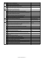
CONTENTS
NOTE FOR SERVICING
[1]
PRODUCT OUTLINE . . . . . . . . . . . . . . . . . . . . . . . . . . . . . . . . . . . . . . . . . . . . . . . 1-1
[2]
CONSUMABLE PARTS . . . . . . . . . . . . . . . . . . . . . . . . . . . . . . . . . . . . . . . . . . . . . 2-1
[3]
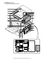
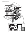
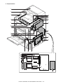
EXTERNAL VIEW AND INTERNAL STRUCTURE . . . . . . . . . . . . . . . . . . . . . . . . 3-1
[4]
ADJUSTMENTS AND SETTINGS . . . . . . . . . . . . . . . . . . . . . . . . . . . . . . . . . . . . . 4-1
[5]
SIMULATION . . . . . . . . . . . . . . . . . . . . . . . . . . . . . . . . . . . . . . . . . . . . . . . . . . . . . 5-1
[6]
TROUBLESHOOTING . . . . . . . . . . . . . . . . . . . . . . . . . . . . . . . . . . . . . . . . . . . . . . 6-1
[7]
FIRMWARE UPDATE . . . . . . . . . . . . . . . . . . . . . . . . . . . . . . . . . . . . . . . . . . . . . . . 7-1
[8]
MAINTENANCE . . . . . . . . . . . . . . . . . . . . . . . . . . . . . . . . . . . . . . . . . . . . . . . . . . . 8-1
[9]
DISASSEMBLY AND ASSEMBLY . . . . . . . . . . . . . . . . . . . . . . . . . . . . . . . . . . . . . 9-1
[10] VARIOUS STORAGE DATA HANDLING . . . . . . . . . . . . . . . . . . . . . . . . . . . . . . . 10-1
[11] SERVICE WEB PAGE . . . . . . . . . . . . . . . . . . . . . . . . . . . . . . . . . . . . . . . . . . . . . 11-1
[12] OPERATIONAL DESCRIPTIONS. . . . . . . . . . . . . . . . . . . . . . . . . . . . . . . . . . . . . 12-1
[13] ELECTRICAL SECTION. . . . . . . . . . . . . . . . . . . . . . . . . . . . . . . . . . . . . . . . . . . . 13-1
[14] SPECIFICATIONS . . . . . . . . . . . . . . . . . . . . . . . . . . . . . . . . . . . . . . . . . . . . . . . . 14-1
[15] TOOL LIST . . . . . . . . . . . . . . . . . . . . . . . . . . . . . . . . . . . . . . . . . . . . . . . . . . . . . . 15-1
Parts marked with " " are important for maintaining the safety of the set. Be sure to replace these parts with
specified ones for maintaining the safety and performance of the set.
SHARP CORPORATION
This document has been published to be used
for after sales service only.
The contents are subject to change without notice.
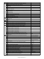
CONTENTS
NOTE FOR SERVICING
[7]
1. Outline . . . . . . . . . . . . . . . . . . . . . . . . . . . . . . . . . . . . . 7-1
2. Warning for servicing . . . . . . . . . . . . . . . . . . . . . . . . . . . . i
2. Update procedure . . . . . . . . . . . . . . . . . . . . . . . . . . . . 7-1
3. Note for installing site. . . . . . . . . . . . . . . . . . . . . . . . . . . . i
[8]
4. Note for handling PWB and electronic parts . . . . . . . . . .ii
6. Note for handling the drum unit, the transfer unit,
the developing unit. . . . . . . . . . . . . . . . . . . . . . . . . . . . . iii
7. Screw tightening torque . . . . . . . . . . . . . . . . . . . . . . . . . iii
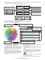
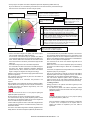
PRODUCT OUTLINE
1. System diagram . . . . . . . . . . . . . . . . . . . . . . . . . . . . . . 1-1
2. Option list . . . . . . . . . . . . . . . . . . . . . . . . . . . . . . . . . . . 1-5
[2]
[3]
[9]
DISASSEMBLY AND ASSEMBLY
1. Disassembly of Units . . . . . . . . . . . . . . . . . . . . . . . . . . 9-1
2. Disassembly and assembly of each unit . . . . . . . . . . 9-24
[10] VARIOUS STORAGE DATA HANDLING
1. HDD/SD card memory map . . . . . . . . . . . . . . . . . . . . 10-1
2. Maintenance parts list . . . . . . . . . . . . . . . . . . . . . . . . . 2-7
2. Necessary steps when replacing the PWB,
HDD and the SD Card . . . . . . . . . . . . . . . . . . . . . . . . 10-6
3. Definition of developer/drum life end . . . . . . . . . . . . . 2-19
3. HDD/SD card SIM format operation. . . . . . . . . . . . . 10-12
4. Production number identification . . . . . . . . . . . . . . . . 2-21
5. Environmental conditions . . . . . . . . . . . . . . . . . . . . . . 2-21
4. Necessary works and notes for replacement
of the mirroring kit HDD . . . . . . . . . . . . . . . . . . . . . . 10-14
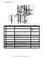
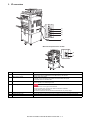
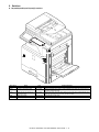
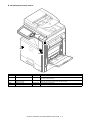
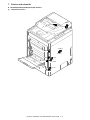
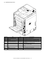
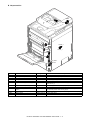
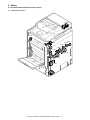
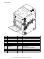
EXTERNAL VIEW AND INTERNAL STRUCTURE
5. Note for installing and repairing the mirroring kit . . . 10-17
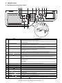
3. I/F connectors . . . . . . . . . . . . . . . . . . . . . . . . . . . . . . . 3-5
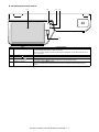
4. Operation panel . . . . . . . . . . . . . . . . . . . . . . . . . . . . . . 3-6
[11] SERVICE WEB PAGE
1. General . . . . . . . . . . . . . . . . . . . . . . . . . . . . . . . . . . . 11-1
2. Details and operation procedures . . . . . . . . . . . . . . . 11-1
[12] OPERATIONAL DESCRIPTIONS
5. Sensors and detectors . . . . . . . . . . . . . . . . . . . . . . . . . 3-8
1. Operation panel section . . . . . . . . . . . . . . . . . . . . . . . 12-1
6. Switches. . . . . . . . . . . . . . . . . . . . . . . . . . . . . . . . . . . 3-13
2. Scanner section . . . . . . . . . . . . . . . . . . . . . . . . . . . . . 12-6
7. Clutches and solenoids . . . . . . . . . . . . . . . . . . . . . . . 3-15
3. Manual paper feed section. . . . . . . . . . . . . . . . . . . . . 12-8
8. Motors . . . . . . . . . . . . . . . . . . . . . . . . . . . . . . . . . . . . 3-18
4. Tray paper feed section . . . . . . . . . . . . . . . . . . . . . . 12-13
9. Rollers . . . . . . . . . . . . . . . . . . . . . . . . . . . . . . . . . . . . 3-21
10. Lamps . . . . . . . . . . . . . . . . . . . . . . . . . . . . . . . . . . . . 3-26
5. Paper registration section
(Paper transport section) . . . . . . . . . . . . . . . . . . . . . 12-19
11. Fans and filter . . . . . . . . . . . . . . . . . . . . . . . . . . . . . . 3-29
6. Paper exit section. . . . . . . . . . . . . . . . . . . . . . . . . . . 12-23
12. Gates . . . . . . . . . . . . . . . . . . . . . . . . . . . . . . . . . . . . . 3-31
7. ADU section . . . . . . . . . . . . . . . . . . . . . . . . . . . . . . . 12-29
13. Heater . . . . . . . . . . . . . . . . . . . . . . . . . . . . . . . . . . . . 3-33
8. LSU section . . . . . . . . . . . . . . . . . . . . . . . . . . . . . . . 12-34
14. PWB/Memory device . . . . . . . . . . . . . . . . . . . . . . . . . 3-34
9. Process section . . . . . . . . . . . . . . . . . . . . . . . . . . . . 12-41
15. Fuses and Thermostats . . . . . . . . . . . . . . . . . . . . . . . 3-40
10. Fusing section . . . . . . . . . . . . . . . . . . . . . . . . . . . . . 12-79
16. Lock . . . . . . . . . . . . . . . . . . . . . . . . . . . . . . . . . . . . . . 3-43
11. RSPF section . . . . . . . . . . . . . . . . . . . . . . . . . . . . . . 12-90
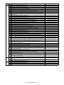
ADJUSTMENTS AND SETTINGS
12. Fan and filter . . . . . . . . . . . . . . . . . . . . . . . . . . . . . . 12-96
1. General . . . . . . . . . . . . . . . . . . . . . . . . . . . . . . . . . . . . 4-1
2. Adjustment item list . . . . . . . . . . . . . . . . . . . . . . . . . . . 4-1
13. Operations and specifications of counters . . . . . . . . 12-97
[13] ELECTRICAL SECTION
3. Details of adjustment . . . . . . . . . . . . . . . . . . . . . . . . . . 4-3
1. Block diagram . . . . . . . . . . . . . . . . . . . . . . . . . . . . . . 13-1
SIMULATION
2. Power line diagram . . . . . . . . . . . . . . . . . . . . . . . . . 13-26
1. General and purpose . . . . . . . . . . . . . . . . . . . . . . . . . . 5-1
2. Starting the simulation . . . . . . . . . . . . . . . . . . . . . . . . . 5-1
3. List of simulation codes . . . . . . . . . . . . . . . . . . . . . . . . 5-4
[6]
3. Maintenance list . . . . . . . . . . . . . . . . . . . . . . . . . . . . . . 8-4
CONSUMABLE PARTS
2. Internal structure . . . . . . . . . . . . . . . . . . . . . . . . . . . . . 3-4
[5]
2. Display of maintenance execution timing. . . . . . . . . . . 8-2
1. Supply system table. . . . . . . . . . . . . . . . . . . . . . . . . . . 2-1
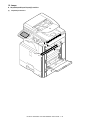
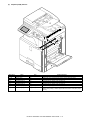
1. External view . . . . . . . . . . . . . . . . . . . . . . . . . . . . . . . . 3-1
[4]
MAINTENANCE
1. Works necessary when executing
the maintenance. . . . . . . . . . . . . . . . . . . . . . . . . . . . . . 8-1
5. Note for repairing/replacing the LSU . . . . . . . . . . . . . . . iii
[1]
FIRMWARE UPDATE
1. Precautions for servicing . . . . . . . . . . . . . . . . . . . . . . . . . i
3. Actual wiring chart . . . . . . . . . . . . . . . . . . . . . . . . . . 13-32
4. Signal list . . . . . . . . . . . . . . . . . . . . . . . . . . . . . . . . . 13-68
[14] SPECIFICATIONS
4. Details of simulation. . . . . . . . . . . . . . . . . . . . . . . . . . 5-10
1. 18cpm/20cpm machine . . . . . . . . . . . . . . . . . . . . . . . 14-1
TROUBLESHOOTING
2. 23cpm/31cpm(G) machine. . . . . . . . . . . . . . . . . . . . 14-10
1. Error code and troubleshooting . . . . . . . . . . . . . . . . . . 6-1
2. JAM and troubleshooting . . . . . . . . . . . . . . . . . . . . . . 6-38
3. Image send communication report code . . . . . . . . . . 6-49
4. Dial tone. . . . . . . . . . . . . . . . . . . . . . . . . . . . . . . . . . . 6-53
3. 26cpm/36cpm/31cpm(A) machine . . . . . . . . . . . . . . 14-19
4. List of parts included in the package
of developer . . . . . . . . . . . . . . . . . . . . . . . . . . . . . . . 14-30
[15] TOOL LIST. . . . . . . . . . . . . . . . . . . . . . . . . . . . . . . . . . . . 15-1
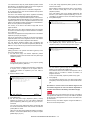
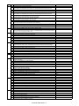
Symbols in this manual
The lists of symbols used in this manual are shown below.
The meaning of each symbol described in the table must be understood for proper servicing.
1. Symbols used for notes and
cautions
Symbol
Symbol
Meaning
CAUTION
Indicates a general
caution item.
HIGH TEMP
Be careful of a high
temperature in the
fusing section.
HIGH VOLTAGE
DANGER
HANDLE WITH
CARE
INHIBIT
Be careful of an electric
shock where a high
voltage is applied such
as the high voltage
PWB, the main charger,
and the process section.
Meaning
OK/GOOD
Indicates a correct
procedure or result in an
adjustment, etc.
NO GOOD
Indicates a wrong
procedure or result in an
adjustment, etc.
NOTE
Indicates a note.
IMPORTANT
Indicates an important
item.
REFER
Indicates a reference
page, etc.
NEW
Indicates a new
technology, a new
method, or a new item.
EXAMPLE
Indicates a description
using an example.
Indicates danger.
Indicates a part which
requires special care for
handling such as the
HDD, and the LSU.
2. Symbols used in the work
contents
Symbol
Meaning (Work content)
Adhesion
Indicates that a seal, etc.
is attached.
Adjustment
Indicates an adjustment.
Measure a
dimension or a
size.
Indicates that a
dimension or a length is
measured.
Apply grease
Indicates that grease is
to be applied.
Apply conductive
grease
Indicates conductive
grease is applied
Cleaning
(Dry)
Indicates clean with a
dry cloth.
Cleaning
(Wet)
Indicates clean with a
cloth dampened with
water.
Cleaning
(Alcohol)
Indicates clean with
alcohol.
Cleaning
(Blower)
Indicates cleaning is
done with a blower/
brush.
Indicates inhibit.
NO
ELECTROSTATIC
CHARGE
Be careful to keep away
from static electricity.
(PWB's and electric
parts)
NO DUST,
FINGER PRINT,
DIRT, SCRATCH
Be careful not to touch
directly, such as the
optical section, the
photoconductor, and the
DV roller.
Also be careful not to
scratch.
NO SCRATCH
NO LIGHT
NO SOLVENT
NO DISASSEMLE
Be careful not to expose
to light, such as the
photoconductor, and the
test chart.
Be careful not to use a
solvent in cleaning, etc.
Do not disassemble.
Not serviceable.
Example CCD unit.
Symbol
Meaning (Work content)
Symbol
Meaning (Work content)
Cleaning
(Vacuum)
Indicates that cleaning is
performed with a
vacuum cleaner.
Engage the pawl.
Cleaning
(Brush)
Indicates that cleaning is
performed with a brush.
Screw lock
Oil
Indicates that oil is
applied to lubricate.
Unlock
Apply powder.
Indicates that setting
power is applied to the
photoconductor drum,
the transfer belt, etc.
Turn OFF the
power.
Replace
Indicates that a part is
replaced.
Check
Indicates that a check
(replacement,
adjustment, cleaning) is
performed.
Cut
Indicates that cutting is
performed.
Loosen
Indicates that a screw is
loosened.
Connect
Disconnect the
power plug.
3. Symbols used for kinds of parts
Symbol
Meaning (Kinds of parts)
Maintenance
part
Indicates a part which is
replaced in a maintenance
procedure.
Consumable
part
Indicates a consumable
part such as a
photoconductor,
developer, a transfer belt,
etc.
Waste part
Indicates a waste part
which is consumed but
excluded from the above
consumable parts. (A
roller, a seal, etc.)
Unit part
Indicates a part which is
designated as a unit.
Included part
Indicates a part which is
included in the package
Indicates that a
connector is connected.
Disconnect
Indicates that a
connector is
disconnected.
Remove a
harness.
Indicates that a harness
is unsecured.
Attach a harness.
Indicates that a screw is
secured with adhesive.
Indicates that a harness
is secured.
4. Symbols used for additional
descriptions
Remove a clamp.
Attach a clamp.
Symbol
Meaning
View from the
top
Release a hook.
Fix a hook.
Disengage the
pawl.
Indicates that a hook is
released.
Indicates that a hook is
fixed.
View from the
bottom
View from the
front
View from the
back
Indicates from which
angle the drawing is
viewed.
MX-3610N
NOTE
FOR SERVICING
• Do not damage,
break, or stress the power cord.
Service
Manual
Do not put heavy objects on the power cable. Do not stress, forcibly bend, or pull the power cord.
1. Precautions for servicing
It may cause a fire or an electric shock.
• When servicing, disconnect the power plug, the printer cable, the
network cable, and the telephone line from the machine, except
when performing the communication test, etc.
It may cause an injury or an electric shock.
• There is a high temperature area inside the machine. Use
extreme care when servicing.
It may cause a burn.
• There is a high voltage section inside the machine which may
cause an electric shock. Be careful when servicing.
• Do not disassemble the laser unit. Do not insert a reflective
material such as a screwdriver in the laser beam path.
It may damage eyes by reflection of laser beams.
• When servicing with the machine operating, be careful not to
squeeze you hands by the chain, the belt, the gear, and other
driving sections.
• Do not leave the machine with the cabinet disassembled.
Do not allow any person other than a serviceman to touch inside
the machine. It may cause an electric shock, a burn, or an injury.
• When servicing, do not breathe toner, developer, and ink excessively. Do not get them in the eyes.
If toner, developer, or ink enters your eyes, wash it away with
water immediately, and consult a doctor if necessary.
• Keep the power cable away from a heat source.
Do not insert the power plug with dust on it into a power outlet.
It may cause a fire or an electric shock.
• Do not place liquids or foreign metallic objects inside the
machine.
It may cause a fire or an electric shock.
• Do not touch the power cord, insert the phone jack, operate the
machine, or perform service on the machine with wet or oily
hands.
It may cause an electric shock.
3. Note for installing site
Do not install the machine at the following sites.
• Place of high temperature, high humidity, low temperature,
low humidity, place under an extreme change in temperature
and humidity.
Paper may get damp and form condensation inside the machine,
causing paper jam or copy dirt.
For operating and storing conditions, refer to the specifications
described later.
• The machine has got sharp edges inside. Be careful not to damage fingers when servicing.
• Do not throw toner or a toner cartridge in a fire. Otherwise, toner
may ignite and burn you.
• When replacing a lithium battery on a PWB, only use the specified replacement battery.
If a battery of different specification is used, it may cause a
machine malfunction or breakdown.
• When carrying a unit with PWB or electronic parts installed to it,
be sure to put it in an anti-static-electricity bag.
• Place of extreme vibrations
It may cause a breakdown.
It may otherwise cause a machine breakdown or malfunction.
CAUTION
DOUBLE POLE/NEUTRAL FUSING
(200V series only)
2. Warning for servicing
• Be sure to connect the power cord only to a power outlet that
meets the specified voltage and current requirements.
Avoid complex wiring, which may lead to a fire or an electric
shock.
It may cause a fire or an electric shock.
• If there is any abnormality such as a smoke or an abnormal
smell, interrupt the job and disconnect the power plug.
• Poorly ventilated place
An electrostatic type copier will produce ozone.
The quantity of ozone produced is designed to a low level so as
not to affect human bodies. However, continuous use of such a
machine may produce an ozone smell. Install the machine in a
well ventilated place.
It may cause a fire or an electric shock.
• Be sure to connect the grounding wire. If an electric leakage
occurs without grounding, a fire or an electric shock may result.
To protect the machine and the power unit from lightening,
grounding must be made.
• When connecting the grounding wire, never connect it to the following points.
Gas tube
Lightning conductor
A water pipe or a water faucet, which is not recognized as a
grounding object by the authorities.
Grounding wire for telephone line
It may cause an explosion, a fire or an electric shock.
MX-3610N NOTE FOR SERVICING - i
• Place of direct sunlight.
Plastic parts and ink may be deformed, discolored, or may
undergo qualitative change.
It may cause a breakdown or output quality problems.
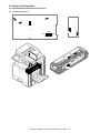
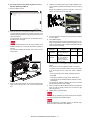
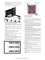
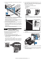
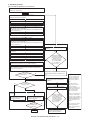
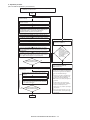
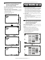
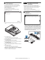
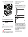
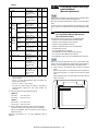
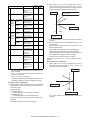
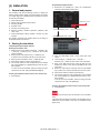
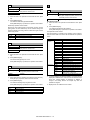
4. Note for handling PWB and electronic
parts
When handling the PWB and the electronic parts, be sure to
observe the following precautions in order to prevent against damage by static electricity.
• When in transit or storing, put the parts in an anti-static bag or an
anti-static case and do not touch them with bare hands.
• Place which is full of organic gases such as ammonium
The organic photo-conductor (OPC) drum used in the machine
may undergo qualitative change due to organic gases such as
ammonium.
Installation of this machine near a diazo-type copier and blue
print machine may result in poor quality output.
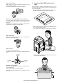
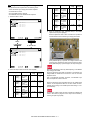
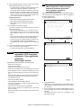
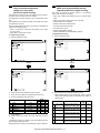
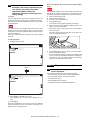
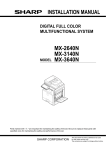
• When and after removing the parts from an anti-static bag (case),
use an earth band as shown below:
• Put an earth band to your arm, and connect it to the machine.
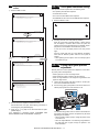
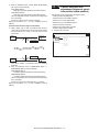
• Place of much dust
When dust or contaminants enters the machine, it may cause a
breakdown or poor quality output.
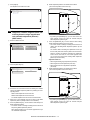
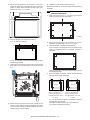
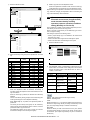
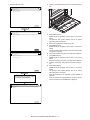
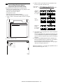
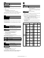
• Place near a wall
The machine will require ventilation.
If ventilation is not proper, poor output or machine failure may
result.
11-13/16"
(30cm)
11-13/16"
(30cm)
• When repairing or replacing an electronic part, perform the
procedure on an anti-static mat.
17-23/32"
(45cm)
• Unstable or irregular surface
If the machine is dropped or tips over, it may cause injury or
machine malfunction.
Use an optional desk or an exclusive-use desk.
When using the optional desk, be sure to fix the adjuster and lock
the casters.
MX-3610N NOTE FOR SERVICING - ii
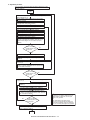
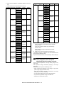
5. Note for repairing/replacing the LSU
When repairing or replacing, be sure to observe the following
items.
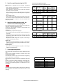
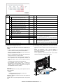
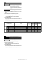
Screw kinds and tightening torques
Normal screws, set screws (including step screws)
• When repairing or replacing the LSU, be sure to disconnect the
power plug from the power outlet.
Screw
diameter
Material to be
fixed
• When repairing or replacing the LSU, follow the procedures
described in this Service Manual.
M2.6
M3
M4
Steel plate
Steel plate
Steel plate
• When checking the operations after repairing the LSU, keep all
the parts including the cover installed and perform the operation
check.
• Do not modify the LSU.
• When visually checking the inside of the machine for the operation check, be careful not to allow laser beams to enter the eyes.
If the above precaution is neglected or the LSU is modified, ones
safety may be at risk.
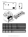
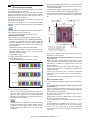
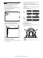
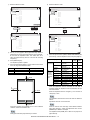
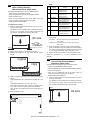
6. Note for handling the drum unit, the
transfer unit, the developing unit
When handling the OPC drum unit, the transfer unit, and the developing unit, strictly observe the following items.
If these items are neglected, a trouble may be generated in the
copy and print image quality.
Drum unit
Tightening
torque
(Nm)
0.8 - 1.0
1.0 - 1.2
1.6 - 1.8
Tightening
torque
(kgfcm)
8 - 10
10 - 12
16 - 18
Tightening
torque
(lbft)
0.6 - 0.7
0.7 - 0.9
1.2 - 1.3
Tightening
torque
(Nm)
1.0 - 1.2
Tightening
torque
(kgfcm)
10 - 12
Tightening
torque
(lbft)
0.7 - 0.9
1.6 - 1.8
16 - 18
1.2 - 1.3
0.6 - 0.8
6-8
0.4 - 0.6
1.2 - 1.4
12 - 14
0.9 - 1.0
Tightening
torque
(Nm)
0.6 - 0.8
1.0 - 1.2
Tightening
torque
(kgfcm)
6-8
10 - 12
Tightening
torque
(lbft)
0.4 - 0.6
0.7 - 0.9
Tapping screws (for iron)
Screw
diameter
Material to be
fixed
M3
Steel plate
(Plate thickness
0.8mm or above)
Steel plate
(Plate thickness
0.8mm or above)
Steel plate
(Plate thickness
less than 0.8mm)
Steel plate
(Plate thickness
less than 0.8mm)
M4
M3
M4
Tapping screw (for plastic)
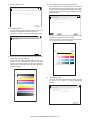
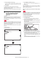
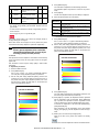
• Avoid working at a place with strong lights.
• Do not expose the OPC drum to lights including interior lights for
a long time.
• When the OPC drum is removed from the machine, cover it with
light blocking material. (When using paper, use about 10 sheets
of paper to cover it.)
Screw
diameter
Material to be
fixed
M3
M4
Plastic resin
Plastic resin
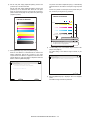
• Be careful not to attach fingerprints, oil, grease, or other foreign
material on the OPC drum surface.
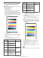
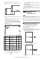
Transfer unit
• Be careful not to leave fingerprints, oil, grease, or other foreign
material on the transfer roller, primary transfer belt, and the secondary transfer belt.
Developing unit
• Be careful not to leave fingerprints, oil, grease, or other foreign
material on the developing unit.
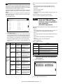
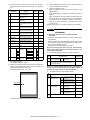
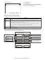
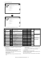
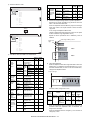
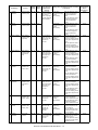
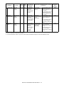
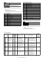
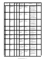
7. Screw tightening torque
The screws used in this machine are largely classified into three
types.
These types are classified according to the shape of the screw
grooves and use positions.
The table below shows the types of the screws and the tightening
torques depending on the use position.
When tightening the screws for repair or maintenance, refer to the
table.
However, for the other conditions of tightening screws than specified on this table, or under special circumstances, the details are
described on the separate page. Refer to the descriptions on such
an exception.
Name in the manual
18cpm machine
20cpm machine
23cpm machine
26cpm machine
31cpm(G) machine
31cpm(A) machine
31cpm machine
36cpm machine
Especially for the screw fixing positions where there is an electrode
or a current flows, use enough care to tighten securely to avoid
loosening.
MX-3610N NOTE FOR SERVICING - iii
Model name
MX-1810U
MX-2010U
MX-2310U
MX-2610N
MX-3111U
MX-3110N
MX-3111U/MX-3110N
MX-3610N
MX-3610N
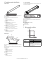
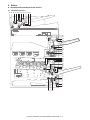
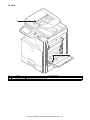
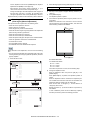
[1]
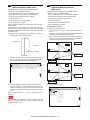
PRODUCT OUTLINE
Service Manual
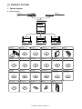
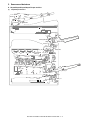
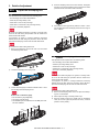
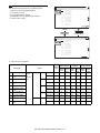
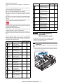
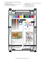
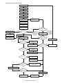
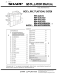
1. System diagram
A. 18cpm machine
MX-RP12
MX-VR11
REVERSING SINGLE PASS
FEEDER
DOCUMENT COVER
MX-1810U
DIGITAL FULL COLOR
MULTIFUNCTIONAL SYSTEM
MX-DE12
MX-DE13
MX-DE14
STAND/1x500 SHEET
PAPER DRAWER
STAND/2x500 SHEET
PAPER DRAWER
STAND/3x500 SHEET
PAPER DRAWER
MX-PB14
MX-PK11
MX-PUX1
MX-PF10
MX-FX11
AR-SU1
PRINTER EXPANSION KIT
PS3 EXPANSION KIT
XPS EXPANSION KIT
BARCODE FONT KIT
FACSIMILE EXPANSION
KIT
STAMP UNIT
MX-FWX1
MX-USX1
MX-USX5
MX-US10
MX-US50
MX-USA0
INTERNET FAX
EXPANSION KIT
SHARPDESK 1 LICENSE
KIT
SHARPDESK 5 LICENSE
KIT
SHARPDESK 10 LICENSE
KIT
SHARPDESK 50 LICENSE
KIT
SHARPDESK 100 LICENSE
KIT
MX-AMX1
MX-AMX2
MX-AMX3
MX-UN01A
MX-UN05A
MX-UN10A
APPLICATION
INTEGRATION MODULE
APPLICATION
COMMUNICATION MODULE
EXTERNAL ACCOUNT
MODULE
Sharp OSA Network Scanner
Tool 1 License Kit
Sharp OSA Network Scanner
Tool 5 License Kit
Sharp OSA Network Scanner
Tool 10 License Kit
MX-UN50A
MX-UN1HA
MX-SM10
AR-SV1
MX-HD11
Sharp OSA Network Scanner
Tool 50 License Kit
Sharp OSA Network Scanner
Tool 100 License Kit
EXPANSION MEMORY
BOARD
STAMP CARTRIDGE
HARD DISK EXPANSION
KIT
MX-3610N PRODUCT OUTLINE 1 – 1
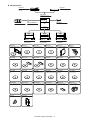
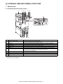
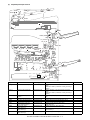
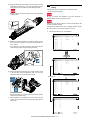
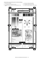
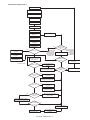
B. 20cpm machine
MX-RP12
MX-VR11
REVERSING SINGLE PASS
FEEDER
DOCUMENT COVER
MX-2010U
DIGITAL FULL COLOR
MULTIFUNCTIONAL SYSTEM
MX-FN17
MX-PN11A/B/C/D
FINISHER
PUNCH MODULE
MX-TR12
EXIT TRAY UNIT
MX-DE12
MX-DE13
MX-DE14
STAND/1x500 SHEET
PAPER DRAWER
STAND/2x500 SHEET
PAPER DRAWER
STAND/3x500 SHEET
PAPER DRAWER
MX-PB14
MX-PK11
MX-PUX1
MX-PF10
MX-FX11
AR-SU1
PRINTER EXPANSION KIT
PS3 EXPANSION KIT
XPS EXPANSION KIT
BARCODE FONT KIT
FACSIMILE EXPANSION
KIT
STAMP UNIT
MX-FWX1
MX-FR25U
MX-FR34U
MX-USX1
MX-USX5
MX-US10
INTERNET FAX
EXPANSION KIT
DATA SECURITY KIT
DATA SECURITY KIT
SHARPDESK 1 LICENSE
KIT
SHARPDESK 5 LICENSE
KIT
SHARPDESK 10 LICENSE
KIT
MX-US50
MX-USA0
MX-AMX1
MX-AMX2
MX-AMX3
MX-UN01A
SHARPDESK 50 LICENSE
KIT
SHARPDESK 100 LICENSE
KIT
APPLICATION
INTEGRATION MODULE
APPLICATION
COMMUNICATION MODULE
EXTERNAL ACCOUNT
MODULE
Sharp OSA Network Scanner
Tool 1 License Kit
MX-UN05A
MX-UN10A
MX-UN50A
MX-UN1HA
MX-SM10
MX-SCX1
Sharp OSA Network Scanner
Tool 5 License Kit
Sharp OSA Network Scanner
Tool 10 License Kit
Sharp OSA Network Scanner
Tool 50 License Kit
Sharp OSA Network Scanner
Tool 100 License Kit
EXPANSION MEMORY
BOARD
STAPLE CARTRIDGE
AR-SV1
MX-HD10
STAMP CARTRIDGE
HARD DISK EXPANSION
KIT
MX-3610N PRODUCT OUTLINE 1 – 2
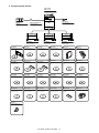
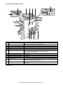
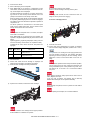
C. 23cpm/31cpm(G) machine
MX-2310U
MX-3111U
DIGITAL FULL COLOR
MULTIFUNCTIONAL SYSTEM
MX-FN17
MX-PN11A/B/C/D
FINISHER
PUNCH MODULE
MX-TR12
EXIT TRAY UNIT
MX-DE12
MX-DE13
MX-DE14
STAND/1x500 SHEET
PAPER DRAWER
STAND/2x500 SHEET
PAPER DRAWER
STAND/3x500 SHEET
PAPER DRAWER
MX-PB14
MX-PK11
MX-PUX1
MX-PF10
MX-FX11
AR-SU1
PRINTER EXPANSION KIT
PS3 EXPANSION KIT
XPS EXPANSION KIT
BARCODE FONT KIT
FACSIMILE EXPANSION
KIT
STAMP UNIT
MX-FWX1
MX-FR25U
MX-FR34U
MX-USX1
MX-USX5
MX-US10
INTERNET FAX
EXPANSION KIT
DATA SECURITY KIT
DATA SECURITY KIT
SHARPDESK 1 LICENSE
KIT
SHARPDESK 5 LICENSE
KIT
SHARPDESK 10 LICENSE
KIT
MX-US50
MX-USA0
MX-AMX1
MX-AMX2
MX-AMX3
MX-UN01A
SHARPDESK 50 LICENSE
KIT
SHARPDESK 100 LICENSE
KIT
APPLICATION
INTEGRATION MODULE
APPLICATION
COMMUNICATION MODULE
EXTERNAL ACCOUNT
MODULE
Sharp OSA Network Scanner
Tool 1 License Kit
MX-UN05A
MX-UN10A
MX-UN50A
MX-UN1HA
MX-SM10
MX-SCX1
Sharp OSA Network Scanner
Tool 5 License Kit
Sharp OSA Network Scanner
Tool 10 License Kit
Sharp OSA Network Scanner
Tool 50 License Kit
Sharp OSA Network Scanner
Tool 100 License Kit
EXPANSION MEMORY
BOARD
STAPLE CARTRIDGE
AR-SV1
STAMP CARTRIDGE
MX-3610N PRODUCT OUTLINE 1 – 3
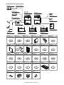
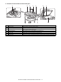
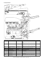
D. 26cpm/36cpm/31cpm(A) machine
MX-FN17
MX-PN11A/B/C/D
FINISHER
PUNCH MODULE
MX-TU12
EXIT TRAY CABINET
MX-2610N
MX-3110N
MX-3610N
DIGITAL FULL COLOR
MULTIFUNCTIONAL SYSTEM
DIGITAL FULL COLOR
MULTIFUNCTIONAL SYSTEM
MX-TR12
EXIT TRAY UNIT
MX-PNX5A/B/C/D
PUNCH MODULE
MX-TR13
EXIT TRAY UNIT
MX-RB10
PAPER PASS UNIT
MX-LC11
LARGE CAPACITY TRAY
MX-FN10
MX-DE12
MX-DE13
MX-DE14
FINISHER
STAND/1x500 SHEET
PAPER DRAWER
STAND/2x500 SHEET
PAPER DRAWER
STAND/3x500 SHEET
PAPER DRAWER
MX-PK11
MX-PUX1
MX-PF10
MX-FX11
AR-SU1
MX-FWX1
PS3 EXPANSION KIT
XPS EXPANSION KIT
BARCODE FONT KIT
FACSIMILE EXPANSION
KIT
STAMP UNIT
INTERNET FAX
EXPANSION KIT
MX-EB11
MX-FR30U
MX-EB12
MX-USX1
MX-USX5
MX-US10
ENHANCED COMPRESSION
KIT
DATA SECURITY KIT
MIRRORING KIT
SHARPDESK 1 LICENSE
KIT
SHARPDESK 5 LICENSE
KIT
SHARPDESK 10 LICENSE
KIT
MX-US50
MX-USA0
MX-AMX1
MX-AMX2
MX-AMX3
MX-UN01A
SHARPDESK 50 LICENSE
KIT
SHARPDESK 100 LICENSE
KIT
APPLICATION
INTEGRATION MODULE
APPLICATION
COMMUNICATION MODULE
EXTERNAL ACCOUNT
MODULE
Sharp OSA Network Scanner
Tool 1 License Kit
MX-UN05A
MX-UN10A
MX-UN50A
MX-UN1HA
MX-KB11
MX-AM10
Sharp OSA Network Scanner
Tool 5 License Kit
Sharp OSA Network Scanner
Tool 10 License Kit
Sharp OSA Network Scanner
Tool 50 License Kit
Sharp OSA Network Scanner
Tool 100 License Kit
KEYBOARD
WEB BROWSING EXPANSION
KIT
MX-SM10
MX-SCX1
AR-SC3
AR-SV1
EXPANSION MEMORY
BOARD
STAPLE CARTRIDGE
STAPLE CARTRIDGE
STAMP CARTRIDGE
MX-3610N PRODUCT OUTLINE 1 – 4
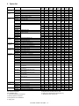
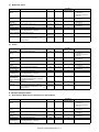
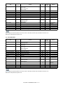
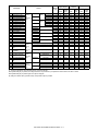
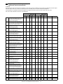
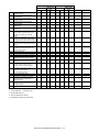
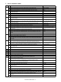
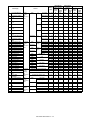
2. Option list
Model name
Document
feed system
Paper feed
system
Paper exit
system
Printer
expansion
Image send
expansion
Authentication/
Security
Application/
Solution
MX-RP12
MX-VR11
MX-DE12
MX-DE13
MX-DE14
MX-LC11
MX-TR12
MX-TR13
MX-TU12
REVERSING SINGLE PASS FEEDER
DOCUMENT COVER
STAND/1x500 SHEET PAPER DRAWER
STAND/2x500 SHEET PAPER DRAWER
STAND/3x500 SHEET PAPER DRAWER
LARGE CAPACITY TRAY
EXIT TRAY UNIT
EXIT TRAY UNIT
EXIT TRAY CABINET
MX-FN17
MX-PN11A
MX-PN11B
MX-PN11C
MX-PN11D
MX-RB10
MX-FN10
MX-PNX5A
MX-PNX5B
MX-PNX5C
MX-PNX5D
MX-PB14
MX-PK11
MX-PUX1
MX-PF10
MX-FX11
AR-SU1
MX-FWX1
MX-EB11
MX-FR25U
MX-FR34U
MX-FR30U
MX-EB12
MX-USX1
MX-USX5
MX-US10
MX-US50
MX-USA0
MX-AMX1
MX-AMX2
MX-AMX3
MX-UN01A
FINISHER
PUNCH MODULE
MX-KB11
MX-AM10
WEB BROWSING EXPANSION KIT
MX-SM10
MX-SCX1
AR-SC3
AR-SV1
MX-HD10
MX-HD11
EXPANSION MEMORY BOARD
STAPLE CARTRIDGE
STAPLE CARTRIDGE
STAMP CARTRIDGE
HARD DISK EXPANSION KIT
HARD DISK EXPANSION KIT
MX-UN10A
MX-UN50A
MX-UN1HA
Other
PAPER PASS UNIT
FINISHER
PUNCH MODULE
PRINTER EXPANSION KIT
PS3 EXPANSION KIT
XPS EXPANSION KIT
BARCODE FONT KIT
FACSIMILE EXPANSION KIT
STAMP UNIT
INTERNET FAX EXPANSION KIT
ENHANCED COMPRESSION KIT
DATA SECURITY KIT
DATA SECURITY KIT
DATA SECURITY KIT
MIRRORING KIT
SHARPDESK 1 LICENSE KIT
Sharpdesk 5 license kit
SHARPDESK 10 LICENSE KIT
SHARPDESK 50 LICENSE KIT
SHARPDESK 100 LICENSE KIT
APPLICATION INTEGRATION MODULE
APPLICATION COMMUNICATION MODULE
EXTERNAL ACCOUNT MODULE
Sharp OSA Network Scanner Tool
1 License Kit
Sharp OSA Network Scanner Tool
5 License Kit
Sharp OSA Network Scanner Tool
10 License Kit
Sharp OSA Network Scanner Tool
50 License Kit
Sharp OSA Network Scanner Tool
100 License Kit
KEYBOARD
MX-UN05A
Memory
Service
Name
MX1810U
OPT
OPT
OPT
OPT
OPT
---------
MX2010U
OPT
OPT
OPT
OPT
OPT
--OPT
--STD
MX2310U
STD
--OPT
OPT
OPT
--OPT
--STD
MX3111U
STD
--OPT
OPT
OPT
--OPT
--STD
OPT
OPT
OPT
OPT
OPT
------------OPT
OPT
OPT
OPT
OPT
OPT
OPT
----OPT
----OPT
OPT
OPT
OPT
OPT
OPT
OPT
OPT
OPT
MX2610N
STD
--OPT
OPT
OPT
OPT
OPT
--STD/
OPT
OPT
OPT
OPT
OPT
OPT
OPT
OPT
OPT
OPT
OPT
OPT
STD
OPT
OPT
OPT
OPT
OPT
OPT
OPT
----OPT
OPT
OPT
OPT
OPT
OPT
OPT
OPT
OPT
OPT
OPT
MX3110N
STD
--OPT
OPT
OPT
OPT
OPT
--STD/
OPT
OPT
OPT
OPT
OPT
OPT
OPT
OPT
OPT
OPT
OPT
OPT
STD
OPT
OPT
OPT
OPT
OPT
OPT
OPT
----OPT
OPT
OPT
OPT
OPT
OPT
OPT
OPT
OPT
OPT
OPT
MX3610N
STD
--OPT
OPT
OPT
OPT
--OPT
STD/
OPT
OPT
OPT
OPT
OPT
OPT
OPT
OPT
OPT
OPT
OPT
OPT
STD
OPT
OPT
OPT
OPT
OPT
OPT
OPT
----OPT
OPT
OPT
OPT
OPT
OPT
OPT
OPT
OPT
OPT
OPT
----------------------OPT
OPT
OPT
OPT
OPT
OPT
OPT
----------OPT
OPT
OPT
OPT
OPT
OPT
OPT
OPT
OPT
OPT
OPT
OPT
OPT
OPT
------------OPT
OPT
OPT
OPT
OPT
OPT
OPT
--OPT
OPT
----OPT
OPT
OPT
OPT
OPT
OPT
OPT
OPT
OPT
OPT
OPT
OPT
OPT
OPT
------------OPT
OPT
OPT
OPT
OPT
OPT
OPT
--OPT
OPT
----OPT
OPT
OPT
OPT
OPT
OPT
OPT
OPT
OPT
OPT
OPT
OPT
OPT
OPT
OPT
OPT
OPT
OPT
OPT
OPT
OPT
OPT
OPT
OPT
OPT
OPT
OPT
OPT
OPT
OPT
OPT
OPT
OPT
OPT
OPT
OPT
OPT
---
---
---
---
OPT
---
---
---
---
OPT
STD/
OPT
OPT
OPT
----OPT
--OPT
OPT
OPT
--OPT
OPT
---
OPT
OPT
--OPT
STD
---
OPT
OPT
--OPT
STD
---
OPT
OPT
OPT
OPT
STD
---
OPT
OPT
OPT
OPT
STD
---
STD/
OPT
STD/
OPT
OPT
OPT
OPT
OPT
STD
---
STD: Standard equipment
*5: Required when the XPS printer is used.
OPT: Installable option
*6: Option set for North America and Europe only.
*1: The printer expansion kit is required.
*7: Standard for North America only.
*2: Memory expansion is required.
*3: No support for some destinations.
*4: Supply parts
MX-3610N PRODUCT OUTLINE 1 – 5
Remarks
*6
*1
*1 *2
*1
*3
*7
*7
*5
*4
*4
[2] CONSUMABLE PARTS
MX-3610N
Service Manual
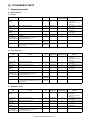
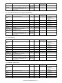
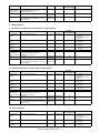
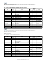
1. Supply system table
A. 18cpm machine
(1) Europe
Toner cartridge
(Black)
Toner cartridge (Black toner)
x1
18K
MX-23GT-BA
Quantity in
collective package
10
Toner cartridge
(Cyan)
Toner cartridge
(Magenta)
Toner cartridge
(Yellow)
Developer (Black)
Developer
(Cyan/Magenta/
Yellow: 3 colors/set)
Drum
Toner cartridge (Cyan toner)
x1
10K
MX-23GT-CA
10
Toner cartridge (Magenta toner)
x1
10K
MX-23GT-MA
10
Toner cartridge (Yellow toner)
x1
10K
MX-23GT-YA
10
Developer (Black developer)
Developer
(Cyan/Magenta/Yellow: 3 colors/set)
(Developer (each colors))
OPC drum
x1
x1
80K
50K
MX-36GV-BA
MX-36GV-SA
10
10
x1
MX-36GR-SA
10
OPC drum unit (Process unit + OPC drum)
Color identification seal (B/C/M/Y) x 1 each
Charger cleaner
x1
x1
x1
80K (Black)
50K (Color)
80K (Black)
50K (Color)
MX-36GU-SA
10
Life
Model name
Item
Drum unit
Content
Life
Model name
Remarks
* Life: A4/Letter size at area
coverage 5%
(Reference: 15K for A4/
Letter 6%)
* Life: A4/Letter size at area
coverage 5%
* Life: A4/Letter size at area
coverage 5%
* Life: A4/Letter size at area
coverage 5%
(2) Asia, Hong Kong
Toner cartridge
(Black)
Toner cartridge (Black toner)
x1
18K
MX-23AT-BA
Quantity in
collective package
10
Toner cartridge
(Cyan)
Toner cartridge
(Magenta)
Toner cartridge
(Yellow)
Developer (Black)
Developer
(Cyan/Magenta/
Yellow: 3 colors/set)
Drum
Toner cartridge (Cyan toner)
x1
10K
MX-23AT-CA
10
Toner cartridge (Magenta toner)
x1
10K
MX-23AT-MA
10
Toner cartridge (Yellow toner)
x1
10K
MX-23AT-YA
10
Developer (Black developer)
Developer
(Cyan/Magenta/Yellow: 3 colors/set)
(Developer (each colors))
OPC drum
x1
x1
80K
50K
MX-36AV-BA
MX-36AV-SA
10
10
x1
MX-36AR-SA
10
OPC drum unit (Process unit + OPC drum)
Color identification seal (B/C/M/Y) x 1 each
Charger cleaner
x1
x1
x1
80K (Black)
50K (Color)
80K (Black)
50K (Color)
MX-36AU-SA
10
Life
Model name
Item
Drum unit
Content
Remarks
* Life: A4/Letter size at area
coverage 5%
(Reference: 15K for A4/
Letter 6%)
* Life: A4/Letter size at area
coverage 5%
* Life: A4/Letter size at area
coverage 5%
* Life: A4/Letter size at area
coverage 5%
(3) Middle East, Africa
Toner cartridge
(Black)
Toner cartridge (Black toner)
x1
18K
MX-23FT-BA
Quantity in
collective package
10
Toner cartridge
(Cyan)
Toner cartridge
(Magenta)
Toner cartridge
(Yellow)
Developer (Black)
Developer
(Cyan/Magenta/
Yellow: 3 colors/set)
Toner cartridge (Cyan toner)
x1
10K
MX-23FT-CA
10
Toner cartridge (Magenta toner)
x1
10K
MX-23FT-MA
10
Toner cartridge (Yellow toner)
x1
10K
MX-23FT-YA
10
Developer (Black developer)
Developer
(Cyan/Magenta/Yellow: 3 colors/set)
(Developer (each colors))
x1
x1
80K
50K
MX-36FV-BA
MX-36FV-SA
10
10
Item
Content
MX-3610N CONSUMABLE PARTS 2 – 1
Remarks
* Life: A4/Letter size at area
coverage 5%
(Reference: 15K for A4/
Letter 6%)
* Life: A4/Letter size at area
coverage 5%
* Life: A4/Letter size at area
coverage 5%
* Life: A4/Letter size at area
coverage 5%
Item
Content
Drum
OPC drum
x1
Drum unit
OPC drum unit (Process unit + OPC drum)
Color identification seal (B/C/M/Y) x 1 each
Charger cleaner
x1
x1
x1
Life
Model name
80K (Black)
50K (Color)
80K (Black)
50K (Color)
MX-36FR-SA
Quantity in
collective package
10
MX-36FU-SA
10
Life
Model name
Remarks
(4) Taiwan
Toner cartridge
(Black)
Toner cartridge (Black toner)
x1
18K
MX-23FT-BA
Quantity in
collective package
10
Toner cartridge
(Cyan)
Toner cartridge
(Magenta)
Toner cartridge
(Yellow)
Toner Cartridge
(Special Magenta)
Developer (Black)
Developer
(Cyan/Magenta/
Yellow: 3 colors/set)
Developer (Cyan/
Special Magenta/
Yellow: 3 colors/set)
Toner cartridge (Cyan toner)
x1
10K
MX-23FT-CA
10
Toner cartridge (Magenta toner)
x1
10K
MX-23FT-MA
10
Toner cartridge (Yellow toner)
x1
10K
MX-23FT-YA
10
Toner Cartridge (Special Magenta)
x1
10K
MX-23FT-MP
10
Developer (Black developer)
Developer
(Cyan/Magenta/Yellow: 3 colors/set)
(Developer (each colors))
Developer
(Cyan/Special Magenta/Yellow: 3 colors/set)
(Developer (each colors))
OPC drum
x1
x1
80K
50K
MX-36FV-BA
MX-36FV-SA
10
10
x1
80K (Black)
50K (Color)
MX-23FV-SP
10
x1
80K (Black)
50K (Color)
100K (Black)
60K (Color)
MX-36FR-SA
10
MX-36FU-SA
10
Item
Drum
Drum unit
Content
OPC drum unit (Process unit + OPC drum)
Color identification seal (B/C/M/Y) x 1 each
Charger cleaner
x1
x1
x1
Remarks
* Life: A4/Letter size at area
coverage 5%
(Reference: 15K for A4/
Letter 6%)
* Life: A4/Letter size at area
coverage 5%
* Life: A4/Letter size at area
coverage 5%
* Life: A4/Letter size at area
coverage 5%
* Life: A4/Letter size at area
coverage 5%
B. 23cpm machine
(1) North America, Middle America, South America (Except Brazil)
Toner cartridge
(Black)
Toner cartridge (Black toner)
x1
18K
MX-23NT-BA
Quantity in
collective package
10
Toner cartridge
(Cyan)
Toner cartridge
(Magenta)
Toner cartridge
(Yellow)
Developer (Black)
Developer
(Cyan/Magenta/
Yellow: 3 colors/set)
Drum
Toner cartridge (Cyan toner)
x1
10K
MX-23NT-CA
10
Toner cartridge (Magenta toner)
x1
10K
MX-23NT-MA
10
Toner cartridge (Yellow toner)
x1
10K
MX-23NT-YA
10
Developer (Black developer)
Developer
(Cyan/Magenta/Yellow: 3 colors/set)
(Developer (each colors))
OPC drum
x1
x1
100K
60K
MX-36NV-BA
MX-36NV-SA
10
10
x1
MX-36NR-SA
10
OPC drum unit (Process unit + OPC drum)
Color identification seal (B/C/M/Y) x 1 each
Charger cleaner
x1
x1
x1
100K (Black)
60K (Color)
100K (Black)
60K (Color)
MX-36NU-SA
10
Item
Drum unit
Content
Life
Model name
Remarks
* Life: A4/Letter size at area
coverage 5%
(Reference: 15K for A4/
Letter 6%)
* Life: A4/Letter size at area
coverage 5%
* Life: A4/Letter size at area
coverage 5%
* Life: A4/Letter size at area
coverage 5%
C. 31cpm(G) machine
(1) North America, Middle America, South America (Except Brazil)
Item
Toner cartridge
(Black)
Content
Toner cartridge (Black toner)
x1
Life
Model name
18K
MX-23NT-BA
MX-3610N CONSUMABLE PARTS 2 – 2
Quantity in
collective package
10
Remarks
* Life: A4/Letter size at area
coverage 5%
(Reference: 15K for A4/
Letter 6%)
Toner cartridge (Cyan toner)
x1
10K
MX-23NT-CA
Quantity in
collective package
10
Toner cartridge (Magenta toner)
x1
10K
MX-23NT-MA
10
Toner cartridge (Yellow toner)
x1
10K
MX-23NT-YA
10
Developer (Black developer)
Developer
(Cyan/Magenta/Yellow: 3 colors/set)
(Developer (each colors))
OPC drum
x1
x1
100K
60K
MX-36NV-BA
MX-36NV-SA
10
10
x1
MX-36NR-SA
10
OPC drum unit (Process unit + OPC drum)
Color identification seal (B/C/M/Y) x 1 each
Charger cleaner
x1
x1
x1
100K (Black)
60K (Color)
100K (Black)
60K (Color)
MX-36NU-SB
10
Item
Toner cartridge
(Cyan)
Toner cartridge
(Magenta)
Toner cartridge
(Yellow)
Developer (Black)
Developer
(Cyan/Magenta/
Yellow: 3 colors/set)
Drum
Drum unit
Content
Life
Model name
Remarks
* Life: A4/Letter size at area
coverage 5%
* Life: A4/Letter size at area
coverage 5%
* Life: A4/Letter size at area
coverage 5%
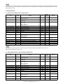
D. 20cpm/23cpm/31cpm(G) machine
(1) Europe, Eastern Europe, Russia, Australia, New Zealand
Toner cartridge
(Black)
Toner cartridge (Black toner)
x1
18K
MX-23GT-BA
Quantity in
collective package
10
Toner cartridge
(Cyan)
Toner cartridge
(Magenta)
Toner cartridge
(Yellow)
Developer (Black)
Developer
(Cyan/Magenta/
Yellow: 3 colors/set)
Drum
Toner cartridge (Cyan toner)
x1
10K
MX-23GT-CA
10
Toner cartridge (Magenta toner)
x1
10K
MX-23GT-MA
10
Toner cartridge (Yellow toner)
x1
10K
MX-23GT-YA
10
Developer (Black developer)
Developer
(Cyan/Magenta/Yellow: 3 colors/set)
(Developer (each colors))
OPC drum
x1
x1
100K
60K
MX-36GV-BA
MX-36GV-SA
10
10
x1
MX-36GR-SA
10
OPC drum unit (Process unit + OPC drum)
Color identification seal (B/C/M/Y) x 1 each
Charger cleaner
x1
x1
x1
100K (Black)
60K (Color)
100K (Black)
60K (Color)
MX-36GU-SA
10
Life
Model name
Item
Drum unit
Content
Life
Model name
Remarks
* Life: A4/Letter size at area
coverage 5%
(Reference: 15K for A4/
Letter 6%)
* Life: A4/Letter size at area
coverage 5%
* Life: A4/Letter size at area
coverage 5%
* Life: A4/Letter size at area
coverage 5%
(2) Asia, Hong Kong
Toner cartridge
(Black)
Toner cartridge (Black toner)
x1
18K
MX-23AT-BA
Quantity in
collective package
10
Toner cartridge
(Cyan)
Toner cartridge
(Magenta)
Toner cartridge
(Yellow)
Developer (Black)
Developer
(Cyan/Magenta/
Yellow: 3 colors/set)
Drum
Toner cartridge (Cyan toner)
x1
10K
MX-23AT-CA
10
Toner cartridge (Magenta toner)
x1
10K
MX-23AT-MA
10
Toner cartridge (Yellow toner)
x1
10K
MX-23AT-YA
10
Developer (Black developer)
Developer
(Cyan/Magenta/Yellow: 3 colors/set)
(Developer (each colors))
OPC drum
x1
x1
100K
60K
MX-36AV-BA
MX-36AV-SA
10
10
x1
MX-36AR-SA
10
OPC drum unit (Process unit + OPC drum)
Color identification seal (B/C/M/Y) x 1 each
Charger cleaner
x1
x1
x1
100K (Black)
60K (Color)
100K (Black)
60K (Color)
MX-36AU-SA
10
Item
Drum unit
Content
MX-3610N CONSUMABLE PARTS 2 – 3
Remarks
* Life: A4/Letter size at area
coverage 5%
(Reference: 15K for A4/
Letter 6%)
* Life: A4/Letter size at area
coverage 5%
* Life: A4/Letter size at area
coverage 5%
* Life: A4/Letter size at area
coverage 5%
(3) Middle East, Africa
Toner cartridge
(Black)
Toner cartridge (Black toner)
x1
18K
MX-23FT-BA
Quantity in
collective package
10
Toner cartridge
(Cyan)
Toner cartridge
(Magenta)
Toner cartridge
(Yellow)
Developer (Black)
Developer
(Cyan/Magenta/
Yellow: 3 colors/set)
Drum
Toner cartridge (Cyan toner)
x1
10K
MX-23FT-CA
10
Toner cartridge (Magenta toner)
x1
10K
MX-23FT-MA
10
Toner cartridge (Yellow toner)
x1
10K
MX-23FT-YA
10
Developer (Black developer)
Developer
(Cyan/Magenta/Yellow: 3 colors/set)
(Developer (each colors))
OPC drum
x1
x1
100K
60K
MX-36FV-BA
MX-36FV-SA
10
10
x1
MX-36FR-SA
10
OPC drum unit (Process unit + OPC drum)
Color identification seal (B/C/M/Y) x 1 each
Charger cleaner
x1
x1
x1
100K (Black)
60K (Color)
100K (Black)
60K (Color)
MX-36FU-SA
10
Life
Model name
Item
Drum unit
Content
Life
Model name
Remarks
* Life: A4/Letter size at area
coverage 5%
(Reference: 15K for A4/
Letter 6%)
* Life: A4/Letter size at area
coverage 5%
* Life: A4/Letter size at area
coverage 5%
* Life: A4/Letter size at area
coverage 5%
(4) Taiwan
Toner cartridge
(Black)
Toner cartridge (Black toner)
x1
18K
MX-23FT-BA
Quantity in
collective package
10
Toner cartridge
(Cyan)
Toner cartridge
(Magenta)
Toner cartridge
(Yellow)
Toner Cartridge
(Special Magenta)
Developer (Black)
Developer
(Cyan/Magenta/
Yellow: 3 colors/set)
Developer (Cyan/
Special Magenta/
Yellow: 3 colors/set)
Toner cartridge (Cyan toner)
x1
10K
MX-23FT-CA
10
Toner cartridge (Magenta toner)
x1
10K
MX-23FT-MA
10
Toner cartridge (Yellow toner)
x1
10K
MX-23FT-YA
10
Toner Cartridge (Special Magenta)
x1
10K
MX-23FT-MP
10
Developer (Black developer)
Developer
(Cyan/Magenta/Yellow: 3 colors/set)
(Developer (each colors))
Developer
(Cyan/Special Magenta/Yellow: 3 colors/set)
(Developer (each colors))
OPC drum
x1
x1
100K
60K
MX-36FV-BA
MX-36FV-SA
10
10
x1
60K
MX-23FV-SP
10
x1
MX-36FR-SA
10
OPC drum unit (Process unit + OPC drum)
Color identification seal (B/C/M/Y) x 1 each
Charger cleaner
x1
x1
x1
100K (Black)
60K (Color)
100K (Black)
60K (Color)
MX-36FU-SA
10
Item
Drum
Drum unit
Content
Remarks
* Life: A4/Letter size at area
coverage 5%
(Reference: 15K for A4/
Letter 6%)
* Life: A4/Letter size at area
coverage 5%
* Life: A4/Letter size at area
coverage 5%
* Life: A4/Letter size at area
coverage 5%
* Life: A4/Letter size at area
coverage 5%
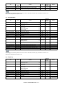
E. 26cpm/31cpm(A) machine
(1) North America, Middle America, South America (Except Brazil)
Toner cartridge
(Black)
Toner cartridge (Black toner)
x1
24K
MX-36NT-BA
Quantity in
collective package
10
Toner cartridge
(Cyan)
Toner cartridge
(Magenta)
Toner cartridge
(Yellow)
Developer (Black)
Developer
(Cyan/Magenta/
Yellow: 3 colors/set)
Toner cartridge (Cyan toner)
x1
15K
MX-36NT-CA
10
Toner cartridge (Magenta toner)
x1
15K
MX-36NT-MA
10
Toner cartridge (Yellow toner)
x1
15K
MX-36NT-YA
10
Developer (Black developer)
Developer
(Cyan/Magenta/Yellow: 3 colors/set)
(Developer (each colors))
x1
x1
100K
60K
MX-36NV-BA
MX-36NV-SA
10
10
Item
Content
Life
Model name
MX-3610N CONSUMABLE PARTS 2 – 4
Remarks
* Life: A4/Letter size at area
coverage 5%
(Reference: 20K for A4/
Letter 6%)
* Life: A4/Letter size at area
coverage 5%
* Life: A4/Letter size at area
coverage 5%
* Life: A4/Letter size at area
coverage 5%
Item
Content
Drum
OPC drum
x1
Drum unit
OPC drum unit (Process unit + OPC drum)
Color identification seal (B/C/M/Y) x 1 each
Charger cleaner
x1
x1
x1
Life
Model name
100K (Black)
60K (Color)
100K (Black)
60K (Color)
MX-36NR-SA
Quantity in
collective package
10
MX-36NU-SB
10
Remarks
(2) Europe, Eastern Europe, Russia, Australia, New Zealand
Toner cartridge
(Black)
Toner cartridge (Black toner)
x1
24K
MX-36GT-BA
Quantity in
collective package
10
Toner cartridge
(Cyan)
Toner cartridge
(Magenta)
Toner cartridge
(Yellow)
Developer (Black)
Developer
(Cyan/Magenta/
Yellow: 3 colors/set)
Drum
Toner cartridge (Cyan toner)
x1
15K
MX-36GT-CA
10
Toner cartridge (Magenta toner)
x1
15K
MX-36GT-MA
10
Toner cartridge (Yellow toner)
x1
15K
MX-36GT-YA
10
Developer (Black developer)
Developer
(Cyan/Magenta/Yellow: 3 colors/set)
(Developer (each colors))
OPC drum
x1
x1
100K
60K
MX-36GV-BA
MX-36GV-SA
10
10
x1
MX-36GR-SA
10
OPC drum unit (Process unit + OPC drum)
Color identification seal (B/C/M/Y) x 1 each
Charger cleaner
x1
x1
x1
100K (Black)
60K (Color)
100K (Black)
60K (Color)
MX-36GU-SA
10
Life
Model name
Item
Drum unit
Content
Life
Model name
Remarks
* Life: A4/Letter size at area
coverage 5%
(Reference: 20K for A4/
Letter 6%)
* Life: A4/Letter size at area
coverage 5%
* Life: A4/Letter size at area
coverage 5%
* Life: A4/Letter size at area
coverage 5%
(3) Asia, Hong Kong
Toner cartridge
(Black)
Toner cartridge (Black toner)
x1
24K
MX-36AT-BA
Quantity in
collective package
10
Toner cartridge
(Cyan)
Toner cartridge
(Magenta)
Toner cartridge
(Yellow)
Developer (Black)
Developer
(Cyan/Magenta/
Yellow: 3 colors/set)
Drum
Toner cartridge (Cyan toner)
x1
15K
MX-36AT-CA
10
Toner cartridge (Magenta toner)
x1
15K
MX-36AT-MA
10
Toner cartridge (Yellow toner)
x1
15K
MX-36AT-YA
10
Developer (Black developer)
Developer
(Cyan/Magenta/Yellow: 3 colors/set)
(Developer (each colors))
OPC drum
x1
x1
100K
60K
MX-36AV-BA
MX-36AV-SA
10
10
x1
MX-36AR-SA
10
OPC drum unit (Process unit + OPC drum)
Color identification seal (B/C/M/Y) x 1 each
Charger cleaner
x1
x1
x1
100K (Black)
60K (Color)
100K (Black)
60K (Color)
MX-36AU-SA
10
Life
Model name
Item
Drum unit
Content
Remarks
* Life: A4/Letter size at area
coverage 5%
(Reference: 20K for A4/
Letter 6%)
* Life: A4/Letter size at area
coverage 5%
* Life: A4/Letter size at area
coverage 5%
* Life: A4/Letter size at area
coverage 5%
(4) Middle East, Taiwan, Africa
Toner cartridge
(Black)
Toner cartridge (Black toner)
x1
24K
MX-36FT-BA
Quantity in
collective package
10
Toner cartridge
(Cyan)
Toner cartridge
(Magenta)
Toner cartridge
(Yellow)
Developer (Black)
Toner cartridge (Cyan toner)
x1
15K
MX-36FT-CA
10
Toner cartridge (Magenta toner)
x1
15K
MX-36FT-MA
10
Toner cartridge (Yellow toner)
x1
15K
MX-36FT-YA
10
Developer (Black developer)
x1
100K
MX-36FV-BA
10
Item
Content
MX-3610N CONSUMABLE PARTS 2 – 5
Remarks
* Life: A4/Letter size at area
coverage 5%
(Reference: 20K for A4/
Letter 6%)
* Life: A4/Letter size at area
coverage 5%
* Life: A4/Letter size at area
coverage 5%
* Life: A4/Letter size at area
coverage 5%
Developer
(Cyan/Magenta/
Yellow: 3 colors/set)
Drum
Developer
(Cyan/Magenta/Yellow: 3 colors/set)
(Developer (each colors))
OPC drum
x1
60K
MX-36FV-SA
Quantity in
collective package
10
x1
MX-36FR-SA
10
Drum unit
OPC drum unit (Process unit + OPC drum)
Color identification seal (B/C/M/Y) x 1 each
Charger cleaner
x1
x1
x1
100K (Black)
60K (Color)
100K (Black)
60K (Color)
MX-36FU-SA
10
Item
Content
Life
Model name
Remarks
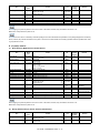
F. 36cpm machine
(1) North America, Middle America, South America (Except Brazil)
Toner cartridge
(Black)
Toner cartridge (Black toner)
x1
24K
MX-36NT-BA
Quantity in
collective package
10
Toner cartridge
(Cyan)
Toner cartridge
(Magenta)
Toner cartridge
(Yellow)
Developer (Black)
Developer
(Cyan/Magenta/
Yellow: 3 colors/set)
Drum
Toner cartridge (Cyan toner)
x1
15K
MX-36NT-CA
10
Toner cartridge (Magenta toner)
x1
15K
MX-36NT-MA
10
Toner cartridge (Yellow toner)
x1
15K
MX-36NT-YA
10
Developer (Black developer)
Developer
(Cyan/Magenta/Yellow: 3 colors/set)
(Developer (each colors))
OPC drum
x1
x1
120K
70K
MX-36NV-BA
MX-36NV-SA
10
10
x1
MX-36NR-SA
10
OPC drum unit (Process unit + OPC drum)
Color identification seal (B/C/M/Y) x 1 each
Charger cleaner
x1
x1
x1
120K (Black)
70K (Color)
120K (Black)
70K (Color)
MX-36NU-SB
10
Item
Drum unit
Content
Life
Model name
Remarks
* Life: A4/Letter size at area
coverage 5%
(Reference: 20K for A4/
Letter 6%)
* Life: A4/Letter size at area
coverage 5%
* Life: A4/Letter size at area
coverage 5%
* Life: A4/Letter size at area
coverage 5%
(2) Europe, Eastern Europe, Russia, Australia, New Zealand
Toner cartridge
(Black)
Toner cartridge (Black toner)
x1
24K
MX-36GT-BA
Quantity in
collective package
10
Toner cartridge
(Cyan)
Toner cartridge
(Magenta)
Toner cartridge
(Yellow)
Developer (Black)
Developer
(Cyan/Magenta/
Yellow: 3 colors/set)
Drum
Toner cartridge (Cyan toner)
x1
15K
MX-36GT-CA
10
Toner cartridge (Magenta toner)
x1
15K
MX-36GT-MA
10
Toner cartridge (Yellow toner)
x1
15K
MX-36GT-YA
10
Developer (Black developer)
Developer
(Cyan/Magenta/Yellow: 3 colors/set)
(Developer (each colors))
OPC drum
x1
x1
120K
70K
MX-36GV-BA
MX-36GV-SA
10
10
x1
MX-36GR-SA
10
OPC drum unit (Process unit + OPC drum)
Color identification seal (B/C/M/Y) x 1 each
Charger cleaner
x1
x1
x1
120K (Black)
70K (Color)
120K (Black)
70K (Color)
MX-36GU-SA
10
Life
Model name
Item
Drum unit
Content
Life
Model name
Remarks
* Life: A4/Letter size at area
coverage 5%
(Reference: 20K for A4/
Letter 6%)
* Life: A4/Letter size at area
coverage 5%
* Life: A4/Letter size at area
coverage 5%
* Life: A4/Letter size at area
coverage 5%
(3) Asia, Hong Kong
Toner cartridge
(Black)
Toner cartridge (Black toner)
x1
24K
MX-36AT-BA
Quantity in
collective package
10
Toner cartridge
(Cyan)
Toner cartridge
(Magenta)
Toner cartridge (Cyan toner)
x1
15K
MX-36AT-CA
10
Toner cartridge (Magenta toner)
x1
15K
MX-36AT-MA
10
Item
Content
MX-3610N CONSUMABLE PARTS 2 – 6
Remarks
* Life: A4/Letter size at area
coverage 5%
(Reference: 20K for A4/
Letter 6%)
* Life: A4/Letter size at area
coverage 5%
* Life: A4/Letter size at area
coverage 5%
Toner cartridge (Yellow toner)
x1
15K
MX-36AT-YA
Quantity in
collective package
10
Developer (Black developer)
Developer
(Cyan/Magenta/Yellow: 3 colors/set)
(Developer (each colors))
OPC drum
x1
x1
120K
70K
MX-36AV-BA
MX-36AV-SA
10
10
x1
MX-36AR-SA
10
OPC drum unit (Process unit + OPC drum)
Color identification seal (B/C/M/Y) x 1 each
Charger cleaner
x1
x1
x1
120K (Black)
70K (Color)
120K (Black)
70K (Color)
MX-36AU-SA
10
Life
Model name
Item
Toner cartridge
(Yellow)
Developer (Black)
Developer
(Cyan/Magenta/
Yellow: 3 colors/set)
Drum
Drum unit
Content
Life
Model name
Remarks
* Life: A4/Letter size at area
coverage 5%
(4) Middle East, Taiwan, Africa
Toner cartridge
(Black)
Toner cartridge (Black toner)
x1
24K
MX-36FT-BA
Quantity in
collective package
10
Toner cartridge
(Cyan)
Toner cartridge
(Magenta)
Toner cartridge
(Yellow)
Developer (Black)
Developer
(Cyan/Magenta/
Yellow: 3 colors/set)
Drum
Toner cartridge (Cyan toner)
x1
15K
MX-36FT-CA
10
Toner cartridge (Magenta toner)
x1
15K
MX-36FT-MA
10
Toner cartridge (Yellow toner)
x1
15K
MX-36FT-YA
10
Developer (Black developer)
Developer
(Cyan/Magenta/Yellow: 3 colors/set)
(Developer (each colors))
OPC drum
x1
x1
120K
70K
MX-36FV-BA
MX-36FV-SA
10
10
x1
MX-36FR-SA
10
OPC drum unit (Process unit + OPC drum)
Color identification seal (B/C/M/Y) x 1 each
Charger cleaner
x1
x1
x1
120K (Black)
70K (Color)
120K (Black)
70K (Color)
MX-36FU-SA
10
Item
Drum unit
Content
Remarks
* Life: A4/Letter size at area
coverage 5%
(Reference: 20K for A4/
Letter 6%)
* Life: A4/Letter size at area
coverage 5%
* Life: A4/Letter size at area
coverage 5%
* Life: A4/Letter size at area
coverage 5%
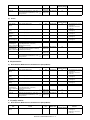
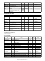
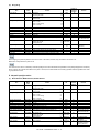
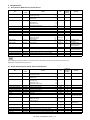
2. Maintenance parts list
A. 18cpm machine
(1) Europe, Taiwan
Item
Model
name
Upper heat roller kit
Lower heat roller kit
Fusing cleaning kit
MX-200UH
MX-200LH
MX-230CR
Primary transfer belt kit
Primary transfer blade kit
PTC kit
Secondary transfer belt kit
PS paper dust removing unit
Filter kit
Toner collection container
MX-230B1
MX-230TL
MX-230CU
MX-230B2
MX-230PD
MX-C31FL
MX-230HB
Main charger kit
MX-230MK
Staple cartridge
MX-SCX1
Finish stamp cartridge
Primary transfer belt unit
Secondary transfer belt unit
Fusing unit
Fusing unit
AR-SV1
MX-230U1
MX-230U2
MX-200FU
MX-200FU2
Content
80K
80K
80K
Quantity in
collective
package
10
10
10
80K
80K
80K
240K
80K
80K
50K
10
10
10
10
10
10
5
Black: 80K
Color: 50K
10
5000 times
x3
—
—
—
—
—
20
Life
Upper heat roller
Lower heat roller
Lower oil roller
Lower CL roller
Lower CL roller bearing
Lower CL scraper
Primary transfer belt AR
Primary transfer blade AR
PTC unit
Secondary transfer belt D3
PS paper dust removing unit
Ozone filter
Toner collection container (with LSU cleaner x 2)
x1
x1
x1
x1
x2
x1
x1
x1
x1
x1
x1
x1
x1
Main charger unit
Cleaning gum AS AR
Cleaning blade AR
Staple cartridge
x1
x1
x1
x3
Finish stamp cartridge
Primary transfer belt unit (For servicing rotation)
Secondary transfer belt unit (For servicing rotation)
Fusing unit (For servicing rotation: Heater lamp 230V)
Fusing unit (For servicing rotation: Heater lamp 110V)
x2
x1
x1
x1
x1
MX-3610N CONSUMABLE PARTS 2 – 7
20
1
1
1
1
Remarks
5% coverage for each
color; 25% color ratio
For MX-FN17
When shipping, the parts are packed in the unit of 10 sets. In the market, however, they are treated in the unit of 1 set.
Model name: Composed of the parts of 1 set
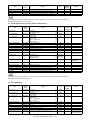
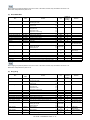
(2) Singapore, Thailand, Malaysia, India, Middle east, Other countries
Item
Model
name
Upper heat roller kit
Lower heat roller kit
Fusing cleaning kit
MX-200UH
MX-200LH
MX-230CR
Primary transfer belt kit
Primary transfer blade kit
PTC kit
Secondary transfer belt kit
PS paper dust removing unit
Filter kit
Toner collection container
MX-230B1
MX-230TL
MX-230CU
MX-230B2
MX-230PD
MX-C31FL
MX-230HB
Main charger kit
MX-230MK
Staple cartridge
Finish stamp cartridge
Primary transfer belt unit
Secondary transfer belt unit
Fusing unit
Content
80K
80K
80K
Quantity in
collective
package
10
10
10
80K
80K
80K
240K
80K
80K
50K
10
10
10
10
10
10
5
Black: 80K
Color: 50K
10
5000 times
x3
—
—
—
—
20
Life
Upper heat roller
Lower heat roller
Lower oil roller
Lower CL roller
Lower CL roller bearing
Lower CL scraper
Primary transfer belt AR
Primary transfer blade AR
PTC unit
Secondary transfer belt D3
PS paper dust removing unit
Ozone filter
Toner collection container (with LSU cleaner x 2)
x1
x1
x1
x1
x2
x1
x1
x1
x1
x1
x1
x1
x1
MX-SCX1
Main charger unit
Cleaning gum AS AR
Cleaning blade AR
Staple cartridge
x1
x1
x1
x3
AR-SV1
MX-230U1
MX-230U2
MX-200FU
Finish stamp cartridge
Primary transfer belt unit (For servicing rotation)
Secondary transfer belt unit (For servicing rotation)
Fusing unit (For servicing rotation: Heater lamp 230V)
x2
x1
x1
x1
Remarks
5% coverage for each
color; 25% color ratio
For MX-FN17
20
1
1
1
When shipping, the parts are packed in the unit of 10 sets. In the market, however, they are treated in the unit of 1 set.
Model name: Composed of the parts of 1 set
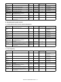
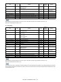
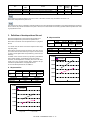
B. 20cpm machine
(1) Europe, UK, Australia, New Zealand, Taiwan
Item
Model
name
Upper heat roller kit
Lower heat roller kit
Fusing cleaning kit
MX-200UH
MX-200LH
MX-230CR
Primary transfer belt kit
Primary transfer blade kit
PTC kit
Secondary transfer belt kit
PS paper dust removing unit
Filter kit
Toner collection container
MX-230B1
MX-230TL
MX-230CU
MX-230B2
MX-230PD
MX-C31FL
MX-230HB
Main charger kit
MX-230MK
Staple cartridge
MX-SCX1
Finish stamp cartridge
Primary transfer belt unit
Secondary transfer belt unit
Fusing unit
Fusing unit
AR-SV1
MX-230U1
MX-230U2
MX-200FU
MX-200FU2
Content
100K
100K
100K
Quantity in
collective
package
10
10
10
100K
100K
100K
300K
100K
100K
50K
10
10
10
10
10
10
5
Black: 100K
Color: 60K
10
5000 times
x3
—
—
—
—
—
20
Life
Upper heat roller
Lower heat roller
Lower oil roller
Lower CL roller
Lower CL roller bearing
Lower CL scraper
Primary transfer belt AR
Primary transfer blade AR
PTC unit
Secondary transfer belt D3
PS paper dust removing unit
Ozone filter
Toner collection container (with LSU cleaner x 2)
x1
x1
x1
x1
x2
x1
x1
x1
x1
x1
x1
x1
x1
Main charger unit
Cleaning gum AS AR
Cleaning blade AR
Staple cartridge
x1
x1
x1
x3
Finish stamp cartridge
Primary transfer belt unit (For servicing rotation)
Secondary transfer belt unit (For servicing rotation)
Fusing unit (For servicing rotation: Heater lamp 230V)
Fusing unit (For servicing rotation: Heater lamp 110V)
x2
x1
x1
x1
x1
MX-3610N CONSUMABLE PARTS 2 – 8
20
1
1
1
1
Remarks
5% coverage for each
color; 25% color ratio
For MX-FN17
When shipping, the parts are packed in the unit of 10 sets. In the market, however, they are treated in the unit of 1 set.
Model name: Composed of the parts of 1 set
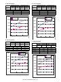
(2) Singapore, Thailand, Malaysia, India, Middle east, Other countries
Item
Model
name
Upper heat roller kit
Lower heat roller kit
Fusing cleaning kit
MX-200UH
MX-200LH
MX-230CR
Primary transfer belt kit
Primary transfer blade kit
PTC kit
Secondary transfer belt kit
PS paper dust removing unit
Filter kit
Toner collection container
MX-230B1
MX-230TL
MX-230CU
MX-230B2
MX-230PD
MX-C31FL
MX-230HB
Main charger kit
MX-230MK
Staple cartridge
MX-SCX1
Finish stamp cartridge
Primary transfer belt unit
Secondary transfer belt unit
Fusing unit
Fusing unit
AR-SV1
MX-230U1
MX-230U2
MX-200FU1
MX-200FU
Content
100K
100K
100K
Quantity in
collective
package
10
10
10
100K
100K
100K
300K
100K
100K
50K
10
10
10
10
10
10
5
Black: 100K
Color: 60K
10
5000 times
x3
—
—
—
—
—
20
Life
Upper heat roller
Lower heat roller
Lower oil roller
Lower CL roller
Lower CL roller bearing
Lower CL scraper
Primary transfer belt AR
Primary transfer blade AR
PTC unit
Secondary transfer belt D3
PS paper dust removing unit
Ozone filter
Toner collection container (with LSU cleaner x 2)
x1
x1
x1
x1
x2
x1
x1
x1
x1
x1
x1
x1
x1
Main charger unit
Cleaning gum AS AR
Cleaning blade AR
Staple cartridge
x1
x1
x1
x3
Finish stamp cartridge
Primary transfer belt unit (For servicing rotation)
Secondary transfer belt unit (For servicing rotation)
Fusing unit (For servicing rotation: Heater lamp 120V)
Fusing unit (For servicing rotation: Heater lamp 230V)
x2
x1
x1
x1
x1
Remarks
5% coverage for each
color; 25% color ratio
For MX-FN17
20
1
1
1
1
When shipping, the parts are packed in the unit of 10 sets. In the market, however, they are treated in the unit of 1 set.
Model name: Composed of the parts of 1 set
(3) Hong Kong
Item
Model
name
Upper heat roller kit
Lower heat roller kit
Fusing cleaning kit
MX-200UH
MX-200LH
MX-230CR
Primary transfer belt kit
Primary transfer blade kit
PTC kit
Secondary transfer belt kit
PS paper dust removing unit
Filter kit
Toner collection container
MX-230B1
MX-230TL
MX-230CU
MX-230B2
MX-230PD
MX-C31FL
MX-230HB
Main charger kit
MX-230MK
Staple cartridge
Finish stamp cartridge
Primary transfer belt unit
Secondary transfer belt unit
Fusing unit
Content
100K
100K
100K
Quantity in
collective
package
10
10
10
100K
100K
100K
300K
100K
100K
50K
10
10
10
10
10
10
5
Black: 100K
Color: 60K
10
5000 times
x3
—
—
—
—
20
Life
Upper heat roller
Lower heat roller
Lower oil roller
Lower CL roller
Lower CL roller bearing
Lower CL scraper
Primary transfer belt AR
Primary transfer blade AR
PTC unit
Secondary transfer belt D3
PS paper dust removing unit
Ozone filter
Toner collection container (with LSU cleaner x 2)
x1
x1
x1
x1
x2
x1
x1
x1
x1
x1
x1
x1
x1
MX-SCX1
Main charger unit
Cleaning gum AS AR
Cleaning blade AR
Staple cartridge
x1
x1
x1
x3
AR-SV1
MX-230U1
MX-230U2
MX-200FU
Finish stamp cartridge
Primary transfer belt unit (For servicing rotation)
Secondary transfer belt unit (For servicing rotation)
Fusing unit (For servicing rotation: Heater lamp 230V)
x2
x1
x1
x1
20
1
1
1
When shipping, the parts are packed in the unit of 10 sets. In the market, however, they are treated in the unit of 1 set.
Model name: Composed of the parts of 1 set
MX-3610N CONSUMABLE PARTS 2 – 9
Remarks
5% coverage for each
color; 25% color ratio
For MX-FN17
The numbers in the column of "Quantity in collective package" in the above list indicate the quantities for one package shipped from the factory.
Since, however, the products are treated as one piece or one set, their model names and necessary quantities must be specified when ordering. Pay attention to that.
C. 23cpm machine
(1) North America, Middle America, South America
Item
Model
name
Fusing belt kit
MX-230FB
Pressure roller kit
MX-230LH
Fusing cleaning kit
MX-230CR
Primary transfer belt kit
Primary transfer blade kit
PTC kit
Secondary transfer belt kit
PS paper dust removing unit
Filter kit
Toner collection container
MX-230B1
MX-230TL
MX-230CU
MX-230B2
MX-230PD
MX-C31FL
MX-230HB
Main charger kit
MX-230MK
Staple cartridge
MX-SCX1
Finish stamp cartridge
Primary transfer belt unit
Secondary transfer belt unit
Fusing unit
Fusing unit
AR-SV1
MX-230U1
MX-230U2
MX-230FU1
MX-230FU
Content
100K
Quantity in
collective
package
10
200K
10
100K
10
100K
100K
100K
300K
100K
100K
50K
10
10
10
10
10
10
5
Black: 100K
Color: 60K
10
5000 times
x3
—
—
—
—
—
20
Life
Fusing belt
Fuser belt guide collar
Fusing roller
Pressure roller
Lower oil roller
Lower CL roller
Lower CL roller bearing
Lower CL scraper
Primary transfer belt AR
Primary transfer blade AR
PTC unit
Secondary transfer belt D3
PS paper dust removing unit
Ozone filter
Toner collection container (with LSU cleaner x 2)
x1
x2
x1
x1
x1
x1
x2
x1
x1
x1
x1
x1
x1
x1
x1
Main charger unit
Cleaning gum AS AR
Cleaning blade AR
Staple cartridge
x1
x1
x1
x3
Finish stamp cartridge
Primary transfer belt unit (For servicing rotation)
Secondary transfer belt unit (For servicing rotation)
Fusing unit (For servicing rotation: Heater lamp 120V)
Fusing unit (For servicing rotation: Heater lamp 230V)
x2
x1
x1
x1
x1
Remarks
5% coverage for each
color; 25% color ratio
For inner finisher
(MX-FN17)
20
1
1
1
1
When shipping, the parts are packed in the unit of 10 sets. In the market, however, they are treated in the unit of 1 set.
Model name: Composed of the parts of 1 set
(2) Europe, Eastern Europe, Russia, Australia, New Zealand
Item
Model
name
Fusing belt kit
MX-230FB
Pressure roller kit
MX-230LH
Fusing cleaning kit
MX-230CR
Primary transfer belt kit
Primary transfer blade kit
PTC kit
Secondary transfer belt kit
PS paper dust removing unit
Filter kit
Toner collection container
MX-230B1
MX-230TL
MX-230CU
MX-230B2
MX-230PD
MX-C31FL
MX-230HB
Main charger kit
MX-230MK
Staple cartridge
Finish stamp cartridge
Content
100K
Quantity in
collective
package
10
200K
10
100K
10
100K
100K
100K
300K
100K
100K
50K
10
10
10
10
10
10
5
Black: 100K
Color: 60K
10
5000 times
x3
—
20
Life
Fusing belt
Fuser belt guide collar
Fusing roller
Pressure roller
Lower oil roller
Lower CL roller
Lower CL roller bearing
Lower CL scraper
Primary transfer belt AR
Primary transfer blade AR
PTC unit
Secondary transfer belt D3
PS paper dust removing unit
Ozone filter
Toner collection container (with LSU cleaner x 2)
x1
x2
x1
x1
x1
x1
x2
x1
x1
x1
x1
x1
x1
x1
x1
MX-SCX1
Main charger unit
Cleaning gum AS AR
Cleaning blade AR
Staple cartridge
x1
x1
x1
x3
AR-SV1
Finish stamp cartridge
x2
MX-3610N CONSUMABLE PARTS 2 – 10
20
Remarks
5% coverage for each
color; 25% color ratio
For MX-FN17
Item
Model
name
Primary transfer belt unit
Secondary transfer belt unit
Fusing unit
MX-230U1
MX-230U2
MX-230FU
Content
Primary transfer belt unit (For servicing rotation)
Secondary transfer belt unit (For servicing rotation)
Fusing unit (For servicing rotation: Heater lamp 230V)
Life
x1
x1
x1
—
—
—
Quantity in
collective
package
1
1
1
Remarks
When shipping, the parts are packed in the unit of 10 sets. In the market, however, they are treated in the unit of 1 set.
Model name: Composed of the parts of 1 set
(3) Asia, Middle East
Item
Model
name
Fusing belt kit
MX-230FB
Pressure roller kit
MX-230LH
Fusing cleaning kit
MX-230CR
Primary transfer belt kit
Primary transfer blade kit
PTC kit
Secondary transfer belt kit
PS paper dust removing unit
Filter kit
Toner collection container
MX-230B1
MX-230TL
MX-230CU
MX-230B2
MX-230PD
MX-C31FL
MX-230HB
Main charger kit
MX-230MK
Staple cartridge
MX-SCX1
Finish stamp cartridge
Primary transfer belt unit
Secondary transfer belt unit
Fusing unit
Fusing unit
AR-SV1
MX-230U1
MX-230U2
MX-230FU1
MX-230FU
Content
100K
Quantity in
collective
package
10
200K
10
100K
10
100K
100K
100K
300K
100K
100K
50K
10
10
10
10
10
10
5
Black: 100K
Color: 60K
10
5000 times
x3
—
—
—
—
—
20
Life
Fusing belt
Fuser belt guide collar
Fusing roller
Pressure roller
Lower oil roller
Lower CL roller
Lower CL roller bearing
Lower CL scraper
Primary transfer belt AR
Primary transfer blade AR
PTC unit
Secondary transfer belt D3
PS paper dust removing unit
Ozone filter
Toner collection container (with LSU cleaner x 2)
x1
x2
x1
x1
x1
x1
x2
x1
x1
x1
x1
x1
x1
x1
x1
Main charger unit
Cleaning gum AS AR
Cleaning blade AR
Staple cartridge
x1
x1
x1
x3
Finish stamp cartridge
Primary transfer belt unit (For servicing rotation)
Secondary transfer belt unit (For servicing rotation)
Fusing unit (For servicing rotation: Heater lamp 120V)
Fusing unit (For servicing rotation: Heater lamp 230V)
x2
x1
x1
x1
x1
Remarks
5% coverage for each
color; 25% color ratio
For MX-FN17
20
1
1
1
1
When shipping, the parts are packed in the unit of 10 sets. In the market, however, they are treated in the unit of 1 set.
Model name: Composed of the parts of 1 set
(4) Hong Kong
Item
Model
name
Fusing belt kit
MX-230FB
Pressure roller kit
MX-230LH
Fusing cleaning kit
MX-230CR
Primary transfer belt kit
Primary transfer blade kit
PTC kit
Secondary transfer belt kit
PS paper dust removing unit
Filter kit
Toner collection container
MX-230B1
MX-230TL
MX-230CU
MX-230B2
MX-230PD
MX-C31FL
MX-230HB
Content
Fusing belt
Fuser belt guide collar
Fusing roller
Pressure roller
Lower oil roller
Lower CL roller
Lower CL roller bearing
Lower CL scraper
Primary transfer belt AR
Primary transfer blade AR
PTC unit
Secondary transfer belt D3
PS paper dust removing unit
Ozone filter
Toner collection container (with LSU cleaner x 2)
100K
Quantity in
collective
package
10
200K
10
100K
10
100K
100K
100K
300K
100K
100K
50K
10
10
10
10
10
10
5
Life
x1
x2
x1
x1
x1
x1
x2
x1
x1
x1
x1
x1
x1
x1
x1
MX-3610N CONSUMABLE PARTS 2 – 11
Remarks
5% coverage for each
color; 25% color ratio
Model
name
Item
Main charger kit
MX-230MK
Staple cartridge
Finish stamp cartridge
Primary transfer belt unit
Secondary transfer belt unit
Fusing unit
Content
Life
MX-SCX1
Main charger unit
Cleaning gum AS AR
Cleaning blade AR
Staple cartridge
x1
x1
x1
x3
AR-SV1
MX-230U1
MX-230U2
MX-230FU
Finish stamp cartridge
Primary transfer belt unit (For servicing rotation)
Secondary transfer belt unit (For servicing rotation)
Fusing unit (For servicing rotation: Heater lamp 230V)
x2
x1
x1
x1
Black: 100K
Color: 60K
5000 times
x3
—
—
—
—
Quantity in
collective
package
10
20
Remarks
For MX-FN17
20
1
1
1
When shipping, the parts are packed in the unit of 10 sets. In the market, however, they are treated in the unit of 1 set.
Model name: Composed of the parts of 1 set
The numbers in the column of "Quantity in collective package" in the above list indicate the quantities for one package shipped from the factory.
Since, however, the products are treated as one piece or one set, their model names and necessary quantities must be specified when ordering. Pay attention to that.
D. 31cpm(G) machine
(1) North America, Middle America, South America
Item
Model
name
Fusing belt kit
MX-360FB
Pressure roller kit
MX-230LH
Fusing cleaning kit
MX-260CR
Primary transfer belt kit
Primary transfer blade kit
PTC kit
Secondary transfer belt kit
PS paper dust removing unit
Filter kit
Main charger kit
MX-230B1
MX-230TL
MX-230CU
MX-230B2
MX-230PD
MX-C31FL
MX-360MK
Staple cartridge
200K
Quantity in
collective
package
10
200K
10
100K
10
100K
100K
100K
300K
100K
100K
Black: 100K
Color: 60K
10
10
10
10
10
10
10
20
x2
x1
5000 times
x3
—
50K
x1
x1
x1
—
—
—
1
1
1
Content
Life
MX-SCX1
Fusing belt
Fuser belt guide collar
Fusing roller
Pressure roller
Lower oil roller
Lower CL roller
Lower CL roller bearing
Lower CL scraper
Primary transfer belt AR
Primary transfer blade AR
PTC unit
Secondary transfer belt D3
PS paper dust removing unit
Ozone filter
Main charger unit
Cleaning gum AS AR
Cleaning blade AR
Staple cartridge
x1
x2
x1
x1
x1
x1
x2
x1
x1
x1
x1
x1
x1
x1
x1
x1
x1
x3
Finish stamp cartridge
Toner collection container
AR-SV1
MX-230HB
Finish stamp cartridge
Toner collection container (with LSU cleaner x 2)
Primary transfer belt unit
Secondary transfer belt unit
Fusing unit
MX-230U1
MX-230U2
MX-260FU1
Primary transfer belt unit (For servicing rotation)
Secondary transfer belt unit (For servicing rotation)
Fusing unit (For servicing rotation: Heater lamp 120V)
20
5
Remarks
For inner finisher
(MX-FN17)
5% coverage for each
color; 25% color ratio
When shipping, the parts are packed in the unit of 10 sets. In the market, however, they are treated in the unit of 1 set.
Model name: Composed of the parts of 1 set
(2) Europe, Eastern Europe, Russia, Australia, New Zealand
Item
Model
name
Fusing belt kit
MX-360FB
Pressure roller kit
MX-230LH
Content
Fusing belt
Fuser belt guide collar
Fusing roller
Pressure roller
200K
Quantity in
collective
package
10
200K
10
Life
x1
x2
x1
x1
MX-3610N CONSUMABLE PARTS 2 – 12
Remarks
Item
Model
name
Fusing cleaning kit
MX-230CR
Primary transfer belt kit
Primary transfer blade kit
PTC kit
Secondary transfer belt kit
PS paper dust removing unit
Filter kit
Toner collection container
MX-230B1
MX-230TL
MX-230CU
MX-230B2
MX-230PD
MX-C31FL
MX-230HB
Main charger kit
MX-230MK
Staple cartridge
MX-SCX1
Finish stamp cartridge
Primary transfer belt unit
Secondary transfer belt unit
Fusing unit
Fusing unit
AR-SV1
MX-230U1
MX-230U2
MX-260FU
MX-260FU2
Content
100K
Quantity in
collective
package
10
100K
100K
100K
300K
100K
100K
50K
10
10
10
10
10
10
5
Black: 100K
Color: 60K
10
5000 times
x3
—
—
—
—
—
20
Life
Lower oil roller
Lower CL roller
Lower CL roller bearing
Lower CL scraper
Primary transfer belt AR
Primary transfer blade AR
PTC unit
Secondary transfer belt D3
PS paper dust removing unit
Ozone filter
Toner collection container (with LSU cleaner x 2)
x1
x1
x2
x1
x1
x1
x1
x1
x1
x1
x1
Main charger unit
Cleaning gum AS AR
Cleaning blade AR
Staple cartridge
x1
x1
x1
x3
Finish stamp cartridge
Primary transfer belt unit (For servicing rotation)
Secondary transfer belt unit (For servicing rotation)
Fusing unit (For servicing rotation: Heater lamp 230V)
Fusing unit (For servicing rotation: Heater lamp 110V)
x2
x1
x1
x1
x1
Remarks
5% coverage for each
color; 25% color ratio
For inner finisher
(MX-FN17)
20
1
1
1
1
When shipping, the parts are packed in the unit of 10 sets. In the market, however, they are treated in the unit of 1 set.
Model name: Composed of the parts of 1 set
(3) Asia, Middle East
Item
Model
name
Fusing belt kit
MX-360FB
Pressure roller kit
MX-230LH
Fusing cleaning kit
MX-230CR
Primary transfer belt kit
Primary transfer blade kit
PTC kit
Secondary transfer belt kit
PS paper dust removing unit
Filter kit
Toner collection container
MX-230B1
MX-230TL
MX-230CU
MX-230B2
MX-230PD
MX-C31FL
MX-230HB
Main charger kit
MX-230MK
Staple cartridge
Finish stamp cartridge
Primary transfer belt unit
Secondary transfer belt unit
Fusing unit
Content
200K
Quantity in
collective
package
10
200K
10
100K
10
100K
100K
100K
300K
100K
100K
50K
10
10
10
10
10
10
5
Black: 100K
Color: 60K
10
5000 times
x3
—
—
—
—
20
Life
Fusing belt
Fuser belt guide collar
Fusing roller
Pressure roller
Lower oil roller
Lower CL roller
Lower CL roller bearing
Lower CL scraper
Primary transfer belt AR
Primary transfer blade AR
PTC unit
Secondary transfer belt D3
PS paper dust removing unit
Ozone filter
Toner collection container (with LSU cleaner x 2)
x1
x2
x1
x1
x1
x1
x2
x1
x1
x1
x1
x1
x1
x1
x1
MX-SCX1
Main charger unit
Cleaning gum AS AR
Cleaning blade AR
Staple cartridge
x1
x1
x1
x3
AR-SV1
MX-230U1
MX-230U2
MX-260FU
Finish stamp cartridge
Primary transfer belt unit (For servicing rotation)
Secondary transfer belt unit (For servicing rotation)
Fusing unit (For servicing rotation: Heater lamp 230V)
x2
x1
x1
x1
20
1
1
1
When shipping, the parts are packed in the unit of 10 sets. In the market, however, they are treated in the unit of 1 set.
Model name: Composed of the parts of 1 set
MX-3610N CONSUMABLE PARTS 2 – 13
Remarks
5% coverage for each
color; 25% color ratio
For inner finisher
(MX-FN17)
(4) Hong Kong
Item
Model
name
Fusing belt kit
MX-360FB
Pressure roller kit
MX-230LH
Fusing cleaning kit
MX-230CR
Primary transfer belt kit
Primary transfer blade kit
PTC kit
Secondary transfer belt kit
PS paper dust removing unit
Filter kit
Toner collection container
MX-230B1
MX-230TL
MX-230CU
MX-230B2
MX-230PD
MX-C31FL
MX-230HB
Main charger kit
MX-230MK
Staple cartridge
Finish stamp cartridge
Primary transfer belt unit
Secondary transfer belt unit
Fusing unit
Content
200K
Quantity in
collective
package
10
200K
10
100K
10
100K
100K
100K
300K
100K
100K
50K
10
10
10
10
10
10
5
Black: 100K
Color: 60K
10
5000 times
x3
—
—
—
—
20
Life
Fusing belt
Fuser belt guide collar
Fusing roller
Pressure roller
Lower oil roller
Lower CL roller
Lower CL roller bearing
Lower CL scraper
Primary transfer belt AR
Primary transfer blade AR
PTC unit
Secondary transfer belt D3
PS paper dust removing unit
Ozone filter
Toner collection container (with LSU cleaner x 2)
x1
x2
x1
x1
x1
x1
x2
x1
x1
x1
x1
x1
x1
x1
x1
MX-SCX1
Main charger unit
Cleaning gum AS AR
Cleaning blade AR
Staple cartridge
x1
x1
x1
x3
AR-SV1
MX-230U1
MX-230U2
MX-260FU
Finish stamp cartridge
Primary transfer belt unit (For servicing rotation)
Secondary transfer belt unit (For servicing rotation)
Fusing unit (For servicing rotation: Heater lamp 230V)
x2
x1
x1
x1
Remarks
5% coverage for each
color; 25% color ratio
For inner finisher
(MX-FN17)
20
1
1
1
When shipping, the parts are packed in the unit of 10 sets. In the market, however, they are treated in the unit of 1 set.
Model name: Composed of the parts of 1 set
The numbers in the column of "Quantity in collective package" in the above list indicate the quantities for one package shipped from the factory.
Since, however, the products are treated as one piece or one set, their model names and necessary quantities must be specified when ordering. Pay attention to that.
E. 26cpm/31cpm(A) machine
(1) North America, Middle America, South America
Item
Model
name
Fusing belt kit
MX-360FB
Pressure roller kit
MX-230LH
Fusing cleaning kit
MX-230CR
Primary transfer belt kit
Primary transfer blade kit
PTC kit
Secondary transfer belt kit
PS paper dust removing unit
Filter kit
Toner collection container
MX-230B1
MX-230TL
MX-230CU
MX-230B2
MX-230PD
MX-C31FL
MX-230HB
Main charger kit
MX-360MK
Staple cartridge
AR-SC3
Staple cartridge
MX-SCX1
Finish stamp cartridge
AR-SV1
Content
200K
Quantity in
collective
package
10
200K
10
100K
10
100K
100K
100K
300K
100K
100K
50K
10
10
10
10
10
10
5
Black: 100K
Color: 60K
10
2000 times
x3
5000 times
x3
40
—
20
Life
Fusing belt
Fuser belt guide collar
Fusing roller
Pressure roller
Lower oil roller
Lower CL roller
Lower CL roller bearing
Lower CL scraper
Primary transfer belt AR
Primary transfer blade AR
PTC unit
Secondary transfer belt D3
PS paper dust removing unit
Ozone filter
Toner collection container (with LSU cleaner x 2)
x1
x2
x1
x1
x1
x1
x2
x1
x1
x1
x1
x1
x1
x1
x1
Main charger unit
Cleaning gum AS AR
Cleaning blade AR
Staple cartridge
x1
x1
x1
x3
Staple cartridge
x3
Finish stamp cartridge
x2
MX-3610N CONSUMABLE PARTS 2 – 14
20
Remarks
5% coverage for each
color; 25% color ratio
For saddle finisher
(MX-FN10)
For saddle finisher
(MX-FN10) and inner
finisher (MX-FN17)
Item
Model
name
Primary transfer belt unit
Secondary transfer belt unit
Fusing unit
Fusing unit
MX-230U1
MX-230U2
MX-260FU1
MX-260FU
Content
Primary transfer belt unit (For servicing rotation)
Secondary transfer belt unit (For servicing rotation)
Fusing unit (For servicing rotation: Heater lamp 120V)
Fusing unit (For servicing rotation: Heater lamp 230V)
Life
x1
x1
x1
x1
—
—
—
—
Quantity in
collective
package
1
1
1
1
Remarks
When shipping, the parts are packed in the unit of 10 sets. In the market, however, they are treated in the unit of 1 set.
Model name: Composed of the parts of 1 set
(2) Europe, Eastern Europe, Russia, Australia, New Zealand
Item
Model
name
Fusing belt kit
MX-360FB
Pressure roller kit
MX-230LH
Fusing cleaning kit
MX-230CR
Primary transfer belt kit
Primary transfer blade kit
PTC kit
Secondary transfer belt kit
PS paper dust removing unit
Filter kit
Toner collection container
MX-230B1
MX-230TL
MX-230CU
MX-230B2
MX-230PD
MX-C31FL
MX-230HB
Main charger kit
MX-230MK
Staple cartridge
AR-SC3
Staple cartridge
MX-SCX1
Finish stamp cartridge
Primary transfer belt unit
Secondary transfer belt unit
Fusing unit
Fusing unit
AR-SV1
MX-230U1
MX-230U2
MX-260FU
MX-260FU2
Content
200K
Quantity in
collective
package
10
200K
10
100K
10
100K
100K
100K
300K
100K
100K
50K
10
10
10
10
10
10
5
Black: 100K
Color: 60K
10
2000 times
x3
5000 times
x3
—
—
—
—
—
40
Life
Fusing belt
Fuser belt guide collar
Fusing roller
Pressure roller
Lower oil roller
Lower CL roller
Lower CL roller bearing
Lower CL scraper
Primary transfer belt AR
Primary transfer blade AR
PTC unit
Secondary transfer belt D3
PS paper dust removing unit
Ozone filter
Toner collection container (with LSU cleaner x 2)
x1
x2
x1
x1
x1
x1
x2
x1
x1
x1
x1
x1
x1
x1
x1
Main charger unit
Cleaning gum AS AR
Cleaning blade AR
Staple cartridge
x1
x1
x1
x3
Staple cartridge
x3
Finish stamp cartridge
Primary transfer belt unit (For servicing rotation)
Secondary transfer belt unit (For servicing rotation)
Fusing unit (For servicing rotation: Heater lamp 230V)
Fusing unit (For servicing rotation: Heater lamp 110V)
x2
x1
x1
x1
x1
20
Remarks
5% coverage for each
color; 25% color ratio
For MX-FN10
(saddle staple)
For MX-FN10/FN17
20
1
1
1
1
When shipping, the parts are packed in the unit of 10 sets. In the market, however, they are treated in the unit of 1 set.
Model name: Composed of the parts of 1 set
(3) Asia, Middle East
Item
Model
name
Fusing belt kit
MX-360FB
Pressure roller kit
MX-230LH
Fusing cleaning kit
MX-230CR
Primary transfer belt kit
Primary transfer blade kit
PTC kit
Secondary transfer belt kit
PS paper dust removing unit
Filter kit
Toner collection container
MX-230B1
MX-230TL
MX-230CU
MX-230B2
MX-230PD
MX-C31FL
MX-230HB
Content
Fusing belt
Fuser belt guide collar
Fusing roller
Pressure roller
Lower oil roller
Lower CL roller
Lower CL roller bearing
Lower CL scraper
Primary transfer belt AR
Primary transfer blade AR
PTC unit
Secondary transfer belt D3
PS paper dust removing unit
Ozone filter
Toner collection container (with LSU cleaner x 2)
200K
Quantity in
collective
package
10
200K
10
100K
10
100K
100K
100K
300K
100K
100K
50K
10
10
10
10
10
10
5
Life
x1
x2
x1
x1
x1
x1
x2
x1
x1
x1
x1
x1
x1
x1
x1
MX-3610N CONSUMABLE PARTS 2 – 15
Remarks
5% coverage for each
color; 25% color ratio
Item
Model
name
Main charger kit
MX-230MK
Staple cartridge
AR-SC3
Staple cartridge
MX-SCX1
Finish stamp cartridge
Primary transfer belt unit
Secondary transfer belt unit
Fusing unit
Fusing unit
AR-SV1
MX-230U1
MX-230U2
MX-260FU1
MX-260FU
Content
Life
Main charger unit
Cleaning gum AS AR
Cleaning blade AR
Staple cartridge
x1
x1
x1
x3
Staple cartridge
x3
Finish stamp cartridge
Primary transfer belt unit (For servicing rotation)
Secondary transfer belt unit (For servicing rotation)
Fusing unit (For servicing rotation: Heater lamp 120V)
Fusing unit (For servicing rotation: Heater lamp 230V)
x2
x1
x1
x1
x1
Black: 100K
Color: 60K
2000 times
x3
5000 times
x3
—
—
—
—
—
Quantity in
collective
package
10
40
20
Remarks
For MX-FN10
(saddle staple)
For MX-FN10/FN17
20
1
1
1
1
When shipping, the parts are packed in the unit of 10 sets. In the market, however, they are treated in the unit of 1 set.
Model name: Composed of the parts of 1 set
(4) Hong Kong
Item
Model
name
Fusing belt kit
MX-360FB
Pressure roller kit
MX-230LH
Fusing cleaning kit
MX-230CR
Primary transfer belt kit
Primary transfer blade kit
PTC kit
Secondary transfer belt kit
PS paper dust removing unit
Filter kit
Toner collection container
MX-230B1
MX-230TL
MX-230CU
MX-230B2
MX-230PD
MX-C31FL
MX-230HB
Main charger kit
MX-230MK
Staple cartridge
AR-SC3
Staple cartridge
Finish stamp cartridge
Primary transfer belt unit
Secondary transfer belt unit
Fusing unit
Content
200K
Quantity in
collective
package
10
200K
10
100K
10
100K
100K
100K
300K
100K
100K
50K
10
10
10
10
10
10
5
Black: 100K
Color: 60K
10
2000 times
x3
5000 times
x3
—
—
—
—
40
Life
Fusing belt
Fuser belt guide collar
Fusing roller
Pressure roller
Lower oil roller
Lower CL roller
Lower CL roller bearing
Lower CL scraper
Primary transfer belt AR
Primary transfer blade AR
PTC unit
Secondary transfer belt D3
PS paper dust removing unit
Ozone filter
Toner collection container (with LSU cleaner x 2)
x1
x2
x1
x1
x1
x1
x2
x1
x1
x1
x1
x1
x1
x1
x1
Main charger unit
Cleaning gum AS AR
Cleaning blade AR
Staple cartridge
x1
x1
x1
x3
MX-SCX1
Staple cartridge
x3
AR-SV1
MX-230U1
MX-230U2
MX-260FU
Finish stamp cartridge
Primary transfer belt unit (For servicing rotation)
Secondary transfer belt unit (For servicing rotation)
Fusing unit (For servicing rotation: Heater lamp 230V)
x2
x1
x1
x1
20
Remarks
5% coverage for each
color; 25% color ratio
For MX-FN10
(saddle staple)
For MX-FN10/FN17
20
1
1
1
When shipping, the parts are packed in the unit of 10 sets. In the market, however, they are treated in the unit of 1 set.
Model name: Composed of the parts of 1 set
The numbers in the column of "Quantity in collective package" in the above list indicate the quantities for one package shipped from the factory.
Since, however, the products are treated as one piece or one set, their model names and necessary quantities must be specified when ordering. Pay attention to that.
MX-3610N CONSUMABLE PARTS 2 – 16
F. 36cpm machine
(1) North America, Middle America, South America
Item
Model
name
Fusing belt kit
MX-360FB
Pressure roller kit
MX-230LH
Web cleaning kit
MX-360WB
Primary transfer belt kit
Primary transfer blade kit
PTC kit
Secondary transfer belt kit
PS paper dust removing unit
Filter kit
Main charger kit
MX-230B1
MX-230TL
MX-230CU
MX-230B2
MX-230PD
MX-C31FL
MX-360MK
Content
240K
Quantity in
collective
package
10
240K
10
120K
10
120K
120K
120K
360K
120K
120K
Black: 120K
Color: 70K
10
10
10
10
10
10
10
2000 times
x3
5000 times
x3
40
Life
Fusing belt
Fuser belt guide collar
Fusing roller
Pressure roller
Web roller
Web guide shaft
Web pressure roller
Web pressure roller bearing
Primary transfer belt AR
Primary transfer blade AR
PTC unit
Secondary transfer belt D3
PS paper dust removing unit
Ozone filter
Main charger unit
Cleaning gum AS AR
Cleaning blade AR
Staple cartridge
x1
x2
x1
x1
x1
x2
x1
x2
x1
x1
x1
x1
x1
x1
x1
x1
x1
x3
Staple cartridge
AR-SC3
Staple cartridge
MX-SCX1
Staple cartridge
x3
Finish stamp cartridge
Toner collection container
AR-SV1
MX-230HB
Finish stamp cartridge
Toner collection container (with LSU cleaner x 2)
x2
x1
—
50K
20
5
Primary transfer belt unit
Secondary transfer belt unit
Fusing unit
MX-230U1
MX-230U2
MX-360FU1
Primary transfer belt unit (For servicing rotation)
Secondary transfer belt unit (For servicing rotation)
Fusing unit (For servicing rotation: Heater lamp 120V)
x1
x1
x1
—
—
—
1
1
1
20
Remarks
For saddle finisher
(MX-FN10)
For saddle finisher
(MX-FN10) and inner
finisher (MX-FN17)
5% coverage for each
color; 25% color ratio
When shipping, the parts are packed in the unit of 10 sets. In the market, however, they are treated in the unit of 1 set.
Model name: Composed of the parts of 1 set
(2) Europe, Eastern Europe, Russia, Australia, New Zealand
Item
Model
name
Fusing belt kit
MX-360FB
Pressure roller kit
MX-230LH
Web cleaning kit
MX-360WB
Primary transfer belt kit
Primary transfer blade kit
PTC kit
Secondary transfer belt kit
PS paper dust removing unit
Filter kit
Toner collection container
MX-230B1
MX-230TL
MX-230CU
MX-230B2
MX-230PD
MX-C31FL
MX-230HB
Main charger kit
MX-230MK
Staple cartridge
AR-SC3
Staple cartridge
Finish stamp cartridge
Primary transfer belt unit
Secondary transfer belt unit
Fusing unit
Content
240K
Quantity in
collective
package
10
240K
10
120K
10
120K
120K
120K
360K
120K
120K
50K
10
10
10
10
10
10
5
Black: 120K
Color: 70K
10
2000 times
x3
5000 times
x3
—
—
—
—
40
Life
Fusing belt
Fuser belt guide collar
Fusing roller
Pressure roller
Web roller
Web guide shaft
Web pressure roller
Web pressure roller bearing
Primary transfer belt AR
Primary transfer blade AR
PTC unit
Secondary transfer belt D3
PS paper dust removing unit
Ozone filter
Toner collection container (with LSU cleaner x 2)
x1
x2
x1
x1
x1
x2
x1
x2
x1
x1
x1
x1
x1
x1
x1
Main charger unit
Cleaning gum AS AR
Cleaning blade AR
Staple cartridge
x1
x1
x1
x3
MX-SCX1
Staple cartridge
x3
AR-SV1
MX-230U1
MX-230U2
MX-360FU
Finish stamp cartridge
Primary transfer belt unit (For servicing rotation)
Secondary transfer belt unit (For servicing rotation)
Fusing unit (For servicing rotation: Heater lamp 230V)
x2
x1
x1
x1
MX-3610N CONSUMABLE PARTS 2 – 17
20
20
1
1
1
Remarks
5% coverage for each
color; 25% color ratio
For MX-FN10
(saddle staple)
For MX-FN10/FN17
When shipping, the parts are packed in the unit of 10 sets. In the market, however, they are treated in the unit of 1 set.
Model name: Composed of the parts of 1 set
(3) Asia, Middle East
Item
Model
name
Fusing belt kit
MX-360FB
Pressure roller kit
MX-230LH
Web cleaning kit
MX-360WB
Primary transfer belt kit
Primary transfer blade kit
PTC kit
Secondary transfer belt kit
PS paper dust removing unit
Filter kit
Toner collection container
MX-230B1
MX-230TL
MX-230CU
MX-230B2
MX-230PD
MX-C31FL
MX-230HB
Main charger kit
MX-230MK
Staple cartridge
AR-SC3
Staple cartridge
Finish stamp cartridge
Primary transfer belt unit
Secondary transfer belt unit
Fusing unit
Content
240K
Quantity in
collective
package
10
240K
10
120K
10
120K
120K
120K
360K
120K
120K
50K
10
10
10
10
10
10
5
Black: 120K
Color: 70K
10
2000 times
x3
5000 times
x3
—
—
—
—
40
Life
Fusing belt
Fuser belt guide collar
Fusing roller
Pressure roller
Web roller
Web guide shaft
Web pressure roller
Web pressure roller bearing
Primary transfer belt AR
Primary transfer blade AR
PTC unit
Secondary transfer belt D3
PS paper dust removing unit
Ozone filter
Toner collection container (with LSU cleaner x 2)
x1
x2
x1
x1
x1
x2
x1
x2
x1
x1
x1
x1
x1
x1
x1
Main charger unit
Cleaning gum AS AR
Cleaning blade AR
Staple cartridge
x1
x1
x1
x3
MX-SCX1
Staple cartridge
x3
AR-SV1
MX-230U1
MX-230U2
MX-360FU
Finish stamp cartridge
Primary transfer belt unit (For servicing rotation)
Secondary transfer belt unit (For servicing rotation)
Fusing unit (For servicing rotation: Heater lamp 230V)
x2
x1
x1
x1
20
Remarks
5% coverage for each
color; 25% color ratio
For MX-FN10
(saddle staple)
For MX-FN10/FN17
20
1
1
1
When shipping, the parts are packed in the unit of 10 sets. In the market, however, they are treated in the unit of 1 set.
Model name: Composed of the parts of 1 set
(4) Hong Kong
Item
Model
name
Fusing belt kit
MX-360FB
Pressure roller kit
MX-230LH
Web cleaning kit
MX-360WB
Primary transfer belt kit
Primary transfer blade kit
PTC kit
Secondary transfer belt kit
PS paper dust removing unit
Filter kit
Toner collection container
MX-230B1
MX-230TL
MX-230CU
MX-230B2
MX-230PD
MX-C31FL
MX-230HB
Main charger kit
MX-230MK
Staple cartridge
AR-SC3
Staple cartridge
MX-SCX1
Finish stamp cartridge
AR-SV1
Content
240K
Quantity in
collective
package
10
240K
10
120K
10
120K
120K
120K
360K
120K
120K
50K
10
10
10
10
10
10
5
Black: 120K
Color: 70K
10
2000 times
x3
5000 times
x3
—
40
Life
Fusing belt
Fuser belt guide collar
Fusing roller
Pressure roller
Web roller
Web guide shaft
Web pressure roller
Web pressure roller bearing
Primary transfer belt AR
Primary transfer blade AR
PTC unit
Secondary transfer belt D3
PS paper dust removing unit
Ozone filter
Toner collection container (with LSU cleaner x 2)
x1
x2
x1
x1
x1
x2
x1
x2
x1
x1
x1
x1
x1
x1
x1
Main charger unit
Cleaning gum AS AR
Cleaning blade AR
Staple cartridge
x1
x1
x1
x3
Staple cartridge
x3
Finish stamp cartridge
x2
MX-3610N CONSUMABLE PARTS 2 – 18
20
20
Remarks
5% coverage for each
color; 25% color ratio
For MX-FN10
(saddle staple)
For MX-FN10/FN17
Item
Model
name
Primary transfer belt unit
Secondary transfer belt unit
Fusing unit
MX-230U1
MX-230U2
MX-360FU
Content
Life
Primary transfer belt unit (For servicing rotation)
Secondary transfer belt unit (For servicing rotation)
Fusing unit (For servicing rotation: Heater lamp 230V)
x1
x1
x1
—
—
—
Quantity in
collective
package
1
1
1
Remarks
When shipping, the parts are packed in the unit of 10 sets. In the market, however, they are treated in the unit of 1 set.
Model name: Composed of the parts of 1 set
The numbers in the column of "Quantity in collective package" in the above list indicate the quantities for one package shipped from the factory.
Since, however, the products are treated as one piece or one set, their model names and necessary quantities must be specified when ordering. Pay attention to that.
3. Definition of developer/drum life end
When the developer/drum counter reaches the specified count.
B. 20cpm machine
When the developer/drum rpm reaches the specified count.
When either of the above reach the specified count, it is judged as
life end.
In an actual case, the ratio of monochrome output and color output
may differ greatly.
When data of mixed documents (monochrome and color) are output, monochrome document data may be output in the color mode
in order to prevent against fall in the job efficiency. (ACS auto color
selection).
Developer/drum counter
B/W
Full color
100K
60K
Developer/
drum
Kind of multi
Single multi
2 sheets multi
In addition, when correction or warm-up operation is performed as
well as output operation, the developer and the drum rotates.
120000
Therefore, the developer/drum consuming level cannot be determined only by the copy/print quantity. When, therefore, the rpm
reaches the specified amount, it is judged as life end.
100000
Color drum
40000
60000
Black drum
Color drum
80000
To check the developer/drum life, use SIM22-13.
A. 18cpm machine
60000
Developer/drum counter
B/W
Full color
80K
50K
Developer/
drum
Black drum
64000
100000
Developer/drum rpm
B/W
Full color
840K
840K
rotations
rotations
Developer/drum rpm
B/W
Full color
840K
840K
rotations
rotations
40000
20000
Kind of multi
Single multi
2 sheets multi
Black drum
58000
80000
Color drum
38000
50000
0
120000
Black drum
Color drum
100000
80000
60000
40000
20000
0
Single multi
2 sheets multi
MX-3610N CONSUMABLE PARTS 2 – 19
Single multi
2 sheets multi
C. 23cpm machine
E. 31cpm machine
Developer/drum counter
B/W
Full color
100K
60K
Developer/
drum
Kind of multi
Single multi
2 sheets multi
3 sheets multi
Developer/drum rpm
B/W
Full color
840K
840K
rotations
rotations
Black drum
64000
84000
100000
Color drum
40000
52000
60000
Developer/drum counter
B/W
Full color
100K
60K
Developer/
drum
Kind of multi
Single multi
2 sheets multi
3 sheets multi
4 sheets multi
Black drum
64000
85000
95000
100000
Developer/drum rpm
B/W
Full color
840K
840K
rotations
rotations
Color drum
40000
53000
58000
60000
120000
Black drum
Color drum
Black drum
Color drum
120000
100000
100000
80000
80000
60000
60000
40000
40000
20000
20000
0
Single multi
2 sheets multi
3 sheets multi
0
Single multi 2 sheets multi 3 sheets multi 4 sheets multi
D. 26cpm machine
Developer/
drum
Developer/drum counter
B/W
Full color
100K
60K
Kind of multi
Single multi
2 sheets multi
3 sheets multi
Developer/drum rpm
B/W
Full color
840K
840K
rotations
rotations
Black drum
64000
84000
100000
Color drum
40000
52000
60000
Black drum
Color drum
120000
F. 36cpm machine
Developer/drum counter
B/W
Full color
120K
70K
Developer/
drum
Kind of multi
Single multi
2 sheets multi
3 sheets multi
4 sheets multi
Color drum
50000
60000
66000
70000
Black drum
Color drum
140000
100000
Black drum
80000
100000
112000
120000
Developer/drum rpm
B/W
Full color
840K
840K
rotations
rotations
120000
80000
100000
60000
80000
40000
60000
20000
40000
20000
0
Single multi
2 sheets multi
3 sheets multi
0
Single multi 2 sheets multi 3 sheets multi 4 sheets multi
MX-3610N CONSUMABLE PARTS 2 – 20
4. Production number identification
C. Toner cartridge
A. OPC drum
The label indicating the management number is attached to the
side of the toner cartridge.
1 2 3 4 5 6 7 8 9 10
The lot number is comprised of 10 digits. Each digit indicates the
content as follows.
The number is printed on the flange on the front side.
1:
2:
3:
4:
5/6:
7:
8/9:
10:
Number
For this model, this digit is 2.
Alphabet
Indicates the model conformity code.
Number
Indicates the end digit of the production year.
Number or X, Y, Z
Indicates the production month.
X stands for October, Y November, and Z December.
Number
Indicates the day of the production date.
X stands for October, Y November, and Z December.
Number
Indicates the day of the month of packing.
X stands for October, Y November, and Z December.
Number
Indicates the day of the packing date.
Alphabet
Indicates the production factory.
: Unit code/Model name
: Color code (Black: BK /Cyan: CY /Magenta: MA /Yellow: YE)
: Destination
: Skating
: Production place
: Production date (YYYYMMDD)
: Serial number
: Version number
5. Environmental conditions
Humidity (RH)
85%
60%
B. Developer
BK
20%
10°C
C. M .Y
Usage environmental
conditions
Storage period
The lot number is 8 digits in length. Each digit indicates the content
as follows.
The number is printed on the right under side of the back surface of
the developer bag.
1:
2:
3/4:
5/6:
7:
8:
35°C
Temperature
Standard environmental
conditions
1 2 3 4 5 6 7 8
30°C
Alphabet
Indicates the production factory.
Number
Indicates the production year.
Number
Indicates the production month.
Number
Indicates the production day.
Hyphen
Number
Indicates the production lot.
MX-3610N CONSUMABLE PARTS 2 – 21
Temperature
20 – 25 °C
Humidity
65 5 %RH
Temperature
10 – 35 °C
Humidity
20 – 85 %RH
Toner/Developer: 24 months from the
manufactured month (Production lot) under
unsealed state
Drum: 36 months from the manufactured month
under unsealed state
MX-3610N
Service Manual
[3]
EXTERNAL VIEW AND INTERNAL STRUCTURE
1. External view
A. 18cpm/20cpm/23cpm/31cpm(G) machine
(1)
(2) (3) (4)
(7) (5)
(6)
When a finisher is installed
(8) (9)
No.
1
Name
Reversing single pass feeder
2
3
4
5
6
7
Front cover
Output tray (center tray)
Operation panel
Exit tray unit (right exit tray)*1, *2
Finisher*1, *2
USB connector (A type)*2
8
9
10
11
Tray 1
Tray 2 (when a paper drawer is installed)*
Tray 3 (when a paper drawer is installed)*
Tray 4 (when a paper drawer is installed)*
(10) (11)
Function/Operation
This automatically feeds and scans multiple originals.
Both sides of 2-sided originals can be automatically scanned.
Open this cover to switch the main power switch to "On" or "Off" or to replace a toner cartridge.
Output is delivered to this tray.
This is used to select functions and enter the number of copies.
When installed, output can be delivered to this tray.
This can be used to staple output. A punch module can also be installed to punch holes in output.
Supports USB 2.0 (Hi-Speed).
This is used to connect a USB device such as USB memory to the machine.
For the USB cable, use a shielded cable.
This holds paper.
This holds paper.
This holds paper.
This holds paper.
*1: Peripheral device.
*2: 18cpm machine are not installed.
MX-3610N EXTERNAL VIEW AND INTERNAL STRUCTURE 3 – 1
B. 26cpm/36cpm/31cpm(A) machine
(6)
(14)
(1)
(2)
(4)
(7)
(3)
When a finisher is installed
(5)
(15)
(13)
(8) (9)
No.
1
Name
Reversing single pass feeder
2
3
4
5
6
7
Front cover
Output tray (center tray)
Operation panel
Exit tray unit (right exit tray)*
Finisher*
USB connector (A type)
8
9
10
11
12
13
Tray 1
Tray 2 (when a paper drawer is installed)*
Tray 3 (when a paper drawer is installed)*
Tray 4 (when a paper drawer is installed)*
Tray 5 (when a large capacity tray is installed)*
Saddle stitch finisher*
14
Keyboard*
15
Paper pass unit*
(10) (11) (12)
Function/Operation
This automatically feeds and scans multiple originals.
Both sides of 2-sided originals can be automatically scanned.
Open this cover to switch the main power switch to "On" or "Off" or to replace a toner cartridge.
Output is delivered to this tray.
This is used to select functions and enter the number of copies.
When installed, output can be delivered to this tray.
This can be used to staple output. A punch module can also be installed to punch holes in output.
Supports USB 2.0 (Hi-Speed).
This is used to connect a USB device such as USB memory to the machine.
For the USB cable, use a shielded cable.
This holds paper.
This holds paper.
This holds paper.
This holds paper.
This holds paper.
This can be used to staple output. The saddle stitch function for folding and stapling output and the fold
function for folding output in half are also available.
A punch module can also be installed to punch holes in output.
This is a keyboard that is incorporated into the machine. When not used, it can be stored under the
operation panel.
Transports paper to the finisher.
* Peripheral device.
MX-3610N EXTERNAL VIEW AND INTERNAL STRUCTURE 3 – 2
C. Automatic document feeder and document glass
(1)
(2)
(3)
(4)
(5)
(6)
(7)
(8)
No.
1
2
3
4
5
6
7
8
Name
Paper feed roller
Document feeding area cover
Original guides
Document feeder tray
Original exit tray
Scanning area
Original size detector
Document glass
Function/Operation
This roller rotates to automatically feed the original.
Open this cover to remove an original misfeed or clean the paper feed roller.
These help ensure that the original is scanned correctly.
Adjust the guides to the width of the original.
Place originals in this tray. 1-sided originals must be placed face up.
Originals are delivered to this tray after scanning.
Originals placed in the document feeder tray are scanned here.
This detects the size of an original placed on the document glass.
Use this to scan a book or other thick original that cannot be fed through the automatic document feeder.
MX-3610N EXTERNAL VIEW AND INTERNAL STRUCTURE 3 – 3
2. Internal structure
(1)
(8)
(7)
No.
1
2
Name
Toner cartridges
(9)
(10) (11)
(3)
(4)
Fusing unit
Transfer belt
4
5
Right side cover
Paper reversing section cover
6
Bypass tray
7
Main power switch
8
9
Waste toner box
Waste toner box release lever
10
11
Handle
Right cover of paper drawer
(when a paper drawer is installed)
Paper tray right side cover
Right side cover release lever
(5)
(6)
(12) (13)
Function/Operation
These contain toner for printing.
When the toner runs out in a cartridge, the cartridge of the color that ran
out must be replaced.
Heat is applied here to fuse the transferred image onto the paper.
3
12
13
(2)
During full color printing, the toner images of each of the four colors on
each of the photoconductive drums are combined together on the
transfer belt.
During black and white printing, only the black toner image is transferred
onto the transfer belt.
Open this cover to remove a misfeed.
This is used when 2-sided printing is performed. Open this cover to
remove a paper misfeed.
Use this tray to feed paper manually.
When loading a large sheet of paper, be sure to pull out the bypass tray
extension.
This is used to power on the machine.
When using the fax or Internet fax functions, keep this switch in the "on"
position.
This collects excess toner that remains after printing.
Move this lever when you need to release the waste toner box lock to
replace the waste toner box or clean the laser unit.
Pull this out and grasp it when moving the machine.
Open this to remove a paper misfeed in tray 2, tray 3 or tray 4.
Open this to remove a paper misfeed in tray 1.
To remove a paper misfeed, pull and hold this lever up to
open the right side cover.
MX-3610N EXTERNAL VIEW AND INTERNAL STRUCTURE 3 – 4
Note
The fusing unit is hot. Take care not
to burn yourself when removing a
paper misfeed.
Do not touch or damage the transfer
belt. This may cause a defective
image.
3. I/F connectors
(1)
(2)
(3)
(4)
(5)
When the fax expansion kit is installed
(6)
(7)
No.
1
Name
USB connector (A type)
2
USB connector (B type)
3
LAN connector
4
Service-only connector
Function/Operation
Supports USB 2.0 (Hi-Speed).
This is used to connect a USB device such as USB memory to the machine.
Supports USB 2.0 (Hi-Speed).
A computer can be connected to this connector to use the machine as a printer.
For the USB cable, use a shielded cable.
Connect the LAN cable to this connector when the machine is used on a network.
For the LAN cable, use a shielded type cable.
This connector is for use only by service technicians.
Connecting a cable to this connector may cause the machine to malfunction.
Important note for service technicians:
The cable connected to the service connector must be less than 3 m (118") in length.
5
6
7
Power plug
Extension phone socket
Telephone line socket
When the fax function of the machine is used, an extension phone can be connected to this socket.
When the fax function of the machine is used, the telephone line is connected to this socket.
MX-3610N EXTERNAL VIEW AND INTERNAL STRUCTURE 3 – 5
4. Operation panel
A. 18cpm/20cpm/23cpm/31cpm(G) machine
(1)
(2) (3)
(4)
JOB STATUS
SYSTEM
SETTINGS
HOME
(5)
(6)
(10)
(11) (12) (13)
PRINT
READY
DATA
IMAGE SEND
LINE
DATA
LOGOUT
(17)
(18)
(15) (16)
(7)
(8) (14)
(9)
No.
1
Name
Touch panel
2
[SYSTEM SETTINGS] key
3
[JOB STATUS] key
4
PRINT mode indicators
5
Numeric keys (10-key)
6
7
[CLEAR] key (
[HOME] key
8
IMAGE SEND mode indicators
9
10
11
12
13
14
Stylus pen
[COLOR START] key
[BLACK & WHITE START] key
Main power indicator
[POWER] key ( )
[LOGOUT] key ( )
15
[#/P] key (
16
[CLEAR ALL] key (
17
18
[STOP] key ( )
[POWER SAVE] key (
)
)
)
) / indicator
Function/Operation
Messages and keys appear in the touch panel display.
Touch the displayed keys to perform a variety of operations.
When a key is touched, a beep sounds and the selected item is highlighted. This provides confirmation as you
perform an operation.
Press this key to display the system settings menu screen.
The system settings are used to configure paper tray settings, store addresses for transmission operations, and
adjust parameters to make the machine easier to use.
Press this key to display the job status screen.
The job status screen is used to check information on jobs and to cancel jobs.
• READY indicator
Print jobs can be received when this indicator is lit.
• DATA indicator
This blinks while print data is being received and lights steadily while printing is taking place.
These are used to enter the number of copies, fax numbers, and other numerical values.
These keys are also used to enter numeric value settings (except for the system settings).
Press this key to return the number of copies to "0".
Touch this key to display the home screen.
Frequently used settings can be registered in the home screen to enable quick and easy operation of the
machine.
• LINE indicator
This lights up during transmission or reception of a fax or Internet fax. This also lights during transmission of an
image in scan mode.
• DATA indicator
This blinks when a received fax or Internet fax cannot be printed because of a problem such as out of paper.
This lights up when there is a transmission job that has not been sent.
This can be used to touch a key displayed on the touch panel.
Press this key to copy or scan an original in color. This key cannot be used for fax or Internet fax.
Press this key to copy or scan an original in black and white. This key is also used to send a fax in fax mode.
This lights up when the machine's main power switch is in the "on" position.
Use this key to turn the machine power on and off.
Press this key to log out after you have logged in and used the machine.
When using the fax function, this key can also be pressed to send tone signals on a pulse dial line.
When using the copy function, press this key to use a job program. When using the fax function, this key can be
used when dialling.
Press this key to return to the initial operation state.
Use this key when you wish to cancel all settings that have been selected and start operation from the initial state.
Press this key to stop a copy job or scanning of an original.
Use this key to put the machine into auto power shut-off mode to save energy.
The [POWER SAVE] key ( ) blinks when the machine is in auto power shut-off mode.
MX-3610N EXTERNAL VIEW AND INTERNAL STRUCTURE 3 – 6
B. 26cpm/36cpm/31cpm(A) machine
(1)
(2)
(3)
(4)
(5)
No.
1
Name
Touch panel
2
3
4
Main power indicator
[POWER] key ( )
[POWER SAVE] key (
5
[HOME] key / indicator
) / indicator
Function/Operation
Messages and keys appear in the touch panel display.
Touch the displayed keys to perform a variety of operations.
When a key is touched, a beep sounds and the selected item is highlighted. This provides confirmation as you
perform an operation.
This lights up when the machine's main power switch is in the "on" position.
Use this key to turn the machine power on and off.
Use this key to put the machine into auto power shut-off mode to save energy.
The [POWER SAVE] key ( ) blinks when the machine is in auto power shut-off mode.
Touch this key to display the home screen.
Frequently used settings can be registered in the home screen to enable quick and easy operation of the
machine.
MX-3610N EXTERNAL VIEW AND INTERNAL STRUCTURE 3 – 7
5. Sensors and detectors
A. 18cpm/20cpm/23cpm/26cpm/31cpm machine
(1) 18cpm/20cpm machine
SCOV
SPPD1
SPED
SPLS2
SPLS1
SPPD2
SPWS
SOCD
SPPD4
SPPD3
OCSW
MHPS
TFD2
TFD3*
POD2
POD3*
HPOS (SHPOS)*
POD1
PRTPD*
APPD1
HLPCD
TH_UM_IN
REGS_F/IMGDS
REGS_R
1TUD_CL
DSW_ADU
TH_US_IN
TH_LM_IN
1TUD_K
DHPD_CL DHPD_K
2TUD
TCS_Y
TCS_M
TCS_C
APPD2
PPD2
TCS_K
MPWS
TH1_LSU
MPED
HUD_M/TH_M
PPD1 TNFD
CLUD1
BD
CPFD1
CPED1
CSS11
DSW_C1
CSPD1
MX-3610N EXTERNAL VIEW AND INTERNAL STRUCTURE 3 – 8
MPLD
(2) 23cpm/26cpm/31cpm machine
SCOV
SPPD1
SPED
SPLS2
SPLS1
SPPD2
SPWS
SOCD
SPPD4
SPPD3
OCSW
MHPS
TFD2
TFD3
POD2
POD3
HPOS (SHPOS)
POD1
PRTPD
APPD1
HLPCD
TH_US_IN
DSW_ADU
REGS_F/IMGDS TH_UM_IN
TH_LM_IN
REGS_R
1TUD_CL
1TUD_K
DHPD_CL DHPD_K
2TUD
TCS_Y
TCS_M
TCS_C
APPD2
PPD2
TCS_K
MPWS
TH1_LSU
MPLD
MPED
HUD_M/TH_M
PPD1 TNFD
CLUD1
BD
CPFD1
CPED1
CSS11
DSW_C1
CSPD1
Signal name
1TUD_CL
Name
Transfer mode detector (CL)
Type
Transmission type
1TUD_K
Transfer mode detector (BK)
Transmission type
2TUD
Secondary transfer position
detector
ADU paper transport detector 1
ADU paper transport detector 2
Laser beam detector
Paper feed tray upper limit
sensor (Paper feed tray 1)
Paper empty sensor
(Paper feed tray 1)
Paper transport detector
(Paper feed tray 1)
Paper remaining quantity sensor
(Paper feed tray 1)
Transmission type
APPD1
APPD2
BD
CLUD1
CPED1
CPFD1
CSPD1
Transmission type
Transmission type
Pin diode
Transmission type
Transmission type
Transmission type
Transmission type
Function/Operation
Detects separation of the transfer belt and the transfer
mode.
(Detection is made by combination of 1TUD_CL/1TUD_K
signals.)
Detects separation of the transfer belt and the transfer
mode.
(Detection is made by combination of 1TUD_CL/1TUD_K
signals.)
Detects the position (separation) of the secondary transfer
unit.
Detects paper entry and paper pass in the ADU.
Detects paper pass in the ADU transport roller 8.
Detects laser beams (monitor.)
Detects the upper limit of the paper lift up.
(Paper feed tray 1)
Detects paper empty. (Paper feed tray 1)
Detects paper pass in the paper transport section of the
paper feed tray 1.
Detects the paper remaining quantity. (Paper feed tray 1)
MX-3610N EXTERNAL VIEW AND INTERNAL STRUCTURE 3 – 9
Note
Signal name
CSS11
HLPCD
HPOS (SHPOS)
Name
Paper feed tray size detector
(Paper feed tray 1)
OPC drum rotation sensor (CL)
OPC drum rotation sensor (BK)
ADU paper guide open/close
detector
Transport cover open/close
detector (Paper feed tray 1)
Fusing pressure detector
Shifter home positions sensor
HUD_M/TH_M
Temperature/humidity sensor
Thermistor
MHPS
MPED
Transmission type
Transmission type
Transmission type
Detects the paper length. (Manual paper feed tray)
Volume-type resistor
Detects the paper width. (Manual paper feed tray)
Transmission type
POD1
POD2
POD3
Scanner home position sensor
Paper empty sensor
(Manual paper feed tray)
Paper length detector
(Manual paper feed tray)
Paper width detector
(Manual paper feed tray)
Paper size detection trigger
sensor
Paper exit detector 1
Paper exit detector 2
Paper exit detector 3
Detects the temperature and the humidity. (For the
process control)
Detects the scanner home position.
Detects presence of paper. (Manual paper feed tray)
Detects generation of the paper size detection trigger
signal.
Detects paper transport from the fusing section.
Detects paper transport to the face-down paper exit tray.
Detects paper transport to the right paper exit tray.
PPD1
PPD2
Paper transport detector 1
Paper transport detector 2
Transmission type
Reflection type
PRTPD
Transmission type
SCOV
SOCD
SPED
SPLS1
SPLS2
SPPD1
Paper exit tray paper detector
(Right paper exit tray)
Registration sensor F
(Image density sensor)
Registration sensor R
(Image density sensor)
RSPF cover open/close detector
RSPF open/close sensor
Document sensor
Paper size detector 1
Paper size detector 2
Document transport sensor 1
Micro switch
Transmission type
Transmission type
Transmission type
Transmission type
Transmission type
SPPD2
SPPD3
SPPD4
SPWS
TCS_C
Document transport sensor 2
Document transport sensor 3
Document transport sensor 4
Document size detector
Toner sensor (C)
Transmission type
Transmission type
Transmission type
Volume-type resistor
Magnetic sensor
TCS_K
Toner sensor (K)
Magnetic sensor
TCS_M
Toner sensor (M)
Magnetic sensor
TCS_Y
Toner sensor (Y)
Magnetic sensor
TFD2
Transmission type
Transmission type
Detects paper full in the right paper exit tray.
Thermistor
Non-contact thermistor
TH_US_IN
Paper exit tray full detector
(Center paper exit tray)
Paper exit tray full detector
(Right paper exit tray)
Fusing temperature sensor
Fusing temperature sensor
(Main)
Fusing temperature sensor (Sub)
Detects open/close of the RSPF cover.
Detects open/close of the RSPF unit.
Detects document empty in the RSPF paper feed tray.
Detects the document length in the RSPF paper feed tray.
Detects the document length in the RSPF paper feed tray.
Detects paper feed and the document size in random
paper feed.
Detects paper pass.
Detects paper pass.
Detects paper exit and switchback.
Detects the document width.
Detects toner supply from the toner cartridge.
Detects the toner density (C).
Detects toner supply from the toner cartridge.
Detects the toner density (K).
Detects toner supply from the toner cartridge.
Detects the toner density (M).
Detects toner supply from the toner cartridge.
Detects the toner density (Y).
Detects paper full in the center paper exit tray.
TH1_LSU
LSU temperature sensor
Thermistor
TNFD
Waste toner full detector
Mechanical switch
Detects the surface temperature of the fusing roller (B).
Detects the surface temperature at the center of the fusing
belt (roller).
Detects the suffered temperature at the edge section of
the fusing belt (roller).
Detects the temperature in the LSU. (For correction of the
LSU distortion)
Detects full of waste toner.
DHPD_CL
DHPD_K
DSW_ADU
DSW_C1
MPLD
MPWS
OCSW
REGS_F/IMGDS
REGS_R
TFD3
TH_LM_IN
TH_UM_IN
Type
Tact switch
Transmission type
Transmission type
Transmission type
Transmission type
Transmission type
Transmission type
Transmission type
Transmission type
Transmission type
Reflection type
Reflection type
Thermistor
Function/Operation
Detects the paper size.
Detects closing of the paper feed tray. (Paper feed tray 1)
Detects rotation and the phase of the OPC drum (CL).
Detects rotation and the phase of the OPC drum (BK).
Detects open/close of the ADU paper guide.
Detects open/close of the transport section cover. (Paper
feed tray 1)
Detects the fusing pressure state.
Detects the shifter home position.
Detects paper pass in front of the transport roller 5.
Detects paper pass in the transport roller 5 in front of the
registration roller.
Detects paper empty in the paper exit tray (Right paper
exit tray).
Detects color shift. (F side) / Detects the toner patch
density.
Detects the toner patch density.
MX-3610N EXTERNAL VIEW AND INTERNAL STRUCTURE 3 – 10
Note
* 18cpm machine
are not installed.
Analog detection
* 18cpm machine
are not installed.
* 18cpm machine
are not installed.
Analog detection
Analog detection
Analog detection
Analog detection
* 18cpm machine
are not installed.
Analog detection
Analog detection
Analog detection
Analog detection
B. 36cpm machine
SCOV
SPPD1
SPED
SPLS2
SPLS1
SPPD2
SPWS
SOCD
SPPD4
SPPD3
OCSW
MHPS
TFD3
POD3
TFD2
POD2
SHPOS
POD1
APPD1
PRTPD
HLPCD
TH_US_IN
DSW_ADU
WEBEND
REGS_F/IMGDS TH_UM_IN
TH_LM_IN
REGS_R
1TUD_CL
1TUD_K
DHPD_CL DHPD_K
APPD2
2TUD
TCS_Y
TCS_M
TCS_C
MPLD
PPD2
TCS_K
MPWS
TH1_LSU
MPED
PPD1 TNFD
CLUD1
BD
CCS11
CCS13
DSW_C1
CSPD1
CCS14
Name
Transfer mode detector (CL)
Type
Transmission type
1TUD_K
Transfer mode detector (BK)
Transmission type
2TUD
Secondary transfer position
detector
ADU paper transport detector 1
ADU paper transport detector 2
Laser beam detector
Paper feed tray upper limit
sensor (Paper feed tray 1)
Paper empty sensor
(Paper feed tray 1)
Paper transport detector
(Paper feed tray 1)
Paper remaining quantity sensor
(Paper feed tray 1)
Transmission type
CPED1
CPFD1
CSPD1
CPFD1
CPED1
CCS12
Signal name
1TUD_CL
APPD1
APPD2
BD
CLUD1
HUD_M/TH_M
Transmission type
Transmission type
Pin diode
Transmission type
Transmission type
Transmission type
Transmission type
Function/Operation
Detects separation of the transfer belt and the transfer
mode.
(Detection is made by combination of 1TUD_CL/1TUD_K
signals.)
Detects separation of the transfer belt and the transfer
mode.
(Detection is made by combination of 1TUD_CL/1TUD_K
signals.)
Detects the position (separation) of the secondary transfer
unit.
Detects paper entry and paper pass in the ADU.
Detects paper pass in the ADU transport roller 8.
Detects laser beams (monitor.)
Detects the upper limit of the paper lift up.
(Paper feed tray 1)
Detects paper empty. (Paper feed tray 1)
Detects paper pass in the paper transport section of the
paper feed tray 1.
Detects the paper remaining quantity. (Paper feed tray 1)
MX-3610N EXTERNAL VIEW AND INTERNAL STRUCTURE 3 – 11
Note
Signal name
CSS11
CSS12
CSS13
CSS14
DHPD_CL
DHPD_K
DSW_ADU
DSW_C1
HLPCD
SHPOS
HUD_M/TH_M
MHPS
MPED
MPLD
MPWS
OCSW
POD1
POD2
POD3
PPD1
PPD2
PRTPD
Name
Paper feed tray size detector
(Paper feed tray 1)
Type
Tact switch
Function/Operation
Detects the paper size.
Detects closing of the paper feed tray. (Paper feed tray 1)
OPC drum rotation sensor (CL)
OPC drum rotation sensor (BK)
ADU paper guide open/close
detector
Transport cover open/close
detector (Paper feed tray 1)
Fusing pressure detector
Shifter home positions sensor
Temperature/humidity sensor
Transmission type
Transmission type
Transmission type
Detects rotation and the phase of the OPC drum (CL).
Detects rotation and the phase of the OPC drum (BK).
Detects open/close of the ADU paper guide.
Transmission type
Scanner home position sensor
Paper empty sensor
(Manual paper feed tray)
Paper length detector
(Manual paper feed tray)
Paper width detector
(Manual paper feed tray)
Paper size detection trigger
sensor
Paper exit detector 1
Paper exit detector 2
Paper exit detector 3
Paper transport detector 1
Paper transport detector 2
Transmission type
Transmission type
Detects open/close of the transport section cover. (Paper
feed tray 1)
Detects the fusing pressure state.
Detects the shifter home position.
Detects the temperature and the humidity. (For the
process control)
Detects the scanner home position.
Detects presence of paper. (Manual paper feed tray)
Transmission type
Detects the paper length. (Manual paper feed tray)
Volume-type resistor
Detects the paper width. (Manual paper feed tray)
Transmission type
Detects generation of the paper size detection trigger
signal.
Detects paper transport from the fusing section.
Detects paper transport to the face-down paper exit tray.
Detects paper transport to the right paper exit tray.
Detects paper pass in front of the transport roller 5.
Detects paper pass in the transport roller 5 in front of the
registration roller.
Detects paper empty in the paper exit tray (Right paper
exit tray).
Detects color shift. (F side) / Detects the toner patch
density.
Detects the toner patch density.
Transmission type
Transmission type
Thermistor
Transmission type
Transmission type
Transmission type
Transmission type
Reflection type
SCOV
SOCD
SPED
SPLS1
SPLS2
SPPD1
Paper exit tray paper detector
(Right paper exit tray)
Registration sensor F
(Image density sensor)
Registration sensor R
(Image density sensor)
RSPF cover open/close detector
RSPF open/close sensor
Document sensor
Paper size detector 1
Paper size detector 2
Document transport sensor 1
Micro switch
Transmission type
Transmission type
Transmission type
Transmission type
Transmission type
SPPD2
SPPD3
SPPD4
SPWS
TCS_C
Document transport sensor 2
Document transport sensor 3
Document transport sensor 4
Document size detector
Toner sensor (C)
Transmission type
Transmission type
Transmission type
Volume-type resistor
Magnetic sensor
TCS_K
Toner sensor (K)
Magnetic sensor
TCS_M
Toner sensor (M)
Magnetic sensor
TCS_Y
Toner sensor (Y)
Magnetic sensor
TFD2
Transmission type
Transmission type
Detects paper full in the right paper exit tray.
Thermistor
Non-contact thermistor
TH_US_IN
Paper exit tray full detector
(Center paper exit tray)
Paper exit tray full detector
(Right paper exit tray)
Fusing temperature sensor
Fusing temperature sensor
(Main)
Fusing temperature sensor (Sub)
Detects open/close of the RSPF cover.
Detects open/close of the RSPF unit.
Detects document empty in the RSPF paper feed tray.
Detects the document length in the RSPF paper feed tray.
Detects the document length in the RSPF paper feed tray.
Detects paper feed and the document size in random
paper feed.
Detects paper pass.
Detects paper pass.
Detects paper exit and switchback.
Detects the document width.
Detects toner supply from the toner cartridge.
Detects the toner density (C).
Detects toner supply from the toner cartridge.
Detects the toner density (K).
Detects toner supply from the toner cartridge.
Detects the toner density (M).
Detects toner supply from the toner cartridge.
Detects the toner density (Y).
Detects paper full in the center paper exit tray.
TH1_LSU
LSU temperature sensor
Thermistor
TNFD
WEBEND
Waste toner full detector
Web end detector
Mechanical switch
Transmission type
Detects the surface temperature of the fusing roller (B).
Detects the surface temperature at the center of the fusing
belt.
Detects the suffered temperature at the edge section of
the fusing belt.
Detects the temperature in the LSU. (For correction of the
LSU distortion)
Detects full of waste toner.
Detects web end of the fusing unit.
REGS_F/IMGDS
REGS_R
TFD3
TH_LM_IN
TH_UM_IN
Transmission type
Reflection type
Reflection type
Thermistor
MX-3610N EXTERNAL VIEW AND INTERNAL STRUCTURE 3 – 12
Note
Analog detection
Analog detection
Analog detection
Analog detection
Analog detection
Analog detection
Analog detection
Analog detection
Analog detection
6. Switches
A. 18cpm/20cpm/23cpm/31cpm(G) machine
PWRSW
DHSW
DSW_F
MSW
DSW_R
Signal name
DHSW
DSW_F
Name
Dehumidifier heater switch
Front door open/close switch
Type
Seesaw switch
Micro switch
DSW_R
Right transport unit (right door)
open/close switch
Main power switch
Operation panel power switch
Micro switch
MSW
PWRSW
Seesaw switch
Push switch
Function/Operation
Turns ON/OFF the power line of the dehumidifier heater.
Detects open/close of the front door. Detects ON/OFF of the power line of the fusing unit,
the motors, and the LSU laser.
Detects open/close of the right paper transport section (right door). Detects ON/OFF of the
power line of the fusing unit, the motors, and the LSU laser.
Turns ON/OFF the main power.
Turns ON/OFF the power on the secondary side.
MX-3610N EXTERNAL VIEW AND INTERNAL STRUCTURE 3 – 13
B. 26cpm/36cpm/31cpm(A) machine
PWRSW
DHSW
DSW_F
MSW
DSW_R
Signal name
DHSW
DSW_F
Name
Dehumidifier heater switch
Front door open/close switch
Type
Seesaw switch
Micro switch
DSW_R
Right transport unit (right door)
open/close switch
Main power switch
Operation panel power switch
Micro switch
MSW
PWRSW
Seesaw switch
Push switch
Function/Operation
Turns ON/OFF the power line of the dehumidifier heater.
Detects open/close of the front door. Detects ON/OFF of the power line of the fusing unit,
the motors, and the LSU laser.
Detects open/close of the right paper transport section (right door). Detects ON/OFF of the
power line of the fusing unit, the motors, and the LSU laser.
Turns ON/OFF the main power.
Turns ON/OFF the power on the secondary side.
MX-3610N EXTERNAL VIEW AND INTERNAL STRUCTURE 3 – 14
7. Clutches and solenoids
A. 18cpm/20cpm/23cpm/26cpm/31cpm machine
(1) 18cpm/20cpm machine
STMPS
SRRC
SPRS
1TURC_2
ADUC1
1TURC_1
2TURC
MPFS
RRC
PFC_HPFC
CPUC1
CPFC1
MX-3610N EXTERNAL VIEW AND INTERNAL STRUCTURE 3 – 15
(2) 23cpm/26cpm/31cpm machine
STMPS
SRRC
SPRS
1TURC_2
1TURC_1
2TURC
MPFS
PFC_HPFC
CPUC1
CPFC1
Signal name
1TURC_1
1TURC_2
2TURC
ADUC1
CPFC1
CPUC1
Name
Primary transfer separation clutch 1
Primary transfer separation clutch 2
Secondary transfer separation clutch
ADU clutch
Tray vertical transport clutch 1
Paper feed clutch (Paper feed tray 1)
Type
Magnetic clutch
Magnetic clutch
Magnetic clutch
Magnetic clutch
Magnetic clutch
Magnetic clutch
MPFS
PFC_HPFC
Paper feed solenoid (Manual paper feed)
Transport roller clutch
Magnetic solenoid
Magnetic clutch
RRC
Registration roller clutch
Magnetic clutch
SPRS
Paper exit roller pressure control solenoid
(RSPF)
Registration roller clutch (RSPF)
Stamp solenoid
Magnetic solenoid
SRRC
STMPS
Magnetic clutch
Magnetic solenoid
Function/Operation
Controls separation of the primary transfer unit.
Controls separation of the primary transfer unit.
Controls separation of the secondary transfer unit.
Controls the ADU and the transport roller in the right paper exit section.
Controls the transport roller of the paper feed tray 1 section.
Controls ON/OFF of the paper feed roller in the paper feed tray 1 section.
(Paper feed tray 1)
Controls the paper feed roller. (Manual paper feed)
Controls the transport roller 4. (23cpm/26cpm/31cpm machine)/Controls the
transport roller 5, 6. (20cpm machine)
Controls the registration roller. (Controls the timing of the transfer image for
the paper.)
Controls ON/OFF of the transport power of the paper exit roller. (Releases the
paper exit roller pressure when reversing paper.)
Controls the registration roller. (Controls the timing of document transport.)
Drives the finish stamp.
MX-3610N EXTERNAL VIEW AND INTERNAL STRUCTURE 3 – 16
B. 36cpm machine
STMPS
SRRC
SPRS
1TURC_2
ADUGS
1TURC_1
WEBS
2TURC
MPFS
PFC_HPFC
CPUC1
CPFC1
Signal name
1TURC_1
1TURC_2
2TURC
ADUGS
CPFC1
CPUC1
Name
Primary transfer separation clutch 1
Primary transfer separation clutch 2
Secondary transfer separation clutch
ADU gate solenoid
Tray vertical transport clutch 1
Paper feed clutch (Paper feed tray 1)
Type
Magnetic clutch
Magnetic clutch
Magnetic clutch
Magnetic solenoid
Magnetic clutch
Magnetic clutch
MPFS
PFC_HPFC
SPRS
Paper feed solenoid (Manual paper feed)
Transport roller clutch
Paper exit roller pressure control solenoid
(RSPF)
Registration roller clutch (RSPF)
Stamp solenoid
Web drive solenoid
Magnetic solenoid
Magnetic clutch
Magnetic solenoid
SRRC
STMPS
WEBS
Magnetic clutch
Magnetic solenoid
Magnetic solenoid
Function/Operation
Controls separation of the primary transfer unit.
Controls separation of the primary transfer unit.
Controls separation of the secondary transfer unit.
Controls the paper exit gate.
Controls the transport roller of the paper feed tray 1 section.
Controls ON/OFF of the paper feed roller in the paper feed tray 1 section.
(Paper feed tray 1)
Controls the paper feed roller. (Manual paper feed)
Controls the transport roller 4.
Controls ON/OFF of the transport power of the paper exit roller. (Releases the
paper exit roller pressure when reversing paper.)
Controls the registration roller. (Controls the timing of document transport.)
Drives the finish stamp.
Drives the web.
MX-3610N EXTERNAL VIEW AND INTERNAL STRUCTURE 3 – 17
8. Motors
A. 18cpm/20cpm/23cpm/26cpm/31cpm machine
(1) 18cpm/20cpm machine
SPFM
SPM
PRM
TNM_Y
TNM_M
OSM*
MIM
TNM_C
POM
TNM_K
PGM
DVM_CL
FUM
DVM_K
CPFM
CLUM1
MX-3610N EXTERNAL VIEW AND INTERNAL STRUCTURE 3 – 18
(2) 23cpm/26cpm/31cpm machine
SPFM
SPM (SPUM)
PRM
TNM_Y
TNM_M
OSM
MIM
TNM_C
ADUM
POM
TNM_K
PGM
DVM_CL
FUM
PFM
DVM_K
RRM
CPFM
CLUM1
Signal name
ADUM
CLUM1
CPFM
DVM_CL
DVM_K
FUM
MIM
OSM*
PFM
PGM
POM
PRM
RRM
Name
ADU motor
Paper tray lift motor (Paper feed tray 1)
Paper feed motor
Developing motor (CL)
Developing motor (K)
Fusing motor
Scan motor
Offset motor
Transport motor
Polygon motor
Paper exit motor
Fusing pressure control motor
Registration motor
Type
Stepping motor
DC brush motor
DC brushless motor
DC brushless motor
DC brushless motor
DC brushless motor
Stepping motor
Stepping motor
Stepping motor
DC brushless motor
Stepping motor
Stepping motor
Stepping motor
SPFM
SPM/SPUM
TNM_C
TNM_K
TNM_M
TNM_Y
RSPF transport motor
RSPF paper feed motor
Toner motor (C)
Toner motor (K)
Toner motor (M)
Toner motor (Y)
Stepping motor
Stepping motor
Stepping motor
Stepping motor
Stepping motor
Stepping motor
Function/Operation
Drives the ADU and the transport roller in the right paper exit section.
Lifts the lift plate of the paper feed tray. (Paper feed tray 1)
Drives the paper feed section.
Drives the developing/OPC drum section (CL).
Drives the developing/black OPC drum (BK)/transfer section.
Drives the fusing section.
Drives the scanner unit. (scan, return operations)
Offsets (shifts) paper.
Drives the transport rollers 5 and 9.
Scans laser beams.
Drives the roller in the paper exit section.
Controls ON/OFF of the fusing roller pressure.
Drives the registration roller.
(Controls the timing of the transfer image for the paper.)
Transports a document.
Feeds a document.
Supplies toner from the toner cartridge (C) to the developing unit.
Supplies toner from the toner cartridge (K) to the developing unit.
Supplies toner from the toner cartridge (M) to the developing unit.
Supplies toner from the toner cartridge (Y) to the developing unit.
* 18cpm machine are not installed.
MX-3610N EXTERNAL VIEW AND INTERNAL STRUCTURE 3 – 19
B. 36cpm machine
SPFM
SPM (SPUM)
PRM
TNM_Y
TNM_M
OSM
MIM
TNM_C
TNM_K
POM
PGM
DVM_CL
ADUM
DVM_K
FUM
PFM
BTM
RRM
CPFM
CLUM1
Signal name
ADUM
BTM
CLUM1
CPFM
DVM_CL
DVM_K
FUM
MIM
OSM
PFM
PGM
POM
PRM
RRM
Name
ADU motor
Transfer belt drive motor
Paper tray lift motor (Paper feed tray 1)
Paper feed motor
Developing motor (CL)
Developing motor (K)
Fusing motor
Scan motor
Offset motor
Transport motor
Polygon motor
Paper exit motor
Fusing pressure control motor
Registration motor
Type
Stepping motor
DC brushless motor
DC brush motor
DC brushless motor
DC brushless motor
DC brushless motor
DC brushless motor
Stepping motor
Stepping motor
Stepping motor
DC brushless motor
Stepping motor
Stepping motor
Stepping motor
SPFM
SPM (SPUM)
TNM_C
TNM_K
TNM_M
TNM_Y
RSPF transport motor
RSPF paper feed motor
Toner motor (C)
Toner motor (K)
Toner motor (M)
Toner motor (Y)
Stepping motor
Stepping motor
Stepping motor
Stepping motor
Stepping motor
Stepping motor
Function/Operation
Drives the ADU and the transport roller in the right paper exit section.
Drives the transfer belt.
Lifts the lift plate of the paper feed tray. (Paper feed tray 1)
Drives the paper feed section.
Drives the developing/OPC drum section (CL).
Drives the developing/black OPC drum (BK)/transfer section.
Drives the fusing section.
Drives the scanner unit. (scan, return operations)
Offsets (shifts) paper.
Drives the transport rollers 5 and 9.
Scans laser beams.
Drives the roller in the paper exit section.
Controls ON/OFF of the fusing roller pressure.
Drives the registration roller.
(Controls the timing of the transfer image for the paper.)
Transports a document.
Feeds a document.
Supplies toner from the toner cartridge (C) to the developing unit.
Supplies toner from the toner cartridge (K) to the developing unit.
Supplies toner from the toner cartridge (M) to the developing unit.
Supplies toner from the toner cartridge (Y) to the developing unit.
MX-3610N EXTERNAL VIEW AND INTERNAL STRUCTURE 3 – 20
9. Rollers
A. 18cpm/20cpm/23cpm/26cpm/31cpm machine
(1) 18cpm/20cpm machine
39 40 38 37 36 34 35 33 42 41 44 43
26
25
28*
27*
18
17
20
19
32
31
30
15
16
22
21
13
14
23
24
9
10
11
12
8
7
6
1
2
3 5
4
MX-3610N EXTERNAL VIEW AND INTERNAL STRUCTURE 3 – 21
(2)
23cpm/26cpm/31cpm machine
39 40 38 37 36 34 35 33 42 41 44 43
25
26
28
27
18
17
20
19
32
31
30
29
15
16
22
21
13
14
23
24
9
10
11
12
8
7
6
1
2
3 5
4
MX-3610N EXTERNAL VIEW AND INTERNAL STRUCTURE 3 – 22
No.
1
Name
Transport roller 1 (Idle)
2
3
4
5
6
Transport roller 1 (Drive)
Paper pickup roller (No. 1 paper feed tray)
Separation roller (No. 1 paper feed tray)
Paper feed roller (No. 1 paper feed tray)
Transport roller 2 (Idle)
7
8
9
10
11
Transport roller 2 (Drive)
Transport roller 3
Paper feed roller (Manual paper feed tray)
Separation roller (Manual paper feed tray)
Transport roller 4 (Idle)
12
13
Transport roller 4 (Drive)
Transport roller 5 (Idle)
14
Transport roller 5 (Drive)
15
Registration roller (Drive)
16
Registration roller (Idle)
17
18
Transport roller 6 (Drive)
Transport roller 6 (Idle)
19
Transport roller 7 (Idle)
20
21
Transport roller 7 (Drive)
Transport roller 8 (Idle)
22
23
Transport roller 8 (Drive)
Transport roller 9 (Idle)
24
25
Transport roller 9 (Drive)
Paper exit roller 1 (Idle)
26
27
Paper exit roller 1 (Drive)
Paper exit roller 2 (Idle)*
28
29
30
Paper exit roller 2 (Drive)*
Fusing roller (F1)
Fusing roller (F2)
31
32
33
34
Fusing roller (B)
Fusing cleaning roller
Document pickup roller (RSPF)
Paper feed roller (RSPF)
35
36
Separation roller (RSPF)
Transport auxiliary roller (RSPF)
37
Registration roller (Drive) (RSPF)
38
Registration roller (Idle) RSPF)
39
Transport roller 2 (Idle) (RSPF)
40
41
Transport roller 2 (Drive) (RSPF)
Transport roller 3 (Idle) (RSPF)
42
43
Transport roller 3 (Drive) (RSPF)
Paper exit roller (Idle) (RSPF)
44
Paper exit roller (Drive) (RSPF)
Function/Operation
Apply a pressure to paper and the transport roller to provide the transport power of the transport roller to
paper.
Transports paper fed from the paper feed desk tray to the transport roller 4.
Feeds paper to the paper feed roller.
Separates paper to prevent double-feeding.
Feeds paper to the paper transport section.
Apply a pressure to paper and the transport roller to provide the transport power of the transport roller to
paper.
Transports paper fed from the paper feed tray 1 to the transport roller 3.
Transports paper from the transport roller 2 to the transport roller 4.
Feeds paper to the paper transport section.
Separates paper to prevent double-feeding.
Apply a pressure to paper and the transport roller to provide the transport power of the transport roller to
paper.
Transports paper from the transport rollers 1 and 3 to the transport roller 5.
Apply a pressure to paper and the transport roller to provide the transport power of the transport roller to
paper.
Transports paper to the registration roller. Paper is buckled between the registration roller and this roller to
correct the paper skew and the relation between images and paper.
Transports paper to the transfer section. / Controls the transport timing of paper and adjusts relative relations
between the image and paper.
Apply a pressure to paper and the registration roller to provide the transport power of the transport roller to
paper.
Transports paper transported from the fusing section to the paper exit section and the switchback section.
Apply a pressure to paper and the transport roller to provide the transport power of the transport roller to
paper.
Apply a pressure to paper and the transport roller to provide the transport power of the transport roller to
paper.
Transports paper transported from the switchback section to the transport roller 8.
Apply a pressure to paper and the transport roller to provide the transport power of the transport roller to
paper.
Transports paper transported from the transport roller 7 to the transport roller 9.
Apply a pressure to paper and the transport roller to provide the transport power of the transport roller to
paper.
Transports paper transported from the transport roller 8 to the transport roller 5.
Apply a pressure to paper and the paper exit roller to provide the transport power of the paper exit roller to
paper.
Transports paper to the left paper exit section.
Apply a pressure to paper and the paper exit roller to provide the transport power of the paper exit roller to
paper.
Discharges paper to the right paper exit tray.
Heats the fusing belt.
The cushion layer of the roller forms a wide nip between the fusing belt and fusing roller (B). (23cpm/26cpm/
31cpm machine)/Heats the paper surface to fuse toner on the paper. (20cpm machine)
Heats the paper surface to fuse toner on the paper.
Cleans the fusing roller (B) and the fusing belt.
Feeds a document to the paper feed roller.
Feeds a document to the transport section. Makes a buckle on paper between the registration roller and this
roller to correct the start position of document skew and document image scan.
Separates a document to prevent double-feeding.
Reduces friction between a document and the paper guide to transport the document smoothly to the
registration roller.
Transports a document to the transport roller 2. / Controls the transport timing of the document and adjusts
the document scanning timing.
Apply a pressure to a document and the registration roller to provide the transport power of the transport
roller to the document.
Apply a pressure to a document and the transport roller to provide the transport power of the transport roller
to the document.
Transports a document transported from the registration roller to the document scanning section.
Apply a pressure to a document and the transport roller to provide the transport power of the transport roller
to the document.
Transports a document transported from the document scanning section to the paper exit roller.
Apply a pressure to a document and the paper exit roller to provide the transport power of the paper exit roller
to the document.
Discharges a document. Switchbacks the document and transports it to the registration roller when scanning
the back surface.
* 18cpm machine are not installed.
MX-3610N EXTERNAL VIEW AND INTERNAL STRUCTURE 3 – 23
B. 36cpm machine
39 40 38 37 36 34 35 33 42 41 44 43
26
25
47
48
28
27
19
20
18
17
30
31
32
29
15
16
22
21
13
14
23
24
9
10
46
45
11
12
8
7
6
1
2
3 5
4
MX-3610N EXTERNAL VIEW AND INTERNAL STRUCTURE 3 – 24
No.
1
Name
Transport roller 1 (Idle)
2
3
4
5
6
Transport roller 1 (Drive)
Paper pickup roller (No. 1 paper feed tray)
Separation roller (No. 1 paper feed tray)
Paper feed roller (No. 1 paper feed tray)
Transport roller 2 (Idle)
7
8
9
10
11
Transport roller 2 (Drive)
Transport roller 3
Paper feed roller (Manual paper feed tray)
Separation roller (Manual paper feed tray)
Transport roller 4 (Idle)
12
13
Transport roller 4 (Drive)
Transport roller 5 (Idle)
14
Transport roller 5 (Drive)
15
Registration roller (Drive)
16
Registration roller (Idle)
17
18
Transport roller 6 (Drive)
Transport roller 6 (Idle)
19
Transport roller 7 (Idle)
20
21
Transport roller 7 (Drive)
Transport roller 8 (Idle)
22
23
Transport roller 8 (Drive)
Transport roller 9 (Idle)
24
25
Transport roller 9 (Drive)
Paper exit roller 1 (Idle)
26
27
Paper exit roller 1 (Drive)
Paper exit roller 2 (Idle)
28
29
30
31
32
33
34
Paper exit roller 2 (Drive)
Fusing roller (F1)
Fusing roller (F2)
Fusing roller (B)
Fusing web roller
Document pickup roller (RSPF)
Paper feed roller (RSPF)
35
36
Separation roller (RSPF)
Transport auxiliary roller (RSPF)
37
Registration roller (Drive) (RSPF)
38
Registration roller (Idle) RSPF)
39
Transport roller 2 (Idle) (RSPF)
40
41
Transport roller 2 (Drive) (RSPF)
Transport roller 3 (Idle) (RSPF)
42
43
Transport roller 3 (Drive) (RSPF)
Paper exit roller (Idle) (RSPF)
44
Paper exit roller (Drive) (RSPF)
45
46
Transport roller 10 (Drive)
Transport roller 10 (Idle)
47
48
Paper exit roller 3 (Drive)
Paper exit roller 3 (Idle)
Function/Operation
Apply a pressure to paper and the transport roller to provide the transport power of the transport roller to
paper.
Transports paper fed from the paper feed desk tray to the transport roller 4.
Feeds paper to the paper feed roller.
Separates paper to prevent double-feeding.
Feeds paper to the paper transport section.
Apply a pressure to paper and the transport roller to provide the transport power of the transport roller to
paper.
Transports paper fed from the paper feed tray 1 to the transport roller 3.
Transports paper from the transport roller 2 to the transport roller 4.
Feeds paper to the paper transport section.
Separates paper to prevent double-feeding.
Apply a pressure to paper and the transport roller to provide the transport power of the transport roller to
paper.
Transports paper from the transport rollers 1 and 3 to the transport roller 5.
Apply a pressure to paper and the transport roller to provide the transport power of the transport roller to
paper.
Transports paper to the registration roller. Paper is buckled between the registration roller and this roller to
correct the paper skew and the relation between images and paper.
Transports paper to the transfer section. / Controls the transport timing of paper and adjusts relative relations
between the image and paper.
Apply a pressure to paper and the registration roller to provide the transport power of the transport roller to
paper.
Transports paper transported from the fusing section to the paper exit section and the switchback section.
Apply a pressure to paper and the transport roller to provide the transport power of the transport roller to
paper.
Apply a pressure to paper and the transport roller to provide the transport power of the transport roller to
paper.
Transports paper transported from the switchback section to the transport roller 8.
Apply a pressure to paper and the transport roller to provide the transport power of the transport roller to
paper.
Transports paper transported from the transport roller 7 to the transport roller 9.
Apply a pressure to paper and the transport roller to provide the transport power of the transport roller to
paper.
Transports paper transported from the transport roller 8 to the transport roller 5.
Apply a pressure to paper and the paper exit roller to provide the transport power of the paper exit roller to
paper.
Transports paper to the left paper exit section.
Apply a pressure to paper and the paper exit roller to provide the transport power of the paper exit roller to
paper.
Discharges paper to the right paper exit tray.
Heats the fusing belt.
The cushion layer of the roller forms a wide nip between the fusing belt and fusing roller (B).
Heats the back surface of paper to fuse toner on the paper.
Cleans the fusing roller (B) and the fusing belt.
Feeds a document to the paper feed roller.
Feeds a document to the transport section. Makes a buckle on paper between the registration roller and this
roller to correct the start position of document skew and document image scan.
Separates a document to prevent double-feeding.
Reduces friction between a document and the paper guide to transport the document smoothly to the
registration roller.
Transports a document to the transport roller 2. / Controls the transport timing of the document and adjusts
the document scanning timing.
Apply a pressure to a document and the registration roller to provide the transport power of the transport
roller to the document.
Apply a pressure to a document and the transport roller to provide the transport power of the transport roller
to the document.
Transports a document transported from the registration roller to the document scanning section.
Apply a pressure to a document and the transport roller to provide the transport power of the transport roller
to the document.
Transports a document transported from the document scanning section to the paper exit roller.
Apply a pressure to a document and the paper exit roller to provide the transport power of the paper exit roller
to the document.
Discharges a document. Switchbacks the document and transports it to the registration roller when scanning
the back surface.
Transports paper from manual paper feed section to the transport roller 9.
Apply a pressure to paper and the transport roller to provide the transport power of the transport roller to
paper.
Transports paper to paper exit roller 2 or transport roller 7.
Apply a pressure to paper and the paper exit roller to provide the transport power of the paper exit roller to
paper.
MX-3610N EXTERNAL VIEW AND INTERNAL STRUCTURE 3 – 25
10. Lamps
A. 18cpm/20cpm/23cpm/31cpm(G) machine
(1) 18cpm/20cpm machine
CL_ON
CCFT
DL_Y
DL_C
DL_M
DL_BK
HL_UM/US
HL_LM
MX-3610N EXTERNAL VIEW AND INTERNAL STRUCTURE 3 – 26
(2) 23cpm/31cpm(G) machine
CL_ON
CCFT
DL_Y
DL_C
DL_M
DL_BK
HL_UM/US
HL_LM
Signal name
CCFT
CL_ON
DL_BK
DL_C
DL_M
DL_Y
HL_LM
HL_UM/US
Name
LCD backlight
Scanner lamp
Discharge lamp (K)
Discharge lamp (C)
Discharge lamp (M)
Discharge lamp (Y)
Heater lamp (HL_LM)
Heater lamp (HL_UM/US)
Type
LED
LED
LED
LED
LED
LED
Halogen lamp
Halogen lamp
Function/Operation
LCD backlight
Radiates light onto a document for the CCD to scan the document image.
Discharges electric charges on the OPC drum (K).
Discharges electric charges on the OPC drum (C).
Discharges electric charges on the OPC drum (M).
Discharges electric charges on the OPC drum (Y).
Heats the fusing roller (B).
Heats the fusing roller (F1) and the fusing belt. (23cpm/26cpm/31cpm(G) machine)/
Heats the fusing roller (F). Heats the paper surface to fuse toner on the paper. (20cpm
machine)
MX-3610N EXTERNAL VIEW AND INTERNAL STRUCTURE 3 – 27
B. 26cpm/36cpm/31cpm(A) machine
CL_ON
CCFT
DL_Y
DL_C
DL_M
DL_BK
HL_UM/US
HL_LM
Signal name
CCFT
CL_ON
DL_BK
DL_C
DL_M
DL_Y
HL_LM
HL_UM/US
Name
LCD backlight
Scanner lamp
Discharge lamp (K)
Discharge lamp (C)
Discharge lamp (M)
Discharge lamp (Y)
Heater lamp (HL_LM)
Heater lamp (HL_UM/US)
Type
LED
LED
LED
LED
LED
LED
Halogen lamp
Halogen lamp
Function/Operation
LCD backlight
Radiates light onto a document for the CCD to scan the document image.
Discharges electric charges on the OPC drum (K).
Discharges electric charges on the OPC drum (C).
Discharges electric charges on the OPC drum (M).
Discharges electric charges on the OPC drum (Y).
Heats the fusing roller (B).
Heats the fusing roller (F1) and the fusing belt.
MX-3610N EXTERNAL VIEW AND INTERNAL STRUCTURE 3 – 28
11. Fans and filter
A. 18cpm/20cpm/23cpm/26cpm/31cpm machine
POFM
POFM2
PSFM
PROFM
1
1
FUFM
PROFM2
2
Signal name
FUFM
POFM
POFM2
PROFM
PROFM2
PSFM
No.
1
2
Name
Fusing cooling fan
Paper exit cooling fan
Paper exit cooling fan
Process fan motor 1
Process fan motor 2
Power cooling fan motor
Name
Toner filter
Ozone filter
Function/Operation
Cools the fusing section and the paper exit section.
Cools the fusing section and the paper exit section.
Cools the fusing section and the paper exit section.
Discharges air and cools the process section.
Discharges air and cools the process section.
Cools the power unit.
Function/Operation
Prevents toner splash.
Absorbs ozone generated in the image process section.
MX-3610N EXTERNAL VIEW AND INTERNAL STRUCTURE 3 – 29
B. 36cpm machine
POFM
POFM2
PSFM
PROFM
1
1
FUFM
LSUFM
PROFM2
2
Signal name
FUFM
LSUFM
POFM
POFM2
PROFM
PROFM2
PSFM
No.
1
2
Name
Fusing cooling fan
LSU cooling fan
Paper exit cooling fan
Paper exit cooling fan
Process fan motor 1
Process fan motor 2
Power cooling fan motor
Name
Toner filter
Ozone filter
Function/Operation
Cools the fusing section and the paper exit section.
Cools the LSU.
Cools the fusing section and the paper exit section.
Cools the fusing section and the paper exit section.
Discharges air and cools the process section.
Discharges air and cools the process section.
Cools the power unit.
Function/Operation
Prevents toner splash.
Absorbs ozone generated in the image process section.
MX-3610N EXTERNAL VIEW AND INTERNAL STRUCTURE 3 – 30
12. Gates
A. 18cpm/20cpm/23cpm/26cpm/31cpm machine
3
2
1
No.
1
2
3
Name
Switchback gate
Paper exit gate
Document reverse gate
Function/Operation
Switchbacks paper to transport it to the ADU section.
Switchbacks paper to transport it to the right paper exit tray.
Reverses a document when scanning images on the back surface.
MX-3610N EXTERNAL VIEW AND INTERNAL STRUCTURE 3 – 31
B. 36cpm machine
3
2
1
No.
1
2
3
Name
Switchback gate
Paper exit gate
Document reverse gate
Function/Operation
Switchbacks paper to transport to the ADU section or the right paper exit tray.
Selects the paper path: to transport paper to the ADU section or to the right tray.
Reverses a document when scanning images on the back surface.
MX-3610N EXTERNAL VIEW AND INTERNAL STRUCTURE 3 – 32
13. Heater
DHS
DHT1
Signal name
DHS
DHT1
Name
Scanner dehumidifying heater
Paper dehumidifying heater (Paper feed tray 1)
Function/Operation
Dehumidifies the scanner section to prevent it from dew condensation.
Dehumidifies the paper feed tray section to prevent paper from absorbing humidity which
causes degraded image quality and paper jams.
MX-3610N EXTERNAL VIEW AND INTERNAL STRUCTURE 3 – 33
14. PWB/Memory device
A. 18cpm/20cpm/23cpm/31cpm(G) machine
9
8
18
20
7
4
19
16
5
14
6
13
1
10
11
2
17
3
15
12
22
23
27
21
26
25 24
MX-3610N EXTERNAL VIEW AND INTERNAL STRUCTURE 3 – 34
28
No.
1
2
3
4
5
6
7
8
9
10
11
Name
MFP control PWB
Printer control PWB
PCU PWB
SCU PWB
Scanner lamp drive PWB
CCD PWB
USB I/F PWB
KEY PWB
LVDS PWB
LD PWB
LSU mother PWB
12
13
14
15
16
17
18
19
20
21
22
23
24
25
26
27
28
Driver PWB
HL control PWB
DC POWER PWB
High voltage PWB (MC/DV PWB)
High voltage PWB (TC PWB)
Dehumidifier heater control PWB
Document size detection PWB (Light emitting)
Document size detection PWB (Light receiving)
RSPF driver PWB
SD card memory
DIMM memory 1
DIMM memory 2
DIMM memory 3
DIMM memory 4
Printer Flash memory
DSK Flash memory
HDD
Function/Operation
Controls image data (compression, decompression, and filing), and controls the whole machine.
Converts print data (PCL/PS) into image data.
Controls the engine section.
Controls the scanner and the operation section.
Drives the scanner lamp
Scans document images and performs A/D conversion of the scanning signal.
USB I/F
Outputs the key operation signal.
Converts the display data signal to the LCD display signal. Controls the touch panel.
Drives the laser diode and controls the power.
Controls the LSU. Generates the video data. Interfaces the MFP PWB, the scanner control PWB, the
operation PWB, the PCU PWB, and the FAX unit.
Drives the motor.
Drives the heater lamp.
Generates the DC voltage.
Generates the main charger voltage and the DV bias voltage.
Generates the transfer voltage.
Controls the dehumidifier heater.
Drives the LED for the document size detection.
Outputs the document size detection signal.
Drives the motor, the solenoid, and the clutch in the RSPF section.
Stores the MFP PWB program data, the FAX image data, and the font data.
Image memory for the MFP PWB
Not used.
Memory for the printer
Memory for the XPS printer
Stores the printer program data.
Stores the DSK program data.
Stores the MFP PWB program data, the filing data, the e-manual data, the watermark data, the log data,
and the authentication data. Also used as a work memory.
MX-3610N EXTERNAL VIEW AND INTERNAL STRUCTURE 3 – 35
B. 26cpm/31cpm(A) machine
8
7
6
17
19
3
18
15
4
13
5
12
1
9
10
16
2
14
11
21
22
26
20
25
24 23
27
MX-3610N EXTERNAL VIEW AND INTERNAL STRUCTURE 3 – 36
No.
1
MFP control PWB
Name
2
3
4
5
6
7
8
9
10
PCU PWB
SCU PWB
Scanner lamp drive PWB
CCD PWB
USB I/F PWB
KEY PWB
LVDS PWB
LD PWB
LSU mother PWB
11
12
13
14
15
16
17
18
19
20
21
22
23
24
25
26
27
Driver PWB
HL control PWB
DC POWER PWB
High voltage PWB (MC/DV PWB)
High voltage PWB (TC PWB)
Dehumidifier heater control PWB
Document size detection PWB (Light emitting)
Document size detection PWB (Light receiving)
RSPF driver PWB
SD card memory
DIMM memory 1
DIMM memory 2
DIMM memory 3
DIMM memory 4
Printer Flash memory
DSK Flash memory
HDD
Function/Operation
Controls image data (compression, decompression, and filing), and controls the whole machine.
Converts print data (PCL/PS) into image data.
Controls the engine section.
Controls the scanner and the operation section.
Drives the scanner lamp
Scans document images and performs A/D conversion of the scanning signal.
USB I/F
Outputs the key operation signal.
Converts the display data signal to the LCD display signal. Controls the touch panel.
Drives the laser diode and controls the power.
Controls the LSU. Generates the video data. Interfaces the MFP PWB, the scanner control PWB, the
operation PWB, the PCU PWB, and the FAX unit.
Drives the motor.
Drives the heater lamp.
Generates the DC voltage.
Generates the main charger voltage and the DV bias voltage.
Generates the transfer voltage.
Controls the dehumidifier heater.
Drives the LED for the document size detection.
Outputs the document size detection signal.
Drives the motor, the solenoid, and the clutch in the RSPF section.
Stores the MFP PWB program data, the FAX image data, and the font data.
Image memory for the MFP PWB
Not used.
Memory for the printer
Memory for the XPS printer
Stores the printer program data.
Stores the DSK program data.
Stores the MFP PWB program data, the filing data, the e-manual data, the watermark data, the log data,
and the authentication data. Also used as a work memory.
MX-3610N EXTERNAL VIEW AND INTERNAL STRUCTURE 3 – 37
C. 36cpm machine
9
8
7
18
20
4
19
16
5
14
6
13
1
10
11
17
3
2
15
12
22
23
27
21
26
25 24
28
MX-3610N EXTERNAL VIEW AND INTERNAL STRUCTURE 3 – 38
No.
1
MFP control PWB
Name
2
3
4
5
6
7
8
9
10
11
Right door PWB
PCU PWB
SCU PWB
Scanner lamp drive PWB
CCD PWB
USB I/F PWB
KEY PWB
LVDS PWB
LD PWB
LSU mother PWB
12
13
14
15
16
17
18
19
20
21
22
23
24
25
26
27
28
Driver PWB
HL control PWB
DC POWER PWB
High voltage PWB (MC/DV PWB)
High voltage PWB (TC PWB)
AC POWER PWB
Document size detection PWB (Light emitting)
Document size detection PWB (Light receiving)
RSPF driver PWB
SD card memory
DIMM memory 1
DIMM memory 2
DIMM memory 3
DIMM memory 4
Printer Flash memory
DSK Flash memory
HDD
Function/Operation
Controls image data (compression, decompression, and filing), and controls the whole machine.
Converts print data (PCL/PS) into image data.
Interfaces the right door unit signal.
Controls the engine section.
Controls the scanner and the operation section.
Drives the scanner lamp
Scans document images and performs A/D conversion of the scanning signal.
USB I/F
Outputs the key operation signal.
Converts the display data signal to the LCD display signal. Controls the touch panel.
Drives the laser diode and controls the power.
Controls the LSU. Generates the video data. Interfaces the MFP PWB, the scanner control PWB, the
operation PWB, the PCU PWB, and the FAX unit.
Drives the motor.
Drives the heater lamp.
Generates the DC voltage.
Generates the main charger voltage and the DV bias voltage.
Generates the transfer voltage.
Controls the primary side power.
Drives the LED for the document size detection.
Outputs the document size detection signal.
Drives the motor, the solenoid, and the clutch in the RSPF section.
Stores the MFP PWB program data, the FAX image data, and the font data.
Image memory for the MFP PWB
Not used.
Memory for the printer
Memory for the XPS printer
Stores the printer program data.
Stores the DSK program data.
Stores the MFP PWB program data, the filing data, the e-manual data, the watermark data, the log data,
and the authentication data. Also used as a work memory.
MX-3610N EXTERNAL VIEW AND INTERNAL STRUCTURE 3 – 39
15. Fuses and Thermostats
A. 18cpm/20cpm/23cpm/26cpm/31cpm machine
(1) 18cpm/20cpm machine
F101
F001
F003
F401
F204
F202
F1
F201
F205 F203
TS US
TS UM
TS LM
MX-3610N EXTERNAL VIEW AND INTERNAL STRUCTURE 3 – 40
F2
(2) 23cpm/26cpm/31cpm machine
F101
F001
F003
F401
F204
F202
F2
F1
F201
F205 F203
TS_US
TS_UM
TS LM
Signal name
F1
F2
F001
F003
F101
F401
F201
F202
F203
F204
F205
Fuse
Fuse
Fuse
Fuse
Fuse
Fuse
Fuse
Fuse
Fuse
Fuse
Fuse
Name
100v series
20A 250V
T12AH 250V
T3.15AH 250V
F10AH 250V (F101)
F3.15AH 250V (F401)
6.3A
6.3A
6.3A
6.3A
4.0A
200v series
T10AH 250V
T10AH 250V
T6.3AH 250V
T3.15AH 250V
F5AH 250V (F101)
F2AH 250V (F401)
6.3A
6.3A
6.3A
6.3A
4.0A
Section
Signal name
TS LM
TS UM
Name
Thermostat LM
Thermostat UM
Type
Mechanical thermostat
Mechanical thermostat
TS US
Thermostat US
Mechanical thermostat
Function/Operation
Shuts down the heater lamp (HL_LM) circuit when the fusing section is overheated.
Shuts down the heater lamp (HL_UM) circuit when the fusing section is overheated.
(Center section)
Shuts down the heater lamp (HL_US) circuit when the fusing section is overheated.
(Edge section)
AC Power PWB
AC Power PWB
DC Power PWB
DC Power PWB
DC Power PWB
DC Power PWB
DC Power PWB
DC Power PWB
DC Power PWB
DC Power PWB
DC Power PWB
MX-3610N EXTERNAL VIEW AND INTERNAL STRUCTURE 3 – 41
B. 36cpm machine
F101
F001
F003
F401
F204
F202
F1
F2
F201
F205 F203
TS US
TS UM
TS LM
Signal name
F1
F2
F001
F003
F101
F401
F201
F202
F203
F204
F205
Fuse
Fuse
Fuse
Fuse
Fuse
Fuse
Fuse
Fuse
Fuse
Fuse
Fuse
Name
100v series
20A 250V
T12AH 250V
T3.15AH 250V
F10AH 250V (F101)
F3.15AH 250V (F401)
6.3A
6.3A
6.3A
6.3A
4.0A
200v series
T10AH 250V
T10AH 250V
T6.3AH 250V
T3.15AH 250V
F5AH 250V (F101)
F2AH 250V (F401)
6.3A
6.3A
6.3A
6.3A
4.0A
Section
Signal name
TS LM
TS UM
Name
Thermostat LM
Thermostat UM
Type
Mechanical thermostat
Mechanical thermostat
TS US
Thermostat US
Mechanical thermostat
Function/Operation
Shuts down the heater lamp (HL_LM) circuit when the fusing section is overheated.
Shuts down the heater lamp (HL_UM) circuit when the fusing section is overheated.
(Center section)
Shuts down the heater lamp (HL_US) circuit when the fusing section is overheated.
(Edge section)
AC Power PWB
AC Power PWB
DC Power PWB
DC Power PWB
DC Power PWB
DC Power PWB
DC Power PWB
DC Power PWB
DC Power PWB
DC Power PWB
DC Power PWB
MX-3610N EXTERNAL VIEW AND INTERNAL STRUCTURE 3 – 42
16. Lock
1
2
No.
1
2
Name
Scanner lock
Paper feed tray lift plate lock
Function/Operation
Fixes the scanner during transit.
Fixes the paper feed tray lift plate during transit.
MX-3610N EXTERNAL VIEW AND INTERNAL STRUCTURE 3 – 43
MX-3610N
[4]
ADJUSTMENTS AND SETTINGS
Service Manual
1. General
Each adjustment item in the adjustment item list is associated with
a specific Job number. Perform the adjustment procedures in the
sequence of Job numbers from the smallest to the greatest.
Unnecessary adjustments can be omitted. Even in this case, however, the sequence from the smallest to the greatest Job number
must be observed.
However, there is no need to perform all the adjustment items. Perform only the necessary adjustments according to the need.
If the above precaution should be neglected, the adjustment would
not complete normally or trouble may occur.
2. Adjustment item list
Job No.
ADJ 1
ADJ 2
ADJ 3
ADJ 4
ADJ 5
ADJ 6
ADJ 7
ADJ 8
ADJ 9
ADJ 10/
SET1
Adjustment item list
Adjust the developing doctor gap
Adjust the developing roller main pole position
Toner density control reference value setting
Adjusting high voltage values
Adjust the main charger grid voltage
Adjust the developing bias voltage
Transfer current and voltage adjustment
Image density sensor adjustment
Image density sensor calibration
Image density sensor adjustment
Image lead edge position, image
Print image main scanning direction automatic magnification ratio adjustment (Print engine)
loss, void area, image off-center,
Print image off-center automatic adjustment (Print engine) (Each paper feed tray)
image magnification ratio
Copy mode image lead edge position, image loss, void area, image off-center, sub
adjustment
scanning direction image magnification ratio automatic adjustment (Scanner)
(Automatic adjustment)
(Document table mode)
4D
Copy mode image lead edge position, image loss, void area, image off-center, sub
scanning direction image magnification ratio automatic adjustment (Scanner) (RSPF mode)
Print engine image distortion
5A
Print engine image distortion adjustment (Manual adjustment) / OPC drum phase
adjustment / OPC drum phase
adjustment (Automatic adjustment) / Color registration adjustment (Automatic adjustment)
adjustment / Color registration
5B
Print engine image skew (LSU skew) adjustment (Manual adjustment)
adjustment (Print engine section)
(No need to adjust normally)
5C
Color registration offset adjustment (No need to adjust normally)
Scan image distortion
6A
Scanner (reading) unit parallelism adjustment
adjustment
6B
Scan image (sub scanning direction) distortion adjustment
(Document table mode)
6C
Scan image (main scanning direction) distortion adjustment
Scanner image skew adjustment (RSPF mode)
Scan image focus adjustment
Print lead edge image position adjustment (Printer mode)
Color balance and density
Note before execution of the image quality adjustment
adjustment
Copy image quality check
Printer image quality check
10A Scanner calibration (CCD calibration)
SET Color balance adjustment
1A
Copy color balance adjustment target setup
1
target setup
1B
Printer color balance adjustment target setup
10B Copy/Printer color balance and density adjustment (Automatic adjustment)
(Basic adjustment)
10C Copy image quality adjustment 10C Copy color balance and density adjustment
(Basic adjustment)
(1)
(Automatic adjustment)
10C Copy color balance and density adjustment
(2)
(Manual adjustment)
10D Copy / Image send / FAX
10D Color copy density adjustment (for each color
image quality adjustment
(1)
copy mode) (separately for the low-density area
(Individual adjustment)
and the high-density area)
(No need to adjust normally)
10D Monochrome copy density adjustment (for each
(2)
monochrome copy mode) (separately for the lowdensity area and the high-density area)
(No need to adjust normally)
10D Color copy color balance, gamma adjustment
(3)
(for each color copy mode)
(No need to adjust normally)
10D Monochrome copy density, gamma adjustment
(4)
(for each monochrome copy mode)
(No need to adjust normally)
10D Automatic monochrome (Copy/Scan/FAX) mode
(5)
document density scanning operation (exposure
operation) conditions setting
(Normally no need to set)
Adjust the developing unit
1A
1B
1C
2A
2B
2C
3A
3B
4A
4B
4C
MX-3610N ADJUSTMENTS AND SETTINGS 4 – 1
Simulation
25-2
8-2
8-1
8-6
44-13
44-2
50-28
50-28
50-28
50-28
50-22
50-20 (64-1)
50-20
64-2
48-1
50-5
63-3 (63-5)
63-7/8/11
67-26/27/28
46-74
46-24
46-21
46-1
46-2
46-10
46-16
46-19
Job No.
ADJ 10/
SET1
Color balance and density
adjustment
10D
10E
10F
ADJ 11
Paper size sensor adjustment
ADJ 12
Document size detection
adjustment
ADJ 13
ADJ 14
ADJ 15
Touch panel coordinate setting
Fusing paper guide position adjustment
Print image position, image
15A
magnification ratio, void area,
off-center adjustment (Print
15B
engine) (Manual adjustment)
15C
Scan image magnification ratio
16A
adjustment (Manual adjustment)
16B
ADJ 16
ADJ 17
ADJ 18
ADJ 19
11A
11B
12A
12B
Adjustment item list
Copy / Image send / FAX
10D
image quality adjustment
(6)
(Individual adjustment)
Document low density image density reproduction
adjustment in the automatic monochrome (Copy/
Scan/FAX) mode (No need to adjust normally)
(Background density adjustment in the scanning
section)
10D Copy/Scan low density image density adjustment
(7)
(for each mode) (No need to adjust normally)
10D Color copy, text, line image reproduction
(8)
adjustment (edge gamma, density adjustment)
(Text, Map mode) (No need to adjust normally)
10D Monochrome (Copy/Scan/FAX) mode color
(9)
document reproduction adjustment
(No need to adjust normally)
10D Color copy mode dark area gradation (black
(10) component quantity) adjustment
(No need to adjust normally)
10D Color (Copy/Scan) mode sharpness adjustment
(11) (No need to adjust normally)
10D Copy high density image density reproduction
(12) setting
(Normally unnecessary to the setting change)
10D Copy color balance adjustment (Single color copy
(13) mode) (No need to adjust normally)
10D RSPF mode (Copy/Scan/FAX) density adjustment
(14) (No need to adjust normally)
10D Automatic color balance adjustment by the user
(15) (Copy color balance automatic adjustment
ENABLE setting and adjustment)
10D Copy gamma, color balance adjustment for each
(16) dither (Automatic adjustment)
10D Dropout color adjustment (Normally not required.)
(17) (26cpm/36cpm/31cpm(A) machine)
10D Watermark adjustment (Normally not required)
(18) (26cpm/36cpm/31cpm(A) machine)
Printer image quality
10E Printer color balance adjustment
adjustment (Basic adjustment)
(1)
(Automatic adjustment)
10E Printer color balance adjustment
(2)
(Manual adjustment)
Printer image quality
10F Printer density adjustment (Low density section
adjustment
(1)
density adjustment) (No need to adjust normally)
(Individual adjustment)
10F Printer high density image density reproduction
(2)
setting (Supporting the high density section tone
gap) (No need to adjust normally)
10F Printer gamma adjustment for each dither
(3)
(Automatic adjustment) (No need to adjust
normally) (Except for GDI printers)
10F Automatic color balance adjustment by the user
(Printer color balance automatic adjustment
(4)
ENABLE setting and adjustment)
(Normally unnecessary to the setting change)
Manual paper feed tray paper size (width) sensor adjustment
RSPF paper feed tray document size (width) sensor adjustment
Document size sensor detection point adjustment
Adjust the sensitivity of the original size sensor
Print image magnification ratio adjustment (main scanning direction) (Print engine)
(Manual adjustment)
Print image print area adjustment (Print engine) (Manual adjustment)
Print image off-center adjustment (Print engine) (Manual adjustment)
Scan image magnification ratio adjustment (main scanning direction) (Manual adjustment)
(Document table mode)
Scan image magnification ratio adjustment (sub scanning direction) (Manual adjustment)
(Document table mode)
16C Scan image magnification ratio adjustment (main scanning direction) (Manual adjustment)
(RSPF mode)
16D Scan image magnification ratio adjustment (sub scanning direction) (Manual adjustment)
(RSPF mode)
Scan image off-center
17A Scan image off-center adjustment (Manual adjustment) (Document table mode)
adjustment (Manual adjustment)
17B Scan image off-center adjustment (Manual adjustment) (RSPF mode)
Copy image position, image loss
18A Copy image position, image loss, void area adjustment (Manual adjustment)
adjustment (Manual adjustment)
(Document table mode)
18B Image scanning position adjustment (Manual adjustment) (RSPF mode)
18C Copy image position, image loss, void area adjustment (Manual adjustment) (RSPF mode)
Finisher and punch unit adjustments (alignment, punch hole position, staple position)
MX-3610N ADJUSTMENTS AND SETTINGS 4 – 2
Simulation
46-32
46-63
46-27
46-37
46-38
46-60
46-23
46-25
46-9
26-53
46-54
46-55
46-66
67-24
67-25
67-36
67-34
67-54
26-53
40-2
53-6
41-1
41-2
65-1
50-10
50-10/50/1
50-10
48-1
48-1/48-5
48-1
48-1
50-12
50-12/50-6
50-1
53-8
50-6
3-10
3. Details of adjustment
4)
Push the developing doctor in the arrow direction, and tighten
the fixing screw of the developing doctor. (Perform the similar
procedure for the front frame and the rear frame.)
5)
Check that the doctor gaps at two positions in 40mm - 70mm
from the both sides of the developing doctor are in the range of
0.65 0.05mm.
ADJ 1 Adjust the developing unit
1-A Adjust the developing doctor gap
This adjustment must be performed in the following cases:
* The developing unit has been disassembled.
* When the print image density is low.
* When there is a blur on the print image.
* When there is unevenness in the print image density.
* The toner is excessively dispersed.
Be careful not to attach a fingerprint, oil, grease, or a foreign material on the DV roller during the procedure. Also be careful not to
scratch the DV roller surface.
70mm
40mm
70mm
If a fingerprint, oil, grease, or a foreign material is erroneously
attached to the DV roller during the procedure, remove all developer from the developing unit and clean the roller with alcohol.
40mm
Do not exert force when holding the DV Unit.
1)
Remove the developing unit from the main unit, and remove
the developing doctor cover.
1-B Adjust the developing roller main pole
position
This adjustment must be performed in the following cases:
* The developing unit has been disassembled.
* When the print image density is low.
2
1
* When there is a blur on the print image.
* When there is unevenness in the print image density.
2)
Loosen the developing doctor fixing screw.
* The toner is excessively dispersed.
Be careful not to leave a fingerprint, oil, grease, or a foreign material on the DV roller during the procedure. Also be careful not to
scratch the DV roller surface.
If a fingerprint, oil, grease, or a foreign material is erroneously
attached to the DV roller during the procedure, remove all developer from the developing unit and clean the roller with alcohol.
3)
Insert a thickness gauge of 0.65mm in between 40mm - 70mm
from the edge of the developing doctor.
Note for use of a thickness gauge
Do not insert the gauge diagonally.
The gauge must pass freely.
The advisable point of measurement is the MIN point of the
DV roller oscillation.
Do not exert force when holding the DV Unit.
1)
Remove the developing doctor cover, and place the developing unit on a flat surface.
2)
Attach a piece of string to a sewing needle or pin.
3)
Hold the thread and bring the needle near the developing
roller. (Do not use a paper clip because too heavy. It will not
provide a correct position.)
70mm
40mm
70mm
40mm
MX-3610N ADJUSTMENTS AND SETTINGS 4 – 3
4)
Mark the developing roller surface on the extension line of the
needle with the needle at 2 - 3mm from the developing roller
edge. (Never touch the needle tip to the developing roller.)
1-C Toner density control reference value
setting
This adjustment must be performed in the following cases:
* When developer is replaced.
Marking must be made at the edge section (non-image area)
of the DV roller.
Be sure to execute this adjustment only when developer is
replaced. Never execute it in the other cases.
2
3mm
Perform the toner density reference control level adjustment with
the toner cartridges removed.
If adjustment is performed with toner cartridges installed, the EEEL trouble code or an over-toned condition may occur.
1)
With the front cabinet open, enter SIM25-2.
ǂǂǂ6,08/$7,21ǂǂ12
7(67
&/26(
$8720$7,&'(9(/23(5$'-8670(17
5)
Measure the distance between the marking position and the
DV doctor edge A position, and confirm that the distance is
20.0 0.5mm.
$7'(9($'-B/B.
$7'(9(92B0B.
$7'(9($'-B/B&
$7'(9(92B0B&
$7'(9($'-B/B0
$7'(9(92B0B0
$7'(9($'-B/B<
$7'(9(92B0B<
$7'(9($'-B0B.
$7'(9($'-B0B&
$7'(9($'-B0B0
$7'(9($'-B0B<
$7'(9(92B/B.
If the distance is not within the above range, adjust the DV
roller main pole position in the following procedures.
$7'(9(92B/B&
$7'(9(92B/B0
$7'(9(92B/B<
.
20.0
&
0
<
0.5mm
(;(&87(
K
M
EXECUTE
ǂǂǂ6,08/$7,21ǂǂ12
7(67
&/26(
$8720$7,&'(9(/23(5$'-8670(17
$7'(9($'-B/B.
$7'(9(92B0B.
$7'(9($'-B/B&
$7'(9(92B0B&
$7'(9($'-B/B0
$7'(9(92B0B0
$7'(9($'-B/B<
$7'(9(92B0B<
$7'(9($'-B0B.
$7'(9($'-B0B&
$7'(9($'-B0B0
$7'(9($'-B0B<
$7'(9(92B/B.
$7'(9(92B/B&
6)
Remove the developing unit rear cover, loosen the fixing screw
of the DV roller main pole adjustment plate, and move the
adjustment plate in the arrow direction to adjust.
$7'(9(92B/B0
$7'(9(92B/B<
.
&
0
<
(;(&87(
Adjustment completed
Abnormal end
ǂǂǂ6,08/$7,21ǂǂ12
7(67
&/26(
$8720$7,&'(9(/23(5$'-8670(17
$7'(9($'-B/B.
$7'(9(92B0B.
$7'(9($'-B/B&
$7'(9(92B0B&
$7'(9($'-B/B0
$7'(9(92B0B0
$7'(9($'-B/B<
$7'(9(92B0B<
$7'(9($'-B0B.
$7'(9($'-B0B&
$7'(9($'-B0B0
$7'(9($'-B0B<
$7'(9(92B/B.
$7'(9(92B/B&
$7'(9(92B/B0
$7'(9(92B/B<
Repeat procedures 3) - 6) until the DV roller main pole position
comes to the specified range.
7)
After completion of the adjustment of the DV roller main pole
position, fix the DV roller main pole adjustment plate with the
fixing screw.
.
&
0
<
(;(&87(
ǂǂǂ6,08/$7,21ǂǂ12
7(67
&/26(
$8720$7,&'(9(/23(5$'-8670(17
7&'B.(((/
7&'B&
7&'B0(((/
7&'B<
7&9B.(((/
7&9B&(((/
7&9B0(((/
7&9B<(((/
.
&
MX-3610N ADJUSTMENTS AND SETTINGS 4 – 4
0
<
(;(&87(
2)
Close the front cabinet.
3)
Select a developing unit to be adjusted.
4)
When [EXECUTE] key is pressed, it is highlighted. The DV
roller rotates, and the toner density sensor detects toner density, and the output value is displayed.
Do not forcibly insert the toner cartridge.
Push it in until the cartridge is securely locked in place.
The above operation is executed for 1.5 minutes, and the average value of the toner density sensor detection level is set
(saved) as the reference toner density control value.
Developing units removed, be sure to remove the toner cartridges as well to prevent toner clogging.
When the reference toner density control adjustment operation
is completed, [EXECUTE] key returns to normal from highlight.
This makes known about whether the adjustment operation is
completed or not.
Color toner cartridge positions
The above operation is executed each of the lower speed
mode and the middle speed mode, and the reference toner
density control value is set for each of them.
BK
C
M
Y
If the operation is interrupted within 1.5 minutes, the adjustment result is not reflected.
When [EXECUTE] key is pressed during the operation, the
operation is stopped and [EXECUTE] key returns to the normal
display.
If [EE-EU], [EE-EL], or [EE-EC] is displayed, setting of the reference toner density control value is not completed normally.
Troubleshoot the cause, remove the cause, and perform setting again.
Error
display
EE-EL
Error name
Detail of error
EL abnormality
EE-EU
EU abnormality
EE-EC
EC abnormality
Sensor output level less than 1.0V, or control
voltage over 8.0V.
Sensor output level over 2.3V, or control
voltage less than 2.0V.
Sensor output level: other than 1.65 0.13V
5)
Cancel SIM 25-2.
6)
Confirm that "Install the toner cartridge" is displayed, and
install the toner cartridge by the following procedures.
7)
Shake the toner cartridge horizontally several times.
9)
Close the front cabinet.
10) Confirm that "Toner replenishment in progress" is displayed,
and wait until the display disappears. (It takes 30 sec - 6 min.)
This procedure is for checking the toner supply operation from
the toner cartridge to the DV unit. The operation time differs
depending on the toner quantity in the toner cartridge, uneven
distribution of toner, and the internal state of the toner cartridge.
Do not perform operations which interrupt the above operation,
such as opening the front cover, entering the SIM mode, and
turning OFF/ON the power. If this precaution is ignored, Trouble codes F2-40 - 43 or F2-64 - 67 or a over-toned condition
may occur.
When replacing developer, always replace all the three colors of
Yellow, Magenta, and Cyan.
If only one color is replaced, color balance may be adversely
affected. Black developer can be replaced individually.
8)
Open the front cabinet, and insert each toner cartridge.
When developer is replaced, be sure to perform the color balance
adjustment.
When not replacing the developer, do not execute SIM25-2.
Be sure to install the color cartridges to their proper positions.
Avoid installation to a different color position.
MX-3610N ADJUSTMENTS AND SETTINGS 4 – 5
ADJ 2 Adjusting high voltage values
ǂǂǂ6,08/$7,21ǂǂ12
7(67
&/26(
0+9*5,'6(77,1*$1'287387
$˖ ˖0,''/(ǂ63(('ǂ*%B.
2-A Adjust the main charger grid voltage
$˖
This adjustment must be performed in the following cases:
%˖ ˖0,''/(ǂ63(('ǂ*%B&
˷̚˹ &˖ ˖0,''/(ǂ63(('ǂ*%B0
'˖ ˖0,''/(ǂ63(('ǂ*%B<
* When the MC/DV high voltage power PWB is replaced.
* U2 trouble has occurred.
* The PCU PWB has been replaced.
* The EEPROM of the PCU PWB has been replaced.
1)
Enter the SIM 8-2 mode.
0,''/(
/2:
(;(&87(
2.
EXECUTE
10-key
EXECUTE
or after 30 sec.
ǂǂǂ6,08/$7,21ǂǂ12
7(67
&/26(
0+9*5,'6(77,1*$1'287387
$˖ ˖0,''/(ǂ63(('ǂ*%B.
$˖
%˖ ˖0,''/(ǂ63(('ǂ*%B&
˷̚˹ &˖ ˖0,''/(ǂ63(('ǂ*%B0
'˖ ˖0,''/(ǂ63(('ǂ*%B<
0,''/(
2)
/2:
(;(&87(
2.
Select an output mode and an item to be adjusted.
Actual voltage
Item/Display (Mode)
MIDDLE
LOW
3)
A
B
C
D
A
B
C
D
MIDDLE SPEED GB_K
MIDDLE SPEED GB_C
MIDDLE SPEED GB_M
MIDDLE SPEED GB_Y
LOW SPEED GB_K
LOW SPEED GB_C
LOW SPEED GB_M
LOW SPEED GB_Y
Adjustment
range
Content
Main charger grid voltage (Middle speed mode)
Main charger grid voltage (Middle speed mode)
Main charger grid voltage (Middle speed mode)
Main charger grid voltage (Middle speed mode)
Main charger grid voltage (Low speed mode)
Main charger grid voltage (Low speed mode)
Main charger grid voltage (Low speed mode)
Main charger grid voltage (Low speed mode)
K
C
M
Y
K
C
M
Y
150 - 850
150 - 850
150 - 850
150 - 850
150 - 850
150 - 850
150 - 850
150 - 850
18cpm/
20cpm/
23cpm
machine
–615V5V
–615V5V
–615V5V
–615V5V
–610V5V
–590V5V
–590V5V
–590V5V
26cpm/
31cpm
machine
36cpm
machine
–620V5V
–620V5V
–620V5V
–620V5V
–610V5V
–590V5V
–590V5V
–590V5V
–625V5V
–625V5V
–625V5V
–625V5V
–610V5V
–590V5V
–590V5V
–590V5V
Enter the adjustment value (specified value) in the middle
speed mode, and press [OK] key.
Enter the adjustment value of each mode which is specified on
the label attached on the MC/DV high voltage power PWB.
Note that the adjustment value may differ depending on the MC/DV
high voltage power PWB.
Since the adjustment value label is attached on the MC/DV high
voltage PWB, the PWB must be removed in order to check the
adjustment value.
This is a troublesome procedure. Therefore, it is advisable to put
down the adjustment value in advance.
When the adjustment value (specified value) of the middle speed
mode is set, the adjustment values of the other modes are automatically set according to the middle speed mode setting in a certain relationship.
When [EXECUTE] key is pressed, the voltage entered in the
procedure 3) is outputted for 30sec and the set value is saved.
Since the high voltage output cannot be checked with a digital multi
meter in this model, a judgment of the output must be made by
checking the print image quality.
When [EXECUTE] key is pressed again, the output is stopped.
MX-3610N ADJUSTMENTS AND SETTINGS 4 – 6
2-B Adjust the developing bias voltage
Item/Display (Mode)
This adjustment must be performed in the following cases:
LOW
A
LOW
SPEED
DVB_K
B
LOW
SPEED
DVB_C
C
LOW
SPEED
DVB_M
D
LOW
SPEED
DVB_Y
* When the MC/DV high voltage power PWB is replaced.
* U2 trouble has occurred.
* The PCU PWB has been replaced.
* The EEPROM of the PCU PWB has been replaced.
1)
Enter the SIM 8-1 mode.
ǂǂǂ6,08/$7,21ǂǂ12
7(67
&/26(
'96(77,1*$1'287387
$˖ ˖0,''/(ǂ63(('ǂ'9%B.
$˖
%˖ ˖0,''/(ǂ63(('ǂ'9%B&
˷̚˹
&˖ ˖0,''/(ǂ63(('ǂ'9%B0
'˖ ˖0,''/(ǂ63(('ǂ'9%B<
3)
K
Adjustment
range
0 - 600
Actual
voltage
–450V
5V
C
0 - 600
–430V
5V
M
0 - 600
–430V
5V
Y
0 - 600
–430V
5V
Content
Developing
bias voltage
(Low speed
mode)
Developing
bias voltage
(Low speed
mode)
Developing
bias voltage
(Low speed
mode)
Developing
bias voltage
(Low speed
mode)
Enter the adjustment value (specified value) in the middle
speed mode, and press [OK] key.
Enter the adjustment value of each mode which is specified on
the label attached on the MC/DV high voltage power PWB.
0,''/(
/2:
(;(&87(
2.
EXECUTE
10-key
EXECUTE
or after 30 sec.
ǂǂǂ6,08/$7,21ǂǂ12
7(67
&/26(
'96(77,1*$1'287387
$˖ ˖0,''/(ǂ63(('ǂ'9%B.
$˖
%˖ ˖0,''/(ǂ63(('ǂ'9%B&
˷̚˹
&˖ ˖0,''/(ǂ63(('ǂ'9%B0
'˖ ˖0,''/(ǂ63(('ǂ'9%B<
When [EXECUTE] key is pressed, the voltage entered in the
procedure 3) is outputted for 30sec and the set value is saved.
When [EXECUTE] key is pressed again, the output is stopped.
0,''/(
2)
/2:
(;(&87(
2.
Note that the adjustment value may differ depending on the MC/DV
high voltage power PWB.
Select an output mode and an item to be adjusted.
Item/Display (Mode)
MIDDLE
A
B
MIDDLE
SPEED
DVB_K
MIDDLE
SPEED
DVB_C
C
MIDDLE
SPEED
DVB_M
D
MIDDLE
SPEED
DVB_Y
Content
Developing
bias voltage
(Middle
speed mode)
Developing
bias voltage
(Middle
speed mode)
Developing
bias voltage
(Middle
speed mode)
Developing
bias voltage
(Middle
speed mode)
K
C
Adjustment
range
0 - 600
0 - 600
Actual
voltage
–450V
5V
–450V
5V
M
0 - 600
–450V
5V
Y
0 - 600
–450V
5V
Since the adjustment value label is attached on the MC/DV high
voltage PWB, the PWB must be removed in order to check the
adjustment value.
This is a troublesome procedure. Therefore, it is advisable to put
down the adjustment value in advance.
When the adjustment value (specified value) of the middle speed
mode is set, the adjustment values of the other modes are automatically set according to the middle speed mode setting in a certain relationship.
Since the high voltage output cannot be checked with a digital multi
meter in this model, a judgment of the output must be made by
checking the print image quality.
MX-3610N ADJUSTMENTS AND SETTINGS 4 – 7
2-C Transfer current and voltage adjustment
ǂǂǂ6,08/$7,21ǂǂ12
7(67
This adjustment must be performed in the following cases:
* When the TC high voltage PWB is replaced.
$˖
˖7&/2:63(('&/.
%˖
˖7&0,''/(63(('&/.
˷̚˹
&˖
˖7&/2:63(('&/&
'˖
˖7&0,''/(63(('&/&
(˖
˖7&/2:63(('&/0
)˖
˖7&0,''/(63(('&/0
*˖
˖7&/2:63(('&/<
+˖
˖7&0,''/(63(('&/<
,˖
˖7&/2:63(('%:.
-˖
˖7&0,''/(63(('%:.
.˖
˖7&3/$,1&/63;
/˖
˖7&3/$,1&/'3;
$˖
* U2 trouble has occurred.
* The PCU PWB has been replaced.
* The EEPROM of the PCU PWB has been replaced.
1)
&/26(
7+96(77,1*$1'287387
Enter the SIM 8-6 mode.
(;(&87(
10-key
2.
EXECUTE
EXECUTE
or after 30 sec.
ǂǂǂ6,08/$7,21ǂǂ12
7(67
&/26(
7+96(77,1*$1'287387
$˖ ˖7&/2:63(('&/.
$˖
%˖
˖7&0,''/(63(('&/.
˷̚˹
&˖
˖7&/2:63(('&/&
'˖
˖7&0,''/(63(('&/&
(˖
˖7&/2:63(('&/0
)˖
˖7&0,''/(63(('&/0
*˖
˖7&/2:63(('&/<
+˖
˖7&0,''/(63(('&/<
,˖
˖7&/2:63(('%:.
-˖
˖7&0,''/(63(('%:.
.˖
˖7&3/$,1&/63;
/˖
˖7&3/$,1&/'3;
(;(&87(
2)
2.
Select an item to be adjusted.
Item/Display
A
B
C
D
E
F
G
H
I
J
TC1 LOW SPEED CL
K
TC1 MIDDLE SPEED
CL K
TC1 LOW SPEED CL
C
TC1 MIDDLE SPEED
CL C
TC1 LOW SPEED CL
M
TC1 MIDDLE SPEED
CL M
TC1 LOW SPEED CL
Y
TC1 MIDDLE SPEED
CL Y
TC1 LOW SPEED BW
K
TC1 MIDDLE SPEED
BW K
Setting
range
Content
Primary
transfer
bias
adjustment
value
Color
K
C
M
Y
Black/White
K
18cpm/20cpm/
23cpm machine
Actual
Default
output
value
value
80
6A
26cpm/31cpm
machine
Actual
Default
output
value
value
80
6A
36cpm machine
80
Actual
output
value
6A
10A
117
11A
80
6A
80
6A
8A
109
10A
117
11A
80
6A
80
6A
80
6A
51 - 255
95
8A
109
10A
117
11A
Low speed
51 - 255
80
6A
80
6A
80
6A
Middle speed
51 - 255
95
8A
109
10A
117
11A
Low speed
51 - 255
80
6A
80
6A
80
6A
Middle speed
51 - 255
95
8A
109
10A
117
11A
Low speed
51 - 255
Middle speed
51 - 255
95
8A
109
Low speed
51 - 255
80
6A
Middle speed
51 - 255
95
Low speed
51 - 255
Middle speed
MX-3610N ADJUSTMENTS AND SETTINGS 4 – 8
Default
value
Item/Display
K
L
M
N
O
P
Q
R
S
T
U
V
W
X
Y
Z
AA
AB
AC
AD
AE
AF
AG
AH
AI
AJ
AK
AL
AM
AN
3)
TC2 PLAIN CL SPX
TC2 PLAIN CL DPX
TC2 PLAIN BW SPX
TC2 PLAIN BW DPX
TC2 HEAVY1 CL SPX
TC2 HEAVY1 CL DPX
TC2 HEAVY1 BW SPX
TC2 HEAVY1 BW DPX
TC2 HEAVY2 CL
TC2 HEAVY2 BW
TC2 OHP CL
TC2 OHP BW
TC2 ENVELOPE CL
TC2 ENVELOPE BW
TC2 THIN CL
TC2 THIN BW
TC2 GLOSSY CL
TC2 GLOSSY BW
TC2 CLEANING
TC2 CLEAN LOW SPD
TC2 CLEAN MIDDLE
SPD
TC2 CLEAN
CLEANING
PTC LOW SPEED CL
PTC MIDDLE SPEED
CL
PTC LOW SPEED BW
PTC MIDDLE SPEED
BW
CASE VOLT LOW CL
CASE VOLT MID CL
CASE VOLT LOW BW
CASE VOLT MID BW
Setting
range
Content
Secondary
transfer
bias
adjustment
value
Color
Black/White
Color
Black/White
Secondary
transfer
cleaning
bias
adjustment
value
PTC
current
adjustment
value
PTC
voltage
adjustment
value
Standard
paper
Front surface
Back surface
Front surface
Back surface
Heavy
Front surface
paper 1
Back surface
Front surface
Back surface
Heavy paper 2
Color
Black/White
Color
OHP
Black/White
Color
Envelope
Black/White
Color
Thin paper
Black/White
Color
Gloss paper
Black/White
Cleaning process (negative pole)
Low speed print mode
Middle speed print mode
Cleaning bias (positive pole)
51 - 255
51 - 255
51 - 255
51 - 255
51 - 255
51 - 255
51 - 255
51 - 255
51 - 255
51 - 255
51 - 255
51 - 255
51 - 255
51 - 255
51 - 255
51 - 255
51 - 255
51 - 255
51 - 255
0 - 255
0 - 255
18cpm/20cpm/
23cpm machine
Actual
Default
output
value
value
96
–35A
76
–20A
96
–35A
76
–20A
83
–25A
76
–20A
69
–15A
69
–15A
83
–25A
69
–15A
69
–15A
69
–15A
69
–15A
69
–15A
96
–35A
96
–35A
83
–25A
69
–15A
59
–8A
26
0V
26
0V
26cpm/31cpm
machine
Actual
Default
output
value
value
103
–40A
90
–30A
103
–40A
90
–30A
83
–25A
76
–20A
69
–15A
69
–15A
83
–25A
69
–15A
69
–15A
69
–15A
69
–15A
69
–15A
103
–40A
103
–40A
83
–25A
69
–15A
59
–8A
26
0V
26
0V
36cpm machine
110
96
110
96
83
76
69
69
83
69
69
69
69
69
110
110
83
69
59
26
26
Actual
output
value
–45A
–35A
–45A
–35A
–25A
–20A
–15A
–15A
–25A
–15A
–15A
–15A
–15A
–15A
–45A
–45A
–25A
–15A
–8A
0V
0V
Default
value
0 - 255
102
500V
102
500V
102
500V
Color
Low speed
Middle speed
51 - 255
51 - 255
73
73
–200A
–200A
73
73
–200A
–200A
73
73
–200A
–200A
Black/White
Low speed
Middle speed
51 - 255
51 - 255
73
73
–200A
–200A
73
73
–200A
–200A
73
73
–200A
–200A
Color
Low speed
Middle speed
Low speed
Middle speed
0 - 255
0 - 255
0 - 255
0 - 255
0
0
0
0
0V
0V
0V
0V
0
0
0
0
0V
0V
0V
0V
0
0
0
0
0V
0V
0V
0V
Black/White
Enter the adjustment value (specified value), and press [OK] key.
When [EXECUTE] key is pressed, the voltage entered in the procedure 3) is outputted for 30sec and the set value is saved.
When [EXECUTE] key is pressed again, the output is stopped.
By setting the default value (specified value), the specified output is provided.
MX-3610N ADJUSTMENTS AND SETTINGS 4 – 9
ADJ 3 Image density sensor
adjustment
a. Procedure by calibration (SIM44-61) of the color image
density sensor (image registration sensor F)
1)
Before executing this adjustment, check to confirm the following
items.
Enter the SIM44-61 mode.
ǂǂǂ6,08/$7,21ǂǂ12
7(67
&/26(
3$7&+6($/$'-8670(17,1387
* Check to confirm that the color image density sensor (image registration sensor F) and the black image density sensor (image
registration sensor R) are clean.
$˖ ˖3&6B&/&$5%287
$˖
%˖ ˖3&6B&//('$'-
˷̚˹
˹
* Check to confirm that the image density sensor calibration plate
is clean.
* Check to confirm that the transfer belt is clean and free from
scratches.
3-A Image density sensor calibration
There are some parts variations in the image density sensor section. Therefore, the absolute image density detection level differs in
each machine. To correct this, calibration is executed.
2.
2)
Select an adjustment item.
This adjustment must be performed in the following cases:
* When the color image density sensor (image registration sensor
F) is replaced.
* When the image registration sensor unit is replace.
* U2 trouble has occurred.
Item/Display
A
B
PCS_CL CARB
OUT
PCS_CL LED ADJ
* The PCU PWB has been replaced.
* The EEPROM of the PCU PWB has been replaced.
3)
* The image density sensor and the standard reflection plate are
cleaned.
Calibration plate sensor
value
Color sensor light emitting
quantity adjustment value
Setting
range
1 - 255
Default
value
108
1 - 255
21
Enter the adjustment value with 10 key.
As the adjustment value, enter the value on the label attached
to the slot section of the toner cartridge (BK) of the sensor unit.
Perform the color image density sensor (image registration sensor
F) calibration in one of the following methods.
Method 1
Color image density sensor (Image registration sensor F) calibration (SIM44-61)
When the image density sensor unit is replaced, perform the
adjustment by this procedure.
When the registration sensor unit is replaced, the calibration value
is set manually with this method. The calibration jig is not required.
Method 2
Color image density sensor (Image registration sensor F) calibration (SIM44-13)
When the color image density sensor (image registration sensor F)
is solely replaced, be sure to perform the adjustment by this procedure.
Content
4)
Press [OK] key.
A calibration jig is required for this procedure.
The adjustment by this method must be performed in the following
cases:
• The SIM44-2 PCS_CL LED ADJ value is increased by aging and
dirt of the image density sensor and the standard reflection plate.
• When the density of an output image is decreased and the difference between the SIM44-2 PCS_CL LED ADJ value and the
SIM44-13 PCS_CL LED ADJ value is 30 or more, the image density sensor, the registration sensor, and the standard reflection
plate may be dirtied.
In this case, clean the image density sensor, the registration sensor, and the standard reflection plate with dry cloth, and perform
calibration with SIM44-13 by using the calibration tool (UKOG0318FCZZ).
MX-3610N ADJUSTMENTS AND SETTINGS 4 – 10
b. Color image density sensor (Image registration sensor F)
calibration (Method by SIM44-13)
1)
4)
Enter the SIM44-13 mode.
Engage the calibration jig with the projection of the sensor
housing, and slide it to the rear frame side.
ǂǂǂ6,08/$7,21ǂǂ12
7(67
Install the color image density sensor (image registration sensor F) calibration jig (UKOG-0318FCZZ) to the sensor housing
section.
&/26(
3$7&+6($/$'-8670(17
3&6B&/&$5%287
3&6B&//('$'-
(;(&87(
2)
Open the front cover, and remove the waste toner box. Check
to confirm that the belt tension of the primary transfer unit is
released (the separation lever of the primary transfer unit is as
shown in the figure).
5)
If the belt tension is not released, turn the separation lever to
the state shown in the figure.
6)
Press [EXECUTE] key.
Color image density sensor (image registration sensor F) calibration is automatically executed. When the operation is completed, the adjustment result is displayed and [EXECUTE] key
returns to the normal display.
When the transfer belt tension of the primary transfer unit is
released manually, turn on the power again after completion of
the work.
This procedure initializes the transfer roller to return it to the
home position.
Close the right paper transport unit, and manually turn ON the
front door switch.
Display/Item
A
PCS_CL
CARB OUT
B
PCS_CL
LED ADJ
Content
Color image density sensor
LED current adjustment
target value
Color image density sensor
LED current adjustment
target value (PCS CL
CARB OUT) registered
LED current level
Adjustment
value range
1 - 255
1 - 255
Default
108
21
If the adjustment is not completed normally, "ERROR" is displayed.
When an error occurs, the adjustment result is not revised.
In that case, check the following sections for any abnormality.
If any abnormality is found, repair and execute calibration
again.
* Color image density sensor (image registration sensor F)
* PCU PWB
* Image sensor calibration jig (dirt, scratch, discoloration)
* Image density sensor standard reflection plate (dirt, scratch,
discoloration)
3)
Open the right paper transport unit, and remove the BK developing unit, the BK OPC drum unit, and the primary transfer
unit.
The message is displayed, indicating that the jig is removed
and the primary transfer unit is installed.
7)
Remove the jig and install the BK developing unit, the BK OPC
drum unit, and the primary transfer unit, and close the right
paper transport unit.
8)
[EXECUTE] key is pressed again.
The image sensor calibration jig must be stored at lower temperatures and low humidity without external lights.
When this adjustment is executed, perform the ADJ10B copy/
printer color balance adjustment with SIM46-74.
MX-3610N ADJUSTMENTS AND SETTINGS 4 – 11
When an error occurs, check the following sections for any abnormality.
3-B Image density sensor adjustment
The image density sensor standard reflection plate and the transfer
belt surface are used to make the sensitivity adjustment of the color
image density sensor (image registration sensor F) and the black
image density sensor (image registration sensor R).
• Color image density sensor (image registration sensor F)
This adjustment executes automatically at the outset of registration
adjustment operation and process control operation as well as
SIM44-2.
• Transfer belt (dirt, scratch)
Normally, therefore, it is not required to perform this adjustment. It
is performed only when the sensor is replaced or when the adjustment result is checked.
1)
• Black image density sensor (image registration sensor R)
• PCU PWB
• Transfer belt cleaner
• Image density sensor standard reflection plate (dirt, scratch, discoloration)
If any abnormality is found, repair and adjust again.
If an error occurs, the adjustment result is not revised.
Enter SIM44-2 mode.
ǂǂǂ6,08/$7,21ǂǂ12
7(67
&/26(
ADJ 4 Image lead edge position,
image loss, void area, image
off-center, image magnification
ratio adjustment
(Automatic adjustment)
352&21*$,1$'-8670(17
3&6B&//('$'-
5(*B)*51'
3&6B./('$'-
5(*B5*51'
3&6B&/'$5.
5(*B)%(/70$;
3&6B.'$5.
5(*B)%(/70,1
3&6B.*51'
5(*B)%(/7',)
3&6B.%(/70$;
5(*B5%(/70$;
3&6B.%(/70,1
5(*B5%(/70,1
3&6B.%(/7',)
5(*B5%(/7',)
5(*B)/('$'-
5(*B)3$7&+.
5(*B5/('$'-
5(*B)3$7&+&
5(*B)'$5.
5(*B)3$7&+0
5(*B5'$5.
5(*B)3$7&+<
The following adjustment items can be executed automatically with
SIM50-28.
* ADJ 15
(;(&87(
2)
Print image position, image magnification ratio, void area, offcenter adjustment (Print engine) (Manual adjustment)
Press [EXECUTE] key.
* ADJ 16
The sensitivity adjustments of the color image density sensor
(image registration sensor F) and the black image density sensor (image registration sensor R) are automatically performed.
* ADJ 17
After completion of the adjustment, the adjustment result is
displayed and [EXECUTE] key returns to the normal display.
* ADJ 18
If the adjustment is not completed normally, "ERROR" is displayed.
Mode
Adjustment
value for
process
control
operation
mode
Error display
BK_SEN_
ADJ_ERR
CL_SEN_
ADJ_ERR
BELT_READ_
ERR
Adjustment
value for
image
registration
operation
mode
REG_SEN_
F_ADJ_ERR
REG_SEN_
R_ADJ_ERR
REG_BELT_
F_READ_
ERR
REG_BELT_
R_READ_
ERR
Error content
Black image
PCS_K LED ADJ error
density sensor (The target value is not
adjustment
obtained after retried
abnormality
three times.)
Color image
PCS_CL LED ADJ error
density sensor (The target value is not
obtained after retried
adjustment
three times.)
abnormality
Transfer belt
PCS_K GRND error (The
surface
surface detection level is
reading
maximum or the minimum
abnormality
value difference is outside
a reference range.)
Registration
REG_F LED ADJ error
sensor F
(The target value is not
adjustment
obtained after retried
abnormality
three times.)
Registration
REG_R LED ADJ error
sensor R
(The target value is not
adjustment
obtained after retried
abnormality
three times.)
F side transfer REG_F GRND error (The
belt surface
surface detection level is
reading
maximum or the minimum
abnormality
value difference is outside
a reference range.)
R side transfer REG_R GRND error (The
belt surface
surface detection level is
reading
maximum or the minimum
abnormality
value difference is outside
a reference range.)
Scan image magnification ratio adjustment (Manual adjustment)
Scan image off-center adjustment (Manual adjustment)
Copy image position, image loss adjustment
(Manual adjustment)
(Menu in SIM50-28 mode)
Display/Item
OC ADJ
BK-MAG ADJ
SPF ADJ
SETUP/
PRINT ADJ
RESULT
DATA
Content
Image loss off-center sub scanning direction image
magnification ratio adjustment (Document table mode)
Main scanning direction image magnification ratio
adjustment
Image loss off-center sub scanning direction image
magnification ratio adjustment (RSPF mode)
Print lead edge adjustment, image off-center (each paper
feed tray, duplex mode) adjustment
Adjustment result display
Display of data used when an adjustment is executed
4-A Print image main scanning direction
automatic magnification ratio adjustment
(Print engine)
1)
Enter the SIM50-28 mode.
ǂǂǂ6,08/$7,21ǂǂ12
7(67
&/26(
$872,0$*(326,7,21$'-8670(176(59,&(
2&ǂ$'-
%.0$*ǂ$'-
63)ǂ$'-
6(78335,17ǂ$'-
5(68/7
'$7$
2)
Select [BK-MAG ADJ] with the key.
MX-3610N ADJUSTMENTS AND SETTINGS 4 – 12
3)
Select the paper feed tray with paper in it with the key.
(Any paper size will do.)
7)
Press [OK] key.
The adjustment result becomes valid.
ǂǂǂ6,08/$7,21ǂǂ12
7(67
&/26(
ǂǂǂ6,08/$7,21ǂǂ12
7(67
$872,0$*(326,7,21$'-8670(176(59,&(
0)7
&6
&6
%.0$*
(;(&87(
4)
5(35,17
5(6&$1
5(75<
'$7$
2.
Press [EXECUTE] key.
4-B Print image off-center automatic
adjustment (Print engine)
(Each paper feed tray)
The adjustment pattern is printed out.
5)
&/26(
$872,0$*(326,7,21$'-8670(176(59,&(
Set the adjustment pattern on the document table.
Fit the adjustment pattern correctly with the document guide.
1)
In this case, put 5 sheets of white paper on the printed adjustment pattern.
Enter the SIM50-28 mode.
ǂǂǂ6,08/$7,21ǂǂ12
7(67
&/26(
$872,0$*(326,7,21$'-8670(176(59,&(
2&ǂ$'-
%.0$*ǂ$'-
63)ǂ$'-
6(78335,17ǂ$'-
5(68/7
'$7$
2)
Select [SETUP/PRINT ADJ] with the key.
3)
Select [ALL] with the key.
ǂǂǂ6,08/$7,21ǂǂ12
7(67
&/26(
$872,0$*(326,7,21$'-8670(176(59,&(
/($'
2))6(7
$//
6)
Press [EXECUTE] key.
ǂǂǂ6,08/$7,21ǂǂ12
7(67
&/26(
$872,0$*(326,7,21$'-8670(176(59,&(
12:(;(&87,1*
By pressing [LEAD] or [OFFSET] key, the following items can
be executed individually.
(;(&87(
* [LEAD]: Print image lead edge image position adjustment
* [OFFSET]: Print image off-center adjustment
The following item is automatically adjustment.
* Print image main scanning direction image magnification
ratio.
When [ALL] is selected, both of the above two items are
executed simultaneously.
MX-3610N ADJUSTMENTS AND SETTINGS 4 – 13
4)
Select a paper feed tray to be adjusted.
2)
Select [OC ADJ] with the key.
3)
Select the paper feed tray with paper in it with the key.
(Any paper size will do.)
ǂǂǂ6,08/$7,21ǂǂ12
7(67
&/26(
$872,0$*(326,7,21$'-8670(176(59,&(
0)7
&6
&6
&6
&6
/&&
$'8
ǂǂǂ6,08/$7,21ǂǂ12
7(67
&/26(
$872,0$*(326,7,21$'-8670(176(59,&(
0)7
(;(&87(
5)
&6
&6
Press [EXECUTE] key.
(;(&87(
The adjustment pattern is printed out.
6)
Set the adjustment pattern on the document table.
4)
Press [EXECUTE] key.
The adjustment pattern is printed out.
Fit the adjustment pattern correctly with the document guide.
5)
In this case, put 5 sheets of white paper on the printed adjustment pattern.
Set the adjustment pattern on the document table.
Fit the adjustment pattern correctly with the document guide.
In this case, put 5 sheets of white paper on the printed adjustment pattern.
7)
Press [EXECUTE] key.
The following item is automatically adjustment.
* Print image lead edge image position adjustment
* Print image off-center adjustment
8)
6)
Press [OK] key.
Press [EXECUTE] key.
The adjustment result becomes valid.
Perform procedures 4) to 7) for each paper feed tray.
ǂǂǂ6,08/$7,21ǂǂ12
7(67
&/26(
$872,0$*(326,7,21$'-8670(176(59,&(
3/($6(:$,7
4-C Copy mode image lead edge position,
image loss, void area, image off-center, sub
scanning direction image magnification
ratio automatic adjustment (Scanner)
(Document table mode)
1)
12:(;(&87,1*
Enter the SIM50-28 mode.
ǂǂǂ6,08/$7,21ǂǂ12
7(67
5(35,17
(;(&87(
&/26(
$872,0$*(326,7,21$'-8670(176(59,&(
2&ǂ$'-
%.0$*ǂ$'-
63)ǂ$'-
6(78335,17ǂ$'-
5(68/7
'$7$
The following item is automatically adjustment.
* Copy lead edge image reference position adjustment, image
off-center, sub scanning direction image magnification ratio
automatic adjustment
MX-3610N ADJUSTMENTS AND SETTINGS 4 – 14
7)
Press [OK] key.
6)
The adjustment result becomes valid.
RSPF adjustment patterns are loaded into the RSPF.
(Set so that the pattern surface faces up.)
ǂǂǂ6,08/$7,21ǂǂ12
7(67
&/26(
$872,0$*(326,7,21$'-8670(176(59,&(
6,08/$7,21&203/(7(
3/($6(386+&$.(<
4-D Copy mode image lead edge position,
image loss, void area, image off-center, sub
scanning direction image magnification
ratio automatic adjustment (Scanner)
(RSPF mode)
1)
Enter the SIM50-28 mode.
* By pressing the [REPRINT] key, you can return to the cassette selection screen and have the machine self-print
RSPF adjustment patterns again.
7)
ǂǂǂ6,08/$7,21ǂǂ12
7(67
* The screen shows a message indicating that the machine is
reading and calculating RSPF adjustment patterns (for the
front side).
&/26(
$872,0$*(326,7,21$'-8670(176(59,&(
2&ǂ$'-
%.0$*ǂ$'-
63)ǂ$'-
6(78335,17ǂ$'-
5(68/7
'$7$
Press the [EXECUTE] key, and the machine starts reading
RSPF adjustment patterns (for the front side).
The machine starts calculating the adjustment amount (for
the front side) after it has read the patterns for the front side.
After the machine has finished calculating the adjustment
amount for the front side, the next screen appears where
you can have the machine start reading RSPF adjustment
patterns (for the back side).
Adjustment Item List
2)
• RSPF original leading edge adjustment (front side)
• RSPF original off-center adjustment (front side)
Press the [SPF ADJ] key.
ǂǂǂ6,08/$7,21ǂǂ12
7(67
&/26(
$872,0$*(326,7,21$'-8670(176(59,&(
6,'(
• RSPF original sub-scan magnification adjustment
(front side)
8)
RSPF adjustment patterns are loaded into the RSPF.
(Set so that the pattern surface faces down.)
6,'(
$//
3)
Proceed to one of the three screens for selecting the cassette
used to print RSPF adjustment patterns by selecting the corresponding button:
SIDE1: RSPF adjustment for the front side
SIDE2: RSPF adjustment for the back side
ALL: RSPF adjustment for both the front and back sides
4)
Select one of the cassettes that can be used to print RSPF
adjustment patterns. (Multiple selection is not allowed.)
5)
Press the [EXECUTE] key, and the machine starts self-print of
RSPF adjustment patterns.
* By pressing the [REPRINT] key, you can return to the cassette selection screen and have the machine self-print
RSPF adjustment patterns again.
* The screen shows a message indicating that the machine is
self-printing RSPF adjustment patterns.
When self-print finishes, the next screen appears where you
can start RSPF adjustments.
MX-3610N ADJUSTMENTS AND SETTINGS 4 – 15
9)
Press the [EXECUTE] key, and the machine starts loading
RSPF adjustment patterns (for the back side).
* The screen shows a message indicating that the machine is
reading RSPF adjustment patterns (for the back side).
The machine starts calculating the adjustment amount (for
the back side) after it has read the patterns for the back side.
After the machine has finished calculating the adjustment
amount for the back side, the next screen appears where
you can view the results of the adjustments.
<Adjustment Item List>
5-A Print engine image distortion adjustment
(Manual adjustment) / OPC drum phase
adjustment (Automatic adjustment) /
Color registration adjustment
(Automatic adjustment)
This adjustment performs the print engine image distortion adjustment, the OPC drum phase adjustment, and the color registration
adjustment simultaneously.
1)
Enter SIM50-22 mode.
• RSPF original leading edge adjustment (back side)
• RSPF original off-center adjustment (back side)
ǂǂǂ6,08/$7,21ǂǂ12
7(67
• RSPF original sub-scan magnification adjustment
(back side)
&/26(
$872$'-8670(172)5(*,675$7,21'580326,7,21
0$,1)0$,1568%6.(:3+$6(
10) The adjustment result screen appears.
&/1*
0/1*
This screen shows the current values along with the previous
values in parentheses.
</1*
$//B527$7(/2.
* By pressing the [REPRINT] key, you can return to the cassette selection screen and have the machine self-print
RSPF adjustment patterns (for the front and back sides)
again.
* To have the machine start re-reading the RSPF adjustment
patterns (front and back sides), press the [RESCAN] key.
(;(&87(
EXECUTE
* To return to the top menu without saving the adjustment values into EEPROM and RAM, press the [RETRY] key.
* To display the data used for adjustment, press the [DATA]
key.
Adjustment completed
ǂǂǂ6,08/$7,21ǂǂ12
7(67
&/26(
$872$'-8670(172)5(*,675$7,21'580326,7,21
11) To save the adjustment values into EEPROM and RAM and
return to the top menu, press the [OK] key.
12:(;(&87,1*
* To return to the result screen, press the [BACK] key.
ADJ 5 Print engine image distortion
adjustment / OPC drum phase
adjustment / Color registration
adjustment
(Print engine section)
(;(&87(
Abnormal end
This adjustment must be performed in the following cases:
* When the color shift occurs.
ǂǂǂ6,08/$7,21ǂǂ12
7(67
* When the LSU is replaced.
&/26(
$872$'-8670(172)5(*,675$7,21'580326,7,21
35(66>(&(;87(@7267$57
* When the LSU is removed from the main unit.
(55257211(5(037<
* When the unit is installed or when the installing place is changed.
* When maintenance work is performed. (Replacement of the
OPC drum, the OPC cartridge, the transfer unit, the transfer belt,
etc.)
* When [ADJ 4A] / [ADJ 16A] Print engine image magnification
ratio adjustment (BK) (main scanning direction) is performed.
* U2 trouble has occurred.
* When the PCU PWB is replaced.
(;(&87(
* When EEPROM on the PCU PWB is replaced.
* When the color phase is not proper even after execution of the
color balance adjustment.
2)
* When the OPC drum drive section is disassembled.
* When the primary transfer unit is replaced. (when it is removed
from the machine)
* When the developing unit or the OPC drum unit is removed from
the machine.
Press [EXECUTE] key.
[EXECUTE] key is highlighted and the image registration automatic adjustment is started. (It takes about 15 sec to complete
the adjustment.)
3)
When the adjustment is completed, [EXECUTE] key returns to
the normal display, and the value of the adjustment result is
displayed.
The current skew level for each color is displayed on the
SKEW display section.
MX-3610N ADJUSTMENTS AND SETTINGS 4 – 16
Display/
Item
MAIN F
Content
C
M
Y
MAIN R
C
M
Y
SUB
C
M
Y
SKEW
C
M
Y
Registration adjustment value main scanning
direction (Cyan laser writing position F side)
Registration adjustment value main scanning
direction (Magenta laser writing position F side)
Registration adjustment value main scanning
direction (Yellow laser writing position F side)
Registration adjustment value main scanning
direction (Cyan laser writing position R side)
Registration adjustment value main scanning
direction (Magenta laser writing position R side)
Registration adjustment value main scanning
direction (Yellow laser writing position R side)
Registration adjustment value sub scanning direction
(Cyan drum Black drum)
Registration adjustment value sub scanning direction
(Magenta drum Black drum)
Registration adjustment value sub scanning direction
(Yellow drum Black drum)
Print skew amount calculation result (Cyan)
Print skew amount calculation result (Magenta)
Print skew amount calculation result (Yellow)
ALL_
ROTATE
Print skew amount calculation result (Overall)
PHASE
OPC drum phase adjustment value
4)
Display
Default
1.0 - 199.0
100
1.0 - 199.0
100
1.0 - 199.0
100
1.0 - 199.0
100
1.0 - 199.0
100
1.0 - 199.0
100
1.0 - 199.0
100
1.0 - 199.0
100
1.0 - 199.0
100
-99.9 - 99.9
-99.9 - 99.9
-99.9 - 99.9
0
0
0
-99.9 - 99.9
0
1-8
1
Write down the displayed skew level.
5)
Meaning of the skew level value and the adjustment procedure
* If "OK" is displayed for all items of SKEW ALL_ROTATE, C,
M, and Y, there is no need to perform the adjustment.
* When "R" is displayed at the head of the value, turn the LSU
skew adjustment screw clockwise.
* When "L" is displayed at the head of the value, turn the LSU
skew adjustment screw counterclockwise.
NOTE
If the value is positive (+), "L" is displayed at the head of the
value. If negative (–), "R" is displayed.
If the value is in the range of –2.1 - +2.1, "(OK)" is displayed at
the bottom of the value. In the other cases, "(NG)" is displayed.
If the value is positive (+), "L" is displayed at the head of the
value. If negative (–), "R" is displayed.
If the value is in the range of –1.6 - +1.6, "(OK)" is displayed at
the bottom of the value. In the other cases, "(NG)" is displayed.
If the display of ALL_ROTATE is NG, turn all the LSU skew
adjustment screws to adjust, and perform the procedures 2) to
4).
Repeat the procedures 2) to 5) until the display of
ALL_ROTATE becomes OK. If the display of ALL_ROTATE is
OK, go to the procedure 6).
For the adjustment, remove the front cover and the waste
toner box, and turn the skew adjustment screw.
* The turning amount of the adjustment screw corresponds to
each adjustment value. "ALL_ROTATE" indicates the
number of rotations, and C, M, and Y indicate numbers of
clicks.
The display value is rounded at the decimal point.
* "ALL_ROTATES" shows the number of rotations of
adjustments for all the adjustment screws. "C, M, and Y
(SKEW)" shows the number of adjustment click steps for
each adjustment screw of C, M, and Y.
Contents in (
)
MIAN, SUB: Difference from the previous adjustment value of
image registration.
Example:
If 105 for this time and 103 for the previous time,
it is displayed as 105.0 (+2.0).
SKEW, ALL_ROTATE: Judgment of the LSU skew adjustment
result. OK or NG.
PHASE: OPC drum phase adjustment value of the previous
time
MX-3610N ADJUSTMENTS AND SETTINGS 4 – 17
6)
Repeat the procedures 2) to 4) again, and check to confirm
that C, M, and Y (SKEW) are OK.
If any of them is NG, turn the LSU skew adjustment screw of
the corresponding color to adjust.
4)
Check the printed black image for any skew.
Use the four cross points printed in black to measure the
squareness.
There are following two methods of checking the black image
for any skew (right angle).
Method 1
Measure the distances between opposing corners of the rectangle print pattern, and compare the two distances to check
the squareness.
Method 2
Check the squareness of the vertical and horizontal sides of
the rectangle print pattern by using A3 or 11" x 17" paper
sides.
In the case of Method 2, the right angle of paper to be used
may not be exact. Be sure to check the right angle of paper to
be used in advance.
B
Diagonal
line C
Diagonal
line D
When the adjustment is made by turning the LSU skew adjustment
screw of K, the states of C, M and Y (SKEW) are changed. Execute
SIM50-22 to check to confirm that C, M, and Y (SKEW) are OK.
About 220mm
A
When an abnormality occurs, "ERROR" is displayed.
In this case, check each drive section and the process section.
The adjustment result can be checked by the following manual
adjustment mode.
About 300mm
* ADJ 5B
Image skew adjustment (Manual adjustment) (SIM50-20)
* ADJ 5C
Color registration offset adjustment (SIM50-20)
Method 1
Measure the length of the diagonal lines of the rectangle print
pattern.
Calculate the difference between the measured lengths C and
D of the diagonal lines.
When the color registration is greatly shifted due to replacement of
the LSU, etc, if SIM50-22 is used to perform the color registration
automatic adjustment, an error may occur.
Check to insure that the difference between C and D is in the
following range.
In this case, the adjustment may be properly executed by setting
the adjustment items A - I of SIM50-20 to "100" and executing the
automatic adjustment again.
If the difference between C and D is in the above range, there
is no need to adjust.
If color shift in an actual print image differs in the center, the front
side, and the rear side, the color shift offset adjustment can
improve it. (Refer to ADJ 5C.)
Fit the side of A3 or 11" x 17" paper to the long side of the rectangle print pattern.
Normally there is a difference in color shift in several dots. Perform
the adjustment only when the adjustment is required.
5-B Print engine image skew (LSU skew)
adjustment (Manual adjustment)
(No need to adjust normally)
C - D = 0.8mm
Method 2
Measure the slant (skew) of the vertical side for the horizontal
side of paper as shown in the figure.
If the above distance is 0.5mm or less, there is no need to
adjust.
If the above condition is not satisfied, perform the following
procedure.
If a more accurate adjustment than the automatic adjustment ADJ
5A is required, use this method of adjustment.
This adjustment is made by changing the parallelism of the LSU
unit scan laser beams for the OPC drum.
1)
Enter the SIM 50-20 or 64-01 mode.
2)
Select the paper feed tray with A3 (11" x 17") paper in it, and
press [EXECUTE] key.
3)
The image skew (image registration) adjustment pattern is
printed.
MX-3610N ADJUSTMENTS AND SETTINGS 4 – 18
5)
Open the front cover, remove the waste toner box, and turn the
four LSU image skew adjustment screws in the same direction
by the same amount.
Color image shift check
scale (Fine adjustment)
C (Image shift fine adjustment
reference frame)
B-sub
For the adjustment, remove the front cover and the waste
toner box, and turn the skew adjustment screw.
A-main
B-main
A-sub
A-main: Main scan rough adjustment pattern
A-sub: Sub scan rough adjustment pattern
B-main: Main scan fine adjustment scale
B-sub: Sub scan fine adjustment scale
C: Main scan sub scan fine adjustment pattern
Color image shift
check section
(Rough adjustment)
In each Y/M/C color print pattern printed separately in the F
side and in the R side, note the same print color pattern and
check to confirm that the F side and the R side are in the same
condition.
Rough adjustment pattern check:
Check the sub scan rough adjustment color image shift check
section on the R side and the F side of each color, use the center position of the black scale as the reference, and check the
balance in shifts of the color image line positions in the positive
and the negative directions. The balance in the R side must be
the same as that in the F side.
(Skew adjustment screw rotation direction)
When C is greater than D in the method 1 or there is some
skew in the direction A in the method 2, turn the screw clockwise.
When C is smaller than D in the method 1 or there is some
skew in the direction B in the method 2, turn the screw counterclockwise.
Fine adjustment pattern check:
Check the square frames on the R side and the F side of each
color. (Normally five sections of high density can be seen.)
Check the sub scanning direction position of the center area of
high density (one of the above five sections). These must be
on the same position on the R side and the F side.
(Reference of the rotation amount of the skew adjustment
screw)
In case of the method 1, 0.8mm/about 1.5 rotations
In case of the method 2, 0.5mm/about 1.5 rotations
Repeat the procedures 2) to 6).
In this case, use the sub scan direction color image shift check
scale (fine adjustment) as the reference.
After completion of the black image skew adjustment, go to the
procedure 7).
6)
Perform the same procedures as 1) and 2).
7)
Check the printed color image for any skew.
Visually check the color density and make the darkest section
as the center, and use it as the read value of the shift amount.
Check that the difference in the center position of the dark density section is within 1 step.
If the difference between the shift amounts on the F and R
sides is within 1 scale of the fine adjustment check scale,
there is no need to perform the adjustment.
The positional relations of the front and the rear frame of the
print color patterns of a same color are compared. There is no
need that all the colors are in the same state. Compare only
the positional relations of color patterns of a same color.
Measure the skew amount from the print patterns on the front
and rear sides of each color.
R side
If the above condition is not satisfied, perform the following
procedure.
8)
Turn the LSU skew adjustment screw of the adjustment target
color to adjust.
(Skew adjustment screw rotation direction)
When the F side is skewed to the right side for R side: Turn the
screw clockwise.
When the F side is skewed to the left side for the R side: Turn
the screw counterclockwise.
(Reference of the rotation amount of the skew adjustment
screw)
F side
Skew of difference by one step between F and R sides (Difference by one scale of the fine adjustment check scale) / Turn
for about 2 clicks.
Repeat the procedures 7) to 8) until a satisfactory result is
obtained.
MX-3610N ADJUSTMENTS AND SETTINGS 4 – 19
5-C Color registration offset adjustment
(No need to adjust normally)
There are also two kinds of adjustments: the rough adjustment and
the fine adjustment. Perform the rough adjustment then perform the
fine adjustment deliberately.
This adjustment is used to set the offset value for the automatic
color registration adjustment (ADJ 5A).
For the main scan direction image registration, the offset on the F
side, the R side, and at the center is independently adjusted.
If there is any difference in color phase at the center and the four
corners of an actual print image, this adjustment may improve it.
Especially when there is any color shift at the center area, this
adjustment may improve it effectively.
If there is a difference in the sub scanning direction image registration between the F and R sides, perform the skew adjustment (ADJ
5A).
X2
This adjustment cannot eliminate color shifts in all the areas, but
average the overall color shifts.
After the automatic adjustment, use this color registration offset
adjustment to correct color shift partially, performing the adjustment
efficiently.
C (Image shift fine adjustment
reference frame)
B-sub
Y2
Before execution of this adjustment, check to confirm that the following adjustment has been properly made.
X1
Color image shift check
scale (Fine adjustment)
* ADJ 5A or ADJ 5B image skew adjustment (LSU unit)
B-main
A-main
There are following two kinds of registration adjustment values.
Y1
[Kinds of adjustment values]
• Base registration adjustment value: XXX(FRONT)/XXX(REAR)
They are manual adjustment values and automatic adjustment
values, and reflected when the automatic registration adjustment
is executed. It varies for every operation of the automatic registration adjustment.
• Offset adjustment values: OFFSETXXF/OFFSETXXR
They are the offset adjustment values added to the above base
registration adjustment values, and are not changed unless
SIM50-20 is executed to change.
1)
Enter SIM50-20 mode.
2)
Select the paper feed tray with A3 (11" x 17") paper in it.
3)
Press [EXECUTE] key.
The color image registration check pattern is printed.
Rear pattern
A-sub
A-main: Main scan rough adjustment pattern
A-sub: Sub scan rough adjustment pattern
B-main: Main scan fine adjustment scale
B-sub: Sub scan fine adjustment scale
C: Main scan sub scan fine adjustment pattern
Color image shift
check section
(Rough adjustment)
Check the print patterns of the rough adjustment and the fine
adjustment of 18 check patterns.
How to check the rough adjustment pattern and input of the
adjustment value:
Visually check the color image registration check section, use the
center position of the black scale as the reference, and check the
shift balance in the positive and negative directions at the color
image line position.
Use the center position of the black scale as the reference, and
check that the color image line is symmetrical in the positive side
and the negative side.
If shift is in the arrow mark X1 and Y1, increase the adjustment
value. If shift is in the arrow mark X2 and Y2, decrease the adjustment value.
Center pattern
The reference arrow on the check pattern faces the positive direction.
(Reference adjustment value)
1 scale/10 (When the set value is changed by 10, shift is made by 1
scale.)
Front pattern
Reference arrow mark
4)
Check the color image registration.
There are 6 color image registration patterns in total; two on
each of the F side, the R side, and the center. Check all the
patterns to confirm that they are within the specified range.
Also check to confirm that there is not much shift in each color
image registration check pattern.
How to check the fine adjustment pattern and input of the
adjustment value:
Check to confirm that the darkest spot (one of 5 spots seen normally) is within the center area of the image registration adjustment
reference frame in the square frame.
At that time, use the color image registration check scale (fine
adjustment) as the reference.
Visually check and consider the darkest section of color density as
the center, and measure the shift from it.
Check to confirm that the center of the dark density section is within
1 step.
There are two kinds of adjustment: one in the main scanning
direction and the other in the sub scanning direction. The vertical direction in the above figure is that in the main scanning
direction, and the horizontal direction is that in the sub scanning direction.
(If the fine adjustment print pattern is in the range of 0 1 for the
fine adjustment reference pattern scale, there is no need to adjust.)
If shift is in the arrow mark X1 and Y1, increase the adjustment
value. If shift is in the arrow mark X2 and Y2, decrease the adjustment value.
MX-3610N ADJUSTMENTS AND SETTINGS 4 – 20
(Reference adjustment value)
Display/Item
1 scale/1 (When the set value is changed by 1, shift is made by 1
scale.)
L
OFFSET
MF
If there is a considerable difference in color shift in the square and
at the center area, perform the adjustment.
M
OFFSET
MR
N
OFFSET
YF
O
OFFSET
YR
P
OFFSET
CS
Q
OFFSET
MS
R
OFFSET
YS
Select an adjustment item (OFF SET X F / OFF SET X R / OFF
SET X S), and change the adjustment value to adjust.
OFF SET X F: F side main scanning direction registration offset set
value (The color shift on the F side and at the center area is
changed.)
OFF SET X D: R side main scanning direction registration offset set
value (The color shift on the R side and at the center area is
changed.)
OFF SET X S: Sub scanning direction registration offset set value
(Color is shifted to the sub scanning direction overall.)
When the adjustment value of OFF SET X F and OFF SET X R are
changed, the color at the center area will be affected. Consider this
when executing the adjustment.
(Adjustment conditions and method)
To adjust evenly overall, adjust so that the color shifts on the F side,
the R aide and at the center are of the same level.
To adjust with the center area most focused, adjust so that the color
shift at the center becomes smaller than that on the F side and the
R side.
When the offset adjustment value is 0, if the color registration
adjustment (automatic adjustment) is performed, the color shift on
the F side and that on the R side are automatically adjusted to be
smaller than that on the center area.
Display/Item
A
CYAN
(FRONT)
B
CYAN
(REAR)
C
MAGENTA
(FRONT)
D
MAGENTA
(REAR)
E
YELLOW
(FRONT)
F
YELLOW
(REAR)
G
CYAN
(SUB)
H
MAGENTA
(SUB)
I
YELLOW
(SUB)
J
OFFSET
CF
K
OFFSET
CR
Content
Image registration adjustment
value (Main scanning
direction) (Cyan) (F side)
Image registration adjustment
value (Main scanning
direction) (Cyan) (R side)
Image registration adjustment
value (Main scanning
direction) (Magenta) (F side)
Image registration adjustment
value (Main scanning
direction) (Magenta) (R side)
Image registration adjustment
value (Main scanning
direction) (Yellow) (F side)
Image registration adjustment
value (Main scanning
direction) (Yellow) (R side)
Image registration adjustment
value (Sub scanning
direction) (Cyan)
Image registration adjustment
value (Sub scanning
direction) (Magenta)
Image registration adjustment
value (Sub scanning
direction) (Yellow)
Image registration offset
adjustment value (Main
scanning direction) (Cyan)
(F side)
Image registration offset
adjustment value (Main
scanning direction) (Cyan)
(R side)
Adjustment
value range
1 - 199
Default
value
100
1 - 199
100
1 - 199
100
1 - 199
100
1 - 199
100
1 - 199
100
1 - 199
100
1 - 199
100
1 - 199
100
1 - 199
100
1 - 199
100
Content
Image registration offset
adjustment value (Main
scanning direction) (Magenta)
(F side)
Image registration offset
adjustment value (Main
scanning direction) (Magenta)
(R side)
Image registration offset
adjustment value (Main
scanning direction) (Yellow)
(F side)
Image registration offset
adjustment value (Main
scanning direction) (Yellow)
(R side)
Image registration offset
adjustment value (Sub
scanning direction) (Cyan)
Image registration offset
adjustment value (Sub
scanning direction) (Magenta)
Image registration offset
adjustment value (Sub
scanning direction) (Yellow)
Adjustment
value range
1 - 199
Default
value
100
1 - 199
100
1 - 199
100
1 - 199
100
1 - 199
100
1 - 199
100
1 - 199
100
ADJ 6 Scan image distortion
adjustment
(Document table mode)
This adjustment must be performed in the following cases:
* When the scanner (reading) section is disassembled.
* When the copy image is distorted.
6-A Scanner (reading) unit parallelism
adjustment
Before execution of this adjustment, remove the document table
glass.
1)
Remove the lamp unit, and then loosen the screws which are
fixing the scanner unit A and the drive wire. Release the scanner unit A from the drive wire.
MX-3610N ADJUSTMENTS AND SETTINGS 4 – 21
2)
Turn the scanner drive pulley manually and shift the scanner
unit B to bring it into contact with the stopper.
When the scanner unit B is in contact with the two stoppers on
the front and the rear frames simultaneously, the parallelism is
proper.
If this requirement is not met, do the following steps.
3)
Loosen the fixing screw of the pulley angle on the front frame
side of the scanner unit B.
4)
Adjust the position of the pulley angle on the front frame side
of the scanner unit B so that it is in contact with two stoppers
on the front and the rear frames simultaneously.
5)
Fix the pulley angle on the front frame side of the scanner unit
B.
If a satisfactory result is not obtained from the above procedures, perform the following procedures.
Loosen the fixing screw of the scanner unit drive pulley which
is not in contact.
6)
With the scanner unit B in contact with both stoppers, fit the
edge of the scanner unit A with the right edge of the frame, and
fix the scanner unit A with the fixing screw.
6-B Scan image (sub scanning direction)
distortion adjustment
1)
Make a test chart on A3 (11" x 17") paper as shown below.
(Draw a rectangular with four right angles.)
Without moving the scanner unit drive shaft, turn the scanner
unit drive pulley manually and adjust so that the scanner unit B
is in contact with both stoppers on the front frame and the rear
frame simultaneously. (Change the relative position of the
scanner unit drive pulley and the drive shaft.) Fix the scanner
unit drive pulley fixing screw.
L
L
L
L = 10mm
L
MX-3610N ADJUSTMENTS AND SETTINGS 4 – 22
2)
Set the test chart prepared in the procedure 1) on the document table. (Shift the test chart edge 30mm from the reference
position as shown below.) With the document cover open,
make a copy on A3 (11" x 17") paper.
6)
Tighten the scanner unit drive pulley fixing screw.
Repeat the procedures 2) - 6) until the condition of the procedure 3)
is satisfied.
6-C Scan image (main scanning direction)
distortion adjustment
1)
Make a test chart on A3 (11" x 17") paper as shown below.
(Draw a rectangular with four right angles.)
30mm
L
L
L
L = 10mm
3)
L
Check for distortion in the sub scanning direction.
If La = Lb, there is no distortion.
La
Lb
2)
Set the test chart prepared in the procedure 1) on the document table, and make a copy on A3 (11" x 17") paper.
3)
Check for distortion in the main scanning direction.
If the four angles of the rectangle of the copy image are right
angles, it is judged that there is no distortion. (The work is
completed.)
If there is any distortion in the sub scanning direction, perform
the following procedures.
4)
Loosen either one of the fixing screws of the scanner unit drive
pulley. (Either one on the front frame or on the rear frame will
do.)
If there is any distortion in the main scanning direction, perform
the following procedure.
4)
Check the difference (distortion balance) between left-hand
and right-hand side images distortions.
Lc
Lc
Copy A
Copy B
Ld
There is no difference
between the distortion on
the right and that on the left.
Lc Ld
Ld
There is some difference
between the distortion on
the right and that on the left.
Lc
Ld
If Lc = Ld, the distortion on the left is equal to that on the right.
(The distortions are balanced.)
5)
Without moving the scanner unit drive shaft, manually turn the
scanner unit drive pulley to change the parallelism of the scanner unit A and B. (Change the relative position of the scanner
unit drive pulley and the drive shaft.)
If the above condition is satisfied, go to the procedure 6).
If not, perform the following procedures.
MX-3610N ADJUSTMENTS AND SETTINGS 4 – 23
5)
Change the height balance of the scanner rail on the front
frame side.
2)
Copy the adjustment chart (created in step 1) to A3 (11" x 17")
paper in RSPF duplex mode, and then check the image for
skews (Set in the RSPF feed tray so that the mark on the
adjustment chart is at the edge).
• Check with one of the following methods.
Check Method 1
(Front side)
Make sure that the output satisfies the condition: |a-b| ± 1 mm
A
B
a
b
Check Method 2
Check that the squareness of the main scanning direction
print line for the longitudinal direction of paper is within
1.0mm.
Remove the lower cabinet of the operation panel. Loosen the
scanner rail fixing screw to change the balance between the
right and the left heights of the scanner rail.
Repeat the procedures 2) - 5) until the difference between the
image distortions (distortion balance) is deleted.
6)
Without changing the balance of the scanner rail on the front
frame side, change the overall height.
7)
Set the test chart prepared in the procedure 1) on the document table, and make a copy on A3 (11" x 17") paper. Check
that the distortion in the main scanning direction is within the
specified range.
0 - 1.0mm
A
Repeat the procedures 6) and 7) until the distortion in the main
scanning direction is in the specified range.
ADJ 7 Scanner image skew
adjustment (RSPF mode)
If the copy image is not in the above state, perform the procedure 3).
This adjustment must be performed in the following cases:
* The RSPF section has been disassembled.
3)
Open the RSPF unit, and loosen the fixing screw of the hinge.
4)
Slide the RSPF unit in the arrow direction to make the skew
adjustment.
5)
Make a copy again and measure (a) and (b) on the copied test
chart. Repeat procedures 2) to 5) until the condition ((a) - (b) =
1mm or less) is satisfied.
* When replacing the RSPF unit.
* The RSPF unit generates skewed scanned images.
1)
Create an adjustment chart by printing in duplex mode the selfprint pattern (grid pattern) specified in Simulation 64-2.
SIM 64-2 set values
A = 1,
B = 1,
C = 254,
D = 255
Make sure that the print grid pattern is almost in parallel with
the paper edges, and apply position marks A and B to the
leading and trailing edges of the paper surface lead edge section.
A
Paper pass direction
B
MX-3610N ADJUSTMENTS AND SETTINGS 4 – 24
ADJ 8 Scan image focus adjustment
6)
Obtain the copy magnification ratio correction ratio in the main
scanning direction from the following formula.
Main scanning direction copy magnification ratio correction
ratio = (Original size - Copy image size) / Original size x 100%
This adjustment must be performed in the following cases:
* The CCD unit has been removed from the machine.
* When the copy image focus is not properly adjusted.
(Example)
Compare the scale of 10mm with the scale of 10mm on the
copy image.
* When the copy magnification ratio in the copy image main scanning direction is not properly adjusted.
Main scanning direction copy magnification ratio correction
ratio = (100 - 99) / 100 x 100 = 1
* The CCD unit has been replaced.
* U2 trouble has occurred.
1)
Enter the SIM 48-1 mode.
ǂǂǂ6,08/$7,21ǂǂ12
7(67
100mm scale
(Orignal)
&/26(
0$*1,),&$7,21$'-8670(17
10
20
90
100
110
$˖ ˖&&'0$,1
$˖
˷̚˹
%˖ ˖&&'68%
&˖ ˖63)0$,1
'˖ ˖63)68%
1.0mm
(˖ ˖63)%0$,1
)˖ ˖63)%68%
Copy image
(1mm (1%)
shorter than
the original)
10
20
90
100
110
2.
2)
3)
4)
Set the adjustment item CCD (MAIN) to 50 (default value).
7)
Remove the document table glass.
Place a scale on the original table as illustrated below.
8)
Remove the dark box cover.
9)
To prevent against shift of the CCD unit optical axis, mark the
CCD unit base as shown below.
Make a normal copy on A4 paper.
Go to the copy mode, and make a copy.
5)
If the copy magnification ratio is not satisfactory, perform the
following procedures.
Select the adjustment item with the scroll key, and enter the
adjustment value with 10-key and press [OK] key.
Compare the copied image of the scale and the actual scale
length in terms of length.
This procedure must be executed also when the CCD unit is
replaced.
MX-3610N ADJUSTMENTS AND SETTINGS 4 – 25
10) Loosen the CCD unit fixing screws.
ADJ 9 Print lead edge image position
adjustment (Printer mode)
This adjustment must be performed in the following cases:
* When the registration roller section is disassembled.
* When the LSU is replaced or removed.
* U2 trouble has occurred.
* The PCU PWB has been replaced.
* The EEPROM of the PCU PWB has been replaced.
This adjustment is performed by the user to increase the lead edge
void area to greater than the standard value (3mm) in the printer
mode.
1)
Enter the SIM 50-5 mode.
ǂǂǂ6,08/$7,21ǂǂ12
7(67
&/26(
/($'('*($'-8670(179$/8(35,17(5
$˖ ˖'(1&
Never loosen the screws marked with X.
$˖
If any one of these screws is loosened, the position and the
angle of the CCD unit base may be changed to cause a problem, which cannot be adjusted in the market. In that case, the
whole scanner unit must be replaced.
˷̚˹
%˖ ˖'(1%
&˖ ˖)52175($5
'˖ ˖'(1%0)7
(˖ ˖'(1%&6
)˖ ˖'(1%&6
*˖ ˖'(1%&6
+˖ ˖'(1%&6
11) Slide the CCD unit in the arrow direction (CCD sub scanning
direction) to change the installing position.
,˖ ˖'(1%/&&
-˖ ˖'(1%$'8
.˖ ˖'(1%+9
When the copy image is longer than the original scale, shift the
CCD unit in the direction B. When the copy image is shorter
than the original scale, shift the CCD unit in the direction A.
/˖ ˖ 08/7,&2817
(;(&87(
One scale of mark-off line corresponds to 0.2%.
10-key
At that time, fix the CCD unit so that it is in parallel with the
scale on the front and the rear side of the CCD unit base.
EXECUTE
2.
EXECUTE
End of print
* Fix the CCD unit so that it is in parallel with the line marked
in procedure 9).
ǂǂǂ6,08/$7,21ǂǂ12
7(67
&/26(
/($'('*($'-8670(179$/8(35,17(5
$˖ ˖'(1&
$˖
˷̚˹
%˖ ˖'(1%
&˖ ˖)52175($5
'˖ ˖'(1%0)7
(˖ ˖'(1%&6
B
)˖ ˖'(1%&6
*˖ ˖'(1%&6
+˖ ˖'(1%&6
,˖ ˖'(1%/&&
-˖ ˖'(1%$'8
.˖ ˖'(1%+9
/˖ ˖08/7,&2817
A
(;(&87(
12) Make a copy and check the copy magnification ratio again.
If the copy magnification ratio is not in the range of 100 1%,
repeat the procedures of 9) - 11) until the condition is satisfied.
By changing the CCD unit fixing position with the simulation 48-1
adjustment value at 50, the copy magnification ratio is adjusted
within the specified range (100 1.0%) and the specified resolution
is obtained based on the optical system structure.
MX-3610N ADJUSTMENTS AND SETTINGS 4 – 26
2.
2)
Select the set item L with the scroll key, and enter the value
corresponding to the paper feed tray with A4 (11" x 8.5") paper
in it.
Display/Item
A
DEN-C
B
DEN-B
C
FRONT/REAR
D
DENB-MFT
E
DENB-CS1
F
DENB-CS2
G
DENB-CS3
H
DENB-CS4
I
DENB-LCC
J
DENB-ADU
K
DENB-HV
L
M
MULTI COUNT
PAPER
MFT
N
3)
DUPLEX
CS1
CS2
CS3
CS4
YES
NO
Content
Printer lead edge image
position adjustment
Rear edge void area
adjustment
FRONT/REAR void area
adjustment
Manual feed rear edge void
area adjustment correction
value
Tray 1 rear edge void area
adjustment correction value
Tray 2 rear edge void area
adjustment correction value
Tray 3 rear edge void area
adjustment correction value
Tray 4 rear edge void area
adjustment correction value
LCC rear edge void area
adjustment correction value
ADU rear edge void area
adjustment correction value
Heavy paper correction
value
Number of print
Tray
Manual
selection
paper feed
Tray 1
Tray 2
Tray 3
Tray 4
Duplex print Yes
selection
No
Setting
range
1 - 99
6)
Select the adjustment target of the paper feed mode adjustment item DENC with the scroll key.
Change the adjustment value.
Enter the adjustment value and press the [OK] key or the
[EXECUTE] key.
Default
30
When [EXECUTE] key is pressed, the adjustment pattern is
printed.
1 - 99
30
1 - 99
20
When the adjustment value is increased, the distance from the
paper lead edge to the image lead edge is increased. When
the adjustment value is decreased, the distance is decreased.
1 - 99
50
1 - 99
50
1 - 99
50
1 - 99
50
1 - 99
50
(1) Note before execution of the color balance/density
adjustment
1 - 99
50
* Requisite conditions before execution of the color balance/density adjustment
1 - 99
50
1 - 99
50
Before execution of the color balance/density adjustment, check
to insure that the adjustments which affect the color balance/density have been completed properly.
1 - 999
1-5 1
1
2 (CS1)
When the set value is changed by 1, the distance is changed
by about 0.1mm.
Repeat the procedures 4) - 6) until the condition of 4) is satisfied.
0-1
2
3
4
5
0
1
ADJ 10 Color balance/density
adjustment
The importance levels of them are shown below.
(Since the following items affect the color balance/density
directly, they must be adjusted or set before execution of the
image quality adjustments.)
1)
1 (NO)
Press [EXECUTE] key.
The adjustment pattern is printed.
4)
5)
Measure the distance from the paper lead edge the adjustment
pattern to the image lead edge, and check to confirm that it is
in the standard adjustment value range.
Standard adjustment value: 4.0 1.0mm
The following adjustment items must be adjusted properly.
Job
No
ADJ
3
ADJ
5
Adjustment item
Simulation
Image density
ADJ Image density sensor
sensor adjustment
3A
calibration
Print engine image distortion adjustment / OPC drum
phase adjustment / Color registration adjustment
(Print engine section)
44-13
50-22/20
(Though the following items affect the color balance/density,
there is no need to adjust them frequently. When, however, a
trouble occurs, they must be checked and adjusted.)
1)
Job
No
ADJ
1
4.0 1.0mm
ADJ
2
ADJ
8
The following items must be adjusted properly.
Adjustment item
ADJ Adjust the developing
1A
doctor gap
ADJ Adjust the developing
1B
roller main pole position
ADJ Toner density control
1C
reference value setting
Adjusting high
ADJ Adjust the main charger
voltage values
2A
grid voltage
ADJ Adjust the developing
2B
bias voltage
ADJ Transfer current and
2C
voltage adjustment
Scan image focus adjustment
Simulation
Adjust the
developing unit
If the above requirement is not met, do the following steps.
MX-3610N ADJUSTMENTS AND SETTINGS 4 – 27
25-2
8-2
8-1
8-6
48-1
Note for the color balance/density check and adjustments
Check with the gray test chart (UKOG-0162FCZZ)
• For the color balance adjustments, be sure to use the paper
specified for color (recommended paper).
In the copy density check with the gray test chart, check to insure
the following conditions.
Note that, if another kind of paper is used for the color balance
adjustment, proper image qualities (color balance, density) may
not be obtained.
• When setting the adjustment pattern on the document table in
the automatic color balance adjustment procedures, place 5
sheets of white paper on the adjustment pattern in order to prevent back copying and adverse effects of paper wrinkles as far
as possible.
For the color (gray) balance, use the servicing color test chart
(UKOG-0326FCZZ/UKOG-0326FC11) to check.
(Color copy)
Patch 1 is
slightly copied.
SHARP gray chart
SHARP GRAY CHART
1
2
3
4
5
6
7
8
9
10
W
9
10
W
(2) Relationship between the servicing job contents and the
color balance/density check and adjustment
Note that the jobs before and after execution of the color balance/
density check and adjustment depend on the machine status and
the servicing conditions.
Follow the flowchart of the color balance/density adjustment procedures depending on the actual conditions.
There are following four, major cases.
Patch 2 is copied.
(Black-and-white copy)
Patch 2 is
slightly copied.
1
1)
When installing (When a printer option is installed)
2)
When a periodic maintenance is performed.
3)
When a repair, an inspection, or a maintenance is performed.
(When a consumable part is replaced.)
4)
When an installation, a repair, or inspection is performed.
(Without replacement of a consumable part)
(3) Copy color balance and density check
2
SHARP gray chart
SHARP GRAY CHART
3
4
5
6
7
8
Patch 3 is copied.
Patch 1 is not copied.
Check with the servicing color test chart (UKOG-0326FCZZ/
UKOG-0326FC11)
In the copy color balance check with the servicing color test chart,
check to insure the following conditions.
Before checking the copy color balance and density, be sure to
execute the following jobs.
* Execute the high density image correction (Process correction)
forcibly. (SIM 44-6)
(Color copy)
Serviceman chart (Color patch section)
* Execute the half-tone image correction forcibly. (SIM 44-26)
Method 1
Make a copy of the gray test chart (UKOG-0162FCZZ) and a copy
of the servicing color test chart (UKOG-0326FCZZ/UKOG0326FC11), and check that they are proper.
a. Note for execution of the color balance and density check
in the color copy mode
The densities of patches 1 - 6 of
each color are properly balanced.
To check the copy color balance and density, use the gray test
chart (UKOG-0162FCZZ) and the servicing color test chart
(UKOG-0326FCZZ/UKOG-0326FC11). Set the copy density
level to "3" in the Text/Printed Photo mode (Manual), and make
a copy.
At that time, all the color balance adjustments in the user
adjustment mode must be set to the default (center).
In addition, be sure to use the specified paper for color.
b. Note for checking the monochrome copy mode density
To check the density, use the gray test chart (UKOG0162FCZZ). Set the copy density level to "Manual 3" in the Text/
Printed Photo mode (Manual).
In addition, all the color balance adjustments in the user
adjustment mode must be set to the default (center).
MX-3610N ADJUSTMENTS AND SETTINGS 4 – 28
Patch 7 is slightly
copied or not copied.
a. Color copy check items (Check to confirm the following:)
1)
There are 12 void areas.
4)
2)
Registrations (one point for the main scanning, and one point
for the sub scanning) are not shifted.
5)
There are no white and black streaks.
3)
The resolution of 5.0 (5 points) can be seen.
6)
Color texts are clearly reproduced.
7)
The background density is not so light.
The color difference in gray balance between the F and the R
sides is not so great.
Void
Void
Resolution
Resolution
Color difference in gray balance between the F and the R sides
No white and black streaks
Background density
Resolution
Registration
Void
Void
Resolution
Color text reproduction capability
Resolution
Void
Void
MX-3610N ADJUSTMENTS AND SETTINGS 4 – 29
b. Monochrome copy check items (Check to confirm the following:)
1)
There are 12 void areas.
4)
2)
The resolution of 4.0 (5 points) can be seen.
5)
The background density is not so light.
3)
The density difference between the F and the R sides is not so
great.
6)
The black low-density gradation is copied slightly.
There are no white and black streaks.
Void
Void
Resolution
Resolution
Density difference between the F and the R sides.
No white and black streaks
Resolution
Void
Void
Low-density gradation
Background density
Resolution
Resolution
Void
Void
MX-3610N ADJUSTMENTS AND SETTINGS 4 – 30
(Method 2)
(Method 2)
Use SIM46-21 to print the color balance adjustment sheet, and
check each process (CMY) black patch color balance and the black
patch in order to confirm that the color balance adjustment is
proper or not more precisely.
When the PCL or the PS printer function is not provided (GDI
model), use this method for check.
Use SIM 67-25 to print the color balance adjustment sheet and
compare each process (CMY) black patch color balance and the
black patch to check the color balance.
PRINTER CALIBRATION
Low
density
High
density
Y
Low density
High density
M
Y
C
M
Bk
C
CMY
blend
Bk
A B C D E F G H I J K L M N O P Q
CMY
blend
1) The max. density section is not blurred.
2) Patch C or D of each of Y, M, C, and BK is very slightly copied.
A B C D E F G H I J K L M N O P Q
1) The max. density section is not blurred.
3) Patch for each of Y, M, C, BK
The patch density is identical between patches or not reversed.
The patch density is changed gradually.
If the color balance of each patch of the process black (CMY mixed
color) is slightly shifted to Magenta, it means that the adjustment is
proper. If the color balance of the adjustment pattern printed in this
mode is slightly shifted to Magenta, it is converted into the natural
gray color balance by the color table in an actual copy mode.
(When the color balance target is DEF 1.)
(4) Printer color balance/density check
2) Patch C or D of each of Y, M, C, and BK is very slightly copied.
3) Patch for each of Y, M, C, BK
The patch density is identical between patches or not reversed.
The patch density is changed gradually.
The print density must be changed gradually from the lighter level
to the darker level. The density changing direction must not be
reversed.
The density level of each color must be almost at the same level.
Patch B may not be copied.
Before checking the copy color balance and the density, be sure to
execute the following procedures in advance.
* Execute the high density image correction (Process correction)
forcibly. (SIM 44-6)
* The half-tone image correction is forcibly executed. (SIM 44-26)
(Method 1)
Execute SIM 64-5 to print the print test pattern.
Patch A must not be copied.
If the color balance of each patch of the process black (CMY mixed
color) is slightly shifted to Magenta, it means that the adjustment is
proper. In an actual print mode, it is converted into the natural gray
color balance by the color table. (When the color balance target is
DEF 1.)
10-A Scanner calibration (CCD calibration)
This adjustment must be performed in the following cases:
When the PCL or the PS printer function is not provided (GDI
model), this method cannot be used for check.
Set each set value to the default and press [EXECUTE] key. The
print test pattern is printed.
* When the CCD unit is replaced.
* When a U2 trouble is occurred.
* When the scanner control PWB is replaced.
* When the EEPROM on the scanner control PWB is replaced.
(1) Note before adjustment
• Check that the table glass, No. 1, 2, 3 mirrors, and the lens surface are free from dirt and dust.
(If there is some dust and dirt, wipe and clean with alcohol.)
• Check to confirm that the patches in BK1 and BK2 arrays of the
SIT chart (UKOG-0280FCZZ or UKOG-0280FCZ1) are free from
dirt and scratches.
If they are dirty, clean them.
If they are scratched or streaked, replace with new one.
The print density must be changed gradually from the lighter level
to the darker level. The density changing direction must not be
reversed. The density level of each color must be almost at the
same level.
MX-3610N ADJUSTMENTS AND SETTINGS 4 – 31
(2) Adjustment procedures
1)
Set the SIT chart (UKOG-0280FCZZ or UKOG-0280FCZ1) to
the reference position on the left rear frame side of the document table.
Since the SIT chart (UKOG-0280FCZZ or UKOG-0280FC Z1)
is easily discolored by sunlight (especially ultraviolet rays) and
humidity and temperature, put it in a bag (such as a dark file)
and store in a dark place of low temperature and low humidity.
Set the chart so that the lighter density side of the patch is on
the left side.
SET 1 Color balance adjustment target setup
a. General
When the automatic color balance adjustment is executed, a certain color balance (gamma) is used as the target.
There are following three kinds of the target.
• Factory color balance (gamma) target
• Service color balance (gamma) target
• User color balance (gamma) target
In the above three, only the service color balance target can be set
to a desired level.
This setting is required in the following cases.
* When the color balance and density adjustments are executed
manually (SIM46-21) (SIM67-25)
* U2 trouble has occurred.
* When the MFP PWB is replaced.
* When the EEPROM on the MFP PWB is replaced.
* The scanner control PWB has been replaced.
* The EEPROM on the scanner control PWB has been replaced.
* When the user requests for customizing the color balance.
* When the service color balance target gamma is judged as
improper.
SET 1A Copy color balance adjustment target setup
• Each color balance target for the copy color balance adjustment
A
If the SIT chart is not available, execute SIM 63-5 to set the
CCD gamma to the default. In this case, however, the adjustment accuracy is lower when compared with the adjustment
method using the SIT chart.
Type
Factory color
balance (gamma)
target
B
Service color
balance (gamma)
target
C
User color
balance (gamma)
target
Check to insure that the SIT chart (UKOG-0280FCZZ or
UKOG-0280FCZ1) is in close contact with the document table.
UKOG-0280FCZZ is equivalent to UKOG-0280FCZ1.
2)
Enter the SIM 63-3 mode and press [EXECUTE] key.
The automatic operation is started. During the adjustment,
[EXECUTE] is highlighted. After completion of the adjustment,
[EXECUTE] returns to the normal display.
ǂǂǂ6,08/$7,21ǂǂ12
7(67
&/26(
6&$11(5&2/25%$/$1&($872$'-8670(17
6(77+(&+$5721'63)$1'728&+>(;(&87(@
(;(&87(
MX-3610N ADJUSTMENTS AND SETTINGS 4 – 32
Descriptions
There are three kinds of the color balance target,
and each of them is specified according to the
machine design. Use SIM 63-11 to select one of
them as the factory target. The default setting
(factory setting) is the color balance (DEF1)
which emphasizes color reproduction.
This target is used when the user requests to
customize the color balance to user's desired
level. In advance, the user's unique color
balance must be registered as the service color
balance target. The above registration (setting)
is made by the serviceman with SIM 46-21 to
adjust the color balance and with SIM 63-7 to
register it.
This color balance target is used when the user
executes the color balance adjustment. When,
therefore, the service color balance target is
changed, the color balance target of the user's
color balance adjustment is also changed.
When, however, SIM 63-8 is executed, the color
balance is set to the factory color balance target
set with SIM 63-11. The default setting (factory
setting) of the color balance is same as the
factory color balance target. (Emphasized on
color reproduction (DEF1))
If the user does not request for customizing the
color balance, be sure to use SIM 63-8 to set the
color balance to the factory color balance target.
Same color balance as the service color balance
(gamma) target When the service color balance
target is changed, this color balance target is
also changed accordingly.
• Relationship between the factory target and the service target and the color balance target for the user color balance adjustment in the copy
color balance adjustment (Automatic adjustment) (SIM 46-74/46-24)
Color balance target in the copy color balance
automatic adjustment (SIM 46-24)
Factory color balance
target (DEF1)
Use SIM 63-11 to select one of the three
kinds of color balance targets.
Factory color balance
target (DEF1)
=
Factory color balance
target (one of DEF1 - 3)
Factory color balance
target (DEF2)
Factory color balance
target (DEF3)
Factory color balance
target
(one of DEF1 - 3)
=
Service color balance
target
Factory setting
Service color balance
target (Unique)
Use SIM 46-21 to adjust the optional color
balance, and use SIM 63-7 to register it.
Service color balance
target
Execute SIM 63-8.
(The service color balance target is the
same as the factory color balance target.)
Color balance target in the user color balance adjustment
Color balance target for
the user color balance
adjustment
=
Service color balance
target
• Factory target in the copy color balance adjustment (SIM 46-74/46-24)
By use of SIM 63-11, one of the following color balances can be set as the factory color balance target.
Each of the three color balances cannot be changed. (Fixed)
SIM63-8
Factory color balance target (DEF2) =
Service color balance target/Color balance
target for the user color balance adjustment
Factory color balance target
(DEF2)
SIM63-8
+b* Direction of Yellow
Factory color balance target
(DEF1)
Hue
Direction
of Green
Item
(A)
Direction
of Red
Factory color balance target
(DEF1) = Service color balance
target/Color balance target for the
user color balance adjustment
Content
DEF1 The engine color balance adjustment target in the automatic color balance
operation is slightly shifted to Magenta. When this target is selected, the
color balance is converted into natural gray color balance by the color
correction table in an actual copy mode and print is made.
Default
DEF1
DEF2 The engine color balance adjustment target in the automatic color balance
operation is slightly shifted to natural gray color balance. When this target
is selected, the color balance is slightly shifted to Cyan by the color
correction table in an actual copy mode and print is made.
DEF3 The engine color balance adjustment target in the automatic color balance
operation is slightly shifted to Cyan. When this target is selected, the color
balance is converted into the color balance with enhanced Cyan by the
color correction table in an actual copy mode and print is made.
Direction of Blue
Factory color balance target
(DEF3)
SIM63-8
Factory color balance target (DEF3) =
Service color balance target/Color balance
target for the user color balance adjustment
• Service color balance target in the copy color balance adjustment ((Automatic adjustment) SIM 46-74/46-24).
(Meaning of the service color balance target gamma data and the
purpose of registration)
For the service color balance target, an optional color balance
can be adjusted with SIM 46-21 and registered with SIM 63-7.
When, however, SIM 63-8 is executed, the color balance is set to
the same balance as the factory color balance target set with
SIM 63-11.
This procedure must be executed only when the color balance is
customized with SIM 46-21.
• Color balance target in the user color balance adjustment
This color balance is same as the service color balance target in
the copy color balance adjustment (Automatic adjustment) (SIM
46-74/46-24). When, therefore, the service color balance target
is changed, this target is also changed accordingly.
If the color balance is not customized, this procedure is not
required.
After completion of the customized color balance adjustment (Manual) with SIM 46-21 according to the user's request, use SIM 63-7
to register the service color balance target data by using adjustment pattern that was printed in this mode.
In this case, be sure to use A4 or 11" x 8.5" paper for printing the
adjustment pattern by SIM 46-21.
By this procedure, the service color balance target is revised.
MX-3610N ADJUSTMENTS AND SETTINGS 4 – 33
It is recommended to keep the printed adjustment pattern created
with SIM 46-21. This adjustment pattern can be used to register the
same color balance target to another machine.
A color patch image (adjustment pattern) printed by another
machine can be used.
Set the pattern so that the light density side is on the left side.
Place 5 sheets of white paper on the color patch image
(adjustment pattern).
It is also useful to register the service color balance target data.
Do not fold it and keep it under the circumstances which protect it
from discoloration and dirt.
If the color balance could not be adjusted satisfactorily with
SIM 46-21 (Color balance adjustment (Manual)), do not execute SIM 63-7 to register the service color balance target data.
The service color balance target data is registered immediately
after the color balance adjustment (Manual) with SIM 46-21.
If a considerable time has passed after completion of the color balance adjustment (Manual) with SIM 46-21, the color balance of the
adjustment pattern at the time of adjustment differs from the color
balance of the adjustment pattern printed after a considerable time.
Never use such a pattern for the adjustment.
5)
Press [EXECUTE] key.
ǂǂǂ6,08/$7,21ǂǂ12
7(67
&/26(
6&$11(57$5*(72)&2/25&$/,%6(7836(59,&(
6(77+(&+$57213/$7(1$1'728&+>(;(&87(@
The accuracy of the service color balance target data can be
judges as follows.
When result of the color valance adjustment (Auto) with selecting
the service color balance target in SIM 46-74/46-24 is unsatisfactory or abnormal.
In that case, the registered service target data for the color balance
adjustment (Auto) may be improper.
This may be caused when an improper or abnormal color balance
adjustment pattern was used to register the service color balance
target data for the color balance adjustment with SIM 63-7.
The color balance adjustment pattern used in registration was
made and printed by the color balance adjustment (Manual) with
SIM 46-21. This procedure may have been executed erroneously
(;(&87(
The color patch image (adjustment pattern) is read.
6)
Press [REPEAT] key, set the second color patch image
(adjustment pattern), and execute the procedure 5) again.
a. Setting procedure
ǂǂǂ6,08/$7,21ǂǂ12
7(67
(Setting procedure of an optional color balance (gamma) as the
service color balance target)
1)
&/26(
6&$11(57$5*(72)&2/25&$/,%6(7836(59,&(
12:&+$573$7&+5($',1*
Use SIM 46-21 (Copy color balance adjustment (manual
adjustment) mode) to print two sheets of the color patch image
(adjustment pattern).
In this case, be sure to use A4 or 11" x 8.5" paper for printing
the adjustment pattern by SIM 46-21.
(;(&87(
If the color balance is shifted from the standard, an adjustment
is required. If not, an adjustment is not required. When an
optional color balance is requested by the user, make an
adjustment.
2)
The color balance (gamma) target set level of each color
(KCMY) can be checked with K/C/M/Y keys.
Check that the set level is increased in the sequence of B - Q
(MAX). If there is no variation or variation is reversed, it is
judged as abnormal.
Enter the SIM 63-7 mode.
ǂǂǂ6,08/$7,21ǂǂ12
7(67
&/26(
6&$11(57$5*(72)&2/25&$/,%6(7836(59,&(
In case of an abnormality, repair the problem and try again.
7)
Press [OK] key.
The color balance (gamma) of the color patch image (adjustment pattern) used in the procedure 5) is set as the service target.
%&'()
*+,-.
㩺㪣012
(Procedures to set the service color balance target and the
color balance target for the user color balance adjustment to
the same color balance as the factory color balance target)
.
&
0
<
6(783
3)
Press [SETUP] key.
4)
Set the color patch image (adjustment pattern) correctly
adjusted and printed in the copy color balance adjustment
(Manual adjustment) (SIM 46-21) (ADJ 10C (2)) on the document table.
This procedure must not be executed when the copy color balance
was adjusted with SIM 46-21 to a unique color balance requested
by the user and it was registered as the service color balance target with SIM 63-7.
When the factory color balance target is changed with SIM 63-11,
be sure to execute this procedure.
The color patch image (adjustment pattern) printed with SIM
64-7 can be used instead. In this case, however, check that the
printed pattern is normal.
(When the color patch image (adjustment pattern) is printed by
SIM 64-7, set the item B (PROC ADJ) to "0 (YES)" and press
[EXECUTE] key to print.)
MX-3610N ADJUSTMENTS AND SETTINGS 4 – 34
1)
Enter the SIM 63-8 mode.
ǂǂǂ6,08/$7,21ǂǂ12
7(67
&/26(
<(6
12
Press [EXECUTE] key.
3)
Press [YES] key.
The service color balance target and the color balance target for
the user color balance adjustment are set to the same color balance as the factory color balance target.
67$1'$5'6&$11(57$5*(76(77,1*6(59,&(
$5(<28685("
2)
(;(&87(
SET 1B Printer color balance adjustment target setup
• Color balance target for the printer color balance adjustment
A
B
C
Type
Factory color
balance (gamma)
target
Service color
balance (gamma)
target
User color balance
(gamma) target
Descriptions
There are three kinds of the color balance targets, and each of them is specified according to the machine design. Use SIM 67-26 to
select one of them as the factory target. The default setting (factory setting) is the color balance (DEF1) which emphasizes color
reproduction.
This target is used when the user requests to customize the color balance to user's desired level. In advance, the user's unique color
balance must be registered as the service color balance target. The above registration (setting) is made by the serviceman with SIM
67-25 to adjust the color balance and with SIM 67-27 to register it.
This color balance target is used when the user executes the color balance adjustment. When, therefore, the service color balance
target is changed, the color balance target of the user's color balance adjustment is also changed. When, however, SIM 67-28 is
executed, the color balance is set to the factory color balance target set with SIM 67-26. The default setting (factory setting) of the color
balance is same as the factory color balance target. (Emphasized on color reproduction (DEF1))
If the user does not request for customizing the color balance, be sure to use SIM 67-28 to set the color balance to the factory color
balance target.
Same color balance as the service color balance (gamma) target When the service color balance target is changed, this color balance
target is also changed accordingly.
• Relationship between the factory target and the service target and the color balance target for the user color balance adjustment in the
printer color balance adjustment (Automatic adjustment) (SIM 46-74/76-24)
Color balance target in the printer color balance
automatic adjustment (SIM 67-24)
Use SIM 67-26 to select one of the three
kinds of color balance targets.
Factory color balance
target (DEF1)
Factory color balance
target (DEF2)
Factory color balance
target (DEF3)
Factory color balance
target (DEF1)
=
Factory color balance
target (one of DEF1 - 3)
Factory color balance
target (one of DEF1 - 3)
=
Service color balance
target
Factory setting
Service color balance
target (Unique)
Use SIM 67-25 to adjust the optional color
balance, and use SIM 67-27 to register it.
Service color balance
target
Color balance target in the user color balance adjustment
Color balance target for
the user color balance
adjustment
=
Service color balance
target
MX-3610N ADJUSTMENTS AND SETTINGS 4 – 35
Execute SIM 67-28.
(The service color balance target is
the same as the factory color balance
target.)
• Factory target in the printer color balance adjustment (Automatic adjustment) (SIM 46-74/67-24)
By use of SIM 67-26, one of the following color balances can be set as the factory color balance target.
Each of the three color balances cannot be changed. (Fixed)
SIM67-28
Factory color balance target (DEF2) =
Service color balance target/Color balance
target for the user color balance adjustment
Factory color balance target
(DEF2)
SIM67-28
+b* Direction of Yellow
Factory color balance target
(DEF1)
Hue
Direction
of Green
Item
ĩłĪ
Direction
of Red
Factory color balance target (DEF1)
= Service color balance target/Color
balance target for theuser color
balance adjustment
Content
DEF1 The engine color balance adjustment target in the automatic color balance
operation is slightly shifted to Magenta. When this target is selected, the
color balance is converted into natural gray color balance by the color
table in an actual printer mode and print is made. (Factory setting)
Default
DEF1
DEF2 The engine color balance adjustment target in the automatic color balance
operation is slightly shifted to natural gray color balance. When this target
is selected, the color balance is slightly shifted to Cyan by the color table
in an actual copy mode and print is made.
DEF3 The engine color balance adjustment target in the automatic color balance
operation is slightly shifted to Cyan. When this target is selected, the color
balance is converted into the color balance with enhanced Cyan by the
color table in an actual copy mode and print is made.
Direction of Blue
Factory color balance target
(DEF3)
SIM67-28
Factory color balance target (DEF3) =
Service color balance target/Color balance
target for the user color balance adjustment
• Service color balance target in the printer color balance adjustment (Automatic adjustment) (SIM 46-74/67-24).
For the service color balance target, an optional color balance
can be adjusted with SIM 67-25 and registered with SIM 67-27.
When, however, SIM 67-28 is executed, the color balance is set
to the same balance as the factory color balance target set with
SIM 67-26.
• Color balance target in the user color balance adjustment
This color balance is same as the service color balance target in
the printer color balance adjustment (Automatic adjustment)
(SIM 46-74/67-24). When, therefore, the service color balance
target is changed, this target is also changed accordingly.
(Meaning of the service color balance target gamma data and the
purpose of registration)
This procedure must be executed only when the color balance is
customized with SIM 67-25.
If the color balance is not customized, this procedure is not
required.
After completion of the customized color balance adjustment (Manual) with SIM 67-25 according to the user's request, use SIM 67-27
to register the service color balance target data by use of the
printed adjustment pattern.
If a considerable time has passed after completion of the color balance adjustment (Manual) with SIM 67-25, the color balance of the
adjustment pattern at the time of adjustment differs from the color
balance of the adjustment pattern printed after a considerable time.
Never use such a pattern for the adjustment.
The correctness of the service color balance target data can be
judged as follows.
When result of the color valance adjustment (Auto) with selecting
the service color balance target in SIM 67-24 is unsatisfactory or
abnormal.
In that case, the registered service target data for the color balance
adjustment (Auto) may be improper.
This may be caused when an improper or abnormal color balance
adjustment pattern was used to register the service color balance
target data for the color balance adjustment with SIM 67-27.
The color balance adjustment pattern used in registration was
made and printed by the color balance adjustment (Manual) with
SIM 67-25. This procedure may have been executed erroneously.
a. Setting procedure
(Setting procedure of an optional color balance (gamma) as the
service color balance target)
1)
Use SIM 67-25 (Printer color balance adjustment (manual
adjustment) mode) to print two sheets of the color patch image
(adjustment pattern).
In this case, be sure to use A4 or 11" x 8.5" paper for printing the
adjustment pattern by SIM 67-25.
By this procedure, the service color balance target is revised.
It is recommended to keep the printed adjustment pattern created
with SIM 67-25. This adjustment pattern can be used to register the
same color balance target to another machine.
It is also useful to register the service color balance target data. Do
not fold it and keep it under the circumstances which protect it from
discoloration and dirt.
In this case, be sure to use A4 or 11" x 8.5" paper for printing
the adjustment pattern by SIM 67-25.
If the color balance is shifted from the standard, an adjustment
is required. If not, an adjustment is not required. When an
optional color balance is requested by the user, make an
adjustment.
The service color balance target data is basically registered immediately after the color balance adjustment (Manual) with SIM 67-25.
MX-3610N ADJUSTMENTS AND SETTINGS 4 – 36
2)
Enter the SIM 67-27 mode.
ǂǂǂ6,08/$7,21ǂǂ12
7(67
(Procedures to set the service color balance target and the
color balance target for the user color balance adjustment to
the same color balance as the factory color balance target)
&/26(
6&$11(57$5*(72)35,17(5&2/2(&$/,%6(7836(59,&(
%&'()
*+,-.
This procedure must not be executed when the copy color balance
was adjusted with SIM 67-25 to a unique color balance requested
by the user and it was registered as the service color balance target with SIM 67-27.
/012
When the factory color balance target is changed with SIM 67-26,
be sure to execute this procedure.
1)
.
&
0
<
6(783
Enter the SIM 67-28 mode.
ǂǂǂ6,08/$7,21ǂǂ12
7(67
3)
Press [SETUP] key.
4)
Set the color patch image (adjustment pattern) correctly
adjusted and printed in the printer color balance adjustment
(Manual adjustment) (SIM 67-25) (ADJ 10E (2)) on the document table.
&/26(
67$1'$5'6&$11(57$5*(72)35,17(5&2/25&$/,%6(59,&(
A color patch image (adjustment pattern) printed by another
machine can be used.
Set the pattern so that the light density side is on the left side.
Place 5 sheets of white paper on the color patch image
(adjustment pattern).
This procedure must not be executed when the copy color balance (manual) was adjusted with SIM 67-25 to a unique color
balance requested by the user and it was registered as the
service color balance target with SIM 67-27.
5)
Press [EXECUTE] key.
ǂǂǂ6,08/$7,21ǂǂ12
7(67
&/26(
6&$11(57$5*(72)35,17(5&2/2(&$/,%6(7836(59,&(
12:&+$573$7&+5($',1*
$5(<28685("
2)
Press [EXECUTE] key.
3)
Press [YES] key.
<(6
12
(;(&87(
The service color balance target and the color balance target for
the user color balance adjustment are set to the same color balance as the factory color balance target.
10-B Copy/Printer color balance and density
adjustment (Automatic adjustment)
(Basic adjustment)
This adjustment must be performed in the following cases:
* When a consumable part (developer, OPC drum, transfer belt) is
replaced.
* When the CCD unit is replaced.
* When the scanner (reading) section is disassembled.
(;(&87(
* When the scanner (reading) unit is replaced.
The color patch image (adjustment pattern) is read.
6)
Press [REPEAT] key, set the second color patch image
(adjustment pattern), and execute the procedure 5) again.
ǂǂǂ6,08/$7,21ǂǂ12
7(67
&/26(
6&$11(57$5*(72)35,17(5&2/2(&$/,%6(7836(59,&(
%$6(
* U2 trouble has occurred.
* When the MFP PWB is replaced.
* When the EEPROM on the MFP PWB is replaced.
* The scanner control PWB has been replaced.
* The EEPROM on the scanner control PWB has been replaced.
a. General
%&'()
SIM46-74 is used to perform the automatic copy color balance and
density adjustment (SIM46-24) and the automatic printer color balance and density adjustment (SIM67-24) continuously.
*+,-.
/012
Since it is desirable to perform the copy color balance adjustment
(automatic adjustment) before the automatic printer color balance
and density adjustment, it is advisable to perform the adjustment in
this mode.
.
&
0
<
5(3($7
2.
The color balance (gamma) target set level of each color (K, C,
M and Y) can be checked with K/C/M/Y keys.
Check that the set level is increased in the sequence of B - Q
(MAX). If there is no variation or variation is reversed, it is
judged as abnormal.
In case of an abnormality, repair the problem and try again.
7)
Press [OK] key.
The color balance (gamma) of the color patch image (adjustment pattern) used in the procedure 5) is set as the service target.
This mode is also advisable to effectively perform both of the automatic copy color balance and density adjustment (SIM46-24) and
the automatic printer color balance and density adjustment (SIM6724). It saves considerable time when compared with performing
each of the auto copy/printer color balance and the density adjustment individually.
The color balance adjustment (automatic adjustment) is used to
adjust the copy density of each of Cyan, Magenta, Yellow, and
Black automatically.
When this adjustment is executed, the color balance adjustments
of all the copy/printer modes are revised.
MX-3610N ADJUSTMENTS AND SETTINGS 4 – 37
b. Adjustment procedures
(Auto color balance adjustment by the serviceman)
Copy/printer color balance and density adjustment (Automatic adjustment)
(SIM46-74) procedure flowchart
Start
Execute ADJ10B Copy color balance and density/Printer color balance and density
adjustment (automatic density). (SIM46-74)
(Copy color balance and density adjustment (automatic adjustment))
Enter the SIM46-74 mode, and select A4 (11" x 8.5") paper. (Automatic selection)
Press [EXECUTE] key. (The adjustment pattern is printed.)
Set the adjustment pattern on the document table. Select the FACTORY target or the
SERVICE target, and press [EXECUTE] key.
(The adjustment pattern is scanned, and the adjustment is automatically performed to
print the check pattern.) (*1)
Check the printed check pattern for any streaks or unclear copy. (*4)
(Printer color balance and density adjustment (Automatic adjustment))
Press [EXECUTE] key. (The adjustment pattern is printed.)
Set the adjustment pattern on the document table. Select the FACTORY target or the
SERVICE target, and press [EXECUTE] key.
(The adjustment pattern is scanned, and the adjustment is automatically performed to
print the check pattern.) (*1)
Check the printed check pattern for any streaks or unclear copy. (*4)
Automatic adjustment color balance target change
Change the color balance and density target.
(SIM63-11)
Press [OK] key. (The initial setting of the halftone image correction is automatically
performed.) (*2)
NO
Press [EXECUTE] key. (Execute the halftone image correction.)
Cancel SIM46-74.
Check the copy color balance and density adjustment result.
Use the test chart (UKOG-0326FCZZ/UKOG-0326FC11) to make a copy in the Text
/Printed Photo mode, and check the copy color balance and density.
Use SIM46-21 to print the color balance check pattern, and check the patch color
balance and density in the process gray. (If the color balance is slightly shifted to
Magenta, it is properly adjusted.)
YES
Execute ADJ10C(2) (Copy color balance and density
adjustment) (Manual adjustment). (SIM46-21/44-21)
(*3)
NO
Are the color balance and density
at the specified level?
YES
NO
Though the FACTORY
color balance and density
target (available in 3 kinds)
is changed, satisfactory
color balance and density
are not obtained (SIM6311), or the SERVICE
target is selected.
Execute ADJ10C(1) (Printer color balance and
density adjustment) (Automatic adjustment).
(SIM67-24)
Is the PCL printer
function provided?
Automatic color balance target change
Change the color balance and density target.
(SIM67-26)
YES
NO
Check the printer color balance and density adjustment result with the self print
check pattern.
Use SIM67-25 to print the self print
check pattern, and check the printer
color balance and density.
Use SIM64-5 to print the self print
check pattern, and check the printer
color balance and density.
Are the color balance
and density at the
specified level?
Though the FACTORY
color balance and density
target (available in 3 kinds)
is changed, satisfactory
color balance and density
are not obtained (SIM6726), or the SERVICE
target is selected.
NO
YES
YES
End
Execute ADJ10C(2) (Printer color
balance and density adjustment)
(Manual adjustment). (SIM67-25)
MX-3610N ADJUSTMENTS AND SETTINGS 4 – 38
*1:
When the color balance and
density are customized and
registered as the SERVICE
target, select the SERVICE
target.
*2:
If the initial setting of the
halftone image correction is
not properly adjusted,
satisfactory color balance and
density cannot be obtained. In
this case, check the print
engine for any problems.
*3:
If satisfactory color balance and
density are not obtained with
ADJ10C(2) (Copy color balance
and density adjustment) (Manual
adjustment) (SIM46-21/44-21),
check the print engine for any
problems.
*4:
If there is any streak or unclear
copy on the printed check
pattern, check the print engine
for any problems.
1)
Enter the SIM46-74 mode.
4)
When the color balance is customized by the manual color balance adjustment (SIM 46-21) according to the user's request,
and the color balance is registered with SIM63-7 as the service
target, if the color balance is required to be adjusted, select the
[SERVICE] target.
ǂǂǂ6,08/$7,21ǂǂ12
7(67
Select [FACTORY] target, and press [EXECUTE] key.
&/26(
(1*,1($872$'-8670(176(59,&(
35(66>(;(&87(@72352&21(;(&87,21$1'35,177+(7(673$7&+
3/($6(86(63(&,),('7<3(2)$$25;;6,=(3$3(5
)257+,6$'-8670(17
ǂǂǂ6,08/$7,21ǂǂ12
7(67
&/26(
(1*,1($872$'-8670(176(59,&(
3/($6(6(/(&77+(02'()$&725<256(59,&($1'3/$&(
7+(35,17('7(673$7&+21'2&80(17*/$667+(135(66>(;(&87(@
/,*+7$5($$7/()76,'(21'2&80(17*/$66
(;(&87(
2)
Press [EXECUTE] key.
The high density process control is performed, and the copy
color patch image (adjustment pattern) is printed out.
(A4/11" x 8.5" or A3/11" x 17" paper is automatically selected.)
)$&725<
(;(&87(
The copy color balance adjustment is automatically executed
and prints the color balance check patch image.
ǂǂǂ6,08/$7,21ǂǂ12
7(67
6(59,&(
&/26(
(1*,1($872$'-8670(176(59,&(
352&21(;(&87,1*
If there is any streak or unclear print on the printed check pattern, check the print engine for any problems.
Low
density
High
density
Y
(;(&87(
3)
Set the color patch image (adjustment pattern) paper printed in
procedure 2) on the document table.
M
Set the color patch image (adjustment pattern) printed in the
procedure 2) on the document table. Place the color patch
image so that the fine lines are on the left side. At that time,
place 5 sheets of white paper on the printed color patch image
(adjustment pattern).
C
Bk
A B C D E F G H I J K L M N O P Q
5)
Press [EXECUTE] key.
The printer color patch image (adjustment pattern) is printed
out. (A4/11" x 8.5" or A3/11" x 17" paper is automatically
selected.)
ǂǂǂ6,08/$7,21ǂǂ12
7(67
&/26(
(1*,1($872$'-8670(176(59,&(
&21),507+($'-3$7&+$1'35(66>(;(&87(@72$'-2)5(*,675$7,21(;(
$1'35,177+(7(673$7&+
3/($6(86(63(&,),('7<3(2)$25h6,=(3$3(5
)257+,6$'-8670(17
(;(&87(
MX-3610N ADJUSTMENTS AND SETTINGS 4 – 39
6)
Set the color patch image (adjustment pattern) printed in the
procedure 5) on the document table.
The printer color balance adjustment (step 1) is automatically
performed and the color balance check patch image is printed
out.
Set the color patch image (adjustment pattern) printed in the
procedure 2) on the document table. Place the color patch
image so that the fine lines are on the left side. At that time,
place 5 sheets of white paper on the printed color patch image
(adjustment pattern).
If there is any streak or unclear print on the printed check pattern, check the print engine for any problems.
PRINTER CALIBRATION
PRINTER CALIBRATION
Low density
High density
;
/
%
$M
# $ % & ' ( ) * + , - . / 0 1 2 3
1) The max. density section is not blurred.
2) Patch C or D of each of Y, M, C, and BK is very slightly copied.
3) Patch for each of Y, M, C, BK
The patch density is identical between patches or not reversed.
The patch density is changed gradually.
8)
7)
Select [FACTORY] target, and press [EXECUTE] key.
The initial setting menu of the halftone image correction is displayed. Press [OK] key.
The initial setting of the halftone image correction is performed.
When the color balance is customized with the manual color
balance adjustment (SIM 67-25) according to the user's
request and the color balance is registered as the service target with SIM 67-27, if the color balance is adjusted to that color
balance, select the [SERVICE] target.
ǂǂǂ6,08/$7,21ǂǂ12
7(67
&/26(
(1*,1($872$'-8670(176(59,&(
&21),507+($'-867('3$7&+$1'35(66>2.@725(*,67(57+,63$7&+'$7$
ǂǂǂ6,08/$7,21ǂǂ12
7(67
&/26(
(1*,1($872$'-8670(176(59,&(
3/($6(6(/(&77+(02'()$&725<256(59,&($1'3/$&(
7+(35,17('7(673$7&+21'2&80(17*/$667+(135(66>(;(&87(@
/,*+7$5($$7/()76,'(21'2&80(17*/$66
2.
9)
)$&725<
6(59,&(
(;(&87(
Wait until [EXECUTE] key is displayed. When it is displayed,
press it.
The halftone image correction is performed.
MX-3610N ADJUSTMENTS AND SETTINGS 4 – 40
10) When "COMPLETED THIS PROCEDURE" is displayed, the
adjustment operation is completed.
10-C Copy quality adjustment (Basic adjustment)
This adjustment must be performed in the following cases:
Cancel SIM46-74.
ǂǂǂ6,08/$7,21ǂǂ12
7(67
&/26(
(1*,1($872$'-8670(176(59,&(
* When a consumable part (developer, OPC drum, transfer belt) is
replaced.
* The CCD unit has been replaced.
* When the scanner (reading) section is disassembled.
&203/(7(7+,6352&('85(
3/($6(48,77+,602'(
* When the scanner (reading) unit is replaced.
2.
* U2 trouble has occurred.
* When the MFP PWB is replaced.
* When the EEPROM on the MFP PWB is replaced.
* The scanner control PWB has been replaced.
* The EEPROM on the scanner control PWB has been replaced.
5(68/7
5(75<
The adjustment result becomes valid only when the both
adjustments in the copy mode and in the printer mode are
completed.
For example, if the copy color balance adjustment (automatic
adjustment) is performed and the simulation is canceled, the
adjustment result is invalid.
10-C (1)
Copy color balance and density adjustment
(Automatic adjustment)
a. General
The color balance adjustment (automatic adjustment) is used to
adjust the copy density of each of Cyan, Magenta, Yellow, and
Black automatically.
When this adjustment is executed, the color balance adjustments
of all the copy modes are revised.
11) Check the copy color balance and density.
(Refer to the item of the copy color balance and density
check.)
There are following two modes in the auto color balance adjustment.
When satisfactory color balance and density are not obtained
from the automatic adjustment by selecting the factory target in
procedure 4), change the factory color balance target with SIM
63-11 and repeat the procedures from 1).
1)
Auto color balance adjustment by the serviceman (SIM 46-24
is used.)
2)
Auto color balance adjustment by the user (The user program
mode is used.) (The color balance target is the service target.)
If a satisfactory result is not obtained with the above procedure, perform the manual color balance adjustment (ADJ 10C
(2)).
Also when the service target is selected in procedure 4) to execute the automatic adjustment and a satisfactory result is not
obtained, perform the manual color balance adjustment (ADJ
10C (2)).
12) Check the printer color balance and density.
(Refer to the item of the printer color balance and density
check.)
When satisfactory color balance and density are not obtained
from the automatic adjustment by selecting the factory target in
procedure 7), change the factory color balance target with SIM
67-26 and repeat the procedures from 1).
The auto color balance adjustment by the user is provided to
reduce the number of service calls.
If the copy color balance is lost for some reason, the user can
use this color balance adjustment to recover the balance.
When, however, the machine has a fatal problem or when the
machine condition is greatly changed, this function does not
work effectively.
If the machine condition is dramatically changed, a fatal problem occurs, or the normal color targets cannot be obtained,
service must recalibrate the machine to specification.
To perform the adjustment, the above difference must be fully
understood.
If a satisfactory result on the color balance and the density is
not obtained with the automatic adjustment, execute the manual adjustment (SIM 67-25) (ADJ 10E (2)).
Also when the service target is selected in procedure 7) to execute the automatic adjustment and a satisfactory result is not
obtained, perform the manual color balance adjustment (ADJ
10E (2)).
If the color balance or density is not in the satisfactory level even
after execution of the automatic and manual adjustments, there
may be another cause.
Troubleshoot the cause, repair or perform necessary works, and
repeat the adjustment from the beginning.
MX-3610N ADJUSTMENTS AND SETTINGS 4 – 41
b. Adjustment procedure
(Auto color balance adjustment by the serviceman)
Copy color balance and density adjustment (Automatic adjustment)
(SIM46-24) procedure flowchart
Start
Execute ADJ10C(1) Copy color balance and density adjustment
(automatic density).
Enter the SIM46-24 mode, and select A4 (11" x 8.5") paper.
(Automatic selection)
Press [EXECUTE] key. (The adjustment pattern is printed.)
Set the adjustment pattern on the document table. Select the
FACTORY target or the SERVICE target, and press [EXECUTE] key.
(The adjustment pattern is scanned, and the adjustment is
automatically performed to print the check pattern.) (*1)
Check the printed check pattern for any streaks or unclear copy. (*4)
Press [OK] key, and the initial setting of the halftone image correction
is automatically performed. (*3)
Automatic color balance target change
Change the color balance and
density target. (SIM63-11)
Cancel SIM46-24
NO
Check the color balance and density adjustment result.
Use the test chart (UKOG-0326FCZZ/UKOG-0326FC11) to make a
copy in the Text/Printed Photo mode, and check the copy color balance and density.
Use SIM46-21 to print the color balance check pattern, and check the
patch color balance and density in the process gray. (If the color balance is slightly shifted to Magenta, it is properly adjusted.)
Are the color balance and density at the satisfactory level?
Check that the initial setting of the halftone image correction was properly
performed. (*3)
Execute the initial setting of the halftone image correction.
(SIM44-21)
Execute the halftone image correction. (SIM44-26)
Use the test chart (UKOG-0326FCZZ/UKOG-0326FC11)
to make a copy in the Text/Printed Photo mode, and check
the color balance and density.
Are the color balance and density at the satisfactory level?
YES
YES
NO
YES
NO
Though the
FACTORY color
balance and density
target (available in 3 kinds)
is changed, satisfactory color
balance and density are not
obtained (SIM63-11),
or the SERVICE
target is selected.
Execute ADJ10C(2) (Manual copy color
balance and density adjustment).
(SIM46-21/44-21).(*2)
*1:
When the copy color balance and density are
customized and registered as the SERVICE
target, select the SERVICE target.
*2:
If satisfactory color balance and density are
not obtained with ADJ10C(2) (Manual copy
color balance and density adjustment)
(SIM46-21/44-21), check the print engine for
any problems.
*3:
If the initial setting of the halftone image
correction is not properly made, satisfactory
color balance and density cannot be
obtained. In this case, check the print engine
for any problems.
*4:
If there is any streak or unclear copy on the
printed check pattern, check the print engine
for any problems.
End
MX-3610N ADJUSTMENTS AND SETTINGS 4 – 42
1)
Enter the SIM 46-24 mode.
The copy color balance adjustment is automatically executed
to print the color balance check patch image. Wait until the
operation panel shown in procedure 5) is displayed.
ǂǂǂ6,08/$7,21ǂǂ12
7(67
&/26(
(1*,1(+$/)721($872$'-8670(1702'(5(*8/$5
35(66>(;(&87(@72352&21(;(&87,21$1'35,177+(7(673$7&+
3/($6(86(63(&,),('7<3(2)$25h6,=(3$3(5
)257+,6$'-8670(17
Low
density
High
density
Y
M
(;(&87(
C
2)
Press [EXECUTE] key. (A4/11" x 8.5" or A3/11" x 17" paper is
automatically selected.)
Bk
The color patch image (adjustment pattern) is printed out.
3)
A B C D E F G H I J K L M N O P Q
Set the color patch image (adjustment pattern) paper printed in
procedure 2) on the document table.
Place the printed color patch image (adjustment pattern) paper
on the document table so that the thin lines on the paper are
on the left side. Place 5 sheets of white paper on the printed
color patch image (adjustment pattern) paper.
5)
Press [OK] key on the operation panel.
According to data of this adjustment, the initial setting of the
halftone image correction is performed.
ǂǂǂ6,08/$7,21ǂǂ12
7(67
&/26(
(1*,1(+$/)721($872$'-8670(1702'(5(*8/$5
&21),507+($'-867('3$7&+$1'35(66>2.@725(*,67(57+,63$7&+'$7$
2.
4)
Select [FACTORY] target, and press [EXECUTE] key.
When the color balance is customized with the manual color
balance adjustment (SIM 46-21) according to the user's
request and the color balance is registered as the service target with SIM 63-7, if the color balance is adjusted to that color
balance, select the service target.
ǂǂǂ6,08/$7,21ǂǂ12
7(67
&/26(
After pressing [OK] key, the initial setting of the halftone image
correction is started. During the operation, "NOW REGISTERING THE NEW TARGET OF HALFTONE PROCON." is displayed. This operation takes several minutes.
After completion of the operation, "PLEASE QUIT THIS
MODE" is displayed.
Do not cancel the simulation until "PLEASE QUIT THIS
MODE" is displayed.
ǂǂǂ6,08/$7,21ǂǂ12
7(67
(1*,1(+$/)721($872$'-8670(1702'(5(*8/$5
(1*,1(+$/)721($872$'-8670(1702'(5(*8/$5
&203/(7('7+,6352&('85(
3/($6(6(/(&77+(02'()$&725<256(59,&($1'3/$&(
7+(35,17('7(673$7&+21'2&80(17*/$667+(135(66>(;(&87(@
3/($6(48,77+,602'(
/,*+7$5($$7/()76,'(21'2&80(17*/$66
)$&725<
6(59,&(
(;(&87(
MX-3610N ADJUSTMENTS AND SETTINGS 4 – 43
&/26(
6)
Check the color balance and density.
(Refer to the item of the copy color balance and density
check.)
7)
Use SIM44-26 to execute the halftone image correction.
(Forcible execution)
Enter the SIM44-26 mode and press [EXECUTE] key.
[EXECUTE] key is highlighted and the operation is started.
ǂǂǂ6,08/$7,21ǂǂ12
7(67
&/26(
+$/)721('(16,7<&255(&7(;(&87,21
728&+>(;(&87(@7+(1(;(&87,2167$57
11) Use the servicing color test chart (UKOG-0317FCZZ/UKOG0317FC11) in the Text/Printed Photo mode (Manual) to check
the copy color balance/density. (Refer to the item of the copy
color balance and density check.)
Though the above procedures 9) - 11) are performed, the copy
color balance and density are not in the specified range, there may
be another cause.
Troubleshoot the cause, repair or perform necessary works, and
repeat the adjustment from the beginning.
When satisfactory color balance and density are not obtained from
the automatic adjustment by selecting the factory target in procedure 4), change the factory color balance target with SIM 63-11 and
repeat the procedures from 1).
If a satisfactory result on the color balance and the density is not
obtained with the automatic adjustment, execute the manual
adjustment (SIM 46-21) (ADJ 10C (2)).
Also when the service target is selected in procedure 7) to execute
the automatic adjustment and a satisfactory result is not obtained,
perform the manual color balance adjustment (ADJ 10C(2)).
(;(&87(
It takes several minutes to complete the operation. After completion of the operation, "COMPLETE" is displayed.
If the color balance or density is not in the satisfactory level even
after execution of the automatic and manual adjustments, there
may be another cause.
(Normal end (Auto transition))
Troubleshoot the cause, repair or perform necessary works, and
repeat the adjustment from the beginning.
ǂǂǂ6,08/$7,21ǂǂ12
7(67
&/26(
+$/)721('(16,7<&255(&7(;(&87,21
5(68/7
&203/(7(
10-C (2)
Copy color balance and density adjustment
(Manual adjustment)
a. General
5(68/7
The color balance adjustment (Manual adjustment) is used to
adjust the copy density of CMYK. This is used at the following situation. When the result of auto adjustment described above is not
existing within the range of reference. When a fine adjustment is
required. When there is request from the user for changing (customizing) the color balance.
(;(&87(
This manual adjustment is executed only for the color patch which
could not adjusted properly in the automatic adjustment.
(Abnormal end (Auto transition))
ǂǂǂ6,08/$7,21ǂǂ12
7(67
&/26(
+$/)721('(16,7<&255(&7(;(&87,21
If the color balance is improper, execute the automatic color balance adjustment in advance, and execute this adjustment for better
efficiency.
(55256(1625$'-8670(17
(;(&87(
After completion of the operation, the simulation is canceled.
8)
Use the servicing color test chart (UKOG-0326FCZZ/UKOG0326FC11) in the Text/Photo mode (Manual) to check the copy
color balance and density. (Refer to the item of the copy color
balance and density check.)
If the copy color balance and density are not satisfactory, perform the following procedures.
9)
Execute the initial setting of the halftone image correction.
(SIM 44-21)
10) Execute the halftone image correction. (Forcible execution)
(SIM44-26)
MX-3610N ADJUSTMENTS AND SETTINGS 4 – 44
b. Adjustment procedure
Copy color balance and density adjustment (Manual adjustment) procedure
flowchart (SIM46-21)
Start
Execute ADJ10C(2) (Copy color balance and density adjustment)
(Manual adjustment). (*1)
Enter the SIM46-21 mode, and select A4 (11" x 8.5") paper.
(Automatic selection)
Press [EXECUTE] key.
(The adjustment check pattern is printed.)
Refer to the printed adjustment check pattern, and select a
target adjustment color with the color keys (C, M, Y, K).
Select a target adjustment level with the scroll key.
Enter the adjustment value with 10-key.
Press [EXECUTE] key.
(The adjustment check pattern is printed.)
Check the patch color balance and density in the process
gray of the color balance check pattern. (If the gray color is
slightly shifted to Magenta, the color balance is properly
adjusted.)
Are the color balance
and density at the satisfactory level?
NO
YES
Cancel the SIM46-21 mode.
Perform the initial setting of the halftone image correction.
(SIM44-21)
Check the copy color balance and density adjustment result with the
test chart. (*1)
Use the test chart (UKOG-0326FCZZ/UKOG-0326FC11)
to make a copy in the Text/Printed Photo mode, and check
the color balance and density.
Are the color balance
and density at the satisfactory level?
NO
YES
Check to confirm that the initial setting of the halftone image correction is
properly set. (*2)
Perform the initial setting of the halftone image correction.
(SIM44-21)
Perform the halftone image correction. (SIM44-26)
Use the test chart (UKOG-0326FCZZ/UKOG-0326FC11)
to make a copy in the Text/Printed Photo mode, and check
the color balance and density.
NO
Are the color balance
and density at the satisfactory level?
YES
*1:
If satisfactory color balance and density are not
obtained with the adjustment, check the print
engine for any problems.
*2:
If the initial setting of the halftone image
correction is not properly adjusted, satisfactory
color balance and density cannot be obtained. In
this case, check the print engine for any problems.
Set the SERVICE target for the automatic copy color
balance adjustment. (SIM63-7)
End
MX-3610N ADJUSTMENTS AND SETTINGS 4 – 45
1)
Enter the SIM46-21 mode.
Patch B may not be copied.
Patch A must not be copied.
ǂǂǂ6,08/$7,21ǂǂ12
7(67
When, however, the color balance is adjusted according to a
request from the user, there is no need to set to the standard
color balance stated above.
&/26(
(1*,1(&2/25%$/$1&(0$18$/$'-8670(17>$//&2/25@
$˖ ˖32,17
$˖
%˖ ˖32,17
If the color balance of each patch of the process black (CMY
mixed color) is slightly shifted to Magenta, it means that the
adjustment is proper. If the color balance of the adjustment
pattern printed in this mode is slightly shifted to Magenta, it is
converted into the natural gray color balance by the color correction table in an actual copy mode. (When the color balance
target is DEF 1.)
˷ ̚ ˹ &˖ ˖32,17
'˖ ˖32,17
(˖ ˖32,17
)˖ ˖32,17
*˖ ˖32,17
+˖ ˖32,17
,˖ ˖32,17
-˖ ˖32,17
.˖ ˖32,17
/˖ ˖32,17
.
&
0
(;(&87(
<
4)
Select the color to be adjusted with the color select key, and
select the adjustment point with the scroll key.
5)
Enter the adjustment value with 10-key and press [OK] key.
2.
C
The adjustment value is set in the range of (1 - 999). When
SIM 46-24 is used to adjust the automatic color balance and
density, all the set values of this simulation are set to 500.
EXECUTE
10-key
End of print
EXECUTE
To increase the density, increase the adjustment value. To
decrease the density, decrease the adjustment value.
ǂǂǂ6,08/$7,21ǂǂ12
7(67
Repeat procedures of 2) - 5) until the condition of 3) is satisfied.
&/26(
(1*,1(&2/25%$/$1&(0$18$/$'-8670(17>$//&2/25@
$˖ ˖32,17
$˖
%˖ ˖32,17
˷ ̚ ˹ &˖ ˖32,17
When the overall density is low, or when the density is high
and patch A is copied, use the arrow key to adjust all the
adjustment values of A - Q (MAX) to a same level collectively.
'˖ ˖32,17
(˖ ˖32,17
)˖ ˖32,17
*˖ ˖32,17
Then, adjust each patch density individually. This is an efficient
way of adjustment.
+˖ ˖32,17
,˖ ˖32,17
-˖ ˖32,17
Referring to the black/gray patches, adjust so that each process (CMY) black/gray patch color balance of A - Q (MAX)
approaches the black/gray patch level as far as possible.
.˖ ˖32,17
/˖ ˖32,17
.
&
0
(;(&87(
<
2.
2)
Press [EXECUTE] key. (A4/11" x 8.5" or A3/11" x 17" paper is
automatically selected.)
3)
Check that the following specification is satisfied or the color
balance is satisfactory.
6)
Make a copy of the servicing color test chart (UKOG0326FCZZ/UKOG-0326FC11) and a user's document according to necessity in the normal copy mode, the text/Printed
Photo mode (Manual) to check the adjustment result.
7)
Execute SIM 44-21. (Execute the initial setting of the halftone
image correction.)
The color balance adjustment pattern is printed.
If not, execute the following procedures.
(Refer to the item of the copy color balance/density check.)
ǂǂǂ6,08/$7,21ǂǂ12
7(67
&/26(
+$/)721(352&2167$1'$5'9$/8(5(*,67(5
728&+>(;(&87(@7+(1(;(&87,2167$57
Low
density
High
density
;
/
%
(;(&87(
$M
CMY
blend
It takes several minutes to complete the operation. After completion of the operation, "COMPLETE" is displayed.
# $ % & ' ( ) * + , - . / 0 1 2 3
1) The max. density section is not blurred.
2) Patch C or D of each of Y, M, C, and BK is very slightly copied.
3) Patch for each of Y, M, C, BK
The patch density is identical between patches or not reversed.
The patch density is changed gradually.
The print density must be changed gradually from the lighter
level to the darker level. The density changing direction must
not be reversed.
The density level of each color must be almost at the same
level.
MX-3610N ADJUSTMENTS AND SETTINGS 4 – 46
(Normal end (Auto transition))
(Normal end (Auto transition))
ǂǂǂ6,08/$7,21ǂǂ12
7(67
ǂǂǂ6,08/$7,21ǂǂ12
7(67
&/26(
+$/)721(352&2167$1'$5'9$/8(5(*,67(5
&/26(
+$/)721('(16,7<&255(&7(;(&87,21
5(68/7
5(68/7
&203/(7(
&203/(7(
5(68/7
(;(&87(
5(68/7
(Abnormal end (Auto transition))
(;(&87(
(Abnormal end (Auto transition))
ǂǂǂ6,08/$7,21ǂǂ12
7(67
ǂǂǂ6,08/$7,21ǂǂ12
7(67
&/26(
&/26(
+$/)721('(16,7<&255(&7(;(&87,21
+$/)721(352&2167$1'$5'9$/8(5(*,67(5
(55256(1625$'-8670(17
5(68/7
(5525.&0<
(;(&87(
5(68/7
(;(&87(
After completion of the operation, the simulation is canceled.
This procedure is to save the copy color balance adjustment
data as the reference data for the halftone correction.
Immediately after execution of ADJ 10C (2) (Color balance
adjustment, Manual) with SIM 46-21, be sure to execute this
procedure.
When ADJ 10C (1) (Color balance adjustment, Auto) is executed with SIM 46-24, this procedure is automatically executed.
8)
Use SIM 44-26 to execute the halftone image correction.
(Forcible execution)
Enter the SIM 44-26 mode and press [EXECUTE] key.
[EXECUTE] key is highlighted and the operation is started.
ǂǂǂ6,08/$7,21ǂǂ12
7(67
&/26(
+$/)721('(16,7<&255(&7(;(&87,21
728&+>(;(&87(@7+(1(;(&87,2167$57
After completion of the operation, the simulation is canceled.
9)
Make a copy of the servicing color test chart (UKOG0317FCZZ/UKOG-0317FC11) and a user's document according to necessity in the Text/Printed Photo mode (Manual) and
check the adjustment result again. (Refer to the item of the
copy color balance/density check.)
If the copy color balance and density are not adjusted to the
specified level, there may be another cause.
Troubleshoot the cause, and repair or perform proper treatments, and try all the procedures of the print image adjustment
from the beginning.
If the color balance is customized, use SIM 63-7 to register the
color balance as the service target.
If the color balance is not customized, this procedure is not
required.
If the customized color balance is registered as the service target, the automatic color balance adjustment can be made in
the next color balance adjustment.
(;(&87(
It takes several minutes to complete the operation. After completion of the operation, "COMPLETE" is displayed.
MX-3610N ADJUSTMENTS AND SETTINGS 4 – 47
10-D Copy / Image send / FAX image quality
adjustment (Individual adjustment)
a. General
This adjustment is used to execute the fine adjustment in each mode only when a satisfactory image quality is not obtained by the basic adjustments ADJ 10B and ADJ 10C or there is a request from the user. Normally there is no need to execute this adjustment.
In this adjustment, the adjustment result may be applied to the image send mode and the FAX mode as well as the copy mode.
This must be well understood for execution of the adjustment.
46-01
46-02
46-04
46-05
46-08
46-09
46-10
46-16
46-19
46-21
46-23
46-24
46-25
46-26
46-27
46-30
46-32
46-36
46-37
46-38
46-39
46-40
Color copy density adjustment (for each
color copy mode) (separately for the lowdensity area and the high-density area)
(No need to adjust normally)
Monochrome copy density adjustment (for
each monochrome copy mode) (separately
for the low-density area and the high-density
area) (No need to adjust normally)
Color image send mode image density
adjustment (for each mode)
(No need to adjust normally)
Monochrome image send mode image
density adjustment (for each mode)
(No need to adjust normally)
Image send mode RGB color balance
adjustment (separately for the low-density
area and the high-density area)
(No need to adjust normally)
RSPF mode (Copy/Scan/FAX) density
adjustment (No need to adjust normally)
Color copy color balance, gamma
adjustment (for each color copy mode)
(No need to adjust normally)
Monochrome copy density, gamma
adjustment (for each monochrome copy
mode) (No need to adjust normally)
Automatic monochrome (Copy/Scan/FAX)
mode document density scanning operation
(exposure operation) conditions setting
(Normally no need to set)
Copy color balance and density adjustment
(Manual adjustment)
Copy high density image density
reproduction setting (Normally unnecessary
to the setting change)
Copy color balance and density adjustment
(Automatic adjustment)
Copy color balance adjustment (Single color
copy mode) (No need to adjust normally)
Single color copy mode color balance
default setting
Color copy, text, line image reproduction
adjustment (edge gamma, density
adjustment) (Text, Map mode)
(No need to adjust normally)
Copy mode sub scanning direction
resolution setting
Document low density image density
reproduction adjustment in the automatic
monochrome (Copy/Scan/FAX) mode
(No need to adjust normally) (Background
density adjustment in the scanning section)
2-color (red, black) copy mode fine color
adjustment (No need to adjust normally)
Monochrome (Copy/Scan/FAX) mode color
document reproduction adjustment
(No need to adjust normally)
Color copy mode dark area gradation (black
component quantity) adjustment
(No need to adjust normally)
FAX send image sharpness adjustment
FAX send image density adjustment
(Collective adjustment of all the modes)
Copy MODE
Monochrome
Color mode
mode
Auto Manual Auto Manual
-
IMAGE SEND(SCAN) MODE
Monochrome
Color mode
mode
Auto Manual Auto Manual
-
FAX
-
Printer
-
-
-
-
-
-
-
-
-
-
-
-
-
-
-
-
-
-
-
-
-
-
-
-
-
-
-
-
-
-
-
-
-
-
-
-
-
-
-
-
-
-
-
-
-
-
-
-
-
-
-
-
-
-
-
-
-
-
-
-
-
-
-
-
-
-
-
-
-
-
-
-
-
-
-
-
-
-
-
-
-
-
-
-
-
-
-
-
-
-
-
-
-
-
-
-
-
-
-
-
-
-
-
-
-
-
-
-
-
-
-
-
-
-
-
-
-
-
-
-
-
-
-
-
-
-
-
-
-
(*3)(*5)
-
-
-
-
-
-
-
-
-
-
-
-
-
-
-
-
-
MX-3610N ADJUSTMENTS AND SETTINGS 4 – 48
Copy MODE
Monochrome
mode
Manual Auto Manual
-
Color mode
46-41
46-42
46-43
46-44
46-45
46-46
46-47
46-51
46-52
46-54
46-55
46-58
46-59
46-60
46-61
46-62
46-63
46-65
46-66
46-74
46-90
46-91
FAX send image density adjustment
(Normal text mode)
FAX send image density adjustment
(Fine text mode)
FAX send image density adjustment
(Super fine mode)
FAX send image density adjustment
(Ultra fine mode)
FAX send image density adjustment
(600dpi mode)
FAX send image density adjustment
(RGB_RIP)
Copy image, image send image, FAX send
image (JPEG) compression ratio setting
(Normally unnecessary to the setting
change)
Gamma manual adjustment for the copy
mode heavy paper and the image process
mode (dither) (No need to adjust normally)
Gamma default setting for the copy mode
heavy paper and the image process mode
(dither)
Copy gamma, color balance adjustment for
each dither (Automatic adjustment) (No
need to adjust normally)
Dropout color setting
Pseudo resolution UP function setting
Pseudo resolution UP function adjustment
Color (Copy/Scan) mode sharpness
adjustment (No need to adjust normally)
Area separation recognition level
adjustment (No need to adjust normally)
ACS, area separation, background image
process, automatic exposure mode
operation conditions setting (Normally
unnecessary to the setting change)
Copy/Scan low density image density
adjustment (for each mode)
(No need to adjust normally)
Color correction table setting
Watermark adjustment
Printer/Copy color balance and density
adjustment (Automatic adjustment)
(Basic adjustment)
High-compression PDF image process
operation setting (Normally unnecessary to
the setting change)
Black text emphasis fine adjustment
Auto
-
IMAGE SEND(SCAN) MODE
Monochrome
mode
Auto Manual Auto Manual
Color mode
FAX
Printer
-
-
-
-
-
-
-
-
-
-
-
-
-
-
-
-
-
-
-
-
-
-
-
-
-
-
-
-
-
-
-
-
-
-
-
-
-
-
-
-
-
-
-
-
-
(*2)(*5)
-
(*3)(*5)
(*3)(*5)
-
-
-
-
-
-
-
-
-
-
-
(*4)(*5)
-
-
-
-
-
(*4)(*5)
-
-
-
-
-
-
(1 copy)
(*1)
(*1)
(*1)
(*1)
-
-
-
-
-
-
-
-
-
-
-
-
-
-
-
-
-
-
-
-
-
-
-
-
-
-
-
*1: Text Printed Photo / Copy document, Text Printed Photo only
*2: Printer RGB save FAX resend only
*3: Printer RGB save only
*4: Only the watermark is related.
*5: 26cpm/36cpm/31cpm(A) machine only
MX-3610N ADJUSTMENTS AND SETTINGS 4 – 49
10-D (1)
Color copy density adjustment (for each
color copy mode) (separately for the lowdensity area and the high-density area)
(No need to adjust normally)
2)
Select the copy mode to be adjusted with the scroll key.
Display/Item
A
AUTO
Auto
B
TEXT
Text
This adjustment must be performed in the following cases:
C
* When there is necessity to change the copy density of the low
density and high density part at each copy density individually.
TEXT/PRINTED
PHOTO
Text/Printed
Photo
D
TEXT/PHOTO
Text/Photograph
* When there is necessity to change the density gradient of the
copy by each the copy mode individually.
E
PRINTED PHOTO
Printed Photo
* When there is necessity to change all copy density by each the
copy mode individually.
F
PHOTOGRAPH
Photograph
* When there is request from the user.
G
MAP
Map
H
LIGHT
Light document
I
TEXT
(COPY TO COPY)
Text (Copy
document)
J
TEXT/PRINTED
PHOTO
(COPY TO COPY)
PRINTED PHOTO
(COPY TO COPY)
Text/Printed
Photo (Copy
document)
Printed Photo
(Copy document)
TEXT
(COLOR TONE
ENHANCEMENT)
TEXT/PRINTED
PHOTO
(COLOR TONE
ENHANCEMENT)
TEXT/PHOTO
(COLOR TONE
ENHANCEMENT)
PRINTED PHOTO
(COLOR TONE
ENHANCEMENT)
PHOTOGRAPH
(COLOR TONE
ENHANCEMENT)
MAP
(COLOR TONE
ENHANCEMENT)
SINGLE COLOR
Text
(Color tone
enhancement)
Text/Printed
Photo
(Color tone
enhancement)
Text/Photograph
(Color tone
enhancement)
Printed Photo
(Color tone
enhancement)
Photograph
(Color tone
enhancement)
Map
(Color tone
enhancement)
Single color
S
SINGLE COLOR
(COPY TO COPY)
Single color
(Copy document)
T
TWO COLOR
Two-color
(Red/Black) copy
U
TWO COLOR
(COPY TO COPY)
Two-color
(Red/Black) copy
(Copy document)
The density is adjusted in each copy mode individually.
1)
Enter the SIM 46-1 mode.
ǂǂǂ6,08/$7,21ǂǂ12
7(67
&/26(
㩷(;32685($'-8670(17&2/25>&23<@
$˖ ˖$872
$˖
˷̚˹
%˖ ˖7(;7
&˖ ˖7(;735,17('ǂ3+272
'˖ ˖7(;73+272
K
(˖ ˖35,17('ǂ3+272
)˖ ˖3+272*5$3+
*˖ ˖0$3
L
+˖ ˖/,*+7
,˖ ˖7(;7&23<ǂ72ǂ&23<
-˖ ˖7(;735,17('ǂ3+272&23<ǂ72ǂ&23<
M
.˖ ˖35,17('ǂ3+272&23<ǂ72ǂ&23<
/˖ ˖7(;7&2/25ǂ721(ǂ(1+$1&(0(17
/2:
+,*+
2.
N
㪈㪇㪄㫂㪼㫐
OK
O
ǂǂǂ6,08/$7,21ǂǂ12
7(67
&/26(
(;32685($'-8670(17&2/25>&23<@
P
$˖ ˖$872
$˖
˷̚˹
%˖ ˖7(;7
Q
&˖ ˖7(;735,17('ǂ3+272
'˖ ˖7(;73+272
(˖ ˖35,17('ǂ3+272
)˖ ˖3+272*5$3+
R
*˖ ˖0$3
+˖ ˖/,*+7
,˖ ˖7(;7&23<ǂ72ǂ&23<
-˖ ˖7(;735,17('ǂ3+272&23<ǂ72ǂ&23<
.˖ ˖35,17('ǂ3+272&23<ǂ72ǂ&23<
/˖ ˖7(;7&2/25ǂ721(ǂ(1+$1&(0(17
/2:
+,*+
2.
MX-3610N ADJUSTMENTS AND SETTINGS 4 – 50
LOW
HIGH
LOW
HIGH
LOW
HIGH
LOW
HIGH
LOW
HIGH
LOW
HIGH
LOW
HIGH
LOW
HIGH
LOW
HIGH
LOW
HIGH
Setting
range
1 - 99
1 - 99
1 - 99
1 - 99
1 - 99
1 - 99
1 - 99
1 - 99
1 - 99
1 - 99
1 - 99
1 - 99
1 - 99
1 - 99
1 - 99
1 - 99
1 - 99
1 - 99
1 - 99
1 - 99
LOW
HIGH
LOW
HIGH
1 - 99
1 - 99
1 - 99
1 - 99
50
50
50
50
LOW
HIGH
1 - 99
1 - 99
50
50
LOW
HIGH
1 - 99
1 - 99
50
50
LOW
HIGH
1 - 99
1 - 99
50
50
LOW
HIGH
1 - 99
1 - 99
50
50
LOW
HIGH
1 - 99
1 - 99
50
50
LOW
HIGH
LOW
HIGH
LOW
HIGH
LOW
HIGH
1 - 99
1 - 99
1 - 99
1 - 99
1 - 99
1 - 99
1 - 99
1 - 99
50
50
50
50
50
50
50
50
Content
Default
50
50
50
50
50
50
50
50
50
50
50
50
50
50
50
50
50
50
50
50
3)
Enter the adjustment value with 10-key and press [OK] key.
When adjusting the copy density on the low density part, select
"LOW" mode and change the adjustment value. When adjusting the copy density on the high density part, select "HIGH"
mode and change the adjustment value.
Display/Item
Auto 1
B
AUTO2
Auto 2
C
TEXT
Text
Switch the adjustment simulation mode and the normal copy
mode alternately, and adjust and check the adjustment result.
D
TEXT/PRINTED
PHOTO
Text/Printed
Photo
Repeat switching the adjustment simulation mode and the normal copy mode and changing the adjustment value and checking the copy until a satisfactory result is obtained.
E
TEXT/PHOTO
Text/Photograph
F
PRINTED PHOTO
Printed Photo
G
PHOTOGRAPH
Photograph
H
MAP
Map
I
TEXT
(COPY TO COPY)
Text (Copy
document)
J
TEXT/PRINTED
PHOTO
(COPY TO COPY)
PRINTED PHOTO
(COPY TO COPY)
Text/Printed
Photo (Copy
document)
Printed Photo
(Copy document)
LIGHT
Light document
Make a copy and check the adjustment result.
The density is adjusted in each copy mode individually.
K
This adjustment must be performed in the following cases:
* When there is necessity to change the copy density of the low
density and high density part at each copy density individually.
* When there is necessity to change the density gradient of the
copy by each the copy mode individually.
L
3)
* When there is request from the user.
&/26(
˷̚˹
50
50
50
50
Enter the adjustment value with 10-key and press [OK] key.
4)
Make a copy and check the adjustment result.
Switch the adjustment simulation mode and the normal copy
mode alternately, and adjust and check the adjustment result.
$˖ ˖$872
$˖
1 - 99
1 - 99
1 - 99
1 - 99
50
50
50
50
50
50
50
50
50
50
50
50
50
50
50
50
50
50
50
50
When the adjustment value is increased, the copy density is
increased. When the adjustment value is decreased, the copy
density is decreased.
Enter the SIM 46-2 mode.
(;32685($'-8670(17%:>&23<@
LOW
HIGH
LOW
HIGH
Default
When adjusting the copy density on the low density part, select
"LOW" mode and change the adjustment value. When adjusting the copy density on the high density part, select "HIGH"
mode and change the adjustment value.
* When there is necessity to change all copy density by each the
copy mode individually.
ǂǂǂ6,08/$7,21ǂǂ12
7(67
LOW
HIGH
LOW
HIGH
LOW
HIGH
LOW
HIGH
LOW
HIGH
LOW
HIGH
LOW
HIGH
LOW
HIGH
LOW
HIGH
LOW
HIGH
Setting
range
1 - 99
1 - 99
1 - 99
1 - 99
1 - 99
1 - 99
1 - 99
1 - 99
1 - 99
1 - 99
1 - 99
1 - 99
1 - 99
1 - 99
1 - 99
1 - 99
1 - 99
1 - 99
1 - 99
1 - 99
Content
AUTO1
10-D (2)
Monochrome copy density adjustment
(for each monochrome copy mode)
(separately for the low-density area and the
high-density area)
(No need to adjust normally)
1)
Select the copy mode to be adjusted with the scroll key.
A
When the adjustment value is increased, the copy density is
increased. When the adjustment value is decreased, the copy
density is decreased.
4)
2)
%˖ ˖$872
&˖ ˖7(;7
Repeat switching the adjustment simulation mode and the normal copy mode and changing the adjustment value and checking the copy until a satisfactory result is obtained.
'˖ ˖7(;735,17('3+272
(˖ ˖7(;73+272
)˖ ˖35,17('3+272
*˖ ˖3+272*5$3+
+˖ ˖0$3
,˖ ˖7(;7&23<72&23<
-˖ ˖7(;735,17('3+272&23<72&23<
.˖ ˖35,17('3+272&23<72&23<
/˖ ˖/,*+7
/2:
+,*+
2.
㪈㪇㪄㫂㪼㫐
10-D (3)
Color copy color balance, gamma
adjustment (for each color copy mode)
(No need to adjust normally)
This adjustment is used to execute the color balance adjustment
for each density level in each color copy mode.
OK
This adjustment must be performed in the following cases:
ǂǂǂ6,08/$7,21ǂǂ12
7(67
&/26(
(;32685($'-8670(17%:>&23<@
* When there is request from the user.
$˖ ˖$872
$˖
˷̚˹
* When there is necessity to change the color balance and gamma
by each the copy mode individually.
%˖ ˖$872
&˖ ˖7(;7
'˖ ˖7(;735,17('3+272
(˖ ˖7(;73+272
)˖ ˖35,17('3+272
*˖ ˖3+272*5$3+
+˖ ˖0$3
,˖ ˖7(;7&23<72&23<
-˖ ˖7(;735,17('3+272&23<72&23<
.˖ ˖35,17('3+272&23<72&23<
/˖ ˖/,*+7
/2:
+,*+
2.
MX-3610N ADJUSTMENTS AND SETTINGS 4 – 51
1)
Enter the SIM 46-10 mode.
ǂǂǂ6,08/$7,21ǂǂ12
7(67
2)
Select the copy mode to be adjusted with the mode key.
3)
Select a color to change the adjustment value with the color
key.
4)
Select the density level (point) to be adjusted with the scroll
key.
&/26(
(1*,1(&2/25%$/$1&(0$18$/$'-8670(17
7(;7
7(;7357ǂ3+272
35,17('ǂ3+272
0$3
/,*+7
&23<ǂ25*
3+272ˇ7(;73+272
Item/Display
(;(&87(
A
B
C
D
E
F
G
H
I
J
K
L
M
N
O
P
Q
TEXT
ǂǂǂ6,08/$7,21ǂǂ12
7(67
&/26(
(1*,1(&2/25%$/$1&(0$18$/$'-8670(17>7(;7@
$˖ ˖32,17
$˖
%˖ ˖32,17
˷̚˹ &˖ ˖32,17
'˖ ˖32,17
(˖ ˖32,17
)˖ ˖32,17
*˖ ˖32,17
+˖ ˖32,17
,˖ ˖32,17
-˖ ˖32,17
.˖ ˖32,17
/˖ ˖32,17
.
&
0
<
(;(&87(
5)
2.
C
OK
&/26(
$˖ ˖32,17
%˖ ˖32,17
'˖ ˖32,17
(˖ ˖32,17
)˖ ˖32,17
This adjustment pattern can be used to check the color balance and the density for each density level (point).
*˖ ˖32,17
+˖ ˖32,17
,˖ ˖32,17
6)
-˖ ˖32,17
.˖ ˖32,17
<
(;(&87(
2.
[SYSTEM
SETTINGS] key
EXECUTE
EXECUTE
Make a copy and check the adjustment result.
Switch the adjustment simulation mode and the normal copy
mode alternately, and adjust and check the adjustment result.
/˖ ˖32,17
0
Enter the adjustment value with 10-key and press [OK] key.
When [EXECUTE] key is pressed, the adjustment pattern is
printed out.
˷̚˹ &˖ ˖32,17
&
500
500
500
500
500
500
500
500
500
500
500
500
500
500
500
500
500
That is, all the density levels (points) from the low density point
to the high density point can be adjusted collectively.
(1*,1(&2/25%$/$1&(0$18$/$'-8670(17>7(;7@
.
Default
When the arrow key is pressed, the color densities selected
with the color keys are collectively adjusted.
ǂǂǂ6,08/$7,21ǂǂ12
7(67
Adjustment
value range
1 - 999
1 - 999
1 - 999
1 - 999
1 - 999
1 - 999
1 - 999
1 - 999
1 - 999
1 - 999
1 - 999
1 - 999
1 - 999
1 - 999
1 - 999
1 - 999
1 - 999
When the adjustment value is increased, the density is
increased. When the adjustment value is decreased, the density is decreased.
10-key
$˖
POINT1
POINT2
POINT3
POINT4
POINT5
POINT6
POINT7
POINT8
POINT9
POINT10
POINT11
POINT12
POINT13
POINT14
POINT15
POINT16
POINT17
Density level
(Point)
Point 1
Point 2
Point 3
Point 4
Point 5
Point 6
Point 7
Point 8
Point 9
Point 10
Point 11
Point 12
Point 13
Point 14
Point 15
Point 16
Point 17
Repeat switching the adjustment simulation mode and the normal copy mode and changing the adjustment value and checking the copy until a satisfactory result is obtained.
or end of print
ǂǂǂ6,08/$7,21ǂǂ12
7(67
&/26(
(1*,1(&2/25%$/$1&(0$18$/$'-8670(17>7(;7@
$˖ ˖32,17
$˖
%˖ ˖32,17
˷̚˹ &˖ ˖32,17
'˖ ˖32,17
This adjustment is used to execute the density adjustment for each
density level in each monochrome copy mode.
(˖ ˖32,17
)˖ ˖32,17
*˖ ˖32,17
This adjustment must be performed in the following cases:
+˖ ˖32,17
,˖ ˖32,17
* When it is required to change the gamma in each copy mode.
-˖ ˖32,17
.˖ ˖32,17
* When there is request from the user.
/˖ ˖32,17
.
&
0
<
10-D (4)
Monochrome copy density, gamma
adjustment (for each monochrome copy
mode) (No need to adjust normally)
(;(&87(
2.
MX-3610N ADJUSTMENTS AND SETTINGS 4 – 52
1)
Enter the SIM 46-16 mode.
4)
Switch the adjustment simulation mode and the normal copy
mode alternately, and adjust and check the adjustment result.
ǂǂǂ6,08/$7,21ǂǂ12
7(67
&/26(
(1*,1(*5$<%$/$1&(0$18$5/$'-8670(17>$//%:@3*
$˖ ˖32,17
$˖
%˖ ˖32,17
˷̚˹ &˖ ˖32,17
Make a copy and check the adjustment result.
Repeat switching the adjustment simulation mode and the normal
copy mode and changing the adjustment value and checking the
copy until a satisfactory result is obtained.
'˖ ˖32,17
(˖ ˖32,17
)˖ ˖32,17
*˖ ˖32,17
+˖ ˖32,17
,˖ ˖32,17
-˖ ˖32,17
.˖ ˖32,17
/˖ ˖32,17
(;(&87(
10-key
EXECUTE
EXECUTE
or end of print
2.
Use for setting the condition of read operation (Exposure) for document density in monochrome auto copy mode.
When a copy with correct density is not obtained by type of document, change the setting.
ǂǂǂ6,08/$7,21ǂǂ12
7(67
&/26(
(1*,1(*5$<%$/$1&(0$18$5/$'-8670(17>$//%:@3*
$˖ ˖32,17
$˖
10-D (5)
Automatic monochrome (Copy/Scan/FAX)
mode document density scanning
operation (exposure operation) conditions
setting (Normally no need to set)
%˖ ˖32,17
This setting is required in the following cases.
* When a proper density copy is not obtained in the monochrome
automatic copy mode.
* When a document with images near its lead edge is copied.
˷̚˹ &˖ ˖32,17
* When a document with colored background is copied.
'˖ ˖32,17
(˖ ˖32,17
1)
)˖ ˖32,17
Enter the SIM 46-19 mode.
*˖ ˖32,17
+˖ ˖32,17
,˖ ˖32,17
ǂǂǂ6,08/$7,21ǂǂ12
7(67
-˖ ˖32,17
(;32685(02'(6(783%:$(
.˖ ˖32,17
$(B02'(
˖
02'(
02'(
/˖ ˖32,17
$(B6723B&23<
˖
5($/7,0(
6723
$(B6723B)$;
˖
2))
21
$(B6723B6&$1
˖
5($/7,0(
6723
35(6&$1
$(B),/7(5
˖
62)7
1250$/
6+$53
$(B:,'7+
˖
)8//
3$57
(;(&87(
2)
3)
2.
Select the density level (point) to be adjusted with the scroll
key.
Item/Display
A
B
C
D
E
F
G
H
I
J
K
L
M
N
O
P
Q
POINT1
POINT2
POINT3
POINT4
POINT5
POINT6
POINT7
POINT8
POINT9
POINT10
POINT11
POINT12
POINT13
POINT14
POINT15
POINT16
POINT17
&/26(
Density level
(Point)
Point 1
Point 2
Point 3
Point 4
Point 5
Point 6
Point 7
Point 8
Point 9
Point 10
Point 11
Point 12
Point 13
Point 14
Point 15
Point 16
Point 17
Adjustment
value range
1 - 999
1 - 999
1 - 999
1 - 999
1 - 999
1 - 999
1 - 999
1 - 999
1 - 999
1 - 999
1 - 999
1 - 999
1 - 999
1 - 999
1 - 999
1 - 999
1 - 999
35(6&$1
Default
500
500
500
500
500
500
500
500
500
500
500
500
500
500
500
500
500
2)
Set REALTIME, STOP or PRE-SCAN to adjustment item AE
STOP COPY. For contents of each setting item, refer to below.
Change the setting value of "AE WIDTH" item to "FULL" or
"PART", in some cases.
Display/Item
AE_MODE
AE_STOP_COPY
AE_STOP_FAX
AE_STOP_SCAN
AE_FILTER
Content
Auto exposure mode
Auto B/W exposure
Stop (for copy)
Auto B/W exposure
Stop (for FAX)
Auto B/W exposure
Stop (for scanner)
Auto exposure filter
setting
Enter the adjustment value with 10-key and press [OK] key.
When the adjustment value is increased, the density is
increased. When the adjustment value is decreased, the density is decreased.
When the arrow key is pressed, the densities are collectively
adjusted.
That is, all the density levels (points) from the low density point
to the high density point can be adjusted collectively.
When [EXECUTE] key is pressed, the adjustment pattern is
printed out.
The density at each density level (point) can be checked by
referring to this printed adjustment pattern. However, it is more
practical to make a copy and check it.
This adjustment pattern can be used to check the color balance and the density for each density level (point).
AE_WIDTH
AE exposure width
Set value
MODE1, MODE2
REALTIME/
STOP/PRESCAN
ON/OFF
REALTIME/
STOP/PRESCAN
SOFT
NORMAL
SHARP
FULL
PART
Default
MODE1
STOP
ON
STOP
NORMAL
FULL
MODE1: High gamma (Improves the image contrast)
MODE2: Normal gamma
STOP:
Reads the density of 3 - 7 mm area from leading edge of document,
decides the output image density according to the density of that
part. (The output image density is constant at whole area.)
REALTIME:
Reads the density of width of the document one by one, decides
the output image density according to the density of each part of
the document. (The output image density may be not constant at
whole area.)
MX-3610N ADJUSTMENTS AND SETTINGS 4 – 53
PRESCAN:
Once the densities on the document surface are scanned, the output image density is determined according to the average of the
scanned densities. (The output image density is even for all the
surface.)
AE WIDTH FULL:
Document density reading area in monochrome auto mode is 3 - 7
mm (leading edge of document) x Document width. No relationship
to PRESCAN MODE
AE WIDTH PART:
Document density reading area in monochrome auto mode is 3 - 7
mm (leading edge of document) x 100 mm (width). No relationship
to PRESCAN MODE
Operation in monochrome auto copy mode:
When the density of the document of the read area is light, output
image density is increased by control. When the density of the document of the read area is dark, output image density is decreased
by control.
10-D (6)
Document low density image density
reproduction adjustment in the automatic
monochrome (Copy/Scan/FAX) mode
(No need to adjust normally) (Background
density adjustment in the scanning section)
Use for the reproducibility adjustment of document background
density in monochrome auto copy mode.
This adjustment is required in the following cases.
* When there is a desire not to reproduce the background of the
document. When there is a desire to reproduce the low density
image of the document.
* When there is request from the user.
1)
Enter the SIM 46-32 mode.
ǂǂǂ6,08/$7,21ǂǂ12
7(67
&/26(
㩷/,0,72)$(5($&7,216(77,1*
Document table/RSPF mode
$˖ ˖&23<˖2&
$˖
˷̚˹
3 to 7mm
%˖ ˖&23<˖563)
&˖ ˖6&$1˖2&
'˖ ˖6&$1˖563)
(˖ ˖)$;˖2&
)˖ ˖)$;˖563)
AE WIDTH = FULL
2.
10-key
OK
Document table mode
ǂǂǂ6,08/$7,21ǂǂ12
7(67
&/26(
/,0,72)$(5($&7,216(77,1*
$˖ ˖&23<˖2&
3 to 7mm
$˖
˷̚˹
%˖ ˖&23<˖563)
&˖ ˖6&$1˖2&
'˖ ˖6&$1˖563)
(˖ ˖)$;˖2&
)˖ ˖)$;˖563)
100mm
AE WIDTH = PART
2.
2)
Select the adjustment mode with the scroll key.
3)
Enter the adjustment value with 10-key and press [OK] key.
When the adjustment value is increased, reproducibility of the
background and the low density image is increased. When the
adjustment value is decreased, reproducibility of the background and the low density image is decreased.
RSPF mode
3 to 7mm
100mm
AE WIDTH = PART
A
B
C
D
E
F
Display/Item
COPY : OC
COPY : RSPF
SCAN : OC
SCAN : RSPF
FAX : OC
FAX : RSPF
Content
Copy mode (for OC)
Copy mode (for RSPF)
Scanner mode (for OC)
Scanner mode (for RSPF)
FAX mode (for OC)
FAX mode (for RSPF)
Document density detection area
MX-3610N ADJUSTMENTS AND SETTINGS 4 – 54
Set value
1 - 250
1 - 250
1 - 250
1 - 250
1 - 250
1 - 250
Default
196
196
196
196
196
196
10-D (7)
Copy/Scan low density image density
adjustment (for each mode)
(No need to adjust normally)
M
This adjustment is used to adjust the image density in the low density area in the copy/scanner mode.
O
This adjustment is required in the following cases.
P
Display/Item
N
* When there is a desire not to reproduce the background of the
document. When there is a desire to reproduce the low density
image of the document.
3)
COLOR PUSH:
PRINTED PHOTO
COLOR PUSH:
PHOTOGRAPH
COLOR PUSH:
TEXT/PHOTO
COLOR PUSH: MAP
Printed photo
(color PUSH)
Photograph
(color PUSH)
Text/Photograph
(color PUSH)
Map (color PUSH)
Set
value
1-9
Default
5
1-9
5
1-9
3
1-9
5
Enter the adjustment value with 10-key and press [OK] key.
When the adjustment value is increased, reproducibility of the
background and the low density image is increased. When the
adjustment value is decreased, reproducibility of the background and the low density image is decreased.
* When there is request from the user.
1)
Content
Enter the SIM 46-63 mode.
ǂǂǂ6,08/$7,21ǂǂ12
7(67
&/26(
10-D (8)
Color copy, text, line image reproduction
adjustment (edge gamma, density
adjustment) (Text, Map mode)
(No need to adjust normally)
%*5(029($'-8670(17
$˖ ˖&2/25&23<7(;735,17('3+272
$˖
˷̚˹
%˖ ˖&2/25&23<7(;7
&˖ ˖&2/25&23<35,17('3+272
'˖ ˖&2/25&23<3+272*5$3+
(˖ ˖&2/25&23<7(;73+272
)˖ ˖&2/25&23<0$3
*˖ ˖&2/25&23</,*+7
Adjustment 1
+˖ ˖&2/25&23<7(;735,17('3+272&23<72&23<
,˖ ˖&2/25&23<7(;7&23<72&23<
By changing Text/Printed Photo, Text/Photograph, automatic copy
mode Text, line image edge section gamma and the density, the
reproducibility of text and line profile can be varied optionally.
-˖ ˖&2/25&23<35,17('3+272&23<72&23<
.˖ ˖&2/25386+7(;735,17('3+272
/˖ ˖&2/25386+7(;7
2.
10-key
With this adjustment, the density and the thickness of fine text and
lines can be varied.
OK
Check the result of this adjustment by text/printed photo copy mode
(manual).
This adjustment is required in the following cases.
ǂǂǂ6,08/$7,21ǂǂ12
7(67
&/26(
%*5(029($'-8670(17
* When there is request from the user.
$˖ ˖&2/25&23<7(;735,17('3+272
$˖
˷̚˹
* When the reproducibility of text and line copy image is to be
changed.
%˖ ˖&2/25&23<7(;7
1)
&˖ ˖&2/25&23<35,17('3+272
Enter the SIM 46-27 mode.
'˖ ˖&2/25&23<3+272*5$3+
(˖ ˖&2/25&23<7(;73+272
)˖ ˖&2/25&23<0$3
ǂǂǂ6,08/$7,21ǂǂ12
7(67
*˖ ˖&2/25&23</,*+7
$˖ ˖%/$&.7(;76/23(
+˖ ˖&2/25&23<7(;735,17('3+272&23<72&23<
,˖ ˖&2/25&23<7(;7&23<72&23<
$˖
-˖ ˖&2/25&23<35,17('3+272&23<72&23<
˷̚˹
)˖ ˖('7(;7,17(5&(37
2.
Select the copy mode to be adjusted with the scroll key.
Display/Item
B
C
D
E
F
G
H
I
J
K
L
&˖ ˖&2/257(;76/23(
(˖ ˖('7(;76/23(
/˖ ˖&2/25386+7(;7
A
%˖ ˖%/$&.7(;7,17(5&(37
'˖ ˖&2/257(;7,17(5&(37
.˖ ˖&2/25386+7(;735,17('3+272
2)
&/26(
&2()),&,(172)*$00$6(783
COLOR COPY :
TEXT/PRINTED PHOTO
COLOR COPY : TEXT
COLOR COPY :
PRINTED PHOTO
COLOR COPY :
PHOTOGRAPH
COLOR COPY :
TEXT/PHOTO
COLOR COPY : MAP
COLOR COPY : LIGHT
COLOR COPY :
TEXT/PRINTED PHOTO
(COPY TO COPY)
COLOR COPY : TEXT
(COPY TO COPY)
COLOR COPY :
PRINTED PHOTO
(COPY TO COPY)
COLOR PUSH:TEXT/
PRINTED PHOTO
COLOR PUSH:TEXT
Content
Text print (color copy)
Set
value
1-9
Default
2.
3
Text (color copy)
Printed photo
(color copy)
Photograph
(color copy)
Text/Photograph
(color copy)
Map (color copy)
Light document
(color copy)
Copy document,
Text print (color copy)
1-9
1-9
3
5
1-9
5
1-9
3
Copy document, Text
(color copy)
Copy document,
Printed photo
(color copy)
Text print
(color PUSH)
Text (color PUSH)
10-key
OK
ǂǂǂ6,08/$7,21ǂǂ12
7(67
&/26(
&2()),&,(172)*$00$6(783
$˖ ˖%/$&.7(;76/23(
1-9
1-9
5
6
1-9
5
1-9
5
1-9
5
$˖
˷̚˹
%˖ ˖%/$&.7(;7,17(5&(37
&˖ ˖&2/257(;76/23(
'˖ ˖&2/257(;7,17(5&(37
(˖ ˖('7(;76/23(
)˖ ˖('7(;7,17(5&(37
2.
1-9
3
1-9
3
MX-3610N ADJUSTMENTS AND SETTINGS 4 – 55
2)
Select the mode to be adjusted with the scroll key.
Display/Item
(Copy mode)
A
B
C
D
E
F
BLACK TEXT
(SLOPE)*1
BLACK TEXT
(INTERCEPT)*1
COLOR TEXT
(SLOPE)*1
COLOR TEXT
(INTERCEPT)*1
ED TEXT (SLOPE)
ED TEXT
(INTERCEPT)
Content
Black character edge
gamma skew
adjustment
Black character edge
density adjustment
Color character edge
gamma skew
adjustment
Color character edge
density adjustment
Text/Map mode
gamma adjustment
(Text/Map mode)
Text/Map mode
density adjustment
(Text/Map mode)
Adjustment
range
1 - 99
1)
Default
ǂǂǂ6,08/$7,21ǂǂ12
7(67
&/26(
&2()),&,(172)*$00$6(783
$˖ ˖%/$&.7(;76/23(
50
$˖
˷̚˹
%˖ ˖%/$&.7(;7,17(5&(37
&˖ ˖&2/257(;76/23(
'˖ ˖&2/257(;7,17(5&(37
1 - 99
50
1 - 99
50
1 - 99
50
1 - 99
50
1 - 99
50
(˖ ˖('7(;76/23(
)˖ ˖('7(;7,17(5&(37
2.
10-key
OK
*1: 20cpm machine: Disable without HDD.
3)
Enter the SIM 46-27 mode.
ǂǂǂ6,08/$7,21ǂǂ12
7(67
Enter the adjustment value with 10-key.
&/26(
&2()),&,(172)*$00$6(783
$˖ ˖%/$&.7(;76/23(
When the adjustment values of item A and C are changed, the
gamma at the line edge section is changed.
$˖
˷̚˹
%˖ ˖%/$&.7(;7,17(5&(37
&˖ ˖&2/257(;76/23(
'˖ ˖&2/257(;7,17(5&(37
When the adjustment value is increased, the image contrast of
character edge and line edge is increased. When the adjustment value is decreased, the image contrast of character and
line edge is decreased.
(˖ ˖('7(;76/23(
)˖ ˖('7(;7,17(5&(37
When the adjustment value of the adjustment item B and D are
increased, the image density at the line edge section is
increased, and vice versa.
4)
Press [OK] key.
5)
Make a copy in monochrome text/printed photo copy mode
(manual), check the copy.
2.
2)
Display/Item
(Copy mode)
When checking, use a copy of the document with a thin character and line image.
If a satisfactory result is not obtained, return to the SIM 46-27
mode and change the adjustment value.
Repeat the above procedures until a satisfactory result is
obtained.
This adjustment is used to change the gamma and the density in
the Text/Map copy mode.
This adjustment is required in the following cases.
* To change the contrast and the density of the Text/Map copy
mode images.
* When there is request from the user.
A
BLACK TEXT
(SLOPE)*1
B
BLACK TEXT
(INTERCEPT)*1
COLOR TEXT
(SLOPE)*1
C
Adjustment 2
Select the mode to be adjusted with the scroll key.
D
E
F
COLOR TEXT
(INTERCEPT)*1
ED TEXT (SLOPE)
ED TEXT
(INTERCEPT)
Content
Black character edge
gamma skew
adjustment
Black character edge
density adjustment
Color character edge
gamma skew
adjustment
Color character edge
density adjustment
Text/Map mode
gamma adjustment
(Text/Map mode)
Text/Map mode
density adjustment
(Text/Map mode)
Adjustment
range
1 - 99
Default
50
1 - 99
50
1 - 99
50
1 - 99
50
1 - 99
50
1 - 99
50
*1: 20cpm machine: Disable without HDD.
3)
Enter the adjustment value with 10-key.
When the adjustment value of the adjustment item E is
changed, the gamma (contrast) is changed.
When the adjustment value is increased, the contrast is
increased, and vice versa.
When the adjustment value of the adjustment item F is
increased, the image density is increased, and vice versa.
4)
Press [OK] key.
5)
Make a copy in the Text/Map copy mode (manual), and check
the output print.
If a satisfactory result is not obtained, use SIM46-27 to change the
adjustment value.
Repeat the above procedures until a satisfactory result is obtained.
MX-3610N ADJUSTMENTS AND SETTINGS 4 – 56
10-D (9)
Monochrome (Copy/Scan/FAX) mode color
document reproduction adjustment
(No need to adjust normally)
Use to adjust the reproducibility for the red image and the yellow
image when printing color document that included the red/yellow
image in monochrome copy mode.
2)
Display/Item
(Copy mode)
A R/G
B B/G
3)
* When there is desire to change reproducibility of yellow/red
image in case of making a color copy of the color document in
monochrome copy mode.
Press [OK] key.
&/26(
If a satisfactory result is not obtained, return to the SIM 46-37
mode and change the adjustment value.
%˖ ˖%*
Repeat the above procedures until a satisfactory result is
obtained.
˷̚˹
$5(<28685("
'()$8/7
<(6
12
10-D (10)
Color copy mode dark area gradation (black
component quantity) adjustment
(No need to adjust normally)
(;(&87(
10-key
OK
ǂǂǂ6,08/$7,21ǂǂ12
7(67
DEFAULT
Use to adjust the black ingredient amount in the color copy mode.
(except character and line image)
As a result of this adjustment, the gradation of the shade part
changes.
&/26(
This adjustment is required in the following cases.
%:,0$*(&5($7($'-8670(17
$˖ ˖5*
$˖
Enter the adjustment value with 10-key.
Make a copy in monochrome text/printed photo copy mode
(manual), check the copy.
$˖ ˖5*
21
0
5)
%:,0$*(&5($7($'-8670(17
$˖
Default
4)
ǂǂǂ6,08/$7,21ǂǂ12
7(67
Gray making setting (R/G)
Gray making setting (B/G)
Adjustment
range
0 - 99
0 - 99
When the adjustment value of adjustment item B is increased,
copy density of red image is increased. When the adjustment
value is decreased, copy density of red image is decreased.
* When there is request from the user.
Enter the SIM 46-37 mode.
Content
When the adjustment value of adjustment item A is increased,
copy density of red image is decreased. When the adjustment
value is decreased, copy density of red image is increased.
This adjustment is required in the following cases.
1)
Select the mode to be adjusted with the scroll key.
* When reproduction as solid of black image is required.
%˖ ˖%*
˷̚˹
* To make the black background and the dark area darker
* When change of gradation of the shade part is required.
* When there is request from the user.
1)
Enter the SIM 46-38 mode.
$5(<28685("
'()$8/7
<(6
12
(;(&87(
ǂǂǂ6,08/$7,21ǂǂ12
7(67
&/26(
%/$&.,0$*(&5($7($'-8670(17
EXECUTE
7(;7ǂ357
NO
ǂǂǂ6,08/$7,21ǂǂ12
7(67
7(;7
˖
35,17('ǂ3+272
˖
3+272
˖
&/26(
%:,0$*(&5($7($'-8670(17
˖
$˖ ˖5*
$˖
%˖ ˖%*
˷̚˹
7(;7ǂ3+272
0$3
˖
˖
0$18$/
˄˅/87
˄˅/87
˄˅/87
˄˅/87
˄˅/87
˄˅/87
˄˅/87
˄˅/87
˄˅/87
˄˅/87
˄˅/87
˄˅/87
˄˅/87
˄˅/87
˄˅/87
˄˅/87
˄˅/87
˄˅/87
˄˅/87
˄˅/87
˄˅/87
˄˅/87
˄˅/87
˄˅/87
120$/
120$/
120$/
120$/
120$/
120$/
$872
(-)LUT2
$5(<28685("
'()$8/7
<(6
12
(;(&87(
YES
ǂǂǂ6,08/$7,21ǂǂ12
7(67
ǂǂǂ6,08/$7,21ǂǂ12
7(67
&/26(
7(;7ǂ357
˖
%:,0$*(&5($7($'-8670(17
$˖ ˖5*
$˖
7(;7
35,17('ǂ3+272
3+272
'()$8/7
˖
%˖ ˖%*
˷̚˹
$5(<28685("
<(6
12
(;(&87(
&/26(
%/$&.,0$*(&5($7($'-8670(17
˖
˖
7(;7ǂ3+272
˖
0$3
˖
0$18$/
˄˅/87
˄˅/87
˄˅/87
˄˅/87
˄˅/87
˄˅/87
˄˅/87
˄˅/87
˄˅/87
˄˅/87
˄˅/87
˄˅/87
˄˅/87
˄˅/87
˄˅/87
˄˅/87
˄˅/87
˄˅/87
˄˅/87
˄˅/87
˄˅/87
˄˅/87
˄˅/87
˄˅/87
$872
MX-3610N ADJUSTMENTS AND SETTINGS 4 – 57
120$/
120$/
120$/
120$/
120$/
120$/
2)
Select the AUTO MODE or the MANUAL MODE with the mode
key.
3)
Select the mode to be adjusted with the scroll key.
Display/Item (Copy mode)
MANUAL
TEXT PRT
TEXT
PRINTED
PHOTO
PHOTO
TEXT PHOTO
MAP
CP ORG/
TEXT PRT
COPY ORG/
TEXT
COPY ORG/
PHOTO
LIGHT
ORIGINAL
Select button
(-) LUT2
(-) LUT1
NOMAL
(+) LUT1
(+) LUT2
(-) LUT2
(-) LUT1
NOMAL
(+) LUT1
(+) LUT2
(-) LUT2
(-) LUT1
NOMAL
(+) LUT1
(+) LUT2
(-) LUT2
(-) LUT1
NOMAL
(+) LUT1
(+) LUT2
(-) LUT2
(-) LUT1
NOMAL
(+) LUT1
(+) LUT2
(-) LUT2
(-) LUT1
NOMAL
(+) LUT1
(+) LUT2
(-) LUT2
(-) LUT1
NOMAL
(+) LUT1
(+) LUT2
(-) LUT2
(-) LUT1
NOMAL
(+) LUT1
(+) LUT2
(-) LUT2
(-) LUT1
NOMAL
(+) LUT1
(+) LUT2
(-) LUT2
(-) LUT1
NOMAL
(+) LUT1
(+) LUT2
Content
Text print
(Manual)
Default
NORMAL
Text (Manual)
NORMAL
Display/Item (Copy mode)
AUTO
AUTO0
AUTO1
AUTO2
Printed photo
(Manual)
NORMAL
Photograph
(Manual)
NORMAL
Text/
Photograph
(Manual)
NORMAL
Map (Manual)
(+) LUT1
AUTO3
AUTO4
AUTO5
AUTO6
Copy
document/
Text printed
(Manual)
NORMAL
Copy
document/
Text (Manual)
NORMAL
Copy
document/
Printed photo
(Manual)
NORMAL
Light
document
(Manual)
(+) LUT1
4)
Select button
(-) LUT2
(-) LUT1
NOMAL
(+) LUT1
(+) LUT2
(-) LUT2
(-) LUT1
NOMAL
(+) LUT1
(+) LUT2
(-) LUT2
(-) LUT1
NOMAL
(+) LUT1
(+) LUT2
(-) LUT2
(-) LUT1
NOMAL
(+) LUT1
(+) LUT2
(-) LUT2
(-) LUT1
NOMAL
(+) LUT1
(+) LUT2
(-) LUT2
(-) LUT1
NOMAL
(+) LUT1
(+) LUT2
(-) LUT2
(-) LUT1
NOMAL
(+) LUT1
(+) LUT2
Content
Auto mode
judgment 0
Default
NORMAL
Auto mode
judgment 1
NORMAL
Auto mode
judgment 2
NORMAL
Auto mode
judgment 3
NORMAL
Auto mode
judgment 4
NORMAL
Auto mode
judgment 5
NORMAL
Auto mode
judgment 6
NORMAL
Press the black ingredient amount select button.
When reproduction as solid of black image is required:
Selects + button
When there is desire to darken copy of black image:
Selects + button
When a dark color image is reproduced in the black:
Selects - button
5)
Make a copy in color copy mode and check the copy.
If a satisfactory result is not obtained, return to the SIM 46-38 mode
and change the adjustment value.
Repeat the above procedures until a satisfactory result is obtained.
10-D (11)
Color (Copy/Scan) mode sharpness
adjustment (No need to adjust normally)
Use for sharpness adjustment of the high density image in color
copy mode.
This adjustment changes smoothness (asperity) in the image
shade part.
This adjustment is required in the following cases.
* When changing the sharpness of copy image in copy mode.
(obtain crispy image) (decreases moire)
* When there is desire to improving smoothness in the image
shade part (for decrease of asperity)
* To make the black background and the dark area darker.
* To reproduce the gradation change in the dark area.
* When there is request from the user.
MX-3610N ADJUSTMENTS AND SETTINGS 4 – 58
1)
Enter the SIM 46-60 mode.
ǂǂǂ6,08/$7,21ǂǂ12
7(67
&/26(
&2/25$87202'(ǂ),/7(5ǂ$'-8670(17
$˖ ˖6&5((1),/7(5/(9(/$872
$˖
˷̚˹
%˖ ˖$87202'(),/7(5/(9(/&(17(5
&˖ ˖&2/25&23<&0<21
'˖ ˖&2/25&23<.21
(˖ ˖6,1*/(&2/25&0<21
)˖ ˖&2/25&23<&0<21
*˖ ˖&2/25&23<.21
+˖ ˖%:&23<21
,˖ ˖&2/25386+5*%21
-˖ ˖%:386+21
2.
10-key
OK
ǂǂǂ6,08/$7,21ǂǂ12
7(67
&/26(
&2/25$87202'(ǂ),/7(5ǂ$'-8670(17
$˖ ˖6&5((1),/7(5/(9(//
$˖
˷̚˹
%˖ ˖$87202'(),/7(5/(9(/&(17(5
&˖ ˖&2/25&23<&0<21
'˖ ˖&2/25&23<.21
(˖ ˖6,1*/(&2/25&0<21
)˖ ˖&2/25&23<&0<21
*˖ ˖&2/25&23<.21
+˖ ˖%:&23<21
,˖ ˖&2/25386+5*%21
-˖ ˖%:386+21
2.
2)
A
Select the mode to be adjusted with the scroll key.
Display/Item
SCREEN FILTER
LEVEL
B
AUTOMODE
FILTER LEVEL
C
COLOR COPY:
CMY
D
COLOR COPY:K
E
SINGLE COLOD:
CMY
F
2 COLOR COPY:
CMY
G
2 COLOR COPY:
K
H
B/W COPY
I
COLOR PUSH:
RGB
J
B/W PUSH
3)
H
L
AUTO
SOFT
CENTER
HIGH
OFF
ON
OFF
ON
OFF
ON
OFF
ON
OFF
ON
OFF
ON
OFF
ON
OFF
ON
Content
Sharpness (filter) adjustment of dot pattern
image in auto copy mode
Sharpness (filter) adjustment for the auto
copy mode
Soft filter applying setting to C, M, Y image
in color copy mode
Soft filter applying setting to K image in
color copy mode
Soft filter applying setting to C, M, Y image
in single color copy mode
Soft filter applying setting to C, M, Y image
in 2-color copy mode
Soft filter applying setting to K image in
color copy mode
Soft filter applying setting in monochrome
copy mode
Soft filter applying setting to image in push
scan color mode
Soft filter applying setting to image in push
scan monochrome mode
Strong emphasis
Soft emphasis
Auto
SOFT
CENTER
HIGH
OFF
ON
OFF
ON
OFF
ON
OFF
ON
OFF
ON
OFF
ON
OFF
ON
OFF
ON
Input numeric value corresponding to sharpness level (filter
process mode).
Setting range
1
2
3
1
2
3
0
1
0
1
0
1
0
1
0
1
0
1
0
1
0
1
Default
3 (Auto)
NOTE
Apply to auto copy mode
only
2
(CENTER)
1 (ON)
1 (ON)
1 (ON)
1 (ON)
1 (ON)
Available for the high
density image except
text and line image
When setting ON,
smoothness in the image
shade part improves by
applying soft filter.
(asperity decreases)
1 (ON)
1 (ON)
1(ON)
• Adjustment item C - J:
When setting ON, smoothness in the image shade part
improves by applying soft filter. (asperity decreases)
• Adjustment item A:
When selecting AUTO, filter is selected according to dot pattern state automatically and adjusts sharpness.
4)
Press [OK] key.
5)
Make a copy and check the copy image.
Input small numeric value to obtain crispy image. Input large
numeric value to decrease moire.
If a satisfactory result is not obtained, return to the SIM 46-60 mode
and change the adjustment value.
• Adjustment item B:
Repeat the above procedures until a satisfactory result is obtained.
Select HIGH to obtain clear images. Select SOFT to reduce
moire.
MX-3610N ADJUSTMENTS AND SETTINGS 4 – 59
2)
10-D (12)
Copy high density image density
reproduction setting (Normally
unnecessary to the setting change)
Select the item A, B with the scroll key.
Display/Item
A
If a tone gap occurs on part of high density in copy mode, or if there
is necessity to increase the density of the part of high density,
change the setting.
This setting is normally not required. When, however, there are
case of following, change the setting.
B
* When a tone gap occurs on part of high density.
* When there is a necessity to increase the density of the part of
high density.
* When there is request from the user.
D
a. Adjustment procedure
1)
C
Enter the SIM 46-23 mode.
$˖ ˖&0<˄(1$%/(ǂ˖',6$%/(˅
˷̚˹
CYAN MAX
TARGET
MAGENTA
MAX TARGET
YELLOW
MAX TARGET
F
BLACK MAX
TARGET
&/26(
(1*,1(0$;,080'(16,7<$'-8670(1702'(
$˖
K
(0: ENABLE
1: DISABLE)
E
ǂǂǂ6,08/$7,21ǂǂ12
7(67
CMY
(0:ENABLE
1:DISABLE)
%˖ ˖.˄(1$%/(ǂ˖',6$%/(˅
&˖ ˖&<$1ǂ0$;ǂ7$5*(7
Content
CMY engine maximum
density correction mode
Enable
1 CMY engine maximum
density correction mode
Disable
0 K engine maximum density
correction mode Enable
1 K engine maximum density
correction mode DIsable
Scanner target value for CYAN
maximum density correction
Scanner target value for
MAGENTA maximum density
correction
Scanner target value for
YELLOW maximum density
correction
Scanner target value for
BLACK maximum density
correction
Setting
range
Default
0-1
0
0-1
1
0 - 999
500
0 - 999
500
0 - 999
500
0 - 999
500
0
'˖ ˖0$*(17$ǂ0$;ǂ7$5*(7
(˖ ˖<(//2:ǂ0$;ǂ7$5*(7
* If a tone gap occurs on part of high density, set 0 to item A and B
)˖ ˖%/$&.ǂ0$;ǂ7$5*(7
The density of high density part decreases. However, the tone
gap is better.
* In case of more increase of the density on high density part, set 1
to item A and B.
2.
The tone gap may occur in high density part.
10-key
Do not change the setting values of item C, D, E and F. If these values are changed, density of the high density part is changed.
OK
ǂǂǂ6,08/$7,21ǂǂ12
7(67
If these values are changed, be sure to execute the copy color balance density adjustment. (Auto adjustment)
&/26(
(1*,1(0$;,080'(16,7<$'-8670(1702'(
$˖ ˖&0<˄(1$%/(ǂ˖',6$%/(˅
$˖
˷̚˹
%˖ ˖.˄(1$%/(ǂ˖',6$%/(˅
&˖ ˖&<$1ǂ0$;ǂ7$5*(7
'˖ ˖0$*(17$ǂ0$;ǂ7$5*(7
(˖ ˖<(//2:ǂ0$;ǂ7$5*(7
)˖ ˖%/$&.ǂ0$;ǂ7$5*(7
2.
MX-3610N ADJUSTMENTS AND SETTINGS 4 – 60
10-D (13)
Copy color balance adjustment
(Single color copy mode)
(No need to adjust normally)
10-D (14)
RSPF mode (Copy/Scan/FAX) density
adjustment (No need to adjust normally)
This adjustment is used to set the color balance and the density in
the single color copy mode to the user's request.
The adjustment is made by changing Y, M, C components of each
color.
This setting is normally not required, however, in the following
cases, make changes to the setting:
* When copy in RSPF mode differs from copy in document table
mode.
* When copy density in RSPF mode is low or too high.
This adjustment is not required normally, but executed when there
is a request from the user.
* When the RSPF unit is replaced.
When the default adjustment value is changed, this adjustment is
required in the following cases.
* The CCD unit has been replaced.
* When it is required to change the color balance in the single
color copy mode.
* When the MFP PWB is replaced.
* When there is request from the user.
* U2 trouble has occurred.
* When the EEPROM on the MFP PWB is replaced.
a. Adjustment procedure
a. Adjustment procedure
1)
* When the RSPF unit is disassembled.
1)
Enter the SIM 46-25 mode.
ǂǂǂ6,08/$7,21ǂǂ12
7(67
Enter the SIM 46-9 mode.
ǂǂǂ6,08/$7,21ǂǂ12
7(67
&/26(
6,1*/(&2/2502'(&2/25%$/$1&(6(783
$˖
˷̚˹
&/26(
(;32685($'-8670(1763)
$˖ ˖&23<˖/2:
$˖ ˖5('
$˖
%˖ ˖*5((1
˷̚˹
%˖ ˖6&$1˖/2:
C˖ ˖)$;˖/2:
&˖ ˖%/8(
D˖ ˖&23<˖+,*+
'˖ ˖&<$1
(˖ ˖6&$1˖+,*+
(˖ ˖0$*(17$
F˖ ˖)$;˖+,*+
)˖ ˖<(//2:
2.
&
0
2.
<
10-key
10-key
OK
OK
ǂǂǂ6,08/$7,21ǂǂ12
7(67
ǂǂǂ6,08/$7,21ǂǂ12
7(67
&/26(
$˖ ˖&23<˖/2:
$˖ ˖5('
$˖
˷̚˹
%˖ ˖*5((1
$˖
&˖ ˖%/8(
˷̚˹
%˖ ˖6&$1˖/2:
C˖ ˖)$;˖/2:
'˖ ˖&<$1
D˖ ˖&23<˖+,*+
(˖ ˖0$*(17$
(˖ ˖6&$1˖+,*+
)˖ ˖<(//2:
F˖ ˖)$;˖+,*+
&
0
2)
Select the color to be adjusted with the scroll key.
3)
Select the color (YMC) to be adjusted with the color key.
4)
Enter the adjustment value with 10-key.
Display/Item
RED
GREEN
BLUE
YELLOW
MAGENTA
CYAN
2.
2.
<
2)
A
B
C
D
E
F
&/26(
(;32685($'-8670(1763)
6,1*/(&2/2502'(&2/25%$/$1&(6(783
Adjustment range
0 - 255
0 - 255
0 - 255
0 - 255
0 - 255
0 - 255
C
0
255
255
0
0
255
Default
M
Y
255
200
0
255
200
0
0
255
255
0
0
0
Select the mode to be adjusted with the scroll key.
When adjusting density on low density part, select "A (COPY
LOW)". When adjusting density on high density part, select "D
(COPY HIGH)".
Item/Display
A
COPY : LOW
B
SCAN : LOW
C
FAX : LOW
5)
Press [OK] key.
D
COPY : HIGH
6)
Make a copy in the single color copy mode and check the
copy.
E
SCAN : HIGH
F
FAX : HIGH
If a satisfactory result is not obtained, return to the SIM 46-25 mode
and change the adjustment value.
Content
RSPF copy mode exposure
adjustment (Low density side)
RSPF scanner mode exposure
adjustment (Low density side)
PSPF FAX mode exposure
adjustment (Low density side)
RSPF copy mode exposure
adjustment (High density side)
RSPF scanner mode exposure
adjustment (Low density side)
RSPF FAX mode exposure
adjustment (High density side)
Repeat the above procedures until a satisfactory result is obtained.
MX-3610N ADJUSTMENTS AND SETTINGS 4 – 61
Setting
range
1 - 99
Default
48
1 - 99
48
1 - 99
48
1 - 99
53
1 - 99
53
1 - 99
53
3)
Enter the adjustment value with 10-key.
2)
In case of increase of image density, input large numeric
value. Or in case of diluting the image density, input small
numeric value.
4)
Press [OK] key.
5)
Make a copy in the RSPF mode and check the copy.
If a satisfactory result is not obtained, return to the SIM 46-9 mode
and change the adjustment value.
Repeat the above procedures until a satisfactory result is obtained.
10-D (15)
Automatic color balance adjustment by the
user (Copy color balance automatic
adjustment ENABLE setting and
adjustment)
a. General
In the user program mode, the user can execute the auto color calibration (auto adjustment of the copy color balance and density).
This adjustment is to set Enable/Disable of the above user operation with SIM 26-53.
Select ENABLE or DISABLE with 10-key.
When disabling, set to "0" (NO). When enabling, set to "1"
(Yes).
3)
Press [OK] key.
When set to DISABLE, the menu of the user auto color calibration
(automatic adjustment of copy color balance and density) is not displayed in the user program mode.
(Auto color calibration by the user (Auto color balance adjustment))
This adjustment is based on the service target color balance set
with SIM 63-7 and SIM 63-8. If, therefore, the above settings are
not properly performed, this adjustment cannot be made properly.
1)
Enter the system setting mode.
2)
Enter the copy setting mode.
3)
Press the auto color calibration key.
4)
Press [EXECUTE] key.
The color patch image (adjustment pattern) is printed out.
5)
Set the color patch image (adjustment pattern) printed in procedure 4) on the document table.
Set the patch image so that the thin line is on the left side as
shown in the figure.
This setting must be set to ENABLE only when the user's understanding on the automatic adjustment of the copy color balance
and density and the user's operational ability are judged adequate
enough to execute the adjustment.
At that time, place 5 sheets of white paper on the above color
patch image (adjustment pattern).
When set to enable, operation procedures must be fully explained
to the user.
Thin line
b. Setting procedure
1)
Enter the SIM 26-53 mode.
ǂǂǂ6,08/$7,21ǂǂ12
7(67
&/26(
6)
(1$%/,1*2)$8720$7,&&2/25&$/,%5$7,21
$˖ ˖&23<<(612
$˖
%˖ ˖35,17(5<(612
˷̚˹
Press [EXECUTE] key, and the copy color balance adjustment
is executed automatically. After completion of the adjustment,
the display returns to the original operation screen.
For the 26cpm/36cpm/31cpm(A) machines, the message, "Will
you go on to the printer color balance adjustment?" is displayed.
To execute the printer color balance adjustment successively,
perform the procedures same as the above.
2.
10-key
OK
ǂǂǂ6,08/$7,21ǂǂ12
7(67
&/26(
(1$%/,1*2)$8720$7,&&2/25&$/,%5$7,21
$˖ ˖&23<<(612
$˖
%˖ ˖35,17(5<(612
˷̚˹
2.
MX-3610N ADJUSTMENTS AND SETTINGS 4 – 62
10-D (16)
Copy gamma, color balance adjustment for
each dither (Automatic adjustment)
a. General
This simulation is used to improve the image quality in a certain
mode. (Refer to the list in procedure 6.)
b. Adjustment procedures
1)
Enter the SIM46-54 mode.
2)
Press [EXECUTE] key.
WOVEN2*2
WOVEN3*2
A4/11" x 8.5" or A3/11" x 17" paper is automatically selected.
The color patch image (adjustment pattern) is printed.
3)
Select item
(Mode/Image)
WOVEN1*2
Set the patch image (adjustment pattern) printed in the procedure 2) on the document table so that the thin lines on the
printed patch image (adjustment pattern) are on the left side.
Place 5 sheets of white paper on the printed patch image
(adjustment pattern).
WOVEN4*2
Content
NOTE
Adjustment item when adjusting
the watermark density in the
watermark mode 1
Adjustment item when adjusting
the watermark density in the
watermark mode 2
Adjustment item when adjusting
the watermark density in the
watermark mode 3
Adjustment item when adjusting
the watermark density in the
watermark mode 4
20cpm/23cpm/
31cpm(G) machine:
Disable
*1: When performing adjustments in the heavy paper mode,
load paper in the manual paper feed tray.
*2: 23cpm/31cpm(G) machine: Disable
7)
Press [EXECUTE] key.
A4/11" x 8.5" or A3/11" x 17" paper is automatically selected.
The patch image (adjustment pattern) is printed out.
In the monochrome mode, only the monochrome pattern is
printed.
8)
4)
Set the patch image (adjustment pattern) printed in the procedure 7) on the document table so that the thin lines on the
printed patch image (adjustment pattern) are on the left side.
Place 5 sheets of white paper on the printed patch image
(adjustment pattern).
Press [EXECUTE] key.
The color balance and the density are automatically adjusted.
The adjustment pattern is printed out. Check it for any abnormality.
5)
Press [OK] key.
The list of the adjustment items (for each dither) is displayed.
6)
Select an adjustment item (for each dither).
Select item
(Mode/Image)
Heavy Paper*1
Black Edge
Color Edge
B/W
Color Ed
B/W 600dpi
Content
NOTE
Adjustment item to improve the
color balance in the heavy paper
mode
Adjustment item (K) to improve
the reproduction of lines, text
density, and thickness
Adjustment item (Color) to
improve the reproduction of
lines, text density, and thickness
Adjustment item to improve the
density and gradation in the
monochrome text mode and the
map mode.
Adjustment item to improve the
color balance in the text mode
and the map mode.
Adjustment item to improve the
density and gradation in the
monochrome printed photo
mode and the photography
mode.
20cpm machine:
Disable without
HDD.
9)
Press [EXECUTE] key.
The color balance and the density are automatically adjusted,
and the machine goes to the state of procedure 6).
To complete the adjustment and enable the adjustment result,
press [OK] key.
10) Make a copy, and check the copy image quality.
(Refer to the item of the printer color balance and density
check.)
20cpm machine:
Reflected in all the
modes.
Use SIM46-52 to reset the adjustment values to the default values.
20cpm machine:
Disable without
HDD.
MX-3610N ADJUSTMENTS AND SETTINGS 4 – 63
10-D (17)
Dropout color adjustment
(Normally not required.)
(26cpm/36cpm/31cpm(A) machine)
General (Purpose):
This adjustment is used to adjust the range of reproduction of color
document images as monochrome images in the image send mode
(monochrome manual text mode).
In other words, it is used to adjust the level of chroma of color
images which are reproduced as monochrome images.
This adjustment must be performed in the following cases:
* When there is request from the user.
1)
Enter the SIM 46-55 mode.
2)
Enter the adjustment value with 10-key and press [OK] key.
When the adjustment value is increased, colors dropout
becomes easy to narrow the reproduction range. When the
adjustment value is decreased, color dropout becomes difficult
to widen the reproduction range.
Item/Display
A
3)
CHROMA
Content
Dropout color range adjustment
Setting
range
0-6
Default
value
3
Scan the document in the image send mode (monochrome
manual text mode) and check the adjustment result.
When black characters
are fainted,
Decrease the adjustment value.
Document
When the color section is not
dropped out,
Increase the value.
Color dropout
Reproduced
image
SIM value 0
(Minimum value)
SIM value 6
(Maximum value)
SIM value 3
(Default)
The reproduction range is widened.
The reproduction range is narrowed.
Effect and adverse effect when decreasing the value
Effect and adverse effect when increasing the value
[Effect]
[Effect]
When black characters are fainted by color shift, etc, the black area
is outputted clearly.
Colors (of low chroma) which are difficult to be dropped out can be
dropped out.
[Adverse effect]
[Adverse effect]
Dropout of color sections becomes difficult.
Black characters are fainted or cracked.
MX-3610N ADJUSTMENTS AND SETTINGS 4 – 64
10-D (18)
Watermark adjustment
(Normally not required)
(26cpm/36cpm/31cpm(A) machine)
This adjustment must be performed in the following cases:
General (Purpose):
* When there is request from the user. (When a satisfactory result
is not obtained from the adjustment in the system setting mode.)
This adjustment is used to adjust the reproduction capability of the
watermark in the copy/printer mode.
* When there is request from the user. (When a satisfactory result
is not obtained from the adjustment with the printer driver.)
This adjustment is used for watermark documents (primary output).
The result of this adjustment affects the result of watermark print
(secondary output).
1)
Enter the SIM 46-66 mode.
2)
Select the PATTERN mode, then select an adjustment item in
the following list according to the situation.
In the printer mode, the watermark density can be adjusted by the
printer driver. That adjustment is based on the result of this adjustment.
Normally there is no need to adjust the PATTERN mode (items
K and L), the COPY MODE, and the POSITION mode.
Setting
range
0 - 255
Default
value
15
0 - 255
19
0 - 255
23
0 - 255
19
0 - 255
23
0 - 255
27
0 - 255
15
0 - 255
18
0 - 255
21
0 - 255
2
For half-tone index watermark type
positive
42 - 43
42
For half-tone index watermark type
negative
42 - 43
42
Item/Display
Content
A
WOVEN DEN BK LOW
B
WOVEN DEN BK MIDDLE
C
WOVEN DEN BK HIGH
D
WOVEN DEN C LOW
E
WOVEN DEN C MIDDLE
F
WOVEN DEN C HIGH
G
WOVEN DEN M LOW
H
WOVEN DEN M MIDDLE
I
WOVEN DEN M HIGH
J
CONTRAST
Watermark density level (Color:
Black / Adjustment for light images)
Watermark density level (Color:
Black, Density: Standard)
Watermark density level (Color:
Black, Density: Dark)
Watermark density level (Color:
Cyan / Adjustment for light images)
Watermark density level (Color:
Cyan, Density: Standard)
Watermark density level (Color:
Cyan, Density: Dark)
Watermark density level (Color:
Magenta / Adjustment for light
images)
Watermark density level (Color:
Magenta, Density: Standard)
Watermark density level (Color:
Magenta, Density: Dark)
Contrast adjustment
K
HT TYPE (POSI)
L
HT TYPE (NEGA)
Description
NOTE
The adjustment value is changed to increase or
decrease the density of the watermark of
background documents (primary output).
To increase the watermark density, increase the
adjustment value.
To decrease the watermark density, decrease the
adjustment value.
When the adjustment value is increased, the
watermark area which is originally not reproduced
becomes difficult to disappear.
When the adjustment value is decreased, the
watermark area which is originally reproduced
becomes easy to disappear.
This is used to adjust the variation in the watermark
density when the adjustment value of the watermark
print/contrast adjustment in the system setting is
changed by 1.
When this value is increased, the variation is also
increased. When the value is decreased, the
variation is also decreased.
When the adjustment value is 0, the result of the
contrast adjustment is not reflected. (* The
adjustment value must be set to 1 or greater.)
To reproduce the containing characters of watermark
copy (secondary output) more clearly, set to 43.
In that case, however, the containing characters of
the watermark document (primary output) can be
easily reproduced.
To reproduce the containing characters of watermark
copy (secondary output) more clearly, set to 43.
In that case, however, the containing characters of
the watermark document (primary output) can be
easily reproduced.
MX-3610N ADJUSTMENTS AND SETTINGS 4 – 65
Normally
set to the
default.
Changing adjustment values of adjustment items A - I and
trade off
Kinds of
watermarks
(Mode
selected in
the watermark
copy mode)
Characters
appearing.
Background
appearing.
Density
value
Decrease.
Adjustment
values of
adjustment
items A - I
The adjustment
value is
decreased.
Increase.
The adjustment
value is
increased.
Decrease.
The adjustment
value is
decreased.
Increase.
The adjustment
value is
increased.
Effect
The watermark images
become easy to
disappear.
The containing
characters become
lighter.
The containing
characters become
darker.
The watermark images
become difficult to
disappear.
The containing
characters become easy
to disappear.
The watermark images
become easy to
disappear.
The watermark images
become darker.
The containing
characters become
difficult to disappear.
3)
Enter the adjustment value with 10-key and press [OK] key.
4)
Make a copy, and check the adjustment result.
Descriptions on the watermark
Copy / Print
Copy
Containing
characters
COPY INHIBITED
COPY INHIBITED
COPY INHIBITED
Document
(Copy document or
Print data)
Watermark document
(Primary output)
(Copy or Printer output)
(This machine)
Watermark copy
(Secondary output)
(This machine or other
company's machine)
Watermark
color
Containing
characters
Kinds of
watermarks
Principle of
watermarks
Note for
watermarks
The watermark color is available in Cyan, Magenta, and
Black.
Characters embedded in a watermark, such as "COPY
INHIBITED," are called containing characters.
There are two kinds: "Character appearing" and
"Background appearing."
When a watermark of "Character appearing" is copied, the
background disappears and the containing characters
appear.
When a watermark of "Background appearing" is copied,
the watermark of the character area disappears and the
containing characters become outline characters.
A watermark is composed of two dots: fine dots and rough
dots.
Since fine dots disappear when copied, they are called
disappearing patterns.
Since rough dots remain when copied, they are called
remaining patterns.
In a watermark of "Character appearing," the background is
a disappearing pattern and the containing characters are
remaining patterns.
In a watermark of "Background appearing," the background
is a remaining pattern and the containing characters are
disappearing patterns.
Watermarks have the following characteristics:
• A watermark is presumed to be synthesized with text
documents. If it is used with photos or images, the
containing characters may be seen in the watermark
document (primary output) or the containing characters
may not appear properly in the watermark copy
(secondary output).
• When a watermark is synthesized with newspapers or
other dark-background documents, the containing
characters may not appear in the watermark copy
(secondary output).
• Containing characters may not appear in the watermark
copy (secondary output) depending on the kind of the
copier which makes the watermark copy (secondary
output) and the copy mode.
• Containing characters may not appear clearly in the
watermark copy (secondary output) depending on the
copy mode in which the watermark document (primary
output) is made.
• When the print engine status changes, the containing
characters may not be concealed properly in the
watermark document (primary output). In this case,
follow the procedures below to conceal the containing
characters.
* Use SIM46-24 to execute the color balance
adjustment.
* Use SIM46-54 to execute the color balance
adjustment for each dither.
* Adjust the watermark print contrast in the system
setting.
• Though the watermark of cyan or magenta is selected in
the black and white mode, the black watermark is
synthesized.
• For a document which is judged as monochrome with
ACS selected, though the watermark color is specified
as cyan or magenta, the black watermark is synthesized.
• The preview screen of the watermark only indicates the
setting of the watermark color, and does not indicate an
actual copy image.
• When the document control (printer mode) is used
together, it is advisable to use "Characters appearing"
setting. If "Background appearing" setting is used
together, the detection accuracy of document control
may be reduced.
• In the printer mode watermark, setting of 1200dpi and a
watermark cannot be used together.
MX-3610N ADJUSTMENTS AND SETTINGS 4 – 66
Watermark adjustment in the system setting
System setting Security setting Watermark print
Contrast tab
Watermark kind
mode selection
Character
appearing
Background
appearing
Density
To increase the
text density
To decrease the
text density
To increase the
text density
To decrease the
text density
Adjustment
Decrease the contrast value.
(Default: 5)
Increase the contrast value.
(Default value: 5)
Increase the contrast value.
(Default value: 5)
Decrease the contrast value.
(Default: 5)
Note for adjusting the watermark with SIM46-54
When the color balance automatic adjustment is executed with
SIM46-74 or SIM46-24 but the containing characters are
reproduced, use SIM46-54 to execute the color balance automatic adjustment for each dither.
However, note the following items.
• When either of item K or L of the PATTERN mode is 42, the
adjustment must be executed for the both modes of
WOVEN1 and WOVEN2 of SIM46-54.
• When either of item K or L of the PATTERN mode is 43, the
adjustment must be executed for the both modes of
WOVEN3 and WOVEN4 of SIM46-54.
• WOVEN1 and WOVEN2 must be adjusted in a pair as well
as WOVEN3 and WOVEN4.
If it is ignored, the containing characters remain reproduced.
10-E Printer image quality adjustment
(Basic adjustment)
Requisite condition before execution of the printer color balance/density adjustment
Before execution of the printer color balance/density adjustment,
the copy color balance/density adjustment must have been completed properly.
This adjustment is required in the following cases.
* Basically same as when the copy color balance/density adjustment is required.
* After the copy color balance/density adjustment.
10-E (1)
Printer color balance adjustment
(Automatic adjustment)
a. General
The color balance adjustment (auto adjustment) is used to adjust
the print density of each color (Cyan, Magenta, Yellow, Black) automatically with SIM 67-24 or the user program.
When this adjustment is executed, the color balance adjustments
of all the print modes are revised.
There are following two modes in the auto color balance adjustment.
1)
Auto color balance adjustment by the serviceman (SIM 67-24
is used.)
2)
Auto color balance adjustment by the user (The user program
mode is used.) (The color balance target is the service target.)
The auto color balance adjustment by the user is provided to
reduce the number of service calls.
If the print color balance is lost for some reasons, the user can
use this color balance adjustment to recover the balance.
When, however, the machine has a fatal problem or when the
machine condition is greatly changed, this function does not
work effectively.
On the other hand, the auto color balance adjustment by the
serviceman functions to recover the normal color balance
though the machine condition is greatly changed. If the
machine has a fatal problem, repair and adjust it for obtaining
the normal color balance.
To perform the adjustment, the above difference must be fully
understood.
MX-3610N ADJUSTMENTS AND SETTINGS 4 – 67
b. Adjustment procedure
(Auto color balance adjustment by the serviceman)
Printer color balance and density adjustment (Automatic adjustment) procedure
flowchart (SIM67-24)
Start
Execute ADJ10E(1) (Printer color balance and density
adjustment) (Automatic adjustment).
Enter the SIM67-24 mode, and select A4
(11" x 8.5") paper.
Press [EXECUTE] key.
(The adjustment pattern is printed.)
Set the adjustment pattern on the document table.
Select the FACTORY target or the SERVICE target,
and press [EXECUTE] key. (The adjustment pattern
is scanned, and the adjustment is automatically
performed to print the check pattern.) (*1)
Automatic adjustment color balance target change
Change the color balance and density target.
(SIM67-26)
Check the printed check pattern for any streaks or
unclear copy. (*4)
NO
Press [OK] key. (The initial setting of the halftone
image correction is automatically performed.) (*2)
Though the FACTORY
color balance and density
target (available in 3 kinds) is
changed, satisfactory color
balance and density are not
obtained (SIM67-26), or the
SERVICE target is
selected.
Cancel SIM67-24.
NO
Is the PCL printer
function provided?
YES
YES
Execute ADJ10E(2) (Printer color balance and density
adjustment) (Manual adjustment). (SIM67-25) (*3)
Check the self print check pattern to check the printer color balance and
density adjustment.
Use SIM67-25 to print the self print
check pattern, and check the
printer color balance and density.
Use SIM64-5 to print the self print
check pattern, and check the
printer color balance and density.
Are the color balance and
density at the satisfactory
level?
YES
NO
*1:
When the color balance and density are customized and
registered as the SERVICE target, select the SERVICE
target.
*2:
If the initial setting of the halftone image correction is not
properly adjusted, satisfactory color balance and density
cannot be obtained. In this case, check the print engine for
any problems.
*3:
If satisfactory color balance and density are not obtained
with ADJ10E(2) (Printer color balance and density
adjustment) (Manual adjustment) (SIM67-25), check the
print engine for any problems.
*4:
If there is any streak or unclear copy on the printed check
pattern, check the print engine for any problems.
End
MX-3610N ADJUSTMENTS AND SETTINGS 4 – 68
1)
Enter the SIM 67-24 mode.
The copy color balance adjustment is automatically executed
and prints the color balance check patch image. Wait until the
operation panel shown in the procedure 5) is displayed.
ǂǂǂ6,08/$7,21ǂǂ12
7(67
&/26(
35,17(5(1*,1(+$/)721($872$'-8670(1702'(5(*8/$5
35(66>(;(&87(@72352&21(;(&87,21$1'35,177+(7(673$7&+
3/($6(86(63(&,),('7<3(2)$25h6,=(3$3(5
PRINTER CALIBRATION
)257+,6$'-8670(17
(;(&87(
2)
Press [EXECUTE] key. (A4/11" x 8.5" or A3/11" x 17" paper is
automatically selected.)
3)
Set the color patch image (adjustment pattern) paper printed in
procedure 2) on the document table.
The color patch image (adjustment pattern) is printed out.
Place the printed color patch image (adjustment pattern) paper
on the document table so that the thin lines on the paper are
on the left side. Place 5 sheets of white paper on the printed
color patch image (adjustment pattern) paper.
5)
Press [OK] key on the operation panel.
PRINTER CALIBRATION
ǂǂǂ6,08/$7,21ǂǂ12
7(67
&/26(
35,17(5(1*,1(+$/)721($872$'-8670(1702'(5(*8/$5
&21),507+($'-867('3$7&+$1'35(66>2.@725(*,67(57+,63$7&+'$7$
2.
After pressing [OK] key, the initial setting of the halftone image
correction is started. During the operation, "NOW REGISTERING THE NEW TARGET OF HALFTONE" is displayed. This
operation takes several minutes.
4)
Select [FACTORY] key, and press [EXECUTE] key.
When the color balance is customized with the manual color
balance adjustment (SIM 67-25) according to the user's
request and the color balance is registered as the service target with SIM 67-27, if the color balance is adjusted to that color
balance, select the service target.
After completion of the operation, "PLEASE QUIT THIS
MODE" is displayed.
Do not cancel the simulation until "PLEASE QUIT THIS
MODE" is displayed.
ǂǂǂ6,08/$7,21ǂǂ12
7(67
&/26(
35,17(5(1*,1(+$/)721($872$'-8670(1702'(5(*8/$5
ǂǂǂ6,08/$7,21ǂǂ12
7(67
&203/(7('7+,6352&('85(
&/26(
3/($6(48,77+,602'(
35,17(5(1*,1(+$/)721($872$'-8670(1702'(5(*8/$5
3/($6(6(/(&77+(02'()$&725<256(59,&($1'3/$&(
7(6735,17('7(673$7&+21'2&80(17*/$667+(135(66>(;(&87(@
/,*+7$5($$7/()76,'(21'2&80(17*/$66
After completion of the operation, the simulation is canceled.
)$&725<
6(59,&(
(;(&87(
MX-3610N ADJUSTMENTS AND SETTINGS 4 – 69
6)
Check the color balance and density.
b. Adjustment procedure
(Refer to the item of the printer color balance and density
check.)
Printer color balance and density adjustment (Manual adjustment) procedure
flowchart (SIM67-25)
When satisfactory color balance and density are not obtained
from the automatic adjustment by selecting the factory target in
procedure 4), change the factory color balance target with SIM
67-26 and repeat the procedures from 1).
If a satisfactory result on the color balance and the density is
not obtained with the automatic adjustment, execute the manual adjustment (SIM 67-25) (ADJ 10E (2)).
Also when the service target is selected in procedure 4) to execute the automatic adjustment and a satisfactory result is not
obtained, perform the manual color balance adjustment (ADJ
10E (2)).
If the color balance or density is not in the satisfactory level even
after execution of the automatic and manual adjustments, there
may be another cause.
Troubleshoot the cause, repair or perform necessary works, and
repeat the adjustment from the beginning.
10-E (2)
Printer color balance adjustment
(Manual adjustment)
a. General
Start
Execute ADJ10E(2) (Printer color balance and density
adjustment (Manual adjustment). (*1)
Enter the SIM67-25 mode, and select A4
(11" x 8.5") paper. (Automatic selection.)
Press [EXECUTE] key.
(The adjustment pattern is printed.)
Check the printed adjustment check pattern,
and select a target adjustment color with the
color keys (C,M,Y,K).
Select a target adjustment density level with the
scroll key.
Enter the adjustment value with 10-key.
Press [EXECUTE] key.
(The adjustment pattern is printed.)
Check the patch color balance and density in the
process gray of the color balance check pattern.
(If the gray color is slightly shifted to Magenta,
the color balance is properly adjusted.)
The color balance adjustment (Manual adjustment) is used to
adjust the printer density of C, M, Y and K. This is used at the following situation. When the result of auto adjustment described
above is not existing within the range of reference. When a fine
adjustment is required. When there is request from the user for
changing (customizing) the color balance.
Are the color balance
and density at the satisfactory level?
In this manual adjustment, adjust only the color patch which could
not adjusted properly in the automatic adjustment.
If the color balance is improper, execute the automatic color balance adjustment in advance, and execute this adjustment for better
efficiency.
NO
YES
Cancel the SIM67-25 mode.
NO
Is the PCL printer
function provided?
YES
Check the self print check pattern to check the printer color balance and
density adjustment.
Use SIM67-25 to print the self print
check pattern, and check the
printer color balance and density.
Use SIM64-5 to print the self print
check pattern, and check the
printer color balance and density.
Are the color balance and
density at the satisfactory
level?
YES
Set the SERVICE target for the
automatic printer color balance
adjustment. (SIM67-27)
End
*1:
If satisfactory color balance and density are not
obtained with the adjustment, check the print
engine for any problems.
MX-3610N ADJUSTMENTS AND SETTINGS 4 – 70
NO
1)
Enter the SIM 67-25 mode.
3)
ǂǂǂ6,08/$7,21ǂǂ12
7(67
Check that the following specification is satisfied or the color
balance is satisfactory.
If not, execute the following procedures.
&/26(
35,17(5(1*,1(&2/25%$/$1&(0$18$/$'-8670(173*
$˖ ˖32,17
$˖
%˖ ˖32,17
˷̚˹
&˖ ˖32,17
PRINTER CALIBRATION
'˖ ˖32,17
(˖ ˖32,17
)˖ ˖32,17
*˖ ˖32,17
Low density
+˖ ˖32,17
High density
;
,˖ ˖32,17
-˖ ˖32,17
/
.˖ ˖32,17
/˖ ˖32,17
.
&
0
(;(&87(
<
2.
%
10-key
$M
CMY
blend
OK
# $ % & ' ( ) * + , - . / 0 1 2 3
ǂǂǂ6,08/$7,21ǂǂ12
7(67
1) The max. density section is not blurred.
&/26(
35,17(5(1*,1(&2/25%$/$1&(0$18$/$'-8670(173*
$˖ ˖32,17
$˖
%˖ ˖32,17
˷̚˹
&˖ ˖32,17
2) Patch C or D of each of Y, M, C, and BK is very slightly copied.
3) Patch for each of Y, M, C, BK
The patch density is identical between patches or not reversed.
The patch density is changed gradually.
'˖ ˖32,17
(˖ ˖32,17
)˖ ˖32,17
*˖ ˖32,17
The print density must be changed gradually from the lighter
level to the darker level. The density changing direction must
not be reversed.
+˖ ˖32,17
,˖ ˖32,17
-˖ ˖32,17
.˖ ˖32,17
The density level of each color must be almost at the same
level.
/˖ ˖32,17
.
&
0
(;(&87(
<
2.
Patch B may not be copied.
EXECUTE
Patch A must not be copied.
EXECUTE
When, however, the color balance is adjusted according to a
request from the user, there is no need to set to the standard
color balance stated above.
or end of print
If the color balance of each patch of the process black (CMY
mixed color) is slightly shifted to Magenta, it means that the
adjustment is proper. In an actual print mode, it is converted
into the natural gray color balance by the color table. (When
the color balance target is DEF 1.)
ǂǂǂ6,08/$7,21ǂǂ12
7(67
&/26(
35,17(5(1*,1(&2/25%$/$1&(0$18$/$'-8670(173*
$˖ ˖32,17
$˖
%˖ ˖32,17
˷̚˹
&˖ ˖32,17
'˖ ˖32,17
4)
Select the color to be adjusted with the color select key, and
select the adjustment point with the scroll key.
5)
Enter the adjustment value with 10-key and press [OK] key.
(˖ ˖32,17
)˖ ˖32,17
*˖ ˖32,17
The adjustment value is set in the range of (1 - 999). When
SIM 67-24 is used to adjust the automatic color balance and
density, all the set values of this simulation are set to 500.
+˖ ˖32,17
,˖ ˖32,17
-˖ ˖32,17
.˖ ˖32,17
/˖ ˖32,17
.
2)
&
0
(;(&87(
<
2.
Press [EXECUTE] key. (A4/11" x 8.5" or A3/11" x 17" paper is
automatically selected.)
The color balance adjustment pattern is printed.
To increase the density, increase the adjustment value. To
decrease the density, decrease the adjustment value.
Repeat procedures of 2) - 5) until the condition of 3) is satisfied.
When the overall density is low, or when the density is high
and patch A is copied, use the arrow key to adjust all the
adjustment values of A - Q (MAX) to a same level collectively.
Then, adjust each patch density individually. This is an efficient
way of adjustment.
Referring to the black/gray patches, adjust so that each process (CMY) black/gray patch color balance of A - Q (MAX)
approaches the black/gray patch level as far as possible.
MX-3610N ADJUSTMENTS AND SETTINGS 4 – 71
6)
Check the color balance and density.
2)
(Refer to the item of the printer color balance and density
check.)
If the color balance is customized, use SIM 67-27 to register
the color balance as the service target.
If the color balance is not customized, this procedure is not
required.
If the customized color balance is registered as the service target, the automatic color balance adjustment can be made in
the next color balance adjustment.
10-F Printer image quality adjustment
(Individual adjustment)
Enter the adjustment value and press the [OK] key.
In case of increase of the image density on low density part,
increase the adjustment value. For diluting the image density
on low density part, decrease the adjustment value.
10-F (2)
Printer high density image density
reproduction setting (Supporting the high
density section tone gap)
(No need to adjust normally)
When a tone gap is generated in the high density section in the
printer mode, the setting is changed to lower the density in the high
density section.
This setting is normally not required, however, in the following
cases, a change of setting must be made.
a. General
* When a tone gap occurs on part of high density.
This adjustment is used to execute the fine adjustment in each
mode only when a satisfactory image quality is not obtained by the
basic adjustments ADJ 10E (1) and ADJ 10E (2) or there is a
request from the user. Normally there is no need to execute this
adjustment.
* To lower the density in the high density section.
a. Adjustment procedure
1)
Enter the SIM 67-34 mode.
This must be well understood for execution of the adjustment.
ǂǂǂ6,08/$7,21ǂǂ12
7(67
&/26(
(1*,1(0$;,080'(16,7<$'-8670(1702'()2535,17(5
$˖ ˖&0<(1$%/(',6$%/(
10-F (1)
Printer density adjustment
(Low density section density adjustment)
(No need to adjust normally)
$˖
˷̚˹
%˖ ˖.(1$%/(',6$%/(
&˖ ˖&<$10$;7$5*(7
'˖ ˖0$*(17$0$;7$5*(7
(˖ ˖<(//2:0$;7$5*(7
)˖ ˖%/$&.0$;7$5*(7
This adjustment is used to adjust the image density in the low density area in the printer mode.
Adjust to reproduction setting of the low density image.
This adjustment is required in the following cases.
2.
* When it is required not to reproduce images in the low density
section, or to reproduce low-density images.
10-key
* When there is request from the user.
1)
OK
Enter the SIM 67-36 mode.
ǂǂǂ6,08/$7,21ǂǂ12
7(67
ǂǂǂ6,08/$7,21ǂǂ12
7(67
&/26(
$˖ ˖$3$7&+,1387
$˖
&/26(
(1*,1(0$;,080'(16,7<$'-8670(1702'()2535,17(5
$˖ ˖&0<(1$%/(',6$%/(
35,17(5+,*+/,*+7$'-8670(17
$˖
˷̚˹
˷̚˹
%˖ ˖.(1$%/(',6$%/(
&˖ ˖&<$10$;7$5*(7
'˖ ˖0$*(17$0$;7$5*(7
(˖ ˖<(//2:0$;7$5*(7
)˖ ˖%/$&.0$;7$5*(7
2.
2.
2)
10-key
Display/Item
OK
A
CMY
(0: ENABLE
1:DISABLE)
B
K
(0:ENABLE
1: DISABLE)
C
CYAN MAX
TARGET
ǂǂǂ6,08/$7,21ǂǂ12
7(67
Select the item A, B with the scroll key.
&/26(
35,17(5+,*+/,*+7$'-8670(17
$˖ ˖$3$7&+,1387
$˖
˷̚˹
Content
0
CMY engine maximum
density correction mode
Enable
1 CMY engine maximum
density correction mode
Disable
0 K engine maximum
density correction mode
Enable
1 K engine maximum
density correction mode
Disable
Scanner target value for
CYAN maximum density
correction
2.
MX-3610N ADJUSTMENTS AND SETTINGS 4 – 72
Setting
range
0-1
Default
0
0-1
1
0 - 999
500
Display/Item
Content
D
MAGENTA MAX
TARGET
E
YELLOW MAX
TARGET
F
BLACK MAX
TARGET
Scanner target value for
MAGENTA maximum density
correction
Scanner target value for
YELLOW maximum density
correction
Scanner target value for
BLACK maximum density
correction
Setting
range
0 - 999
0 - 999
0 - 999
Default
4)
500
500
500
* If a tone gap occurs on part of high density, set 0 to item A and B
The density of high density part decreases. However, the tone
gap is better.
* In case of more increase of the density on high density part, set 1
to item A and B.
The tone gap may occur in high density part.
Press [EXECUTE] key.
The color balance adjustment is automatically performed.
The adjustment pattern is printed out. Check it for any abnormality.
5)
Press [OK] key.
The list of the adjustment items (for each dither) is displayed.
6)
Select an adjustment item (for each dither).
Select item
(Mode/Image)
Heavy Paper
B/W
Gloss Paper
1200dpi 1bit*1
Content
Adjustment item to improve the color balance in the
heavy paper mode
Adjustment item to improve the density and gradation in
the monochrome mode
Adjustment item to improve the color balance in the
gloss paper mode
Adjustment item to improve the color balance in 1200dpi
mode
*1: 20cpm/23cpm/31cpm(G) machine: Disable
If the setting values of item C, D, E and F are changed, density of
the high density part is changed.
When these values are changed, be sure to perform the printer
color balance and density adjustment. (Automatic adjustment)
7)
Press [EXECUTE] key.
A4/11" x 8.5" or A3/11" x 17" paper is automatically selected.
The color patch image (adjustment pattern) is printed out.
8)
10-F (3)
Printer gamma adjustment for each dither
(Automatic adjustment) (No need to adjust
normally) (Except for GDI printers)
Set the color patch image (adjustment pattern) printed in the
procedure 7) on the document table so that the thin lines on
the printed color patch image (adjustment pattern) are on the
left side. Place 5 sheets of white paper on the printed color
patch image (adjustment pattern).
a. General
PRINTER CALIBRATION
This adjustment is used to adjust the color balance and the density
in the monochrome mode, the heavy paper mode, and the gloss
paper mode.
This simulation is used to improve image quality in these modes
and images.
b. Adjustment procedures
1)
Enter the SIM67-54 mode.
2)
Press [EXECUTE] key.
A4/11" x 8.5" or A3/11" x 17" paper is automatically selected.
The color patch image (adjustment pattern) is printed out.
3)
Set the color patch image (adjustment pattern) printed in the
procedure 2) on the document table so that the thin lines on
the printed color patch image (adjustment pattern) are on the
left side. Place 5 sheets of white paper on the printed color
patch image (adjustment pattern).
PRINTER CALIBRATION
9)
Press [EXECUTE] key.
The color balance adjustment is automatically performed, and
the machine goes to the state of procedure 6).
10) When [OK] key is pressed, the adjustment result is registered
and the adjustment mode is terminated. When [EXECUTE]
key is pressed, the adjustment result is registered and the
screen is shifted to the other item (Mode/Image) select menu.
To execute the adjustment of the other item (Mode/Image),
press [EXECUTE] key.
After completion of all the adjustments of the items (Mode/
Image), press [OK] key, and the adjustment results are registered.
11) Make a print, and check the print image quality.
(Refer to the item of the printer color balance and density
check.)
Use SIM67-52 to reset the adjustment values to the default values.
MX-3610N ADJUSTMENTS AND SETTINGS 4 – 73
10-F (4)
Automatic color balance adjustment by the
user (Printer color balance automatic
adjustment ENABLE setting and
adjustment) (Normally unnecessary to the
setting change)
(Auto color calibration by the user (Auto color balance adjustment))
This adjustment is based on the service target color balance set
with SIM 67-27 or SIM 67-28. If, therefore, the above settings are
not properly performed, this adjustment cannot be made properly.
a. General
1)
Enter the system setting mode.
In the user program mode, the user can execute the auto color calibration (auto adjustment of the printer color balance and density).
2)
Enter the printer setting mode.
3)
Press the auto color calibration key.
This adjustment is to set Enable/Disable of the above user operation with SIM 26-53.
4)
Press [EXECUTE] key.
The color patch image (adjustment pattern) is printed out.
5)
This setting must be set to ENABLE only when the user's understanding on the automatic adjustment of the copy color balance
and density and the user's operational ability are judged enough to
execute the adjustment.
Set the color patch image (adjustment pattern) printed in procedure 4) on the document table.
Set the patch image so that the thin line is on the left side as
shown in the figure.
At that time, place 5 sheets of white paper on the above color
patch image (adjustment pattern).
When set to enable, operation procedures must be fully explained
to the user.
Thin line
b. Setting procedure
1)
Enter the SIM 26-53 mode.
ǂǂǂ6,08/$7,21ǂǂ12
7(67
&/26(
(1$%/,1*2)$8720$7,&&2/25&$/,%5$7,21
$˖ ˖&23<<(612
$˖
%˖ ˖35,17(5<(612
6)
˷̚˹
Press [EXECUTE] key, and the printer color balance adjustment is executed automatically.
For the 26cpm/36cpm/31cpm(A) machines, the message, "Will
you go on to the copy color balance adjustment?" is displayed.
To execute the copy color balance adjustment successively,
perform the procedures same as the above.
2.
ADJ 11 Paper size sensor adjustment
10-key
11-A Manual paper feed tray paper size (width)
sensor adjustment
OK
ǂǂǂ6,08/$7,21ǂǂ12
7(67
&/26(
$˖ ˖&23<<(612
* The manual paper feed tray section has been disassembled.
* The manual paper feed tray unit has been replaced.
(1$%/,1*2)$8720$7,&&2/25&$/,%5$7,21
$˖
This adjustment must be performed in the following cases:
* U2 trouble has occurred.
%˖ ˖35,17(5<(612
* The PCU PWB has been replaced.
˷̚˹
* The EEPROM of the PCU PWB has been replaced.
2.
2)
Select ENABLE or DISABLE with 10-key.
When disabling, set to "0" (NO). When enabling, set to "1"
(Yes).
3)
Press [OK] key.
When set to DISABLE, the menu of the user auto color calibration
(automatic adjustment of printer color balance and density) is not
displayed in the user program mode.
MX-3610N ADJUSTMENTS AND SETTINGS 4 – 74
1)
Enter the SIM 40-2 mode.
2)
Open the manual paper feed guide to the maximum width position.
ǂǂǂ6,08/$7,21ǂǂ12
7(67
&/26(
%<3$6675$<$'-8670(17
0$;326,7,21$'-8670(17
35(66>(;(&87(@7267$57
(;(&87(
EXECUTE
ǂǂǂ6,08/$7,21ǂǂ12
7(67
&/26(
%<3$6675$<$'-8670(17
3)
0$;326,7,21$'-8670(17
Press [EXECUTE] key.
[EXECUTE] key is highlighted. Then it returns to the normal
display.
(;(&87,1*
The maximum width position detection level of the manual
paper feed guide is recognized.
4)
5)
Set the manual paper feed guide to the A4 size.
Press [EXECUTE] key.
[EXECUTE] key is highlighted. Then it returns to the normal
display.
(;(&87(
ǂǂǂ6,08/$7,21ǂǂ12
7(67
&/26(
The A4 size width position detection level of the manual paper
feed guide is recognized.
6)
7)
%<3$6675$<$'-8670(17
3$326,7,21$'-8670(17
Set the manual paper feed guide to the width for the A4R size.
Press [EXECUTE] key.
[EXECUTE] key is highlighted. Then it returns to the normal
display.
35(66>(;(&87(@7267$57
Set the manual paper feed guide to the width for the A4R size.
8)
9)
Open the manual paper feed guide to the minimum width position.
Press [EXECUTE] key.
[EXECUTE] key is highlighted. Then it returns to the normal
display.
(;(&87(
The minimum width position detection level of the manual
paper feed guide is recognized.
EXECUTE
If the above operation is not completed normally, "ERROR" is
displayed.
Repeat the above procedure to adjust
the A4R width MIN POSITION.
When the operation is completed normally, the above data are
saved to the memory and "COMPLETE" is displayed.
ǂǂǂ6,08/$7,21ǂǂ12
7(67
&/26(
%<3$6675$<$'-8670(17
&203/(7(
(;(&87(
MX-3610N ADJUSTMENTS AND SETTINGS 4 – 75
11-B RSPF paper feed tray document size (width)
sensor adjustment
ADJ 12 Document size detection
adjustment
This adjustment must be performed in the following cases:
* The RSPF paper feed tray section has been disassembled.
This adjustment must be performed in the following cases:
* The RSPF paper feed tray unit has been replaced.
* When the original size sensor section has been disassembled.
* When a U2 trouble occurs.
* When the original size sensor section has been replaced.
* The scanner PWB has been replaced.
* When U2 trouble has occurred.
* The EEPROM on the scanner PWB has been replaced.
* When the scanner control PWB is replaced.
1)
* When the EEPROM on the scanner control PWB is replaced.
Enter the SIM 53-6 mode.
ǂǂǂ6,08/$7,21ǂǂ12
7(67
&/26(
63)75$<$'-8670(17
75$<92/0$;75$<$'-8670(17
12-A Document size sensor detection point
adjustment
1)
Enter the SIM 41-1 mode.
35(66>(;(&87(@7267$57
ǂǂǂ6,08/$7,21ǂǂ12
7(67
&/26(
3'6(1625&+(&.
2&6:
3'
3'
3'
3'
3'
3'
3'
(;(&87(
2)
Open the RSPF paper feed guide to the maximum width position.
Loosen the original cover switch actuator adjustment screw
and slide the actuator position so that the display OCSW is
returned to the normal display when the height of the arm unit
top from the table glass is 20.2 0.25mm by slowly tilting the
document detection arm unit in the arrow direction and adjust.
(If the ON timing of the original cover switch is shifted, the document detection function may malfunction.)
3)
Press [EXECUTE] key.
The maximum width detection level is recognized.
4)
Open the RSPF paper feed guide to the width for the A4R size.
5)
Press [EXECUTE] key.
The A4R width detection level is recognized.
6)
Open the RSPF paper feed guide to the width for the A5R size.
7)
Press [EXECUTE] key.
The A5R width detection level is recognized.
8)
Open the RSPF paper feed guide to the minimum width position.
9)
Press [EXECUTE] key.
The minimum width detection level is recognized.
20.2
0.25mm
* When each of the above operations has been completed, the
"COMPLETE" message appears; when any of the operations
has failed, the "ERROR" message appears.
MX-3610N ADJUSTMENTS AND SETTINGS 4 – 76
12-B Adjust the sensitivity of the original size
sensor
1)
Enter the SIM41-2 mode.
ADJ 13 Touch panel coordinate setting
This adjustment must be performed in the following cases:
* The operation panel has been replaced.
ǂǂǂ6,08/$7,21ǂǂ12
7(67
&/26(
'2&80(176,=(3+2726(16256(783
:,7+7+(25,*,1$/&29(523(1'7851217+((;(&87(
.(<:,7+7+(25,*,1$/217+(25,*,1$/7$%/(
* U2 trouble has occurred.
* The scanner control PWB has been replaced.
* The EEPROM on the scanner control PWB has been replaced.
1)
Enter the SIM 65-1 mode.
2)
Precisely press the cross mark points (4 positions).
(;(&87(
EXECUTE
ǂǂǂ6,08/$7,21ǂǂ12
7(67
&/26(
'2&80(176,=(3+2726(16256(783
6(7$1$6,=(h&23<3$3(5217+(25,*,1$/7$%/(
$1':,7+7+(2&23(1'7851217+((;(&87(.(<
When the cross mark is pressed precisely, a buzzer sounds
and the display is reversed. When all the four points are
pressed and the touch panel adjustment is completed, the display returns to the simulation sub number entry screen.
In case of an error, the display returns to the entry screen
again.
Check to confirm that there is no shift between the display
frame and the detection position when the touch panel is
pressed.
(;(&87(
Adjustment
failed
* When pressing the touch panel, never use a sharp tip (such
as a needle or a pin).
EXECUTE
Adjustment completed
ǂǂǂ6,08/$7,21ǂǂ12
7(67
&/26(
'2&80(176,=(3+2726(16256(783
'2&80(176,=(3+2726(1625/(9(/,6$'-867('
ADJ 14 Fusing paper guide position
adjustment
Normally there is no need to perform this adjustment. In the following cases, perform this adjustment.
* When a paper jam occurs in the fusing section.
* When wrinkles are made on paper in the fusing section.
* When an image deflection or an image blur is generated in the
paper rear edge section.
(;(&87(
ǂǂǂ6,08/$7,21ǂǂ12
7(67
&/26(
'2&80(176,=(3+2726(16256(783
3+2726(1625(5525326,7,21
3'3'3'3'3'3'3'
1)
Loosen the fusing paper guide fixing screws on the two positions in the front/rear frame direction.
2)
Use the fusing paper guide position scale as the reference to
shift the paper guide in the arrow direction A or B.
(;(&87(
2)
Execute the sensor adjustment without document.
With the document cover open, without placing a document on
the table glass, press [EXECUTE] key.
3)
Place A3 (11" x 17") paper on the document table and press
[EXECUTE] key.
If the adjustment is completed normally, "DOCUMENT SIZE
PHOTO SENSOR LEVEL IS ADJUESTED" is displayed.
The standard fixing position is at two scales in direction B from
the marking scale center. However, the position may be varied
depending on the situation.
* When a wrinkle is made on paper, change the position in the
error direction A.
* When an image deflection or unclear image is generated in
the lead edge area of paper, change the position in the
arrow direction B.
MX-3610N ADJUSTMENTS AND SETTINGS 4 – 77
ADJ 15 Print image position, image
5)
Check that the inside dimension of the printed halftone is 240
0.5mm.
magnification ratio, void area,
off-center adjustment (Print
engine) (Manual adjustment)
Normally if the adjustment is executed by ADJ 4 (automatic adjustment), there is no need to execute this adjustment.
240 0.5mm
Only when the manual adjustment is required, execute this adjustment.
In other words, this manual adjustment is executed when a satisfactory result is not obtained from the automatic adjustment (ADJ
4).
15-A Print image magnification ratio adjustment
(main scanning direction) (Print engine)
(Manual adjustment)
This adjustment must be performed in the following cases:
* U2 trouble has occurred.
When the set value is increased, the BK image magnification
ratio in the main scanning direction is increased. When the set
value is decreased, the BK image magnification ratio in the
main scanning direction is decreased.
* The PCU PWB has been replaced.
* The EEPROM of the PCU PWB has been replaced.
Enter the SIM 50-10 mode.
ǂǂǂ6,08/$7,21ǂǂ12
7(67
&/26(
3$3(5&(17(52))6(76(783
$˖
$˖ ˖%.0$*
%˖ ˖0$,10)7
˷̚˹
&˖ ˖0$,1&6
Change the set value of set item A.
When the set value is changed by 1, the dimension is changed
by 0.1mm.
* When the LSU (writing) unit is replaced.
1)
If the above requirement is not met, do the following steps.
6)
Repeat procedures 2) - 6) until a satisfactory result is obtained.
15-B Print image print area adjustment
(Print engine) (Manual adjustment)
This adjustment must be performed in the following cases:
'˖ ˖0$,1&6
* When the LSU is replaced or removed.
(˖ ˖0$,1&6
)˖ ˖0$,1&6
* When a paper tray is replaced.
*˖ ˖0$,1/&&
* When the paper tray section is disassembled.
+˖ ˖0$,1$'8
,˖ ˖68%0)7
* When the manual feed tray is replaced.
-˖ ˖68%&6
* When the manual feed tray is disassembled.
.˖ ˖68%&6
/˖ ˖68%/&&
(;(&87(
2.
* When the duplex mode paper transport section is disassembled.
* When the registration roller section is disassembled.
EXECUTE
* U2 trouble has occurred.
EXECUTE
* The PCU PWB has been replaced.
End of print
* The EEPROM of the PCU PWB has been replaced.
7(67
ǂǂǂ6,08/$7,21ǂǂ12
&/26(
3$3(5&(17(52))6(76(783
$˖
Before execution of this adjustment, be sure to execute the print
image magnification ratio adjustment (ADJ 15A) (main scanning
direction) (print engine) (manual adjustment).
$˖ ˖%.0$*
%˖ ˖0$,10)7
˷̚˹
&˖ ˖0$,1&6
'˖ ˖0$,1&6
(˖ ˖0$,1&6
)˖ ˖0$,1&6
*˖ ˖0$,1/&&
+˖ ˖0$,1$'8
,˖ ˖68%0)7
-˖ ˖68%&6
.˖ ˖68%&6
/˖ ˖68%/&&
(;(&87(
2.
2)
Set A4 (11" x 8.5") paper in the paper feed tray.
3)
Select the paper feed tray set in procedure 2) with the scroll
key.
4)
Press [EXECUTE] key.
The check pattern is printed out.
MX-3610N ADJUSTMENTS AND SETTINGS 4 – 78
1)
Enter the SIM 50-10 mode.
5)
Enter the SIM 50-1 mode.
ǂǂǂ6,08/$7,21ǂǂ12
7(67
ǂǂǂ6,08/$7,21ǂǂ12
7(67
&/26(
3$3(5&(17(52))6(76(783
$˖
%˖ ˖0$,10)7
˷̚˹
&˖ ˖0$,1&6
&/26(
/($'('*($'-8670(179$/8(
$˖ ˖%.0$*
$˖ ˖55&$
$˖
˷̚˹
'˖ ˖0$,1&6
%˖ ˖55&%&6
&˖ ˖55&%&6
'˖ ˖55&%/&&
(˖ ˖0$,1&6
(˖ ˖55&%0)7
)˖ ˖0$,1&6
)˖ ˖55&%$'8
*˖ ˖0$,1/&&
+˖ ˖0$,1$'8
*˖ ˖/($'
,˖ ˖68%0)7
+˖ ˖6,'(
-˖ ˖68%&6
,˖ ˖'(1$
.˖ ˖68%&6
-˖ ˖'(1%
.˖ ˖)52175($5
/˖ ˖68%/&&
(;(&87(
/˖ ˖2))6(7B2&
2.
2.
EXECUTE
EXECUTE
10-key
End of print
OK
7(67
ǂǂǂ6,08/$7,21ǂǂ12
&/26(
3$3(5&(17(52))6(76(783
$˖
ǂǂǂ6,08/$7,21ǂǂ12
7(67
$˖ ˖%.0$*
%˖ ˖0$,10)7
˷̚˹
&˖ ˖0$,1&6
&/26(
/($'('*($'-8670(179$/8(
$˖ ˖55&$
$˖
'˖ ˖0$,1&6
˷̚˹
(˖ ˖0$,1&6
%˖ ˖55&%&6
&˖ ˖55&%&6
'˖ ˖55&%/&&
)˖ ˖0$,1&6
*˖ ˖0$,1/&&
(˖ ˖55&%0)7
+˖ ˖0$,1$'8
)˖ ˖55&%$'8
,˖ ˖68%0)7
*˖ ˖/($'
-˖ ˖68%&6
+˖ ˖6,'(
.˖ ˖68%&6
,˖ ˖'(1$
/˖ ˖68%/&&
-˖ ˖'(1%
(;(&87(
.˖ ˖)52175($5
2.
/˖ ˖2))6(7B2&
2)
Set A4 (11 x 8.5") paper to all the paper feed trays. Select an
adjustment item of the target paper feed tray among items B N and enter the adjustment value. Then select item "O" to
select the paper feed tray which is to be used for executing
test printing.
3)
Press [EXECUTE] key.
4)
Check the adjustment pattern to confirm that the items below
are in the range of the standard values.
The adjustment pattern is printed.
X
Y
Z1/Z2
Content
Lead edge void area
Rear edge void area
FRONT/REAR void area
Standard adjustment value
4.0 1.0mm
2.0 - 5.0mm
2.0 2.0mm
Z1
2.0
2.0mm
X
4.0 1.0mm
Y
2.0 - 5.0mm
2.
6)
Select an adjustment item (DENA, DENB, FRONT/REAR) with
the scroll key, enter the adjustment value, and press [OK] key.
Item/Display
Void area
adjustment
DENA
DENB
Sub
scanning
direction
print area
correction
value
FRONT/
REAR
DENB-MFT
DENB-CS1
DENB-CS2
DENB-CS3
DENB-CS4
DENB-LCC
DENB-ADU
DENB-HV
Content
Lead edge void area
adjustment
Rear edge void area
adjustment
FRONT/REAR void
area adjustment
Manual feed
correction value
Tray 1 correction value
Tray 2 correction value
Tray 3 correction value
Tray 4 correction value
LCC correction value
ADU correction value
Heavy paper
correction value
Setting
range
1 - 99
Default
value
40
1 - 99
30
1 - 99
20
1 - 99
50
1 - 99
1 - 99
1 - 99
1 - 99
1 - 99
1 - 99
1 - 99
50
50
50
50
50
50
50
When the adjustment value is increased, the void area is
increased. When the adjustment value is decreased, the void
area is decreased.
When the adjustment value is changed by 1, the void area is
changed by 0.1mm.
The adjustment value and the actual void area are related as
follows:
Adjustment value/10 = Actual void area
Z2
2.0
2.0mm
If the above condition is not satisfied, or if it is set to a desired
condition, execute the simulation 50-1.
Feed paper from all the paper feed trays to confirm.
When the amount of the rear edge void is different between
each paper feed tray, change the adjustment value of item
(DENB-XXX) in SIM50-1 and adjust.
The adjustment item (DENB) have a effect on the paper of all
paper feed tray.
MX-3610N ADJUSTMENTS AND SETTINGS 4 – 79
That is, adjustment value of item (DENB-XXX) fine adjusts to
adjustment item (DENB) for each paper tray.
2)
Display/Item
NO
After execution of the above, perform procedures 1) - 4) to
check that the void area is within the specified range.
Though the lead edge void area adjustment value is proper, if
the lead edge void area is not within the specified range,
change the adjustment value of item (RRCB-XXX) in SIM 50-1.
3)
4)
Repeat the above procedures until a satisfactory result is obtained.
Content
Not select
Setting range
1
Set A4 (11" x 8.5") paper in the paper feed tray selected in procedure 2).
Press [EXECUTE] key.
The adjustment pattern is printed.
5)
15-C Print image off-center adjustment
(Print engine) (Manual adjustment)
Select the target paper feed tray (MAIN-XX) with the scroll key.
Check that the adjustment pattern image is printed in the correct position.
Measure the dimension of the void area in the front and the
rear frame direction of the adjustment pattern, and check that
all the following conditions are satisfied.
This adjustment must be performed in the following cases:
* When the LSU is replaced or removed.
* When a paper tray is replaced.
RV
2.0mm 2.0mm
* When the paper tray section is disassembled.
* When ADJ 3B Print engine image magnification ratio adjustment
(Main scanning direction) is performed.
* When the manual feed tray is replaced.
* When the manual feed tray is disassembled.
* When the duplex mode paper transport section is disassembled.
* When the registration roller section is disassembled.
* U2 trouble has occurred.
* The PCU PWB has been replaced.
* The EEPROM of the PCU PWB has been replaced.
Before execution of this adjustment, check to insure the following
item.
* The print image magnification ration adjustment (ADJ 15A) (main
scanning direction) (Print engine) (Manual adjustment) has been
properly adjusted.
1)
FV
2.0mm
Enter SIM 50-10 mode.
RV: REAR VOID AREA
FV: FRONT VOID AREA
ǂǂǂ6,08/$7,21ǂǂ12
7(67
&/26(
RV + FV 4.0mm
3$3(5&(17(52))6(76(783
$˖
$˖ ˖%.0$*
%˖ ˖0$,10)7
˷̚˹
&˖ ˖0$,1&6
RV = 2.0 2.0mm
FV = 2.0 2.0mm
'˖ ˖0$,1&6
If the above requirement is not met, do the following steps.
(˖ ˖0$,1&6
6)
)˖ ˖0$,1&6
*˖ ˖0$,1/&&
,˖ ˖68%0)7
-˖ ˖68%&6
When [EXECUTE] key is pressed, the adjustment pattern is
printed.
.˖ ˖68%&6
/˖ ˖68%/&&
(;(&87(
2.
EXECUTE
7(67
ǂǂǂ6,08/$7,21ǂǂ12
&/26(
3$3(5&(17(52))6(76(783
%˖ ˖0$,10)7
˷̚˹
&˖ ˖0$,1&6
Repeat procedures 3) - 6) until the conditions of procedure 5)
are satisfied.
In case a satisfactory result cannot be obtained by repeating
the above procedures, perform the following procedure.
$˖ ˖%.0$*
When the adjustment value is increased, the adjustment pattern is shifted to the front frame side. When it is decreased, the
adjustment pattern is shifted to the rear frame side.
When the set value is changed by 1, the shift distance is
changed by about 0.1mm.
End of print
$˖
Change the adjustment value.
Enter the adjustment value and press the [OK] key or the
[EXECUTE] key.
+˖ ˖0$,1$'8
EXECUTE
2.0mm
'˖ ˖0$,1&6
(˖ ˖0$,1&6
)˖ ˖0$,1&6
*˖ ˖0$,1/&&
+˖ ˖0$,1$'8
,˖ ˖68%0)7
-˖ ˖68%&6
.˖ ˖68%&6
/˖ ˖68%/&&
(;(&87(
2.
MX-3610N ADJUSTMENTS AND SETTINGS 4 – 80
7)
Loosen the paper feed tray off-center adjustment screws (2
pcs.) at the center section of the lift plate of the paper feed tray,
and change the gear unit position in the front/rear frame direction. Repeat the adjustment procedures from 4).
This adjustment must be performed in the following cases:
* When the copy magnification ratio in the copy image main scanning direction is not properly adjusted.
* When the scanner motor is replaced.
* U2 trouble has occurred.
* When the scanner control PWB is replaced.
* When the EEPROM of the scanner control PWB is replaced.
Before this adjustment, the focus adjustment (CCD unit installing
position adjustment) must have been completed.
1)
Place a scale on the document table as shown in the figure
below.
2)
Enter the SIM 48-1 mode.
Normally if the adjustment is executed by ADJ 4 (automatic adjustment), there is no need to execute this adjustment.
ǂǂǂ6,08/$7,21ǂǂ12
7(67
&/26(
0$*1,),&$7,21$'-8670(17
Only when the manual adjustment is required, execute this adjustment.
$˖ ˖&&'0$,1
$˖
In other words, this manual adjustment is executed when a satisfactory result is not obtained from the automatic adjustment (ADJ
4).
˷̚˹
%˖ ˖&&'68%
&˖ ˖63)0$,1
'˖
˖63)68%
(˖
˖63)%0$,1
)˖
˖63)%68%
ADJ 16 Scan image magnification ratio
adjustment
(Manual adjustment)
2.
3)
Normally if the adjustment is executed by ADJ 4 (automatic adjustment), there is no need to execute this adjustment.
Only when the manual adjustment is required, execute this adjustment.
Press [CLOSE] key to shift from the simulation mode to the
copy mode, and make a copy.
4)
If the default adjustment value of the scan image magnification
ration adjustment (main scanning direction) of SIM 48-1, copy
image quality may be degraded. Therefore, this adjustment must
be executed only when there is a special necessity.
Check that the copy magnification ratio is within the specified
range (100 1.0%).
If the copy magnification ratio is within the specified range (100
1.0%), the adjustment is completed. If the copy magnification
ratio is not within the specified range, perform the following
procedure.
In other words, this manual adjustment is executed when a satisfactory result is not obtained from the automatic adjustment (ADJ
4).
16-A Scan image magnification ratio adjustment
(main scanning direction) (Manual
adjustment) (Document table mode)
Make a normal copy and obtain the copy magnification ratio.
5)
Change the CCD (MAIN) adjustment value of Simulation 48-1.
When the adjustment value is increased, the copy magnification ratio is increased.
When the adjustment value is changed by 1, the copy magnification ratio is changed by about 0.02%.
Repeat the procedures 3) - 5) until the copy magnification ratio
is within the specified range (100 1.0%).
MX-3610N ADJUSTMENTS AND SETTINGS 4 – 81
16-B Scan image magnification ratio adjustment
(sub scanning direction) (Manual
adjustment) (Document table mode)
This adjustment must be performed in the following cases:
3)
Make a normal copy and obtain the copy magnification ratio.
Go to the copy mode, and make a copy.
Copy magnification ratio
* When the copy magnification ratio in the copy image sub scanning direction is not properly adjusted.
(Original dimension - Copy dimension)
Original dimension
(Example 1)
Copy A
(Shorter than
the original)
* When the scanner motor is replaced.
* U2 trouble has occurred.
* When the scanner control PWB is replaced.
10
20
90
100
100%
110
* When the EEPROM of the scanner control PWB is replaced.
1)
Place a scale on the document table as shown in the figure
below.
Scale
(Original)
(Example 2)
Copy B
(Longer than
the original)
4)
10
10
20
20
90
90
100
100
110
110
Check that the copy magnification ratio is within the specified
range (100 1.0%).
If the copy magnification ratio is within the specified range (100
1.0%), the adjustment is completed. If the copy magnification
ratio is not within the specified range, perform the following
procedure.
2)
5)
Enter the SIM 48-1 mode.
ǂǂǂ6,08/$7,21ǂǂ12
7(67
&/26(
0$*1,),&$7,21$'-8670(17
$˖ ˖&&'0$,1
$˖
˷̚˹
Change the CCD (SUB) adjustment value of Simulation 48-1.
When the adjustment value is increased, the copy magnification ratio in the sub scanning direction is increased.
When the adjustment value is changed by 1, the copy magnification ratio is changed by about 0.1%.
%˖ ˖&&'68%
&˖ ˖63)0$,1
'˖
˖63)68%
(˖
˖63)%0$,1
)˖
˖63)%68%
Repeat the procedures 3) - 5) until the copy magnification ratio is
within the specified range (100 1.0%).
2.
MX-3610N ADJUSTMENTS AND SETTINGS 4 – 82
16-C Scan image magnification ratio adjustment
(main scanning direction)
(Manual adjustment) (RSPF mode)
RSPF
Item
Display
Content
A
CCD(MAIN)
B
CCD(SUB)
C
SPF(MAIN)
D
SPF(SUB)
E
SPFB(MAIN)
F
SPFB(SUB)
This adjustment must be performed in the following cases:
* When the scan control PWB is replaced.
* When the EEPROM on the scan control PWB is replaced.
* When U2 trouble occurs.
* When the copy magnification ratio of the RSPF mode copy
image in the main scanning direction is not proper.
* When the RSPF is disassembled.
a. Adjustment procedures
1)
Place the duplex adjustment chart shown below on the document tray of the RSPF.
The adjustment chart is prepared by the following procedures.
Use A4 (11" x 8.5") paper, and put marks on both sides and
both surfaces of the paper at 10mm from each edge.
6)
Paper pass direction
A4 size
10mm
(Both the front surface
and the back surface)
SPF (MAIN)
2)
Make a duplex copy at the normal ratio on A4 paper.
3)
Measure the images on the copy paper and the original
images.
original
7)
Default
value
50
1 - 99
50
1 - 99
50
1 - 99
50
1 - 99
50
1 - 99
50
Select an adjustment item of SPF (MAIN)/SPFB (MAIN) with
the scroll key.
SPFB (MAIN)
10mm
SCAN main scanning
magnification ratio
adjustment (CCD)
SCAN sub scanning
magnification ratio
adjustment (CCD)
RSPF document front
surface magnification ratio
adjustment (Main scan)
RSPF document front
surface magnification ratio
adjustment (Sub scan)
RSPF document back
surface magnification ratio
adjustment (Main scan)
RSPF document back
surface magnification ratio
adjustment (Sub scan)
Setting
range
1 - 99
Main scanning direction image magnification ratio
(Front surface)
Main scanning direction image magnification ratio
(Back surface)
Enter an adjustment value with 10-key, and press [OK] key.
When the adjustment value is increased, the image magnification ratio is increased. When the adjustment value is changed
by 1, the image magnification ratio is changed by 0.02%.
8)
Make a normal copy and obtain the copy magnification ratio.
Repeat the procedures of 1) - 8) until a satisfactory result is
obtained.
16-D Scan image magnification ratio adjustment
(sub scanning direction) (Manual
adjustment) (RSPF mode)
copy
This adjustment must be performed in the following cases:
* When the SCAN CONTROL PWB is replaced.
10
50
100
150
200
250
* When the EEPROM on the SCAN CONTROL PWB is replaced.
* When U2 trouble occurs.
10
4)
50
100
150
200
* When the copy magnification ratio of the RSPF mode copy
image in the sub scanning direction is not proper.
250
Obtain the image magnification ratio according to the following
formula:
Image magnification ratio = Original size / Original size x 100
(%)
Image magnification ratio = 99 / 100 x 100 = 99 (%)
If the image magnification ratio is within the specified range
(100 0.8%), there is no need to perform the adjustment.
If it is not within the specified range, perform the following procedures.
5)
* When the RSPF is disassembled.
1)
Place the duplex adjustment chart shown below on the document tray of the RSPF.
The adjustment chart is prepared by the following procedures.
Use A4 (11" x 8.5") paper, and put marks on both sides and
both surfaces of the paper at 10mm from each edge.
10mm
Paper pass direction
Enter the SIM 48-1 mode.
ǂǂǂ6,08/$7,21ǂǂ12
7(67
&/26(
0$*1,),&$7,21$'-8670(17
$˖ ˖&&'0$,1
$˖
˷̚˹
%˖ ˖&&'68%
&˖ ˖63)0$,1
'˖
˖63)68%
(˖
˖63)%0$,1
)˖
˖63)%68%
10mm
2.
MX-3610N ADJUSTMENTS AND SETTINGS 4 – 83
A4 size
2)
Make a duplex copy at the normal ratio on A4 paper.
3)
Measure the images on the copy paper and the original
images.
7)
Enter an image magnification ratio adjustment value with 10key, and press [OK] key.
When the adjustment value is increased, the image magnification ratio is increased.
10
When the adjustment value is changed by 1, the image magnification ratio is changed by 0.1%.
50
8)
Make a normal copy and obtain the copy magnification ratio.
100
Repeat the procedures of 1) - 8) until a satisfactory result is
obtained.
10
50
150
original
200
100
ADJ 17 Scan image off-center
adjustment
(Manual adjustment)
150
copy
200
4)
Obtain the image magnification ratio according to the following
formula:
Image magnification ratio = Original size / Original size x 100
(%)
Image magnification ratio = 99 / 100 x 100 = 99 (%)
If the image magnification ratio is within the specified range
(100 0.8%), there is no need to perform the adjustment.
If it is not within the specified range, perform the following procedures.
5)
Enter the SIM 48-1 mode.
* When the scanner (reading) section is disassembled.
* When the scanner (reading) unit is replaced.
* When a U2 trouble occurs.
%˖ ˖&&'68%
* When the scanner control PWB is replaced.
&˖ ˖63)0$,1
'˖
˖63)68%
(˖
˖63)%0$,1
)˖
˖63)%68%
17-A Scan image off-center adjustment (Manual
adjustment) (Document table mode)
&/26(
$˖ ˖&&'0$,1
In other words, this manual adjustment is executed when a satisfactory result is not obtained from the automatic adjustment (ADJ
4).
0$*1,),&$7,21$'-8670(17
˷̚˹
Only when the manual adjustment is required, execute this adjustment.
This adjustment must be performed in the following cases:
ǂǂǂ6,08/$7,21ǂǂ12
7(67
$˖
Normally if the adjustment is executed by ADJ 4 (automatic adjustment), there is no need to execute this adjustment.
* When the EEPROM on the scanner control PWB is replaced.
1)
Make a copy of the adjustment chart (made by yourself) in the
adjustment mode (document table).
A
2.
Item
6)
Display
Content
A
CCD(MAIN)
B
CCD(SUB)
C
SPF(MAIN)
D
SPF(SUB)
E
SPFB(MAIN)
F
SPFB(SUB)
SCAN main scanning
magnification ratio
adjustment (CCD)
SCAN sub scanning
magnification ratio
adjustment (CCD)
RSPF document front
surface magnification ratio
adjustment (Main scan)
RSPF document front
surface magnification ratio
adjustment (Sub scan)
RSPF document back
surface magnification ratio
adjustment (Main scan)
RSPF document back
surface magnification ratio
adjustment (Sub scan)
Setting
range
1 - 99
Default
value
50
1 - 99
50
1 - 99
50
1 - 99
50
1 - 99
50
1 - 99
50
A=B
B
2)
Check the copy image center position.
If A - B = 1.0mm, the adjustment is not required.
A'
A' - B' = 1.0mm
Select an adjustment item with the scroll key.
SPF (SUB)
SPFB (SUB)
(100%)
Sub scanning direction image magnification ratio
(Front surface)
Sub scanning direction image magnification ratio
(Back surface)
B'
If the above condition is not satisfied, perform the following
procedures.
MX-3610N ADJUSTMENTS AND SETTINGS 4 – 84
3)
Enter the SIM 50-12 mode.
ǂǂǂ6,08/$7,21ǂǂ12
7(67
2)
Set the adjustment chart to the RSPF.
3)
Make a duplex copy in the normal magnification ratio from the
manual paper feed tray, and check the image position on the
front surface and the back surface of the copy paper.
&/26(
25,*,1$/&(17(52))6(76(783
$˖ ˖2&
$˖
˷̚˹
%˖ ˖63)6,'(
original
&˖ ˖63)6,'(
copy
a
b
2.
4)
Select the adjustment mode OC with the scroll key.
5)
Enter the adjustment value with 10-key, and press [OK] key.
If the difference is within the range of 0 2.7mmm there is no
need to perform the adjustment.
The entered value is set.
When the set value is increased, the main scanning print position is shifted to the front side by 0.1mm.
6)
Go to the copy mode, and make a copy.
If the adjustment is required, perform the following procedures.
4)
Enter the SIM 50-12 or 50-6 mode.
Repeat the procedures of 1) - 6) until the above condition is satisfied.
17-B Scan image off-center adjustment
(Manual adjustment) (RSPF mode)
(SIM50-12)
ǂǂǂ6,08/$7,21ǂǂ12
7(67
&/26(
25,*,1$/&(17(52))6(76(783
$˖ ˖2&
$˖
˷̚˹
This adjustment must be performed in the following cases:
%˖ ˖63)6,'(
&˖ ˖63)6,'(
* When the scan control PWB is replaced.
* When the EEPROM on the scan control PWB is replaced.
* When the scanner (reading) section is disassembled.
* When the scanner (reading) section is replaced.
* When U2 trouble occurs.
* When the RSPF section is disassembled.
2.
* When the RSPF unit is replaced.
(SIM50-6)
To execute this adjustment, it is required that the ADJ 17A Scan
image off-center adjustment (Document table mode) must have
been properly adjusted.
1)
ǂǂǂ6,08/$7,21ǂǂ12
7(67
&/26(
/($'('*($'-8670(179$/8(63)
$˖ ˖6,'(
$˖
Prepare the adjustment chart.
˷̚˹
%˖ ˖6,'(
&˖ ˖/($'B('*(6,'(
'˖ ˖)5217B5($56,'(
Draw a line at the center of the front surface and the back surface of A4 (11" x 8.5") paper in parallel with the paper transport
direction.
(˖ ˖75$,/B('*(6,'(
)˖ ˖/($'B('*(6,'(
*˖ ˖)5217B5($56,'(
+˖ ˖75$,/B('*(6,'(
Paper transport direction
,˖ ˖2))6(7B63)
-˖ ˖2))6(7B63)
Front surface
Back surface
.˖ ˖6&$1B63(('B63)
2.
SIM50-12
Item
Draw a line at the center of the
front surface and the back surface
of paper in parallel with the paper
transport direction.
Display
A
OC
B
SPF(SIDE1)
C
SPF(SIDE2)
Content
Document table image offcenter adjustment
SPF front surface image offcenter adjustment
SPF back surface image offcenter adjustment
Setting
range
1 - 99
Default
value
50
1 - 99
50
1 - 99
50
A - C: When the adjustment value is increased, the image
position is shifted to the rear frame side.
1step = 0.1mm
MX-3610N ADJUSTMENTS AND SETTINGS 4 – 85
SIM50-6
Item/Display
A
SIDE1
B
SIDE2
C
Image
loss
amount
setting
SIDE1
D
E
F
G
H
Content
LEAD_EDGE
(SIDE1)
FRONT_REAR
(SIDE1)
TRAIL_EDGE
(SIDE1)
Image
loss
amount
setting
SIDE2
LEAD_EDGE
(SIDE2)
FRONT_REAR
(SIDE2)
TRAIL_EDGE
(SIDE2)
I
OFFSET_SPF1
J
OFFSET_SPF2
K
SCAN_SPEED_SPF1
L
SCAN_SPEED_SPF2
Front surface
document scan
position adjustment
(CCD)
Back surface
document scan
position adjustment
(CCD)
Front surface lead
edge image loss
amount setting
Front surface side
image loss amount
setting
Front surface rear
edge image loss
amount setting
Back surface lead
edge image loss
amount setting
Back surface side
image loss amount
setting
Back surface rear
edge image loss
amount setting
RSPF front surface
document off-center
adjustment
RSPF back surface
document off-center
adjustment
RSPF document
front surface
magnification ratio
adjustment (Sub
scan)
RSPF document
back surface
magnification ratio
adjustment (Sub
scan)
Setting
range
1 - 99
Default
value
50
1 - 99
50
0 - 99
20
0 - 99
20
0 - 99
40
0 - 99
20
0 - 99
20
0 - 99
40
ADJ 18 Copy image position and image
loss adjustment
(Manual adjustment)
Normally if the adjustment is executed by ADJ 4 (automatic adjustment), there is no need to execute this adjustment.
Only when the manual adjustment is required, execute this adjustment.
In other words, this manual adjustment is executed when a satisfactory result is not obtained from the automatic adjustment (ADJ
4).
18-A Copy image position, image loss, and void
area adjustment (Manual adjustment)
(Document table mode)
This adjustment must be performed in the following cases:
* When the scanner (reading) section is disassembled.
* When the scanner (reading) unit is replaced.
* When the LSU is replaced or removed.
* When the registration roller section is disassembled.
* U2 trouble has occurred.
1 - 99
50
1 - 99
50
1 - 99
50
* The PCU PWB has been replaced.
* The EEPROM of the PCU PWB has been replaced.
* The scanner control PWB has been replaced.
* The EEPROM on the scanner control PWB has been replaced.
Before executing this adjustment, be sure to confirm that the ADJ
4/ADJ 5 Print engine image skew, image position, image magnification ratio, void area adjustments has been completed normally.
1 - 99
50
* Item A, B: When the adjustment value is increased, the scan
timing is delayed.
1)
Place a scale on the document table as shown in the figure
below.
Place a scale so that it is in parallel with the scanning direction
and that its lead edge is in contact with the document guide
plate.
Place white paper on the document table so that the scale lead
edge can be seen.
* Item C - H: When the adjustment value is increased, the
image loss is increased.
* Item A - H: 1 step = 0.1mm change
* The SPF rear edge image loss setting is provided for
countermeasures against the case when shades are
produced.
5)
Select an adjustment mode with the scroll key.
(SIM50-12)
SPF(SIDE1)
SPF(SIDE2)
Front surface mode
Back surface mode
(SIM50-6)
OFFSET SPF1
OFFSET SPF2
6)
Front surface mode
Back surface mode
Enter an adjustment value with 10-key, and press [OK] key.
(Change for change in the adjustment value: 0.1mm/step)
(When the adjustment value is increased, the print image is
shifted to the rear.)
Repeat the procedures of 2) - 6) until a satisfactory result is
obtained.
MX-3610N ADJUSTMENTS AND SETTINGS 4 – 86
2)
Enter the SIM 50-1 mode.
Item/Display
ǂǂǂ6,08/$7,21ǂǂ12
7(67
/($'('*($'-8670(179$/8(
S
$˖ ˖55&$
$˖
˷̚˹
R
&/26(
%˖ ˖55&%&6
T
&˖ ˖55&%&6
'˖ ˖55&%/&&
(˖ ˖55&%0)7
Sub
scanning
direction
print area
correction
value
U
)˖ ˖55&%$'8
Content
DENB-CS4
Tray 4 correction
value
LCC correction
value
ADU correction
value
Heavy paper
correction value
DENB-LCC
DENB-ADU
DENB-HV
*˖ ˖/($'
+˖ ˖6,'(
4)
,˖ ˖'(1$
.˖ ˖)52175($5
/˖ ˖2))6(7B2&
10-key
50
1 - 99
55
1 - 99
50
Perform the image lead edge reference position adjustment.
If not, change and adjust the RRCA value.
OK
(Adjust so that the lead edge image from 4.0mm is not copied
in either of different copy magnification ratios.)
ǂǂǂ6,08/$7,21ǂǂ12
7(67
Repeat the above procedures until a satisfactory result is
obtained.
&/26(
/($'('*($'-8670(179$/8(
$˖ ˖55&$
1 - 99
When the adjustment value of RRCA is proper, the lead edge
image from 4.0mm is not copied in either of 100% and 200%
copy scale.
2.
˷̚˹
Default
value
50
Shift to the copy mode, and make a copy at each of 100% and
200% in the document table mode.
-˖ ˖'(1%
$˖
Setting
range
1 - 99
%˖ ˖55&%&6
Scale image 4.0mm position
&˖ ˖55&%&6
Paper lead
edge
'˖ ˖55&%/&&
(˖ ˖55&%0)7
)˖ ˖55&%$'8
*˖ ˖/($'
+˖ ˖6,'(
,˖ ˖'(1$
-˖ ˖'(1%
.˖ ˖)52175($5
100%
5mm
/˖ ˖2))6(7B2&
2.
3)
Set RRCA, LEAD, and SIDE to the default values.
Item/Display
A
B
Lead
edge
adjustment
value
RRCA
RRCB-CS1
C
D
E
RRCB-DSK
RRCB-LCC
RRCB-MFT
F
G
RRCB-ADU
LEAD
H
I
J
Image
loss area
setting
value
Void area
adjustment
K
L
M
N
O
P
Q
Off-center
adjustment
Magnification
ratio
correction
Sub
scanning
direction
print area
correction
value
SIDE
DENA
DENB
FRONT/
REAR
OFFSET_
OC
Content
Document lead
edge reference
position (OC)
Regis- Standard
tration Tray
motor
Desk
ON
LCC
timing Manual
adjust- paper feed
ment
ADU
Lead edge image
loss area setting
Side image loss
area adjustment
Lead edge void
area adjustment
Rear edge void area
adjustment
FRONT/REAR void
area adjustment
OC document offcenter adjustment
200%
Setting
range
0 - 99
Default
value
50
1 - 99
60
1 - 99
1 - 99
1 - 99
60
60
60
1 - 99
0 - 99
60
40
0 - 99
20
1 - 99
40
1 - 99
30
1 - 99
20
1 - 99
50
5)
1 - 99
DENB-MFT
Manual feed
correction value
Tray 1 correction
value
Tray 2 correction
value
Tray 3 correction
value
1 - 99
50
1 - 99
50
1 - 99
50
1 - 99
50
DENB-CS3
When the adjustment item of the image loss below is set to the
default value, it is adjusted to the standard state. If it is not in
the below standard state, or when it is set to a desired value,
change these adjustment items.
Copy area
Maginification ratio : 400%
1
SCAN sub scanning
magnification ratio
adjustment (CCD)
DENB-CS2
Image loss adjustment
Paper lead edge
SCAN_
SPEED_OC
DENB-CS1
10mm
5mm
50
2
3
4
10mm
5mm
Void area: 4.0mm, Image loss: 4.0mm
Item/
Display
LEAD
SIDE
Content
Image loss
adjustment
Lead edge
image loss
adjustment
Side image
loss
adjustment
0 - 99
Default
value
40
Standard
adjustment
value
4.0
1.0mm
0 - 99
20
2.0
1.0mm
Adjustment
range
When the adjustment value is increased, the image loss is
increased. When the adjustment value is decreased, the
image loss is decreased.
When the adjustment value is changed by 1, the void area is
changed by 0.1mm.
MX-3610N ADJUSTMENTS AND SETTINGS 4 – 87
18-B Image scanning position adjustment
(Manual adjustment) (RSPF mode)
This adjustment must be performed in the following cases:
18-C Copy image position, image loss, void area
adjustment (Manual adjustment)
(RSPF mode)
* When the scan control PWB is replaced.
This adjustment must be performed in the following cases:
* When the EEPROM on the scan control PWB is replaced.
* When the scan control PWB is replaced.
* When the scanner (reading) section is disassembled.
* When the EEPROM on the scan control PWB is replaced.
* When the scanner (reading) section is replaced.
* When the scanner (reading) section is disassembled.
* When U2 trouble occurs.
* When the scanner (reading) unit is replaced.
* When the RSPF section is disassembled.
* When U2 trouble occurs.
* When the RSPF unit is replaced.
* When the RSPF section is disassembled.
This simulation is to adjust the scanning position when scanning in
the RSPF mode.
* When the RSPF unit is replaced.
If this adjustment is made improperly, the scanner stop position is
shifted from the specified position and a shade of the document
table may be reflected on the lead edge section of the scan image
in the RSPF mode.
1)
a. Adjustment procedures
1)
Prepare the adjustment chart.
The adjustment chart can be made by the following procedures.
Use A4 (11" x 8.5") paper and draw arrow marks vertically and
horizontally on the front and the back surfaces.
Make a copy in the RSPF mode, and check for any shade on
the lead edge section of the copy image.
At the same time, put marks of the lead edge, the trail edge,
the front end, and the rear end as well as the identification
marks of the front surface and the back surface.
Papar lead edge
R
Front surface
FACE
Image area
L
T
Shadow image of RSPF
Put the position
marks.
If there is any shade of the document table on the lead edge
section of the copy image, perform the following procedures.
2)
F
Draw arrows.
Enter the SIM 53-8 mode, and press [MANUAL] key.
ǂǂǂ6,08/$7,21ǂǂ12
7(67
R
&/26(
Back surface
BACK
63)6&$11,1*326,7,21$'-8670(17
$872
0$18$/
L
T
Put the position
marks.
F
Draw arrows.
3)
Enter an adjustment value with 10-key, and press [OK] key.
When the set value is increased, the distance from the home
position to the RSPF scanning position is increased. When the
set value is changed by 1, the scanning position is changed by
0.1mm.
Perform the procedures of 1) - 3) until a satisfactory result is
obtained.
2)
Enter the SIM 50-6 mode.
ǂǂǂ6,08/$7,21ǂǂ12
7(67
&/26(
/($'('*($'-8670(179$/8(63)
$˖
$˖ ˖6,'(
˷̚˹
%˖ ˖6,'(
&˖ ˖/($'B('*(6,'(
'˖ ˖)5217B5($56,'(
(˖ ˖75$,/B('*(6,'(
)˖ ˖/($'B('*(6,'(
*˖ ˖)5217B5($56,'(
After execution of this adjustment, be sure to execute ADJ 18C
Copy image position, image loss, void area adjustment (Manual
adjustment) (RSPF mode).
+˖ ˖75$,/B('*(6,'(
,˖ ˖2))6(7B63)
-˖ ˖2))6(7B63)
.˖ ˖6&$1B63(('B63)
2.
MX-3610N ADJUSTMENTS AND SETTINGS 4 – 88
Item/Display
A
SIDE1
B
SIDE2
C
Image
loss
amount
setting
SIDE1
D
E
F
G
H
LEAD_EDGE
(SIDE1)
FRONT_REAR
(SIDE1)
TRAIL_EDGE
(SIDE1)
Image
loss
amount
setting
SIDE2
LEAD_EDGE
(SIDE2)
FRONT_REAR
(SIDE2)
TRAIL_EDGE
(SIDE2)
I
OFFSET_SPF1
J
OFFSET_SPF2
K
L
SCAN_SPEED_SPF1
SCAN_SPEED_SPF2
Content
Front surface
document scan
position
adjustment (CCD)
Back surface
document scan
position
adjustment (CCD)
Front surface lead
edge image loss
amount setting
Front surface side
image loss amount
setting
Front surface rear
edge image loss
amount setting
Back surface lead
edge image loss
amount setting
Back surface side
image loss amount
setting
Back surface rear
edge image loss
amount setting
RSPF front surface
document offcenter adjustment
RSPF back
surface document
off-center
adjustment
RSPF document
front surface
magnification ratio
adjustment (Sub
scan)
RSPF document
back surface
magnification ratio
adjustment (Sub
scan)
Setting
range
1 - 99
Default
value
50
2)
Make a duplex copy in 100% in the RSPF mode. Check to
confirm that the lead edge image loss is within 4.0 1.0mm on
the front surface and the back surface. The paper lead edge
must be aligned with the presumed image lead edge.
Paper lead edge
1 - 99
50
0 - 99
20
0 - 99
20
0 - 99
40
0 - 99
20
0 - 99
20
0 - 99
40
The paper lead edge must be aligned with
the image lead edge.
Copy image
Image loss
4.0 1.0mm
If the above condition is not satisfied, perform the following
procedure.
3)
Enter the adjustment value of SIDE1/SIDE2 with 10-key, and
press [OK] key.
1 - 99
50
Adjust so that the paper lead edge is aligned with the presumed image lead edge.
1 - 99
50
SIDE1: Front surface lead edge scan position adjustment
SIDE2: Back surface lead edge scan position adjustment
1 - 99
(When the adjustment value is increased, the print image position is shifted to the delaying direction for the paper.)
50
(Change for change in the set value: 0.1mm/step)
Perform the procedures of 2) - 3) until a satisfactory result is
obtained.
1 - 99
50
(Rear edge image loss adjustment)
1)
Make a duplex copy in 100% in the RSPF mode. Check to
confirm that the rear edge image loss is 2.0 - 5.0mm on the
front surface and the back surface.
Paper rear edge
* Item A, B: When the adjustment value is increased, the scan
timing is delayed.
* Item C - H: When the adjustment value is increased, the
image loss is increased.
* Item A - H: 1 step = 0.1mm change
* The RSPF rear edge image loss setting is provided for countermeasures against the case when shades are produced.
(Lead edge image loss adjustment)
1)
Set the lead edge image loss adjustment values (LEAD EDGE
(SIDE1/SIDE2) on the front surface and the back surface to
the following values.
Copy image
(Standard set value)
TRAIL EDGE (SIDE 1):
40 Lead edge image loss set value (Front surface)
TRAIL EDGE (SIDE 2):
40 Lead edge image loss set value (Back surface)
(When the set value is increased, the lead edge image loss is
increased.)
Image loss 2.0 - 5.0mm
If the above condition is not satisfied, perform the following
procedure.
(Change for change in the set value: 0.1mm/step)
MX-3610N ADJUSTMENTS AND SETTINGS 4 – 89
2)
Enter the adjustment value of TRAIL EDGE (SIDE1/SIDE2)
with 10-key, and press [OK] key.
ADJ 19 Finisher and punch unit
adjustments (alignment, punch
hole position, staple position)
TRAIL EDGE (SIDE 1):
Rear edge image loss adjustment value (Front surface)
TRAIL EDGE (SIDE 2):
Rear edge image loss adjustment value (Back surface)
This adjustment must be performed in the following cases:
(When the adjustment value is increased, the rear edge image
loss is increased.)
* When the finisher is disassembled.
(Change for change in the set value: 0.1mm/step)
* When the punch unit is disassembled.
* When the finisher control PWB is replaced.
Perform the procedures of 1) - 2) until a satisfactory result is
obtained.
* When the punch control PWB is replaced.
(Front/rear frame direction image loss adjustment)
* When the punch hole position is shifted.
1)
* When the staple position is shifted.
Make a duplex copy in 100% in the RSPF mode. Check to
confirm that the image losses on the front frame side and the
rear frame side are 2.0 2.0mm on the front surface and the
back surface.
Image loss
2.0 2.0mm
Paper F
side edge
Copy image
* When the alignment is improper.
1)
Enter the SIM 3-10 mode.
ǂǂǂ6,08/$7,21ǂǂ12
7(67
&/26(
),1,6+(5$'-8670(17
$˖ ˖)5217$'-867
$˖
˷̚˹
%˖ ˖5($5$'-867
&˖ ˖67$3/(5($5
'˖ ˖67$3/()5217
(˖ ˖67$3/(%27+
)˖ ˖67$3/(3,7&+
*˖ ˖381&+&(17(5
+˖ ˖381&++2/(
2.
Copy image
Paper R
side edge
Image loss
2.0 2.0mm
If the above condition is not satisfied, perform the following
procedure.
2)
Enter the adjustment value of FRONT/REAR (SIDE 1) /
FRONT/REAR (SIDE 2), and press [OK] key.
FRONT/REAR (SIDE 1):
Front/Rear image loss adjustment value (Front surface)
FRONT/REAR (SIDE 2):
Front/Rear image loss adjustment value (Back surface)
(When the adjustment value is increased, the front/rear image
loss is increased.)
(Change for change in the adjustment value: 0.1mm/step)
Perform the procedures of 1) - 2) until a satisfactory result is
obtained.
MX-3610N ADJUSTMENTS AND SETTINGS 4 – 90
2)
Select an adjustment target item with the scroll key.
Item/Display
Content
Setting
range
Default
value
Purpose (Case where the
adjustment is required)
Change when the adjustment value is
increased or decreased
This adjustment is used to
adjust the paper alignment
width when the paper
alignment is improper.
Alignment is determined by
the combination of the both
adjustment values of FRONT
ADJUST and REAR ADJUST.
When changing the
adjustment values of FRONT
ADJUST and REAR ADJUST
from the default values, be
sure to change them by the
same variation.
When the staple position on
the R side is shifted, perform
the adjustment.
A
FRONT
ADJUST
Alignment position
adjustment
(F side alignment
plate stop position)
(Paper alignment
adjustment)
2 - 18
10
B
REAR
ADJUST
2 - 18
10
C
STAPLE
REAR
Alignment position
adjustment
(R side alignment
plate stop position)
(Paper alignment
adjustment)
Stapling position
adjustment (one
position at the
rear)
68 - 132
100
D
STAPLE
FRONT
Stapling position
adjustment (one
position in front)
68 - 132
100
When the staple position on
the F side is shifted, perform
the adjustment.
E
STAPLE
BOTH
Stapling position
adjustment (center
position of two
positions binding)
68 - 132
100
When the staple off-center is
shifted, perform the
adjustment.
F
STAPLE
PITCH
Stapling position
adjustment (staple
pitch of two
positions binding)
68 - 132
100
When it is required to change
the staple interval, perform
the adjustment.
G
PUNCH
CENTER
Punch center
positioning sensor
37 - 63
50
When the punch off-center is
shifted, perform the
adjustment.
H
PUNCH
HOLE
Punch hole
adjustment (paper
transport direction)
42 - 58
50
When the punch hole position
is shifted in the transport
direction, perform the
adjustment.
F side paper
alignment
stop position
(F/R
direction)
When the adjustment value is
increased, the alignment plate stop
position is shifted to the R side.
When the adjustment value is
decreased, the alignment plate stop
position is shifted to the F side.
R side paper
alignment
stop position
(F/R
direction)
When the adjustment value is
increased, the alignment plate stop
position is shifted to the F side.
When the adjustment value is
decreased, the alignment plate stop
position is shifted to the R side.
When the adjustment value is
increased, the staple position is
shifted to the rear side.
When the adjustment value is
decreased, the staple position is
shifted to the front side.
When the adjustment value is
increased, the staple position is
shifted to the rear side.
When the adjustment value is
decreased, the staple position is
shifted to the front side.
When the adjustment value is
increased, the staple position is
shifted to the rear side.
When the adjustment value is
decreased, the staple position is
shifted to the front side.
When the adjustment value is
increased, the staple interval is
increased.
When the adjustment value is
decreased, the staple interval is
decreased.
When the adjustment value is
decreased, the punch position is
shifted to the front side.
When the adjustment value is
increased, the punch position is
shifted to the rear side.
When the adjustment value is
increased, the punch position is
shifted to the paper lead edge side.
When the adjustment value is
decreased, the punch position is
shifted to the paper rear edge side.
Staple
position
(Stapler stop
position)
(F/R
direction)
Staple
position
(Stapler stop
position)
(F/R
direction)
Staple
position
(Stapler stop
position)
(F/R
direction)
Staple
position
(Stapler stop
position)
(F/R
direction)
Punch
position
(F/R
direction)
Punch
position
(Paper
transport
direction)
Change
when the
adjustment
value is
changed by 1
0.3665mm
0.3665mm
0.155mm
0.155mm
0.155mm
0.155mm
0.1441mm
0.2584mm
Saddle stitch finisher
Item/Display
Content
Setting
range
Default
value
A
SADDLE
POSITION
Saddle stitch
position
adjustment
25 - 75
50
B
FOLDING
POSITION
Saddle folding
position
adjustment
25 - 75
50
Purpose
(Case where the
adjustment is
required)
The adjustment is
executed when the
saddle staple
position is shifted.
Saddle paper lead
edge striking plate
stop position (Updown direction)
The adjustment is
executed when the
saddle folding
position is shifted.
Saddle paper lead
edge striking plate
stop position (Updown direction)
Change when the adjustment value is increased
or decreased
MX-3610N ADJUSTMENTS AND SETTINGS 4 – 91
When the adjustment value is
increased, the stapling
position is shifted to the lead
edge of transported paper.
When the adjustment value is
decreased, the stapling
position is shifted to the rear
edge of transported paper.
When the adjustment value is
increased, the folding position
is shifted to the lead edge of
transported paper.
When the adjustment value is
decreased, the folding
position is shifted to the rear
edge of transported paper.
Change when
the adjustment
value is
changed by 1
0.2mm
0.2mm
Item/Display
Content
Setting
range
Default
value
Purpose
(Case where the
adjustment is
required)
When the paper
alignment capability
in the stacker
section is improper,
the paper alignment
width is adjusted.
Change when the adjustment value is increased
or decreased
C
FRONT
ADJUST
Alignment position
adjustment (front)
35 - 65
50
F side paper
alignment plate stop
position
(F/R direction)
D
REAR
ADJUST
Alignment position
adjustment (Rear)
35 - 65
50
E
STAPLE REAR
Stapling position
adjustment (Rear,
one position)
25 - 75
50
When the stapling
position on the R
side is shifted, the
adjustment is
executed.
Stapling position
(stapler stop
position)
(F/R direction)
F
STAPLE REAR
R
Stapling position
adjustment (Rear,
one position /R
series)
45 - 75
50
When the stapling
position on the R
side is shifted with R
series paper, the
adjustment is
executed.
Stapling position
(stapler stop
position)
(F/R direction)
G
STAPLE
FRONT
Stapling position
adjustment (one
position in front)
25 - 75
50
When the stapling
position on the F
side is shifted, the
adjustment is
executed.
Stapling position
(stapler stop
position)
(F/R direction)
H
STAPLE
FRONT R
Stapling position
adjustment (Front,
one position / R
series)
25 - 55
50
When the stapling
position on the F
side is shifted with R
series paper, the
adjustment is
executed.
Stapling position
(stapler stop
position)
(F/R direction)
I
STAPLE BOTH
Stapling position
adjustment (Two
positions, center)
45 - 55
50
When the staple offcenter is shifted, the
adjustment is
executed.
Stapling position
(stapler stop
position)
(F/R direction)
J
STAPLE
PITCH
Stapling position
adjustment (Two
positions, pitch)
35 - 62
50
When the stapling
interval is to be
changed, the
adjustment is
executed.
Stapling position
(stapler stop
position)
(F/R direction)
K
PUNCH
CENTER
Punch center
adjustment
35 - 65
50
When the punch offcenter is shifted, the
adjustment is
executed.
Punching position
(F/R direction)
R side paper
alignment plate stop
position
(F/R direction)
MX-3610N ADJUSTMENTS AND SETTINGS 4 – 92
When the adjustment value is
increased, the alignment
position is shifted to the
center.
When the adjustment value is
decreased, the alignment
position is shifted to the
outside.
When the adjustment value is
increased, the alignment
position is shifted to the
center.
When the adjustment value is
decreased, the alignment
position is shifted to the
outside.
When the adjustment value is
increased, the distance
between the stapling position
and the paper edge becomes
longer.
When the adjustment value is
decreased, the distance
between the stapling position
and the paper edge becomes
shorter.
When the adjustment value is
increased, the distance
between the stapling position
and the paper edge becomes
longer.
When the adjustment value is
decreased, the distance
between the stapling position
and the paper edge becomes
shorter.
When the adjustment value is
decreased, the distance
between the stapling position
and the paper edge becomes
shorter.
When the adjustment value is
increased, the distance
between the stapling position
and the paper edge becomes
longer.
When the adjustment value is
decreased, the distance
between the stapling position
and the paper edge becomes
shorter.
When the adjustment value is
increased, the distance
between the stapling position
and the paper edge becomes
longer.
When the adjustment value is
increased, the stapling
position is shifted to the front.
When the adjustment value is
decreased, the stapling
position is shifted to the rear.
When the adjustment value is
increased, the pitch of two
points is widened.
When the adjustment value is
decreased, the pitch of two
points is narrowed.
When the adjustment value is
increased, the hole position is
shifted to the front.
When the adjustment value is
decreased, the hole position
is shifted to the rear.
Change when
the adjustment
value is
changed by 1
0.2mm
0.2mm
0.2mm
0.2mm
0.2mm
0.2mm
0.2mm
0.2mm
0.2mm
Item/Display
Content
Setting
range
Default
value
Purpose
(Case where the
adjustment is
required)
When the punch
hole position is
shifted in the
transport direction,
the adjustment is
executed.
Change when the adjustment value is increased
or decreased
L
PUNCH HOLE
Punch hole
position
adjustment
30 - 60
50
Punch position
(paper transport
direction)
M
SADDLE_
ADJUST_POS
Saddle alignment
position
adjustment
35 - 65
50
When the paper
alignment capability
in the saddle
section is improper,
the paper alignment
width is adjusted.
Saddle paper
alignment plate stop
position
(F/R direction)
N
GRIPPER_
POS
Gripper exit
position
adjustment
35 - 65
50
When the gripper
discharge position is
shifted, the
adjustment is
executed. (When a
JAM or trouble
occurs, the
adjustment is
executed.)
Gripper discharge
position (Gripper
stop position)
(F/R direction)
When the adjustment value is
increased, the punch hole
position is shifted to the rear
edge of paper.
When the adjustment value is
decreased, the punch hole
position is shifted to the lead
edge of paper.
When the adjustment value is
increased, the alignment plate
position is shifted to the
center.
When the adjustment value is
decreased, the alignment
plate position is shifted to the
outside.
When the adjustment value is
increased, the gripper
discharge position is shifted to
the front.
When the adjustment value is
decreased, the gripper
discharge position is shifted to
the rear.
3)
Enter an adjustment value and press [OK] key.
4)
Cancel the simulation, make a copy in the mode including the adjustment target, and check the adjustment result.
MX-3610N ADJUSTMENTS AND SETTINGS 4 – 93
Change when
the adjustment
value is
changed by 1
0.2mm
0.2mm
0.2mm
[5] SIMULATION
MX-3610N
26cpm/36cpm/31cpm(A)
Service Manual machine
1)
1. General and purpose
Double-click the [HOME] key. (Total use quantity/Toner
remaining quantity display mode screen)
The simulation mode has the following functions, to display the
machine operating status, identify the trouble position and causes
in an earlier stage, and to efficiently setup and adjust the machine
for improved serviceability.
1)
Various adjustments
2)
Setting of the specifications and functions
3)
Canceling troubles
VER display section
4)
Operation check
5)
Counters check, setting, clear
6)
Machine operating conditions (operation hysteresis), data
check, clear.
7)
Various (adjustments, setting, operation, counters, etc.) data
transport.
Touch the VER display section.
Touch the [BACK] key.
(10-key mode input mode screen)
The operating procedures and displays depend on the design of
the operation panel of the machine.
[BACK] key
2. Starting the simulation
18cpm/20cpm/23cpm/31cpm(G) machine
Entering the simulation mode
1)
Machine in Copy mode: Select Program key Asterisk (*) key
Clear key Asterisk (*) key Ready for input of main
code of simulation.
2)
Entering a main code with the 10-key START key ON.
Or select a main code with the SIM key on the touch panel.
2)
Touch the VER display section. (10-key mode input mode
screen)
3)
Touch the (#) key Asterisk (*) key Clear key
Asterisk (*) key Ready for input of main code of simulation.
3)
Entering a sub code with the 10-key START key ON.
4)
Select an item with the scroll key and the item key.
5)
The machine enters the mode corresponding to the selected
item. Press [START] key or [EXECUTE] key to start the simulation operation.
4)
Enter a main SIM code with the 10-key pad then touch the
START key or select a main code from the SIM key list on the
touch panel.
To cancel the current simulation mode and change the main
code and the sub code, press [SYSTEM SETTING] key.
5)
Enter a sub code with the 10-key pad, then touch the START
key or select a sub code from the code list on the touch panel.
6)
Select an item with the scroll key and the item key.
7)
The machine enters the mode corresponding to the selected
item. Press [START] key or [EXECUTE] key to start the simulation operation.
Canceling the simulation mode to return to the normal mode
1)
Press [CA] key.
To cancel the current simulation mode and change the main
code and the sub code, press [BACK] key.
Canceling the simulation mode to return to the normal mode
1)
Press [EXIT] key.
Do not turn OFF the power when the machine is in the simulation
mode.
If the power switch should be turned OFF in the simulation mode, a
malfunction may be resulted. In this case, turn OFF/ON the main
power source.
MX-3610N SIMULATION 5 – 1
18cpm/20cpm/23cpm/31cpm(G) machine
START (Copy mode)
Press the Program key.
Press the asterisk (*) key.
Press the clear key.
Press the Program key.
Press the SYSTEM
SETTINGS key
Standby for entry of
SIM code.
Enter the main code of
SIM with the 10-key.
The main code of SIM
is displayed.
NO
Press the START key.
YES
Standby for entry of SIM
sub code
YES
<Exclusion type>
You have to exit
simulation mode
before entering into
this mode for self
printing type.
Is there a sub code ?
NO
Enter SIM sub code with
the 10-key.
Select the mode and the
item with the scroll key
and the item key.
Press the START key.
If there is no item.
NO
YES
Operation check ?
NO
Do you want
to perform another
simulation ?
NO
YES
NO
Do you
want to end the
simulation ?
Press the EXECUTE key
and OK key.
The display is made according to
the selected some and the item.
YES
Data clear ?
NO
Press the EXECUTE key
and OK key.
The selected mode and
the item are cleared.
Adjustments
or setting (counter data
change) ?
NO
Operation is made according
to the selected mode and the item.
(Other modes)
The display is made according
to the selected mode and the item.
Do you
want to change the
content ?
NO
The changed content
is stored.
YES
Enter the new setting and
adjustment values.
The simulation mode
is canceled.
Press the EXECUTE key
and OK key.
Operation is made according
to the selected mode and item.
Operating conditions
check ?
YES
Is it the same
simulation main
code?
In the power OFF/ON type
simulation, OFF/ON
message is
Press the SYSTEM
displayed by the
SETTINGS key
SYSTEM
SETTINGS key.
YES
Press the EXECUTE key
and OK key.
MX-3610N SIMULATION 5 – 2
YES
Press the clear all key.
26cpm/36cpm/31cpm(A) machine
START (Copy mode)
Double-click the HOME key.
Touch the VER display section.
Press the sharp (#) key.
Press the asterisk (*) key.
Press the clear key.
Press the Program key.
Standby for entry of
SIM code.
Press the BACK key
Enter the main code of
SIM with the 10-key.
The main code of SIM
is displayed.
NO
Press the
COLOR/MONO key.
Standby for entry of SIM
sub code
YES
YES
<Exclusion type>
You have to exit
simulation mode
before entering into
this mode for self
printing type.
Is there a sub code ?
NO
Enter SIM sub code with
the 10-key.
Select the mode and the
item with the scroll key
and the item key.
Press the
COLOR/MONO key.
If there is no item.
NO
YES
Operation check ?
NO
Do you want
to perform another
simulation ?
NO
YES
NO
Do you
want to end the
simulation ?
Press the EXECUTE key
and OK key.
The display is made according to
the selected some and the item.
Data clear ?
YES
NO
Press the EXECUTE key
and OK key.
The selected mode and
the item are cleared.
Adjustments
or setting (counter data
change) ?
NO
Operation is made according
to the selected mode and the item.
(Other modes)
The display is made according
to the selected mode and the item.
Do you
want to change the
content ?
NO
The changed content
is stored.
YES
Enter the new setting and
adjustment values.
The simulation mode
is canceled.
Press the EXECUTE key
and OK key.
Operation is made according
to the selected mode and item.
Operating conditions
check ?
YES
Is it the same
simulation main
code?
In the power OFF/ON type
simulation, OFF/ON
message is
displayed by the
Press the BACK key
SYSTEM
SETTINGS key.
YES
Press the EXECUTE key
and OK key.
MX-3610N SIMULATION 5 – 3
YES
Press the EXIT key.
3. List of simulation codes
Main
1
2
3
4
Sub
1
2
5
1
2
3
2
3
10
2
3
5
5
6
1
2
3
4
1
2
3
6
7
8
90
1
6
8
9
12
1
2
9
6
2
3
10
13
14
15
16
17
21
22
1
1
1
2
3
4
5
6
8
9
10
11
12
13
14
Functions
Used to check the operation of the scanner (reading) unit and the control circuit.
Used to check the sensors in the scanner (reading) section and the related circuits.
Used to check the operation of the scanner (reading) unit and the control circuit.
Used to check the operations of the automatic document feeder and the control circuit.
Used to check the operations of the sensors and the detectors in the automatic document feeder section
and the control circuits.
Used to check the operations of the loads in the automatic document feeder and the control circuit.
Used to check the operations of the sensors and the detectors in the finisher and the control circuit.
Used to check the operation of the load in the finisher and the control circuit.
Used to adjust the finisher.
Used to check the operations of the sensors and detectors in the desk/large capacity tray (LCC), and the
control circuit of those.
Used to check the operations of the loads in the desk/large capacity tray (LCC), and the control circuit of
those.
Used to check the operations of the paper feed desk paper transport clutch (DTRC) and the LCC paper
transport clutch (LTRC).
Used to check the operation of the display, LCD in the operation panel, and control circuit.
Used to check the operation of the heater lamp and the control circuit.
Used to check the operation of the scanner lamp and the control circuit.
Used to check the operation of the discharge lamp and the control circuit.
Used to check the operations of the load in the paper transport system (clutches and solenoids) and the
control circuits.
Used to check the operations of each fan motor and its control circuit.
Used to check the operations of the transport unit and the control circuit.
Used to perform fusing pressure release and applying, and to check the operations of the control
circuits.
Used to reset the machine to the factory setting. (The scanner is set to the lock enable position)
Used to set the operating conditions of aging.
Used to set the operating intermittent aging cycle.
Used to display the warm-up time.
Color setting in the color copy test mode (Used to check the copy operation and the image quality for
each color).
The document reading number of sheets setting (for aging operation)
Used to check and adjust the operations of the developing voltage in each print mode and the control
circuit. * When the middle speed is adjusted, the low speed are also adjusted simultaneously.
Used to check and adjust the operation of the main charger grid voltage in each printer mode and the
control circuit. * When the middle speed is adjusted, the low speed are also adjusted simultaneously.
Used to check and adjust the operation of the transport voltage and the control circuit.
Used to check the operations of the sensors and detectors in the paper reverse section (duplex section)
and its control circuit.
Used to check the operations of the load in the paper reverse section (duplex section) and its control
circuit.
Used to check the operations of the toner supply mechanism (toner motor) and the related circuit.
Used to cancel the self-diag "U1" trouble.
Used to cancel the self-diag H3, H4, H5 troubles.
Used to cancel the self-diag "U6" trouble.
Used to cancel the self-diag "U2" trouble.
Used to cancel the self-diag "PF" trouble.
Used to set the maintenance cycle.
Used to check the print count value in each section and each operation mode.
(Used to check the maintenance timing.)
Used to check the total number of misfeed and troubles.
(When the number of total jam is considerably great, it is judged as necessary for repair.)
Used to check misfeed positions and the misfeed count of each position.
* Presumption of the faulty point by this data is possible.
Used to check the trouble (self diag) history.
Used to check the ROM version of each unit (section).
Used to output the setting/adjustment data (simulation, FAX soft switch, counter), the firmware version,
and the counter list.
Used to check the number of operations (counter value) of the finisher, the RSPF, and the scan (reading)
unit.
Used to check the number of use (print quantity) of each paper feed section.
Used to check the system configuration (option, internal hardware).
Used to check the use frequency (send/receive) of FAX. (Only when FAX is installed)
Used to check the RSPF misfeed positions and the number of misfeed at each position. (When the
number of misfeed is considerably great, it can be judged as necessary for repair.)
Used to check the operating time of the process section (OPC drum, DV unit, toner cartridge) and the
fusing unit
Used to display the use status of the toner cartridge.
MX-3610N SIMULATION 5 – 4
Section
Scanner (reading)
Scanner (reading)
Scanner (reading)
RSPF
RSPF
RSPF
Finisher
Finisher
Finisher
Desk/Large capacity tray (LCC)
Desk/Large capacity tray (LCC)
Desk/Large capacity tray (LCC)
Operation panel
Fusing
Scanner (reading)
Process
Paper transport/Paper exit section
Others
Process (Transport)
Fusing
Scanner
Others
RSPF
Process (Developing)
Process (Charging)
Process (Transport)
Duplex
Duplex
Process (Developing)
LCC
MFP PWB / PCU PWB / SCU PWB
Firmware
Paper feed, ADU, LCC
FAX
RSPF
Process
Process
Main
22
23
Sub
18
19
40
90
2
80
24
1
2
3
4
25
26
5
6
9
10
15
35
1
2
4
5
1
2
3
5
6
7
10
18
30
32
35
38
41
49
50
51
52
53
65
69
71
73
74
78
79
Functions
Used to display the user data delete history.
Used to check the values of the counters related to the scan - image send.
Used to display the error code list and the contents.
Used to output the various set data lists.
Used to output the trouble history list of paper jam and misfeed.
(If the number of troubles of misfeed is considerably great, the judgment is made that repair is required.)
Used to check the operation of paper feed and paper transport in the paper feed section and the paper
transport section. Used to output the list of the operation status of the sensor and the detectors in the
paper feed section and the paper transport section.
Used to clear the jam counter, and the trouble counter.
(After completion of maintenance, clear the counters.)
Used to clear the number of use (the number of prints) of each paper feed section.
Used to clear the finisher, RSPF, and the scan (reading) unit counter.
Used to clear the maintenance counter, the printer counters of the transport unit and the fusing unit.
(After completion of maintenance, clear the counters.)
Used to clear the developer counter. (After replacement of developer, clear the counter.)
Used to clear the copy counter.
Used clear the printer mode print counter and the self print mode print counter.
Used to clear the FAX counter. (Only when FAX is installed)
Used to clear the counters related to the scan mode and the image send.
Used to clear the toner cartridge use status data.
Used to check the operations of the developing section.
Used to make the initial setting of toner density when replacing developer. (Automatic adjustment)
Used to display the operation data of the toner supply quantity. (Not used in the market.)
Used to display the toner density correction data. (Not used in the market.)
Used to set Yes/No of installation of the right paper exit tray.
Used to set the paper size of the large capacity tray (LCC). (When the paper size is changed, this
simulation must be executed to change the paper size in software.)
Used to set the specifications of the auditor.
(Setting must be made according to the auditor use conditions.)
Used to set the count mode of the total counter and the maintenance counter. (A3/11x17 size)
Used to set the specifications (paper, fixed magnification ratio, etc.) of the destination.
Used to set the machine ID. (26cpm/36cpm/31cpm(A) machine)
Used to set the trial mode of the network scanner.
Used to set Disable/Enable of the toner save mode operation. (For the Japan and the UK versions.)
Used to set the operation mode corresponding to the CE mark (Europe safety standards).
(For slow start to drive the fusing heater lamp)
Used to set the specifications of the fusing cleaning operation.
Used to set the display mode of SIM 22-4 trouble history when a same trouble occurred repeatedly.
There are two display modes: display as one trouble and display as several series of troubles.
Used to set Continue/Stop of print when the maintenance life is reached.
Used to set Enable/Disable of the magnification ratio automatic select function (AMS) in the center
binding mode.
Used to set the print speed of postcards mode.
Used to set functions.
Used to set the specifications of the serial port operation. (For PCI)
Used to set whether non-printed paper (insertion paper, cover paper) is counted up or not.
User auto color calibration (color balance adjustment) Inhibit/Allow setting.
Used to set the finisher alarm mode.
Used to set the operating conditions for toner near end.
Used to set the trial mode of the web browsing function. (26cpm/36cpm/31cpm(A) machine)
Enlargement continuous shoot, A3 wide copy mode image loss (shade delete quantity) adjustment
Used to set the OSA trial mode.
Used to set the password of the remote operation panel.
Used to set YES/NO of the pop-up display of user data delete result.
MX-3610N SIMULATION 5 – 5
Section
Paper feed, Paper transport
Process (Developing section)
Image process (Photoconductor/
Developing/Transfer/Cleaning)
Process
Process
Paper exit
Paper feed
Auditor
Fusing
Main
27
Sub
1
2
4
5
1
Functions
Used to set non-detection of communication error (U7-00) with RIC. (FSS function)
Used to set the sender's registration number and the HOST server telephone number. (FSS function)
Used to set the initial call and toner order auto send. (FSS function)
Used to set the machine tag No. (This function allows the host computer to check the machine tag No.)
(FSS function)
Used to set of the manual service call. (FSS function)
Used to set of the enable, alert callout. (FSS function)
Used to set the paper transport time recording YES/NO threshold value and shading gain adjustment
retry number. (FSS function)
Used to clear the trouble prediction history information. (FSS function)
Used to check the serial communication retry number and the scanner gain adjustment retry number
history. (FSS function)
Used to check the high density, halftone process control and the automatic registration adjustment error
history. (FSS Function)
Used to check the history of paper transport time between sensors. (FSS function)
Used to set the FSS function connection test mode.
Used to display the FSS connection status.
Used to set the FSS alert send.
Used to set the FSS paper order alert.
Used to clear the FSS paper feed retry counter.
Used to check the operations of the sensors and the detectors in other than the paper feed section and
the control circuits.
Used to check the operations of the sensors and the detectors in the paper feed section and the control
circuits.
Used to delete the ID (IDM) information of Felica card. (23cpm/31cpm(G) machine only)
Manual paper feed tray paper width sensor adjustment.
Used to set the adjustment value of the manual paper feed tray paper width sensor.
Used to check the operations of the document size sensor and the control circuit.
Used to adjust the document size sensor detection level.
Used to check the operations of the document size sensor and the control circuit.
Used to set the fusing temperature in each mode.
Used to set the fusing temperature 2 in each mode. (Continued from SIM 43-1.)
Used to set the environmental correction under low temperature and low humidity (L/L) for the fusing
temperature setting (SIM 43-1) in each paper mode.
Used to set the environment correction under high temperature and high humidity (H/H) for the fusing
temperature setting (SIM 43-1) in each paper mode.
Used to set the environment correction under low temperature and low humidity (L/L) for the fusing
temperature setting (SIM 43-4) in each paper mode.
Used to set the environment correction under high temperature and high humidity (H/H) for the fusing
temperature setting (SIM 43-4) in each paper mode.
Used to set the correction of the temperature adjustment value of SIM 43-1 and 43-4.
Used to check the operation of the fusing web cleaning. (36cpm machine)
Used to set various items related to the forcible operation of web cleaning when job end.
(36cpm machine)
Used to set each correction operation function in the image forming (process) section.
2
4
6
9
Used to adjust the sensitivity of the image density sensor (registration sensor).
Used to set the conditions of the high density process control operation.
Used to execute the high density process control forcibly.
Used to display the result data of the high density process control operation.
12
Used to display the operation data of the high density process control and the image density sensor
(registration sensor).
Used to perform the color image sensor (image registration sensor F) calibration.
Used to display the output level of the temperature and humidity sensor.
6
7
9
10
11
12
30
13
14
15
16
17
18
1
2
33
40
41
43
2
2
7
1
2
3
1
4
20
21
22
23
24
31
32
44
13
14
15
21
22
24
25
26
27
28
29
31
37
43
61
62
Used to set the OPC drum idle rotation.
Used to set the halftone process control target.
Used to display the toner patch density level in the halftone process control operation.
Used to display the correction target and the correction level in the halftone process control operation.
Used to set the calculating conditions of the correction value for the halftone process control.
Used to execute the halftone process control compulsory.
Used to clear the correction data of the halftone process control.
Used to set the process control execution conditions.
Used to set the operating conditions of the process control during a job.
Used to adjust the OPC drum phase. (Manual adjustment)
Used to set the development bias correction level in the continuous printing operation.
Used to display the identification information of the developing unit.
Used to adjust the color image density sensor. (The adjustment is made according to the input of SIM4413 to set the target value of the color sensor gain adjustment.)
Used to set the process control execution conditions.
MX-3610N SIMULATION 5 – 6
Section
Communication (RIC/MODEM)
Paper feed
Paper feed
Fusing
Fusing
Image process (Photoconductor/
Developing/Transfer/Cleaning)
Process
Process
Process
Image process (Photoconductor/
Developing/Transfer/Cleaning)
Image process (Photoconductor/
Developing)
Process (OPC drum, development)/
Fusing/LSU
Process
Process
Process
Process
Process
Process
Process
Process
Process
Process
Developing system
Process
Main
46
Sub
1
2
4
5
8
9
10
16
19
21
23
24
25
26
27
30
32
36
37
38
39
40
41
42
43
44
45
46
47
51
52
54
55
58
59
60
61
62
63
65
66
74
90
48
49
91
1
5
6
1
3
5
Functions
Used to adjust the copy density in the copy mode.
Used to adjust the copy density in the copy mode.
Used to adjust the density in the image send mode.
Used to adjust the density in the image send mode.
Used to adjust the image send mode color balance RGB.
Used to adjust the scan image density.
Used to adjust the copy color balance and the gamma (for each color copy mode).
Used to adjust the monochrome copy density and the gamma (for each monochrome copy mode).
Used to set the operating conditions for the density scanning (exposure) of monochrome auto copy
mode documents.
Copy color balance adjustment (Manual adjustment)
Used to set the density correction of copy high density section (High density tone gap supported).
Copy color balance adjustment (Auto adjustment)
Used to adjust the copy color balance. (Single color copy mode)
Used to reset the single color mode color balance set value to the default.
Used to adjust the gamma/density of copy images, texts, and line image edges.
Used to adjust the resolution in the sub scanning direction in the copy mode.
Used to adjust the document background density reproducibility in the monochrome auto copy mode.
Used to adjust the colors in the 2-color copy mode.
Used to adjust the reproduction capability of monochrome mode color.
Used to adjust the black component amount in the color copy mode.
Used to adjust the sharpness of FAX send images.
Used to adjust the FAX send image density. (Collective adjustment of all the modes)
Used to adjust the FAX send image density. (Normal)
Used to adjust the FAX send image density. (Fine)
Used to adjust the FAX send image density. (Super Fine)
Used to adjust the FAX send image density. (Ultra fine)
Used to adjust the FAX send image density. (600dpi).
Used to adjust the FAX send image density. (RGB RIP) (26cpm/36cpm/31cpm(A) machine)
Used to set the compression rate of copy and scan images (JPEG).
Used to adjust the gamma for the copy mode heavy paper mode and the image process mode.
Used to set the gamma default for the copy mode heavy paper and the image process mode.
(After execution of either SIM46-54 or SIM46-51, the adjustment value is reset to the initial value.)
Used to perform the engine halftone automatic density adjustment (dither).
Used to adjust the drop out color in the image send mode (monochrome manual text mode).
(26cpm/36cpm/31cpm(A) machine)
Used to set the copy mode pseudo resolution. (Smoothing process)
Used to perform the copy mode pseudo resolution image process adjustment.
Used to adjust the sharpness in the color auto copy mode.
Used to adjust the area separation recognition level.
Used to set the operating conditions of the ACS, the area separation, the background image process,
and the auto exposure mode.
Used to adjust the density in the copy low density section.
Used to set the color correction table.
Used to adjust the reproduction capability of watermarks in the copy/printer mode.
(26cpm/36cpm/31cpm(A) machine)
Copy color balance adjustment (Auto adjustment)/Printer color balance adjustment (Auto adjustment)
Used to set the process operation of high-compression PDF images.
(26cpm/36cpm/31cpm(A) machine)
Used to adjust the reproduction capability of black text. (26cpm/36cpm/31cpm(A) machine)
Used to adjust the scan image magnification ratio (in the main scanning direction and the sub scanning
direction).
Used to correction the scan image magnification ratio (in the sub scanning direction).
Used to adjust the rotation speed of each motor.
Used to perform the firmware update.
Used to update the operation manual in the HDD.
Used to perform the watermark update.
MX-3610N SIMULATION 5 – 7
Section
Scanner section
Main
50
Sub
1
2
5
6
7
10
12
20
22
51
53
55
56
60
61
62
24
27
28
1
2
6
7
8
1
2
3
10
1
2
3
4
5
11
12
1
1
3
4
1
2
3
6
7
8
63
64
10
11
12
13
14
15
20
1
2
3
4
5
6
7
8
11
1
2
4
5
6
7
Functions
Copy image position, image loss adjustment
Used to adjust the copy image position and the image loss.
(This simulation is a simplified version of SIM 50-1.) (18cpm/20cpm/23cpm/31cpm(G) machine)
Used to adjust the print lead edge image position. (PRINTER MODE)
Used to adjust the copy image position and the image loss. (RSPF mode)
Used to adjust the copy image position and the image loss (RSPF mode).
(This simulation is a simplified version of SIM 50-6.) (18cpm/20cpm/23cpm/31cpm(G) machine)
Used to adjust the black print image magnification ratio and the off-center position.
(The adjustment is made separately for each paper feed section.)
Used to perform the scan image off-center position adjustment.
(The adjustment is made separately for each scan mode.)
Image registration adjustment (Main scanning direction)
Used to adjust the image registration. (Main scan direction, sub scan direction)
(Auto adjustment)/OPC drum phase adjustment (Auto adjustment)
Used to display the detail data of SIM 44-2, 50-20, 21 and 22.
Used to perform the image loss adjustment of scanned images in the FAX or image send mode.
Used to automatically adjust the image loss, void area, image off-center, and image magnification ratio.
Used to adjust the ON/OFF timing of the secondary transport voltage.
Used to adjust the contact pressure (deflection amount) on paper by the main unit and the RSPF resist
roller. (This adjustment is performed when there is a considerable variation in the print image position on
the paper or when paper jams frequently occur.)
Used to adjust the detection level of the RSPF document width.
Used to adjust the RSPF document size width sensor.
Used to adjust the document lead edge reference and the RSPF mode document scan position.
Used to set the specifications of the engine control operations. (SOFT SW)
Used to set the specifications of the scanner control operation. (SOFT SW)
Used to set the specifications of the controller operation. (SOFT SW)
Used to set the special stamp text. (Taiwan only)
Used to transport data between HDD - MFP PWB SRAM/EEPROM. (Used to repair the PWB.)
Used to backup the data in the EEPROM. SD Card, and HDD (including user authentication data and
address data) to the USB memory. (Corresponding to the device cloning and the storage backup.)
Used to backup the document filing data to the USB memory.
Used to backup the JOB log data to the USB memory.
Used to import the SIM22-6 data to a USB memory in the TEXT format.
Used co copy the SD Card data to an option HDD.
Used co copy the SD Card data to an option HDD.
Used to check the memory operations (read/write) of the MFP PWB.
Used to check the LSU polygon motor rotation and laser detection.
Used to set the laser power
Used to print the print image skew adjustment pattern. (LSU unit)
Used to format the hard disk/SD Card. (HDD: Excluding the Operation manual and the watermark data)
(SD Card: User data)
Used to check read/write of the hard disk (partial).
Used to check read/write of the hard disk (all areas).
Used to perform the self diagnostics of the hard disk.
Used to print the hard disk self diagnostics error log.
Used to format the hard disk/SD Card. (HDD: Excluding the Operation Manual, the watermark data, and
the system area) (SD Card: User data)
Used to clear the job completion list data.
Used to delete the document filing data.
Used to set Enable/Disable of auto format in a hard disk trouble.
Used to format the hard disk. (Operation Manual, watermark data only)
Used to delete the document filing management data.
Used to convert the setting data for document filing reprint.
Used to check the operation of the mirroring hard disk. (26cpm/36cpm/31cpm(A) machine)
Used to display the shading correction result.
Used to perform shading.
Used to perform scanner (CCD) color balance and gamma auto adjustment.
Used to display the SIT chart patch density.
Used to perform the scanner (CCD) color balance and gamma default setting.
Used to display the scan level and the density level of the copy color balance adjustment patch.
Used to register the service target of the copy mode auto color balance adjustment.
Used to set the default of the service target of the copy mode auto color balance adjustment.
Used to set the target color balance of the copy mode auto color balance adjustment.
Test print. (Self print) (Color mode)
Test print. (Self print) (Monochrome mode)
Printer test print. (Self print)
Printer test print. (Self print) (PCL)
Printer test print. (Self print) (PS)
Used to print the adjustment pattern of the test print .(Self print).
(The adjustment pattern of SIM46-21 is printed.)
MX-3610N SIMULATION 5 – 8
Section
RSPF
RSPF
MFP PWB/HDD
MFP PWB/HDD
LSU
HDD
MFP
Mirroring hard disk
Scanner
Scanner
Main
65
66
Sub
1
2
5
1
2
3
4
5
6
7
8
9
10
11
12
13
14
15
16
17
18
21
22
24
29
30
31
32
33
34
36
39
42
43
61
67
62
17
24
25
26
27
28
31
33
34
36
45
52
54
Functions
Used to adjust the touch panel (LCD display section) detection coordinates.
Used to display the touch panel (LCD display section) detection coordinates.
Used to check the operation panel key input.
Used to display the FAX-related soft SW (2 - 150) on the LCD to allow changing the soft SW while
checking with the LCD.
Used to enter a country code and set the default value for the country code.
Used to check read/write of the EEPROM and the SDRAM on the MODEM controller and display the
result.
Used to send the selected signals to the line and the main unit speaker. (Send level: max.)
Used to send the selected signal to the line and the main unit speaker. (Send level: Soft SW setting)
(For the kinds of send signals, refer to SIM66-04.)
Used to print the confidential registration check table (BOX NO., BOX name, passcode. (If there is no
confidential registration, no print is made.)
Used to output all image data saved in the image memory. (Confidential data are also outputted.)
Used to send the selected sound messages to the line and the speaker. (Send level: Max.)
Used to send the selected sound message to the line and the speaker. (Send level: Soft SW setting)
* For details of sound messages, refer to the sound message table of SIM66-08.
Used to clear the FAX and image send image data. (The confidential data are also cleared.)
Used to send the selected signal at 300bps to the line and the speaker. (Send level: Max.)
Used to send the selected signal at 300bps to the line and the speaker. (Send level: Soft SW setting)
* For the kings of send signals at 300bps, refer to SIM66-11, 300bps send signal table.
Used to register dial numbers for SIM66-14/15/16, Dial test. (Up to 20 digits can be registered.)
Used to execute the dial pulse (10PPS) send test and to adjust the make time.
Used to execute the dial pulse (20PPS) send test and to adjust the make time.
Used to execute the DTFM signal send test and to adjust the send level.
Used to send the DTMF signal to the line and the speaker. (Send level: Max.)
Used to send the DTMF signal to the line and the speaker. (Send level: Soft SW setting)
Used to print the selected items (system error, protocol monitor).
Used to set the handset sound volume. (This simulation can be executed even though the handset
setting is set to NO. When, however, the handset is not installed, the sound volume cannot be checked.)
(Japan model only)
Used to clear the FAST save data.
Used to initialize the telephone book data (the one-touch registration table, the FTP/Desktop expansion
table, the group expansion table, the program registration table, the interface memory box table, the
meta data, InboundRouting, and the DocumentAdmin table).
Used to display the TEL/LIU status change, The display is highlighted by status change.
Used to set ON/OFF the port for output to TEL/LIU.
Used to check the fixed data received from the line and to display the result.
Used to execute detection of various signals with the line connected and to display the detection result.
When a signal is detected, the display is highlighted.
Used to execute the send test and display the time required for sending image data in the test. Used to
execute send test and display. (Unit: ms)
Used to check send and receive data from the MODEM controller to the MFP controller or the data line
or the command line individually.
Used to check and change the destination setting saved in EEPROM of the FAX BOX.
Used to rewrite the program to power control installed in the FAX BOX.
Used to write the adjustment value into the power control installed in the FAX BOX.
Used to display the FAX-related soft SW (151 - 250) on the LCD to allow changing the soft SW while
checking with the LCD.
Used to import the FAX receive data into a USB memory in PDF file type.
Printer reset
Printer color balance adjustment (Auto adjustment)
Printer color balance adjustment (Manual adjustment)
Used to set the target color balance of the printer mode auto color balance adjustment.
Used to set the service target of the printer mode auto color balance adjustment.
Used to set the default of the service target of the printer mode auto color balance adjustment.
Used to clear the printer calibration value.
Used to change the gamma of the printer screen.
Used to set the density correction in the printer high density section. (Support for the high density
section tone gap)
Used to adjust the density in the low density section.
Used to adjust the printer image filter and trapping.
Used to set the default of the gamma of the printer screen.
Printer color balance adjustment (Automatic adjustment for each dither (The adjustment is disable in a
GDI printer.))
MX-3610N SIMULATION 5 – 9
Section
Operation panel section
FAX
FAX
FAX
FAX
FAX
FAX
FAX
FAX
FAX
FAX
FAX
FAX
FAX
FAX
FAX
FAX
FAX
FAX
FAX
FAX
FAX
FAX
FAX
FAX
FAX
FAX
FAX
FAX
FAX
FAX
FAX
FAX
FAX
Printer
Printer
Printer
Printer
Printer
Printer
Printer
Printer
Printer
Printer
Printer
Printer
Printer
4. Details of simulation
2
1
2-1
Operation test/check
Purpose
1-1
Operation test/check
Purpose
Function (Purpose) Used to check the operation of the scanner
(reading) unit and the control circuit.
Scanner (reading)
Section
1)
Select the operation speed with the touch panel key.
2)
Press [EXECUTE] key.
Scanning is once performed at the speed corresponding to the
scan resolution (operation speed).
Operation mode
300DPI
(346.0mm/s)
400DPI
(259.5mm/s)
600DPI
(173.0mm/s)
1200DPI
(86.5mm/s)
400DPI
600DPI
1200DPI
Section
Default value
300DPI
(346.0mm/s)
1)
2)
Select the operation mode and the speed with the touch panel
key.
Press [EXECUTE] key.
The RSPF repeats paper feed, transport, and paper exit operations at the speed corresponding to the scan resolution (operation speed).
When [EXECUTE] key is pressed, the operation is terminated.
[RSPF]
Item/Display
(SINGLE)
300DPI
600DPI
(DOUBLE)
300DPI
400DPI
Operation test/check
Function (Purpose) Used to check the sensors in the scanner
(reading) section and the related circuits.
Section
Operation mode
300DPI
(259.5mm/s)
400DPI
(259.5mm/s)
600DPI
(173.0 mm/s)
300DPI
(259.5mm/s)
400DPI
(259.5mm/s)
600DPI
(173.0 mm/s)
400DPI
1-2
Purpose
RSPF
Operation/Procedure
Operation/Procedure
Item/Display
OC SCAN
300DPI
Function (Purpose) Used to check the operations of the automatic document feeder and the control circuit.
600DPI
Default value
300DPI
(259.5mm/s)
300DPI
(259.5mm/s)
Scanner (reading)
Operation/Procedure
The operating status of the sensor is displayed.
2-2
When "MHPS" is highlighted, the scanner unit is in the home position.
1-5
Operation test/check
Purpose
Scanner (reading)
Operation/Procedure
1)
Select the operation speed with the touch panel key.
2)
Press [EXECUTE] key.
Scanning is repeated at the speed corresponding to the scan
resolution (operation speed).
When [EXECUTE] key is pressed, the operation is terminated.
Item/Display
OC SCAN
300DPI
400DPI
600DPI
1200DPI
Operation mode
300DPI
(346.0mm/s)
400DPI
(259.5mm/s)
600DPI
(173.0mm/s)
1200DPI
(86.5mm/s)
Function (Purpose) Used to check the operations of the sensors and the detectors in the automatic
document feeder section and the control
circuits.
RSPF
Section
Function (Purpose) Used to check the operation of the scanner
(reading) unit and the control circuit.
Section
Operation test/check
Purpose
Default value
300DPI
(346.0mm/s)
Operation/Procedure
The operating conditions of the sensors and detectors are displayed.
The code names of the sensors and the detectors which are active
are highlighted.
Display
SPED
SPPD1
SPLS1
SPLS2
SOCD
SPPD2
SPPD3
SPPD4
SCOV
SSET
STMPU
SWD_LEN
SWD_AD
Content
Document sensor
Document transport sensor 1
Paper size detector 1
Paper size detector 2
RSPF open/close sensor
Document transport sensor 2
Document transport sensor 3
Document transport sensor 4
RSPF cover open/close detector
SPF installation detection
SPF stamp UN installation detection
SPF document guide plate position (Unit: 0.1mm)
SPF document detection volume output AD value
SWD_LEN and SWD_AD are not ON/OFF display.
MX-3610N SIMULATION 5 – 10
2-3
Purpose
Operation test/check
Function (Purpose) Used to check the operations of the loads
in the automatic document feeder and the
control circuit.
RSPF
Section
Operation/Procedure
Select a target item of the operation check with the touch panel
key.
2)
Press [EXECUTE] key.
The selected load performs the operation.
When [EXECUTE] key is pressed, the operation is terminated.
Content
RSPF paper feed motor (normal rotation)
RSPF paper feed motor (reverse rotation)
RSPF transport motor (normal rotation)
RSPF transport motor (reverse rotation)
Paper exit roller pressure control solenoid (RSPF)
Registration roller clutch (RSPF)
Stamp solenoid
3
3-2
Operation test/check
Purpose
Function (Purpose) Used to check the operations of the sensors and the detectors in the finisher and
the control circuit.
Finisher
Section
Operation/Procedure
The operating conditions of the sensors and detectors are displayed.
The code names of the sensors and the detectors which are active
are highlighted.
Inner finisher (MX-FN17)
Display
FABHS
FAPHPS_F
FAPHPS_R
FDRPS
FDTLLS
FDTPD
FDTULS
FFL
FPCHPS
FPD
FPDFS
FPES1
FPES2
FPES3
FPES4
FPES5
FPES6
FPES7
FPHPS
FPLD1
FPLD2
FPMRS
FPMS
FPPD1
FPTS
FSED
FSHPS
Content
Staple lead edge detector
Stapler shift home position sensor
Staple safety sensor
Safety switch
Staple tray paper detector
Tray position sensor
Saddle stitch finisher (MX-FN10)
1)
Display
SPUM_F
SPUM_R
SPFM_F
SPFM_R
SPRS
SRRC
STMPS
Display
FSLD
FSSHPS
FSSS
FSSW
FSTPD
FTPS
Content
Paper alignment belt HP sensor
Paper alignment plate HP sensor F
Paper alignment plate HP sensor R
Paper exit roller position sensor
Paper exit tray lower limit sensor
Delivery tray paper detector
Paper exit tray upper limit sensor
Fan lock signal
Punch home position sensor
Punch unit detection (connector)
Punch dust sensor
Punch paper edge sensor 1
Punch paper edge sensor 2
Punch paper edge sensor 3
Punch paper edge sensor 4
Punch paper edge sensor 5
Punch paper edge sensor 6
Punch paper edge sensor 7
Punch unit home position sensor
Paper height detector 1
Paper height detector 2
Punch motor rotation sensor
Punch mode sensor
Paper entry detector
Punch timing sensor
Staple empty detector
Staple HP sensor
FATPD
FCD
FCD1
FCD2
FDRHS
FDTPD
FFL
FGHPS
FPAPHS_F
FPAPHS_R
FPCHPS
FPD
FPDD
FPDFS
FPES1
FPES2
FPES3
FPES4
FPHHS
FPHPS
FPLD
FPMRS
FPMS
FPPD1
FPPD2
FPPD3
FPTS
FSAPHS
FSATPD
FSED
FSHS
FSLS
FSMRS
FSPGHS
FSPHS
FSRHS
FSSCS
FSSES
FSSHPS
FSSHS
FSSSHS
FSSSW1
FSSSW2
FSSW1
FSTPD
FTLLD
FTLMRS
FTPS
FTULD
PDOS
PDPPD1
PDPPD2
MX-3610N SIMULATION 5 – 11
Paper alignment tray paper detector
Connection detector
Cover detector 1
Cover detector 2
Delivery roller home position sensor
Delivery tray paper detector
Fan lock signal
Gripper home position sensor
Paper alignment plate home position sensor F
Paper alignment plate home position sensor R
Punch home position sensor
Punch unit detection (connector)
Delivery detector
Punch dust sensor
Punch paper edge sensor 1
Punch paper edge sensor 2
Punch paper edge sensor 3
Punch paper edge sensor 4
Paper hold home position sensor
Punch unit home position sensor
Paper surface detector
Punch motor rotation sensor
Punch mode sensor
Paper transport detector 1
Paper transport detector 2
Paper transport detector 3
Punch timing sensor
Saddle alignment plate home position sensor
Saddle paper alignment tray paper detector
Staple empty detector
Staple home position sensor
Staple lead edge sensor
Saddle motor rotation sensor
Saddle paper guide home position sensor
Saddle plate home position sensor
Saddle roller home position sensor
Saddle staple cover sensor
Saddle staple sensor
Stapler shift home position sensor
Saddle staple home position sensor
Saddle stapler shift home position sensor
Staple safety switch
Stapler safety switch 2
Safety switch 1
Saddle exit tray paper detector
Tray lower limit detector
Tray lift motor rotation sensor
Tray position sensor
Tray upper limit detector
Paper pass cover Open/Close sensor
Paper pass paper transport detector 1
Paper pass paper transport detector 2
Saddle stitch finisher (MX-FN10)
3-3
Purpose
Operation test/check
Function (Purpose) Used to check the operation of the load in
the finisher and the control circuit.
Section
Finisher
Operation/Procedure
1)
Select the item to be operation checked with the touch panel
key.
2)
Press [EXECUTE] key.
The selected load performs the operation.
When [EXECUTE] key is pressed, the operation is terminated.
Inner finisher (MX-FN17)
Display
FCF
FDRLM
FPAM_F
FPAM_R
FPAS
FPDM
FPGS
FPLDS
FPM
FPS
FPSM
FPTM
FSM
FSSM
FTLM
Content
Cooling fan
Paper exit roller lift motor
Paper alignment motor F
Paper alignment motor R
Paper alignment solenoid
Paper exit motor
Paper gate solenoid
Paper height detector solenoid
Punch motor
Paddle solenoid
Punch shift motor
Paper transport motor
Staple motor
Stapler shift motor
Tray lift motor
Display
FDRLM
FGM
FPAM_F
FPAM_R
FPHS1
FPHS2
FPM
FPSM
FPTM1
FPTM2
FSDM
FSDSM
FSM
FSPAM
FSPM
FSPTM
FSSM
FTLM
PDCF
PDPGS
PDPTM
Content
Paper exit roller lift motor
Gripper motor
Paper alignment motor F
Paper alignment motor R
Paper holding solenoid 1
Paper holding solenoid 2
Punch motor
Punch shift motor
Paper transport motor 1
Paper transport motor 2
Saddle motor
Saddle staple motor
Staple motor
Saddle paper alignment motor
Saddle positioning motor
Saddle paper transport motor
Stapler shift motor
Tray lift motor
Paper pass cooling fan
Paper pass paper gate solenoid
Paper pass paper transport motor
3-10
Adjustment
Purpose
Function (Purpose) Used to adjust the finisher.
Section
Finisher
Operation/Procedure
1)
Select an adjustment target item with scroll key on the touch
panel.
2)
Enter the set value with 10-key.
3)
Press [OK] key. (The set value is saved.)
Inner finisher (MX-FN17)
Item/Display
Content
Setting
range
Default
value
Purpose (Case where the
adjustment is required)
This adjustment is used to
adjust the paper alignment
width when the paper
alignment is improper.
Alignment is determined by
the combination of the both
adjustment values of FRONT
ADJUST and REAR ADJUST.
When changing the
adjustment values of FRONT
ADJUST and REAR ADJUST
from the default values, be
sure to change them by the
same variation.
When the staple position on
the R side is shifted, perform
the adjustment.
A
FRONT
ADJUST
Alignment position
adjustment
(F side alignment
plate stop position)
(Paper alignment
adjustment)
2 - 18
10
B
REAR
ADJUST
2 - 18
10
C
STAPLE
REAR
Alignment position
adjustment
(R side alignment
plate stop position)
(Paper alignment
adjustment)
Stapling position
adjustment (one
position at the
rear)
68 - 132
100
D
STAPLE
FRONT
68 - 132
100
Stapling position
adjustment (one
position in front)
When the staple position on
the F side is shifted, perform
the adjustment.
Change when the adjustment value is
increased or decreased
F side paper
alignment
stop position
(F/R
direction)
When the adjustment value is
increased, the alignment plate stop
position is shifted to the R side.
When the adjustment value is
decreased, the alignment plate stop
position is shifted to the F side.
R side paper
alignment
stop position
(F/R
direction)
When the adjustment value is
increased, the alignment plate stop
position is shifted to the F side.
When the adjustment value is
decreased, the alignment plate stop
position is shifted to the R side.
When the adjustment value is
increased, the staple position is
shifted to the rear side.
When the adjustment value is
decreased, the staple position is
shifted to the front side.
When the adjustment value is
increased, the staple position is
shifted to the rear side.
When the adjustment value is
decreased, the staple position is
shifted to the front side.
Staple
position
(Stapler stop
position)
(F/R
direction)
Staple
position
(Stapler stop
position)
(F/R
direction)
MX-3610N SIMULATION 5 – 12
Change
when the
adjustment
value is
changed by 1
0.3665mm
0.3665mm
0.155mm
0.155mm
Item/Display
Content
Setting
range
Default
value
Purpose (Case where the
adjustment is required)
Change when the adjustment value is
increased or decreased
E
STAPLE
BOTH
Stapling position
adjustment (center
position of two
positions binding)
68 - 132
100
When the staple off-center is
shifted, perform the
adjustment.
Staple
position
(Stapler stop
position)
(F/R
direction)
Staple
position
(Stapler stop
position)
(F/R
direction)
Punch
position
(F/R
direction)
F
STAPLE
PITCH
Stapling position
adjustment (staple
pitch of two
positions binding)
68 - 132
100
When it is required to change
the staple interval, perform
the adjustment.
G
PUNCH
CENTER
Punch center
positioning sensor
37 - 63
50
When the punch off-center is
shifted, perform the
adjustment.
H
PUNCH
HOLE
Punch hole
adjustment (paper
transport direction)
42 - 58
50
When the punch hole position
is shifted in the transport
direction, perform the
adjustment.
Punch
position
(Paper
transport
direction)
When the adjustment value is
increased, the staple position is
shifted to the rear side.
When the adjustment value is
decreased, the staple position is
shifted to the front side.
When the adjustment value is
increased, the staple interval is
increased.
When the adjustment value is
decreased, the staple interval is
decreased.
When the adjustment value is
decreased, the punch position is
shifted to the front side.
When the adjustment value is
increased, the punch position is
shifted to the rear side.
When the adjustment value is
increased, the punch position is
shifted to the paper lead edge side.
When the adjustment value is
decreased, the punch position is
shifted to the paper rear edge side.
Change
when the
adjustment
value is
changed by 1
0.155mm
0.155mm
0.1441mm
0.2584mm
Saddle stitch finisher (MX-FN10)
Item/Display
Content
Setting
range
Default
value
Purpose
(Case where the
adjustment is
required)
The adjustment is
executed when the
saddle staple
position is shifted.
Saddle paper lead
edge striking plate
stop position (Updown direction)
Change when the adjustment value is increased
or decreased
A
SADDLE
POSITION
Saddle stitch
position
adjustment
25 - 75
50
B
FOLDING
POSITION
Saddle folding
position
adjustment
25 - 75
50
The adjustment is
executed when the
saddle folding
position is shifted.
Saddle paper lead
edge striking plate
stop position (Updown direction)
C
FRONT
ADJUST
Alignment position
adjustment (front)
35 - 65
50
When the paper
alignment capability
in the stacker
section is improper,
the paper alignment
width is adjusted.
F side paper
alignment plate stop
position
(F/R direction)
D
REAR
ADJUST
Alignment position
adjustment (Rear)
35 - 65
50
E
STAPLE REAR
Stapling position
adjustment (Rear,
one position)
25 - 75
50
R side paper
alignment plate stop
position
(F/R direction)
When the stapling
position on the R
side is shifted, the
adjustment is
executed.
Stapling position
(stapler stop
position)
(F/R direction)
MX-3610N SIMULATION 5 – 13
When the adjustment value is
increased, the stapling
position is shifted to the lead
edge of transported paper.
When the adjustment value is
decreased, the stapling
position is shifted to the rear
edge of transported paper.
When the adjustment value is
increased, the folding position
is shifted to the lead edge of
transported paper.
When the adjustment value is
decreased, the folding
position is shifted to the rear
edge of transported paper.
When the adjustment value is
increased, the alignment
position is shifted to the
center.
When the adjustment value is
decreased, the alignment
position is shifted to the
outside.
When the adjustment value is
increased, the alignment
position is shifted to the
center.
When the adjustment value is
decreased, the alignment
position is shifted to the
outside.
When the adjustment value is
increased, the distance
between the stapling position
and the paper edge becomes
longer.
When the adjustment value is
decreased, the distance
between the stapling position
and the paper edge becomes
shorter.
Change when
the adjustment
value is
changed by 1
0.2mm
0.2mm
0.2mm
0.2mm
0.2mm
Item/Display
Content
Setting
range
Default
value
Purpose
(Case where the
adjustment is
required)
When the stapling
position on the R
side is shifted with R
series paper, the
adjustment is
executed.
Change when the adjustment value is increased
or decreased
F
STAPLE REAR
R
Stapling position
adjustment (Rear,
one position /R
series)
45 - 75
50
Stapling position
(stapler stop
position)
(F/R direction)
G
STAPLE
FRONT
Stapling position
adjustment (one
position in front)
25 - 75
50
When the stapling
position on the F
side is shifted, the
adjustment is
executed.
Stapling position
(stapler stop
position)
(F/R direction)
H
STAPLE
FRONT R
Stapling position
adjustment (Front,
one position / R
series)
25 - 55
50
When the stapling
position on the F
side is shifted with R
series paper, the
adjustment is
executed.
Stapling position
(stapler stop
position)
(F/R direction)
I
STAPLE BOTH
Stapling position
adjustment (Two
positions, center)
45 - 55
50
When the staple offcenter is shifted, the
adjustment is
executed.
Stapling position
(stapler stop
position)
(F/R direction)
J
STAPLE
PITCH
Stapling position
adjustment (Two
positions, pitch)
35 - 62
50
When the stapling
interval is to be
changed, the
adjustment is
executed.
Stapling position
(stapler stop
position)
(F/R direction)
K
PUNCH
CENTER
Punch center
adjustment
35 - 65
50
When the punch offcenter is shifted, the
adjustment is
executed.
Punching position
(F/R direction)
L
PUNCH HOLE
Punch hole
position
adjustment
30 - 60
50
When the punch
hole position is
shifted in the
transport direction,
the adjustment is
executed.
Punch position
(paper transport
direction)
M
SADDLE_
ADJUST_POS
Saddle alignment
position
adjustment
35 - 65
50
When the paper
alignment capability
in the saddle
section is improper,
the paper alignment
width is adjusted.
Saddle paper
alignment plate stop
position
(F/R direction)
N
GRIPPER_
POS
Gripper exit
position
adjustment
35 - 65
50
When the gripper
discharge position is
shifted, the
adjustment is
executed. (When a
JAM or trouble
occurs, the
adjustment is
executed.)
Gripper discharge
position (Gripper
stop position)
(F/R direction)
MX-3610N SIMULATION 5 – 14
When the adjustment value is
increased, the distance
between the stapling position
and the paper edge becomes
longer.
When the adjustment value is
decreased, the distance
between the stapling position
and the paper edge becomes
shorter.
When the adjustment value is
decreased, the distance
between the stapling position
and the paper edge becomes
shorter.
When the adjustment value is
increased, the distance
between the stapling position
and the paper edge becomes
longer.
When the adjustment value is
decreased, the distance
between the stapling position
and the paper edge becomes
shorter.
When the adjustment value is
increased, the distance
between the stapling position
and the paper edge becomes
longer.
When the adjustment value is
increased, the stapling
position is shifted to the front.
When the adjustment value is
decreased, the stapling
position is shifted to the rear.
When the adjustment value is
increased, the pitch of two
points is widened.
When the adjustment value is
decreased, the pitch of two
points is narrowed.
When the adjustment value is
increased, the hole position is
shifted to the front.
When the adjustment value is
decreased, the hole position
is shifted to the rear.
When the adjustment value is
increased, the punch hole
position is shifted to the rear
edge of paper.
When the adjustment value is
decreased, the punch hole
position is shifted to the lead
edge of paper.
When the adjustment value is
increased, the alignment plate
position is shifted to the
center.
When the adjustment value is
decreased, the alignment
plate position is shifted to the
outside.
When the adjustment value is
increased, the gripper
discharge position is shifted to
the front.
When the adjustment value is
decreased, the gripper
discharge position is shifted to
the rear.
Change when
the adjustment
value is
changed by 1
0.2mm
0.2mm
0.2mm
0.2mm
0.2mm
0.2mm
0.2mm
0.2mm
0.2mm
Desk
4
4-2
Operation test/check
Purpose
Function (Purpose) Used to check the operations of the sensors and detectors in the desk/large capacity tray (LCC), and the control circuit of
those.
Desk/Large capacity tray (LCC)
Section
Operation/Procedure
The operating conditions of the sensors and detectors are displayed.
The code names of the sensors and the detectors which are active
are highlighted.
Display
D1LM
D1PFC
D2LM
D2PFC
DPFM
DPTRC
Content
Tray 1 lift-up motor
Tray 1 paper feed clutch
Tray 2 lift-up motor
Tray 2 paper feed clutch
Desk transport motor
Desk paper transport clutch
LCC
Display
LPFM
LLM
LPFC
LPFS
LTRC
Content
LCC transport motor
LCC lift motor
LCC paper feed clutch
LCC paper feed solenoid
LCC transport clutch
Desk
Display
D1MDC
D1PPD
D1ULD
D1PED
D1PQD
D1PRED1
D1PRED2
D1PRED3
D1PRED4
D2MDC
D2PPD
D2ULD
D2PED
D2PQD
D2PRED1
D2PRED2
D2PRED3
D2PRED4
Content
Desk 1 installation detection connector
Desk 1 paper transport detector
Desk 1 upper limit detector
Desk 1 paper empty detector
Desk 1 remaining paper quantity detector
Desk 1 paper rear edge detector 1
Desk 1 paper rear edge detector 2
Desk 1 paper rear edge detector 3
Desk 1 paper rear edge detector 4
Desk 2 installation detection connector
Desk 2 paper transport detector
Desk 2 upper limit detector
Desk 2 paper empty detector
Desk 2 remaining paper quantity detector
Desk 2 paper rear edge detector 1
Desk 2 paper rear edge detector 2
Desk 2 paper rear edge detector 3
Desk 2 paper rear edge detector 4
4-5
Function (Purpose) Used to check the operations of the paper
feed desk paper transport clutch (DTRC)
and the LCC paper transport clutch (LTRC).
Section
Check the ON operation
Press the button of the code name for checking the ON operation.
Checking is started. When the operation is normal, the button on
the display is highlighted. When it is abnormal, the button is not
highlighted.
Check the OFF operation
Press the highlighted button which is ON.
When the operation is normal, the highlighted button on the display
returns to the normal display. When it is abnormal, the highlighted
display is maintained.
Button
DTRC
LTRC
Content
LCC transport detector
LCC tray upper limit detector
LCC tray lower limit detector
LCC tray paper empty detector
LCC tray open/close detector
LCC upper open/close detection switch
LCC lift motor encoder sensor
LCC24V power monitor
LCC upper limit switch
LCC main unit connection detector
5-1
Purpose
Operation test/check
Function (Purpose) Used to check the operation of the display,
LCD in the operation panel, and control circuit.
Section
Operation test/check
Operation panel
Operation/Procedure
Function (Purpose) Used to check the operations of the loads
in the desk/large capacity tray (LCC), and
the control circuit of those.
Section
Content
Desk transport clutch
LCC transport clutch
5
4-3
Purpose
Desk/Large capacity tray (LCC)
Operation/Procedure
LCC
Display
LPFD
LUD
LDD
LPED
LCLD
LDSW
LRE
L24VM
LLSW
LCCD
Operation test/check
Purpose
Desk/Large capacity tray (LCC)
Operation/Procedure
1)
Select the load item that is required to operation check with the
touch panel key.
2)
Press [EXECUTE] key.
The LCD is changed as shown below.
The contrast changes every 2sec from the current level to MAX
MIN the current level. During this period, each LED is lighted.
The LCD display contrast change and the LED lighting status are
checked.
The selected load performs the operation.
When [EXECUTE] key is pressed, the operation is terminated.
MX-3610N SIMULATION 5 – 15
5-2
Purpose
6
Operation test/check
Function (Purpose) Used to check the operation of the heater
lamp and the control circuit.
Section
Fusing
Operation/Procedure
1)
Select the item to be operation checked with the touch panel
key.
2)
Press [EXECUTE] key.
When [EXECUTE] key is pressed, the operation is terminated.
Heater lamp operation check method:
Remove the front cabinet upper and the paper exit tray, and the
lighting status of each heater lamp can be checked through the
clearance between the fusing pressure release drive gear and the
frame fusing section.
Heater lamp (B) (Back surface)
Main heater lamp (F) (Front surface)
Sub heater lamp (F) (Front surface)
Function (Purpose) Used to check the operations of the load in
the paper transport system (clutches and
solenoids) and the control circuits.
Section
1)
2)
Press [EXECUTE] key.
The selected load performs the operation.
When [EXECUTE] key is pressed, the operation is terminated.
Load operation check method:
The load operation is checked by the operation sound. However,
there are some loads which cannot be checked with the operation
sound.
5-3
Operation test/check
Function (Purpose) Used to check the operation of the scanner
lamp and the control circuit.
Section
Scanner (reading)
Operation/Procedure
1)
Select the item to be operation checked with the touch panel
key.
2)
Press [EXECUTE] key.
The scanner lamp lights up for 10 sec.
When [EXECUTE] key is pressed, the operation is terminated.
Paper feed
5-4
Operation test/check
Purpose
Function (Purpose) Used to check the operation of the discharge lamp and the control circuit.
Process
Section
Paper transport/Paper exit section
Select the item to be operation checked with the touch panel
key.
Section
Transport/
process
Purpose
Operation test/check
Operation/Procedure
The selected heater lamp operates ON/OFF.
HL_LM
HL_UM
HL_US
6-1
Purpose
Item/Display
ADUC1
PFM
RRM
POMF (*1)
POMR (*1)
FUM
CPFM
OSM
CPFC1
CPFC2
TRC_DSK
TRC_LCC (*2)
TRC_FIN
HPFC
PFC
RRC
CLUM1
CPUC1
CLUM2
CPUC2
CPUS1
MPFS
Operation/Procedure
Content
ADU transport clutch 1
Transport motor
Registration motor
Paper exit motor (normal rotation)
Paper exit motor (reverse rotation)
Fusing motor
Paper feed motor
Offset motor
Tray vertical transport clutch 1
Tray vertical transport clutch 2
Desk clutch
LCC clutch
Finisher clutch
Transport roller clutch
Vertical transport clutch
Registration roller clutch
Paper tray lift motor (Paper feed tray 1)
Paper feed clutch (Paper feed tray 1)
Paper tray lift motor (Paper feed tray 2)
Paper feed clutch (Paper feed tray 2)
Paper feed pickup solenoid
(Paper feed tray 1) (Not used)
Paper feed solenoid (Manual paper feed)
The selected discharge lamp is lighted for 30 sec.
*1: If "Normal rotation" and "Reverse rotation" of a same load are
displayed as different items, when the both are selected at the
same time, "Normal rotation" is performed. In addition, a
change in the rotating direction is accepted only when the
operation is stopped.
When [EXECUTE] key is pressed, the operation is terminated.
*2: Displayed but not installed in some models.
1)
Select a target of the operation check with the touch panel key.
When [ALL] key is pressed, all the items are selected.
2)
Press [EXECUTE] key.
DL_K
DL_C
DL_M
DL_Y
Discharge lamp K
Discharge lamp C
Discharge lamp M
Discharge lamp Y
MX-3610N SIMULATION 5 – 16
6-2
Purpose
Operation test/check
Function (Purpose) Used to check the operations of each fan
motor and its control circuit.
Section
Mode
select
button
TC2
Mode
display
PRINT
FREE
Others
Content
Print position
Non-transport
position
NOTE
Print position - Transfer
position - Non-transfer
position (Repeated in this
sequence)
Operation/Procedure
1)
Select the item to be operation checked with the touch panel
key.
2)
Press [EXECUTE] key.
6-6
Operation test/check
Purpose
The selected load performs the operation.
When [EXECUTE] key is pressed, the operation is terminated.
Press [ALL] key to select all the fans collectively.
Function (Purpose) Used to perform fusing pressure release
and applying, and to check the operations
of the control circuits.
Load operation check method:
The load operation is checked by the operation sound. However,
there are some loads which cannot be checked with the operation
sound.
Operation/Procedure
1)
Press [FUSER] key to highlight it.
18/20/23/26/31cpm machine
2)
Press [EXECUTE] key, and fusing pressure applying and fusing pressure release are repeated.
Display
PROFM2
POFM
FUFM
PROFM1
PSFM
Content
Process fan 2
Paper exit cooling fan
(Drives POFM1 and POFM2 at the same time.)
Fusing cooling fan
Process fan 1
Power cooling fan
Fusing
Section
During this period, the status of the fusing roller pressure is displayed.
PRINT
FREE
Fusing pressure applying Fusing
pressure release (Fusing pressure
applying) The operation is repeated.
Fusing pressure
applying
Fusing pressure
release
36cpm machine
Display
POFM
PSFM
PROFM1
PROFM2
FUFM
LSUFM
Content
Paper exit cooling fan motor
(Drives POFM1 and POFM2 at the same time.)
Power cooling fan motor
Process fan motor 1
Process fan motor 2
Fusing fan motor
LSU cooling fan motor
6-90
Purpose
Setting
Function (Purpose) Used to reset the machine to the factory
setting. (The scanner is set to the lock
enable position)
Section
Scanner
Operation/Procedure
1)
Press [EXECUTE] key.
The scanner is shifted to the lock enable position and stopped.
6-3
Purpose
Operation test/check
Function (Purpose) Used to check the operations of the transport unit and the control circuit.
Section
Operation/Procedure
1)
Select the operation mode with the mode select button.
Mode select button
TC1
TC1_R
TC2
2)
Setting
Section
Others
Operation/Procedure
1)
2)
Select an item to be set with the touch panel key.
Press [EXECUTE] key.
The machine is rebooted in the aging mode.
Mode
display
BLACK
COLOR
FREE
TC1_R
7-1
Purpose
Function (Purpose) Used to set the operating conditions of
aging.
Content
Primary transfer (normal rotation)
Primary transfer (reverse rotation)
Secondary transfer
When [EXECUTE] key is pressed, the operation of the mode
selected in 1) is performed.
Mode
select
button
TC1
7
Process (Transport)
BLACK
FREE
COLOR
Content
Monochrome
mode position
Color mode
position
Non-transport
position
Monochrome
mode position
Non-transport
position
Color mode
position
NOTE
Black mode position Color
mode position Black mode
position Drum separation
position (Black mode
position)
(Repeated in this sequence.)
Black mode position Drum
separation position Color
mode position (Black
mode position) (Repeated in
this sequence.)
The aging operation condition set by this mode is maintained hereafter unless the power is turned off or the setting is changed.
AGING
INTERVAL
MISFEED DISABLE
FUSING DISABLE
WARMUP DISABLE
DV CHECK DISABLE
SHADING DISABLE
CCD GAIN FREE
MX-3610N SIMULATION 5 – 17
Aging operation setup
Intermittent operation setting
JAM detection ignoring setting
Fusing unit ignoring setting
Warming up ignoring setting
Developing unit ignoring setting
Shading correction operation omitting setting
CCD gain adjustment omitting setting
7-6
Purpose
8
Setting
Function (Purpose) Used to set the operating intermittent aging
cycle.
Section
Operation/Procedure
1)
Enter the intermittent aging operation cycle (unit: sec) with 10key.
2)
Press [OK] key.
The time entered in procedure 1) is set.
* The interval time that can be set is 1 to 900 (sec).
The aging operation condition set by this mode is maintained hereafter unless the power is turned off or the setting is changed.
7-8
8-1
Function (Purpose) Used to check and adjust the operations of
the developing voltage in each print mode
and the control circuit.
* When the middle speed is adjusted, the
low speed are also adjusted simultaneously.
Section
1)
Section
Select a target item to be adjusted with scroll keys.
3)
Enter the setting value with 10-key. (The value specified on the
label of the high voltage PWB must be entered.)
* When the
key is pressed, the setting value of each
item can be changed with 1up (1down) collectively.
4)
Press [EXECUTE] key.
Counting of the warm-up time is started and the time required for
warm-up is displayed
* Interruption of counting by pressing [EXECUTE] key is inhibited.
Select a speed with [MIDDLE] and [LOW] keys on the touch
panel.
2)
Function (Purpose) Used to display the warm-up time.
Operation/Procedure
Process (Developing)
Operation/Procedure
Operation display
Purpose
Operation test/check/adjustment
Purpose
Press [EXECUTE] key.
The set value is saved and the voltage entered with step 3) is
output for 30 sec.
When [EXECUTE] key is pressed, the output is terminated.
Item/Display (Mode)
MIDDLE
A
MIDDLE
SPEED
DVB_K
Function (Purpose) Color setting in the color copy test mode
(Used to check the copy operation and the
image quality for each color).
B
MIDDLE
SPEED
DVB_C
Section
C
MIDDLE
SPEED
DVB_M
D
MIDDLE
SPEED
DVB_Y
A
LOW
SPEED
DVB_K
B
LOW
SPEED
DVB_C
C
LOW
SPEED
DVB_M
D
LOW
SPEED
DVB_Y
7-9
Purpose
Operation test/check
Operation/Procedure
1)
Select the copy color with the touch panel key.
(Two or more colors can be selected.)
The key of the selected color is highlighted.
2)
Press [EXECUTE] key.
Copying is performed with the selected color.
When [CLOSE] key is pressed, the display goes into the copy operation menu in the simulation mode.
K
C
M
Y
Setup/cancel of black
Setup/cancel of cyan
Setup/cancel of magenta
Setup/cancel of yellow
LOW
7-12
Purpose
Operation test/check
Function (Purpose) The document reading number of sheets
setting (for aging operation)
Section
RSPF
Operation/Procedure
1)
Set document reading quantity with 10-key.
(Setting range:0 - 255)
2)
Press [OK] key. The set value is saved.
The aging operation condition set by this mode is maintained hereafter unless the power is turned off or the setting is changed.
MX-3610N SIMULATION 5 – 18
K
Adjustment
range
0 - 600
Actual
voltage
–450V
5V
C
0 - 600
–450V
5V
M
0 - 600
–450V
5V
Y
0 - 600
–450V
5V
K
0 - 600
–450V
5V
C
0 - 600
–430V
5V
M
0 - 600
–430V
5V
Y
0 - 600
–430V
5V
Content
Developing
bias voltage
(Middle
speed mode)
Developing
bias voltage
(Middle
speed mode)
Developing
bias voltage
(Middle
speed mode)
Developing
bias voltage
(Middle
speed mode)
Developing
bias voltage
(Low speed
mode)
Developing
bias voltage
(Low speed
mode)
Developing
bias voltage
(Low speed
mode)
Developing
bias voltage
(Low speed
mode)
8-2
Purpose
Operation test/check/adjustment
Function (Purpose) Used to check and adjust the operation of
the main charger grid voltage in each
printer mode and the control circuit.
* When the middle speed is adjusted, the
low speed are also adjusted simultaneously.
Process (Charging)
Section
Operation/Procedure
1)
Select a speed with [MIDDLE] and [LOW] keys on the touch
panel.
2)
Select a target item to be adjusted with scroll keys.
3)
Enter the adjustment value with 10-key. (The value specified
on the label of the high voltage PWB must be entered.)
* When the
key is pressed, the setting value of each
item can be changed with 1up (1down) collectively.
4)
Press [EXECUTE] key.
The set value is saved and the voltage entered with step 3) is
output for 30 sec.
When [EXECUTE] key is pressed, the output is terminated.
Item/Display (Mode)
MIDDLE
LOW
A
B
C
D
A
B
C
D
MIDDLE SPEED GB_K
MIDDLE SPEED GB_C
MIDDLE SPEED GB_M
MIDDLE SPEED GB_Y
LOW SPEED GB_K
LOW SPEED GB_C
LOW SPEED GB_M
LOW SPEED GB_Y
Adjustment
range
Content
Main charger grid voltage (Middle speed mode)
Main charger grid voltage (Middle speed mode)
Main charger grid voltage (Middle speed mode)
Main charger grid voltage (Middle speed mode)
Main charger grid voltage (Low speed mode)
Main charger grid voltage (Low speed mode)
Main charger grid voltage (Low speed mode)
Main charger grid voltage (Low speed mode)
K
C
M
Y
K
C
M
Y
8-6
Purpose
Operation test/check/adjustment
Function (Purpose) Used to check and adjust the operation of
the transport voltage and the control circuit.
Section
Process (Transport)
Operation/Procedure
1)
Select a target item to be adjusted with scroll keys.
2)
Enter the set value with 10-key.
Enter the default value specified on the following list.
3)
Press [EXECUTE] key.
The set value is saved and the voltage corresponding to the
set value is output for 30 sec.
When [EXECUTE] key is pressed, the output is terminated.
MX-3610N SIMULATION 5 – 19
150 - 850
150 - 850
150 - 850
150 - 850
150 - 850
150 - 850
150 - 850
150 - 850
18cpm/
20cpm/
23cpm
machine
–615V5V
–615V5V
–615V5V
–615V5V
–610V5V
–590V5V
–590V5V
–590V5V
Actual voltage
26cpm/
36cpm
31cpm
machine
machine
–620V5V
–620V5V
–620V5V
–620V5V
–610V5V
–590V5V
–590V5V
–590V5V
–625V5V
–625V5V
–625V5V
–625V5V
–610V5V
–590V5V
–590V5V
–590V5V
Item/Display
A
B
C
D
E
F
G
H
I
J
K
L
M
N
O
P
Q
R
S
T
U
V
W
X
Y
Z
AA
AB
AC
AD
AE
AF
AG
AH
AI
AJ
AK
AL
AM
AN
TC1 LOW SPEED CL
K
TC1 MIDDLE SPEED
CL K
TC1 LOW SPEED CL
C
TC1 MIDDLE SPEED
CL C
TC1 LOW SPEED CL
M
TC1 MIDDLE SPEED
CL M
TC1 LOW SPEED CL
Y
TC1 MIDDLE SPEED
CL Y
TC1 LOW SPEED BW
K
TC1 MIDDLE SPEED
BW K
TC2 PLAIN CL SPX
TC2 PLAIN CL DPX
TC2 PLAIN BW SPX
TC2 PLAIN BW DPX
TC2 HEAVY1 CL SPX
TC2 HEAVY1 CL DPX
TC2 HEAVY1 BW SPX
TC2 HEAVY1 BW DPX
TC2 HEAVY2 CL
TC2 HEAVY2 BW
TC2 OHP CL
TC2 OHP BW
TC2 ENVELOPE CL
TC2 ENVELOPE BW
TC2 THIN CL
TC2 THIN BW
TC2 GLOSSY CL
TC2 GLOSSY BW
TC2 CLEANING
TC2 CLEAN LOW SPD
TC2 CLEAN MIDDLE
SPD
TC2 CLEAN
CLEANING
PTC LOW SPEED CL
PTC MIDDLE SPEED
CL
PTC LOW SPEED BW
PTC MIDDLE SPEED
BW
CASE VOLT LOW CL
CASE VOLT MID CL
CASE VOLT LOW BW
CASE VOLT MID BW
Setting
range
Content
Primary
transfer
bias
adjustment
value
Color
10A
117
11A
80
6A
80
6A
8A
109
10A
117
11A
80
6A
80
6A
80
6A
51 - 255
95
8A
109
10A
117
11A
Low speed
51 - 255
80
6A
80
6A
80
6A
Middle speed
51 - 255
95
8A
109
10A
117
11A
Low speed
51 - 255
80
6A
80
6A
80
6A
Middle speed
51 - 255
95
8A
109
10A
117
11A
Front surface
Back surface
Front surface
Back surface
Heavy
Front surface
paper 1
Back surface
Front surface
Back surface
Heavy paper 2
51 - 255
51 - 255
51 - 255
51 - 255
51 - 255
51 - 255
51 - 255
51 - 255
51 - 255
51 - 255
51 - 255
51 - 255
51 - 255
51 - 255
51 - 255
51 - 255
51 - 255
51 - 255
51 - 255
0 - 255
0 - 255
96
76
96
76
83
76
69
69
83
69
69
69
69
69
96
96
83
69
59
26
26
–35A
–20A
–35A
–20A
–25A
–20A
–15A
–15A
–25A
–15A
–15A
–15A
–15A
–15A
–35A
–35A
–25A
–15A
–8A
0V
0V
103
90
103
90
83
76
69
69
83
69
69
69
69
69
103
103
83
69
59
26
26
–40A
–30A
–40A
–30A
–25A
–20A
–15A
–15A
–25A
–15A
–15A
–15A
–15A
–15A
–40A
–40A
–25A
–15A
–8A
0V
0V
110
96
110
96
83
76
69
69
83
69
69
69
69
69
110
110
83
69
59
26
26
–45A
–35A
–45A
–35A
–25A
–20A
–15A
–15A
–25A
–15A
–15A
–15A
–15A
–15A
–45A
–45A
–25A
–15A
–8A
0V
0V
0 - 255
102
500V
102
500V
102
500V
Y
Color
Black/White
Color
Black/White
Secondary
transfer
cleaning
bias
adjustment
value
PTC
current
adjustment
value
PTC
voltage
adjustment
value
36cpm machine
80
K
M
Secondary
transfer
bias
adjustment
value
26cpm/31cpm
machine
Actual
Default
output
value
value
80
6A
Actual
output
value
6A
C
Black/White
18cpm/20cpm/
23cpm machine
Actual
Default
output
value
value
80
6A
K
Low speed
51 - 255
Middle speed
51 - 255
95
8A
109
Low speed
51 - 255
80
6A
Middle speed
51 - 255
95
Low speed
51 - 255
Middle speed
Standard
paper
Color
Black/White
Color
OHP
Black/White
Color
Envelope
Black/White
Color
Thin paper
Black/White
Color
Gloss paper
Black/White
Cleaning process (negative pole)
Low speed print mode
Middle speed print mode
Cleaning bias (positive pole)
Default
value
Color
Low speed
Middle speed
51 - 255
51 - 255
73
73
–200A
–200A
73
73
–200A
–200A
73
73
–200A
–200A
Black/White
Low speed
Middle speed
51 - 255
51 - 255
73
73
–200A
–200A
73
73
–200A
–200A
73
73
–200A
–200A
Color
Low speed
Middle speed
Low speed
Middle speed
0 - 255
0 - 255
0 - 255
0 - 255
0
0
0
0
0V
0V
0V
0V
0
0
0
0
0V
0V
0V
0V
0
0
0
0
0V
0V
0V
0V
Black/White
MX-3610N SIMULATION 5 – 20
9
This simulation must be executed without installing the toner cartridges.
9-2
Operation test/check
Purpose
Function (Purpose) Used to check the operations of the sensors and detectors in the paper reverse
section (duplex section) and its control circuit.
If this simulation is erroneously executed with the toner cartridges
installed, overtoner state may be deleted by making a few black
background copy in the single color copy mode of the target color.
Duplex
Section
Operation/Procedure
The operating conditions of the sensors and detectors are displayed.
The code names of the sensors and the detectors which are active
are highlighted.
APPD1
APPD2
DSW_ADU
If this simulation is executed with the toner cartridges installed,
toner will be forcibly supplied to the developing unit, resulting in
overtoner.
ADU paper transport detector 1
ADU paper transport detector 2
ADU paper guide open/close detector
TNM_K
TNM_C
TNM_M
TNM_Y
Toner motor K
Toner motor C
Toner motor M
Toner motor Y
13
13-Purpose
9-3
Operation test/check
Purpose
Cancel (Trouble etc.)
Function (Purpose) Used to cancel the self-diag "U1" trouble.
Section
Function (Purpose) Used to check the operations of the load in
the paper reverse section (duplex section)
and its control circuit.
Operation/Procedure
1)
Press [EXECUTE] key.
Section
2)
Press [YES] key to execute cancellation of the trouble.
Duplex
Operation/Procedure
1)
Select the item to be operation checked with the touch panel
key.
2)
Press [EXECUTE] key.
14
The selected load performs the operation.
When [EXECUTE] key is pressed, the operation is terminated.
18cpm/20cpm/23cpm/26cpm/31cpm machine
Display
ADUM
ADUC1
Cancel (Trouble etc.)
Function (Purpose) Used to cancel the self-diag H3, H4, H5
troubles.
Content
ADU motor
ADU transport clutch 1 *1
Section
Operation/Procedure
*1: Displayed, but not installed in some models.
36cpm machine
Display
ADUC1
ADUM
ADUGS
14-Purpose
Content
ADU transport clutch 1 (*)
ADU motor
ADU gate solenoid
1)
Press [EXECUTE] key.
2)
Press [YES] key to execute cancellation of the trouble.
15
*: Not used, but the button is displayed.
15-Purpose
Function (Purpose) Used to cancel the self-diag "U6" trouble.
10
Section
Operation test/check
1)
Press [EXECUTE] key.
2)
Press [YES] key to execute cancellation of the trouble.
Function (Purpose) Used to check the operations of the toner
supply mechanism (toner motor) and the
related circuit.
Section
LCC
Operation/Procedure
10-1
Purpose
Clear/Cancel (Trouble etc.)
Process (Developing)
Operation/Procedure
1)
Select a target of the operation check with the touch panel key.
When [ALL] key is pressed, all the items are selected.
2)
Press [EXECUTE] key.
The selected load operation is performed for 10 sec.
When [EXECUTE] key is pressed, the operation is terminated.
MX-3610N SIMULATION 5 – 21
16
22
16--
22-1
Clear/Cancel (Trouble etc.)
Purpose
Adjustment/Setting/Operation data output/
Check
Purpose
Function (Purpose) Used to cancel the self-diag "U2" trouble.
Function (Purpose) Used to check the print count value in each
section and each operation mode.
(Used to check the maintenance timing.)
MFP PWB / PCU PWB / SCU PWB
Section
Operation/Procedure
1)
Press [EXECUTE] key.
2)
Press [YES] key to execute cancellation of the trouble.
Section
Operation/Procedure
Change the display page with scroll key on the touch panel.
Item
Total
output
quantity
17
17-Clear/Cancel (Trouble etc.)
Purpose
Function (Purpose) Used to cancel the self-diag "PF" trouble.
Section
Total use
quantity
Operation/Procedure
Press [EXECUTE] key.
2)
Press [YES] key to execute cancellation of the trouble.
TOTAL
(2COL)
TOTAL
(3COL)
21
TOTAL
(SGL_COL)
21-1
Setting
Purpose
Copy
Function (Purpose) Used to set the maintenance cycle.
COPY (BW)
COPY (COL)
Section
Operation/Procedure
* Do not change the default setting value of the maintenance
counter on SIM21-1. The replacement timing of the fusing cleaning roller, the filter and PS paper dust removal cleaner may not
clarify.
COPY (2COL)
Print
Select a target item of setting with scroll key on the touch
panel.
2)
Enter the set value with 10-key.
3)
Press [OK] key. (The set value is saved.)
Item/Display
TOTAL OUT
(COL)
TOTAL (BW)
TOTAL (COL)
1)
1)
Display
TOTAL OUT
(BW)
Content
A
MAINTENANCE
COUNTER
(TOTAL)
Maintenance
counter
(Total)
B
MAINTENANCE
COUNTER
(COLOR)
Maintenance
counter
(Color)
Setting
range
0:
Default
1 – 300:
1K –
300K
999:
Free
0:
Default
1 – 300:
1K –
300K
999:
Free
PRINT (COL)
PRINT (2COL)
Default value
20cpm/
23cpm/
36cpm
18cpm
26cpm/
machine
machine
31cpm
machine
80K
100K
120K
50K
COPY
(SGL_COL)
PRINT (BW)
60K
70K
PRINT (3COL)
Document
filing
PRINT
(SGL_COL)
DOC FIL (BW)
DOC FIL
(COL)
DOC FIL
(2COL)
DOC FIL(SGL
COL)
Other
OTHER (BW)
OTHER (COL)
PCI
MX-3610N SIMULATION 5 – 22
PCI OPETIME
Content
Total output
All prints including
quantity of black
jams
and white
Total output
All prints including
quantity of color
jams
Total use quantity Effective paper
of black and white (including self print,
excluding jams)
Total use quantity Effective paper
of full color
(including self print,
excluding jams)
Total use quantity Effective paper
of 2-color
(including self print,
excluding jams)
Total use quantity Effective paper
of 3-color
(including self print,
excluding jams)
Total use quantity Effective paper
of single color
(including self print,
excluding jams)
Black and white
Billing target
copy counter
(excluding self print)
Full color copy
Billing target
counter
(excluding self print)
2-color copy
Billing target
counter
(excluding self print)
Single color copy
Billing target
counter
(excluding self print)
Black and white
Billing target
print counter
(excluding self print)
Full color print
Billing target
counter
(excluding self print)
2-color print
Billing target
counter
(excluding self print)
3-color print
Billing target
counter
(excluding self print)
Single color print
Billing target
counter
(excluding self print)
Black and white
Billing target
document filing
(excluding self print)
print counter
Color document
Billing target
filing print counter (excluding self print)
2-color document Billing target
filing print counter (excluding self print)
Billing target
Single color
document filing
(excluding self print)
print counter
Black and white
Self print quantity
other counter
Color other
Self print quantity
counter
PCI counter
PCI accumulated
operation time (H)