1
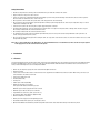
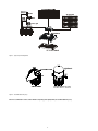
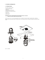
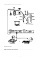
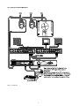
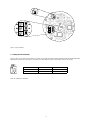
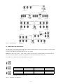
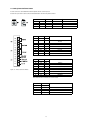
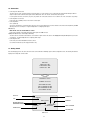
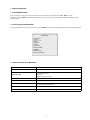
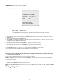
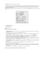
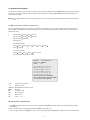
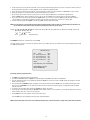
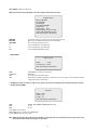
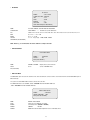
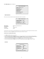
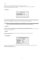
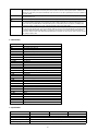
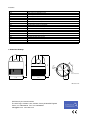
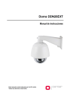
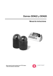
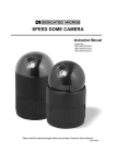
Installation and Operating Manual
Fastrax
Dome Video Camera for Ceiling and Wall Mounting
EDC-141E, EDC-142E, EDC-143E
1
Contents
1.
Introduction .............................................................................................................................................................................................................. 3
1.1
Features ................................................................................................................................................................................................................... 3
2.
Installation and Configuration ................................................................................................................................................................................... 5
2.1
Package Contents..................................................................................................................................................................................................... 5
2.2
Basic Configuration of Fastrax II Dome Camera System ............................................................................................................................................ 6
2.2.1
Single Multiplexer..................................................................................................................................................................................................... 7
2.2.2
Single User with Two Multiplexer .............................................................................................................................................................................. 8
2.2.3
Two Multiplexer with Slave Keyboard Controller ........................................................................................................................................................ 9
2.2.4
Two Multiplexer with Slave Keyboard Controller (method 2) .................................................................................................................................... 10
2.3
Setting Unit For Termination.................................................................................................................................................................................... 11
2.4
Setting Address(Id) of Dome Camera ...................................................................................................................................................................... 12
2.5
Setting Protocol of Dome Camera .......................................................................................................................................................................... 13
2.6
Connection ............................................................................................................................................................................................................ 14
Connecting to the RS-485....................................................................................................................................................................................... 14
Connecting to the Monitor....................................................................................................................................................................................... 14
Connecting Alarms.................................................................................................................................................................................................. 14
Connecting the Power............................................................................................................................................................................................. 14
2.7
Getting Started ....................................................................................................................................................................................................... 14
3.
Program and Operation........................................................................................................................................................................................... 15
3.1
Selecting Dome Camera ......................................................................................................................................................................................... 15
3.2
Accessing On-Screen Menu Utility .......................................................................................................................................................................... 15
3.3
How To Control On-Screen Menu Utility................................................................................................................................................................... 15
3.4
Auto Scan............................................................................................................................................................................................................... 16
3.5
Preset..................................................................................................................................................................................................................... 17
3.6
Shortcut Preset Program......................................................................................................................................................................................... 18
3.7
Tour ....................................................................................................................................................................................................................... 18
3.8
Pattern ................................................................................................................................................................................................................... 19
3.9
Alarm ..................................................................................................................................................................................................................... 20
3.10
Area Title ............................................................................................................................................................................................................... 20
3.11
Privacy Zone........................................................................................................................................................................................................... 21
3.12
Camera ................................................................................................................................................................................................................. 22
Focus Control ......................................................................................................................................................................................................... 22
WB(White Balance) Control ..................................................................................................................................................................................... 22
AE Control............................................................................................................................................................................................................... 23
Line Lock Control.................................................................................................................................................................................................... 23
Night Shot Menu..................................................................................................................................................................................................... 23
3.13
Dome Setup ........................................................................................................................................................................................................... 24
Home Function Setup ............................................................................................................................................................................................. 24
OSD Display Setup.................................................................................................................................................................................................. 24
View Direction ........................................................................................................................................................................................................ 25
Dome OSD Display ................................................................................................................................................................................................. 25
Area Display ........................................................................................................................................................................................................... 25
View Angle Setup.................................................................................................................................................................................................... 25
Panning Ragne ....................................................................................................................................................................................................... 25
Tilt Over Angle ........................................................................................................................................................................................................ 25
Flip......................................................................................................................................................................................................................... 26
Initialize Data.......................................................................................................................................................................................................... 26
Origin Offset ........................................................................................................................................................................................................... 26
Dome Reset............................................................................................................................................................................................................ 26
System Information ................................................................................................................................................................................................ 26
4.
Troubleshooting ...................................................................................................................................................................................................... 27
5.
Glossary ................................................................................................................................................................................................................. 27
6.
Short-Cut Key ......................................................................................................................................................................................................... 28
7.
Specifications......................................................................................................................................................................................................... 28
8.
Dimensional Drawings............................................................................................................................................................................................ 30
2
Safety Instructions
• Read these safety instructions and the operation manual first before you install and commission the camera.
• Keep the manual in a safe place for later reference.
• Protect your camera from contamination with water and humidity to prevent it from permanent damage. Never switch the camera on when it gets wet.
Have it checked at an authorized service center in this case.
• Never operate the camera outside of the specifications as this may prevent the camera functioning.
• Do not operate the cameras beyond their specified temperature, humidity or power ratings. Operate the camera only at a temperature range of -10°C to
+50°C and at a humidity of max. 90%.
• To disconnect the power cord of the unit, pull it out by the plug. Never pull the cord itself.
• Pay attention when laying the connection cable and observe that the cable is not subject to heavy loads, kinks, or damage and no moisture can get in.
Do not attempt to disassemble the camera board from the dome.
• Do not attempt to disassemble the camera board from the dome.
• The warranty becomes void if repairs are undertaken by unauthorized persons. Do not open the camera housing. Maintenance and repair have to be
carried out only by authorized service centers.
• Do not use strong or abrasive detergents when cleaning the dome. Use a dry cloth to clean the dome surface. In case the dirt is hard to remove, use a mild
detergent and wipe gently.
Note: This is a class A digital device. This digital device can cause harmful interference in a residential area; in this case the user may be required
to take appropriate corrective action at his/her own expense.
1. Introduction
1.1 Features
The Fastrax II Keyboard Controller and the Fastrax II dome camera make up the building blocks for any surveillance/security system. Using multiple Keyboard
Controllers and multiple dome cameras, no place is too large for monitoring. Extensible and flexible architecture facilitates remote control functions for a
variety of external switching devices such as multiplexers and DVRs.
• Built-in 18x (23x,25x) times optical power zoom camera with True Night Shot function
• 240 Preset positions
• 8 Tours consist of Preset, Pattern, Auto-Scan and Tour itself can be programmed over 300 functions and Preset location. While moving, each Preset scan
can be watched in smooth Vector Scan mode.
• 8 Auto Scan including vector scan
• 4 Pattern (240seconds)
• 8 Privacy zone
• 8 Alarm input / 4 Aux out (NC & NO)
• Variable speed from 0.1°/sec to 90°/sec
• Turbo speed is Max 360°/sec with Ctrl key pressed
• Maximum speed is inversely proportional to the zoom ratio
• Maximum speed is 380°/sec when preset command.
• Programmable user preferences (alarm, preset, title, etc.)
• Up to 999 selectable camera addresses (Optional 3999)
• Built-in RS-485/422 receiver driver
• Built-in power-line surge protection and lightning protection
• Clear bubble with black liner (shelter) for concealing the camera
• Optional Tinted Bubble, Indoor & Outdoor pendant housing with heater & blower, Indoor Flush Mount, Parapet mount & Roof Top mount
3
Figure 1 - Typical System Configuration
Figure 2 - Assemble bubble ring ass’y
Note: It is recommended to remove camera window for improving picture quality when you assemble bubble ring ass’y.
4
2. Installation and Configuration
2.1 Package Contents
The package contains the following.
1x Fastrax II E (Dome Camera)
1x Bubble Ring
1x Instruction Manual (This Document)
3x Assembly Screws for Attaching Fastrax II E
3x Plastic Anchor
1x 10Pin Connector
2x12Pin Connector
CAUTION: Be sure to have caution labels(E version only) on both body and base of the camera.
Different version will not support alarm input and output.
The dome camera is for use in surface mounting applications and the mounting surface should be capable of supporting loads up to 10lb (4.5kg).
The dome camera’s base should be attached to a structural object, such as a hard wood, wall stud or ceiling rafter that supports the weight of the dome
camera.
Figure 3 - Installation
5
2.2 Basic Configuration of Fastrax II Dome Camera System
Figure 4- Basic installation diagram
The dome camera must be installed by qualified service personnel in accordance with all local and federal electrical and building codes.
The system should be installed according to Figures 4 through 9.
6
2.2.1 Single Multiplexer
Figure 5 - Single Multiplexer
7
2.2.2 Single User with Two Multiplexer
Figure 6 - Two Multiplexer
8
2.2.3 Two Multiplexer with Slave Keyboard Controller
Figure 7 - Two Multiplexer with Slave Keyboard Controller
9
2.2.4 Two Multiplexer with Slave Keyboard Controller (method 2)
Figure 8 - Two Multiplexer with Slave Keyboard Controller (method 2)
10
Figure 9 - Layout of Switches
2.3 Setting Unit for Termination
The device which is connected at end of line, whether it is a dome camera or keyboard controller, must be terminated by setting the appropriate DIP switch.
Without proper termination, there is potential for control signal errors. Total length of the cable for communication should not exceed 1.2km.
SW1
1
2
Terminated
ON
ON
Not terminated
OFF
OFF
Figure 10 - Setting Unit for Termination
11
Figure 11 - Termination Diagram
2.4 Setting Address (ID) of Dome Camera
To prevent damage, each dome camera must have a unique address (ID). When installing multiple dome cameras using a multiplexer, it is suggested that the
dome camera address matches the multiplexer port number.
If you wan to set the address more than 999, you should connect the service provider.
Example: Port 1 = Dome 1, Port 2 = Dome 2 ... Port 16 = Dome 16. If more than 16 dome cameras are installed using two or more multiplexers, ID of the
dome camera should be ID of MUX x No. of camera IN. (e.g. multiplexer ID= n, Camera IN= m then ID of Dome =16x(n-1)+m )
Refer to Figures 4-5 for setting the dome camera address (ID) and protocol selection.
Dome ID
SW1
SW2
SW3
1
1
0
0
2
2
0
0
…
…
…
…
999
9
9
9
Beyond ID 999, contact your service provider.
Figure 12 - Setting Address (ID) of Dome Camera
12
2.5 Setting Protocol of Dome Camera
If a dome camera is to be installed with a Fastrax keyboard controller, select F2 protocol.
Consult service personnel if a dome camera is installed with device other than a keyboard controller.
S/W
D1
D2
D3
D4
Figure 13 – Protocol Selection Switches
S4-1
S4-2
S4-3
S4-4
On
Off
Function
Enable
PAL
Disable
NTSC
RS-422
RS-485
Alarm
NTSC/PAL
Reserved
RS-422/RS-485
D5
D6
D7
S5-1
S5-2
S5-3
Off
Off
Off
Off
Off
Off
On
On
On
On
Off
On
On
Off
Off
On
On
On
Off
On
Off
On
Off
On
F2,F2E,P,D,E & Ph Protocol
(Default)
Reserved
S 422
Reserved
V Protocol
Reserved
D Color
Reserved
D8
D9
D10
Baud Rate
S5-4
S6-1
S6-2
Off
Off
Off
Off
On
On
On
Off
Off
On
On
Off
Off
On
Off
On
Off
On
Off
On
Off
2400 bps
4800 bps
9600 bps (Default)
19200 bps
38400 bps
57600 bps
115200 bps
On
On
On
230400 bps
Protocol
Unless Baud rate match, universal protocol will not work.
D11
D12
S6-3
S6-4
Off
Off
On
On
Off
On
Off
On
13
Camera
Default cameras (Default)
Reserved
Reserved
Reserved
2.6 Connections
• Connecting to the RS-485/-422
The dome camera can be controlled remotely by an external device or control system, such as a control keyboard, using RS-485 half-duplex, RS-422
duplex or simplex serial communications signals. Connect Marked Rx+, Rx- to Tx+ and Tx- of the RS-485 control system.
If control system is RS-422, connect Rx+ (Tx+), Rx+ (Tx-) and Rx+, Rx- of the dome camera to Tx+, Tx- and Rx+, Rx- of the control device respectively.
• Connecting Video out connector
Connect the video out (BNC) connector to the monitor or video input.
• Connecting Alarms
AL1 to 8 (Alarm In)
You can use external devices to signal the dome camera to react on events. Mechanical or electrical switches can be wired to the AL (Alarm In) and GND
(Ground) connectors. See Chapter 3 - Program and Operation for configuring alarm input.
GND (Ground)
NOTE: All the connectors marked GND are common.
Connect the ground side of the Alarm input and/or alarm output to the GND connector.
NC(NO)1 TO 4 (Normal Close or Normal Open: Alarm Out)
The dome camera can activate external devices such as buzzers or lights. Connect the device to the NC(NO) (Alarm Out) and COM (Common) connectors.
See Chapter 3 - Program and Operation for configuring alarm output.
• Connecting the Power
Connect the power of AC 24V 850mA to the dome camera.
Use certified / Listed Class 2 power supply transformer only.
2.7 Getting Started
Once installed apply power to the dome camera. The dome camera will start a initializing sequence. When configuration is done, the following information is
displayed on the keyboard controller’s LCD.
RAM TEST
CHECK NO. : OK!
CHECK AAAA : OK!
CHECK 5555 : OK!
FASTRAX II E Vx.xxx
CAMERA TYPE xxxx
WAIT DOME SETTING.
INIT TILT ORGIN SET OK
INIT PAN ORGIN SET OK
INIT CAMERA SET OK
PRESET No.
CAMERA TITLE
001 PRESET
TITLE
EMPTY DATA !
CAMERA ID
INFORMATION DISPLAY
COMMAND ON WORKING
T001
DOMEID:0001
ALARM:1
W_360.0,090.0
PAN & TILT DEGREE
ALARM DISPLAY
VIEW DIRECTION
OSD Position
14
3. Program and Operation
3.1 Selecting Dome Camera
Before you program or operate a dome camera, you must select the dome camera by pressing the dome camera No. + CAM successively.
Example: Pressing 1, 0 and CAM key sequentially will select dome camera 10. The selected dome camera ID will be displayed on the LCD monitor of the
keyboard controller.
3.2 Accessing On-Screen Menu Utility
You can call up the On-screen menu utility on your monitor by pressing MENU key on the keyboard controller, the following On-screen menu utility will appear:
MAIN MENU
AUTO SCAN
PRESET
TOUR
PATTERN
ALARM
AREA TITLE
PRIVACY ZONE
CAMERA
DOME SETUP
EXIT(ESC TO EXIT)
3.3 How to control On-Screen Menu Utility
Action
Function
MENU
Call on On-screen menu utility
Joystick left or right
Go into the sub-menu items.
Execute the command(exit)
Change value.
Navigate through the menu items.
Joystick up or down
Navigate through the menu items.
Joystick down
Finish editing title. Same effect as Enter key
Zoom handle twist
Change value.
Enter editing title mode at Preset menu.
CTRL + Joystick
PTZ control of the selected camera
ESC
Escape (EXIT)
15
3.4 Auto Scan
(First Item of the Main menu / Shortcut: Scan)
The Auto scan supports up to 8 programmed angles at user-programmable speeds. Follow these steps to program Auto Scan:
AUTO SCAN SETUP
SCAN 01
: AUTOSCAN01
SPEED(MODE) : FAST VECTOR
START ANGLE : 127.1, 027.7 X7
END ANGLE
: 157.7, 080.7 X13
SCAN DIR.
: CCW
SWAP
: OFF
SAVE AND EXIT (ESC TO CANCEL)
HOLD DOWN CTRL KEY
WHILE SELECT POSITION.
SPEED(MODE):
NORMAL1~NOMAL9,SLOW VECTOR,FAST VECTOR
NORMAL1 (SLOWER) <––> NORMAL9 ( FASTER)
SLOW VECTOR, FAST VECTOR: Move from start point to end point including tilt and zoom simultaneously and linearly.
In case of HID2404HCExxx model, zoom is fixed at more wide angle and the zoom magnification information is not displayed.
1. Press the Scan key to enter Auto Scan menu directly. Or press the Menu key to display the main menu on the monitor. Scroll to Auto Scan and push the
Joystick to the right.
2. Select an Auto Scan number by pushing the Joystick left or right.
3. Twist the Joystick to enter the title by scrolling through the alphanumeric characters and pushing the handle to the right or left to move to the next space.
Press Enter key or push the Joystick down to finish title mode
4. When finish entering the title, select „START ANGLE” with the Joystick. Hold down the Ctrl/PGM key while selecting the start position using the Joystick.
Current panning position will be displayed. Release Ctrl/PGM key to complete the selection of the start position.
5. Push the Joystick downward to select „END ANGLE.” Hold down the Ctrl/PGM key while moving the Joystick to select the end position. The end position
angle should be larger than start position. Release the Ctrl/PGM key to complete the selection of the end position.
6. Push the Joystick downward to select „Tilt & Zoom.” Set the zoom and tilt angle by holding down the Ctrl/PGM key.
7. Push the Joystick downward to select „Speed” and set the speed by twisting the Joystick clockwise or counterclockwise.
8. Select Save and Exit by pushing the Joystick to the right. Press ESC to exit the program without saving.
Pressing the Home key will delete stored angle data. Start/End angle will be turn to 000 immediately.
NOTE: Using the Tour mode in conjunction with preset and Auto Scan, you can make the camera travel from one preset position to another preset
position at a specific speed. (Pan only)
a. Before entering the Auto Scan menu, select a preset position as a starting point for Auto Scan.
Example: 2 + Prst and do step 1 to 4. Instead of step 5, just press the Ctrl/PGM key at the start angle position, the current position will be displayed as a
start position.
b. Save and exit from the menu.
c. In normal mode, call a preset to be the end point of scan. Press 3 + Prst then press Scan key to enter the Auto Scan menu. Move the cursor position to
END ANGLE. Just press Ctrl/PGM key at the end angle position. Do step 7 to 9.
Example: Preset 001>002>003>004>005>006, Auto Scan 01 starts at 002, ends at 003, Auto Scan 02 starts at 005, ends at 006. Tour 001, 002, A01, 004,
A02.
1
2 2~3
Where
4
5~6
1
2 2~3 ......
: Quick move, ~ : Programmed speed by Auto Scan.
16
3.5 Preset
(Second Item of the Main menu / Shortcut: Prst)
If you need to view specific locations routinely, you should program presets. A preset is a programmed video scene with automatic pan, tilt, zoom, focus and
iris settings. Once programmed, entering the number and pressing a preset button on your controller automatically calls up the preset. In addition, presets
may be assigned to alarm actions or as the „home” position for the dome camera. As many as 240 presets, whose positions are saved in the dome’s nonvolatile memory, may be programmed.
There are three pages of preset menu, each page can hold 80 presets. Pages can be scrolled by pushing the Joystick to the left or right on the first or last No.
of Preset.
PRESET SETUP
NO. 001
FOCUS
IRIS
DWELL
: xxxxxxxxxxxxxxxx
: AUTO/ MANUAL
: AUTO/ MANUAL
: 03~99 (Sec)
1234567890
1234567890
00 * * * =====
01==========
02==========
03==========
04==========
05==========
06==========
07==========
JOY-LEFT TO PREV. PAGE
SAVE AND EXIT(ESC TO CANCEL)
x : 16 digits of title for preset label
= : blank preset position
* : position has the preset
: Current cursor position
Follow steps below to store the Preset positions:
1. Press Menu to display the main menu. Select the Preset option by using the Joystick to the right. (Press Prst to go directly to the Preset menu without
going through the main menu.)
2. Select the blank preset position to be stored by pushing the Joystick up, down, right, or left.
3. The position, which is marked with , already has the preset view assigned. To review the stored preset, press Prst key on the The camera will show
the stored preset view.
4. After selecting a blank position, press and hold Ctrl/PGM, use the Joystick to control the direction of the camera and lens.(Ctrl+Joystick)
5. After aiming the camera (view direction and lens control), release Ctrl/PGM. Then twist the Joystick handle or Press Tele or Wide Key to store the
selected view. The position number will be displayed and the user will be prompted to enter a preset title.
6. Enter the title for the preset position using the Joystick. (Rotate handle clockwise and counterclockwise or press Tele or Wide Key to scroll through the
alphanumeric characters, push the handle to right or left to select next or previous digit.)
7. When you are finished entering the title, push the Joystick downward. Set the focus by pushing the Joystick to the right or left. Set the IRIS value in the
same manner as the focus.
8. Move to the DWELL setting by pushing the Joystick down. Twist the Joystick clockwise or counterclockwise to increase or decrease dwell time of the
preset position.
9. To select the next page of presets, scroll the page by pushing the Joystick to the left on the first and last columns of the menu.
10. Repeat steps 2 through 7 for each additional preset position.
11. To edit the title of a stored preset, use the Joystick to position the cursor on the desired preset position. Press the Prst key to recall the stored preset.
Twist the zoom handle clockwise to enter the preset title, focus and IRIS. Preset titles are useful with short cut preset programming. Refer to Shortcut
programming below.
12. Select Save and Exit by pushing the Joystick to the right. Press ESC to exit the Preset menu without saving.
NOTE: Press the Home key at programmed position to delete a programmed preset view.
17
3.6 Shortcut of Preset Program
Select a view to be stored (direction of the camera, zoom and focus), then press No. (1 to 240), and then press Pgm, Prst subsequently. The current view will
be stored to the selected preset number if position is empty. If selected preset number is not empty, „PRESET EXISTING” message will be displayed on the
monitor and ask to overwrite.
Example: 1, 0, 1 + Pgm + Prst will store current view as preset No. 101. In this case, focus and Iris mode will be programmed as Auto, dwell time will be set
to 3 sec.
3.7 Tour
(THIRD ITEM OF THE MAIN MENU / SHORTCUT: Tour)
There are 8 programmable Tours. Each Tour consists of up to 42 Preset positions, Patterns, Scans or other Tours (second-level). Using second-level Tours, it
can be expanded to over 300 functions in a single Tour. However Tours in second level Tour will be ignored when called by a Tours. The following example
illustrates this concept:
If
Tour1 has Preset1
Preset2
Tour2
Tour3 and
Tour2 has Preset3
Preset4
Tour4
Preset5 and
Tour3 has Preset6
Pattern and
Tour4 has Preset7.
Tour1 executes as follows:
Preset1
Preset2
Preset1
... (Repeat)
Preset3
Preset4
Preset5
Preset6
Preset5
Preset1 ... Repeat
Pattern1
Tour2 executes as follows:
Preset3
Preset4
Preset7
(Tour4 is still valid if called directly from Tour2.)
TOUR 01
: xxxxxxxxxxxxxxxx
SCAN TYPE : NORMAL
DWELL
: 03
=== === 003 === === === ===
A08 === === === === === ===
=== T02 === 001 === === ===
=== === === T08 === === ===
=== === === === === === ===
=== === === === === === ===
SAVE AND EXIT ( ESC TO CANCEL)
PRESS FUNCTION KEY AND THEN ZOOM
KEY TO SELECT FUNCTION NO
xxxxx :
16 digits of title for tour label
=== :
blank preset position
SCAN TYPE : Max (Normal)/ Slow V. Scan/ Fast V. Scan
DWELL :
03-99 Sec
003 :
Preset 003 (1~240)
A08 :
Auto Scan 08 (1~8)
P01 :
Pattern 01 (1~4)
T02 :
Tour 02
(1~8)
Follow the steps below to program the Tours:
1. Press Menu to display the main menu on the monitor. Scroll to Tour and push the Joystick to the right to enter the Tour menu. Or just press the Tour key
on the keyboard
2. Choose an empty location to be programmed by pushing the Joystick up, down, right, or left.
3. To see a stored preset view, use the Joystick to move the cursor to a stored position. By pressing Prst key, the camera will move to the stored Preset view.
18
4. To add a stored preset as a Tour, twist the Zoom handle or press Zoom Key (Programmed preset will scroll). To remove a stored preset from the Tour, press
the Home key, blank position mark (===) will be displayed. You can overwrite the programmed position.
5. To place functions other than preset, press Tour, Ptrn, or Scan for Tour, Pattern or Auto Scan respectively and the use zoom handle or key to select No.
6. Repeat Step 2 through 5 for each desired position. Each title will be displayed on top of the line.
7. Up to 36 Presets, Tours, Patterns Scans can be selected for a Tour. You can expand the Tour sequence by calling other programmed tours.
Push the Joystick handle to right or left while the cursor is on the top of the line (TOUR 01) to select another page of the Tour menu. (TOUR 01)
8. You can enter a title for the selected Tour by twisting the Joystick while the cursor is on the top of the line (TOUR 01). Rotate the handle clockwise or
counterclockwise to scroll through the alphanumeric characters. Push the handle to the right or left to select the next or previous digit.
9. Select Save and Exit by pushing the Joystick to the right. Press ESC to exit the program without saving.
NOTE: Press the Home key at a programmed position to delete programmed function. In the Tour mode, in conjunction with preset and Auto Scan,
you can make the camera travel from a preset position to another preset position at a specific speed.
Example: Preset 001>002>003>004>005>006, Auto Scan 01 starts at preset 002, ends at preset 003, Auto Scan 02 starts at preset 005, ends at preset
006; Tour 001, 002, A01, 004, A02.
1
2 2~3
where
3.8 Pattern
4
5~6, repeat
: Quick move, ~ : Programmed speed
(Fourth 4 Item of the Main menu / Shortcut: Ptrn)
The Pattern feature records user control of the selected dome camera for up to 240 seconds. Up to four 4 patterns can be stored and played back by pressing
No.+ Ptrn keys subsequently.
PATTERN SETUP
NO.
TITLE
01: xxxxxxxxxxxxxxxx
02: xxxxxxxxxxxxxxxx
03: xxxxxxxxxxxxxxxx
04: xxxxxxxxxxxxxxxx
TOTAL
SEC
000
041
010
020
071
SAVE AND EXIT ( ESC TO CANCEL)
HOLD DOWN CTRL KEY
WHILE RECORDING.
Follow steps below to program the Pattern:
1. Press Menu key to display the main menu on the monitor.
2. Scroll down to PATTERN and push the Joystick to the right. Or simply press the Ptrn key rather than use the Main Menu.
3. Select the empty Pattern number to be programmed by pushing the Joystick up or down. If last column is not 000, a pattern has already been recorded.
Patterns can be over written.
4. Press and hold down the Ctrl/PGM key while controlling the camera direction and zoom with the Joystick. Your controls will be automatically recorded
until you release the Ctrl/PGM key. You can repeat this procedure until you have the pattern you want. Previously recorded patterns will be overwritten
each time you do this.
5. Scroll down to the Save and Exit option and push the Joystick to the right to save and exit.
6. You can title the selected Pattern by twisting the Joystick. Rotate the handle clockwise or counterclockwise to scroll through the alphanumeric characters,
push the handle to right or left to select next or previous space.
7. Pressing ESC will not save your information and exits to the previous mode.
7. Press the Home key at any programmed position to delete the programmed pattern.
NOTE: If total recording time reaches 240 seconds, it will automatically stop for a moment and restart recording. Previous data will be overwritten.
19
3.9 Alarm
(This menu shows on only specific model, Fifth Item of Main menu)
ALARM SETUP
NO PRIO PRS IN OUT HOLD LATCH
01
1 001 OFF OFF
03 OFF
02
8 001 OFF OUT1 03
OFF
03
1 240 NO OUT1 03
OFF
04
2 001 NC OUT4 03
OFF
05
1 001 OFF OFF
03
OFF
06
8 001 OFF OUT1 03
OFF
07
1 240 NO OUT1 03
OFF
08
2 001 NC OUT4 03
OFF
SAVE AND EXIT ( ESC TO CANCEL)
NO :
Alarm input number
PRIO :
Lower No. has higher priority, Equal priority alarms will be serviced repeatedly.
PRS :
Stored preset number to be called by alarm.
IN :
NO/NC - normally open /Closed OFF - ignore
OUT :
OUT1~OUT4 - Relay out 1,2,3,4, OFF - No output.
HOLD :
Alarm will be held for programmed time (01 to 99 seconds)
LATCH : ON - Shows all alarms including past alarm, OFF - Shows activated alarms only.
There is one „0” PRIO which is the highest priority. „0” priority can choose Autoscan, Pattern or Tour. When responding „0” priority alarm, there is no respond
other alarm until finishing „0” priority action
1. Press Menu to display the main menu on the monitor. Select the Alarm option by pushing the Joystick up or down and push to right to enter the detail
menu.
2. Select the alarm input number by pushing the Joystick up or down and select the column you wish to setup. Selected position will be highlighted.
3. Select the Preset, Status of Input (NC/NO/OFF), and Output (OUT1~4/OFF) by pushing the Joystick to the right or to the left.
4. To increase or decrease the preset number or to change the status or output number, twist the Joystick clockwise or counterclockwise. In case of preset,
programmed preset number will be scrolled.
5. Select the Save and Exit option by pushing the Joystick up or down. Save and exit the program by pushing the Joystick to the right. Press ESC to exit the
program without saving.
3.10 Area Title
(Sixth Item of Main menu)
Enter a specific name on programmed angle between START and END. For the screen below, when the camera points at an angle between 124.3° to 359.5°,
ABC will be displayed on the screen.
ALARM TITEL SETUP
NO
TITLE
START
01
ACB
124.3
02
xxxxxxxxxxxxxxxx =====
03
xxxxxxxxxxxxxxxx =====
04
xxxxxxxxxxxxxxxx =====
05
xxxxxxxxxxxxxxxx =====
06
xxxxxxxxxxxxxxxx =====
07
xxxxxxxxxxxxxxxx =====
08
xxxxxxxxxxxxxxxx =====
SAVE AND EXIT (ESC TO CANCEL)
HOLD DOWN CTRL KEY
WHILE SELECTIONG SECTION
20
END
359.5
=====
=====
=====
=====
=====
=====
=====
Pages can be scrolled through by pushing the Joystick to the left or right on the first or last column of the menu. Pushing the Joystick to left on the „NO”
column (01 ~ 08) of the menu to scroll to the previous page. Push the Joystick to right on the „END” column to go to the next page.
1. Press Menu to display the main menu on the monitor. Select the Area Title option by pushing the Joystick up or down and push to right to enter the detail
menu.
2. Select the area number by pushing the Joystick up or down. Select Start, End or number column to be set by pushing the handle to the right or left.
The selected column will be highlighted.
3. To enter area title, select the number column and rotate the handle clockwise or counterclockwise. You can select alphanumeric characters by rotating the
handle. Move to the next character by pushing the Joystick to the right. To finish entering the title, push the Joystick down.
4. To adjust panning limit, press the Ctrl/PGM key and hold down. Then use the Joystick to aim the desired direction. The end limit must be in an increasing
direction. (Start < End).
5. When you press the Ctrl/PGM key, the current position of the pan will be displayed in the highlighted column. With this feature, you can easily set the next
start point as the previous end point.
6. Select the Save and Exit option by pushing the Joystick up or down. Save and exit the program by pushing the Joystick to the right. Press ESC to exit the
program without saving.
6. Pressing the Home key will delete programmed data. (Angles will be turned ==== immediately.)
3.11 Privacy Zone
(Seventh Item of Main menu)
Hide up to 8 unwanted views in a camera.
PRIVACY ZONE SETUP
NO
TITLE
METHOD
01
xxxxxxxxxxxxxxxx
ON
BLOCK
02
xxxxxxxxxxxxxxxx
OFF
V.OFF
03
xxxxxxxxxxxxxxxx
NONE ====
04
xxxxxxxxxxxxxxxx
NONE ====
05
xxxxxxxxxxxxxxxx
NONE ====
06
xxxxxxxxxxxxxxxx
NONE ====
07
xxxxxxxxxxxxxxxx
NONE ====
08
xxxxxxxxxxxxxxxx
NONE ====
SAVE AND EXIT ( ESC TO CANCEL)
HOLD DOWN CTRL KEY
WHILE SELECTION ZONE TO BE MASKED.
1. Press Menu to display the main menu on the monitor. Select the Privacy Zone option by pushing Joystick up or down and push to right to enter the detail
menu.
2. Select the privacy zone number by pushing the Joystick up or down.
3. To enter the zone name, rotate the handle clockwise or counterclockwise. You can select alphanumeric characters by rotating the handle. Move to the next
character position by pushing the Joystick to the right. To finish entering the title, push the Joystick down or press the Enter key.
4. To adjust the „marked” (privacy) area, press and hold down the Ctrl/PGM key and then use the Joystick (direction and zoom) until you get desired view.
Release the key, the right column will be set to ON.
5. You can overwrite an existing zone. Use the Home key to delete the marked zone, or push the Joystick to the right or left to turn the stored zone On or Off.
6. Select the Save and Exit option by pushing the Joystick up or down. Save and exit the program by pushing the Joystick to the right. Press ESC to exit the
program without saving.
6. Press the Home key to delete programmed privacy zone.
21
3.12 Camera
(Eighth Item of Main menu)
NOTE: The menu features will vary depending on the camera module installed in your dome camera.
CAMERA SETUP
FOCUS CONTROL
WB CONTROL
AE CONTROL
LINE LOCK CONTROL
SHARPNESS : 9
BACK LIGHT
: OFF
DIGITAL ZOOM : OFF/2x/4x/ MAX
NIGHT SHOT CONTROL (optional)
SAVE AND EXIT(ESC TO CANCEL)
SHARPNESS
The higher the value, the more edges in the picture will be enhanced (0~15).
BACK LIGHT
Objects in front of bright backgrounds will be clearer with BLC ON.
Digital ZOOM
OFF : Zoom range is limited to the optical.
2x :
Zoom is extendable up to 2x of digital range.
4x :
Zoom is extendable up to 4x of digital range.
MAX:
Zoom is extendable Max digital Zoom range.
• FOCUS CONTROL
FOCUS SETUP
MODE
: AUTO
AF SENSITIVITY : HIGH
SAVE AND EXIT(ESC TO CANCEL)
MODE :
AUTO / MANUAL Use manual mode in normal use.
AF SENSITVITY:
HIGH / LOW
HIGH:
Use this option when shooting fast motion.
LOW:
Offers better focus stability. In low luminance conditions, Auto Focus stops operation even when brightness changes,
enabling stable images of moving objects.
• CAUTION: Avoid continuous, 24-hour use of the auto focus. This may cause the lens to malfunction, and it will shorten the lifespan of the lens.
• WB (white balance) CONTROL
WB SETUP
MODE : AUTO
R GAIN : 210
B GAIN : 155
SAVE AND EXIT(ESC TO CANCEL)
MODE
MANUAL / AUTO / INDOOR / OUTDOOR / ONE PUSH / ATW
RGAIN
0 ~ 255
BGAIN
0 ~ 255
Use the ATW mode for normal use.
RGAIN / BGAIN modes are controllable only in MANUAL Mode
Push the Joystick to the right or left to change.
NOTE : „ONE PUSH” means that when rotating the Joystick handle for a moment the lens moves to adjust the focus for the subject. The focus lens
then holds that position until the next rotating the Joystick handle.
22
• AE CONTROL
AE SETUP
MODE
: FULL AUTO
SLOW SHUTTER : MANUAL
IRIS
: F2.4
GAIN
: 0 DB
BRIGHT
: 14
SHUTTER
: 1/60
SAVE AND EXIT(ESC TO CANCEL)
MODE
FULL AUTO / MANUAL / SHUTTER PRIO / IRIS PRIO / BRIGHT
SLOW SHUTTER
AUTO / MANUAL -----
IRIS
CLOSE / F22 / F19 / F16 / F14 / F11 / F9.6 / F8.0 / F6.8 / F5.6 / F4.8 / F4.0 / F3.4 / F2.8 / F2.4 / F2.0 / F1.6 / F1.4
GAIN
0 / 2 / 4 / 6 ...... / 28 / -3 DB
BRIGHT
0, 2, 3, 4 ..... 29, 30
SHUTTER
1/1 , 1/2 , 1/4(3), 1/8(6). .. 1/4000, 1/6000, 1/10000
AUTO effects only FULL AUTO mode
SAVE AND EXIT (ESC TO CANCEL)
NOTE : Values in ( ) are for PAL Camera. The value is different according to the model.
• LINE LOCK CONTROL
LINE LOCK MENU
MODE :
INTERNAL
PHASE :
125
EXIT (ESC TO EXIT)
MODE
INTERNAL / EXTERNAL
Adjusts phase of picture with other
PHASE
0~255
cameras in EXTERNAL mode.
EXIT (ESC TO EXIT)
• NIGHT SHOT MENU
The NIGHT SHOT option removes the IR cutoff filter of the camera and makes the camera sensitive to near infrared. This will set the BLACK & WHITE option to
ON automatically.
The operator can enable NIGHT SHOT for all dome cameras at the same time.
If the NIGHT SHOT mode is set to GLOBAL, „9 9 9„ + Enter/Glbl will turn Off the NIGHT SHOT mode
„8 8 8” + Enter/Glbl will turn On the NIGHT SHOT mode.
NIGHT SHOT SETUP
MODE
: MANUAL
LOCAL CONTROL : OFF
EXIT (ESC TO CANCEL)
MODE
MANUAL / AUTO / GLOBAL
AUTO:
Camera goes in to B&W mode at low light.
GLOBAL:
Controlled by remote (888/999 + EnterGlbl).
MANUAL
CONTROL
MANUAL:
ON/OFF will enable and disable Night Shot mode of an individual camera.
ON / OFF
23
3.13 Dome Setup
(Ninth Item of Main menu)
CONFIGURATION MENU
HOME FUNCTION SETUP
OSD DISPLAY
VIEW ANGLE SETUP
INITIALIZE DATA
ORIGIN OFFSET
DOME RESET
SYSTEM INFORMATION
EXIT(ESC TO EXIT)
• HOME FUNCTION SETUP
After a dome control menu item has been selected, follow the directions below to set the function.
HOME FUNCTION SETUP
HOME FUNCTION
: NONE
FUNCTION NUMBER : --WATING TIME
: 120SEC
FUNCTION ENABLE : OFF
SAVE AND EXIT(ESC TO CANCEL)
HOME FUNCTION
: None/ Preset/ Tour/ Pattern/ Auto Scan
FUNCTION NUMBER
: xxx
WAITING TIME
: 10~240 Seconds
FUNCTION ENABLE
: ON/ OFF
The Home function can be set so that the camera automatically goes to Preset, Tour, Pattern, Auto Scan after the keyboard controller has been idle for a
amount of time. For example, if the Joystick controller is idle for 10 seconds, the camera goes to preset 1.
Follow these steps to program the Home position:
1. Press Menu to display the main menu on the monitor.
2. Select Home Function by pushing the Joystick to the right or to the left to scroll through the None, Tour, Pattern, Auto Scan and Preset functions.
3. Select Function Number by pushing the Joystick down, and push the Joystick to the right or to the left. The executable function number will scroll.
Each function has maximum numbers. For example, you can have 240 Presets, 8 Tours, 4 Patterns and 8 Auto Scan options.
4. Select Function Time by pushing the Joystick down. Push the Joystick to the right or to the left to select from 10 to 240 seconds.
5. Select Function Enable by pushing the Joystick down. Turn the Home Enable ON or OFF by pushing the Joystick to the right or to the left.
• OSD DISPLAY
DISPLAY SETUP
CAMERA TITLE
: XXXXXXX
VIEW DIRECTION
: OFF
DOME OSD DISPLAY : ON
AREA DISPLAY
: OFF
TILT OVER ANGLE
: W/O BUBBLE
FILP
: ON
SAVE AND EXIT(ESC TO CANCEL)
24
CAMERA TITLE
: 8 CHARACTER CAN BE SET
VIEW DIRECTION
: ON / OFF
DOME OSD DISPLAY
: ON / OFF
AREA DISPLAY
: ON / OFF
TILT OVER ANGLE
: ON / WITH BUBBLE / W/O BUBBLE
FILP
: ON / OFF
• VIEW DIRECTION
„ON” sets current direction as N(north) and the coordinate angle to 000. „OFF” hides the directional title. Every 90 degrees of clockwise rotation will change
the title to E(East), S(South), W(West). If using the ON/OFF option frequently, it is recommended that you set „North” as a Preset. Recall the „North” Preset
before enabling the directional title.
• DOME OSD DISPLAY
All display or title will disappear when DOME OSD DISPLAY sets OFF
• AREA DISPLAY
If this option is enabled, the nearest area title will be displayed when the camera is moving whether by manual operation, Auto Scan, or Pattern. Select ON or
OFF by pushing the Joystick to the right or to the left. The Dome camera’s OSD option will override this function (Dome camera’s OSD must be enabled).
• VIEW ANGLE SETUP
OSD VIEW ANGLE SETUP
PANNING RANGE
FLIP
: ON
TILT OVER ANGLE
: W/O BUBBLE
STABILIZER
: ON (OFF)
SAVE AND EXIT (ESC TO CANCEL)
• STABILIZER
When the Image Stabilizer Function is ON, it helps in obtaining a stable image free of vibration caused by jarring movements. For a vibration frequency of
around 10Hz, correction is approximately 90% (HID2404SHE11X model only).
• PANNING RANGE
When the dome camera is installed near wall, panning range could be programmed by user.
PANNING RANGE MENU
RIGHT LIMIT
: 000.0
LEFT LIMIT
: 000.0
ENABLE
: OFF
SWAP
RIGHT/LEFT
SAVE AND EXIT(ESC TO CANCEL)
• TILT Over Angle
This option is used to set the limit of the horizontal view angle so that the trim ring or ceiling does not obstruct the horizontal image when zooming out (wide angle).
ON: In some installations it is desirable for the dome camera to be able to see the above horizon. When this option is chosen, the dome will tilt up
over the horizon(About 10 degree ). When the lens is zoomed out, you can see the ceiling line. But when the lens is zoomed in the viewing angle is
narrower, and the ceiling line disappears.
Without Bubble: The tilt range of the camera is limited to see the horizon so the picture shows part of the ceiling line.
With Bubble: The tilt range of the camera is limited to see below the horizon (- 10 degrees). Over Angle is not sufficient enough to avoid ceiling
obstructions, please adjust Origin Offset of tilt angle as described below.
25
• FLIP
Allows the dome camera to automatically turn 180 degrees when the camera tilts to its lower position.
When camera reaches floor alone moving object, it will stop. Release the Joystick handle instantly and then pull down to run flip fucntion.
The speed of following object will be same speed as previous.
• INITIALIZE DATA
INITIALIZE DATA
FACTORY DEFAULT
ERASE PROGRAMMED DATA
EXIT(ESC TO EXIT)
Erase all stored data from the Flash-ROM of the selected dome camera. You will be asked to enter Yes or No. If you intend to erase all data then press the
Menu key, otherwise press the ESC key to exit without erasing. The erased data includes all stored data (titles, presets, and tours....) except origin offset.
The offset value is still valid after all data is erased. The offset value can be zero only with default set of Offset origin menu.
CAUTION: All the data in the selected dome camera will be lost unless you download the data into a safe place. (Refer to Download/ Upload data
function in Keyboard Configuration utility.) Data from the selected dome camera can be stored in the keyboard controller temporarily.
If you want to save the data of all installed dome cameras, you need a special I/O interface and software for PC.
• ORIGIN OFFSET
This feature is useful to align a replaced dome camera to the exactly same position as the previously installed dome camera.
Dome camera’s origin set and all data initialize option do not override offset values. Only the default set option in this menu will set the offset value to zero.
This can be used to avoid ceiling obstructions.
• DOME RESET
This feature is used to re-calibrate the orientation of a selected dome camera. Origin offset value is not affected by this function.
(Offset is still valid after origin set)
• SYSTEM INFORMATION
SYSTEM INFORMATION
CAMERA TYPE : XXXXXXX
H/W VERSION
: V1.0
ROM VERSION : V1.0
PROTOCOL
: F2E
BUADRATE
: 9600BPS
EXIT(ESC TO EXIT)
A Dome camera’s Setup menu provides essential information about the dome camera when service is required. When you view this screen, you can
determine the camera type, ROM version.
The information on this screen cannot be modified.
26
4. Troubleshooting
If problems occur, verify the installation of the camera with the instructions in this manual and with other operating equipment. Isolate the problem to the
specific piece of equipment in the system and refer to the equipment manual for further information.
Problem
No video
Poor video quality
Dome cameras lose their positions.
Camera number does not match the
multiplexer number.
Picture is torn when switching
Possible Solution
Verify that power is connected to all pieces of equipment in the system.
Verify that the power switches are in the ON position.
Check the video connections
(see Figures 4).
Check that the BNC connectors are inserted properly.
Check the voltage level of the dome camera.
Check that 8 pin cable is connected to the Keyboard. Check 8 pin cable for Keyboard is proprietary.
(Cable for video is shielded.)
Check termination of Video.
Reset the cameras using the Dome configuration menus.
Check that the dome cameras are inserted properly in the base.
Check the voltage level of the dome camera.
Check the camera ID and insert the BNC cable into the proper input of the multiplexer.
Check Line Lock setting and adjust phase of L/L (see page 23).
5. Glossary
Alarm Actions
Areas
Automatic Gain
Control (AGC)
On-screen Menu
Flip
Home Position
Input Alarm
Input Devices
IR Mode
Line Lock
Name Information
Normal Input State
North Position
Low Shutter
Pattern
Preset
The assigned responses for the dome camera when inputs change from normal to abnormal states.
The dome may run a Preset, Pattern, or have no assigned action for each of the four dome inputs. The dome may also send alarm
states to the host controller for processing. See also Input and Normal Input State.
Programmed start and end points of the dome‘s field of view around its pan axis.
Each area is a part of a circular viewing area that extends around the dome. The areas can be different sizes. Up to 16 areas can
be programmed for the dome.
Allows for the amplification of the video signal in scenes with minimal ambient light. Many low-light scenes result in picture noise.
As gain is increased, the picture noise is also amplified. When AGC is enabled, the value of the gain setting is based on feedback
from the camera. When AGC is disabled, the camera uses the value set for the manual gain setting. The trade-off between picture
level and noise may be adjusted when AGC is disabled.
The text overlay menu system used for setting dome features. The utility is accessed using a
keystroke combination. The utility provides settings for camera functions, zoom, alarms, text
display, and password protection
Allows the dome to automatically turn 180 degrees when the camera tilts to its lower limit and stays in that position for a brief
delay. When the dome flips (rotates), the camera starts moving upward as long as the tilt control is kept in the down position.
Once the Joystick handle is released to neutral position, the tilt control returns to its normal operational mode. The flip feature is
useful when you need to track someone who walks directly beneath of the dome and continues on the other side.
The default position to which the dome camera returns after an assigned period of inactivity passes. The default position may be
a Preset, Tour, Pattern, or No Action.
A connection point on the dome camera that enables the system to monitor Input Devices. There are four inputs available for the
dome camera.
External devices that provide information about the condition of system components that connect to the inputs on the dome
camera. Typical input devices include door contacts, motion detectors and smoke detectors.
A feature of the camera that permits manual or automatic switching between color and IR
(black-and-white) operation. When IR mode is active, clearer images may be obtained under
low-light conditions.
Allows you to phase lock the video with the AC power line. When line lock is enabled, it prevents vertical video rolling when
switching multiple cameras to a single monitor. If text appears slightly tinted on color monitors, disabling the line lock may prevent
this problem.
Relates to the display the dome name, the area where the dome is pointing, the name of the preset or pattern that is running, and
alarm names. The display of each type of name setting can be enabled or disabled. When the display of camera or area title(name)
is enabled, the information appears on the screen continuously. Preset, tour and pattern titles(names) appear only while they are
active.
Describes the expected state of a device connected to one of eight dome camera’s inputs. The normal state may be open or
closed. When a device is not in its normal input state, an alarm is issued.
User-definable setting that may correspond to magnetic north or some well-known landmark.
Used to approximate the camera dome's pointing direction when Direction Indicators are enabled.
Setting used to improve the quality of video obtained in extreme low-light situations. When the Low Shutter setting is enabled,
low-light information is collected over multiple fields based on the Shutter Limit setting. As a result, video may appear blurred or
choppy in extreme low-light situations. This setting does not effect camera operation in normal lighting situations.
See also Automatic Gain Control (AGC).
A series of pan, tilt, zoom and focus movements from a single programmable dome. Up to 8 patterns may be programmed for the
dome camera.
Programmed video scene, based on a specific pan, tilt, zoom, and focus settings. Up to 240 presets may be programmed for the
dome camera.
27
Privacy Zones
Shutter Limit
Vector Scan
WDR
White balance
This function maskes areas of the dome camera's viewing area. These masks prevent operators of the surveillance system
from viewing these designated zones. The Privacy Zones move in relation to the dome camera’s pan/tilt position. In addition, the
apparent size of the Privacy Zone adjusts automatically as the lens zooms in or out. Up to eight Privacy Zones may be established
for a dome camera.
Setting used to define the maximum exposure time for the Open Shutter setting. The values for the setting range from 1/2 to 1/60.
The default setting is 1/4.
Move from start point to end point including tilt and zoom simultaneously and linearly.
Wide Dynamic Range Technology uses two shutter speeds in alternative video fields-high and normal- every 60th (or 50th) of
a second and combines two fields into one progressive scan frame. It allows every detail to be captured accurately even if one
portion of an image is brillantly. Whether at the high shutter speed or normal shutter speed, the progressive scan CCD provides
a horizontal resolution of 470 lines. As a result, combined fields yield a frame of high-quality images.
Adjustments in the color hue (red and blue) gains for a camera so that true white appears white in the image. It is normally compensated for by the automatic gain control. In some lighting conditions, you may need to manually adjust the red and blue settings
for optimal viewing. When Automatic White Balance is enabled, the camera measures the image and automatically adjusts the
red and blue settings to balance white. When Automatic White Balance is disabled, the camera uses the values set for the red and
blue settings to balance white.
6. Short Cut Key
Short Cut Key
PRST
TOUR
PTRN
SCAN
NO.+ PGM +PRST
NO.+ PGM +TOUR
NO.+ PGM +SCAN
1 ~ 4 + ON
1 ~ 4 + OFF
10 + ON
10 + OFF
11 + ON
11 + OFF
12 + ON
12 + OFF
13 + ON
13 + OFF
14 + ON
14 + OFF
15 + ON
15 + OFF
100 + ON
101 + ON
102 + ON
103 + ON
104 + ON
104 + OFF
105 + ON
105 + OFF
150 + ON
150 + OFF
Function
Pop up preset setup menu
Pop up guard Tour setup menu
Pop up Pattern setup menu
Pop up Auto Scan setup menu
Store the current view at the selected number
Pop up tour setup menu at the selected number
Pop up auto scan setup menu at the selected number
Turn On Relay
Turn Off Relay
Night Shot on
Night Shot off
BLC on
BLC off
Digital Zoom on (According to digital zoom setting)
Digital Zoom off
Dome OSD on
Dome OSD off
Dome Area Title Display on
Dome Area Title Display off
View Direction on
View Direction off
Shutter speed auto
Shutter speed 1/4 (PAL 1/3) sec
Shutter speed 1/2 sec
Shutter speed 1 sec
WDR on
WDR off
Stabilizer on
Stabilizer off
Image Reverse on
Image Reverse off
7. Specifications
Type
EDP No.
Speed range at manual control (tilt)
Speed range at manual control (pan)
Preset speed
Vertical turning range
EDC-142E
74081
EDC-141E
EDC-143E
74086
74091
0.1° to 90°/sec. (Proportional to the zoom position)
0.1° to 90°/sec., Turbo: 360°/sec. (Proportional to the zoom position)
Up to 380°/sec. pan
-10° to +90°
28
Type
EDP No.
Rotation range
Preset positioning
Backlash
Patterns
Tours
Autopan function
Auto flip function
Programmable park position
Window blanking
Zones
In/outdoor use
Automatic gain control (AGC)
IR cut filter
Imager
Digital signal processing (DSP)
Resolution
Sensitivity
Signal-to-noise ratio
Shutter speed (AES/MES)
Shutter modes
Synchronization
White balance
Video output
Zoom range
Horizontal angle of view
Iris control
Autofocus
Minimum object distance (MOD)
Menu driven set-up
Text display
Menu languages
Alarm processing
Alarm inputs
Bubble
Control interfaces
Keyboard control
Auxiliary outputs
Remote control
Operation protection
Backup
Supply voltage
Power consumption
Temperature range
Protection rating
Housing
Dimensions
Weight
EDC-142E
74081
EDC-141E
EDC-143E
74086
74091
360° (endless)
240 presets with 16-character labels each. 0.75sec. max. preset recall time
0.2°
4 patterns: 1x up to 240sec., or 3x up to 240sec. in total
Up to 8 User programmable guard tours with vector scan. Consisting of 42 presets and other functions
with individual dwell time (3 to 99sec.). Selectable fast or slow vector scan
8 User programmable auto scans with selectable fast or slow vector scan, 9 selectable speeds
Rotates dome 180° at bottom of tilt travel
Included
–
8 dynamic window blanking zones with user-defined four-sided shapes
and up to 16-character labels each
–
16 each with programmable text labels
Indoor/outdoor camera preferences
Automatic operation, ON/OFF switchable
Automatic operation, ON/OFF switchable
1/4” 758 (H) x 592 (V) pixels (Progressive Scan)
Yes (DSP-3R)
460 TV lines
470 TV lines
1.0Lux at F1.4 (0.75Lux at F1.2)
0.7Lux at F1.4 (0.5Lux at F1.2);
3.0Lux at F1.6 (1.7Lux at F1.2);
0.05Lux at 1/3sec. shutter speed;
0.2Lux at 1/3sec. shutter speed;
0.01Lux at 1/3sec. shutter speed
0.02Lux at 1/3sec. shutter speed
and IR cut filter removed
and IR cut filter removed
>50dB
Automatic/manual: 1/50 to 1/10,000 sec.
Automatic/manual: 1/1.5 to
1/30,000 sec.
–
High and Low Speed shutter
Internal/AC line lock, phase adjustment via remote control
Modes: Manual, Automatic, Indoor, Outdoor, ATW
1Vp-p, CVBS, 75ohms, BNC
F1.4-3.0/4.1-73.8mm (18x optical, 12x digital zoom)
F1.6/3.6~82.8mm
(23 optical, 10x digital zoom)
48° (Wide); 2.7° (Tele end)
54° (Wide); 2.5° (Tele end)
Automatic (with manual override)
Automatic with manual override
0.3m
ON/OFF switchable
16-character labels
English
–
Programmable alarm action with selectable priority levels
–
8, selectable between NO and NC
4.9” (125mm), clear acrylic plastic
RS-422/RS-485, 9600Baud, 999 camera ID adresses selectable. Besides the keyboard control via the eneo EDCKBD(M) series, the control via matrix switchers and keyboards from Pelco (D+P protocol), Ernitec, Philips
and Sensormatic* is available. *Back channel
Direct mode control with Eneo EDC-KBD(M) keyboard series, or in conjunction with the eneo Triplex Multiplexer
series VBMT/VCMT-8000 and DVR series DLR(2) and DXR
–
4 relays with NO/NC contact, 24VDC/1A resistive
Camera remote settings via keyboard
Available
Non-volatile back box memory stores all camera and site-specific dome settings
18 to 30VAC (24VAC nominal), 50/60Hz
Approx. 20watts
0°C to +50°C
IP40
Black plastic for indoor drop-ceiling mount
See drawing
Approx. 1.3kg
29
Accessories
EDP No.
Description
70444
70445
74079
74080
74088
75201
75106
74057
74078
74077
74076
74075
74082
74083
74084
74085
74089
74205
Voltage supply unit 230V/24VAC-5A, IP66
Voltage supply unit 230V/24VAC-2A, IP66
System Keyboard w. Joystick, 4” Monitor
System Keyboard f. DLR-204/109/116Series
System Keyboard with 3-axis Joystick,
Matrix, Multiplexer and Telemetry
Universal Keyboard with joystick
Flush Mount Dome Housing, Smoked Bubble
Pendant Mount Outdoor Dome Housing
Pendant Mount Indoor Dome Housing
Pendant Mount Outdoor Dome Housing
Pendant Mount Indoor Dome Housing
Pendant Mount Indoor Dome Housing
Pendant Mount Indoor Dome Housing
Pendant Mount Outdoor Dome Housing
Pendant Mount Outdoor Dome Housing
Converter RS-232/RS-485,
Universal Keyboard for Matrix Switcher
∅
199
R2.3
1
10
R5
53ϒ
202
8. Dimensional Drawings
∅ 23
wire connection hole
∅ 125
45
∅ 125
Dimensions: mm
SLD Security & Communications
The Old Forge, Ockham Lane, Ockham, Surrey GU236PH England
Phone +44.1483225633 · Fax +44.1483225634
[email protected] · www.sld.co.uk
28