1
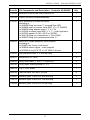
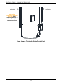
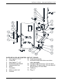
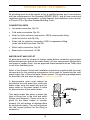
Installation Instructions Solar Controller Kit (Part Number 299280) This solar controller kit must be installed and serviced by a qualified person. Please leave this guide with the householder. The solar water heater and its components are covered by a manufacturer’s warranty. For full manufacturer’s warranty details, refer to the Owners Guide and Installation Instructions supplied with the solar storage tank. RHEEM AUSTRALIA PTY LTD - ABN 21 098 823 511 1 Alan Street Rydalmere NSW 2116 Australia (PO Box 7508 Silverwater NSW 2128) SOLAHART INDUSTRIES PTY LTD - ABN 45 064 945 848 112 Pilbara Street Welshpool WA 6106 Australia PATENTS This water heater may be protected by one or more patents or registered designs in the name of Rheem Australia Pty Ltd. ® TRADEMARKS Registered trademark of Rheem Australia Pty Ltd. ™ Trademark of Rheem Australia Pty Ltd. Note: Every care has been taken to ensure the accuracy in preparation of this publication. No liability can be accepted for any consequences, which may arise as a result of its application. CONTENTS HOUSEHOLDER - This installation instruction booklet is intended for the installer but you may find it of interest. Installation – Solar Control Unit .................................................4 Connections – Plumbing ..........................................................10 Connections – Electrical ...........................................................12 Solar Controller And Solar Monitor .........................................13 3 INSTALLATION – SOLAR CONTROL UNIT SOLAR CONTROLLER KIT The solar water heater is designed for the solar collectors to be roof mounted and the solar storage tank to be installed at ground or floor level. This solar controller kit is designed to be mounted on the side of the solar storage tank incorporating a raised solar hot water inlet. The solar control unit governs the operation of the solar water heater. For full details on the installation of the solar storage tank, the cold water plumbing supply details and electrical connections to the tank, refer to the Owners Guide and Installation Instructions supplied with the solar storage tank. The Owners Guide also contains consumer information on the operation of the solar water heater system. SOLAR CONTROL UNIT The solar control unit is designed to be mounted on the side of the solar storage tank, with its location above and offset from the solar cold water outlet. The solar control unit, supplied with a 1.8 metre power cord, requires a 240 V 50 Hz general purpose outlet (GPO) located within 1.2 metres of its installation. The GPO must have a continuous power supply originating from a circuit other than the water heater circuit. The GPO is required to be weatherproof if installed outdoors (refer to “Connections – Electrical” on page 12). The solar control unit automatically controls the flow rate through the collector circuit. This is achieved via the hot and cold sensors and differential controller programming providing control over the operation of the circulator. There is no provision for nor is adjustment to the solar control unit required. Notes: Care must be taken when mounting the solar control unit to the side of the solar storage tank. If the cylinder is damaged as a result of mounting the solar control unit to the jacket, any resultant faults will not be covered by the manufacturer’s warranty (refer to “Saddling - Pipe Work” on page 11). All pipe work must be purged and cleared of foreign matter before connection and before attempting to operate the water heater. It is important to connect the solar cold and solar hot pipes to the correct connections at the solar storage tank. Connect the solar pipes to the solar storage tank using only the fittings supplied. All olive compression fittings must use brass or copper olives. Use approved thread sealant such as Teflon tape on all other threaded joints. 4 INSTALLATION – SOLAR CONTROL UNIT Part No Kit Components and Description - Controller Kit 299280 Qty 126554 Installation instructions solar controller kit 1 052134 Control unit solar pumped assembly 1 220345 Valve assembly air bleed and check consisting of: 1 x 088058 fitting tee brass ½” screwed Rye 4203 1 x 088880 solar non-return valve RMC ½” x ¾” SNR505 1 x 088069 fitting adaptor brass 1” F x ½” M 1 x 220344 air bleed valve RMC ½” x 1” – solar high temp 1 x 087033 washer 30 OD x 20 ID x 2 EPDM 1 x 088119 fitting nut compression ½” Rye 10090 1 x 088027 fitting olive compression brass ½” 1 088064 Sensor tee / nipple assembly solar pumped consisting of: 1 x 088061 tee 3 way / cold sensor 1 x 088062 sensor nipple – solar pumped 1 x 087026 O ring 5/16” ID x 1/16” BS011 silicone 1 223603 Pipe preformed tube ½” x 400 mm long 1 080031 Screws No 8 x 13 mm 4 088063 Fitting union male ½” M x ½” C Rye 4910 3 088143 Fitting nipple reducing brass ¾” x ½” 1 080079 Plug ½” BSP brass 1 080228 Cable tie black 250 mm x 4.8 mm 6 180081 Insulation pipe 13 mm ID x 400 mm long 1 180072 Insulation pipe 35 mm ID x 150 mm long 1 180082 Insulation pipe 35 mm ID x 50 mm long 1 5 INSTALLATION – SOLAR CONTROL UNIT SOLAR STORAGE TANK WITH RAISED SOLAR HOT INLET Numbers in parentheses refer to items on diagram on page 9. Note: The solar control unit automatically controls the flow rate through the collector circuit. This is achieved via the hot and cold sensors and differential controller programming providing control over the operation of the circulator. There is no provision for nor is adjustment to the solar control unit required. To connect the solar cold pipe and mount the solar control unit on a solar storage tank with a raised solar hot inlet (and raised heating unit): Assemble a ½” x ½” hex nipple (1) into the branch outlet of the 4 way tee (2) (ensure the compression end of the nipple is exposed) and the ½” x ¾” hex nipple (3) in the end of the 4 way tee, so that when the assembly is fitted to the cold water inlet of the solar storage tank, the compression nipple (1) is orientated vertically upwards and the cold sensor housing is orientated to the rear of the solar storage tank. Fit the assembly to the solar cold water outlet of the solar storage tank. Ensure the compression nipple (1) is orientated vertically upwards and the cold sensor housing is orientated to the rear of the solar storage tank. Fit the ½”plug (15) into the end of the 4 way tee. Connect the DN15 preformed pipe (4) to the branch tee connection, using the compression nut (5) and olive (6) provided, ensuring the longer straight end is orientated upwards. Insulate the preformed pipe (4) with the 400 mm long x 13 mm diam insulation (12) provided, ensuring the insulation is pushed down the full length of the pipe. Locate the solar control unit (8) by connecting the DN15 preformed pipe (4) to the nipple on the inlet of the circulator (7) using the compression nut (5) and olive (6) provided. Secure the solar control unit (8) to the solar storage tank using the four screws (9) provided. Fit a ½” x ½” hex nipple (1) to the outlet of the circulator (7) mounted in the solar control unit (8) (ensure the compression end of the nipple is exposed). Connect the solar cold pipe (to the collector) to the nipple (1) on the outlet side of the circulator (7) using the compression nut (5) and olive (6) provided. Insert the cold sensor probe (10) into the cold sensor housing on the 4 way tee (2), ensuring the ‘O’ ring is in position on the probe. Lock it into position with the locking washer and clip provided. Connect the hot sensor lead (from the solar collector installation) to the hot sensor cable connector at the underside of the solar control unit (8). 6 INSTALLATION – SOLAR CONTROL UNIT If this installation utilises selective surface collectors, it may be necessary to use the short sensor lead adaptor, which is supplied taped to the plastic bag containing the hot sensor in the roof kit, to enable the mating of the connections. If the short sensor lead adaptor is not required it can be discarded. Note: Ensure the hot sensor lead is not in direct contact with the solar hot or solar cold pipe work at any point of the collector circuit, otherwise damage to the sensor lead can occur due to the high temperatures which can be experienced within the pipe work. Damage to the hot sensor lead can result in solar gain not being achieved and the freeze protection system being rendered inoperative. The hot sensor lead may be cable tied to the outside of the insulation on the solar pipe work. To connect the solar hot pipe to the solar storage tank: Insulate the solar non-return valve of the air bleed valve and solar non-return valve assembly (11) with the 50 mm long x 35 mm diam insulation (13) provided. Fit the air bleed valve and solar non-return valve assembly (11) to the solar hot water inlet of the solar storage tank. Ensure the bleed valve outlet is pointing vertically downwards. Connect a DN15 copper drain line to the bleed valve, to carry the discharge clear of the water heater and solar control unit, using the compression nut and olive provided (refer to “Bleed Valve Drain” page 11). Fit a ½” x ½” hex nipple (1) to the exposed end (inlet) of the air bleed valve and solar non-return valve assembly (11) (ensure the compression end of the nipple is exposed). Connect the solar hot pipe (from the collector) to the nipple (1) on the air bleed valve and solar non-return valve assembly (11) using the compression nut (5) and olive (6) provided. Insulate the tee and bleed valve, from the solar hot pipe to the drain line of the bleed valve, with the 150 mm long x 35 mm diam insulation (13) and secure with the cable ties (14) provided. Insulate the drain line from the bleed valve with closed cell polymer insulation or similar (minimum thickness 13 mm). The insulation must be weatherproof and UV resistant if exposed. 7 INSTALLATION – SOLAR CONTROL UNIT from solar collectors to solar collectors refer to the installation diagram on page 9 for assembly details of solar cold and hot pipe connections Solar Storage Tank with Control Unit c Boost Single Element - Solar Installation Schemati 8 INSTALLATION – SOLAR CONTROL UNIT SUPPLIED IN SOLAR CONTROL UNIT KIT (299280) 1. 2. 3. 4. 5. 6. 7. 8. 9. Hex nipple ½” X ½” 4 way tee Hex nipple ½” x ¾” Preformed pipe DN15 Compression nut Olive Circulator Solar control unit Screws 10. Cold sensor probe 11. Air bleed valve and solar non-return valve assembly 12. Insulation 400 mm long x 12 mm diam 13. Insulation 150 mm long x 35 mm diam & 50 mm long x 35 mm diam 14. Cable tie 15. Plug ½” Solar Direct Pumped Electric Boosted Models Single Element 9 Solar Control Unit Installation (exploded view) CONNECTIONS – PLUMBING All plumbing work must be carried out by a qualified person and in accordance with the requirements of the Standard AS/NZS 3500.4, and all local codes and regulatory authority requirements. In New Zealand, the installation must conform to Clause G12 of the New Zealand Building Code. CONNECTION SIZES Hot water connection: Rp 3/4. Cold water connection: Rp 3/4. Solar hot (from collector) connection: DN15 compression fitting. (solar hot inlet to tank Rp 3/4) Solar cold (to collector) connection: DN15 compression fitting. (solar cold outlet from tank: Rp 3/4) Relief valve connection: Rp 3/4. Bleed valve connection: G1.0B. WATER INLET AND OUTLET All pipe work must be cleared of foreign matter before connection and purged before attempting to operate the water heater. All olive compression fittings must use brass or copper olives. Use an approved thread sealant such as Teflon tape on all other threaded joints. Refer to the Owners Guide and Installation Instructions supplied with the solar storage tank for the plumbing arrangement to be used for connecting the cold water supply line to the solar water heater system. The plumbing arrangements for the solar cold and solar hot pipes are shown on page 9. A disconnection union must always be provided at the cold water inlet, solar cold water outlet, solar hot water inlet and hot water outlet on the water heater to allow for disconnection of the water heater. This water heater has either a plastic dip tube or fitting liner in the inlet and outlet fittings (see diagram). These must be in place for the water heater to function properly. Do not remove or damage them by using heat nearby. They will be pushed into the correct position as the fitting is screwed in. 10 CONNECTIONS – PLUMBING BLEED VALVE DRAIN A copper drain line must be fitted to the bleed valve to carry the discharge clear of the water heater and solar control unit. Connect the drain line to the bleed valve using a disconnection union. The pipe work from the bleed valve to the drain should be as short as possible and fall all the way from the valve with no restrictions. It should have no more than three right angle bends in it. Use DN15 pipe. The outlet of the drain line must be in such a position that flow out of the pipe can be easily seen (refer to AS/NZS 3500.4) - but arranged so water discharge will not cause injury, damage, nuisance or splashing. The water discharged may be of a high temperature and even very high temperature steam can be generated under certain conditions. The drain line must be fully insulated with closed cell polymer insulation or similar (minimum thickness 13 mm). The insulation must be weatherproof and UV resistant if exposed. Warning: The solar collectors can generate very high temperature water and even very high temperature steam can be generated under certain conditions when the bleed valve is opened. It is strongly recommended pipe work downstream of the bleed valve be capable of carrying water exceeding 93°C. Failure to observe this precaution may result in damage to pipe work and property. SADDLING - PIPE WORK To prevent damage to the cylinder when attaching pipe clips or saddles to the water heater jacket, we recommend the use of self-drilling screws with a maximum length of 13 mm. Should pre drilling be required extreme caution must be observed when penetrating the jacket of the water heater. Note: If the cylinder is damaged as a result of attaching pipe clips or saddles to the jacket, any resultant faults will not be covered by the manufacturer’s warranty. 11 CONNECTIONS – ELECTRICAL The power supply to the water heater must not be switched on until the water heater is filled with water and a satisfactory megger reading is obtained. All electrical work and permanent wiring must be carried out by a qualified person and in accordance with the Wiring Rules AS/NZS 3000 and all local codes and regulatory authority requirements. The solar control unit, supplied with a 1.8 metre power cord, requires a switched 240 V AC 50 Hz general purpose outlet (GPO) to be located within 1.2 metres of the installation. The GPO must have a continuous power supply originating from a circuit other than the water heater circuit. The GPO is required to be weatherproof if installed outdoors. The GPO to the solar control unit must be switched on for the solar control system to operate and solar gain to be achieved. The solar control unit automatically controls the flow rate through the collector circuit. This is achieved via the hot and cold sensors and differential controller programming providing control over the operation of the circulator. There is no provision for nor is adjustment to the solar control unit required. If the power supply cord or plug is damaged, it must be replaced by a qualified person in order to avoid a hazard. The power supply cord and plug must be replaced with a genuine replacement part available from the manufacturer. 12 SOLAR CONTROLLER AND SOLAR MONITOR SOLAR MONITOR A solar monitor is located on the side of the solar control unit and houses a green and a red LED. The green LED, marked “Solar”, indicates the current operational mode of the solar water heater and the red LED, marked “Attention”, may indicate a potential fault mode. The green LED will emit either a constant glow, a constant pulsing or a series of flashes, with a 2 second interval between each series. The red LED will emit either a constant glow, a constant pulsing or a series of flashes with a 2 second interval between each series. A constant glow or pulsing does not necessarily mean there is a fault with the system. A series of flashes indicates there may be a particular fault condition with the system. DIAGNOSTIC FEATURES OF THE SOLAR CONTROLLER The operational modes are: Flashes Operational Modes solid green Standby mode (remains on) Flashes Indicator or Fault Modes Solid red Hot sensor temperature (remains on) greater than 130°C green slow pulse Standby mode (power on for less than 48 hours) green rapid pulse Circulating water through collectors 3 x red Hot sensor in collector – short circuit 3 x green Circulating water through collectors (power on for less than 48 hours) 4 x red Hot sensor in collector – open circuit 5 x red Cold sensor –short circuit 6 x red Cold sensor – open circuit red rapid pulse no green Power outage or call for (remains off) service 13 Temperature rise across collector greater than 45°C (circulator at full speed) SOLAR CONTROLLER AND SOLAR MONITOR If the power supply to the solar control unit is on and the green LED is off or the red LED is flashing, this indicates there may be a fault with the water heater. The red LED may emit from three to six flashes in each series of flashes. A constant glow or pulsing of the red LED does not necessarily mean there is a fault with the system. Notes: If the system is in standby mode with the green LED emitting either a constant glow or slow pulsing flashes (circulator is off) and the solar storage tank is full of hot water, the red LED may simultaneously emit a constant glow if solar radiation is still being received by the solar collectors. This does not indicate a fault. The red LED will go out when the temperature in the solar collectors decreases. During periods of high solar radiation and the circulator activates after having been off (the green LED will emit either a rapid pulse or a series of three flashes), such as during start up if the solar collectors have not been covered, it is possible the red LED may simultaneously emit a rapid pulse for a period of up to ten (10) minutes. This does not indicate a fault. Refer to “Commissioning” on page 14 for the possible green and red LED flashing sequence during start up procedure. If the red LED continues to emit a rapid pulse for longer than ten (10) minutes, or emits a series of flashes, then count the number of flashes and phone your nearest Service Department or Accredited Service Agent to arrange for an inspection. COMMISSIONING Refer to the installation instructions supplied with the solar storage tank for the complete commissioning procedure. When the electrical supply is switched on to the solar control unit at start up: If there is no solar gain, the circulator will not activate and the green LED will emit a slow pulse. The slow pulse indicates the circulator is not activated and the power to the solar control unit has been on for less than 48 hours. If there is solar gain, the circulator activates and the green LED will emit a series of three (3) flashes. The three (3) flashes indicate the circulator is operating and power to the solar control unit has been on for less than 48 hours. 14 SOLAR CONTROLLER AND SOLAR MONITOR The circulator will operate at full speed for approximately fifteen (15) seconds. After fifteen (15) seconds, the solar controller will commence to pulse the circulator to reduce the flow rate through the collector circuit. This will increase the temperature rise across the solar collectors and assist in maximising the system efficiency for the available solar energy. It is normal operation for the circulator to experience a pulsing effect. The red LED may emit a rapid pulse for a short period (whilst the green LED is emitting a series of three (3) flashes), particularly if the solar collectors were left uncovered during the final stages of the installation and commissioning procedure. This indicates a temperature difference between the hot sensor and cold sensor of greater than 45°C and does not represent a fault code. This is the result of a build-up of heat and increase in water temperature in the solar collectors prior to the switching on of the electrical supply to the solar control unit. The rapid pulsing of the red LED will cease as the water circulates and the heat is dissipated from the solar collectors. This should be within four (4) to five (5) minutes of start up, but may take up to ten (10) minutes. Whilst the red LED is emitting a rapid pulse, the circulator will operate at full speed. After the red LED has extinguished, the solar controller will commence to pulse the circulator to reduce the flow rate through the collector circuit. If the red LED does continue to emit a rapid pulse for longer than ten (10) minutes, this may indicate water is not circulating through the solar collectors and collector circuit: switch off the electrical supply at the power outlet to the solar control unit repeat the procedure to bleed the solar collectors Refer to the Owners Guide and Installation Instructions supplied with the solar storage tank. switch on the electrical supply at the power outlet to the solar control unit. 15 Revision Date: 2014 December 126554H 16