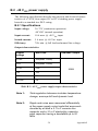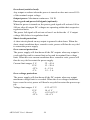
1
AWS-8248V
Industrial Workstation with 15"
LCD Display
User’s Manual
Copyright
This document is copyrighted September, 2002, by Advantech Co., Ltd.
All rights are reserved. Advantech Co., Ltd. reserves the right to make
improvements to the products described in this manual at any time. Specifications are thus subject to change without notice.
No part of this manual may be reproduced, copied, translated, or transmitted in any form or by any means without the prior written permission of
Advantech Co., Ltd. Information provided in this manual is intended to
be accurate and reliable. However, Advantech Co., Ltd., assumes no
responsibility for its use, nor for any infringements upon the rights of
third parties which may result from its use.
Acknowledgements
AWS-8248VT, AWS-8248VTP, AWS-8248VT-T, and AWS-8248VTP-T
are all trademarks of Advantech Co., Ltd. IBM and PC are trademarks of
International Business Machines Corporation. MS-DOS is a trademark of
Microsoft Corporation. All other brand and product names mentioned
herein are trademarks or registered trademarks of their respective owners.
Printed in Taiwan
AWS-8248V User’s Manual
ii
September 2002
FCC Class A
This equipment has been tested and found to comply with the limits for a
Class A digital device, pursuant to Part 15 of the FCC Rules. These limits
are designed to provide reasonable protection against harmful interference when the equipment is operated in a commercial environment. This
equipment generates, uses and can radiate radio frequency energy. If not
installed and used in accordance with this user's manual, it may cause
harmful interference to radio communications. Operation of this equipment in a residential area is likely to cause harmful interference, in which
case the user will be required to correct the interference at his own
expense.
iii
Packing List
Before you set up the AWS-8248V, make sure that the following items
have been included in your package, and that this manual is in good condition. If anything is missing or damaged, contact your dealer immediately:
•
•
One AWS-8248V industrial workstation with 15" flat panel display
One accessory box, including:
- One power cord
- One keyboard transfer cable
- One CD-R for IC & HMI products Driver/manual
- Flat gray cable for 3.5" HDD and slim CD-ROM
- RS-232 cable to link touchscreen to CPU card (for -T models only)
- Screw bag with screwsIf any of these items is missing or damaged, contact your distributor or sales
representative immediately.
Additional Information and Assistance
1.Visit the Advantech web site at www.advantech.com where you can
find the latest information about the product.
2.Contact your distributor, sales representative, or Advantech's customer
service center for technical support if you need
additional assistance. Please have the following information ready before
you call:
•Product name and serial number
•Description of your peripheral attachments
•Description of your software (operating system, version, application
software, etc.)
•A complete description of the problem
•The exact wording of any error messages
AWS-8248V User’s Manual
iv
Safety Instructions
1. Read these safety instructions carefully.
2. Keep this User's Manual for later reference.
3. Disconnect this equipment from any AC outlet before cleaning. Use a damp
cloth. Do not use liquid or spray detergents for cleaning.
4. For plug-in equipment, the power outlet socket must be located near the
equipment and must be easily accessible.
5. Keep this equipment away from humidity.
6. Put this equipment on a reliable surface during installation. Dropping it or letting it fall may cause damage.
7. The openings on the enclosure are for air convection. Protect the equipment
from overheating. DO NOT COVER THE OPENINGS.
8. Make sure the voltage of the power source is correct before connecting the
equipment to the power outlet.
9. Position the power cord so that people cannot step on it. Do not place anything
over the power cord.
10. All cautions and warnings on the equipment should be noted.
11. If the equipment is not used for a long time, disconnect it from the power
source to avoid damage by transient overvoltage.
12. Never pour any liquid into an opening. This may cause fire or electrical shock.
13. Never open the equipment. For safety reasons, the equipment should be
opened only by qualified service personnel.
14. If one of the following situations arises, get the equipment checked by service
personnel:
a. The power cord or plug is damaged.
b. Liquid has penetrated into the equipment.
c. The equipment has been exposed to moisture.
d. The equipment does not work well, or you cannot get it to work according
to the user's manual.
e. The equipment has been dropped and damaged.
f. The equipment has obvious signs of breakage.
15. DO NOT LEAVE THIS EQUIPMENT IN AN ENVIRONMENT WHERE
THE STORAGE TEMPERATURE MAY GO BELOW -20° C (-4° F) OR
ABOVE 60° C (140° F). THIS COULD DAMAGE THE EQUIPMENT. THE
EQUIPMENT SHOULD BE IN A CONTROLLED ENVIRONMENT.
The sound pressure level at the operator's position according to IEC 704-1:1982 is
no more than 70dB (A).
DISCLAIMER: This set of instructions is given according to IEC 704-1. Advantech disclaims all responsibility for the accuracy of any statements contained
herein.
v
Wichtige Sicherheishinweise
1. Bitte lesen sie Sich diese Hinweise sorgfältig durch.
2. Heben Sie diese Anleitung für den späteren Gebrauch auf.
3. Vor jedem Reinigen ist das Gerät vom Stromnetz zu trennen. Verwenden Sie
Keine Flüssig-oder Aerosolreiniger. Am besten dient ein angefeuchtetes Tuch
zur Reinigung.
4. Die NetzanschluBsteckdose soll nahe dem Gerät angebracht und leicht
zugänglich sein.
5. Das Gerät ist vor Feuchtigkeit zu schützen.
6. Bei der Aufstellung des Gerätes ist auf sicheren Stand zu achten. Ein Kippen
oder Fallen könnte Verletzungen hervorrufen.
7. Die Belüftungsöffnungen dienen zur Luftzirkulation die das Gerät vor überhitzung schützt. Sorgen Sie dafür, daB diese Öffnungen nicht abgedeckt werden.
8. Beachten Sie beim. AnschluB an das Stromnetz die AnschluBwerte.
9. Verlegen Sie die NetzanschluBleitung so, daB niemand darüber fallen kann.
Es sollte auch nichts auf der Leitung abgestellt werden.
10. Alle Hinweise und Warnungen die sich am Geräten befinden sind zu
beachten.
11. Wird das Gerät über einen längeren Zeitraum nicht benutzt, sollten Sie es vom
Stromnetz trennen. Somit wird im Falle einer Überspannung eine Beschädigung vermieden.
12. Durch die Lüftungsöffnungen dürfen niemals Gegenstände oder Flüssigkeiten
in das Gerät gelangen. Dies könnte einen Brand bzw. elektrischen Schlag auslösen.
13. Öffnen Sie niemals das Gerät. Das Gerät darf aus Gründen der elektrischen
Sicherheit nur von authorisiertem Servicepersonal geöffnet werden.
14. Wenn folgende Situationen auftreten ist das Gerät vom Stromnetz zu trennen
und von einer qualifizierten Servicestelle zu überprüfen:
a - Netzkabel oder Netzstecker sind beschädigt.
b - Flüssigkeit ist in das Gerät eingedrungen.
c - Das Gerät war Feuchtigkeit ausgesetzt.
d - Wenn das Gerät nicht der Bedienungsanleitung entsprechend funktioniert
oder Sie mit Hilfe dieser Anleitung keine Verbesserung erzielen.
e - Das Gerät ist gefallen und/oder das Gehäuse ist beschädigt.
f - Wenn das Gerät deutliche Anzeichen eines Defektes aufweist.
Der arbeitsplatzbezogene Schalldruckpegel nach DIN 45 635 Teil 1000
beträgt 70dB(A) oder weiger.
DISCLAIMER: This set of instructions is given according to IEC704-1.
Advantech disclaims all responsibility for the accuracy of any statements
contained herein.
AWS-8248V User’s Manual
vi
Contents
Chapter
1 Introduction ......................................................2
1.1
Introduction ....................................................................... 2
1.1.1
1.2
1.3
1.4
Chapter
Features:.......................................................................... 3
Specifications .................................................................... 3
Front and rear panel layout................................................ 5
Dimensions........................................................................ 6
2 System Setup.....................................................8
2.1
2.2
General .............................................................................. 8
Rack mounting .................................................................. 9
2.3
Panel mounting................................................................ 10
Figure 2.1:Rack mounting the AWS-8248 ..................... 9
Figure 2.2:Panel mounting the AWS-8248................... 10
Chapter
3 Programming KBT-2002 Macro Keys .........14
3.1
3.2
3.3
3.4
Introduction ..................................................................... 14
Macro keys ...................................................................... 14
Using Main.exe to edit Macro Key ................................. 14
Examples ......................................................................... 15
Appendix A
Display Timing Mode and OSD ...................22
A.1
Supported Input Timing Modes ...................................... 22
A.2
A.3
OSD Operation Keypad .................................................. 24
OSD function and operation............................................ 25
Table A.1:Display Modes Table................................... 22
Figure A.1:OSD menu .................................................. 25
Table A.3:OSD Functionality ....................................... 26
Appendix B
Power Supply Specifications ........................28
B.1
Supported Input Timing Modes ...................................... 28
B.1.1
B.2
B.2.1
B.3
Specifications................................................................ 28
-48 V DC power supply .................................................. 29
Specifications................................................................ 29
Table B.1:-48 VDC power supply output
characteristics ..................... 29
Table B.2:-48 VDC power supply DC output wire list 32
24 VDC power supply..................................................... 33
B.3.1
Table B.3:24VDC power supply output load range .... 33
General features ............................................................ 34
Appendix C
Optional Touchscreen...................................38
C.1
C.2
Specifications .................................................................. 38
Installation of Touchscreen Driver.................................. 39
vii
AWS-8248V User’s Manual
viii
CHAPTER
Introduction
• Introduction
• Specifications
• Front and rear panel layout
• Dimensions
1
Chapter 1 Introduction
1.1 Introduction
The AWS-8248V is a 14-slot, 15” TFT LCD workstation. It is a great
update to the AWS-8248 product line by offering more expansion capability, a larger LCD screen, and increased usability, all at an even more
competitive price. The AWS-8248V also provides an additional major
feature for users: Easy maintenance. Using three card-cages and thumbscrew fasteners, the AWS-8248V makes maintenance quick and easy.
The AWS-8248V combines multiple slots and 15” LCD in a more cost
effective and easier to maintain design.
Easy-to-maintain: Three card-cage and thumbscrew fasteners
The AWS-8248V's "work drawer" designed card cage conveniently
slides out for easy access. These three card-cages (one drawer previously)
allow add-on cards, HDD/CD-ROMs and power supplies to be easily
changed or added. It only takes a few minutes to service the unit, saving
time and money while reducing downtime. The thumbscrew fasteners
make access fast and easy, speeding maintenance procedures.
Easy access control panel
Users can easily access the AWS-8248V's controls from the front of the
unit via a sturdy protective door. Controls include LEDs and switches for
power and system reset, as well as an OSD in front. The front panel also
holds a 3¾" 1.44 MB FDD. The aluminum door protects controls from
the environment. The door has a waterproof foam-rubber seal and retaining hand screw to securely hold it closed. In addition, the door offers protection against accidental operation of the unit's controls.
Industrial design meets harsh environment needs
In addition, the AWS-8248V also features many powerful functions that
meet or exceed industrial-grade requirements. The front panel is made of
aluminum, which prevents the panel from being damaged by acid, salt
and other elements. The unit is also waterproof and IP65/ NEMA4 compliant. The AWS-8248V provides three mounting configurations to fit
various applications: 19" rack mount, panel mounting and desktop.
AWS-8248V User’s Manual
2
1.1.1 Features:
• Low cost 15", 14-slot TFT LCD workstation, and 1024 x 768 resolution
• Three card-cage design: Easy to maintain add-on cards, CPU card and
power supply.
• Two 3.5î HDDs with mobile rack drive & CD-ROM drive in back of
chassis
• Equipped with the On-Screen Display (OSD) operation keypad on the
front panel
• IP65/NEMA 4, Aluminum panel.
1.2 Specifications
General
• Construction: Heavy-duty aluminum and steel chassis
• Disk drive housing: Holds one 3½" FDD, one CD-ROM and two
3½" HDD (CD-ROM and HDD optional)
• Cooling system:
- One 32 CFM fan (flow out) on rear panel for power supply
• Dimensions:
- Width: 482 mm (19.0")
- Depth: 450 mm (17.7")
- Height: 356 mm (14.0")
• Weight: 20 kg (44 lbs)
LCD Display
- Display type: 15" TFT LCD
- Max. resolution: 1024 x 768
- Maxi. colors: 262K
- Luminance (cd/m2): 200
- Viewing angle: 100°(H), 120°(V)
- Operating temperature: 0 ~ 50°C (32 ~ 122° F)
- LCD MTBF: 50,000 hours
3
Chapter 1
- Backlight lifetime: 50,000 hours
- Interface: Direct VGA
- LCD defect specification: refer to Advantech web site
Front Panel
• Keypads: One with 39 operating keys, one with 10 function keys
and 10 programmable macro function keys
• Keyboard connector: Pre-wired 5-pin DIN connector with dustprotection cover on front and rear panel
• Switches: Reset and power on/off.
Passive backplane
• AWS-8248VT & AWS-8248VT-T:
14 ISA slot passive backplane
• AWS-8248VTP & AWS-8248VTP-T:
9 ISA / 4 PCI / 1 CPU slot passive backplane
Power supply
• AC input: 250 W (standard offer)
• Input voltage:
95 ~ 132 VAC or 190 ~ 264 VAC , switchable
• Output voltage:
+3.3V@20A, +5 V @ 27 A; +12 V @ 13 A; -5 V @ 0.3 A; -12 V @
0.8 A
• MTBF: 100,000 hours
• Safety: UL/CSA/TUV
-48 VDC input 250 W (optional)
• Input voltage: -36 ~ -72 VDC
• Output voltage:
+3.3V@25A, +5 V @ 30 A; +12 V @ 12 A; -5 V @ 0.5 A; -12 V @
1.0 A
• MTBF: 100,000 hours
AWS-8248V User’s Manual
4
24 VDC input 250 W (optional)
• Input voltage: 19 ~ 32 VDC
• Output voltage:
+5 V @ 25 A; +12 V @ 10 A; -5 V @ 1.0 A; -12 V @ 1.0 A
• MTBF: 100,000 hours
Environmental specifications
• Operating temperature: 0 ~ 50° C (32 ~ 122° F)
• Relative humidity: 5 ~ 85% @ 40° C, non-condensing
• Vibration: 5 ~ 17 Hz, 0.1" double-amplitude displacement 17 ~
500 Hz, 1.0 G peak to peak.
1.3 Front and rear panel layout
Figure 1.1: Front panel layout
5
Chapter 1
Figure 1.2: Rear panel layout
1.4 Dimensions
Figure 1.3: AWS-8248 dimensions
AWS-8248V User’s Manual
6
CHAPTER
2
System Setup
• General
• Rack Mounting
• Panel mounting
Chapter 2 System Setup
2.1 General
When you receive your workstation you will find a backplane, power
supply, and floppy disk drive already installed. Further setup of the
AWS-8248V is easy. All you have to do is slide out its work drawer module, install a CPU card, optional hard disk drive and whatever additional
I/O cards your application requires.
Warning!
1. Do not begin your installation until you are
sure there is no power flowing within the AWS8248V. Power must be switched off and the
main power cord unplugged.
2. Every time you service the AWS-8248V, you
should switch the power off and unplug the
main power cord.
AWS-8248V User’s Manual
8
2.2 Rack mounting
The AWS-8248 can be mounted in a 19" rack. Ensure that all addi-tional
equipment has been installed correctly and that the cabling has been reattached. (See Fig. 2-7) Remove the screw covers on the front panel. Attach
the case to the rack using screws on both sides.
Figure 2.1: Rack mounting the AWS-8248
9
Chapter 2
2.3 Panel mounting
Panel mounting the AWS-8248 is easy. Just line up the holes in the panel
aperture and the holes on the panel, and then secure the AWS-8248 to the
panel with the mounting bolts.
Figure 2.2: Panel mounting the AWS-8248
AWS-8248V User’s Manual
10
CHAPTER
3
Programming KBT-2002
Macro Keys
• Introduction
• Macro Keys
• Using Main.exe to edit Macro Key
• Examples
Chapter 3 Programming KBT-2002
Macro Keys
3.1 Introduction
The KBT-2002 is equipped with programmable function keys (macro
keys) that greatly enhances the operating interface. Macros, which are far
more powerful than batch files; automate the most commonly used input
sequences. They extend their functional reach within application programs.
3.2 Macro keys
Macro keys (SF1 , SF2 ,...SF10)
Ten programmable macro keys are located on the front panel of the workstation.
Macro keys (SF11 , SF12 ,...SF30)
These twenty programmable macro keys are customized models. If your
workstation doesn’t have these twenty keys, you do not need to edit SF 11
to SF 30 when using the utility program, Main.exe, to edit the macro
keys.
The limitation of editing the macro keys
When editing the macro keys, the number of characters is limited to 78.
Every ten macro keys are defined as one block; there are three blocks in
total. The size of each block is limited under 256 bytes. Please refer to the
next section for editing the macro keys.
3.3 Using Main.exe to edit Macro Key
First, copy all the files to your hard disk and/or make a backup disk. Take
a look at the content of the utility disk; please find the .pad file that corresponds to your workstation, for example, AWS8420.pad. Remember this
file name, because you will need it to edit the macro keys.
AWS-8248V User’s Manual
14
There ís an example within the subdirectory of the utility disk. Go into
this subdirectory and look for a .txt file that corresponds to your workstation, for example, AWS8420.txt. You can use this file under the macro
key edit program to practice.
Note 1:
The keyboard translator utility main.exe program can be run under DOS mode only.
Note 2:
The following windows illustrations are examples only. You must follow the instruction and
pay attention to the instructions which appears
on you screen.
3.4 Examples
Boot your workstation and enter the DOS command. Key in main.exe and
press the enter key. You will see the following screen.
15
Chapter 3
Choose Load in the function and press the enter key. Key in the file name
that you edited in this program before. To practice, you can choose, for
example, the AWS8420.txt in the example in the utility disk. After reading the file, press Esc key to leave this mode.
Whether you have loaded the old file or not, choose Edit in the main
menu and press enter to go into the edit mode. You can see the operating
guide at the bottom of the screen. Use the up/down arrow keys to move
the cursor, and page up/page down keys to change pages. These keys help
you to choose the macro keys that you want to edit. The SF01, SF02, and
etc represent the macro keys. They are called the macro key number.
After picking the macro keys you want to edit, press the enter key to go
into a sub screen.
AWS-8248V User’s Manual
16
n this sub screen, you can key in any character string that you want to see
when pressing this macro key, or any signs. You can also key in the
names of the function keys of the keyboard; but please add a [ ] sigh. The
number characters you key in should be under 78. After editing, press Esc
key to go back to the edit mode, then you can choose other macro keys to
edit. If there is no SF 11, SF1 2,...SF30 on your workstation, please
ignore and do not edit them. Upon completing the edit, press ESC key to
leave the edit mode. You can see that there is no red bars on the macro
keys you’ve edited. Choose Save in the main menu and press enter key.
You will see a sub-screen like this. Please key in a file name; the total
number of the character used should be under 7. After keying in the file
name, press Enter; the system will save it with .txt and leave the Save
mode.
17
Chapter 3
Choose Run in the main menu, and press Enter to go into the Run (programming) mode. You will see a sub-screen for upper key setting OFF=
Press both character and upper key in the same time ON= Press upper
key. Then key the character for upper layer. Press the upper key again for
the lower layer PS: some membrane keypad has Upper indicator (light
on=upper status)
After setting the upper key, press Enter. Choose if you need the beep
sound when you press the macro keys. OFF = no beep sound ON = with
beep sound
AWS-8248V User’s Manual
18
After the beep sound setting, press Enter and you will be asked to key in a
.pad file name. Please refer to chapter 1.3. Do not use any other file
names other than that of this workstation, or character definition errors
might arise!
After keying the file name, press Enter, The system will start to read the
data in the file together with the data in the .txt file that you just edited
and save to the keyboard translator board of this workstation.
19
Chapter 3
After the system finished the programming, you will see a sub-screen that
tells you to repeat the process again or press Esc to leave the Run mode.
Note:
There might be transition error when the connection cable between the CPU card and the
keyboard translator is too long. If the error
occurs, please turn off the workstation and use
a shorter cable, then reboot the workstation and
run the main.exe program again.
AWS-8248V User’s Manual
20
Appendix
A
Display Timing Mode &
OSD
• Supported input timing modes
• OSD operation keypad
• OSD function and operation
Appendix A Display Timing Mode and OSD
A.1 Supported Input Timing Modes
The following nineteen kinds of timings have already been programmed
in this module. The input synchronous signals are automatically recognized.
Table A.1: Display Modes Table
Chroma
Resolution
2325
Timing No.
HSYNC /
KHz (+/-)
VSYNC /
Hz (+/-)
PIXEL
RATE /
MHz
#008
VGA
640 * 350
31.469 (+)
70.087 (-)
25.175
#011
VGA
640 * 400
31.469 (-)
70.087 (+) 25.175
#013
VGA
640 * 480
31.469 (-)
59.941 (-)
25.175
#016
VGA
720 * 350
31.469 (-)
70.087 (-)
28.322
#019
VGA
720 * 400
31.469 (-)
70.087 (+) 28.322
#032
VESA 640
* 400
37.861 (-)
84.136 (+) 31.500
* #034
and #074
#033
VESA 640
* 480
37.861 (-)
72.810 (-)
* #076
#034
VESA 720
* 400
37.736 (-)
84.045 (+) 36.000
* #032
and #074
#035
VESA
800-5
35.156 (+)
56.250 (+) 36.000
* #066
#036
VESA
800-6
37.879 (+)
60.317 (+) 40.000
#037
VESA
800-7
48.077 (+)
72.188 (+) 50.000
#038
VESA
1024-6
48.363(-)
60.004 (-)
65.000
#039
VESA
1024-7
56.476 (-)
70.069 (-)
75.000
AWS-8248V User’s Manual
22
31.500
REMARK
* #067
Table A.1: Display Modes Table
Chroma
Resolution
2325
Timing No.
HSYNC /
KHz (+/-)
VSYNC /
Hz (+/-)
PIXEL
RATE /
MHz
REMARK
#008
VGA
640 * 350
31.469 (+)
70.087 (-)
25.175
#041
VESA
1024-75
60.023 (+)
75.029 (+) 78.750
#042
VESA
1024-85
68.677(+)
84.996(+)
#066
OAK 800 *
600
35.156(+)
56.160 (+) 36.000
* #035
#067
OAK 1024
* 768
48.077 (+)
59.797 (+) 36.000
* #038
#074
640 * 400
37.861 (-)
85.081 (+) 31.500
* #032
and #034
94.500
#075
720 * 400
37.927 (-)
85.038 (+) 35.500
#076
640 * 480
37.861 (-)
72.810 (-)
31.500
#077
640 * 480
37.500 (-)
75.000 (-)
31.500
#078
640 * 480
43.269 (-)
85.008 (-)
36.000
#079
800 * 600
46.875 (+)
75.000 (+) 49.500
#080
800 * 600
53.674 (+)
85.062 (+) 56.250
* #033
PS1: This table was tested by Chroma 2325 Pattern Generatior. Other resolutions such as VSYNC And HSYNC are not recommended.
PS2: * Can't occur in the same time.
Note 1:
Even if the preset timing is entered, a little
adjustment of the functions such as Horizontal
period, CLK-delay and display position, are
required. The adjusted values are memorized in
every preset number.
23
Appendix A
Note 2:
This module recognizes the synchronous signals with near preset timing of the frequency of
the HS and Vsync, even in the case that the
signals other than the preset timing that were
entered.
Note 3:
Because adjustments may not fit, such as differing magnifying ratios or, in the case that you
use it except for the display timing that was preset.
A.2 OSD Operation Keypad
The OSD keypad, including the six keys and two color indicators, is
designed as the OSD operation interface.
The six keypad functions are in Table A-2.
Table A.2: Keypad functions
Auto
Press this button to execute auto adjustment process
Select
Press to show the OSD screen or select an item to
change its setting
To move between items or increase or decrease setting
Exit
To exit from the current setting in OSD function
On/OFF
Turns display backlight ON and OFF
Note:
The green light means that the COMMON
board detects the input signal and ends output
signal to LCD panel.
AWS-8248V User’s Manual
24
A.3 OSD function and operation
Auto-adjustment process or to adjust manually:
1.
Press [Sel] button to display the OSD Menu shown below.
2.
Press
3.
Press [Sel] button to select the menu option.
4.
Press
5.
Press [Exit] button or wait until time out to save changes and exit
the menu or sub-menu.
or
or
button to scroll to the desired menu option.
button to adjust the setting.
Figure A.1: OSD menu
25
Appendix A
Table A-3 is the OSD menu hierarchy and function description.
Table A.3: OSD Functionality
Main Menu
Sub Menu
Brightness
Reset
Brightness
Contrast
Contrast
Reset Contrast
Adjust RGB
contrast simultaneously
R Sub Contrast
Reset R Contrast
Adjust R contrast
G Sub Contrast
Reset G Contrast
Adjust G contrast
B Sub Contrast
Reset B Contrast
Adjust B contrast
H. Size
Reset H. Size
Adjust clock number per line
Clock Phase
Reset Clock
Phase
Adjust phase of
ADC sample clock
H. Position
Reset H. Position
Adjust display
image left or right
V. Position
Reset V. Position
Adjust display
image up or down
Position
Sub Menu
Functionality
Adjust display
brightness
Information
Display input
mode information
All Reset
Reset all parameters to factory
default setting
AWS-8248V User’s Manual
26
Appendix
B
Power Supply Specification
• 250 watt power supply
• -48 VDC power supply
• 24 VDC power supply
Appendix B Power Supply Specifications
B.1 Supported Input Timing Modes
The AWS-8248 off-line switching power supply is ideal for use in workstations. It has been designed to meet UL, CSA and TUV safety standards. It has been tested and found to comply with the limits for a Class B
digital device, pursuant to Part 15 of the FCC Rules. These limits are
designed to provide reasonable protection against harmful interference
when the equipment is operated in a commercial environment.
B.1.1 Specifications
Input
• Input range:
AC 115/230 V
• Input frequency:AC 115 V/60 Hz, 230 V/50Hz
• Input current:
AC 115 V/10A, 230 V/5A
• Efficiency:
>65% @ full load, nominal line
• EMI/RFI:
FCC Part 15 Class B; CISPR 22
Class B
1.
Maximum continuous DC output power shall not exceed 250 W
2.
+3.3 V and +5 V total O/P power should not exceed 175 W
3.
-12 V and -5 V max. total combined current is 0.8 A
4.
M.T.B.F: 150K hours min. at max. load and 25° C ambient
conditions
AWS-8248V User’s Manual
28
B.2 -48 V DC power supply
The following specifications describe the physical and electrical characteristics of a 310 W, four output, DC to DC switching power supply
housed in a standard size PS/2 casing.
B.2.1 Specifications
Input voltage:
36~72V (continuous operation)
-48 VDC (normal operation)
Input current:
10 A max. @ -48 VDC input
Inrush current:
5 A max. @ -48 VDC input
Efficiency:
70% min. @ full load and normal line voltage
Output characteristics:
Output
voltage
Max Load
Total Max. Output
+3.3V
25A(Max. 150W)
+5V
30A(Max. 150W)
+12V
12A
-5V
.5A
-12V
1A
+5V sb
1A
250W
Table B.1: -48 VDC power supply output characteristics
Note 1:
Total regulation tolerance includes temperature
change, warmup drift and dynamic load.
Note 2:
Ripple and noise were measured differentially
at the power supply using loads that were each
shunted by at least a 0.1 m F ceramic disc
capacitor and a 10 m F electrolytic capacitor,
each capacitor having a bandwidth up to 20
MHz.
29
Appendix B
Overshoot (resistive load):
Any output overshoot when the power is turned on does not exceed 10%
of the nominal output voltage.
Output power: Maximum continuous: 310 W
Power good and power fail signals (optional):
When the power is turned on, the power good signal will activate 100 to
500 ms after all output DC voltages are operating within their respective
regulation limits.
The power fail signal will activate at least 1 ms before the +5 V output
voltage falls below its regulation limit.
Short circuit protection:
A short circuit placed on any output to ground is shut down. When the
short circuit conditions have ceased to exist, power will then be recycled
to restart the power supply.
Over-current protection:
The power supply will shut down all the DC outputs when any output is
overloaded beyond its current limit or beyond its nominal line voltage
limit. When the over-current conditions have ceased to exist, power will
then be recycled to restart the power supply.
Current limit ranges: 5 V:
12 V:
-12 V:
-5 V:
32 ~ 45 A
13 ~ 20 A
6 ~ 12 A
1.5 ~ 3 A
Over-voltage protection:
The power supply will shut down all the DC outputs when any output
maximum voltage limit is exceeded. When the over-voltage conditions
have ceased to exist, power will then be recycled to restart the power supply.
Voltage limit ranges: 5 V:
12 V:
-5 V:
-12 V:
AWS-8248V User’s Manual
6.25 ±0.75 V
14 ±1 V
-6.25 ±0.75 V
-14 ±1 V
30
Reset time:
When the power supply has automatically shut down, and the short circuit, over-current and/or over-voltage conditions have ceased to exist,
power will be automatically recycled to restart the power supply within 3
seconds of such return to normal conditions.
No load start:
When the power supply is switched on but with no load connected, the
power supply does not get damaged, and it is still completely safe for
users.
Transient response:
Dynamic load change: ±50% of maximum rating load
Recovery time: 500 µs max.
Reliability:
Mean time between failures (MTBF):100,000 hours minimum
Operating temperature:
0 ~ 50° C
Storage temperature:
-40 ~ 60° C
Operating and storage humidity:10 ~ 95% RH
Operating altitude:
sea level ~ 15,000 ft
Storage altitude:
sea level ~ 50,000 ft
International Standards Compliance
Safety:
UL 1950
CSA 22.2 No. 234
TUV EN 60950
EMI:
FCC Part 15 Subpart J Class B
31
Appendix B
DC Output wire list
All DC output cables use UL 1007 type wires.
Connector Output Color
Wire Length
#AWG (mm)
P8-1
PG
Orange
18
P8-2
+5 V
Red
18
P8-3
P8-4
+12 V
Yellow
18
-12 V
Blue
18
P8-5
COM
Black
18
P8-6
COM
Black
18
P9-1
COM
Black
18
P9-2
COM
Black
18
P9-3
-5 V
White
18
P9-4
+5 V
Red
18
P9-5
+5 V
Red
18
P9-6
+5 V
Red
18
PE-1
+12 V
Yellow
18
PE-2
PE-3
COM
COM
Black
Black
18
18
PE-4
+5 V
Red
18
PF-1
+5 V
Red
20
PF-2
COM
Black
20
PF-3
PF-4
COM
+12 V
Black
Yellow
20
20
PA-1
+12 V
Yellow
18
PA-2
COM
Black
18
PA-3
COM
Black
18
PA-4
+5 V
Red
18
PB-1
+12 V
Yellow
18
PB-2
PB-3
COM
Black
18
COM
Black
18
PB-4
+5 V
Red
18
Housing
Terminal
BURNDY
BURNDY
300
GTC 6P-1
DCK 18-2TR9
+30/-10
or
or equivalent
equivalent
BURNDY
BURNDY
300
GTC 6P-1
DCK 18-2TR9
+30/-10
or
or equivalent
equivalent
AMP
300
480424-0
+30/-10
or
equivalent
AMP
61314
or equivalent
AMP
150
171822-4
+30/-10
or
equivalent
AMP
170262-1 or
equivalent
AMP
480424-0
300
or
+30/-10
equivalent
AMP
61314
or equivalent
AMP
150
480424-0
+30/-10
or
equivalent
AMP
61314
or equivalent
Table B.2: -48 VDC power supply DC output wire list
AWS-8248V User’s Manual
32
B.3 24 VDC power supply
This is a DC to DC switching mode power supply with a 24 VDC input.
Input voltage:+19 ~ +32 VDC (normal operation)
Input current:16 A max. @ +24 VDC input
Inrush current:10 A max. @ +24 VDC input
Output load range:
Output
voltage
Max Load
Total Max. Output
+3.3V
25A(Max. 150W)
+5V
30A(Max. 150W)
+12V
12A
-5V
.5A
-12V
1A
+5V sb
1A
250W
Table B.3: 24VDC power supply output load range
At the factory, the +5 V output was set between 5.00 and 5.10 V, while
other outputs were simultaneously set at 60% of their respective rated
loads.
The -5 V and -12 V outputs can be used at their respective rated loads.
The +5 V output should carry a load of at least 4 A.
Output power:
Total DC continuous power does not exceed 250 W. Each output should
be able to operate continuously under its maximum load.
Ripple and noise:
Peak to peak ripple and noise for each output is less than 1% of
each output’s respective voltage. Measurements were performed
with a 15 MHz bandwidth limited oscilloscope, and each output
was terminated with a 0.47 µF capacitor. V
33
Appendix B
Line regulation:
The output line regulation for each output is less than ±1%, when measured at each output’s respective rated load and under ±10% changing
input voltage conditions.
Load regulation:
The values for each of the following output numbers were obtained by
changing each output load ±40% from the 60% rated load, whilst simultaneously keeping all other outputs at 60% of their respective rated loads.
Power good signal:
When the power is turned on, the power good signal will activate 100 to
500 ms after all output DC voltages are operating within their respective
regulation limits.
Power fail signal:
This will activate at least 0.5 ms before any of the output voltages fall
below their respective regulation limits.
B.3.1 General features
Efficiency:
65% typical when measured at nominal input and rated load.
Input protection:
Protection against wrong polarity if the +24 V input voltage is mistakenly
reversed.
Output protection:
If for some reason the power supply fails to control itself, the built-in
over-voltage protection circuit will shut down the outputs to prevent damage to external circuits. The trip point of the crowbar circuit is approximately 5.7 ~ 7.0 V. The power supply will go into hiccup mode under
short circuit or overload conditions, and will recover automatically when
such conditions cease to exist.
Environmental specifications
Operating temperature: 0 ~ 45° C
Storage temperature:
-40 ~ 75° C
International standards compliance
Safety:
UL 1950 D3
CSA 234
TUV EN 60950
AWS-8248V User’s Manual
34
Appendix
C
Touchscreen
(optional)
• Installation of touchscreen driver
Appendix C Optional Touchscreen
C.1 Specifications
Electrical
Operating Voltage:
3.3 to 5 VDC typical
Sheet Resistance:
220 ± 30% W/square
Linearity:
+/- 1.5% full scale linearity error in either
direction.
Insulation Resistance:
> 20 ΜΩ @ 25 VDC.
Optical
Total light Transmission: 68% typical (> 66% @ 550 nm test)
Environmental
Operating Temperature Range:
-20°C to +50°C, ambient humidity
Storage Temperature High:
+70°C, 500 hours at ambient humidity
Storage Temperature Low:
-40°C, continuous at ambient humidity
Accelerated Aging:
100 hours continuous exposure at
60°C/95% RH
Thermal Shock: 25 cycles (one cycle is
30 min. dwell alternating from -40°C
to +85°C with less than 10 min. trans
fer time).
Mechanical
Activation Method:
Gloved or ungloved finger
Delrin or plastic stylus (no metal) with
1mm radius full hemispherical tip
Activation Force:
< 70g average with non-metal stylus
< 90g average with 5/8” diameter sili
cone finger
AWS-8248V User’s Manual
38
Durability
Point Activation Life:
1 Million activations on a single point
with a 5/8” diameter silicone finger
with a 350g load at 2 Hz
Character Activation Life:
>100,000 characters written within a
20mm x 20mm
C.2 Installation of Touchscreen Driver
The touchscreen for the AWS-8248 Series provides drivers for use with
MS-DOS,Windows 3.1, 95, 98, NT, 2000, XP. For the detailed touchscreen driver installation procedure, please refer to the Utility CD ROM
path \AWS-8248V\Touchscreen\Penmount 9000
39
Appendix C
AWS-8248V User’s Manual
40