1
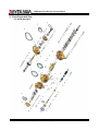
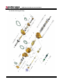
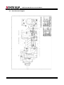
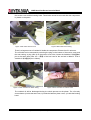
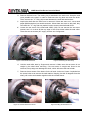
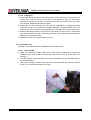
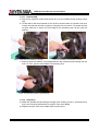
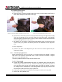
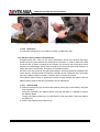
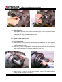
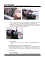
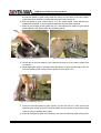
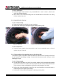
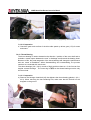
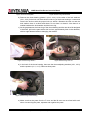
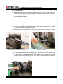
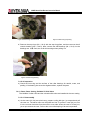
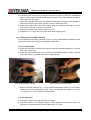
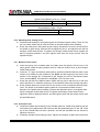
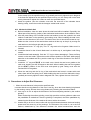
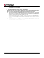
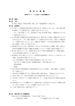
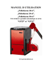
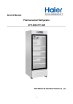
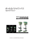
160GR Natural Gas Booster Instruction Manual
160 GR
Natural Gas Booster
Disassembly and Re-Assembly Instruction Manual
This manual is to provide instructions how to disassemble and re-assemble the 160GR machine.
Mayekawa all rights reserved. Subject to change without notice. Lat revised in October 2007
p.1
160GR Natural Gas Booster Instruction Manual
Contents
1. Introduction ..........................................................................................................................................4
2. Capacity Control Procedures ...............................................................................................................4
3. Variable Vi Structure ............................................................................................................................4
3.1.1 When the position of the current port is known ......................................................................5
3.1.2 When the Current Port is not known ....................................................................................10
4. Parts Expanded View ........................................................................................................................13
4-1
160GR Standard .................................................................................................................13
4-2
160GR with Integral Pump ..................................................................................................14
4-3
Parts Structure Diagram ......................................................................................................15
5. Parts List............................................................................................................................................17
6. Outer Dimension................................................................................................................................19
7. Disassembly ......................................................................................................................................20
Removing the Compressor ..............................................................................................................20
7.1
Interior Gas Recovery ....................................................................................................20
7.2
Removing the connecting parts ......................................................................................20
7.3
Suspending and Transferring the Compressor ...............................................................20
7.4.1
Mechanical Shaft Seal....................................................................................................22
7.4.2
Unloader Cover ..............................................................................................................24
7.4.3
Unloader Thrust Bearing ................................................................................................25
7.4.4
Balance Piston Cover .....................................................................................................27
7.4.5
Unloader Spring Retainer ...............................................................................................27
7.4.6
Balance Piston, Balance Piston Sleeve..........................................................................28
7.4.7
Speed up Gear Casing Cover ........................................................................................29
7.4.8
Speed up gear casing ....................................................................................................30
7.4.9
Disassembly of speed up gear parts on the driving side ................................................31
7.4.10
Spindle Roller Bearing....................................................................................................33
7.4.11
Disassembly of the speed up gear on the driven side ....................................................33
7.4.12
Thrust Bearing ................................................................................................................34
7.4.12
Suction Cover .................................................................................................................36
7.4.13
Rotor, Rotor Casing, Variable Vi Slide Valve ..................................................................37
7.4.14
Bearing Head and Main Bearing ....................................................................................39
8. Re-assembly......................................................................................................................................40
8.1
Bearing Head and Main Bearing .........................................................................................40
8.2
Rotor Casing, Unloader Slide Valve, Variable Vi Slide Valve, Bearing Head .......................40
8.3
Rotor Casing, Rotor ............................................................................................................41
8.4
Suction Cover......................................................................................................................41
8.5
Thrust Bearings ...................................................................................................................41
8.5
Installation of the driven side speed up gear .......................................................................42
8.6
Spindle Roller Bearings .......................................................................................................43
8.7
Building the Driving Side speed up Gear ............................................................................43
8.8
Installation of speed up Gear Casing ..................................................................................43
Mayekawa all rights reserved. Subject to change without notice. Lat revised in October 2007
p.2
160GR Natural Gas Booster Instruction Manual
8.9
Installation of speed up Spindle ..........................................................................................43
8.10 Speed up Gear Casing Cover .............................................................................................44
8.11
Balance Piston Cover ..........................................................................................................44
8.12 Unloader Cover ...................................................................................................................44
8.13 Mechanical Shaft Seal ........................................................................................................45
9. Procedures to Adjust End Clearance .................................................................................................45
Mayekawa all rights reserved. Subject to change without notice. Lat revised in October 2007
p.3
160GR Natural Gas Booster Instruction Manual
1. Introduction
The 160GR is a compressor engineered for the natural gas booster. Provided that it will be
operated by an engine, the compressor itself has an internal speed up gear that allows
different ratios according to the required air volume.
Also, the Vi on the outlet port can be changed in 4 steps with the manual capacity control as
the standard.
2. Capacity Control Procedures
On the standard 160GR specification, the capacity control is done manually by a handle.
Turning the handle in clockwise is for loading, and turning it in counter-clockwise is for
unloading.
The slide valve for the capacity control is fully loading when it is in contact with the surface of
the variable Vi slide valve. The position of Unload is determined by the stopper equipped on
the surface of the under slide rod.
Therefore, the position of full-load of the slide valve depends on the selected Vi; therefore,
the strokes of the slide valve vary as well. The strokes of the slide valve for each Vi setting
are described below.
[CAUTIONS]
・ Although there are stopper structures on the full-load position and the minimum load
position, do not turn the handle with unnecessary force when attempting capacity control.
・ When loading, turning the handle with a relatively little force can easily move the slide valve.
When the slide valve is in contact with t
・ the variable Vi slide valve for full-load, the handle becomes heavy. Then, forcing the handle
to turn may lead to the internal damage.
・
Garph2.1 Strokes for Slide Valve for Each Vi
The number of rotation
Vi Setting
Unload ⇒ Full-Load
2.3
29‐1/2
2.63
26
3.65
21
5.0
17-1/3
3. Variable Vi Structure
To change the Vi on the outlet port, the size of the radial outlet port needs to be changed by
moving the variable Vi supplementary slide valve on the full-load.
The variable Vi supplementary slide valve is fixed to the case by fix pins through pin holes on
the Variable Vi slide valve. The pin holes are located to accommodate the 4 different Vi
settings so that the Vi can be changed step-by-step.
On 160GR, the fix pins of the Variable Vi slide valve are attached from the outside of the case.
When the pins are removed, the interior gas will be discharged to the air. When changing Vi
Mayekawa all rights reserved. Subject to change without notice. Lat revised in October 2007
p.4
160GR Natural Gas Booster Instruction Manual
settings, make sure that the compressor is at a stop and that the gas inside the compressor is
discharged in the air.
Vi should not be changed while the compressor is running.
To Change Vi Settings
[CAUTIONS]
・ On this compressor, Vi should be changed after the compressor is opened to the
atmosphere.
・ Vi settings should be changed while the compressor is stopped. Also, make sure the drive is
not moving or will not move.
・ The interior air pressure of the compressor needs to be equal to the air pressure before
proceeding with changing Vi settings.
Figure1: Variable Vi Structure Cut-up View
The compressor is set at the M port when shipped. Choose the most appropriate Vi setting
for the expected operating conditions.
When the appropriate port is to be other than the M port, the Vi setting needs to be changed
before operations. When the pressure conditions dramatically change during an operation,
the Vi needs to be changed to an appropriate setting.
There are 4 ports: H (Vi=5.0), M (Vi=3.65), L (Vi=2.63), K (Vi=2.3).
3.1.1
When the position of the current port is known
When the position of the current port is known, change the Vi setting by referring to
[Graph1] and choosing the appropriate number of rotations and the direction of the rotation.
a)
Make sure the slide valve is on full-load on the current Vi condition (Turn the capacity
control handle in clockwise until it stops).
Mayekawa all rights reserved. Subject to change without notice. Lat revised in October 2007
p.5
160GR Natural Gas Booster Instruction Manual
b)
c)
d)
e)
f)
g)
Remove the guide pin from the case. When the current port is “K” or “L,” the guide pin is
located in the bottom area of the suction cover. When the current port is “M” or “K”, they
are located on the bottom of the rotor casing.
Turn the handle as many times as required to change to the desired Vi. When changing
to a higher Vi, turn the handle to the left. When changing to a lower Vi, turn the handle to
the left. For the number of rotations, refer to the Graph 2.1. Variable Vi valve can be
moved by turning the handle softly.
When changing the ports from the “K / L “ ports to the “M / H” ports, or vice versa, the plug
needs to be removed from the case and replaced with the Variable Vi valve fixing bolts.
On the “K” and “L” ports, the Variable Vi support guide pin should be attached to the
bottom of the suction cover. The plug should be attached to the bottom of the rotor
casing.
On the “M” and “H” ports, contrarily, the Variable Vi support guide pin should be attached
to the bottom of the rotor casing. The plug should be attached to the bottom of the suction
cover.
After moving the variable Vi slide valve, put the Vi guide pin into the case and lock them
with the hexagon socket head cap screws. With the Variable Vi support guide pin, use the
dice studs for the seal.
When the Vi guide pin feels heavy or caught by something, it should not be forced into the
holes. When this happens, it’s most likely that the position of the holes of the variable Vi
valve and that of the variable Vi valve fixing pin are not aligned. Slightly turn the handle to
the right or the left to find the position where the pin can be inserted smoothly.
When the variable Guide pin is smoothly inserted all the way, lock them by a proper
torque. Pun the dice stud for the seal in, and lock them in a different position from the
Variable Guide pin.
[CAUTION]
Head sizes of the variable Vi fixing bolts and the plug are not the same to avoid mistakes.
Moving Distance
(mm)
Number of Rotations
of Handle
Direction of Rotations
Position of fixing pin
Moving Distance
(mm)
From the K port
K Port ⇒ L Port
K Port ⇒ M Port
21
50.5
K port ⇒ H Port
72
3-1/2
8-3/8
12
Counter-clockwise
Suction Cover
Counter-clockwise
Rotor Casing
Counter-clockwise
Rotor Casing
From the L Port
L Port ⇒ K Port
L Port ⇒ M Port
21
29.5
L Port ⇒H Port
51
Mayekawa all rights reserved. Subject to change without notice. Lat revised in October 2007
p.6
160GR Natural Gas Booster Instruction Manual
Number of Rotations
of Handle
Direction of Rotations
Position of fixing pin
Moving Distance
(mm)
Number of Rotations
of Handle
Direction of Rotations
Position of fixing pin
Moving Distance
(mm)
Number of Rotations
of Handle
Direction of Rotations
Position of fixing pin
3-1/2
4‐7/8
8-1/2
Clockwise
Suction Cover
Counter-clockwise
Rotor Casing
Counter-clockwise
Rotor Casing
From the M Port
M Port ⇒ K Port
M Port ⇒ L Port
50.5
29.5
M Port ⇒ H Port
21.5
8-3/8
4-7/8
3-5/8
Clockwise
Suction Cover
Clockwise
Suction Cover
Counter-Clockwise
Rotor Casing
From the H Port
H Port ⇒ K Port
H Port ⇒L Port
72
51
H Port ⇒ M Port
21.5
12
8-1/2
3-5/8
Clockwise
Suction Cover
Clockwise
Suction Cover
Clockwise
Rotor Casing
Mayekawa all rights reserved. Subject to change without notice. Lat revised in October 2007
p.7
160GR Natural Gas Booster Instruction Manual
・Vi Changing Procedures < From K-Port to L-Port >
① the Position of K-Port
② Remove the Variable Vi guide pin.
③ Turn the capacity control handle 3 1/2 times
in counter-clockwise, and move the
Variable Vi slide valve to the L-port position.
④ Screw the Variable Vi guide pin in. If it is
tight, turn the handle slightly in both
directions and find a loose spot.
This completes the
changing to L-Port.
procedures
Mayekawa all rights reserved. Subject to change without notice. Lat revised in October 2007
for
p.8
160GR Natural Gas Booster Instruction Manual
・Vi Changing Procedures < From L-Port to M-Port >
① The position L-Port
② Remove the Variable Vi guide pin from the
bottom of the suction cover.
③ Turn the capacity control handle 4 7/8 times
in counter-clockwise and remove the set
bolt from the bottom of the rotor casing.
Replace it with Variable Vi guide pin.
④ Screw the Variable Vi guide pin into the
bottom of the rotor casing. If it is tight, turn
the capacity control handle slightly in both
directions.
⑤ Lock the set bolt into the bottom of the
suction cover.
This completes the
changing to the M Port.
procedures
Mayekawa all rights reserved. Subject to change without notice. Lat revised in October 2007
for
p.9
160GR Natural Gas Booster Instruction Manual
3.1.2
When the Current Port is not known
When the position of the current port is not known, move the Variable Vi valve to the
position of the stopper on the loading side. Then turn the handle as many times as
required in order to change to the desired Vi and move the Variable Vi valve.
a)
Remove the Variable Vi support guide pin from the case. (The one with the larger
size of the hex head (30mm) is the guide pin.)
b) Turn the handle in clockwise until the Variable Vi valve touches the stopper.
c) According to Graph2.1, turn the capacity handle as many times as required in
counter-clockwise and move the Variable Vi support slide valve.
On the “K” and “L” ports, the Variable Vi support guide pin should be attached to the
bottom of the suction cover, and plug should be attached to the bottom of the rotor
casing.
On the “M” and “H” ports, contrarily, the Variable Vi support guide pin should be attached
to the bottom of the rotor casing, and the plug should be attached to the bottom of
the suction cover.
d) After moving the Variable Vi support slide valve, insert Vi support guide pin and lock
it with the hex bolt. Insert the dice stud for the seal into the Variable Vi support slide
valve before tightening it.
e) When the Vi guide pin feels heavy or caught by something, it should not be forced
into the holes. When this happens, it is most likely that the position of the hole of the
Variable Vi vale and that of the Variable Vi valve guide pin are not proper aligned.
Slightly turn the handle to the right or the left to find the position where the pin can
be inserted smoothly.
f) After the Variable guide pin is smoothly inserted all the way, lock it by a proper
torque. Put the dice stud for the seal in, and lock it at the position opposite to that of
the Variable guide pin.
[CAUTION]
・ If the turning handle feels heavy, do not force the handle to turn. This may result to
damage the stopper area.
・
Moving Distance
(mm)
Number of Rotations
K Port
5
L Port
26
M Port
56
H Port
77.5
13/16
4-3/8
9-3/8
12-15/16
Counter-Clockwise
Counter-Clockwise
Counter-Clockwise
Counter-Clockwise
Suction Cover
Suction Cover
Rotor Casing
Rotor Casing
of Handle
Direction of
Rotations
Position of guide pin
Mayekawa all rights reserved. Subject to change without notice. Lat revised in October 2007
p.10
160GR Natural Gas Booster Instruction Manual
Mayekawa all rights reserved. Subject to change without notice. Lat revised in October 2007
p.11
160GR Natural Gas Booster Instruction Manual
Each Port and the Position of the Variable Vi guide pin
K-Port
L-Port
M-Port
H-Port
Mayekawa all rights reserved. Subject to change without notice. Lat revised in October 2007
p.12
160GR Natural Gas Booster Instruction Manual
4. Parts Expanded View
4-1 160GR Standard
Mayekawa all rights reserved. Subject to change without notice. Lat revised in October 2007
p.13
160GR Natural Gas Booster Instruction Manual
4-2 160GR with Integral Pump
Mayekawa all rights reserved. Subject to change without notice. Lat revised in October 2007
p.14
160GR Natural Gas
G Booster Instruction Maanual
4-3
Parts Structure Diagrram
Mayekkawa all rights reserved. Sub
bject to change
e without notice
e. Lat revised in October 200
07
p.15
5
160GR Natural Gas
G Booster Instruction Maanual
Mayekkawa all rights reserved. Sub
bject to change
e without notice
e. Lat revised in October 200
07
p.16
6
160GR Natural Gas Booster Instruction Manual
5.
Parts List
No
Name
No
Name
1
MAIN ROTOR CASING
43-1
THRUST BEARING GLAND M1
2
HEXAGON SOCKET HEAD CAP SCREW
43-2
THRUST BEARING GLAND M2
3
4
ALIGNMENT PIN
43-3
43-4
THRUST BEARING GLAND F1
THRUST BEARING GLAND F2
5
SUCTION COVER
44-1
STOP RING
6
GASKET, SUCTION COVER
44-2
STOP RING
11
BEARING HEAD
45
HEXAGONAL HEAD BOLT
12
GASKET, BEARING HEAD
46
CONICAL SPRING WASHERS
14
18
SPRING PIN
HEXAGON SOCKET HEAD CAP SCREW
48
49
SEAL RETAINER
“O” RING
19
ALIGNMENT PIN
50
OIL SEAL
20
SPRING PIN
51
SEAL COVER
22
BALANCE PISTON COVER
52
GASKET, SEAL COVER
23
GASKET, BALANCE PISTON COVER
53
HEXAGON SOCKET HEAD CAP SCREW
24
25
HEXAGON SOCKET HEAD CAP SCREW
MALE ROTOR
100
SHAFT KEY
MECHANICAL SEAL ASSY.
26
FEMALE ROTOR
169
SPEED UP GEAR CASTING
27-1
MAIN BEARING M
170
GASKET, SPEED UP GEAR CASTING
27-2
MAIN BEARING F
171
SPEED UP GEAR CASTING COVER
28-1
SIDE BEARING M
172
GASKET, SPEED UP GEAR CASTING COVER
28-2
29-1
SIDE BEARING F
STOP RING
174
175
SPEED UP DRIVE GEAR
SPEED UP DRIVE GEAR KEY
29-2
STOP RING
176
SPEED UP GEAR SPACER
29-3
LABYRINTH SEAL M
179
SPEED UP DRIVEN GEAR
29-4
LABYRINTH SEAL F
180
SPEED UP DRIVEN GEAR KEY
30
BALANCE PISTON
181
SPEED UP DRIVEN GEAR SPACER
31
32
KEY, BALANCE PISTON
STOP RING
183
184
SIDE BEARING, SPEED UP GEAR
SPRING PIN
33
SLEEVE, BALANCE PISTON
185
ROLLING BEARING SPEED UP GEAR
34
SPRING PIN
186
STOP RING
35
“O” RING
187
STOP RING
38-1
THRUST BEARING M
188
SPEED UP GEAR SPINDLE
38-2
39-1
THRUST BEARING F
LOCK NUT
189
190
SPEED UP GEAR, THRUST BEARING
SPEED UP GEAR, THRUST BEARING GLAND
39-2
LOCK NUT
191
GLAND BOLT
39-3
LOCK NUT
192
SPRING WASHER
40-1
LOCK WASHER
193
LOCK NUT
40-2
40-3
LOCK WASHER
LOCK WASHER
194
195
LOCK WASHER
HEXAGON SOCKET HEAD CAP SCREW
41-1
BEARING SPACER M
196-1
OIL CONTROL THROTTLE COMP MS
Mayekawa all rights reserved. Subject to change without notice. Lat revised in October 2007
p.17
160GR Natural Gas Booster Instruction Manual
No
Name
No
Name
41-2
BEARING SPACER F
196-2
OIL CONTROL THROTTLE COMP FS
42-1
SPACER, THRUST BEARING M ALIGNMENT
196-3
OIL CONTROL THROTTLE COMP MD
42-2
196-5
SPACER, THRUST BEARING F ALIGNMENT
OIL CONTROL THROTTLE, SPEED UP GEAR
196-4
237-C
OIL CONTROL THROTTLE COMP FD
TORSIONAL SLIP WASHER C
237-A
TORSIONAL SLIP WASHER A
237-D
TORSIONAL SLIP WASHER D
237-B
TORSIONAL SLIP WASHER B
237-E
TORSIONAL SLIP WASHER E
54
UNLOADER SLIDE VALVE (1)
196-5
OIL CONTROL THROTTLE, SPEED UP GEARS
55
58
UNLOADER SLIDE VALVE (2)
HEXAGON SOCKET HEAD CAP SCREW
246
247
UNLOADER SLIDE VAVLE GUIDE
HEXAGON SOCKET HEAD CAP SCREW
67
UNLOADER PUSH ROD
248
SPRING WASHER
69
LOCK NUT
249
ALIGNMENT PIN
70
LOCK WASHER
273
HEXAGON NUT
74
UNLOADER CYLINDER COVER
280
PLAIN WASHER
75
76
GASKET, UNLOADER CYLINDER COVER
HEXAGON SOCKET HEAD CAP SCREW
289
326
VI VARIABLE SLIDE VALVE
SPRING HOLDER
79
THRUST WASHER
445
BUSH STOPPER
80
BEARING GLAND
446
SLIDING VALVE STOPPER
81
HEXAGON SOCKET HEAD CAP SCREW
452
HEXAGON SOCKET HEAD CAP SCREW
82
“O” RING
454-1
GUIDE PIN
83
84
SPRING
SPRING RETAINER
454-2
455
PLUG
HEXAGON SOCKET HEAD CAP SCREW
458
HEXAGON SOCKET HEAD CAP SCREW
523
“O” RING
Mayekawa all rights reserved. Subject to change without notice. Lat revised in October 2007
p.18
160GR Natural Gas Booster Instruction Manual
6. Outer Dimension
Mayekawa all rights reserved. Subject to change without notice. Lat revised in October 2007
p.19
160GR Natural Gas Booster Instruction Manual
7. Disassembly
Preparation
Although screw compressors are reliable machines, they need to be disassembled to have
their parts inspected after operating for a certain amount of time. In this chapter, the
procedures and instructions for disassembly and parts inspection will be provided.
Disassembling a compressor at the installed site is limited to: the shaft seal parts, the
unloader parts, and the balance piston parts. When the compressor is to be entirely
disassembled, the compressor needs to be removed from the mounting and placed in a
proper environment for disassembly.
Before the disassembly procedures, parts inspections and their handling, study this manual
and the actual compressor and understand the structure very well.
Tools for Disassembly
For disassembly process, properly use recommended tools for disassembly. The
recommended tools include special tools that need to be ordered from Mycom / Mayekawa
MFG.
As general tools, a hammer, a monkey wrench, a filer, and a sand paper (#800 and above)
will be required.
Other than the tools, you will need oil to wash the oil, new refrigeration oil, an oil can, a can
for drained oil, and waste cloth, etc. Use a large platen for the process, and choose a dry,
large environment with the least amount of dust or sand.
Removing the Compressor
7.1 Interior Gas Recovery
When the screw compressor is at a stop, the inside pressure of the compressor is very
high. Equalize the pressure with the lower pressure side. Then recover the gas to
equalize the pressure as the air pressure or a bit lower than that.
7.2 Removing the connecting parts
Make sure that the inside pressure of the compressor is the same as or a bit lower than
the air pressure before starting to remove parts.
Remove the connecting parts to the compressor, the coupling, the suction pipe, the
discharge pipe, refueling pipe, and the fixing bolt in series.
* When removing the refueling pipe (etc.), prepare a receiver for the residual oil that
overflows from the inside.
7.3 Suspending and Transferring the Compressor
The flange of the suction pipe is located on top of the compressor. Before suspending
the compressor, remove a part of it if the piping seems to interfere with the suspension.
Use the eyebolt on the bearing head and the two eyebolts on the suction cover to
suspend the compressor. When suspending, adjust the length with chain blocks etc. to
keep the compressor leveled.
In the preparation of disassembling the compressor entirely, have the compressor suspended
and remove the 4~6 hexagon socket head cap screws on the bottom of the casing which lock
Mayekawa all rights reserved. Subject to change without notice. Lat revised in October 2007
p.20
160GR Natural Gas Booster Instruction Manual
the suction cover and the bearing head. These bolts cannot be removed after the compressor
is placed on the paten.
Figure 1 Bolt under Suction Cover
Figure 2 Bolt under Rotor Casing
There is a large amount of residual oil inside the compressor. Extract the oil in advance.
The oil inside can be extracted by removing the plug on the bottom of the suction cover and
the rotor casing, or plug (454-2) on the suction cover. Also, loosen the Variable Vi 弁位置決め
pin at the same time (note: the 二面幅 of the hex head of the set bolt is 288mm. That of
Variable Vi 弁位置きめ pin is 30mm).
Figure 3 when set bolt is on Rotor casing
Figure 4 when set bolt is on Suction Cover
The residual oil will be discharged during the whole process on the platen. The oil mostly
accumulates: a) inside the seal cover, b) inside the balance piston cover, c) inside the bearing
head.
Mayekawa all rights reserved. Subject to change without notice. Lat revised in October 2007
p.21
160GR Natural Gas Booster Instruction Manual
The Order of Disassembly
Follow the order shown below to disassemble and inspect the compressor.
The order of the compressor disassembly:
1)
2)
3)
4)
5)
6)
7)
8)
9)
10)
11)
Mechanical shaft sea
Unloader cover and unloader thrust bearing
Balance piston cover
Balance piston
Speed up gear casing cover
Speed up gear casing
Thrust bearing
Suction cover and side bearing
Rotors
Variable Vi slide valve, unloader slide valve
Bearing head, main bearing
7.4.1 Mechanical Shaft Seal
7.4.1.1 Disassembly
This compressor uses a Balance-type single seal for the mechanical seal. Carbon and
special cast iron are used for the sliding surface. The moving part is sealed with bellows,
and an “O” ring is used for the packing gland.
a) Remove 4 out of the 6 bolts with the hex head (53) on the seal cover (51), leaving 2
bolts in a symmetry position. Then, loosen the 2 remained bolts alternately. The
spring force of the shaft seal (100) will push the seal cover up, which will create a gap
between the seal cover and the gear cover.
During this process, receive the residual oil that will flow from this gap. If the gasket is
stuck, move the seal cover to peel it when the seal cover gets loosened a little.
Figure 5 Seal Cover
Mayekawa all rights reserved. Subject to change without notice. Lat revised in October 2007
p.22
160GR Natural Gas Booster Instruction Manual
b) Remove the seal cover. The mating ring is attached to the seal cover. Keep the seal
cover parallel to the shaft, in order to make sure the ring does not touch the shaft.
Then, remove the “O” Ring (49) located between the seal and seal retainer.
c) Inspect the shaft after the seal cover is removed. If there are scars on it, use a sand
paper (#800 and above) to sand them down. When there are scars on the shaft, they
can catch the “O” ring and may make it hard to remove the shaft seal ASSY.
d) Loosen the set screw of the shaft seal ASSY (100). Do not remove the set screw.
Instead, turn it 3~4 times till the top edge of the screw hides inside the seal collar.
There are two set screws (90° angle), that are out of alignment.
Figure 6 Seal Collar Set Screw
Figure 7 Removing the Seal body
e) Hold the seal collar area by fingers and remove it. Make sure the set screw is not
caught by the shaft when removing. If the set screw is caught and forced to be
removed, its top edge can damage the shaft, which will cause the seal to leak.
f) Remove the set screw of the sleeve for the oil seal. As the tool, insert 2 eyebolts into
the screw holes as to remove the seal retainer. Keeping it at the 90 degrees from the
shaft, pull out the seal retainer together with the oil seal sleeve.
Figure 8 Oil Seal Sleeve Set Screw
Figure 9 Pulling Seal Retainer Out
Mayekawa all rights reserved. Subject to change without notice. Lat revised in October 2007
p.23
160GR Natural Gas Booster Instruction Manual
7.4.1.2 Inspection
a) Inspect the sliding surfaces of the mating ring and the seal ring. If the surfaces are
evenly worn, and the amount of the wear is not significant, they can be reused.
However, if the wear is not even, or if there is a peel on the surfaces, they can cause
the seal leak. Replace them with new parts.
b) Inspect the “O” ring. Basically, the “O” rings are expected to be replaced at every
inspection, for the “O” rings tend to be swollen, distorted, or hardened easily. The 3 “O”
rings used on the seal are for the seal retainer, for the seal ASSY, and for mating ring.
c) Examine the sliding surface of the oil seal of the sleeve for the oil seal. If it has been
worn down, replace both the oil seal and the sleeve. The oil seal is a special product.
Replace it with a genuine part.
d) Replace the seal cover gasket with a new one.
7.4.2 Unloader Cover
The seal for the under slide rod is installed in the unloader cover.
7.4.2.1 Disassembly
a) Place the Variable Vi support slide valve at the full-load position and remove the
Variable Vi plug (454-1) that is screwed onto the suction cover (5) or the main rotor
casing (1).
b) Turn the capacity control handle in the counter-clockwise to move the slide valve to
the unload position.
c) Pull out the hexagon socket head cap screw (24) that holds the unloader cylinder
cover (74) on the balance piston cover (22).
Mayekawa all rights reserved. Subject to change without notice. Lat revised in October 2007
p.24
160GR Natural Gas Booster Instruction Manual
Figure 10 Removing Unloader cover bolt
Figure 11 Removing Variable Vi Support pin
(with Suction Cover on)
d) The “O” ring (82) to seal the unloader push rod (67) is installed on the unloader cover.
When pulling the unloader cover out, keep the hole of the cover parallel to the
unloader slide rod. Forcing the angled cover to be pulled out can damage the shaft.
Use a receiver for the residual oil that may flow from the gap in the cover flange in this
process.
Figure 12 Removing Unload Cover
7.4.2.2 Inspection
a) Check of there is a wear in the seal area of the unloader slide rod.
b) Inspect the “O” ring (82). Inspect the “O” ring. Basically, the “O” rings are expected to
be replaced at every inspection, for the “O” rings tend to be swollen, distorted, or
hardened easily, and such conditions will cause a leak.
7.4.3 Unloader Thrust Bearing
The Unloader thrust bearing is the bearing that decides the position of the unloader slide
rod and receives the thrust load that is created on the slide valve from unloading.
Mayekawa all rights reserved. Subject to change without notice. Lat revised in October 2007
p.25
160GR Natural Gas Booster Instruction Manual
7.4.3.1 Disassembly
a) Pull out the hexagon socket head screw (81) on the unloader thrust bearing cramp
(80).
b) Lift the tabs of the thrust washer for the lock nut that are bent to hold the inner race
Loosen and remove the lock nut (69) by using the lock nut wrench. To loosen the lock
nut (69), hold the ◇ area in the front edge of the unloader push rod (67) with the
spanner.
Figure 13 Unloader Trust Bearing Cram bolt
Figure 14 Unloader Thrust Bearing Lock nut
c) Remove the thrust washer (79) located between the unloader thrust bearing and the
lock nut. Then, pull out the unloader TAC bearing (273).
Figure 15 Removing Unloader Thrust Bearing
7.4.3.2 Inspection
a) Wash the unloader thrust bearing thoroughly with washing oil (etc.), and blow the oil
by the air. Check the ball surface for tarnish, scars, and flaking.
b) Replace the part, when even a little defect can be found.
Mayekawa all rights reserved. Subject to change without notice. Lat revised in October 2007
p.26
160GR Natural Gas Booster Instruction Manual
7.4.4 Balance Piston Cover
7.4.4.1 Disassembly
a) Remove the top 2 hexagon socket head screws (24), and insert safety bolts. Remove
all the other hexagon socket head screws (24).
Figure 16 Removing Bolts on Balance Piston Cover
Figure 17 Removing Balance Piston Cover
b) The position of the balance piston cover (22) is determined by the alignment pin (596).
There are 2 openings for the eye bolts. Insert the eye bolts evenly, and gradually
create an opening with the suction cover (5). Use a receiver to catch the oil that flows
from the opening with the suction cover.
c) As drawing the eye bolts in while keeping the balance piston cover (22) and the
suction cover (5) in parallel, the balance piston will be detached from the alignment
pins.
7.4.4.2 Inspection
a) Check for any bent on the alignment pins. When a bent is found, replace the part.
Replace the gasket.
7.4.5 Unloader Spring Retainer
When transferring from a low Vi to a high Vi, the spring pushes the Variable Vi support
slide valve to the capacity control slide valve in order to move the Variable Vi support
slide valve to the discharge side.
The spring retainer holds the spring with the suction cover.
7.4.5.1 Disassembly
a) Loosen the hexagon socket head screws (452) in a symmetry, which fixes the spring
retainer (84) on the suction cover (5). As there is the spring (83) inside, make sure to
move the slide valve is at the unload position after removing the Variable Vi support
pin. Failing to do so is dangerous, as the spring retainer (84) may jump out when the
last hexagon socket head screw (452) is pulled out.
b) Holding the spring retainer (84), pull out the hexagon socket head screw (452).
c) Pull out the spring retainer (84).
Mayekawa all rights reserved. Subject to change without notice. Lat revised in October 2007
p.27
160GR Natural Gas Booster Instruction Manual
Figure 18 Hexagon socket head screw
Figure 19 Removing Spring Retainer
7.4.5.2 Inspection
a) Check the spring (83) for any defects. If there is, replace the part.
7.4.6 Balance Piston, Balance Piston Sleeve
Compared with the F rotor, on the screw compressor, the M rotor receives the larger
thrust load by the gas load from the discharge to the suction. In order to reduce the load
on the M rotor, a piston is located on the suction end of the M rotor which puts the oil
pressure to the discharge side in order to balance out the thrust load, which results in a
longer life span of the bearing. This piston is the balance piston.
On the F rotor side, however, the gas load towards in the thrust direction is smaller than
on the M rotor, and the number of rotations is smaller as well. Therefore, the F rotor does
not need a balance piston to assure a long life span of the thrust bearing.
The balance piston sleeve is structured to keep the gap between the sleeve and the
balance piston small so that the oil pressure can be maintained.
7.4.6.1 Disassembly
a) Remove the stop ring (32) that fixes the balance piston (30) on the shaft by using the
stop ring pliers.
Screw the eyebolts in the balance piston (30) and pull them in a parallel to remove
the balance piston.
Though the balance piston key (31) will remain on the rotor shaft, it does not need to
be pulled out.
b) Pull out the balance piston sleeve (33).
Mayekawa all rights reserved. Subject to change without notice. Lat revised in October 2007
p.28
160GR Natural Gas Booster Instruction Manual
Figure 20 Stop Ring on Balance Piston
Figure 21 Removing Balance Piston Sleeve
7.4.6.2 Inspection
Although there might be some wear on the balance piston, there is no problem unless
the wear is significant.
Replace the “O” ring of the balance piston sleeve.
7.4.7 Speed up Gear Casing Cover
7.4.7.1 Disassembly
a) Remove the top 2 hexagon socket head screws (195) that tighten the speed up gear
casing cover (171). Insert the safety bolts. Then, remove all the other hexagon
socket head screws (195).
b) Insert the eye bolts evenly into the 2 screw holes (brand new holes are sealed with
caps) for the eye bolts on the speed up gear casing cover (171).
Figure 22 Attaching Safety Bolts
Figure 23 Removing Alignment pins
c) Use a receiver to catch the oil that flows from the opening of the speed up gear
casing (169), as inserting the eye bolts.
Mayekawa all rights reserved. Subject to change without notice. Lat revised in October 2007
p.29
160GR Natural Gas Booster Instruction Manual
d) Also, as inserting the eye bolts so that the speed up gear casing cover (171) and the
speed up gear casing (169) are in a parallel, the speed up gear casing cover will be
detached from the set alignment pins (19).
e) Screw the suspension bolts into the speed up gear casing cover. With this bolts
suspended, remove the speed up gear casing cover.
Figure 24 Removing Gear Cover
7.4.7.2 Inspection
Check for a bent on the alignment pins. Replace any defected parts. Replace the
gasket.
7.4.8 Speed up gear casing
The speed up gear spindle with the speed up gear is fixed by the thrust bearing on the
speed up gear casing. Separate the speed up gear casing with the speed up gear and
the speed up gear spindle from the bearing head.
7.4.8.1 Disassembly
a) Screw the eyebolts in the screwed hole of the speed up gear side bearing (183), and
pull them out.
b) Remove the top 2 hexagon socket head screws that tighten the speed up gear casing
(169). Then insert the safety bolts in the same places. Remove all the other bolts.
Mayekawa all rights reserved. Subject to change without notice. Lat revised in October 2007
p.30
160GR Natural Gas Booster Instruction Manual
Figure 25 Removing Support Metal
Figure 26 Attaching Safety Bolts
c) Insert the removed bolts into the screwed hole of the speed up gear casing (169)
evenly. The speed up gear casing will be detached from the set alignment pins.
d) Suspend the speed up gear casing (169) by the eyebolts and keep it in a parallel with
the shaft. When removing, keep the speed up drive gear (174) and the speed up gear
spindle (188) attached with the speed up gear casing.
Figure 27 Removing Gear Casing
7.4.8.2 Inspection
Check for a bent on the alignment pin. Replace any defected parts. Replace the
gasket.
7.4.9 Disassembly of speed up gear parts on the driving side
When exchanging the speed up gear or the radial bearing for the speed up gear spindle,
disassemble the whole speed up gear parts. When exchanging the thrust bearing of the
speed up gear spindle, the speed up gear does not need to be detached from the speed
up gear spindle.
7.4.9.1 Disassembly
a) When removing the speed up gear spindle (188), fix the speed up gear casing (169)
Mayekawa all rights reserved. Subject to change without notice. Lat revised in October 2007
p.31
160GR Natural Gas Booster Instruction Manual
so that the speed up gear comes atop the casing. Lift the tabs of the lock washer
(270) and loosen the lock nut (269) with the proper lock nut wrench.
b) Flip the speed up gear casing and fix it on the platen again. Place blocks (etc.)
underneath the platen to avoid collisions between the part and the ground.
c) Remove the hexagon socket gland bolt (191) that tightens the speed up gear thrust
bearing gland (190). Remove the thrust bearing gland.
Figure 28 Speed up Gear Lock nut
Figure 29 Speed Up Gear Thrust Bearing Gland
d) Lift the tabs on the lock washer (194). Remove the lock nut (193) with the proper lock
nut wrench.
e) While tapping the edge of the shaft of the gear speed up gear spindle (188), pull it out
from the speed up gear casing with the speed up drive gear (174).
Figure 30 Thrust Bearing Lock nut
f) From the removed speed up gear spindle, pull out the lock nut. Then remove the
speed up gear speed up gear on the driving side from the speed up gear side bearing
(183) by using something like a pulley.
g) Remove the speed up gear thrust bearing (189) from the speed up gear casing (169).
Mayekawa all rights reserved. Subject to change without notice. Lat revised in October 2007
p.32
160GR Natural Gas Booster Instruction Manual
7.4.9.2 Inspection
a) Check the gear tooth surface for any remarkable hit or wear. If there is, look for the
cause and replace the part.
b) When there is an unusual running trace or unusual wear on the ball or the rolling
surface, replace the part.
7.4.10 Spindle Roller Bearing
7.4.10.1 Disassembly
a) Remove the stop ring (186) by the stop ring pliers.
b) Pull out the outer-ring of the speed up gear rolling bearing (185).
Figure 31 Stop Ring
Figure 32 Removing Outer-Ring of Rolling Bearing
7.4.10.2 Inspection
a) Check the roller bearing inner-ring and the コロ for any remarkable wear or hit and
replace the part if there is.
7.4.11 Disassembly of the speed up gear on the driven side
The speed up gear on the driven side is located at the M rotor side. The edge of the shaft
is the journal of the sliding bearing. Proceed with the process after curing to avoid
damaging the part.
7.4.11.1 Disassembly
a) Lift the tabs of the lock nut (39-3) for the lock washer (40-3) that holds the passive
gear. Remove the lock nut (39-3) with the proper lock nut wrench. Make sure that the
lock nut wrench does not damage the journal area of the edge of the shaft.
b) Pull out the driven side speed up gear from the rotor. Make sure to use both hands to
hold the gear, as the gear is quite heavy.
c) At last, pull out the passive side speed up driven gear key (180).
Mayekawa all rights reserved. Subject to change without notice. Lat revised in October 2007
p.33
160GR Natural Gas Booster Instruction Manual
Figure 33 Removing Lock nut
Figure 34 Removing Speed Up Driven Gear
7.4.11.2 Inspection
a) Check the gear tooth surface of the drive side speed up driven gear (179) for scars
and wears.
7.4.12 Thrust Bearing
The thrust bearing is used to determine the direction / position of the rotor shaft and to
maintain a certain space between the rotor’s discharge end face and the bearing head.
Because of this, the parts integration of the thrust bearings will change the performance
and can cause a breakdown. When disassembling and re-assembling, the process
needs to be conducted with much care.
The thrust bearings (38-1, 38-2) consist of high precision class etc. of the front-to-front
angular contact bearings. The outer-ring is 隙間 so that these bearings receive only
the thrust load.
7.4.11.1 Inspection
a) Remove the hexagon head bolt (45) that tightens the thrust bearing glands 1 (43-1,
43-3). When removing the last remaining bolt, make sure that the bolt will not be
dropped on the ground.
Mayekawa all rights reserved. Subject to change without notice. Lat revised in October 2007
p.34
160GR Natural Gas Booster Instruction Manual
Figure 35 Thrust Cramp Bolt
Figure 36 Removing Thrust Gland
b) Remove the thrust bearing glands 2 (43-2, 43-4). Lift the tabs of the lock washers
(39-1, 39-2) for the lock nut that hold the inner-ring of the thrust bearings. Loosen and
remove the lock nut with the proper lock nut wrench. Between the lock nut and the
lock washer, there is a think steel sheet. Do not lose it or bend it. Also there is a
washer between the lock washer and the inner-ring.
c) As the gap between the inner-ring of the thrust bearing and the rotor shaft is designed
to be loose, pull out the parts with a thin iron bar, approximately 3mm in the diameter,
with its edge flattened without damaging the retainer.
Figure 37 Removing Gland 2
Figure 38 Removing Lock nut
d) In the back of the thrust bearing, there are the thrust adjusting washers (42-1, 42-2)
and the spacers (41-1, 41-2). Remove these parts.
Figure 39 Removing Thrust Bearing
e) Make sure that the parts from the F rotor and the M rotor are not mixed with each
other. As removing the parts, separate and organize the parts.
Mayekawa all rights reserved. Subject to change without notice. Lat revised in October 2007
p.35
160GR Natural Gas Booster Instruction Manual
7.4.11.2 Inspection
a) Wash the thrust bearing thoroughly with washing oil. Check the ball surface for
tarnish, scars, peeling, flaking, and distortion. Then check the retainer for wears and
distortions. Finally check the inner-ring and the running trace of the outer-ring for
scars, peeling, and flaking.
b) When there is even a slightest defect on the thrust bearings, replace the parts.
7.4.12 Suction Cover
7.4.12.1 Disassembly
a) Loosen the hexagon socket head cap screw (2) that attach the suction cover (5) with
the main rotor casing (1) and remove them.
b) Insert the removed screws into the screw holes for eye bolts on the suction cover and
push the rotor casing (1) evenly. Insert them slowly, alternating left and right in turns.
Figure 40 Removing Suction Cover Bolts
Figure 41 Push Bolt
c) On the platen, after removing the alignment pin, separate the suction cover (5) from
the rotor casing (1), keeping the suction cover parallel to the rotor shaft. If the suction
cover (5) cannot be pulled out, lift the rotor casing (1) side slightly as pulling the
suction cover (5).
Mayekawa all rights reserved. Subject to change without notice. Lat revised in October 2007
p.36
160GR Natural Gas Booster Instruction Manual
Figure 42 Removing Suction Cover
Figure 43 Removing Stop Ring
d) Remove the stop rings (29-1, 29-2) with the stop ring pliers, and then remove the oil
control throttles (196-1, 196-2). Next, remove the side bearings (28-1, 28-2). As the
bearings are 中間 fitted, do not tilt the bearings when pulling out.
Figure 44 Removing Bearing
7.4.12.2 Inspection
a) Check the inner-ring and the surface of the roller bearings for tarnish, scars, and
peeling. If the bearing has even the slightest defect, replace the parts.
7.4.13 Rotor, Rotor Casing, Variable Vi Slide Valve
The Variable Vi slide valve and the unloader slide valve are installed in the rotor casing.
7.4.13.1 Disassembly
a) As the rotors (25, 26) are quite heavy, prepare a sling belt (etc.) to suspend and pull
the rotor out. The either rotors can be pulled out first. To pull the F rotor (26) out, turn
it in the counter-clockwise from the suction cover side. When the rotor is 2/3 way out,
put a rope around the rotor. Pull out the rotor while keeping it flat and suspended.
Mayekawa all rights reserved. Subject to change without notice. Lat revised in October 2007
p.37
160GR Natural Gas Booster Instruction Manual
b) Use V Blocks (etc.) to support the shaft of the removed rotor. Do not place the rotor
directly on the floor and damage the outer rim.
c) Follow the same procedures to remove the other rotor. When pulling the rotor out,
balance it well so that the rotor shaft will not be damaged.
Figure 45 Rotor Casing
Figure 46 Removing Rotor
d) As the Variable Vi valve set pin has been already removed, the Variable Vi valve can
be drawn out by pulling the unloader slide rod. Remove the Variable Vi valve. Then,
when the unloader slide rod is pulled again, this time the slide valve itself will be
drawn out. Remove the slide valve.
Figure 47 Removing Variable Vi support Slide Valve
Figure 48 Removing Slide Valve & Slide Rod
e) Turn the unloader push rod (67) in counter-clockwise and remove it from the slide
valves (54, 55). Pull out the hexagon socket head screw (455) that fixes the slide
valve bush stopper (445) with the slide valve (54). Remove the slide valve bush
stopper (445).
7.4.13.2 Inspection
a) Check the journal area of the rotors for wears.
Mayekawa all rights reserved. Subject to change without notice. Lat revised in October 2007
p.38
160GR Natural Gas Booster Instruction Manual
b) Check the rotor tooth for the hit and the outer rim for wears. If there is a remarkable
wear, it could be that a foreign substance has entered. The suction strainer and the oil
filter need to be examined.
c) Inspect the unloader slide valve, the sliding surfaces and the space of the Variable Vi
slide valve and the rotor casing. If there is a wear, replace the parts.
d) Inspect the inside of the rotor casing. When there is no defect on the outer rim of the
rotor, there should be no defect in the inside.
e) Check the screws of the unloader slide valve rod.
f) Replace the “O” ring (523) of the slide valve bush stopper (445).
7.4.14 Bearing Head and Main Bearing
If the compressor has been operating for over 2 years, disassemble the bearing head
(11) and the main rotor casing (1) and replace the gaskets.
7.4.14.1 Disassemble
a) Remove the hexagon socket head screw that attaches the bearing head (11) with the
main rotor casing (10).
b) Insert the removed bolts into 2 screw holes on the bearing head (11) side. Push the
main rotor casing (1) equally. Remove the alignment pin.
Figure 49 Removing Main Bearing
Figure 50 Removing Labyrinth Seal
c) Remove the main bearings (27-1, 27-2) located at the bearing head (11). In the back,
there are the oil control throttles (196-3, 196-4), the labyrinth seals (29-3, 29-4), and
“O” rings (433-1, 433-2). Remove all these parts.
7.4.14.2 Inspection
a) Check the surface of the main bearing for defects.
b) Check the interior of the labyrinth seal for wears. Replace the part when there is a
large scar or a large amount of wear. Replace the “O” rings.
Mayekawa all rights reserved. Subject to change without notice. Lat revised in October 2007
p.39
160GR Natural Gas Booster Instruction Manual
8. Re-assembly
When the inspections and repair of each part has been completed, proceed to the process of
re-assembling the compressor. Reassembling process is essentially carried out in reverse
order of disassembly. Use the same tools used for disassembly and pay attentions for safety.
The tools to be used should be thoroughly cleaned. The parts to be assembled should be
washed and lubricated before assembled.
8.1
Bearing Head and Main Bearing
a) Before installing the main bearing, the labyrinth seals and the lubrication rings need to
be installed.
b) First, install the labyrinth seals. Do not forget “O” rings will be inserted in the outer rim. If
the labyrinth seals and the “O” rings cannot be installed together, install the “O” rings in
the bearing head first and then the labyrinth seals. Make sure the labyrinth seals are
inserted all the way to the back. If the seals cannot be inserted all the way, they may be
chewing the “O” rings.
c) Then, install the lubrication rings. The labyrinth seals, which should be installed in the
prior step, have the stopper pin. Install the lubrication rings to match the pin holes on the
seals.
d) The main bearing is fitted in the gap. If the bearings are inserted straight to the housing,
they should be inserted quite smoothly. When the bearings do not go in smoothly, they
are not straight to the housing. Use a pad, and tap them to straighten them.
e) Apply some oil to the gasket that is to be installed between the bearing head and the
rotor casing. The gasket is not symmetric. Make sure to attach it in the right direction.
8.2
Rotor Casing, Unloader Slide Valve, Variable Vi Slide Valve, Bearing Head
a) Unloader Slide Valve
Attach the “O” ring (523) to the slide valve end plate. Install the end plate to the slide
valve. Install the unloader slide rod in the unload slide valve by screwing it all the way in
clockwise.
b) Rotor Casing
Clean oil line, and do not forget to plug them. Install the unloader slide valve in the rotor
casing. Check the movement in the shaft direction. Likewise, check the movement of the
Variable Vi slide valve.
c) Install the rotor casing the bearing head. Hammer the alignment pins in, and insert the
hexagon socket head screws. To tighten the hexagon socket head screws, evenly
tighten the bolts in diagonal. Use a torque wrench to tighten with a proper torque in the
end. A few bolts on the bottom are to be tightened later.
d) Install the unloader slide valve and the unloader slide rod, which are already put together,
in the rotor casing. Attach the Variable Vi slide valve.
e) If the bearing head gasket hangs out to the interior of the rotor casing, cut the gasket off
with a knife (etc.). When the gasket is left there, it can be caught between the edge of the
rotor and the bearing head, which prevents the proper thrust adjustment.
Mayekawa all rights reserved. Subject to change without notice. Lat revised in October 2007
p.40
160GR Natural Gas Booster Instruction Manual
8.3
Rotor Casing, Rotor
a) When replacing the main bearings and the side bearings, put shrink fit on the inner-ring
with the rotor.
b) Apply oil on the bearing outer-ring inserted in the bearing head and the bearing
inner-ring attached to the rotor. Install the M rotor into the rotor casing first. With the use
of chain blocks (etc.), suspend and the balance the rotor with a nylon sling. When the
rotor is half-way in the casing, remove the suspension and push it in.
c) On the teeth tip of the F rotor suction side, there number ①, ② are stamped. Turn the
rotor so that these stamps face the M rotor side.
d) Suspend the F rotor. Place the M rotor so that the tooth that has the ① stamped faces
the F rotor side.
e) Place the tooth with the ① stamp of the M rotor between the ①, ② teeth of the F rotor,
and insert the F rotor half-way. Then remove the nylon sling. Push the rotor all the way
in.
8.4
Suction Cover
a) Install the side bearings. Like the main bearings, the side bearings are すき間 fitted. Do
not tilt them. When it is difficult to install the side bearings as it is tilted, put a pad and tap
it to straighten it.
b) Place the lubricating ring in the way where the nozzle faces the bearing, and hold it with
the stop ring. Make sure the oil discharge holes are vertically aligned.
c) Push the unloader slide rod towards the unload position, and expose the half of the
unloader slide rod from the rotor casing.
d) Match the unloader slide rod and the hole on the suction cover. Slide the suction cover
on the platen close to the rotor casing.
e) Match the positions of the side bearing and the rotor shaft, and put them together by
pushing them in parallel to the shaft.
f) Hammer the set alignment pins in, and tighten the hexagon socket head screws. To
tighten the hexagon socket head screws, evenly tighten the bolts in diagonal. Use a
torque wrench to tighten with a proper torque in the end.
g) Move the unloader slide rod to the direction of the shaft to check the movement of the
unloader slide valve and the Variable Vi slide valve. Then softly turn the M rotor by hand
to make sure that the rotor turns.
8.5
Thrust Bearings
a) If the disassembled thrust bearing is to be installed as disassembled, install it in the
same direction as that of the thrust adjusting washer and the spacer of the M/F rotors
when they were removed. Special care is required so that the journal area of the tip of
the M rotor will not be damaged.
b) When the washer or the thrust adjusting washer has foreign objects in them, the
measurement of the same thrust bearings can change. The inaccuracy in the
measurement will prevent the adjustment of the end clearance. Make sure to keep any
foreign objects away from the parts.
Mayekawa all rights reserved. Subject to change without notice. Lat revised in October 2007
p.41
160GR Natural Gas Booster Instruction Manual
c) First, install the washer and the thrust adjusting washer, and proceed to the thrust
bearings. Install the thrust bearings in the way that the tip of the “V” mark faces the rotor
side. When the thrust bearings are facing the wrong way, the measurement of the
outer-ring and the inner-ring change. The inaccuracy in the measurement will change
the end clearance from the value before the disassembly.
d) Install the thrust washer and the lock washer. Insert the packing (はさみ板), and fix the
inner-ring of the thrust bearing with the rotor shaft by the lock nut. If the thrust bearing
has been replaced, tighten the lock nut slowly to make sure there is an end clearance.
With a brand-new bearing, there may be a little difference in the measurements of the
outer-ring and the inner-ring which will cancel the end clearance. Tightening the nuts on
the new bearing will push the ball towards the moving part and will leave pressure traces.
When there is no end clearance, replace the thrust adjusting washer with one whose
width is thicker, or insert a shim to adjust the measurement.
e) Tighten the lock nuts with the torque specified below. Match the position of the groove on
the lock nut and that of the tabs on the lock washer.
f) With the inner-ring of the thrust bearing attached with the rotor shaft, push the tip of the
rotor’s discharge side towards the discharge side. Push it to the position where there is
no end clearance (0).
g) With the rotor moved to the discharge side, place the tip of the dial indicator on the top of
the rotor suction, and set the needle at “0.” Install the thrust cramp-2. Get ready to install
the thrust cramp-1.
h) With bolts, tightens the bearing cramps evenly with the torque specified below. This
process will create an opening in the top of the rotor discharge side, as the thrust
bearings are pushed by the bearing cramps.
i) Read the value on the dial indicator at this time. This value indicates the moving distance
of the rotor and also the end clearance. When the end clearance is beyond or below the
range specified below, some adjustment is required. To adjust the end clearance, read
9.5.1 of this manual.
j) Having adjusted the end clearance, turn the M rotor by hand to make sure the M rotor
turns.
k) Likewise, thrust adjustment should be done on the F rotor.
l) Place the dial indicator on the journal area of the M rotor, and let the shaft rotate to check
the vibration of the shaft. The allowable vibration is within 0.33mm.
When the vibration is beyond the allowable range, loosen the lock nut. When tightening
the lock nut again, slightly change the position of the tabs where the lock nut wrench is
laid. If the vibration is still larger than the allowable value, the adjusting washer, the
alignment of the spacer, foreign objects among the arts can be the cause. Disassemble
the parts again, and check for the cause. Also, it could be because of the misplacement
of the V mark on the bearing, or the direction of the adjusting washer and spacer when
installed.
m) At last, fold the tabs of the lock washer.
8.5
Installation of the driven side speed up gear
a) Install the speed up gear in the M rotor. First, install the gear spacer on the driven side
and the driven side speed up gear key.
Mayekawa all rights reserved. Subject to change without notice. Lat revised in October 2007
p.42
160GR Natural Gas Booster Instruction Manual
b) Install the driven side speed up gear, the driven side gear spacer, the lock washer, and
the packing in this order. Then use a wrench to tighten the lock nut.
c) Then, make sure the vibration on the journal area of the shaft edge with a dial indicator
by turning the rotor by hand. The allowable range of the vibration is within 0.33mm.
When the measurement is beyond the allowable range, loosen the lock nut. Then slowly
tighten the lock nut, changing the position of the groove the lock nut where the lock nut
wrench is laid.
d) Fold the tables of the lock washer in the end.
8.6
Spindle Roller Bearings
a) Insert the outer-ring of the spindle roller bearing in the bearing head.
b) Install the stop ring by the stop ring pliers, and fix the roller bearing.
8.7
Building the Driving Side speed up Gear
a) If the radial bearing has been replaced with a new part, conduct a thermal insert on the
inner-ring and the speed up gear spindle.
b) Install the thrust bearing for spindle in the speed up gear casing. Fix the thrust bearing
fixing jig by hex bolts.
c) Place and fix the speed up gear casing in the way that the thrust bearing side comes to
the bottom. Insert the speed up gear spindle into the inner-ring of the thrust bearing.
d) Install the driving side speed up gear spacer and the driving side speed up gear key.
Then install the driving side speed up gear.
e) Insert the driving side speed up gear spacer, the lock washer, and the packing in this
order. Tighten the lock nut with the specified torque by the lock nut wrench.
8.8
Installation of speed up Gear Casing
a) Install the speed up gear casing with the driving gear in the bearing head. Screw 2 safety
bolts in the tap holes on the bearing head.
b) With the eye bolt, suspend the speed up gear casing horizontally. Install it into the
bearing head, locking the gears.
c) Hammer in the set alignment pins, and tighten them by hexagon socket head screws. To
tighten the hexagon socket head screws, tighten the bolts in diagonal positions, and then
tighten them with the torque wrench with the specified torque. The bolts on the bottom
are to be tightened when the compressor is lifted.
8.9Installation of speed up Spindle
a) Remove the thrust bearing fixing jig from the speed up gear casing. Attach the lock nut
and the packing with the speed up gear spindle. Use the lock nut wrench to tighten the
lock nuts with the specified torque.
b) Having tightened the lock nuts, fold the tabs of the lock washer. Tighten the speed up
gear thrust cramps with the torque specified below.
Mayekawa all rights reserved. Subject to change without notice. Lat revised in October 2007
p.43
160GR Natural Gas Booster Instruction Manual
Spindle Thrust Bearing Lock nut : Torque
Lock nut (AN13)Tightening Torque
General (N・m)
160GLR
512
Max.(N・m)
640
Thrust Bearing Cramp : Torque
Speed up Gear Thrust Cramp Torque Set Value(N・m)
160GLR
49.0
8.10 Speed up Gear Casing Cover
a) Install the side bearing for the speed up gear in the speed up gear casing. There is a set
pin in the back. Match the pin with the notch on the side bearing when installing.
b) Screw the safety bolt in the speed up gear casing. Suspend the cover by the eye bolt on
the speed up gear casing. Hammer the set alignment pins in, and tighten them with the
hexagon socket head screws. To tighten the hexagon socket head screws, tighten the
bolts in diagonal positions, and then tighten them with the torque wrench with the
specified torque.
8.11 Balance Piston Cover
a) Insert the spring in the unloader slide rod. Make sure the spring is all the way in the
spring guide. Install the spring retainer, and fix it with the suction cover by the hexagon
socket head screws.
b) Insert the “O” ring in the balance piston sleeve, and then install the balance piston in the
suction cover. Make sure the positions of the 給油孔 and the stopper pin are correct. The
position of the stopper pin corresponds to the stopper pin hole on the balance piston
cover, and the 給油孔 corresponds to the 給油穴 on the suction cover.
c) Screw the eye bolt in the balance piston. Match the key groove with the key on the rotor
shaft, and push it in. Install the stop ring to fix the balance piston with the stop ring pliers.
d) Screw 2 safety bolts in the screw holes on the suction cover to install the balance piston
cover. The shape of the balance piston gasket is not symmetrical. Make sure the
direction of the gasket when installing. Hammer the alignment pins in, and tighten them
with the hexagon socket head screws. To tighten the hexagon socket head screws,
tighten the bolts in diagonal positions, and then tighten them with the torque wrench with
the specified torque.
8.12 Unloader Cover
a) Install the unloader thrust bearing in the unloader slide rod. Install thrust washer and the
lock washer, then tighten them with lock nuts with the specified torque. Fix the □部 of the
top of the unloader slide rod with a spanner, and use the specified lock nut wrench to
tighten the lock nut.
b) Install the unloader thrust bearing cramp. Tighten the hexagon socket head screws that
Mayekawa all rights reserved. Subject to change without notice. Lat revised in October 2007
p.44
160GR Natural Gas Booster Instruction Manual
fix the cramp up to the specified torque, by gradually and evenly tighten them in diagonal.
If the bolts are tightened to the specified torque one by one, the cramp will not be fixed
evenly. Alternate to tighten the 4 bolts to reach the specified torque.
c) Attach the gasket. Join the unloader cover with the outer-rim of the unloader thrust
bearing cramp, and fix them with the hexagon socket head screws.
8.13 Mechanical Shaft Seal
a) Before installation, clean the area where the shaft seal will be installed. Especially, the
ribbed part of the seal ring (collar) of the mechanical seal needs to be checked for scars.
b) After the press fitting of the oil seal into the seal retainer, screw the eyebolt in the seal
retainer. Install them in the speed up gear casing cover. When installing the seal cover,
make sure the direction of the cover. The drain hole of the oil should be located on top.
Make sure the cut area of the seal retainer reaches all the way to the pin by moving the
seal retainer to the left and right with the eyebolt.
c) Insert the seal cover “O” ring (49). This “O” ring tends to be forgotten. Make sure it is
inserted.
d) Install the sleeve for the oil seal. Make sure it is all the way in, and tighten it with fixing
screws.
e) Install the shaft seal assembly. Push the “O” ring in without damaging it. There are fixing
screws on the seal collar. Tighten them with the dent position of the shaft. While paying
attention to the sealed end face, push the seal ring to check the direction of the shaft’s
movement.
f) Install the “O” ring and 静止環 on the seal cover. Attach the seal cover gasket to the
seal cover, keeping it at the 90 degree to the shaft. When installing the seal cover gasket,
join the 給油孔 position of the seal cover and speed up gear casing cover with the
notched area of the gasket.
g) When the seal ring and the fix ring of the mechanical seal come in contact with each
other, there will be the spring force. While holding the seal cover from behind the rings,
gradually and evenly tighten 2 bolts in diagonal first. Then, tighten the rest of the bolts.
9. Procedures to Adjust End Clearance
I. When the end clearance is beyond the specified value
It means that the moving distance of the rotor is too big, when the thrust bearing is tightened
by the bearing cramp. Shorten the moving distance by following the instructions below.
a) One way to do it is to adjust the thickness of the thrust adjusting washer by the surface
grinding.
When conducting the surface grinding, use a high-precision surface grinder to make sure
the parallelism is maintained. After the grinding is completed, check the parallelism by
measuring the thickness of the washer all around with a micrometer.
b) Another way to do it is to insert a shim with the right thickness between the thrust bearing
spacer and the outer-ring of the bearings. The thickness of the shim is, as in the first
method, determined by the difference between the actual measurement and the
Mayekawa all rights reserved. Subject to change without notice. Lat revised in October 2007
p.45
160GR Natural Gas Booster Instruction Manual
specified value. Use iron for shim.
II. When the end clearance is smaller than the specified value
When the rotor does not move with only the tightened lock nuts, the cause is either the lack in
the thickness of the thrust adjusting washer or the excess thickness of the spacer.
a) When the end clearance is small, insert a shim between the thrust adjusting washer and
the inner-ring of the bearings. The thickness of the shim is determined by the difference
between the actual measurement and the specified value.
However, a preferred method is to use the accurate thickness for the adjusting washer.
Conduct a surface grinding on a purchased thrust adjusting washer to achieve the right
thickness.
b) Or, when the thickness of the spacer is thicker than the adjusting washer, conduct the
surface grinding as needed to adjust the thrust.
Mayekawa all rights reserved. Subject to change without notice. Lat revised in October 2007
p.46