1
1. Introduction
Congratulations on your purchase of the Rocktron Prophesy!
Effectively comprising three complete processors in a single package, the Prophesy is the single most powerful
and sophisticated guitar system available today. With dual 24-bit, 66MHz DSP processors providing 130mips of
processing power, the Prophesy is over 12 times as powerful as the original Rocktron Intellifex!
The pre-effects section features wah, compression, EQ, and numerous other effects that can be assigned prior
to the preamp section. The highly-configurable post-effects section provides ultra-transparent, high quality
effects which completely preserve the tone of the preampthick reverbs and lush choruses can be used
without coloring the sound of the preamp's tone.
The preamp section features four channels
(Clean American, Texas Blues, Vintage British
and Mega Drive), each with their own distinct
voicings to provide a vast array of amp sounds
to the player especially when combined with
the pre and post parametric EQ.
The ADSR (Attack/Decay/Sustain/Release)
function features Rocktron's patent-pending
pluck detection, and allows you to configure
specific Prophesy parameters to be controlled
dynamically by each pluck of a guitar string.
Getting Started
Often the large number of display pages and
preset parameters in a product such as the
Prophesy can seem a little overwhelming to a
new user. Once you have become familiar with
the basic operating interface of the Prophesy,
we encourage you to study the Performance
Notes section in the Appendix of this manual.
The Performance Notes section describes how
many of the factory presets were created, and
discusses how to get a particular distortion
sound, which effects are used, etc. You can
use the information from these notes to help
you in creating your own unique presets.
Key Prophesy Features
———————————————————————————————————————————————————
þ
Complete Pre-effects section
þ
Highly-configurable Post-effects section
þ
Most advanced Tube/DSP preamp section available
þ
Assignable stereo effect loop
þ
Advanced ADSR (Attack/Decay/Sustain/Release)
þ
Advanced speaker simulation
þ
Fixed Pre-effects:
Pre EQ, Wah, Compressor
þ
Assignable effects (can be used Pre or Post effect):
Phaser, Flanger, Pitch Shift, Chorus, Rotary Speaker,
Delay/Ducker, Effect Loop
þ
Fixed Post Effects:
Post EQ, Global EQ, Speaker Simulation, Tremolo,
Reverb
þ
Built-in Tuner
þ
Glitch-free preset switching with no signal drop out
———————————————————————————————————————————————————
For a thorough explanation of the Prophesy and its many features, please read this manual carefully and keep
it for future reference.
1
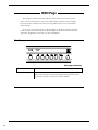
Safety Precautions
——————————————————————————————————————————
NOTE: IT IS VERY IMPORTANT THAT YOU READ THIS SECTION TO PROVIDE YEARS OF
TROUBLE FREE USE. THIS UNIT REQUIRES CAREFUL HANDLING.
——————————————————————————————————————————
• All warnings on this equipment and in the operating
instructions should be adhered to and all operating
instructions should be followed.
• This equipment should not be used near water - for
example, near a bathtub, laundry tub, in a wet
basement, near a swimming pool, etc.
• Do not use this equipment near water. Care should
be taken so that objects do not fall and liquids are
not spilled into the unit through any openings.
• All safety and operating instructions must be read
before operating this equipment. Instructions
should be retained for future use.
• The power cord to this equipment should be routed
so that it is not likely to be walked on or pinched by
items placed upon or against it. Care should be
taken as to not overload any one AC power outlet
with too may appliances. The power cord should be
unplugged from the outlet when the equipment is
left unused for a long period of time.
• All warnings on the equipment and in the operating
instructions should be adhered to, and all operating
instructions should be followed.
• This unit should be connected to a power supply
only of the type recommended by the manufacturer
as described in the operating instructions.
• Care should be taken so that objects do not fall and
liquids are not spilled into the enclosure through
any openings.
• This equipment should be situated so that its
location or position does not interfere with proper
ventilation. This equipment should be kept away
from heat sources.
• The power cord should be unplugged from the
outlet when left unused for a long period of time.
——————————————————————————————
• This unit should be serviced by qualified service personnel when:
- The power supply cord or the plug has been damaged, or
- Objects have fallen, or liquids have been spilled into the unit, or
- The unit has been exposed to rain or water, or
- The unit does not appear to operate normally or exhibits a
marked change in performance, or
- The unit has been dropped, or the enclosure damaged.
——————————————————————————————
DO NOT ATTEMPT TO SERVICE THE EQUIPMENT. THIS EQUIPMENT SHOULD BE SERVICED BY QUALIFIED
SERVICE PERSONNEL ONLY. DO NOT REMOVE THE COVER FROM THIS EQUIPMENT AT ANY TIME. DO NOT
MAKE ANY INTERNAL ADJUSTMENTS OR ADDITIONS TO THIS EQUIPMENT AT ANY TIME. DO NOT TAMPER
WITH THE INTERNAL ELECTRONIC COMPONENTS AT ANY TIME. FAILURE TO FOLLOW THESE INSTRUCTIONS
MAY VOID WARRANTY SERVICE TO THIS EQUIPMENT, AS WELL AS CAUSING SHOCK HAZARD.
Power Requirements
This unit accepts power from the 9VAC/3.4A adaptor supplied with the unit. This 9 volt RMS AC
voltage is internally processed by a voltage doubler which generates a bipolar ±15 volts to maintain the headroom and sound quality of professional, studio quality equipment. Using an external
power source such as this minimizes excessive noise and hum problems often associated with
internal transformers, providing optimal performance for the user.
Operating Temperature
Do not expose this unit to excessive heat. This unit is designed to operate between 32° F and
104° F (0° C and 40° C). This unit may not function properly under extreme temperatures.
2
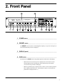
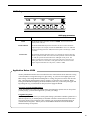
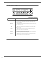
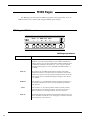
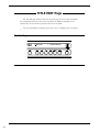
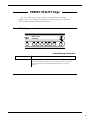
2. Front Panel
122
HOT LEAD
<- MEGA DRIVE
CHORUS->PITCH-> ----- -> -----
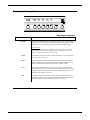
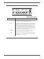
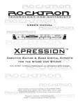
1 POWER switch
¯¯¯¯¯¯¯¯¯¯¯¯¯¯¯¯¯¯¯¯¯¯¯¯¯¯¯¯¯¯¯¯¯¯¯¯¯¯¯¯¯¯¯¯¯¯¯¯¯¯¯¯¯¯¯¯¯¯¯¯¯¯¯¯¯¯¯¯¯¯¯¯¯¯¯¯
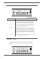
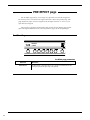
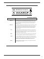
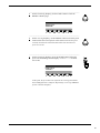
2 PRESET control
¯¯¯¯¯¯¯¯¯¯¯¯¯¯¯¯¯¯¯¯¯¯¯¯¯¯¯¯¯¯¯¯¯¯¯¯¯¯¯¯¯¯¯¯¯¯¯¯¯¯¯¯¯¯¯¯¯¯¯¯¯¯¯¯¯¯¯¯¯¯¯¯¯¯¯¯
The PRESET control is used to scroll through the Prophesy's 127 presets. Each preset is
activated automatically when it is displayed.
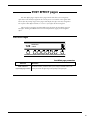
3
DISPLAY panel
¯¯¯¯¯¯¯¯¯¯¯¯¯¯¯¯¯¯¯¯¯¯¯¯¯¯¯¯¯¯¯¯¯¯¯¯¯¯¯¯¯¯¯¯¯¯¯¯¯¯¯¯¯¯¯¯¯¯¯¯¯¯¯¯¯¯¯¯¯¯¯¯¯¯¯¯
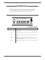
4 GAIN control
¯¯¯¯¯¯¯¯¯¯¯¯¯¯¯¯¯¯¯¯¯¯¯¯¯¯¯¯¯¯¯¯¯¯¯¯¯¯¯¯¯¯¯¯¯¯¯¯¯¯¯¯¯¯¯¯¯¯¯¯¯¯¯¯¯¯¯¯¯¯¯¯¯¯¯¯
The function of the GAIN control is dependent upon the current status of the display:
• When the title for the current preset is displayed, this control can be used to
instantly display the first Preamp page. This control then provides instant
access to the Gain parameter of that page.
• When any parameter page is displayed, this control is used to edit the parameter
that is displayed directly above it. (Note that this control is not used when no
parameters are displayed above it.)
3
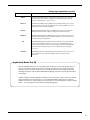
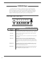
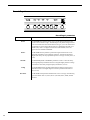
5 BASS control
¯¯¯¯¯¯¯¯¯¯¯¯¯¯¯¯¯¯¯¯¯¯¯¯¯¯¯¯¯¯¯¯¯¯¯¯¯¯¯¯¯¯¯¯¯¯¯¯¯¯¯¯¯¯¯¯¯¯¯¯¯¯¯¯¯¯¯¯¯¯¯¯¯¯¯¯
The function of the BASS control is dependent upon the current status of the display:
• When the title for the current preset is displayed, this control can be used to
instantly display the first Preamp page. This control then provides instant access
to the Bass parameter of that page.
• When any parameter page is displayed, this control is used to edit the parameter
that is displayed directly above it. (Note that this control is not used when no
parameters are displayed above it.)
6 MID control
¯¯¯¯¯¯¯¯¯¯¯¯¯¯¯¯¯¯¯¯¯¯¯¯¯¯¯¯¯¯¯¯¯¯¯¯¯¯¯¯¯¯¯¯¯¯¯¯¯¯¯¯¯¯¯¯¯¯¯¯¯¯¯¯¯¯¯¯¯¯¯¯¯¯¯¯
The function of the MID control is dependent upon the current status of the display:
• When the title for the current preset is displayed, this control can be used to
instantly display the first Preamp page. This control then provides instant access
to the Mid parameter of that page.
• When any parameter page is displayed, this control is used to edit the parameter
that is displayed directly above it. (Note that this control is not used when no
parameters are displayed above it.)
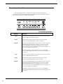
7 TREBLE control
¯¯¯¯¯¯¯¯¯¯¯¯¯¯¯¯¯¯¯¯¯¯¯¯¯¯¯¯¯¯¯¯¯¯¯¯¯¯¯¯¯¯¯¯¯¯¯¯¯¯¯¯¯¯¯¯¯¯¯¯¯¯¯¯¯¯¯¯¯¯¯¯¯¯¯¯
The function of the TREBLE control is dependent upon the current status of the display:
• When the title for the current preset is displayed, this control can be used to
instantly display the first Preamp page. This control then provides instant access
to the Treble parameter of that page.
• When any parameter page is displayed, this control is used to edit the parameter
that is displayed directly above it. (Note that this control is not used when no
parameters are displayed above it.)
8 PRESENCE control
¯¯¯¯¯¯¯¯¯¯¯¯¯¯¯¯¯¯¯¯¯¯¯¯¯¯¯¯¯¯¯¯¯¯¯¯¯¯¯¯¯¯¯¯¯¯¯¯¯¯¯¯¯¯¯¯¯¯¯¯¯¯¯¯¯¯¯¯¯¯¯¯¯¯¯¯
The function of the PRESENCE control is dependent upon the current status of the
display:
• When the title for the current preset is displayed, this control can be used to
instantly display the first Preamp page. This control then provides instant access
to the Presence parameter of that page.
• When any parameter page is displayed, this control is used to edit the parameter
that is displayed directly above it. (Note that this control is not used when no
parameters are displayed above it.)
4
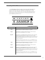
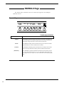
9 MASTER control
¯¯¯¯¯¯¯¯¯¯¯¯¯¯¯¯¯¯¯¯¯¯¯¯¯¯¯¯¯¯¯¯¯¯¯¯¯¯¯¯¯¯¯¯¯¯¯¯¯¯¯¯¯¯¯¯¯¯¯¯¯¯¯¯¯¯¯¯¯¯¯¯¯¯¯¯
The function of the MASTER control is dependent upon the current status of the display:
• When the title for the current preset is displayed, this control can be used to
instantly display the first Preamp page. This control then provides instant access
to the Master parameter of that page.
• When any parameter page is displayed, this control is used to edit the parameter
that is displayed directly above it. (Note that this control is not used when no
parameters are displayed above it.)
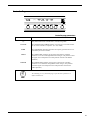
10
PAGE control
¯¯¯¯¯¯¯¯¯¯¯¯¯¯¯¯¯¯¯¯¯¯¯¯¯¯¯¯¯¯¯¯¯¯¯¯¯¯¯¯¯¯¯¯¯¯¯¯¯¯¯¯¯¯¯¯¯¯¯¯¯¯¯¯¯¯¯¯¯¯¯¯¯¯¯¯
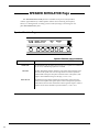
The PAGE control is used to scroll through the display pages of the current preset,
where each page displays adjustable parameters for the active effects and Prophesy
functions.
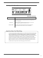
11
INput and COMPression meters
¯¯¯¯¯¯¯¯¯¯¯¯¯¯¯¯¯¯¯¯¯¯¯¯¯¯¯¯¯¯¯¯¯¯¯¯¯¯¯¯¯¯¯¯¯¯¯¯¯¯¯¯¯¯¯¯¯¯¯¯¯¯¯¯¯¯¯¯¯¯¯¯¯¯¯¯
The input meter provides a visual indication of the peak level of the input signal. For the
optimal signal-to-noise ratio, it is best to adjust the input level so that the top-most LED
(0dB) is rarely lit. This will guard against overdriving the unit.
The compression meter provides a visual indication of the level of compression currently
applied to the signal.
These meters are also used to indicate the stereo output levels when mixer function pages
are displayed.
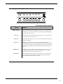
12
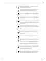
Button group
¯¯¯¯¯¯¯¯¯¯¯¯¯¯¯¯¯¯¯¯¯¯¯¯¯¯¯¯¯¯¯¯¯¯¯¯¯¯¯¯¯¯¯¯¯¯¯¯¯¯¯¯¯¯¯¯¯¯¯¯¯¯¯¯¯¯¯¯¯¯¯¯¯¯¯¯
The group of buttons to the right of the display perform various tasks, and light up to
provide a visual indication of active effects and functions. These buttons each operate as
described below.
————————————————————————————————————————————————
Allows you to compare a preset that has been modified to the original,
stored preset. This button is lit when listening to the stored version of the
preset.
————————————————————————————————————————————————
Permanently saves any changes made to a preset to Prophesy memory. This
button lights when a preset page is displayed which has one or more
parameters that have been altered from their stored values, or the preset title
page of an altered preset is displayed.
This button also lights when the Preset Utility page is displayed, indicating
that a MIDI dump or factory restore may be initiated.
5
————————————————————————————————————————————————
When pressed, switches all Prophesy effects out of the signal path. This
button is lit when the effects are bypassed.
————————————————————————————————————————————————
Fully attenuates the Prophesy outputs and activates the Prophesy built-in
tuner. This button lights when the Prophesy output is muted.
————————————————————————————————————————————————
Instantly accesses the Compressor page for the current preset. Once the
Compressor page has been displayed, this button can then be used to switch
the compressor in and out of the signal path. This button is lit when the
compressor is active.
————————————————————————————————————————————————
Instantly accesses the Wah page for the current preset. Once the Wah page
has been displayed, this button can then be used to switch the wah in and
out of the signal path. This button is lit when the wah is active.
————————————————————————————————————————————————
Instantly accesses the Phaser page for the current preset if it has been
assigned. When the Phaser page is displayed, this button can then be used
to switch the phaser in and out of the signal path. This button is lit when the
phaser effect is active.
————————————————————————————————————————————————
Instantly accesses the first Preamp page for the current preset. Once the
Preamp page is displayed, this button can then be used to switch the preamp
in and out of the signal path. When lit, the preamp is active. When not lit,
the preamp is bypassed and the signal only passes through any active
effects.
————————————————————————————————————————————————
Instantly accesses the Tremolo page for the current preset. When the
Tremolo page is displayed, this button can then be used to switch the
tremolo in and out of the signal path. This button is lit when the tremolo
effect is active.
————————————————————————————————————————————————
Switches the Loop in or out if it has been assigned.
————————————————————————————————————————————————
When pressed, looks to see if one of the three modulation effects is assigned
(flange, chorus or rotary). If the particular effect it is searching for is
assigned to the preset, the Prophesy displays the first page for that effect. If
not, displays a message indicating that the effect is not currently assigned.
Additional presses of the MODU button perform the same search for the
remaining two modulation effects.
————————————————————————————————————————————————
Instantly accesses the first Pitch Shift page for the current preset if it has
been assigned. When the first Pitch Shift page is displayed, this button can
then be used to switch the pitch shift effect in and out of the signal path. This
button is lit when the pitch shift effect is active.
————————————————————————————————————————————————
When viewing any page other than a delay or tremolo page, this button
allows you to tap the current delay time, tremolo rate, or both (depending on
the current setting of the TAPBTN parameter on the Tap button page).
6
When viewing the delay time parameter, this button allows you to tap the
current delay time.
When viewing the tremolo rate parameter, this button allows you to tap the
current tremolo rate.
————————————————————————————————————————————————
Instantly accesses the first Delay page for the current preset if it has been
assigned. When the first Delay page is displayed, this button can then be
used to switch the delay effect in and out of the signal path. This button is lit
when the delay effect is active.
————————————————————————————————————————————————
Instantly accesses the first Reverb page for the current preset. When the first
Reverb page is displayed, this button can then be used to switch the reverb
effect in and out of the signal path. This button is lit when the reverb effect is
active.
————————————————————————————————————————————————
Instantly accesses the first Mixer page for the current preset.
————————————————————————————————————————————————
13
OUTPUT LEVEL control
¯¯¯¯¯¯¯¯¯¯¯¯¯¯¯¯¯¯¯¯¯¯¯¯¯¯¯¯¯¯¯¯¯¯¯¯¯¯¯¯¯¯¯¯¯¯¯¯¯¯¯¯¯¯¯¯¯¯¯¯¯¯¯¯¯¯¯¯¯¯¯¯¯¯¯¯
The OUPUT LEVEL control determines the overall output level of the Prophesy at the
MAINOUT jacks only.
14
INPUT LEVEL control
¯¯¯¯¯¯¯¯¯¯¯¯¯¯¯¯¯¯¯¯¯¯¯¯¯¯¯¯¯¯¯¯¯¯¯¯¯¯¯¯¯¯¯¯¯¯¯¯¯¯¯¯¯¯¯¯¯¯¯¯¯¯¯¯¯¯¯¯¯¯¯¯¯¯¯¯
The INPUT LEVEL control adjusts the Prophesy's gain to match the signal level at its
input. Use the input meter (11) to determine the optimal setting of this control.
15
INPUT jack
¯¯¯¯¯¯¯¯¯¯¯¯¯¯¯¯¯¯¯¯¯¯¯¯¯¯¯¯¯¯¯¯¯¯¯¯¯¯¯¯¯¯¯¯¯¯¯¯¯¯¯¯¯¯¯¯¯¯¯¯¯¯¯¯¯¯¯¯¯¯¯¯¯¯¯¯
This standard unbalanced ¼” jack provides an input to the Prophesy. This jack has the
same function as the rear panel INPUT jack.
Note that the front and rear INPUT jacks should never be used simultaneously.
This jack should be used when plugging a guitar in and out on a regular basis. The rear
INPUT jack should be used for a permanent input connection, such as in a rack with a
wireless receiver.
7
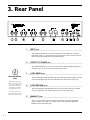
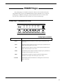
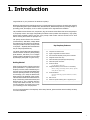
3. Rear Panel
1
INPUT jack
¯¯¯¯¯¯¯¯¯¯¯¯¯¯¯¯¯¯¯¯¯¯¯¯¯¯¯¯¯¯¯¯¯¯¯¯¯¯¯¯¯¯¯¯¯¯¯¯¯¯¯¯¯¯¯¯¯¯¯¯¯¯¯¯¯¯¯¯¯¯¯¯¯¯¯¯
This standard, unbalanced ¼" mono jack provides the same function as the front
panel INPUT jack (i.e. provides an input to the Prophesy). Please note that the front
and rear input jacks should not be used simultaneously.
2
G
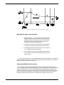
About the Effects
Loop
The Prophesy effects loop
allows you to patch a series
of one or more other effect
units into the Prophesy's
signal path at a location
determined by the user.
An example of an effects
loop configuration is shown
in Section 4: Connections.
OUTPUT TO TUNER jack
¯¯¯¯¯¯¯¯¯¯¯¯¯¯¯¯¯¯¯¯¯¯¯¯¯¯¯¯¯¯¯¯¯¯¯¯¯¯¯¯¯¯¯¯¯¯¯¯¯¯¯¯¯¯¯¯¯¯¯¯¯¯¯¯¯¯¯¯¯¯¯¯¯¯¯¯
This standard, unbalanced ¼" mono jack provides the same signal that is applied to
the INPUT jack (1) for use with an external electronic tuner.
3
LOOP SEND jacks
¯¯¯¯¯¯¯¯¯¯¯¯¯¯¯¯¯¯¯¯¯¯¯¯¯¯¯¯¯¯¯¯¯¯¯¯¯¯¯¯¯¯¯¯¯¯¯¯¯¯¯¯¯¯¯¯¯¯¯¯¯¯¯¯¯¯¯¯¯¯¯¯¯¯¯¯
The Left and Right LOOP SEND jacks provide left and right output signals to be fed
to the left and right inputs of the first outboard effects device in the effects loop.
4
LOOP RETURN jacks
¯¯¯¯¯¯¯¯¯¯¯¯¯¯¯¯¯¯¯¯¯¯¯¯¯¯¯¯¯¯¯¯¯¯¯¯¯¯¯¯¯¯¯¯¯¯¯¯¯¯¯¯¯¯¯¯¯¯¯¯¯¯¯¯¯¯¯¯¯¯¯¯¯¯¯¯
The Left and Right LOOP RETURN jacks receive the left and right output signals
from the outputs of the last outboard effects device in the effects loop.
5
MAINOUT jacks
¯¯¯¯¯¯¯¯¯¯¯¯¯¯¯¯¯¯¯¯¯¯¯¯¯¯¯¯¯¯¯¯¯¯¯¯¯¯¯¯¯¯¯¯¯¯¯¯¯¯¯¯¯¯¯¯¯¯¯¯¯¯¯¯¯¯¯¯¯¯¯¯¯¯¯¯
These ¼” mono jacks are used to connect the Prophesy to the inputs of a stereo
power amplifier. The output level of these jacks is controlled by the OUTPUT
LEVEL control on the front panel.
8
6
RECORDING OUT jacks
¯¯¯¯¯¯¯¯¯¯¯¯¯¯¯¯¯¯¯¯¯¯¯¯¯¯¯¯¯¯¯¯¯¯¯¯¯¯¯¯¯¯¯¯¯¯¯¯¯¯¯¯¯¯¯¯¯¯¯¯¯¯¯¯¯¯¯¯¯¯¯¯¯¯¯¯
These XLR connectors provide left and right output signals that are suitable to be fed
directly into a mixing console or recording device. Note that the Prophesy's Speaker
Simulation function operates only on the RECORDING OUT outputs.
The output level of these jacks is independent of the OUTPUT LEVEL control on
the front panel and is only effected by internal parameter settings. This would allow
you to adjust your stage volume through the MAINOUT jacks without changing the
level to the mixing board.
7
POWER jack
¯¯¯¯¯¯¯¯¯¯¯¯¯¯¯¯¯¯¯¯¯¯¯¯¯¯¯¯¯¯¯¯¯¯¯¯¯¯¯¯¯¯¯¯¯¯¯¯¯¯¯¯¯¯¯¯¯¯¯¯¯¯¯¯¯¯¯¯¯¯¯¯¯¯¯¯
This 4-pin DIN connector accepts power from the 9VAC adapter supplied with the
unit.
8
FOOT SWITCH jack
¯¯¯¯¯¯¯¯¯¯¯¯¯¯¯¯¯¯¯¯¯¯¯¯¯¯¯¯¯¯¯¯¯¯¯¯¯¯¯¯¯¯¯¯¯¯¯¯¯¯¯¯¯¯¯¯¯¯¯¯¯¯¯¯¯¯¯¯¯¯¯¯¯¯¯¯
This ¼” TRS jack allows for the connection of a dual function, latching-type
footswitch. One function provides the Mute function, while the other provides the
Tap Delay function.
G
About MIDI chains
Inherently in MIDI there is a
limit to the number of
devices which can be
chained together (series
connected). With more than
three devices, a slight
distortion of the MIDI signal
can occur (due to signal
degradation) which can
cause an error in MIDI
signal transmission.
Should this occur, a MIDI
box can be used which
connects directly to the
device transmitting MIDI
information. A MIDI box has
multiple connectors for the
multiple devices receiving
MIDI.
Note that MIDI cables
should not exceed 50 feet (15
meters) in length.
9
PHANTOM jack
¯¯¯¯¯¯¯¯¯¯¯¯¯¯¯¯¯¯¯¯¯¯¯¯¯¯¯¯¯¯¯¯¯¯¯¯¯¯¯¯¯¯¯¯¯¯¯¯¯¯¯¯¯¯¯¯¯¯¯¯¯¯¯¯¯¯¯¯¯¯¯¯¯¯¯¯
This jack provides the ability to power a Rocktron MIDI Mate™ foot controller from
a seven pin MIDI cable which connects from the MIDI Mate to the MIDI IN jack on
the rear panel of the Prophesy—thus eliminating the need to find an AC outlet near
where the footpedal would be placed during a performance, or the need to run an
extension cord out to the MIDI Mate.
Instead of inserting the adaptor into the MIDI Mate POWER jack, plug it into the
PHANTOM POWER jack on the Prophesy. This will power the MIDI Mate through
pins 6 and 7 of the MIDI cable connecting the two units. A 7-pin MIDI cable must
be used for this feature and is available through your Rocktron dealer.
10
MIDI IN jack
¯¯¯¯¯¯¯¯¯¯¯¯¯¯¯¯¯¯¯¯¯¯¯¯¯¯¯¯¯¯¯¯¯¯¯¯¯¯¯¯¯¯¯¯¯¯¯¯¯¯¯¯¯¯¯¯¯¯¯¯¯¯¯¯¯¯¯¯¯¯¯¯¯¯¯¯
This 7-pin DIN connector receives MIDI information from the device which is
transmitting the MIDI commands for the Prophesy to execute.
11 MIDI OUT/THRU jack
¯¯¯¯¯¯¯¯¯¯¯¯¯¯¯¯¯¯¯¯¯¯¯¯¯¯¯¯¯¯¯¯¯¯¯¯¯¯¯¯¯¯¯¯¯¯¯¯¯¯¯¯¯¯¯¯¯¯¯¯¯¯¯¯¯¯¯¯¯¯¯¯¯¯¯¯
This standard 5-pin DIN connector passes on the MIDI information that is received
at the MIDI IN jack to other MlDI-compatible devices via a MIDI cable. It also
outputs MIDI data when performing a memory dump.
9
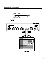
4. Connections
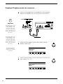
Used with a stereo power amp and stereo cabinet
10
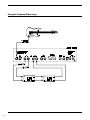
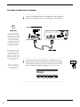
Using direct into a mixing console
11
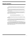
Using the Prophesy Effects Loop
12
5. Basic Operation
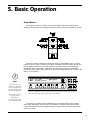
Preset Basics
The Prophesy provides 127 unique, stored sounds called presets. Each Prophesy preset
remembers effect settings, mixer settings and MIDI information which can be recalled at any time.
Presets are instantly recalled when accessed via the front panel PRESET control or a MIDI
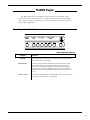
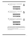
footswitch. When a preset is selected, the Prophesy will display the preset number, channel, title,
and any additional effects that have been assigned to the preset which aren't automatically
included with every preset (HUSH, compression, wah, tremolo and reverb are automatically
included with every preset). Active effects are indicated via illuminated buttons at the right of the
display, as shown below:
G
Note
The first preset page
displays any effects that
are user-assigned to the
current preset (that aren't
automatically included).
Effects that are active in
the signal path are
indicated by the
corresponding lit buttons
to the right of the display.
122
HOT LEAD
<- MEGA DRIVE
CHORUS->PITCH->
----->
-----
Figure 5-1: Display shows preset number (122), preamp channel ("Mega Drive"), preset
title ("Hot Lead") and assigned effects (Chorus, Pitch Shift).
The sound of a particular preset is dependent upon the preamp channel that is selected,
which effects are selected, and how each of those effects is configured. Each effect provides
numerous parameters that can be edited to change its characteristics, and therefore change the
sound of the preset.
13
Preset Pages
The initial information that is displayed when a preset is recalled represents the first page for
the preset. All remaining parameters for the preset (i.e. mixer parameters, effect parameters, etc.)
are located on subsequent pages which are accessible via the front panel PAGE control. Many
pages can also be instantly accessed by the corresponding buttons to the right of the display.
Each preset page displays up to six parameters for a particular effect or function, each of
which can be edited to change the sound of the preset. Note that some effects and functions
(such as reverb and the mixer) have many editable parameters, and therefore occupy numerous
successive pages.
Turning the PAGE control will scroll through the successive pages of the current preset. The
pages for each preset are organized as shown in Figure 5-2.
14
Figure 5-2: Basic layout of Prophesy preset pages
15
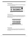
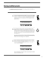
Adjusting parameters
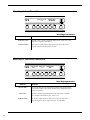
The six controls grouped directly below the display are used to edit the displayed parameter
values for each page. All display pages are configured so that each parameter can be adjusted by
the control that is located directly beneath it.
122
CHORUS LVL1
ON
-2.0
PAN1
LEFT
DLY1 DEPTH1 RATE1
88
50
25
Figure 5-3: Each displayed parameter can be adjusted by the control located
directly below it.
Instant access controls
When a preset is recalled and the preset title page is displayed, the six controls below the
display can be used to instantly access the gain, basic EQ and master volume parameters for the
current preset (Figure 5-4). Turning any of these controls when viewing the preset title page will
immediately display the first preamp page providing instant access to some of the most
commonly-edited parameters.
GAIN
8.0
BASS
5.5
MID
3.6
TREB
7.5
PRES
6.0
MASTER
6.0
Figure 5-4: Turning any of the six controls above when viewing a preset title
will instantly recall the first preamp page, allowing for instant editing of these
common parameters.
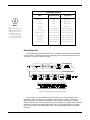
Prophesy effects
Each Prophesy preset can have up to eight effects assigned to it. Of these eight, there are
four that are always automatically assigned to every preset these are compression, wah,
tremolo and reverb. The table on the following page lists all of the effects that can be assigned
to a Prophesy preset.
16
PROPHESY EFFECTS
G
Note!
Although some effects are
automatically assigned to
each preset, they do not
necessarily have to be
active in the signal path
(i.e., they can be switched
in or out at any time).
Effect
Pre/Post Preamp
Assignment
Compressor
Pre
Automatic
Wah
Pre
Automatic
Tremolo
Post
Automatic
Reverb
Post
Automatic
Phaser
User Defined
User Assignable
4-voice Chorus
User Defined
User Assignable
Ducker Delay
User Defined
User Assignable
Pitch Shift
User Defined
User Assignable
Flanger
User Defined
User Assignable
Rotary
User Defined
User Assignable
Effect Loop
User Defined
User Assignable
Effect Configuration
Of the eight possible effects per preset, three are configured as pre-effects (located before
the gain section in the signal path) while the remaining five are post-effects (located after the
gain section), as shown in Figure 5-5 below.
Figure 5-5: Simplified Prophesy effect configuration
You can think of the pre-effects like the stomp-boxes that you would normally connect
between the guitar and the input of an amplifier (before any gain is applied to the signal)
effects like phasers, wah pedals and compressors. Post-effects are those that you would run
through the effects loop of the amp (after gain has been applied to the signal)these include the
higher-end processing units which provide effects such as reverb, delay and chorus. However,
you are free to assign any available effects to any of the user-assignable locations designated in
Figure 5-5.
17
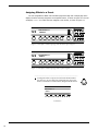
Assigning Effects to a Preset
The user-assignable Pre Effect and Post Effect pages each begin with a simple page which
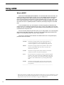
displays the effect currently assigned to the respective location, as shown in Figure 5-6. The unit
will display "EMPTY" if no effect has been assigned to the location, as shown in Figure 5-7.
122
POST EFFECT 1
CHORUS
Figure 5-6: Post Effect 1 status/assign page with the Chorus effect assigned
122
POST EFFECT 1
EMPTY
Figure 5-7: Post Effect 1 status/assign page with no effect assigned
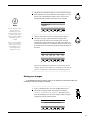
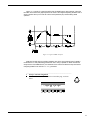
—————————————————————————————————————————————
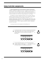
1 To assign an effect to a preset, first select the location where
the effect is to be executed in the signal path (Pre effect, Post
Effect 1, Post Effect 2 or Post Effect 3) using the PAGE control.
POST EFFECT 2
EMPTY
Continued ð
18
G
Note!
It is not necessary to store
changes made to a
particular page before
accessing another page of
the same preset, as all
changes remain in memory
until another preset is
recalled.
However, it is important to
note that any changes
made to a preset will be
lost if another preset is
recalled before those
changes are stored.
—————————————————————————————————————————————
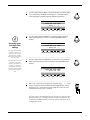
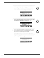
2 The display should look like Figure 5-6 if an effect has already
been assigned to the selected location, or like Figure 5-7 if one
has not. The control labeled "GAIN" can be used to scroll
through all of the available effects that can be assigned.
POST EFFECT 2
CHORUS
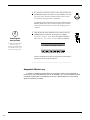
—————————————————————————————————————————————
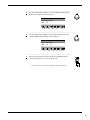
3 Once an effect has been selected, use the PAGE control to
access the next page, which will be the first page of the
selected effect. The effect can be switched in or out of the
signal path via the its button located to right of the display. If
an effect does not have its own button (such as Chorus), it can
be switched in or out via the first parameter of the first page for
the effect.
CHORUS LVL1 PAN1 DLY1 DEPTH1 RATE1
ON
0.0 100
88
50
25
Note that the modified preset must be stored in order for the
changes that have been made to be activated the next time the
preset is recalled. This is described in the following section.
—————————————————————————————————————————————
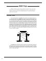
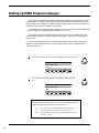
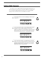
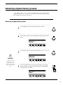
Saving your changes
A modified preset must be stored in order for the changes that have been made to be
activated the next time the preset is recalled.
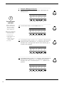
—————————————————————————————————————————————
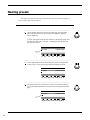
1 To save a modified preset, press the STORE button once to
initiate the storing procedure. The Prophesy will display
"SELECT DESTINATION PRESET". This allows you to
store the modified preset into a new location, while saving the
original preset at the present location.
SELECT DESTINATION PRESET
19
—————————————————————————————————————————————
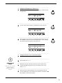
2 If you wish to save the new preset to a new preset number, use
the PRESET control to select the new preset number. Note that
the preset at the currently selected location will be written
over when the storing process is completed.
If you do not wish to store the new preset at a different preset
number, skip this step. Note that the original preset stored at
this location will be written over once the storing process is
complete.
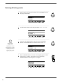
G
Cancelling the
store process
Turning the PAGE control
at any time prior to
pressing the STORE button
a second time (Step 3) will
cancel the storing process.
—————————————————————————————————————————————
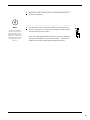
3 Once the desired preset number has been selected, press the
STORE button a second time. The Prophesy will display
"STORING PRESET NOW" as it is storing the information,
and "PRESET HAS BEEN STORED" when it is finished.
****** PRESET HAS BEEN STORED *****
Now the modified preset has been stored to the selected preset
number and can be recalled at any time.
—————————————————————————————————————————————
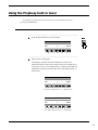
Assignable Effects Loop
In addition to assigning Prophesy effects to the locations noted as "User-assignable" in
Figure 5-5, the rear panel effects loop can also be assigned to any of these locations instead of
an internal Prophesy effect. This effectively inserts any outboard effect(s) into the Prophesy
signal path wherever you define!
20
Block Diagram
21
6. Pages and Parameters
This section details all of the pages displayed by the Prophesy and their respective parameters. Note that the pages that are accessible from any given preset is dependent upon which
effects are assigned to it, therefore not all pages discussed in this section are accessible from
every preset.
22
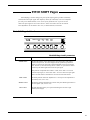
PRESET TITLE Page
The preset title page is the first page that is displayed when a preset is recalled. The
preset title and current channel are displayed on the top line, while the bottom line
indicates the effects that are currently assigned to the preset.
Preset Title Page
122
HOTLEAD
4 <--MEGA DRIVE
PHASER --> CHORUS --> DELAY --> -----
23
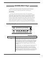
HUSH® Page
HUSH® is Rocktron's patented single-ended noise reduction system, and is available in all presets. The HUSH system provided in the Prophesy is a fully digital implementation, modeled after the latest analog HUSH design, achieved through Digital
Signal Processing (DSP).
How HUSH® works
The low level expander of the HUSH system operates like an electronic volume control. The analog version of the HUSH system utilizes a voltage-controlled amplifier (VCA)
circuit which can control the gain between the input and the output from unity gain to 30,
40 or even 50dB of gain reduction. When the input signal is above the user-set threshold
point, the VCA circuit remains at unity gain. (This means that the amplitude of the output
signal will be equal to that of the input signal.) As the input signal level drops below the
user preset threshold point, downward expansion will begin. It is at this point that the
expander acts like an electronic volume control, gradually decreasing the output signal
level relative to the input signal level. As the input signal drops further below the threshold
point, downward expansion increases (see figure below). A drop in the input level by
20dB would cause the output level to drop approximately 40dB (i.e., 20dB of gain reduction). In the absence of any input signal, the expander will reduce the gain so that the
noise floor becomes inaudible.
The HUSH circuit is located after the A/D converter in the signal chain to reduce any
noise generated from the guitar and the A/D converter. This ensures a quiet input signal to
the preamp section. Because the preamp section of the Prophesy is digital, it is virtually
noise-free (even in the high-gain mode). Therefore, a quiet input signal to the preamp will
result in a quiet output signal.
24
HUSH Page
122
HUSH
ON
H-THRES
-44dB
GLBOFFSET
-3dB
HUSH page parameters
PARAMETER
HUSH
DESCRIPTION
The HUSH parameter determines whether the HUSH® circuit is active for the
current preset. (Off, On)
HUSH THRESH
The HUSH THRESHOLD parameter determines the level at which downward
expansion begins. For example, if the HUSH THRESHOLD was set at -20dB and
the input signal dropped below -20dB, downward expansion would begin. (-90dB
to -27dB)
GLB OFFSET
The GLOBAL OFFSET parameter allows you to globally (all presets) adjust the
HUSH® expander threshold. This means that if this parameter is altered from 0dB
to +3dB, the expander threshold will become 3dB higher for all presets. This
feature is useful when switching from a quiet guitar with passive electronics to a
noisier guitar with active electronics, as the guitar with active electronics would
require a higher threshold level in all presets. (-10dB to +30dB)
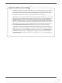
Application Notes: HUSH
You may find that the HUSH is not even needed for tones created with the Clean American voicing
or the Texas Blues voicing when using a low gain setting. As you move into a higher gain Texas
Blues setting or the Vintage British and Mega Drive voicings, the gain rises and so does the noise
floor. The higher the Gain parameter of these voicings is set, the more noise you'll hear. Before
turning on the HUSH and adjusting the HUSH threshold, make sure you have the preamp gain and
EQ settings the way you want them for that preset, then engage the HUSH.
To properly set the HUSH THRESHOLD:
Set the Threshold level so that your signal remains open during the quietest notes or decay's that
you'll be playing, yet shuts down tight when you mute your strings.
Using different guitars:
It is also important to note that if you switch guitars during a performance and those guitars have a
different output level, you should quickly use the INPUT LEVEL control on the face of the unit to
set a proper input level for each guitar. This will allow your preset HUSH Threshold settings to
work the same for all guitars. You may also use the GLOBAL OFFSET to fine tune the HUSH
Threshold settings for all presets.
25
COMPRESSOR Page
The compressor allows you to compress the signal prior to the distortion stage.
Compression is often used to maintain an even volume level when using clean tones, and
is also used to increase sustain when using distorted tones.
Compressor Page
122
C-THRESH
-22dB
C-ATTACK
C-RELEASE
16ms
.75sec
Compressor page parameters
PARAMETER
C-THRESH
The COMPRESSOR THRESHOLD parameter determines the input level (in dB)
at which compression will begin. Lower settings of this parameter will result in
more compression. (-30dB to -6dB)
C-ATTACK
The COMPRESSOR ATTACK parameter determines the speed (in milliseconds)
in which the compressor will reach its maximum compression level after the input
signal has exceeded the threshold level (set by the Compressor THRESHold
parameter). (0 to 75ms)
C-RELEASE
26
DESCRIPTION
The COMPRESSOR RELEASE parameter determines the speed in which
compression will cease after the input signal has dropped below the threshold
level. (.05sec to 2.05sec)
Application Notes: Compression
Compression is most often used when playing with a very clean tone, like in the Clean American or
Texas Blues voicings. Since there is very little or no clipping (distortion), the guitar signal will
remain very dynamic, which means that there is a lot of variance in volume levels. For example,
when you strum a chord or pick a note, it sounds very loud at first and then dies out quickly. What
compression will do is narrow the dynamic range of the signal, meaning that your strum or pluck
will not be as loud and the decay of the chord or note will be louder. The result is greater sustain
and a more even volume level.
Since the Vintage British and Mega Drive voicings have more gain, there is more clipping of the
guitar signal (distortion). This clipping of the guitar signal is actually a natural form of compression — this is the reason your chords and notes will sustain much longer using high gain than
when using a clean channel. Compression is not usually used with high gain settings, although
you can use it if you really need to get even more sustain and/or for a less dynamic effect and
sound.
Using different guitars:
It is also important to note that if you switch guitars during a performance and those guitars have a
different output level, you should quickly use the INPUT LEVEL control on the face of the unit to
set a proper input level for each guitar. This will allow your preset Compression threshold settings
to work the same for all guitars.
27
WAH Page
The Prophesy includes an internal wah-wah which can either be used as a fixed
wah or can be controlled by an expression pedal through continuous control changes.
Use of this feature eliminates the need to run long audio cables out to a conventional
wah-wah pedal.
To set up an expression pedal as a wah-wah pedal, the Prophesy must be configured
so that the expression pedal controls the "WAH FREQ" parameter described below. (See
"Controller Assignments" in Section 7 for more information.)
Wah Page
122
WAHFREQ
805HZ
Wah page parameters
PARAMETER
WAH FREQ
28
DESCRIPTION
The WAH FREQUENCY parameter allows you to manually sweep the frequency range of the wah-wah. Selecting a frequency for this parameter allows
you to use the wah-wah as a fixed wah. (310Hz to 2600Hz)
PREAMP Pages
The preamp pages are available in all presets. They are all accessible via the front
panel PAGE control, however the PREAMP button provides immediate access to the first
preamp page. In addition, turning any of the front panel instant access controls when
the preset title is displayed will also instantly access the first preamp page.
Preamp Page 1: Gain/Basic EQ Levels
122
GAIN
BASS
MID
TREB
PRES
MASTER
8.6
6.5
4.0
7.0
5.0
8.3
Preamp Page 1 parameters
PARAMETER
DESCRIPTION
GAIN
The GAIN parameter determines the amount of gain in the distortion stage.
(0.0 to 10.0)
BASS
The BASS parameter adjusts the amount of low frequency information at the
output of the current preset. (0.0 to 10.0)
MID
The MID parameter adjusts the amount of mid frequency information at the
output of the current preset. (0.0 to 10.0)
TREB
The TREBLE parameter adjusts the amount of high frequency information at
the output of the current preset. (0.0 to 10.0)
PRES
The PRESENCE parameter also adjusts the amount of high frequency
information at the output of the current preset. (0.0 to 10.0)
MASTER
The MASTER parameter determines the overall signal level of the current
preset. (0.0 to 10.0)
29
Preamp Page 2: Channel/Voicing
122
CHANNEL VOICING TYPE
1 <--CLEAN AMERICAN
V-CN RUNSTAT V-PED
17
OFF
127
Preamp Page 2 parameters
PARAMETER
DESCRIPTION
CHANNEL
The CHANNEL parameter allows you to select any of the four preamp
channels (1-4) for the current preset. The name of each channel is displayed
under the VOICING TYPE heading when selected. Available preamp
channels are Clean American, Texas Blues, Vintage British and Mega Drive.
V-CN
The V-CN parameter defines a dedicated MIDI controller number for the
Prophesy's volume. A MIDI expression pedal can be configured to match
this number and act as a volume pedal. (0-120)
RUN STAT
The RUN STAT parameter determines the current running status of the
volume pedal. If this parameter is set to "ON" and a preset is recalled, the
Prophesy will set the volume of the recalled preset to the last value it had
received from the volume pedal. When set to "OFF", the Prophesy will recall
the stored preset volume regardless of the current volume pedal position.
Once a preset has been recalled, the volume pedal can be used to change the
volume.
V-PED
The V-PED parameter displays the volume that will be used when the preset
is recalled and the RUN STAT parameter is set to "OFF".
Preamp Page 3: Pre EQ
The PRE EQ pages allow you to shape the tone prior to the distortion stage.
Considerable tone variations can be achieved by modifying these pre-distort EQ
parameters.
122
30
PRELF
PRELFF
PREMF PREMFF -> B
W
+ 1.5
101Hz
+ 7.0
1414Hz
1.7
BRIGHT
OFF
Preamp Page 3 parameters (cont'd)
PARAMETER
PRELF
DESCRIPTION
The PRE LOW FREQUENCY level parameter allows you to cut or boost the
low frequencies from -15dB to +12dB prior to the distortion stage. This EQ
section is a shelving-type. (-15.0 to +12.0)
PRELFF
The PRE LOW FREQUENCY FREQUENCY parameter allows you to select a
frequency band with an upper frequency between 63Hz and 500Hz to be cut or
boosted by the pre-LF LEVEL parameter.
PREMF
The PRE MID FREQUENCY level parameter allows you to cut or boost the
mid-band frequencies from -15dB to +12dB prior to the distortion stage.
PREMFF
The PRE MID FREQUENCY FREQUENCY parameter allows you to select a
mid-band center frequency between 63Hz and 8kHz to be cut or boosted via the
Pre Mid Frequency level parameter.
BW
The BANDWIDTH parameter determines how wide or narrow the bandwidth
of the selected mid-band frequency is (in octaves). A small bandwidth only
boosts or cuts frequencies close to the center frequency, while a large bandwidth
affects the level of frequencies up to two octaves from the center frequency.
(0.1 to 2.5)
BRIGHT
The BRIGHT parameter is displayed only when Channel 1 (Clean American) is
active, and allows you to add extra brightness to the clean channel when
switched on.
Application Notes: Pre EQ
Since the PRE EQ affects the way your guitar signal sounds before it enters the preamp stage, its
effect is most useful to influence the way the way high gain distortion tones will respond. The
more gain you use, the more distortion you get, which can decrease your pick attack. Boosting
mid-range frequencies with a medium bandwidth and dipping some bass can bring back the attack
of your pluck.
Another example of using the PRE EQ would be to create a stomp box overdrive effect by cranking
up the mid frequency level and using a very wide bandwidth while reducing the low frequency.
Another cool effect is to crank up the Pre Low Frequency Level with a Frequency setting of around
155Hz — this will produce a fuzz pedal tone if using with high gain.
31
Preamp Page 4: Post EQ
The Post EQ page allows you shape the tone after it has passed through the
distortion stage. These post-distortion EQ parameters have a more pronounced effect on
the overall tone than the pre-distortion parameters.
122
PEQ1
PEQ1F
PEQ1BW
14.0
125Hz
0.8
PEQ2
PEQ2F
- 5.5 1297Hz
PEQ2BW
1.3
Preamp Page 4 parameters
PARAMETER
PEQ1
PEQ1F
PEQ1BW
DESCRIPTION
The POST EQ 1 level parameter allows you to cut or boost a user-selected
frequency ±15dB after the distortion stage.
The POST EQ 1 Frequency parameter allows you to select a center
frequency between 63Hz and 8kHz to be cut or boosted.
The POST EQ 1 BandWidth parameter determines how wide or narrow the
bandwidth of the selected Post EQ 1 frequency is (in octaves). A small
(narrow) bandwidth only boosts or cuts frequencies close to the center
frequency, while a large (wide) bandwidth affects the level of frequencies up
to two octaves from the center frequency.
Beyond the 2.5 setting, you may also select "SHELF". The PEQ1BW
"SHELF" setting will shelve the frequencies below the center frequency. (0.1
to 2.5, Shelf)
PEQ2
PEQ2F
PEQ2BW
The POST EQ 2 level parameter allows you to cut or boost a user-selected
frequency ±15dB after the distortion stage.
The POST EQ 2 Frequency parameter allows you to select a center
frequency between 63Hz and 8kHz to be cut or boosted.
The POST EQ 2 BandWidth parameter determines how wide or narrow the
bandwidth of the selected Post EQ 1 frequency is (in octaves). A small
(narrow) bandwidth only boosts or cuts frequencies close to the center
frequency, while a large (wide) bandwidth affects the level of frequencies up
to two octaves from the center frequency.
Beyond the 2.5 setting, you may also select "SHELF". The PEQ2BW
"SHELF" setting will shelve the frequencies above the center frequency. (0.1
to 2.5, Shelf)
32
Preamp Page 5: Global EQ
The Global EQ page allows you to shape the tone at the output of the Prophesy for
all presets. This feature is useful, for example, if you are playing in a venue which
provides acoustics that would require readjustment of the EQ parameters of all the
Prophesy presets (such as needing less bass or more highs). The Global EQ parameters
allow for quickly increasing or decreasing two user-selectable frequencies for all the
presets simultaneously when necessary.
122
GEQ1
+ 2.0
GEQ1F
500Hz
GEQ1BW
1.0
GEQ2
GEQ2F GEQ2BW
- 2.0 3084Hz
1.0
Preamp Page 5 parameters
PARAMETER
GEQ1
GEQ1F
GEQ1BW
DESCRIPTION
The GLOBAL EQ 1 level parameter allows you to cut or boost a user-selected
frequency ±15dB at the output of the Prophesy for all presets.
The GLOBAL EQ 1 Frequency parameter allows you to select a center frequency between 63Hz and 8kHz to be cut or boosted.
The GLOBAL EQ 1 BandWidth parameter determines how wide or narrow the
bandwidth of the selected Global EQ 1 frequency is (in octaves). A small
(narrow) bandwidth only boosts or cuts frequencies close to the center frequency,
while a large (wide) bandwidth affects the level of frequencies up to two octaves
from the center frequency.
Beyond the 2.5 setting, you may also select "SHELF". The GEQ1BW "SHELF"
setting will shelve the frequencies below the center frequency. (0.1 to 2.5, Shelf)
GEQ2
GEQ2F
GEQ2BW
The GLOBAL EQ 2 level parameter allows you to cut or boost a user-selected
frequency ±15dB at the output of the Prophesy for all presets.
The GLOBAL EQ 2 Frequency parameter allows you to select a center frequency between 63Hz and 8kHz to be cut or boosted.
The GLOBAL EQ 2 BandWidth parameter determines how wide or narrow the
bandwidth of the selected Global EQ 1 frequency is (in octaves). A small
(narrow) bandwidth only boosts or cuts frequencies close to the center frequency,
while a large (wide) bandwidth affects the level of frequencies up to two octaves
from the center frequency.
Beyond the 2.5 setting, you may also select "SHELF". The GEQ2BW "SHELF"
setting will shelve the frequencies above the center frequency. (0.1 to 2.5, Shelf)
33
PRE EFFECT page
The Pre Effect page allows you to assign any effect that is not already assigned to
the current preset to a location in the signal chain that is before the preamp stage. This
page displays the effect currently assigned to the Pre Effect location, or "EMPTY" if no
effect has been assigned.
After an effect is assigned, the Pre Effect page becomes the first display page for that
effect. Turning the PAGE control accesses the parameter pages for the assigned effect.
Pre Effect Page
122
PREEFFECT
PHASER
Pre Effect page parameters
PARAMETER
PRE EFFECT
34
DESCRIPTION
The PRE EFFECT parameter allows you to assign an available effect to the
current preset before the gain stage of the preamp.
POST EFFECT pages
The Post Effect pages comprise three pages which each allow you to assign any
effect that is not already assigned to the current preset to a location in the signal chain
that is after the preamp stage. These pages each display the effect currently assigned to
the respective Post Effect location, or "EMPTY" if no effect has been assigned.
After an effect is assigned, each Post Effect page becomes the first display page for
that effect. Turning the PAGE control accesses the parameter pages for the assigned
effect.
Post Effect Pages
122
POST EFFECT 1
CHORUS
Post Effect page parameters
PARAMETER
DESCRIPTION
POST EFFECT 1
The POST EFFECT parameter allows you to assign an available effect to the
(repeated for pages 2 and 3) current preset after the gain stage of the preamp in the signal path.
35
FLANGER Pages
Flanging involves splitting the input signal into at least two individual delayed
signals (here referred to as Voice 1 and Voice 2), then modulating these delayed signals
so that, when summed back together with the direct signal, phase cancellations will
occur at some frequencies while peaks in the response will occur at others.
Flanger Page 1: Voice 1
122
FLANGE
ON
LVL1
PAN1
+ 3.0 L<30
DPTH1
70
RATE1
100
Flanger Page 1 parameters
36
PARAMETER
DESCRIPTION
FLANGE
The FLANGE parameter determines whether the flanger is active for the current
preset. (Off, On)
LVL1
The LEVEL1 parameter determines the volume of Voice 1 relative to Voice 2. (Off
to +6.0)
PAN1
The PAN1 parameter allows you to pan Voice 1 to the left or right channel. (Left
to Right)
DPTH1
The DEPTH 1 parameter adjusts the amount of modulation of Voice 1. Lower
DEPTH settings produce more subtle effects, while higher settings will result in a
more drastic effect. (0 to 100)
RATE1
The RATE 1 parameter determines the speed at which Voice 1 is modulated. (0 to
253)
Flanger Page 2: Voice 2
122
LVL2
+ 1.5
PAN2
RIGHT
DPTH2
65
RATE2
212
REGEN
-11.5
Flanger Page 2 parameters
PARAMETER
DESCRIPTION
LVL2
The LEVEL2 parameter determines the volume of Voice 1 relative to Voice 2. (Off
to +6.0)
PAN2
The PAN2 parameter allows you to pan Voice 1 to the left or right channel. (Left
to Right)
DPTH2
The DEPTH2 parameter adjusts the amount of modulation of Voice 1 . Lower
DEPTH settings produce more subtle effects, while higher settings will result in a
more drastic effect. (0 to 100)
RATE2
The RATE2 parameter determines the speed at which Voice 1 is modulated. (0 to
253)
REGEN
The REGENERATION parameter determines how much of the delayed output
signal is fed back into the input. More regeneration produces a more pronounced
"jet airplane" type of effect. (Off, -42.0 to 5.0)
37
CHORUS Pages
The Chorus effect in the Prophesy is produced by using up to four delayed signals
(referred to here as Voices 1-4), detuning these delayed signals (slightly changing their
pitch), then modulating the detune effect so that the amount of pitch detune is constantly
varying. Using different detune amounts, modulation rates, modulation depths and pan
settings for each delayed signal will produce a greater perceived spaciousness.
Chorus Pages 1 and 2: Voices 1 and 2
122
CHORUS
LVL1
PAN1
DLY1
ON
- 2.0
L<26
68
DEPTH1 RATE1
50
125
Chorus Pages 1 and 2 parameters
38
PARAMETER
DESCRIPTION
CHORUS
The CHORUS parameter determines whether the Chorus is active or bypassed
for the current preset. (This parameter is displayed only on Page 1.) (Off, On)
LVL1 and 2
The LEVEL parameter determine the volume of Voice 1 relative to the other
voices. (Off, -42.0 to +6.0)
PAN1 and 2
The PAN parameter allows for Voice 1 to be panned to the left or right channel.
(Left to Right)
DLY1 and 2
The DELAY parameter allows you to select the minimum delay time (in
milliseconds) for Voice 1. This delayed signal is detuned and modulated to
produce the chorus effect. Shorter delay times will result in a tighter sounding
chorused signal, while longer delay times will produce a larger ambient effect. (0
to 100)
DEPTH1 and 2
The DEPTH parameter adjusts the amount of modulation of Voice 1. A lower
depth setting will produce a more subtle detune effect, while a higher setting
results in a more extreme detuning. (0 to 58)
RATE1 and 2
The RATE parameter determines the sweep speed (or the speed at which each
voice is modulated). Lower parameter settings result in slower speeds, while
higher settings result in faster speeds. (0 to 253)
Chorus Pages 3 and 4: Voices 3 and 4
122
REGENL
OFF
LVL3
OFF
PAN3
58>R
DLY3
0
DEPTH3 RATE3
0
0
Chorus Pages 3 and 4 parameters
PARAMETER
DESCRIPTION
REGEN L (page 3)
REGEN R (page 4)
The REGENERATION LEFT parameter determines how much of the delayed
output signal is fed back into the left input. Note that voice 3 has a REGEN L
parameter, while voice 4 has a REGEN R for providing regeneration through the
right input. (Off, -42.0 to +6.0)
LVL3 and 4
The LEVEL parameter determines the volume of the current voice relative to the
other chorus voices. (Off, -42.0 to +6.0)
PAN3 and 4
The PAN parameter allows for the current voice to be panned to the left or right
channel. (Left to Right)
DLY3 and 4
The DELAY parameter allows you to select the minimum delay time (in
milliseconds) for the current voice. This delayed signal is detuned and modulated
to produce the chorus effect. Shorter delay times will result in a tighter sounding
chorused signal, while longer delay times will produce a larger ambient effect. (0
to 100)
DEPTH3 and 4
The DEPTH parameter adjusts the amount of modulation of the current voice. A
lower depth setting will produce a more subtle detune effect, while a higher
setting results in a more extreme detuning. (0 to 58)
RATE3 and 4
The RATE parameter determines the sweep speed (or the speed at which each
voice is modulated). Lower parameter settings provide slower speeds, while
higher settings result in faster speeds. (0 to 253)
39
ROTARY Page
The Rotary effect simulates the classic rotating speaker popular with guitarists and
keyboard players. It is designed to mimic the characteristics of the mechanical rotating
speaker with added versatility afforded by DSP.
Rotary Page
122
ROTSPK RSPEED SLOWSP FASTSP
ON
SLOW
45
80
ACCEL
ROTBAL
100
81>H
Rotary page parameters
PARAMETER
DESCRIPTION
ROTSPK
The ROTARY SPEAKER On/Off parameter determines whether the Rotary
effect is active or bypassed for the current preset.
Note that even when this parameter is set to OFF, the rotary effect is still
present, meaning that it will still sound like you're playing through a rotary
speaker cabinet, but with no rotary action. When turned off, the sound will vary
as the rotaries will not always come to rest in the same position, just like in a real
rotary cabinet. (Off, On)
RSPEED
The ROTATION SPEED parameter switches between the SLOWSP and
FASTSP setting. (Slow, Fast)
SLOWSP
The SLOW SPEED parameter sets the slow rotation speed. (The horn and rotor
will rotate at slightly different speeds.) (0 to 100)
FASTSP
The FAST SPEED parameter sets the fast rotation speed. (0 to 100)
ACCEL
The ACCELERATION parameter adjusts the length of time it takes to reach the
SLOW SPeed or FAST SPeed setting of both the horn and rotor. (The horn will
accelerate faster than the rotor). (0 to 100)
ROTBAL
40
The ROTATION BALANCE parameter adjusts the relative level of the rotor
(lows) vs. the horn (highs). (Rotor to Horn)
Application Notes: Rotary
The Rotary effect included in the Prophesy has been designed to provide the most realistic
simulation of an actual rotary speaker as possible. However, the nature of the rotary effect requires
a significantly higher amount of processor power than any of the other effects included in the
Prophesy in order to implement it without sacrificing the quality of the effect.
As a result of this, it is important to note that using all three modulation effects (rotary, flanger,
chorus) and the phaser effect simultaneously can result in an overload of the Prophesy's internal
processor—causing a significant hum and loss of sound quality. For this reason, it is recommended
that simultaneous usage of all three modulation effects is avoided to greatly reduce the chances of
this condition occurring.
41
PHASER Page
Phase shifting involves splitting the input signal into two signals, then shifting the
phase of different frequencies of one signal and mixing it back with the original signal.
Phaser Page
122
PHASER> DEPTH
55
RATE
RESON
STAGES
143
25
4
Phaser page parameters
PARAMETER
DEPTH
The DEPTH parameter determines the modulation depth of the phase shift
effect. Higher parameter settings result in the sweep of the filtering effect
occurring over a wider frequency range. (0 to 100)
RATE
The RATE parameter determines the speed at which the phase shifted signal is
modulated. (0 to 253)
RESONANCE
The RESONANCE parameter adds feedback to the Phaser so that it has a more
pronounced effect. (0 to 100)
STAGES
42
DESCRIPTION
The STAGES parameter determines how many stages of phase shift are to be
active. A parameter setting of “4” produces a result similar to a vintage Phase 90,
while a setting of “6” emulates other phaser pedals. (4, 6)
PITCH SHIFT Pages
Pitch Shifting is used to change the pitch of the input signal to produce a harmony
note based on the input signal. The Prophesy allows for 2 harmony voices to be defined
for each preset. Each harmony voice can be of any fixed interval—up to one octave
above the input signal to two octaves below—and is selected in 20-cent increments.
Fine adjustment can be made in one cent (1/ 100th semitone) increments.
Pitch Shift Page 1: Voice 1
122
PSHIFT> PITCH 1 FINE 1 LEVEL 1 PAN 1
79>R
+500
+12
+2.5
Pitch Shift Page 1 and 2 parameters
PARAMETER
PITCH 1 and 2
DESCRIPTION
The PITCH parameter selects what harmony note the Prophesy will produce
based on the input note. The value displayed for this parameter represents the
number of cents that the signal will be shifted (adjustable in 20-cent increments).
Each 100 cents (or five 20-cent steps) above or below “0” represents the number
of half-steps the shifted signal will be from the input signal.
This parameter is adjustable from -2400 to +1200, where -2400 = two octaves
below the input signal, 0 = unison and +1200 = one octave above the input signal.
Refer to the table below to determine the cent value for each fixed interval.
FINE 1 and 2
The FINE parameter allows for adjustment in 1-cent steps for fine adjustment of
the harmony note. (-20 to +20)
LEVEL 1 and 2
The LEVEL parameter determines the volume of the pitch shifted signal relative to
the other signals. (Off, -42.0 to +6.0)
PAN 1 and 2
The PAN parameter allows you to pan the shifted signal to the left or right
channel. (Left to Right)
43
Pitch Shift Intervals
PITCH PARAMETER
+1200
+1100
+1000
+900
+800
+700
1 Octave
Major 7th
minor 7th
Major 6th
minor 6th
perfect 5th
+600
+500
+400
+300
+200
+100
diminished 5th
perfect 4th
Major 3rd
minor 3rd
Major 2nd
minor 2nd
0
unison
Above input note
"
"
"
"
"
"
"
"
"
"
"
Equal to input note
-100
-200
-300
-400
-500
-600
Major 7th
minor 7th
Major 6th
minor 6th
perfect 5th
diminished 5th
-700
-800
-900
-1000
-1100
-1200
perfect 4th
Major 3rd
minor 3rd
Major 2nd
minor 2nd
1 octave
"
"
"
"
"
"
-1300
-1400
-1500
-1600
-1700
-1800
1 octave plus a Major 7th
1 octave plus a minor 7th
1 octave plus a Major 6th
1 octave plus a minor 6th
1 octave plus a perfect 5th
1 octave plus a diminished 5th
"
"
"
"
"
"
-1900
-2000
-2100
-2200
-2300
-2400
1 octave plus a perfect 4th
1 octave plus a Major 3rd
1 octave plus a minor 3rd
1 octave plus a Major 2nd
1 octave plus a minor 2nd
2 octaves
"
"
"
"
"
"
"
G
Note!
44
CORRESPONDING INTERVAL (RELATIVE TO INPUT NOTE)
Below input note
"
"
"
"
"
There are 5 steps of the parameter adjust control between each of the intervals
shown above (each step equals 20 cents). This allows for smooth pitch changes
when an expression controller is assigned to the PITCH parameter to change the
pitch by remote means.
DUCKER/DELAY Pages
Delay is a repeat of the guitar signal, which will repeat at the time the user sets
(typically expressed in milliseconds) after the original guitar signal. The Prophesy
provides several parameters to adjust the characteristics of the delay effect.
About Ducking
The Delay effect also has a built-in Ducker function. The word "ducking" is
another way to say that you're turning down the volume level of the delay (or "attenuating" the delay). When using the ducker, the volume of the delay would be attenuated, or
"ducked" while playing so that it was quieter than your original played notes and,
therefore, would not compete with your played notes. When you stop playing, the ducker
will release and the volume level would then come back to full volume and echo out nice
and loud. The Ducker effect does this for you automatically! This is a great effect for
soloing. When the ducker is adjusted correctly, you can have the delay mixed just right
behind your played notes and have nice loud and long trail-offs when you stop playing.
Delay Page 1: Delay Time, Level
122
MUTE
PRE
SPILOVR LEVEL
OFF
0.0
PAN
75>R
D-TIME 1 REGEN
116
+3.5
Delay Page 1 parameters
PARAMETER
MUTE
DESCRIPTION
The MUTE parameter allows for muting of the Delay section at its input (PRE),
its output (POST) or both pre and post (BOTH). (The MUTE function is
actually switching the Delay IN and OUT — just like you would with the Delay
button on the front panel. It can be accessed with a MIDI pedal by sending the
Prophesy a MIDI control number of your choice and assigning that same MIDI
control number to the DELAY-IO parameter in any of the Prophesy's eight
Controller Assignments. See "Controller Assignments" in Section 7 for more
information.)
When using the MUTE "PRE" setting, the Delay IN/OUT function will start and
stop the guitar signal before it enters the delay effect. This will produce the
following results: When you switch the delay "OUT" while you're playing, the
guitar signal will be stopped from entering the delay effect at its input and the
last few notes you were playing will trail off until there is no more delayed signal.
When switching the delay "IN", signal will begin to enter the delay effect and will
then start to be delayed from the exact point at which you turn the delay on.
45
Delay Page 1 parameters (cont'd)
PARAMETER
DESCRIPTION
When using the MUTE "POST" setting, the Delay IN/OUT function will start
and stop the guitar signal at the delay effect's output. This will produce the
following results: When you switch the delay "OUT" while you're playing, the
delayed signal will suddenly be chopped off and will no longer be heard. The
delay effect's input, however, is still receiving signal. So, when you switch the
Delay "IN" while playing, any licks you were playing will already be echoing and
will then be heard.
When using the MUTE "BOTH" setting, the Delay IN/OUT function will start
and stop the guitar signal at the delay effect's input and output. This will
produce the following results: When you switch the delay "OUT" while you're
playing, the delayed signal will suddenly be chopped off and will no longer be
heard. When switching the delay "IN", the signal will begin to enter the delay
effect and will then start to be delayed from the exact point at which you turn the
delay on.
SPILOVR
The SPILOVR parameter determines whether delays from the current preset will
"spill over" into the next preset when it is recalled. If this parameter is set to
"OFF", delays from the current preset will be immediately cut off when another
preset is recalled.
When this parameter is set to "ON", it enables the current delay to "spill over" to
the next preset. However, note that in order for the spillover to work, the Delay
effect must be assigned to any of the effect assignments in the next preset that you
switch to. Also, the Delay SPILOVR parameter must be stored as "ON" in that
next preset. You do NOT have to have the delay stored as "ON" in the next preset
unless you want to. For example, this can create a very smooth transition from a
very long lead solo delay into a nice short rhythm delay, where the long delay
trails out as the new shorter delay has already begun. If Delay has not been
assigned in the next preset that you switch to, the spillover will not work.(Off,
On)
LEVEL
PAN
46
The LEVEL parameter determines the overall level of the delayed signal at the
output relative to the direct signal and other effect signals. (Off, -42.0 to +6dB)
The PAN parameter allows for the delayed signal to be panned to the left or right
channel. (Left to Right)
D-TIME
The DELAY TIME parameter determines the length of time (in milliseconds)
after the input signal that the delayed signal will begin. (0 to 988)
REGEN
The REGENERATION parameter determines the number of times that the
delayed signal will repeat itself. This is achieved by feeding the delayed output
back into the input. Higher parameter settings will result in more repeats. The
displayed value represents the attenuation (in dB) that the regeneration signal is
subjected to at each repeat. (Off, -42.0 to +6dB)
Delay Page 2: Damping/Ducker
122
HFDAMP
DUCK
SENS
ATTN
REL
PRE
ON
-36.0
-23.0
5
Delay Page 2 parameters
PARAMETER
DESCRIPTION
HF DAMP
The Delay HIGH FREQUENCY DAMPING parameter controls the amount of
high frequency content in the delayed and regenerated signals. Higher amounts of
damping will result in less high frequency information in the delayed signal.
Application Note:
Using little or no High Frequency Damping will render a perfect, mirror like
delay. Medium to high amounts of High Frequency Damping will produce a
duller, more tape echo-like delay sound. (0 to 99)
DUCK
The DUCKER parameter determines whether the Ducker is active or muted for
the current preset. (Off, On)
SENS
The SENSITIVITY parameter determines the threshold point above which the
ducker will begin attenuating the delay signal. Until the input reaches this level,
the delay signal will not be affected by the ducker. (-92dB to -20dB)
ATTN
The ATTENUATION parameter determines how much the delayed signal is
attenuated (muted). It may be set for only a slight change in signal level or it can
completely attenuate the delayed signal so that no delayed signal passes while
ducking is active. (INFIN, -48 to -0.0)
REL
The RELEASE parameter determines the length of time it takes for the for the
muted delay signal to return to its original level after the input signal falls below
the threshold point set by the SENSitivity parameter. (.2 to 9.0)
47
TREMOLO Page
The Tremolo effect continuously varies the volume of the signal at a rate and depth
defined by the user.
Tremolo Page
122
TREM> T-DPTH T-RATE T-SHAPE
60
103
TRIANGLE
{TREMOLO}
PST-REV
Tremolo page parameters
PARAMETER
48
DESCRIPTION
T-DPTH
The TREMOLO DEPTH parameter determines the amount of modulation for
the Tremolo signal. Lower depth settings produce more subtle tremolo effects,
while higher settings will result in a more extreme tremolo effect.
T-RATE
The TREMOLO RATE parameter determines the speed at which the tremolo
signal modulates (or increases and decreases in volume).
T-SHAPE
The TREMOLO SHAPE parameter determines the waveshape of the tremolo
signal. Selecting a different waveshape produces a different tremolo effect.
{TREMOLO}
The {TREMOLO} parameter determines whether the tremolo effect is before
(PRE-REV) the reverb or after it (PST-REV) in the effects chain. Refer to the
block diagram shown in Chapter 5 for more information on the Prophesy signal
path.
REVERB Pages
Reverb is a multitude of echoes that are spaced so close together that, to human
ears, seem as a single continuous sound. These echoes gradually decrease in intensity
until they are ultimately absorbed by the boundaries and obstacles within a room. As
the sound waves from the sound source strike the boundaries of a room, a portion of the
energy is reflected away from the obstacle while another portion is absorbed into it —
thereby causing both the continuance of sound as well as the decaying or “dying out”
of the sound.
Reverb Types
The Prophesy provides the following types of reverb:
The Plate reverb type simulates an artificial method of producing reverberation,
popular in the early years of recording, which involved using a fairly large, but
very thin, metal plate suspended at its four corners by steel wires under
tension. This metal plate becomes excited by a driver unit (similar to a dynamic
speaker without the diaphragm) and the resulting reverberation is picked up by
contact microphones.
The Prophesy offers two Plate reverb types which reflect the most common
plate characteristics. This type of reverb is often used on drum and vocal tracks.
Room reverb effects simulate various rooms of different sizes and surfaces. For
example, a room which is made up of primarily hardened surfaces (such as tile
or hard wood) will generate reflections containing much more high frequency
information than one which is made up of softer surfaces (such as thick
carpeting). The Room reverb effects provided by the Prophesy can generate
virtually any imaginable room setting via highly efficient and adjustable reverb
parameters.
Hall reverb simulates the reverberation characteristics of a very large room with
a high ceiling. Reflections in a hall are much longer than a typical room, as the
length of time it takes for the sound waves to travel from one surface to the
next is greatly increased.
Stadium reverb simulates the characteristics of a large stadium or arena and
should be used with large amounts of predelay and high frequency damping.
Dual reverb is unique in that it allows for the left and right channels to be
processed independently of one another. For example, the predelay for the left
channel can be set at 100mS while the Predelay for the right channel can be
set at 200mS. This results in reverb output from the left channel 100mS before
reverb is output from the right channel.
49
Reverb Page 1:
122
R-PAN
R-DEC
HFDMP
L-FRQ
REVTYPE
L<29
30
88
17
HALL A
Reverb Page 1 parameters
PARAMETER NAME
R-PAN
The REVERB PAN parameter allows you to pan the direct input signal to the
reverb section to the left or right—thus allowing for only the left or right channel
to be reverberated when used with the Dual reverb type, or, for one channel to be
reverberated to a greater degree than the other. It is adjustable from LEFT (0) to
RIGHT (100), where 1-49 appear between LEFT and CENTER, and 51-99
appear between CENTER and RIGHT.
R-DEC
The REVERB DECAY parameter specifies the length of time that the reverb
signal will sound before it has completely "died out". Note that the maximum
length of this decay will vary dependent upon the reverb type currently active. (0
to 99)
HFDMP
The HIGH FREQUENCY DAMPING parameter is used to control the decay
rate of high frequency information in the reverb signal. Higher parameter settings
will result in a faster decay of high frequency information. (0 to 99)
L-FRQ
REV TYPE
50
DESCRIPTION
The LOW FREQUENCY parameter determines the amount of low frequency
information in the reverb signal. Higher levels of this parameter add more low
end. (0 to 99)
The REVERB TYPE parameter determines the active reverb type. The following
types are available: Plate A, Plate B, Room A, Room B, Hall A, Hall B, Stadium
and Dual.
Reverb Page 2:
122
PREDLYL PREDLYR
55
100
GATE
G-DEC
G-THR
HOLD
ON
17
-26.0
50
Reverb Page 2 parameters
PARAMETER NAME
DESCRIPTION
PREDLY L
The PREDELAY LEFT parameter determines the length of time after a signal is
input to the Prophesy that the left channel signal will be input to the reverb
section. Delaying the reverb signal provides greater separation of the input and
reverb signals, and helps to increase the perceived size of the Room, Hall or
Stadium. (0 to 198)
PREDLY R
The PREDELAY RIGHT parameter determines the length of time after a signal is
input to the Prophesy that the right channel signal will be input to the reverb
section. Delaying the reverb signal provides greater separation of the input and
reverb signals, and helps to increase the perceived size of the Room, Hall or
Stadium. (0 to 198)
GATE
The GATE parameter closes down the decay of the reverb very quickly after a
prescribed amount of time (most commonly a very short period of time). Note
that the gating on the Prophesy acts on the reverb decay, rather than the reverb
output as on many other units. (Off, On)
G-DEC
The GATE DECAY parameter determines how quickly the gate will close down
the reverb decay after the reverb has sounded for the specified time. (0 to 31)
G-THR
The GATE THRESHOLD determines the signal level at which gating will take
place. When the signal remains below this threshold level for the specified HOLD
time, the reverb will be gated. When the input signal peak rises above this
threshold, the gate will open and reverb will be heard. (Off, -42.0 to +6.0)
HOLD
The HOLD parameter determines how long the reverb signal will sound before
the gate begins to close. (0 to 99)
51
SPEAKER SIMULATOR Page
The SPEAKER SIMULATOR function is available in all presets, and provides a
realistic approximation of a miked speaker cabinet when connecting the Prophesy
directly to a mixing board, recording system or other full range system using the rear
panel RECORDING OUT jacks.
Speaker Simulator Page
122
SPEAKER>> SPKRTYPE
SIMULATOR> 12 INCH
MICPOS
REACTANCE
+8.0
+3.0
Speaker Simulator page parameters
PARAMETER
SPKR TYPE
52
DESCRIPTION
The SPEAKER TYPE parameter determines the type of speaker to be simulated.
15”,12”,10”, 8” and full range speakers are available.
MIC POS
The MIC POSITION parameter simulates a microphone placed anywhere from
the center of the speaker cone out to the edge of the cone. Positive parameter
values simulate moving the microphone toward the center of the speaker, while
negative values simulate moving it to the edge. (-15.0 to +15.0)
REACTANCE
The REACTANCE parameter simulates the characteristics of the interaction
between a tube amplifier and a guitar speaker cabinet. The higher the parameter
value selected, the more these characteristics will be apparent. Negative values of
reactance can be used to simulate an open-back cabinet. (-15.0 to +15.0)
MIXER Pages
The Mixer parameters are included in all presets. However, the parameter values
stored in these pages pertain only to the currently-recalled preset. This internal digital
mixer occupies five pages, and allows you to control the signal levels pertaining to each
preset's effect configuration.
Mixer Page 1: Pre Effect Mix Levels
122
(PRE MIX)
(PRE EFX OUT)
(EFFECT USED)
57>E
- 3.0
PHASER
Mixer Page 1 parameters
PARAMETER
DESCRIPTION
PRE MIX
The PRE MIX parameter determines the direct/effect mix from the Pre Effect
block. (100% Direct to 100% Effect)
PRE EFX OUT
The EFX OUTPUT parameter determines the overall level that is output
from the Pre Effect block. Note that this parameter acts like an overall
volume control, and affects the signal level for the remainder of the signal
path. Please refer to the Block Diagram shown at the end of Section 5 for a
visual indication of how this parameter is used in the signal path. (Off, -42.0
to +6.0)
EFFECT USED
The EFFECT USED parameter indicates the effect that is currently assigned
to the Pre Effect location, if any. (Not adjustable)
53
Mixer Page 2: Post Effect 1 Mix Levels
122
(PST1 EFX 1 OUT)
(EFFECT USED)
+ 1.5
DUCKERDELAY
Mixer Page 2 parameters
PARAMETER
PST1 EFX 1 OUT
EFFECT USED
DESCRIPTION
The PST1 EFX 1 OUTPUT parameter determines the output level of the
effect that is assigned to Post Effect 1.
The EFFECT USED parameter displays the name of the effect that is
currently assigned to the Post Effect 1 location.
Mixer Page 3: Post Effect 2 Mix Levels
122
(PST2-IN MIX) (EFX 2 OUT)
D<40
-13.0
(EFFECT USED)
ADSR
Mixer Page 3 parameters
PARAMETER
PST2-IN MIX
EFX 2 OUT
EFFECT USED
54
DESCRIPTION
The PST2-IN MIX parameter determines how much of the signal applied to
the Post Effect 2 effect is direct signal, and how much is effect signal. (100%
Direct to 100% Effect)
The EFX 2 OUTPUT parameter determines the output level of the effect
that is assigned to Post Effect 2. (Off, -42.0 to +6.0)
The EFFECT USED parameter displays the name of the effect that is
currently assigned to the Post Effect 2 location. (Not adjustable)
Mixer Page 4: Post Effect 3 Mix Levels
122
(PST3-IN MIX)
DIRECT
(EFX 3 OUT)
OFF
(EFFECT USED)
EMPTY
Mixer Page 4 parameters
PARAMETER
PST3-IN MIX
EFX 3 OUT
EFFECT USED
DESCRIPTION
The PST3-IN MIX parameter determines how much of the signal applied to
the Post Effect 3 effect is direct signal, and how much is effect signal. (100%
Direct to 100% Effect)
The EFX 3 OUTPUT parameter determines the output level of the effect
that is assigned to Post Effect 3. (Off, -42.0 to +6.0)
The EFFECT USED parameter displays the name of the effect that is
currently assigned to the Post Effect 3 location. (Not adjustable)
Application Notes: Post Effect Mixing
The PST2-IN MIX and PST3-IN MIX parameters act as a balance between the direct and effect that
is entering the assigned effect of Post effect blocks 2 and 3. For example, lets say that DUCKER/
DELAY is assigned to Post 1 effect block and that CHORUS is assigned to Post 2 effect block.
Adjusting the PST2-IN MIX parameter to 100% DIRECT would cause only the direct guitar tone to
be chorused while the delayed signal would not be chorused. Adjusting the PST2-IN MIX
parameter to 100% EFFECT would cause only the delayed signal to be chorused while the direct
guitar tone would not be chorused. Adjusting the PST2-IN MIX parameter anywhere between
DIRECT and EFFECT would cause a blend of the direct and the delayed signal to be chorused.
The REV IN (Reverb in) parameter on the following page works the same way.
55
Mixer Page 5: Reverb Mix Levels
122
REV IN REVOUT DIR
62>E
- 5.5 - 1.0
DPAN
L<37
OUTPUT PLEVEL
STEREO
25
Mixer Page 5 parameters
PARAMETER
REV IN
The REVERB INPUT parameter determines how much of the signal applied
to the reverb section is direct signal, and how much is effect signal. (100%
Direct to 100% Effect)
REV OUT
The REVERB OUTPUT parameter determines the output level of the reverb
effect. (Off, -42.0 to +6.0)
DIR
DPAN
56
DESCRIPTION
The DIR parameter determines the overall output level of the direct signal.
(Off, -42.0 to +6.0)
The DPAN parameter is used to pan the direct signal to the left or right
Prophesy output. (100% Left to 100% Right)
OUTPUT
The OUTPUT parameter determines whether the output of the Prophesy is
a stereo (left and right) signal or two mono signals.
PLEVEL
The PRESET LEVEL parameter determines the overall output level of the
current preset relative to the other Prophesy presets.
Application Notes: Reverb Mixing
The DIR (Direct) parameter actually controls the volume of the DRY guitar signal (with no effect) at
the output. This can become very useful when attempting to get a wetter effect sound — rather
than cranking up all your effects levels, simply turn down the DIR parameter to remove some dry
guitar signal. The result will be thicker, richer sounding chorus, rotary, flanger, etc.
The OUTPUT control is global, which means that it effects all presets. When set to "STEREO", all
effect and direct signal panning will be directed toward their respective Left and Right Recording
and Main outputs. The "STEREO" setting should be used when connecting the left and right
outputs to individual channels of a stereo power amp and then to a stereo speaker cabinet. When
set to "MONO", all effect and direct panning is ignored and all signals are directed to the Left and
Right outputs evenly. Use the "MONO" setting and either the Left or Right output for use with a
mono amp head and non stereo speaker cabinet, or when you wish to mic only one speaker.
The PLEVEL (Preset Level) control should be used only for additional preset level matching. The
MASTER control of the first Preamp page is your first and most easily accessible level setting for
each preset, however, you may find that some clean presets with a very low gain setting are very
quiet, even with the master set to 10. High gain presets will be much louder in relation to these
ultra-clean presets. This parameter simply gives you an added preset level control in addition to
your channel masters.
57
CONTROLLER Pages
Controller assignments allow for specified Prophesy parameters to be mapped (or
assigned) to a MIDI controller for real-time control by an expression pedal or by the
controller on/off buttons of a MIDI foot controller. In addition to 120 MIDI control
numbers, you may assign the Prophesy's ADSR (Attack/Sustain/Decay/Release) control
effect to any parameters with these controller assignments (ADSR is discussed further in
Section 7, Using the ADSR).
Controller assignments also allow you to store an upper and lower parameter value
limit which the controller cannot exceed. For example, when using the expression pedal
to send continuous control changes to control the “PITCH 1” parameter, an upper
limit of +300 can be set and a lower limit of -200 can be set—even though the actual
parameter range is from +1200 to -2400. When the expression pedal is at its heel
position in this example, the “PITCH 1” parameter will be at -200, while at its toe
position it will be at +300. (Refer to Section 7: “Using the Prophesy” for information on
setting up controllers.)
Up to eight controllers can be assigned for each individual preset, and each one has
its own display page.
58
Controller Pages
122
( 1 )
CNTNUM PARM
14
PITCH1
UPLIM
+300
LOWLIM
-200
Controller page parameters
PARAMETER
(1)
DESCRIPTION
This number indicates the controller that is currently being edited.
CNTNUM
The CONTROLLER NUMBER parameter is used to select a controller number
for the current controller to respond to. (0 to 120, ADSR)
PARM
The PARAMETER parameter determines the Prophesy parameter that is to be
controlled by the current controller.
UPLIM
The UPPER LIMIT parameter sets the highest value that the controlled
parameter is not to exceed through MIDI control changes. (The parameter values
that appear here will depend on the actual parameter selected in the PARM
parameter.)
LOWLIM
G
The LOWER LIMIT parameter sets the lowest value that the controlled
parameter is not to fall below through MIDI control changes. (The parameter
values that appear here will depend on the actual parameter selected in the
PARM parameter.)
The remaining seven (7) Controller pages repeat the above parameters to
define controllers 2-8.
Note
59
TAP BUTTON Page
The Tap Button function allows for delay times and tremolo rates to be set by
tapping the front panel TAP button, by a momentary footswitch connected to the rear
panel, or by a control button on a MIDI foot controller like the Rocktron All Access.
Obviously, this is very handy for quickly getting the proper Delay times and/or Tremolo
rates for different song tempos.
The Tap Button page determines which effects that the Tap function will operate on.
The Tap function can work with the Delay time, the Tremolo rate, or both simultaneously. These settings will work the same for the front panel Tap button, a momentary
footswitch connected to the footswitch jack, or control messages sent by a MIDI foot
controller.
It is also important to note that: The TAPBTN (Tap Button) parameter settings of
DELAY, TREM or BOTH will only operate as set when viewing any other page except the
delay or tremolo pages. So, for example, if the TAPBTN parameter is set to BOTH and
you're presently viewing the preset title page, and you were to begin tapping the TAP
button, the Delay time and Tremolo speed will be adjusted simultaneously. However, if
you then turn to the Delay page and begin tapping the TAP button, it will effect the
Delay time only. Likewise, viewing the Tremolo page and tapping the TAP button will
effect the Tremolo rate only.
60
Tap Button Page
122
TAPBTN QUANT
BOTH 1/4 NOTE
T-CTRNUM
15
T-LED
OFF
Tap Button page parameters
PARAMETER
DESCRIPTION
TAPBTN
The TAPBTN parameter allows you to select whether the front panel Tap
button, momentary footswitch, or MIDI controller affects the Delay time,
the Tremolo rate or both simultaneously. (Delay, Trem, Both)
QUANT
The QUANTize parameter determines how the Tap function sets the delay
time and the tremolo rate. For example, when set to "1/4 NOTE", the delay
time will be set to match the same tempo that you tapped. When set to "1/
8 NOTE", the delay time will be twice as fast as the tempo that you tap.
Likewise, the Tremolo rate may be quantized in the same fashion, allowing
one to quickly get the proper tremolo rate for the tempo of a particular song.
What if I want a 1/16 note? Simply multiply a 1/8 note tapped speed or rate
value by 2 and adjust it by hand! (1/8 Note, 1/4 Note)
T-CTRNUM
T-LED
This parameter sets a dedicated controller number for the Tap function,
allowing you to set delay times from a MIDI controller. (0 - 119)
When set to "ON", this parameter causes the front panel TAP button to flash
at a speed based on the current delay setting. This feature can be disabled by
setting this parameter to "OFF". (Off, On)
61
MIDI Pages
The MIDI pages provide numerous MIDI setup options. These pages allow you to set
MIDI send and receive channels and configure MIDI program changes.
MIDI Page 1: MIDI Channels
122
MIDI RX
TX
1
1
REMOTE TITLE
ON
ON
REM ID
12
MIDI Page 1 parameters
PARAMETER
DESCRIPTION
MIDI RX
This parameter sets the MIDI channel that the Prophesy will receive MIDI
commands on. In order for the Prophesy to receive MIDI commands, this
parameter must be set to the same channel that the MIDI transmitting device
is transmitting commands to the Prophesy on. "OMNI" may also selected,
which allows the Prophesy to receive commands on all MIDI channels. (116, OMNI)
MIDI TX
This parameter sets the MIDI channel that the Prophesy will transmit
controller information to a Rocktron All Access footswitch. Note that this
parameter only needs to be set when using the Prophesy with an All Access,
as the Prophesy does not transmit MIDI program changes to other devices.
(1-16, OMNI)
REMOTE
When switched "ON", the REMOTE parameter configures the Prophesy to
be controlled from a Rocktron All Access footpedal operating in Remote
mode. (Off, On)
TITLE
REM ID
62
When switched "ON", the TITLE parameter enables preset title transfers
from the Prophesy to the All Access display. Note that only the first 13
characters of the title can be displayed by the All Access. (Off, On)
The REM ID (Remote ID) parameter must be matched with the Remote Title
Number parameter from the All Access' Setup pages to transmit preset titles
from the Prophesy to the All Access.
MIDI Page 2: MIDI Program Mapping
122
PRGCHG
MAP
RECV
33
RECALL
58
MIDI Page 2 parameters
PARAMETER
DESCRIPTION
PRG CHG
The PRG CHG parameter determines how the Prophesy will react to
incoming MIDI program change commands. When set to "OFF", the
Prophesy ignores all incoming MIDI commands. When set to "ON", program
changes are executed exactly as they are received. "MAP" recalls the preset set
by the RECALL parameter when the program change indicated by the RECV
parameter is received.
RECV
RECALL
This parameter selects a MIDI program change to map a preset to.
This parameter determines the preset to be recalled when the program change
indicated by the RECV parameter is received.
63
TITLE EDIT Page
The Title Edit page looks just like the preset title page, however it does not display
the assigned effects for the preset on the second line. In addition, a flashing cursor
indicates the current character position of the title to be edited.
For more information on editing a preset title, refer to "Naming Presets" in Section
7.
Title Edit Page
122
64
PRESET TITLE
3 <--VINTAGE BRITISH
PRESET UTILITY Page
The Preset Utility page provides various preset-related functions, including
dumping a single preset, dumping all Prophesy presets and restoring one or all presets
to their original condition as shipped from the factory.
Preset Utility Page
122
PRESET UTILITY
PRESETDUMP
Preset Utility page parameters
PARAMETER
PRESET UTILITY
DESCRIPTION
This parameter is used to select the desired function to perform. Preset
Dump, Dump All, Preset Reinit or Factory Reinit may be selected. The use
of each of these functions is described in detail in Section 7: Using the
Prophesy.
65
7. Using the Prophesy
Selecting a preset
The Prophesy provides 127 presets, any of which are immediately recalled when
selected with the PRESET control.
———————————————————————————————————————————————————
1 Selecting a preset is a one-step process. To select a preset, turn the
PRESET control until the desired preset number is displayed.
Editing preset parameters
———————————————————————————————————————————————————
1 To change a parameter setting, first use the PAGE control to access the
page where the parameter is located.
CHORUS LVL1 PAN1 DLY1 DEPTH1 RATE1
IN
0.0 100
88
50
25
———————————————————————————————————————————————————
2 Once the proper page has been accessed, the control directly below the
displayed parameter value can be used to change its value.
CHORUS LVL1 PAN1 DLY1 DEPTH1 RATE1
IN
0.0 100
88
50
25
Changing the LVL1 parameter value.
66
Storing modified presets
A modified preset must be stored in order for the changes that have been made to be
activated the next time the preset is recalled.
———————————————————————————————————————————————————
1 To save any changes that have been made to a preset, press the STORE
button once to initiate the storing procedure. The Prophesy will display
"SELECT DESTINATION PRESET". This allows you to store the
modified preset into a new location and save the original preset at its
present location.
SELECT DESTINATION PRESET
———————————————————————————————————————————————————
2 If you wish to save the new preset to a new preset number, use the
PRESET control to select the new preset number. Note that the preset
currently stored at the newly selected location will be written over once
the storing process is completed. If you decide at this point that you do
not wish to store the preset, you may turn the PAGE control to cancel
the storing process.
If you do not wish to store the new preset at a different preset number,
skip this step. Note that the preset stored at the current location will be
written over once the storing process is completed.
———————————————————————————————————————————————————
3 Once the desired preset number has been selected, press the STORE
button a second time. The Prophesy will display "STORING PRESET
NOW" as it is storing the information, and "PRESET HAS BEEN
STORED" when it is finished.
****** PRESET HAS BEEN STORED *****
Now the modified preset has been stored to the specified preset number
and can be recalled at any time.
67
Naming presets
The Prophesy display provides up to 20 characters that can be used to configure a
title (or unique name) for each preset.
———————————————————————————————————————————————————
1 Use the PAGE control to access the Title Edit page. (The Title Edit
page looks just like the first preset page, but without the assigned
effects displayed).
A cursor will appear below the first character of the displayed title, and
the entire character space will flash—indicating the current character
position to be edited.
HOT LEAD
<--MEGA DRIVE
flashing
cursor
———————————————————————————————————————————————————
2 Use the MASTER control to edit the character at the current position,
or skip to step 3 if you wish to edit a different character location.
MOT LEAD
<--MEGA DRIVE
———————————————————————————————————————————————————
3 The GAIN control can be used to move to the next character position
(or any other desired position) at any time while viewing the Title Edit
page.
MOT LEAD
cursor
moved
68
<--MEGA DRIVE
———————————————————————————————————————————————————
4 Repeat steps 2 and 3 as many times as is necessary until the desired
preset title is displayed.
G
Note
The GAIN and MASTER
controls were selected as a
quick and convenient twohanded method to perform
title editing — where the left
hand moves the cursor and
the right hand edits the
character.
———————————————————————————————————————————————————
5 The edited title must be stored (as described in the previous section:
Storing modified presets) in order for any changes to remain effective
the next time the preset is recalled.
Note: The GAIN and MASTER controls were chosen as a convenient
and quick two-handed way to perform title editing — where the left
hand moves the cursor and the right hand edits the character.
69
Using Controller assignments
Controller assignments allow for specified Prophesy parameters to be mapped (or
assigned) to a MIDI controller for real-time control by an expression pedal or by the
controller on/off buttons of a MIDI foot controller. In addition to the 120 possible MIDI
control numbers, you may also assign the Prophesy's ADSR (Attack/Decay/Sustain/
Release) control effect to any parameter with any of the 8 controller assignments (ADSR
is discussed in detail in the section titled "Using the ADSR" later in this chapter).
The Prophesy's controller assignments also allow you to store an upper and lower
parameter value limit which the controller cannot exceed. For example, when using the
expression pedal to send continuous control changes to control the “PITCH 1”
parameter, an upper limit of +300 can be set and a lower limit of -200 can be set—even
though the actual parameter range is from +1200 to -2400. When the expression pedal is
at its heel position in this example, the “PITCH 1” parameter will be at -200, while at
its toe position it will be at +300. The example which follows will detail configuring a
controller in this manner.
Up to eight controllers can be assigned to each individual preset.
———————————————————————————————————————————————————
1 Use the PAGE control to access the first Controller page. Note that the
number displayed in the top row indicates which controller page is
currently displayed. The first controller page will display “( 1 )” as
shown below.
( 1 ) CNTNUM PARM UPLIM LOWLIM
0
OFF
0
0
———————————————————————————————————————————————————
2 Use the control labeled “BASS” to select the number that will be
assigned to Prophesy controller page ( 1 ). This number must match
the controller number set on the MIDI controlling device.
( 1 ) CNTNUM PARM UPLIM LOWLIM
7
OFF
0
0
70
———————————————————————————————————————————————————
3 Use the control labeled “MID” to select the Prophesy parameter that is
to be controlled by the MIDI controlling device. The MID control
scrolls through all available Prophesy adjustable parameters.
( 1 ) CNTNUM PARM UPLIM LOWLIM
7
G
Reversing upper
and lower limit
settings
The upper and lower limit
parameter values can be
reversed, so that the upper
limit parameter actually
holds a lower value than the
lower limit value.
This effectively reverses the
operation of the MIDI
controller, such that the toe
position of a footpedal
would produce the lowest
value, and the heel position
would provide the highest
value.
PITCH1
0
0
———————————————————————————————————————————————————
4 Use the control labeled “TREBLE” to select the highest parameter
value that the parameter is not to exceed through MIDI control
changes.
( 1 ) CNTNUM PARM UPLIM LOWLIM
7
PITCH1 +300
0
———————————————————————————————————————————————————
5 Use the control labeled “PRESENCE” to select the lowest parameter
value which the parameter will not fall below through MIDI control
changes.
( 1 ) CNTNUM PARM UPLIM LOWLIM
7
PITCH1 +300
-200
———————————————————————————————————————————————————
6 Once steps 1-5 have been completed for controller page ( 1 ), store
the new settings as described under the subheading entitled “Storing
modified presets” earlier in this section so that they will be in effect
each time the current preset is recalled.
You may now use the PAGE control to access the next controller page
and repeat Steps 2-6 to configure another Prophesy parameter to be
controlled by a MIDI controller, if desired. Up to 8 controllers can be
configured per preset.
71
Using ADSR
What is ADSR?
ADSR stands for Attack/Decay/Sustain/Release. The advanced ADSR function featured in the
Prophesy provides a powerful degree of control over any user-specified parameter while playing.
The Prophesy's ADSR function operates differently than previous ADSR circuits1, as it utilizes
Rocktron's patent-pending pluck detection to trigger the ADSR function as you play. That is, each
time a string is plucked on the guitar, the Prophesy detects it and triggers the ADSR circuit, which
then varies the value of a specified parameter as defined by the settings configured on the ADSR
page.
To use the ADSR function, you must configure a controller assignment (as described in the
previous section) for a Prophesy parameter that you wish to control, using "ADSR" as its controller
number. Here you can also define upper and lower parameter limits which determine the range that
the ADSR function will operate over.
Once the controller assignment has been made, you can assign ADSR to one of the assignable
effect locations (Pre Effect, Post Effect 1-3), then go to the preset's ADSR page and define what
happens to the assigned parameter each time a string is plucked.
There are five parameters which determine how ADSR interacts with an assigned Prophesy
parameter. These are as follows:
—————————————————————————————————————————————————————
ATTACK
Determines the length of time for the assigned parameter to
reach its maximum value (or the upper limit value set by the
controller assignment, if set) once a plucked string is detected.
DECAY
Determines the length of time for the parameter value to decay
from the peak ATTACK value to the value set by the S-LVL
(Sustain Level) parameter.
S-TIME
Determines the length of time that the parameter will sustain
(remain) at the value set by the S-LVL parameter.
S-LVL
Sets the sustain level (or parameter value) at which the assigned
parameter value will be sustained for S-TIME milliseconds. This
value can be set from 0 to 127, with 0 representing the minimum
parameter value available and 127 representing the maximum
value.
R-TIME
Determines the length of time it takes for the assigned parameter to return to its minimum value from the value set by the SLVL parameter.
—————————————————————————————————————————————————————
1
72
Older implementations of ADSR utilized a threshold-based method of triggering the ADSR function, rather
than pluck detection. Threshold-based implementations are less effective, as many notes can be plucked
that go unnoticed by the detection circuit and never trigger the ADSR function.
Figure 7-1 is a graph of a typical waveform that the ADSR function might generate, where the
line which moves across the graph represents the value of the assigned Prophesy parameter after a
string is plucked. Here you can see the role that each parameter plays in determining ADSR
operation.
Figure 7-1: Typical ADSR waveform
ADSR can be used with any Prophesy parameter. One of the many potential uses for ADSR is
the simulation of a wah pedal being pressed each time a string is plucked. To better illustrate the
setup and use of the ADSR function, the remainder of this section will detail the steps involved for
configuring ADSR for use with the WAH FREQ parameter.
———————————————————————————————————————————————————
1 Set up a controller assignment
Use the PAGE control to access the first Controller page, as shown
below.
( 1 ) CNTNUM PARM UPLIM LOWLIM
0
OFF
0
0
73
———————————————————————————————————————————————————
2 Use the control labeled “BASS” to select the controller number that
will be assigned to Prophesy controller page ( 1 ). To set up a
controller assignment to be used with ADSR, this parameter value
must be set to "ADSR" rather than a typical controller number. The
"ADSR" controller is located one click past control number "120".
( 1 ) CNTNUM PARM UPLIM LOWLIM
ADSR
OFF
0
0
———————————————————————————————————————————————————
3 Use the control labeled “MID” to select the Prophesy parameter that is
to be controlled by ADSR. Here we will select "WAH FRQ".
( 1 ) CNTNUM PARM UPLIM LOWLIM
ADSR WAHFRQ 0
0
———————————————————————————————————————————————————
4 Use the control labeled “TREBLE” to select the upper limit, which is
typically the highest parameter value that the WAH FRQ parameter is
not to exceed via controller changes sent via ADSR.
For this application, however, we will reverse the upper and lower
limits (as described in the previous section) so that the initial attack will
drop the WAH FRQ parameter to its lowest value, rather than increasing it to its highest value. Set the upper limit to 310Hz.
( 1 ) CNTNUM PARM UPLIM LOWLIM
ADSR WAHFRQ 310HZ
0
74
———————————————————————————————————————————————————
5 Use the control labeled “PRESENCE” to select the lower limit, which
is typically the lowest parameter value which the parameter will not fall
below via controller changes sent via ADSR.
However, since we are reversing the upper and lower limits for this
application, set this value to 2600Hz.
( 1 ) CNTNUM PARM UPLIM LOWLIM
ADSR WAHFRQ 310HZ 2600HZ
———————————————————————————————————————————————————
6 Once steps 1-5 have been completed for the current controller page,
store the new settings as described under the subheading “Storing
modified presets” earlier in this section so that they will be in effect
each time the current preset is recalled.
———————————————————————————————————————————————————
7 Assign ADSR to the preset
Use the PAGE control to access the effect location that ADSR will be
assigned to (i.e. Pre Effect 1, Post Effect 1-3).
POST EFFECT 1
EMPTY
———————————————————————————————————————————————————
8 Use the gain control to select "ADSR" for the selected effect location.
POST EFFECT 1
ADSR
75
———————————————————————————————————————————————————
9 Set up the ADSR page for the preset
Use the PAGE control to access the next page, which displays the
ADSR parameters.
G
ADSR ATTACK
OFF
0
DEC S-TIME S-LVL R-TIME
0
0
0
0
The Input Meter
and ADSR
When the ADSR page is
displayed, the front panel
Input meter changes
functions and instead
displays ADSR levels.
———————————————————————————————————————————————————
10 Use the GAIN control to set the ADSR function "ON".
ADSR ATTACK
When a note is plucked, the
Input meter will display, in
the following order:
1. the initial attack
2. the decay down to the
S-LVL value
3. holding at the S-LVL
value for S-TIME
4. the release
ON
0
DEC S-TIME S-LVL R-TIME
0
0
0
0
———————————————————————————————————————————————————
11 Use the BASS control to set the ATTACK parameter, which determines
the amount of time in which the WAH FRQ parameter will reach its
maximum value (or the upper limit value set in the controller page, if
set) after a note is plucked.
ADSR ATTACK
ON
19
DEC S-TIME S-LVL R-TIME
0
0
0
0
———————————————————————————————————————————————————
12 Use the MID control to set the DECAY parameter, which determines the
amount of time in which the WAH FRQ parameter will go from its
maximum value to the value defined by the S-LVL (Sustain Level)
parameter.
ADSR ATTACK
ON
19
76
DEC S-TIME S-LVL R-TIME
0
53
0
0
———————————————————————————————————————————————————
13 Use the TREBLE control to set the S-TIME (Sustain Time) parameter,
or the length of time in which the WAH FRQ parameter will hold the
value set by the S-LVL parameter.
ADSR ATTACK
ON
19
DEC S-TIME S-LVL R-TIME
53
14
0
0
———————————————————————————————————————————————————
14 Use the PRESENCE control to set the S-LVL (Sustain Level) parameter, which defines the value that the WAH FRQ parameter will hold at
for the length of time defined by S-TIME.
ADSR ATTACK
ON
19
DEC S-TIME S-LVL R-TIME
0
53
14
61
———————————————————————————————————————————————————
15 Use the MASTER control to set the R-TIME (Release Time) parameter, which defines the length of time (in milliseconds) for the WAH
FRQ parameter to go from the S-LVL value back to its minimum value
after S-TIME has expired.
ADSR ATTACK
ON
19
DEC S-TIME S-LVL R-TIME
12
53
14
61
That's it! You now have a dynamic, automatic wah pedal effect which simulates pressing and
releasing a wah pedal with every picked note. This is far more effective than a conventional
automatic wah effect, which simply varies the wah frequency up and down based on time (without
recognizing what is actually played). In fact, for many applications using ADSR with the wah effect
can be even more accurate than using an actual wah pedal.
Figure 7-2 shows a graph similar to that shown in Figure 7-1, but with the parameter values
from this example included.
77
Figure 7-2: Graphical representation of example settings
What happens when a note is plucked?
Referring to Figure 7-2, upon the pluck of a string, the WAH
FREQ parameter starts at its lower limit value of 2600Hz and
gradually increases to its upper limit value of 310Hz (remember, the upper and lower limits have been reversed in this
example) over a period of 19 milliseconds.
The signal then decays from the upper limit value (310Hz) to
the value set by the S-LVL parameter over a period of 53ms.
The WAH FREQ parameter will hold at the current value for 14
ms, as defined by the S-TIME parameter.
After S-TIME has passed, the WAH FREQ parameter will drop
to the value set by the lower limit parameter (2600Hz) over a
period of 12ms.
Note that changing the value of the WAH FREQ parameter as described above is essentially the
same process that occurs when a conventional wah pedal is pressed and released over a period of
98ms (the total time-span shown in Figure 7-2).
Viewing the ADSR effect as it operates
It is possible to actually view the ADSR effect in action by viewing the parameter that the
ADSR is controlling. After completing the setup steps, press the WAH button to recall the Wah page
and you'll actually be able to see the WAH FREQ parameter being adjusted by the ADSR as you
pluck notes! This is also a handy way to identify the actual parameter value that the ADSR's S-LVL
(sustain level) parameter represents. In this example, you'll notice that after the decay, the wah
frequency parameter will stop and hold for 14 milliseconds (S-TIME) at 1297HZ (S-LVL).
78
Using the Tap Button
The Prophesy's Tap Button function allows you to set delay times and/or tremolo rates on-thefly (while playing), either by tapping the front panel TAP button, by a momentary footswitch
connected to the rear panel, or by a control button on a MIDI foot controller like the Rocktron All
Access.
When activated, the TAP function instantly changes the current delay time/tremolo rate
settings based on the length of time between any two taps that are less than one second apart.
Obviously, this can be very handy for quickly getting the proper Delay times and/or Tremolo rates
for different song tempos.
After the Prophesy detects the length of time between taps, it then uses the time detected to
set the D-TIME parameter (displayed on the first Delay page) and/or the T-RATE parameter
(displayed on the Tremolo page). Depending on the value stored in the QUANT parameter of the
Tap page, the resulting delay time will be either:
equal to the time between taps (when QUANT is set to "1/4 NOTE"), or,
one-half of the time between taps (when QUANT is set to "1/8 NOTE")
The front panel TAP button flashes continuously to provide a visual indication of the current
delay time setting. (This feature can also be turned off via the T-LED parameter on the Tap Button
display page.)
The TAPBTN parameter on the Tap Button page determines which effects that the Tap function
will operate on. These settings will work the same regardless of whether the Tap function is
initiated via the front panel Tap button, a momentary footswitch connected to the footswitch jack,
or control messages sent by a MIDI foot controller.
It is also important to note that the TAPBTN (Tap Button) parameter settings of "DELAY",
"TREM" or "BOTH" will only operate as set when viewing all other pages except the delay or tremolo
pages. So, for example, if the TAPBTN parameter is set to "BOTH" and you're presently viewing the
preset title page, and you were to begin tapping the TAP button, the Delay time and Tremolo speed
will be adjusted simultaneously. However, if you then turn to the Delay page and begin tapping the
TAP button, it will effect the Delay time only. Likewise, viewing the Tremolo page and tapping the
TAP button will effect the Tremolo rate only.
79
Setting up MIDI Program Changes
MIDI program changes allow for different MIDI program numbers to be assigned to Prophesy
preset numbers. For example, MIDI program #58 can be mapped to Prophesy preset #33. Then,
when program #58 is selected from a MIDI transmitting device (such as a Rocktron All Access foot
controller), preset #33 will be recalled on the Prophesy.
The preset/program change mapping is shipped from Rocktron at a one-to-one correspondence
(i.e., MIDI program #1 is mapped to Prophesy preset #1, 2 to 2, etc.).
The Prophesy can be set to execute program changes as sent from a controller (ON), map
incoming program changes to different Prophesy presets (MAP), or ignore all incoming program
changes (OFF)
Note that the default setting for the Prophesy MIDI transmit channel is OFF in all presets,
therefore no MIDI commands are sent from the Prophesy when a preset is recalled unless it is
configured by the user.
———————————————————————————————————————————————————
1 Use the PAGE control to access the second MIDI page, shown below.
PRGCHG RECV RECALL
1
1
OFF
———————————————————————————————————————————————————
2 Use the control labeled “GAIN” to turn the MIDI mapping status to
MAP.
PRGCHG RECV RECALL
MAP
1
1
The PRG CHG parameter can be set to any of the following options to
control incoming MIDI program change commands:
OFF:
ON:
MAP:
80
Does not execute incoming MIDI program changes
Executes program changes exactly as received
Map incoming program change commands to specified
Prophesy presets
———————————————————————————————————————————————————
3 Use the control labeled “BASS” to select the MIDI program change
number to be assigned to a selected preset.
PRGCHG RECV RECALL
MAP
58
1
———————————————————————————————————————————————————
4 Use the control labeled “MID” to select the preset that the specified
incoming MIDI program change will be mapped to.
PRGCHG RECV RECALL
MAP
58
33
———————————————————————————————————————————————————
5 Store the new settings as described under the subheading entitled
“Storing modified presets” earlier in this section.
Repeat steps 2-5 for as many program changes as desired.
81
Setting MIDI Channels
The Prophesy can receive MIDI commands from other MIDI transmitting devices. In
order for this function to operate properly, the Prophesy's MIDI receive channel must be
set to correspond to the MIDI channel that the other devices are transmitting MIDI
messages on. This section discusses how to set the MIDI receive channel.
———————————————————————————————————————————————————
1 Use the PAGE control to access the first MIDI page, which looks like
the page below.
MIDI RX TX
1
1
REMOTE TITLE REMID
OFF
OFF
0
———————————————————————————————————————————————————
2 Use the control labeled “GAIN” to select the MIDI channel on which
the Prophesy will receive MIDI commands from other devices.
Channels 1-16, OMNI (receive on all channels), or OFF (do not receive
MIDI commands) may be selected. Note that this number must match
the channel that the MIDI transmitter is sending MIDI commands on.
MIDI RX TX
OMNI
1
REMOTE TITLE REMID
OFF
OFF
0
———————————————————————————————————————————————————
3 Use the control labeled “MID” to set the MIDI channel on which the
Prophesy will transmit controller information to a Rocktron All Access
footswitch. Note that this parameter only needs to be set when using
the Prophesy with an All Access, as the Prophesy does not transmit
MIDI program changes to any other devices.
MIDI RX TX
OMNI
4
82
REMOTE TITLE REMID
OFF
OFF
0
———————————————————————————————————————————————————
4 Store the new settings as described under the subheading entitled
“Storing modified presets” earlier in this section.
83
Remote control from All Access
The Rocktron All Access MIDI footswitch can be configured to act as a dedicated
remote control for the Prophesy — allowing direct access to specific Prophesy features
and parameters from the footswitch at any time.
———————————————————————————————————————————————————
1 Connecting the units:
To use an All Access footswitch as a dedicated remote, connect the
MIDI OUT of the All Access to the MIDI IN jack of the Prophesy
using a 7-pin MIDI, as shown below:
84
———————————————————————————————————————————————————
2 Configure the Prophesy for remote access:
Use the PAGE control to access the first MIDI page, which looks like
the page below.
MIDI RX TX
1
1
REMOTE TITLE REMID
OFF
OFF
0
———————————————————————————————————————————————————
3 Use the control labeled "MID" to enable Remote mode operation.
MIDI RX TX
OMNI
1
REMOTE TITLE REMID
ON
OFF
0
———————————————————————————————————————————————————
4 If the Prophesy preset titles are to be displayed by the All Access, use
the "TREBLE" control to set the TITLE parameter to "ON", enabling
title transfers from the Prophesy to the All Access.
MIDI RX TX
OMNI
1
REMOTE TITLE REMID
ON
ON
0
———————————————————————————————————————————————————
5 Configure the All Access to control the Prophesy:
Set the Operating Mode to "REMOTE".
G
Editing the All
Access
Please refer to the All Access
manual for detailed
information on editing the
All Access.
———————————————————————————————————————————————————
6 Set the Bank Size to "10".
———————————————————————————————————————————————————
7 Reinitialize only the controller information for the instant access
switches and pedals using the All Access controller restore code
number "231".
———————————————————————————————————————————————————
8 If the preset titles from the Prophesy are to be displayed on the All
Access automatically, set the Remote Title Number to match the "REM
ID" parameter value on the Prophesy.
85
Dumping and Loading Prophesy Data
Any or all of the Prophesy presets can be dumped to a sequencer or another Prophesy via system exclusive messages. The information exchanged when performing a MIDI
dump or load consists of parameter values, title characters and controller assignment/
limit information. When dumping a single preset into another Prophesy, the dumped
preset can be loaded into any preset location on the receiving unit.
Dumping a single Prophesy preset into another Prophesy
———————————————————————————————————————————————————
1 Connect a standard MIDI cable from the MIDI OUT of the transmitting
Prophesy to the MIDI IN of the receiving Prophesy, as shown below.
!
Important
Do not allow a looping
connection from the MIDI
OUT/THRU of the receiving
Prophesy back to the MIDI
IN of the transmitting
Prophesy when performing a
preset dump. Only use the
connections shown at right
when dumping data from one
Prophesy to another.
———————————————————————————————————————————————————
2 On the transmitting Prophesy, use the PAGE control to select the preset
to be dumped to another Prophesy.
86
———————————————————————————————————————————————————
3 On the transmitting Prophesy, use the PAGE control to select the
PRESET UTILITY page.
PRESET UTILITY
PRESET DUMP
———————————————————————————————————————————————————
4 On the receiving Prophesy, use the PRESET control to select the preset
location where the received preset will be stored. Note that the preset
currently stored at the selected location will be lost when the new
preset is received.
———————————————————————————————————————————————————
5 On the transmitting Prophesy, press the STORE button to dump the
preset. The transmitting unit will display "DUMPED!!!!" for about
one second.
PRESET UTILITY
DUMPED!!!!
At this point, the preset has been copied to the receiving unit and the
Preset Dump function is complete. Repeat Steps 2-5 to copy additional
presets to another Prophesy.
87
Dumping all Prophesy presets into a sequencer
———————————————————————————————————————————————————
1 Connect a standard MIDI cable from the MIDI OUT of the transmitting
Prophesy to the MIDI IN of the receiving sequencer, as shown below.
!
Important
When dumping data to and
from the Prophesy, always
perform the dump in real
time sequence mode. This
will ensure that data loaded
back into the Prophesy is not
sent faster than the Prophesy
can receive it.
———————
When dumping data to and
from the Prophesy, always
perform the dump in real
time sequence mode. This
will ensure that data loaded
back into the Prophesy is not
sent faster than the Prophesy
can receive it.
———————————————————————————————————————————————————
3 On the transmitting Prophesy, use the PAGE control to select the
PRESET UTILITY page.
———————
Also, make sure that the
sequencer's MIDI filter is
configured to accept SYSX
information.
PRESET UTILITY
PRESET DUMP
———————————————————————————————————————————————————
4 On the transmitting Prophesy, use the GAIN control to select the preset
utility entitled "DUMP ALL".
PRESET UTILITY
DUMP ALL
88
———————————————————————————————————————————————————
5 Start the sequencer recording.
RECORD
———————————————————————————————————————————————————
6 On the transmitting Prophesy, press the STORE button to begin
dumping presets to the sequencer. The Prophesy will successively
recall each preset, displaying "DUMPED!!!!" for each one.
PRESET UTILITY
DUMPED!!!!
———————————————————————————————————————————————————
7 When completed, all presets have been dumped and the sequencer can
be stopped. Keep the dumped data stored on a disk in a safe, dry
location.
STOP
89
To reload user data from a sequencer
———————————————————————————————————————————————————
1 Connect a standard MIDI cable from the MIDI OUT of the transmitting
sequencer to the MIDI IN of the receiving Prophesy, as shown below.
!
Important
Do not allow a looping
connection from the MIDI
OUT/THRU of the receiving
Prophesy back to the MIDI
IN of the transmitting
sequencer when performing
a preset dump. Only use the
connections shown at right
when dumping data from one
Prophesy to another.
———————
When dumping data to and
from the Prophesy, always
perform the dump in real
time sequence mode. This
will ensure that data loaded
back into the Prophesy is not
sent faster than the Prophesy
can receive it.
———————
Also, make sure that the
sequencer's MIDI filter is
configured to accept SYSX
information.
———————————————————————————————————————————————————
2 Play back the data stored on the sequencer. The Prophesy will automatically begin storing the information as it is sent from the sequencer,
and will display the data strings as it is storing them. After all the data
has been loaded, the Prophesy will display "LOAD COMPLETE".
PRESET UTILITY
LOAD COMPLETE
———————————————————————————————————————————————————
90
PLAY
Restoring original factory presets
The Prophesy allows you to return user-modified presets to their original condition
as shipped from the factory. You can restore the entire Prophesy memory (all presets) or
restore a single preset to any preset location.
Restoring a single factory preset
———————————————————————————————————————————————————
1 Use the PRESET control to recall the preset to be restored.
———————————————————————————————————————————————————
2 Use the PAGE control to access the PRESET UTILITY page, shown
below.
PRESET UTILITY
PRESET DUMP
———————————————————————————————————————————————————
3 Use the GAIN control to select the option titled "PRESET RESTORE".
!
PRESET UTILITY
PRESET RESTORE
Important
Completing the Preset
Restore procedure will
permanently erase the
current preset and replace it
with the original factory
preset.
———————————————————————————————————————————————————
4 Press the STORE button to restore the current preset to its original
factory condition. The Prophesy will briefly display "RESTORED"
when the process is complete.
PRESET UTILITY
RESTORED
91
Restoring all factory presets
———————————————————————————————————————————————————
1 From any preset, use the PAGE control to access the PRESET UTILITY page, shown below.
PRESET UTILITY
PRESET DUMP
———————————————————————————————————————————————————
2 Use the GAIN control to select the option titled "FACT REINIT".
PRESET UTILITY
FACT REINIT
!
0
———————————————————————————————————————————————————
3 A specific code number must be entered to restore the Prophesy
memory. Use the MID control to select the restore code "112".
Important
Completing the Factory
Reinitialization procedure
will permanently erase all
Prophesy presets and
replace them with the
original factory presets.
PRESET UTILITY
FACT REINIT
112
———————————————————————————————————————————————————
4 Press the STORE button to restore all of the Prophesy presets to their
original factory condition. The Prophesy will briefly display
"REINITIALIZED" when the process is complete.
PRESET UTILITY
REINITIALIZED
92
Using the Prophesy built-in tuner
The Prophesy provides a built-in tuner which can be activated at any time by
pressing the MUTE button.
———————————————————————————————————————————————————
1 Press the MUTE button to activate the tuner.
FLAT
C
SHARP
———————————————————————————————————————————————————
2 Pluck any note on the guitar.
The Prophesy will detect the note and indicate its nearest eventempered pitch at the center of the display. If the note is slightly above
or below any of the 12 even-tempered notes, a sharp or flat condition is
indicated by an asterisk symbol at either side of the displayed note, as
shown below.
FLAT
C
*
SHARP
A note that is slightly above C (i.e. slightly sharp)
FLAT
*
C
SHARP
A note that is slightly below C (i.e. slightly flat)
93
———————————————————————————————————————————————————
As you tune the string, the displayed asterisk will move closer to the
displayed note. When the plucked note is perfectly in tune with the
note that is displayed, "TUNED" will display at each side of the note, as
shown below.
FLAT
TUNED-
C
-TUNED
SHARP
A plucked "C" note that is perfectly in tune
94
8. Appendix
MIDI Implementation
Model:
Date:
Version:
Key:
Rocktron Prophesy
August 10, 1998
1.0
O = YES
X = NO
FUNCTION
TRANSMITTED
RECOGNIZED
REMARKS
BASIC
CHANNEL
DEFAULT
CHANGED
1-16
1-16
1-16
1-16
May be saved in
non-volatile memory
MODE
DEFAULT
MESSAGES
ALTERED
X
X
X
X
X
X
NOTE NUMBER
TRUE VOICE
X
X
VELOCITY
NOTE ON
NOTE OFF
X
X
X
X
AFTER
TOUCH
KEY'S
CHANNEL
X
X
X
X
PITCH BEND
X
X
CONTROL CHANGE**
O
O
X
O
O
O
PROGRAM CHANGE*
TRUE NUMBER
SYSTEM EXCLUSIVE
SYSTEM
COMMON
SONG POSITION
SONG SELECT
TRUE REQUEST
X
X
X
X
X
X
SYSTEM
REAL TIME
CLOCK
COMMANDS
X
X
X
X
AUXILIARY
MESSAGES
LOCAL ON/OFF
ALL NOTES OFF
ACTIVE SENSING
SYSTEM RESET
X
X
X
X
X
X
X
X
*
Actual MIDI program value sent is 0-127, corresponding to presets 1-128.
**
The control number may be from 0-120, or OFF. An upper and lower range may also be specified for
most parameters.
For Bulk Dump/Load
and Preset Dump/Load
95
Specifications
Input Impedance ..................................................... 470 kW
Maximum Input Level ........................................... +16 dBu
Input Jack ............................................................... ¼” mono
Output Impedance .................................................. < 150W
Maximum Output Level
MAINOUT .......................................................... +16 dBu
RECORDING OUT ........................................... +13 dBu
Output Jacks
MAINOUT ........................ ¼" unbalanced left and right
RECORDING OUT ........................... XLR left and right
MIDI In .................................................................... 7-pin DIN
MIDI Thru/Out ....................................................... 5-pin DIN
Power Requirements ..................................... 9VAC /3.4A
Dimensions ................................................... 19" x 8" x 3½"
96