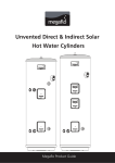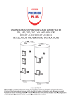
1
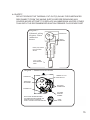
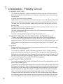
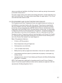
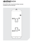
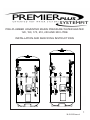
Megaflo HE
PRE-PLUMBED UNVENTED MAINS PRESSURE WATER HEATER
120, 150, 170, 210, 250 AND 300 LITRE
INSTALLATION AND SERVICING INSTRUCTIONS
1
36 00 5933 Issue 436 00 5865 Iss
36 00 5823 Issue 2
Contents
SECTION
1
INTRODUCTION............................................................................. 3
2
3
4
5
6
7
8
GENERAL REQUIREMENTS.......................................................... 4
9
FAULT FINDING & SERVICING...................................................... 27
10
DIMENSIONS & SPECIFICATIONS................................................ 30
11
GUARANTEE................................................................................... 35
12
PAGE
INSTALLATION - GENERAL........................................................... 6
INSTALLATION - DIRECT HEATING.............................................. 14
INSTALLATION - PRIMARY CIRCUIT............................................ 16
COMMISSIONING........................................................................... 20
USER INSTRUCTIONS................................................................... 23
MAINTENANCE............................................................................... 25
CONTACTS/APPROVED SPARES STOCKISTS........................... 36
........................................................................
Please read and understand these instructions before starting work.
Please leave this leaflet with the user following installation
2
Megaflo HE
1 Introduction
The Premier Plus SystemFit is a factory pre-plumbed and wired version of the Premier
Plus unvented water heater. The Premier Plus SystemFit is manufactured in the UK
from top quality materials and meets all the latest relevant safety and constructional
standards. The high grade Duplex stainless steel cylinder offers exceptional strength
and corrosion resistance which is backed by a 25 year on site parts and labour guarantee. Its performance, control system and insulation levels exceed the latest requirements of Building Regulation Part L.
The Premier Plus SystemFit unvented water heater can be fed directly from the mains
supply to the property without the need for separate feed cisterns or vent pipes. It is
supplied fitted with all its necessary inlet and safety controls for compliance with Building
Regulations. Also fitted are a primary circulating pump, automatic bypass valve, a flow
balancing valve, 2 x 2 port motorised valves, a cylinder thermostat, thermal cut-out and
wiring centre. The pump, motorised valves and thermal controls are supplied pre-wired.
A heating and domestic hot water programmer and room temperature sensor are supplied loose for installation at a convenient position within the property. An electric immersion heater is also fitted to enable the unit to be heated should the boiler be turned off.
The Premier Plus SystemFit primary circuit can be connected to a variety of gas or
oil fired boiler types, either open vented or sealed system. It is not recommended for
use with “system” boilers as these already incorporate their own circulating pump and
controls.
The Premier Plus SystemFit is supplied with a separate expansion vessel for the domestic hot water. An expansion vessel for a primary sealed circuit is also supplied loose
for installation on site.
NOTE: if using a sealed system boiler adequate provision for primary
circuit pressure relief must also be provided by means of a suitably
sized Pressure Relief Valve. The safety valves fitted to the Premier Plus
SystemFit protect the water heater only. Failure to provide adequate Primary System Pressure Relief when using a sealed system will invalidate
the boiler manufacturers warranty. Consult the boiler manufacturers
installation instructions for further advice.
3
2
General Requirements
IMPORTANT : PLEASE READ AND UNDERSTAND THESE INSTRUCTIONS BEFORE INSTALLING THE PREMIER PLUS SYSTEMFIT WATER HEATER. INCORRECT INSTALLATION MAY INVALIDATE GUARANTEE.
THE PREMIER PLUS MUST BE INSTALLED BY A COMPETENT INSTALLER IN
ACCORDANCE WITH BUILDING REGULATION G3 (ENGLAND AND WALES),
TECHNICAL STANDARD P3 (SCOTLAND) OR BUILDING REGULATION P5
(NORTHERN IRELAND).
2.1 COMPONENT CHECK LIST
Before commencing installation check that all the components for your Premier Plus SystemFit
unit are contained in the package. The following components are supplied with your Premier Plus
unit :
•
•
•
•
•
•
•
•
•
•
•
•
•
•
•
•
Factory fitted immersion heater (s) and thermal controls
Cold Water Combination Valve (comprises Pressure Reducing Valve, Strainer, Check Valve)(supplied loose)
Factory fitted Expansion core unit (comprises Expansion Valve and Check Valve)
Potable water Expansion Vessel (supplied loose)
Factory fitted Temperature/Pressure Relief Valve (set at 90oC/10bar)
Tundish
Factory fitted Indirect Thermostat and Thermal Cut-out
2 x 2-Port Motorised Valve
Primary circulating pump
Lock-shield flow balancing valve
Automatic bypass valve
Primary circuit filling loop
Primary circuit Pressure Gauge
Automatic air vent
Primary circuit expansion vessel (12 litre) (supplied loose)
CH/DHW programmer and room temperature sensor (supplied loose)
2.2 SITING THE PREMIER PLUS SYSTEMFIT
The Premier Plus SystemFit unit must be vertically floor mounted. It can be placed anywhere convenient provided the discharge pipe(s) from its safety valves can be correctly installed. Areas that
are subject to freezing must be avoided. Ensure that the floor is of sufficient strength to support
the “full” weight of the unit (refer to Dimensions Tables on pages 30 and 31 for unit weights). Pipe
runs should be kept as short as possible for maximum economy. Access to associated controls,
immersion heaters and indirect controls (Note: indirect controls housing hinges open to the left
hand side) should be possible for servicing and maintenance of the system.
4
To aid installation the Premier Plus SystemFit is provided with lifting points located in the base
and top mouldings. A floor template is also provided to aid positioning.
Megaflo HE
If you choose to install the PremierPlus SystemFit in the highest point in the property (e.g.
loft space), it is advisable to install an additional Automatic Air vent (AAV) (not suppliedavailable as spare, part number 95 605 050) above the pump to enable air to be removed
from the system. The addition of the AAV is not required if siting the cylinder in a lower
position.
2.3 WATER SUPPLY
Bear in mind that the mains water supply to the property will be supplying both the hot and
cold water requirements simultaneously. It is recommended that the maximum
water demand be assessed and the water supply be checked to ensure
this demand can be satisfactorily met.
NOTE: A high mains water pressure will not always guarantee high flow
rates.
Wherever possible the main supply pipe should be in 22mm. We suggest that the minimum supply requirements should be 1.5 bar pressure and 20 litres per minute flowrate. At
these values outlet flowrates may be poor if several outlets are used simultaneously, the
higher the available pressure and flowrate the better the system performance will be.
The Premier Plus SystemFit has an operating pressure of 3.5 bar which is controlled by
the Cold Water Combination Valve. The Cold Water Combination Valve can be connected
to a maximum mains supply pressure of 16 bar. The water supply must be of wholesome
water quality (Fluid Category 1 as defined by the Water Supply Regulations 1999).
2.4 OUTLET/TERMINAL FITTINGS (TAPS, ETC.)
The Premier Plus SystemFitcan be used in conjunction with most types of terminal fittings,
plumbing fittings and pipework. However, the rated pressures of any fittings selected
should be checked for compatibility before installation.
NOTE: Accessories, plumbing fittings and pipework should have a rated
operating pressure of at least 6 bar.
Outlets situated higher than the Premier Plus SystemFitunit will give outlet pressures
lower than that at the heater, a 10m height difference will result in a 1 bar pressure reduction at the outlet fitting.
2.5 LIMITATIONS
The Premier Plus SystemFit unvented water heater should not be used in any of the following instances:
•
•
Solid fuel boilers or any other boiler in which the energy input is not under effective thermostatic control unless additional and appropriate safety measures are installed.
Steam heating plant
•
Ascending spray type bidets or any other Class 5 back syphonage risk requiring that a Type AA, AB, AD or AG air gap be employed.
•
Water supplies that have either inadequate pressure or where the supply may be intermittent.
•
Situations where it is not possible to safely pipe away any discharge from the safety valves.
•
Areas where the water consistently contains a high proportion of solids, eg. sus
pended matter that could block the strainer, unless adequate filtration can be
ensured.
5
3
Installation - General
3.1 PIPE FITTINGS
The connection points to the heating system are in 22mm o/dia copper pipe on 120 and 150 litre
units. On units 170 litres and above the primary flow connection is 28mm, the flow connections
to central heating (CH) zones 28mm and the domestic hot water (DHW) return connection 22mm
o/dia copper pipe. The use of appropriately sized COMPRESSION FITTINGS is recommended
when connecting to the Premier Plus SystemFit pipes. Solder fittings can be used, but extreme
care must be taken to ensure the plastic coating of the unit casing is not damaged by heat. Push
fit type fittings can be used for connection to the copper pipes.
The inlet connection to the cold water combination valve is 22mm compression. The Premier
Plus SystemFit outlet fitting is suitable for connection to 22mm o/dia pipe (compression nut and
olive supplied). The outlet is also threaded 3/4” BSP male parallel should threaded pipe connections be preferred.
3.2 COLD WATER SUPPLY
A 22mm cold water supply is recommended, however, if a 15mm (1/2”) supply exists which
provides sufficient flow (see section 2.3) this may be used. More flow noise may be experienced
from small bore pipes due to the increased water velocity through them.
A stopcock or servicing valve should be incorporated into the cold water supply to enable the
Premier Plus SystemFit and its associated controls to be isolated and serviced.
3.3 COLD WATER COMBINATION VALVE (see Diagram 1)
The Cold Water Combination Valve is supplied loose, but must be plumbed in the inlet supply to
the Premier Plus SystemFit . The Cold Water Combination Valve can be sited anywhere on the
cold mains supply prior to the Premier Plus SystemFit unit. It can be located at a point where the
mains supply enters the premesis if this is more convenient.
The Cold Water Combination Valve is installed as a complete one-piece unit. The valve incorporates a factory set, non-adjustable Pressure Reducer/Strainer and a single Check Valve.
3.4 EXPANSION CORE UNIT (see Diagram 2)
Should a balanced pressure cold water supply be required to cold water outlets, such as thermostatic shower mixer valves or combination taps, the cold water balanced draw off connection
should be taken from between the Cold Water Combination Valve and the Expansion Core Unit
(see Diagram 3). Branches to cold drinking water outlets should be taken directly from
the mains supply.
3.5 POTABLE WATER EXPANSION VESSEL
The potable water Expansion Vessel (grey vessel) accommodates expansion that results from
heating the water inside the unit. The unit is pre-charged at 3.5 bar. The Expansion Vessel must be
connected between the Expansion Core Unit and the Premier Plus SystemFit (see Diagram 3) using
the connection provided on the inlet pipe and flexible hose supplied.. The location of the Expansion
Vessel should allow access to recharge the pressure as and when necessary, this can be done
6
MEGAFLO
MegafloHHE
using a normal car foot pump. It is recommended that the Expansion Vessel is adequately
supported. An Expansion Vessel wall mounting bracket is supplied for this purpose
Diagram 1 - Cold Water Combination Valve
COLD MAINS
CONNECTION
(22mm)
OUTLET
CONNECTION
(22mm)
PRESSURE
REDUCING
VALVE
HOUSING
PRESSURE
REDUCING
VALVE
CARTRIDGE (3.5 bar)
Diagram 2 - Expansion Core Unit
EXPANSION RELIEF VALVE CONNECTION
EXPANSION CORE UNIT (INCORPORATES
CHECK VALVE)
FROM COLD WATER
COMBINATION VALVE
EXPANSION RELIEF VALVE
DISCHARGE CONNECTION
EXPANSION RELIEF VALVE
TO PREMIER PLUS INLET
CONNECTION
22mm COMPRESSION
CONNECTIONS
7
8
Incoming Cold
Water Main
MCWS to Kitchen
(unbalanced cold
mains supply)
Cold Water Combination
Valve incorporating
Pressure Reducing Valve,
Strainer and Check Valve
NB Expansion Valve
tapping must be blanked
off
SC
SC
DOC
Expansion Core
Unit (combined
Expansion Relief
Valve/Check Valve)
Expansion
Vessel
DOC
Tundish
Balanced cold water
draw off
DOC
HWS supply
Discharge pipe to atmosphere
(See Section 3.9 “Discharge
Pipework“)
Premier Plus
Systemfit
Temperature/Pressure
Relief Valve
Diagram 3 - Schematic installation diagram showing Cold Water Combination
Valve, Expansion Core Unit and positioning of cold balanced draw off
DOC
KEY
MCWS Mains cold water supply
HWS Hot water service
SC
Stop Cock
DOC Drain Off Cock
Isolating/Regulating
Valves as required
Balanced HWS and
MCWS to bathrooms,
showers,cloakrooms,
etc.
Megaflo HE
3.5 DRAIN TAPS
Drain taps are fitted to both the primary system pipework and to the cold water inlet to facilitate
draining the unit or indirect heating circuit for maintenance purposes. It is recommended that
the outlet point of the drain pipe work be at least 1 metre below the level of the heater (this can
be achieved by attaching a hose pipe to the drain tap outlet spigot).
3.6 OUTLET PIPEWORK
Ideally the pipework from the Premier Plus SystemFit to the outlet fittings should be in 22mm
pipe with short runs of 15mm pipe to showers and basin taps. Small bore pipe can also be used
to suit some taps, but runs should be of minimum length. Pipe sizes may vary due to system
design.
3.7 SECONDARY CIRCULATION
If a secondary circulation system is required it is recommended that it be connected to the
Premier Plus as shown in Diagram 4 via the tee joint supplied. This is supplied capped off, the
cap must be removed before connection. Care must be taken if using a solder fitting to protect
the plastic coated surface of the Premier Plus SystemFit casing. The secondary return pipe
should be in 15mm pipe and incorporate a check valve to prevent backflow. A suitable WRAS
approved bronze circulation pump will be required. On large systems, due to the increase in
system water content, it may be necessary to fit additional expansion volume to the system by
fitting an external potable water expansion vessel to the secondary circuit. This should be done
if the capacity of the secondary circuit exceeds 10 litres.
Pipe capacities (copper)
15mm o/d = 0.13 litres per metre run (10 litres = 77m)
22mm o/d = 0.38 litres per metre run (10 litres = 26m)
28mm o/d = 0.55 litres per metre run (10 litres = 18m)
3.8 WARNINGS
i) Under no circumstances should the factory fitted Temperature/Pressure
Relief Valve be removed other than by Authorised Santon personnel. To
do so will invalidate any guarantee or claim.
ii) The Cold Water Combination Valve must be fitted to the mains water supply to the Premier Plus unit.
iii) No control or safety valves should be tampered with.
iv) The discharge pipe should not be blocked or used for any other purpose.
9
Diagram 4 - Secondary circulation connecCOLD
SUPPLY
COLD INLET
CONNECTION
CHECK
VALVE
SECONDARY
RETURN
SECONDARY
CIRCULATION
PUMP
TEE PIECE (SUPPLIED CAPPED OFF,
REMOVE CAP BEFORE CONNECTION)
10
Megaflo HE
3.9 DISCHARGE PIPEWORK
It is a requirement of Building Regulations that any discharge from an unvented system is conveyed
to where it is visible, but will not cause danger to persons in or about the building. The tundish
and discharge pipes should be fitted in accordance with the requirements and guidance notes
of Building Regulations. Building Regulation G3 Requirements and Guidance section 3.9 are
reproduced in the following sections.
Information Sheet No. 33 available from the British Board of Agrement gives further advice on
discharge pipe installation. For discharge pipe arrangements not covered by G3 Guidance or
BBA Info Sheet No.33 advice should be sought from either your local Building Control Officer or
Heatrae Sadia.
The discharge pipework supplied fitted to the Premier Plus Systemfit is for the Premier Plus only.
A sealed system boiler installation will require its own, separate discharge pipe arrangement (refer
to the boiler manufacturers instructions for the correct installation of this).
G3 REQUIREMENT
“...there shall be precautions...to ensure that the hot water discharged from safety devices is
safely conveyed to where it is visible but will not cause danger to persons in or about the building.”
G3 GUIDANCE SECTION 3.9
The discharge pipe (D1) from the vessel up to and including the tundish is generally supplied by
the manufacturer of the hot water storage system. Where otherwise, the installation should include
the discharge pipe(s) (D1) from the safety device(s). In either case the tundish should be vertical,
located in the same space as the unvented hot water storage system and be fitted as close as
possible and within 500mm of the safety device e.g. the temperature relief valve.
The discharge pipe (D2) from the tundish should terminate in a safe place where there is no risk
to persons in the vicinity of the discharge, preferably be of metal and:
a. be at least one pipe size larger than the nominal outlet size of the safety device unless its
total equivalent hydraulic resistance exceeds that of a straight pipe 9m long i.e. discharge pipes
between 9m and 18m equivalent resistance length should be at least two sizes larger than the
nominal outlet size of the safety device, between 18 and 27m at least 3 sizes larger , and so on.
Bends must be taken into account in calculating the flow resistance. Refer to Diagram 5, Table 1
and the worked example.
An alternative approach for sizing discharge pipes would be to follow BS 6700:1987 Specification
for design, installation, testing and maintenance of services supplying water for domestic use within
buildings and their curtilages, Appendix E, section E2 and table 21.
b. have a vertical section of pipe at least 300mm long below the tundish before any elbows or
bends in the pipework.
c. be installed with a continuous fall.
d. have discharges visible at both the tundish and the final point of discharge, but where this is not
possible or is practically difficult there should be clear visibility at one or other of these locations.
11
Examples of acceptable discharge arrangements are:
i. ideally below a fixed grating and above the water seal in a` trapped gully.
ii. downward discharges at low level; i.e. up to 100mm above external surfaces such as car parks,
hard standings, grassed areas etc. are acceptable providing that where children may play or
otherwise come into contact with discharges a wire cage or similar guard is positioned to prevent
contact, whilst maintaining visibility.
iii. discharges at high level; e.g. into a metal hopper and metal down pipe with the end of the
discharge pipe clearly visible (tundish visible or not) or onto a roof capable of withstanding high
temperature discharges of water and 3m from any plastics guttering system that would collect
such discharges (tundish visible).
iv. where a single pipe serves a number of discharges, such as in blocks of flats, the number
served should be limited to not more than 6 systems so that any instalation discharging can be
traced reasonably easily. The single common discharge pipe should be at least one pipe size larger
than the largest individual discharge pipe (D2) to be connected. If unvented hot water storage
systems are installed where discharges from safety devices may not be apparent i.e. in dwellings
occupied by blind, infirm or disabled people, consideration should be given to the installation of
an electronically operated device to warn when discharge takes place.
Note: The discharge will consist of scalding water and steam. Asphalt, roofing felt and non-metallic
rainwater goods may be damaged by such discharges.
Worked example of discharge pipe sizing
The example below is for a G1/2 temperature relief valve with a discharge pipe (D2) having 4
No. elbows and length of 7m from the tundish to the point of discharge.
From Table 1:
Maximum resistance allowed for a straight length of 22mm copper discharge pipe (D2) from a
G1/2 temperature relief valve is 9.0m.
Subtract the resistance for 4 No. 22mm elbows at 0.8m each = 3.2m
Therefore the permitted length equates to: 5.8m
5.8m is less than the actual length of 7m therefore calculate the next largest size.
Maximum resistance allowed for a straight length of 28mm pipe (D2) from a G1/2 temperature
relief valve equates to 18m.
Subtract the resistance of 4 No. 28mm elbows at 1.0m each = 4.0m
Therefore the maximum permitted length equates to: 14m
As the actual length is 7m, a 28mm (D2) copper pipe will be satisfactory.
12
Megaflo HE
Table 1 - Sizing of copper discharge pipe (D2) for common T&P relief valve sizes
VALVE OUTLET
SIZE
MINIMUM SIZE OF
DISCHARGE PIPE D1
MINIMUM SIZE OF
DISCHARGE PIPE D2
FROM TUNDISH
MAXIMUM RESISTANCE
ALLOWED, EXPRESSED
AS A LENTGH OF
STRAIGHT PIPE (I.E. NO
ELBOWS OR BENDS
RESISTANCE CREATED BY
EACH ELBOW OR BEND
G 1/2
15MM
G 3/4
22MM
G1
28MM
22mm
28mm
35mm
28mm
35mm
42mm
35mm
42mm
54mm
UP TO 9M
UP TO 18M
UP TO 27M
UP TO 9M
UP TO 18M
UP TO 27M
UP TO 9M
UP TO 18M
UP TO 27M
0.8M
1.0M
1.4M
1.0M
1.4M
1.7M
1.4M
1.7M
2.3M
Safety device
(e.g. Temperature
relief valve)
Metal discharge pipe (D1) from
Temperature relief valve to tundish
500mm maximum
Tundish
300mm
minimum
Discharge pipe (D2) from tundish,
with continuous fall. See Building
Regulation G3 section 3.9d i-iv,
Table 4 and worked example
Discharge below
fixed grating
(Building Regulation
G3 section 3.9d gives
alternative points
of discharge)
Fixed grating
Trapped
gully
13
4
Installation - Direct Heating
4.1 IMMERSION HEATER(S)
The Premier Plus SystemFit is supplied with a factory fitted immersion heater which can be
used as an alternative heat source should the boiler supply need to be isolated from the unit.
The immersion heater is located within the indirect controls housing. The immersion heater is
rated 3kW at 240V (2.7kW at 230V). 210 litre models and above are supplied with a second
blanked off boss which can be used for the connection of a second immersion heater should
this be required.
To remove the blanking plug:
Open the cover to the upper immersion heater boss. The cover is secured by a cross-headed
screw. Unscrew brass backnut using the key spanner provided with the unit. Remove the
blanking plate and sealing gasket from the boss.
Fitting the additional immersion heater (where required order Part No. 95 970 510):
Insert the immersion heater and sealing gasket into the boss. Ensure that the sealing gasket is
not displaced when inserting. It may be helpful to support the immersion heater using a round
bladed screwdriver inserted into one of the thermostat pockets. Hand tighten the brass backnut.
Secure the immersion heater in position by tightening with the key spanner provided.
4.2 WIRING (see Diagram 6)
All electrical wiring should be carried out by a competent electrician and be in accordance with
the latest I.E.E. Wiring Regulations. Each circuit must be protected by a suitable fuse
and double pole isolating switch with a contact separation of at least 3mm in
both poles.
The immersion heater(s) should be wired in accordance with Diagram 6. The Live and Neutral
conductors should be connected directly to the combined thermostat/thermal cut-out to the terminals marked A and B. The immersion heaters MUST be earthed. The supply cable should
be 1.5mm2 3 core HOFR sheathed and must be routed through either the cable grip provided
(lower housing) or the cable gland provided (upper housing 210 litre units and above only) with
the outer sheath of the cable firmly secured by tightening either the top bar of the cable grip or
the screws on the cable gland. Replace the housing cover(s) before operating. On the upper
housing (210 litre and above only) ensure that the threaded edge clip is in position to provide a
suitable thread for the cover screw.
DO NOT operate the immersion heater(s) until the Premier Plus SystemFit has been filled
with water.
4.3 OPERATION
It is recommended that the immersion heater thermostats are set to between position 4 and 5
(60o - 65oC), however they can be set between 1 and 5 (10o and 70oC). The thermostat incorporates a thermal cut-out that will switch off the immersion heater in the event of a thermostat
failure. The thermal cut-out reset button position is indicated on Diagram 7. DO NOT bypass
the thermal cut-out in any circumstances.
14
Megaflo HE
4.4 SAFETY
DO NOT BYPASS THE THERMAL CUT-OUT(S) IN ANY CIRCUMSTANCES
DISCONNECT FROM THE MAINS SUPPLY BEFORE REMOVING ANY
COVERS NEVER ATTEMPT TO REPLACE AN IMMERSION HEATER OTHER
THAN WITH THE RECOMMENDED SANTON PREMIER PLUS SPARE PART
Diagram 6 Schematic wiring
diagram - Direct
immersion
heaters
THERMOSTAT
EARTH
TERMINAL
FUSED (13A) DOUBLE
POLE ISOLATING
SWITCH
1.5mm2 3 CORE
HOFR SHEATHED
CABLE
Diagram 7 - Immersion heater details
THERMOSTAT
THERMAL CUT-OUT
RESET BUTTON
THERMOSTAT
ADJUSTMENT
ELECTRICAL
TERMINATIONS
EARTHING TAG
NOTE: EARTH LINK WIRE BETWEEN
CUSTOMER EARTHING TERMINAL AND
EARTHING TAG NOT SHOWN FOR
CLARITY. THIS MUST NOT BE REMOVED.
CUSTOMER
EARTHING
TERMINAL
CABLE
GLAND
15
5
Installation - Primary Circuit
5.1 BOILER SELECTION
The Premier Plus SystemFit models are suitable for use with most gas or oil fired or electric
boilers compatible with unvented systems i.e. fitted with a temperature control thermostat and
thermal cut-out.
If in doubt consult the boiler manufacturer.
Solid fuel boilers or any other boiler in which the energy input is not under effective thermostatic
control unless additional and appropriate safety measures are installed should NOT be used.
The boiler used can either be a sealed system or open vented type, maximum primary circuit
pressure 3 bar.
The primary flow from the boiler MUST be pumped. Gravity circulation will not work due to the
special design of the primary heat exchanger.
The boiler flow temperature should usually be set to 82oC (maximum flow temperature to
primary heat exchanger 90oC).
The boiler cannot be vented through the Premier Plus SystemFit unit.
5.2 INDIRECT THERMAL CUT-OUT AND 2-PORT MOTORISED VALVE
To comply with Building Regulations and to prevent the Premier Plus from overheating the
2-Port motorised valve supplied fitted to the primary flow to the indirect coil MUST NOT be
removed or bypassed. This valve is factory wired in series with the indirect thermal cut-out such
that the primary flow to the heating coil is interupted should the Premier Plus SystemFit unit
overheat.
5.3 WIRING
All electrical wiring should be carried out by a competent electrician and be in accordance with
the latest I.E.E. Wiring Regulations.
The Premier Plus SystemFit Indirect Thermostat and Thermal Cut-out, primary circulating
pump and motorised valves are factory pre-wired. Further wiring will be required between the
Wiring Centre, the Programmer, Room Temperature Sensor and the boiler (see Diagram 9). Additional controls and wiring will be required if a second CH zone is to be fitted to the instalation.
The Indirect Thermal Cut-out MUST NOT be bypassed.
5.4 HEATING SYSTEM CONTROLS
The controls provided with the Premier Plus SystemFit will ensure the safe operation of the unit
within a central heating system.
Connection to the various system components is made via the Wiring Centre fitted to the front of
the Premier Plus SystemFit . Refer to Diagram 9 and the terminal identification labels within the
Wiring Centre to aid in connecting the various external system components such as the mains
supply, programmer and boiler. The wiring to the external components is made using flexible
cable, this should be secured using the integral cable grips located in the Wiring Centre.
Provision is made for the connection of a second CH zone (connection pipe supplied blanked
off). Additional controls will be necessary to control the operation of the second CH zone, usually a second 28mm CH zone valve and a programmable room thermostat. Connection termi-
16
Megaflo HE
nals are provided and identified in the Wiring Centre to enable any wiring to be connected
to the same central position.
The mains supply must be via a double pole isolating switch with a contact separation of at
least 3mm in both poles. The supply must be fused 3Amp. A supply cable of 1.0 to 1.5mm2
cross sectional area should be used.
5.5 PROGRAMMER AND ROOM TEMPERATURE SENSOR
The Programmer and Room Temperature Sensor are supplied loose such that they can
be installed at a convenient location within the property. These items are supplied with
their own Installation and User Instruction leaflet which should be referred to for details
of mounting, wiring and programming. NOTE the Room Sensor is wired directly to the
Programmer not to the Wiring Centre. The Room Sensor must be used, it is not possible
to integrate a standard room thermostat with the Programmer. Temperature setting of the
room temperature is also done at the Programmer, there is no adjustment at the Room
Temperature Sensor. Temperature setting of the stored water in the Premier Plus SystemFit is done at the indirect thermostat housed within the Indirect Terminal Housing on the
front of the Premier Plus SystemFit unit (see Diagram 8).
Basic Programmer features:
•
•
•
•
•
•
•
24 Hour or 5/2 Day operation
Room temperature setting at Programmer
Set temperature over-ride facility
1 Hour hot water boost facility
Battery back up retains programmed information in the event of a power interuption
Low temperature set back option for periods when the property is unoccupied, eg. holiday periods
Independent time control of Central Heating and Domestic Hot Water (Building Regu
lation Part L1 compliant)
NOTE: The Programmer supplied will only provide control for one CH zone. Should a
second CH zone be required additional controls will be needed (not supplied) to fulfill the
requirements of Building Regulation Part L1.
17
Diagram 8 - Indirect controls housing
INDIRECT THERMAL
CUT-OUT RESET
BUTTON
INDIRECT
THERMAL
CUT-OUT
THERMOSTAT
ADJUSTMENT
INDIRECT
THERMOSTAT
CABLE CLAMPS
TERMINAL BLOCK
NOTE:
THE HOUSING COVER AND ELEMENT ASSEMBLY HAVE BEEN REMOVED FROM
THIS VIEW FOR CLARITY
18
19
5
6
BROWN
BLUE
GREY
ORANGE
WHITE
GREEN/YELLOW
DOMESTIC HOT WATER
HEATING
LIVE
NEUTRAL
EARTH
L
N
N
O
GY
3
HEATING ZONE 1VALVE
(SUPPLIED FITTED)
Br Bl G
N
2
W
2
4
N
6
7
2
O
8
3
N
Br Bl G
O
GY
(DHW)
ZONE VALVE
(SUPPLIED FITTED)
GY
W
BOILER
L N
L N
PUMP
(SUPPLIED FITTED)
N
N
9 10 11 12 13 14 15 16
HEATING ZONE 2 VALVE
(NOT SUPPLIED)
Br Bl G
5
1
INDIRECT
THERMAL CONTROLS
(SUPPLIED FITTED)
Megaflo HE
NOTES
1. ALL EARTH CONNECTIONS MUST BE LINKED BACK TO THE EARTH TERMINALS IN THE WIRING CENTRE
2. ALL NEUTRAL CONNECTIONS MUST BE LINKED BACK TO THE NEUTRAL TERMINALS IN THE WIRING CENTRE
3. ASSUMES BASIC BOILER
4. THE 22MM MOTORISED VALVES DO NOT HAVE A WHITE WIRE
5. THE ABOVE DIAGRAM IS FOR GUIDANCE ONLY, SANTON ACCEPT NO LIABILITY FOR ANY LOSS OR DAMAGE ARISING FROM
ANY ERRORS OR OMISSIONS THAT MAY BE INADVERTENTLY CONTAINED WITHIN THIS DIAGRAM. THE VARIOUS EQUIPMENT
MANUFACTURERS SHOULD BE CONSULTED TO CONFIRM THE CORRECT OPERATION OF THEIR PRODUCTS WITHIN THE SYSTEM
KEY
Br
Bl
G
O
W
GY
DHW
HTG
L
N
FUSED (3 AMP)
MAINS SUPPLY
1
1
PROGRAMMABLE
ROOM THERMOSTAT
FOR ZONE 2
(NOT SUPPLIED)
ROOM SENSOR
(SUPPLIED)
4 3
DHW
ON
N.B. A DOUBLE POLE ISOLATING
SWITCH MUST BE INSTALLED IN
THE MAINS SUPPLY
WIRING CENTRE
(SUPPLIED FITTED)
N
L N
HTG
ON
PROGRAMMER - HEATING ZONE 1
& DOMESTIC HOT WATER
(SUPPLIED)
Diagram 9 - Schematic wiring diagram - indirect circuit
6
Commissioning
6.1 FILLING AND FLUSHING THE PREMIER PLUS SYSTEMFIT
It is possible for compression fittings to become loose in transit due to transport vibration.
Ensure that all fittings and immersion heaters are correctly fitted and tightened. An immersion
heater key spanner is provided to aid in tightening the immersion heater(s).
i)
Open a hot tap furthest from the Premier Plus SystemFit .
ii) Open the isolating valve to the Premier Plus SystemFit installation. Open the mains stop cock to fill the unit. When water issues from the tap, allow to run for a few minutes to thoroughly flush through any residue, dirt or swarf, then close tap.
iii)
Open successive hot taps and any cold outlet supplied by a balanced take off to purge any air from the system.
iv)
Check all connections for leaks and rectify as necessary.
v)
The Strainer housed within the Cold Water Combination Valve should be cleaned to remove any debris that may have been flushed through the main supply pipe. Refer to Section 8.3 for instructions on how to do this.
6.2 CHECK THE OPERATION OF THE SAFETY
VALVES
i)
Slowly manually open, for a few seconds, the Temperature and Pressure Relief Valve situated on the Premier Plus unit (see Diagram 11). Check water discharged runs freely away through the tundish and discharge pipework. Close valve, ensure water flow stops and valve reseats correctly.
ii)
Repeat for the Expansion Valve situated on the Expansion Core Unit (see Diagram 11).
6.3 DIRECT HEATING
Switch on the electrical supply to the immersion heater(s) and allow the unit to heat up. Check
that the thermostat operates correctly. A storage temperature of approx. 60oC is recommended
(between graduations 4 and 5 on the thermostat). If necessary the temperature can be adjusted
by inserting a flat bladed screwdriver in the adjustment knob on top of the immersion heater
thermostat and rotating (see Diagram 7). The adjustment range 1 to 5 represents a temperature
range of between 10o and 70oC.
Check that no water is discharged from either the Expansion Valve or Temperature and Pressure Relief Valve during the heating cycle.
6.4 INDIRECT (PRIMARY) CIRCUIT
Fill the indirect (primary) circuit following the boiler manufacturer’s commissioning instructions.
To ensure the primary heating system is correctly filled the 2-port motorised valves should be
manually opened by moving the lever on the motor housings to the MAN OPEN setting. When
the primary circuit is full return the levers to the AUTO position. Vent any trapped air. Check the
primary system for leaks and rectify as necessary. Flush the primary system in accordance with
the boiler manufacturers instructions and add a suitable inhibitor when re-filling.
20
Megaflo HE
Switch on the electrical supply to the Premier Plus SystemFit indirect controls and the
boiler. Programme the Premier Plus SystemFit controller as detailed in the Fitting and User
Instruction leaflet supplied with the controller. Set the controller for Hot Water operation
only (the +1HR ON Hot Water over-ride button can be used if the time is during a Hot Water OFF period). Check that the Heating 2-Port motorised valve is closed and that the Hot
Water 2-Port motorised valve opens. The pump should run and the boiler fire (tap symbol
appears in controller display). The primary flow to the Premier Plus SystemFit should
become hot, if it does not check for a wiring or piping error. Allow the Premier Plus unit
to heat up and check that the Hot Water thermostat and 2-Port motorised valve operate
correctly. A storage temperature of approx. 60oC is recommended (approx. graduation 4
on the indirect thermostat). If necessary the temperature can be adjusted by inserting a flat
bladed screwdriver in the adjustment knob (located on the front of the thermostat mounting
bracket see Diagram 8) and rotating. The minimum thermostat setting is 10oC. The adjustment range 1 to 5 represents a temperature range of 30o to 70oC.
Select the Heating only function on the controller. NOTE: The room temperature is set at
the controller, no adjustment is possible at the Room Sensor unit. Check that the Heating
2-Port motorised valve opens and that the Hot Water 2-Port motorised valve is closed. The
pump should run and the boiler fire (a flame symbol appears in the controller display). The
primary flow to the Premier Plus SystemFit and the radiator circuit should become hot, if it
does not check for a wiring or piping error.
If a second CH zone is fitted adjust the programmable room thermostat so that it is calling
for heat. Check that the second CH zone valve opens. The pump should run and the boiler
fire. The primary flow to the second CH zone should become hot, if it does not check for a
wiring or piping error.
Select the Heating and Hot Water control function on the controller. Check that the Heating
2-Port motorised valve and the Hot Water 2-Port motorised valve open. NOTE: it may be
necessary to cool the Premier Plus SystemFit down to allow the indirect thermostat to call
for heat, it may also be necessary to increase the required room temperature setting if the
room temperature has already reached that programmed. The pump should run and the
boiler fire (both a tap symbol and a flame symbol should appear in the controller display).
The primary flow to the Premier Plus SystemFit and the radiator circuit should become hot,
if it does not check for a wiring or piping error.
When the Heating and Hot Water temperatures are reached the 2-Port motorised valves
should close, the pump stop running and the boiler stop firing. NOTE: if a pump over-run
boiler is fitted the pump may continue to run for a short time after the boiler has shut down.
Check that no water is discharged from either the Expansion Valve or Temperature and
Pressure Relief Valve during the heating cycle. (Cont. over page)
21
If the user temperatures or On and Off times have been adjusted for commissioning purposes
the controller should be reset to the desired settings. The operation of the controller should be
demonstrated to the user and the Controller Installation and User Instructions left with them for
future reference.
6.5 AUTOMATIC SYSTEM BY-PASS
An automatic differential bypass valve is fitted to the Premier Plus SystemFit. This has been factory set to an optimum position for most domestic heating systems. However, in some systems it
may require further adjustment. To do this:
Loosen the brass locking screw on the top of the adjustment cap of the bypass valve. Turn the
adjustment knob fully clockwise so that the number 5 coincides with the indicator arrow on the
body of the valve.
Turn on the system and set the controller to Heating only. Balance the system in the normal
manner.
With the boiler firing and the pump running, slowly turn the adjustment knob anti-clockwise until
hot water can be felt on the outlet side of the bypass valve. Turn the adjustment knob clockwise
by half a turn. Lock in position by tightening the brass locking screw.
6.5 BENCHMARKTM LOG BOOK
On completion of the installation and commissioning procedures detailed in this manual the
Benchmark TM “Installation, Commissioning and Service Record Log Book” should be completed
and signed off by the competent installer or commissioning engineer in the relevant sections.
The various system features, location of system controls, user instructions and what to do in
the event of a system failure should be explained to the customer. The customer should then
countersign the BenchmarkTM log book to accept completion.
The log book should be left with the customer along with these instructions. The log book
includes sections that should be filled in when any subsequent service or maintenance operation
is carried out on the Premier Plus SystemFit.
22
User Instructions
7.1 WARNINGS
Megaflo HE
7
IF WATER ISSUES FROM THE TEMPERATURE/PRESSURE RELIEF
VALVE ON THE PREMIER PLUS UNIT SWITCH OFF ELECTRICAL SUPPLY TO THE IMMERSION HEATER(S) OR SHUT DOWN THE BOILER.
DO NOT TURN OFF THE WATER SUPPLY. CONTACT A COMPETENT INSTALLER FOR UNVENTED WATER HEATERS TO CHECK THE SYSTEM.
DO NOT TAMPER WITH ANY OF THE SAFETY VALVES FITTED TO THE
PREMIER PLUS SYSTEM, IF A FAULT IS SUSPECTED CONTACT A COMPETENT INSTALLER.
7.2 TEMPERATURE CONTROL
IMMERSION HEATER(S)
A combined thermostat and thermal cut-out is provided for each immersion heater. The
thermostat is factory set to give a water storage temperature of approx. 60oC, however
it can be set to control between 10oC and 70oC. This will usually have been done during
installation. Adjustments can only be made by opening the terminal cover(s), DO NOT
remove the cover(s) without first switching off the electrical supply. The
temperature adjustment is made by inserting a flat bladed screwdriver in the slot in the disc
on top of the thermostat and rotating (see Diagram 7).
If in any doubt consult a competent electrician.
HEATING BY BOILER
The Premier Plus SystemFit is fitted with an Indirect Thermostat which controls a 2 Port
motorised valve and hence the temperature of the water in the Premier Plus SystemFit
unit. The thermostat is factory set to give a water storage temperature of approx. 60oC,
however it can be set to control between 10oC and 70oC, this will usually have been
done during installation. Adjustments can only be made by opening the terminal cover.
DO NOT remove the cover without first switching off the electrical supply.
Temperature adjustment is made by inserting a flat bladed screwdriver in the adjustment
knob located on the front of the thermostat mounting bracket (see Diagram 8) and rotating.
At the minimum position the temperature will be approx. 10oC. The adjustment range 1 to 5
represents a temperature range of 30o to 70oC
If in any doubt consult a competent electrician.
DO NOT bypass the thermal cut-outs in any circumstances.
The space heating control temperature and the operating times for Heating and Hot Water
are set using the remotely mounted Controller. The optimum temperatures and times
will have been set during commissioning. Should the temperatures or timings need to be
altered refer to the Installation and User Instructions leaflet supplied with the Controller
for the method of adjustment. If a second CH zone is fitted this will be controlled by its
own programmable room thermostat. Refer to the manufacturers Installation and User
instructions supplied with the programmable room thermostat for the method of setting and
adjustment of heating times and temperatures.
23
7.3 FLOW PERFORMANCE
When initially opening hot outlets a small surge in flow may be noticed as pressures stabilise.
This is quite normal with unvented systems and does not indicate a fault.
In some areas a cloudiness may be noticed in the hot water. This is due to aeration of the water,
is quite normal and will quickly clear.
7.4 OPERATIONAL FAULTS
Operational faults and their possible causes are detailed in Section 9.3. It is recommended that
faults should be checked by a competent installer.
24
Maintenance
8.1 MAINTENANCE REQUIREMENTS
Megaflo HE
8
To ensure the continued optimum performance of the Premier Plus SystemFit it should be
regularly maintained. This is of particular importance in hard water areas or where the water supply contains particulate matter. Maintenance should be carried out by a competent
person and any replacement parts used should be authorised Santon Premier Plus spare
parts. It is recommended that maintenance is carried out every 12 months and includes the
checks detailed in 8.2 and 8.3 below.
In hard water areas consideration should be given to periodically descaling the immersion heater elements. To do this the Premier Plus unit will need to be drained, 8.4 and 8.5
below detail how to drain the unit and remove the immersion heater(s).
8.2 CHECK OPERATION OF SAFETY VALVES
Slowly open the Temperature and Pressure Relief Valve by twisting its cap for a few seconds. Check water is discharged and that it flows freely through the tundish and discharge
pipework. Check valve reseats correctly when released.
NOTE : The water discharged may be very hot.
Repeat the procedure for the Expansion Valve (located on the Expansion Valve Core Unit).
8.3 CLEAN THE STRAINER
The strainer is incorporated within the Pressure Reducing Valve housing of the Cold Water
Combination Valve (see Diagram 10). To inspect and clean the strainer:
i) Turn off the isolating valve to the Premier Plus SystemFit.
ii) Open the lowest hot tap in the system to relieve the system pressure
iii) Unscrew the Pressure Reducing Valve Cartridge from the Pressure Reducing Valve Housing.
iv) Pull the Pressure Reducing Valve cartridge from the valve assembly. The strainer will be withdrawn with the cartridge.
v) Wash any particulate matter from the strainer under clean running water.
vi) Screw the Pressure Reducing Valve cartridge into the Pressure Reducing Valve Housing ensuring the seal is correctly fitted. DO NOT use any other type of sealant.
ix) Close hot tap, turn on isolating valve. Check for leaks.
25
8.4 DRAINING THE PREMIER PLUS UNIT
Switch off the electrical supply to the immersion heater(s) and/or shut down the boiler.
Turn off the mains water supply to the Premier Plus unit. Attach a hosepipe to the drain cock
having sufficient length to take water to a suitable discharge point below the level of the unit, at
least one metre below the unit is recommended. Open hot water tap nearest to the Premier Plus
to relieve the system pressure. Open drain cock. If water fails to drain from the Premier Plus
vent the unit by manually opening the Temperature/Pressure Relief Valve.
8.5 DESCALING IMMERSION HEATER(S)
Open the cover(s) to the immersion heater housing(s) and disconnect wiring from immersion
heater(s). Remove the thermostat by carefully pulling outwards from the immersion heater. Unscrew immersion heater backnut(s) and remove immersion heater from the unit. A key spanner
is supplied with the Premier Plus SystemFit unit for easy removal/tightening of the immersion
heater(s). Over time the immersion heater gasket may become stuck to the mating surface. To
break the seal insert a round bladed screwdriver into one of the pockets on the immersion heater
and gently lever up and down.
Carefully remove any scale from the surface of the element(s). DO NOT use a sharp implement
as damage to the element surface could be caused. Ensure sealing surfaces are clean and seals
are undamaged, if in doubt fit a new gasket.
Replace immersion heater(s) ensuring the lower (right angled) element hangs vertically downwards
towards the base of the unit. It may be helpful to support the immersion heater using a round bladed
screwdriver inserted into one of the thermostat pockets whilst the backnut is tightened. Replace
the thermostat(s) by carefully plugging the two male spade terminations on the underside of the
thermostat head into the corresponding terminations on the element.
Rewire the immersion heater(s) in accordance with Diagram 6. Close and secure terminal
cover(s).
8.6 CHECK EXPANSION VESSEL CHARGE PRESSURE
Remove the dust cap on top of the vessel. Check the charge pressure using a tyre pressure gauge.
The pressure (with system de-pressurised) should be 3.5 bar. If it is lower than the required setting it should be re-charged using a tyre pump (Schrader valve type). DO NOT OVER CHARGE.
Re-check the pressure and when correct replace the dust cap.
8.7 REFILLING SYSTEM
DO NOT switch on the immersion heater(s) or boiler until the system has been completely
refilled.
Close the drain tap. With hot tap open, turn on mains water supply. When water flows from the
hot tap allow to flow for a short while to purge air and to flush through any disturbed particles.
Close hot tap and then open successive hot taps in system to purge any air. The electrical supply can now be switched on.
8.8 BENCHMARKTM LOG BOOK
26
On completion of any maintenance or service of the Premier Plus the BenchmarkTM “Installation,
Commissioning and Service Record Log Book” should be filled in to record the actions taken
and the date the work was undertaken.
Megaflo HE
9 Fault Finding & Servicing
9.1 IMPORTANT
i) Servicing should only be carried by authorised Santon Service Engineers or Agents or by competent installers in the installation and maintenance of unvented water
heating systems.
ii) Any spare parts used MUST be authorised Santon parts.
iii) Disconnect the electrical supply before removing any electrical equipment covers.
iv) NEVER bypass any thermal controls or operate system without the necessary safety valves.
v) Water contained in the Premier Plus SystemFit unit may be very hot, especially
following a thermal control failure. Caution must be taken when drawing water from the unit.
9.2 SPARE PARTS
A full range of spare parts are available for the Premier Plus SystemFit range. Refer to the
Technical Data label on the unit to identify the model installed and ensure the correct part
is ordered.
Description
Immersion heater (lower)
Immersion heater (upper)
Immersion heater gasket
Immersion heater backnut
Immersion heater key
Immersion heater blanking plug
Tundish Expansion relief valve cartridge - 6bar
Cold water combination valve body Expansion Core housing (incorporating Check Valve)
Pressure reducing valve cartridge - 3.5 bar
Cold Water Combination Valve complete
Temperature/Pressure Relief Valve
Set of compression nuts and olives
Combined thermostat/thermal cut-out for immersion heater
Terminal cover upper (210 litre units and above)
2 Port motorised valve (22mm connections)
Indirect thermostat
Indirect thermal cut-out
Terminal cover (lower)
4 way terminal block
Wiring Centre
TP9 Programmer
TP9 Room temperature sensor
Automatic bypass valve (straight pattern) Circulating pump
2 Port motorised valve (28mm connections)
Part no.
95 606 946
95 606 947
95 611 822
95 607 869
95 607 861
95 605 881
95 605 838
95 605 864
95 605 030
95 605 872
95 605 029
95 605 022
95 605 810
95 607 838
95 612 599
95 607 836
95 605 819
95 612 697
95 612 698
95 607 837
95 607 902
95 612 702
95 607 903
95 607 904
95 605 882
95 612 676
95 605 884
27
Diagram 10 - Exploded view of the Cold Water Combination Valve
Valve Body
Spare Part No.
95 605 030
Check Valve
Housing
Spare Part No.
95 605 028
Pressure Reducing
Valve Housing
Spare Part No.
95 605 027
Pressure Reducing
Valve Cartridge
Spare Part No.
95 605 029
Housing Securing
Screws (4 off)
Strainer Mesh
Cold Water Combination Valve Complete
Spare Part No. 95 605 022
9.3 FAULT FINDING
The Fault Finding chart overleaf (Table 2) will enable operational faults to be identified and their
possible causes rectified. Any work carried out on the Premier Plus SystemFit unvented water
heater and its associated controls MUST be carried out by a competent installer for unvented water
heating systems. In case of doubt contact the Santon Service Department (see Section 12).
28
FAULT
No hot water flow
Water from hot taps is
cold
POSSIBLE CAUSE
1. Mains supply off
2. Strainer blocked
3. Cold Water Combination
Valve incorrectly fitted
1. DIRECT immersion
heater not switched on
2. DIRECT immersion
heater thermal cut-out has
operated
3. INDIRECT programmer
set to Central Heating only
4. INDIRECT boiler not
working
5. INDIRECT thermal cutout has operated
6. INDIRECT motorised
valve not connected
correctly
Water discharges
from Expansion Relief
Valve
1. INTERMITTENTLY
Expansion vessel charge
pressure has reduced below
3.5 bar
2. CONTINUALLY
a. Cold Water Combination
Valve Pressure Reducer not
working correctly
b. Expansion Valve seat
damaged.
Water discharges from
T&P Relief Valve
1. Thermal control failure
NOTE water will be very hot
"Milky" water
Oxygenated water
REMEDY
1. Check and open stop cock
2. Turn off water supply.
Remove strainer and clean (see
Section 8.3)
3. Check and refit as required
1. Check and switch on
Megaflo HE
Table 2 - Fault Finding CHART
2. Check. Reset by pushing
button. (See Diagram 7)
3. Check. Set to a Domestic
Hot Water programme
4. Check boiler operation. If fault
is suspected consult boiler
manufacturer's instructions
5. Check. Reset by pushing
button on cut-out. Check
operation of indirect thermostat
6. Check wiring and/or plumbing
connections to motorised valve
(see Diagram 9)
1. See Section 7.5 for recharging procedure
a. Check pressure from Cold
Water Combination Valve. If
greater than 3 bar replace
Pressure Reducer cartridge
b. Remove Expansion Valve
cartridge. Check condition of
seat. If necessary fit new
Expansion Valve cartridge.
1. Switch off power to
immersion heater(s) and shut
down boiler. DO NOT turn off
water supply. When discharge
stops check all thermal
controls, replace if faulty.
Water from a pressurised
system releases oxygen
bubbles when flowing. The
milkiness will disappear after a
short while.
29
10 Dimensions & Specifications
Diagram 11a
FILLING LOOP
CONNECTIONS
(HOSE REMOVED
FOR CLARITY)
Ø550
PRIMARY
FLOW
OUTLET
COLD INLET
TEMPERATURE
& PRESSURE
RELIEF VALVE
AIR BLEED
VALVE
PUMP
GATE VALVE
(2 OFF)
DIM A
PRESSURE
GAUGE
DIM C
1028
DIM B
BYPASS VALVE
2 PORT
MOTORISED
VALVE (2 OFF)
418
414
DRAIN VALVE
(PRIMARY
CIRCUIT)
250
PRIMARY
RETURN
120B PUMP IS HIGHER THAN THE TOP OF THE
CYLINDER
30
WIRING CENTRE
FLOW TO RAD
CIRCUIT
EXPANSION VESSEL
CONNECTION
DRAIN VALVE
(CYLINDER)
285
Dashed line denotes minimum space
required for installation
NOTE: Minimum distance for centre
Dashed
minimum space
line of unit
to rearline
walldenotes
is 284mm.
required for installation
NOTE: Minimum distance for centre
line of unit to rear wall is 284mm.
393
288
380
Megaflo HE
Diagram 11b
DASHED LINE DENOTES MINIMUM SPACE REQUIREMENT
*Top of pump extends 95mm above this height
NOMINAL DIMENSION (mm)
A
B
C
935*
402
742
SIZE
TYPE
120
B
150
B
1119
585
170
B
1245
705
210
B
1503
975
250
B
1755
300
B
2069
UNIT WEIGHT (KG)
EMPTY
FULL
34
183
940
42
211
1050
45
240
1310
51
262
1175
1505
58
309
1475
1812
68
368
NOTE
Coil heating performance based on a primary flow rate of 15 l/min at 80o C with flow
to water heater coil heat exchanger only. Heating times may be reduced if space
heating requirement is simultaneous with water heating requirement or boiler output
is lower than potential coil output rating.
Temperature rise is from 15o C to 60o C.
Recovery is based on reheating 70% of the nominal capacity
31
OUTLINE SPECIFICATIONS
Maximum mains water supply pressure (to Cold Water Combination Valve) 16.0 bar
Operating pressure (Pressure reducing valve set pressure - non adjustable)
3.5 bar
Expansion valve set pressure
6.0 bar
Temperature/Pressure relief valve set temp/pressure
90oC/10 bar
Immersion heater rating (a.c. supply only)
3.0kW 240V
2.7kW 230V
Outer casing:
Grey textured plastic coated corrosion proofed steel
Water container:
Stainless steel (grade 1.4362 to EN10088). 100% pressure tested to 15 bar.
Thermal insulation:
CFC/HCFC free fire retardant expanded polyurethane foam. Nominal thickness 50mm.
Pipe connections:
All models: Inlet and Outlet connections accept 22mm outside diameter pipe - compression nuts and
olives supplied.
120/150 litre models: Primary flow from boiler, primary vent, heating coil return - 22mm o/dia copper
pipe. CH motorised valve accepts 22mm o/dia copper pipe. Primary cold feed connection 15mm o/dia
copper pipe.
170, 210, 250, 300 litre models: Primary flow from boiler, primary vent, 2nd CH zone tapping - 28mm
o/dia copper pipe. CH motorised valve accepts 28mm o/dia copper pipe. Primary heating coil return
and primary cold feed connection - 22mm o/dia copper pipe.
Safety features:
All Premier Plus SystemFit units Manually resettable thermal cut-out on heating element
Manually resettable thermal cut-out for primary heating. Factory wired in series with 2 port motorised valve supplied.
Factory fitted Temperature/Pressure relief valve
32
Megaflo HE
Danfoss TP9 Programmable thermostat with timed Domestic Hot Water (DHW) control:
Programmer dimensions: 136mm (W) x 88mm (H) x 32mm (D)
Room temperature sensor dimensions: 60mm (W) x 45mm (H) x 21mm (D)
Power supply: 220V/240V ac, 50Hz
Switch action 2 x SPDT, Type 1B. Switch rating 220/240V ac, 50/60Hz, 3(1)A
Power reserve: minimum 24 hours
Memory back up during extended power cut up to 15 days
Enclosure rating: IP30
Control temperature range: selectable 5 to 30oC or 16 to 30oC
Holiday mode with room temperature setback
Timing accuracy: +/- 1 minute/month
Maximum ambient temperature: 45oC
Honeywell 2 Port motorised valves:
Model No.: V4043H
Voltage rating: 230V ac, 50HZ
Power consumption: 6W
Primary water temperature range: 5 to 88oC
Maximum ambient temperature: 50oC
Automatic by-pass valve:
Model No.: RWC Diff 391 301
Setting range: 0.1 to 0.5 bar differential pressure
Maximum primary water temperature: 120oC
1.2
Differential Pressure (bar
1
0.8
0.6
0.4
0.2
0
0
300
600
900
1200
1500
V (l/h)
1800
2100
2400
2700
3000
33
Primary circulating pump:
Model No.: Grundfos UPS15-60
Working pressure: 10 bar max.
Voltage rating: 230V ac, 50Hz
Starting capacitor: 2uF
Enclosure rating: IP42
Electrical data
SPEED
SETTING
SPEED
R.P.M.
lll
ll
l
1750
1100
750
INPUT
POWER (W)
95
65
40
FULL LOAD
CURRENT (A)
LOCKED ROTOR
CURRENT (A)
0.44
0.30
0.17
0.47
0.31
0.18
Pump Curves
H (m)
6.0
5.0
4.0
3
3.0
2.0
1.0
0.0
34
2
1
0.0 0.5 1.0 1.5 2.0 2.5 3.0 3.5 4.0
(m3/h)
0.0 0.1 0.2 0.3 0.4 0.5 0.6 0.7 0.8 0.9 1.0 1.1 1.2
(l/s)
Megaflo HE
11 Guarantee
11.1 WARNING
Should the factory fitted Temperature and Pressure Relief Valve be tampered with or
removed your guarantee will be invalidated. Neither the Distributor or Manufacturer shall
be responsible for any consequential damage howsoever caused.
11.2 GUARANTEE TERMS
Santon guarantee the electrical parts, thermal controls and valves for a period of two
years from the date of purchase, with the exception of damage due to scaling. The potable
water expansion vessel (coloured grey) and cold water control valve are guaranteed for a
period of 5 years.
The stainless steel vessel is guaranteed for a period of twenty-five years against faulty
manufacture or materials provided that :i)
It has been installed by a competent installer and as per the instructions contained in this manual and all relevant Codes of Practice and Regulations in force at the time of installation.
ii)
Any disinfection has been carried out in accordance with BS 6700.
iii)
It has not been modified in any way other than by Santon.
iv)
It has only been used for the storage of potable water.
v)
It has not been installed in a location liable to be subjected to frost, nor has it been tampered with or been subjected to misuse or neglect.
vi)
No factory fitted parts have been removed for unauthorised repair or replacement.
vii) Within 60 days of purchase the user completes and returns the certificate supplied to register the product.
Evidence of purchase and date of supply must be submitted.
This guarantee does not affect your statutory rights.
ENVIRONMENTAL INFORMATION
This product is made from many recyclable materials, therefore at the end of its useful life
it should be disposed of at a Local Authority Recycling Centre in order to realise the full
environmental benefits.
Insulation is by means of an approved CFC free polyurethane foam.
The pace of product development is such that we reserve the right to change product specifications without notice. We do, however, strive to ensure that all information in this leaflet is
accurate at the time of publication
35
12 Contacts
ADDRESS
Santon
Hurricane Way
Norwich
Norfolk
UK
NR6 6EA
SWITCHBOARD
Tel:
01603 420100
LITERATURE
Tel:
01603 420127
AFTER SALES SERVICE
Tel:
0844 871 1530
Fax:
0844 871 1528
Email: [email protected]
Approved
spares stockists
Electric Water Heating Co.
2 Horsecroft Place, Pinnacles, Harlow,
Essex, CM19 5BT
Tel: 0845 0553811
E-mail: [email protected]
SPD Special Products Division
Units 9 & 10, Hexagon Business Centre,
Springfield Road,Hayes, Middlesex, UB4 0TY
Tel: 020 8606 3567
Parts Center
Unit 6, Revolution Park, Buckshaw Village,
Chorley, Lancashire, PR7 7DW
Tel: 0845 2709801
www.partscenter.co.uk
Newey & Eyre
Specialist Products Division
Please contact your local branch
UK Spares Ltd.
Tower Lane, Warmley, Bristol, BS30 8XT
Tel: 0117 961 6670
William Wilson Ltd.
Unit 3A, 780 South Street, Whiteinch,
Glasgow, G14 0SY
Tel: 0141 434 1530
36