1
~®
SERIES Y90 DIESEL ENGINE
OPERATION & MAINTENANCE MANUAL
VANGOONG
co.,
LTO.
THE PEOPLE'S REPUBLIC OF CHINA
FOREWORD
Series Y90 multi-cvlinder ditsel eneines are ideal power units for lieht vehicle,
aeromotor.small tractor,air conditioner in bus,eenerator set and en2ineerine machinery.
The normal and reliable operation and lone service life of the eneine depend n'ot only
on the manufacturine quality,but also on the reasonable operation and correct
maintenance.
In order to provide the detailed description and instruction of this eneine for
operators to manipulate it correctly in short time,we offer this manual which briefly
describes the performance of series Y90 diesel eneines to operators maintenance workers
19
and relevant maneers.
Since the construction of this eneine is sub.iect to frequent improvement and
development durin! production and practice it is possible tllat the eneine supplied is
19
somewhere not exactly the same as one described herein.Please pay attention to that when
readine the manual.
Warning Notice
1.It is strictly forbidden to use inferior and dirty diesel fuel or lube oil. Please choose
to use fuel and lube oil with stipulated number accordioe to the instruction.
2.It is strictly forbidden to leak out from an intake system(air filters.pipelines and
connectin2 components).
3.It is strictly forbidden to have hard water(well water or soprine water)as cooline
water,If necessary to apply the hard(water),soften it first.
4.lt is strictly forbidden to start under the circumstances of lack of lube oil or water.
5.It is strictly forbidden to operate at overload or under other conditions aeaiost the
rules.
6.lt is strictly forbidden to reaulate the fuel in.iection pump at will.
7.It is strictly forbidden to chao2e the diameter of the pulley.
S.To control the startine time(less than 15 seconds) and the startine interval (more
than 2 minutes) strictly_
9. It's a must tomaintai. the diesel en2ine techanically in the allotted time.
to.Unskilled workers are not allowed to dismantle and assemble the en2ine and its
spare parts.
CONTENTS
I . Configuration and Installation Dimensions of Model YSD490Q Diesel Engine
I
II .Performance Curves of Model YSD490Q Diesel Engine ..........•..................• II
SECTION 1. DIESEL ENGINE SPECIFICATIONS AND
TECHNICAL DATA
I . Specifications of diesel engines .............................••.. ... .•. ••• •.• •..
II . Specifications of the main accessories···
I-I
.........•.•.....•... 1-2
III . Main technical data of diesel engines
.........•.....•..... 1-3
IV . Fit clearance and wear limit of main parts ..
•.•...•..•.•...
1- 4
SECTION 2. OPERATION
I . Fuel oil,lube oil and cooling water ......................••.........•...••......... 2-1
II . Preparation before starting
III . Starting
... .•• ... ... ... •.• .•. ••. .••...... 2-2
.•........•......•.............•.. 2-2
IV . Operating
.........•.•.•.•........••..•. 2-3
V . Stopping
..•.....................••.... 2-3
SECTION 3. MAINTENANCE
1 . Routine maintenance
.
3-1
II . Maintenance after every 100 accumulated operating hours
3- J
III . Maintenance after every 500 accum~lated operating hours···
..• •.. •.•
IV . Preservation and storage of engine ............•...•.................
3-2
u
•••••••••••••••
3-3
SECTION 4. ENGINE ADJUSTMENT
I . Adj ustment of valve lash
.
~
II . Adjustlnent of injection timing
4-1
···4-1
III .Adjustment of injector
.
4-2
IV .Adjustment of lube oil pressure
.
V . Adjustlnent of injection pump
.
VI . Adjustlnent of decompression ann lash
:
···4-4
4-4
·4-4
SECTION 5. CONSTRUCTION OF DIESEL ENGINE
I . Cylinder head
5-1
II . Cylinder block
5-2
III . Piston and connecting rod
5-3
1\1 . Crankshaft and flywheel
.
5-5
v . Camshaft
"
5-5
VI . Gear transmission system
5-6
\'lI . Fuel and governing system
" 5-7
VIU • [.. ubricating system
5-8
IX . Cooling system
X. Electric system
······5-10
5-11
SECTION 6. FAULTS AND REMEDIES FOR DIESEL ENGINE'
I .. Hard or refuse to start
.........•..
6-1
.
6-1
II . Power j nsufficiency ......................•••.•
III . Stnoking exhaust
62
IV . Knocking noise in engine
6-2
V . Lube oil insufficiency or no pressure···
•.....
.•.
•...........
6-2
VI . Overheatin~ of engine
6-3
VII . Engine running-a\vay
6-3
lxhdUSf viJaet
Ceftl~me
215,',
j)4.5
~
CD
f"t"I'---
-0.
~
r'-OIIJ'"\
('-.J
~
~b
I
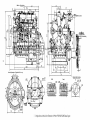
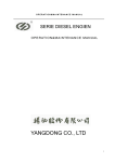
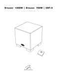
Connecting dimp!1sions of
flywhe~l
=~----,fl4
135
I
134
17Y - - - - r - n 9
214.7
i
201
and its hDirdng
~-J.Jf
530
~116H1r:'O~l
Exhaust outlet centerline
Vie", B
View~
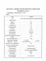
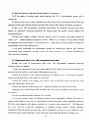
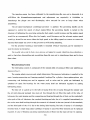
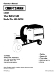
I. Configuration and Installation Dimensions of Model YSD490Q(YS490) Diesel Engine
1:2
~60
~46
....-
.....-
.....- -.....-
....- - - . - -.....-
.....-
..... Me
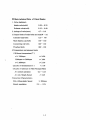
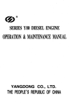
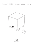
(N·m)
160
ISO
35
ge
25
(glkw·h)
250
1
230
1600'
n.
180Q.
2000
2200
2400
2600
2800
3000
3200
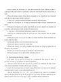
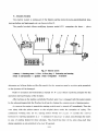
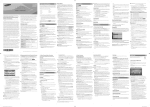
Performance Curves· of Model YSD490Q Diesel Engine
n
SECTION 1. DIESEL ENGINE SPECTFICATIONS AND
TECIINICAL DATA
I .Specifications of Diesel Engines (see Table 1)
Table t
Model
YSD490Q
Number of c;"finder
4
.Bore(mm)
90
I
Stroke(.mm)
I
CompreSSion tatio
_._----------_ .... --_._-------------_ ..
----
100
!
__
._--------~--.------'\_..
-------_ ..
_--_
18
........
_------ ....._----_._ ... _---------
Total displacement(L)
__
Fuing order
1-3-4-2
Rated PO\\ er(kW)
37.0·~45.6
... _~-~-_ ..
- -- ._--_.._-_._.. -
__._--------_._-----_.. _.._ . _ - - - .....-
.. _-------~-~-------------~-~-----~
.. _------------~----------------~-------------~-
----------_-_--_-_-·----_--_---ti----.---
~-----_-
.
2.54
Rated speed(r/min)
I
~
~
_
2600--3200
.. _-------_._----_._-_..~_._---------_ .._.-...!-. -------- ._-- -_._----.. ._--- --- .__._------_.._---- ---._--_.. __._------_._._--._.._.- _ ...._._.
~ 149.3
Max Torque(N m)
----_ ..._--_ .. _-------------------_.-._-_._-_ .._----_.-_. __ .-_._._--~_ ... _--------_. __ ..-----,-----_.... _._---,---_._._--
Min Specific fuel consumption at full load
(glkW.h)
--.---------..- --.----.....-.------------------.---+-..
---~------
.. ----------.. .- -----------....----.-.---.--.----.---.-----....--..-.----..- - - - 1
Oil- fuel consumption ratioC~)
~O.8
Advance I t~ection Angle/Speed
(Before TOC)
15± 1/2800
(OC)(rpm)
18± 1/2600
With Advance Device
!
Specific lube oil ccnsumption(g/kw.h)
i
I
2.72
Direction of crankshaft rotation
Countercloc·kwise
(facing to flywheel)
Cooling Inethod
Forced water cooling
Lll bricating method
Pressure and splash lubrication
Startting method
Electric
.---------- ---------.-.---.---------. ---·----·----------1-·-----.....--·-----------·-------- ..-------------------------·--------------..---------------1
230
Net lnass(kg)
OveraU dimensions
716X530X670
(LX WX H)(mm)
1-1
n.S~·ification of Main Accessories(see Table 2)
Table 2
Nil
l-Fuel injection
.
pump
~+
2
I
Designation
I Fl"
t
Type
r==
I
..
~ovemor _
Plunger diameter(mm)
~
Series Ior BQ pump
all-speed, mechanical centrifugal
=t
------
8
Single-acti;:-:----is--to-n----type----------
I
~~~!e set
i
F
YSD490Q
--------,
--i_--~el d~~ pu~
ue InJec or
I
Specification
ZCK154-S427?r CN-DLL~~~~~~~
_
•
I
~.E~~t:~~!~~eh~le(~Ei)
i
!
_
4 holes, <IlO.27
1
19.6+0
Injection pressure(Mpa)
--------1--------------------,----- ---------------------------------------------------I
~.-.----.-------!~~-------I--------------Rotor type
.
. _
3
I
Lube pump
I
1-----c:=~~1a~L)----1--------·----·-·-- ~~~: .--~--------------
!--------- ---------.- .---.-.----------- ----i--------·-------·----------·-------·----------------
i
i
.
Pressure(kpa)!
Type
.-+i
400
Centrifugal..
. . . volute,
---__.single-suction
.
-.----.--t---.--------.---.-----:---.-----------------------·--------------r-----------------------------·--------------. --.. ----
i
I
1.....-._-- .
!..
4
i
Water pump
I
I
5
...
.. - _ _ .
Speed(r/min)
I
---- .-...-
-
.
.
. __
4000
=~-)~~---=~===~==-~=
-·-·-·······-------t-.-------. -----.--Series
.-------------.----------DC motor
Type!
1- -- ------- - - - ------ - - - - - - - , - - - - - - - - - - - - - - - . - - - - - - - - - - - - - - - - - - - - - - - - - - -
I.
i
.
~-~-~~~-~~:~i~~~2 --4-----
-- .-t-.-.- --- ...-.-.-.--- -j--. -.-.
;
.
'l
Model
i
Startmg motor 1~-·----Vol~ge(V)------I~----
I
I
QD1315A,D138Y
.
12
.
r---------------------------I-------·-·----·-----------·-.--------
~
-------t---------·-
- --_.--_.-,
Power(kw)
2.5
I
------------Typ;---------··-l----------sil-i~~n
re~tifY~g-~huntdymam~--
f-·..-..-----------·-·-------- . ·--·--..------·---~-------··------------------- . - ----------------------.-----------------
Dymamo
6
ir---------------------------------Model --.---.----t------------------------_..---I
JFIIA
-------.--.--...Power(W)
i
350
-------------.-------------- ..--
!
f----- - ...----- --.--_.. -----. --- - - . - . - - - - - j - - . - - - - - - - -..- - - - - - - - -......- .... -- - - - - - ---.--------.------------------.--.-
.--
I
Voltage(V)
14
-.-------------f--.. ----------.-------.. ----------------.---r---------.--------.-------------.------------------1
-------1--· ... -
7!
.---,
8
I
I
Fuel filter
I-.------J~:I.-.--------f-~-.---------~!~gle sta~~:~~eleme~------_--
- - - - - - - , - - - - - - - - - - - - - - - - - - - - - - - 1 - - - - - - - - - - - - - - · - - - - · - - - - - - - - - - - - - - - - - - - - - - - - . - . -..---
.
Lube 011 filter
I
Type
f------------------------------.. -----..
!
Single stage,paper element
------------r--·---·----.---.-------.-----------.. ---------.. -------------.---- ...- - - . - - -
i
Model
I
J0801H
i.
!
!
Oil-immersed
9 \
Air titer
.--------...
------ --------..- T
--------y-p
_ -e
--------j ------------ . -..-.--..------.---..- -- -.. ---.---..---._-------.-----.---------- .---:
d
e l !t---·-----..---..--·---------------·--··--------------------------.
CN212
-.. --.. . --.)": --. -..------·..·-----.. --_.. ---·--1------------·-·...--------..M
.--.. -.-----.o-----_.
.--------.
.----------.-.. _- ! Electrothermic
!
Type
i
Shrorded
10 :
-------!--- ---.-..---.----------------..---_.,,-. --.--.------. -----------.--------------- . .--.------------- ---!
plug
I
Model!
Nil accessory
I
------1"- - .. ---------.---...--.--.. +-------------.--------.--------..----..---------------·1--··---·--------..- - - - - - - - - - - - - - - · - - - - - - - - - -
f---
-.---- .. - . - - - . - -..- - --.-_.-.-----.....
1-2
ill.Main te4:hn.ieal Data of Diesel Enline
1. Valve lash(mm)
Intake valve(cold)
0.30- 0.35
Exhaust valve(cold)
0.35- 0.40
2. sinkage ofvalve(mm)
0.7- 0.9
3.Torque limits of main bolts and nuts(N· m)
Cylinder head bolts
125- 145
Main bearing cap bolts
140- 160
Connecting rod bolts
100-.." 120
Flywheel bolts
100-.... 120
4.Temperature and pressure limits
(l)Exhaust temperature(OC )
n~
t~
620
3200rpm>n>2600rpm
t~
600
n~
t~
550
~
100
3200rpm
2600rpm,
(2)Lube oil temperature(OC )
(3)Lube oil pressure in Main Passage(Mpa)
At normal operation
0.2- 0.45
.l\t luin. Steady Speed
? 0.05
5.Govemor Characteristics
Min. idling steady Speed
Steady regulation
~
900rpm
5% -- 10%
]-3
IV' .•~it Clearance and Wear {.limit of Main Parts(see Table 3)
Table 3
I
I
Assenbly limit' Wear linlit
Designation
(mm)
(mm)
Connecting rod journal and connecting rod bushing
0.060-0.172
0.25
2
Piston pin and connecting rod small end bushing
0.025-0.050
0.10
3
Piston skirt and cylinder liner
..._._-_..-
.•_._ ..
-_.•-
--.._ .. _
0.130-0. 195
'-"'-_- .. _
~
- .• _._ _ •. _-_
- - -•.... -
- - . __•... _ ·1
4
Side clearance bet\veen the .~ st ring and its groove
5
Side clearance
6
Side clearance bet\veen the oil scraper r~ng and its groove
7
Gap of the 1st ring
bet~reen
the 2nd ring its groove
~·.·
O.070-0~ 102
0.20
0.050-0.082
0.15
0.030-0.062
0.15
-_
_ _._._- --.- .,
_.. +--.- ..__.. ---.---- ---..- .. -t
8
Gap of the 2nd ring and oii scraper ring
0.300-0.450
9
Crankshaft main journal and main bearing
0.070-0.149
••. ' •• _ • •
rCalTIstlan.. journal and bushing
] 1 Idle gear shaft journal
__
- """'"
--
·-.·--------.---······-·I
..
0.300-0.450
_._.'--' -' ..- "-'--" .. _
....-- - -_
0.40
_ . __ "''' __ ···_····__ ·•
~nd
-
- .-
0.25
•
c
__
0.18
0.025-0. 114
bushing
- ..- "'-'-'-'-_._._ --
~.,
0.025--0.075
..-
..__
- - - - -..-.- - -_.- ..- __
-.--+-- -..-
- ,,----
..
0.18
-----+-.-
--..- --
12 Intake valve stem and valve guide
0.025-0.077
0.15
13 Exhaust valve stem and valve guide
0.040-0.092
0.15
14 Rocker arm shaft and bushing
0.016-0.061
0.20
15 Axial ClearcltlCe of crankshaft
..
-_ .._-.. _ -._"
-
- '-1
0.075-0.265
-_._--
_.._
16 l\xial clearance of canlshaft
_.. --.- ..•... -
_. __ ._
-
...,
_--
_. __ ._---
_
0.080-0.250
1-4
_
.;-
_
-
--""'.'--"-"-'
._..
SECTION2. OPERATION
I . Fuel Oil ,Lube Oil and Cooline Water
I.Fueloil
Users can select the proper
the
~eneral
fuel.Use
area in China,the
~rade
fuel.Before
~ade
~de
of fuel oil
of fuel oil is
accrdin~
accordin~
to the local ambient temperature.'.Jn
to the standard GB252
li~ht dies~1
"0" light diesel fuel in summer, while in winter, use grade "- 10" light diesel
bein~
filled into the engine fuel tank,the diesel fuel must be settled for a long period
(normally at least 48 h).Then draw out the upper part.The fuel should be filterd by silk cloth
while filling it into the engine fuel tank.It will extend service life of injectors and injection
pumps by
usin~ the
well settle diesel fuel.
2.Lube oil
In the ~eneral area in China,users can select the proper' grade according to GB/Tl1122
Lube Oil of Diesel Engine.Use grade CD40 lube oil in summer,while in winter use grade CD30
lube oil.When
bein~ filled
into the engine oil tank,the oil should be filtered by screen.
3 .Cooling water
It is recommended to use soft water such as rain water,city tap water,or clean river water for
en~ine
cooling. Well water or tap water
f~om
well water could not be used. Cooling water
containing too much minerals will form water scali in an engine cooling system,affecting the
engine cooling efficiency and giving rise to engine troubles.
Hard water(well or spring water,etc.) should be softened before being used.There are two
softening methods;
(I )Boiling up the hard water;
(2)Adding 20g caustic soda (sodium hydroxide) to each 30L hard water to make up a
solution.
When the engine operates in cold weather where the cooling water is liable to freeze,anti freezer can be added to the cooling water to prevent it from
freezin~.
Glycol or alcohol aqueous
solution is most ordinary.
If it is difficult to start the engine under IOYler ambient temperature, heat the water to about
80°C before filling it into the cooling system.
2-1
II .Preparation before Startine
ti~htness
I.Check the
control lever and
and reliability of ali
stoppin~ lever)
connectin~
parts. Check control levers (speed
to see whether they can be moved freely.
2.Rotate the crankshaft several turns"be sure that all
movin~
parts move freely.
3.Check the oil level in the oil sump and injection pump to see whether it is kept within two
marks on the dipsticks.Make sure that the fuel tank has sufficient fuel and that the fuel
pipel~nes
are unblocked.
4.0pen the fuel tank cock..Check whether there is a.ir in the fuel system. If necessary,Joosen
the vent screws on the fuel filter and injection pump,operate the
primin~
pump on the fuel
delivery pump by hand until the fuel flows out of these screws without bubbles,and
vent screws.After that, loosen the union nuts of injection pipes on the injectors
reti~hten the
an~
rotate the
cankshaft to bleed air from in1ection pipes,then retighten the union nuts. Check all fittings of the
fuel system to see whether there is any leakage at all joints.
5.Check the radiator to see whether it is filled fully with water and whether there is any
leakage at all ioints.
6.Check the accessories to see whether they are firmly and reliably connected.Check the
electrical system to see whether the battery is fully charged,all wirings are correct and all
connections are tightened.
7.Check the clutch to see whether it has disengaged.
m. Startin2
1.Set the speed control lever at the middle speed position.
2.Tum the ignition switch to "preheating" position to heat the electrothennic plug for
20r~.
30s.
3.Turn the ignition switch to "on" position.Press the starting button to start the engine.lf it
fails to start.,release the button immediately. Wait 2minutes 3 Ininutes.. before starting the engine
again.lfthe engine fails to start after 3 attetnpts.,check the cause and remedy the fault.
4.As soon as the engine has been started.xelease the press button itnmediately.Then tum the
ignition switch to another position to charge the bat1ery. At the same titne move the fuel control
lever until the engine runs at idling
speed.C~heck
the operation condition of the engine to see
whether there is any abnormal noise.EspeciaJly pay close attention to the readings of oil pressure
gauge, which should be within specified pressure limits."Then \varm the engine up with engine
speed gradually increasing to
1800-~-J
2000r/min
2-2.
IV . Operatin2
1.00 not load the engine until the cooling water telnperature is over 50°C and the lube oil
temperature is over 40 "C . The engine should not be operated undrer rated operated under rated
output before the outlet water temperature reaches approximately 80°C .
2.1ncrease or decrase the engine load and speed gradually and evenly.In normal case,do not
load and unload the engine suddenly.
3.During operation,observe the gauges on the instrument panel frequently where the
readings should be within the specified limits.Pay close attention to the exhaust gas color and the
operatingnoise.lfthere is any fault..stop the engine and inspect it.
v . Stoppine
1.Before stopping..take off the load and reduce the engine speed gradualJy.Let it run at
idling speed for a fe\\' minutes.Do not stop engine until the outlet water temperature fans to
below 70°C.
2.A fier stopping the engine, the ignition s\vitch should be turned to the middle position.
3.1n winter,when ambient telnperature falls to bellow 5 °C ,after the engine stops and the
cooling \vater temperature falls to below 60 "C~ .,open all drain cocks on the cylinder block and
radiator to drain off all \vater remnant within the cooling systelTI.,in order to avoid dalnages 01
parts due to freezing.If anti ---.__. freezer is added to the cooling water,it is not necessary to drain
off.
2-3
SECTION3. MAINTENANCE
For reliable engine operation with less wear and longer service life,all maintenance work
must be carried out as follows.
I . Routine Maintenance
I.Check the oil level in the oil SUlnp and it should be between two marks on the dipstick
and near the upper one.For a new engine or the engine reused after stopping for a long period,the
lube oil must be filled to the upper mark,and operate the engine at lower speed for 5 ----- 10min,
then stop the engine and measure the lube oil level once again.
2.C:heck the cooling water level in the radiator.
3.Check the lube oil level in the governor of the injection pump,replenish the oil to the
specified level if needed.
4.Eliminate oil"water and gas leakags of the engine.
5.Check tightness and correctness of all components attached to the engine.
6.Check tightness and reliability of engine foundation bolts and the
conn~ction between
the
engine and the dirven Inachinery.
7.Keep the engine clean.Oil,water and dust gathered on the engine surface should be wiped
away \vith a dry rag or cloth dipped in gasoline.Especially keep the electric equiplnent clean and
dry and clean out the dust on the fins of the radiator.
S.For the new engine"after SOh t(ial running,renew the lube oil in the oil sump,fuel injection
pump and governor,and tlush the oil filter elclnent,oil sump and oil strainer.
9.Promptly elinlinate the troubles and faults found.
II .Maintenance after Every 100 Accumulated Operatine Hours
Besides the ,. routine Inaintenance" \vork,and the follo\ving items:
1.Rene\v the oi I in the sump.
2.Clean the oil filter or renew the paper element if necessary.
3.(~lean th~
fuel filter or renew the paper element if necessary.(1t may as \vell be replaced
after every 200 acculTIulated operating hours.)
4.Clcan the oil filter or renew the paper eletTIent if necessary.
5.(~lean
the valve lashes.. readjust theln according to the recotTIlnended procedure if
necessary.
3-1
6.Check the tension of the fan belt,and readjust it if necessary.
7.Fill the nipple of cooling water pump bearing with ZG- 4 calciumbased grease with a
grease gun.
8.Clean out the dust in ,intake manifold'lclean the inside of the aircleaner,brush otT the dust
gathered on the paper element surface,and clean the inside of the exhaust manifold and silencer.
9.After every 200 accumulated operating hours,check the injection pressure and spray
pattern of iniection.lf necessary.. dismantle the injector,clean the nozzle set,and readiust the
injection pressure.
IO.Check the voltage of battery and the specific gravity of battery acid . which should be
within 1.27 r'_ 1.28(at ambient temperature of 20°C ). When it is less than 1. 14,the battery should
be recharged.The level of battery acid should be I 0 .'~--, 15mm above the pole plate.lf insufficient
add distilled water to the required level.
11.AII parts dismantled for maintenance should be washed,and cleaned and correctly
reasselnbled.l\fter reasselnbly.stat1 the
~nginc
and check \vhether it is in proper operation,AII
faults should be retnedied.
ill .Maintenance after Everv 500 Accumulated Operatine
Besides the work of Inaintenance after every 100 acculnulated operating hours.. the
following items are needed:
I.Check the injection pressure and spray pattern of the injector.lf necessary.. dislnantle the
injector'lclean the nozzle set and readjust the injection pressure.
2.Check fuel delivery of the injection pump,and recalibrate it on a test bench if possible.
Check the injection tilning,and readjust it if necessary_
3.(~heck
the sealing of the intake and
~xhaust
valvcs.lf necesary . grind and lap the valve
seats and readjust the valve lashes.
4.Check the tightness of the connecting '.>a roo.,mian bearing cap and flywheel bolts.
5.Retightcn the cvlinder head bolts and adjust the valve lashes according to directions given
in section 4.
6.C:Iean or replace the paper elclnent of air cleaner.
7.('lcan the cooling
~ystem.T'he cleaning
solution can be prepared hy adding 150 granls ot
caustic soda(Na()H) to every litre of v~ater.Before cleaning_drain the systelll cOlnpletely and then
fi II in the saIne capacity with cleanIng solution. Let it relnain in the systenl f<lr 8 -~ 12h.Then start
r-
the en.glne and run it until the tenlperature of cleaning solution reaches normal operating
tClnperature.Stop the engine and drain the system itnnlediately in order
10
avoid settling of scale
\vithin the systetn.Final1y,tlush the system with clean w'ater until all seditnent is flushed out.
3-2
8.Check whether the thermostat is in good order.Examine the water dropping out from a
weep hole of the water pump. It is necessary to renew the water seal,if flowing out too much of
water.
9.Check the wiring contacts of the electric equipment to see whether they are connected
firmly and well.Bumt marks should be removed.
1O.After every] ,000 accumulated operating hours,add the following items;
(1 )Make an overall check on all parts and components.Make necessary adjustments and
repairs.
(2)Dismantle the dynamo and starting motor.Clean out the dirty grease in the bearings and
refull thern with clean grease.Check the pinion of starting motor.
II.After every 1,500 accunulated operating hours,add the following items:
(t
)Rernove the cylinder head,check the valve and valve seats and other parts of cylinder
head asselnbly.
(2)Remove the carbon
d~posits
on the surfaces of cylinder head,liner, piston and piston ring,
etc,and wash down them.
(3)Check and measure wear of the pistons and piston rings.
(4 )<.-:heck and rneasure wear of the cylinder liner.
(5)Check and measure \vear of the crankshaft main journals and crank pins.Clean lube oil
passages of the crankshaft.
(6 )Check \vear of the Inain bearing and connecting- rod bearing shells.
(7)Clean oil passages of the cylinder block and replace lube oil.
IV .Preservation and Stora2e of En2ine
If the engine is to be put out of service for a cOlnparatively long period of time,it is
necessary to preserve it according to the follo\ving procedure:
I.After the engine stops and still does not cool yetdrain out conlpletely the lube oil,cold
water and fuel itnrnediately.Clean the oil sump and oil strainer.
2.Clear out the dust and oil on the engine surface. With antirust oil sinear all the unpainted
exposed surfaces of engine except rubber and plastic parts.
3.Heat the filtered lube oil
~rhen
10 ) 10
120 'C'; . until all bubbles in the surface of oil disappear.
pour the dehydrated oil Into the oil sunp until oil level reaches the upper mark.,and turn the
engine,in order to nlake sure that the lube systenl is cOlnpletely tilled up with this oil.
.1-3
4.Pour some dehydrated oil into cylinder through injector -
assembled holes on the
cylinder head,and turn the crankshaft to make sure that the piston,piston ring,cylinder liner and
valve seat are alJ covered with a layer of this oil.
5.Block the outlets of intake and exhaust manifolds (silencer)with wooden plugs or wrap up
properly with plastic film in order to prevent any dust from getting in.
6.The engine should be stored in a clean room with good ventilation and low humidity.,The
engine should be covered.Chemicals near it are strictly prohibited.
The preservation according to the above procedure may be valid for 3 months.Over this
period,repeat the procedure.
3-4
SECTION.4 ENGINE ADJUSTMENT
I ..-\d.iustJnent of Valve I.J3sh
When the engine is maintained and repaired.,it is necessary to check and adjust the valve
lashes.'fhe recommended nlethod of adjusting the
valve systenl and valve lash is as follows:
1.Remove the cylinder head
cover.(~heck and
tighten the nuts fastening the rocker aml shaft
stands.
2.Turn the crankshaft to rnake sure that the
piston of 1st cylinder is at the conlpression TDC
position.'The tirrling nlark on the inspection window
of the fly\vheei housing exactly points to the '.
tnark on the tly\vhecl ritn '!or
th{~
"
011
rnark on
0"
th{~
crankshaft pulley is aligned \,,"ith the pointer on the
cover ofthning gear housing.
3. slip a feeler gauge between
th,-:~
rocker arnl
and the tip of the intake or exhaust valve steins of
Fig. t Adjustment of valve lashes
the 1st cyl inder respectively to check and adjust the
valve la~;,hcs.lntake va.ive lash
and exhaust valve
tash in cold l11ust be tht: value specified in section) .1l·len after turnin~~ the crankshaft by 180"
to adjust the valve lash of other cylinders according to the engine firing order(! - 3- 4-2)for the
four cylinder engine and' -3-2 tor three cylinder engine.
II. Adjustment of In it~tion Tiolinf,!
1\1 obtain the tnosl econon1ical specific 111ei conSllInption and to ensure norlnal operation of
th~
engineJnjection tirning should be adJusted properly.For the Model 485
die~el
engincs,the
ang)c at \vhich injection begins should be the value specified in section I .
'fhe adjusting inl~thod of injection timing is as l(lllo\\'s:
1. Vent the air trapped in the fuel system'land t, ~ln the crankshaf-t to f111 up the injection
pUlnp \Vl!h fuel.l)isconnect Hle injection pipe of the 1st
cyiinder..turn the crankshaft slowly in the
direction of its rota[;on and at the satne tin1C ohserve the fuel level in the hele of fuel pipe union.
\Vhen this fuel level iust starts to risc'!stop lurn the crankshaft imtnediately.
4-1
2.Check the timing mark on the inspection window of flywheel housing to see whether it
aligns with the correct gradulated mark of specified advanced injection angle on the flywheel rim
(or on the crankshaft pulley).
3.ln case that they do not match \vith each other,the advanced injection angle can be
adjusted by removing, off the front cover on the tinling gear housing and loosening the three
screws fastening the injection plunp tilning gear support(see tig.2).lf the injection timing is too
advanced,turn the timing gear support anticlockvvise to the proper angle.Otherwise.turn the
support clockwise.If adjusting range is not enough
due to limitation of the three elongated holesJoosen a
little the three fastening nuts on the triangular flange
of the injection pump and tum the injection pump.
Facing the front end of engines,when the injection
pump rotates clockwisc,the fuel injection will retard;
\\lhile
the
pump
rotates
anticlockwise.Jhc
fuel
injection will advance.
4.Additionally,if the engine has injection angle
advance device,the advanced injection angle can be
adjusted hy
loosening the three nuts on
the
triangular flange of injection pump and turn the
injection pu,np shafLFacing the front end of engines<t
\vhen the injection pump rotates clock\vise,the fuel
injection
will'
retard:while
the
pump
rotates
Fig. 2 Adjustment of specinect
advanced injection angle
anticlockwiseJhe fuel injection will advance.After
turn the injection pump once. it is lnust to tighten the three nuts and c.heck the advance injection
angle again untill the advance injection angle fits the spcified value.
ill. Ad.iustment of Iniector
Injector test and adjustment ,nust he performed on a injector tester in order to adjust
iniectin~ pressure"inspect
sprary pattern and relnedy faults.
Too high or too lower Injector injecting pressure,and abnormal spray on dalnaged injector
parts'\vill cause engine troubles'lsuch as black smoking,power and speed dropping..increasing
exhaust temperature and diesel knocking.,etc.Generally..the "shut off" method is recommended to
4-2
check a fauly iniector,Le.loosen the nuts of iniection pipe from the injector of every cylinder
successively,and observe the exhaust smoke. When the cyl1nder with the faulty inlector stops
firing~black smoke
wouid disappear and engine speed is not appreciably affected or not affected
. at all.It may also be checked by listening to the chattering action of the injector of every cylinder
\vith the flywheel rotating.Ifthe
d~stjnct clear
sharp sound of certain cylinder could not be heard,
the injector in this cylinder may be faulty.
I.Procedure of injector testing and
adjustnll~nt
(1 )W ()rk the injector tester hand pump unti I the gauge pressure reaches about specified
injection
pressur~.
'rhen operate the hand pUlnp slo\\'ly and adjust the inlection pressure
at
\Nhich injection begins.'rhe nozzle should not sho",' any si~~ns of leakage. If fuel drips around the
nozzle tip after several tests.,the nozzle set must be dismantled for cleaning and
~'Tinding~"'hen
test it again.
(2)Rernove the lock nut,turn the adjusting screw to get the pressure at the beginning of
injection which should be specified value in section I.Then tighten the lock nut,and test it again.
(3)Work the hand pump at a rate of approxirnatetv 1 stroke per second and observe the
nozzle spray 'The fuel spray shoulJ be even,and well atomized in a shape of cone.At any cross
section of the conc,the atomizt:d thel should be finely and evenly distributed.Fuel droplets and
irregular pattern \vhich can be seen by naked eyes should not be present in the spray_ There
should be a distinct clear sharp sound at the end of iniection.Generally"ilTcgular pattern of the
spray is caused by needle valve
seizure~fuel
drrpping is generated by danlaged conical sealing
surface of needle valve and spray spIlt results frorn carbon deposits on the tip of nozzle and its
heat
dt~fornlation.
2.Iniector dismantlclnent and repair
(' i )Before dismantling the injector.clean off the dirt gathered on 1t
,(~lamp
the nozzle body
in a vice lined by copper sheets on its law \\lith the nozzle up\vard.rrurn off the nozzle cap nut
and take out the nozzle set,[)ra\v
Ollt
1he needle valve from the nozzle body and soak it in c.lean
tllei oil.Then clalnp the injector in the vice upside dow'n again.Disnlantle the adjusting nut,and
adjusting scre\v,then take out the lnlcctor spring and splndle.
(2) If the nozzle set is seized or elnits fuel badlv.it
in fuel oil tc)r a while.and clalnp the needle valve by a
draw it out slo\vly,iust to avoid scratching its
nHl,St
he cleanecl.Soak the seized nozzle
p1it:~rs
with cloth lined.Then rotate and
su~'fac.e,Decarbonize
the needle valve and nozzle
body 'Nith wooden chip soaked in fllCI oi1.It is forbidden to clean them with
4-3
111 eta I
chip. If the
guiding surface of the needle valve and nozzle body is not smooth enough,it may be lapped with
a little bit of clean fuel oil,then clean off any metal particulates in clean fue1.While lapping of
needle valve with nozzle body..never knock the needle valve against the body.
IV . Ad.iustment of Lube Oil Pressure
See fig.3.Lossen the lock nut and turn the adjusting screw with a wrench to take the lube oil
pressure within 200
.'~
400kPa(in cold state the pressure may be higher slightly). f\fter
adjustment.the pressure adjusting screw must be locked by the Jock nut.
v . Adjustment of In.iection Pump
The injection pUlnp has tested and calibrated at
the
factory.If
it
is
necessary
to
readjust,the
readjustment must be perf(}nned in a injection pump
test bench with a standard injector and injection pipes
of standard length according to the instructions in
Operation Manual of the Injection PUlnp.
VI .Adiustlnent of Decompression Arm Lash
Fig. 3 Adjustment of lube oil pressure
Turn the crankshaft to make that the piston of 1st
cylinder is at the conlpression T.D.C. position.Turn the decompression arnl to decompression
position.Loosen the Jock nut.Turn the adjusting screw to bring just into contact with the lock arm
of intake valve (i.e.no valve lash).Screw the adjusting scre,v by 3/5--.-4/5 turns again (Inake the
intake valve lifling to 0.6--- O.8mm ).~rhen tighten the lock nut.After this"according to Item 3 of"
f\diustlnent of Valve Lash",
nlake the piston of another cylinders at the compression TDe
position one by one and adjust by the same method.
4-4
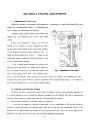
SECTION 5. CONSTRUCTION OF DIESEL ENGINE
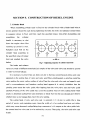
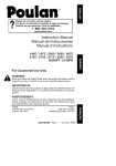
I . Cylinder Head
When assembling,cylinder head is fixed on the cylinder block with cylinder head bolts.A
torsion spanner should be used during tightening the bolts.T'lle bolts are tightened several times
in sequence shown in Fig.4 until they reach the specified torque Bmit.After dismantling and
asseJnbling
the
cvlinder
head.it is necessary to shut
down the engine \vhen first
wanning up period is over.
Retighten each bolt on the
cylinder head according to
the specified value of torque
J.hnit and readjust the valve
lashes.
+-e--+
Fig. 4 Tightening sequence of cylinder head bolts
The intake and exhaust
valves arc made of different materials. Each couple of the valve and valve seat should be ground
in order to prevent leakage.
It is necessary to grind \vhen gas leaks out due to burning out'lmechanical pitting and "vear
appeared on the sealing face of valve and valve seat.When grinding'lapply a grinding paste(tlne
valve sand)on the conic [.;ealing surface of valve.l~hen the valve and valve seat are lapped in pair
unitJ a even.continuous and lustreless sealing band appears.1t is strictly forbidden that the
grinding paste enters the valve guide.After lapping.,clean the valve.valve seat and valve guide
carefulty.\Vearing of the valve guide may CC:l.use the eccentric wear of valve sealing band which
results in abnormal sealing.Pour sOlne kerosene or diesel fuel into the gas passage'land observe
\vhether there is any leakage.then check the valve sealing.
l~he
sealing band of valve and valve seat is normally 1.2'-,·1.6 mIn in width ..After a long
period of service and regrinding many tinlcs,the V\idth of v?lve sealing band nlay get wider..
vvhich may cause abnormal sealing.Being kept concentrica! \\.tith respect to the valve guide hole'!
the contact band on valve seat is to be refaced by a reanlcr.'Then gring the valve and valve seat
in pair.
5-1
.A fier service for a
and
period
long
regrinding
many
times.
the sinkage '\NiH increase.
When it exceeds 2.0mm.,
replacing the valve seat
should be considered.
Check
valve
the
trequently.T'hc
lashes
adjusting
recoITunended
lnethod
is
shown
,Fig. 5
on
V'alv~
sinkage
paragraph I of Section 4,
If the lashes are too largc.,it lnay affect the correctness of valve tinting and the noise level o'f
valve device dses.On the contrarY'tit rnay cause leakage or valve burnt out.
II. . Cylinder BLock
l'he cylinde,f block is lnade of cast iron and is of crankshaft centerline oft:. split face
structure. f3esides the fitting hores for the hncr and the cylinder head boltholes,on the top plane
of the block 'there are holes leading \vater to the cyiinder
there'
are
channels
h(~ad.N0ar
the fear end of the block
delivering
!ube. oil upvvBrd to the cylinder
head.
T'he "vater pump is lnounted
on
the
upper
cylinder block
front
face
.,and
of
the gear
Fig. 6 Prot.rueliog beig,bt of the Uner Dange plane
system is on the lower part.'fhe
relative to the plane of cyUnder block
tly\vhecJ housing is installed at
the rear face of the b!ock.()n the block
plnnp and tap holes
l()f
ho1tonl~therc
are a lube oil inlet,a hole tor the lube oii
installing the sUlnp.There are a side cover and a hreather on the left side
of the block(facing to the front end).l'here are the lube oil
right side of this block 'fhe ITtain lube oil
oil passages
deliverin~~
lin~
filter'\fut~J
and Its branl;hes are
filter and drain (;ock on the
arran~;ed
in horizon,The lube
lube oil to the camshaft bushes are slant. When dislnantling and repairIng
5-2
the diesel engine,flush all lube oil passages,and be sure that they are clean and unb locke~. All
passage plugs should be sealed reliably and leakproof.
The main bearings are of complete suspension- support type.Since the main bearing caps
and cylinder block are matched to bore,the matching marks are both on the bolck and main
bearing caps.Misplacement or inverted installation,when assembling,are prohibited.The main
bearing shells are made of high- tin aluminium-base alloy. When dismantling for cleaning,be sure
that the upper and lower bearing shells are in right places(the upper shell with an oil groove).The
crankshaft thrust plates are assembled on the last main bearing with an upper piece and a lower
piece on each side.The thrust plates bear the axial force [roln the crankshaft.There are oil
channels on its operating surface \\!hich should be located
a~ainst the
thrust planes on the crank,
and its back surface is smooth.Never locate therTI in reverse.When tightening the nlain bearing
biots,t\\'O bolts on the bearIng cap should be tightened several times in
tl1rn.L~efore
tightening the
Inain bearing cap,strike the crankshaft for\'vard and backw'ard in order to keep the upper and
lo\ver thrust plates in the saIne plane.Then tighten the bolts until they reach the specified
tightening torque. When cOlllpleting the c.rankshaft assemblY,turn it at the flywheel cnd by hand
to check \vhether it can be rnoved freely.
l'he Iiner is slipped into the cylinder bore vertically so that deformation of the liner Inay be
avoided.rrhe liner flange plane should protrude out the top plane of cylinder block by 0.07--- 0.] 5
lTIln
to keep an excellant scaling bet\vcen the cylinder liner aud cylinder head,as shown in Fig6.
III . Piston and Connectin2-rod
'The piston and connecting- rod assembly conlprises the
piston~piston
rings,piston pin, re-
tainIng f1n~:-.. connecting-rod,connecting rod cap,connecting-rod bolts and connecting-rod bearing
shelts and bush,etc.The lnass difference of piston and connecting- rod assetllblies in the sanle
engine should be vvithin 20g.
/\11 of the cOlnpression rings are made of alloy cast iron.l'he outer circle surface of the first
rin,g is plated with porous chronlC in order to decrease the \\Jear between the cylinder liner and
piston ring.rrhe second ring has a conical surface. W·hen assenlblinp,,,the surface rnarked with a
sign Up " should be kept against the top of piston and be careful to avoid assenlbling in reverse.
II
The oil-control ring is oftensionin~, ring type.'The radial force of oil ring is still kept while
decreasing the elasticity due to \vear:rhus the service life of oil ring is prolonged.
5-3
Check the ring end gap before
assembling the piston ring.The method
measuring this gap is recommended as
follows: Press down the
piston ring
evenly into the cylinder liner by 15-20mm from the top surface of liner.
Measure the clearance with a feeler
gauge.In
normal
case,the
2
measuring
3
Fig. 7 Measurement of piston riog end gap
1. Thickness feeler (gauge) 2. Piston
ring
3.. Cylinder liner
value should be O.2--0.4mm(Fig.7).In
case the gap value is less ,enlarge it by
a file.If it is excess,replace it with
another one.In addition.,measurement should be Inade with a feeler(gauge)to check the side
clearance between the piston ring and
ring groove.The side clearance for the
first ring should be
O.07r~O.1 02mm
and
o.
05---0.082mm for the second ring as
shown in Fig8.
When disnlantling and asselnbling
the piston ring,a special tool may be used.
'fhe ring end gap of piston rings should
be set off with each other by 120°C to
Fig. 8 Measurement of side surface
gap of piston ring
prevent being in line with the piston pin
seat hole.
If the piston ring is seized and could not move when checking,soak it in diesel fuel(kerosine
or gasoline)for 24h or more.l'hen knock the piston ring slightly to tnake it become flexible of
itselt~On getting
out the piston ring,clean it in diesel fuel or carbon tetrachloride.
Check the piston to see whether there is any cracks or scars_Change the defective piston and
renew its rings.
The cross section of the connecting- rod is 1- shaped,with the splitting surface of large end
being perpendicular to the center line of connecting- rOd.Boring the connecting- rod hole and
connecting-rod cap must be
Inated.l~herefore
when assembling,pay close attention to the mating
5-4
marks on both the connecting- rod and connecting- rod cap in order to avoid making mistakes.
The connecting- rod bearing shell is made of steel with high tin aluminium alloy.When the
clearance between the connecting- rod bushes and crankshaft journal exceeds the specified value
after wearing or severe stripping and burning occur on their surfaces,they must be renewed in
pair.
During engine overhaul or renewing the connecting-rod,check the axis parallelism of the
connecting-rod small end to the large end,which is specified to be within O.Olmm/IOOmm(both
in vertical and horizontal direction).If it goes beyond the scope,alignment should be made.
Before dismantling the piston and
~onnecting-rod assembly
in cylinder liner or assembling, ,
it is necessary to scrape and clean the carbon deposit and greasy dirt on the top part of cylinder
Iiner.Before assembling,smear some clean oil on the cylinder liner bore,external surface of
piston and piston rings,connecting- rod bearing shells and crankshaft journal.Then place the
piston guide sleeve in the cylinder liner.Jlt the piston and connecting-rod
a~selnbly
into the
cylinder liner carefully,and tighten in tum the connecting-rod bolts according to the specified
tightening torque limit in several separate times.After finishing the assembly,turn the crankshaft,
be sure that it rotates smoothly.
IV • Crankshaft and Flywheel
The crankshaft timing gear and pulley are fitted on the front output end of crankshaft.
Positioned by the locating pin,the flywheel is fitted on the rear end flange of the crankshaft \vith
six bolts tightened according to the specified torque value.A bearing E60203,\vhich supports the
transmission shaft of gear box,is fitted on the flange center at the rear end of the crankshaft. An
angular calibrating line is marked on the crankshaft pulley and a pointer"which is fitted on the
cover of the timing gear housing,indicates the reading of advanced injection angle.
A flywheel gear ring is bound on the outside diameter of flywheel in shrinking fit.A
calibrating line.,\vhich provides observation for advanced injection angle,is marked on the
flywheel.
v. Camshaft
'fhere is a gear driving the lube oil pump in the front of the last set of cams(facing to the
front end). When the camshaft revolves,the earn on the shaft drives the tappets,push rods,valve
rocker arms and valves,which respectively control the intake and exhaust valves for each
cylinder.
5-5
There is a thrust flange at the front end of camshaft,and a thrust plate of camshaft is located
at the front end to control the camshaft axial moving. The lube oil is delivered to the camshaft
bushings separately through the main oil line.Before assembling the front bushing of camshaft,
check whether the oil holes on the bushing and oil passage in the cylinder block cOlnmunicate
with each other. As the camshaft gear is engaged with the driven gear oiNhe oil pump,therefore,
before dismantling the camshaft,it is necessary to disassemble the lube oil pump,then draw the
camshaft out from the front end.
The axis of the tappet deviates from the center line of canl width .During operating,the
tappet rotates so as to provide an even wearing on the bottom surface and the cylindrical surface
of tappet.
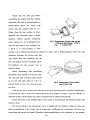
VI . Gear Transmission System
l'he gear transmission system consists of the crankshaft timing gear..tilning idler'lCanlshaft
timing gear,injection pump timing gear and hydraulic pUlnp gear.
Except the hydraulic pump gear,all the titning
~"ears
are all Inarked with timing signs which,
'Nhen assembling,should align \vtih each other at the nleshing position (the single tooth marked
with a sign is inlaid bet\veen the
t\VQ
adjacent Jnarked teeth)in order to ensure the tnOVenlent
relationship of a.11 nloving parts,as shown in Fig.9.
Fig. 9 Timing gear meshing signs
5-6
Special tools are necessary for dismantling or assembling the crankshaft timing gear.The
camshaft timing gear can be got out by two bolts M8 on the gear spoke which are turned
staggeringly and evenly.The timing idler is located on the cylinder block by slide fit.The
injection pump timing gear is assembled on the timing gear seat which is fixed on the camshaft
of the injection pump.Whenever three bolts setting the injection pump gear are loosened,the
injection pump gear can be drawn out.The injection pump gear is pushed out when the three
bolts M8 X 35 are staggeringly tigbtened on the gear seat.
.
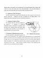
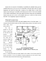
VB.Fuel and Governin2 System
The fuel and governing system is the main operating section of the diesel engine . It is
composed of the fuel delivery pump, (uel filter, injection pump, governor, fuel injection and fuel
pipes,
return
etc.as
shown in Fig.IO.
'The
fuel
is
2
pumped by the fuel
1_~_--3
delivery
pump
from
4
the fuel tank into the
5
pump
injection
through the fuel filter.
rrhe
diesel
fuel
IS
delivered through the
inlection
pipe
under
~ pressure
high
produced in the pUlnp,
and is then atonlized
by the injector before
burning
in
the
Fig.l0 Fuel and governing system
1. Fuel return pipe 2. Fuel injection pipe 3. Injector
4. Injection pump S. Fuel filter 6. Governor 7. Fuel delivery pump
COll1bustion chanlber.
rrhe fuel delivery
ptunp is a single-acting piston type pump located on the outside of the injection pump. The
eccentric cam,which is set on the camshaft of injection pump,dnves the fuel delivery pump"
\vhich finally presses the fuel into the fuel cavity in the injection punlp.
5-7
The injection pump has been calibrated by the manufacturer.Be sure not to dismantle it at
will. When the dismantlement,repairment and adjustment are required,it is forbidden to
interchange the pluger sets and discharging valve sets,and be sure to keep clean when
assembling.
The all speed mechanical- centrifugal governor is applied. The governing handle can be
operated to control the speed of diesel engine.When the governing handle is turned in the
direction of tightening the governing spring,the fuel supply would increase and the engine speed
\\-'ould be up consequently. When this fuel supply would decrease and the relevant engine speed
would go down.Do not move either the high speed or the idling speed set screws or screw the
maximal fuel supply set screw on the governor at will during operating.
On the governor housing,a stop handle is mounted which,if necessary,can be operated to
stop the engine at emergency.
'rhe needle valve and its body are a precise set lapped in couple . therefore.,close attention IS
paid to that,when dismantling and assembling them.Be sure not to interchange them and to keep
them clean.
VID.Lubricatine System
The lubricating system is composed of the strainer,lube oil pump,oil filter and pipelines,as
shown in Fig. II .
rrhe engine adopts pressure" and splash lubrication.The pressure lubrication is applied to the
I1lain bearing.. connecting-rod bearing,camshaft bushing.The cylinder sleeve,piston,piston pin,
connecting- rod bushing.,cam and its tappet,as well as valve and its guide are lubricated by
splashed oil spray.l'he bearings for the water pump shaft are lubicated regularly by adding
lubricating grease.
The lube oil is sucked up to the lube oil pump from the oil sump through the strainer and
the oil inlet pipe,and pumped into main oil line through the oil filter.One path of the lube oil
lubricates the nlain bearing and the connecting-rod bearing through the oil hole on the crankshaft:
other path of the oil lubricates the camshaft bushing,and also
~he
oil is supplied intermittently to
the rocker arm shaft bushing throrgh the eccentric oil channel in the rear journal of the camshaft;
and the third path of the oil is ted to the timing idler
mounted type.A single
~tage
bearing.~rhe
lube oil pUlnp is of slantingly
paper cartridge oil pUlnp is used.The filter element can be replaced
regularly.ln case of blocking up during xoperation,the oil flows into the main oil line by opening
5-8
the safety valve while the oil filter loses the function of filtration,so it is necessary for the
cartridge to be cleaned or replaced regularly according to the maintenance.
___......... r~........---
10
11
,
14
4
Fig. 11 Lubricating system
1. Oil sump 2. Strainer 3. Lube oil pump 4. Piston and connecting - rod assembly and cylinder liner S. Lube oil
rllter 6. Gear train 7. on pressure gauge 8. Rocker arm 9. Valve push rod, valve tappet and block hole for
tappet 10. Rocker arm shaft 11. Valve and valve guide 12. Camshaft and bushing 13. Oil lines in the block
14. Crankshaft and bearing
5-9
IX . Coolin! System
'The
cooling system
is a
forced
circular water cooled type,as shown in Fig.
12.~rhe
-1
system consists of a radiator,water
pump,cooling
fan ,thermostat
2
and
3
4
diversion hood, etc.
The cooling water,pumped from the
5
radiator into the cylinder block water
gallery ,flows tangentially and round to
the cylinder liner,then up to the cylinder
head. The hot \vater fronl the front end of
F'ig.12 Cooling system
cylinder head flows back into the radiator
1. Radiator 2. Thermostat 3. Cooling fan
4. Water pump S.lnlet water pump
through the thermostat and outlet water
pipe.When the temperature of cooling
\-vater is below
70C~
,the thermostat closes,and the cooling water will be short-cut for circulation
froln the branch water pipe on the front end of the cylinder head to the water purnp inlet pipe and
the water pump;when the temperature of the cooling water is above 70 ,-.....- 80°C "the thermostat
opens,and the cooling water flows into the upper part of the radiator through the thermostat and
flows downward the thermostat and flo\vs downward along the flat- tube into thelo\ver part of
the radiator,during \\lhich the cooling \vater is cooled by the fan and cOJTIpletes the regular
circulation. 'fhe cooling fan can be of either suction or blast type according to its application.
rrhe centrifugal water punlp is driven by the fan belt on the crankshaft pulley.ln case of
severe water dropping out fronl the \vcep hole at the lo\ver part (rf the pump housing due to the
damage of \vater seal during operation.,it IS necessary to replace the V\/ater seal hut blockitlg the
\veep hole at the time of leakage IS not perrrlitted,or the \Valer \\;ill enter into the bearings"vvhich
causes their quick
"vearJ~eplacell1ent ITIUst
be considered \vhile abnornlal noise occurs during
operation. rhe grease nipple of \Valer pUJnp rnllst be filJed regularly with ZG~ 4 caJcilun based
grease \vhich alnounts to about L'2,,·-.; 1/3 of the capacity of bearing cavity acc,ording to the
rnaintenance.'The bearing l\'ill be overheated with excessive grease. The single valve type
therrnoslat \vith corrugated
pjPt~
is 1i lied
with temperaturc- sensitive fluid
\vhich can
automatically control the valve openin,g and closing.
The tan belt Inllst be checked and adjusted regularly f<1r its tension according to the
proedures for the lnaintenance.'The slack is 10
r'
20 !nni \vhen pressing the belt bet\veen the ian
and the dynamo pul!eys.
5-10
x . Electric System
l~he
electric system is composed of the battery,starting motor,dynatno,electrothennal plug'!
starting button and instrulnents,ctc...as sho\vn in Fig.13.
The parallel excited silicon rectifying dynarno model JFl] comprises the three ._- phase
8
9
Fig. 13Eleetric system
1. Battery 2. Starting motor 3. Wire 4. Glow plug 5. Preheating and starting
switch 6. Galvanometer 7. Ignition switch 8. Regulator 9. Dynamo
alternator and silicon diode rectifier.Be caref\Ji that the arrnature ITlust be negitive pole grounded..
or the dynamo \vil) be damaged.
Refer to operation and Jnaintenance rnanual for .IF series silicon rectifying dynamo for the
operation and tnaintenancc of the dynanlo.
After turning on the starting switch,the flywheel gear
rin~
is engaged \vith the nlotor pinion
by the solcnoid'lnleanwhile the fly\\rheel is driven by closing the current circuit of starting motor.
As soon as the
en~~ine
is started..thc starting s\vitch
111lJst
be turned off inllnediately 'fhen the
core along with the pinion returns to the original place under the actuation of spring. The
continuous \\forking tl1ne for the startIng motor should not exceed : 5 seconds,"fhe
between t\\'o starting operations is 2
r·,
intl~rval
3 tninutes.1t is necessary to check and elilninate the faults
in case of starting failure for three atternpts. l'he elcctrif\'ing tilne of the glo\v plug cae-h time
during operation is not permitted to be over 30 seconds.
5-11
SECTION 6. FAULTS AND REMEDIES FOR DIESEL ENGINE
I .Hard or refuse to Start (see Table 4)
Table 4
Remedies
Causes
1.Fuel filters and fuel pipelines bolcked.
J.Clean.
2.Air trapped in fuel system.
2.Exhaust air and tighten all fuel pipdline connector.
3.Advanced fuel injection angle incorrect.
4.Fuel spray abnormal.
~
3.Readjust it according to specifications.
4.Readjust fuel injection pressure according to specifications and clean or replace injector needle valve sets.
5.-Conlpression preessure low.
5.Cheak or replace piston rings,and cylinder liners.
Grind valves.Cylnder head nuts should be tightened in
case of leakage on cylinder head gaskets.
6.Valve lash incorrect
6.Adjust it according to specifications and align gear
marks.
7.Battery charge insuffcient.
7.Charge it.
8.Wire connections loosened.
8.Check and tighten wire connections. Clean up contact
points.
9.Ambient temperature too low, and oil
too
9.i1 reheat cooling water and lube oil.
viscous
II .Power Insufficient(see Table 5)
Table 5
Remedies
Causes
1.Compression pressure inside cylinddcrs too low.
I.Refer to iteln 5 in paragarph I and replace
2.Advanced fuel injection angle incorrect.
2.Adjust it according to specifications.
components exceeding \vear limit.
3. Valve lash incorrect.
3.A~just it according to specifications.
4.Fucl supply for each cylinder unbalanced.
4.Adjust fuel injection pumps to proper supply.
5.Ari filter clo¥ed.
5.Clean.
6.Fuel injection pumps. fuel i'1iector sets \vorn ofl
6.Replace thenl \vith new
or fuel injection pressure incorrect.
7.Rotation speed incorrect.
sets~
adjust tilel injection
pressure and check fuel spray.
7.Adjust it \vith speed governing handle in order to reach
specified speed.
6-1
III.Smokinl! Exhaust (see Table 6)
Table 6
Remedies
Causes
1.Engines overloaded.
2.Fuel injectors not well atomized
3.Fuel unqualified
4.('ombustion incolnplete
I.Reduce the load properly and in case of unsuited
matching. aqjustlnent should be lnade.
2.Check the injection pressure and fuel spray. Replace
then in case of damage.
3.Use qualified fuel.
4.Mainly caused by unqualified fuel injectors.. incorrect
advanced fuel injection angle,leakage at cylinder head
gaskets and lo\\' compression pressure.Remdy in
accordance with specific problems.
IV.Knockin2 Noise in Eneinc (see Table 7)
Table 7
Causes
Remedies
I.Readjust it according to specification.
1.Advanced fuel injection angle incorrect.
2.Air trapped in fuel systems.
2.Exhaust air.
3.Fuel supply for each cylinder unbalanced.
3.Readjust fuel supply.
4.Fuelunqualified.
4.lJse qualified supply.
5.Wear of certain components exceeds limits
5.Replace theln.
V .Lube Oil Insufficient or No Pressure (see Table 8)
Table 8
Causes
Renedies
1.0illevel in oil sumps too low.
2.Serious leakage from oil pipelines.
3.0il strainers,oil filters and pipelines clogged.
4.0il gauges damaged or gauge lines clogged.
5.0il too thin.
6.f)il pump gears seriously worn off ,with excessive
clearance.
7.Pressure relief valves of oil filter cease to function.
8.Main bearings, connecting-rod bearings and camshaft
bushings seriously worn off \\;ith excessive clearance.
6-2
I.Add oil up to nlark line on dip sticks.
2.Eliminate leakage.
3.Clean and replace elenlents if ner'essary.
4.Check and replace elenlents if necessary
5.lJse qualified oil.
6.Adjust the clearance or replace them.
7.Check and repair or readjust theIne
8.Check and repair or replace theln.
VI.Overheatin2 of En2ine (see Table 9)
Table 9
Causes
Remedies
I.Temperature of cooling water too high;
(1 )Insufficient cooling water or vapor lock in
(1 )Fill the rank to make cooling water level
water pipes.
higher rhan the center line of water pump.
(2)Bad working state of water pumps.
(2)Check water pump clearance and tightness of
(3)Water scale in cooling systems too thick.
(3)Remove it.
belts. Eliminate leakage.
2.0il temperature too high:
(1 )Insufficient or excessive oil.
(1 )Cheak whether the oil level is between the
dip stick scale lines.
(2)Oil pressure too low with insufficient flow.
(2)Refer to paragraph V.
3.Engines overloaded
3.Relieve load.
Vll.En2ine Runnio2-awav (see Table 10)
Table 10
Causes
I.Malfunction of governors.
. 2.Control rod fuel injection pump gets stuck.
3.hljection pump delicery too much.
Remedies
] .Stop engines imnlediateJy, check and repair.
2.Stop engines immediately, check and repair.
3.Stop the engine and readjust injection pump
delivery.
4.Excessive oil burnt.
4.Stop engines ilntnediately,check and repair.
6-3
MANUFACTURING LICENSE: XK06 -205 -00141
PRODUCT STANDARD: 0/321284 JCA06 -2002
LICENSE APPROVAL DATE: JULY 2,2003