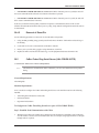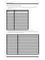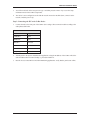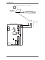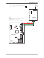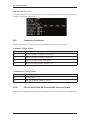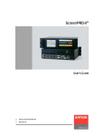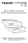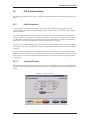
1
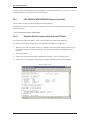
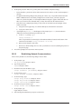
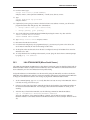
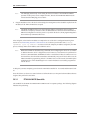
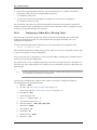
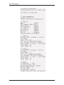
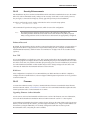
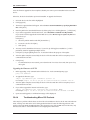
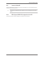
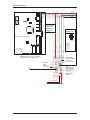
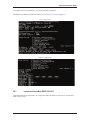
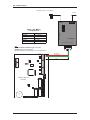
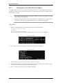
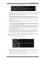
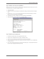
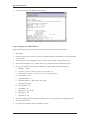
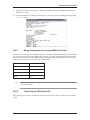
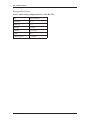
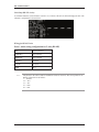
Hardware Installation Guide
30
ISC Communication
The following information can be used to configure communication for Lenel controllers unless otherwise
stated.
30.1
LAN Connections
For LAN panels, any baud rate set on an ISC (LNL-500, 1000, or 2000 primary path (port 1) via DIP
switches 6 and 7) will work as long as the baud rate on the Lantronix box is set to match (via the “change
speed” command).
The primary path of the LNL-2000 connected to a Lantronix box can have its baud rate set to the highest
(115,200) baud rate. The Lantronix box simply needs to have its serial speed at 115,200 as well. In order for
115,200 baud to work reliably on any connection (direct serial, dedicated LAN, or dial-up on a dedicated
phone line), a wire from CTS to RTS1/R1+ on the LNL-2000 Port 1 is required.
The speed of the secondary path (port 6) on the LNL-2000 is always 38400 baud. This is not configurable at
the hardware level. Also, the MSSLITE currently only supports 38400 baud with the LNL-2000, regardless
of the port.
For UL Certified installations, these communication devices, if not directly powered and mounted to the
controller, must be mounted in their own CTX enclosures for their own unique applications unless otherwise
noted. The power for the LAN connection hardware must be provided by the control power supply (LNLAL400ULX).
30.1.1
Lantronix Devices
The EZWebCon management utility software may be used to configure Lantronix devices and update their
firmware. Instead of entering commands at the Local prompt, configuration can be done through on-screen
menus.
EZWebCon configuration wizard
revision 1 — 143
ISC Communications
The latest version of EZWebCon can be downloaded from the Lantronix website (www.lantronix.com). For
detailed information, refer to the Lantronix documentation.
30.2
LNL-ETHLAN (MSS1/MSS100 Ethernet Controller)
This procedure can also be used for the MSS-VIA network adapter.
This Ethernet controller is a network device, and not a part of the UL certification. This device must have
transient protection.
(A NULL MODEM CABLE IS REQUIRED)
30.2.1
Establish Serial Communication with the ETHLAN
The controller-to-MSS100 or MSS1-T cable is now available, part number HOC-ETHLAN.
UL requirement: this device must be on the recommended UPS (#HO2070) or equivalent
1.
With the power OFF to the ETHLAN devices, establish a serial connection from the ETHLAN to the
PC’s Serial Communication Port, for example, using the HyperTerminal. (A Null Modem cable is
required).
2.
Start HyperTerminal.
3.
Change the Communication settings to 9600 Baud, 8 data bits, 1 stop bit, and Parity None.
4.
Plug in power to the ETHLAN. The following messages should appear in the terminal window.
Lantronix Telnet session
144 — revision 1
Hardware Installation Guide
5.
At this point, press the <Enter> key. (It may take a few seconds to complete booting).
•
Power should be cycled to the device while connected to it in order to see the “Load Completed...”
message.
•
If it appears that nothing changes after pressing the <Enter> key, it is possible that the Lantronix
MSS1 or MSS100 device was already configured once. If this occurs, you need to press the
<Enter> key before the phrase, “Load Completed-Boot in Progress” appears. If this still does not
allow you to enter into the command mode, you may also telnet into the Lantronix device.
•
If the device was configured previously, it may be best to do a hard reset and configure it from
scratch. To do this:
•
a.
Using the end of a paper clip, or a similar small object, hold down the reset button.
b.
Cycle power to the device.
A prompt that says Local_1> should appear. If the prompt says Boot>, then the Ethernet
Address has not been defined and you must enter one.
a.
At the Boot> prompt, type:
change hardware n
where n represents the last three digits of the Ethernet Address located on the bottom of the
Lantronix box (Example: change hardware 21-01-65).
6.
b.
Reboot for the change to take effect.
c.
Wait for it to finish loading. Once it’s done, you should see a screen resembling the picture on
the previous page.
You will be prompted for a user name. Enter any name.
30.2.2
Establishing Network Communications
After a factory default reset, the following changes must be made:
1.
At the prompt, type:
set privileged and press <Enter>.
2.
Type in the password:
system and press <Enter>.
3.
Determine and set the IP address. Type:
change ipaddress [IP ADDRESS] and press <Enter>.
4.
Set the Gateway. Type:
change gateway [GATEWAY] and press <Enter>.
5.
Set the boot flags. Type:
change bootp disabled and press <Enter>
change dhcp disabled and press <Enter>
change rarp disabled and press <Enter>
6.
Set the access type to remote. Type:
change access remote and press <Enter>
7.
At the prompt, type:
logout and press <Enter>.
8.
Exit from HyperTerminal and cycle power to the device.
revision 1 — 145
ISC Communications
30.2.3
Configuring the ETHLAN
Any additional changes specific to the hardware that the Lantronix box is connecting to should be made
now. These may include, but are not limited to, baud rate, parity, stop bit, byte size, and flow control.
1.
Make sure the device is powered, completely booted, and connected to the network. Start
HyperTerminal.
2.
You will be prompted for a session name. Enter a name of your choice.
3.
Connect to the device using the IP address, port address of 7000.
4.
A HyperTerminal session starts. Type:
access
and press <Enter>. The access command will not echo.
5.
You will be prompted for a user name. Enter any name. There should be a command prompt.
6.
Type:
set privileged
and press <Enter>.
7.
The password prompt will appear. The password is system.
8.
For baud rate, type:
change speed [SPEED]
and press <Enter> where [SPEED] = the baud rate (9600, 2400, etc.)
9.
For parity, type:
change parity [PARITY]
and press <Enter>, where [PARITY] = none, even, odd, mark, or space.
10. For stop bits, type:
change stopbits [BITS]
and press <Enter>, where [BITS] = 0, 1, or 2.
11. For byte size, type:
change charsize [SIZE]
and press <Enter>, where [SIZE] = 7 or 8.
146 — revision 1
Hardware Installation Guide
12. For flow control, type:
change flow control [FLOW CONTROL]
and press <Enter>, where [FLOW CONTROL] = xonoff, ctsrts, slowcts, or none.
13. Type
change dedicated tcp port=3001
and press <Enter>.
14. (Optional) If you are going to connect to the device from across subnets or routers, you will need to
program the subnet mask and gateway. The commands are:
•
change subnet mask [your subnet mask]
•
change gateway [your gateway]
15. Type in the following to disable BOOT and RARP, depressing the <Enter> key after each line.
LOCAL>>CHANGE BOOTP DISABLE
LOCAL>>CHANGE RARP DISABLE
16. Type change access remote and press <Enter>.
17. Disconnect from the device and exit.
18. If a subnet mask and gateway was programmed (step 9), you must recycle power to the device (the
device must be rebooted) in order for the settings to take effect.
19. At this point, make sure that switch 5 on the ISC is configured correctly for hardware flow control. It
should be set to “ON.”
20. To verify that the device is talking on the network you can “ping” the device from a command prompt
by typing ping <IP address>.
30.3
LNL-ETHLAN-MICR (Micro Serial Server)
The ETHLAN-LITE/ETHLAN-MICR device plugs directly into the ISC panel. It should be labeled with its
Ethernet/hardware address (example: 00-80-a3-2b-02-3b). Note: This method of communication has NOT
been evaluated by UL for Lenel OnGuard UL1076 product listing.
Assign this address to a TCP/IP address over the network by using the ARP utility. In order to do this, the
ARP table on the Windows PC must have at least one IP address other than its own defined. If the ARP table
is empty, the command will return an error message saying that the ARP table addition failed.
1.
At the command prompt, type ARP-A to verify that there is at least one entry in the ARP table. If there
is at least one entry, proceed to step #3.
2.
If there is no other entry listed in the ARP table besides the local machine, ping another IP machine on
the network to build the ARP table. You must ping a host other than the machine on which you are
working.
3.
After the entry is listed in the ARP table, use the following command to ARP the IP address:
arp -s <IP Address> <Ethernet/Hardware Address>
where the <IP address> is the numerical address (example: 192.168.002.203) and the <Ethernet/
Hardware Address> is the address labeled on the Micro Serial Server device (example: 00-80-a3-2b-023b).
revision 1 — 147
ISC Communications
Note:
4.
The ARP/ping method only works during the first two minutes of LNL-ETHLAN-MICR
operation. If this process is not completed in time, then the LNL-ETHLAN-MICR must be
rebooted and the ARP/ping process redone.
Ping the IP address to have the device acknowledge the IP assignment. There should be replies from the
IP address if the ARP command was accepted.
Note:
The ETHLAN-MICR will not save this learned IP address permanently; this procedure is
intended as a temporary measure to allow an administrator to Telnet into the LNL-ETHLANMICR for configuration. Once the power is recycled on the device, the IP programming that is
done with the arp command will be lost.
After doing this, telnet into the IP address to complete the rest of the device configuration starting from
Section 30.2.2, Establishing Network Communications. It is critical to perform line item 3 (change
ipaddress <your ip address> in order to lock in the temporary IP address assigned by the ARP
process. This step makes the IP address static within the device.
Note:
BOOTP and RARP are disabled using commands when configuring the device for use. DHCP
is disabled when the device is shipped from Lenel. However, if an NVR reset is performed on
the device, DHCP, BOOTP, and RARP will all be re-enabled and if there is a DHCP server on
the network the unit will obtain an IP address automatically and you will not be able to use the
ARP command for programming. If there is no DHCP server on the network, the DHCP option
within the device will be disabled again once a static IP address is successfully programmed
into the device.
At this point you must completely power down the LNL-2000 controller for 15 seconds and then turn it back
on.
Once this is done, use the access control software to define the ISC as a LAN panel at the IP address that was
assigned. The panel will come online.
30.3.1
ETHLAN-MICR Standoffs
The standoffs for the ETHLAN-LITE/ETHLAN-MICR come in a separate package. The following diagram
illustrates the positioning.
148 — revision 1
Hardware Installation Guide
Richco plastic P/N LMSP-7-01
Standoffs for ETHLAN
LITE to ISC
INSERT
STANDOFFS
HERE
DO NOT DISPOSE
[Qty 3]
30.4
CoBox Micro 100
The CoBox Micro 100 device plugs directly into the LNL-2000 or the LNL-500 ISC. Jumper J13 must be in
the OFF position for the device to communicate on the LNL-500 and jumper J26 must be in the OFF
position for the device to communicate with the LNL-2000. If it is not in the OFF position, the ISC will be
unable to detect the CoBox Micro 100. The jumper should be ON for all other communications methods.
It should be labeled with its Ethernet/hardware address (example: 00-20-4a-2b-02-3b).
The CoBox Micro 100 can communicate on a 10/100 base-T network.
This method of communication has NOT been evaluated by UL for Lenel OnGuard UL1076 product listing.
Assign a TCP/IP address over the network by using the ARP utility. In order to do this, the ARP table on the
Windows PC must have at least one IP address other than its own defined. If the ARP table is empty, the
command will return an error message saying that the ARP table addition failed.
1.
At the command prompt, type ARP-A to verify that there is at least one entry in the ARP table. If there
is at least one entry, proceed to step #3.
2.
If there is no other entry listed in the ARP table besides the local machine, ping another IP machine on
the network to build the ARP table. You must ping a host other than the machine on which you are
working.
3.
After the entry is listed in the ARP table, use the following command to ARP the IP address:
arp -s <IP Address> <Ethernet/Hardware Address>
where the <IP address> is the numerical address (example: 192.168.002.203) and the <Ethernet/
Hardware Address> is the address labeled on the Micro Serial Server device (example: 00-20-4a -2b02-3b).
revision 1 — 149
ISC Communications
4.
Telnet to the assigned IP address and port 1, this should fail quickly (2-3 seconds). This will force
CoBox Micro 100 to take the new assign IP address temporary.
i.e.) TELNET 192.168.2.203 1
5.
You now need to Telnet into the IP address to complete the rest of the device configuration.
i.e.) TELNET 192.168.2.203 9999
The CoBox Micro 100 will not save this learned IP address permanently; this procedure is intended as a
temporary measure to allow an administrator to Telnet into the CoBox Micro 100 for configuration. Steps 4
and 5 have to be preformed quickly after each other.
30.4.1
Configuring a CoBox Micro 100 using Telnet
The Cobox Micro 100 can be configured via Telnet or Lantronix's DeviceInstaller. The recommended
method for configuration is Telnet. For more information about using DeviceInstaller, refer to the
manufacturer documentation.
From the command prompt, type the following to enter the CoBox Micro 100 configuration menu:
telnet <IP Address> 9999
This command will open the IP Address using port 9999, which is reserved for configuration. Once the port
is open, choose option 0 for Server configuration.
Once you are in the server configuration, you can set up the IP address, default gateway, and subnet mask to
match your specific network configuration.
You will also need to enter a configuration password for the device. The password can be a maximum of 4
characters only, unless enhanced password is enabled. For more information, refer to the CoBox Micro 100
documentation.
Note:
Lenel recommends that you increase the security by enabling enhanced passwords. This allows
for a maximum of 16 characters in the password.
After the Server configuration is complete, choose option 1 for Channel 1 configuration. Make the
following changes in the configuration menu:
a.
Baud rate = 38400
b.
I/F mode = 4C. See Common I/F Mode Valueson page 176.
c.
Flow Control = 02. See Common Flow Control Valueson page 176.
d.
Port Number = 3001
e.
Connection Mode = C0
f.
Send ‘+++’ in Modem Mode = Y
g.
Auto Increment Source Port = N
h.
Remote IP Address = (000). (000). (000). (000)
i.
Remote Port = 00000
j.
DisConnMode = 00
k.
Flush Mode = 00
l.
Disconnect Time = 00:00
m. Send Char 1 = 00
150 — revision 1
Hardware Installation Guide
n.
Send Char 2 = 00
When these changes have been made, type ‘9’ at the main screen to save the changes and exit. The changes
will be stored in the CoBox Micro 100 and the connection will be terminated.
To verify that the changes were stored correctly, cycle the power on the CoBox Micro 100 and when it has
rebooted, go to the command prompt and Telnet to the IP Address that was just given to the device and port
9999 (example: TELNET 192.168.2.203 9999).
The configuration page will display a summary of current settings. Verify that all settings are configured
properly and exit the Telnet session.
revision 1 — 151
ISC Communications
152 — revision 1
Hardware Installation Guide
30.4.2
Security Enhancements
Past installations may have contained vulnerabilities which could lead to unauthorized access to the CoBox
Micro 100. The recommended security settings are not necessary for the unit to work correctly; however,
they are highly recommended to bridge any security gaps left open from previous installations.
In order to configure the security settings, telnet into the unit to access the setup options:
telnet <IP Address> 9999
This command will open the unit using port 9999, which is reserved for configuration.
Note:
Beyond securing the following internal settings of the Lantronix CoBox Micro 100,
networking firewalls should be used to mask services that should not be publicly exposed.
Many security problems can be avoided if servers and networks are appropriately configured.
Enhanced Password
By default, the Cobox Micro 100 does not have a password assigned. In Server Options, you may assign a 4digit password. While a 4-digit password is a step toward securing the unit, it is highly recommended to
enable Enhanced Passwords, which will allow for a maximum of 16 digits. This can be set under Security
(option 6).
Port 77FE
It is recommended that you disable port 77FE. This is an IP port that allows DeviceInstaller, Web-Manager,
and custom programs to configure the unit remotely. Disabling this port prevents unauthorized access to this
unit. If this is not done, it is possible to find this open port using a port scan tool. In addition, any networked
user who installs DeviceInstaller on their machine may be able to change settings to the unit. Note: Port
77FE must be enabled for DeviceInstaller Software to detect the unit.
Web Server
After configuration is completed, it is recommended that you disable Web Server. While it is helpful to
configure the unit via the Web Server, it does not support enhanced password protection. So it is a good idea
to turn this feature off.
30.4.3
Firmware
To ensure that enhanced security is in place, download the latest firmware. Download the latest firmware
from the Lantronix website, www.lantronix.com. There are two recommended methods to update the unit’s
internal operational code: via DeviceInstaller or via TFTP.
Upgrading Firmware via DeviceInstaller
Use the correct version of DeviceInstaller with the correct version of the firmware. For more information,
refer to the DeviceInstaller documentation. Microsoft .NET Framework version 1.1 is also required.
Upon running DeviceInstaller, the software searches for any devices on the LAN. If there are devices present
but they are not detected by the software, you must assign an IP address to it. Assign a TCP/IP address over
the network by using the ARP utility. If it is already configured but still does not show up in the
DeviceInstaller search, verify that port 77FE is enabled.
revision 1 — 153
ISC Communications
After the firmware upgrade has been completed, disable port 77FE to prevent unauthorized access to this
device.
Otherwise, the device should show up in DeviceInstaller. To upgrade the firmware:
1.
Select the device. The line will be highlighted.
2.
Click [Upgrade].
3.
The Device Upgrade Wizard will appear. Select Create a custom installation by specifying individual
files. Click [Next].
4.
Enter the path for the downloaded firmware by either typing it in or clicking [Browse...]. Click [Next].
5.
If you wish to upgrade the internal Web Server, select Install files contained in COB partitions.
If you do NOT wish to upgrade the internal Web Server, select Do not copy or replace any files and
proceed to step 6.
Click [Next].
a.
Select the partition number and click [Set Partition...].
b.
Locate the .cob file. Click [OK].
c.
Click [Next].
6.
You may save this installation for later use, if you wish, by clicking [Save Installation...]. This is
particularly useful for upgrading multiple devices.
7.
Click [Next] to begin updating the device. A status bar indicates the progress of the update.
8.
After the update completes successfully, the device will reboot and there will be a temporary loss of
communication to the ISC.
9.
Click [Close].
•
If communications are not restored, power down the ISC for at least 10 seconds, then power it up
once again.
Upgrading the Firmware via TFTP
1.
Before upgrading, verify communication with the device. At the command prompt, type:
ping <IP address>
2.
To upgrade the firmware, type:
tftp-i <ip address> put <firmware source> 3L
For example: tftp-i 10.112.5.92 put d:\lantronix\micro\ltx5801.rom 3L
3.
After the update completes successfully, the device will reboot and there will be a temporary loss of
communication to the ISC.
4.
If you wish to upgrade the internal web interface, type:
tftp-i <ip address> put <internal web interface> WEB6
For example: tftp-i 10.112.5.92 put d:\lantronix\micro\cbx360.cob WEB6
5.
Upon successful upgrade, a confirmation message will be displayed.
30.4.4
Troubleshooting Micro 100 Products
There may be a problem with the latest version of the on-board Ethernet devices for the LNL-500 and LNL2000. A change was made to the device during production that will cause the following problems. This
applies to the LNL-ETHLAN-MICR ONLY. It does not apply to the older 10 MB version of the units, only
the latest units that are 10/100 MB and have been shipping since March 2004.
154 — revision 1
Hardware Installation Guide
• LNL-ETHLAN-MICR with firmware version 5.4 If Micro-100 unit's power is cycled,the unit will
not restore communications unless the reset button on the Micro is pressed.
• LNL-ETHLAN-MICR with firmware version 5.5 If Micro-100 unit's power is cycled, the unit will
fail to restore communications 1/20 times.
In all cases, Lantronix and our Quality Assurance Group have confirmed that removal of Pin 10 will
eliminate all communication failures due to power cycling. Setup and unit configuration remain the same as
as documented.
30.4.5
Removal of Reset Pin
Use the following procedure to remove Pin 10 from the Micro 100 product.
1.
Using an ESD grounding strap, ground yourself and remove the Micro 100 from the anti-static bag or
the housing.
2.
Locate Pin 10 of Conn1 on the back side of the Micro 100 unit.
3.
Protect your eyes with safety goggles. Using shearcutters, cut Pin 10.
4.
Replace the Micro 100 into the anti-static bag, or to the equipment that houses the Micro 100.
30.5
CoBox Token Ring Serial Server (LNL-COBOX-201TR)
(A STRAIGHT THROUGH CABLE IS REQUIRED)
Note:
This method of communication NOT evaluated by UL for Lenel OnGuard UL1076 product
listing.
Network Requirements:
Token Ring hub
Machine Requirements:
A PC is needed to configure the CoBox Token Ring Serial Server. The machine must have the following
installed:
•
Token Ring Network Interface Card (NIC)
•
OnGuard Software
•
HyperTerminal Software
To Configure the CoBox Token Ring Serial Server (part # LNL-COBOX-TR201):
Step 1: Establish Serial Communication with CoBox
1.
With the power OFF to the CoBox device and the network disconnected, establish a serial connection
from the CoBox to the PC’s Serial Communication Port, for example, using HyperTerminal. (A straight
through cable is required).
revision 1 — 155
ISC Communications
2.
Start HyperTerminal. The Connection Description window will open with the “New Connection”
setting. (Choose New Connection from the File menu if the Connection Description window does not
open).
3.
In the Name field, type COBOX and click [OK].
4.
Select Direct Connect and choose the COM port to which the cable is connected on the computer.
5.
Change the Communication settings to: 9600 Baud, 8 data bits, 1 stop bit, and No Parity.
6.
Once in Terminal mode, hold down the <x> key on the keyboard and plug in power to the CoBox
device. The following will appear on the screen (version and serial numbers may be different):
7.
Press <Enter> to go into the CoBox device’s setup mode. The CoBox device’s current configuration
will be displayed. It will look similar to the following:
8.
Type 0 and then press the <Enter> key to enter the basic setup for the CoBox device.
9.
Enter the IP address for the CoBox device in the form of 10.11.12.13. The currently configured address
will appear as you get to each part of the IP address as you are typing; just continue to type the new
number.
156 — revision 1
Hardware Installation Guide
10. The software will next ask you if you wish to set the gateway. Answer yes and type the gateway IP
address just as you did for the IP address of the device. As it did for the device’s IP address, the current
configuration information will display at each segment of the IP address.
11. You now need to enter a subnet mask. You CANNOT enter a number here as you are used to, you must
use the following table to determine what to type into this field.
255.255.255.252
=02
255.255.252.0
=10
255.252.0.0
=18
255.255.255.248
=03
255.255.248.0
=11
255.248.0.0
=19
255.255.255.240
=04
255.255.240.0
=12
255.240.0.0
=20
255.255.255.224
=05
255.255.224.0
=13
255.224.0.0
=21
255.255.255.192
=06
255.255.192.0
=14
255.192.0.0
=22
255.255.255.128
=07
255.255.128.0
=15
255.128.0.0
=23
255.255.255.0
=08
255.255.0.0
=16
255.0.0.0
=24
255.255.254.0
=09
255.254.0.0
=17
12. You will be prompted to change the Telnet configuration password. Answer Yes to the prompt.
13. Enter SYST for the password when prompted.
14. When asked to use a token-ring administered address answer NO.
15. You will now be at the setup screen. Make sure the information displayed at the top matched the
information you just typed into the unit.
revision 1 — 157
ISC Communications
Step 2: Entering the Serial Port Setup Menu
1.
Type 1 and then press the <Enter> key to enter the serial port setup menu. For each item, enter the
following value:
Item
Value
Baud rate
38400
I/F mode
4C
Flow control
00
Port #
03002
Connect mode
C1
Remote IP address
0.0.0.0
Remote port
00000
Disconnect mode
00
Flush mode
11
Disconnect time
00:00
Send char 1
00
Send char 2
00
Information is available for hexidecimal values. See Commonly Used Valueson page 176.
2.
You will now be back at the setup screen. Type 2 and then press the <Enter> key to enter the serial port
setup menu. For each item, enter the following value.
Item
Value
Baud rate
38400
I/F mode
4C
Flow control
00
Port #
03001
Connect mode
C1
Remote IP address
0.0.0.0
Remote port
00000
Disconnect mode
00
Flush mode
11
Disconnect time
00:00
Send char 1
00
Send char 2
00
158 — revision 1
Hardware Installation Guide
3.
You will now be back at the setup screen. Type 9 and then press the <Enter> key to save the setup
information and exit the CoBox setup menus.
4.
The device is now configured to work with the network. Power the machine down, connect it to the
network, and then power it up.
Step 3: Connecting the ISC to the CoBox Device
1.
Connect the ISC to the CH2 port of the CoBox device using a direct connection cable according to the
cable pinout table below.
Cable Pinouts
ISC
9-pin female
TXD/TR1+
pin 2
RXD/TR1-
pin 3
RTS/R1+
not used
CTS/R1-
pin 7
GND
pin 5
Jumper together
4,6 & 8
2.
Add the panel in the System Administration application, using the IP address of the CoBox. This is the
same IP address that was entered in Step 1, procedure number 10.
3.
Run the Access Control Driver and Alarm Monitoring applications. Verify that the panel came online.
revision 1 — 159
ISC Communications
ISC to Lantronix CoBox Token Ring Serial Server Configuration
15V Power
Supply
CoBox Token Ring
Serial Server
TOKEN RING NETWORK
(COBOX-TR201)
DI
RE
CT
C
ON
NE
CT
IO
N
CA
BL
E
CH 2
9-pin female
2
TXD
TR1+
RX
D
TR1-
J12
J11
J10
Intelligent System Controller
RTS
R1+
CTS
R1-
J13
ACD
C
A
C
GND
IN
2
not used
GND
TR2+
J7
TR2-
J9
J14
GND
2W 4W
232 485
J8
GND
J15
J1
A
GND
IN
1
B
TR3+
C
TR3GND
J16
TR4+
TR4GND
J17
TR5+
TR5GND
1 2 3 4 5 6 7 8
J18
S1
J5
J
3J
2J
4
U15
J6
2 MEG
U17
LITHIUM
3V
BR2325
P
N
160 — revision 1
RE
V
S
N
U16
3
5
7
Jumper together
4, 6 & 8
Hardware Installation Guide
30.6
Lantronix CoBox-DR
The ISC can alternatively be connected to the Lantronix CoBox-DR unit. Use the following information to
set up the CoBox-DR unit and the ISC.
Note:
30.6.1
This method of communication NOT evaluated by UL for Lenel OnGuard UL1076 product
listing.
DSTni-Xpress DR RS-232 Configuration for the ISC
Connection to the ISC can either be through screw terminals or RJ-45 serial port.
revision 1 — 161
ISC Communications
J11
J10
J13
J1 2
ACDC
J8
GND
TXD
CTS
RTS
GND
TR2+
J7
TR2-
J9
J14
GND
2W 4 W
2 32 4 85
AC
Pin 3
Pin 4
Pin 6
Pin 7
Pin 5
RXD
TXD
TR1+
RXD
TR1RTS
R1+
CTS
R1GND
485 232
GND
J15
IN2
J1
GND
A
B
TR3+
C
TR3-
IN1
GND
J16
TR4+
TR4GND
J17
TR5+
TR5GND
Serial RJ-45
1 2 3 4 5 6 7 8
J18
For RS-232
Communication,
Dip Switch 5
must be set to
ON position
S1
1
J5
Intelligent System Controller (ISC)
U15
8
View from
Connector End
128K
J3
J2
J4
512K
1. NC
2. DTR(OUT)
3. RXD(IN)
4. TXD(OUT)
5. GND
6. CTS(IN)
7. RTS(OUT)
8. NC
REV
SN
RTS
PN
RXD
LITHIUM
3V
BR2325
GND
U16
CTS
U17
T XD
J6
2 MEG
For RS-232 communication, jumpers must be
configured properly. Refer to Hardware
Installation guide for specific ISC.
RJ 45 Serial Port
RS-232 & RS-422/485
~
RJ Ethernet Port
To 10/100 Base T Network
12VDC Negative
12VDC Positive
162 — revision 1
Hardware Installation Guide
To configure the server and channel 1, refer to the following screenshots.
Information is available for hexidecimal values. See Commonly Used Valueson page 176.
Server configuration
Channel 1 configuration
30.7
Lantronix SecureBox SDS1100/1101
Connect the SDS device with an ISC. As of September 2005, the firmware version is 5.6, with an AES
library version 1.8.2.1.
revision 1 — 163
ISC Communications
SDS1100 to ISC, 2-wire RS-485
To LAN
9-30VDC
10/100
Ports 1 & 6 Wiring
Configuration
SDS1100
ISC
TXD/TR1+
RXD/TR1RTS/R1+
CTS/R1GND
25-Pin Connector
Pin 14 and 21
Pin 15 and 22
Not Used
Not Used
Pin 7
Lantronix
25 -Pin Fem ale Serial Connector
ISC:
Communications Interface Type = RS-485
RS-485 Type = 2-W ire RS-485
(Refer to the ISC documentation for more information )
485 232
J10
TX D
TR 1+
A CDC
R TS
R 1+
C TS
R 1-
J1 3
J12
J11
RX D
TR 1-
GN D
Pin 7
GN D
TR 2+
J7
TR 2-
J9
J 14
GN D
2W 4W
232 48 5
J8
AC
GN D
J 15
I N2
J1
GN D
A
B
TR 3+
C
TR 3-
I N1
GN D
J 16
TR 4+
TR 4GN D
J 17
TR 5+
TR 5GN D
1 2 3 4 5 6 7 8
J 18
S1
Intelligent System
C ontroller
J5
J2
J4
2 M EG
J6
J3
U 15
U 17
LI TH I U M
3V
B R 2325
PN
164 — revision 1
RE V
SN
U 16
Pin 14 & 21
Pin 15 & 22
Hardware Installation Guide
SDS1100 to ISC, 4-wire RS-485
To LAN
9-30VDC
10/100
Ports 1 & 6 Wiring
Configuration
25-Pin Connector
Pin 2
Pin 3
Not Used
Pins 4 & 5
Pin 7
6,8 & 20
SDS1100
ISC
TXD/TR1+
RXD/TR1RTS/R1+
CTS/R1GND
Jumper Together
Lantronix
25 -Pin Female Serial Connector
ISC:
Communications Interface Type = RS-232
RS-232 Type = 4-W ire RS-232
(Refer to the ISC documentation for more information )
RX D
TR 1-
J1 1
J 10
2W 4W
232 48 5
J8
AC
GN D
GN D
Pin 7
TR 2+
J7
TR 2-
J9
J14
GN D
Pin 3
Pin 4 & 5
R TS
R 1+
C TS
R 1-
J13
J 12
A CDC
Pin 2
TX D
TR 1+
485 232
GN D
J 15
I N2
J1
GN D
A
B
TR 3+
C
TR 3-
I N1
GN D
J 16
TR 4+
TR 4GN D
J 17
TR 5+
TR 5GN D
1 2 3 4 5 6 7 8
J 18
S1
Intelligent System
Controller
J5
J3
J2
J4
U 15
J6
2 M EG
U 17
U 16
LI TH I U M
3V
B R 2325
PN
RE V
SN
revision 1 — 165
ISC Communications
30.7.1
Configuration of the SDS1100/1101/CoBox-FL
To configure this Lantronix device, perform the following procedures. You may configure through a telnet
connection over the network, or a terminal program over a serial connection. For more information, refer to
the Lantronix User Guide.
Notes:
These instructions also apply for the CoBox-FL, with the exception of encryption. Encryption
is not available on the CoBox-FL.
Encryption using the Lantronix SDS is supported only for third-party devices, and not Lenel
access panels. Ensure that encryption is turned off for use with Lenel access panels.
Using Telnet
1.
From the command prompt, type the following to enter the configuration menu:
telnet <IP Address> 9999
Or, in Unix:
telnet <IP Address>:9999
This command will open the IP Address using port 9999, which is reserved for configuration.
Lantronix SDS settings
2.
Press <Enter> to go into the setup mode. The Change Setup menu is displayed.
Change Setup menu
3.
Type the number of the option you would like to access. Press <Enter>.
4.
Select the option which you would like to change and type in the new value. If you would like to just
confirm the current setting, do not type anything. Press <Enter>.
5.
Select 0 for Server, the device’s current settings are displayed.
166 — revision 1
Hardware Installation Guide
Server configuration
a.
IP Address. If DHCP is not used to assign IP addresses, enter the IP address manually. The IP
address must be set to a unique value in the network. Enter each octet and press <Enter> between
each section. The current value displays in parentheses.
b.
Gateway IP Address. The gateway address, or router, allows communication to other LAN
segments. The gateway address should be the IP address of the router connected to the same LAN
segment as the unit. The gateway address must be within the local network. The default setting is N
(No), meaning the gateway address has not been set. To set the gateway address, type Y and enter
the address.
c.
Netmask: Number of Bits for Host Part. A netmask defines the number of bits taken from the IP
address that are assigned for the host part.
Note:
Class A: 24 bits; Class B: 16 bits; Class C: 8 bits
The unit prompts for the number of host bits to be entered, then calculates the netmask, which
appears in standard decimal-dot notation (for example, 255.255.255.0) when the saved parameters
are shown. The default setting is 0.
d.
6.
Change telnet config password. Setting the telnet configuration password prevents unauthorized
access to the setup menu through a telnet connection to port 9999 or through web pages. The
password must have four characters. The default setting is N (No). (You do not need a password to
access the Setup Mode window by a serial connection.) This setting is optional.
You will need to configure the serial port to communicate with the third party hardware devices. (Some
of the characters need to be entered in hexadecimal notation.) Select 1 for Channel 1 define how the
serial port responds to network and serial communications.
Channel 1 configuration
a.
Baudrate. The unit and attached serial device, such as a modem, must have matching speed or
baud rates to use for the serial connection. Valid baud rates are 300, 600, 1200, 2400, 4800, 9600
(default), 19200, 38400, 57600, 115200, and 230400 baud.
b.
I/F Mode. The Interface (I/F) Mode is a bit-coded byte entered in hexadecimal notation. The
default setting is 4C. See Common I/F Mode Valueson page 176.
revision 1 — 167
ISC Communications
c.
Flow. Flow control sets the local handshaking method for stopping serial input/output. The default
setting is 00. See Common Flow Control Valueson page 176.
d.
Port No. The port number setting represents the source port number in TCP connections. It is the
number that identifies the channel for remote initiating connections. The default is port 10001. The
range is 1-65535. This should always be set to 3001 in order to communicate with third party
hardware devices.
e.
Connect Mode. Connect Mode defines how the unit makes a connection, and how it reacts to
incoming connections over the network. The default setting is C0 and should be used to
communicate with third party hardware devices.
The following may be left at default settings:
7.
f.
Remote IP Address.
g.
Remote Port.
h.
DosConnMode.
i.
FlushMode.
j.
DisConnTime.
k.
SendChar 1.
l.
SendChar 2.
When the configuration is complete, type 9 in the Change Setup menu to save your settings and exit.
The device will reboot. Or, to exit without saving any of your changes, type 8.
Using a Terminal Program
Use a terminal program to configure the device through a serial connection.
1.
Connect the device to a console terminal or PC running a terminal emulation program using the serial
port. The default serial port settings are 9600 baud, 8 bits, no parity, 1 stop bit, no flow control.
2.
Reset the device by cycling the unit's power (turning the power off and back on). Immediately upon
resetting the device, type xxx.
Note:
3.
The easiest way to enter Setup Mode is to hold down the x key at the terminal (or emulation)
while resetting the unit. You must do this within three seconds of resetting the device.
At this point, the screen display is the same as a telnet connection. To continue, go to step 2 under Using
Telnet.
30.8
Note:
Lantronix UDS-10/UDS100/UDS200/UDS1100
This method of communication NOT evaluated by UL for Lenel OnGuard UL1076 product
listing.
168 — revision 1
Hardware Installation Guide
Step 1: Establish a serial connection with ETHLAN
With the power OFF on the UDS device, establish a serial communication from the UDS to the PC’s serial
communication port, for example, using HyperTerminal.
1.
Start HyperTerminal.
2.
Select the correct PC port and change the communication settings to 9600 baud, 8 data bit, and parity
none.
3.
Hold down the <X> key on your keyboard and plug the power back into the UDS device. This will
allow you to enter the setup mode on the ETHLAN.
4.
At this point, type <Enter>, and follow the onscreen instructions for programming.
5.
When prompted for a password, please use UDS and press <Enter>.
Step 2: Establish network communication
1.
Determine the IP address that will be programmed into the UDS.
2.
Enter the Server Configuration menu by typing 0 and hitting <Enter>.
3.
Follow the onscreen instructions and enter all your necessary network settings.
4.
Refer to the manufacturer manual when entering the subnet mask information. Note: for standard class
C subnet, enter an 8.
5.
Once you have finished entering all your custom network settings, type a 9 at the prompt. This will save
all your network configurations and reboot the UDS.
revision 1 — 169
ISC Communications
6.
You can close your current HyperTerminal session.
Step 3: Configure the UDS ETHLAN
Make sure that the device is powered up, completely booted, and connected to the Network.
1.
Start Telnet.
2.
From the connect menu, connect to the device using the IP address, Port address of 9999, and terminal
type of VT100.
3.
You will see the same configuration screen as before, now hit <Enter> and go into the setup.
4.
At the selections prompt, type 1 and hit <Enter> to go into the Channel Configurations menu.
5.
Once you are in the setup for channel 1 configuration, please make the following changes:
a.
Baud rate = 38400
b.
I/F mode = 4C. See Common I/F Mode Valueson page 176.
c.
Flow Control = 02. See Common Flow Control Valueson page 176.
d.
Port Number = 3001
e.
Connection Mode = C0
f.
Remote IP Address = (000). (000). (000). (000)
g.
Remote Port = 00000
h.
DisConnMode = 00
i.
Flush Mode = 00
j.
Disconnect Time = 00:00
k.
Send Char 1 = 00
l.
Send Char 2 = 00
6.
Once these settings have been properly configured, enter 9 at the prompt to save changes and exit.
7.
Close the Telnet session.
8.
Cycle the power manually on the UDS and let it reboot.
170 — revision 1
Hardware Installation Guide
9.
At this point, make sure that switch 5 on the ISC is configured correctly for hardware flow control. It
should be set to “ON.”
10. To verify that the device is talking on the network you can “ping” from the command prompt by typing
ping IP address.
30.8.1
Wiring Configuration for Custom DB25 Serial Cable
The cable for the UDS must be a straight through cable. The Other LANTRONIX devices, such as the MSS100, require a null cable for serial communication to the ISC. The cable is also different because the MSS100 uses a serial cable with a female DB25 connector. The UDS custom cable must have a male connector
because the fixed serial port on the device has a female adapter.
TXD
Pin 2
RXD
Pin 3
RTS
Pin 4
CTS
Pin 5
GND
Pin 7
Note:
30.8.2
Refer to the manufacturer installation manual for more information on the custom cable and
pin out information.
Connecting the UDS with an ISC
These units operate on 10-base T. Make sure that if connected to a hub, that it is 10 base T or auto-sensing
10/100.
revision 1 — 171
ISC Communications
Wiring for RS-232 4-wire.
Ports 1 and 6 wiring configuration for 4-wire (RS-232)
ISC
25-pin connector
TXD/TR1+
Pin 2
RXD/TR1-
Pin 3
RTS/R1+
Not used
CTS/R1-
Pins 4 and 5
GND
Pin 7
Jumper together
6, 8, and 20
172 — revision 1
Hardware Installation Guide
To LAN
Configuring UDS-10 to ISC 4-Wire (232)
6 VDC
UDS-10
ISC:
Communications Interface Type = RS-232
RS-232 Type = 4-Wire RS-232
(Refer to ISC documentation for more information )
RX D
TR1-
J1 1
J10
RTS
R1+
CTS
R1-
J13
J12
A CDC
AC
GND
Pin 7
TR2+
J7
25-Pin Female Serial Connector
Pin 4 & 5
GND
TR2-
J9
J14
GND
2W 4W
232 48 5
J8
Lantronix
Pin 2
Pin 3
TX D
TR1+
485 232
10 Base T
GND
J 15
I N2
J1
GND
A
B
TR3+
C
TR3-
I N1
GND
J 16
TR4+
TR4GND
J 17
TR5+
TR5GND
1 2 3 4 5 6 7 8
J 18
S1
Intelligent System
Controller (1000 )
J5
J3
J2
J4
U15
J6
2 M EG
U17
U16
LI THI UM
3V
B R2325
PN
RE V
SN
revision 1 — 173
ISC Communications
Unit Setup (RS-232 4-wire)
As of March 2004, the current firmware version is 4.5. Connect to the unit via Telnet through port 9999. The
Channel 1 configuration is shown below.
Wiring for RS-485 2-wire
Ports 1 and 6 wiring configuration for 2-wire (RS-485)
ISC
25-pin connector
TXD/TR1+
Pins 14 and 21
RXD/TR1-
Pins 15 and 22
RTS/R1+
Not used
CTS/R1-
Not used
GND
Pin 7
Note:
The pinouts in the earlier UDS-10 Installation Guide are incorrect! The correct pinout for an
RS-485 connection are as follows:
7 — Ground
14 — TX+
15 — TX21 — RX+
22 — RX-
174 — revision 1
Hardware Installation Guide
To LAN
Configuring UDS -10 to ISC 2-Wire (485)
6vdc
UDS-10
ISC:
Communications Interface Type = RS-485
RS-485 Type = 2-Wire RS-485
(Refer to ISC documentation for more information )
485 232
J11
J1 3
RTS
R1+
CTS
R1-
2W 4W
232 48 5
GND
Pin 7
GND
TR2+
J7
TR2-
J9
J14
GND
25-Pin Female Serial Connector
Pin 15 & 22
RX D
TR1-
J8
AC
Lantronix
Pin 14 & 21
TX D
TR1+
J10
J12
A CDC
10 Base T
GND
J15
I N2
TR3+
J1
GND
A
B
C
TR3-
I N1
GND
J16
TR4+
TR4GND
J17
TR5+
TR5GND
1 2 3 4 5 6 7 8
J18
S1
Intelligent System
Controller (1000 )
J5
J2
J4
2 M EG
J6
J3
U15
U17
U16
LI THI UM
3V
B R2325
PN
RE V
SN
revision 1 — 175
ISC Communications
Unit Setup (RS-485 2-wire)
As of March 2004, the current firmware version is 4.5. Connect to the unit via Telnet through port 9999. The
Channel 1 configuration is shown below.
30.9
Commonly Used Values
Interface (I/F) mode is a bit-coded byte entered in hexadecimal notation, as is flow control.
Common I/F Mode Values
I/F Mode
Description
F8
RS-232, 2 stop bits, even parity, 7-bit byte size
78
RS-232, 1 stop bit, even parity, 7-bit byte size
4C
RS-232, 1 stop bit, no parity, 8-bit byte size
5C
RS-232, 1 stop bit, odd parity, 8-bit byte size
Common Flow Control Values
Flow Control
Description
00
No flow control
02
Hardware handshake with RTC/CTS lines
30.10
LNL-IC108A/IC109A RS-232 to RS-485 Converter (4-wire)
This method of communication has NOT been evaluated by UL for Lenel OnGuard UL1076 product listing.
176 — revision 1
Hardware Installation Guide
Black Box Settings:
S1
A
A B C
W15
W19
A B C
A B C D E
W8
W16
B C D E
W17
Black Box IC108A
Black Box IC109A
A B C
Jumpers:
W5 - should be on B-C to set RTS/CTS/CD
W8 - should be on A-B to set 4-wire
W9 - should be on D to set ON
W15 - should be on A-B to set RTS/CD Enabled
W16 - should be on A to set 0 ms Turn Around Delay
W17 - should be on E to set 0.15 ms Driver Enable Hold
W19 - NO JUMPER. This is for test purposes only.
XW1A - Jumper-block must be installed here to set DCE
Emulation Mode
XW1B - Jumper-block must NOT be installed here (this
would change mode to DTE Emulation).
W9
A B C D E
Switches:
S1 -Out to set Normal
S2 - ON to set Terminated or OFF to set Not Terminated
S3 - OFF to set Not Biased
W5
A B C
BIAS
TERM.
S3
S2
XW1B
XW1A
ISC:
RxB
RxA
TxB
7
RTS
GND
3
Rx
2
Tx
TR2+
J7
TR2-
J9
J14
GN
D
IN2
2W 4W
GND
J13
J8
232 485
AC
TXD
TR1+
RXD
TR1RTS
R1+
CTS
R1-
J11
J10
J12
ACD
C
25-Pin Serial Connector
TxA
110 VAC
Transformer
Communications Interface Type = RS-485
RS-485 Type = 4-Wire RS-485
Port 1 RS-485 EOL Termination = Termination 'OFF'
(Refer to ISC documentation for more information)
GND
J15
TR3+
J1
GN
D
IN1
A
B
C
TR3GND
J16
TR4+
TR4-
TR1+ TR1- R1+ R1-
GND
J17
TR5+
TR5GND
1 2 345 6 7 8
J18
S1
Intelligent System
Controller
Downstream
ISC on RS485 Line
5
J5
U15
ISC panels can be
multidropped on the RS485 line using this
configuration.
2
3
DB 9 Pin Male
7
3
2
DB 25 Pin Female
J
3
J
2
J
4
9 or 25 Pin Connector
Workstation (PC)
J6
2 MEG
U17
U16
LITHIUM
3V
BR2325
PN
RE
V
SN
revision 1 — 177