1
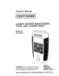
Owner's
Manua
Model No.
320.48251
/k
Z___.w
CAUTION:
Read, understand and
follow all Safety Rules and Operating
Instructions in this manual before using
this product.
, SAFETY
• OPERATION
° MAINTENANCE
"ESPAI_IOL, PAGINA 17
Sears, Roebuck and Co., Hoffman Estates, IL 60179 U.S.A.
Warranty. ............................................................
Page
2
Safety Instructions ...........................................
Description .........................................................
Page
Page
3
4
Operation .......................................................
Maintenance ......................................................
TroubleShooting ................................................
Service Numbers ...............................................
Pages 5 -12
Page 13
Page 14
Back Cover
FULL ONE YEAR WARRANTY
LASER LEVEL
ON CRAFTSMAN
If this CRAFTSMAN
Laser Level fails to give complete satisfaction
within one year from the date of purchase, RETURN IT TO THE
NEAREST SEARS STORE IN THE UNITED STATES, and Sears
will replace it, free of charge.
If this CRAFTSMAN
Laser Level is used for commercial or rental
purposes, this warranty applies for only 90 days from the date
of purchase.
This warranty gives you specific legal rights, and you may also
have other rights which vary from state to state.
Sears,
Roebuck
and Co., Depto 817WA,
SAVETHESE INSTRUCTIONS!
READ ALL INSTRUCTIONSt
2
Hoffman
Estates, IL 60179
j
manual
before using BE
this SURE
level. Failure
all instructions
may result
in
WARNING:
to read to
andfollow
understand
all instructions
in this
radiation exposure, electric shook, fire, and/or bodily injury.
hazardous
IIIII
CAUTION:
procedures
exposure°
I: ............
Use of controls
other than those specified
CAUTION;
or adjustments
or performance
of
herein, may result in hazardous
radiation
The use of optical instruments with this product will increase
eye hazard.
are
on your level.
indicate
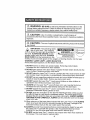
IMPORTANT:
The They
following
labels
LASER RADIATION
{
where the laser light is emitted by
DO NOT STARE INTO REAM
_La_er radJat_(_n_
Is Cmll|_d
the level.. ALWAYS BE AWARE of their
location when using the level ALWAYS
C_s DL_ ,t._:ser Produ¢! CQmpne_
MAKE SURE that any bystanders
in the
.i,,2=c_=o4o._o,._1o,o_
vicinity of use are made aware of the dangers of looking directly into the laser.
WARNING!
LASER LIGI-{T. LASER RADIATION
Avoid Direct Eye Exposure° Do Not Stare into beam_
z_
1. DO NOT remove or deface any product labels. Removing
increases the risk of exposure to laser radiation
product
labels
2. DO NOT stare directly at the laser beam or project the laser beam directly
eyes of others. Serious eye injury could result.
into the
3. DO NOT place the Laser Trac TM Level in a position that may cause anyone to stare
into the laser beam intentionally or unintentionally.
Serious eye injury could result,,
4. DO NOT use any magnifying optical tools such as, but not limited to telescopes
transits to view the laser beam. Serious eye injury could result.
5. DO NOT operate the Laser Trac TM Level around children or allow children to
operate the toolo Serious eye injury could result
6. ALWAYS
increases
turn the Laser Trac
the risk of someone
TM
or
Level off when not in use, Leaving the tool on
inadvertently
staring into the laser beam
7. DO NOT operate the Laser Trac TM Level in combustible
presence of flammable liquids, gasses or dust.
areas such as in the
8. DO NOT push the red buttons on the Thin-Pin Wall Mount Base unless you plan
the affix the base to a soft wood or wallboard surface° This could result in injury,
because the pins under the base are very sharp instruments.
ALWAYS HANDLE
THIS BASE PLATE CAREFULLY.
ALWAYS use the protective cover on the base
when not in use.
9. When using any of the base plates included with the Laser Trac TM Level ALWAYS
check to be sure that the tool is securely mounted on the base. Damage to the
tool and/or serious injury to the user could result if the tool fall&
10. ALWAYS use only the accessories that are recommended
by Sears for use with
the Laser Trac TM Level with this product. Use of accessories that have been
designed for use with other laser tools could result in serious injury°
11. DO NOT use the Laser Trac TM Level for any purpose
this manual This could result in serious injury,.
3
other than those outlined
in
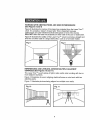
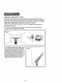
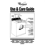
KNOWYOUR LEVEL (See Fig. 1)
This Craftsman Laser Trac TM Level is a highly versatile tool.
tt can be hand-held,
stand_
wall-mounted
or leveled on a horizontal surface or tripod
it projects a laser line that sweeps a full 90 °, horizontal to vertical and all
angles in between.
Performance is further.enhanced
in that with straight-ahead projection it wilt
place the laser line on either side of an obstruction or on multiple surfaces,
This marking and leveling tool is easy to use in many applications from simple
home decorating projects to professionally installed kitchen cabinets.
This Craftsman Laser Trac TM Level is not calibrated as a height-measuring
device and should not be used as such. It wil! give a reference mark when
used as a hand-held or wall-mounted tool.
When leveled on the Precision Leveling Base or used with the Tripod Mount
(both included) it will project a level horizontal or vertical line that is accurate
to ±3/8-inch at 30 feet.
Fig, 1
Laser Light
Level vials
Thin-Pin Walt
Laser Enhancing
Scrolling
'
Knob
Aperture -___ _
Mount Base
Tinted Glasses
Label
Mounting Base
On/off
Switch
Label
Tripod
-_
•_
Preci
Leveling Base "_
i ...................
i,
-
TECHNICAL
SPECIFICATIONS
, ,,,,,,,.....
Recommended
Use
i
, .....
Indoors
Laser Diode Type
Red Laser Diode 650 nm
Laser Class
Class Ilia, maximum
power output _<23 mW
Power Supply
2 "AA" 1.5-volt batteries
,,,,,,,
Estimated
Battery
Life
40 hours of continuous
with alkaline batteries
use
Optimum Operating
Temperature Range
30°F to 104 ° F (-1°C to 40°C)
Accuracy
_+3t8-in.at 30 ft.
,
,,,,,,
.......
4
L.....
,,.....
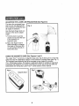
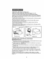
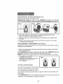
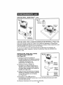
TO INSTALL BATTERIES (See Figures 2 and 3)
This Laser Trac TM Level uses two "AA" batteries,
IMPORTANT: BEFORE installing the batteries, ALWAYS check to be sure that
the on/off switch on the level is in the up off position (see Fig. 2)°
Fig. 2
Fig. 3
up-elf
down-on
,2
1. Turn the black battery cover plate on the back of the level 1/4 turn in a
counterclockwise
direction and remove cover (see Fig. 3).
2, Install the batteries with the polarity as indicated on the label in the battery
compartment,,
3. Place the black cover plate back onto the tool and turn the plate 1/4 turn in a
clockwise direction to lock,
TO TURN THE TOOL ON (See Figure 4)
The switch to turn the Laser Trac TM Level on is located on the front of the toolo
1, Move the switch down to its lowest level to turn on the laser°
z_WARNING:
When turning on the Laser Trac TM Level ALWAYS be aware
of protecting the eyes of yourself and those around you°
NEVER point the Laser Trac TM Level at anyone's face, including your own.
2, To turn tool off, move switch
all the way up until it locks in the up
position,
Fig. 4
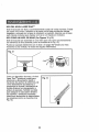
Using the Glasses Included
This level includes a pair of standard
safety glasses that are made of a laser
light enhancing material.
._
The primary purpose of these glasses
is to improve the viewing of the tool's laser lineo
Z_WARNING:
These glasses WILL NOT protect the eyes from damage that
could result from looking directly into the laser projection,
5
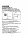
ADJUSTING
THE LASER LINE PROJECTION
The laser line projected from
this tool can be adjusted 90 °
from vertical to horizontal and
all angles in between,
Use the black finger knob on
the top of the tool to adjust
angle,
1. Turn the tool on and be
careful not to point the tool
in the direction of
anyone's eyes.
2. Move the finger knob in
either direction to change
the angle of the laser line
on any surface directly in
front of the tool.
(See Figure 5)
Fig. 5
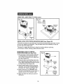
USING THE MAGNETIC BASE (See Figures 6 and 7)
The Laser Trac TM Level has a magnetic base (see Fig. 6) that can be used with
either the Thin-Pin Wall-Mount Base or the Precision Leveling Base (see Fig. 7).
The magnetic base allows the tool to be mounted on any coated or uncoated
13/4x 4-in flat steel surface. This feature is particularly handy for working on steel stud
framework and duct_,_lork.For further instructions on the use of this tool with the
base plates see Using the Laser Trac TM Level section of this manual,
un,, i,lll,ll,,,,H,_,
............
i i,lll,ll
Fig.
Fig. 6
Magnetic
Base
6
i,llL,,, uH,,,,lln,,lll ,i,tl
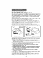
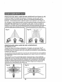
WORKINGWITH OBSTRUCTIONS
AND USER INTERFERENCE
(See Figures 8 and 9)
Figure 8 illustrates the nature of the laser line projected from the Laser Trac TM
Level° It is actually a "plane" of laser light. This is important because
obstructions and user interference that takes place in front of the device
WILL NOT affect the laser line projected on either side of the user or obstruction.
Figure 9 illustrates the ability of the Laser Trac TM Level to provide a straight and
level line on either side of a large obstruction, such as a hot water heater.
Fig. 8
Fig. 9
REFERENCING AND LEVELING ACROSS
SURFACES (See Figures 10 and 11)
MULTIPLE ADJACENT
The Laser Trac TM Level's plane of light is also useful when working with two or
more adjacent surfaces_
Figure t0 illustrates its use in aligning electrical boxes on stud work with two
adjoining walls,,
Figure 11 illustrates
Fig. 10
pictures being aligned on multiple room walls.
Fig. 11
USING THE LASER TRAC
TM
LEVEL
This level can be easily and conveniently used in several ways, it can be
hand-held, wall-mounted with the pin base or placed in the precision leveling
base_ Also use tripod base (included) to mount level to a tripod (not included)_
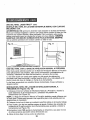
USING AS A HAND-HELD LEVEL (See Figures 12 and 13)
This level can be held in one hand for use as a straight line reference tool
(as shown in Fig. 12).
It can be easily adjusted with the finger or thumb 90 ° from a horizontal to
vertical line and all angles in between.
As a hand-held device the Laser Trac TM
Level can be used for quick reference
and alignment across any two points of
reference such as lining up cut-outs
and fixtures on drywall or checking wall
paper and paint trim. Also ideal for
insuring straight placement of mounted
fixtures and brackets, such as stair
railing fittings (as shown in Fig. 13).
Fig. 13
8
USING THE LASER TRAC
TM
LEVEL (cont.)
USING AS A WALL-MOUNTED
LEVEL (See Figures 14 to 17)
This level can also be wall-mounted using the special base included.
Figures 14 and 15 show the top and bottom views of the Thin-Pin Wall-Mount
Base° Figure 14 also shows the protective cover that snaps into the bottom of
the base when it is not in use.
There are two red buttons on the top of the base (see Fig° 14) that are used to
push the thin pins out of the base.
The thin pins (shown in Figure 15) can be driven into any softer wood or
wal!-board surface to secure the level,,
The thin pins in this base are designed to be easily removed from the
wood or wall-board surface.
This base also has an alignment pin for pivoting the tool on the base to aid in
referencing two points (see Fig. 14),_
Fig. 14
Alignment
Red Buttons
Pin
Fig. 15
Level
Thin Pins
Protective Cover
Alignment Pin
MOUNTING LEVEL TO THIN-PIN WALL MOUNT BASE
(See Figures 16 and 17)
1. Place level on the Thin-Pin Wall-Mount Base and slide either the front or back
of the tool into and around the alignment pin°
2. Switch the level "on'L DO NOT point the tool in the direction of your eyes or
anyone else's in the vicinity of use.
3. Place the level and wall-mount assembly on a soft wood or wallboard surface
(see Fig. 16).
4. Align the laser line with any two measured or leveled reference points or
level tool using built-in level vials for vertical or horizontal lines.
5. Push the thin pins into the surface using the red buttons on the base plate.
The Laser Trac TM Level can be used to align a single object or objects on one
surface as shown in Figure 16.
However its most effective use is for aligning multiple objects on multiple
surfaces such as the alignment of bath fixtures in a tub enclosure as shown in
Figure !7.
9
USINGTHE LASER TRACTM LEVEL (cont.)
MOUNTING LEVEL TO THIN-PIN WALL MOUNT BASE (cont.)
WARNING: DO NOT push the red buttons on the Thin-Pin Wall Mount
Base unless you plan to affix the base to a soft wood or wallboard surface.
This could result in injury, because the pins under the base are very sharp
instruments, ALWAYS HANDLE THIS BASE PLATE CAREFULLY. ALWAYS
use the protective cover on the base when not in use°
Fig. 17
Fig. '16__._.__i_I_
USING LEVEL WITH PRECISION MANUAL LEVELING BASE
This level can also be used with the Precision Manual Leveling Base for much
broader applications, such as framing and aligning windows, installing track
lighting, and lining up bath and kitchen cabinets.
The laser light can be used to pick up a single point of reference and project a
level horizontal or vertical line accurate to _+.
3/8-inch at 30 feet across the work
area in front of the toolo
The laser light will accurately
angies_
mark horizontal
lines, vertical lines and right
MOUNTING LEVEL TO PRECISION MANUAL LEVELING BASE
(See Figures 18 and 19)
1. Put the level on the Precision Manual Leveling Base and slide the front of
the tool into and around the alignment pin (see Figure 18)o
NOTE: The Precision Manual Leveling Base can also be used attached to the
Tripod Base to provide a more stable, flat surface for leveling operations_
2. Place the level with base on any flat surface in the work area.
3. Turn the three black adjustment knobs to level. There are two leveling vials on
top of the tool to help you level the tool (see Figure 19).
4. Switch the level "on". DO NOT point the tool in the direction of your eyes or
anyone else's in the vicinity of use,
5. Align the laser line with your point of reference.
10
USING THE LASER TRAC
TM
LEVEL (cont.)
Fig. 18
Fig, 19/_
ve.icaJ
Horizontat_
\
Adjustment
Knobs
Adjustment
Knobs
/
ent
Pin
I
USING LEVEL WITH TRIPOD
MOUNTING
BASE (see Figure 20)
This level can also be used with the Tripod Mounting Base that securely mounts
level to any tripod (not included)° This provides even more flexibility in the set
up and use of the laser level.
The use of a tripod with this tool is ideal for leveling kitchen cabinets,
countertops, window framing, plate rails and more,
MOUNTING LEVEL TO TRIPOD
MOUNTING BASE (see Figure 20)
1. Put the level on the Precision Manual
Leveling Base and slide the front of
the tool into and around the alignment
pin (see Figure 20).
2, Place the level and leveling base onto
the Tripod Mounting Base and turn the
three black adjustment knobs to mount
to tripod base (see Figure 20).
Fig. 20
_Level
Precision
Leveling
Base
I
I
3. Attach tripod base to tripod using the
standard t/4-20 UNC threaded fitting
included with tripod (see Figure 20).
4. Switch the level "on" DO NOT point
the tool in the direction of your eyes or
anyone else's in the vicinity of use_
5. Align the laser line with your point of
reference.
11
I
"_,
? ' -_
_ .....
I_. _
Tripod
Mounting
Base
I/4-20 UNC
Threaded
Standard
Fitting
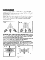
PROJECTING
LEVEL VERTICAL
LASER LINES (see Figures 2! and 22)
When used with the Precision Leveling Base the Laser Trac TM Level will project
a plumb vertical line on the surface directly in front of the tool from any angle in
the room (see Figure 21).
However, if you want to project a straight vertical line across two or more
adjacent surfaces (e.i., walls or ceilings), the Level and Precision Leveling Base
must be positioned directly in front of the work area to prevent the tool from
projecting an adjacent line that is at the same angle as the tool projection
angle (see Figure 22).
...............
,,i
Fig.
Fig. 21
i
7
|
PROJECTING LEVEL HORIZONTAL LASER LINES (see Figures 23 and 24)
When used with the Precision Leveling Base the Laser Trac TM Level will project
a level horizontal line on the surface directly in front of the tool for any height
the tool is set and horizontally leveled (see Figure 23).
tf you only want to project a level horizontal line on one surface, the toot can be
angled to line up with the mark or reference point (see Figure 23).
To project a straight horizontal line across two or more
adjacent surfaces, the Level and Precision Leveling Base must be precisely
leveled using both leveling vials on the tool. This will align the level to the same
height of the reference point which prevents the tool from projecting an adjacent
line that is at the same angle as the tool projection angle (see Figure 24).
Fig. 23
Fig. 24
12
This level has been designed to be a tow-maintenancetool However, in order
to maintain its performance, you must ALWAYS-follow these simple directions.
1. ALWAYShandle the tool with care°Treat it as you would any optical device,
such as a camera or binoculars_
2. AVOID exposingthe level to shock, continuousvibration or extreme hot or
cold temperatures.
3. ALWAYSstore the level indoors, When not in use, ALWAYSstore the level
in its protectivecase
4. When you are finished using the tool, ALWAYSmake sure that the switch
cover plate is in the full up and protected position°
5. ALWAYS keepthe level free of dust and liquids°Use a damp cloth' and mild
soap to clean the tool. If needed, ONLY USE a soft cloth or cotton swab and
glass cleaner to clean the lens
z_WARNING:
ALWAYS
remove the batteries when cleaning lens
6. ALWAYS clean and thoroughly
dry the tool after each use°
7. Check the batteries regularly to avoid deterioration
ALWAYS remove the
batteries from the tool, if it is not going to be used for an extended period
of time
8. Replace the batteries after approximately 40 hours of use
9. DO NOT disassemble the Laser Trac TM level. This will not only void the
warranty, but could expose the user to hazardous radiation exposure
10. DO NOT modify the tool in any way or use the tool with products and/or
accessories not specified by Sears, this could expose the user to hazardous
laser radiation exposure.
11. DO NOT attempt to change any part of the laser lens
12. Tool service MUST BE performed only by a Sears Parts and Repair Center.
Service or maintenance performed by unqualified personnel could result in
a risk of injury,,
13
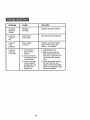
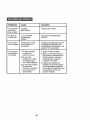
PROBLEM
CAUSE
SOLUTION
Laser line
projection
is weak_
Batteries
are weak_
Replace with fresh batteries
Laser line
is hard to
seer
Light in area
is too bright
Use laser enhancing glasses.
Laser line
is not
projected,
Power switch
is not "on".
Check to be sure the power
switch cover is in the full
down or "on" position.
Laser line
projected
is not level.
1. Thumb knob is
not in correct
position_
2, Level is mounted
on the thin-pin wall
mounting base,
3. Level is mounted
on the precision
leveling base, but
the base is no
longer level
1, Adjust thumb knob°
2. Align the tool using two
points of reference in the
work area or place the tool
on the precision leveling
base.
'14
3. Check the leveling vials on
the top of the tool, and
adjust the three base plate
knobs to bring the tool back
into a level position,,
NOTES
15
NOTES
16
iVlanual del Usuario
IVEL 4 en 1
con Laser Tr'aCM"
Modelo No.
320.48251
/_ ATENCION: Antes de usar
este producto, lea, comprenda
y siga todas las reqlas de
seguridad y las ms-trucciones
de funcionamiento incluidas en
este manual.
° SEGURIDAD
• FUNCIONAMIENTO
o rvlANTENIMIENTO
Sears, Roebuck and Co., Hoffman Estates, IL 60179 U.S.Ao
Garantfa ..........................................................
lnstrucciones de Seguridad ..........................
P&gina
PAgina
Descripci6n ......................................................
Funcionamiento ...........................................
Mantenimiento .................................................
P&gina 20
P&ginas 21 - 28
PAgina 29
Soluci6n de Aver[as .........................................
NQmeros de Servicio .......................................
PAgina
30
Contraportada
GARANTIA COMPLETA
LASER CRAFTSMAN
18
19
DE UN AI_O DEL NIVEL
Si este nivel I&ser CRAFTSMAN
no te otorga completa satisfacci6n
dentro de un a5o de ta fecha de compra, DEVUELVALO AL
ALMACEN SEARS MAS CERCANO
EN LOS ESTADOS UNIDOS
y Sears Io reemplazar#, gratuitamente.
Si este nivel l#,ser CRAFTSMAN
se usa para propSsitos comerciales
o de arriendo, esta garantfa es v&tida solamente durante 90 dfas
desde la fecha de compra.
Esta garantia le otorga derechos legales especfficos y usted
adem&s puede tener otros derechos que varfan de un estado
Sears,
Roebuck
and Co. DepL 817 WA, Hoffman
Estates, IL 60179
iCONSERVE ESTAS INSTRUCCIONES!
iLEA TODAS LAS INSTRUCCIONES!
18
a otro_
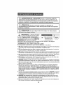
ADVERTENClA:
ASEGURESE
de leer y comprender
todas las
instrucciones
de seguridad indicadas en este manual,, El incumplimiento
de
todas las instrucciones
indicadas a continuaci6n
puede resultar en exposiciSn
peligrosa a radiaci6n, choque el6ctrico, incendio yio lesi6n personal.
ATENCiON:
Et uso de controles o ajustes o la ejecuci6n de
procedimientos
no especificados
en este manual puede resultar en exposici6n
pelJgrosa a radiaci6no
MlUlIH IIIII HIll U'l....
I
ATENCtON:
i aumentar&
los peligros
Et uso de algun instrumento
oculares.
6ptico con este producto
,........
ha
sido colocada Laenetiqueta
su niveLsiguiente
Indica
IMPORTANTE:
el lugar por donde el nivel emite ta
_.
Preducto L&serQ'eIa Ctase Ilia
"_,_:_
Emisbn de Radiaci6nL_ser
luz l&ser. SlEMPRE ESTE CONSClENTE
de
Potencia M_b_ima s 2.5 mW
su ubicaci6n cuando use el niveL SlEMPRE
Longilud deOnda- 650 nm
ASEGURESE
de informar a cualquier
espectador que se encuentre en la vecindad de uso, acerca de los peligros
inminentes a! mirar directamente
la luz i&ser,
Z_
iADVERTENClA!
Evite exposici6n
LUZ LASER, RADIAClON LASER
directa de los ojos, No mire fijamente
I
!
E,/ITE EKF'OSlCIOf_ J
el rayo l&ser.,
1. NO retire ni deteriore ninguna de las etiquetas del producto_ Si se retiran las etiquetas
dei producto se aumenta el riesgo de exposici6n a radiaci6n l&sero
2. NO mire directamente al rayo f&ser ni apunte el rayo laser directamente
otras persona&, Se puede causar una lesi6n ocular grave,
a los ojos de
3. NO coloque el nivel Laser Trac MRde manera que alguna persona pueda tener que mirar
intencional o accidentalmente el rayo l&ser. Se puede causar una lesiSn ocular grave,,
4. NO use ninguna herramienta 6ptica de aumento tal como, pero sin limitar, telescopios
ni teodolitos para ver el raye l&serr Se puede causar una lesi6n ocular grave,
5, NO trabaje con el nivel Laser Trac M_'cerca de los ni_os ni permita que los ni5os usen
la herramienta,, Se puede causar una lesi6n ocular grave,
6. SIEMPRE apague el nivel Laser Trac "" cuando no est_ en uso° Si deja la herramienta
encendida se aumenta el riesgo de que alguien inadvertidamente
mire en el rayo l,_sero
7o NO use el nivel Laser Trac "" en &reas combustibles, tales como en presencia de polvo,
gases o liquidos inflamables,
8. NO oprima los botones rojos de la Base de Montaje Mural con Clavijas Deigadas a
menos que usted vaya a instalar ta base en una superficie de madera blanda o en
tablas de fibra prensad& Esto podria causar una lesi6n pues las clavijas debajo de la
base son instrumentos muy afilados, SIEMPRE MANIPULE ESTA PLAOA DE BASE
CON MUCHO CUIDADO. SIEMPRE use la cubierta protectora en la base cuando no
est6 en uso,
9. Cuando use una de las placas de base con el nivel Laser Trac _R,SIEMPRE cerci6rese
de que la herramienta est_ firmemente instalada en la base. Se puede causar da_o a
la herramienta y/o una lesi6n grave para el usuario si la herramienta se cae,
10.SIEMPRE use solamente los accesorios recomendados por Sears para usar con el
nivel Laser Trac MR.El uso de accesorios que han sido dise_ados para usar con otras
herramientas I&ser puede causar una lesi6n grave,
'11.NO use el nivel Laser Trac MRpara ning0n otro propSsito que no sean los indicados en
este manual, Esto podria causar una lesi6n grave,
19
CONOZCA
SU NiVEL
(Ver Fig. 1)
Este nivel Laser Trac MRCraftsman
es una herramienta
Puede sostenerse
en la mano, montarse
horizontal o montar en un trJpode.
muy vers&til.
en la pared, colocarse
Proyecta una linea t&ser que recorre 90 ° completos
la vertical y todos los &ngulos intermedios.
desde
en una superficie
la posici6n
horizontal
a
El funcionamiento
se mejora aun m&s al usarlo en proyecci6n de frente ya que
coloca la linea I&ser en ambos lados de una obf_trucci6n o en superficies
mL_ltiples,.
Esta herramienta
de marcaci6n y nivetaci6n es f&cil de usar en muchas
aplicaciones,
ya sea en proyectos sencillos de decoraci6n del hogar hasta
instalaci6n profesional de armarios de cocina.
Este nivel Laser Trac MRCraftsman no est& calibrado como un dispositivo de
medici6n de altura y no debe usarse como tal, Proporcionar&
una marca de
referencia exacta cuando se usa como una herramienta
de mano o se instala en
la pared.
Cuando se usa con ta Base de Nivelaci6n a Precisi6n o con e! Soporte de
Tripode (ambos incluidos), proyectar& una linea horizontal o vertical nivelada
es exacta _+.
3/8 pulgada a 30 pies.
Nivel
Desplazamiento
o
_
___¢_...._L.._
_-_--J
Etiqueta
en Tripode
"OnlOff'
_
:
I _-""_/"/_
e _
/_------.-
Etiqueta
...................................
,u.......
ESPECIFICACIONES
,
,,tl
TECNICAS
Uso Recomendado
Tipo de Diodo Laser
t
En
el Interior
Diodo
Laser Rojo - 650 nm
Clase clel Laser
Clase Ilia, potencia
maxima <_2,5 mW
Suministro
2 pilas "AA" de 1,5-voltios
Etdctrico
_,
Precisi6n
, ,i,_ I,H
Vida Uti! Estimada de
la Pila
40 horas de uso continuo
con pilas alcalinas
Lfmite Optimo de
Temperatura de Operaci6n
30°F a 104 ° F (-1°0 a 40°0)
Exactitud
_+318pulg. a 30 pies
20
que
V_t_
_
u
INSTALACIONDE LAS PILAS (Ver
Figuras
2 y 3)
Este nivel Laser Trac MRusa dos pitas "AA".
IMPORTANTE:
ANTES de instalar las pilas, SlEMPRE compruebe
si el interruptor
'on/off' (encendido/apagado)
est#. en posiciSn hacia arriba (apagado) (ver Fig. 2)_
Fig. 2
_._
Fig. 3
T
1_ Gire la tapa negra de la _ila situada en la parte trasera
vuelta a la izquierda y retire la tapa (ver gig_ 3),
del nivel
2. Instate las pilas con la polaridad
de la pil&
en el compartimiento
indicada
en la etiqueta
3. Coloque nuevamente
la tapa negra en la herramienta
a la derecha para btoquearia.
PARA ENCENDER
LA HERRAMIENTA
El interruptor usado para encender
delantera de la herramienta.
(Ver Figura
y girela
1/4 de
1/4 de vuelta
4)
el nivel Laser Trac MRse encuentra
en la parte
1. Mueva la cubreplaca
del interruptor hacia abajo hasta ta posici6n m_.s inferior
z_ara
encender el lb.ser.
ADVERTENClA:
Cuando encienda el nivel Laser Trac MRSlEMPRE asegt]rese
de proteger sus ojos y los de las personas que est6n cerca suyo.
NUNCA
apunte el nivel Laser Trac uR a la cara de ninguna persona, ni a la suya.
2. Para apagar la herramienta,
mueva la
cubreplaca del interruptor
completamente
hacia arriba hasta que
se bloquee en la posici6n 'up'
(Off - Apagado)
Uso de los Lentes
.....
Fig. 4
Provistos
Con este nivel se incluye un par de lentes
protectores
est&ndares
de un material
El prop6sito
que est&n hechos
que intensifica
primordial
.......................................
la luz laser.
de estos lentes es mejorar
la visiSn de la l{nea laser de la
herramienta,
/_
ADVERTENClA:
Estos lentes NO proteger&n
resultar al mirar directamente
ta proyecci6n
21
los ojos contra da5o que podria
del I_tsero
AJUSTE DE LA PROYECCION
La linea I&ser proyectada
desde esta herramienta
puede ser ajustada 90 ° desde
ta posici6n vertical a la
horizontal yen todos los
&ngulos intermedios,
Use el bot6n corredizo negro
situado en la parte superior
de la herramienta para ajustar
el &ngulo.
1. Encienda la herramienta y
tenga cuidado de no
apuntarla a los ojos de
nlnguna persona°
2. Mueva el bot6n en cualquier
direcci6n para cambiar el
&ngulo de la linea I#.ser en
cualquier superficie
directamente en frente de
la herramienta,,
DE LA LINEA LASER (Ver Figura 5)
Fig. 5
USO DE LA BASE IVlAGNETICA (Ver Figuras 6 y 7)
El nivel Laser Trac M_tiene una base magnetlca (ver F1go6) que puede se
usada ya sea con la Base de Montaje Mural con Clavijas Delgadas o con la
Base de Nivelaci6n a Precisi6n (ver Fig° 7). La base magn6tica permite que la
herramienta pueda ser instatada en cualqu_er superficie plana de acero,
revestida o no revestida, de 13/4x 4 pulgadas. Esta caracteristica es
particularmente conveniente para trab_jar en estructuras de montantes de
acero y canalizaciones,
Para mayor informaci6n sobre el uso de esta
herramienta con las placas de base consulte la secci6n Uso del Nivel
Laser Trac MR en este manual.
Fig, 6
Magnetic Base
F'g' !
22
TRABAJANDO CON OBSTRUCCIONES
(Ver Figuras 8 y 9)
E INTERFERENCIA
DEL USUARIO
La Figura 8 ilustra la naturaleza de ta linea laser proyectada desde el nivel
Trac MR.Es en realidad un "plano" de luz laser. Esto es importante porque las
obstrucciones e interferencias del usuado que ocurran en frente del dispositivo
NO afectarAn la tinea laser proyectada en ambos lados del usuario o de la
obstrucci6no
La Figura 9 ilustra la habilidad del nivel Laser Trac Mnde proyectar una linea
derecha y nivelada en ambos tados de una obstrucciSn grande, tal como de un
calorifero de agua calienteo
Fig. 8
Fig. 9
REFERENCIACION
Y NIVELACION A TRAVES DE SUPERFICIES
ADYACENTES MULTIPLES (Ver Figuras 10 y 11)
El piano de luz del nivel Laser Trac MRes tambi_n Qtil cuando se trabaja con
dos o mAs superficies adyacentes.
La Figura t0 ilustra su uso al alinear cajas el_ctricas
paredes adyacentes.
en montantes
La Figura 11 ilustra algunos cuadros que estAn siendo alineados
_)aredes de una habitaci6n
Fig. 10
Fig. 11
J
23
con dos
en varias
USO DEL NIVEL LASER TRAC M"
Este nivel puede ser f&cil y convenientemente
usado de varias manera& Puede
ser usado en la mano, rnontado en la pared con la base provista de clavijas
delgadas o colocado en la base de nivelaci6n a precisi6n, Adem_ts use ta base
para tripode (incluida) para instalar el nivel en un tfipode (no incluido)o
USO COMO UN NIVEL DE IVlANO (Ver Figuras 12 y 13)
Este nivel puede ser sostenido en una mano para uso como una herramienta
de referencia de linea derecha (como se muestra en la Fig_ t 2).
Puede ser ajustado f&cilmente con el dedo o el pulgar 90 ° desde una linea
horizontal a una vertical yen todos los Angulos intermedio&
12
Como un dispositivo de mano, el nivel
Laser Trac MRpuede ser usado para
referencia y alineamiento r&pido a
trav6s de dos puntos de referencia, tal
como alineamiento de aberturas y
accesorios en drywall, verificaci6n de
bordes divisores en empapelados y
pintura de paredes. Tambi6n es ideal
para asegurar la colocaci6n derecha
de soportes y artefactos montados,
tales como accesorios de balaustradas
de escaleras (como se muestra en la
Fig. 13).
Fig. 13
24
USO DEL NIVEL LASERTRAC MRcont.
USO COMO UN NiVEL MURAL (Ver Figuras 14 a 17)
Este nivel tambi_n puede usarse montado en la pared usando la base especial
que se incluye. Las Figuras 14 y 15 muestran una vista superior e inferior de la
Base de Montaje Mural con Clavijas Delgadas. La Figura 14 tambi6n muestra
la cubierta protectora que se coloca a presiSn en la parte inferior de la base,
cuando no est_ en uso_
Hay dos botones rojos en la parte superior de la base (ver Fig. 14) que se usan
para empujar hacia fuera las clavijas delgadas de ta base.
Las clavijas delgadas (mostradas en la Figura 15) pueden ser clavadas en
cualquier superficie blanda de madera o fibra prensada para asegurar el niveL
Las clavijas detgadas de esta base han sido diseSadas para ser retiradas con
facilidad de la superficie de madera o de fibra prensad&
Esta base tambi_n tiene un pasador de alineamiento para pivotear la
herramienta en la base a fin de ayudar a referenciar dos puntos (ver Fig. 14)o
Fig. 14
Pasador de
Alineamiento
Fig. 15
Nivel
Botones Rojos
Cubierta Protectora
MONTAJE DEL NIVEL EN LA BASE DE MONTAJE MURAL CON CLAVIJAS
DELGADAS (Ver Figuras 16 y 17)
1. Coloque el nivel en la Base de Montaje Mural con Clavijas Delgadas y
deslice ya sea la parte delantera o trasera de la herramienta en y atrededor
de! pasador de alineamientoo
2. Encienda el nivelo NO apunte la herramienta en direcci6n a sus ojos ni a los
ojos de otras personas que est_n cerca del &rea de uso.
3. Coloque el conjunto del nivet y de la base en una superficie de madera
blanda o fibra prensada (ver Fig. 16).
4. Alinee la linea I&ser con cualquiera de dos puntos de referencia medidos o
nivelados, o nivele la herramienta usando las dos ampollas incorporadas
para lineas verticales u horizontaleso
5. Oprima los botones rojos de la placa de base para clavar las clavijas
detgadas en la superficie.
El nivel Laser Trac M_puede usarse para alinear un solo objeto o varios objetos
en una superficie, como se muestra en la Figura 16.
Sin embargo, su uso m_s eficaz es alinear objetos multiples en superficies
m_ltiples, tal como alineamiento de accesorios de baSo en el recinto de la
baSera, como se muestra en la Figura 17o
25
USO DEL NIVEL LASER TRAC MR cont.
MONTAJE DEL NIVEL EN LA BASE DE MONTAJE
DELGADAS cont.
MURAL CON CLAVlJAS
ADVERTENCIA'
NO oprima los botones rojos situados en la Base de Montaje
Mural con Clavijas Delgadas a menos que usted planee instalar la base en una
superficie de madera blanda o fibra prensada_ De io contrario, esto podria
causar una lesiSn pues las clavijas de la base son muy afiladas. SlEMPRE
MANIPULE CON MUCHO CUIDADO ESTA PLACA DE BASE. SIEMPRE
use ta cubierta protectora en la base cuando no est6 en usoo
Fig. 16 ___.
Fig. 17
j7
USO DEL NIVEL CON LA BASE DE NIVELACION
MANUAL A PRECISION
Este nivel puede adem&s usarse con la Base de Nivelaci6n Manual a Precisi6n
para aplicaciones m&s amplias, tales como enmarcaci6n y alineamiento de
ventanas, instalaci6n de deles de iluminaci6n y armarios de cocinaso
La tuz I&ser puede ser usada para captar un solo punto de referencia y
proyectar una ifnea horizontal o vertical exacta dentro de _+3/8 pulgada a 30
pies a trav6s del _rea de trabajo en frente de la herramienta,
La tuz I&ser proyectar_ con exactitud lineas horizontates, Ifneas verticales y
&ngulos rectos.
MONTAJE DEL NIVEL EN LA BASE DE NIVELACION MANUAL A
PRECISION (Ver Figuras 18 y 19)
1. Coloque el nivel en la Base de NivetaciSn Manual a Precisi6n e inserte la
parte delantera de la herramienta en y alrededor del pasador de
alineamiento (ver Figura 18)_
NOTA" La Base de Nivelaci6n Manual a Precisi6n tambi_n puede utilizarse con
la Base para Tdpode para proveer una superficie plana m&s estable para las
operaciones de nivelaciSn.
2. Cotoque el nivel con la base en cualquier superficie plana en et _rea de trabajo
3. Para nivelar, gire las tres peritlas negras de ajuste. Existen dos ampollas de
nivelaci6n en la parte superior de la herramienta para ayudarle a nivelar la
herramienta (ver Figura 19).
4. Encienda el niveL NO apunte ta herramienta en direcci6n a sus ojos ni a los
de otras personas que est6n cerca del &rea de uso.
5. Alinee la l_nea I&ser con su punto de referenciao
26
USO DEL NIVEL LASER TRAC MRcont.
Fig. 18
Perillasde
Ajuste
Perillasde
Ajuste
Nineamiento
USO DEL NIVEL CON LA BASE DE MONTAJE
EN TRIPODE
(ver Figura 20)
Este nivel tambi6n puede ser usado con la Base de Montaje en Tdpode que
permite la instalaci6n del nivet en un tripode (no inctuido), Esto proporciona a_n
m&s flexibitidad en el ajuste y uso del nivel l&ser.
E1 uso de un tripode con esta herramienta es ideal para la nivelaci6n de
armarios de cocina, meseras, marcos de ventanas, riefes de exhibici6n de
platos y m&s.
MONTAJE DEL NIVEL EN LA BASE
DE MONTAJE EN TRIPODE
(ver Figura 20)
1. Coloque el nivel en la Base de
Nivelaci6n Manual a Precisi6n e inserte
la parte delantera de la herramienta en
y alrededor del pasador de
alineamiento (ver Figura 20).
2. Coloque el nivel y la Base de
Nivetaci6n en la Base de Montaje en
Tripode y gire las tres peri!las negras
de ajuste para montarlo en la base de
tripode (ver Figura 20).
3. lnstale la base de tripode en el tripode
usando un accesorio roscado est&ndar
1/4-20 UNC incluido con el tripode
(ver Figura 20).
4. Encienda el nivel. NO apunte la
..............
herramienta en direcciSn a sus ojos ni a los de otras personas que est6n
cerca del b.rea de uso,
5. Atinee la linea I&ser con su punto de referencia.
27'
PROYECCION
DE LINEAS
LASER
DE NIVELVERTICALES
(ver Figuras
21 y 22)
Cuando se utiliza con la Base de Nivetaci6n a Precisi6n, el nivel Laser Trac MR
proyectar__ una I[nea de nivel vertical a plomo en ta superficie directamente
en
frente de la herramienta
desde cualquier Angulo de la habitaci6n (ver Figura 21).
Sin embargo, si usted desea proyectar una linea vertical derecha a trav6s de dos o
m&s superficies
adyacentes,
(por ej. paredes y cielo raso), el nivel y la Base de
NivelaciSn a PrecisiSn deben ser colocados directamente
en frente del &rea de
trabajo a fin de evitar que la herramienta
proyecte una linea adyacente que est6 en
el mismo &ngulo que el &ngulo de proyecci6n de la herramienta
(ver Figura 22).
Fig, 21
PROYECClON
DE LINEAS LASER DE NIVEL HORIZONTALES
(ver Figuras 23 y 24)
Cuando se utiliza con la Base de Nivelaci6n a Precisi6n, el nivel Laser Trac M_
proyectar& una linea de nivel horizontal en la superficie directamente
en frente de
la herramienta
para cualquier altura que se ajuste ia herramienta y horizontalmente
nivelada (ver Figura 23).
Si usted desea proyectar solamente una linea de nivel horizontal en una superficie,
la herramienta se puede oblicuar para alineada con la marca o punto de referencia
(ver Figura 23)°
Para proyectar una linea horizontal derecha a trav_s de dos o m&s superficies
adyacentes,
el nivel y la Base de NivelaciSn a Precisi6n deben estar exactamente
nivelados usando ambas ampollas de nivelaciSn de la herramienta.
Esto alinear&
el nivel a la misma attura del punto de referencia Io cual evita que la herramienta
proyecte una linea adyacente que est_ en el mismo &ngulo que el &ngulo de
proyecciSn de la herramienta
(ver Figura 24).
Fig. 24
==
"_: _ ii
!_;
:
_
::: i_i_::.:_ _
28
Este nivel ha sido disefiado como una herramientade bajo mantenimiento.
Sin embargo, para mantener su rendimiento,es necesarioque siga SIEMPRE
estas sencillas instrucciones.
I. SlEMPRE manipule con cuidado la herramienta.Tr&telaigual como trataria
cualquier otro dispositivo6ptico, tal como una cAmarafotogr&ficao gemelos
binocutares
2. EVITE la exposici6n del nivel a choques, vibraci6n continua o temperaturas
extremadamentecalientes o friaso
3. SIEMPREguarde el nivel al interior°Cuando no Io use, SIEMPREguarde el
nivel en su caja protector&
4. Cuandotermine de usar la herramienta, SIEMPRE asegLiresede que la
cubreplacadel interruptor est6 en la posici6n protegida- completamente
hacia arrib&
5. SlEMPRE mantenga el nivel libre de potvo y liquido& Use un patio hQmedo
y jab6n suave o un algod6n y limpiavidnospara limpiar el lente,
USE SOLAMENTE un patio suave o un algodSny limpiavidriospara iimpiar
el lente
Z_ADVERTENClA:
SlEMPRE
retire las pilas cuando limpie el lente,
6. SlEMPRIE limpie y seque bien la herramienta despu6s de cada usoo
7. Verifique regularmente las pilas para evitar su deterioro. SlEMPRE retire
las pilas de la herramienta si no va a ser usada pot un perfodo de tiempo
prolongadoo
8. Reemplace la pilas despu6s de aproximadamente
40 horas de uso_
9. NO desarme et nivel Laser Trac MR.Esto no s61o anula la garantia sino que
tambi6n expone al usuario a exposici6n peligrosa a radiaci6n.
10. I'40 modifique la herramienta de ninguna manera ni la use con productos
yio accesorios no especificados por Sears, Esto podria exponer al usuario
a exposici6n peligrosa a radiaci6n
11. NO trate de cambiar ninguna pieza del lente I&ser,
12. La reparaci6n de ta herramienta DEBE SER realizada solamente por un
Centro de Repuestos y Reparaci6n Sears. La reparaci6n o mantenimiento
realizado por personal no calificado puede ocasionar un riesgo de sufrir
una lesi6n
29
PROBLEIVlA
CAUSA
SOLUCION
La proyecci6n
de la I[nea
!_.seres d_biL
Las pilas
est&n d_biles
Cotoque pilas nuevas.
Es dificil ver
ta linea I_.sero
La luz ambiental
es dernasiado
brillanteo
Use lentes de intensificaci6n
del l&ser
La linea I&ser
no se proyecta,
El interruptor no est&
en la posici6n "on"
(encendido).
Verifique para asegurarse de que
la cubierta del interruptor est6
completamente hacia abajo, en la
posici6n "on" (encendido).
La linea I&ser
proyectada no
es nivelada.
1. El bot6n corredizo
no est#, en la
posici6n correcta
2. E! nivel est&
instalado en la base
de rnontaje mural
con clavijas delgadaso
3. El nivel est,. rnontado
en la base de
nivelaci6n a precisi6n,
pero ta base ya no
est& niveladao
1. Ajuste el bot6n corredizo,
2. Alinee la herramienta usando
dos puntos de referencia en el
&rea de trabajo o coloque la
herramienta en ta base de
nivelaci6n a precisi6n.
3. Verifique las ampollas de
nivelaci6n en la parte superior
de la herrarnienta y ajuste las
tres perillas de ta base para que
la herramienta vuelva a la
posici6n nivelada.
30
NOTAS
31
i ,:,,,,,,_:,,_,iii_"__"_,_"i!_,
_,
Get
ours!
it fixed, at yourhome,or
Your Home
For repair in your home of all major brand appliances,
lawn and garden equipment, or heating and cooling systems,
no matter who made it, no matter who sold it]
For the replacement parts, accessories and
owner's manuals that you need to dooit-yourselfo
For Sears professional installation of home appliances
and items like garage door openers and water heaters.
1-800-4-MY-HOME
(1-800-469-4663)
e
Anytime,
(US.A.
www.sears.corn
dayor
night
:,:
__i_i:_/
_i:,:i:::
'=_
,_?._.:_
_.
=:"::
and Canada)
www.sears.ca
Our Home
For repair of carry-in .products like vacuums, lawn equipment,
and electronics, call or go on-line for the nearest
Sears Parts and Repair Center,
1-800-488-1222
Anytime, day or night (UoSoA only)
www.sears.corn
,.
To purchase a protection agreement (U.S.A.) or maintenance
agreement (Canada) on a product serviced by Sears:
1-800-827-6655
?:i: ::i:;
(usA)
Para pedir servicio de reparaci6n
a domicilio, y para ordenar piezas:
1-888-SU-HOGAR sM
(1-8sB-784-6427)
1-800-361-6665
(Canada)
Au Canada pour service en fran_ais:
1-800-LE.FOYER Mc
(1-800-5,33-6937)
www sears,ca
© Seals, Roebuck and Co.,
® Registered
Trademark l'rM Trademark / sM Service Mark of Sears, Roebuck and Co.
_rw
/
Marca de F brica I SMMarc_ de Servicio de Sears, Roebuck and Co,
® Marca Registrada
MCMarque de commerce
1_
Marque d_posee
de Sears, Roebuck and Co
¸ii ii