1
LMU
Users Guide
Version 1.0.6
December 2009
V1.0.6
Copyright ©CalAmp DataCom Inc 2009
-1-
December 10 2009
CalAmp Proprietary & Confidential
LMU Users Guide
Table of Contents
Table of Contents ........................................................................................................................................ 1
1
Introduction ......................................................................................................................................... 5
1.1
About CalAmp – Who we are… ................................................................................................. 5
1.2
About CalAmp – What we do… ................................................................................................. 5
1.3
About this Manual ....................................................................................................................... 5
1.4
About the Reader ......................................................................................................................... 5
2
CalAmp LMU – Hardware Overview ............................................................................................... 6
3
LMU Setup – Configuration Overview ............................................................................................. 7
3.1
Parameters ................................................................................................................................... 7
3.1.1
What are Parameters? ....................................................................................................... 7
3.1.2
How does one program Parameters? ................................................................................ 7
3.2
S-Registers .................................................................................................................................. 9
3.2.1
What are S-Registers?........................................................................................................ 9
3.3
Parameter Masking .................................................................................................................... 10
3.3.1
What is Parameter Masking?........................................................................................... 10
3.3.2
What is a bit mapped parameter values? ......................................................................... 10
3.3.3
How is a mask used? ........................................................................................................ 10
4
Working with Inputs, Outputs and Power ..................................................................................... 11
4.1
I/O Introduction ......................................................................................................................... 11
4.2
Input Types ................................................................................................................................ 11
4.2.1
Digital Inputs ................................................................................................................... 11
4.2.2
Motion Sensor Input......................................................................................................... 13
4.2.3
Power State Input............................................................................................................. 13
4.2.4
Battery Voltage Critical Input.......................................................................................... 13
4.2.5
High Temperature Input .................................................................................................. 14
4.2.6
The 1 Bit Bus .................................................................................................................... 14
4.2.7
Analog to Digital Inputs................................................................................................... 15
4.3
Output Types ............................................................................................................................. 16
4.3.1
Relay Outputs................................................................................................................... 16
4.3.2
External vs. Internal Power Switch.................................................................................. 17
4.3.3
Enable / Disable Battery Charging .................................................................................. 17
4.3.4
LED Outputs .................................................................................................................... 17
4.4
Selecting the GPIO Function ..................................................................................................... 18
4.5
Working with Sleep Mode......................................................................................................... 19
4.5.1
Configuring the Input Wake-Up Monitor......................................................................... 19
4.5.2
Keeping the Expansion Port powered during sleep ......................................................... 20
4.5.3
Keeping the Modem On during sleep ............................................................................... 20
4.6
Working with the Status LEDs .................................................................................................. 21
4.6.1
Input State and Satellite Count Mode .............................................................................. 21
4.6.2
Alternate LED Blink Code ............................................................................................... 22
4.6.3
Disabling the Status LEDs ............................................................................................... 23
4.7
Restoring values through a power cycle .................................................................................... 24
5
Working with External Serial Devices ............................................................................................ 26
5.1
Using the Host Port ................................................................................................................... 27
5.1.1
Host Mode - AT Command Setup..................................................................................... 27
5.1.2
Host Mode – NMEA Output ............................................................................................. 28
5.1.3
Host Mode – Dial-Up Networking ................................................................................... 29
5.1.4
MDT Mode ....................................................................................................................... 31
5.2
Using the Aux Port .................................................................................................................... 36
5.2.1
NMEA Mode .................................................................................................................... 36
V1.0.6
Copyright ©CalAmp DataCom Inc 2009
-1-
December 10 2009
CalAmp Proprietary & Confidential
LMU Users Guide
6
7
8
9
5.2.2
MDT Mode ....................................................................................................................... 36
5.3
Using The Garmin NUVI or MacKenzie Labs DAD-A1214 .................................................... 40
5.4
Using the Modem Port .............................................................................................................. 41
5.4.1
Selecting a Modem Driver ............................................................................................... 41
5.4.2
Configuring the Modem Port’s BAUD Rate .................................................................... 42
5.4.3
Setting the dial string ....................................................................................................... 42
5.4.4
Setting the network username and password ................................................................... 43
Using the CalAmp Bluetooth Adapter (BTA)................................................................................. 44
6.1
Using the BTA as the Host Port ................................................................................................ 45
6.1.1
NMEA Output .................................................................................................................. 45
6.1.2
AT Command and Debug Output ..................................................................................... 45
6.1.3
Dial-Up Networking – Dial-Up Networking Profile ........................................................ 46
6.1.4
Dial-Up Networking – Serial Port Profile ....................................................................... 46
Working with Comm ........................................................................................................................ 47
7.1
Using a second Comm profile ................................................................................................... 47
7.2
GPRS context switching ............................................................................................................ 47
7.3
Automatically resetting the wireless modem ............................................................................. 48
7.3.1
Send fail restart ................................................................................................................ 48
7.3.2
Log activity restart ........................................................................................................... 49
7.3.3
Connection monitoring .................................................................................................... 49
7.3.4
Querying the modem for network status .......................................................................... 50
7.4
PDP Context Reset .................................................................................................................... 50
7.5
Network selection ...................................................................................................................... 50
7.5.1
GPRS networks ................................................................................................................ 52
7.5.2
CDMA networks ............................................................................................................... 52
7.5.3
iDEN networks ................................................................................................................. 52
7.6
Controlling the Data Session ..................................................................................................... 53
7.7
Updating the PRL ...................................................................................................................... 53
7.8
Back Off Algorithms ................................................................................................................. 54
7.9
Working with the Outbound Socket .......................................................................................... 54
Controlling LMU Access .................................................................................................................. 55
8.1
Service Enables ......................................................................................................................... 55
8.2
Access IP Address List .............................................................................................................. 56
8.3
Remote Host IP Address List .................................................................................................... 57
8.4
Primary Port Password .............................................................................................................. 58
8.5
AT Command Password ............................................................................................................ 58
Working with GPS ............................................................................................................................ 60
9.1
NMEA Messaging ..................................................................................................................... 60
9.2
GPS Timeouts ........................................................................................................................... 60
9.2.1
Last Known Timeout ........................................................................................................ 60
9.2.2
GPS Lost .......................................................................................................................... 60
9.2.3
GPS Restart ..................................................................................................................... 61
9.3
Pinning ...................................................................................................................................... 61
9.3.1
Enable / Disable pinning ................................................................................................. 61
9.3.2
Using Ignition to control Pinning .................................................................................... 61
9.3.3
GPS Accuracy Threshold ................................................................................................. 62
9.3.4
GPS Fix Quality ............................................................................................................... 62
9.3.5
The effects of Pinning....................................................................................................... 62
9.4
Special Functions ...................................................................................................................... 63
9.4.1
Receiver Mode ................................................................................................................. 63
9.4.2
Enabling SBAS Support ................................................................................................... 63
9.4.3
Elevation Filter ................................................................................................................ 63
9.4.4
Using Active or Passive GPS Antennas ........................................................................... 64
9.4.5
Update Rate ..................................................................................................................... 64
9.5
Local GPS Messaging ............................................................................................................... 65
V1.0.6
Copyright ©CalAmp DataCom Inc 2009
-2-
December 10 2009
CalAmp Proprietary & Confidential
LMU Users Guide
9.5.1
Odometer Message .......................................................................................................... 65
9.5.2
Position Update Message ................................................................................................ 66
9.5.3
GPS Debug Output .......................................................................................................... 68
9.6
Over-The Air Real-Time GPS Updates ..................................................................................... 68
10 CalAmp LMU Interface – LM Direct ............................................................................................. 69
10.1
Using the LM Direct Protocol ................................................................................................... 69
10.2
Inbound Settings ........................................................................................................................ 69
10.2.1
Message Logging ............................................................................................................. 70
10.2.2
Working with Retry Schedules – Inbound Retries ............................................................ 71
10.2.3
Working with Retry Schedules – Log Retries ................................................................... 71
10.2.4
Using Multiple Inbound Addresses .................................................................................. 72
10.3
Maintenance Settings ................................................................................................................ 75
10.3.1
Maintenance Delivery ...................................................................................................... 75
10.3.2
Maintenance Configuration ............................................................................................. 75
10.3.3
Maintenance Interval ....................................................................................................... 75
10.4
Null Messaging.......................................................................................................................... 75
10.5
Changing the Local Port ............................................................................................................ 76
11 CalAmp LMU Interface – SMS ....................................................................................................... 77
11.1
Reporting Data via SMS............................................................................................................ 77
11.1.1
SMS Event Report ............................................................................................................ 78
11.1.2
SMS Text Status Message................................................................................................. 81
11.1.3
SMS Text Message ........................................................................................................... 84
11.1.4
SMS GPS Status Message ................................................................................................ 85
11.1.5
SMS Comm Status Message ............................................................................................. 86
11.2
SMS Request Messages............................................................................................................. 88
11.2.1
Unit Request Messages .................................................................................................... 88
11.2.2
SMS Parameter Message ................................................................................................. 89
11.2.3
Serial Message Request ................................................................................................... 90
12 CalAmp LMU Interface – TAIP ...................................................................................................... 91
12.1
TAIP Sentences ......................................................................................................................... 91
12.1.1
General Sentence Structure ............................................................................................. 91
12.1.2
PV (Position Velocity) Sentence Structure ....................................................................... 92
12.1.3
LN (Long Navigation) Sentence Structure ....................................................................... 92
12.1.4
IO (Input / Output) Sentence Structure ............................................................................ 93
12.1.5
Optional Fields ................................................................................................................ 93
12.2
TAIP Settings ............................................................................................................................ 96
12.2.1
Enabling TAIP ................................................................................................................. 96
12.2.2
Message Selection ............................................................................................................ 96
12.2.3
Message Destination ........................................................................................................ 97
12.2.4
Local Port ........................................................................................................................ 97
12.3
TAIP Reporting ......................................................................................................................... 97
12.3.1
Scheduled Reporting – Standard Mode ........................................................................... 98
12.3.2
Scheduled Reporting – Directed ...................................................................................... 98
12.3.3
PEG Reporting ................................................................................................................. 98
12.3.4
SMS Reporting ................................................................................................................. 98
13 LMU Maintenance ...........................................................................................................................100
13.1
Mobile ID .................................................................................................................................100
13.2
Firmware Versioning ................................................................................................................101
13.3
Configuration Versioning .........................................................................................................101
13.4
Downloading Firmware ............................................................................................................102
13.5
Downloading Firmware – Locally ............................................................................................102
13.5.1
Local Firmware Upgrade ...............................................................................................102
13.5.2
Local Firmware Upgrade – LMU-1000™ ......................................................................103
13.6
Downloading Firmware – Remotely ........................................................................................104
13.6.1
Remote Firmware Upgrade – LMU 1000™ ...................................................................104
V1.0.6
Copyright ©CalAmp DataCom Inc 2009
-3-
December 10 2009
CalAmp Proprietary & Confidential
LMU Users Guide
14
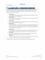
LMU Programming Examples ........................................................................................................105
14.1
LMU Programming – Delivery Fleet .......................................................................................106
14.1.1
Project Overview ............................................................................................................106
14.1.2
Project Proposal .............................................................................................................106
14.1.3
LMU Setup – Planning....................................................................................................107
14.1.4
LMU Setup – Development .............................................................................................108
14.2
PEG Programming – Long Haul Trucks ..................................................................................112
14.2.1
Project Overview ............................................................................................................112
14.2.2
Project Proposal .............................................................................................................112
14.2.3
LMU Setup – Planning....................................................................................................113
14.2.4
LMU Setup – Development – LMU 4100™ ....................................................................114
14.2.5
LMU Setup Development – LMU-1000™.......................................................................115
14.3
LMU Programming – Taxi System ..........................................................................................116
14.3.1
Project Overview ............................................................................................................116
14.3.2
Project Proposal .............................................................................................................116
14.3.3
LMU Programming – Planning ......................................................................................117
14.3.4
LMU Setup – Development .............................................................................................118
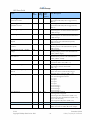
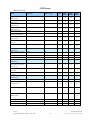
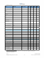
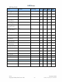
Appendix A — Parameter Definitions .....................................................................................................122
Appendix B — S-Register Settings...........................................................................................................135
Appendix C — ASCII Chart ....................................................................................................................161
Hexadecimal to ASCII ............................................................................................................................161
Decimal to ASCII ...................................................................................................................................161
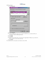
Appendix D – HyperTerminal Setup .......................................................................................................162
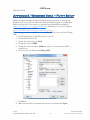
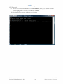
Appendix E - Windows Vista – Putty Setup ............................................................................................165
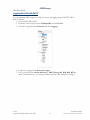
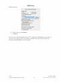
Logging data to file with PuTTY ............................................................................................................167
Appendix F - Pairing to the LMU-4100 Using Windows Mobile ..........................................................169
Appendix G - Adding a Modem Driver ...................................................................................................170
Windows Vista .......................................................................................................................................170
Windows XP ...........................................................................................................................................177
Windows Mobile 5.0 ..............................................................................................................................183
Appendix H – Creating a Dial-Up Networking Session .........................................................................184
Windows Vista .......................................................................................................................................184
Windows XP ...........................................................................................................................................192
Windows Mobile ....................................................................................................................................200
V1.0.6
Copyright ©CalAmp DataCom Inc 2009
-4-
December 10 2009
CalAmp Proprietary & Confidential
LMU Users Guide
1 Introduction
1.1
About CalAmp – Who we are…
Founded in 1981, CalAmp stands at the forefront of technology evolution as a result of
strategic collaborations with forward thinking customers. By anticipating technology and
industry trends, we rapidly develop cutting-edge solutions to help our customers effectively
realize time and cost savings. Based on our long history of successful product deployment
we help our customers by managing the entire product lifecycle - from design to
manufacturing to implementation.
1.2 About CalAmp – What we do…
We are a recognized and trusted leader in satellite DBS technology, wireless networks,
software application development, embedded computing and enterprise mobility. We are
considered the solution industry’s foremost specialist in networking applications, wireless
technologies, digital multimedia delivery, residential broadband data delivery, healthcare and
medical and public safety.
1.3 About this Manual
This guide is meant to be a comprehensive description of all features of the CalAmp LMU
product lines and their associated peripherals. The only exceptions are features having to do
with PEG or LM Direct. These features are described in the PEG™ Programming Guide
and LM Direct Reference Guide. All hardware, activation and installation information can be
found in the corresponding Installation Guides.
When a feature is common to all products the device will be referenced as the CalAmp
LMU, or just LMU. When a feature is device specific, the full version of the device (LMU4100™, LMU-2500™, LMU-1200™, etc…) will be used.
1.4 About the Reader
This document is intended for any personnel who are required to activate, configure and
install an LMU. It is expected that the reader has some familiarity with vehicle hardware as
well as basic knowledge of the Windows ™ operating systems. Specific knowledge of
HyperTerminal and Windows Dial-Up Network is required.
V1.0.6
Copyright ©CalAmp DataCom Inc 2009
-5-
December 10 2009
CalAmp Proprietary & Confidential
LMU Users Guide
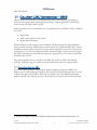
2 CalAmp LMU – Hardware Overview
In today's competitive market place, many companies rely on telemetrics in their business to
remove or minimize the risks associated with vehicle investment, improving efficiency,
productivity and reducing their overall transportation costs. CalAmp products offer easy
solutions to a wide range of markets.
•
•
•
•
•
•
•
•
LMU-4100™
Cutting-edge location technology in an affordable device with the intelligence to help
meet customer's ever changing needs
LMU-2500™
This ultra-sensitive tracking device is unrivaled in its class with next generation GPS
technology at an economical price.
LMU-1200™
This economical, full-featured device was designed for easy and reliable installation
and features an internal back-up battery
LMU-1100™
The LMU-1100™ is an economical, fully sealed vehicle tracking product designed
for easy and reliable installation in recreational vehicles. The LMU-1100™ is an ideal
solution for asset monitoring and theft recovery for motorcycles, snowmobiles and
other outdoor recreational vehicles.
LMU-1000™
This economy class device provides economical asset management. The unit can be
fully customized to meet the specific requirements of any particular application.
LMU-900™
This device is an ideal solution for automotive insurance, stolen vehicle, vehicle
finance, auto rental and other automotive tracking applications.
MTU-100
This fully sealed mobile tracker is ideal for monitoring person assets such as patients,
work force, VIPS and pets or mobile equipment and containers
Full details for each product can be found in their corresponding installation guide.
V1.0.6
Copyright ©CalAmp DataCom Inc 2009
-6-
December 10 2009
CalAmp Proprietary & Confidential
LMU Users Guide
3 LMU Setup – Configuration Overview
This section describes how the LMUs store their configuration data and how they are
programmed. The meaning of each parameter will be touched upon in the sections that
follow. A complete listing of parameters and S-registers can be found in Appendix A and B
respectively.
3.1 Parameters
3.1.1 What are Parameters?
Parameters are how the LMU stores any of its configuration items thus; any setting that can
be changed is contained within a Parameter.
Parameters are made up of three values, an ID, an Index and a Value.
The Parameter ID describes what the Parameter is, how many Indexes are available and
what data the Value should contain. As an example, the Inbound Address contains 4 Indexes
and stores an IP address. Parameter ID values may range from 0 to 65535, though only
certain values have any meaning.
In many cases there are multiple Values associated with a given Parameter ID, for example
there are 16 possible PEG Timers. The Parameter Index indicates which of the Values you
are attempting to access. Indexes start from 0 and range to N-1 where N is the total number
of available Values. For example, the 16 PEG Timers would range from Index 0 (the 1st
timer) to Index 15 (the 16th Timer). Indexes can range from 0-255 (technically). It is very
important to make sure you do not exceed the maximum index value for a given Parameter
as this may cause unexpected behaviors in the LMU.
The last piece of a Parameter is the Value. The Value contains the actual setting of the
Parameter such as 15s for a Timer. Some Parameters support Values with multiple parts.
The PEG Zone Parameter is a good example of this. The Value of a PEG zone is split into
6 parts, a latitude, a longitude, 2 distance values, a spare value and a hysteresis value. The
contents of the Value of a Parameter are defined by the Parameter ID.
Please refer to Appendix A for a complete listing of Parameter IDs, their Index ranges and
the Value definitions.
There is, however, one configuration item that is not stored in a Parameter, namely GeoZones (i.e. the points and polygon zones). They have their own separate programming
interfaces which are discussed in the PEG Programmers Guide and the LM Direct
Reference Guide.
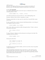
3.1.2 How does one program Parameters?
Parameters are programmed in one of three ways, either via AT Commands using the
AT$APP PARAM, via an LM Direct™ Parameter Message or via an SMS Parameter
Message. This manual will always use the AT Command based means of programming
V1.0.6
Copyright ©CalAmp DataCom Inc 2009
-7-
December 10 2009
CalAmp Proprietary & Confidential
LMU Users Guide
Parameters. The LM Direct™ Parameter Message is described in the LM Direct™
Reference Guide. The SMS Parameter Message is described later in this document.
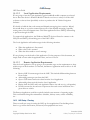
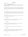
3.1.2.1 AT Commands
The AT$APP PARAM commands can be used to query or set Parameter Values. The set
command generally looks like:
AT$APP PARAM <ID>, <index>, <value>
It should be noted that there can be more than one <value> field depending on the
Parameter’s definition. Each sub-Value is separated by a comma.
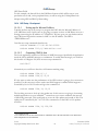
The query command takes two forms, query for a single Value of a specific Index or query
for all Values.
To query a specific Value, you need to reference which Parameter Index you are looking for.
The command would look as follows:
AT$APP PARAM? <ID>,<index>
If the <index> field is not provided, the LMU will responds with the 1st index (i.e. index 0).
The response will look like:
<ID>,<index>,<value>
OK
To query all Values of a Parameter a wild card character is used in place of the Index. This
command would look as follows:
AT$APP PARAM? <ID>,*
The response will look like:
<ID>,<index 0>,<value 0>
<ID>,<index 1>,<value 1>
. . .
<ID>,<index N>,<value N>
OK
For Parameters with a large number of Indices, such as the event list, it may not be possible
to display all Parameters.
Like the programming command there may be more than one <value> field for a given
parameter. Each value is separated by a comma. The one exception is masks. Mask values
are not displayed in the query response but they are required in the programming command.
Masks are discussed later in this document.
V1.0.6
Copyright ©CalAmp DataCom Inc 2009
-8-
December 10 2009
CalAmp Proprietary & Confidential
LMU Users Guide
The LMU does support several other AT Commands beyond the Parameter commands. The
most common ones are mentioned through-out this document.
A terminal program such as HyperTerminal is generally used to issue AT Commands to the
LMU. Please refer to Appendix D for instructions on establishing a connection.
3.1.2.2 Parameter Messages
Parameter Messages are a means of remotely changing the parameter values of an LMU
remotely. They can be sent in one of two ways, either via SMS or via an LM Direct™
Parameter message.
SMS Parameter Messages are discussed in detail later in this document. LM Direct™
Parameter Messages are discussed in the LM Direct Reference Guide.
3.2 S-Registers
3.2.1 What are S-Registers?
S-Registers are a standard means of configuring and programming Hayes compatible
modems. Any modem, or modem like device typically supports some range of S-Registers.
The LMU does not support any of the more standard lower S-Registers (such as S-Register
0, which is typically used as the number of rings to wait before answering an incoming call).
The LMU’s S-Registers begin at S120.
S-Registers are accessed through Parameter ID 1024. S-Registers, however, differ from other
Parameters in two ways: first, their Values tend not to change once the LMU is fully
configured. For instance, S-Register 120 is used to select what type of wireless modem the
LMU is using. The other difference is they have an alternate AT Command that can be used
to set and query their values. The commands are:
Set:
Query:
ATS<n>=<value>
ATS<n>?
Query Response:
<value>
OK
S-Registers programmed via this command cannot be masked. To do masking, the
Parameter command described above must be used. Masking is described below.
There are currently 51 S-Registers and can range in value from 0 – 255. The available SRegisters and their settings are listed in Appendix B.
V1.0.6
Copyright ©CalAmp DataCom Inc 2009
-9-
December 10 2009
CalAmp Proprietary & Confidential
LMU Users Guide
S-Registers start at S-120 and end at S-171. For the Parameter commands (or messages) this
corresponds to an Index range of 0 to 51. That is, the Index of an S-Register is the SRegister number minus 120.
3.3 Parameter Masking
3.3.1 What is Parameter Masking?
Parameter masking is a means of programming select parts of a Parameter’s Value. This only
applies to Parameter Values that are bit mapped. It is important to note that ALL S-registers
must be masked when they are programmed via the Parameter AT Command. When using
the ATS<n> command a mask value of 255 (0xFF) is automatically used. PULS™ also
assumes a full mask for any bit mapped value it changes.
3.3.2 What is a bit mapped parameter values?
Bit mapped Parameter Values are ones where each bit controls a different setting within the
LMU. That is, each bit tends to turn on or off a particular feature (say the TAIP interface)
depending if the bit is set or cleared. Bit mapping of values is most common in S-Registers,
though there are some other Parameters that support it.
3.3.3 How is a mask used?
A Mask allows a programmer to select which bits of a Value to change. That is, if bit 0 in the
mask is set, then the value of bit 0 can be changed. The mask value has the same range as the
Value. That is a 1 byte Value (range of 0-255) will have a 1 byte mask (also ranging from 0255).
V1.0.6
Copyright ©CalAmp DataCom Inc 2009
- 10 -
December 10 2009
CalAmp Proprietary & Confidential
LMU Users Guide
4 Working with Inputs, Outputs and
Power
4.1 I/O Introduction
The CalAmp LMU products offer a variety of inputs and outputs to enable a wide variety of
vehicle and asset tracking applications. For a complete description of what types of inputs
and outputs are supported by a given device, please refer to its installation guide.
4.2 Input Types
The LMU products offer the following input types. Please note that not all inputs are
supported by all products.
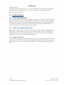
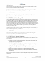
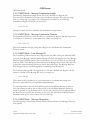
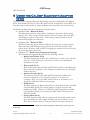
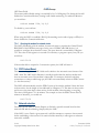
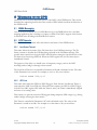
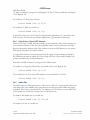
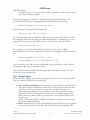
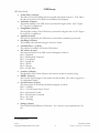
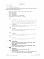
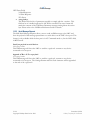
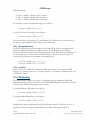
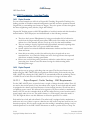
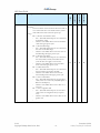
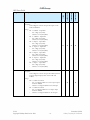
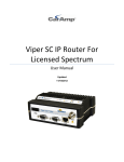
4.2.1 Digital Inputs
Digital inputs are meant to detect on/off behaviors such as ignition on/off or door
opened/closed.
The LMU’s digital inputs are protected from typical vehicle transients and can be directly
connected to most vehicle level logical inputs from 6 volts up to vehicle power. Their input
impedance is approximately 10 kΩ.
The Ignition input is pulled to ground through a 10kΩ resistance, where the other inputs can
be configured to be biased high or low. For those biased high, the input is pulled to the
supply voltage through a 10 kΩ resistor. For those biased low, they are pulled to ground
through a 10 kΩ resistor. The diagrams below show some typical connections to the inputs
in both a high- and low-biased configuration:
V1.0.6
Copyright ©CalAmp DataCom Inc 2009
- 11 -
December 10 2009
CalAmp Proprietary & Confidential
LMU Users Guide
Figure 1 - Sample Digital Input Wiring
V1.0.6
Copyright ©CalAmp DataCom Inc 2009
- 12 -
December 10 2009
CalAmp Proprietary & Confidential
LMU Users Guide
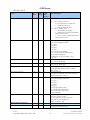
4.2.1.1 Changing the Input Bias
For some LMU products, the input Bias can be controlled by S-Register 158 (or Parameter
1024, Index 38). Each bit of this register is assigned to a specific input. If the associated bit is
set, then the input is biased high, if the bit is cleared, then the input is biased low. The input
to bit mapping is as follows:
Bit
0
1
2
3
4
5
6
7
Input
Not Used
Input 1
Input 2
Input 3
Input 4
Input 5
Input 6
Input 7
S-Register Mask
2
4
8
16
32
64
128
For example, to bias inputs 1, 3, 5 and 7 high and bias 2, 4 and 6 low, you would use the
following 7 commands:
AT$APP
AT$APP
AT$APP
AT$APP
AT$APP
AT$APP
AT$APP
PARAM
PARAM
PARAM
PARAM
PARAM
PARAM
PARAM
1024,38,2,2
1024,38,4,0
1024,38,8,8
1024,38,16,0
1024,38,32,32
1024,38,64,0
1024,38,128,128
Alternatively you could have used a single command of:
ATS158=170
(i.e. 128+32+8+2)
4.2.2 Motion Sensor Input
Some of the LMU products support an internal motion sensor as one of the discreet inputs.
In this case, the LMU detects motion when the input is in the High state. If the LMU does
not detect motion, then the input will be in the Low state. The sensitivity of the motion
sensor input is controlled by S-Registers 175 and 176.
4.2.3 Power State Input
Some of the LMU products can detect if they are using external power or if they are using
their internal back-up battery. If they are using external power, this input will be in the Low
state. If they have switched to the internal battery, then the input will register in the High
state.
4.2.4 Battery Voltage Critical Input
The LMU-1100 and LMU-1200 have a built in low battery threshold of 3500mV, which is
tied to a discreet input. If the battery level is above the threshold, then the input is in the
Low state. If the battery level is below the threshold, the input will be in the High state.
V1.0.6
Copyright ©CalAmp DataCom Inc 2009
- 13 -
December 10 2009
CalAmp Proprietary & Confidential
LMU Users Guide
4.2.5 High Temperature Input
The LMU-1100 and LMU-1200 have a built in high temperature threshold of 60 °C. If the
internal temperature of the LMU is above this value, then the input will be in the High state.
If the LMU’s temperature is below this value, then the input will be in the Low state.
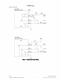
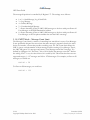
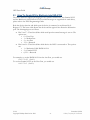
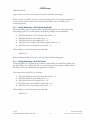
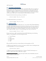
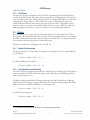
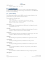
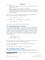
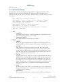
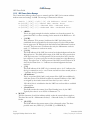
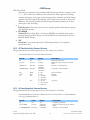
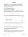
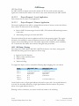
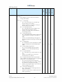
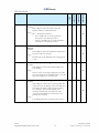
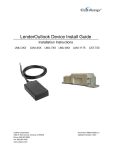
4.2.6 The 1 Bit Bus
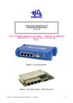
The 1-Bit-Bus allows the LMU-4100™ and LMU-2500™ to be connected to a variety of 1Wire® Devices. The LMU-4100™ supports the iButton Driver ID products and the LMU2500 supports the iButton Driver ID and Temperature Sensor products.
To connect an iButton DS9202 Probe to the LMU you would connect the Black wire to
Ground (Pin 16 on the LMU-2500™and Pin 5 on the LMU-4100) and connect the Grey
wire to the 1-Bit Bus input (Pin 17 on the LMU-2500™ and Pin 7 on the LMU-4100™) as
shown below.
Figure 2 - Sample 1 Bit Bus Wiring
On the LMU-4100™, the 1-Bit Bus interface must be enabled by setting Bit 0 of S-Register
171.
Enable 1-Bit Bus Input/ Disable Output 0:
AT$APP PARAM 1024,51,1,1
Disable 1-Bit Bus Input / Enable Output 0
AT$APP PARAM 1024,51,1,0
On the LMU-2500™, you must select which device the LMU is using (i.e. iButton Driver ID
tag or Temperature Sensor) on the 1-Bit Bus interface using Bit 6 of S-Register 171. The
temperature sensor is enabled when Bit 6 is set and the ID tag is enabled when Bit 6 is
cleared.
V1.0.6
Copyright ©CalAmp DataCom Inc 2009
- 14 -
December 10 2009
CalAmp Proprietary & Confidential
LMU Users Guide
Enable Temperature Sensors:
AT$APP PARAM 1024,51,64,64
Enable ID Tag
AT$APP PARAM 1024,51,64,0
The LMU-2500™ can work with up to eight (reference 0-7) Maxim DS28EA00 1-wire
temperature sensors in a chain configuration interconnected by a 3-wire bus. Upon boot-up,
the LMU executes a discovery procedure to detect the number of connected DS28EA00
devices. The LMU assigns each sensor a reference number starting with zero (0) for the
sensor closest to the LMU in the sensor chain and incrementing for each sensor down the
chain up to seven (7). During operation, the LMU sequentially polls each sensor for its
temperature reading; one sensor every 10 seconds. If all eight sensors are deployed, each
sensor will be polled every 80 seconds. A poll involves commanding the sensor to perform
the temperature conversion and 1-sec later reading the results of the conversion
4.2.7 Analog to Digital Inputs
The LMU’s Analog to Digital (ADC) Inputs are used to convert an analog signal into a
discrete voltage value. The meaning of the discrete voltage value will depend on the type of
device being used.
All of the LMU’s Analog to Digital inputs store values with a 1mV lsb. For example, if the
Analog to Digital Input reads a 12000, it means the input signal was measured as 12V.
4.2.7.1 Voltage Monitors
The Voltage Monitor ADCs are generally used to keep track of the LMU’s supply voltage.
The ADCs are read with a 1mV lsb. For example, a typical vehicle power supply reads as
13.8V while in operation. The corresponding voltage monitor ADC (typically ADC 0) would
read as 13800mV.
4.2.7.2 GPS Antenna
The GPS Antenna ADC on the LMU-2500 measures the voltage at the GPS Antenna to
determine if a short or open circuit condition is present. The voltage reported is in mV and,
in normal situations, should be approximate 3000mV (i.e. 3VDC).
V1.0.6
Copyright ©CalAmp DataCom Inc 2009
- 15 -
December 10 2009
CalAmp Proprietary & Confidential
LMU Users Guide
4.3 Output Types
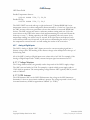
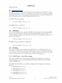
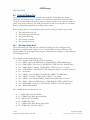
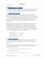
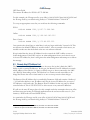
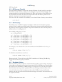
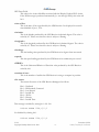
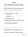
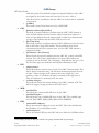
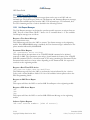
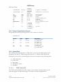
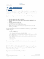
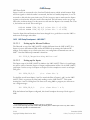
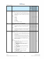
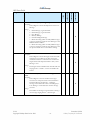
4.3.1 Relay Outputs
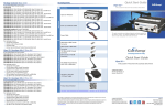
The LMU’s outputs are designed to drive external relays. These outputs provide a highcurrent, open-collector driver that can sink up to 150 mA each. These drivers may be used to
drive external relays that can then control vehicle functions such as door locks, fuel shut-off
valves, sirens and lights. If additional current is required to drive the relays, external circuitry
can be added to source the current. This diagram shows a typical relay connection to one of
the LMU’s outputs.
Vehicle Power
(+12VDC)
Relay
86
87
Relay
Contacts
Relay
Coil
LMU
30
Output 0
85
Ground
Figure 3 - Sample Relay Output Wiring
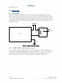
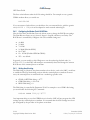
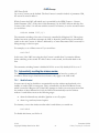
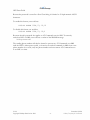
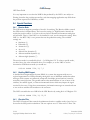
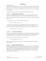
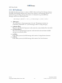
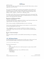
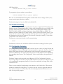
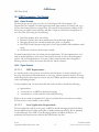
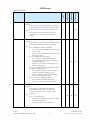
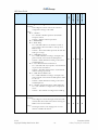
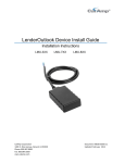
4.3.1.1 LMU-1000™ vehicle disable feature
To use the LMU-1000™’s vehicle disable feature, the ignition wire on the vehicle going
between the starter relay and the ignition key switch should be cut. The two cut ends should
be connected to the LMU-1000™ Relay Contact wires (blue/pin 2 and green pin 3). It
doesn’t matter which of the two cuts ends connects to which Relay Contact wire.
V1.0.6
Copyright ©CalAmp DataCom Inc 2009
- 16 -
December 10 2009
CalAmp Proprietary & Confidential
LMU Users Guide
Key Switch
Cut wire
BLUE
GREEN
LMU-1000
Starter Relay
Figure 4 - LMU-1000™ Vehicle Disable Feature
Using the above set-up a vehicle can be enabled or disabled by clearing (enabled) or setting
(disabled) output 0 via PEG Scripts, Real-Time PEG Actions or SMS messages.
4.3.2 External vs. Internal Power Switch
This output allows the LMU to switch between power sources when certain conditions are
met (e.g. low power on the currently selected supply). If this output is set then the LMU will
use its internal battery as its power supply. If this output is cleared, the LMU will use the
external power supply.
By default, this output is cleared so the LMU will operate off external power.
4.3.3 Enable / Disable Battery Charging
This output allows the LMU to enable or disable the charging of its internal battery. If this
output is set then the LMU will stop charging the internal battery. If this output is cleared
the LMU will charge the internal battery.
By default, this output is cleared (i.e. battery charging enabled)
4.3.4 LED Outputs
On the LMU-1000™ the LED outputs mirror the behavior of the Comm and GPS Status
LEDs. These allow an installer to remote the LEDs from the LMU-1000™ so they can be
observed to verify an install.
V1.0.6
Copyright ©CalAmp DataCom Inc 2009
- 17 -
December 10 2009
CalAmp Proprietary & Confidential
LMU Users Guide
4.4 Selecting the GPIO Function
The input or output functionality of the GPIO pins is controlled by S-Register 159. Like the
input bias controls, each bit is associated with a different GPIO. If the bit is set, then the
GPIO will act as an output. If the bit is cleared, the GPIO will act as an input. The following
bit mappings are available:
Bit
0
1
Input
GPIO 1
GPIO 2
S-Register Mask
1
2
For example to set GPIO 1 as an output and GPIO 2 as an input you would use:
AT$APP PARAM 1024,39,1,1
AT$APP PARAM 1024,39,2,0
Or you could use the single command of
ATS157 = 1
V1.0.6
Copyright ©CalAmp DataCom Inc 2009
- 18 -
December 10 2009
CalAmp Proprietary & Confidential
LMU Users Guide
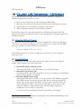
4.5
Working with Sleep Mode
4.5.1 Configuring the Input Wake-Up Monitor
The LMU’s digital inputs have an additional feature besides simple On/Off detection which
is to wake the LMU out of its sleep mode. The LMU is capable of filtering which input(s)
can wake it from sleep based on Parameter 1029. Like S-Registers 157 and 158, each bit of
Parameter 1029 is associated with a specific input. If the bit associated with that input is set,
then the LMU will wake up on any high to low or low to high transition of that input. If the
bit is cleared, the LMU will ignore any transitions for that input while it is sleeping.
A host device can also be used to wake the LMU from sleep via a wired serial connection
using the Serial Cable, ioPOD or TetheredLocator adapters. The LMU must also be set
NOT to power down its expansion port while sleeping. The LMU cannot be woken using
the Bluetooth Adapter, nor can it be woken remotely.
The bit mappings for the Wake-Up Monitor are as follows:
Input
Ignition/Input 0
Input 1
Input 2
Input 3
Input 4
Input 5
Input 6
Input 7
Bit
0
1
2
3
4
5
6
7
S-Register Mask
2
4
8
16
32
64
128
How the LMU enters sleep and how to monitor for wake up events is discussed in the PEG
Programming Guide. Please refer to that document for details.
V1.0.6
Copyright ©CalAmp DataCom Inc 2009
- 19 -
December 10 2009
CalAmp Proprietary & Confidential
LMU Users Guide
4.5.2 Keeping the Expansion Port powered during sleep
The expansion port is the 16 pin connection on the back of the LMU where peripheral
devices are plugged in. This port can actually remain powered while the LMU is sleeping.
This would be done to allow any of the following:
•
•
•
Keep Inputs and Outputs on the ioPOD in the High/Low or Set/Cleared states
Allow the LMU to wake up on inputs connected to the ioPOD
Allow the LMU to wake up based on host port activity
The power of the expansion port is controlled by bit 6 of S-Register 140. If this bit is set,
then the expansion port remains powered while the LMU is sleeping. If this bit is cleared,
the expansion port will be powered down when the LMU goes to sleep.
To keep the port powered on, you would use:
AT$APP PARAM 1024,20,64,64
To power it off during sleep you would use:
AT$APP PARAM 1024,20,64,0
Keep in mind that leaving the expansion port powered will increase the current draw of the
LMU during sleep.
4.5.3 Keeping the Modem On during sleep
In some installations it may be desirable to be able to wake the LMU from sleep remotely.
The LMU can support this by being configured to leave its radio on while sleeping.
To enable this feature you need to set Bit 2 of S-Register 171.
Enable Radio-On Sleep Mode
AT$APP PARAM 1024,51,2,2
Disable Radio-On Sleep Mode
AT$APP PARAM 1024,51,2,0
The LMU will wake when it receives any SMS message.
Be advised that the LMU will draw noticeably more power using this sleep mode.
V1.0.6
Copyright ©CalAmp DataCom Inc 2009
- 20 -
December 10 2009
CalAmp Proprietary & Confidential
LMU Users Guide
4.6 Working with the Status LEDs
By default, the Status LEDs work as described in the Install Guides, however, it is possible
to override the default behaviors on the LMU-2500 and LMU-4100. Specifically, the Comm
LED can be over-ridden to report Input Status for inputs 0-4 and the GPS LED can be
over-ridden to provide satellite information.
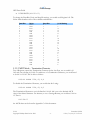
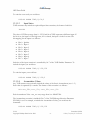
4.6.1 Input State and Satellite Count Mode
In this mode, the Comm LED (Orange) will alternate between Comm Status and Input
Status every 5s. The Comm Status behavior is described in the Install Guides. When
reporting the Input states, it will blink with a single pulse when the input is low and two
pulses when the input is high. After 500mS it reports the next input. The inputs are reported
sequentially starting with Input 0 and finishing with Input 4. For example, if Comm was
acquired, ignition (i.e. input 0) was on and all other inputs were low, you would see the
following pattern:
Figure 5 - Alternate Comm LED Blink Pattern
V1.0.6
Copyright ©CalAmp DataCom Inc 2009
- 21 -
December 10 2009
CalAmp Proprietary & Confidential
LMU Users Guide
For the GPS LED (Yellow) the GPS LED will indicate OFF (LED off), ON (slow blink)
and TIME-SYNC (fast blink) as it always has. When the GPS is acquired, it reports the
number of satellites being tracked by going on for 500mS, off for 500mS and then for each
satellite being tracked, on for 125mS and off for 125 mS. After 5-sec, the pattern repeats.
:For example, an LMU tracking 6 satellites would have a blink pattern similar to the
following:
Figure 6 - Alternate GPS LED Blink Pattern
This mode is enabled by setting bit 3 of S-Register 171.
AT$APP PARAM 1024,51,8,8
To return the LEDs to their normal behavior, you would use:
AT$APP PARAM 1024,51,8,0
4.6.2 Alternate LED Blink Code
This mode also reports input status along with Comm and GPS Status.
The GPS LED will be off if the Ignition is off or if the LMU does not have a GPS fix.
Otherwise, the GPS LED will report the number of satellites by blinking ‘n’ times after a
single long blink. (i.e. similar to the pattern described above).
The COMM LED behavior is a little more complicated.
When the Ignition is off, the COMM LED will blink at a 1Hz rate (1 blink per second).
When the Ignition is on but the LMU does not have Comm and no other inputs are ‘active’,
the COMM LED will blink at a 4Hz rate (1 blink every ¼ of a second).
If the Ignition is on with no other inputs ‘active’ and the LMU does have Comm, the
COMM LED will be solid.
If the Ignition is on and other inputs are 'active', the COMM LED will blink the number of
time corresponding to the first 'active' Input's designation followed by a pause and then the
number of times corresponding to the next 'active' Input's designation.
An 'active' Input is one whose state does not match the corresponding bias setting in S-158.
V1.0.6
Copyright ©CalAmp DataCom Inc 2009
- 22 -
December 10 2009
CalAmp Proprietary & Confidential
LMU Users Guide
For example, let us assume that all inputs are biased low. If Ignition is On, and Inputs 2 and
4 are high then the COMM LED will blink twice, followed by a pause, followed by 4 more
blinks.
This mode is enabled by setting both Bits 3 and 5 of S-Register 171.
To enable this mode, you would use:
AT$APP PARAM 1024,51,40,40
To return the LEDs to their normal behavior, you would use:
AT$APP PARAM 1024,51,40,0
4.6.3 Disabling the Status LEDs
In some installations it may be desirable to disable the status LEDs, for instance when the
installation is covert and drivers/end users should not be able to easily locate the LMU.
Turning the status LEDs off is controlled by bit 3 of S-Register 140. If this bit is set, then
the Comm and GPS LEDs are disabled and turned off. If this bit is cleared, then the Comm
and GPS LEDs will behave as normal.
To disable the LEDs you would use:
AT$APP PARAM 1024,20,8,8
To re-enable them, you would use:
AT$APP PARAM 1024,20,8,0
V1.0.6
Copyright ©CalAmp DataCom Inc 2009
- 23 -
December 10 2009
CalAmp Proprietary & Confidential
LMU Users Guide
4.7 Restoring values through a power cycle
The LMU is capable of storing some of its values to non-volatile memory so that they can be
restored after a power cycle. The following values may be stored:
•
•
•
•
•
The values of all 16 Accumulators
The states of all 16 PEG Flags
The state (inside or outside) of all 32 PEG Zones
Last known GPS position
The current value of the PEG State variable (see PEG Programming Guide for
details)
These values can optionally be saved at two points
•
•
Before a soft reset (i.e. AT$APP QUIT or the Application Restart PEG Action)
On ignition off
This feature is collectively known as an Environment Restore and is controlled by S-Register
127. Bits 0-3 control which values are saved where each bit is associated to a specific value.
If the bit is set, the associated value is saved. If it is cleared, the associated value is not saved.
The bit-mappings for bits 0-3 are as follows:
•
•
•
•
Bit 0 = The values of all 16 Accumulators
Bit 1 = The states of all 16 PEG flags
Bit 2 = The state (inside or outside) of all 32 PEG Zones
Bit 3 = Last known GPS position
Bits 6 and 7 of S-Register 127 control when these values are saved. If bit 6 is set, then the
values are saved on a soft reset. If bit 7 is set, then the values are saved on an ignition off.
For example to save all four values on just ignition off, you would use the following
commands:
Save Accumulators:
AT$APP PARAM 1024,7,1,1
Save PEG flags:
AT$APP PARAM 1024,7,2,2
Save PEG Zones:
AT$APP PARAM 1024,7,4,4
Save the last known GPS position:
AT$APP PARAM 1024,7,8,8
V1.0.6
Copyright ©CalAmp DataCom Inc 2009
- 24 -
December 10 2009
CalAmp Proprietary & Confidential
LMU Users Guide
Do no save on a soft reset:
AT$APP PARAM 1024,7,64,0
Save on ignition off
AT$APP PARAM 1024,7,128,128
V1.0.6
Copyright ©CalAmp DataCom Inc 2009
- 25 -
December 10 2009
CalAmp Proprietary & Confidential
LMU Users Guide
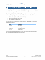
5 Working with External Serial Devices
While all of the LMU products have a host port to allow users to issue AT Commands to
configure, debug and control the device, only the LMU-4100 supports external serial devices
as a peripheral. The one exception is that the LMU-2500 does support the output of NMEA
sentences on its host port.
The CalAmp LMU-4100™ and LMU-2500™ supports three external serial ports for use
with other devices, though only two can be available at the same time. The serial ports are:
•
•
•
The Host Port (LMU-4100™ and LMU-2500™)
The Modem Port (LMU-4100™ only)
The Aux Port(LMU-4100™ only)
To access these ports you would need a specific peripheral. The mapping of serial ports to
peripherals is as follows:
Port
Host Port
Modem Port
Aux Port
Peripheral
Serial Adapter
TetheredLocator Adapter
ioPOD Adapter
Bluetooth Adapter
TetheredLocator Adapter
ioPOD Adapter
The following sections describe how each of these ports can be used. Using serial ports via
the Bluetooth Adapter is described in its own section.
V1.0.6
Copyright ©CalAmp DataCom Inc 2009
- 26 -
December 10 2009
CalAmp Proprietary & Confidential
LMU Users Guide
5.1 Using the Host Port
The Host Port of the LMU-4100™ and LMU-2500™ can be accessed in one of two ways,
either in Host mode, which is meant for use with laptops, and PDAs or MDT mode, which
is meant for use with serial mobile data terminals, bar-code readers, magnetic-card readers
and other ‘dumb’ serial devices. In Host mode, a host device can issue AT Commands,
receive NMEA data or establish a Dial-Up Networking session. In MDT 1 mode, the LMU4100 will act as a message pass-thru for the dumb serial device. That is, it will send any
messages it receives from the serial device to the backend system and vice-versa.
5.1.1 Host Mode - AT Command Setup
To issue AT Commands to the LMU-4100™ or LMU-2500™, you would need some
measure of terminal program such as HyperTerminal. Instructions on how to set
HyperTerminal up for use with the LMU™ can be found in the Appendix D of this
document.
The default settings for the Host port are:
•
•
•
•
115200 BAUD
8 Data Bits
No Parity
1 Stop Bit
The only setting that can be changed is the BAUD rate. This can be done with one of two
AT Commands:
AT+IPR=<baud rate>
ATS148=<value>
The Host port BAUD rate will change instantly after the AT+IPR command is issued. The
LMU™ must be reset for the BAUD rate to change after using the S148 command. Both
changes are non-volatile and thus the BAUD rate will remain unchanged during subsequent
power cycles. The LMU™ supports the following BAUD rates:
BAUD Rate
4800
9600
19200
38400
57600
115200
Default
S148 Value
4
5
7
9
10
12
255
1
MDT stands for Mobile Data Terminal. This mode is also known as Generic Serial Device mode or GSD.
The documentation uses both notations.
V1.0.6
Copyright ©CalAmp DataCom Inc 2009
- 27 -
December 10 2009
CalAmp Proprietary & Confidential
LMU Users Guide
DO NOT use values that are not on this list as it may cause unexpected behaviors within the
LMU.
Changing the BAUD rate setting will have an effect on the NMEA output and the Dial-Up
Networking functions of the Host Port.
5.1.2 Host Mode – NMEA Output
NMEA messages are generally used by in-vehicle navigation applications to plot the current
position of the vehicle and compute real-time driving directions. The LMU-4100™ or LMU2500™ can output several NMEA sentences over its Host Port to support these
applications. The available sentences are:
•
•
•
•
•
•
•
GGA (GPS Fix Data)
GLL (Geographic Position, Latitude / Longitude)
GSA (GNSS 2 DOP and Active Satellites)
GSV (GNSS Satellites in View)
RMC (Recommended Minimum Specific GNSS Data)
VTG (Course Over Ground and Ground Speed)
ZDA (Date and Time)
Please refer to your application’s documentation as to which messages it needs to operate
properly.
S-Register 128 is used to control which messages are sent to the serial port. Each message is
associated with a specific bit of this register. If the bit is set, then the message will be sent to
the host port. If the bit is cleared the message will not be sent. The bit mapping of S-128 is
as follows:
•
•
•
•
•
•
•
Bit 0 – Enable/Disable GGA Message
Bit 1 – Enable/Disable GLL Message
Bit 2 – Enable/Disable GSA Message
Bit 3 – Enable/Disable GSV Message
Bit 4 – Enable/Disable RMC Message
Bit 5 – Enable/Disable VTG Message
Bit 6 – Enable/Disable ZDA Message
For example, to enable the GGA and RMC messages you could use:
ATS128=17
Alternatively you could use two Parameter commands:
Turn on GGA
2
Global Navigation Satellite System, which could refer to GPS, GLONASS, Galileo, etc…
V1.0.6
Copyright ©CalAmp DataCom Inc 2009
- 28 -
December 10 2009
CalAmp Proprietary & Confidential
LMU Users Guide
AT$APP PARAM 1024,8,1,1
Turn on RMC
AT$APP PARAM 1024,8,16,16
5.1.3 Host Mode – Dial-Up Networking
The LMU-4100’s™ Host Port can be used by a laptop or PDA to establish a Dial-Up
Networking session. This is to allow the laptop or PDA access to the Internet to enable such
applications as email and web-browsing.
There are two basic steps to accomplish this:
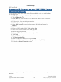
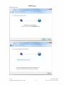
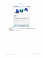
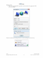
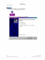
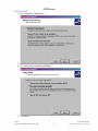
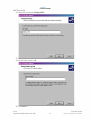
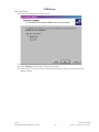
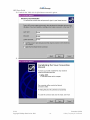
1. Install a modem driver
2. Create the Dial-Up Networking session
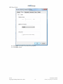
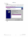
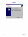
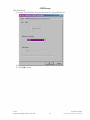
The details on each of these steps are described in the Adding a Modem Driver and Creating
a Dial-Up Networking Session Appendixes of this document.
Depending on the wireless networking technology employed by the LMU-4100, there are
several other steps you should take to ensure uninterrupted operation.
5.1.3.1 Disable Connection Monitoring
The Connection Monitor is used by the LMU-4100™ to ensure that the data session with
the wireless modem is still valid. In some cases, this may reduce the stability of Dial-Up
Networking session. The connection monitor is controlled by two S-Registers, 152 and 154.
S-Register 152 should be set to 0 and for S-Register 154 bit 2 should be cleared and bit 3
should be set. The two commands you would use to accomplish this are:
ATS152=0
AT$APP PARAM 1024,34,12,8 3
Please note that the connection monitor is described in detail later in this document.
5.1.3.2 Disable Network Status Queries
For the Kyocera based CDMA LMU-4100™ it is advisable to disable any KMIP 4 polling, as
any missed KMIP messages may cause the LMU to reset the modem. A modem reset would
then cause the Dial-Up Networking session to be torn down. KMIP polling is controlled by
S-Register 153. To disable KMIP polling you would use:
ATS153=0
3
One question that may arise is why not use ATS154=8 instead of the PARAM command. The basic
answer is so that we do not interfere or change any settings we do not absolutely need to. We will make
heavy use of parameter bit masking through-out this document for that reason.
4
KMIP is a protocol the LMU-4100 uses to talk to the Kyocera M200 CDMA modem. It is used to pull
modem information such as carrier id and RSSI.
V1.0.6
Copyright ©CalAmp DataCom Inc 2009
- 29 -
December 10 2009
CalAmp Proprietary & Confidential
LMU Users Guide
To re-enable KMIP polling you would use:
ATS153=10
KMIP Polling is described in detail later in this document.
5.1.3.3 Bypass Mode
Bypass mode, in reference to Dial-Up Networking applies to just the CDMA LMU-4100™.
In this mode, the LMU switches itself out of the data path and allows the host laptop or
PDA to establish the Dial-Up Networking session directly with the CDMA modem. This
occurs automatically when the Host Port BAUD rate and the Modem Port BAUD rate are
set to the same value. The Host Port BAUD rate is controlled by S-148 and the Modem Port
BAUD rate is controlled by S-146.
V1.0.6
Copyright ©CalAmp DataCom Inc 2009
- 30 -
December 10 2009
CalAmp Proprietary & Confidential
LMU Users Guide
5.1.4 MDT Mode
MDT Mode allows a dumb serial device to pass messages through the LMU-4100™ or the
LMU-2500™ to the back-end system using LM Direct User Messages. The backend system
may also send a User Message to the LMU, the contents of which should be forwarded to
the serial device.
MDT mode can be enabled on either the Serial Adapter peripheral or on the ioPOD
peripheral by means of a jumper.
The Host Port’s MDT mode settings are controlled by S-Registers 130 thru 138 and SRegister 141.
5.1.4.1 MDT Sub-Modes – LMU-4100™
The Host Port’s MDT mode supports two sub-modes, Generic Serial Device Mode and
Long Message Mode.
In Generic Serial Device mode, the LMU-4100™ will accept only single messages from the
generic serial device that are 804 bytes in length or less. Any excess data received will be
truncated. The LMU will package all 804 bytes in a single user message.
In Long Message Mode, the LMU-4100™ will break-up messages longer than 804 into
multiple User Messages. Each User Message will contain up to 804 bytes of data. It is up to
the receiving application (i.e. the backend) to re-assemble the original message from each of
the user messages.
In either mode, the backend system can only send messages to the LMU of 848 bytes or less.
Which mode is in use is controlled by S-Register 130. A value of 1 enables Generic-Serial
Device Mode and a value of 2 enables Long Message Mode. All other values are undefined
and should not be used. That is, to enable Generic Serial Device mode you would use:
ATS130=1
To enable long message mode you would use:
ATS130=2
5.1.4.2 MDT Modes – LMU-2500™
The LMU-2500™ only supports the Generic Serial Device mode. This mode is enabled by
setting S-Register 130 to 129. In this mode the LMU-2500™ will be in Host Port mode for
the first 30s after power up. After that, the LMU-2500™ switches to Generic Serial Device
mode. After a wake-up, the LMU-2500™ immediately enters Generic Serial Device mode.
To enable Generic Serial Device mode on the LMU-2500™, you would use:
ATS130=129
V1.0.6
Copyright ©CalAmp DataCom Inc 2009
- 31 -
December 10 2009
CalAmp Proprietary & Confidential
LMU Users Guide
To disable this mode, you would use:
ATS130=0
5.1.4.3 MDT Mode – Serial Port settings
The MDT Mode serial port settings are independent from the Host Port Host Mode
settings. The MDT mode settings are controlled by 2 S-Registers, 131 and 132. These
register control the BAUD Rate, Data Bits, Parity and Stop Bits settings for MDT mode.
These changes do not affect the settings of S-148 or the +IPR command (i.e. the host port
baud rate).
The MDT mode BAUD Rate is controlled by S-Register 131 and supports the following
data rates:
•
•
•
•
•
•
4800 BAUD (ATS131=4)
9600 BAUD (ATS131=5)
19200 BAUD (ATS131=7)
38400 BAUD (ATS131=9)
57600 BAUD (ATS131=10)
115200 BAUD (ATS131=12)
To change the Data Bits, Parity and Stop Bit settings, you would use S-Register 132. The
follow table describes each of the available combinations:
Data Bits
8
8
8
8
8
8
7
7
7
7
7
7
6
6
6
6
6
6
5
5
5
5
5
5
Parity
None
None
Even
Even
Odd
Odd
None
None
Even
Even
Odd
Odd
None
None
Even
Even
Odd
Odd
None
None
Even
Even
Odd
Odd
V1.0.6
Copyright ©CalAmp DataCom Inc 2009
Stop Bits
2
1
2
1
2
1
2
1
2
1
2
1
2
1
2
1
2
1
2
1
2
1
2
1
- 32 -
S-132 Setting
7
3
31
27
15
11
6
4
30
26
14
10
5
1
29
25
13
9
4
0
28
24
12
8
December 10 2009
CalAmp Proprietary & Confidential
LMU Users Guide
5.1.4.4 MDT Mode – Termination Character
The LMU-4100™ and LMU-2500™ can optionally detect a ‘Termination Character’ in the
data sent from the serial device over the MDT port. This character is meant to denote the
end of the message and that LMU should send the contents to the back-end system.
The Termination Character is meant for use when the serial device is sending ASCII
encoded text. When using serial devices that produce binary messages, it is best not to use a
Termination Character.
Two S-Registers control the Termination Character, one to enable it (S-133) and one to
define it (S-134).
To enable use of a Termination Character, you would need to set bit 2 of S-133. This is done
as follows:
AT$APP PARAM 1024,13,4,4
To disable the Termination Character, you would clear bit 2 using:
AT$APP PARAM 1024,13,4,0
The Termination Character to use is defined in S-134. S-134 is set to the decimal ASCII
value of the desired character. For instance, to use a Carriage Return, you would set S-134 to
13. That is:
ATS134=13
An ASCII chart can be found in Appendix C of this document.
5.1.4.5 MDT Mode – Message Termination Length
As an alternative to using a Termination Character, the LMU can be configured to send User
Messages based on the amount of data it receives from the serial device. That is, the LMU
will buffer a certain number of bytes and once it reaches the limit it will package the entire
buffer into a User Message and send it to the back-end system. The size limit of the buffer is
defined by S-Register 135. The value of S-135 is scaled in 4 byte increments up to a
maximum 804 bytes. The range of S-135 is therefore 1-201. For instance, to package 200
byte User Messages you would use:
ATS135=50
By setting the value of S-135 to 0 disables the termination length feature.
5.1.4.6 MDT Mode – Message Termination Timeout
The last option to define when to build a User Message is the Termination Timeout. In this
case, the LMU will collect data from the serial device for a specific period of time. When
that time has elapsed, the LMU will package the data into a User Message and send it to the
V1.0.6
Copyright ©CalAmp DataCom Inc 2009
- 33 -
December 10 2009
CalAmp Proprietary & Confidential
LMU Users Guide
back-end system. Please note that the LMU will still obey its maximum buffer size (804
bytes) even if the Termination Length is undefined.
The Termination Timeout is controlled by S-Register 138 and ranges from 1 to 255ms.
For instance, to set the timeout for 120ms you would use:
ATS138=120
Like the Termination Length, setting S-register 138 to 0 will disable the Termination
Timeout feature.
5.1.4.7 MDT Mode – User Message ID
The User Message ID field serves two purposes for User Messages. First, the LMU will tag
any inbound (LMU to server) User Messages with the defined Message ID. This will appear
in the User Message ID field of the LM Direct packet. The second function is to act as a
filter on any outbound (server to LMU) User Messages. If the outbound User Message does
not have the same ID as the LMU, then the contents of the User Message will not be sent to
the serial device. The Message Received PEG Trigger however, will work regardless of
matching User Message IDs.
The Message ID can range from 0 to 255 and is defined in S-Register 136. For instance, to
define a User Message ID of 4, you would use:
ATS136=4
This feature is always enabled, so it is very important to co-ordinate this setting with
whoever is responsible for your LM-Direct implementation.
5.1.4.8 MDT Mode – Message Disposition
The message disposition defines how the LMU’s log will handle the User Messages. There
are six options:
•
•
•
•
•
•
Attempt to send the User Message immediately. The message will be logged if the
send fails or if the log is already active.
Immediately log the User Message
Immediately send the User Message using the Unacknowledged service and place a
copy in the LMU’s log. (i.e. Priority Message)
Send the User Message using the Unacknowledged service (i.e. message is never
logged)
Route the User Message (contents only) to the SMS Destination Address
Route the User Message (contents only) to the last phone number of an incoming
SMS message
With the last two options the contents of any incoming SMS messages will be routed to the
serial device.
V1.0.6
Copyright ©CalAmp DataCom Inc 2009
- 34 -
December 10 2009
CalAmp Proprietary & Confidential
LMU Users Guide
The message disposition is controlled by S-Register 137. The settings are as follows:
•
•
•
•
•
•
1 or 2 = Send Message, Log if Send Fails
3 = Log Message
4 = Priority Message
5 = Unacknowledged Message
7 = Route Incoming (Client to LMU) SMS messages to the host serial port. Route all
User Messages to the SMS Destination Address
8 = Route Incoming (Client to LMU) SMS messages to the host serial port. Route all
User Messages to the last phone number that sent the LMU a message
5.1.4.9 MDT Mode – Message Count Limit
The Message Count Limit is a means of controlling how much data is sent as User Messages.
It was specifically designed for cases where the same message is repeated often by the serial
device, for instance, a meter that provides a reading every 10s. The Count Limit allows the
LMU to ignore a certain number of these messages before creating a User Message. That is,
the LMU will ignore X-1 messages and create a User Message around the X message. X is
defined by S-Register 141. The lower 7 bits of S-141 define the message count. Bit 7 defines
the scaling. If bit 7 is set, the value in bits 0-6 is scaled by 100. This means that there are two
supported ranges, 0 – 127 messages and 100 to 12700 messages. For example, to filter out 50
messages you would use:
ATS141 = 50
To filter out 500 messages you would use:
ATS141 = 133
V1.0.6
Copyright ©CalAmp DataCom Inc 2009
- 35 -
December 10 2009
CalAmp Proprietary & Confidential
LMU Users Guide
5.2 Using the Aux Port
The Aux Port on the ioPOD can be used for one of two purposes, it can either be a source
for NMEA messages, or it can act as an MDT port. The mode of the Aux Port is controlled
by S-Register 160. If bit 0 of this register is cleared, then the port is setup for MDT mode. If
bit 0 is set, then the port is set up for NMEA mode (bit 0 is set).
For MDT mode you would use:
AT$APP PARAM 1024,40,1,0
For NMEA mode you would use:
AT$APP PARAM 1024,40,1,1
5.2.1 NMEA Mode
The Aux port’s NMEA mode supports two NMEA messages, the GGA message and RMC
message. The GGA message is automatically enabled when NMEA mode is enabled. To
turn on the RMC message, you would use bit 4 of S-160. To turn the RMC message on, you
would set bit 4. That is:
AT$APP PARAM 1024,40,16,16
The RMC message is disabled by clearing bit 4.
AT$APP PARAM 1024,40,16,0
5.2.2 MDT Mode
The Aux port’s MDT mode is identical to the MDT mode of the Host Port. That is, you
may connect a serial device to the Aux port and be able to receive User Messages sent from
the serial device at your back-end system. The available settings for the Aux Port are similar
to those of the Host Port, so we only discuss the Aux Port’s settings below.
5.2.2.1 MDT Mode – Serial Port settings
The Aux port’s MDT mode serial settings are controlled by 2 S-Registers, 161 and 162.
Using these registers, a user can change the BAUD Rate, Data Bits, Parity and Stop Bits
settings for MDT mode.
The MDT mode BAUD Rate is controlled by S-Register 161 and supports the following
data rates:
• 4800 BAUD (ATS161=4)
• 9600 BAUD (ATS161=5)
• 19200 BAUD (ATS161=7)
• 38400 BAUD (ATS161=9)
• 57600 BAUD (ATS161=10)
V1.0.6
Copyright ©CalAmp DataCom Inc 2009
- 36 -
December 10 2009
CalAmp Proprietary & Confidential
LMU Users Guide
• 115200 BAUD (ATS161=12)
To change the Data Bits, Parity and Stop Bit settings, you would use S-Register 162. The
follow table describes each of the available combinations:
Data Bits
8
8
8
8
8
8
7
7
7
7
7
7
6
6
6
6
6
6
5
5
5
5
5
5
Parity
None
None
Even
Even
Odd
Odd
None
None
Even
Even
Odd
Odd
None
None
Even
Even
Odd
Odd
None
None
Even
Even
Odd
Odd
Stop Bits
2
1
2
1
2
1
2
1
2
1
2
1
2
1
2
1
2
1
2
1
2
1
2
1
S-162 Setting
7
3
31
27
15
11
6
4
30
26
14
10
5
1
29
25
13
9
4
0
28
24
12
8
5.2.2.2 MDT Mode – Termination Character
Two S-Registers control the Termination Character for the Aux Port, one to enable it (S163) and one to define it (S-164). To enable use of a Termination Character, you would need
to set bit 2 of S-163. This is done as follows:
AT$APP PARAM 1024,43,4,4
To disable the Termination Character, you would clear bit 2 using:
AT$APP PARAM 1024,43,4,0
The Termination Character to use is defined in S-164. S-164 is set to the decimal ASCII
value of the desired character. For instance, to use a Carriage Return, you would set S-164 to
13. That is:
ATS164=13
An ASCII chart can be found in Appendix C of this document.
V1.0.6
Copyright ©CalAmp DataCom Inc 2009
- 37 -
December 10 2009
CalAmp Proprietary & Confidential
LMU Users Guide
5.2.2.3 MDT Mode – Message Termination Length
The Message Termination Length for the Aux port is defined by S-Register 165.
The value of S-165 indicates how many bytes to make the message. The value may range
from 1 to 201 giving a byte range of 4 to 804 bytes. For instance, to set a Message
Termination Length of 200 bytes you would use:
ATS165=50
Setting the value of S-165 to 0 disables the Termination Length feature.
5.2.2.4 MDT Mode – Message Termination Timeout
The Termination Timeout for the Aux Port is controlled by S-Register 168 and ranges from
1 to 255ms. For instance, to set the timeout for 120ms you would use:
ATS168=120
Like the Termination Length, setting this S-Register to 0 will disable the Termination
Timeout feature.
5.2.2.5 MDT Mode – User Message ID
The User Message ID field serves two purposes; first, the LMU will tag any inbound (LMU
to server) User Messages with the defined Message ID. This will appear in the User Message
ID field of the LM Direct packet. The second function is to act as a filter on any outbound
(server to LMU) User Messages. If the outbound User Message does not have the same ID
as the LMU, then the message will not be sent to the serial device. The Message Received
PEG Trigger however, will work regardless of matching User Message ID.
The Aux Port’s Message ID can range from 0 to 255 and is defined in S-Register 166. For
instance, to define a User Message ID of 44, you would use
:
ATS166=44
This feature is always enabled, so it is very important to co-ordinate this setting with
whoever is responsible for your LM-Direct implementation.
It is also important to note that the LM Direct packet must indicate which port (Host or
Aux) the message should be sent to. Please refer to the LM Direct Reference Guide for
details. In general, it is good practice not to use the same value for the User Message ID on
the Host Port as is used on the Aux Port. At very least this will help the LM Direct server
determine which port was the source of the User Message.
5.2.2.6 MDT Mode – Message Disposition
The Message Disposition defines how the LMU will deal with the User Message. There are
four options:
V1.0.6
Copyright ©CalAmp DataCom Inc 2009
- 38 -
December 10 2009
CalAmp Proprietary & Confidential
LMU Users Guide
• Attempt to send the User Message. If the message cannot be sent, or the log is
already active, the User Message is logged.
• Immediately log the User Message
• Route the User Message (contents only) to the SMS Destination Address
• Route the User Message (contents only) to the last phone number of an incoming
SMS message
With the last two options the contents of any incoming SMS messages will be routed to the
serial device.
The Message Disposition is controlled by S-Register 167. The settings are as follows:
•
•
•
•
1 or 2 = Send Message, Log if Send Fails
3 = Log Message
7 = Route Incoming (Client to LMU) SMS messages to the Aux Serial Port. Route all
User Messages to the SMS Destination Address
8 = Route Incoming (Client to LMU) SMS messages to the Aux Serial Port. Route all
User Messages to the last phone number that sent the LMU a message
5.2.2.7 MDT Mode – Message Count Limit
The Message Count Limit for the Aux port is defined by S-169. Unlike the Host Port, the
Aux Port limit does not offer a scaling option and therefore only ranges from 0-255
messages. For example, to send every 10th message received on the Aux Port, you would use:
ATS169=10
To send every 150th message, you would use:
ATS169=150
V1.0.6
Copyright ©CalAmp DataCom Inc 2009
- 39 -
December 10 2009
CalAmp Proprietary & Confidential
LMU Users Guide
5.3 Using The Garmin NUVI or MacKenzie Labs DAD-A1214
The LMU-4100 also supports messaging for two specific serial devices, the Garmin NUVI
and the MacKenzie Labs DAD-A1214. For which messages are supported for each device,
please refer to the PEG Programming Guide.
Both the device selection and which port the device is connected to are dictated by SRegister 173. The lower 4 bits dictate the device and the upper 4 bits dictate the destination
port. The bit mappings are as follows:
• Bits 5 and 7 – These bits define which serial port the canned message is sent to. The
options are:
o 0 = Host Port
o 1 = Modem Port
o 2 = Aux Port
o 3-31 = Reserved
• Bits 0 and 4 – These bits define which device the LMU is connected to. The options
are:
o 1 = Mackenzie LABs DADS-A1214
o 2 = Garmin NUVI
o 0,3-31 = Reserved
For example, to use the DADS-A1214 on the Aux Port, you would use:
ATS173=65 (0x41)
To use the Garmin NUVI on the Host Port, you would use:
ATS173=2 (0x02)
V1.0.6
Copyright ©CalAmp DataCom Inc 2009
- 40 -
December 10 2009
CalAmp Proprietary & Confidential
LMU Users Guide
5.4 Using the Modem Port
An external Modem Port is only available when using the TetheredLocator adapter.
Otherwise, the Modem Port is assumed to be connected to the LMU’s internal modem.
Using the external Modem Port allows users to connect an LMU to an existing modem or
phone via a serial connection. The LMU should then be able to use the phone or modem’s
Dial-Up Networking capabilities to establish a data session.
When working with an external modem, there are five settings you must keep in mind:
• The modem driver in use.
• The modem port’s BAUD rate
• The packet dial string
• The network username
• The network password
5.4.1 Selecting a Modem Driver
The modem driver the LMU will use is defined by S-Register 120 or S-Register 150,
depending on which Comm Profile is in use. Comm Profiles are discussed below. This
register should only be changed when using the TetheredLocator adapter, or when directed
by CalAmp personnel.
The available external modem drivers are:
• 128 – Generic 19200 BAUD, ATDT 0, No Status
• 131 – iDEN - Motorola iDEN devices, 38400 BAUD, ATD0, RALP Status
• 133 – GSM/GPRS – WaveCom, 57600 BAUD, ATDT*99***#1, WMUX Status
• 134 – GSM/GPRS – Generic, 57600 BAUD, ATDT *99***#1, no Status
• 136 – TAIP Modem – 9600 BAUD, TAIP string sent directly to modem Serial port
• 137 – No Modem
• 139 – CDMA - Kyocera M200, 57600 BAUD, ATD#777, KMIP Status
• 140 – CDMA – Generic- 57600 BAUD, ATD#777, No Status
• 141 – TDMA - Sony Ericsson DM25, 9600 BAUD, (SMS Only), no Status
• 142 – iDEN – Motorola iDEN devices, 57600 BAUD, ATDT 0, CMUX Status
• 143– GSM/GPRS – Siemens, 115200 BAUD, ATD*99***1#, PPP, Siemens
• 144 – Iridium Data modem
The available internal modem drivers are:
•
•
•
•
•
•
3 – iDEN LMU-4100 (TC990569)
11 – CDMA LMU-4100 (Kyocera M200)
14 – iDEN LMU (TC990599)
15 – GPRS LMU-4100
17 – CDMA LMU-4100 (WaveCom Q2438)
18 – GPRS LMU (Cinterion MC55)
V1.0.6
Copyright ©CalAmp DataCom Inc 2009
- 41 -
December 10 2009
CalAmp Proprietary & Confidential
LMU Users Guide
The first value indicates what the S-120 setting should be. For example to use a generic
CDMA modem driver you would use:
ATS120=140
If you are unsure of what driver you should use for your external device, pick the generic
one (ATS120 = 128) as it can be adapted to most network technologies.
5.4.2 Configuring the Modem Port’s BAUD Rate
Like the Host Port, the Modem Port only allows users to change the BAUD rate settings.
The Data Bits are always set to 8, there is always 1 Stop Bit, and always no Parity. The
BAUD rate is controlled by S-Register 146. The available settings are:
•
•
•
•
•
•
•
4=4800
5=9600
7=19200
9=38400 (Default iDEN)
10=57600
12= 115200 (Default GPRS & CDMA)
255 = use default
In general, you can usually set this S-Register to use the technology default value (i.e.
ATS146=255) as the LMU will attempt to automatically detect and change the current
BAUD rate of the external phone or modem.
5.4.3 Setting the dial string
The Dial String is effectively the phone number a host device, such as the LMU, would use
to establish a Dial-Up Networking session with the external phone or modem. In most
cases, the external phone or modem will use a technology specific value.
•
•
•
CDMA 1xRTT Dial String = #777
GPRS Dial String = *99***1#
iDEN Dial String = 0
The Dial String is controlled by Parameter 2316. For example to use a CDMA dial string,
you would enter the following AT Command:
AT$APP PARAM 2316,0,”#777”
One important thing to note for GPRS devices is that the LMU will not program the APN
settings into the external phone or modem. It is assumed that the APN settings have been
pre-configured by the provider of the phone or modem.
V1.0.6
Copyright ©CalAmp DataCom Inc 2009
- 42 -
December 10 2009
CalAmp Proprietary & Confidential
LMU Users Guide
5.4.4 Setting the network username and password
For some networks, the operator may require that a username and password be supplied
before the device is allowed to establish a data session with the network. The LMU can be
programmed to supply these values as part of the Dial-Up Networking negotiations. The
username is controlled by Parameter 2314 and the password is contained in Parameter 2315.
For instance, to set a username and password combination of ‘dummy’/’dummy’ you would
use:
AT$APP PARAM 2314,0,”dummy”
AT$APP PARAM 2315,0,”dummy”
Be advised that some usernames and passwords can be case sensitive, that is ‘Dummy’ is a
different username than ‘dummy’. Be sure you enter the values as they were provided to you
by your network operator otherwise the LMU might not be able to establish a data session.
V1.0.6
Copyright ©CalAmp DataCom Inc 2009
- 43 -
December 10 2009
CalAmp Proprietary & Confidential
LMU Users Guide
6 Using the CalAmp Bluetooth Adapter
(BTA)
The LMU-4100™ supports Bluetooth functionality using the CalAmp Bluetooth Adapter
(BTA) (Part Number TC1106-9). The LMU-4100™ can be configured to use the BTA as its
Host port able to either initiate or accept the Bluetooth connection to the other device(s).
The Bluetooth adapter has three parameters associated with it.
• Parameter 2080 – Bluetooth Name:
This Parameter contains a string which is compared to the remote device names
during a scan. If this string is found within the name of a remote device the BTA
will attempt to connect to that device. If this string is empty, all remote device
names will be eligible for connection.
• Parameter 2081 – Bluetooth PIN:
The PIN is effectively the password one Bluetooth device uses to access another.
When the LMU-4100™ initiates the connection, this should be the PIN of the
remote device. When the LMU-4100™ is accepting the connection, this is the value
the connecting device should use.
• S-Register 170 – BlueLocator Configuration Settings:
This is another bit mapped S-Register with the following controls:
o Mode Control (bits 0 and 1)
The BTA supports two modes, Off, and Host Port. A value of 0 is off, and a
value of 1 sets the BTA up as a Host Port. 2 and 3 are not defined and
should never be used.
o Discoverable (bit 2)
Discoverable means that the LMU-4100™ will be visible to other Bluetooth
devices when they perform a scan. Setting bit 2 enables discovery, clearing it
disables discovery.
o Initiator/Acceptor (bit 3)
This function controls if the LMU-4100™ will attempt the Bluetooth
connection (Initiator) or if it will wait for a device to connect to it
(Acceptor). If bit 3 is set, the LMU-4100™ will act as an initiator, if it is
cleared, the LMU-4100 will act as an acceptor.
o Profile (bit 4)
The BTA supports two Bluetooth profiles, the Serial Port Profile or the DialUp Networking profile. This setting applies to both the host port and
modem port modes. 5 If bit 4 is set, the LMU-4100™ will present the Dial
Up Networking Profile, if it is cleared, the LMU-4100™ will present the
Serial Port Profile.
o Security Mode (bit 5)
The BTA supports a high and low security mode. In the high security mode,
the connecting device must supply the PIN every time it connects to the
BTA. In low security mode, it is only provided on the initial connection.
5
For older versions of the Bluetooth Adapter, this setting only applied when the BTA was acting as the
modem port.
V1.0.6
Copyright ©CalAmp DataCom Inc 2009
- 44 -
December 10 2009
CalAmp Proprietary & Confidential
LMU Users Guide
Setting bit 5 will place the BTA in low security mode, clearing it will use high
security mode.
6.1 Using the BTA as the Host Port
When acting as a host port, the LMU-4100™ and newer BTA will actually present three
ports:
•
•
•
Port 1 which is used for NMEA output using a Serial Port Profile
Port 2 which is used as the primary Serial Port Profile or Dial-Up Networking profile
Port 3 which is used for AT Commands and Debug output.
Please note that for some host devices, all three of these ports may not be visible.
Older BTAs will present only a single port using the profile selected by Bit 4 of S170. Each
of the above functions (NMEA, Dial-Up Networking and AT Commands/Debug) can be
performed over this port, but only one can be handled at a time.
6.1.1 NMEA Output
The NMEA Output is separated from the other functions on Port 1 so each may be run
simultaneously.
In this case, users must simply setup S128 to reflect the desired NMEA messages. For
example, to export the NMEA RMC and GGA messages, users would use:
ATS128=5
Note that you do not need to worry about the BAUD rate or the profile in use. Port 1
(NMEA) always makes use of the Serial Port Profile and the BAUD rates are handled by
Bluetooth.
When you pair to the BTA, be sure to select the NMEA port (or first serial port profile) to
connect to this function.
6.1.2 AT Command and Debug Output
Like the NMEA feature, the AT Command and Debug output is separated from the other
Bluetooth features on Port 3. This means that you can issue AT Command while the
Bluetooth Adapter is providing NMEA data and while it is acting as a modem.
To setup, the LMU-4100™ to allow debug output, you will just need the following:
•
•
•
BTA is used as a Host port (1)
BTA needs to be discoverable (bit 2 = 1)
BTA will act as an acceptor (bit 3 = 0)
ATS170=5
V1.0.6
Copyright ©CalAmp DataCom Inc 2009
- 45 -
December 10 2009
CalAmp Proprietary & Confidential
LMU Users Guide
Again, we do not need to worry about the profile or BAUD rate settings.
When you pair to the BTA, be sure to select the Debug port (or last serial port profile) to
connect to this function. Please note that this function may not be available on all
connecting devices.
6.1.3 Dial-Up Networking – Dial-Up Networking Profile
The newer BTAs support a separate Dial-Up Networking port for use with the Dial-Up
Networking profile. To use this profile, the following settings are recommended:
•
•
•
•
•
The BTA should act as the Host Port (bits 0 and 1 = 1)
The BTA should be discoverable (bit 2 = 1)
The BTA will act as the acceptor (bit 3 = 0)
The BTA will use the Dial-Up Networking profile (bit 4 = 1)
The BTA will use Low Security mode (bit 5 = 1)
This should give us the following setup command:
ATS170=53
When pairing to the BTA, be sure to select the Dial-Up Networking port.
6.1.4 Dial-Up Networking – Serial Port Profile
The newer BTAs use a separate port for Dial-Up Networking via a Serial Port Profile. Like
the older BTAs, users will need to add a new serial modem to your laptop or PDA’s driver
list. Please refer to the Modem Driver appendixes for details.
The setup of the newer BTAs is as follows:
•
•
•
•
•
The BTA should act as the Host Port (bits 0 and 1 = 1)
The BTA should be discoverable (bit 2 = 1)
The BTA will act as the acceptor (bit 3 = 0)
The BTA will use the Serial Port profile (bit 4 = 0)
The BTA will use Low Security mode (bit 5 = 1)
This should give us the following setup command:
ATS170=53
V1.0.6
Copyright ©CalAmp DataCom Inc 2009
- 46 -
December 10 2009
CalAmp Proprietary & Confidential
LMU Users Guide
7 Working with Comm
Comm. refers to any features of the LMU that have something to do with the behavior of its
wireless modem. This section is intended to cover the Comm related features not discussed
in the Activating the CalAmp LMU sections found in the LMU Installation Guides.
7.1 Using a second Comm profile
The Comm profile is the set of parameters the LMU needs to access the wireless network. A
profile consists of four values, the Packet Dial-String (Parameter 2316), the network
username (Parameter 2314), the network password (Parameter 2315) and the modem driver
to use (S-120 or S-150). The first Comm. profile is defined when you activate the LMU. That
is, the LMU will use the default Packet Dial String and the supplied username and password.
These initial values are stored in index 0 of the Dial-String, username and password
Parameters. When using Comm Index 0, the LMU will make use the modem driver defined
in S-Register 120.
The second Comm. profile is stored in index 1 of the Dial-String, username and password
Parameters and makes use of S-Register 150 for the modem driver. The LMU can be
commanded to use this second profile in one of two ways, either controlled via PEG, or
controlled by changing the Packet Dial-String-Current Index Parameter (Parameter 2317).
For instance, say you have tethered an Iridium data modem to your LMU which is to be
used when the internal modem does not have coverage. For this example, the Iridium device
uses a Dial-Up Networking phone number of 6195551000. The following commands would
set-up the second Comm Profile for use with the Iridium device.:
ATS150=144
AT$APP PARAM
AT$APP PARAM
AT$APP PARAM
AT$APP PARAM
2316,1,6195551000
2314,1,”dummy”
2315,1,”dummy”
2317,0,1
7.2 GPRS context switching
In the same lines as using a second Comm profile, the LMU can use a second GPRS
Context setting. The LMU has the added ability to automatically switch which Context it
uses. This switching will occur after a certain number of failures when attempting to dial the
GPRS network.
The GPRS Context values are stored in parameter 2306. Keep in mind that the format of the
Context string changes depending which device you are using. For the LMU-4100 the
Context command would look like:
AT$APP PARAM 2306,0,”IP:myapn.myoperator.com”
For the LMU-1000 it would look like:
AT$APP PARAM 2306,0,”myapn.myoperator.com”
V1.0.6
Copyright ©CalAmp DataCom Inc 2009
- 47 -
December 10 2009
CalAmp Proprietary & Confidential
LMU Users Guide
Up to two Contexts can be defined. The first Context is stored in index 0 of parameter 2306,
the second is stored in index 1.
Which Context the LMU will initially use is controlled by the GPRS Context – Current
Index Parameter (2307). If the value of this Parameter is 0, the LMU will start with the first
Context, if the value is 1 it will start with the second. For instance, to use the second Context
you would use:
AT$APP PARAM 2307,0,1
The automatic switching of the active Context is controlled by S-Register 129. This register
defines how many connection attempts the LMU is allowed to make before it automatically
switch to the next Context. A failure is indicated by a Comm Disconnect PEG event and/or
debug message on the host port.
For example, to set a failure count of 5 you would use:
ATS129=5
In this case, if the LMU was using the first Context it would allow 5 connection failures
before switching to the second. If it fails 5 times on the second, it will switch back to the
first.
The automatic switching feature is disabled if S129 is set to 0. By default, S129 is set to 3.
7.3 Automatically resetting the wireless modem
The LMU can automatically reset its internal wireless modem based on a variety of
conditions. Please keep in mind that these features only apply to the LMU-4100.
7.3.1 Send fail restart
In some cases it may be desirable to automatically reset the wireless modem based on its
inability to send in PEG event reports. This is controlled by the Send Fail Restart Count,
which is stored in S-Register 149. If the LMU attempts to send in an event report more than
the number of times indicated in S-149, the LMU will automatically reset the wireless
modem. A send failure occurs at the following stages:
•
•
when the inbound retry schedule (Ignition on or off) expires
when a log send retry interval expires
For instance, to reset the wireless modem after 8 send failures you would use:
ATS149=8
To disable this feature, set S149 to 0.
V1.0.6
Copyright ©CalAmp DataCom Inc 2009
- 48 -
December 10 2009
CalAmp Proprietary & Confidential
LMU Users Guide
7.3.2 Log activity restart
This feature is similar to the Send Fail Restart, only it is time based instead of packet delivery
based. In this case, the LMU will reset the wireless modem if the LMU’s log space has been
active for a specific period of time. This period is defined by S-Register 157 and is stored in
minutes. This timer starts when the LMU’s log goes active and reset when it empties. As an
example, if we want to reset the LMU’s wireless modem if the log has been active for 30
minutes we would use:
ATS157=30
It is highly advisable to set this value to something greater than the length of time it takes the
LMU to empty a full log. This can be around 20 minutes depending on the wireless
technology employed.
7.3.3 Connection monitoring
The LMU’s Connection Monitor is a third means to automatically reset the LMU’s wireless
modem. In this case, the LMU issues a heartbeat message to the wireless modem in the form
of an LCP Echo. If the modem does not respond to three consecutive LCP Echo requests,
the LMU will reset the modem. LCP Echoes are sent in two instances; either on a periodic
basis or after each LM Direct packet is sent. Please keep in mind that LCP Echoes should
only be used with modems that locally maintain a PPP session with the LMU. That is, any
device that uses CDMA 1xRTT or a circuit switched session for its data connection MUST
NOT use the Connection Monitor 6. Doing so may violate the network terms of service
and/or add significant cost to your wireless data charges.
There are three settings that control the Connection Monitor, one which controls how often
the LCP Echo is sent, one that controls the LCP Echo sent after LM Direct packets and one
that is a master enable/disable control. The LCP Echo interval is controlled by S-Register
152. The value of this Register is the length of time, in seconds between LCP Echoes. For
instance, to use a 20 second interval, the AT Command would be:
ATS152=20
Setting value S-152 to 0 disables the periodic LCP Echo.
The sending of LCP Echoes after LM Direct packets is controlled by bit 2 of S-154. To
enable the sending of LCP Echoes, you would set this bit. That is:
AT$APP PARAM 1024,34,4,4
To disable the sending of LCP Echoes after LM Direct packets, you would clear bit 2 using:
AT$APP PARAM 1024,34,4,0
6
The Connection Monitor is always disabled for both the internal and external CDMA modem drivers
regardless of LMU settings.
V1.0.6
Copyright ©CalAmp DataCom Inc 2009
- 49 -
December 10 2009
CalAmp Proprietary & Confidential
LMU Users Guide
The master enable/disable setting is controlled by bit 3 of S-Register 154. Setting this bit will
disable the Connection Monitor, clearing it will enable monitoring. To enable the Monitor
you would use:
AT$APP PARAM 1024,34,8,0
To disable it, you would use:
AT$APP PARAM 1024,34,8,8
When using the LMU to establish a Dial-Up Networking session with a laptop or PDA, it is
best to disable the Connection Monitor.
7.3.4 Querying the modem for network status
The LMU periodically polls the modem for network status to populate the Carrier ID and
RSSI fields of the LM Direct messages. In the case of CDMA and GSM devices, it is
possible to configure how often this occurs. The query interval is controlled by S-Register
153. The value of this register is in seconds. For instance, to program a query every 10s you
would use:
ATS153=10
If the modem fails to respond to 3 consecutive queries, the LMU will reset it.
7.4 PDP Context Reset
This feature only applies to LMU-1000s and is similar to the automatic reset features of the
LMU-4100. The LMU-1000’s firmware is actually hosted within the wireless modem and
thus an automatic reset of the modem is impossible. To attempt to deal with stale data
connections or other possible hang ups, the LMU can automatically refresh its PDP Context
(i.e. the data session).
The LMU will automatically reset the PDP Context of the wireless modem if there has been
no data activity for the length of time indicated by S-Register 172. This timer is always active
and is reset every time there is data activity for the modem, either incoming or outgoing.
The value of S-Register 172 is in minutes. For example to reset the PDP Context after 30
minutes of inactivity, you would use:
ATS172=30
7.5 Network selection
The LMU has the ability to Prefer, Require or Exclude a specific network based on that
network’s ID and the technology employed by the LMU.
If the LMU is set to Prefer a given network, it will first attempt to connect to that network
before establishing a data session. If it cannot find that network, it will register to whatever
network is available.
V1.0.6
Copyright ©CalAmp DataCom Inc 2009
- 50 -
December 10 2009
CalAmp Proprietary & Confidential
LMU Users Guide
If the LMU is set to Require a given network it must connect to that network before a data
session will be established. If the data session is already established and the modem roams
off the Required network, the LMU will automatically drop the data session and attempt to
reconnect to the Required network.
Lastly, if the LMU is set to Exclude a given network, the LMU will only allow data session to
be established or maintained if the LMU is register to a network that is not on the Exclude
list.
The LMU can be set for either one Preferred network or one Required network and up to 4
Excluded networks. For each definition, three values are required, the network selection
criteria (Prefer, Require or Exclude), the ID of the network in question and the network ID
type.
The network selection condition is controlled by Parameter 1537 and contains 4 indexes.
Index 0 can be used for the Prefer, Require or Exclude criteria. Indexes 1 – 3 are only used
for Exclude values. The value of this register may be set as follows:
•
•
•
•
0=Ignore / Not Used
1=Require
2=Prefer
3=Exclude
The network ID type is always set to 1 if the Index is to be used and 0 if it is off. The
network ID type is controlled by Parameter 1536. This Parameter also has 4 Indexes which
are associated with the Indexes of Parameter 1537. Again, the values for this Parameter may
be:
•
•
0=Do not use network selection
1=Select on SID (CDMA) or MNC (GPRS)
The network ID value is stored in Parameter 1538. Again, this Parameter contains 4 Indexes,
which are associated with the Indices of parameter 1537 and 1536. The value of this
Parameter may range from 0 to 65535. For CDMA networks, this should be the SID
(System ID) of the network in question. For GPRS networks the ID should be the MNC
(Mobile Network Code) of the network in question. Please note that GPRS networks will
automatically use the MCC (Mobile Country Code) as defined by the IMSI. If your SIMs
IMSI does not match the MCC of the network you are using, DO NOT enable the network
selection feature.
Keep in mind that most devices already have some measure of network preference built in.
It is best to talk to your wireless network carrier on what roaming features / pitfalls exist
before using the LMU’s network selection capabilities.
V1.0.6
Copyright ©CalAmp DataCom Inc 2009
- 51 -
December 10 2009
CalAmp Proprietary & Confidential
LMU Users Guide
7.5.1 GPRS networks
The GPRS LMU-4100 supports all three options: Require, Prefer and Exclude. For example,
to Prefer MNC 380 yet Exclude 170, 180 and 190 you would use the following commands:
Prefer 380:
AT$APP PARAM 1537,0,2
AT$APP PARAM 1536,0,1
AT$APP PARAM 1538,0,380
Exclude 170
AT$APP PARAM 1537,1,3
AT$APP PARAM 1536,1,1
AT$APP PARAM 1538,1,170
Exclude 180
AT$APP PARAM 1537,2,3
AT$APP PARAM 1536,2,1
AT$APP PARAM 1538,2,180
Exclude 190
AT$APP PARAM 1537,3,3
AT$APP PARAM 1536,3,1
AT$APP PARAM 1538,3,190
7.5.2 CDMA networks
The CDMA LMU-4100 only supports the Exclude option as all roaming capabilities are
defined in the PRL in use by the CDMA modem. Please talk to your operator if a customer
PRL is necessary.
7.5.3 iDEN networks
The iDEN LMU-4100™ does not support the network selection feature.
V1.0.6
Copyright ©CalAmp DataCom Inc 2009
- 52 -
December 10 2009
CalAmp Proprietary & Confidential
LMU Users Guide
7.6 Controlling the Data Session
For the most part the data session of the LMU is controlled by PEG. The one exception to
this is the Power On or Wake-Up behavior. On a Power Up or a Wake-Up the LMU will
immediately 7 attempt to establish a data session. This behavior can actually be prevented
using bit 7 of S-Register 140. If you set this bit, then the data session will not be attempted
on Power Up or Wake Up. If it is cleared, then the LMU will behave as normal.
To prevent the data session on power up, you would use:
AT$APP PARAM 1024,20,128,128
To enable default behavior, you would use:
AT$APP PARAM 1024,20,128,0
7.7 Updating the PRL
CDMA devices (modems, phones, data-cards, etc.) use a feature called a Preferred Roaming
List (PRL) which defines what networks the devices is allowed to use. For most carriers it is
possible to update the PRL by dialing a special number. In the LMU, this number is known
as the PRL Dial String and is contained in Parameter 2318. The most common dial string
used to update the PRL is *228, so to set the dial string to this value, you would use:
AT$APP PARAM 2318,0,”*228”
Keep in mind that the LMU automatically defaults the PRL Dial String for the following
carriers, so you generally do not need to change this value.
•
•
•
•
•
Verizon Wireless
Sprint
Telus Mobility
Cricket
Alltel
When the LMU does not have a known default, it will automatically use *228.
A PRL dial can be initiated in one of two ways, either via a PEG Action of Send Special with
an Action Modifier of 3 or via an AT Command:
AT$APP Modem Update
A PRL dial sequence lasts approximately 90s to 2 minutes. The LMU will attempt to reconnect to a data session once the PRL dial is complete.
7
Immediate is a bit of a misnomer, the LMU powers up the modem, reads several identifiers, scans for a
network and THEN tries the data session.
V1.0.6
Copyright ©CalAmp DataCom Inc 2009
- 53 -
December 10 2009
CalAmp Proprietary & Confidential
LMU Users Guide
7.8 Back Off Algorithms
Both the CDMA and GSM LMUs make use of a back-off algorithm when they encounter
problems connecting to the wireless network (e.g. registration denied, MIP errors, etc…).
For the GSM LMUs if registration is denied (CREG=3), the modem will be restarted and
the registration wait delay will be increased by the delay schedule. The normal delay is 300
seconds. The back-off algorithm increase this time by 0s on the first failure, 900s for the
second failure, 1800s for the third failure, and 3600s for any subsequent failure. The PDP
session failure back-off requires each of the possible two APNs be attempted with 'n' times
(defined by S-Reg 129) before the back-off kicks in. Once active, the connection dial attempt
is held off by the same schedule as the registration back-off.
For the CDMA LMUs, the back-off algorithm is: 0s on the first failure, 60s on the second
failure, 120s on the third failure, 480s on the fourth failure, and 900s on any subsequent
failure.
The iDEN LMUs do not employ any back-off algorithms.
7.9 Working with the Outbound Socket
The Outbound socket is used when a server other than the Inbound Server needs to talk to
the LMU (e.g. to send configuration changes or unit request messages). This second server is
defined in the second index of the Inbound URL (Parameter 2319, Index 1) and second
index of the Inbound Port (Parameter 769, Index 1).
For example, if your Inbound Server was at LMU.MyCompany.com and the Outbound
server was at Comm.MyCompany.com you would use:
Setup the Inbound Server:
AT$APP PARAM 2319,0,”LMU.MyCompany.com”
AT$APP PARAM 769,0,20500
Setup the Outbound Server:
AT$APP PARAM 2319,1,”Comm.MyCompany.com”
AT$APP PARAM 769,1,20500
The Outbound Socket is only available on the following LMU products:
• MTU-100™
• LMU-900™
• LMU-1100™
• LMU-1200™
V1.0.6
Copyright ©CalAmp DataCom Inc 2009
- 54 -
December 10 2009
CalAmp Proprietary & Confidential
LMU Users Guide
8 Controlling LMU Access
The LMU has a variety of security features that will limit access to various functions within
the LMU. It is very important that you do not change any of the default settings for these
features until you fully understand the implications of doing so.
8.1 Service Enables
The Service Enables Parameter allows a user to enable or disable various features of the
LMU. The following four items are controlled by this parameter:
•
•
•
•
TAIP Interface
This feature controls the LMU’s ability to create and respond to TAIP messages.
Inbound/User Messaging
This feature controls the LMU’s ability to create and process User Messages from
MDTs, either on the Host Port or Aux Pot.
Event Reporting
This feature controls the LMU’s ability to generate Event Reports, either via PEG or
via AT Command. Keep in mind that the rest of the PEG Script would still be
operational.
PEG Processing
This feature allows users to turn the processing of the PEG Script on or off.
The Service Enables are controlled by Parameter 1025. Like many of the LMU’s Parameters,
the Service Enables are bit mapped. If a bit is set, then the associated feature is enabled. If a
bit is cleared, then the feature is disabled. By default, PEG Processing, Event Reports and
Inbound/User Messaging are enabled. Only the TAIP interface is disabled. The feature bit
mapping is as follows:
•
•
•
•
Bit 3 = TAIP Interface
Bit 2 = Inbound Messaging
Bit 1 = Event Reports
Bit 0 = PEG Processing
To enable all the features you would use the following commands:
TAIP Interface:
AT$APP PARAM 1025,0,8,8
Inbound Messaging:
AT$APP PARAM 1025,0,4,4
Event Reporting:
AT$APP PARAM 1025,0,2,2
PEG Processing:
V1.0.6
Copyright ©CalAmp DataCom Inc 2009
- 55 -
December 10 2009
CalAmp Proprietary & Confidential
LMU Users Guide
AT$APP PARAM 1025,0,1,1
The corresponding disable commands would be:
TAIP Interface:
AT$APP PARAM 1025,0,8,0
Inbound Messaging:
AT$APP PARAM 1025,0,4,0
Event Reporting:
AT$APP PARAM 1025,0,2,0
PEG Processing:
AT$APP PARAM 1025,0,1,0
8.2 Access IP Address List
When the LMU receives a UDP packet 8 it compares the source IP address with those
contained in its Access IP Address list. If the LMU finds a match, then the LMU will
process and, if needed, respond to the incoming packet. If the LMU does not find a match it
will ignore the message. By using this list is it therefore possible to control which servers the
LMU will and will not respond to.
Up to four IP addresses can be assigned to this list. If an octet is set to 255, that octet is
treated as a wild card to allow filtering on a subnet level. For instance, the default value in
the Access IP Address list is 255.255.255.255. This IP will allow the LMU to respond to any
IP address.
It is very important to have at least one value on this list. If all four IP addresses are cleared
(i.e. set to 0.0.0.0), the LMU will not respond to any messages from any server or
application. You will need to visit the LMU in person and alter the settings via a serial cable.
It is also important to keep one of the addresses set to the PULS IP address
(207.71.209.248). If you choose to leave the PULS IP address off this list, then you will not
be able to take advantage of any of PULS’ features.
The Access IP Address list is controlled by Parameter 1281 and contains 4 Indexes (0 – 3).
Each Index defines a new IP address.
For example say we wish to limit the LMU to three IP addresses, the IP of PULS, the IP
address range used by your office and the IP address range used by your data hosting
facility 9.
8
This could be an LM Direct message or a TAIP sentence
This sort of setup would have access to PULS, a development LM Direct server hosted in your office and
a production LM Direct server hosted in your data center.
9
V1.0.6
Copyright ©CalAmp DataCom Inc 2009
- 56 -
December 10 2009
CalAmp Proprietary & Confidential
LMU Users Guide
The current IP address for PULS is 207.71.209.248.
For this example, the IP range used by your office is 166.143.185.65 thru 166.143.185.90 and
the IP range used by your data hosting facility is 172.90.80.240 thru 172.90.81.50 10.
To set up an appropriate access list you would use the following commands:
PULS:
AT$APP PARAM 1281,3,207.71.209.248
Office:
AT$APP PARAM 1281,2,166.143.185.255
Data Center:
AT$APP PARAM 1281,1,172.90.255.255
One question that should pop to mind here is why we began with index 3 instead of 0. This
was because the default IP address is stored in index 3, since we wanted to limit access; we
needed to make sure that the default value was over-written or deleted.
Keep in mind that the Access IP Address list also controls the LMU’s ability to react to
Acknowledgements. If the LMU receives an acknowledgement from a server that is not on
its Access IP Address list, then it will ignore that acknowledgement and attempt to re-deliver
the message.
8.3 Remote Host IP Address List
The Remote Host IP Address list is similar to the access list, in that it limits the LMU’s
ability to talk to certain IP addresses. In this case, the Remote Host IP Address list controls
which address a Host Device (i.e. laptop or PDA) can get to when connected to the LMU
via a Dial-Up Networking session. The idea here is to restrict an end-users ability to do
things like browse the web or check email so as not to run up excessive data charges.
The Remote Host IP Address list is controlled by Parameter 1282 and contains 4 Indices (0
– 3). Each Index defines a new IP address and, like the Access IP Address list, an octet of
255 indicates a wild-card value. The Remote Host IP Address list has one entry by default
stored in Index 0. This is 255.255.255.255 to allow access to any remote IP addresses.
We will use the same IP ranges above for this example under the assumption that your office
and data center are hosting an IP based application that the end user needs access to. (For
instance, a POP3 mail server and SMTP server).
As a reminder, the IP range used by your office is 166.143.185.65 thru 166.143.185.90 and
the IP range used by your data hosting facility is 172.90.80.240 thru 172.90.81.50 11.
10
11
With the exception of the PULS address, these IPs were chosen at random.
With the exception of the PULS address, these IPs were chosen at random.
V1.0.6
Copyright ©CalAmp DataCom Inc 2009
- 57 -
December 10 2009
CalAmp Proprietary & Confidential
LMU Users Guide
To set up an appropriate Host Access List you would use the following commands:
AT$APP PARAM 1282,0,166.143.185.255
AT$APP PARAM 1282,1,172.90.255.255
In this case you should notice two differences from above, first is that we started with Index
0 since this is where the default value sits. The second this is that we didn’t need to put
PULS’s IP address in the list.
8.4 Primary Port Password
The last security feature of the LMU is the Primary Port Password. The password is a 4 byte
number that is programmed into the LMU using Parameter 1283. This password must be
present in the options header of any LM Direct message. If it is not present or is incorrect,
the LMU will not process that message. Please refer to the LM Direct Reference Guide on
how the password is included in the LM Direct options header.
For example, to set a password of 1234 you would use:
AT$APP PARAM 1283,0,1234
Keep in mind that PULS does not support the Primary Port Password feature and thus
enabling it will effectively disable your ability to use PULS.
A password of 0 disables this feature and is also the default value.
Passwords can only be applied to the LM Direct interface. They are not available for TAIP
or SMS.
8.5 AT Command Password
It is possible to restrict the LMU’s ability to process AT Commands by an AT Command
Password. The password itself is store in Parameter 2177(Short Text String), Index 0 and is
enabled by setting Bit 4 of S-Register 171.
Once the password has been set, and the mode is enabled, users must enter the password
before any AT Commands will be processed. If a password is not entered, the LMU will
respond with “Password Required”.
To enter the password you would use:
AT$PW “<password>”
The LMU will remain in an unlocked state until it is power cycled. Please note that the LMU
will remember the locked/unlocked state through a sleep cycle.
To program a password you would use:
AT$APP PARAM 2177,0,”<password>”
V1.0.6
Copyright ©CalAmp DataCom Inc 2009
- 58 -
December 10 2009
CalAmp Proprietary & Confidential
LMU Users Guide
Because the password is stored in a Short Text String it is limited to 15 alpha numeric ASCII
characters.
To enable this feature you would use:
AT$APP PARAM 1024,51,16,16
To disable this feature you would us:
AT$APP PARAM 1024,51,16,0
Be aware that this password also applies to AT Commands sent via SMS. To remotely
unlock an LMU via SMS you would use a variant of the !R0 SMS message.
!R0P<password>
The sending phone number will then be cleared to process any AT Commands over SMS
until the LMU is either power cycled, or it receives an unlock command via SMS from a new
phone number. As a result, only one phone number can have remote AT Command access
to an LMU at a time.
V1.0.6
Copyright ©CalAmp DataCom Inc 2009
- 59 -
December 10 2009
CalAmp Proprietary & Confidential
LMU Users Guide
9 Working with GPS
Obviously one of the most important pieces of the LMU is the GPS Receiver. This section
describes the supporting features that exist outside of PEG which can affect the behavior of
the GPS Receiver.
9.1 NMEA Messaging
One of the more common uses of a GPS Receiver is to feed NMEA data into a real-time
mapping application that is running on a laptop or PDA. The LMU’s support of this feature
is described in the Working with Serial Devices section.
9.2 GPS Timeouts
The LMU has 3 timers which affect the behavior and status of the GPS Receiver.
9.2.1 Last Known Timeout
This timer affects the contents of the Fix Status byte of an LM Direct message. The Fix
Status is meant to describe the GPS data being reported in the LM Direct message. This
specific timer controls how long the LMU will wait before setting the Last Known bit of the
Fix Status byte after losing GPS lock. When the LMU regains lock, the Fix Status byte is
immediately cleared.
The purpose of the delay is to handle cases of temporary outages, such as the LMU
travelling under a bridge or through a short tunnel.
The Last Know Timeout is controlled by Parameter 1028 and is defaulted to 60s. The value
of this Parameter is in seconds. For example, to set it to 45s you would use:
AT$APP PARAM 1028,0,45
9.2.2 GPS Lost
This timer effect when the GPS Lost PEG Trigger is fired. Like the Last Known Timer, it
starts when the LMU loses GPS lock. When the Timer expires, the GPS Lost PEG Trigger
is fired. If the LMU regains GPS while the Timer is active, the Timer is immediately stopped
and reset to its starting value.
This feature is to prevent excessive GPS triggers during temporary GPS outages (e.g. driving
under a bridge or through a short tunnel).
This Timer is controlled by Parameter 1027 and is defaulted to 60s. The value of this
Parameter is stored in seconds. For example to set the timer to 90s you would use:
AT$APP PARAM 1027,0,90
V1.0.6
Copyright ©CalAmp DataCom Inc 2009
- 60 -
December 10 2009
CalAmp Proprietary & Confidential
LMU Users Guide
9.2.3 GPS Restart
In some cases it may be desirable to have the LMU automatically reset the GPS Receiver
outside of the PEG script. This timer, which is controlled by S-Register 144, is the length of
time the LMU will wait after losing GPS signal before resetting the GPS Receiver. The value
of this Register ranges from 1 to 255 minutes with a value of 0 disabling the reset. It is
VERY important that this value be long enough to allow the LMU to gain GPS lock. For
instance a value of 1 minute could ensure that the LMU never gains a GPS lock while in a
challenging GPS environment. A value of 5 minutes is the recommended minimum.
9.3 Pinning
When a GPS receiver is stationary the position it produces does not remain static. That is,
the position will actually drift and move over time. The idea behind Pinning is to only update
the LMU’s current position when a ‘better’ position is received. This is to help prevent drift
that could give false moving reports or other GPS events.
Pinning is controlled by 3 S-Registers, 156, 142 and 174.
9.3.1 Enable / Disable pinning
Pinning is turned on or off by setting or clearing bit 0 of S-Register 156. To enable Pinning
you would use:
AT$APP PARAM 1024,36,1,1
To disable Pinning you would use:
AT$APP PARAM 1024,36,1,0
9.3.2 Using Ignition to control Pinning
The LMU can use its ignition line to decide if it should apply its Pinning logic. When ignition
control is enabled, the LMU will Pin the position when the ignition off. Pinning will not be
used when the ignition is on.
If ignition control is disabled then Pinning begins once the LMU drops below its Moving
Speed Threshold 12. Pinning is stopped when the LMU exceeds its Moving Speed Threshold.
Ignition control is enabled by clearing bit 1 of S-Register 156.
AT$APP PARAM 1024,36,2,0
It is disabled by setting bit 1.
AT$APP PARAM 1024,36,2,2
12
See the PEG Programming Guide for details on the Moving Speed Threshold
V1.0.6
Copyright ©CalAmp DataCom Inc 2009
- 61 -
December 10 2009
CalAmp Proprietary & Confidential
LMU Users Guide
9.3.3 GPS Accuracy Threshold
The GPS receiver produces a Horizontal Accuracy Estimate for each position it produces.
The LMU uses this estimate to decide if it should update its position when Pinning. This
estimate threshold is controlled by S-Register 142. If the new position of the GPS Receiver
has an estimate lower than the value in S-142 then the LMU will allow its position to be
updated, otherwise the new position is ignored.
The value of S-142 is in meters. For instance, to set a limit of 10m or better, you would use:
ATS142=10
9.3.4 GPS Fix Quality
The LMU can use its GPS Fix Quality threshold to decide if it should update a pinned
position. If the fix quality received from the GPS receiver is better than the threshold, then
the pinned position is updated, otherwise the position remains the same. The Fix Quality is
defined in bits 0-2 of S-Register 174.
The available settings for S-174 are:
• 0 = Threshold Off
• 1 = Sat Count >= 4 and HDOP <= 3.0
• 2 = Sat Count >= 4 and HDOP <= 2.0
• 3 = Sat Count >= 5 and HDOP <= 2.0
• 4 = Sat Count >= 5 and HDOP <= 1.5
• 5 = Sat Count >= 6 and HDOP <= 1.5
• 6 = Sat Count >= 7 and HDOP <= 1.5
• 7 = Sat Count >= 8 and HDOP <= 1.2
For example, to set a threshold of 5 or more satellites with an HDOP of 1.5 or less you
would use:
AT$APP PARAM 1024,54,7,3
To disable the threshold you would use:
AT$APP PARAM 1024,54,7,0
Please note that S-174 can also be used by PEG in relation to its Moving/Not Moving
Trigger and its GPS Fix Quality Condition.
9.3.5 The effects of Pinning
When the LMU’s position is pinned, the latitude and longitude it reports will be the Pinned
values and not necessarily the latest position produced by the GPS Receiver. This will affect
the contents of an LM Direct, or SMS message in a couple of ways. First off, the Fix Status
bit will indicate that the position is predicted. The second change is that the Time of Fix
value will be the time of the last update used from the GPS Receiver (i.e. the Pinned
location) and may not be the actual time that the message was created. That value will be in
the Update Time field.
V1.0.6
Copyright ©CalAmp DataCom Inc 2009
- 62 -
December 10 2009
CalAmp Proprietary & Confidential
LMU Users Guide
It is very important to note that the NMEA data produced by the LMU is not subject to
Pinning, therefore the position reported in a real-time mapping application may differ from
the position reported via LM Direct, or SMS.
9.4 Special Functions
9.4.1 Receiver Mode
The GPS receiver supports a number of ‘modes’ for tracking. The Receiver Mode controls
the GPS receiver’s internal filters. The looser the setting (i.e. High Dynamic Aircraft) the
noisier the position will be. It is best to choose the least dynamic environment setting that
will still track. That is, if the LMU is to be installed in a car, use the automotive setting. If the
LMU (i.e. the MTU-100) is on a person then use the pedestrian setting. The available
settings are:
• Stationary (1)
• Pedestrian (2)
• Automotive (3)
• At sea (4)
• Airborne low dynamics (5)
• Airborne medium dynamics (6)
• Airborne high dynamics (7)
The receiver mode is controlled by bits 0 – 2 of S-Register 139. To select a specific mode,
set these bits to the value referenced above. For example, so set the LMU to use the
Automotive GPS Receiver mode you would use:
AT$APP PARAM 1024,19,7,3
9.4.2 Enabling SBAS Support
A Satellite Based Augmentation System (SBAS) is a system that supports wide-area or
regional augmentation of GPS positioning through the use of additional satellite-broadcast
messages. Such systems are commonly composed of multiple ground stations, located at
accurately-surveyed points. The ground stations take measurements of one or more of the
satellites, the satellite signals, or other environmental factors which may impact the signal
received by the users. Using these measurements, information messages are created and sent
to one or more satellites for broadcast to the end users.
The LMU can enable the use of SBAS in the GPS Receiver by setting bit 4 of S-Register 139.
AT$APP PARAM 1024,19,16,16
9.4.3 Elevation Filter
The LMU’s Elevation Filter controls the minimum elevation a satellite needs to have for it to
be used in the GPS position calculation. The two options are a 15° filter and a 5° filter. The
V1.0.6
Copyright ©CalAmp DataCom Inc 2009
- 63 -
December 10 2009
CalAmp Proprietary & Confidential
LMU Users Guide
15° filter is enabled by setting bit 5 of S-Register 139. The 5° filter is enabled by clearing bit
5 of S-Register 139.
To enable the 15° filter you would use:
AT$APP PARAM 1024,19,32,32
To enable the 5° filter you would use:
AT$APP PARAM 1024,19,32,0
In general it is best to use the 5° filter for high dynamic applications (e.g. Automotive and
above) and the 15° filter for low dynamic applications (e.g. pedestrian or stationary)
9.4.4 Using Active or Passive GPS Antennas
There are two types of GPS antennas available, an active antenna, and a passive antenna. An
active antenna contains a LNA (low noise amplifier) which receives power from the GPS
Receiver through the antenna cable. This is meant to allow the GPS Receiver to use weaker
GPS signals to produce its location solution.
A passive GPS antenna is not powered and thus the supply voltage normally produced by
the GPS Receiver must be turned off. If the voltage is left on, it may actually damage your
antenna and reduce the overall performance.
By default the LMU assumes it is using an active GPS antenna.
To enable use of a passive GPS antenna you would set bit 5 of S-Register 139.
AT$APP PARAM 1024,19,32,32
To re-enable the use of an active GPS antenna you would clear bit 5 of S-139.
AT$APP PARAM 1024,19,32,0
9.4.5 Update Rate
The LMU supports 2 GPS update rates, a 1Hz rate or a 4Hz rate. At present, the update rate
only affects how often NMEA data is presented on the serial port when NMEA messaging
is enabled. This value is controlled by bit 7 of S-Register 139. If this bit is set, the LMU uses
a 4Hz update rate. If this bit is cleared it uses a 1Hz update rate.
To enable a 4Hz update rate you would use:
AT$APP PARAM 1024,19,128,128
To enable a 1Hz rate you would use:
V1.0.6
Copyright ©CalAmp DataCom Inc 2009
- 64 -
December 10 2009
CalAmp Proprietary & Confidential
LMU Users Guide
AT$APP PARAM 1024,19,128,0
9.5 Local GPS Messaging
While connected to the LMU’s host port, it is possible to enable further GPS messaging
beyond or instead of NMEA. Two of these messages are intended for use with MDTs while
the other is used for GPS debug.
9.5.1 Odometer Message
The ODO message is meant for use with MDTs to provide a compact description of the
current position of the LMU including an odometer estimate.
The message has the following format:
ODO,<time of
fix>,<latitude>,<longitude>,<heading>,<speedmph>,<speed-cm/s>,<HDOP>,<number of sats>,<Max
Speed>,<odo-skip>,<odometer>
<time of fix>
This is the time of fix as produced by the GPS Receiver. It is displayed in seconds
since 00:00:00 of Jan 1, 1970.
<latitude>
This is the latitude produced by the GPS Receiver in decimal degrees. The value is
scaled by 107. Please note that this value is subject to pinning
<longitude>
This is the longitude produced by the GPS Receiver in decimal degrees. The value is
scaled by 107. Please note that this value is subject to pinning
<heading>
This the heading value produced by the GPS Receiver in degrees from true north.
<speed-mph>
This the speed reading produced by the GPS Receiver in miles per hour.
<speed-cm/s>
This the speed reading produced by the GPS Receiver in centimeters per second.
<HDOP>
This is the Horizontal Dilution of Precision value produced by the GPS Receiver
scaled by 100.
<number of sats>
This is the number of satellite the GPS Receiver is using to compute its position.
<Max Speed>
V1.0.6
Copyright ©CalAmp DataCom Inc 2009
- 65 -
December 10 2009
CalAmp Proprietary & Confidential
LMU Users Guide
This is the maximum speed the GPS Receiver has produced since the LMU was
powered up. This value is in centimeters per second
<odo-skip>
This value is an ‘as the crow files’ distance value computed between two GPS
positions. This computation occurs when the LMU regains GPS signal after losing it
for more than 1 second. This value is in meters.
<odometer>
This is the overall distance the LMU has travelled since power up. The value is
displayed in meters.
The ODO message is enabled by setting bit 0 of S126 and having general debug enabled.
AT$APP PARAM 1024,6,1,1
ATS125=3 (or ATS125=7)
It is disabled either by clearing Bit 0 of S126 or turning general debug off:
AT$APP PARAM 1024,6,1,0
ATS125=0
9.5.2 Position Update Message
The POS message, like the ODO message is meant to provide a compact description of the
current GPS position of the LMU. This message can be displayed in two formats, either as a
NMEA RMC message or as a POS message. This choice of format is controlled by SRegister 156. If bit 2 is set, then the message is presented in the NMEA RMC format. If bit
2 is cleared then it appears as a POS message. The message is displayed in accordance to the
update rate.
To display an RMC message you would use:
AT$APP PARAM 1024,36,4,4
To display a POS message you would use:
AT$APP PARAM 1024,36,4,0
The POS message can also be displayed in response to the Display Position PEG Action.
The POS message format is as follows:
POS,<parameter>,<time of
fix>,<latitude>,<longitude>,<heading>,<speed>,<HDOP>,<
number of sats>,<fix status>
<parameter>
V1.0.6
Copyright ©CalAmp DataCom Inc 2009
- 66 -
December 10 2009
CalAmp Proprietary & Confidential
LMU Users Guide
This value is the Action Modifier associated with the Display Position PEG Action.
If the POS message is produced automatically (i.e. not through PEG), this value will
be 0.
<time of fix>
This is the time of fix as produced by the GPS Receiver. It is displayed in seconds
since 00:00:00 of Jan 1, 1970.
<latitude>
This is the latitude produced by the GPS Receiver in decimal degrees. The value is
scaled by 107. Please note that this value is subject to Pinning
<longitude>
This is the longitude produced by the GPS Receiver in decimal degrees. The value is
scaled by 107. Please note that this value is subject to Pinning
<heading>
This the heading value produced by the GPS Receiver in degrees from true north.
<speed>
This the speed reading produced by the GPS Receiver in centimeters per second.
<HDOP>
This is the Horizontal Dilution of Precision value produced by the GPS Receiver
scaled by 100.
<number of sats>
This is the number of satellite the GPS Receiver is using to compute its position.
<fix status>
The current fix status of the GPS Receiver bitmapped as follows:
Bit 0 – Predicted
Bit 1 – Differentially Corrected
Bit 2 – Last Known
Bit 3 – Invalid Fix
Bit 4 – 2D Fix
Bit 5 – Historic
Bit 6 – Invalid Time
This message is enabled by setting bit 1 of S-126.
AT$APP PARAM 1024,6,2,2
Is it disabled by clearing bit 1.
AT$APP PARAM 1024,6,2,0
V1.0.6
Copyright ©CalAmp DataCom Inc 2009
- 67 -
December 10 2009
CalAmp Proprietary & Confidential
LMU Users Guide
Unlike the ODO message, general debug does not need to be enabled.
9.5.3 GPS Debug Output
GPS Debug Output enables a variety of debug messaging the LMU receives from its GPS
receiver. This messaging should only be enabled when requested by a member of CalAmp’s
support team.
It is enabled by setting bit 2 of S-Register 126 and enabling general debug. That is:
AT$APP PARAM 1024,6,4,4
ATS125=3 (or ATS125=7)
It is disabled by clearing bit 2 or turning off general debug.
AT$APP PARAM 1024,6,4,0
ATS125=0
9.6 Over-The Air Real-Time GPS Updates
It is possible to have the LMU produce an LM Direct event report every time the GPS
receiver supplies a new GPS position. How often this occurs is based on the GPS Update
rate.
The LM Direct Event Report is sent using the Unacknowledged service and goes to the
current Inbound Address and Port in use by the LMU. This feature is enabled by setting bit
4 of S-Register 126.
AT$APP PARAM 1024,6,16,16
This feature is disabled by clearing bit 4
AT$APP PARAM 1024,6,16,0
This feature is disabled by default.
V1.0.6
Copyright ©CalAmp DataCom Inc 2009
- 68 -
December 10 2009
CalAmp Proprietary & Confidential
LMU Users Guide
10 CalAmp LMU Interface – LM Direct
The primary interface to the LMU once it is in the field is LM Direct. LM Direct is a
UDP/IP based protocol that allows you to:
•
•
•
•
Receive location data from the LMU based on the PEG Script
Request location and status data from the LMU based on Unit Request messages
Send and Receive User Messages to/from host serial devices
Make configuration changes to various LMU parameters.
The LM Direct protocol is discussed in detail in the LM Direct Reference Guide. The
discussion that follows describes the LMU’s various configuration settings that support the
LM Direct interface.
10.1 Using the LM Direct Protocol
In order to use the LM Direct Protocol it must be enabled. This is done using S-Register
140. If bit 4 is set, then the LM Direct protocol is enabled. If it is cleared, then the LMX 13
protocol is enabled. To enable LM Direct, you would use:
AT$APP PARAM 1024,20,16,16
The LM Direct protocol is, of course, enabled out of the factory, so this is usually an
unnecessary step.
10.2 Inbound Settings
The destination for all LM Direct data created by the LMU is known as the Inbound
settings, which are made up of three Parameters:
•
•
•
Inbound IP Address (Parameter 768)
The Inbound IP address is the IPv4 address of your backend system
Inbound Port (Parameter 769)
The Inbound Port is the UDP port number your server is listening on for LM Direct
packets. This is generally set to 20500.
Inbound URL (Parameter 2319)
The Inbound URL allows the LMU to look-up the Inbound IP Address using DNS.
If the DNS look-up is successful, then the LMU will over-write the Inbound IP
address with the new value. If the DNS look-up fails, then the LMU will use the
current Inbound IP Address. This feature was designed to allow users to easily
change IP Addresses of the backend system without having to update the
configuration of every LMU in a given fleet
Users may also enter an IP Address directly in this field. (eg 192.168.0.1)
13
LMX is an older protocol in the LMU and is only present for reasons of backwards compatibility. It is no
longer officially supported by CalAmp.
V1.0.6
Copyright ©CalAmp DataCom Inc 2009
- 69 -
December 10 2009
CalAmp Proprietary & Confidential
LMU Users Guide
The DNS look-up occurs every time the LMU successfully connects to the network
or 15s after a Parameter update.
The initial configuration of the LMU’s Inbound settings is generally handled by AT
Command. The first step is to program the Inbound IP address and Port using:
AT$APP INBOUND <IP address> <port>
The second step is to program the Inbound URL:
AT$APP Param 2319,0,”<url>”
It is very important that you program the URL as well as the Inbound IP address and Port.
Not setting the URL value may change the Inbound IP Address to something you are not
expecting. If you are not using a URL it is best to set this field to a null value. That is:
AT$APP Param 2319,0,””
For example, say your inbound IP address is 192.168.0.1 and you have a URL of
lmu.myDomain.com. The two commands you would use to configure the Inbound settings
are:
AT$APP INBOUND 192.168.0.1 20500
AT$APP PARAM 2319,0,”lmu.MyDomain.com”
Out of the factory, the LMU will have the Inbound settings configured to an IP of 0.0.0.0
and an empty URL. The port should be 20500.
Only the LMU-4100™ and LMU-2500™ use the Inbound IP Address values. The other
devices all use the Inbound URL.
10.2.1 Message Logging
When it comes to logging, there are three reporting modes that can be used with the LMU.
They are commonly referred to as the following:
•
•
Store and Forward (SNF): When a message is created using Store and Forward the
LMU will attempt to immediately send the data if the network is available and if no
other data is in the log. Once the message is sent, the LMU will wait for an
Acknowledgement message from the receiving server. If one is not received, the
LMU will log the data. Any logged data will be sent at a later point in time. If the
LMU is either not online, or the log is already active, the new data is placed at the
end of the log.
In PEG, the phrases SEND or SEND-LOG indicate a message is created using the
Store and Forward mechanism.
Batch: In batch mode the LMU will immediately place the data in the log regardless
of network and log states. The LMU will hold this data until it is explicitly told to
V1.0.6
Copyright ©CalAmp DataCom Inc 2009
- 70 -
December 10 2009
CalAmp Proprietary & Confidential
LMU Users Guide
empty its log using a SEND LOG Action or a message using the Store and Forward
mechanism is introduced.
In PEG, an Action using just LOG operates in batch mode.
• Unacknowledged: Unacknowledged messages are ones that are never logged. The
LMU attempts to send the data if the network is available. Once the send has been
completed, the message is erased. If the network is not available, then the message is
immediately deleted.
Which mode is in use primarily dictated by PEG, though the log can be placed in Batch
mode on power up by setting bit 5 of S-register 140. That is:
AT$APP PARAM 1024,20,32,32
To boot the LMU in Store and Forward mode, you would clear bit 5.
AT$APP PARAM 1024,20,32,0
By default, the log of the LMU will be in Store and Forward mode.
10.2.2 Working with Retry Schedules – Inbound Retries
The Inbound Retry Schedule (Parameter 771) occurs when the LMU is using the Store and
Forward log mode. The Schedule dictates two things, the number of times the LMU will
attempt to send an LM Direct packet to the inbound IP Address and the delay between each
attempt. Up to 6 attempts may be defined with each interval ranging from 0 to 255s. Each
attempt is associated with a different Index value of Parameter 771. The values within each
Index contain the delay until the next attempt As an example, say you wish to set up three
retries growing from 5s 14, to 10s and finally to 15s. The following three AT Commands
would accomplish this:
AT$APP PARAM 771,0,5
AT$APP PARAM 771,1,10
AT$APP PARAM 771,2,15
When the schedule expires, the LMU officially logs the data. That is, the Historic bit of the
Fix-Status field will be set and the Log Active PEG trigger will occur.
Please note that the LMU will stop processing the Inbound Retry Schedule when it
encounters the first 0s value.
By default the LMU is set to two attempts with a 15s delay between each.
10.2.3 Working with Retry Schedules – Log Retries
The Log Retry Schedule begins when the LMU’s log goes active and it is in Store and
Forward mode. In this mode, the LMU will attempt to send the first message in its log once
14
Actually 5s is a little too short for an inbound retry. You should really use 10s or greater for each attempt
you wish to define.
V1.0.6
Copyright ©CalAmp DataCom Inc 2009
- 71 -
December 10 2009
CalAmp Proprietary & Confidential
LMU Users Guide
a log retry interval expires. If the log successfully empties, the Retry Schedule is halted and
reset. If not, the LMU will wait for the next retry attempt. When the Log Retry Schedule
expires, then the LMU will only attempt to deliver data when a new record is introduced into
the log, or if the LMU establishes a new data session with the wireless network.
The Log Retry Schedule is based on the state of the LMU’s ignition sense.
The Log Retry Schedule is made up of two values, the number of retry attempts to be made
and the delay between each attempt. For the ignition on case, these settings are controlled by
Parameters 1032 for the number of attempts and 1031 for the delay between each. For the
ignition off case, the number of attempts and their associated delay are controlled by
Parameters 1034 and 1033 respectively.
For example, say you wish to set up an aggressive ignition on Log Retry Schedule of 10
attempts with a 2 minute delay and a fairly passive ignition off Schedule of 1 attempt every
hour over 8 hours. You would use the following four commands:
AT$APP
AT$APP
AT$APP
AT$APP
PARAM
PARAM
PARAM
PARAM
1032,0,10
1031,0,120
1034,0,8
1032,0,3600
10.2.4 Using Multiple Inbound Addresses
The LMU-2500™ and LMU-4100™ can support up to 4 Inbound IP Addresses and Port
combinations. This is to allow users to set up back-up servers that the LMU will
automatically report to should the primary system fail. The Inbound IP Addresses are stored
in Parameter 768 and would be programmed using:
AT$APP PARAM 768,<index>,<IP address>
Remember, that for 4 values, the Index would range from 0-3.
Parameter 769 controls the Port values and is programmed using:
AT$APP PARAM 769,<index>,<port>
The Indexes of both these Parameters are tied together. That is, the IP Address for Index 0
will use the Port value of Index 0.
The LMU can also support 2 Inbound URL values which are associated with the 1st and 2nd
Indexes (0 & 1) of the Inbound IP Address list. That is, a look up on URL 0 will over-write
Inbound IP Address 0 and a look-up on URL 1 will over-write Inbound IP Address 1.
The LMU, from a Power Up, will begin at the first Inbound IP Address. If the LMU fails to
deliver data to this server, then it will roll-over to the next IP Address in the list. This will
continue to happen until the LMU either successfully delivers data (that is, it gets an
V1.0.6
Copyright ©CalAmp DataCom Inc 2009
- 72 -
December 10 2009
CalAmp Proprietary & Confidential
LMU Users Guide
appropriate acknowledgement) or it reaches the bottom of its Inbound list. Upon reaching
the bottom, the LMU will wrap back to the top of the list and try again. The selection of the
next IP address will occur when the Inbound Retry Schedule expires or when the Log Retry
Schedule expires.
The LMU provides several modes to handle which inbound address is used.
10.2.4.1
Dynamic Inbound Address
Dynamic Inbound Address mode allows the LMU to automatically switch its Inbound
address based on the last IP address to contact the LMU. If the LMU is unable to deliver a
report to the new IP address or has never been contacted, it will use its normal Inbound IP
Address list.
To enable this mode, bit 2 of Parameter 1280 must be cleared.
AT$APP PARAM 1280,0,4,0
It should be noted that the LMU will not dynamically redirect the port number. The LMU
will use the first port number in its Inbound Port list (i.e. Parameter 769, Index 0). To
include the port number in the Dynamic redirection you must set bit 5 of Parameter 1280
AT$APP PARAM 1280,0,32,32
10.2.4.2
Static Inbound Address
While in Static Inbound mode, the LMU will not switch its Inbound IP address based on the
last message received. That is, the LMU’s inbound reporting is locked to the contents of the
Inbound IP Address List (i.e. Parameter 768). This is the default mode of the LMU.
Static Inbound is enabled by setting bit 2 of Parameter 1280.
AT$APP PARAM 1280,0,4,4
Please note that the Static Inbound setting will over-ride both the Dynamic and Random
Inbound modes.
10.2.4.3
Random Inbound Address
Random Inbound dictates how the first IP Address the LMU uses is chosen. From Power
Up, the LMU will randomly select which Inbound IP Address it will use (0-3). If the LMU is
unable to send data to that IP Address, it will progress through the rest of the inbound IP
addresses as if it were in Standard Mode. That is, it will select the next in the list and make
another attempt. If it reaches the bottom of the list, it will return to the top until it gets a
data delivery acknowledgement.
V1.0.6
Copyright ©CalAmp DataCom Inc 2009
- 73 -
December 10 2009
CalAmp Proprietary & Confidential
LMU Users Guide
10.2.4.4
Fixed Inbound Address Index
When in Fixed Inbound Address mode, the LMU-2500 or LMU-4100 will not change its
Inbound IP address based on a send failure. To enable this mode, Bit 6 of Parameter 1280
must be set. The only time the inbound address will change is on a Comm Select PEG
Action.
AT$APP PARAM 1280,0,64,64
Please note that the Fixed Inbound setting will over-ride the Dynamic, Static and Random
Inbound modes.
This mode is not supported on the MTU-100, LMU-900, LMU-1000, LMU-1100 and LMU1200.
V1.0.6
Copyright ©CalAmp DataCom Inc 2009
- 74 -
December 10 2009
CalAmp Proprietary & Confidential
LMU Users Guide
10.3 Maintenance Settings
The Maintenance settings of the LMU are used to communicate with the PULS system.
They define what IP address and port the Maintenance data should be sent to. They also
define how often the Maintenance Message should be created. The Maintenance Message is
the LM Direct ID Report and thus does not contain any location data about the particular
LMU.
10.3.1 Maintenance Delivery
Like the Inbound settings, the Maintenance settings consist of an IP address, Port and URL
for the LMU-2500™ and LMU-4100™ which are controlled by Parameters 2310, 2311 and
2320 respectively. The other LMU products (MTU-100™, LMU-1000™, LMU-1100™ and
LMU1200™) just support the Maintenance Port and URL Parameters. Users should not
adjust these settings unless explicitly told to do so by CalAmp support personnel. Changing
these values may limit your ability to use PULS to manage your LMUs.
10.3.2 Maintenance Configuration
The Maintenance Configuration Parameter (2312) controls if the LMU will create
Maintenance reports. Again, you should not adjust this field as it may impact your ability to
use PULS, however, if you wish to explicitly disable the Maintenance Message you would
use:
AT$APP PARAM 2312,0,15,0
To re-enable it, you would use:
AT$APP PARAM 2312,0,15,1
10.3.3 Maintenance Interval
The LMU creates Maintenance Messages at two points. The first is the initial connection to
the wireless network after a Power-Up or Wake-Up event. If you wish to set the LMU to
send an ID report to PULS with every connection to the network, you would use:
AT$APP PARAM 2312,0,15,2
The second is after the Maintenance Interval has expired. The Maintenance Interval is
controlled by Parameter 2322 and is defaulted to 24 hours. This counter is reset every time
the LMU creates a Maintenance Message. The value of this parameter is in seconds. For
instance, to raise the Maintenance Interval to once every 12 hours you would use:
AT$APP PARAM 2322,0,43200
10.4 Null Messaging
The LM Direct Null Message was created to refresh the UDP/IP path through wireless
network firewalls so the back-end system could asynchronously contact the LMU while
attempting to keep data usage to a minimum. Null Messaging is controlled by the Null
V1.0.6
Copyright ©CalAmp DataCom Inc 2009
- 75 -
December 10 2009
CalAmp Proprietary & Confidential
LMU Users Guide
Message Interval in Parameter 2313. Keep in mind use of the Null Message may have
noticeable impacts on you data usage if the interval is set to an extremely low value. The
Null Message Interval can range from 1 to 65535s. A value of 0 disables the Null Message.
For example, to set a 2 minute Null Message Interval you would use:
AT$APP PARAM 2313,0,120
If another LM Direct message is sent before the Null Message Interval expires, the Interval
is reset. This is meant to keep data usage to a little as possible.
The Null Message is sent using the Unacknowledged service and thus is never logged.
10.5 Changing the Local Port
The LMU’s Local Port is used to listen for Outbound (i.e. Server to LMU) LM Direct
messages. This UDP port number can be changed by altering Index 0 or Parameter 774. For
example to set the LMU to use a port number of 9000 15 you would use:
AT$APP PARAM 774,0,9000
This field is defaulted to 20510 unless otherwise defined.
15
It is generally a bad idea to use well known UDP Port numbers for either the Inbound or Local Port
settings.
V1.0.6
Copyright ©CalAmp DataCom Inc 2009
- 76 -
December 10 2009
CalAmp Proprietary & Confidential
LMU Users Guide
11 CalAmp LMU Interface – SMS
Short Message Service (SMS) is a communications protocol allowing the interchange of
short text messages between mobile telephone devices. SMS is supported on all CalAmp
devices except the iDEN LMU-4100™.
SMS is generally used as an alternative or as an augmentation to LM Direct. That is, SMS can
be used to:
•
•
•
Report data
Send remote requests to the LMU
Re-program Parameters
While LM Direct tends to support more flexibility and functionality than SMS, SMS does
have one main advantage. SMS messages can be sent from any SMS enabled phone 16 where
LM Direct packets might be limited to a single server and period of time due to firewall and
routing rules. Of course the main disadvantage of SMS messages is that they are not logged.
The LMU will attempt to send SMS messages when requested, but, if they fail to reach their
destination they are lost.
The other important item to consider is that SMS only works for LMUs with internal
modems. Anything using an external or generic modem driver does not support SMS.
11.1 Reporting Data via SMS
The LMU’s SMS capabilities support three mobile originate messages, the SMS Event
Report, the Text Status Message and Short and Long Text Messages The generation of each
of these messages is controlled by PEG and you should refer to the PEG Programming
guide for details. The following sections only describe the format of each of these messages.
16
So long as your phone’s operator has an SMS exchange agreement with the network the LMU is on.
V1.0.6
Copyright ©CalAmp DataCom Inc 2009
- 77 -
December 10 2009
CalAmp Proprietary & Confidential
LMU Users Guide
11.1.1 SMS Event Report
The SMS Event Report is much like the LM Direct Event Report in that it is meant to
contain a useful set of location and unit status data. It should be noted that the SMS Event
Report will contain less data than the LM Direct Event Report due to message size
limitations of the SMS protocol. The message format is as follows:
!E<mobile ID><Mobile ID Type><sequence no.><timetag><latitude><longitude><speed><heading><number
Sats><fix status><carrier><RSSI><78omm.
state><hdop><inputs><unit status><event index><event
code><accums><list of accumulators>
The field definitions are as follows. Please note that all fields are ASCII Hex encoded. That
is, for a value of 4, the SMS Event report will encode it as 04. A value of 15 would be
encoded as 0F.
•
•
•
•
17
<mobile ID> (8 bytes)
This is the Mobile ID of the LMU that originated the SMS message. The Mobile ID
is made up of numerical digits and is encoded in this field as packed BCD 17. The
most significant digit is placed in the upper four bits of the first byte. Any bytes not
filled by the mobile ID value will contain FF. In the case where an odd number of
digits are used, a 0x0F is also used to pad the lower 4-bits of the last byte. For
example, a Mobile ID of 9043002123 would appear as 90433002123FFFFF
<mobile ID Type> (1 byte)
The type of Mobile ID being used by the LMU. The available types are:
0 – OFF
1 – Electronic Serial Number (ESN) of the LMU
2 – International Mobile Equipment Identifier (IMEI) or the Decimal Electronic
Serial Number (ESN-DEC) of the wireless modem
3 – International Mobile Subscriber Identifier (IMSI) of the SIM card. (iDEN and
GSM/GPRS devices only)
4 – User Defined Mobile ID
5 – Phone Number of the mobile (if available)
6 – The current IP Address of the LMU
<sequence no.> (2 bytes)
A 16-bit number used to uniquely identify a message. This number is initialized to 1
on a cold boot and will be incremented each time an inbound message is sent by the
LMU. The LMU remembers its current Sequence Number during sleep, though it
will eventually rollover from 65535 to 1, skipping zero.
<time-tag> (4 bytes)
The time tag of the message in seconds, referenced from Jan 1, 1970. This would be
the same as the Update Time in an LM Direct Event Report.
Binary-coded decimal
V1.0.6
Copyright ©CalAmp DataCom Inc 2009
- 78 -
December 10 2009
CalAmp Proprietary & Confidential
LMU Users Guide
• <time of fix> (4 bytes)
The Time of Fix of the GPS position in seconds referenced from Jan 1, 1970. This is
the same as the Time of Fix field in an LM Direct Event Report.
• <latitude> (4-bytes)
The latitude reading of the GPS receiver, measured in degrees with a 1x10⁻⁷ degree
lsb 18, signed 2’s complement.
• <longitude> (4 bytes)
The longitude reading of the GPS receiver, measured in degrees with a 1x10⁻⁷ degree
lsb, signed 2’s complement.
• <speed> (4 bytes)
The speed as reported by the GPS receiver, measured in centimeters per second.
• <heading> (2 bytes)
The heading value reported in degrees from true North.
• <number Sats> > (1 byte)
The number of satellites used in the GPS solution.
• <fix status> (1 byte)
The current fix status of the GPS receiver bitmapped as follows:
Bit 0 – Predicted
Bit 1 – Differentially Corrected
Bit 2 – Last Known
Bit 3 – Invalid Fix
Bit 4 – 2D Fix
Bit 5 – Historic
Bit 6 – Invalid Time
• <carrier> (2 bytes)
The identifier of the Carrier/Operator the wireless modem is currently using.
• <RSSI> (2 bytes)
The received signal strength of the wireless modem in dBm. This value is signed in a
2’s complement format.
• <Comm. State> (1 byte)
The current state of the wireless modem bit mapped as follows
Bit 0 – Available
Bit 1 – Voice Network Service Found
Bit 2 – Data Service Found
Bit 3 – Data Session Connected
Bit 4 – Not Used
Bit 5 – Roaming
•
18
<hdop> (1 byte)
The GPS Horizontal Dilution of Precision. It is a unit-less value reported with a 0.1
lsb.
Least significant bit
V1.0.6
Copyright ©CalAmp DataCom Inc 2009
- 79 -
December 10 2009
CalAmp Proprietary & Confidential
LMU Users Guide
• <inputs> (1 byte)
The current state of the inputs, bit mapped as follows:
Bit 0 – Ignition
Bit 1 – Input 1
Bit 2 – Input 2
Bit 3 – Input 3
Bit 4 – input 4
Bit 5 – Input 5
Bit 6 – input 6
Bit 7 – Input 7
• <unit status> (1 byte)
Status of key modules within the unit.
Bit 0 – Not Used
Bit 1 – GPS Antenna Status (0=OK, 1=Error)
Bit 2 – GPS Receiver Self-Test (0=OK, 1=Error)
Bit 3 – GPS Receiver Tracking (0=Yes, 1=No)
Bit 4 – Not Used
Bit 5 – Config Error (0 = No ,1 = Yes)
Bit 6 – GPS Receiver Exception (0 = OK, 1 = Error)
Bit 7 – Not Used
• <event index> (1 byte)
The index number of the event that generated the report. A value of 255 represents a
Real Time PEG Action request.
• <event code> (1 byte)
The event code assigned to the report as specified by the creating event’s Action
Modifier.
• <accums> (1 byte)
The number of accumulators being reported with the event report. A maximum of 4
accumulators can be included
• <list of accumulators> (4 bytes for each entry)
A list of from 1 to 4 accumulators being reported with the event report.
V1.0.6
Copyright ©CalAmp DataCom Inc 2009
- 80 -
December 10 2009
CalAmp Proprietary & Confidential
LMU Users Guide
11.1.2 SMS Text Status Message
The Text Status message was designed to help installers or support personnel to easily
determine the state of an LMU using SMS. The message contains several key status
indicators including Comm Status, GPS Status, Inbound Address and input states. Its format
is as follows:
APP: <App ID> <Firmware Version>
COM:<RSSI> [./d/D][./a/A][./L][IP address] [<APN>]
GPS:[Antenna <Short/Open/Off>] | [No Time Sync] |
[<FixStatus> <Sat Count>]
INP:<inputs states> <vehicle voltage>
MID:<mobile ID> <mobile ID type>
INB:<inbound IP address>:<inbound port> <Inbound
Protocol (LMD/LMX)>
•
•
APP:
o <App ID>:
The Application ID value of the LMU indicating the host platform and the
wireless networking technology of the LMU.
o <Firmware Version>:
The current firmware version in use by the LMU
COM:
o <RSSI>:
This is the signal strength the wireless modem sees from the network. In
general the LMU is at least scanning for the network if the RSSI is not -113.
o [./d/D]:
If the character ‘D’ is present, it indicates the LMU had a data session
established when it responded to the status request. For the 8-Bit product
line an upper case ‘D’ indicates both the Inbound and Maintenance sockets
are ready. The lower case ‘d’ indicates that only the Maintenance socket is
ready. A ‘.’ indicates no sockets are ready.
o [./a/A]:
This field indicates if the LMU has received an Acknowledgement from the
Inbound server. This field will be empty if the LMU has never received an
ACK.The lower case ‘a’ will be present if it has received an ACK since the
last cold boot (i.e. power cycle) but not the last warm boot (App Restart or
Sleep). The upper case ‘A’ will be present if the LMU has received an ACK
since the last warm boot. A ‘.’ Indicates no acknowledgement has been
received.
o [./L]:
This field indicates if the LMU’s log is currently active. An ‘L’ indicates that
the log is currently in use (i.e. one or more records have been stored) where a
‘.’ indicates the log is inactive.
o [IP Address]:
This is an optional field if and is only present if the LMU has established a
V1.0.6
Copyright ©CalAmp DataCom Inc 2009
- 81 -
December 10 2009
CalAmp Proprietary & Confidential
LMU Users Guide
valid data session. This field will contain the current IP address of the LMU
as assigned by the wireless network. Note that if you see a value of
192.168.0.0, this is an indication that the LMU has not been able to establish
a data session.
o [<APN>]
The current Access Point Name in use by a GSM LMU.
• GPS:
o [Antenna <Short/Open/Off>]:
This field, if present, indicates a problem with the LMU’s GPS antenna. A
value of Short indicates that the antenna cable has likely been crushed. A
value of Open indicates that the antenna cable is either cut or disconnected.
A value of Off indicates that the LMU’ GPS receiver is off.
o [No Time Sync]:
If this field is present, it indicates that the LMU’s GPS receiver has not been
able to find even a single GPS satellite. This would likely been seen in
conjunction with the above antenna error, or if the LMU GPS antenna is
otherwise blocked 19.
o [<FixStatus> <Sat Count>]:
If these fields are present it indicates that the LMU has, or had a valid GPS
solution. The <Sat Count> field indicates how many GPS satellites are
currently in use by the LMU. The <FixStatus> field indicates the type of fix.
The Fix Status types are detailed in the LM Direct Reference Guide.
• INP:
o <input states>:
This field details the current state of each of the LMU’s discreet inputs. This
field is always 8 characters long. The left most character represents the state
of input 7 where the right most represents the state of input 0 (i.e. the
ignition). A value of 1 indicates the input is currently in the high state. A
value of 0 indicates it is currently in the low state.
o <vehicle voltage>:
This field will contain the current reading of the LMU’s internal A/D. This
will be the supply voltage provided to the LMU in mV.
• MID:
o <mobile ID>:
This will be the current mobile ID in use by the LMU.
o <mobile ID type>:
This will be the type of Mobile ID in use by the LMU. The available types
are, Off, ESN, IMEI, IMSI, USER, MIN and IP ADDRESS.
• INB:
o <inbound IP address>:
This is the current IP address in use by the LMU. This value should match
the IP address of your LM Direct server.
o <inbound port>:
This is the current UDP port the LMU will use to deliver its LM Direct data.
19
For example you may see this if the vehicle is in a garage when the LMU is powered up.
V1.0.6
Copyright ©CalAmp DataCom Inc 2009
- 82 -
December 10 2009
CalAmp Proprietary & Confidential
LMU Users Guide
This value should match UDP port you are using on your LM Direct server.
It is typically 20500.
o <Inbound Protocol (LMD/LMX)>:
This is the current UDP/IP messaging protocol in use by the LMU. In
general it should be LMD.
V1.0.6
Copyright ©CalAmp DataCom Inc 2009
- 83 -
December 10 2009
CalAmp Proprietary & Confidential
LMU Users Guide
11.1.3 SMS Text Message
The SMS Test Message feature is a subset of PEG’s Short and Long Test Message features.
The SMS Text Message therefore also comes in two varieties, a short message, that is 1-15
characters long and a long message that can be 1-63 characters long. The SMS Text
Messages will have the following format:
<Message>[<Mobile ID>],[<Timestamp>][<CR>][<LF>]
•
•
•
•
•
<Message>:
This is the short or long text message to be sent. The message contents are
controlled by Parameters 2177 (short messages) and 2176 (long messages)
[<Mobile ID>]:
This is an optional field. If present it will contain the current Mobile ID of the LMU.
[<Timestamp>]:
This is also an optional field. If present it will contain the date and time the SMS
message was created by PEG.
[<CR>]:
If this field is present, the SMS message will contain a Carriage Return character.
[<LF>]:
If this field is present, the SMS message will contain a Line Feed character.
V1.0.6
Copyright ©CalAmp DataCom Inc 2009
- 84 -
December 10 2009
CalAmp Proprietary & Confidential
LMU Users Guide
11.1.4 SMS GPS Status Message
The GPS Status Message allows users to remotely poll the LMU for its current position via
SMS. The message is formatted as follows:
GPS:<Fix Status> <Satellite Count> <GPS OFF>
LAT:<latitude>
LON:<longitude>
HDG: <heading>
SPD: <speed km/h>, <speed mph>
MID:<mobile id> <mobile ID type>
•
•
•
•
•
•
GPS:
o
[<FixStatus> <Sat Count>]:
If these fields are present it indicates that the LMU has, or had a valid GPS
solution. The <Sat Count> field indicates how many GPS satellites are
currently in use by the LMU. The <FixStatus> field indicates the type of fix.
The Fix Status types are detailed in the LM Direct Reference Guide.
o [<GPS Off>]:
This field, if present, indicates if the GPS receiver is powered off. A value of
Off indicates that the LMU’ GPS receiver is off.
LAT:
o <latitude>:
The current (or last known) latitude value provided by the LMU’s GPS
receiver. The value is in decimal degrees.
LON:
o <longitude>:
The current (or last known) longitude value provided by the LMU’s GPS
receiver. The value is in decimal degrees.
HDG:
o <heading>:
The current (or last known) heading value provided by the LMU’s GPS
receiver. The value is in degrees from true north.
SPD:
o <speed km/h>:
The current (or last known) speed value provided by the LMU’s GPS
receiver. The value is in kilometers per hour
o <speed mph>:
The current (or last known) speed value provided by the LMU’s GPS
receiver. The value is in miles per hour.
MID:
o <mobile ID>:
This will be the current mobile ID in use by the LMU.
o <mobile ID type>:
This will be the type of Mobile ID in use by the LMU. The available types
are, Off, ESN, IMEI, IMSI, USER, MIN and IP ADDRESS.
V1.0.6
Copyright ©CalAmp DataCom Inc 2009
- 85 -
December 10 2009
CalAmp Proprietary & Confidential
LMU Users Guide
11.1.5 SMS Comm Status Message
The Comm Status Message allows users to remotely poll the LMU for its current wireless
modem status and settings via SMS. The message is formatted as follows:
<RSSI> [./d/D][./a/A][./L] <IP Address> <Local Port>
M:[O/C/E][./s][./r] <Maint URL> <Maint Port>
I:[O/C/E][./s][./r] <Inbound URL> <Inbound Port>
O:[O/C/E][./s][./r] <Outbound URL> <Outbound Port>
•
o <RSSI>:
This is the signal strength the wireless modem sees from the network. In
general the LMU is at least scanning for the network if the RSSI is not -113.
o [./d/D]:
If the character ‘D’ is present, it indicates the LMU had a data session
established when it responded to the status request. For the 8-Bit product
line an upper case ‘D’ indicates both the Inbound and Maintenance sockets
are ready. The lower case ‘d’ indicates that only the Maintenance socket is
ready. A ‘.’ indicates no sockets are ready.
o [./a/A]:
This field indicates if the LMU has received an Acknowledgement from the
Inbound server. This field will be empty if the LMU has never received an
ACK.The lower case ‘a’ will be present if it has received an ACK since the
last cold boot (i.e. power cycle) but not the last warm boot (App Restart or
Sleep). The upper case ‘A’ will be present if the LMU has received an ACK
since the last warm boot. A ‘.’ Indicates no acknowledgement has been
received.
o [./L]:
This field indicates if the LMU’s log is currently active. An ‘L’ indicates that
the log is currently in use (i.e. one or more records have been stored) where a
‘.’ indicates the log is inactive.
o <IP Address>:
This is an optional field if and is only present if the LMU has established a
valid data session. This field will contain the current IP address of the LMU
as assigned by the wireless network. Note that if you see a value of
192.168.0.0, this is an indication that the LMU has not been able to establish
a data session.
o <Local Port>:
This field contains the current Local Port Number in use by the LMU.
Typically this value is set to 20510 via Parameter 774.
M/I/O:
The first character of each line indicates which socket the status indicates apply to.
The three lines are M = Maintenance Socket, I = Inbound Socket, O = Outbound
Socket.
o [O/C/E]:
This field indicates the current status of the referenced socket. The three
possible states are, OPEN (O), CLOSED (C) or ERROR (E).
V1.0.6
Copyright ©CalAmp DataCom Inc 2009
- 86 -
December 10 2009
CalAmp Proprietary & Confidential
LMU Users Guide
o [./S]
This field indicates if the LMU has sent data thru the referenced socket. An
‘S’ indicates data has been sent. A ‘.’ indicates no data has been sent.
o [./R]
This field indicates if the LMU has received data thru the referenced socket.
An ‘R’ indicates data has been received. A ‘.’ indicates no data has been
received.
o <URL>:
The current URL associated with the referenced socket. Please note that the
URL is truncated to 18 characters in length.
o <Port>:
The current UDP Port associated with the referenced socket. In each case
this should be the port on the remote server used for LMU communications.
V1.0.6
Copyright ©CalAmp DataCom Inc 2009
- 87 -
December 10 2009
CalAmp Proprietary & Confidential
LMU Users Guide
11.2 SMS Request Messages
There are two formal types of request messages than can be sent to an LMU and one
informal type. The formal types, which are Unit Requests and Parameter Requests messages,
generally elicit an SMS response from the LMU. The informal type, AT Commands, does
not. The formatting and use of each is detailed in the following sections.
11.2.1 Unit Request Messages
The Unit Request messages are designed to produce specific responses or actions from an
LMU. They are of the format “!R<#>” where <#> is a number from 0 – 9. The available
Unit Request messages are as follows.
Request a Text Status Message:
!R0<Rdddddddddd>
This SMS message will force the LMU to return a Text Status message to the originating
mobile. If the Rdddddddddd string is included, the Text Status message is redirected to the
phone number indicated by dddddddddd.
Parameter Write Request
!R1 <parameter write string>
This request allows the equivalent of an AT$APP PARAM command to be initiated
remotely via SMS. The <parameter write string> should match the format of the AT$APP
PARAM command. That is, it should contain a CSV string containing the Parameter ID, the
Parameter Index and one or more values depending on the Parameter ID. No response is
sent back to the originating mobile.
Request a Real-Time PEG Action
!R3,<Action Code>,<Action Modifier>
This SMS message will force the LMU to perform the Action indicated by the <Action
Code> and <Action Modifier> fields. For a list of all available Actions please refer to the
PEG Programming Guide.
Request an SMS Event Report
!R4
This request will force the LMU to send an SMS Event Report to the originating mobile.
Request a GPS Status Report
!R5
!RG
!Rg
This request will force the LMU to send an SMS GPS Status Message to the originating
mobile.
Software Update Request
!R8 <new version number> [<URL of server>]
V1.0.6
Copyright ©CalAmp DataCom Inc 2009
- 88 -
December 10 2009
CalAmp Proprietary & Confidential
LMU Users Guide
This request only applies to the LMU-1000. It will cause the LMU-1000 to initiate a software
update from a server via HTTP.
The <new version number> is the 3-character version designation of the software to be
downloaded (e.g. 12a). The LMU software should combine this version with the current
App ID to build a file name for the update it is seeking to download. The format for the
filename is: LMU_<AppId>_<version>.jar (i.e. ‘LMU_086_12a.jar’).
The “URL of server” refers to the server from which the LMU requests the download. This
is an optional field which should default to URL of the Maintenance Server (i.e. PULS) if left
blank, or if the requested URL is unreachable.
Reprogram the SMS Inbound Address
!R9<S|C><dddddddddd>
This SMS message will change the SMS Inbound address to match the phone number of the
originating mobile. This setting is cleared on a power cycle.
If the C option is included, the SMS Inbound address is reset to a null string.
If the S option is included, the address change is saved to memory (i.e. a power cycle does
not clear the SMS Inbound value to null)
If the <dddddddddd> option is included, the SMS Inbound Address is change to the
<dddddddddd> string. This value is also saved to memory and will be retained through a
power cycle.
Request a Comm Status Report
!RC
This request will force the LMU to send an SMS Comm Status Message to the originating
mobile.
11.2.2 SMS Parameter Message
The SMS Parameter message is an augmentation of the !R1 request. It allows users to both
write and read LMU Parameter values remotely. The basic format is as follows:
!P<id><action><msg body>
The fields of the message are:
• <id>
A transaction ID used by server to match up response to request (4-bytes, ASCIIHex encoded)
• <action>
The Parameter Action type (1 byte, ASCII-Hex encoded)
0=Read Request
1=Write Request
V1.0.6
Copyright ©CalAmp DataCom Inc 2009
- 89 -
December 10 2009
CalAmp Proprietary & Confidential
LMU Users Guide
2=Read Response
3=Write Response
255=Error
• <msg body>
This field will be the list of parameters needed to comply with the <action>. This
field can be of variable length and is ASCII-Hex encoded. The exact format will
match the contents of the LM Direct Parameter message starting below the action
byte. Please refer to the LM Direct Reference Guide for details.
11.2.3 Serial Message Request
The SMS Serial Message Requests allow a user to send an SMS message to the LMU and
have the payload of that message passed-thru to a serial device on the LMU’s host port. This
feature is only available while the host port is in AT Command mode or, for the LMU-4100,
in MDT mode.
Send just payload to serial device:
!S0<payload>
This SMS message will force the LMU to send the <payload> contents to any device
connected to its host port.
Append <CR>+<LF> to payload
!S1<payload>
This SMS message will force the LMU to send the <payload> contents to any device
connected to its host port. The Carriage Return and Line Feed characters will be appended
to the end of the <payload>.
V1.0.6
Copyright ©CalAmp DataCom Inc 2009
- 90 -
December 10 2009
CalAmp Proprietary & Confidential
LMU Users Guide
12 CalAmp LMU Interface – TAIP
The Trimble ASCII Interface Protocol (TAIP) is a Trimble-specified digital communication
interface based on printable ASCII characters. TAIP was designed specifically for vehicle
tracking applications using the Trimble asset tracking products. It has, however, been
expanded upon by several companies to meet the needs of their specific devices. The
CalAmp LMU-4100 is included among these devices. TAIP supports both scheduled and
polled responses.
Only the LMU-4100™ and LMU2500™supports the TAIP interface.
12.1 TAIP Sentences
12.1.1 General Sentence Structure
All TAIP communications use printable, uppercase ASCII characters. The interface provides
a means to configure the LMU to output various sentences in response to queries or on a
scheduled basis. Each TAIP sentence has the following general format:
>ABB{C}[;ID=DDDD][;*FF]<
•
•
•
•
>
This character represents the start of a TAIP sentence.
A
Message Qualifier. The Message Qualifier describes the action to be taken on the
message. The LMU supports the following qualifiers:
• The ‘Q’ qualifier can be used at any time the TAIP interface is active to query for
the report messages (i.e. ‘>QPV<’,r ‘>QLN<’ or ‘>QIO<’).
• The ‘F’ qualifier is used to command the TAIP interface to report the specified
reporting message at the interval specified. For example, ‘>FPV00300000<’
commands the LMU to report a ‘PV’ message every 30 seconds. The epoch field
in the ‘F’ qualified sentence is not supported and is ignored.
• The ‘D’ qualifier is used to command the TAIP interface to report the specified
reporting message at the distance, maximum interval and minimum interval
specified. For example, ‘>DPV0010000002000060<’ commands the LMU to
report a ‘PV’ message every 60 seconds or 200 meters but not any more often
than every 10 seconds. The epoch field in the ‘D’ qualified sentence is not
supported and is ignored.
• The ‘R’ qualifier indicates that the sentence is the either the LMU’s automatic
report or response to a query.
BB
Message Identifier. The message identifier represents the type of message. The
CalAmp LMU currently supports the LN, PV and IO sentences. Please see the
sections below for the details on each.
{C}
Message Body. A data string composed of one or more fixed length fields. The
V1.0.6
Copyright ©CalAmp DataCom Inc 2009
- 91 -
December 10 2009
CalAmp Proprietary & Confidential
LMU Users Guide
data string is comprised of any printable ASCII characters with the exception of the
‘>’, ‘<’, and ‘;’ characters which are used as delimiters. Field separators, including
commas and spaces, are not part of the messages unless otherwise specified. Strings
generally use fixed-length fields although some sentences use comma or semicolon
delimiters. The message qualifier and the message identifier determine the format
and length of the data string.
• ;
Field Separator. The semi-colon is used to separate optional fields that may appear
after the main sentence.
• ID=DDDD
Vehicle ID. The vehicle ID is a 4 character (DDDD) user defined string used to
uniquely identify an LMU. Please note that this ID has no relationship to the User
Defined Mobile ID type.
• *FF
Checksum. A checksum expressed in ASCII representation of an eight-bit
hexadecimal value.
12.1.2 PV (Position Velocity) Sentence Structure
The general structure for the message body of a PV sentence is as follows:
PVAAAAA±BBCCCCC±DDDEEEEEFFFGGGHI
Format
PV
AAAAA
Units
NA
Seconds
Range
NA
0-86399
±BBCCCCC
Dec Deg
±DDDEEEEE
Dec Deg
FFF
GGG
H
MPH
Deg
NA
I
NA
00.00000 –
90.00000
000.00000 –
180.00000
0 – 999
0 – 359
0 = 2D GPS
1 = 3D GPS
9 = Unknown
0 = No Fix
1 = Last Known
2 = Real-time
Description
PV Message Identifier
GPS Time of Day Starting at 00:00:00
GMT
Latitude to 5 decimal places
Longitude to 5 decimal places
Horizontal Speed
Heading
Fix Status
Age of Fix
12.1.3 LN (Long Navigation) Sentence Structure
The general structure for the message body of a LN sentence is as follows:
LNAAAAABBB±CCDDDDDDD±EEEFFFFFFF±GGGGGGHHIIIJ±KKKLMMMNO
O{PPQQ}RRRRRRRRRRST
Format
LN
AAAAABBB
Units
NA
Seconds
±CCDDDDDDD
Dec Deg
V1.0.6
Copyright ©CalAmp DataCom Inc 2009
Range
NA
00000.000 –
86399.999
00.0000000 –
Description
LN Message Identifier
GPS Time of Day Starting at 00:00:00
GMT
Latitude to 7 decimal places
- 92 -
December 10 2009
CalAmp Proprietary & Confidential
LMU Users Guide
±EEEFFFFFFF
Dec Deg
±GGGGGGHH
Feet
IIIJ
±KKKL
MMMN
OO
PP
QQ
RRRRRRRRRR
S
MPH
MPH
Deg
NA
NA
NA
NA
NA
T
NA
90.0000000
000.0000000 –
180.0000000
000000.00 –
999999.99
000.0 – 999.9
000.0 – 999.9
000.0 – 359.9
00 – 32
01 – 32
00 – FF
‘‘
0 = 2D GPS
1 = 3D GPS
9 = Unknown
0 = No Fix
1 = Last Known
2 = Real-time
Longitude to 7 decimal places
Altitude relative to mean sea level
Horizontal Speed
Vertical Speed
Heading
Number of Satellites Used
Satellite ID
IODE (2 digit hex)
Reserved, generally set to a space
Fix Status
Age of Fix
12.1.4 IO (Input / Output) Sentence Structure
The general structure for the message body of a IO sentence is as follows:
IOAABBCCDD
Format
IO
AA
Units
NA
NA
Range
NA
00 or FF
BB
NA
00 or FF
CC
DD
mV
NA
00 – FF
00 or FF
Description
IO Message Identifier
00 = Ignition Off
FF = Ignition On
00 = Input 1 Low
FF = Input 1 High
A/D 0 Reading
00 = Output 0 Cleared
FF = Output 0 Set
12.1.5 Optional Fields
The CalAmp LMU implementation of TAIP offers a several optional fields which can be
appended to the end of a TAIP message but before the ‘<’ character. Each field will be
separated by a semi-colon (;).and will appear at the end of a sentence in the following order:
•
•
•
•
•
TAIP Vehicle ID
Event Code
Input States
Accumulator Values
Checksum
12.1.5.1
TAIP Vehicle ID
The TAIP Vehicle Identification (ID), consists of four numeric characters which may be
optionally tagged to all inbound messages. This allows the receiving application to
V1.0.6
Copyright ©CalAmp DataCom Inc 2009
- 93 -
December 10 2009
CalAmp Proprietary & Confidential
LMU Users Guide
distinguish which unit is reporting. If the Vehicle ID is included, it is delimited with a
semicolon.
;ID=AAAA
The default setting is: ID set to “0000”
To include the vehicle ID in a TAIP sentence, you would use the TAIP Enables parameter
(2048). Bit 1 controls the presence of the Vehicle ID. If this bit is set, then the ID is
included. If it is cleared, it is omitted.
The Vehicle ID is controlled by Parameter 2050. Each of the four indices of this parameter
map to a single ASCII character of the ID string. Index 3 maps to the least significant digit
and index 0 maps to the most significant digit. The value should be the decimal
representation of the desired character. Valid values range from 48 to 57
As an example, to include a vehicle ID value of 9450 with each TAIP sentence you would
use the following five commands:
Set the LMU to include the TAIP Vehicle ID:
AT$APP PARAM 2048,0,2,2
Configure the vehicle ID:
AT$APP PARAM
AT$APP PARAM
AT$APP PARAM
AT$APP PARAM
12.1.5.2
2050,0,57
2050,1,52
2050,2,53
2050,3,48
Event Code
TAIP sentence may include an optional Event Code. This is generally used when TAIP
messages are generate by means of a PEG script as opposed to querying or scheduled
reporting.
The extension’s format is as follows:
EV=XXX
The event code may range from 0 to 149 or 255. A value of 255 is used to indicate that the
TAIP sentence was generated by a Real-Time PEG Action, a query request or a scheduled
report. Only a PEG script generated message will contain Event Codes 0-149.
To include the Event Code with a TAIP sentence, you would use bit 6 of the TAIP Enables
Parameter. If this bit is set, the Event Code is included, if it is cleared, the Event Code is
omitted. To include the event code you would use the command:
AT$APP PARAM 2048,0,64,64
V1.0.6
Copyright ©CalAmp DataCom Inc 2009
- 94 -
December 10 2009
CalAmp Proprietary & Confidential
LMU Users Guide
To omit the event code you would use:
AT$APP PARAM 2048,0,64,0
12.1.5.3
Input States
TAIP sentences may include an optional Input State extension, the format of which is:
IN=XXX
The value of XXX may range from 0 – 255. Each bit of XXX represents a different input. If
the bit is set, the input is in the high state, if it is cleared, the input is in the low state. The
bit-mapping for the inputs is as follows:
•
•
•
•
•
•
•
•
Bit 0 = Ignition
Bit 1 = Input 1
Bit 2 = Input 2
Bit 3 = Input 3
Bit 4 = Input 4
Bit 5 = Input 5
Bit 6 = Input 6
Bit 7 = Input 7
Inclusion of the input extension is controlled by bit 7 of the TAIP Enables Parameter. To
include the inputs you would use:
AT$APP PARAM 2048,0,128,128
To omit the inputs you would use:
AT$APP PARAM 2048,0,128,0
12.1.5.4
Accumulator Values
Any TAIP sentence can optionally include the values of the first 4 Accumulators (acc 0 – 3).
Each value is separated by a comma. The format of this extension is as follows:
AC=<acc_00>,<acc_01>,<acc_02>,<acc_03>
Each Accumulator Value <acc_xx> may range from 0 to 4294967296.
The Accumulator extension is included if bit 7 of the TAIP Message Selection Parameter
(ID 2049) is set. For example, to include the Accumulator Values, you would use the
command:
AT$APP PARAM 2049,0,128,128
V1.0.6
Copyright ©CalAmp DataCom Inc 2009
- 95 -
December 10 2009
CalAmp Proprietary & Confidential
LMU Users Guide
12.1.5.5
Checksum
Checksums are useful in detecting data transmission errors when the communication
channel is noisy. If provided, they are delimited from the rest of the sentence by a semicolon
and are always the last element of the sentence before the end delimiter.
;*AA<
The default mode of operation is to include checksums in sentences from the module. The
checksum itself is a two-byte ASCII representation of an eight-bit hexadecimal value. The
checksum is computed as the eXclusive Or (XOR) of all characters from the beginning of
the sentence (including the start delimiter) up to and including the asterisk (*) character in
the checksum protocol element. The LMU will accept all messages with a correct checksum
or with the checksum element omitted. Messages sent to the module with an incorrect
checksum will be disregarded.
The presence of the check sum is controlled by bit 0 of the TAIP Enables Parameter. To
include the checksum you would use:
AT$APP PARAM 2048,0,1,1
To omit the checksum, you would use:
AT$APP PARAM 2048,0,1,0
12.2 TAIP Settings
12.2.1 Enabling TAIP
The LMU-4100’s TAIP interface can be enabled and disabled, which differs from both the
LM Direct and SMS interfaces which are always on. In order for the LMU-4100 to create
and process TAIP messages, it must be enabled. This is done with bit 3 of the Service
Enables Parameter. To turn the TAIP interface on you would use:
AT$APP PARAM 1025,0,8,8
To disable the TAIP interface, the AT Command would be:
AT$APP PARAM 1025,0,8,0
If the TAIP interface is not enabled, the LMU-4100 will neither response nor react to any
incoming TAIP sentences, nor will it creates any sentences based on its reporting intervals.
12.2.2 Message Selection
As mentioned above, the LMU-4100 supports 3 TAIP sentences, LN, PV and IO. The lower
three bits of Parameter 2049 control which sentences will be created. If a bit is set, then the
associated sentence will be created as an automatic or PEG generated report. If the bit is
cleared, then the associated sentence will not be created. The bit mappings are as follows:
V1.0.6
Copyright ©CalAmp DataCom Inc 2009
- 96 -
December 10 2009
CalAmp Proprietary & Confidential
LMU Users Guide
•
•
•
Bit 0 = Enable / Disable the PV sentence
Bit 1 = Enable / Disable the LN sentence
Bit 2 = Enable / Disable the IO sentence.
For example, to turn on all three messages you would use:
AT$APP PARAM 2049,0,7,7
To turn off just the LN message you would use:
AT$APP PARAM 2049,0,2,0
Note that the query (Q), frequency (F) and distance (D) qualifiers may be used with any of
the message types regardless of the settings of this Parameter.
12.2.3 Message Destination
The LMU-4100 delivers its TAIP sentences over UDP/IP. In order to accomplish this it
needs both a Remote IP Address and Remote Port. The IP Address is controlled by
Parameter 2052 and the Port is controlled by Parameter 2053. Both values are defaulted to 0.
As an example, say you wish to deliver TAIP sentences to IP a.b.c.d on port 21000. You
would use the following two commands to accomplish this:
AT$APP PARAM 2052,0,a.b.c.d
AT$APP PARAM 2053,0,21000
12.2.4 Local Port
The Local Port is the UDP Port number the LMU-4100 listens on for incoming TAIP
messages (i.e. sentences with the Q, F and D qualifier). It is defined by Parameter 2051 and
is defaulted to 21000.
12.3 TAIP Reporting
The TAIP interface supports two types of scheduled reporting, Standard and Directed.
Directed Reporting is active when bit 5 of the TAIP Enables Parameter (2048) is set. If bit 5
is cleared, then Standard Reporting mode is in effect.
To enabled Directed Reporting you would use:
AT$APP PARAM 2048,0,32,32
To enable Standard Reporting you would use:
AT$APP PARAM 2048,0,32,0
Scheduled reporting is implemented using Time-Distance Profile 0. Whenever a ‘D’ or ‘F’
qualifier is received through the TAIP interface, the LMU will program index 0 of
V1.0.6
Copyright ©CalAmp DataCom Inc 2009
- 97 -
December 10 2009
CalAmp Proprietary & Confidential
LMU Users Guide
Parameters 263 and 262 respectively (i.e. the Time-Distance Distance and Time-Distance
Time Parameters). Receipt of ‘F’ and ‘D’ qualifiers will also automatically start TimeDistance profile 0. It is important to remember that this will override any existing PEG
Time-Distance activities. Conversely, any subsequent PEG Time-Distance activities will
override the TAIP ‘D’ or ‘F’ settings.
The selected TAIP sentences will be sent to the Remote IP Address and Remote Oort
whenever a Time-Distance Update Trigger occurs.
12.3.1 Scheduled Reporting – Standard Mode
Standard Reporting is initiated by sending a ‘D’ or ‘F’ qualifier message for the desired
reporting message type (‘PV’, ‘LN’, ’IO’) to the LMU. Standard Reporting messages are sent
to the address of last UDP packet received on the TAIP Listening Port. Standard Reporting
will cease when the LMU is reset or when the TAIP interface receives a null message (‘><’).
Reporting does not resume until a new incoming qualifier is received.
12.3.2 Scheduled Reporting – Directed
Directed Reporting does not rely on receiving an initiation message from an outside source
to begin operation. Once initiated, it will remain operational even after a reset or power cycle
of the LMU. To initiate Directed Reporting mode the following Parameters must be
programmed:
•
•
•
TAIP Directed Reporting enabled (2048) – Bit 5 must be set
Remote IP Address (2052) and Remote Port (2053) – Should be set to the public IP
address of your TAIP server
Message Selection (bits 0- 2 of 2049) – At least one type of TAIP sentence must be
enabled. Note that this can also be accomplished by using the ‘D’ or ‘F’ qualifier.
Like Standard Reporting, Directed Reporting can be disabled by sending a null message
(‘><’) to the LMU’s TAIP Listener Port. Receipt of a null message will zero out the TAIP
Message Select Parameter (2049). Directed Reporting can be resumed by sending a ‘D’ or ‘F’
qualifier message or by setting the appropriate bits in the TAIP Message Select Parameter.
12.3.3 PEG Reporting
If you wish to create a TAIP sentence in response to a PEG Trigger other than a TimeDistance update, you would use the Send TAIP Report PEG Action within your PEG
Script. This Action will create the sentences selected in Parameter 2049 and send them to the
Remote IP Address and Port. Please note that both the TAIP interface and directed
reporting must be enabled for this PEG Action to work.
12.3.4 SMS Reporting
SMS reporting technically is not part of the TAIP interface, but does use some of its settings.
By setting bit 6 of Parameter 2049 the LMU will forward the contents of any SMS message
received to the TAIP Remote Address and Port. To enable this feature, you would use:
AT$APP PARAM 2049,0,64,64
V1.0.6
Copyright ©CalAmp DataCom Inc 2009
- 98 -
December 10 2009
CalAmp Proprietary & Confidential
LMU Users Guide
To disable it, you would use:
AT$APP PARAM 2049,0,64,0
V1.0.6
Copyright ©CalAmp DataCom Inc 2009
- 99 -
December 10 2009
CalAmp Proprietary & Confidential
LMU Users Guide
13 LMU Maintenance
13.1 Mobile ID
The Mobile ID is intended to be a unique identifier that would allow a remote application to
identify which LMU sent an incoming message The Mobile ID is contained within the
options header of an LM Direct message and is normally tagged on each message created by
the LMU.
Users have several options on what value can be used for the Mobile ID. They are as
follows:
•
•
•
•
•
•
The serial number of the LMU (i.e. the ESN)
The serial number of the Modem (IMEI for GSM and iDEN and ESN-Dec for
CDMA)
The IMSI assigned to the SIM Card
A user defined value (1 to 15 digits long)
The phone number of the modem (when available)
The IP address assigned to the modem (this is only useful when in a static IP
addressing environment)
The selection of which value is used as the Mobile ID is controlled by S-Register 145. The
available settings are:
0 = OFF/ No Mobile ID
1 = the Electronic Serial Number of the LMU (ESN)
2 = the serial number of the Modem (IMEI for GSM and iDEN devices, the ESNDec for CDMA devices)
3 = the subscriber identifier (IMSI for GSM and iDEN, the IMSI_T for CDMA)
4 = User Defined
5 = Phone Number
6 = IP Address
For instance, to change the Mobile ID to be the serial number of the modem, you would
use:
ATS145=2
Both the User Defined and Phone Number Mobile IDs can be programmed by the user.
The one exception here is in the CDMA LMU which can only be programmed with a User
Defined Mobile ID value. The phone number is programmed into the LMU’s CDMA
modem and thus is always available.
To program the User Defined mobile ID, you would use:
V1.0.6
Copyright ©CalAmp DataCom Inc 2009
- 100 -
December 10 2009
CalAmp Proprietary & Confidential
LMU Users Guide
AT$APP Param 2304,0,<User Value>
To program in a phone number, you would use:
AT$APP PARAM 2305,0,<phone number>
Both the user defined Mobile ID and phone number fields must be all digits. That is, they
cannot contain spaces, brackets or dashes.
The default setting is to have the ESN as the Mobile ID.
13.2 Firmware Versioning
The firmware version of an LMU is broken into two parts, an application ID and the actual
firmware revision. The application ID is a 3 digit value that indicates the type of LMU (8-Bit
products (MTU-100™, LMU-900™, LMU-1100™, LMU-1200™LMU-1000™, LMU2500™ or LMU-4100™) and what technology is in use (GSM, CDMA or iDEN). The
firmware revision is made up of a major version, a minor version and a release version. The
major and minor versions range from 0 to 9 where the release version ranges from a thru z.
the firmware revision has the format of X.Yz where X is the major version, Y is the minor
version and z is the release version.
The firmware version can be read via AT command using:
ATI0
The firmware version is also available in PULS for units that are managed via that system.
13.3 Configuration Versioning
The Configuration Versioning of the LMU is broken into two values, the Script Version and
the Configuration Version. The Script Version is intended to represent a fixed set of features
within a PEG script where the Configuration Version is meant to represent the settings
within that PEG Script. For instance, the Script Version would indicate that the PEG Script
has a speeding detect feature. The Configuration Version would indicate the speed limit of
65MPH.
The Script Version can be accessed using S-Register 121. The Configuration Version is
access using S-Register 143. Please keep in mind that PULS uses these two S-Register as part
of its configuration management features. It is there for unadvisable to change these values
outside of PULS.
There is a user controlled configuration version known as the Vehicle Class. This version
number is controlled by S-Register 147. Users may use this version to represent whatever
they need (for instance a customer ID). This value is displayed within PULS, but it is not
used for any specific purposes.
V1.0.6
Copyright ©CalAmp DataCom Inc 2009
- 101 -
December 10 2009
CalAmp Proprietary & Confidential
LMU Users Guide
13.4 Downloading Firmware
In some cases it may be necessary to upgrade the firmware of an LMU. The two main
reasons for performing a firmware upgrade are the addition of a new feature or a bug fix.
This section details how firmware updates can be performed on an LMU.
13.5 Downloading Firmware – Locally
Local firmware downloads are done from a laptop connected serially to the LMU. It is
recommended that firmware upgrades be performed via a wired connection (i.e. not over
Bluetooth) as any loss of communications during a firmware download may render the LMU
inoperable.
Each type of LMU has a slightly different procedure to upgrade its firmware.
13.5.1 Local Firmware Upgrade
Most LMUs use the Ymodem protocol to upgrade its firmware. The only exception is the
LMU-1000™ product. These instructions assume access to the HyperTerminal application.
It may be possible to upgrade firmware via other applications, but they are not currently
supported by CalAmp.
1. Open the LMU HyperTerminal session. To create this session please refer to
Appendix D
2. Issue the AT Command
ATDNLD
The following response should appear:
ReadWaiting for the file to be sent ... (press ‘a’ to
abort)
3. From the Transfer menu click Send File…
4. Click the Browse button and locate the firmware file to be downloaded. Be advised
that firmware files are technology specific. That is, only GSM firmware should be
loaded on GSM LMUs. The file format should look similar to:
LMU_<technology>_<app>_<firmware rev>.bin
LMU_GSM_81_80b.bin
V1.0.6
Copyright ©CalAmp DataCom Inc 2009
- 102 -
December 10 2009
CalAmp Proprietary & Confidential
LMU Users Guide
5. Click the Send button. This should bring up a progress window. DO NOT close this
window until the download has completed.
6. The following message should appear in the HyperTerminal window when the
download completes:
Transfer Completed Successfully!
-------------------------------Name: LMU_GSM_81_80b.bin
Size: 239824 Bytes
-------------------------------13.5.2 Local Firmware Upgrade – LMU-1000™
The LMU-1000™ should be upgraded remotely as a serial connection into the device is not
typically available.
V1.0.6
Copyright ©CalAmp DataCom Inc 2009
- 103 -
December 10 2009
CalAmp Proprietary & Confidential
LMU Users Guide
13.6 Downloading Firmware – Remotely
Remote firmware downloads for the LMU products are managed by the PULS™ system.
Please refer to the PULS Users Guide for details.
13.6.1 Remote Firmware Upgrade – LMU 1000™
The LMU-1000™ can be forced to do a remote firmware upgrade by use of an SMS
Message. The message is formatted as follows:
!R8 <new version number> [<URL of server>]
The “new version number” is the 3-character version designation of the software to be
downloaded
The [<URL of server>] refers to the server and file which the LMU requests to download.
This is an optional field which will default to URL of the Maintenance Server (Parameter ID
2320, Index 0). The filename should combine the version with the current App ID to build a
file name for the update it is seeking to download. The format for the filename is:
LMU_<AppId>_<version>.jar (i.e. ‘LMU_086_12a.jar’).
The complete command would look similar to the following:
!R8 03d http://puls.calamp.com/dnld/lmu-086-03d.jar
V1.0.6
Copyright ©CalAmp DataCom Inc 2009
- 104 -
December 10 2009
CalAmp Proprietary & Confidential
LMU Users Guide
14 LMU Programming Examples
In this section we detail out three examples solutions using the LMU. Keep in mind that
these are fictitious scenarios designed to highlight certain features of the LMU. In the
examples, will be referring to the city of Hagensville in the state of Hagen. Hagensville is not
modeled after anywhere in particular, but it does have the unique feature of housing all the
services we wish to demonstrate. It is also in a country where the metric system is used. Any
resemblance to existing applications or locations is purely coincidental.
Each example will be broken into three parts, the customer requirements, including some
relevant background information, the solution proposal, and the setup of the LMU.
For the proposal and setup pieces we will further break things down into 3 pieces, a Remote
Application, a Local Application, and the CalAmp LMU itself. We will use this breakdown as
a means to organize the customer’s requirements.
The Remote Application is intended to be your solution which includes some measure of
LM Direct implementation. In describing the Remote Application we will simply list the
high-level customer features it is going to support. We will not go into any implementation
details as that is beyond the scope of this document.
The Local Application will receive a little more focus than the Remote. The Local
Application descriptions will deal with hardware selection and what peripherals may be
needed by the LMU.
For the LMU piece, this manual will focus on the setup items that would be needed for the
application, but are not part of the PEG Script. The corresponding PEG Script is described
in the PEG Programming Guide.
All programming examples will make use of AT Commands, though applications such as
LMU Manager and PULS would also be usable for these purposes.
The examples focus on the LMU-4100™ and LMU-1000™ as the most flexible and least
flexible products available from CalAmp.
V1.0.6
Copyright ©CalAmp DataCom Inc 2009
- 105 -
December 10 2009
CalAmp Proprietary & Confidential
LMU Users Guide
14.1 LMU Programming – Delivery Fleet
14.1.1 Project Overview
Hagensville Express Delivery is the leading local courier service; however they have started
to experience some loss of business due to larger competitors. They are looking to make
improvements to their services specifically focusing on vehicle and driver efficiency. This
will include route optimization, in-vehicle driving directions, and the addition of real-time
dispatch. They wish to add a GPS device to their vehicles to facilitate these improvements.
They are specifically looking for a device that has the following features:
•
•
•
•
Real-Time messaging between the dispatch centers and the drivers
In-vehicle navigation
Reporting based on driver and vehicle for time in route, and time at delivery point.
Tracking for packages delivered and the packages currently on the vehicle.
Hagensville Express Delivery already has an existing relationship with the local iDEN
operator and will be handling the airtime accounts for the GPS device.
14.1.2 Project Proposal
14.1.2.1
CalAmp LMU Requirements
The first choice that customers typically make for the LMU will be the technology choice
(i.e. GSM, iDEN or CDMA). In this case the choice is especially easy since there is an
existing relationship with the iDEN operator. For the purposes of this example we will use
the iDEN LMU, though a TetheredLocator solution using an iDEN phone is also possible.
Our next step is to decide what peripheral devices we are going to need to support the Local
Application. In this case there are three general requirements
•
•
•
We need something that can send and receive dispatch messages
We need a bar code scanner to track packages
We need something that can run an in-vehicle navigation application
Doing a little research we find that a single Windows Mobile™ based device might be able
to meet all three functions 20. As an additional feature, we want to support Bluetooth
connectivity, so we can use the CalAmp BTA.
The last piece on the hardware side is to decide what measure of I/O we need. Based on the
customer’s requirements (i.e. that they want basic vehicle tracking with no other
sensors/driver feedback) it seems all we need is Ignition Sense. This means we can definitely
use the CalAmp BTA.
20
The Motorola MC9090-K Handheld Mobile Computer would be an example.
V1.0.6
Copyright ©CalAmp DataCom Inc 2009
- 106 -
December 10 2009
CalAmp Proprietary & Confidential
LMU Users Guide
14.1.2.2
Local Application Requirements
We are going to host the Local Application on the handheld mobile computer we selected
above. Since the device is Windows Mobile™ based so we have a variety of off the shelf
software to choose from. Specifically we elect to purchase the In-Vehicle Navigation
Software.
We decide to build the bar-code scanner and dispatch messaging piece ourselves. Indeed,
this would allow us to put the scanned data as part of the dispatch messaging, hopefully
cutting some of the development time. This latter application will use Dial-Up Networking
to pass data through the LMU.
To support both applications, the Windows Mobile™ device will need to connect to the
GPS port and Dial-Up Networking port of the LMU’s BTA.
The Local Application will send messages in the following situations:
•
•
•
When the application is first started
When a bar code is scanned
When the driver needs to send a message
We are glossing over the details of this application. For the purposes of this document, we
simply need to know what the application does, not how it does it.
14.1.2.3
Remote Application Requirements
Like the Local Application, we are going to be somewhat vague on the requirements to keep
within scope on this document. To that end, the Remote Application must be able to do the
following:
•
•
•
•
•
•
Receive LMU Event messages from the LMU. This includes differentiating between
Event Codes.
Acknowledge messages sent from the LMU
Open a TCP listener and receive data from the Local Application
Acknowledge data received from the Local Application
Display both the LMU and Local Application data to the end user (e.g. a dispatcher)
Provide a means for the end user to input new data such as new instructions for a
given driver or vehicle
The Remote Application would also typically include some measure of reporting engine.
This could include things like maintenance schedules, delivery status, vehicle availability,
etc…
14.1.3 LMU Setup – Planning
There are really two steps in setting the LMU up for an application. First deciding where
data is to go and in what format, and second, what peripherals are in use.
V1.0.6
Copyright ©CalAmp DataCom Inc 2009
- 107 -
December 10 2009
CalAmp Proprietary & Confidential
LMU Users Guide
For this example, the data will be in the LM Direct format 21 which will be sent to your
production server and, on the peripheral front, we will be using the CalAmp Bluetooth
Adapter using GPS and Dial-Up Networking.
14.1.4 LMU Setup – Development
14.1.4.1
Setting up the Inbound Address
Typically the first step in any setup is to program the LMU with the Inbound Address of
your LM Direct server. In this case we are going to assume we have an LM Direct server at a
hosting center using the IP address of 172.90.80.241. We have gone one step further and set
up a URL that will point this customer’s LMU’s to this IP address. The URL is
“HED.HSIInc.com”.
Our first two setup commands therefore are:
AT$APP INBOUND 172.90.80.241:20500
AT$APP PARAM 2319,0,”HED.HSIInc.com”
14.1.4.2
Outputting NMEA data
The Local Application collects its GPS data via NMEA messages. Specifically the application
needs the GGA and RMC messages as a minimum. To enable these messages you would set
bits 0 and 4 of S-Register 128, thus our next setup command is:
ATS128=17
Alternatively we could have done this via Parameter masking using:
AT$APP PARAM 1024,8,1,1
AT$APP PARAM 1024,8,16,16
We also want to make sure the performance of the GPS receiver is going to be as accurate as
possible. For this reason we want to make sure SBAS support is enabled. SBAS support is
controlled by bit 4 of S-139 and would give the command of:
AT$APP PARAM 1024,19,16,16
The last thing we want to look up is the update rate. In this case we are going to be running
multiple applications over an ‘unreliable 22’ connection so we want to minimize the amount
of data being processed. This would push us to use the 1Hz update rate instead of 4Hz. The
update rate is controlled by bit 7 of S-139. The command to set the LMU to 1Hz updates
would be:
AT$APP PARAM 1024,19,128,128
21
It’s rare that it’s not.
It’s common to refer to most wireless links as ‘unreliable’ due to the increased effect over interference
when compared to wired connections.
22
V1.0.6
Copyright ©CalAmp DataCom Inc 2009
- 108 -
December 10 2009
CalAmp Proprietary & Confidential
LMU Users Guide
14.1.4.3
Configuring the Bluetooth Adapter
On the Bluetooth adapter side we need to do the following:
• Set the BTA to act as a host port to allow Dial Up Networking and GPS NMEA
message access
• Set to BTA to be discoverable so the Window Mobile device can connect to it.
• Set up the BTA for Dial Up Networking
• Set the BTA for low security mode to make subsequent pairings from the Windows
Mobile device easier. The low security mode setting will allow the PDA to
automatically connect to the BTA after the first time the two devices are paired. If
we left high security modem enabled, the PDA would force the user to re-enter the
Bluetooth PIN and possibly re-build the connection profile every-time they wished
to connect to the BTA.
All of these features are controlled by S170.
For the host port we would set bits 0 and 1 to 01.
To allow the BTA to be discovered we would set bit 2.
For Dial-Up Networking support, we need to set bit 4 and finally, for low security mode, we
would set bit 5. This would give us the following command:
ATS170=53
Again we could have accomplished this via Parameter masking using:
Configure the BTA as a Host Port:
AT$APP PARAM 1024,50,3,1
Configure BTA as discoverable
AT$APP PARAM 1024,50,4,4
Configure the BTA for Dial-Up Networking support
AT$APP PARAM 1024,50,16,16
Configure the BTA for low security mode
AT$APP PARAM 1024,50,32,32
Optionally we can also look at setting the BTA’s PIN. This will give us some measure of
security on the BTA without creating a potential hassle for the driver. In this case we elect to
use the last 4 digits of the LMU’s serial number as the PIN. For our first device this happens
to be 9848. The BTA’s PIN would therefore be setup using:
AT$APP PARAM 2081,0,9848
Of course the one downside to setting a PIN is the initial setup of each LMU is a bit of a
hassle.
V1.0.6
Copyright ©CalAmp DataCom Inc 2009
- 109 -
December 10 2009
CalAmp Proprietary & Confidential
LMU Users Guide
14.1.4.4
Configuring the LMU for Dial-Up Networking
When a user is connected to any device that supports Dial-Up Networking, they are
generally concerned about one thing, speed. Unfortunately in this case they are using iDEN
devices, so the maximum thru-put that can be expected is around 10kbps. For this reason we
are going to want to block as much traffic as possible using the Remote Host IP Address list.
Specifically we want to limit access to just the servers at our office and the servers at our
data center. The IP range used by the office is 166.143.185.65 thru 166.143.185.90 and the
IP range used by the data hosting facility is 172.90.80.240 thru 172.90.81.50 23.
To set up an appropriate access list we would use the following commands:
AT$APP PARAM 1282,0,166.143.185.255
AT$APP PARAM 1282,1,172.90.255.255
It is also common for users to up the host port baud and modem port rate of the LMU
when using dial-up networking. In this case, however, there is really no point. Both the
iDEN modem port speed (38 400 bps) and the default host port speeds (115 200 bps) well
exceed the maximum throughput of the wireless network (~10 000bps).
The last thing we want to deal with is preventing any automatic resets of the LMU’s wireless
modem. If a reset of the modem occurs, the Dial-Up networking session with a host device
(laptop or PDA) also resets thus making for a poor user experience.
Looking back at the Working with Comm section we find the following points for automatic
resets:
•
•
•
•
Send Fail Restart
Log Activity Restart
Connection Monitoring
Querying for Network Status
On the iDEN side, the Query for Network Status doesn’t exist and can thus be ignored,
however, the other three should be turned off.
To turn off the Send Fail Restart you would use:
ATS149=0
To turn off the Log Activity Restart you would use:
ATS157=0
And lastly to turn off the Connection Monitor, you would use two commands:
ATS152=0
AT$APP PARAM 1024,34,8,8
23
With the exception of the PULS address, these IPs were chosen at random.
V1.0.6
Copyright ©CalAmp DataCom Inc 2009
- 110 -
December 10 2009
CalAmp Proprietary & Confidential
LMU Users Guide
From an LMU setup stand-point, this is all we should need to do to enable the Local
Application and Remote Application to work. To complete the solution the PEG Script in
the PEG Programming Guide should also be applied.
V1.0.6
Copyright ©CalAmp DataCom Inc 2009
- 111 -
December 10 2009
CalAmp Proprietary & Confidential
LMU Users Guide
14.2 PEG Programming – Long Haul Trucks
14.2.1 Project Overview
For our second example we will look at Hagensville Trucking. Hagensville Trucking is the
leading provider of hazardous material transportation and has extensive operations around
Hagensville, its surrounding state (known as Hagen). They also operate in cities throughout
the three neighboring states (Adorno, Hegel and Neihart).
Hagensville Trucking wants to add GPS capabilities to both their trucks and their hazardous
material trailers. The GPS project was initiated based on the following concerns:
•
•
•
•
•
They have had a recent PR nightmare by losing several trailers full of radioactive
waste from the Hagen nuclear power plant. While each of the trailers was recovered
without loss of the material, the fact it took up to 14 days has made headlines.
They are starting to develop logistical and legal problems accurately reporting their
mileage in each state. This is for gas tax claims and refunds.
Several vehicles have missed scheduled maintenance windows and have broken
down mid-route.
Some drivers are taking on side jobs and leaving the toxic payloads on nonsanctioned sites. As a result the vehicles are in use for longer hours than expected
with drivers routinely breaking speed limits.
Drivers are not following safety procedures within the various delivery areas and
processing sites. In most cases this means leaving the vehicle running while
unloading their cargo.
14.2.2 Project Proposal
For this project we are going to split things into two parts. The first part focuses on the
trailers using the LMU-1000™ and the second part will be looking at the trucks using the
LMU-4100™. By selecting the LMU-1000™, we automatically make the technology choice
of GSM. We are in luck since the GSM operator does have coverage in all three states.
14.2.2.1
Project Proposal – Trailer Tracking – LMU Requirements
For the LMU-1000™ piece, we need to know a couple of things about the trailers. First off,
we need to know what power (if any) the trailers offer. Again, we are in luck and each trailer
is equipped with a battery and some measure of solar charging circuitry. We will use this as
our primary power source. We will need to be aggressive on power control to maximize the
battery’s life. We are also somewhat lucky in that the trailer receives power from the truck’s
power supply when it is in use. The trailer’s battery is a 9Volt supply, where the truck’s is
12V. We might be able to use this difference to detect the presence of a vehicle.
Each trailer has a load and unload hatch. The trailer itself is equipped with a mechanism to
make sure only one of these is open at a time but we will, however tap into both for our own
detection purposes. We also need to make sure that nothing is transmitting during a load or
unload operation. For the LMU-1000™ this means we need to put the device to sleep. For
V1.0.6
Copyright ©CalAmp DataCom Inc 2009
- 112 -
December 10 2009
CalAmp Proprietary & Confidential
LMU Users Guide
the LMU-4100™ we simply can turn the modem off. We also need to make sure these
signals are routed from the trailer to the truck so they can be detected by the LMU-4100™.
14.2.2.2
Project Proposal – Local Application
This solution does not have a local application.
14.2.2.3
Project Proposal – Remote Application
The remote application here will be a stripped down version of what we used in the delivery
fleet solution. It will need to do the following:
•
•
Receive LMU Event messages from the LMUs. This includes differentiating between
event codes.
Acknowledge messages sent from the LMUs
The main workload for the remote application will be in the reporting engine. The engine
will need to be modified to create the reports necessary for this client. This could include
reports such as State Mileage for Gas Tax credit, empty trailer availability, truck availability,
etc.. It should also fire alarms when vehicles disregard safety procedures.
14.2.3 LMU Setup – Planning
The setup of the LMU-1000™ and LMU-4100™ boils down to two items, setting up the
Inbound and setting up the four inputs we will be using:
•
•
•
•
Ignition On/Off detection
Trailer connect and disconnect
Trailer loading
Trailer unloading
To support the inputs, we have created the following Input mappings for our solution.
Input
Ignition
Input 1
Input 2
Input 3
Input 4
Output 0
LMU-1000™ Use
N/A
Load Hatch Open/Close
Unload Hatch
Open/Close
N/A
N/A
N/A
LMU-4100™ Use
Truck Ignition
Load Hatch Open/Close
Unload Hatch
Open/Close
Trailer Detect
Load/Unload When On
On the Hatch events, a High signal indicates the hatch is open, and a Low signal indicates it
is closed. For the trailer detections, a High signal indicates that the trailer is not present,
where a Low signal indicates that it is.
Planning out the connections, our circuit would look similar to the following:
V1.0.6
Copyright ©CalAmp DataCom Inc 2009
- 113 -
December 10 2009
CalAmp Proprietary & Confidential
LMU Users Guide
Truck
Ignition
Power
Power
Ignition
Truck
Battery
LMU-4100
Trailer
Battery
LMU-1000
Input 3
Input 2
Input 2
Input 1
Ground
Ground
Input 1
Truck/Trailer
Connector
Load Sensor
Unload Sensor
14.2.4 LMU Setup – Development – LMU 4100™
14.2.4.1
Setting up the Inbound Address
We are once again going to assume we have an LM Direct server at our hosting center using
the IP address of 172.90.80.241. We have gone one step further and set up a URL that will
point this customer’s LMUs to this IP address. The URL is “HagenTrucking.HSIInc.com”.
Our first two setup commands are therefore:
AT$APP INBOUND 172.90.80.241:20500
AT$APP PARAM 2319,0,”HagenTrucking.HSIInc.com”
14.2.4.2
Setting up the Inputs
When working with Inputs, there are really two items you need to consider, the function
(Input or Output) and the Bias (High or Low). Based on our mapping above, we will be
using Inputs 0, 1, 2 and 3. Inputs 0 and 3 are always inputs, so we do not need to worry
about their function. Inputs 1 and 2, however can be either Inputs or Outputs. We want to
make sure they’re Inputs which gives us the following command:
ATS159=0 (i.e. bits 0 and 1 are cleared)
For the Bias, we can again ignore Input 0 since it is always biased Low. The trailer detect
circuit is active Low, that is, Input 3 will be connected to ground when the truck connects to
the trailer and be open circuited when the trailer disconnects This means we will want the
Input biased High.
AT$APP PARAM 1024,38,8,8 (i.e. set bit 3)
V1.0.6
Copyright ©CalAmp DataCom Inc 2009
- 114 -
December 10 2009
CalAmp Proprietary & Confidential
LMU Users Guide
Inputs 1 and 2 are connected to the Load and Unload sensors, which switch between High
and Low signals so while the trailer is connected, the bias isn’t terribly important (i.e. we do
not need to deal with the open circuit case). We do, however, want to make sure the Inputs
register as closed works when the truck is disconnected. This will ensure we do not get any
false safety violations alerts. For this reason we will want the Inputs to be normally low. That
is, the hatches are closed. This would give:
AT$APP PARAM 1024,38,4,0 (clear bit 2 of S158)
AT$APP PARAM 1024,38,2,0 (clear bit 1 of S158)
Once the Input bias and functions have been changed it is a good idea to reset the LMU to
make sure the changes take effect.
14.2.5 LMU Setup Development – LMU-1000™
14.2.5.1
Setting up the Inbound Address
The Inbound set up of the LMU-1000™ is slightly different from the LMU-4100™. It is
better to just use the Inbound URL and let the DNS look-up manage the Inbound IP
address. It also makes set up a little easier since our configuration commands are sent via
SMS 24. Our first SMS setup command is therefore:
!R1 2319,0,”HagenTrucking.HSIInc.com”
14.2.5.2
Setting up the Inputs
The Input setup of the LMU-1000™ is similar to the LMU-4100™. That is, for each Input
we need to select a function (Input or Output) and determine its Bias. On an LMU-1000™,
only Input 2 can be set up as an Input or Output. For this example we want it as an Input.
This gives:
!R1 1024,39,2,0
(i.e. clear bit 1)
For the Bias we will want Inputs 1 and 2 to match the Bias of Inputs 1 and 2 on the LMU4100™. This is to prevent any false hatch readings on the LMU-4100™ 25. This means
clearing bits 1 and 2 of S-Register 158. Since we’re using SMS to program, we will want to
use a single message:
!R1 1024,38,6,0
(i.e. clear bits 1 & 2)
With the Inbound and Inputs configured, this should complete the setup of both types of
LMU.
24
It would make far more sense, and likely cost less, to use PULS
If we set the bias high, the LMU-4100 would potentially detect a hatch open event every time a trailer
was connected, regardless of actual hatch state.
25
V1.0.6
Copyright ©CalAmp DataCom Inc 2009
- 115 -
December 10 2009
CalAmp Proprietary & Confidential
LMU Users Guide
14.3 LMU Programming – Taxi System
14.3.1 Project Overview
The final project we are going to look at is for the Hagensville Cab Company. The
Hagensville Cab Company is a small organization with approximately 20 vehicles and, as of
late, has been losing business to larger fleets. The owners are hoping that by adding a GPS
device they can improve their efficiency and add a couple of services their competitors do
not offer. They are looking for the following:
•
•
•
•
•
Real-Time updates from each vehicle
Distance travelled, drive times and idle times for maintenance purposes
Messaging between the cab and the back end system (i.e. dispatch)
Real-Time Credit Card processing (they’ve had a few problems with fraudulent credit
cards)
Notification of when a cab becomes available
For their backend piece they are looking for two applications. This first application is to be
used by their dispatcher to route cabs to the nearest customer as well as run management
reports. The second application is to be part of their external website and is designed to
allowing visitors to reserve the nearest cab and view arrival estimates.
14.3.2 Project Proposal
14.3.2.1
LMU Requirements
As with the previous two projects, we will start with the choice of wireless technology. In
this case, the decision will be made based on coverage. All three operators do have coverage
within Hagensville and its airport, however only the CDMA operator has sufficient coverage
in the surrounding suburbs.
On the peripheral and I/O front the LMU will need to be able to handle the following:
•
•
•
Ignition Sense
A connection to an MDT for dispatch messaging
A connection to a card-reader for credit card processing
While we do not need the expanded I/O, the second serial device does mean we need the
AUX port that is only available on the ioPOD.
14.3.2.2
Local Application Requirements
The local application will be in two parts, an MDT to handle messaging between the driver
and the dispatcher and a credit card reader to handle payment processing. We are planning
to take advantage of the LMU’s User Messaging feature to handle both devices. As
mentioned, this means that we will need the ioPOD with Aux Port.
V1.0.6
Copyright ©CalAmp DataCom Inc 2009
- 116 -
December 10 2009
CalAmp Proprietary & Confidential
LMU Users Guide
For the MDT we will need the following messages:
•
•
•
•
•
Cab Available (Driver –> Dispatch)
Request Pickup, includes address (Dispatch -> Driver)
Cab in use (Driver -> Dispatch)
Cancel Pickup (Dispatch -> Driver)
At pickup (Driver -> Dispatch)
For the driver messages, each will be assigned to a particular button on the MDT. The
incoming messages will be shown on the four line display.
On the credit card processing side we would like the card reader to encrypt the credit card
data before sending it to through LMU. The LMU, in turn sends the message to the back
end (again using an unacknowledged service). The back end will decrypt the data and
forward it to the credit card processing agent. Once an authorization has been received,
notification is sent back to the LMU and credit card reader to allow the transaction and print
a receipt.
14.3.2.3
Remote Application Requirements
The remote application will need to support the following high level features to meet the
customer’s needs:
•
•
•
•
•
•
•
•
•
Send and Receive Messages to/from the MDT.
Display all MDT messages to the Dispatch application.
Display all vehicle locations in the dispatch application including availability status
Display only available cabs in the website application
Display ETA to pickup data for ‘reserved’ cabs in website application
Receive and decrypt credit card data
Process credit card data with an appropriate clearing house
Send a response to the MDT based on credit card authorization
Return authorization notification to the credit card reader connected to the LMU
14.3.3 LMU Programming – Planning
In the setup of the LMU, we really have four main areas of concern.
•
•
•
•
Set up of the Host Port to work with the MDT
Set up of the Aux Port to work with the credit card reader
Set up of the LMU to report to the appropriate server
Security between the LMU and the Data Center
For our Mobile Data Terminal, we have settled on the somewhat standard Net-955 from
Micronet. We have built a messaging application into this device to be able to handle the
requirements laid out in the Local Application section above.
V1.0.6
Copyright ©CalAmp DataCom Inc 2009
- 117 -
December 10 2009
CalAmp Proprietary & Confidential
LMU Users Guide
As far as the LMU’s setup goes, we need to know the follow about the application:
•
•
Messaging occurs at 19200 BAUD, 8 Data Bits, No Parity and 1 Stop Bits.
Every Message is terminated by a Line Feed character (0x0A)
For our credit card reader we will be using some measure of Point of Sale Terminal 26. The
terminal itself would need a serial connection and a printer to meet our needs. For this
example we will assume that the serial port settings are the same as the Net955.
For the Inbound side we will be using another server in our data center, though we will not
be accessing it from its public IP address. We have purchased a frame-relay link from the
CDMA carrier in order to have a secure path between the LMU and data center. All LMUs
will be assigned a 10.90.81.x address and our server will appear as 10.90.80.242.
14.3.4 LMU Setup – Development
14.3.4.1
Setting up the Inbound Address
The frame relay link we have between the CDMA carrier and our data center has defined
what Inbound IP Address we should use, namely 10.90.80.242. We have not bothered to set
up a URL as we are in a closed network and thus have no need for DNS services from the
carrier.
Our first two setup commands therefore are:
AT$APP INBOUND 10.90.80.242:20500
AT$APP PARAM 2319,0,””
14.3.4.2
Configuring the Host Port
We will be using the Host Port in MDT mode to manage the Net955 connection for the
dispatch application. This part of our setup will therefore focus on S-Registers 130-138.
Our starting point will be in selecting the type of User Message to work with, either the
standard User Message or the User Message with Accumulators. In looking at the PEG
Script we find that the accumulators are only meaningful after certain events (e.g. Ignition
off, moving, etc…) so there’s no point in reporting them as part of the User Message. This
means we should clear bit 1 of S-Register 140.
AT$APP PARAM 1024,20,2,0
Keep in mind that this setting affects the User Messages created by both the Host Port and
Aux Port.
At this point we should also choose the disposition of the message, that is, should it be
logged. In this case the answer is yes. Even if the vehicle is out of coverage we will want the
26
HyperCom or VeriFone would be likely sources.
V1.0.6
Copyright ©CalAmp DataCom Inc 2009
- 118 -
December 10 2009
CalAmp Proprietary & Confidential
LMU Users Guide
various messages stored so we can create activity reports on the back end later. For the
disposition we will therefore use Send/Log.
ATS137=1
Once the type of message is selected, our next step is to determine the User Messaging
mode, that is, do we need to support Long Message mode. Given the messages we’re
sending fit well within the 802 byte limit on User Messages, we can keep things in standard
mode, giving:
ATS130=1
Next we need to setup the serial connection. The Net955 generally uses 9600 BAUD, 8 Data
Bits, No Parity and 1 Stop Bit. The LMU’s Host Port should be configured to match:
ATS131=5
ATS132=3
The messages from the Net955 will be in plain text and thus we can make use of a
Termination Character. The developer of the Net955’s application had made this Line Feed.
(Actually they made it Carriage Return and Line Feed but since the LMU can only deal with
one character, we must pick the last that appears.)
ATS133=4
ATS134=10
Since we are using a termination character, we can turn the other message creation limits off
(i.e. time and size)
ATS135=0
ATS138=0
We should also turn off the Message Count Filter:
ATS141=0
We need to select a User Message ID value. Remember that this setting has two purposes,
first any message created on the Host Port will be tagged with this type, and second it is used
as a filter. That means any message sent to the LMU intended for the Host Port must have
the same User Message ID value. For our Host Port we are going to use a value of 1.
ATS136=1
Our last step is to actually ensure that the Host Port is in MDT mode. This is done by
running a jumper wire from pin 2 to pin 3 on the ioPOD. Keep in mind that this should
only be done after all the host port setup commands have been completed as AT
Commands are not processed while the LMU is in MDT mode.
V1.0.6
Copyright ©CalAmp DataCom Inc 2009
- 119 -
December 10 2009
CalAmp Proprietary & Confidential
LMU Users Guide
14.3.4.3
Configuring the Aux Port
The setup of our Aux Port takes a similar series of steps as the Host Port since the Point of
Sale Terminal is a serial device. The only main different is that we will be focusing on SRegisters 160 through 169
Our starting point is again the mode of the Aux Port. The Aux Port doesn’t support long
message mode, but it does support NMEA output. The Point of Sale Terminal only handles
data based on credit card processing so we will want to make sure NMEA mode is turned
off:
ATS160=0
The User Message ID has already been chosen by the Host Port setup, so we can move onto
the message disposition. Given this is a credit card transaction; we will want to send the
message as soon as possible but not lose it. This means we will again use a Send/Log option.
ATS167=2
The serial settings for the Point of Sale Terminal are the same as the Net955, that is, 9600
BAUD, 8 Data Bits, No Parity and 1 Stop Bit.
ATS161=5
ATS162=3
The Point of Sale Terminal’s message is always encrypted and thus we cannot rely on a
single Termination Character, so we should turn that feature off.
.
ATS163=0
ATS164=0
The Point of Sale Terminal’s message does however, have a standard length, namely 120
bytes. We will use this as the Message Termination Length.
ATS165=30
We can turn off the Message Termination Time limit and the Message Count Filter.:
ATS168=0
ATS169=0
Lastly we need to select a User Message ID for the credit card messages. It’s generally a
good idea to make this a different value than what’s used for the Host Port messages,
though it’s not strictly necessary. We are going to use a value of 2.
ATS166=2
V1.0.6
Copyright ©CalAmp DataCom Inc 2009
- 120 -
December 10 2009
CalAmp Proprietary & Confidential
LMU Users Guide
With the two serial ports set up and the Inbound Address programmed, this should
complete the LMU configuration with the exception of the PEG Script. Again, that set up
for this example is described in the PEG Programming Guide.
V1.0.6
Copyright ©CalAmp DataCom Inc 2009
- 121 -
December 10 2009
CalAmp Proprietary & Confidential
LMU Users Guide
Appendix A — Parameter Definitions
The follow table describes all parameters supported across the various LMU platforms. The
second table of this appendix details which devices support which parameters.
Name
ID
Value
Index
Range
Data Description
0..0
Data
Size
(bytes)
0
Last Parameter
0
General Config Parameters
Access Enables
1280
0..0
2
Accumulator Value
GPS Lost Timeout
2560
1027
0..15
0..0
4
4
GPS Last Known Timeout
1028
0..0
4
Input Wake-Up Monitor
1029
0..0
2
LMU Application Version
1792
0..2
1
Local Time-zone
1030
0..0
2
8-bit mask (which bits to program)
8-bit value bitmapped as follows:
bit 7: spare
bit 6: Fixed Inbound Address
bit 5: Include Port in Dynamic Redirection
bit 4: Enable NEI Cycling (Not Used)
bit 3: Random Inbound
bit 2: Static Inbound
bit 1: Enable OTA Download (Not Used)
bit 0: Enable Ping Response
32-bit unsigned int
32-bit unsigned int
Amount of time the LMU will wait before
declaring the GPS Fix Status to be Lost. (1 sec
LSB)
32-bit unsigned int
Amount of time the LMU will wait before
declaring the GPS Fix Status to be Last-Known.
(1 sec LSB)
8-bit mask (which bits to program)
8-bit value bitmapped as follows:
bit 7: Wake up on RxD transition
bit 6: Wake up on RTS transition
bit 5: Wake up on DTR transition
bit 4: Wake up on Input 4 transition
bit 3: Wake up on Input 3 transition
bit 2: Wake up on Input 2 transition
bit 1: Wake up on Input 1 transition
bit 0: Wake Up on Ignition transition
1 byte (ASCII char)
Index 0: Major Version
Index 1: Minor Version
Index 2: Revision
8-bit mask (which bits to program)
8-bit value bitmapped as follows:
bit 7: spare
bit 6: spare
bit 5: Enable Daylight Savings
bit 4- bit 0: Time-zone offset from GMT
(special 5-bit signed int)
V1.0.6
Copyright ©CalAmp DataCom Inc 2009
No Data – Denotes the last parameter in a
parameter read/write request
- 122 -
December 10 2009
CalAmp Proprietary & Confidential
LMU Users Guide
Name
ID
Value
Index
Range
Maintenance Message Configuration
2312
0..0
Data
Size
(bytes)
2
Data Description
16-bit unsigned int
Bit 7 – Bit 4 = Message Format
0 = Automatic based on Inbound
1 = LM Direct ID report
2 = LM eXchange ID report
Bit 3 – Bit 0 = Update Times
0 = No Maintenance Updates
1 = Initial Comm Acquired OR Expired
Maintenance Interval
2 = Every Comm Acquired OR Expired
Maintenance Interval
MDT Enables
1026
0..0
2
Mobile ID : MIN (Phone Number)
2305
0..0
17
Mobile ID : User Defined
2304
0..0
17
Moving Speed Threshold
1035
0..0
2
Null Message Interval
2313
0..0
2
Service Enables
1025
0..0
2
S-Register
1024
0..47
2
Report Delivery Parameters
Inbound URL
2319
0..1
64
V1.0.6
Copyright ©CalAmp DataCom Inc 2009
8-bit mask (which bits to program)
8-bit value bitmapped as follows:
bit 7: spare
bit 6: spare
bit 5: spare
bit 4: spare
bit 3: Local Free Text Enable
bit 2 – bit 0: Inbound Send Disposition
(special 3-bit unsigned int)
(0=undefined, 1=send, 2=sndlog, 3=log,
4=priority)
3
bytes (ASCII chars) + null byte
Bytes must be ASCII digits
3
bytes (ASCII chars) + null byte
Bytes must be ASCII digits
16-bit unsigned int
Moving Speed Threshold used by the LMU.
LSB = 1cm/s
16-bit unsigned int
How often the LMU will send a null message to
the Inbound Address. LSB = 1s
8-bit mask (which bits to program)
8-bit value bitmapped as follows:
bit 7: spare
bit 6: spare
bit 5: spare
bit 4: spare
bit 3: Enable TAIP Interface
bit 2: Enable Inbound Messaging
bit 1: Enable Event Reporting
bit 0: Enable PEG
8-bit mask (which bits to program)
8-bit value, specific to index
See other document for encoding rules
Index indicates which S-Register
(Index 0 = Register 120)
63 bytes (ASCII chars) + null byte
The URL of the Inbound server.
- 123 -
December 10 2009
CalAmp Proprietary & Confidential
LMU Users Guide
Name
ID
Value
Index
Range
Inbound IP Address List
768
0..3
Data
Size
(bytes)
4
Inbound Port List
769
0..3
2
Inbound Retry Schedule
771
0..5
1
Local UDP Port
774
0..0
2
Log Retry Timer (Ignition On)
1031
0..0
4
Log Retry Attempts (Ignition On)
1032
0..0
1
Log Retry Timer (Ignition Off)
1033
0..0
4
Log Retry Attempts (Ignition Off)
1034
0..0
1
Maintenance URL
2320
0..0
64
Maintenance Message Inbound IP
Address
2310
0..0
4
Maintenance Message Inbound Port
2311
0..0
2
Maintenance Message Interval
2322
0..0
4
SMS Inbound Address
2321
0..0
16
Unit Access Parameters
Remote Host IP Address List
1282
0..3
4
Access IP Address List
1281
0..3
4
Primary Port Password
1283
0..0
4
Report Contents Parameters
V1.0.6
Copyright ©CalAmp DataCom Inc 2009
Data Description
32-bit unsigned int
IP Address the LMU will deliver reports to
16-bit unsigned int
UDP Port the LMU will deliver reports to.
8-bit unsigned int
Length of time the LMU will wait between send
attempts for Acknowledged Message type.
(LSB = 1 s)
The Index represents the attempt count.
(i.e. Index 0 – interval after first attempt)
The UDP Port the LMU will use to listen for
incoming UDP/IP messages. Typically set to
20510.
32-bit unsigned int
Delay between log send attempts when Ignition is
On., <LSB=1-second, 0=off>
8-bit unsigned int
Number of times the LMU will attempt to
deliver its log.
32-bit unsigned int
Delay between log send attempts when Ignition is
Off., <LSB=1-second, 0=off>
8-bit unsigned int
Number of times the LMU will attempt to
deliver its log.
63 bytes (ASCII chars) + null byte
URL of the Maintenance server.
32-bit unsigned int
IP Address the LMU will deliver maintenance
messages to
16-bit unsigned int
UDP Port the LMU will deliver maintenance
messages to.
32-bit unsigned int
How often a maintenance message is sent to the
Maintenance Server. (LSB = 1 s)
0 bytes (ASCII chars) + null byte
SMS destination address (i.e. a phone number) for
Priority Messages
32-bt unsigned int
IP Addresses a host device (eg Laptop) is allowed
to talk to when using the LMU as a modem
32-bit unsigned int
IP Addresses the LMU will respond to
32-bit unsigned int
‘Password’ used to access the LMU. This is the
password remote clients would use in the
authentication field of the Options Header.
- 124 -
December 10 2009
CalAmp Proprietary & Confidential
LMU Users Guide
Name
ID
Value
Index
Range
Accumulator Reporting –
Accumulator Count by Event Code
770
0..7
Data
Size
(bytes)
2
Inbound Event Report Contents
772
0..0
4
Logged Event Report Contents
Comm Config Parameters
Packet Dial String
773
0..0
4
2316
0..1
16
Packet Dial String – Current Index
2317
0..0
1
PRL Dial String
2318
0..0
16
0 bytes (ASCII chars) + null byte
Dial strings used to download any PRL updates
from the wireless network
Modem Password (CDMA SPC)
1284
0..0
4
32-bit unsigned int
SPC for a CDMA modem. The SPC is typically a
6 digit decimal value.
Event Record
512
0..149
8
GPRS Context String
2306
0..1
64
8-bit unsigned int (Trigger Code)
8-bit unsigned int (Trigger Modifier)
8-bit unsigned int (Condition Code)
8-bit unsigned int (Condition Modifier)
8-bit unsigned int (Action Code)
8-bit unsigned int (Action Modifier)
8-bit unsigned int (Condition Code – 2)
8-bit unsigned int (Condition Modifier – 2)
63 bytes (ASCII chars) + null byte
LMU-1000: 30 bytes (ASCII Chars) + null byte
GPRS Service and Context settings.
V1.0.6
Copyright ©CalAmp DataCom Inc 2009
Data Description
8-bit unsigned int: Number of accumulators to
report for the specified Event Code
8-bit unsigned int: Event Code
16-bit mask (which bits to program)
16-bit value bitmapped as follows:
bit 15: spare
bit 14: spare
bit 13 – 9: Number of accumulators to report
(special 5-bit unsigned int):
(0 = 0, 1=4, 2=1, 3=5, 4=2, 5=6, 6=7, 7=(Not
allowed), 8=3, 9=16, 10=17, 11=18, 12=19,
13=20, 14=21, 15=22, 16=23)
bit 8: Zone States
bit 7: extended options (i.e. enable bits 8-15)
bit 6: reserved
bit 5: I/O Status
bit 4: Carrier Info
bit 3: Comm Status (RSSI, Channel, Availability)
bit 2: Pseudo-ranges to Sats
bit 1: obsolete
bit 0: altitude
Same as Inbound Event Report Contents
0 bytes (ASCII chars) + null byte
Dial strings used to setup a data connection to the
wireless network
GPRS = *99***1#
CDMA = #777
iDen = 0
8-bit unsigned int
Index of the current Packet Dial String being used
by the LMU.
- 125 -
December 10 2009
CalAmp Proprietary & Confidential
LMU Users Guide
Name
ID
Value
Index
Range
GPRS Context – Current Index
2307
0..0
Data
Size
(bytes)
1
Modem SIM PIN
1285
0..0
4
Network Discriminant – Condition
1537
0..3
1
Network Discriminant – Value
1538
0..3
2
Network Discriminant – Type
1536
0..3
1
Network Side Preference (CDPD
Only)
1539
0..0
1
Network Sleep Settings (CDPD
Only)
1540
0..0
1
Network Username
2314
0..1
64
Network Password
2315
0..1
16
Caller ID String
2323
0..0
16
2048
0..0
2
Data Description
8-bit unsigned int
Index of the current GPRS Context being
used by the LMU
32-bit unsigned int
PIN for a GSM modem. The PIN is typically a 4
digit decimal value.
8-bit unsigned int
Network Discriminant Condition:
0=ignore
1=required
2=preferred
3=exclude
16-bit unsigned int
Network Discriminant Number
8-bit unsigned int
Network Discriminant Type:
0=not used
1=SPI
2=WASI
3=SPNI
8-bit unsigned int
Side Preference settings of a CDPD Modem:
0=not defined
1=Side-A only
2=Side-B only
3=Side-A Preferred
4=Side-B Preferred
8-bit unsigned int
Network sleep settings of a Novatel Wireless
CDPD modem:
0=disabled
1=Long Sleep Mode
2=Short Sleep Mode
63 bytes (ASCII chars) + null byte
User name assigned by the wireless service
provider
15 bytes (ASCII chars) + null byte Password
assigned by the wireless service provider
The phone number to match incoming calls
against.
TAIP Parameters
TAIP Enables
V1.0.6
Copyright ©CalAmp DataCom Inc 2009
8-bit mask (which bits to program)
8-bit value bitmapped as follows:
bit 7 – enable Input Status Reporting
bit 6 - enable Event code reporting
bit 5 – enable directed reporting
bit 4 – Append <CR><LF> to end of messages
bit 3 – Frequency Reporting
bit 2 – Echo ‘Set’ Commands
bit 1 – Append ID to Messages
- 126 -
December 10 2009
CalAmp Proprietary & Confidential
LMU Users Guide
Name
ID
Value
Index
Range
Data
Size
(bytes)
LMU TAIP Listening Port
2051
0..0
2
TAIP Message Selection
2049
0..0
2
TAIP Remote IP Address
2052
0..0
4
TAIP Remote Port
2053
0..0
2
TAIP Vehicle ID
2050
0..3
1
PEG Parameters
Acceleration Sample Count
Acceleration Threshold
Accumulator Threshold
A/D Threshold
Day of Week
278
277
266
276
269
0..3
0..3
0..15
0..3
0..3
1
4
4
2
2
Environment Mask
273
0..7
8
V1.0.6
Copyright ©CalAmp DataCom Inc 2009
Data Description
bit 0 – Append Checksum to messages
16-bit unsigned int
UDP Port Number the LMU will listen on for
incoming TAIP Messages
8-bit mask (which bits to program)
8-bit value bitmapped as follows:
bit 7: Enable Accumulator Reporting
bit 6: Send received SMS messages to TAIP IP
and Port
bit 5: spare
bit 4: spare
bit 3: spare
bit 2: Send IO messages
bit 1: Send LN messages
bit 0: Send PV messages
32-bit unsigned int
IP Address the LMU will send TAIP Messages to.
16-bit unsigned int
UDP Port number the LMU will send
TAIP messages to.
1 byte (ASCII char)
Only digits allowed
Index 0 – Most Significant Digit
Index 3 – Least Significant Digit
8-bit unsigned int
32-bit signed int (2’s Compliment)
32-bit unsigned int
16-bit unsigned int
8-bit mask (which bits to program)
8-bit value bitmapped as follows:
bit 7: spare
bit 6: Saturday
bit 5: Friday
bit 4: Thursday
bit 3: Wednesday
bit 2: Tuesday
bit 1: Monday
bit 0: Sunday
32-bit mask (which bits to program)
32-bit value bitmapped as follows:
bit 31: Enable In Motion
bit 30: Enable Log Active
bit 29: Enable Comm Acquired
bit 28: Enable GPS Acquired
bit 27: Enable Input 3
bit 26: Enable Input 2
bit 25: Enable Input 1
bit 24: Enable Input 0
bit 23: Enable Day-of-Week 3
bit 22: Enable Day-of-Week 2
- 127 -
December 10 2009
CalAmp Proprietary & Confidential
LMU Users Guide
Name
ID
Value
Index
Range
Data
Size
(bytes)
Input Trigger Controls – Debounce
Timer
Input Trigger Controls – Delay
Input High Timer
270
0..5
1
271
0..5
1
Input Trigger Controls – Delay
Input Low Timer
272
0..5
1
Input Equate
256
0..3
1
PEG Enables
1037
0..0
4
Speed Trigger Controls – Speed
Threshold
Speed Trigger Controls – Debounce
Timer
257
0..3
2
258
0..3
1
V1.0.6
Copyright ©CalAmp DataCom Inc 2009
Data Description
bit 21: Enable Day-of-Week 1
bit 20: Enable Day-of-Week 0
bit 19: Enable Speed 3
bit 18: Enable Speed 2
bit 17: Enable Speed 1
bit 16: Enable Speed 0
bit 15: spare
bit 14: spare
bit 13: Enable Zone 5
bit 12: Enable Zone 4
bit 11: Enable Zone 3
bit 10: Enable Zone 2
bit 9: Enable Zone 1
bit 8: Enable Zone 0
bit 7: Enable PEG Flag 7
bit 6: Enable PEG Flag 6
bit 5: Enable PEG Flag 5
bit 4: Enable PEG Flag 4
bit 3: Enable PEG Flag 3
bit 2: Enable PEG Flag 2
bit 1: Enable PEG Flag 1
bit 0: Enable PEG Flag 0
8-bit unsigned int
Input’s debounce interval, LSB= 1s
8-bit unsigned int
Input’s delay high trigger interval,
LSB= 1s
8-bit unsigned int
Input’s delay high trigger interval,
LSB= 1s
8-bit unsigned int
Input Compare Trigger Modifier list element.
Bitmapped as follows:
bit 7: spare
bit 6: spare
bit 5: Input 5
bit 4: Input 4
bit 3: Input 3
bit 2: Input 2
bit 1: Input 1
bit 0: Input 0
32-bit mask (which bits to program)
32-bit value bitmapped as follows:
bit 31: PEG Enable 31
...
bit 1: PEG Enable 1
bit 0: PEG Enable 0
16-bit unsigned int
Speed threshold (LSB = 1cm/s)
8-bit unsigned int
Speed Threshold’s debounce interval,
LSB= 1s
- 128 -
December 10 2009
CalAmp Proprietary & Confidential
LMU Users Guide
Name
ID
Value
Index
Range
Speed Trigger Controls – Delay
Speed Above Timer
260
0..3
Data
Size
(bytes)
1
Speed Trigger Controls – Delay
Speed Below Timer
259
0..3
1
Text String - Long
2176
0..7
64
Text String – Short
2177
0..15
16
Time-Distance Profile – Time
Elapsed
262
0..3
4
Time-Distance Profile – Distance
Traveled
263
0..3
4
Time-Distance Profile – Heading
Change
264
0..3
1
Time-Distance Profile – Minimum
Time Interval
275
0..3
4
Timer Timeout
265
0..15
4
Time of Day Setting – Time
267
0..3
4
Time of Day Setting – Repeat
Interval
268
0..3
2
User Flag
1036
0..0
2
Zone Definition
261
0..31
18
Bluetooth Parameters
Bluetooth Name
2080
0..0
16
V1.0.6
Copyright ©CalAmp DataCom Inc 2009
Data Description
8-bit unsigned int
Speed Threshold’s delay above trigger interval,
LSB= 1s
8-bit unsigned int
Speed Threshold’s delay below trigger interval,
LSB= 1s
63 bytes (ASCII chars) + null byte
Text message for use with a Generic Serial device
or SMS message
0 bytes (ASCII chars) + null byte
Text message for use with a Generic Serial device
or SMS message
32-bit unsigned int
Time portion of the Time-Distance profile,
(LSB=1-second)
32-bit unsigned int
Distance portion of the Time-Distance profile,
(LSB=1-meter)
8-bit unsigned int
Heading Change portion of the Time-Distance
profile, (LSB=1-degree)
32-bit unsigned int
Minimum Time portion of the Time-Distance
profile, (LSB=1-second)
32-bit unsigned it
Count-down timer value (LSB = 1s)
32-bit unsigned int
Time of day as sections from 00:00
(LSB = 1s)
16-bit unsigned int
Repeat interval for a Time-Of Day Trigger.
Maximum value is 12 hours, LSB = 1 sec
8-bit mask (which bits to program)
8-bit value bitmapped as follows:
bit 7: spare
bit 6: spare
bit 5: spare
bit 4: spare
bit 3: User Flag 3
bit 2: User Flag 2
bit 1: User Flag 1
bit 0: User Flag 0
32-bit signed int: Latitude
32-bit signed int: Longitude
32-bit unsigned int: East Distance (LSB = 1m)
32-bit unsigned int: North Distance (LSB = 1m)
1 byte: Zone Geomtery
8-bit unsigned int: Hysterisis (LSB = 1m)
0 bytes (ASCII chars) + null byte
Defines the name the LMUs Bluetooth adapter
- 129 -
December 10 2009
CalAmp Proprietary & Confidential
LMU Users Guide
Name
ID
Value
Index
Range
Data
Size
(bytes)
Data Description
will attempt to connect to.
Bluetooth PIN
2081
V1.0.6
Copyright ©CalAmp DataCom Inc 2009
0..0
4
32 bit unsigned int.
The PIN value remote devices must use when
connecting to the LMU’s Bluetooth adapter.
- 130 -
December 10 2009
CalAmp Proprietary & Confidential
LMU Users Guide
For the purposes of Parameters, there are effectively 4 different platforms, the LMU-4100,
the LMU-2500, the LMU-1000/1500 and the 8-Bit products (MTU-100, LMU-900, LMU1100 and LMU-1200).
The follow table describes which Parameters are available to each device type. The entry in
the device column can take one of three values:
• X – Indicates that all released firmware versions for the device support the
parameter and the referenced index range.
• 0.0.a – A firmware version indicates that the parameter and index range are only
support on that firmware version or higher.
• 0..0 – This indicates that the device supports a different index range for the given
parameter. This range applies to all released versions of firmware for the device.
8-Bit
LMU1000™
LMU2500™
LMU4100™
X
X
X
X
0..0
0..15
0..0
0..0
X
X
X
X
X
X
X
X
X
X
X
X
X
X
X
X
1029
1792
0..0
0..2
X
X
X
X
X
X
X
1030
2312
0..0
0..0
X
X
X
X
X
X
X
X
1026
2305
0..0
0..0
2304
0..0
1035
0..0
Null Message Interval
Service Enables
S-Register
Report Delivery
Parameters
Inbound URL
Inbound IP Address List
Inbound Port List
2313
1025
1024
0..0
0..0
0..63
X
X
2319
768
769
0..1
0..3
0..3
X
X
X
X
X
X
0..1
X
X
X
Inbound Retry Schedule
Local UDP Port
771
774
0..5
0..0
X
1.3c
X
X
1.1d
X
8.4c
Name
ID Value
Index Range
Last Parameter
0
0..0
1280
2560
1027
1028
General Config
Parameters
Access Enables
Accumulator Value
GPS Lost Timeout
GPS Last Known
Timeout
Input Wake-Up Monitor
LMU Application
Version
Local Time-zone
Maintenance Message
Configuration
MDT Enables
Mobile ID : MIN (Phone
Number)
Mobile ID : User
Defined
Moving Speed Threshold
V1.0.6
Copyright ©CalAmp DataCom Inc 2009
X
- 131 -
X
X
X
X
X
X
X
X
X
X
X
X
X
X
X
X
See Appendix B
X
X
December 10 2009
CalAmp Proprietary & Confidential
LMU Users Guide
Name
ID Value
Index Range
Log Retry Timer
(Ignition On)
Log Retry Attempts
(Ignition On)
Log Retry Timer
(Ignition Off)
Log Retry Attempts
(Ignition Off)
Maintenance URL
Maintenance Message
Inbound IP Address
Maintenance Message
Inbound Port
Maintenance Message
Interval
SMS Inbound Address
1031
0..0
1032
0..0
1033
0..0
1034
0..0
2320
2310
0..0
0..0
2311
0..0
2322
0..0
2321
0..0
1282
0..3
1281
1283
0..3
0..0
770
0..7
772
0..0
773
0..0
2316
2317
0..1
0..0
Unit Access
Parameters
Remote Host IP Address
List
Access IP Address List
Primary Port Password
Report Contents
Parameters
Accumulator Reporting –
Accumulator Count by
Event Code
Inbound Event Report
Contents
Logged Event Report
Contents
Comm Config
Parameters
Packet Dial String
Packet Dial String –
Current Index
PRL Dial String
2318
8-Bit
LMU1000™
LMU2500™
LMU4100™
X
X
X
X
X
X
X
X
X
X
X
X
X
X
X
X
X
X
X
X
X
X
X
X
X
X
X
X
X
X
X
X
X
X
X
X
X
X
X
X
X
X
X
X
X
X
X
X
X
X
X
X
X
X
X
X
0..0
X
Modem Password
(CDMA SPC)
1284
Event Record
Event Record
Event Record
512
512
512
0..0
X
V1.0.6
Copyright ©CalAmp DataCom Inc 2009
0..149
0..99
0..74
X
X
- 132 -
X
1.4a
X
December 10 2009
CalAmp Proprietary & Confidential
LMU Users Guide
8-Bit
LMU1000™
LMU2500™
LMU4100™
X
X 27
X
X
X
X
X
X
X
X
X
X
Name
ID Value
Index Range
GPRS Context String
2306
0..1
GPRS Context – Current
Index
Modem SIM PIN
2307
0..1
1285
0..0
Network Discriminant –
Condition
Network Discriminant –
Value
Network Discriminant –
Type
Network Side Preference
(CDPD Only)
Network Sleep Settings
(CDPD Only)
1537
0..3
1538
0..3
1536
0..3
1539
0..3
1540
0..0
Network Username
2314
0..1
Network Password
2315
0..1
Caller ID String
2323
0..0
2048
2051
0..0
0..0
X
2049
2052
0..0
0..0
X
2053
2050
0..0
0..3
X
X
278
0..3
277
266
276
269
273
270
0..3
0..15
0..3
0..3
0..7
0..7
271
0..7
X
X
X
X
X
0..0
X
X
X
0..0
X
X
X
X
X
X
X
TAIP Parameters
TAIP Enables
LMU TAIP Listening
Port
TAIP Message Selection
TAIP Remote IP
Address
TAIP Remote Port
TAIP Vehicle ID
PEG Parameters
Acceleration Sample
Count
Acceleration Threshold
Accumulator Threshold
A/D Threshold
Day of Week
Environment Mask
Input Trigger Controls –
Debounce Timer
Input Trigger Controls –
Delay Input High Timer
X
X
1.1k
8.4a
8.4a
X
X
X
X
X
X
1.1k
X
X
X
X
X
X
X
X
X
X
X
X
27
The LMU-1000™ only supports 30 characters or less for APN/Context Strings. The other LMU’s
support up to 63 characters.
V1.0.6
Copyright ©CalAmp DataCom Inc 2009
- 133 -
December 10 2009
CalAmp Proprietary & Confidential
LMU Users Guide
Name
ID Value
Index Range
Input Trigger Controls –
Delay Input Low Timer
Input Equate
272
0..7
256
0..0
PEG Enables
1037
0..0
Speed Trigger Controls –
Speed Threshold
Speed Trigger Controls –
Debounce Timer
Speed Trigger Controls –
Delay Speed Above
Timer
Speed Trigger Controls –
Delay Speed Below
Timer
Text String - Long
257
0..3
258
0..3
260
0..3
259
0..3
2176
0..7
Text String – Short
2177
0..15
Time-Distance Profile –
Time Elapsed
Time-Distance Profile –
Distance Traveled
Time-Distance Profile –
Heading Change
Time-Distance Profile –
Minimum Time Interval
Timer Timeout
262
0..3
263
0..3
264
0..3
275
0..3
265
0..15
Time of Day Setting –
Time
Time of Day Setting –
Repeat Interval
User Flag
Zone Definition
267
0..3
268
0..3
1036
261
0..0
0..31
Bluetooth Parameters
Bluetooth Name
2080
0..0
Bluetooth PIN
2081
0..0
V1.0.6
Copyright ©CalAmp DataCom Inc 2009
8-Bit
LMU1000™
LMU2500™
LMU4100™
X
X
X
X
X
X
X
X
X
X
X
0-0
X
X
X
0-0
X
X
X
0-0
X
X
X
0-0
X
X
X
X
0
0
0
X
0-0
X
X
X
0-0
X
X
X
0-0
X
X
X
0-0
X
X
X
X
X
X
X
X
X
X
X
X
X
X
X
X
X
X
X
0-2
X
X
X
X
X
- 134 -
December 10 2009
CalAmp Proprietary & Confidential
LMU Users Guide
Appendix B — S-Register Settings
For the purposes of S-Registers, there are effectively 4 different platforms, the LMU4100™, the LMU-2500™, the LMU-1000™ and the 8-Bit products (MTU-100™, LMU900™, LMU-1100™ and LMU-1200™).
The follow table describes the functionality of the available S-Registers and which devices
they apply to.
V1.0.6
Copyright ©CalAmp DataCom Inc 2009
- 135 -
X
LMU-4100™
Modem Select
Description:
This S-Register controls which modem driver the
LMU uses to connect to its wireless device when
using Comm Index 0.
Each driver decides what type of modem is being
used for the LMU’s data connectivity and if the LMU
can poll the modem for network information (eg
RSSI). The default Baud rate and Dial strings are also
chosen by the driver.
Settings:
LMU Drivers
3 – iDEN LMU 19200, ATDT 0, PPP, Motorola
iDEN Status – TC990569
5 – GPRS LMU 57600,ATD*99***1#, WaveCom
11 – CDMA LMU CDMA 1xRTT Modem –
Kyocera M200
14 – iDEN LMU 19200, ATDT 0, PPP, CMUX
Status – TC990599
15 – GPRS LMU 115200, ATD*99***1#, PPP,
Siemens
17 - CDMA LMU CDMA 1xRTT Modem –
WaveCom Q2438
18– GPRS LMU – ATD*99***1#, PPP,
Siemens/Cinterion MC55
LMU-2500™
120
LMU-1000™
Description
8-Bit
Register
X
X
December 10 2009
CalAmp Proprietary & Confidential
LMU Users Guide
121
122
Reserved
V1.0.6
Copyright ©CalAmp DataCom Inc 2009
- 136 -
LMU-4100™
TetheredLocator Drivers
128 – Generic 19200 BAUD, ATDT 0, No Status
129 – CDPD – Novatel Wireless NRM 6812 Series,
19200 BAUD ,AT\\ASLIP, MSCI Status
130 – CDPD – Novatel Wireless Expedite Series,
19200 BAUD ,AT\\APPP, MSCI Status
131 – iDEN - Motorola iDEN devices, 38400
BAUD, ATD0, RALP Status
132 – CDPD – Sierra Wireless MP200, 19200
BAUD, ATD0, No Status
133 – GSM/GPRS – WaveCom, 57600 BAUD,
ATDT*99***#1, WMUX Status
134 – GSM/GPRS – Generic, 57600 BAUD,
ATDT *99***#1, no Status
135 – CDPD – Ericsson R280d, 19200,BAUD,
ATDT0, no Status
136 – TAIP Modem – 9600 BAUD, TAIP string sent
directly to modem Serial port
137 – No Modem
139 – CDMA – Kyocera M200, 57600 BAUD,
ATD#777, KMIP Status
140 – CDMA – Generic- 57600 BAUD, ATD#777,
No Status
141 – TDMA – Sony Ericsson DM25, 9600 BAUD,
(SMS Only), no Status
142 – iDEN – Motorola iDEN devices, 57600
BAUD, ATDT 0, CMUX Status
143 – GSM/GPRS – Siemens, 115200 BAUD,
ATD*99***1#, PPP, Siemens
144 – Iridium Data Modem
PEG Script ID
Description:
This S-Register is reserved for use by the customer to
Identify the Script Version seen in PULS. Users are
advised not to change this setting locally. It should
only be changed through PULS.
Settings:
Values can range from 0-255.
LMU-2500™
120 Cont…
LMU-1000™
Description
8-Bit
Register
X
X
X
X
X
X
X
X
December 10 2009
CalAmp Proprietary & Confidential
LMU Users Guide
V1.0.6
Copyright ©CalAmp DataCom Inc 2009
- 137 -
LMU-4100™
PPP Debug Level
Description:
This S-Register sets the PPP debug levels used by the
LMU. All debug messages are sent to the host port.
This S-Register should only be used when directed by
CalAmp personnel.
Settings:
Bit 0 – Bit 3
These bits define the message priority level
0= off
1= display only highest priority messages
2 = display high and medium priority messages
3 = display all messages
Bit 4
Set –enables PPP debug string to be routed out
GPS port for test purposes.
Cleared – PPP debug string is not sent.
LMU-2500™
123
LMU-1000™
Description
8-Bit
Register
X
X
December 10 2009
CalAmp Proprietary & Confidential
LMU Users Guide
V1.0.6
Copyright ©CalAmp DataCom Inc 2009
- 138 -
LMU-4100™
Debug Enables
Description:
This S-Register sets the debug levels used by the
LMU. All debug messages are sent to the host port.
This S-Register should only be used when directed by
CalAmp personnel.
Settings:
Bit 0 – Status Debug
Set = Enabled Debug Messaging
Cleared = Disabled Debug Messaging
Bit 1 – MDT Debug
Set = Enabled Debug Messaging
Cleared = Disabled Debug Messaging
Bit 2 – PCCMD Debug
Set = Enabled Debug Messaging
Cleared = Disabled Debug Messaging
Bit 3 – Power Management Debug
Set = Enabled Debug Messaging
Cleared = Disabled Debug Messaging
Bit 4 – Message(hex) dump Debug
Set = Enabled Debug Messaging
Cleared = Disabled Debug Messaging
Bit 5 – PGMCYCLE Debug
Set = Enabled Debug Messaging
Cleared = Disabled Debug Messaging
Bit 6 – Comm Status Debug
Set = Enabled Debug Messaging
Cleared = Disabled Debug Messaging
Bit 7 – TDTEST Debug
Set = Enables the creation of an Event Report
on every Time-Distance Update. The Event
Code will increment with every Message
Cleared = Disables Time Distance Test Debug
-
LMU-2500™
124
LMU-1000™
Description
8-Bit
Register
X
December 10 2009
CalAmp Proprietary & Confidential
LMU Users Guide
V1.0.6
Copyright ©CalAmp DataCom Inc 2009
- 139 -
LMU-4100™
Debug Enable
Description:
This S-Register sets debug messaging levels used by
the LMU. All debug messages are sent to the host
port. This S-Register should only be used when
directed by CalAmp personnel.
Settings:
Bit 0 – Debug On/Off
Set = Enables Debug Messaging
Cleared = Disables Debug Messaging
Bit 1 – System Time
Set = the timestamp in the debug output is the
system time
Cleared = the timestamp in the debug output is
the time since start up
Bit 2 – Debug On/Off
Set = Enables Multiple Debug Options for
general purpose debug
Cleared = Standard debug output
LMU-2500™
125
LMU-1000™
Description
8-Bit
Register
X
X
X
X
December 10 2009
CalAmp Proprietary & Confidential
LMU Users Guide
V1.0.6
Copyright ©CalAmp DataCom Inc 2009
- 140 -
LMU-4100™
GPS Debug Enables
Description:
This S-Register sets debug messaging levels used by
the LMU in regards to GPS. All debug messages are
sent to the host port. This S-Register should only be
used when directed by CalAmp personnel.
Settings:
Bit 0 – Odometer (Odo) Message
Set = Enables the Odometer GPS Debug
Messaging
Cleared = Disables the Odometer Debug
Messaging
Bit 1 – Position Update (Pos) Message
Set = Enables the Position Update GPS Debug
Messaging
Cleared = Disables the Position Update Debug
Messaging
Bit 2 – GPS Debug
Set = Enables GPS Debug Messaging
Cleared = Disables GPS Debug Messaging
Bit 3 – Route Serial Port Handler Debug out GPS
Port
Set = Route Serial Port Handler Debug out GPS
Port
Cleared = Does not route Serial Port Handler
Debug out GPS Port
Bit 4 – Real-Time Updates
Set = Causes an Unacknowledged Event Report
to be sent with every real-time GPS Update
Cleared = Event Reports are not sent with every
real-time GPS update
LMU-2500™
126
LMU-1000™
Description
8-Bit
Register
X
December 10 2009
CalAmp Proprietary & Confidential
LMU Users Guide
V1.0.6
Copyright ©CalAmp DataCom Inc 2009
- 141 -
LMU-4100™
Environment Restore
Description:
The environment restore function allows the LMU to
save certain items into non-volatile memory. These
items will be restored on the next power up.
Settings:
Bit 0 – Restore Accumulator values
Set = The LMU will attempt to save and restore
accumulator values
Cleared = The LMU will not store accumulator
values through a power cycle
Bit 1 – Restore PEG Flags
Set = The LMU will attempt to save and restore
the states of the PEG flags
Cleared = The LMU will not store the states of
the PEG flags through a power cycle
Bit 2 – Restore Zone States
Set = The LMU will attempt to save and restore
the state (inside/outside) of the PEG Zones
(note this does not apply to Geo-Zones)
Cleared = The LMU will not store the PEG
Zone states through a power cycle
Bit 3 – GPS Last Known
Set = The LMU will attempt to save and restore
the last position received by the GPS
Cleared = The LMU will not store the lastknown GPS position through a power cycle
Bit 6 – Store on Soft Reset
Set = The LMU will attempt to save the above
values/states on a soft reset (AT$APP QUIT or
Reboot Unit Request)
Cleared = The LMU will not store values on a
soft reset
Bit 7 – Store on Ignition Off
Set = The LMU will attempt to save the above
values/states on an Ignition Off (i.e. input 0
Low)
Cleared = The LMU will not store values on an
ignition off
-
LMU-2500™
127
LMU-1000™
Description
8-Bit
Register
X
X
X
X
December 10 2009
CalAmp Proprietary & Confidential
LMU Users Guide
129
130
131
Comm Disconnect Count
Description:
This S-Register will control the number of Comm
Disconnects the LMU must receive before switching
GPRS Context Settings.
Settings:
0-255 Comm Disconnects (0 = Off)
Serial Port Mode Control
Description:
This S-Register controls what mode the LMU’s MDT
Port is in.
Settings:
1 = Generic Serial Device (GSD)
2 = Long Message Mode
GSD Serial Port Baud Rate
Description:
This S-Register will set the LMU’s Host Port Baud
rate while not in Standard mode
Settings:
4 = 4800
5 = 9600
7 = 19200
9 = 38400
10 = 57600
12 = 115200
V1.0.6
Copyright ©CalAmp DataCom Inc 2009
- 142 -
1.1d
X
X
LMU-4100™
NMEA Message Selection
Description:
By setting any bit, or combination of bits in this Sregister will force the LMU to send the specified
NMEA messages out its host port. This allows the
LMU to be used with laptop or PDA based tracking
applications.
Settings:
Bit 0 – Enable/Disable GGA Message
Bit 1 – Enable/Disable GLL Message
Bit 2 – Enable/Disable GSA Message
Bit 3 – Enable/Disable GSV Message
Bit 4 – Enable/Disable RMC Message
Bit 5 – Enable/Disable VTG Message
Bit 6 – Enable/Disable ZDA Message
Bit 7 – Enable/Disable UBlox PUBX, 00 message
LMU-2500™
128
LMU-1000™
Description
8-Bit
Register
X
X
X
X
X
X
December 10 2009
CalAmp Proprietary & Confidential
LMU Users Guide
133
134
135
Serial Port Misc. Controls
Description:
This S-Register will set the LMU’s Host Port
behavior while not in Standard mode
Settings:
Bit 2 - Termination Character
Set = Enables the use of the termination
character for User Message creation
Cleared = Disables the use of the termination
character for User Message creation
GSD(User) Message Termination Character
Description:
This S-Register will set the Termination Character to
be used to end a user message
Settings:
Decimal value of the ASCII Character ranging from
0 -255.
GSD(User) Message Termination Length
Description:
This S-Register controls the maximum length of a
User Message.
Settings:
The size of the user message ranging from 4 to 804
bytes. The S-register has an LSB of 4 bytes, so it will
range from 0(4bytes) to 201 (804 bytes).
V1.0.6
Copyright ©CalAmp DataCom Inc 2009
- 143 -
LMU-4100™
Serial Port Word Definition (Parity, Stop Bits, Word Size)
Description:
This S-Register will set the LMU’s Host Port word
definition while not in Standard mode
Settings:
Bit 0 – Bit 1 – Word Size
0 = 5 bits
1 = 6 bits
2 = 7 bits
3 = 8 bits
Bit 2 – Stop Bits
Set = 2 Stop Bits
Cleared = 1 Stop Bit
Bit 3 – Parity
Set = Parity Enabled
Cleared = No Parity
Bit 4 – Parity Type
Set = Even Parity
Cleared = Odd Parity
LMU-2500™
132
LMU-1000™
Description
8-Bit
Register
X
X
X
X
December 10 2009
CalAmp Proprietary & Confidential
LMU Users Guide
137
138
GSD(User) Message Disposition
Description:
This S-Register controls the Disposition of the User
Message.
Settings:
1 = Send Message, Log if Send Fails
2 = Send Message, Log if Send Fails
3 = Log Message
4 = Priority Message
5 = Unacknowledged Message
7 = Route Incoming (Client to LMU) SMS messages
to the host serial port. Route all User Messages to the
SMS Destination Address
8 = Route Incoming (Client to LMU) SMS messages
to the host serial port. Route all User Messages to the
last phone number that sent the LMU a message
GSD Termination Timeout
Description:
This S-Register controls the length of time the LMU
will wait for a User Message to either receive the
termination character or reach the max termination
length. If this time elapsed and there is data, a User
Message is sent
Settings:
The length of time in milliseconds the LMU will wait
ranging from 1 to 255ms. A value of 0 disables this
feature
V1.0.6
Copyright ©CalAmp DataCom Inc 2009
- 144 -
LMU-4100™
GSD (User) Message ID
Description:
This S-Register controls the User Message ID value
assigned to any User Message sent by the LMU. It is
also used by the LMU to match against incoming
User Messages. The User Message ID of the
incoming User Message must match the value
contained in this S-Register in order for it to be
passed to the Host Port.
Settings:
User Message ID values can range from 0 to 255.
LMU-2500™
136
LMU-1000™
Description
8-Bit
Register
X
X
X
December 10 2009
CalAmp Proprietary & Confidential
LMU Users Guide
V1.0.6
Copyright ©CalAmp DataCom Inc 2009
- 145 -
LMU-4100™
GPS Receiver – Special Functions
Description:
This S-Register the settings of the LMU’s internal
GPS receiver
Settings:
Bit 0 – Bit 2: Receiver mode (Antaris Only)
0 = Default
1 = Stationary, but unknown
2 = Man-pack / walking
3 = Automotive / land vehicle
4 = At sea
5 = Airborne low dynamics
6 = Airborne medium dynamics
7 = Airborne high dynamics
Bit 4 – SBAS
Set = Enable SBAS Mode
Cleared = Disable SBAS Mode
Bit 5 – Elevation Filter
Set = Enables a 15 degree elevation filter
Cleared = Enables a 5 degree elevation filter
Bit 6 – Not Used
Bit 7 – Update rate (LMU-2500/4100 Only)
Set = Enables 4Hz updates
Cleared = Enables 1 Hz updates
LMU-2500™
139
LMU-1000™
Description
8-Bit
Register
1.1d
X
X
X
December 10 2009
CalAmp Proprietary & Confidential
LMU Users Guide
V1.0.6
Copyright ©CalAmp DataCom Inc 2009
- 146 -
LMU-4100™
Unit Configuration Controls
Description:
This S-Register controls some of the advanced
settings of the LMU’s
Settings:
Bit 0 – A/D Scaling
Set = Forces the A/D to use a 38.5mV per
division scaling on its readings
Cleared = Forces the A/D to use a 1mV per
division scaling on its readings
Bit 1 – User Message Format
Set = The LMU will use the LM Direct User
Message With Accumulators format
Cleared = The LMU will use the LM Direct
User Message format
Bit 2 – Mobile ID reporting
Set = The Mobile ID Type will not appear in the
Options Header for messages created by the
LMU
Cleared = The mobile ID Type will appear in
the Options Header for messages created by the
LMU
Bit 3 – LED Enables
Set = Disable the Comm and GPS Status LEDs
Cleared = Enable the Comm and GPS Status
LEDs
Bit 4 – Inbound Reporting Format
Set = Use the LM Direct Message Format
Cleared = Use the LM eXchange Message
Format
Bit 5 – Log Mode Enable
Set = The LMU’s log is in batch mode on a cold
boot
Cleared = The LMU’s log is in store and
forward mode on a cold boot
Bit 6 – Expansion Interface Power down Enable
(clear) /Disable (set) Sleep power down of expansion
interface (set = do not power down)
Set = Do not power down the expansion
interface when the LMU goes to sleep. NOTE
this will increase the sleep current draw.
Cleared = The expansion port is powered down
when the LMU goes to sleep
Bit 7 – Data Session Initialization
Set = A data session is not attempted with the
LMU is powered up
Cleared = A data session is initialized when the
LMU is powered up
LMU-2500™
140
LMU-1000™
Description
8-Bit
Register
X
X
X
X
December 10 2009
CalAmp Proprietary & Confidential
LMU Users Guide
142
143
144
Horizontal Position Accuracy Threshold
Description:
This value is used to help control the position used
while the LMU is ‘pinning’. The GPS accuracy
estimate must be lower than this value for the LMU’s
position value to be updated.
Settings:
The accuracy limit to use, ranging from 1 to 255
meters. 0 Will disable this feature.
Configuration Version
Description:
This S-Register is reserved for use by the customer to
Identify the Configuration Version seen in PULS.
Users are advised not to change this setting locally. It
should only be changed through PULS.
Settings:
Values can range from 0-255.
GPS Restart Timer
Description:
This is the length of time the LMU will wait before
restarting the GPS receive if it does not have a valid
GPS position.
Settings:
The amount of time to wait ranging from 0 to 255
minutes.
.
V1.0.6
Copyright ©CalAmp DataCom Inc 2009
- 147 -
LMU-4100™
GSD (User) Serial Port Message Count Limit
Description:
This S-Register counts the number of messages
received on a serial port based on the Termination
Character/Message Length/Etc… When the
message count reaches the value of the S-Register, a
User Message is created based on the last message
received.
Settings:
The number of messages to ignore before creating a
user message ranging from 0 – 127 messages.
Bit 7 – Scaling
Set = the count is scaled by a factor of 100 (10012700)
Cleared = The count is scaled by a factor of 1
(1-127)
LMU-2500™
141
LMU-1000™
Description
8-Bit
Register
X
X
X
X
X
X
X
X
X
X
X
X
X
December 10 2009
CalAmp Proprietary & Confidential
LMU Users Guide
146
147
LMU-4100™
Mobile ID Type Selection
Description:
This value specifies with mobile ID Type to use in
the Options header of all Inbound messages.
Settings:
0 = OFF/ No Mobile ID
1 = The Electronic Serial Number of the LMU
(ESN)
2 = The serial number of the Modem (IMEI for
GSM and iDEN devices, the ESN-Dec for CDMA
devices)
3 = The subscriber identifier (IMSI for GSM and
iDEN, the IMSI_T for CDMA)
4 = User Defined
5 = Phone Number
6 = IP Address
LMU-2500™
145
LMU-1000™
Description
8-Bit
Register
X
X
X
X
Modem Baud Rate Override
Description:
The S-Register determines which BAUD rate the
LMU should use when talking to the wireless
modem, either internal or external. This value will
override the default values dictated by S-120.
Settings:
4=4800
5=9600
7=19200
9=38400 (Default iDEN)
10=57600 (Default CDMA – Kyocera)
12= 115200 (Default GPRS, Default CDMA –
WaveCom)
255 = use default
Vehicle Class Identifier
Description:
This S-Register is reserved for use by the customer to
Identify the Vehicle Class Value seen in PULS.
Settings:
Values can range from 0-255.
V1.0.6
Copyright ©CalAmp DataCom Inc 2009
- 148 -
X
X
X
X
X
December 10 2009
CalAmp Proprietary & Confidential
LMU Users Guide
149
150
Send-Fail Modem Restart Count Threshold
Description:
If the LMU is unable to send a message the number
of times in this S-register, it will reset the wireless
modem
Settings:
The number of Send Fails to wait before resetting the
wireless modem ranging from 1 to 255. 0 disables
this feature.
Alternate Modem Select
Description:
This S-Register controls which modem driver the
LMU uses to connect to a wireless device when using
Comm Index 1.
Each driver decides what type of modem is being
used for the LMU’s data connectivity and if the LMU
can poll the modem for network information (eg
RSSI). The default Baud rate and Dial strings are also
chosen by the driver.
Settings:
LMU Drivers
3 – iDEN LMU 19200, ATDT 0, PPP, Motorola
iDEN Status – TC990569
5 – GPRS LMU 57600,ATD*99***1#, WaveCom
11 – CDMA LMU CDMA 1xRTT Modem –
Kyocera M200
14 – iDEN LMU 19200, ATDT 0, PPP, CMUX
Status – TC990599
15 – GPRS LMU 115200, ATD*99***1#, PPP,
Siemens
17 - CDMA LMU CDMA 1xRTT Modem –
WaveCom Q2438
18– GPRS LMU – ATD*99***1#, PPP,
Siemens/Cinterion MC55
V1.0.6
Copyright ©CalAmp DataCom Inc 2009
- 149 -
X
LMU-4100™
Host Port Baud Rate Selection
Description:
The S-Register determines which BAUD rate the
LMU should use for its Host Port while in Standard
mode. This value will be overridden by S131 while in
GSD mode
Settings:
4=4800
5=9600
7=19200
9=38400
10=57600
12= 115200
255 = use default (115200)
LMU-2500™
148
LMU-1000™
Description
8-Bit
Register
X
X
X
X
X
X
X
December 10 2009
CalAmp Proprietary & Confidential
LMU Users Guide
151
Reserved
152
LCP Echo Interval
Description:
This S-Register dictates how often the LMU will send
an LCP Echo request to the wireless modem. If the
modem does not respond 3 times in a row, the
modem is reset. This does not apply to CDMA
devices.
Settings:
The number of Send Fails to wait before resetting the
wireless modem ranging from 1 to 255 second. 0
disables this feature.
V1.0.6
Copyright ©CalAmp DataCom Inc 2009
- 150 -
LMU-4100™
TetheredLocator Drivers
128 – Generic 19200 BAUD, ATDT 0, No Status
129 – CDPD – Novatel Wireless NRM 6812 Series,
19200 BAUD ,AT\\ASLIP, MSCI Status
130 – CDPD – Novatel Wireless Expedite Series,
19200 BAUD ,AT\\APPP, MSCI Status
131 – iDEN - Motorola iDEN devices, 38400
BAUD, ATD0, RALP Status
132 – CDPD – Sierra Wireless MP200, 19200
BAUD, ATD0, No Status
133 – GSM/GPRS – WaveCom, 57600 BAUD,
ATDT*99***#1, WMUX Status
134 – GSM/GPRS – Generic, 57600 BAUD,
ATDT *99***#1, no Status
135 – CDPD – Ericsson R280d, 19200,BAUD,
ATDT0, no Status
136 – TAIP Modem – 9600 BAUD, TAIP string sent
directly to modem Serial port
137 – No Modem
139 – CDMA – Kyocera M200, 57600 BAUD,
ATD#777, KMIP Status
140 – CDMA – Generic- 57600 BAUD, ATD#777,
No Status
141 – TDMA – Sony Ericsson DM25, 9600 BAUD,
(SMS Only), no Status
142 – iDEN – Motorola iDEN devices, 57600
BAUD, ATDT 0, CMUX Status
143 – GSM/GPRS – Siemens, 115200 BAUD,
ATD*99***1#, PPP, Siemens
144 – Iridium Data Modem
LMU-2500™
150 Cont…
LMU-1000™
Description
8-Bit
Register
X
X
X
December 10 2009
CalAmp Proprietary & Confidential
LMU Users Guide
154
155
X
X
KMIP and Connection Monitor Control Register
Description:
This S-Register controls the advanced KMIP settings
and Connection Monitor Settings of the LMU.
Settings:
Bit 0 – KMIP Out of Data Call Disable
Set = Do not collect KMIP data when the data
session is idle
Cleared = Allow KMIP data collection when the
data session is idle
Bit 1 = KMIP Mode Change Delay
Set = Enables a 2s delay when switching
between KMIP and Data ports (required for
early CDMA devices)
Cleared = No delay when switching between
KMIP and Data ports
Bit 2 = Connection Monitoring Send Enable (Does
not apply to CDMA devices)
Set = Enables Connection Monitoring (LCP
echo)activation when sending a packet
Cleared = Disables Connection Monitoring
activation when sending a packet
Bit 3 = Connection Monitoring Disable
Set = Disables Connection Monitoring
Cleared = Enables Connection Monitoring
GSM Auto Provisioning Enable / Disable
Description:
This S-Register will control if the LMU will
automatically populate APN, Username and
Password settings when a new operator ID is
detected..
Settings:
Bit 0 – Auto Provisioning
Set =Disables automatic provisioning of APN,
Username and Password
Cleared = Enables auto-provisioning
V1.0.6
Copyright ©CalAmp DataCom Inc 2009
- 151 -
LMU-4100™
Polling Interval
Description:
This is how often the LMU will poll the modem for
network status information. The poll will only occur
while the LMU is not attempting to transmit data.
Settings:
The number of seconds to wait between polls
ranging from 1 to 255 seconds. 0 disables this
feature.
LMU-2500™
153
LMU-1000™
Description
8-Bit
Register
X
X
X
X
X
December 10 2009
CalAmp Proprietary & Confidential
LMU Users Guide
157
V1.0.6
Copyright ©CalAmp DataCom Inc 2009
- 152 -
LMU-4100™
Position Update Controls
Description:
This S-Register controls the advanced GPS behavior
settings of the LMU.
Settings:
Bit 0 – Enable Pinning
Set = Enable Pinning when vehicle is not
moving
Cleared = Disable Pinning
Bit 1 = Ignition Enabled Pinning
Set = Ignore ignition to start/stop pinning
Cleared = Use ignition off to start/stop pinning
Bit 2 = Enable NMEA RMC Message
Set = Replaces the Position update (POS) GPS
string with an NMEA RMC message
Cleared = Uses POS GPS String only
Bit 3 = External GPS Support
Set = The LMU will use an external source
connected to the Host Port for GPS updates
Cleared = The LMU will use its internal GPS
receiver for GPS updates
Log Activity Comm Restart Timer
Description:
This S-Register controls the length of time the LMU
will wait after the log goes active before resetting the
wireless modem.
Settings:
The length of time to wait ranging from 1 to 255
minutes. 0 disables this feature.
LMU-2500™
156
LMU-1000™
Description
8-Bit
Register
X
X
X
X
X
X
X
X
December 10 2009
CalAmp Proprietary & Confidential
LMU Users Guide
159
GPIO Function Selection
Description:
This S-Register controls setup of the GPIO (General
Purpose Input/Output) lines on the LMU and
IOPod.
Settings:
Bit 0 – GPIO 1 Function
Set = Configure GPIO 1 to be an output. Input
function disabled
Cleared = Configure GPIO1 to be and input
Bit 1 – GPIO 2 Function
Set = Configure GPIO 2 to an output. Input
function disabled
Cleared = Configure GPIO 2 to be an input
V1.0.6
Copyright ©CalAmp DataCom Inc 2009
- 153 -
LMU-4100™
Input Bias Configuration
Description:
This S-Register controls setup of the inputs on the
LMU and IOPod.
Settings:
Bit 1 – GPIO1 – Input Bias
Set = High (Vcc) Bias)
Cleared = Low (Gnd) Bias)
Bit 2 – GPIO2 – Input Bias
Set = High (Vcc) Bias)
Cleared = Low (Gnd) Bias)
Bit 3 – Input 3 – Input Bias
Set = High (Vcc) Bias)
Cleared = Low (Gnd) Bias)
Bit 4 – Input 4 – Input Bias
Set = High (Vcc) Bias)
Cleared = Low (Gnd) Bias)
Bit 5 – Input 5 – Input Bias
Set = High (Vcc) Bias)
Cleared = Low (Gnd) Bias)
Bit 6 – Input 6 – Input Bias
Set = High (Vcc) Bias)
Cleared = Low (Gnd) Bias)
Bit 7 – Input 7 – Input Bias
Set = High (Vcc) Bias)
Cleared = Low (Gnd) Bias)
LMU-2500™
158
LMU-1000™
Description
8-Bit
Register
X
X
X
X
X
X
December 10 2009
CalAmp Proprietary & Confidential
LMU Users Guide
161
162
Aux Serial Port Baud Rate
Description:
This S-Register will set the LMU’s Host Port Baud
rate while not in Standard mode
Settings:
4 = 4800
5 = 9600
7 = 19200
9 = 38400
10 = 57600
12 = 115200
Aux Serial Port Word Definition (Parity, Stop Bits, Word
Size)
Description:
This S-Register will set the LMU’s Host Port word
definition while not in Standard mode
Settings:
Bit 0 – Bit 1 – Word Size
0 = 5 bits
1 = 6 bits
2 = 7 bits
3 = 8 bits
Bit 2 – Stop Bits
Set = 2 Stop Bits
Cleared = 1 Stop Bit
Bit 3 – Parity
Set = Parity Enabled
Cleared = No Parity
Bit 4 – Parity Type
Set = Even Parity
Cleared = Odd Parity
V1.0.6
Copyright ©CalAmp DataCom Inc 2009
- 154 -
LMU-4100™
Aux Serial Port Mode Control
Description:
This S-Register controls what mode the LMU’s Aux
port is in.
Settings:
0 = Generic Serial Device (GSD)
1 = Enabled NMEA GGA Message Output
Bit 4 – RMC Message
Set = Enable NMEA RMC message output
Cleared = Disable NMEA RMC message output
LMU-2500™
160
LMU-1000™
Description
8-Bit
Register
X
X
X
December 10 2009
CalAmp Proprietary & Confidential
LMU Users Guide
164
165
166
Aux Serial Port GSD(User) Message Termination
Character
Description:
This S-Register will set the Termination Character to
be used to end a user message
Settings:
Decimal value of the ASCII Character ranging from
0 -255.
Aux Serial Port GSD(User) Message Termination Length
Description:
This S-Register controls the maximum length of a
User Message.
Settings:
The size of the user message ranging from 4 to 804
bytes. The S-register has an LSB of 4 bytes, so it will
range from 0(4bytes) to 201 (804 bytes).
Aux Serial Port GSD (User) Message Type
Description:
This S-Register controls the User Message ID value
assigned to any User Message sent by the LMU. It is
also used by the LMU to match against incoming
User Messages. The User Message ID of the
incoming User Message must match the value
contained in this S-Register in order for it to be
passed to the Aux Port.
Settings:
User Message ID values can range from 0 to 255.
V1.0.6
Copyright ©CalAmp DataCom Inc 2009
- 155 -
LMU-4100™
Aux Serial Port Misc. Controls
Description:
This S-Register will set the LMU’s Host Port
behavior while not in Standard mode
Settings:
Bit 2 - Termination Character
Set = Enables the use of the termination
character for User Message creation
Cleared = Disables the use of the termination
character for User Message creation
LMU-2500™
163
LMU-1000™
Description
8-Bit
Register
X
X
X
X
December 10 2009
CalAmp Proprietary & Confidential
LMU Users Guide
168
169
Aux Serial Port GSD Termination Timeout
Description:
This S-Register controls the length of time the LMU
will wait for a User Message to either receive the
termination character or reach the max termination
length. If this time elapsed and there is data, a User
Message is sent
Settings:
The length of time in milliseconds the LMU will wait
ranging from 1 to 255ms. A value of 0 disables this
feature
Aux Serial Port GSD (User) Serial Port Message Count
Limit
Description:
This S-Register counts the number of messages
received on a serial port based on the Termination
Character/Message Length/Etc… When the
message count reaches the value of the S-Register, a
User Message is created based on the last message
received.
Settings:
The number of messages to ignore before creating a
user message ranging from 0 – 255 messages.
V1.0.6
Copyright ©CalAmp DataCom Inc 2009
- 156 -
LMU-4100™
Aux Serial Port GSD(User) Message Disposition
Description:
This S-Register controls the Disposition of the User
Message.
Settings:
1 = Send Message, Log if Send Fails
2 = Send Message, Log if Send Fails
3 = Log Message
4 = Priority Message
5 = Unacknowledged Message
7 = Route Incoming (Client to LMU) SMS messages
to the Aux serial port. Route all User Messages to the
SMS Destination Address
8 = Route Incoming (Client to LMU) SMS messages
to the Aux serial port. Route all User Messages to the
last phone number that sent the LMU a message
LMU-2500™
167
LMU-1000™
Description
8-Bit
Register
X
X
X
December 10 2009
CalAmp Proprietary & Confidential
LMU Users Guide
V1.0.6
Copyright ©CalAmp DataCom Inc 2009
- 157 -
LMU-4100™
BlueLocator Configuration Settings
Description:
This S-Register controls the settings of the
BlueLocator’s Bluetooth Adapter (BTA).
Settings:
Bit 0 & Bit 1 – Bluetooth Mode Control
0 = Not Active
1 = Set the BTA as the BlueLocator’s Host Port
2 = Set the BTA as the BlueLocator’s external Modem
Port
3 = Reserved
Bit 2
Set = The BTA is discoverable and can be connected
to
Cleared = The BTA is not discoverable and cannot
be connected to
Bit 3
Set = The BTA will attempt to connect to the remote
device
Cleared = The BTA will not attempt to connect to a
remote device
Bit 4
Set = The BTA will use the Bluetooth Dial Up
Networking Profile
Cleared = The BTA will use the Bluetooth Serial Port
Profile
Bit 5
Set = The BTA is in low security mode (i.e. it does
not require a PIN to be paired to)
Cleared = The BTA is in normal security mode (i.e. a
PIN is required for every new pairing)
LMU-2500™
170
LMU-1000™
Description
8-Bit
Register
X
December 10 2009
CalAmp Proprietary & Confidential
LMU Users Guide
172
PDP Context Timeout
Description:
This S-Register controls the length of time the LMU
will wait after the last data active before resetting the
PDP Context session modem.
Settings:
The length of time to wait ranging from 1 to 255
minutes. 0 disables this feature.
V1.0.6
Copyright ©CalAmp DataCom Inc 2009
- 158 -
LMU-4100™
Unit Configuration Settings
Description:
This S-Register controls some of the advanced
configuration settings of the LMU.
Settings:
Bit 0 – 1-Bit Bus
Set = Enables 1 Bit Bus operations but disables
Output-0 controls
Cleared = disables 1 Bit Bus operations.
Bit 1 – RESERVED
Bit 2 – Radio Sleep
Set = The LMU will leave the modem on when it
goes to sleep to allow the LMU to wake up via an
SMS message
Cleared = The modem will be powered off when the
LMU goes to sleep
Bit 3 – LED Blink Controls
Set = LEDs will blink according to the Input Code
pattern instead of the Comm and GPS patterns
Cleared = LEDs will blink according to the Comm
and GPS patterns
Bit 4 – AT Command Password Protection
Set = The LMU will only respond to AT Commands
if a password is entered first.
Cleared = The LMU will respond to AT Command
without entering a password
Bit 5 – LED Alternate Blink Code
Set = LEDs will blink according to the Input Code
pattern instead of the Comm and GPS patterns if Bit
3 is also set
Cleared = LEDs will blink according to the Comm
and GPS patterns
Bit 6 – 1 Bit Bus Temperature Sensor (LMU-2500 Only)
Set = The 1 Bit Bus is configured for a temperature
sensor.
Cleared = The 1-Bit Bus is configured for an ID tag
LMU-2500™
171
LMU-1000™
Description
8-Bit
Register
X
X
1.0j
X
X
X
X
X
December 10 2009
CalAmp Proprietary & Confidential
LMU Users Guide
174
175
V1.0.6
Copyright ©CalAmp DataCom Inc 2009
- 159 -
LMU-4100™
Serial Message Configuration
Description:
This S-Register controls the serial message settings
for use with the Serial Message PEG Action. The
control is split into two parts, the protocol (bits 0-4)
and the port (bits 5-7).
Settings:
Bit 0 – 4-Protocol
1 = Mackenzie Lab’s DADS-A1214 In-Vehicle
Automation System
2 – Garmin NUVI
0, 3-31 = Reserved
Bit 5 – 7 Serial Port Selection
0 = Host Port
1 = Modem Port
2 = Aux Port
3 = SMS Destination Address
4 – 7 = Reserved
GPS Fix Quality Threshold
Description:
This S-Register controls the GPS Fix Quality
Threshold used by the LMU for pinning,
moving/not moving detect and the GPS Fix Quality
PEG Condition.
Settings:
Bit 0 – 2-Thresholds
0 = Threshold Off
1 = Sat Count >= 4 and HDOP <= 3.0
2 = Sat Count >= 4 and HDOP <= 2.0
3 = Sat Count >= 5 and HDOP <= 2.0
4 = Sat Count >= 5 and HDOP <= 1.5
5 = Sat Count >= 6 and HDOP <= 1.5
6 = Sat Count >= 7 and HDOP <= 1.5
7 = Sat Count >= 8 and HDOP <= 1.2
Bit 3 – 7 Reserved
Motion Detect Filter – HPF and Threshold
Description:
This S-Register controls the width of the High Pass
Filter and Threshold used to detect movement..
Settings:
Bit 0 – 3-Thresholds
0 – 15 (default of 3)
Bit 4 – 6 High Pass Filter Width
0 = HPF Off (Default setting)
1 = 2 Hz
2 = 1 Hz
3 = 0.5Hz
4 = 0.25Hz
Bit 7 Reserved
LMU-2500™
173
LMU-1000™
Description
8-Bit
Register
X
1.2k
1.1a
X
X
8.4a
December 10 2009
CalAmp Proprietary & Confidential
LMU Users Guide
V1.0.6
Copyright ©CalAmp DataCom Inc 2009
- 160 -
X
LMU-4100™
Motion Detect Filter – Duration
Description:
This S-Register controls the minimum length of time
the LMU uses to detect motion. (i.e. the LMU must
be moving for at least S176S).
Settings:
The minimum length of time the LMU must be moving
to detect movement with its motion sensor. The field uses
a 10ms LSB so a value of 67 = 670mS.
0-255 (0mS to 2550mS)
LMU-2500™
176
LMU-1000™
Description
8-Bit
Register
X
December 10 2009
CalAmp Proprietary & Confidential
LMU Users Guide
Appendix C — ASCII Chart
Hexadecimal to ASCII
0
1
2
3
4
5
6
7
0
NU
L
DL
E
SP
0
@
P
`
p
1
SO
H
DC
1
!
1
A
Q
a
q
2
ST
X
DC
2
“
2
B
R
b
r
3
ET
X
DC
3
#
3
C
S
c
s
4
EO
T
DC
4
$
4
D
T
d
t
5
EN
Q
NA
K
%
5
E
U
e
u
6
AC
K
SY
N
&
6
F
V
f
v
7
BE
L
ET
B
‘
7
G
W
g
w
8
BS
9
HT
A
LF
B
VT
C
FF
D
CR
E
SO
F
SI
CA
N
(
8
H
X
h
x
EM
SU
B
*
:
J
Z
j
z
ES
C
+
;
K
[
k
{
FS
GS
RS
US
,
<
L
\
l
|
=
M
]
m
}
.
>
N
^
n
~
/
?
O
_
o
DE
L
)
9
I
Y
i
y
Decimal to ASCII
Dec
0
1
2
3
4
5
6
7
8
9
10
11
12
13
14
15
16
17
18
19
20
21
22
23
24
25
26
27
28
29
30
31
Char
NUL
SOH
STX
ETX
EOT
ENQ
ACK
BEL
BS
TAB
LF
VT
FF
CR
SO
SI
DLE
DC1
DC2
DC3
DC4
NAK
SYN
ETB
CAN
EM
SUB
ESC
FS
GS
RS
US
Dec
32
33
34
35
36
37
38
39
40
41
42
43
44
45
46
47
48
49
50
51
52
53
54
55
56
57
58
59
60
61
62
63
Char
Sp
!
“
#
$
%
&
‘
(
)
*
+
,
.
/
0
1
2
3
4
5
6
7
8
9
:
;
<
=
>
?
V1.0.6
Copyright ©CalAmp DataCom Inc 2009
Dec
64
65
66
67
68
69
70
71
72
73
74
75
76
77
78
79
80
81
82
83
84
85
86
87
88
89
90
91
92
93
94
95
Char
@
A
B
C
D
E
F
G
H
I
J
K
L
M
N
O
P
Q
R
S
T
U
V
W
X
Y
Z
[
\
]
^
_
- 161 -
Dec
96
97
98
99
100
101
102
103
104
105
106
107
108
109
110
111
112
113
114
115
116
117
118
119
120
121
122
123
124
125
126
127
Char
`
a
b
c
d
e
f
g
h
i
j
k
l
m
n
o
p
q
r
s
t
u
v
w
x
y
z
{
|
}
~
DEL
December 10 2009
CalAmp Proprietary & Confidential
LMU Users Guide
Appendix D – HyperTerminal Setup
Click the Start button and go to Programs, Accessories and Communications.
Click the Hyper Terminal icon.
This should display a new connection wizard.
Name the connection LMU
Click OK.
V1.0.6
Copyright ©CalAmp DataCom Inc 2009
- 162 -
December 10 2009
CalAmp Proprietary & Confidential
LMU Users Guide
Change Connect using field to read Direct to ComX, where X is the Com port that the LMU
is attached to.
Click OK.
Change Bits per second to read 115200.
Click OK.
V1.0.6
Copyright ©CalAmp DataCom Inc 2009
- 163 -
December 10 2009
CalAmp Proprietary & Confidential
LMU Users Guide
The wizard should now close and a cursor should appear in the main HyperTerminal
window. It is a good idea to verify that communications are established with the LMU. This
can be done by issuing the following AT Command:
ATI0
A response similar to the following should appear:
APP:LMU,001 V8.0b (Sep 26 2007 18:10:32)
PIC:TIM S/N 4130000200
GPS:UBLOX-00040001 -5.00
Jan 09 2006 12:00:00
Radio:SIEMENS TC65-REVISION 02.000
If another response appears it is a good chance that HyperTerminal is connected to the
wrong Com Port. The com port setting can be changed by the following sequence.
Click the Call menu then select Disconnect.
From the File menu click Properties.
The Com Port can be changed by altering the Connect Using entry and clicking OK.
To reconnect HyperTerminal to the LMU select Call from the Call menu.
V1.0.6
Copyright ©CalAmp DataCom Inc 2009
- 164 -
December 10 2009
CalAmp Proprietary & Confidential
LMU Users Guide
Appendix E - Windows Vista – Putty Setup
Microsoft stopped including the HyperTerminal program as part of its offering with
Windows Vista. As a result you will need to find an alternate program to communicate
directly with the LMU. One option is to purchase HyperTerminal from Hilgraeve
(http://www.hilgraeve.com/hyperterminal.html). Alternatively you can use a terminal
emulation program such as PuTTY.
(http://www.chiark.greenend.org.uk/~sgtatham/putty/).
The following instructions describe how to configure PuTTY for use with the CalAmp
LMU.
1. Download and save the PuTTY.exe file to your PC.
2. Launch the PuTTY.exe file
3. Change the Connection type to Serial
4. Change the Speed to 115200
5. Change the Serial Line field to COM<x> where <x> is the port the LMU is
connected to.
6. In the Saved Sessions field enter CalAmp LMU
7. Click Save
8. Make sure the LMU is connected and powered on and then click Open
V1.0.6
Copyright ©CalAmp DataCom Inc 2009
- 165 -
December 10 2009
CalAmp Proprietary & Confidential
LMU Users Guide
9. To test the connection, enter the AT Command ATI0. (Note, if you cannot see what
you are typing, enter a second AT Command of ATE1
10. You should see a response similar to the following:
V1.0.6
Copyright ©CalAmp DataCom Inc 2009
- 166 -
December 10 2009
CalAmp Proprietary & Confidential
LMU Users Guide
Logging data to file with PuTTY
To start capturing LMU responses to file you can use the logging setup in PuTTY. This is
done as follows:
1. Launch the PuTTY.exe file
2. From the Saved Sessions list select CalAmp LMU and click Load
3. From the Category list expand Session and click Logging
4. Under Session logging select All session output
5. For Log file name enter <Some directory>\ LMU_Debug_&Y_&M_&D_&T.txt
where <some directory> is a know good directory path. (For example C:\Temp\)
V1.0.6
Copyright ©CalAmp DataCom Inc 2009
- 167 -
December 10 2009
CalAmp Proprietary & Confidential
LMU Users Guide
6. Under Categories select Session
7. Click Save
This will create a file called LMU_Debug_YYYY_MM_DD_HH:MM:SS.txt every time you
open the session where YYYY is the current year, MM is the current month, DD is the
current day and HH:MM:SS is the current time.
V1.0.6
Copyright ©CalAmp DataCom Inc 2009
- 168 -
December 10 2009
CalAmp Proprietary & Confidential
LMU Users Guide
Appendix F - Pairing to the LMU-4100 Using
Windows Mobile
To pair the LMU-4100™ using a BTA with a Windows Mobile device you would perform
the following steps:
1. Go to Start -> Settings and click the Connections tab.
2. Tap the Bluetooth icon.
3. In the Mode tab, check both the Turn on Bluetooth and Make this device discoverable to
other devices options.
4. Under devices, delete any existing connections
5. Tap New Partnership...
6. Select LMU xx.xx.xx from the list that appears. (If a list doesn't appear, hit
Refresh)
7. Tap Next
8. Enter the LMU's passkey (likely '0000') and tap Next
9. When you're asked to connect to the LMU, tap Yes
10. Re-enter the passkey if needed
11. Select Serial Port from the Select services to use from this device
12. Tap Finish
13. Tap the COM Ports tab.
14. Tap New Outgoing Port
15. Select the LMU from the devices list and tap Next
16. Select the COM port you wish to use. (For example I'm using COM0)
17. Un-check the Secure Connection option 28
28
This will prevent you from having to rebuild most of this connection the next time you want to pair to the
same BTA.
V1.0.6
Copyright ©CalAmp DataCom Inc 2009
- 169 -
December 10 2009
CalAmp Proprietary & Confidential
LMU Users Guide
Appendix G - Adding a Modem Driver
In order to use the LMU-4100™ as a modem you may need to add a new modem driver so
that your operating system will recognize it as a valid device. The following sections describe
how to do this on a common laptop based operating system and a common PDA operating
system. You may need to refer to your operating system’s documentation for further details.
Adding a Modem Driver
Windows Vista
This set of instructions assumes you are using the ‘Classic’ view of the Control Panel. They
also assume that there is a serial port available on your PC or Laptop. In many cases, this
may require purchasing and installing a USB to Serial adapter.
1. Go to Start, Settings, and click Control Panel.
2. Open the Phone and Modem Options control.
3. Click the Modems tab.
4. Click the Add… button
V1.0.6
Copyright ©CalAmp DataCom Inc 2009
- 170 -
December 10 2009
CalAmp Proprietary & Confidential
LMU Users Guide
5. Click the Continue button
6. Check the Don’t detect my modem; I will select it from a list option and click
the Next > button.
7. Under Manufacturer select (Standard Modem Types)
8. Under Models select Standard 19200 bps Modem
V1.0.6
Copyright ©CalAmp DataCom Inc 2009
- 171 -
December 10 2009
CalAmp Proprietary & Confidential
LMU Users Guide
9. Click Next >.
10. Click the Selected Ports option and then choose the COM Port the LMU-4100 is
connected to. If you are plugged into the back of your laptop, this will generally be
COM 1. If you are using a USB to Serial Adapter or a Bluetooth device with a Serial
Port Profile it will likely be COM 5 or higher. In the example below, the USB to
Serial adapter is on COM3:
V1.0.6
Copyright ©CalAmp DataCom Inc 2009
- 172 -
December 10 2009
CalAmp Proprietary & Confidential
LMU Users Guide
11. Click Next >.
12. When you see that the modem installation has been successful, click Finish
V1.0.6
Copyright ©CalAmp DataCom Inc 2009
- 173 -
December 10 2009
CalAmp Proprietary & Confidential
LMU Users Guide
13. From here you will need to set the Maximum Port speed to 115200 BAUD for use
with the LMU-4100. To do this, highlight the Standard 19200 bps modem and click
Properties.
V1.0.6
Copyright ©CalAmp DataCom Inc 2009
- 174 -
December 10 2009
CalAmp Proprietary & Confidential
LMU Users Guide
14.
15.
16.
17.
Click the Change Settings button.
Click the Continue button.
Click the Modem tab.
Change the Maximum Port Speed value to be 115200.
V1.0.6
Copyright ©CalAmp DataCom Inc 2009
- 175 -
December 10 2009
CalAmp Proprietary & Confidential
LMU Users Guide
18. Click OK to exit back to the main control panel.
19. Click OK to finish.
V1.0.6
Copyright ©CalAmp DataCom Inc 2009
- 176 -
December 10 2009
CalAmp Proprietary & Confidential
LMU Users Guide
Windows XP
This set of instructions assumes you are using the ‘Classic’ view of the Control Panel.
20. Go to Start, Settings, and click Control Panel.
21. Open the Phone and Modem Options control.
22. Click the Modems tab.
23. Click the Add… button
V1.0.6
Copyright ©CalAmp DataCom Inc 2009
- 177 -
December 10 2009
CalAmp Proprietary & Confidential
LMU Users Guide
24. Check the Don’t detect my modem; I will select it from a list option and click
the Next > button.
25. Under Manufacturer select (Standard Modem Types)
26. Under Models select Standard 19200 bps Modem
V1.0.6
Copyright ©CalAmp DataCom Inc 2009
- 178 -
December 10 2009
CalAmp Proprietary & Confidential
LMU Users Guide
27. Click Next >.
28. Click the Selected Ports option and then choose the COM Port the LMU-4100™ is
connected to. If you are plugged into the back of your laptop, this will generally be
COM 1. If you are using a USB to Serial Adapter or a Bluetooth device with a Serial
Port Profile it will likely be COM 5 or higher.
29. Click Next >.
V1.0.6
Copyright ©CalAmp DataCom Inc 2009
- 179 -
December 10 2009
CalAmp Proprietary & Confidential
LMU Users Guide
30. When you see that the modem installation has been successful, click Finish
31. In some cases it may be necessary to change the default BAUD rate associated with
the modem. Specifically, it should match the Host Port BAUD rate of the LMU-
V1.0.6
Copyright ©CalAmp DataCom Inc 2009
- 180 -
December 10 2009
CalAmp Proprietary & Confidential
LMU Users Guide
4100. To do this, highlight the Standard 19200 bps modem and click Properties.
32. Click the Modem tab.
V1.0.6
Copyright ©CalAmp DataCom Inc 2009
- 181 -
December 10 2009
CalAmp Proprietary & Confidential
LMU Users Guide
33. Change the BAUD rate using the Maximum Port Speed pull-down list.
34. Click OK to exit back to the main control panel.
35. Click OK to finish.
V1.0.6
Copyright ©CalAmp DataCom Inc 2009
- 182 -
December 10 2009
CalAmp Proprietary & Confidential
LMU Users Guide
Windows Mobile 5.0
Adding a modem into Windows Mobile devices is a little trickier than for a laptop based
operating system. Specifically you will need to make an adjustment to the Registry of your
Windows Mobile device. You will need to make the following additions:
[HKEY_LOCAL_MACHINE\ExtModems\CalAmpLMU]
"Port"="COM0:"
"FriendlyName"="CalAmp LMU"
"DeviceType"=dword:00000001
[HKEY_LOCAL_MACHINE\ExtModems\CalAmpLMU\Settings]
[HKEY_LOCAL_MACHINE\ExtModems\CalAmpLMU\Init]
Note that the ‘Port’ key must match the COM port the LMU is connected to. If the com
port is using the sync cable, it is likely COM1. For Bluetooth devices, it must match the
Outgoing COM Port associated with the LMU-4100™’s BTA.
V1.0.6
Copyright ©CalAmp DataCom Inc 2009
- 183 -
December 10 2009
CalAmp Proprietary & Confidential
LMU Users Guide
Appendix H – Creating a Dial-Up
Networking Session
Windows Vista
1. Go to Start, Settings and click Control Panel.
2. Double click the Network and Sharing Center icon.
3. Under Tasks select Setup a connection or network
4. From the list, choose Setup a dial-up connection and Click Next
V1.0.6
Copyright ©CalAmp DataCom Inc 2009
- 184 -
December 10 2009
CalAmp Proprietary & Confidential
LMU Users Guide
5.
6.
7.
8.
In the Dial-up phone number field enter 0
For User name use dummy
For the Password also use dummy
For Connection name use CalAmp LMU
V1.0.6
Copyright ©CalAmp DataCom Inc 2009
- 185 -
December 10 2009
CalAmp Proprietary & Confidential
LMU Users Guide
9. Make sure your LMU is powered on and plugged into the appropriate COM port
then click Connect
V1.0.6
Copyright ©CalAmp DataCom Inc 2009
- 186 -
December 10 2009
CalAmp Proprietary & Confidential
LMU Users Guide
V1.0.6
Copyright ©CalAmp DataCom Inc 2009
- 187 -
December 10 2009
CalAmp Proprietary & Confidential
LMU Users Guide
If the connection fails you may need to edit the Dial-Up Networking connection’s
properties. This can be done as follows
1. Go to Start, Settings and click Control Panel.
2. Double click the Network and Sharing Center icon.
3. Under Tasks select Manage network connections
4. Double click the CalAmp LMU icon
5. Click the Properties button
V1.0.6
Copyright ©CalAmp DataCom Inc 2009
- 188 -
December 10 2009
CalAmp Proprietary & Confidential
LMU Users Guide
6. Click Continue
7. Make sure the Connect using field reads a Modem – Standard 19200 bps Modem
(COM<X>)
8. Make sure the Phone number is set to 0
V1.0.6
Copyright ©CalAmp DataCom Inc 2009
- 189 -
December 10 2009
CalAmp Proprietary & Confidential
LMU Users Guide
9. Click Configure…
10. Make sure Maximum speed (bps) is set to 115200
11. Click OK to exit the Modem Configuration window
12. Click OK again to exit the CalAmp LMU Properties window
V1.0.6
Copyright ©CalAmp DataCom Inc 2009
- 190 -
December 10 2009
CalAmp Proprietary & Confidential
LMU Users Guide
13. Make sure the CalAmp LMU is powered on and connected to the appropriate COM
port and click Dial
Verify the connection by hovering the mouse over the networking icon in the task tray.
V1.0.6
Copyright ©CalAmp DataCom Inc 2009
- 191 -
December 10 2009
CalAmp Proprietary & Confidential
LMU Users Guide
Windows XP
10. Go to Start, Settings and click Control Panel.
11. Double click the Network Connections icon.
12. Under Network Tasks select Create a new connection.
13. Click Next >
V1.0.6
Copyright ©CalAmp DataCom Inc 2009
- 192 -
December 10 2009
CalAmp Proprietary & Confidential
LMU Users Guide
14. Select Connect to the Internet
15. Click Next >
16. Select Set up my connection manually
17. Click Next >
V1.0.6
Copyright ©CalAmp DataCom Inc 2009
- 193 -
December 10 2009
CalAmp Proprietary & Confidential
LMU Users Guide
18. Select Connect using a dial-up modem
19. Click Next >
20. Select Standard 19200 bps Modem making sure to de-select any other options.
21. Click Next >
V1.0.6
Copyright ©CalAmp DataCom Inc 2009
- 194 -
December 10 2009
CalAmp Proprietary & Confidential
LMU Users Guide
22. Name the connection CalAmp LMU
23. Click Next >
24. Set the Phone Number to 0.
25. Click Next >
V1.0.6
Copyright ©CalAmp DataCom Inc 2009
- 195 -
December 10 2009
CalAmp Proprietary & Confidential
LMU Users Guide
26. Enable the connection for anyone’s use.
27. Click Next >
28. Enter ‘dummy’ for both the Username and Password.
29. Uncheck the ‘Use this account name and password when anyone connects to the Internet from this
computer’ option.
V1.0.6
Copyright ©CalAmp DataCom Inc 2009
- 196 -
December 10 2009
CalAmp Proprietary & Confidential
LMU Users Guide
30. Uncheck the ‘Make this the default internet connection’ option.
31. Click Next >
V1.0.6
Copyright ©CalAmp DataCom Inc 2009
- 197 -
December 10 2009
CalAmp Proprietary & Confidential
LMU Users Guide
32. Click Finish
V1.0.6
Copyright ©CalAmp DataCom Inc 2009
- 198 -
December 10 2009
CalAmp Proprietary & Confidential
LMU Users Guide
33. Click Properties
34. Click Configure
35. Change the Maximum Speed (bps) to match the BAUD rate you selected when you
created the Standard 19200 bps Modem.
36. Click OK
37. Click OK
38. Make sure the LMU-4100 is connected to the appropriate COM port, is powered on
and is registered to the wireless network.
39. Click Dial
You should now be connected to the Internet via the LMU.
V1.0.6
Copyright ©CalAmp DataCom Inc 2009
- 199 -
December 10 2009
CalAmp Proprietary & Confidential
LMU Users Guide
Windows Mobile
1.
2.
3.
4.
5.
6.
7.
8.
9.
10.
11.
Go to Start -> Settings and click the Connections tab.
Tap the Add a new modem connection link.
Name the connection LMU
Under Select a modem choose CalAmp LMU(i.e. the same modem driver you
created above)
Tap Next
For the phone number use 0 and tap Next
You don't need to bother with a Username, Password or Domain.
Click Advanced.
If you are using a direct serial connection, make sure the Baud rate matches what
you're using on the LMU (e.g. 57600)
Click Ok.
Click Finish
V1.0.6
Copyright ©CalAmp DataCom Inc 2009
- 200 -
December 10 2009
CalAmp Proprietary & Confidential