1
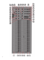
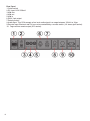
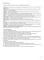
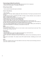
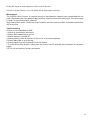
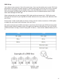
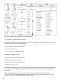
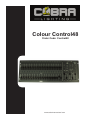
Colour Control48
Order Code: Control48
www.cobrainternational.com
User Manual
Cobra Colour Control 48
Dear Customer,
Thank you for purchasing the Cobra Colour Control 48. With decades of experience in design and
production, Cobra is one of the leading manufacturers of professional sound and lighting equipment.
This unit has been designed and manufactured to the highest of standards so you can be assured
you have made a good investment.
For optimum safety and to take full advantage of all the Cobra Control 48 features, please ensure
you read this manual in full.
Product Description:
The Cobra Colour Control 48 is a 48 channel DMX controller, suitable for use with dimmer packs,
LED lighting and effects lights. The controller is can store up to 96 scenes or chases with a total of
999 steps or scenes. This desk will work as a 24 channel double pre-set desk, or a 48 individual
channel desk.
Safety Advice:
1. Read this manual in full before operating this product.
2. Keep this manual in a safe place for future reference.
3. Carry and transport this product with care. Dropping this product may result in serious mechanical
failure.
4. The manufacturer accepts no responsibility for injury or damage caused by not following the
manual provided.
Protection from Electric Shock:
1. Do not connect the AC power plug to the unit before connecting your lights.
2. Only connect this unit to a mains socket with suitable trip and RCD protection.
3. To disconnect from the mains socket always remove by the mains plug. Do not attempt to remove
by pulling the mains cable.
4. Disconnect the unit from the mains supply before cleaning. Cleaning should be carried out with a
soft, dry cloth.
5. Do not expose this unit to any liquids.
6. Do not operate near exposed water or in high humidity.
7. Choose a suitable route for mains cables, ensuring trip hazards are avoided and the mains cable
is not at risk of being crushed.
8. Do not open this unit to service. There are no user serviceable parts inside. Any servicing or
repairs should be carried out by a qualified engineer only. Any user attempt to service or adapt this
unit will void your warranty and could result in serious malfunction or injury.
Protection from Fire:
1. Do not place near sources of heat or ignition.
2. Do not block any ventilation holes.
3. Check your AC wall socket will take the power you are applying to avoid overloading the mains
supply.
4. Ensure you are using the correct voltage DC power supply, set to the correct polarity.
2
Protection from Injury and Damage:
1. Do not attempt to modify this unit.
2. Always install the unit in a suitable location where vibrations to the unit are avoided.
3. Check this unit matches the mains voltage and frequency before plugging it in to your mains
socket.
4. If any liquids or objects have entered the unit, switch it off immediately and consult a qualified
engineer.
5. In the event of malfunction or damage to the mains cable, disconnect from the mains supply
immediately and consult a qualified engineer.
6. All parts should be replaced with genuine spare parts and carried out by a qualified engineer.
Contents & Unpacking:
1. The box should contain Cobra Colour Control 48, power supply and user manual.
2. If you suspect any damage or missing parts, please contact your dealer immediately.
Specifications:
Name: Colour Control 48
Code: Control 48
Power supply: DC 12v 500mA min.
Power consumption: 20 watts
Output: DMX 512 (3-pin)
Audio Input: 100mV ~ 1Vpp
Dimensions: 483 x 264 x 80mm
Weight: 4.3kg
Features
The Colour Control 12 is DMX 48-channel controller suitable for dimmer packs, LED lights and effect
lights.
Features Include
1. Controls up to 48 channels.
2. Scenes/chases can be stored.
3. Speed and fade can be used after programming.
4. Controller can be used in 24-channel double pre-set mode.
5. Chases and scenes can be mixed in playback.
6. A chase can have up to 999 steps.
7. 3-pin DMX output socket.
8. Audio input or built in mic, for playback of chases to the bass beat.
9. Midi control over some features.
Note: A knowledge of DMX is required to make full use of this controller and all of its features
The controller will automatically begin sending the FILE DUMP once the mode has been selected.
Therefore be sure that the other device has previously been set up to accept the transfer.
During FILE DUMP all other operations will cease to function.
If errors or power failure occurs, FILE DUMP will be interrupted and stop
.
3
Maintenance
The COBRA Colour Control 48 requires almost no maintenance. However you should keep the unit
clean. Disconnect the mains power supply and then wipe the cover with a dry cloth. Do not immerse
in liquid. Do not use alcohol or solvents.
Keep connections clean. Disconnect electric power and then wipe the DMX and audio
connections with a dry cloth.
Troubleshooting
If fixture is not responding to DMX:
1. Check all connections are correct.
2. Check DMX addressing is correct.
3. Check blackout is turned off.
4. Check polarity switch at the back of the unit is in the correct position.
5. Check fade slider is up to the top.
6. Check Master A is at the top and B is to the bottom.
7. If all the above doesn’t work, unplug from the mains, wait 30 seconds then plug back in.
8. If it is still not working, contact your dealer.
4
5
6
Controller Front
1. Pre-set A LED’s. Indicate which channels are on/off.
2. Channel sliders 1-24. These sliders will adjust the output of channels 1-24 from 0 to 100% or 0 to
255.
3. Flash buttons 1-48. These will activate the corresponding channel to maximum level when
pressed.
4. Pre-set B LED’s. Indicate which channels are on/off.
5. Scene LED’s. Indicate which stored scene/chase is active.
6. Channel faders 25-48. These sliders will adjust the output of the channels 25-48 when in 1-48
single pre-set, or adjust channels 1-24 when in double pre-set, or activate scenes/chases when in
chase/scene mode.
7. Flash button 25-48. These will activate the corresponding channel to maximum level and are also
used when saving scenes/chases.
8. Master A slider. Adjusts pre-set A (channels 1-24) overall intensity when in double pre-set mode
9. Blind button. When in scene/chase mode and when used in conjunction with a channel flash
button, this feature will remove a channel from a saved scene/chase.
10. Master B slider. Adjusts pre-set B (channels 1-24) when in double pre-set mode and is also the
master dimmer for stored scenes/chases.
11. Home button. Will deactivate the blind feature.
12. Fade slider. Adjusts fade time in manual mode or after scenes/chases have been stored.
13. Tap sync button. Tapping this button repeatedly will establish the chase speed.
14. Speed slider. Used to adjust the speed of the chase you are running.
15. Full on button. Momentarily brings all channels to full intensity.
16. Audio slider. Adjusts the audio sensitivity when the audio button is pressed and you are
playing back a chase.
17. Blackout button. Used to cancel out all output.
18. Step button. Used to manually go to the next step when playing back a chase and the speed
slider is set to show mode.
19. Audio button. Activates the audio sync when playing back a chase in chase/scene mode.
20. Hold button. Will hold a step when playing back a chase.
21. Park A and B buttons. In 1-48 single pre-set mode, park A will activate any active channel
sliders to their set output thus overriding master A slider. In double pre-set mode, Park A will override
Master A and Park B will override Master B. In chase/scene mode, park B can be used to play back
different scenes/chases at the same time (mix) or only 1 at a time (single).
22. Record exit button. Has two functions, one is to exit record mode when pressed with the
record button. The second is an add/kill feature. Pressed so the LED is on, if you then press a flash
button it will ‘0’ all outputs, other than the channel which corresponds to that flash button.
23. Record/shift button. Record is used to activate record mode, programme steps/scenes, or as
a shift button to alter other functions.
24. Page button. Tap to select pages of scenes/chases to be stored, or that have previously been
stored.
25. Mode select button. Used to select what mode you want to operate the desk in.
26. Dark button. Used to '0' all channel outputs.
27. Edit/All rev button. Will reverse the direction of a chase in playback mode. It is also used for
editing scenes/chases in programme mode.
28. Insert/% or 0-255.Used in conjunction with the shift button to display the output in either 0100% or 0-255. Is also used to insert scenes/steps in programme mode.
29. Delete/Rev one button. This button will reverse the chase direction when used in conjunction
with a flash button.
30. Up/chase rev button. Will reverse the direction of a chase when being played back. Is also
used in edit mode.
31. Down/beat rev button. Is used in edit mode.
32. Fog machine button. Used to control a fog machine with an IEC connection.
7
Rear Panel
1. On/off switch
2. DC input 12DC 500mA
3. Midi thru
4. Midi out
5. Midi in
6. DMX 3-pin output
7. Polarity switch
8. Audio input. This RCA accepts a line level audio signal in a range between 100mV to 1Vpp.
9. Remote input. Blackout and Full-on can be controlled by a remote switch (1/4 stereo jack socket).
10. Fog machine remote output (IEC socket).
8
Common Terms
The following are common terms used in intelligent light programming:
1. Blackout- is a state where by all lighting fixtures light output is set to '0' or 'off', usually on a
temporary basis.
2. DMX-512 - is an industry standard digital communication protocol, frequently used in
entertainment lighting equipment.
3. Fixture - refers to your lighting effect or other device such as a dimmer, which you can control.
4. Sliders - are also known as faders.
5. Scanner - refers to a lighting effect which has a pan and tilt mirror; However DMX controllers may
refer to this term when describing the control of a DMX512 compatible device.
6. MIDI - is a standard term for representing musical information in a digital format. A MIDI input
provides external triggering of scenes using MIDI devices such as a MIDI keyboard.
7. Stand Alone - refers to a fixtures ability to function independently of an external controller. This is
usually in sync to music due to a built in microphone.
8. Fader slider - is used to adjust the fade time between scenes within a chase.
9. Speed slider - affects the amount of time a scene will hold its state. It is also considered a wait
time.
10.Shutter - is a mechanical device in the lighting fixture that allows you to block the lights path. It is
often used to lessen the intensity of the light output or strobe.
11.Playbacks - can either be scenes or chases that are directly recalled by the user. A playback
may also be considered a program memory which can be used during a show.
12.Chase - is a program built up using steps/scenes.
13.Pack - normally refers to a dimmer pack which can come with different channel options. Some
have 4 outputs some have 12 for example.
First Time Operation
1. Remove all packaging materials.
2. Connect a DMX cable from controller to your first light or pack. Connect a DMX cable from the first
light or pack to the second. Do this until all lights or packs are connected.
3. Plug any par can/theatre spots in to your dimmer packs if you are using dimmer packs.
4. Plug your controller into the mains with the supplied AC/DC power supply.
5. Plug your dimmer packs or lights in to the mains.
6. If you are using 4-channel packs or 4-channel LED par cans, set the first unit to DMX address 1,
the second to DMX address 5, third to DMX address 9 and the fourth to DMX address 13. (some
lights/packs will have digital display, some will have small dip switches).
7. Once you have turned on your controller, check if the blackout light is illuminated. If it is, press the
black button.
8. Move the fade slider to the top.
9. Move Master A to the top and Master B to the bottom.
10. Using the mode select button put the controller into 1-48 single pre-set mode.
11. Move all the channel sliders up and your lights should have output. If they do not, switch the
polarity switch on the back of the controller.
12. Follow the rest of the manual to make full use of all the programming options.
9
Entering Program Mode (|Record Enable)
1. Whilst holding down the record button, press flash button #1-6-6-8 in sequence.
2. Release the record button. The record LED lights up.
Exiting Program Mode
1. Hold record/shift button then tap rec exit button.
Create a Scene/Chase
1. Record enable.
2. Select the 1-48 single mode by tapping the mode select button. This will give you control of all 48
channels.
3. Create desired output by adjusting the faders (changes in fixture attributes such as colours &
gobos, or simply dimmer values).
4. Press record to save the look into the temporary memory.
5. Repeat steps 2-4 until you have your desired chase.
6. Do not repeat steps 2-4 if you are only saving scene.
7. Select a scene master to store your scene. Tap the page button to select a page (1-4)
8. Press and hold the record button and tap the flash button for the scene that you wish to store to.
All LED’s will flash indicating the scene has been programmed in to memory.
9. You can continue programming in this way or exit. To exit program mode, press and hold the
record button and tap the rec exit button, the record LED will dim out.
Notes:
Deselect Blackout if LED is lit.
If you wish to create a static look, then you must create a scene composed by only one step. There
are 999 steps in total you can use.
Edit Enable
1. Record enable.
2. Use the page button to select the page that the program you wish to edit is on.
3. Tap the mode select buttons, to select chase/scenes.
4. Press and hold the edit button and tap the flash button (25-48) of the scene/chase you wish to
edit.
5. Release the edit button. The relevant scene LED should illuminate, indicating you are in edit
mode.
Notes:
This mode is displayed here only for the initiation of edit mode. Please see the following sections for
uses of this mode in more detail.
10
Delete a Step or Steps
1. Enter the edit mode
2. Tap the step button to scroll to the step you wish to delete.
3. Tap the delete/rev button when you reach the step you wish to delete. All the LED's will light,
indicating the deletion of the step.
4. Repeat steps 2&3 until all of the unwanted steps have been deleted.
5. Press and hold the record and rec exit button. The scene button LED will turn supress, indicating
that the edit mode has been exited.
Insert Step or Steps
1. Enter edit enable.
2. Using the step button, go to the position you wish to edit within a scene.
3. Using the mode select button put the unit into 1-48 mode.
4. Record a step.
5. Put the unit back to chase<>scene mode.
6. Press the insert button (your step has been added). You can check your scene has been added
by using the step button to go through the individual steps.
7. Exit edit mode.
Modify a Step or Steps
1. Enter the edit mode.
2. Tap the step button to scroll to the step which you wish to edit.
3. Whilst holding the up or down button, tap the flash button corresponding to the DMX channel of
the scene you wish to modify. Do this until you reach the desired intensity value read from the
display. You may then tap the flash button until you are satisfied with the new scene.
4. Repeat steps 2, 3 and 4 until all the steps have been modified.
5. Exit edit mode.
Notes:
Part of entering the edit mode is selecting which scene you wish to edit. See section on edit enable
for further instructions.
11
Erase a Scene/Chase
1. Record enable.
2. Select the page the desired scene/chase is on.
3. Press and hold record button.
4. Tap the flash button which corresponds to the scene/chase you wish to delete twice.
Erase all Scene/Chases
1. Record enable.
2. Hold record button and press flash 1,4,2,3 in sequence.
3. Release the record button, all LED's will flash indicating all programmes (scenes and chases)
have been deleted.
Record Clear
1. Record enable.
2. Record a scene with one or more steps.
3. If you are not satisfied with the scene, you may press and hold the record button and tap the rec
clear button. All LED's will flash, indicating the scenes have been cleared.
Notes:
All the scenes stored within the temporary memory of the controller will be erased by this process.
This will not affect the scenes already programmed onto a scene fader.
Faders 25-48 are used for the playing back of scenes/chases already recorded. This is only when
the recorder is in the chase <> scene mode. In this instance, Master Fader A will control the manual
fader controls, while the Master B will control the scenes being played back.
Playing a Scene/Chase
1. Press the mode select button to select chase <> scene mode.
2. Press the page button to select the correct page where the scene you wish to run is located.
3. Push the Master Fader B into its maximum position (fully down).
4. Move the desired channel fader (25-48) to its maximum, and the scene will fade in depending
upon current fade time.
5. Move the channel fader to adjust the output of the current program.
Notes:
The current mode is indicated by the 3 LED's:
Red is the Chase <> Scene mode
Yellow is 2-scene pre-set A/B mode
Green is 1-48 single mode
You may press and hold down the relevant flash button for the scene/chase to trigger momentarily
whilst working in scene/chase mode.
12
Playing a scene/chase by audio triggering
1. Select your scene/chase as described in the above section.
2. Press the audio button until its LED illuminates, indicating that audio mode is active.
3. Use the audio level fader to adjust the sensitivity.
4. To return to normal mode tap the audio button a second time, causing its LED to go out. Audio
mode is disengaged.
Notes:
This is the process for using the built-in microphone, or for using the audio input located on the rear
of the controller. This can be used for an alternative audio source for triggering the scenes/chases.
Fade time may also be used.
Playing a Scene/Chase Using The Speed Fader
1. Select a saved scene/chase.
2. Move the speed fader to the desired position (the top being the fastest).
3. Now you may move the speed fader to select your desired speed.
Notes:
Ensure audio mode is disengaged.
Fade time may also be used.
Change The Speed Mode Between 5 & 10 Minutes
1. Press & hold the record button.
2. Whilst holding down the record button, tap the flash button #5 or #10 three times.
3. The 5 min or 10 min LED should light, indicating the speed that the fader is set to run.
Midi in Mode
1. Press and hold the record button.
2. Press flash button 1, three times .
3. Release the record button.
4. The display shows 'CH-1' and the controller is in midi in mode.
5. Select the desired midi channel by pressing the respective flash button.
6. Hold down the record button and press record exit.
7. The midi channel has been memorized.
13
Midi out mode
1. Press and hold the record button.
2. Press flash button 2, three times.
3. Release the record button.
4. The display shows CH-0 and the controller is in midi out mode.
5. Select the desired midi channel by pressing the respective flash button.
6. Hold down the record button and press record exit.
Midi run
1. If midi data is not received within 10 minutes, the channel and programme turned on by midi will
turn off.
2. When sending/receiving a file dump, the device ID is 55H.
3. The different functions of individual notes are as follows.
Receive a Sys-ex Dump
1. Press and hold the record button.
2. Press the flash button 3 in pre-set A, three times.
3. Release the record button.
4. When the display shows IN, the controller is ready for receiving the dump.
When receiving the dump, all other functions are switched off. As soon as the transmission is
complete or cancelled due to errors, the controller returns to normal operation mode.
Send a Sys-Ex dump
1. Press and hold the record button.
2. Press the flash-button 4 in Pre-set A, three times.
3. Release the Record-button.
4. When the display shows OUT, the controller is ready for sending the dump.
When sending the dump, all other functions are switched off. As soon as the transmission is
complete or cancelled due to errors, the controller returns to normal operation mode.
Notes:
This is the process of copying your entire show to another colour controller. This will not work with
any other makes of device.
This process can take several minutes to complete.
The controller will automatically begin sending the file dump once the mode has been selected.
Therefore ensure that the other device has been set up to accept the transfer.
14
During file dump all other operations will cease to function.
If errors or power failures occur, file dump will be interrupted and stop.
Maintenance
The COBRA Colour Control 12 required almost no maintenance. However you should keep the unit
clean. Disconnect the main power supply and then wipe the cover with a dry cloth. Do not immerse
in liquid. Do not use alcohol or solvents.
Keep connections clean. Disconnect electric power and then wipe the DMX and audio connections
with a dry cloth.
Troubleshooting
If fixture is not responding to DMX
1. Check all connections are correct.
2. Check DMX addressing is correct.
3. Check blackout is turned off.
4. Check polarity switch at the back of the unit is in the correct position.
5. Check fade slider is up to the top.
6. Check Master A is at the top and B is at the bottom.
7. If all the above fails to work, unplug from the mains, wait 30 seconds then reconnect to the power
supply.
8. If it is still not working, contact your dealer.
15
DMX BASICS
DMX is short for digital multiplexer, which is a universal protocol designed for the lighting industry
allowing for controlling of intelligent fixtures like scanners, moving heads, LED par cans, dimmer
packs, fog machines etc.
DMX allows you to control many fixtures channels, normally up to 512 with varying channels from 0255 (0-100%).
This will give control of channels like gobo selection, up and down movements, colours and dimming
etc.
DMX is a very good system as all this information can be sent down one cable, used in conjunction
with a DMX controller with memory all your channel settings can be saved and recalled easily.
DMX was designed so that all manufacturers can use the same protocol/language to control their
fixtures allowing the end user to use any make of fixture on their DMX controller as long as both are
DMX compatible, and the controller has enough channels to control the fixture that is attached.
Fixtures have an input and output DMX socket, allowing you to connect from the controller to the
first fixture then from that fixture to the next (this is called daisy chaining).
Sockets are normally 3 pin XLR but can be 5 pin XLR as well.
DMX fixtures need to have a DMX address set, as this is so they can then decode the correct
information from the controller. This is normally done by a digital display panel, where the address
can be changed by simple up and down buttons; the address ranges from 1-512. In addition to this it
can be controlled by a row of small switches, called dip switches; there the required address is
converted to a binary number.
To work out your dip switch settings you can simply download a DMX calculator from the internet or
see our table further on.
The order in which fixtures are connected in a DMX line does not influence the DMX address, a
fixture set to DMX address 1 can be put in a DMX line from beginning, middle or end, as it is set to
address 1 it knows to take information from that point onwards.
16
DMX Wiring:
3 pin wiring is more common, 5 pin is the correct way. 3 pin may be used to save on cost. With 5 pin
connections, not all pins are used, though it is worth checking your manual for your fixture, as some
lights use the unused pins for low voltage control. 5 pin would be better so there is no confusion
over mixer leads and DMX leads in big rigs, sending a mixers 48v phantom power down a DMX
cable could damage the DMX light.
When making cables try and used proper DMX cable and do not connect pin 1 GND to the outer
casing of the connector as you might do with audio cables as this may cause erratic behaviour from
your fixture.
Do not make Y leads to split cables to fixtures; always use the in and out sockets or a DMX splitter
as again this may cause erratic behaviour from your fixture.
We recommend you to put a DMX terminator in any fixture which hasn’t got a DMX lead connected
from the output socket to another fixture; this again is to reduce erratic behaviour from your fixtures.
A DMX terminator is simply a male XLR plug with 120 ohms, ¼ watt resistor soldered across pin 2 &
3.
17
Each fixture takes up 5 DMX Channels (See Above)
The controller is a fairly basic 24 channel.
So you have a cable from the controller to the first fixture cable from first to second and so on, the
last light has a DMX terminator plugged in.
Fixture 1 would be set to DMX address:
1 dipswitch number 1 on.
Fixture 2 would be set to DMX address:
6 dipswitch numbers 2 & 3 on.
Fixture 3 would be set to DMX address:
11 dipswitch numbers 1, 2 & 4 on.
Fixture 4 would be set to DMX address:
16 dipswitch number 5 on.
We would recommend you to fully read manuals for your light and controller as some controllers tell
you what each fixture address needs to be, and some lights need other settings changed to make
them work.
18
When setting address you need to make sure fixtures don’t overlap from one to the next.
You can set 2 fixtures to the same address, and as long as they are the same fixture (i.e. same
channel layout) they will then do the same as each other.
19
DMX DIPSWITCH SET
0=OFF
1 = ON
X = OFF OR ON
1
2 3 4 5
0
0 0 0 0
1
0 0 0 0
0
1 0 0 0
1
1 0 0 0
0
0 1 0 0
1
0 1 0 0
0
1 1 0 0
1
1 1 0 0
0
0 0 1 0
1
0 0 1 0
0
1 0 1 0
1
1 0 1 0
0
0 1 1 0
1
0 1 1 0
0
1 1 1 0
1
1 1 1 0
0
0 0 0 1
1
0 0 0 1
0
1 0 0 1
1
1 0 0 1
0
0 1 0 1
1
0 1 0 1
0
1 1 0 1
1
1 1 0 1
0
0 0 1 1
1
0 0 1 1
0
1 0 1 1
1
1 0 1 1
0
0 1 1 1
1
0 1 1 1
0
1 1 1 1
1
1 1 1 1
9
8
7
6
0
0
1
0
64
65
66
67
68
69
70
71
72
73
74
75
76
77
78
79
80
81
82
83
84
85
86
87
88
89
90
91
92
93
94
95
0
0
0
1
32
33
34
35
36
37
38
39
40
41
42
43
44
45
46
47
48
49
50
51
52
53
54
55
56
57
58
59
60
61
62
63
0
0
0
0
1
2
3
4
5
6
7
8
9
10
11
12
13
14
15
16
17
18
19
20
21
22
23
24
25
26
27
28
29
30
31
96
97
98
99
100
101
102
103
104
105
106
107
108
109
110
111
112
113
114
115
116
117
118
119
120
121
122
123
124
125
126
127
0
0
1
1
128
129
130
131
132
133
134
135
136
137
138
139
140
141
142
143
144
145
146
147
148
149
150
151
152
153
154
155
156
157
158
159
0
1
0
0
160
161
162
163
164
165
166
167
168
169
170
171
172
173
174
175
176
177
178
179
180
181
182
183
184
185
186
187
188
189
190
191
0
1
0
1
192
193
194
195
196
197
198
199
200
201
202
203
204
205
206
207
208
209
210
211
212
213
214
215
216
217
218
219
220
221
222
223
0
1
1
0
224
225
226
227
228
229
230
231
232
233
234
235
236
237
238
239
240
241
242
243
244
245
246
247
248
249
250
251
252
253
254
255
0
1
1
1
256
257
258
259
260
261
262
263
264
265
266
267
268
269
270
271
272
273
274
275
276
277
278
279
280
281
282
283
284
285
286
287
1
0
0
0
288
289
290
291
292
293
294
295
296
297
298
299
300
301
302
303
304
305
306
307
308
309
310
311
312
313
314
315
316
317
318
319
1
0
0
1
TABLE SET DMX ADDRESS
320
321
322
323
324
325
326
327
328
329
330
331
332
333
334
335
336
337
338
339
340
341
342
343
344
345
346
347
348
349
350
351
1
0
1
0
352
353
354
355
356
357
358
359
360
361
362
363
364
365
366
367
368
369
370
371
372
373
374
375
376
377
378
379
380
381
382
383
1
0
1
1
384
385
386
387
388
389
390
391
392
393
394
395
396
397
398
399
400
401
402
403
404
405
406
407
408
409
410
411
412
413
414
415
1
1
0
0
416
417
418
419
420
421
422
423
424
425
426
427
428
429
430
431
432
433
434
435
436
437
438
439
440
441
442
443
444
445
446
447
1
1
0
1
448
449
450
451
452
453
454
455
456
457
458
459
460
461
462
463
464
465
466
467
468
469
470
471
472
473
474
475
476
477
478
479
1
1
1
0
480
481
482
483
484
485
486
487
488
489
490
491
492
493
494
495
496
497
498
499
500
501
502
503
504
505
506
507
508
509
510
511
1
1
1
1