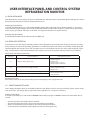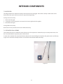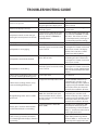
1
DCS REFRIGERATED DRAWERS
Service manual
Model
RF24D
1
TABLE OF CONTENTS
1.
2.
3.
4.
5.
6.
Introduction
1.1 Unit Specifications
3
1.2 Serial Nameplate
3
1.3 Before Servicing
3
1.4 Basic Refrigeration Tools
4
1.5 Installation
4
1.6 Electrical Requirements
4
Installation
2.1 Essential Requirements -Power5
2.2 Essential Requirements -Select Location5
2.3 Essential Requirements -Cabinet Clearance5
2.4 Essential Requirements -Stability
5
2.5 Essential Requirements -Before Placing Food in the Fresh Food Compartments
6
2.6 Electrical Connection
7
2.7 Grounding Method
7
2.8 Power Requirements
7
2.9 Select Location
8
2.10 Cabinet Clearance
8
2.11 Side Trim Installation
8
2.12 Installing Drawers
8
2.13 Anti-tip Installation - Floor Mount
9
2.14 Anti-tip Installation - Wall Mount
10
Sealed System
3.1 Introduction
11
3.2 Low Side Leaks
11
3.3 High Side Leaks
11
3.4 Restricted Capillary Tube
11
3.5 Access Valves
11
3.6 Evaporator Frost Pattern
12
3.7 Pressure and Temperature
12
3.8 Re-charging
13
Sealed System Components
4.1 Access to Mechanical Baseplate
14
4.2 Compressor
15
4.3 Condenser
17
4.4 Evaporator
18
System Components
5.1 Condenser Fan
19
5.2 Thermistors
20
User Interface and Control System Refrigeration Monitor
6.1 Introduction
22
6.2 Starting the Unit
22
6.3 Setting the Temperature Mode
22
6.4 Adjusting the Temperature Mode
22
6.5 Interior Light and Switch
22
6.6 Holiday Mode
23
6.7 Warning Alarms
23
6.8 Resetting the Alarms
23
6.9 Show Room Mode
24
6.10 Error Code Detection
24
6.11 Service Diagnostics Mode
24
1
TABLE OF CONTENTS
7. Interior Components
7.1 Lights
7.2 Drawers (for Refrigerated Drawers)
7.3 Glides (for Refrigerated Drawers)
7.4 Divider/Center Section (for Refrigerated Drawers)
7.5 Heater Strip (for Refrigerated Drawers)
7.6 Circulation Fan Assembly
8. Wiring Diagram
9. Ordering Parts
10. Troubleshooting Guide
12. Warranty
26
26
26
26
27
27
28
29
30
32
Introduction
1.1 Unit Specifications
Table A: Refrigerated Drawers Unit
Cabinet Dimensions (in)
Height
34
Width
29-7/8
Depth
24-1/4
Weight
(lbs)
195
Capacity
Gross
(cu. ft.)
5.8
Electrical
Requirements
120VAC/
60 Hz
3.3 Amp
Power
Cord
Length
(ft)
7
Compressor
Specifications
Piston
type
120Vac
60 Hz
Refrigerant
Charge
(oz)
3.6
Refrigerant
Type
134A
System
Refrigerant
Control
Temperature
Control
Condenser
Fan Motor
Evaporator Fan
Motor
UL
Capillary
tube
Electronic
Control with
LED display,
thermistor
input, and
Control
System
120 Vac
2.3 W
1300 RPM
12VDC
SA6813
1.2 Serial Nameplate
The serial nameplate is located inside of the unit on the upper left hand wall. The serial number will need to be
given when inquiring about the unit or ordering parts. See Figure 1.1 below for a sample serial tag with manufacturing date code logic.
SERIAL NUMBER:
20080313119R
2008
03
13
119
R
year
month
day
No. built that
day
Refrigeration
Figure 1.1
1.3 Before Servicing
••
Always disconnect power to any DCS product before attempting to service it. Always verify that power has
been disconnected.
••
If the unit has been running, use caution around the condenser, compressor, and copper tubing. These areas
may be very hot.
••
Use caution around the evaporator, condenser fins and baseplate edges. These areas are sharp.
••
Refrigerant is under high pressure. Always evacuate any system before attempting to open it.
••
Reasonable care and safe work methods should be practiced when working on any DCS product. Never work
with energized electrical equipment in wet or damp areas.
••
Use an appropriate work area and location when performing repairs. You will find that it is easier to repair
undercounter units if they are set on a raised platform or workbench.
••
Always wear protective safety glasses and gloves when working on any DCS product.
••
Any refrigerant, whether CFC, HCFC, or HFC (R-12, R-22, or R-134a), must be recovered. Federal regulations
prohibit the intentional venting or release of refrigerants during the service repair or disposal of an appliance.
3
Introduction
1.4 Basic Refrigeration Tools
The following list contains some of the tools required for basic refrigeration repairs:
1.
2.
3.
4.
5.
6.
7.
8.
9.
10.
11.
12.
13.
14.
15.
Hoses with R-134a couplers (must meet standards for handling R-134a refrigerant)
Approved and certified recovery system for R-134a
Manifold gage set for R-134a
Charging cylinder with R-134a
Weight scale (preferably in ounces to the nearest tenth of an ounce)
Access valves
Small and large tubing cutter
Brazing torch
Swaging tools
Multimeter
Leak detection equipment for detection of R-134a
Standard hand tools (assorted Phillips and standard screwdrivers, sockets, allen wrenches, adjustable wrenches, etc.)
Rivet gun and assorted rivets
Drill motor and assorted metal drills
Vacuum pump
1.5 Installation
•
•
Unit can be installed freestanding or built-in. The front of the unit must be unobstructed for proper air circulation
and operation at all times.
Unit must be on a LEVEL surface capable of supporting the loaded weight of the unit.
1.6 Electrical Requirements
WARNING
ELECTRICAL SHOCK HAZARD
Failure to follow these requirements could result in personal injury, electrical shock, or fire.
•
•
•
120 VAC, 60 Hz., single phase power is needed
Use an outlet with a 15 amp circuit. A ground fault circuit interrupter (GFI) electrical receptacle is to be used to supply
electrical power to the refrigerated drawer.
It is recommended that a single circuit receptacle be used for this unit only. DO NOT USE AN EXTENSION CORD.
4
INSTALLATION – ESSENTIAL REQUIREMENTS
2.1Power
••
The appliance must be installed so the power plug is accessible.
••
To ensure that the appliance is not accidentally switched off, connect your refrigerated drawer to its own power point. Do not plug in any other appliance at this power point or use extension cords, or double adapters, as the combined
weight of both power cords can pull the double adapter from a wall outlet socket.
••
For power requirements, refer to the information on the serial plate located at the upper left side, inner wall when the door is open.
••
It is essential that the appliance be properly grounded (earthed) with a three prong receptacle. Never cut or break off the grounding prong to fit a two-prong outlet.
2.2Select Location
••
The proper location will ensure peak performance of your appliance. Choose a location where the unit will be out of direct sunlight, away from heat sources and moisture.
••
Units with fan cooled condensers can be built into an under counter cabinet or freestanding.
••
Your refrigerated drawer should be operated in a properly ventilated area with ambient temperatures not to exceed below 40 degrees and above 100 degrees Fahrenheit.
••
Installation should be such that the unit can be moved for servicing if necessary.
2.3Cabinet Clearance
••
Ventilation is required from the bottom front section of the unit. Keep this area open and clear of any obstructions.
••
The adjacent cabinets and counter top can be built around the unit as long as no top trim or counter top is installed lower than the top of the upper drawer.
Figure 2.1 Leveling Leg
2.4Stability
••
It is important that all four corners of the refrigerated drawer base are supported firmly on a solid level surface to elimi
nate any cabinet movement.
••
Installing the appliance on a soft or uneven or unlevel floor may result in twisting of the cabinet and poor sealing of the doors. If the doors do not seal properly, warm air will enter the food storage areas causing the temperature to increase, resulting in food spoilage and food loss.
••
Position your refrigerated drawer. Turn front leveling legs clockwise (Fig. 2.1) to lower the front leveling leg. Raise the front of the appliance until it is stable and level.
••
The front leveling legs should take the majority of the weight of the cabinet and the cabinet should be stable, i.e. cabinet should not rock or wobble.
Warning
A free standing refrigerated drawer must have an anti-tip device installed for safety.
5
INSTALLATION – ESSENTIAL REQUIREMENTS
••
See anti- tip bracket installations (page 9 and 10).
2.5Before Placing Food in the Fresh Food Compartments
••
Remove all packaging. Ensure that all transit tape is removed from the refrigerated drawer.
••
Clean the inside of the appliance with warm water and a little liquid detergent to remove manufacturing and transportation dust.
••
Allow the refrigerated drawer to run empty for 2 - 3 hours to allow each compartment to cool to the appropriate temperature.
••
The appliance may have an odor on its initial operation, but this will go away when the refrigerated drawers have
cooled sufficiently.
6
INSTALLATION
HOW TO INSTALL YOUR OUTDOOR REFRIGERATED DRAWER
2.6Electrical connection
Check serial plate for correct power supply. Use only electrical power supply as specified on your appliance serial
nameplate. Do not use an extension cord!
WARNING!
Do not splash or spray water from a hose onto the refrigerated drawer!
Doing so may cause an electrical shock, which may result in severe injury or death.
2.7Grounding method
This product is factory equipped with a power supply cord that has a three-pronged grounded plug. It must be plugged
into a mating grounding type receptacle in accordance with the National Electrical Code and applicable local codes and
ordinances. If the circuit does not have a grounding type receptacle, it is the responsibility and obligation of the customer
to exchange the existing receptacle in accordance with the National Electrical Code and applicable local codes and
ordinances. The third ground prong should not, under any circumstances, be cut or removed. All UL listed refrigerated
products are equipped with this type of plug.
A ground fault circuit interrupter (GFI) electrical receptacle is to be used to supply electrical power to the refrigerated drawer
for outdoor applications. Contact an electrician if you need to install one to supply electrical power to your outdoor refrigerated drawer.
2.8Power requirements
24” Outdoor Refrigerated Drawer
••
120V 60Hz
••
1800 watt
••
3 wire outlet
••
15 amp circuit
Power Supply Cord
with 3-Prong
Grounding
Plug
AC Interface
Grounding Type
Wall Receptacle
NOTE: the plug show is for 120V units
Figure 2.2
Figure 2.3
7
INSTALLATION
HOW TO INSTALL YOUR OUTDOOR REFRIGERATED DRAWER
2.9Select Location
The proper location will ensure peak performance of your appliance. Choose a location where the unit will be out of direct
sunlight, away from heat sources and moisture. Units with fan cooled condensers can be built in. Unit should be operated
in a properly ventilated area with ambient temperatures above 40 degrees and below 100 degrees Fahrenheit.
Installation should be such that the cabinet can be moved for servicing if necessary.
2.10Cabinet Clearance:
••
Ventilation is required from the bottom front section of the unit. Keep this area open and clear of any obstructions.
••
The adjacent cabinets and counter top can be built around the unit as long as no top trim or counter top is installed
lower than the top of the upper drawer. See Fig. 2.5.
2.11 Side Trim Installation
Prior to installation, align trim with the refrigerated drawer height and mark the screw hole locations. Attach side trim to
the inner side of the cabinet so that the trim faces outward (away from the appliance’s door) and fasten with appropriate
screws suitable for the type of cabinet material (Fig. 2.6).
2.12Installing Drawers
••
Place the unit in front of the counter opening. Make sure that the floor is protected when sliding the drawer unit into
place.
••
Determine the minimum height of the counter top opening (Fig. 2.5).
••
Lower the front and rear leveling legs (Fig. 2.5) so the top of the drawer cabinet is 1/8” lower in the back of the
cabinet and 1/2” lower in the front of the cabinet than the counter top opening.
••
Make the electrical connection by plugging the unit into the power outlet and locating the power cord so it will not be
damaged when the refrigerated drawer is installed.
••
Slide the refrigerated drawer into cabinet location and adjust the front legs until the unit is level and there is the same
amount of load on each leg.
24” Outdoor Refrigerated Drawers
Dimensions
Island Preparation
Side Trim Installation
15-1/8
Mounting
screw not
provided
15-1/8
3-1/2”
Figure 2.4
24-1/8
Figure 2.5
8
Figure 2.6
INSTALLATION
ANTI-TIP INSTALLATION INSTRUCTIONS
A free standing refrigerated drawer must have an anti-tip device installed as per these instructions. If the drawer is removed
from its location for any reason, make sure that the device is properly engaged when you push the drawer back into the
original location. If device is not properly engaged, there is a risk of the drawer tipping over, causing property or personal
injury if you or a child stand, sit, or lean on an open drawer.
WARNING
2.13Floor Mount Installation:
The anti-tip bracket can be located on the floor in the left or right rear corner
of the refrigerated drawer.
• ALL DRAWERS CAN TIP
Step by step instructions for locating the position of the bracket:
• INSTALL ANTI-TIP
BRACKET PACKED
WITH UNIT
• INJURY COULD RESULT
1. Decide where you want to place the Drawer. Make a temporary line on
the floor in line with the drawer face, “A” as shown in Figure 06.
• SEE INSTRUCTIONS
2. At the center point where the drawer will be, draw a center line “B”
(Fig. 2.7) perpendicular to line “A” to the rear of the unit. Make a mark
on line “B “ 24-1/2 inches from line “A”.
BOTTOM VIEW OF DRAWER
3. Then make another perpendicular line “C”at this mark.
Make a mark on line “C” 11-1/2 inches from line “B”
either right or left.
23-7/8”
Anti-tip
Bracket
4. At this mark, drill 1/8” diameter pilot hole in the floor.
Center line
11-1/2”
5. Fasten the bracket to the floor thru the slotted hole (see
Fig. 2.8) using the appropriate fasteners for the type of
floor.
6. Position the unit so that the leveling leg engages into the
anti-tip bracket (Fig. 2.8).
Refrigerated
Drawer
7. Check for proper installation of the drawer and anti-tip
device by grasping the back of the unit and carefully
attempting to tilt the drawer forward.
24-1/2”
24”
B
A
Front
Figure 2.7
Leveling Leg
Slotted hole
for floor
installation
11-1/2”
C
Open slot
ER
NT
CE
Figure 2.8
9
E
LIN
B
PER
PEN
DIC
ULA
RL
INE
INSTALLATION
ANTI-TIP INSTALLATION INSTRUCTIONS
2.14WALL MOUNT
To Drawer
Refrigerator
1. Remove the bracket from its original shipping position on the back of the
unit (Fig. 2.9 and 2.10).
2. Reattach the bracket to the back of the unit using the existing screws from
the unit’s back panel (Fig 2.11).
3. Push the unit against the wall so the bracket is flush with the wall
adjacent to the back panel.
4. Using a pencil and the bracket as a template, trace the bracket on the
wall, making sure 2 of the screw holes are aligned with a stud in the
wall.
To wall
Figure 2.9
5. Pull the unit away from the wall.
6. Remove the screws that connect the upper and lower sections of the
Anti-Tip Bracket. Mount the lower section of the bracket that is not
attached to the unit to the wall where you had marked and drilled pilot
holes in the wall/wall stud for mounting. Attach the lower bracket to
wall.
7. Push the unit back against the wall and align the upper section with
the lower section of the Anti-Tip Bracket such that you can refasten the
original screws that secure the upper and lower sections of the Anti-Tip
Bracket (Fig. 2.12). Your installation is now complete.
Figure 2.10
Adjacent wall
Drawer Refrigerator
Side View
Figure 2.12
Figure 2.11
10
Sealed System
3.1 Introduction
The following should always be practiced with any sealed system that has been opened. ONLY OPEN THE SEALED
SYSTEM AS A LAST RESORT AND AS A FINAL DIAGNOSIS. Always check other areas of operation such as wiring, airflow,
thermostat, etc. before opening up the sealed system. Many times these areas can resemble sealed system problems.
The diagnosis of a sealed system can be determined by accurate pressure and temperature measurements. Also, checking the evaporator frost pattern is a great way to tell if a charge is adequate within a system.
1. Use a leak detection system that will detect R-134a refrigerant. Leaks need to be found on any leaking system BEFORE the repair takes place.
2. The drier must be replaced anytime the sealed system is opened. Always use a DCS drier. Failure to do so may cause
repeated system failure in the future.
3. Limit time the system is opened. DO NOT EXPOSE THE OPEN SYSTEM FOR MORE THAN 15 MINUTES. This will result
in sealed system failure. Leave replacement parts sealed and/or pressurized until ready to install.
4. The compressor must be replaced if there is a low side leak. Moisture has been drawn into the system if the unit has
been running for an extended period of time. Be sure to flush the system with dry nitrogen gas and evacuate to 50
microns before re-charging (see Section 2.2, Low Side Leaks).
5. A new evaporator assembly must be ordered if the capillary tube is found to be plugged or severely restricted. Restrictions cannot be flushed out.
6. Be sure to purge the system with dry nitrogen gas after final brazing. This will flush out any air or moisture that may
have entered the system before being absorbed into the ester oil.
3.2 Low Side leaks
Low side leaks consist of a break in the system at the evaporator, low side (suction) return line, or accumulator. If a leak is
found in any of these areas, moisture has probably entered the system. The compressor and drier will have to be replaced
and the system will need to be flushed thoroughly with nitrogen gas and evacuated to 50 microns before re-charging.
3.3 High Side Leaks
High side leaks consist of a break in the system at the condenser, high side tubing, drier, or capillary tube. If a leak is
found in any of these areas, the drier must be replaced and the system can be flushed with nitrogen gas, evacuated to 50
microns, and re-charged.
3.4 Restricted Capillary Tube
Moisture or other contaminants that enter the system can cause deposits in the system. These deposits will usually collect in the capillary tube and form a restriction that cannot be completely removed by flushing. If the capillary tube is
found to be restricted, the evaporator, compressor, condenser, and drier should all be replaced.
3.5 Access Valves
A temporary access valve can be used to service or evaluate the system. From these access valves, you can evacuate,
charge, and recover the system. The access valve can be installed on the compressor’s process tube (this will also be a
low pressure side). Be sure to cap off access valve while servicing. This will prevent contamination of the system and/or
refrigerant from leaking. After servicing, the access valve should be removed. A pinch-off tool can be used to close the
system to remove the access valve and then braze the hole for the access valve to seal the system. Be sure to leak check
after brazing.
11
Sealed System
3.6 Evaporator Frost Pattern
Checking the evaporator frost pattern is a good way to quickly diagnose simple sealed system problems. This can
be done by allowing the unit to run (at least 10 minutes) with the door open for at least 5 minutes. This will help
speed up the normal frosting of the evaporator plate. By visually inspecting the evaporator and feeling it with your
hands, you will see and feel frost across the plate. It is absolutely necessary for the frost to cover the entire evaporator plate. This will ensure the system has been charged to its specified amount or does not have a leak. A partial
frost pattern may lead to excessive run times or even 100% run mode. This is because the frost does not reach the
area of the evaporator thermistor thus it does not sense the temperature required to cycle the unit off.
3.7 Pressure and Temperature
There are a couple of ways to measure temperature of the evaporator plate:
1. Use a thermocouple to measure the temperature of the evaporator plate. The thermocouple must be secured to the
evaporator when taking the measurement.
2. If it has been determined that there is proper contact between the thermistor and evaporator plate, the thermistor
resistance value can be corresponded to the temperature (see Table C in Section 5.2, Thermistors for values).
NOTE: The temperature and pressure reading must be taken while the unit is on and running. Use gage pressure readings from the compressor’s process tube (low side) access valve.
Table B: Refrigeration Temperature-Pressure Chart for R-134a
Degrees F
Pressure (psi) R-134a
Degrees F
Pressure (psi) R-134a
-12
1.1
36
31.3
-8
2.8
38
33.2
-4
4.5
40
35.1
0
6.5
42
37.0
2
7.5
44
39.1
4
8.5
46
41.1
6
9.6
48
43.3
8
10.8
50
45.5
10
12.0
52
47.7
12
13.1
56
52.3
14
14.4
60
57.5
16
15.7
64
62.7
18
17.0
68
68.3
20
18.4
72
74.2
22
19.9
76
80.3
24
21.4
80
86.8
26
22.9
84
93.6
28
24.5
88
100.7
30
26.1
92
108.2
32
27.8
96
116.1
34
29.5
100
124.3
Pressure will vary depending upon the ambient temperature and current stage of operation for the unit. For example,
the unit will have pressure between 0 and 5 psi just before entering the off cycle. Normal running pressures on the low
side will average 5 to 10 PSI.
12
Sealed System
If low side pressure is below pressure in Table B, check for the following:
1. A system leak
2. Capillary tube or evaporator is restricted
3. Insufficient compressor (does not pump properly)
If low side pressure is above pressure in Table B, check for the following:
1.
2.
3.
4.
5.
Restricted air flow
Dirty condenser coil
Overcharged system
Low side leak
Inefficient compressor
3.8 Re-charging
Re-charging of the unit should be done only after diagnosing and repairing the system. Be sure to flush the system with dry nitrogen gas and evacuate to 50 microns before re-charging.
The method for re-charging the unit is by weight using vapor refrigerant. Using manifold gage set-up, hook up charge hoses to
the access valve on the compressor’s process tube. If any access valve is attached to the high side process tube, remove it and
then seal the tube by brazing before charging. Charge the unit to specified amount (see Section 1.1, Unit Specifications for charge
specifications per model).
After re-charging the system, check pressures and refer to Table B for corresponding temperatures and pressures. If pressures are
incorrect, check the sealed system, recover the charge, repair, evacuate, and then re-charge.
It is normal to have some condensation or slight frost on the suction line. Typically this will occur towards the end of a run cycle. If
the frost continues down the suction line to the compressor, the system is overcharged. It is important that the insulation remains on the suction line and the capillary tube together after any repair and that it is sealed on both ends. Be sure to replace the
refrigeration putty in the hole of the foam where the refrigerant lines go through the back of the unit. Spread the putty out evenly
filling in the cracks to prevent air from leaking in and out.
13
Sealed System COMPONENTS
4.1 Gaining Access to Mechanical Baseplate
The mechanical baseplate is located in the rear of the unit. Most major mechanical and electrical components on the
unit mount directly to the baseplate. This creates easy access for servicing of the sealed system and mechanical/electrical components. To gain access to the mechanical baseplate, remove the screws that hold the lower shroud in place
and then remove the shroud (see Figure 4.1). To facilitate working on any component mounted to the mechanical base,
remove the screws that hold the baseplate to the chair frame and slide out the baseplate enough to allow working room
required (see Figures 4.2 and 4.3).
Remove screws.
Remove screws securing
the mechanical baseplate.
Figure 4.2
Figure 4.1
Slide out the mechanical
baseplate.
Figure 4.3
14
Sealed System
4.2 Compressor
The compressor is the heart of the refrigeration system (see Figure 4.4). However, it relies on other parts of the system to function.
Make certain that the other parts of the system are functioning correctly before determining that the compressor is faulty.
Compressor
Drier
Figure 4.4
The following should be observed before concluding the compressor is faulty:
1. Low high side pressures, warm evaporator plate, cool condenser coil, or little or very low current draw from the unit will indicate a faulty compressor.
2. Check for continuity between the compressor terminals and the shell of the compressor. If continuity is found, the compressor is faulty and will need to be replaced.
3. Check for resistance between all compressor terminals. The resistance will vary from terminal to terminal and from compressor to compressor due to age and use. If no resistance is found, the compressor is faulty and will need to be replaced.
Removing the Compressor:
1. Disconnect power to the unit.
2. Remove the back panel and lower shroud (see Figure 4.1).
3. Remove the screws that hold the baseplate to the chair frame of the unit and slide out the mechanical baseplate (see Figures
4.2 and 4.3).
4. Install sealed system access valve(s) and recover refrigerant. After recovering, be sure to cap off the access valve(s) to prevent
contamination of the system.
5. Remove the cap from the rear of the compressor to expose the starter and overload (see Figures 4.5 and 4.6).
6. Disconnect the PTC starter and overload from the compressor by pulling off. Disconnect the wires from the starter and overload.
7. Un-braze and remove capillary tube from drier assembly (see Figure 4.4).
8. Un-braze and remove suction line at compressor (see Figure 4.7).
9. Un-braze high side line from the compressor going to the condenser (see Figure 4.7).
10. Remove compressor by removing the three lock nuts on the mounting plate of the compressor (see Figure 4.7). Lift the compressor off of the carriage bolts.
15
Sealed System
Installing the Compressor:
1. Install the four rubber grommets in the bottom of the new compressor and install the three sleeves where the carriage bolts
will be located. Mount the new compressor and install the three washers and lock nuts and tighten to 45 in-lbs. DO NOT
REMOVE THE RUBBER PLUGS AT THE TUBE STUBS ON THE COMPRESSOR AT THIS TIME.
2. Install and braze new drier assembly to condenser. Then install and braze capillary tube to drier. Remove the plug for the
high side line to condenser. Install and braze the line to the compressor.
3. Remove the plug for the process tube on the compressor. Install and braze process tube. Be sure to cap off end to prevent
any contamination.
4. Remove the plug for the suction line on the compressor. Install and braze the suction line from the evaporator. BE SURE TO
ALSO REINSTALL THE SUCTION LINE AND TUBING HARNESS INSULATION TUBES.
5. Reinstall the PTC starter and overload and wire according to the wiring diagram (see page 28, Wiring).
6. Reinstall the compressor cap.
7. Reinstall the screws that secure the baseplate to the chair frame of the unit. Be sure to fasten down the ground wire to the
baseplate.
8. Charge the unit (see Section 3.8, Re-charging).
9. Reinstall back panel and lower shroud to complete installation.
Figure 4.5
Figure 4.6
Suction line tubing going to the
evaporator.
Process tube
High side tubing going to the
condenser.
Compressor lock-nut
Figure 4.7
16
Sealed System
4.3 Condenser
The condenser is a steel tube serpentine with copper alloy fins that removes heat from hot, high pressure vapor from the compressor (see Figure 4.8). The most common trouble is lack of airflow from either a restricted intake or exhaust opening in the front
of the unit. Lint, dust, hair, and dirt build-up needs to be removed from the condenser periodically to allow the unit to perform
properly.
Figure 4.8
It is possible that the condenser might need replaced because of an unrepairable leak or a restriction that cannot be flushed out.
System high side pressures and temperatures will verify if this is the case.
Removing the Condenser:
1. Disconnect power to the unit.
2. Remove back panel and lower shroud (see Figure 4.1).
3. Remove the screws that hold the baseplate to the chair frame of the unit and slide out the mechanical baseplate (see Figures
4.2 and 4.3).
4. Install sealed system access valve(s) and recover refrigerant. After recovering, be sure to cap off the access valve(s) to prevent
contamination of the system.
5. Remove the condenser fan by removing the four screws on the fan mounting bracket at the baseplate. The fan wire leads can
be left connected. Set the fan assembly to the side out of the mechanical.
6. Remove the condenser fan shroud.
7. Un-braze capillary tube from drier assembly.
8. Un-braze high side tubing from the compressor.
9. Remove the condenser and drier assembly.
Installing the Condenser:
Reverse the removal procedure for installation (see above). Always install a new drier after opening the sealed system. Be sure to
flush the system and evacuate to 50 microns before weight charging. If contamination was found or determined, the evaporator
should also be replaced at this time.
17
Sealed System
4.4 Evaporator
The evaporator uses evaporating refrigerant to remove heat from the inside of the unit ultimately making the interior cold. The
shape and size of the evaporator may vary among the models covered by this service manual but the fundamentals are the same
(see Figures 4.9). The RF24D uses a vertical right angle evaporator plate.
It is normal for the evaporator to frost up during its run cycle. This frost will dissipate once the unit reaches its “cut out” temperature and the compressor and fan stop. This condensate water will flow to the rear of the machine in a condensate pan where it will
be evaporated from compressor and fan heat. It is very important that the evaporator frosts in a uniform pattern across the plate
(see Section 3.6, Evaporator Frost Pattern). A partial frost pattern can lead to excessive run times and cooling issues.
Figure 4.9:
Evaporator plate used in the RF24D
18
System COMPONENTS
5.1 Condenser Fan
The condenser fan is used to force air over the condenser coil. The fan will cycle on and off with the compressor which means
that when the compressor is running so is the fan and when the compressor is not running neither is the fan (see Figure 5.1).
Figure 5.1
To check the condenser fan:
•
•
•
•
Make sure the motor shaft turns freely. This can be done by rotating the fan blade by hand and observing any excessive resistance.
Check for resistance between terminals. If no resistance is found, replace the condenser fan.
Check for continuity between terminals and fan casing. If continuity is found, replace the condenser fan.
Check current draw. Typical current draw will be 0.15 amp without fan resistance. If current draw is 0.19 amp or more, check
for resistance in air movement or objects touching the fan blade. If this is not found, replace the condenser fan.
Removing the Condenser Fan:
1. Disconnect power to the unit.
2. Remove access panel and rear panel.
3. Remove the grill by removing the screws and disconnecting the wires to the rocker switch. Be sure to mark where these wires
go for reassembly.
4. Take out the screws that secure the top of the electrical bracket located in the front of the mechanical area.
5. Remove the screws that secure the baseplate to the cabinet on the bottom of the unit.
6. Gently slide the mechanical out the back of the unit to gain access to the condenser fan.
7. Disconnect the neutral white wire lead (black ribbed wire) and hot wire lead (black smooth wire) from the wire harness.
8. Remove the condenser fan.
Installing the Condenser Fan:
Reverse the removal procedure for installation (see above).
19
System COMPONENTS
5.2 Thermistors
The refrigerated drawers utilize two thermistors: one is known as the evaporator thermistor and the other as the display thermistor. Each thermistor has a different function for input to the electronic control.
Evaporator thermistor:
The evaporator thermistor turns the unit on and off. It is secured to the evaporator or cabinet liner.
Display thermistor:
The display thermistor is connected to the LED display and displays the temperature inside the unit on the display panel.
The following will happen in the event of one or both thermistors fail:
1. If the evaporator thermistor fails, all loads will be shut off and the unit will not run.
2. If the evaporator thermistor senses temperature outside of 0-140 degrees F, all loads will be shut off and the unit will not run.
3. The display panel will flash E3 for an evaporator thermistor failure and E4 for a display thermistor failure. If both thermistors
fail, the error codes will be displayed sequentially. An audible alarm will also sound six times every minute if either one or
both thermistors fails.
The thermistor can be checked by use of a multimeter with the ability to read resistance. To check the thermistor:
1. Disconnect and remove thermistor from unit.
2. Use a reference temperature point that is know (such as an ice bath) and measure the resistance across the wire leads.
3. Compare the recorded resistance with Table C.
If measured resistance falls outside the resistance given in Table C within 4% of the value, the thermistor is bad and will need to be
replaced.
Table C: Resistance versus Temperature Chart
Temperature (C)
Temperature (F)
Resistance (K-OHMS)
-15
5
11.350
-10
14
8.918
-5
23
6.700
0
32
5.630
5
41
4.520
10
50
3.652
15
59
2.970
20
68
2.430
25
77
2.000
If the thermistor has been tested and is found to be good, check the temperature of the evaporator plate and the resistance of the
thermistor. If the temperature of the evaporator plate does not correspond to a proper resistance from the thermistor, check for a
proper and secure connection of the thermistor to the evaporator plate bracket.
20
System COMPONENTS
Removing the Evaporator Thermistor:
1.
2.
3.
4.
5.
Disconnect power.
Remove back panel and lower shroud.
Disconnect the evaporator thermistor connector at the electronic controller.
Remove evaporator thermistor by removing the screw securing it.
Feed the thermistor wire out through the opening in the back of the unit.
Installing the Evaporator Thermistor:
Reverse the removal procedure for installation (see above).
21
User Interface Panel and Control System
Refrigeration Monitor
ON
SET
WARMER
COOLER
OFF
FAULT
F/C
Power Failure +/ Temp Alarms Off Press ON/OFF to Reset
PRESS and HOLD
Figure 6.1
6.1 Introduction
DCS’s control system refrigeration monitor governs the intuitive user interface panel. The control system informs you if the unit is
not working properly through both visual and audible alerts. The LED display panel displays a steady green light when the control
system is enabled. See Figures 6.1 above for example user interfaces.
6.2 Starting the Unit
To start the unit, push and hold for five seconds the “ON/OFF” button located on the display panel. Upon turning the unit on, the
display will read the actual temperature inside of the unit. If the interior temperature is greater than 99 degrees F, the display will
flash 99 until the temperature drops to 99 degrees F.
6.3 Setting the Temperature Mode
The unit can display either Fahrenheit (F) or Celsius (C). To do so, press the “F/C” button on the display panel.
6.4 Adjusting the Temperature Control
The setpoint out of the factory is approximately 55 degrees F. The temperature control is adjustable from the low 30s to the high
40s in the refrigerated drawers. The setpoint out of the factory is approximately 38 degrees F. The range or refrigerated drawers,
allows flexibility of temperature preferences and provides the ideal food storing temperatures. The temperature can be lowered
or raised by first pressing the “SET” button on the display panel. A “SET” icon will be displayed. This icon will turn off 10 seconds
after completing the adjustments. Pressing either the “WARMER” or “COOLER” buttons will raise or lower the set temperature by
one (1) degree F or C (depending on the setting). NOTE: As with any refrigeration product, there is a slight temperature variance
at different locations within the cabinet.
6.5 Interior Light and Switch
For Refrigerated Drawers:
The light switch will automatically turn on the light when the drawer(s) is opened and off when the drawer(s) is closed. There are
two light switches in each drawer unit: one on the top and one on the bottom. They are both located on the inside left hand of
the drawers. In addition to turning the light on and off, the light switches also turn the display panel and interior fan(s) on and off.
22
User Interface Panel and Control System
Refrigeration Monitor
6.6 Holiday Mode
The unit is equipped with a Holiday Mode of operation. When Holiday Mode is enabled, the displays, audible alarms, lights, and all
options are disabled. The user interface buttons remain enabled with audible key tones disabled.
Enabling Holiday Mode:
Press and hold the “SET” button while pressing the “F/C” button four (4) times within seven (7) seconds. The display will flash “SA”
seven (7) times and then the unit will enter Holiday Mode.
Disabling Holiday Mode:
Press and hold the “SET” button while pressing the “F/C” button four (4) times within seven (7) seconds.
•
•
•
Holiday Mode automatically disables after 72 hours.
A power outage will not disable Holiday Mode. Disabling can only be accomplished by the automatic time-out or by the user.
The display returns to operation prior to Holiday Mode activation.
6.7 Warning Alarms
The Control System refrigeration monitor will inform you if the unit is not functioning properly. It provides both visual and audible
alerts if the temperature rises above or falls below the set temperature, if there is a power failure, or if the door is left ajar.
•
•
•
Door Ajar: If the door is left open for more than five (5) minutes, an audible alarm will sound three (3) times every 30 seconds
and the LED light will flash green. This will stop as soon as the door is closed.
High and Low Temperature: If the unit reaches a temperature either above or below the set point temperature for more than
one (1) hour, an audible alarm will sound six (6) times every minute and the LED will flash red. This will continue until the
alarm is reset. The alarm may occur when changing set-points in excess of 10 degrees F and/or high usage which is normal.
Power Failure: If the unit experiences a power failure, the LED will flash amber. This will continue until the alarm is reset. With
a power failure, no audible signal is heard. The alarm may occur upon initial installation which is normal since the unit was
run at the factory to verify quality.
6.8 Resetting the Alarms
Close door to reset Door Ajar alarm. Press the “ON/OFF” button for approximately one (1) second to reset all other audible and
display alarms.
NOTE: Although pressing the “ON/OFF” button will reset the alarms, the alarm will resume if the “alarm condition” still exists.
23
User Interface Panel and Control SysteM
Refrigeration Monitor
6.9 Show Room Mode
Show Room Mode is used mainly by salespersons and distributors. When the unit is in Show Room Mode, it will operate as if functioning normally; however, the internal components will not run.
Enabling Show Room Mode:
To enable Show Room Mode, press and hold the “ON/OFF” button while performing a “Power On Reset” (POR), i.e. - disconnect
and reconnect the power supply to the unit. When Show Room Mode is enabled, the compressor, condenser fan, internal fan(s),
heater, reverse gas solenoid, and alarms are disabled. The display will show the last set point entered.
Disabling Show Room Mode:
To exit Show Room Mode, initiate a “Power On Reset” (POR) only.
6.10 Error Code Detection
The microprocessor in the control continually monitors critical refrigeration system components for proper operation. If component parameters exceed normal operating specifications, an audible alarm will sound six times every minute and the display will
automatically flash the respective error code. If multiple errors are noted with the unit, the error codes will be displayed sequentially. See Table D: Error Code Detection Reference for respective error codes descriptions and the potential causes of failure.
Table D: Error Code Detection Reference
Error Code
Error Code Reference
Potential Causes of Failure
E1
Compressor fault (high/low amps)
1. Compressor wires disconnected.
2. Faulty compressor.
3. Faulty control.
4. Faulty compressor overload.
5. Faulty compressor PTC starter.
E2
Condenser fan motor fault (high/low amps)
1. Condenser fan motor wires disconnected.
2. Faulty condenser fan motor.
3. Faulty control.
E3
Evaporator thermistor “sensor B” fault (out-of-range)
E4
Display thermistor “sensor A” fault (out-of-range)
1. Disconnected wire causing open.
2. Shorted thermistor wires.
3. Faulty thermistor.
Resetting Error Codes:
Error Codes can only be reset by disconnecting and reconnecting the power supply to the unit.
6.11 Service Diagnostics Mode
Service Diagnostics Mode allows you to identify the firmware and software versions, test status of “model specific” system components and sensors, and change state of components where applicable (i.e. - compressor on/off, etc...).
Enabling Service Mode:
To enable Service Mode, press and hold the “WARMER” button while pressing the “COLDER” button four (4) times within five (5)
seconds.
•
•
•
•
You cannot enable Service Mode while in Set Mode.
All system functions will remain in their current state while in Service Mode.
Alarms are disabled during Service Mode and reset after exiting Service Mode.
Service Mode will automatically disable after five (5) minutes of no keypad entry.
24
User Interface Panel and Control System
Refrigeration Monitor
After entering Service Mode, the first number that you will see indicates the software model number for the particular unit you are
servicing.
Model
Description
Software Model Number
RF242D
24 inch Refrigerated Drawers
17
The second number you will see indicates the software version release. For example, if you see 39 on the display panel it indicates
software version 3.9 and 41 indicates software version 4.1.
Diagnostics:
While in Service Mode, press the “SET” button to step through Tests 0-9. The first digit of the display will show the test number.
The second digit indicates the current state of each component under test and is displayed as “1” being ON, CLOSED, or SHORTED
and “0” being OFF or OPEN. Tests 0 and 1 reveal an open or shorted condition detected at the sensor inputs. Tests 2 through 6
allow you to turn loads ON with the “WARMER” button and OFF with the “COLDER” button. Tests 7 through 9 verify state change
of the door switches and/or magnetic reed sensor. The component tests available are described in Table F: Available Component
Tests.
Table F: Available Component Tests
Test #
Component Description
0
Temp Sensor A - Evaporator
1
2
Available Status Indicators
OK
Off/Open
On/Shorted
0-
00
01
Temp Sensor B - Display
1-
10
11
Compressor
n/a
20
21
3
Interior/Ice Maker Fan
n/a
30
31
4
Reverse Gas Solenoid
n/a
40
41
5
Condenser Fan
n/a
50
51
6
Mullion Heater
n/a
60
61
7
Door A Sense
n/a
70
71
8
Door B Sense
n/a
80
81
9
Door C Sense
n/a
90
91
Note: Must use magnet to change state of Door C Sense
Disabling Service Mode:
To exit service mode, press and hold the “WARMER” button while pressing the ”COLDER” button four times within five seconds.
•
Service Mode will automatically disable after five minutes of no keypad entry.
25
Interior Components
7.1 Lights
For Refrigerated Drawers:
The refrigerated drawers are equipped with two lights: one on the inside top of the drawer and one in the divider.
Replacing the Top Light:
1.
2.
3.
4.
5.
6.
Loosen the screws to the control housing. You do not need to remove them.
Pull the control housing forward out of the screw slots.
Look inside the control housing and remove the wire connector to the light.
Press down and out on the LED bulb and lens. You will need to press the release tab on the lens.
Remove old bulb and set aside.
Insert new bulb and reverse steps 1-4 to complete.
Replacing the Divider Light:
1. Remove screws to the divider section and pull the divider out from the unit.
2. Flip the divider over for easier access to the lens assembly. Be careful not to disturb other wiring inside the unit.
3. Press in on the lens release tabs while simultaneously prying the lens upward using a flat-blade screwdriver. The release tabs
are located at the midpoint of the front and rear edge of the lens.
4. Unhook lens from wire connector and remove it from the divider. Disgard the lens.
5. Attach wire connector to new lens and snap lens back into place.
6. Reattach divider section to the unit.
7.2 Drawers (for Refrigerated Drawers)
Each drawer unit is equipped with two drawers: a top and a bottom. If necessary, the drawer fronts can be adjusted.
Adjusting the Drawer Fronts:
1. Loosen the screws along the inside perimeter of the drawer.
2. Position drawer as desired.
3. Retighten the screws along the inside perimeter of the drawer.
7.3 Glides
Each drawer has its own glide that it slides upon when opened or closed. The glides cannot be adjusted and should not be
greased or lubed. Each glide should be kept clean. If one or both glides were to become contaminated or dirty, they must be
cleaned. Use soap and water to clean them.
7.4 Divider/Center Section
The divider is the center section of the drawer unit. It separates the top drawer from the bottom drawer. If the divider develops
condensation on it, the heater option can be turned on to prevent this from occurring (see Section 7.5, Heater Strip).
26
Interior Components
7.5 Heater Strip
The refrigerated drawers ship from the factory with the heater strip unplugged. If the drawers develop condensation on the
divider, the heater option can be turned on to stop this from happening.
Turning on the Heater Strip:
1. Remove the front grill.
2. Connect the red and orange wire connectors (in the lower right hand side) together.
3. Reinstall the front grill.
Turning off the Heater Strip:
Reverse the turn on procedure above to turn off the heater strip.
7.6 CIRCULATION FAN ASSEMBLY
The circulation fan moves air within the entire cabinet across the evaporator to maintain the proper set temperature zones. The
fan is located behind the evaporator plate on the back wall.
To remove the circulation fan, remove both drawers. Remove the screws holding the evaporator and gently rotate out of the way
to gain access to the fan assembly. The fan is secured to the back wall with double sided tape.
Figure 7.1
27
WIRING DIAGRAM
28
23
Ordering Parts
The following information will need to be given when inquiring about service parts:
1.
2.
3.
4.
Model and serial number located on the serial nameplate (see Section 1.2, Serial Nameplate)
Color of the model
Metal or plastic grill
Type of door
To order parts, call or write:
Fisher & Paykel Appliances, Inc.
Attention: DCS Customer Care
5900 Skylab Road
Huntington Beach, CA 92647
phone: 888.936.7872
www.dcsappliances.com
29
Troubleshooting Guide
PROBLEM
POSSIBLE CAUSE
1. The unit is unplugged.
Unit does not operate.
CORRECTION
Plug in the unit.
2. Did not hold the “ON/OFF” button Press and hold the “ON/OFF” button
long enough on the display panel.
for five seconds.
1. Did not press the “F/C” button on
the display panel.
Press the “F/C” button to toggle between F and C.
1. Did not press and hold the “SET”
button on the display panel while
pressing either the “WARMER” or
“COOLER” button.
Press and hold the “SET” button and
press either the “WARMER” or “COOLER” button. This will raise or lower
the set temperature by one degree F
or C (depending upon the setting).
Display light feature is not engaged.
2. The light bulb is burned out.
Replace the light bulb
Holiday Mode is not engaging.
1. Did not press the “F/C” button on Press and hold the “SET” button while
the display panel seven times within pressing the “F/C” button seven times
seven seconds.
within seven seconds. The display
will flash “SA” seven times and the
unit will enter Holiday Mode.
Unit does not display Celsius (C).
Temperature controls are not raising or
lowering the set temperature on the unit.
Holiday Mode automatically disabled.
Holiday Mode is not disabling.
Audible alarm sounding three times every
30 seconds and LED light flashing green.
Audible alarm sounding six times every
minute and LED light flashing red.
LED light flashing amber and no audible
signal heard.
Want to give a customer demonstration
but Show Room Mode is not enabling.
1. Holiday Mode automatically disables after 36 hours.
Restart Holiday Mode by pressing
and holding the “SET” button while
pressing the “F/C” button seven times
within seven seconds.
1. Did not press the “F/C” button on Press and hold the “SET” button while
the display panel seven times within pressing the “F/C” button seven times
seven seconds.
within seven seconds. NOTE: Holiday
Mode will automatically disable after
36 hours.
1. Door Ajar alarm.
Close the door.
1. High and Low Temperature alarm. Press the “ON/OFF” button for approximately one second to reset
audible and display alarms. NOTE: Although pressing the “ON/OFF” button
will reset the alarms, the alarm will
resume if alarm condition still exists.
1. Power Failure alarm.
NOTE: This alarm will occur upon
initial installation which is normal
since the unit was run at the factory
to verify quality.
Press the “ON/OFF” button for approximately one second to reset
audible and display alarms. NOTE: Although pressing the “ON/OFF” button
will reset the alarms, the alarm will
resume if alarm condition still exists.
1. Did not perform a “Power On
Reset” (POR).
To enable, press and hold the “ON/
OFF” button on the display panel
while performing a “Power On Reset”
(POR), i.e. - disconnect and reconnect
power supply to the unit.
Compressor, condenser fan, internal fan(s), 1. Show Room Mode enabled.
heater, reverse gas solenoid, and alarms
are not working but the display is functioning normally.
30
To exit, press and hold the “ON/OFF”
button while performing a “Power
On Reset” (POR), i.e. - disconnect and
reconnect power supply to the unit.
Troubleshooting Guide
PROBLEM
POSSIBLE CAUSE
CORRECTION
1. Compressor wires disconnected.
Check wiring diagram on back of unit and
reconnect wires.
2. Faulty compressor.
Replace compressor.
3. Faulty control.
Replace control.
4. Faulty compressor overload.
Replace overload.
5. Faulty compressor PTC
starter.
Replace PTC starter.
E2 error code on display panel and
audible alarm sounding six times every
minute (Condenser fan motor fault high/low amps).
1. Condenser fan motor wires
disconnected.
Check wiring diagram on back of unit and
reconnect wires.
2. Faulty condenser fan motor.
Replace condenser fan motor.
3. Faulty control.
Replace control.
E3 error code on display panel and
audible alarm sounding six times every
minute (Evaporator thermistor “sensor B”
fault).
1. Disconnected wire causing
open.
Check wiring diagram on back of unit and
reconnect wires.
2. Shorted thermistor wires.
Replace thermistor.
3. Faulty thermistor.
Replace thermistor.
E4 error code on display panel and
audible alarm sounding six times every
minute (Display thermistor “sensor A”
fault).
1. Disconnected wire causing
open.
Check wiring diagram on back of unit and
reconnect wires.
2. Shorted thermistor wires.
Replace thermistor.
3. Faulty thermistor.
Replace thermistor.
E1 error code on display panel and
audible alarm sounding six times every
minute (Compressor fault - high/low
amps).
Service Mode is not engaging.
1. Did not press the “WARMER” To enable, press and hold the “WARMER”
and “COOLER” buttons the
button while pressing the “COOLER” butcorrect amount of times in the ton four times within five seconds.
allotted time period.
Service Mode disabled automatically.
1. After five minutes of no keypad entry, Service Mode will
automatically disable.
Service Mode is not disabling.
1. Did not press the “WARMER” To exit, press and hold the “WARMER” butand “COOLER” buttons the
ton while pressing the “COOLER” button
correct amount of times in the four times within five seconds.
allotted time period.
1. Control System was disLED is not displaying a steady green light
abled.
on the display panel.
To restart, press and hold the “WARMER”
button while pressing the “COOLER” button four times within five seconds.
Press and hold the “SET” button for five
seconds. NOTE: Steady green light on the
LED indicates Control System engaged.
1. Did not hold the “SET” button on the display panel long
enough.
Press and hold the “SET” button for five
seconds. NOTE: Steady amber light on the
LED indicates Control System disabled.
Software model number does not match
the unit purchased, i.e. - 11 should correspond to a 24 in. wine cellar.
1. Wrong unit software installed.
Call DCS Customer Service to obtain new
user interface.
Temperature range for the unit does not
correspond to the temperature range
given by DCS (out-of-range).
1. Wrong unit software installed.
Call DCS Customer Service to obtain new
user interface.
Control System will not disable.
31
WARRANTY
Limited Warranty
When you purchase any new DCS Refrigeration Product, you automatically receive a One Year Limited Warranty covering
parts and labor for servicing within the 48 mainland United States, Hawaii, Washington, D.C. and Canada. In Alaska the
Limited Warranty is the same except that you must pay to ship the Product to the service shop or for the service technician’s
travel to your home. Products for use in Canada must be purchased through the authorized Canadian distribution channel to
ensure regulatory compliance.
You receive an additional Four Year Limited Warranty (for a total of Five Years) covering parts for the sealed refrigeration
system (compressor, evaporator, condenser, filter dryer, and connecting tubing) within the 48 mainland United States, Hawaii, Washington, D.C. and Canada. In Alaska the Limited Warranty for the sealed refrigeration system is the same except
that you must pay to ship the Product to the service shop or the service technician’s travel to your home.
Fisher &Paykel Undertakes to
Repair without cost to the owner either for material or labor any part of the Product, the serial number of which appears on
the Product, which is found to be defective. In Alaska, you must pay to ship the Product to the service shop or for the service
technician’s travel to your home.
If we are unable to repair a defective part of the Product after a reasonable number of attempts, at our option we may
replace the part or the Product, or we may provide you a full refund of the purchase price of the Product (not including
installation or other charges).
This warranty extends to the original purchaser and any succeeding owner of the Product for products purchased for
ordinary single-family home use.
All service under this Limited Warranty shall be provided by Fisher & Paykel Appliances Inc. or its Authorized DCS Service
Agent during normal business hours.
Limited Warranty
How Long Does this Limited Warranty Last?
Our liability under this Limited Warranty expires One Years from the date of purchase of the Product by the first consumer.
Our liability for repair of defects in any sealed refrigeration system (compressor, evaporator, condenser, filter dryer, and
connecting tubing) extends an additional Four Years, for a total of Five Years from the date of purchase of the Product by the
first consumer.
Our liability under any implied warranties, including the implied warranty of merchantability (an unwritten warranty that the
Product is fit for ordinary use) also expires One Year (or such longer period as required by applicable law) from the date of
purchase of the Product by the first consumer. Some states do not allow limitations on how long an implied warranty lasts, so
this limit on implied warranties may not apply to you.
This Warranty Does Not Cover:
A. Service calls that are not related to any defect in the Product. The cost of a service call will be charged if the problem is not found to be a defect of the Product. For example:
1. Correct faulty installation of the Product.
2. Instruct you how to use the Product.
3. Replace house fuses, reset circuit breakers, correct house wiring or plumbing, or replace light bulbs.
4. Correct fault(s) caused by the user.
5. Change the set-up of the Product.
32
WARRANTY
6. Unauthorized modifications of the Product.
7. Noise and vibration that is considered normal e.g. drain sounds, regeneration noises and user warning beeps.
8. Correcting damage caused by pests e.g. rats, cockroaches etc.
9. Used in commercial applications.
B. Defects caused by factors other than:
1. Normal domestic use or
2. Use in accordance with the Product’s Use and Care Guide.
C. Defects to the Product caused by accident, neglect, misuses, fire, flood or Act of God.
D. The cost of repairs carried out by non-authorized repairers or the cost of correcting such unauthorized repairs.
E. Travel Fees and associated charges incurred when the product is installed in a location with limited or restricted access.
(i.e. airplane flights, ferry charges, isolated geographic areas).
F. Normal recommended maintenance as set forth in the Product’s Use and Care Guide.
If you have an installation problem contact your dealer or installer. You are responsible for providing adequate electrical,
exhausting and other connection facilities.
We are not responsible for consequential or incidental damages (the cost of repairing or replacing other property damaged
if the Product is defective or any of your expenses caused if the Product is defective). Some states do not allow the exclusion
or limitation of incidental or consequential damages, so the above limitation or exclusion may not apply to you.
How to get service
Please read this Use and Care Guide. If you then have any questions about operating the Product, need the name of your
local DCS Authorized Service Agent, or believe the Product is defective and wish service under this Limited Warranty,
please contact your dealer or call us at:
TOLL FREE 1-888-936-7872 or contact us through our web site: www.dcsappliances.com
You may be required to provide reasonable proof of the date of purchase of the Product before the Product will be serviced
under this Limited Warranty.
Commercial use
This warranty applies to appliances used in residential applications; it does not cover their use in commercial situations.
No other warranties
This Limited Warranty is the complete and exclusive agreement between you and Fisher & Paykel Appliances Inc. regarding
any defect in the Product. None of our employees (or our Authorized Service Agents) are authorized to make any addition
or modification to this Limited Warranty.
Warrantor: Fisher & Paykel Appliances, Inc.
If you need further help concerning this Limited Warranty, please call us at the above number, or write to:
Fisher & Paykel Appliances, Inc.
5900 Skylab Road, Huntington Beach, CA 92647
This Limited Warranty gives you specific legal rights, and you may also have other rights which vary from state to state.
Fisher & Paykel Appliances Inc. is a leading manufacturer of premium quality cooking and specialty appliances under the
Fisher & Paykel and DCS brands.
33
NOTES
34
NOTES
35
NOTES
36
Fisher & Paykel Appliances, Inc.
5900 Skylab Road, Huntington Beach, CA 92647
Customer Care: 888.936.7872
Fax: 714.372.7003
www.dcsappliances.com
As product improvement is an ongoing process, we reserve
the right to change specifications or design without notice.
P/N 243199 Rev. A
Litho in USA 10/2008
38