1
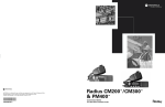
EM200
Mobile Radio
User Guide
™
EnglishTOC.fm Page 1 Tuesday, January 7, 2003 1:25 PM
CONTENTS
Getting Started . . . . . . . . . . . . . . . . . . . . . .15
Radio Overview . . . . . . . . . . . . . . . . . . . . . . 9
Radio Calls . . . . . . . . . . . . . . . . . . . . . . . . .19
Parts of the Radio . . . . . . . . . . . . . . . . . . . . . 9
Optional Enhanced Keypad Microphone
(RMN5029) . . . . . . . . . . . . . . . . . . . . . 10
On/Off/Volume Knob . . . . . . . . . . . . . . . 11
Seven Segment Display. . . . . . . . . . . . . 11
Channel Selector Buttons . . . . . . . . . . . 11
LED Indicators . . . . . . . . . . . . . . . . . . . . 11
Programmable Buttons . . . . . . . . . . . . . 12
Push-to-Talk (PTT) Button . . . . . . . . . . . 12
Microphone . . . . . . . . . . . . . . . . . . . . . . 12
Use with Enhanced Keypad Microphone
(RMN5029) . . . . . . . . . . . . . . . . . . . . . 12
Indicator Tones . . . . . . . . . . . . . . . . . . . . . . 14
Improved Audio Features . . . . . . . . . . . . . . 14
Companding. . . . . . . . . . . . . . . . . . . . . . 14
Selective Radio Inhibit . . . . . . . . . . . . . . . . .19
Repeater or Talkaround Mode . . . . . . . . . . .19
Setting the Power Level . . . . . . . . . . . . . . . .19
Setting Tight or Normal Squelch. . . . . . . . . .20
Receiving a Selective Call . . . . . . . . . . . . . .20
Receiving a Call Alert Page . . . . . . . . . . . . .20
Setting Local or Distance Mode . . . . . . . . . .20
Sending DTMF Tones . . . . . . . . . . . . . . . . .21
Computer Software Copyrights . . . . . . . . . . . 2
Safety and Warranty . . . . . . . . . . . . . . . . . . 3
CONTENTS
Product Safety and RF Exposure
Compliance . . . . . . . . . . . . . . . . . . . . . . . . . 3
Limited Warranty . . . . . . . . . . . . . . . . . . . . . . 4
Turning the Radio On or Off . . . . . . . . . . . . .15
Adjusting the Volume . . . . . . . . . . . . . . . . . .15
Selecting a Radio Channel . . . . . . . . . . . . . .15
Sending a Call . . . . . . . . . . . . . . . . . . . . . . .16
Receiving a Call . . . . . . . . . . . . . . . . . . . . . .16
Monitoring . . . . . . . . . . . . . . . . . . . . . . . . . . .16
VOX Operation . . . . . . . . . . . . . . . . . . . . . . .17
Scan . . . . . . . . . . . . . . . . . . . . . . . . . . . . . . .23
Starting or Stopping Scan. . . . . . . . . . . . . . .23
Talkback . . . . . . . . . . . . . . . . . . . . . . . . . . . .23
Deleting a Nuisance Channel . . . . . . . . . . . .24
Restoring a Channel to the Scan List . . .24
1
English
EnglishTOC.fm Page 2 Tuesday, January 7, 2003 1:25 PM
CONTENTS
Accessories . . . . . . . . . . . . . . . . . . . . . . . .25
Audio . . . . . . . . . . . . . . . . . . . . . . . . . . . . . .25
Alarm and Accessories . . . . . . . . . . . . . . . . .25
Mounting . . . . . . . . . . . . . . . . . . . . . . . . . . . .25
Antennas . . . . . . . . . . . . . . . . . . . . . . . . . . .26
Control Station . . . . . . . . . . . . . . . . . . . . . . .26
Public Address . . . . . . . . . . . . . . . . . . . . . . .26
Cables . . . . . . . . . . . . . . . . . . . . . . . . . . . . .27
Peripherals . . . . . . . . . . . . . . . . . . . . . . . . . .27
Data - CES . . . . . . . . . . . . . . . . . . . . . . . . . .27
2
English
COMPUTER SOFTWARE
COPYRIGHTS
The Motorola products described in this
manual may include copyrighted Motorola
computer programs stored in semiconductor
memories or other media. Laws in the United
States and other countries preserve for
Motorola certain exclusive rights for
copyrighted computer programs including, but
not limited to, the exclusive right to copy or
reproduce in any form the copyrighted
computer program. Accordingly, any
copyrighted Motorola computer programs
contained in the Motorola products described
in this manual may not be copied, reproduced,
modified, reverse-engineered, or distributed in
any manner without the express written
permission of Motorola. Furthermore, the
purchase of Motorola products shall not be
deemed to grant either directly or by
implication, estoppel, or otherwise, any license
under the copyrights, patents or patent
applications of Motorola, except for the normal
non-exclusive license to use that arises by
operation of law in the sale of a product.
08_SafetyNA.fm Page 3 Tuesday, January 7, 2003 1:24 PM
SAFETY AND WARRANTY
PRODUCT SAFETY AND RF
EXPOSURE COMPLIANCE
!
Caution
Before using this product, read
the operating instructions for safe
usage contained in the Product
Safety and RF Exposure booklet
enclosed with your radio.
SAFETY AND
WARRANTY
ATTENTION!
This radio is restricted to occupational use
only to satisfy FCC RF energy exposure
requirements. Before using this product, read
the RF energy awareness information and
operating instructions in the Product Safety
and RF Exposure booklet enclosed with your
radio (Motorola Publication part number
68P81095C99) to ensure compliance with RF
energy exposure limits.
For a list of Motorola-approved antennas,
batteries, and other accessories, visit the
following web site which lists approved
accessories: http://www.motorola.com/cgiss/
index.shtml.
3
English
08_SafetyNA.fm Page 4 Tuesday, January 7, 2003 1:24 PM
LIMITED WARRANTY
MOTOROLA COMMUNICATION PRODUCTS
I. WHAT THIS WARRANTY COVERS AND
FOR HOW LONG:
SAFETY AND
WARRANTY
MOTOROLA INC. (“MOTOROLA”) warrants the
MOTOROLA manufactured Communication
Products listed below (“Product”) against defects
in material and workmanship under normal use
and service for a period of time from the date of
purchase as scheduled below:
Two (2) Years
Product Accessories
One (1) Year
Motorola, at its option, will at no charge either
repair the Product (with new or reconditioned
parts), replace it (with a new or reconditioned
Product), or refund the purchase price of the
Product during the warranty period provided it is
returned in accordance with the terms of this
warranty. Replaced parts or boards are
warranted for the balance of the original
applicable warranty period. All replaced parts of
Product shall become the property of
MOTOROLA.
4
English
EM200 Mobile Units
This express limited warranty is extended by
MOTOROLA to the original end user purchaser
only and is not assignable or transferable to any
other party. This is the complete warranty for the
Product manufactured by MOTOROLA.
MOTOROLA assumes no obligations or liability
for additions or modifications to this warranty
unless made in writing and signed by an officer
of MOTOROLA. Unless made in a separate
agreement between MOTOROLA and the
original end user purchaser, MOTOROLA does
not warrant the installation, maintenance or
service of the Product.
MOTOROLA cannot be responsible in any way
for any ancillary equipment not furnished by
MOTOROLA which is attached to or used in
connection with the Product, or for operation of
the Product with any ancillary equipment, and all
such equipment is expressly excluded from this
warranty. Because each system which may use
the Product is unique, MOTOROLA disclaims
liability for range, coverage, or operation of the
system as a whole under this warranty.
08_SafetyNA.fm Page 5 Tuesday, January 7, 2003 1:24 PM
II. GENERAL PROVISIONS:
SOME STATES DO NOT ALLOW THE
EXCLUSION OR LIMITATION OF INCIDENTAL
OR CONSEQUENTIAL DAMAGES OR
LIMITATION ON HOW LONG AN IMPLIED
WARRANTY LASTS, SO THE ABOVE
LIMITATION OR EXCLUSIONS MAY NOT
APPLY.
This warranty gives specific legal rights, and
there may be other rights which may vary from
state to state.
IV. HOW TO GET WARRANTY SERVICE:
You must provide proof of purchase (bearing the
date of purchase and Product item serial number)
in order to receive warranty service and, also,
deliver or send the Product item, transportation
and insurance prepaid, to an authorized warranty
service location. Warranty service will be
provided by Motorola through one of its
authorized warranty service locations. If you first
contact the company which sold you the Product
(e.g., dealer or communication service provider),
it can facilitate your obtaining warranty service.
SAFETY AND
WARRANTY
This warranty sets forth the full extent of
MOTOROLA's responsibilities regarding the
Product. Repair, replacement or refund of the
purchase price, at MOTOROLA’s option, is the
exclusive remedy. THIS WARRANTY IS GIVEN
IN LIEU OF ALL OTHER EXPRESS
WARRANTIES. IMPLIED WARRANTIES,
INCLUDING WITHOUT LIMITATION, IMPLIED
WARRANTIES OF MERCHANTABILITY AND
FITNESS FOR A PARTICULAR PURPOSE,
ARE LIMITED TO THE DURATION OF THIS
LIMITED WARRANTY. IN NO EVENT SHALL
MOTOROLA BE LIABLE FOR DAMAGES IN
EXCESS OF THE PURCHASE PRICE OF THE
PRODUCT, FOR ANY LOSS OF USE, LOSS OF
TIME, INCONVENIENCE, COMMERCIAL
LOSS, LOST PROFITS OR SAVINGS OR
OTHER INCIDENTAL, SPECIAL OR
CONSEQUENTIAL DAMAGES ARISING OUT
OF THE USE OR INABILITY TO USE SUCH
PRODUCT, TO THE FULL EXTENT SUCH MAY
BE DISCLAIMED BY LAW.
III. STATE LAW RIGHTS:
5
English
08_SafetyNA.fm Page 6 Tuesday, January 7, 2003 1:24 PM
SAFETY AND
WARRANTY
V. WHAT THIS WARRANTY DOES NOT
COVER:
6
English
H
A Product which, due to illegal or
unauthorized alteration of the software/
firmware in the Product, does not function in
accordance with MOTOROLA’s published
specifications or the FCC type acceptance
labeling in effect for the Product at the time
the Product was initially distributed from
MOTOROLA.
A
Defects or damage resulting from use of the
Product in other than its normal and
customary manner.
B
Defects or damage from misuse, accident,
water, or neglect.
C
Defects or damage from improper testing,
operation, maintenance, installation,
alteration, modification, or adjustment.
I
Scratches or other cosmetic damage to
Product surfaces that does not affect the
operation of the Product.
D
Breakage or damage to antennas unless
caused directly by defects in material
workmanship.
J
Normal and customary wear and tear.
VI. PATENT AND SOFTWARE PROVISIONS:
E
A Product subjected to unauthorized
Product modifications, disassemblies or
repairs (including, without limitation, the
addition to the Product of non-Motorola
supplied equipment) which adversely affect
performance of the Product or interfere with
Motorola's normal warranty inspection and
testing of the Product to verify any warranty
claim.
MOTOROLA will defend, at its own expense, any
suit brought against the end user purchaser to
the extent that it is based on a claim that the
Product or parts infringe a United States patent,
and MOTOROLA will pay those costs and
damages finally awarded against the end user
purchaser in any such suit which are attributable
to any such claim, but such defense and
payments are conditioned on the following:
F
Product which has had the serial number
removed or made illegible.
A
G
Freight costs to the repair depot.
that MOTOROLA will be notified promptly in
writing by such purchaser of any notice of
such claim;
B
that MOTOROLA will have sole control of the
defense of such suit and all negotiations for
08_SafetyNA.fm Page 7 Tuesday, January 7, 2003 1:24 PM
its settlement or compromise; and
C
MOTOROLA will have no liability with respect to
any claim of patent infringement which is based
upon the combination of the Product or parts
furnished hereunder with software, apparatus or
devices not furnished by MOTOROLA, nor will
MOTOROLA have any liability for the use of
ancillary equipment or software not furnished by
MOTOROLA which is attached to or used in
connection with the Product. The foregoing
states the entire liability of MOTOROLA with
respect to infringement of patents by the Product
or any parts thereof.
Laws in the United States and other countries
preserve for MOTOROLA certain exclusive rights
for copyrighted MOTOROLA software such as
the exclusive rights to reproduce in copies and
distribute copies of such Motorola software.
MOTOROLA software may be used in only the
Product in which the software was originally
embodied and such software in such Product
may not be replaced, copied, distributed,
modified in any way, or used to produce any
derivative thereof. No other use including,
without limitation, alteration, modification,
reproduction, distribution, or reverse engineering
of such MOTOROLA software or exercise of
rights in such MOTOROLA software is permitted.
No license is granted by implication, estoppel or
otherwise under MOTOROLA patent rights or
copyrights.
SAFETY AND
WARRANTY
should the Product or parts become, or in
MOTOROLA’s opinion be likely to become,
the subject of a claim of infringement of a
United States patent, that such purchaser
will permit MOTOROLA, at its option and
expense, either to procure for such
purchaser the right to continue using the
Product or parts or to replace or modify the
same so that it becomes non-infringing or to
grant such purchaser a credit for the Product
or parts as depreciated and accept its
return. The depreciation will be an equal
amount per year over the lifetime of the
Product or parts as established by
MOTOROLA.
VII.GOVERNING LAW:
This Warranty is governed by the laws of the
State of Illinois, USA.
7
English
08_SafetyNA.fm Page 8 Tuesday, January 7, 2003 1:24 PM
SAFETY AND
WARRANTY
Notes:
8
English
03_Overview.fm Page 9 Tuesday, January 7, 2003 1:22 PM
RADIO OVERVIEW
PARTS OF THE RADIO
Push-To-Talk
(PTT) Button
Microphone
Red/Yellow/Green
LED Indicators
On/Off/Volume
Knob
7-Segment
Display
Speaker
E
Channel Selector
Buttons
Programmable
Button 1 (P1)
Programmable
Button 2 (P2)
RADIO OVERVIEW
Microphone
Jack
High Power
Indicator
9
English
03_Overview.fm Page 10 Tuesday, January 7, 2003 1:22 PM
Optional Enhanced Keypad Microphone
(RMN5029)
Your radio may be ordered with an optional
DTMF (Dual-Tone Multi-Frequency)
microphone that has a direct entry keypad.
This keypad microphone has three
programmable buttons (A, B, C) below the
keypad that can be programmed to
conveniently activate select radio features also
available for the programmable g and h
buttons.
DTMF Keypad
RADIO OVERVIEW
Push-to-Talk
(PTT) button
10
English
Programmable
Buttons
(A, B, C)
03_Overview.fm Page 11 Tuesday, January 7, 2003 1:22 PM
On/Off/Volume Knob
Basic Features
Turns the radio on or off, and adjusts the
radio’s volume.
Radio Call
Seven Segment Display
Red
Transmitting
The seven segment display indicates what
channel is active and the power level.
Flashing Red
Receiving
Flashing Red
Channel Busy
Channel Selector Buttons
Scan
Used for channel selection. Pressing a
channel selector button causes its
associated channel indicator to light.
LED State/Color
Flashing Green
Indication
Scanning for activity
Call Alert
Flashing Yellow
Indicates receiving a Call Alert
Selective Call
Each press of the
button increments the
channel. Each press of the
button
decrements the channel.
Flashing Yellow
LED Indicators
Yellow
Indicates power up, transmit, receive, scan,
monitor status, busy, power, Call Alert™
receive, and Selective Call receive.
High/Low Power
Indicates receiving a Selective
Call
Sticky Monitor/Open Squelch
While monitoring
Indicates High Power
Dot Not On
Display
Indicates Low Power
RADIO OVERVIEW
Dot on Display
11
English
03_Overview.fm Page 12 Tuesday, January 7, 2003 1:22 PM
Programmable Buttons
Your radio has two programmable buttons.
Your dealer can program these buttons as
shortcuts to various radio features.
Check with your dealer for a complete list of
functions your radio supports.
RADIO OVERVIEW
Programmable buttons include the g and
h buttons (see page 9).
Some buttons can access up to two features,
depending on the type of button press:
•
short press—quickly pressing and releasing
the programmable buttons
•
long press—pressing and holding the
programmable buttons for a period of time
(default 1 1/2 seconds or programmed
value)
•
hold down—pressing and holding down the
programmable buttons while checking
status or making adjustments
Also, where appropriate, have your dealer
indicate whether the button press requires a short
press, a long press, or needs to be held down.
Push-to-Talk (PTT) Button
Press and hold down this button on the
microphone to talk (transmit); release it to listen.
Microphone
Hold the microphone 1 to 2 inches (2.5 to
5 cm) from your mouth, and speak clearly
into it.
Use with Enhanced Keypad Microphone
(RMN5029)
DTMF Keypad
A summary of programmable radio features
and corresponding page references appears
beginning on page 13.
In the “Button” column, have your dealer record
the name of the programmable button next to
the feature that has been programmed to it.
12
English
The dealer can use the abbreviations (P1, P2)
shown in the radio illustration on page 9.
Programmable
Buttons
(A, B, C)
These keys are used to:
•
Send DTMF tones (see page 21)
•
Directly access preprogrammed features
03_Overview.fm Page 13 Tuesday, January 7, 2003 1:22 PM
Function
Short Press
Long Press
Volume Set
Sound a tone for adjusting your radio’s volume
Sticky Monitor
Toggle silent monitor
operation (also turn off
open squelch monitor
when it has been
activated).
Repeater/
Talkaround
Hold Down
level.†
Turn on open squelch
monitor.
Page
15
16
Toggle between using a repeater or transmitting directly
to another radio.†
—
19
Power Level
Toggle transmit power level between High and Low. An
indication for high power is a dot on the display. The dot
does not appear while in low power.†
—
19
Voice Operated
Transmission
(VOX)
Toggle VOX on and off.†
—
17
Squelch
Toggles your radio’s squelch level between tight and
normal squelch.
—
20
Local/Distance
Toggle between local mode and distance mode.†
—
20
Scan/Nuisance
Channel Delete
Toggle scan on and off.
—
23
†
RADIO OVERVIEW
—
Delete a nuisance channel
while scanning.
Button
This function is activated by EITHER a short OR a long press, but not both.
13
English
03_Overview.fm Page 14 Tuesday, January 7, 2003 1:22 PM
INDICATOR TONES
High pitched tone
Repeater/
Talkaround
Positive
Indicator Tone
Does not use
repeater
Negative
Indicator Tone
Uses repeater
VOX
VOX enabled
VOX disabled
Button
Low pitched tone
Self Test Pass Tone
Local/Distance Local Mode
Self Test Fail Tone
Distance Mode
IMPROVED AUDIO FEATURES
Companding
Positive Indicator Tone
RADIO OVERVIEW
Negative Indicator Tone
Some programmable buttons use tones to
indicate one of two modes:
Button
Scan
Power Level
Squelch
14
English
Positive
Indicator Tone
Start scan
High power
selected
Tight Squelch
Negative
Indicator Tone
Stop scan
Low power
selected
Normal Squelch
Companding is a feature that allows further
improvement of voice quality. It compresses
your voice at transmission, and expands it
when receiving while simultaneously reducing
extraneous noise. However, to enjoy this
benefit, all transmitting and receiving radios
must have this feature activated.
04_GetStarted.fm Page 15 Tuesday, January 28, 2003 2:35 PM
TURNING THE RADIO ON OR OFF
On/Off/Volume
Control Knob
ON
OFF
Rotate the On/Off/
Volume Control knob
clockwise. If power-up
is successful, you will
hear the Self-Test Pass
Tone (
) and
see the green LED
indicator light
momentarily.
Rotate the On/Off/
Volume Control knob
counterclockwise until
you hear a click and both
the display and LED indicators turn off.
If the radio fails to
power up, you will hear
the Self Test Fail Tone
(
).
Turn the On/Off/Volume Control knob
clockwise to increase the volume, or
counterclockwise to decrease the volume.
–or–
Note: Your dealer can preprogram one of the
programmable buttons to Volume Set.
1
Hold down the Volume Set button (see
page 13). You will hear a continuous tone.
2
Turn the On/Off/Volume Control knob to the
desired volume level.
3
Release the Volume Set button.
GETTING STARTED
ADJUSTING THE VOLUME
GETTING STARTED
SELECTING A RADIO CHANNEL
Your radio offers four or eight channels.
Note: Due to government regulations, some
channels may not be programmed.
See your dealer for more information.
To Select a Channel
Press the
button or
the desired channel.
button to select
15
English
GETTING STARTED
04_GetStarted.fm Page 16 Tuesday, January 28, 2003 2:35 PM
SENDING A CALL
1
Turn your radio on.
2
Select the desired channel.
3
Hold the microphone vertically 1 to 2 inches
(2.5 to 5 cm) from your mouth. Press the PTT
button to talk; release it to listen.
MONITORING
It is important to monitor traffic before
transmitting to ensure that you do not “talk
over” someone who is already transmitting.
1
A short press of the preprogrammed Monitor
button places the radio in Sticky Permanent
Monitor mode.
•
RECEIVING A CALL
1
Turn your radio on.
2
Adjust the radio’s volume, if necessary (see
page 15).
3
Select the desired channel.
4
To respond, hold the microphone vertically 1
to 2 inches (2.5 to 5 cm) from your mouth.
Press the PTT button to talk; release it to listen.
16
English
You hear a high-pitched tone.
A short press of the Monitor button cancels
Sticky Permanent Monitor mode and returns
the radio to normal operation.
3
To place the radio in open squelch mode,
press and hold the preprogrammed Monitor
button until you hear a high-pitched tone.
4
Momentarily press the Monitor button to
return to normal operation.
04_GetStarted.fm Page 17 Tuesday, January 28, 2003 2:35 PM
GETTING STARTED
VOX OPERATION
When hands-free operation is desired, your
radio can transmit by voice alone using the
VOX feature when you speak through a voice
activated external microphone that is
connected to your radio.
1
To enable or disable VOX operation, press the
preprogrammed VOX button (see page 13).
Note:
Pressing the PTT button disables
VOX.
–or–
2
3
Select a channel that has been
preprogrammed by your dealer to enable
VOX.
Note:
You do not need to press a preprogrammed VOX button.
Note:
Pressing the PTT button disables
VOX.
Select a channel that has not been
preprogrammed by your dealer to disable
VOX.
17
English
GETTING STARTED
04_GetStarted.fm Page 18 Tuesday, January 28, 2003 2:35 PM
Notes:
18
English
05_RadioCall.fm Page 19 Tuesday, January 7, 2003 1:23 PM
RADIO CALLS
–or–
•
SELECTIVE RADIO INHIBIT
Your radio is equipped with a security feature
that can temporarily render the unit inoperative
when an inhibit signal is sent from the base
station.
This feature is commonly used to disable
radios:
In case of theft
When your vehicle is being serviced
For system control reasons
Note: When your radio has been disabled by
the base station, the seven segment
display indicates 0 and all controls will
be inoperative except for the On/Off
button.
REPEATER OR TALKAROUND
MODE
Talkaround Mode enables you to communicate
with another radio when either:
•
To select either Repeater Mode or Talkaround
Mode:
Press the preprogrammed Repeater/
Talkaround button (see page 13) to toggle
between Repeater Mode and Talkaround
Mode.
RADIO CALLS
•
•
•
Your radio is out of the repeater’s range but
within communicating distance of another
radio. An audible indicator is heard when
changing between modes.
SETTING THE POWER LEVEL
Each channel in your radio has a predefined
transmit power level that can be changed.
•
•
High power
Low power
To set the power level, press the
preprogrammed Power Level button (see
page 13) to toggle between low and high. A
dot appears on the display indicating high
power.
The repeater is not operating
19
English
RADIO CALLS
05_RadioCall.fm Page 20 Tuesday, January 7, 2003 1:23 PM
SETTING TIGHT OR NORMAL
SQUELCH
RECEIVING A CALL ALERT PAGE
Use this feature to filter out nuisance
(unwanted) calls and/or background noise.
However, tightening squelch could cause calls
from remote locations to be filtered out as well.
In this case, normal squelch may be more
desirable.
•
The yellow LED indicator flashes, if programmed by your dealer.
•
You hear four high-pitched tones.
Press the preprogrammed Squelch button
(see page 13) to toggle between tight and
normal squelch.
RECEIVING A SELECTIVE CALL
When you receive a selective call:
•
The yellow LED indicator flashes, if programmed by your dealer.
•
You hear two high-pitched tones.
To answer the call, press the PTT button.
20
English
When you receive a Call Alert page:
To answer the page, press the PTT button; to
cancel the page, press any other key.
SETTING LOCAL OR DISTANCE
MODE
Use this feature between Local mode (low
sensitivity) and Distance mode (normal
sensitivity). When Local mode is set, you will
not hear week transmissions. When Distance
mode is set you will hear all transmissions,
including weaker signals.
Press the preprogrammed Local/Distance
button (see page 13) to toggle between Local
and Distance mode.
05_RadioCall.fm Page 21 Tuesday, January 7, 2003 1:23 PM
SENDING DTMF TONES
Use with Enhanced Keypad Microphone
(RMN5029)
Use this feature to send DTMF tones to a
repeater.
Press and hold the microphone’s PTT button.
2
Press and release the required DTMF
buttons.
3
Release the microphone’s PTT button.
RADIO CALLS
1
21
English
05_RadioCall.fm Page 22 Tuesday, January 7, 2003 1:23 PM
RADIO CALLS
Notes:
22
English
06_Scan.fm Page 23 Tuesday, January 7, 2003 1:24 PM
SCAN
3
You can monitor multiple channels and receive
any calls that are transmitted on them.
Channels can be programmed into a scan list
by your dealer. Your radio automatically
switches to a scan list channel when it detects
activity on it.
STARTING OR STOPPING SCAN
The green LED indicator blinks during a scan
operation and stops blinking when the radio
switches to a channel.
You can start or stop a scan operation by:
1
To start or stop a scan operation, press the
preprogrammed Scan button (see page 13).
Select a channel that has not been
preprogrammed by your dealer to stop Auto
Scan.
TALKBACK
The Talkback feature allows you to respond to a
transmission while scanning. If transmission is
detected on a channel while scanning, the radio
will stop on that channel for a preprogrammed
period of time. During this “hangtime” you may
respond by pressing the PTT button.
Notes: If transmission ceases or if the PTT
button is not pressed for a preprogrammed duration, the radio continues
to scan. The LED scan indicator stops
blinking while the radio is in hangtime.
–or–
Select a channel that has been
preprogrammed by your dealer to start Auto
Scan.
Note:
SCAN
2
You do not need to press a preprogrammed Scan button.
23
English
06_Scan.fm Page 24 Tuesday, January 7, 2003 1:24 PM
DELETING A NUISANCE CHANNEL
Note: Your dealer must have preprogrammed
a button to Nuisance Delete to access
this feature.
If a channel continually generates unwanted
calls or noise (a “nuisance” channel), you can
temporarily remove it from the scan list:
1
While the radio is on the Nuisance Channel,
press the preprogrammed Nuisance
Channel Delete button until you hear a tone.
2
Release the Nuisance Channel Delete
button. The nuisance channel is deleted.
Note: You cannot delete a priority channel or
last remaining channel in the scan list.
SCAN
Restoring a Channel to the Scan List
1
Press the Scan button to stop the scan.
2
Press the Scan button again to start scanning
again. The Deleted Nuisance Channel is
restored to the scan list.
24
English
09_Accessory.fm Page 25 Wednesday, January 29, 2003 10:56 AM
Motorola offers a number of accessories to
enhance the productivity of your two-way radio.
Many of the available accessories are listed
below.
AUDIO
HMN3596
Standard Microphone
HMN1035
Heavy Duty Microphone
RMN5029
Enhanced Keypad Microphone
RMN5018
Mag One Microphone
(6 months warranty only)
REX4617
Telephone Style Handset Kit
GMMN4065 Visor Microphone (Omni-Direction)
RMN4027
Visor Microphone - High Noise
(Uni-Direction)
RSN4001
External Speaker 13 W
HSN8145
External Speaker 7.5 W
HLN9073
Microphone Hang-up Clip (requires install)
HLN9414
Microphone Hang-up Clip (Universal - no
install required)
ALARM AND ACCESSORIES
RLN4856
Footswitch with Remote PTT
RLN4857
Pushbutton with Remote PTT
RLN4858
Gooseneck PTT
RLN4836
External PTT with Emergency Footswitch
HLN9328
External Alarm Relay (used in conjuction
with GLN7282)
GLN7282
Buzzer Kit (used in conjunction with
HLN9328)
ACCESSORIES
ACCESSORIES
MOUNTING
GLN7324
Low Profile Mounting Bracket
GLN7317
High Profile Mounting Bracket
FTN6083
DIN Mount
HLN8097
Removable Slide Mount with Mini-U
Connector
HLN9227
8 in. Gooseneck Trunnion
RLN4779
Keylock Mounting Bracket
25
English
09_Accessory.fm Page 26 Tuesday, January 28, 2003 2:05 PM
ACCESSORIES
ANTENNAS
HAD4006
VHF 136-144 MHz, 1/4 Wave Roof Mount
HAD4007
VHF 144-150.8 MHz, 1/4 Wave Roof
Mount
HAD4008
VHF 150.8-162 MHz, 1/4 Wave Roof
Mount
CONTROL STATION
HAD4009
VHF 162-174 MHz, 1/4 Wave Roof Mount
HPN4002
Desktop Power Supply 1-25 W
RAD4000
VHF 136-174 MHz, 3 dB Gain (no mount)
HPN4001
Desktop Power Supply 25-60 W
HAD4014
VHF 140-174 MHz, 3.5 dB Gain Roof
Mount
HMN3000
Black Desk Microphone
RLN5390
Desktop Tray with Speaker
UHF 403-430 MHz, 1/4 Wave Roof
Mount
RLN5391
Desktop Tray without Speaker
RLN5392
Low Power Control Station Kit (1-25 W)
(includes power supply, desktop tray, and
desk mic)
RLN5393
High Power Control Station Kit (25-60 W)
(includes power supply, desktop tray, and
desk mic)
HAE4002
TAE6053
UHF 430-450 MHz, 1/4 Wave Roof
Mount
HAE4003
UHF 450-470 MHz, 1/4 Wave Roof
Mount
HAE4004
UHF 470-512 MHz, 3.5 dB Gain Roof
Mount
HAE4010
UHF 406-420 MHz, 3.5 dB Gain Roof
Mount
HAE4011
UHF 450-470 MHz, 3.5 dB Gain Roof
Mount
PUBLIC ADDRESS
HAE4012
UHF 470-494 MHz, 3.5 dB Gain Roof
Mount
RLN5288
HAE4013
UHF 494-512 MHz, 3.5 dB Gain Roof
Mount
HKN9324_R Speaker Cable for PA (15 ft)
RAE4004_RB UHF 445-470 MHz, 5 dB Gain Roof
Mount
26
English
RAE4004_MB UHF 445-470 MHz, 5 dB Gain Magnetic
Mount
HSN1000
Public Address Kit (includes switch box
and cabling)
External Speaker, 6 W for public address
09_Accessory.fm Page 27 Tuesday, January 28, 2003 2:05 PM
CABLES
Igition Switch Cable
HKN4137
Low Power Cable to Battery (1-25 W)
HKN4191
High Power Cable to Battery (25-60 W)
Credit Card Software
RDN7371
Credit Card Reader
RDN7738
Serial Breakout Unit (multiple modems)
RDN7739
Flying Lead Cable, 3 ft.
RDN7740
Flying Lead Cable, 15 ft.
ACCESSORIES
HKN9327
RDN7379
PERIPHERALS
HLN3948
Basic RICK (Repeater Interface Comm Kit)
HLN3333
RICK (Repeater Interface Comm Kit)
DATA - CES
RDN7364
Base Modem
RDN7367
Mobile Display Terminal with GPS
RDN7368
Mobile Display Terminal
RDN7369
Stand Alone Modem with GPS
RDN7370
Interface Cable, 3 ft
RDN7376
Interface Cable, 15 ft
RDN7372
Fixed Mount GPS Active Antenna
RDN7373
Mobile Printer
RDN7374
Programming Software for CES Equipment
RDN7380
Mobile Programming Hardware
RDN7375
Magnetic Mount GPS Antenna
RDN7377
MAPS (US) Regional
RDN7378
AVL Messaging Statue Software
27
English
09_Accessory.fm Page 28 Tuesday, January 28, 2003 2:05 PM
ACCESSORIES
Notes:
28
English
10_QR-Card.fm Page 29 Tuesday, January 28, 2003 2:36 PM
Turning the Radio On or Off
1. Rotate the On/Off/Volume Control knob clockwise. You will hear the self-test
pass tone and see the green LED indicator light momentarily.
2. Rotate the On/Off/Volume Control knob counterclockwise until you hear a
click and both the display and the LED indicators turn off.
Adjusting the Volume
EM200™ Quick Reference Card
Record the functions for your radio’s programmable buttons in the table
provided below. For further information, see page 13 of this User Guide.
1. Turn the On/Off/Volume Control knob clockwise to increase the volume, or
counterclockwise to decrease the volume.
Selecting a Radio Channel
1. Press the
or
button to select the desired channel.
Red/Yellow/Green
LED Indicators
7-Segment
Display
On/Off/Volume
Knob
Sending a Call
1. Turn radio on and select appropriate channel.
2. Press PTT button, hold the microphone 1 to 2 inches (2.5 to 5 cm) from your
mouth, and speak clearly into it.
3. Release PTT button to listen.
E
Receiving a Call
1. Turn radio on and adjust volume to the desired level.
2. Select desired channel.
3. To respond to an incoming call, press PTT button, hold the microphone 1 to 2
inches (2.5 to 5 cm) from your mouth, and speak clearly into it.
Starting or Stopping Scan
1. Press the preprogrammed Scan button to start scan. The green LED indictor
blinks during scan operation. Or, select a channel that has been preprogrammed to start Auto Scan.
2. Press the Scan button again to stop scan. Or, select a channel that has not
been preprogrammed to stop Auto Scan.
Deleting a Nuisance Channel During Scanning
1. While radio is on a nuisance channel, hold down preprogrammed Nuisance
Delete button until you hear a tone.
2. Release Nuisance Delete button.
Microphone
Jack
Button
Channel Selector
Buttons
Function
Programmable
Button 1 (P1)
Short Press
Programmable
Button 2 (P2)
Long Press
High Power
Indicator
Hold Down
Page
10_QR-Card.fm Page 30 Tuesday, January 28, 2003 2:36 PM
LED Indicators
Audio Indicators for Programmable Buttons
LED State/Color
Indication
Radio Call
Red
Transmitting
Flashing Red
Receiving
Flashing Red
Channel Busy
Scan
Flashing Green
Scanning for activity
Call Alert
Flashing Yellow
Indicates receiving a Call Alert
Selective Call
Flashing Yellow
Indicates receiving a Selective Call
Sticky Monitor/Open Squelch
Yellow
While monitoring
High/Low Power
Dot on Display
Indicates High Power
Dot Not On
Display
Indicates Low Power
Programmable
Button
Scan
Power Level
Squelch
Repeater/
Talkaround
Positive Indicator
Tone
Start scan
High power selected
Tight Squelch
Does not use
repeater
Negative Indicator
Tone
Stop scan
Low power selected
Normal Squelch
Uses repeater
VOX
VOX enabled
VOX disabled
Local/Distance
Local Mode
Distance Mode
MOTOROLA and the Stylized M Logo are registered in the U.S. Patent and Trademark Office.
All other product or service names are the property of their respective owners.
© Motorola, Inc. 2003. All Rights Reserved. Printed in U.S.A.
*HKLN4212A*
HKLN4212A