1
BNP-B2231A (ENG)
600L Series
INSTRUCTION MANUAL
Introduction
This instruction manual mainly targets lathe. This is to be used as a guide when using
MELDAS 600L Series, the software-fixed type of CNC (NC hereafter) systems which are
designed to execute high-performance contour control.
This instruction manual describes the screen operations of the MELDAS 600L Series.
Read this instruction manual thoroughly before using.
This manual is written assuming that all functions of the MELDAS 600L Series are
provided. However, depending on the NC unit, all functions and options may not
necessarily be provided. Therefore, always check the specifications issued by the
machine manufacturer before starting use.
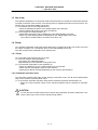
Read the "Precautions for Safety" given on the next page to ensure safe use of the NC.
Details described in this manual
CAUTION
For items described in "Restrictions" or "Usable State", the instruction manual issued by
the machine manufacturer takes precedence over this manual.
Items not described in this manual must be interpreted as "Not Possible".
This manual has been written on the assumption that all option functions are added.
Refer to the specifications issued by the machine manufacturer before starting use.
Refer to the manuals issued by the machine manufacturer for each machine tool
explanation.
Some screens and functions may differ or may not be usable depending on the NC
version.
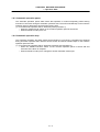
General precautions
(1) Refer to the documentation below for details on programming:
MELDAS 600L Series Programming Manual ....................................... BNP-B2232
(2) The font used with MELDAS 600L is Meldas Gothic, developed by RICOH COMPANY LTD.
under the license agreement with RYOBI IMAGIX CO.
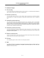
Precautions for Safety
Always read the specifications issued by the machine manufacturer, this manual, related
manuals and attached documents before installation, operation, programming,
maintenance or inspection to ensure correct use.
Understand this numerical controller, safety items and cautions before using the unit.
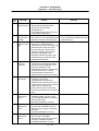
This manual ranks the safety precautions into "DANGER", "WARNING" and "CAUTION".
DANGER
When the user may be subject to imminent fatalities or major
injuries if handling is mistaken.
WARNING
When the user may be subject to fatalities or major injuries if
handling is mistaken.
CAUTION
When the user may be subject to injuries or when physical damage
may occur if handling is mistaken.
Note that even items ranked as "
CAUTION", may lead to major results depending on
the situation. In any case, important information that must always be observed is
described.
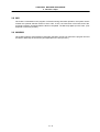
DANGER
Not applicable in this manual.
WARNING
Not applicable in this manual.
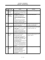
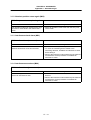
CAUTION
1. Items related to product and manual
For items described as "Restrictions" or "Usable State" in this manual, the instruction
manual issued by the machine manufacturer takes precedence over this manual.
Items not described in this manual must be interpreted as "Not Possible".
This manual has been written on the assumption that all option functions are added.
Refer to the specifications issued by the machine manufacturer before starting use.
Refer to the manuals issued by the machine manufacturer for each machine tool
explanation.
Some screens and functions may differ or may not be usable depending on the NC
version.
2. Items related to installation and assembly
Always ground the signal cable to ensure stable operation of the system. Ground the NC unit,
power distribution panel and machine to a one-point ground to establish the same potential.
CAUTION
3. Items related to preparations before use.
Always set the stored stroke limit. If not set, the axis could collide at the machine end.
Always turn the power OFF before connecting/disconnecting the I/O device cables.
The NC and I/O device could be damaged if the cable is connected/disconnected in
the power ON state.
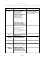
4. Items related to screen operation
If the tool offset amount is changed during automatic operation (including single block
stop), the amount will be validated from the next block or several blocks following
commands.
Pay close attention to the sequence operation when carrying out forced data setting
(forced output) in the I/F diagnosis screen.
All of the various data in the NC memory is erased when formatting. Be sure to use the
transfer function to transfer all the necessary data to another storage device before
formatting.
The actual data is rewritten when parameter input and tool compensation amount
change commands (40 sets or more) are issued using a G10 command during graphic
check.
To prevent the influence of data loss and data transformation over the line, always
carry out data comparison after transferring a machining program.
Do not change the machine parameters without prior consent from the machine
manufacturer.
If initialization is executed on the MELDAS Diagnosis screen before the data is saved,
all of the diagnosis data will be erased.
If another screen is opened before saving the data on the MELDAS Diagnosis screen,
the set diagnosis information parameters will all be invalidated.
If an alarm occurs, remove the cause, and confirm that the operation signal is not
being input. Then secure the safety and reset the alarm before restarting operation.
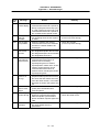
5. Items related to programming
If there is no value after the G command, the operation will be the "G00" operation
when the program is run due to key chattering, etc., during editing.
" ; " "EOB" and " % " "EOR" are symbols used for explanation. The actual codes for
ISO are: "CR, LF", or "LF" and "%".
Programs created on the Edit screen are stored in the NC memory in a "CR, LF"
format, but programs created with external devices such as the FLD or RS-232C may
be stored in an "LF" format.
The actual codes for EIA are: "EOB (End Of Block)" and "EOR (End Of Record)".
Do not change the Fixed cycle program without prior consent from the machine
manufacturer.
CAUTION
6. Items related to operation
Program so the mirror image function is turned ON/OFF at the mirror image center.
The mirror image center will deviate if the function is turned ON/OFF at a position
other than the mirror image center.
Do not enter the movable range of the machine during automatic operation. Make
sure not to place hands, legs or face near the spindle during rotation.
Always carry out dry run operation before actual machining, and confirm the
machining program, tool offset amount and workpiece coordinate system offset
amount.
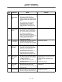
7. Items related to faults and errors
If the BATTERY LOW warning is output, save the machining programs, tool data and
parameters to an I/O device, and then replace the battery. If the BATTERY alarm
occurs, the machining programs, tool data and parameters may be damaged. After
replacing the battery, reload each data item.
If the axis overruns or makes an abnormal noise, press the emergency stop button
immediately, and stop the axis.
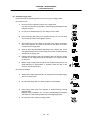
8. Items related to maintenance
Do not apply voltages on the connector other than those indicated in this manual.
Doing so may lead to destruction or damage.
Incorrect connections may damage the devices, so connect the cables to the
specified connectors.
Do not connect or disconnect the connection cables between each unit while the
power is ON.
Do not connect or disconnect any PCB while the power is ON.
Do not replace the battery while the power is ON.
Do not short-circuit, charge, overheat, incinerate or disassemble the battery.
Dispose of the spent battery according to local laws.
Do not replace the cooling fan while the power is ON.
Dispose of the old cooling fan according to local laws.
Do not replace the HDD while the power is ON.
Dispose of the old HDD according to local laws.
Do not replace the backlight while the power is ON.
Dispose of the spent backlights according to local laws.
CONTENTS
CHAPTER 1 SCREEN OPERATIONS
1. Operating the Setting Display Unit...........................................................................
1.1 Setting display unit................................................................................................
1.2 Screen transition diagram.....................................................................................
1.3 Screen selection procedures ................................................................................
1.4 Setting data ..........................................................................................................
1.4.1 Setting numerals and alphabetic characters.................................................
1.4.2 Inputting operations ......................................................................................
1.5 Screen operations ................................................................................................
1.5.1 Setting a manual value command (S, M, T, B) .............................................
1.5.2 Changing the valid area ................................................................................
1.5.3 Changing the absolute value/incremental value setting................................
1.5.4 Changing the display axis .............................................................................
1.5.5 Selecting a device, directory and file.............................................................
1.5.6 Changing the display system ........................................................................
1.5.7 Changing the menu ......................................................................................
1.5.8 Menu operations ...........................................................................................
2. Monitor (Operation) Screens ......................................................................................
2.1 Position Display 1 screen (Position display1 screen) ...........................................
2.1.1 Changing the counter display .......................................................................
2.1.2 Executing manual value commands .............................................................
2.1.3 Presetting the counter (Counter set, origin set) ............................................
2.1.4 Axis display during G110 (cross axis command) execution.......................
2.2 Position Display 2 screen (Position display2 screen) ...........................................
2.2.1 Setting manual value commands..................................................................
2.2.2 Changing the counter display .......................................................................
2.2.3 Correcting the buffer .....................................................................................
2.2.4 Changing the display axis .............................................................................
2.3 Position Display 3 screen (Position display3 screen) ...........................................
2.3.1 Changing the counter display .......................................................................
2.3.2 Setting the cumulative time...........................................................................
2.4 Operation Search screen......................................................................................
2.4.1 Executing an operation search .....................................................................
2.5 Graphics screen (Graphic trace screen)...............................................................
2.5.1 Tracing and displaying the machine position ................................................
2.5.2 Changing the display range ......................................................................
2.5.3 Changing the display mode ......................................................................
2.5.4 Changing the axis display direction...........................................................
2.5.5 Changing the drawing scale for each axis.................................................
2.6 Common Variable screen .....................................................................................
2.6.1 Common variables 1, common variables 2 ...............................................
2.6.2 Setting common variables.............................................................................
2.6.3 Copying/pasting common variables ..............................................................
2.6.4 Erasing common variables............................................................................
2.7 Local Variable screen ...........................................................................................
2.7.1 Displaying local variables..............................................................................
2.8 PLC Switch screen ...............................................................................................
2.8.1 Turning PLC switches ON/OFF ....................................................................
2.9 Control Parameter screen (Control param screen) ..............................................
i
I−1
I–1
I–6
I–7
I–8
I–8
I – 11
I – 12
I – 12
I – 14
I – 15
I – 16
I – 17
I – 23
I – 24
I – 25
I – 26
I – 26
I – 28
I – 29
I – 29
I – 31
I – 33
I – 34
I – 34
I – 35
I – 37
I – 38
I – 43
I – 43
I – 44
I – 46
I – 48
I – 49
I – 52
I – 56
I – 57
I – 57
I – 58
I – 60
I – 61
I – 62
I – 63
I – 64
I – 66
I – 68
I – 69
I – 70
2.9.1 Turning Control parameters ON/OFF ...........................................................
2.9.2 Control parameter details..............................................................................
3. Setup Screens .............................................................................................................
3.1 Tool Wear Data screen (Tool wear data screen)................................................
3.1.1 Setting the tool wear data .............................................................................
3.1.2 Erasing the tool wear data ............................................................................
3.2 Tool Data screen (Too data screen) .................................................................
3.2.1 Setting the tool data..................................................................................
3.2.2 Erasing the tool data.................................................................................
3.2.3 Measuring the tool length..........................................................................
3.3 Tool Life Management screen (Tool life manage screen).................................
3.3.1 Tool life management I..........................................................................
3.3.2 Tool life management II ........................................................................
3.4 Coordinate System Offset screen (Coord offset screen)......................................
3.4.1 Setting the coordinate system offset data.....................................................
3.4.2 Erasing the coordinate system offset data....................................................
3.4.3 Setting the workpiece coordinate zero point .................................................
3.4.4 Setting the manual value command .............................................................
3.4.5 Changing the coordinate system display ......................................................
3.5 Data Input/Output screen (Input/Output screen) ..................................................
3.5.1 Selecting a device, directory and file.............................................................
3.5.2 Transferring a file..........................................................................................
3.5.3 Comparing files (Compare)...........................................................................
3.5.4 Erasing a file .................................................................................................
3.5.5 Changing a file name (Rename)...................................................................
3.5.6 Creating a directory.......................................................................................
3.5.7 Formatting an FLD........................................................................................
3.5.8 List of file names...........................................................................................
3.5.9 Edit lock B and C ..........................................................................................
3.3.10 Data protect keys..........................................................................................
3.6 Parameter screens ...............................................................................................
3.6.1 Setting the parameters .................................................................................
3.6.2 Copying/pasting parameters.........................................................................
3.7 User parameter details .........................................................................................
3.7.1 Axis Parameter (Axis param screen) ............................................................
3.7.2 Setup Parameter (Setup param screen) ...................................................
3.7.3 Input/Output Parameter (I/O param screen) .................................................
3.7.4 Barrier Data (Barrier data screen).............................................................
3.7.5 RS-232C I/O device parameter setting examples and cable connections....
4. Edit Screens .................................................................................................................
4.1 Edit screen (Edit screen) ......................................................................................
4.1.1 Creating a new machining program..............................................................
4.1.2 Editing a program .........................................................................................
4.1.3 Creating MDI data.........................................................................................
4.2 Editing operations.................................................................................................
4.2.1 Changing the display ....................................................................................
4.2.2 Rewriting data ...............................................................................................
4.2.3 Inserting data ................................................................................................
4.2.4 Copying/pasting data ....................................................................................
4.2.5 Deleting data.................................................................................................
ii
I – 71
I – 71
I – 76
I – 76
I – 78
I – 79
I – 81
I – 83
I – 84
I – 86
I – 90
I – 91
I – 96
I – 101
I – 103
I – 104
I – 104
I – 105
I – 105
I – 106
I – 109
I – 116
I – 118
I – 119
I – 120
I – 121
I – 121
I – 122
I – 123
I – 124
I – 126
I – 129
I – 130
I – 132
I – 133
I – 135
I – 141
I – 145
I – 146
I – 147
I – 147
I – 151
I – 153
I – 156
I – 157
I – 157
I – 158
I – 159
I – 160
I – 161
4.2.6 Searching for character strings.....................................................................
4.2.7 Replacing character strings ..........................................................................
5. Diagnosis Screens.......................................................................................................
5.1 Hardware and Software Configuration screen (H/W S/W config screen).............
5.2 Option Display screen (Option display screen).....................................................
5.3 I/F Diagnosis screen (I/F diagnosis screen) .........................................................
5.3.1 Displaying the PLC device data ....................................................................
5.3.2 Carrying out modal output.............................................................................
5.3.3 Carrying out one-shot output ........................................................................
5.3.4 Diagnosis when an emergency stop status occurs.......................................
5.4 Amplifier Monitor screen (Amp monitor screen) ...................................................
5.4.1 Servo axis unit display items.........................................................................
5.4.2 Spindle unit display items..............................................................................
5.4.3 Display items for the power supply unit ........................................................
5.4.4 Clearing the alarm history .............................................................................
5.5 Alarm Message screen (Alarm message screen).................................................
5.6 MELDAS Diagnosis screen (MELDAS diagn screen).........................................
5.6.1 Saving the MELDAS diagnosis information ..............................................
5.6.2 Initializing the MELDAS diagnosis information ..........................................
5.6.3 MELDAS Diagnosis Parameter screen (MELDAS diagn screen) ..............
6. Maintenance Screens ..................................................................................................
6.1 Maintenance screen .............................................................................................
6.1.1 Formatting the NC memory.......................................................................
6.1.2 Backing up the NC SRAM information ......................................................
6.2 Absolute Position Setting screen (Abs posn set screen) .....................................
6.2.1 Selecting the axis..........................................................................................
6.2.2 Displaying the Help screen .......................................................................
6.3 Ladder Monitor screen (PLC LADDER screen) ................................................
I – 163
I – 164
I – 165
I – 165
I – 167
I – 168
I – 171
I – 172
I – 174
I – 174
I – 176
I – 178
I – 181
I – 187
I – 188
I – 189
I – 191
I – 192
I – 192
I – 193
I – 199
I – 199
I – 201
I – 201
I – 202
I – 206
I – 206
I – 210
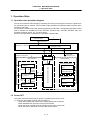
CHAPTER 2 MACHINE OPERATIONS
1. Operation State ..........................................................................................................
1.1 Operation state transition diagram.......................................................................
1.2 Power OFF ......................................................................................................
1.3 Not ready.........................................................................................................
1.4 Ready ..............................................................................................................
1.4.1 Reset.......................................................................................................
1.4.2 Automatic operation start.........................................................................
1.4.3 Automatic operation pause ......................................................................
1.4.4 Automatic operation stop.........................................................................
2. Indicator Lamps.....................................................................................................
2.1 NC unit ready...................................................................................................
2.2 Automatic operation busy .............................................................................
2.3 Automatic operation start busy ........................................................................
2.4 Automatic operation pause busy......................................................................
2.5 Return to reference point .................................................................................
2.6 NC alarm .........................................................................................................
2.7 M00 ................................................................................................................
2.8 M01 ................................................................................................................
2.9 M02/M30..........................................................................................................
II − 2
II − 2
II − 2
II − 3
II − 3
II − 3
II − 3
II − 4
II − 4
II − 5
II − 5
II − 5
II − 5
II − 5
II − 5
II − 5
II − 5
II − 6
II − 6
iii
3. Reset Switch and Emergency Stop Button .........................................................
3.1 Reset switch ....................................................................................................
3.2 Emergency stop button....................................................................................
4. Operation Mode .....................................................................................................
4.1 Mode select switch ..........................................................................................
4.2 Jog feed mode.................................................................................................
4.3 Rapid traverse mode .......................................................................................
4.4 Reference point return mode ...........................................................................
4.5 Incremental feed mode ....................................................................................
4.6 Handle feed mode ...........................................................................................
4.7 Program run mode...........................................................................................
4.8 MDI operation mode ........................................................................................
5. Operation Panel Switches in Operation Mode ....................................................
5.1 Rapid traverse override ...................................................................................
5.2 Cutting feed override .......................................................................................
5.3 Manual feedrate...............................................................................................
5.4 Handle/incremental feed magnification factor ..................................................
5.5 Handle feed axis selection ...............................................................................
5.6 Manual pulse generator ...................................................................................
5.7 Cycle start and feed hold .................................................................................
5.8 Feed axis selection ..........................................................................................
6. Operation Switch Functions and Other Functions .............................................
6.1 All axes machine lock ......................................................................................
6.2 Each axis machine lock ...................................................................................
6.3 Display lock .....................................................................................................
6.4 Miscellaneous function lock .............................................................................
6.5 Single block .....................................................................................................
6.6 Dry run.............................................................................................................
6.7 Manual override ...............................................................................................
6.8 Override cancel ...............................................................................................
6.9 Optional stop ...................................................................................................
6.10 Optional block skip ..........................................................................................
6.11 Manual absolute ..............................................................................................
6.12 Mirror image ....................................................................................................
6.13 Error defect......................................................................................................
6.14 Chamfering......................................................................................................
6.15 Follow-up function............................................................................................
6.16 Axis removal ....................................................................................................
6.17 Manual/automatic synchronous feed ...............................................................
6.18 Handle interruption ..........................................................................................
6.18.1 Outline.....................................................................................................
6.18.2 Interruptible conditions ............................................................................
6.18.3 Interruption effective axis.........................................................................
6.18.4 Axis movement speed resulting from interruption ....................................
6.18.5 Path resulting after handle interruption ....................................................
6.18.6 Handle interruption in nose R compensation ...........................................
6.18.7 Interrupt amount reset .............................................................................
6.18.8 Operation procedure................................................................................
6.19 Deceleration check ..........................................................................................
6.20 Miscellaneous command high-speed output ....................................................
6.21 Rapid traverse constant inclination acceleration/deceleration ..........................
iv
II − 7
II − 7
II − 7
II − 8
II − 8
II − 9
II − 10
II − 11
II − 13
II − 14
II − 15
II − 16
II − 17
II − 17
II − 17
II − 17
II − 18
II − 18
II − 18
II − 19
II − 19
II − 20
II − 20
II − 20
II − 20
II − 21
II − 21
II − 21
II − 21
II − 21
II − 22
II − 22
II − 23
II − 24
II − 25
II − 25
II − 25
II − 25
II − 25
II − 26
II − 26
II − 26
II − 27
II − 27
II − 28
II − 30
II − 31
II − 32
II − 33
II − 37
II − 39
CHAPTER 3 MAINTENANCE
1. Confirming the Operation .....................................................................................
1.1 Confirming the axis movement direction ..........................................................
1.2 Confirming the limit switch operation ...............................................................
2. Confirming the Drive Section ...............................................................................
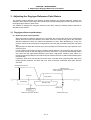
3. Adjusting the Dog-type Reference Point Return .................................................
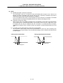
3.1 Dog-type reference point return .......................................................................
3.2 Reference point return parameters ..................................................................
3.3 Dog-type reference point return adjustment procedures..................................
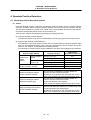
4. Absolute Position Detection .................................................................................
4.1 Absolute position detection system..................................................................
4.2 Starting up absolute position detection ............................................................
4.3 Procedures for initializing for the dog-type absolute position detection ............
4.4 Procedures for the dogless-type detection; initializing with machine end
stopper method................................................................................................
4.4.1 Random point type (Screen operation method) .......................................
4.4.2 Grid point point type (Screen operation method) .....................................
4.4.3 Random point type (automatic dogless-type)...........................................
4.4.4 Grid point point type (automatic dogless-type).........................................
4.4.5 Notes.......................................................................................................
4.5 Procedures for the dogless-type detection; initializing with marked point
alignment method ............................................................................................
4.5.1 Random point type (Screen operation method) .......................................
4.5.2 Grid point type (Screen operation method) ..............................................
4.5.3 Notes.......................................................................................................
4.6 Various settings for dogless-type absolute position detection ..........................
4.7 Absolute position detection check function ......................................................
5. Daily Maintenance ...................................................................................................
5.1 Daily inspection................................................................................................
5.1.1 Checking the external view......................................................................
5.1.2 Checking the inside of the control panel ..................................................
5.2 Replacement ...................................................................................................
5.2.1 Replacing the battery...............................................................................
5.2.2 Replacing the backlights..........................................................................
5.2.3 Replacing the cooling fan ........................................................................
5.2.4 Replacing the hard disk drive (HDD) .......................................................
5.3 Cleaning and handling .....................................................................................
5.3.1 Escutcheon..............................................................................................
5.3.2 Floppy disk ..............................................................................................
5.3.3 Hard disk drive ........................................................................................
5.3.4 LCD panel ...............................................................................................
5.3.5 PCMCIA Card..........................................................................................
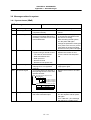
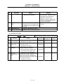
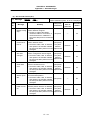
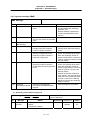
6. Fault Diagnosis and Action ....................................................................................
6.1 Checking the fault occurrence status...............................................................
6.2 Fault examples ................................................................................................
v
III − 1
III − 1
III − 1
III − 2
III − 3
III − 3
III − 5
III − 9
III − 10
III − 10
III − 12
III − 13
III − 14
III − 14
III − 15
III − 16
III − 17
III − 18
III − 19
III − 19
III − 20
III − 21
III − 22
III − 24
III − 25
III − 25
III − 25
III − 25
III − 26
III − 26
III − 28
III − 29
III − 30
III − 33
III − 33
III − 33
III − 37
III − 37
III − 38
III − 39
III − 39
III − 40
CHAPTER 4 APPENDICES
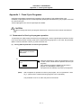
Appendix 1. Fixed Cycle Programs .......................................................................
1.1 Parameters for fixed cycle program operation .................................................
1.2 Inputting/outputting fixed cycle programs.........................................................
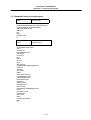
1.3 Standard fixed cycle subprogram ....................................................................
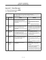
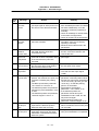
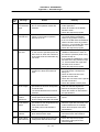
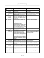
Appendix 2. Operation Messages..........................................................................
2.1 Position display-related operation messages...................................................
2.2 Operation search-related operation messages ................................................
2.3 Graphic display-related operation messages ...................................................
2.4 Compensation-related (tool compensation, coordinate system offset)
operation messages ........................................................................................
2.5 Data input/output-related operation messages ................................................
2.6 Parameter-related operation messages...........................................................
2.7 Tool-related operation messages ....................................................................
2.8 Manual tool length measurement-related operation messages .......................
2.9 Editing-related operation messages ................................................................
2.10 Diagnosis-related operation messages............................................................
2.11 Absolute position detection-related operation messages .................................
2.12 Maintenance-related operation messages .......................................................
2.13 Other operation messages ..............................................................................
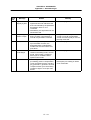
Appendix 3. Alarm Messages ..................................................................................
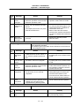
3.1 Errors during operation (M{{) .......................................................................
3.1.1 Operation Errors (M01) .............................................................................
3.1.2 Absolute position return again (M02) ........................................................
3.1.3 Interference check alarm (M03) ................................................................
3.1.4 Interference area alarm (M04) ..................................................................
3.2 Stop Codes (T{{)..........................................................................................
3.3 Messages related to servo...............................................................................
3.3.1 Servo alarms (S{{) ................................................................................
3.3.2 Servo warnings (s{{)..............................................................................
3.4 Messages related to spindle ............................................................................
3.4.1 Spindle alarms (S{{) ..............................................................................
3.4.2 Spindle warnings (s{{) ...........................................................................
3.5 MCP alarms.....................................................................................................
3.5.1 MCP alarms (Y{{) ..................................................................................
3.5.2 MCP warnings (y{{) ...............................................................................
3.6 Messages related to system ............................................................................
3.6.1 System alarms (Z{{) ..............................................................................
3.6.2 System warnings (z{{) ...........................................................................
3.7 Alarms related to user PLC (U{{) .................................................................
3.8 Program errors (P{{{) .................................................................................
vi
IV − 1
IV − 1
IV − 2
IV − 3
IV − 14
IV − 14
IV − 14
IV − 14
IV − 15
IV − 15
IV − 18
IV − 18
IV − 18
IV − 19
IV − 20
IV − 20
IV − 21
IV − 21
IV − 22
IV − 22
IV − 22
IV − 31
IV − 31
IV − 31
IV − 32
IV − 35
IV − 35
IV − 40
IV − 42
IV − 42
IV − 47
IV − 48
IV − 48
IV − 50
IV − 51
IV − 51
IV − 54
IV − 55
IV − 56
CHAPTER 1 SCREEN OPERATIONS
CHAPTER 1 SCREEN OPERATIONS
1. Operating the Setting Display Unit
1. Operating the Setting Display Unit
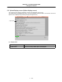
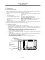
1.1 Setting display unit
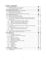
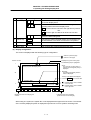
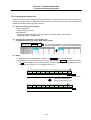
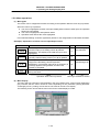
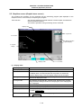
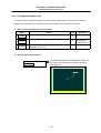
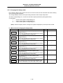
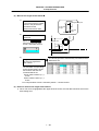
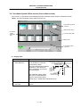
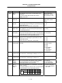
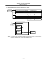
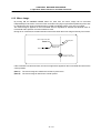
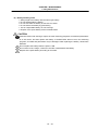
(1) Setting display unit appearance
An LCD display is used for the screen displays.
Operations such as screen transition and data setting are carried out with the NC keyboard.
The setting display unit is configured of the LCD display, various keys and menu keys as shown
below.
The drawing below shows a horizontal layout of the LCD display and NC keyboard, but these can
also be arranged vertically.
5. Data setting keys
(alphabet, numerals, symbols)
READY LED
1. Function keys
6. Window operation keys
3. Previous screen display key
(System changeover)
8. Lower case input key
LCD display
7. Data correction keys
SHIFT
RESET
13. Menu keys
12. RESET key
9. SHIFT key
INPUT
CALC
11. INPUT key
2. Page changeover key 11. Cursor keys
4. Menu changeover keys
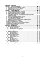
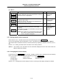
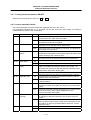
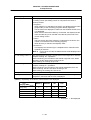
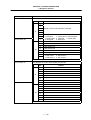
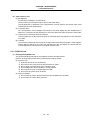
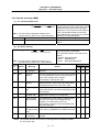
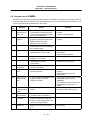
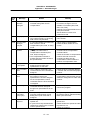
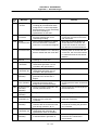
The following keys are provided on the keyboard.
Key type
1.
Function key
Key
Operation
MONITOR
This displays the menu of the screen related to
"operations". ( → Refer to "2. Monitor Screens".)
SETUP
This displays the menu of the screen related to "setup".
( → Refer to "3. Setup Screens".)
2.
Page
changeover
key
EDIT
This displays the menu of the screen related to "editing".
( → Refer to "4. Edit Screens".)
DIAGN
This displays the menu of the screen related to "diagnosis".
( → Refer to "5. Diagnosis Screens".)
MAINTE
This displays the menu of the screen related to
"maintenance". ( → Refer to "6. Maintenance Screens".)
Previous page
key
Next page key
When the displayed contents cover several pages, this
displays the contents of the previous page. The " " mark
at the top of the screen indicates that there is a previous
page.
When the displayed contents cover several pages, this
displays the contents of the next page. The " " mark at the
top of the screen indicates that there is a next page.
I–1
CHAPTER 1 SCREEN OPERATIONS
1. Operating the Setting Display Unit
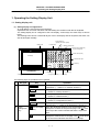
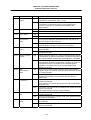
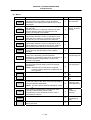
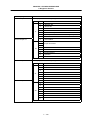
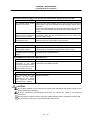
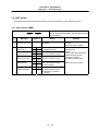
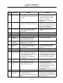
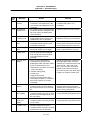
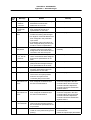
Key type
3.
Previous
screen
display key
(System
changeover)
Key
Operation
This redisplays the previously displayed screen.
BACK
Previous screen
display key
$→$
System
changeover key
4.
5.
Menu
changeover
key
Data setting
key
When using a multi-system NC, this displays the data of the
next system. The screen does not change if it is a system
common screen or when only one system is used.
(left side)
This changes the operation menu for the displayed screen
to the current screen group screen selection menu.
This is also used to cancel the menu operations of the
displayed screen.
(right side)
When all of the menus cannot be displayed at once, this
displays the menus not currently displayed.
The " " and " " marks at the bottom of the screen indicate
that there are menus not displayed.
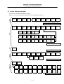
A
B
C
D
E
F
G
H
I
J
K
L
M
N
O
P
Q
R
S
T
U
V
W
X
Y
Z
0
1
2
3
4
5
6
7
8
9
+
–
=
/
.
;
These keys are pressed to set alphabetic characters,
numerals and operation symbols, etc.
etc.
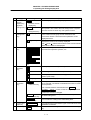
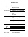
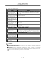
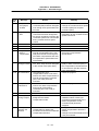
6.
Window
operation
key
This displays a window. (Not used)
This changes the active window. (Not used)
This displays the menu for selecting operations on the
window. (Not used)
? Help key
7.
Data
correction
key
INSERT
Data insert key
This displays the help. (Not used.)
This inputs the data insertion mode. When a data setting
key is pressed, a character is inserted in front of the current
cursor position.
The overwrite mode is entered when the DELETE ,
C·B ESC , INPUT , cursor or Tab, etc., keys are pressed,
or when the screen is changed.
DELETE
Data delete key
C·B ESC
This deletes the character just before the cursor position in
the data setting area.
This cancels the setting in the data setting area.
Cancel key
8.
Lower case
input key
LOWER CASE
This changes the input between upper case and lower case
alphabetic characters.
9.
SHIFT key
SHIFT
This validates the setting on the lower line of data setting
key.
I–2
CHAPTER 1 SCREEN OPERATIONS
1. Operating the Setting Display Unit
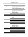
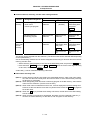
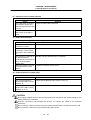
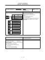
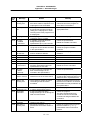
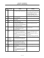
Key type
10. Cursor key
Key
↑
Operation
This moves the cursor up or down one when setting data in
the screen display items.
↓
← →
This moves the cursor one item to the left or right when
selecting data in the screen display items.
← at cursor left end : Moves to the right end of previous
line.
→ at cursor right end: Moves to left end of next line.
←
→
This moves the data input cursor one character to the left or
right in the data setting area.
11. INPUT key
INPUT
This fixes the data in the data setting area, and writes it to
the internal data. The cursor moves to the next position.
12. RESET key
RESET
This resets the NC.
13. Menu keys
This changes the screen and displays the data.
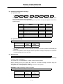
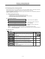
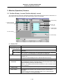
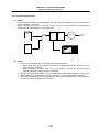
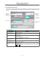
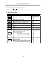
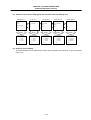
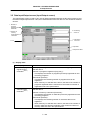
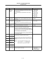
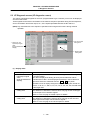
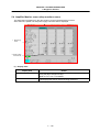
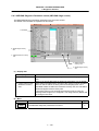
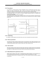
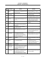
(2) Display configuration
The screen is displayed with the following type of configuration:
: There is a previous page.
: There is a next page.
Number of lines
1
Displays the type of screen group.
The selected group is highlighted.
System No. Screen name
Screen group display
Alarm :
The currently occurring alarm or
warning with the highest priority is
displayed.
General-purpose data display area
Message :
The setting and display function
status is displayed.
20
The key input details are displayed.
Press the INPUT key to fix the data.
Operation state/
Operation message
4
Operation status
Alarm/warning (one line)
: Indicates that a menu is hidden
on the left side.
: Indicates that a menu is hidden
on the right side.
Data setting area
Menu (two lines)
<
>
Displays the menu for changing the
screens.
Indicates a menu that is hidden.
(Shifts the menu to the left/right.)
When using one system, the system No. is not displayed at the upper left of the screen. The number
of the currently displayed system is displayed only when two or more systems are being used.
I–3
CHAPTER 1 SCREEN OPERATIONS
1. Operating the Setting Display Unit
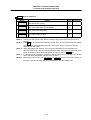
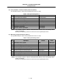
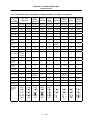
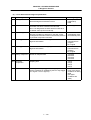
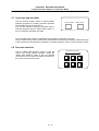
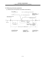
(3) Operation state/operation message
1) Operation state
1
SYN
2
SYN
3
AUT
4
BST
5
AUT
6
BST
7
BST
8
BST
The operation state indicates the currently selected operation state for each system. (The state
for up to eight systems can be displayed.)
Note that if an operation message is displayed, the operation message will appear instead of the
operation state.
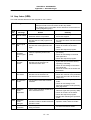
Symbol
EMG
RST
RDY
AUT
SYN
CRS
BST
HLD
Details
Emergency stop
Resetting NC
Operation READY state
In automatic operation
Waiting for synchronization
Waiting for cross conversion
Stopped
Halted
Character
color
Black
Black
Black
Black
Black
Black
Black
Black
Background
color
Red
Green
Green
Green
Green
Green
Green
Green
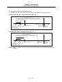
2) Operation message
E01 Setting error
Operation message
Character
color
Black
Background
color
Gray
• The operation message can be canceled by pressing any key (the operation state display will
reappear).
• Even if the operation mode changes while an operation message is displayed, the operation
message display will not be canceled.
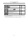
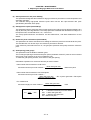
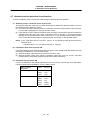
(4) Alarm/warning
$1 P232 No program No.
The number of the system in which the alarm occurred, the alarm No. and the alarm message
character string are displayed.
The system No. is not displayed for an alarm common to the systems.
When a warning occurs, the system No., alarm No. and alarm message character string are
displayed in the same manner as the alarm.
The system No. is not displayed for a warning common to the systems.
(Example) Display of warning common to system
z90 Diagnosis information acquired
Alarm
Warning
Character
color
Black
Black
Background
color
Red
Yellow
I–4
CHAPTER 1 SCREEN OPERATIONS
1. Operating the Setting Display Unit
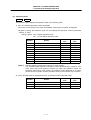
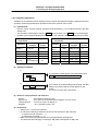
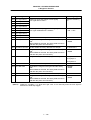
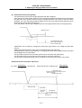
(5) Operation status
MDI
:
RUN
The operation status displays the operation state in the following order.
1) MDI: The selected operation mode is displayed.
When two or more systems are used, the operation mode of the 1st system is displayed.
Whether to display the operation mode can be selected with the Basic common parameter
"1329 sp_3" value.
1329 sp_3(bit3)
(Note 1)
OFF : Display operation mode
ON : Do not display operation mode
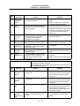
Symbol
Details
MEM
MDI
RPD
JOG
HDL
STP
MNL
ZRN
INI
Memory mode
MDI mode
Rapid traverse
Jog mode
Handle
Step
Manual random feed
Zero point return mode
Automatic dog-less zero point return
No mode
Character
color
Black
Black
Black
Black
Black
Black
Black
Black
Black
Black
Background
color
Gray
Gray
Gray
Gray
Gray
Gray
Gray
Gray
Gray
Gray
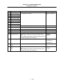
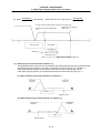
Note the following points when using two or more systems.
The operation status displays the operation mode selected for the 1st system. Thus,
when using two-or-more-systems machine for which the operation modes are
separately selected for each system, the operation mode displayed for a system
other than the 1st system, and the operation mode on the machine may not match.
2) RUN: The MDI status is displayed when the 1) operation mode is the MDI mode.
Symbol
NON
SET
RUN
Details
No MDI setting
MDI setting completed
MDI running
I–5
Character
color
Black
Black
Black
Background
color
Gray
Gray
Gray
CHAPTER 1 SCREEN OPERATIONS
1. Operating the Setting Display Unit
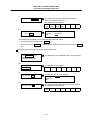
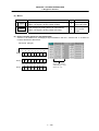
1.2 Screen transition diagram
Operation
(Monitor)
The screen is configured of operation groups.
Refer to "1.3 Screen selection procedures" for how to display the screens.
Position
Position
Position
Operation
display1
display2
display3
search
Graphics
Common
Common
Local
PLC
Control
variable 1
variable 2
variable
switch
param
→ Refer to "2. Monitor (Operation) Screens".
Tool wear
Tool data
data
Tool life
Coord
Input/
User
Machine
manage
offset
Output
parameter
parameter
Setup
I/O
Barrier
param
param
data
BaseAx
BaseSys
BaseCom
Axis
Zp-rtn
Servo
Spindle
Spindle
Spindle
param
param
param
spec
param
param
NC prm
param
typ sv
Setup
Axis
param
PLC
PLC
PLC
Bit
Custom
Macro
Posn
Er comp
Er comp
constnt
timer
counter
select
variabl
list
switch
param
data
Edit
→ Refer to "3. Setup Screens".
Edit
→ Refer to "4. Edit Screens".
Option
I/F
Amp
Alarm
config
display
diagnosis
monitor
message
Diagnosis
(Diagnos)
H/W S/W
MELDAS
diagn
Servo
Spindle
Power
unit
unit
unit
Maintenance
(Mainte)
→ Refer to "5. Diagnosis Screens".
Mainte-
PLC
nance
LADDER
Psswd
PLC
To
Option
input
stop
abs pos
setting
Format
To
To
SRAM
HMI
in/out
param
backup
quit
→ Refer to "6. Maintenance Screens".
I–6
∗
CHAPTER 1 SCREEN OPERATIONS
1. Operating the Setting Display Unit
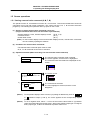
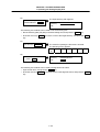
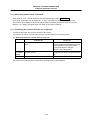
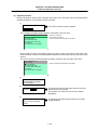
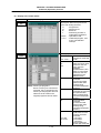
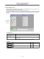
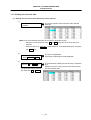
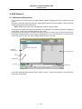
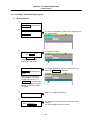
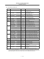
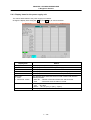
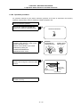
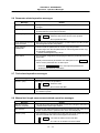
1.3 Screen selection procedures
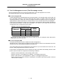
The screen is selected by pressing a function key such as MONITOR or SETUP , or by pressing a menu
key displayed in the screen selection menu.
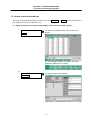
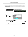
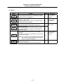
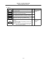
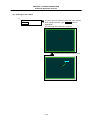
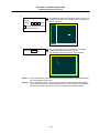
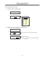
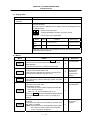
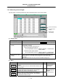
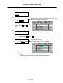
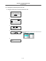
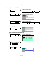
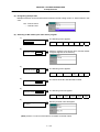
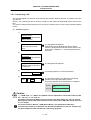
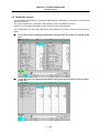
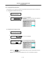
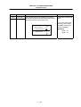
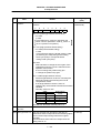
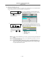
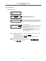
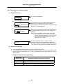
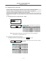
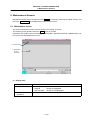
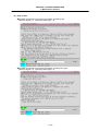
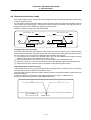
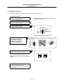
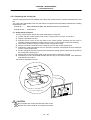
(1) Operation method (To display "Input/Output" screen from the "Setup" group)
1)
Press the function key
SETUP .
The previously displayed setup related screen will
appear.
The menu display will differ according to the Setup
parameter "Default menu" settings.
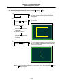
2)
Press the menu key
Input/Output .
The Input/Output screen appears.
I–7
CHAPTER 1 SCREEN OPERATIONS
1. Operating the Setting Display Unit
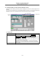
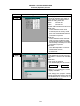
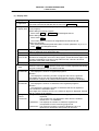
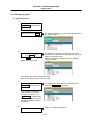
1.4 Setting data
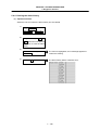
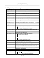
1.4.1 Setting numerals and alphabetic characters
(1) Operation method
The data is basically set with the following methods:
1) Menu selection
2) Number selection
3) Cursor movement
4) Data key input
5) INPUT key input
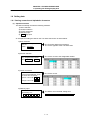
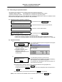
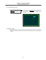
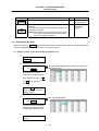
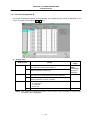
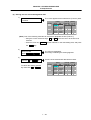
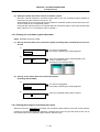
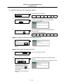
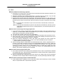
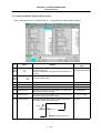
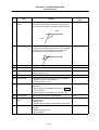
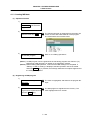
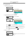
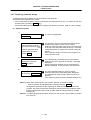
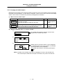
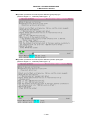
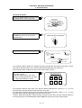
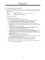
An example for setting the data on the Tool wear data screen is shown below.
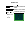
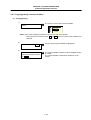
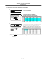
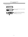
1) Menu selection
Press the menu key for the item
to be set.
Menu Tool wear
The Tool wear data screen appears.
The cursor appears at the Tool wear data.
2) Number selection
If the setting item has a number
(No.), designate that number.
The cursor moves to the designated number.
Menu Ofset No. 11 INPUT
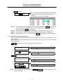
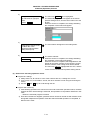
3) Cursor movement
If there is no number or when
moving up/down/left/right, move
the cursor with cursor keys.
Up/down: Move with
↑
,
The cursor moves.
↓
Left/right: Move with ← →
4) Data key input
Set data with the numeral keys or
alphabet keys, etc.
1
2
.
2
0
5
The data is set in the data setting area.
12. 205
I–8
CHAPTER 1 SCREEN OPERATIONS
1. Operating the Setting Display Unit
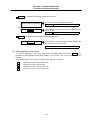
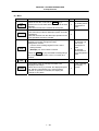
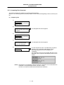
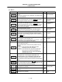
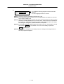
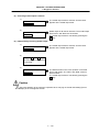
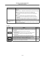
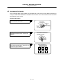
5) INPUT key input
Press the INPUT key.
(Note 1)
The contents in the data setting area are fixed, the data
setting is processed, and the results appear on the
screen.
The cursor moves to the next position.
The contents in the data setting area are only displayed until the INPUT key is pressed.
These contents are invalidated if the screen is changed. The data is written into the
memory when the INPUT key is pressed.
(Note 2)
(Note 3)
(Note 4)
Special settings may be required depending on the data type. Refer to each item.
The cursor may move to the right of the display item depending on the data type.
If an illegal key is set, an error occurs when INPUT is pressed. Reset the correct data.
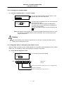
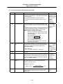
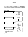
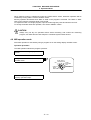
(2) Operations in the data setting area
The key is input at the position where the cursor is displayed. If a cursor is not displayed, the key
input is invalid.
When a key is input, the data appears at the cursor position, and the cursor moves one character
space to the right.
→
/
←
keys: Moves the cursor one character to the left or right.
1)
The cursor is at the position
shown on the right.
1 2 3 7 7 7 44 5 6
2)
Press the
→
The cursor moves one character space to the right.
key.
1 2 3 7 7 7 45 6
INSERT key: Enters the insert mode.
1)
Move the cursor to the position
where the data is to be inserted.
The cursor moves in the data setting area.
1 2 3 44 5 6
2)
Press the INSERT key, and
1 2 3 7 7 7 44 5 6
then the data keys.
INSERT
7
7
The data is inserted, and the cursor moves to the right.
7
(Note) The overwrite mode is entered when the DELETE , C·B ESC keys are pressed, or when the
screen is changed.
I–9
CHAPTER 1 SCREEN OPERATIONS
1. Operating the Setting Display Unit
DELETE key: Deletes the character in front of the cursor.
1)
Move the cursor to the position
where the data is to be deleted.
The cursor moves in the data setting area.
1 2 3 7 7 44 5 6
2)
Press the DELETE key.
The character in front of the cursor is deleted, and the
cursor moves.
12377456
C·B ESC key: Deletes all characters in the data setting area.
1)
Press the C·B ESC key.
All characters in the data setting area are deleted, and
the cursor moves to the left end.
(3) Cursor operations on the screen
If a cursor is displayed on the screen, data is set in the data setting area and the INPUT key is
pressed, the data appears at the cursor position on the screen. The cursor moves to the next
position.
The following keys can be used to move the cursor with the cursor keys.
↑
:
Moves the cursor to the previous line.
↓
:
:
:
Moves the cursor to the next line.
Moves the cursor one item to the left.
Moves the cursor one item to the right.
←
→
I – 10
CHAPTER 1 SCREEN OPERATIONS
1. Operating the Setting Display Unit
1.4.2 Inputting operations
In addition to the method of directly inputting numeric data for specific data settings, a method to input the
operation results using arithmetical operators and function symbols can be used.
(1) Input method
Numeric values, function symbols, operators and parentheses ( ) are combined and set in the data
setting area.
The operation results appear when the INPUT key is pressed. If the INPUT key is pressed again,
the data is processed and displayed on the screen. The contents in the data setting area are erased.
Examples of operator settings,
and results
Operation
Setting
example
Function symbols, setting examples
and results
Operation
results
Addition
=100+50
150.000
Subtraction
=100−50
Function
Absolute
value
Function
symbol
Setting
example
ABS
=ABS (50−60)
10
50.000
Square root
=SQRT (3)
1.732
Multiplication =12.3∗4
49.200
Sine
SIN
=SIN
0.5
Division
=100/3
33.333
Cosine
COS
=COS (15)
0.966
Function
=1.2∗
(2.5+SQRT(4))
Tangent
TAN
=TAN
1
Atangent
ATAN
5.4
SQRT
Operation
results
(30)
(45)
=ATAN (1.3)
0.915
(2) Operation examples
1)
Set as shown below, and press
The operation results appear in the data setting area.
the INPUT key.
240
=12∗20 INPUT
2)
The contents of the data setting area are fixed, the data
setting is processed and the results appear on the
screen.
The cursor moves to the next position.
Press the INPUT key again.
(3) Notes for using operators and functions
Division
Square root
Triangle function
Atangent
:
:
:
:
Zero division causes an error.
If the value in the parentheses is negative, an error occurs.
The unit of angle θ is degree (°).
−90 < operation results < 90.
(4) Restrictions
• Always use "=" for the first character.
• Do not use the following characters as the second character or last character.
Invalid as second character: ∗, /, )
Invalid as last character: ∗, /, (, +, • Make sure that the left parentheses and right parentheses are balanced.
• The 360° limit does not apply on the angle. SIN (500) is interpreted as SIN (140).
I – 11
CHAPTER 1 SCREEN OPERATIONS
1. Operating the Setting Display Unit
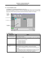
1.5 Screen operations
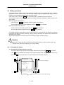
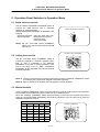
1.5.1 Setting a manual value command (S, M, T, B)
The spindle function S, miscellaneous function M, tool function T and 2nd miscellaneous function B
commands can be set with screen operations. This carries out the S, M, T, B command execution
program by commanding the operations with key inputs on the screen.
(1) Screens in which manual value commands can be set
(Target commands that can be set are shown in parentheses.)
• Position display1 screen, Position display2 screen
• Tool data screen
• Coord offset screen
(S, M, T, B)
(M, T)
(M, T)
(Note) On the Position display1 screen and Position display2 screen, manual value commands
can be issued by inputting the address.
(2) Conditions for manual value commands
• The manual value command option must be valid.
• S, M, T or B command must not be in execution.
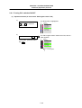
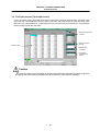
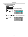
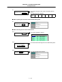
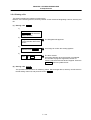
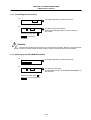
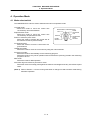
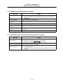
(3) Operation methods (When executing T31 with a manual value command)
1)
Select the menu
Manual value .
The manual value command mode is entered.
The cursor appears, and the menu is highlighted.
The command value executed last is displayed on the
screen.
S1 1000
S2 2000
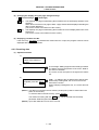
2)
Using the ↑ , ↓ keys, move
the cursor to the position to be
set. (Note 1)
3)
Set the numeric value, and press
the INPUT key.(Note 2)
1500
(Note 1)
INPUT
The cursor moves.
S1 1000
S2 2000
The command is executed.
The menu highlight is removed, and the cursor
disappears.
On the position display1 and 2 screens, by inputting an address key such as S 1 , M
or T instead of steps 1) and 2), the cursor appears at the corresponding display
(Note 2)
position.
To set a negative value, add a "−" in front of the numeric value. Refer to "(4) Manual
value command setting and output range". When using a BCD output type or unsigned
binary output type, a value converted into a positive value is set.
I – 12
CHAPTER 1 SCREEN OPERATIONS
1. Operating the Setting Display Unit
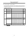
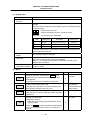
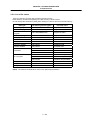
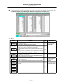
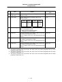
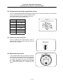
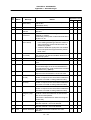
(4) Manual value command setting and output range
For the S, M, T and B commands, the type of data output from the NC unit to the user PLC is preset
to one of the following by the Machine parameters.
• BCD output
• Unsigned binary data
• Signed binary data
The following table shows the manual value command setting and output range according to the
specifications of the three types.
BCD/unsigned binary
Signed binary
S
0 to 99999999
−99999999 to 99999999
M
0 to 99999999
−99999999 to 99999999
T
0 to 99999999
−99999999 to 99999999
B
0 to 99999999
−99999999 to 99999999
(Note 1)
When using the BCD output type or unsigned binary output type, a value converted into
a positive value is output.
(Example)
(Note 2)
Setting value: M-100
Output value: M 100
If a value exceeding the setting range is set, the high-order data is dropped.
(Example)
M 1234
M 2345
Set 5
1 is dropped.
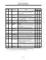
(5) Number of displayed commands
Command
S
M
T
B
(Note 1)
(Note 2)
Number of displayed commands
Follows the value set for the Machine parameter "Sfig".
(Maximum six commands)
Follows the value set for the Machine parameter "Mfig".
(Maximum four commands)
One command
One command
The S command value is displayed with the name set with the Machine parameter
"Sname".
The final command value is displayed for the S command value.
(6) Other notes
1) If the program command format is the MELDAS 600 Series standard format and a macro
interruption command code (M96, M97) or subprogram call code (M98, M99) is commanded,
the command will not be processed.
2) The manual value command mode is canceled if the following operations are carried out before
pressing the INPUT key.
• When the Manual value menu key is pressed again.
• When the
key is pressed.
• When another menu key is pressed.
• When the screen is changed.
I – 13
CHAPTER 1 SCREEN OPERATIONS
1. Operating the Setting Display Unit
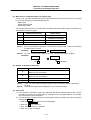
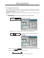
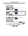
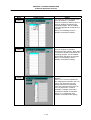
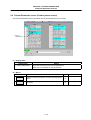
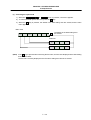
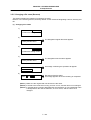
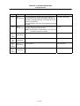
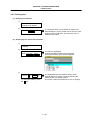
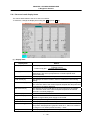
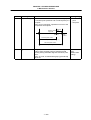
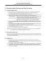
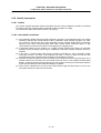
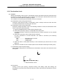
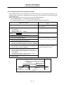
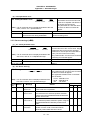
1.5.2 Changing the valid area
In screens where the display area is split, such as the Position display3 screen, Input/Output screen or
Edit screen, the area containing the screen must be validated before the display can be changed or the
data set.
The display area can be changed by pressing the menu key ( Area change ). There are screens that are
changed with the Tab keys ( ← , → ).
After changing, all operations such as data setting and cursor movement are valid in that area.
Right display area is valid.
Left display area is valid.
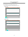
(1) To change with the menu keys.
If an Area change menu is provided, such as on the Position display3 screen or Input/Output screen,
the area is changed with the menu keys.
1) When left side of Position display3 screen is valid. (Refer to the screens above.)
Press the menu Area change .
The right area is validated.
(2) To change with Tab keys
The area is changed with the Tab keys on the Common variable (1, 2) screen, Local variable screen
and Parameter screen, etc.
I – 14
CHAPTER 1 SCREEN OPERATIONS
1. Operating the Setting Display Unit
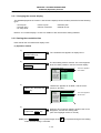
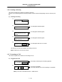
1.5.3 Changing the absolute value/incremental value setting
The mode (absolute value setting mode/incremental value setting mode) for setting the data can be
selected with the menus.
Once the mode is selected, it is saved even when the screen is changed and after the power is turned
OFF.
The absolute value setting mode is selected as the default.
(1) Screen for changing the absolute value/incremental value
• Position display3 screen (when common variables are displayed)
• Common variable (1, 2) screen
• Tool wear data screen
• Tool data screen
• Coord offset screen
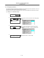
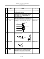
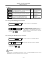
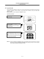
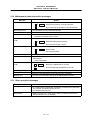
(2) Operation method
(To change the absolute value setting mode to the incremental value setting mode)
1)
The display on the screen changes to incremental
value. (Following figure.)
Settings can be made in the incremental value mode.
Press the menu Abs/Inc .
Abs /Inc
Abs / Inc
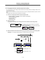
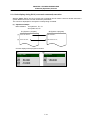
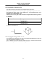
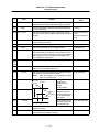
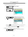
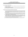
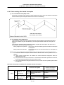
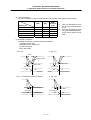
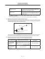
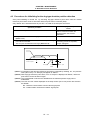
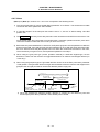
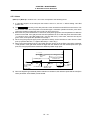
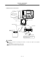
(3) Differences between the absolute value setting mode and incremental value setting mode
(Example 1) To change the G54 workpiece coordinate system as shown below.
Basic machine coordinate system
M
External offset
(EXT)
X=-150.
G54
X=-50.
G54
After changes
Before changes
G54
X1
-50.000
Y1
0.000
G54
X1 -150.000
Y1
0.000
When
Abs /Inc
, then setting value : −50
When
Abs / Inc
, then setting value : 100
I – 15
CHAPTER 1 SCREEN OPERATIONS
1. Operating the Setting Display Unit
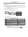
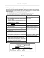
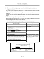
1.5.4 Changing the display axis
When axis counter or axis unit parameters are displayed on a random screen, there may be cases when
all axis information cannot be displayed because many axes are used. In this case, the remaining axis
details can be displayed by using the menu key.
(1) Screen for changing axis display
Counter display axis:
Position display1 screen
Parameter axis:
Axis param, Base axis param, Axis spec param, Z-point rtn param, Servo param,
Spindle NC param, Spindle param
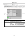
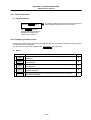
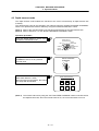
(2) Changing the Parameter screen display axis
(Changing the axis name on the Axis param screen)
1)
The axis name and data on the screen changes to the
Press the menu Next axis .
axis name and data for an axis currently not displayed.
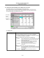
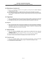
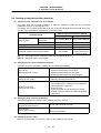
(3) Notes
1) When all axes can be displayed in a batch, the Next axis menu is not displayed.
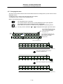
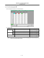
2) Depending on the screen, there may be many menus and the Next axis menu may be hidden.
mark is displayed on the upper right of the menu, change the menu by pressing the menu
If a
changeover key. (Refer to "1.5.7 Changing the menu".)
Area
change
Program
tree
Program
modal
Posn
display
Run-out
time
Common
variabl
Next
system
Local
variabl
Menu
changeover key
Menu keys
When menu changeover key is
pressed on Position display3 screen
Display
level
Abs/Inc
I – 16
Time
setting
Counter
1 type
Counter
2 type
CHAPTER 1 SCREEN OPERATIONS
1. Operating the Setting Display Unit
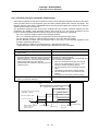
1.5.5 Selecting a device, directory and file
When using a file such as to input/output a file, carry out an operation search or edit a file, the device,
directory and target file is designated. These can be selected from the screen list.
A general explanation common for all screens is given here. Refer to the corresponding section for
details on operation for each screen.
(1) Screens requiring file selection
• Operation search screen (Select the program to be run)
• Input/Output screen (Select the machining program or other data file)
• Edit screen (Select the machining program to edit)
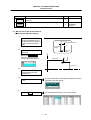
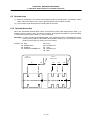
(2) File selection sequence
Designate the device where the target file is located.
→ Select from the menu. (Note 1)
↓
→ Input with a full path or select from
the list. (Note 2)
Designate the directory with a full path.
↓
→ Input the file name or select from
the list.
Designate the file name.
(Note 1)
(Note 2)
Only memory can be used for the device on the Operation search screen.
If the device is the memory, other than on the Input/Output screen, the directory does not
need to be designated.
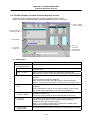
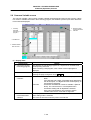
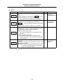
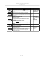
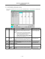
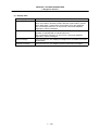
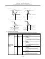
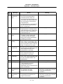
(3) Menu keys used
Main menu
Menu
Details
Type
Reference
Device
select
This displays the menu where the machining program is
stored.
If a device having a directory is selected, the directory is
set to the root.
A
Submenu
for Device
This enters the mode for inputting the directory name.
A
−
File
name
This enters the mode for inputting the file name.
A
−
List
update
This updates the list. (A list of the latest details of the
currently selected device and directory is displayed.)
C
−
From
list
Press this key to select the directory, file name or
program No.
The selection cursor appears in the list, and a random
item can be selected.
C
−
Dir
I – 17
menu.
CHAPTER 1 SCREEN OPERATIONS
1. Operating the Setting Display Unit
Device menu's submenus
Menu
Memory
RS232C
FLD
HD
(Note 1)
(Note 2)
(Note 3)
(Note 4)
(Note 5)
Details
Type
Reference
This selects the memory.
C
−
This selects RS-232C (including tape).
C
−
This selects the floppy disk.
C
−
This selects the hard disk.
C
−
The devices that can be used differ according to the screens and to the provision of
options.
If the
key is pressed when selecting the file name, the file name at the data setting
area is erased. The file already selected on the screen may or may not be erased,
depending on the screen.
When designating the directory or file name, the designated is not fixed when the
directory name or file name is just displayed at the data setting area. Confirm that these
items are displayed at the data setting area, and then press the INPUT key.
If a file other than a machining program is selected when Device:memory is set, the file
name cannot be designated. (The file name is fixed.)
Depending on the screen, the List update and From list menus may not be provided. In
this case, input the directory path and file name from the data setting area.
I – 18
CHAPTER 1 SCREEN OPERATIONS
1. Operating the Setting Display Unit
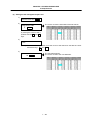
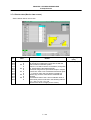
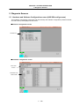
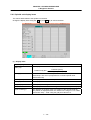
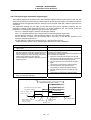
(4) Operation method
The method to select the file (program) to be operation searched on the Operate screen (example 1),
and the method for transferring the memory file to a FLD on the Input/Output screen (example 2) are
explained in this section.
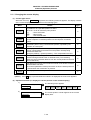
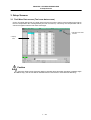
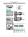
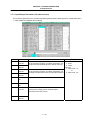
(Example 1) To select the file to be operation searched on the Operation search screen
1)
Select the Operation search
screen.
The Operation search screen appears.
The following menu appears.
NB srch
NB srch
exec
List
update
From
list
Next
system
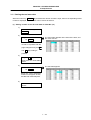
2)
Designate the file name
(program No.).
1001
The set file name appears on the screen.
INPUT
The following two methods can be used to designate the file name.
• Input the file name, and press the INPUT key.
• Press the menu key From list , move the cursor to the target file name, and press the INPUT
key.
(Note 1)
If the list contents differ from the actual device or directory, press the List update
(Note 2)
menu.
Refer to section "2.4 Operation search screen" for details on the NB search method.
I – 19
CHAPTER 1 SCREEN OPERATIONS
1. Operating the Setting Display Unit
(Example 2) To select a program file to be transferred from the memory to a FLD on the
Input/Output screen
Select the memory program file as the transfer origin.
1)
Select the Input/Output screen.
The Input/Output screen appears.
The following menu appears.
Area
change
Device
select
Dir
File
name
List
update
Trnsfr
A -> B
•••
2)
Press Area change , and
The A display area is validated.
validate the A: (transfer origin)
display area.
3)
Press the menu
Device select .
The cursor appears at "A: Device".
The following menu appears.
Memory RS232C FLD A: HD D:
4)
Press the menu Memory .
The selected device name appears.
When memory is selected, "Program" appears in the
directory as a default.
A : Device
: Memory
Directory
File
: Program
:
5)
Select the menu Dir .
The mode for inputting the directory name is entered.
(The cursor appears at "Directory:".)
The following menu appears. When selecting a device
other than the memory, refer to the procedures for
selecting the transfer destination FLD file.
From
list
Program
Param
PLC
prog
NC data
6)
Select the directory path
(program) from the menu.
The set directory path appears on the screen.
A : Device : Memory
Directory
: Program
File
:
The following two methods can be used to set the directory path.
• Set the directory path (full path) in the data setting area, and press the INPUT key.
• Press the menu key From list , move the cursor to the target directory, and press the INPUT
key.
I – 20
CHAPTER 1 SCREEN OPERATIONS
1. Operating the Setting Display Unit
7)
Press the menu File name .
The mode for inputting the file name is entered.
(The cursor appears at "File:".)
The following menu appears.
From System Param Param
list
param (Text) (Bin)
8)
Designate the file name.
1001
INPUT
A : Device
Directory
File
: Memory
: PROGRAM
: 1001
The following two methods can be used to designate the file name.
• Input the file name, and press the INPUT key.
• Press the menu key From list , move the cursor to the target file name, and press the INPUT
key.
Designate the FLD program file as the transfer destination.
9)
Press Area change , and
The B display area is validated and the cursor appears.
validate the B: (transfer
destination) display area.
10)
Press the menu
Device select .
The following menu appears.
Memory RS232C FLD A: HD D:
11)
Press the menu FLD .
The selected device name appears.
A : Device
Directory
File
: FLD A:
:
:
12)
Select the menu Dir .
The mode for inputting the directory name is entered.
The following menu appears.
From
list
I – 21
CHAPTER 1 SCREEN OPERATIONS
1. Operating the Setting Display Unit
13)
Input the directory path.
/PROGRAM/TEST INPUT
The input directory path appears.
A : Device
Directory
File
: FLD A:
: /PROGRAM/TEST
:
The following two methods can be used to set the directory path.
• Set the directory path (full path) in the data setting area, and press the INPUT key.
• Press the menu key From list , move the cursor to the target directory, and press the INPUT
key.
14)
Press the menu File name .
The mode for inputting the file name is entered.
The following menu appears.
From
list
15)
Input the file name.
precut
INPUT
A : Device
Directory
File
: FLD A:
: /PROGRAM/TEST
: precut
The following two methods can be used to designate the file name.
• Input the file name, and press the INPUT key.
• Press the menu key From list , move the cursor to the target file name, and press the INPUT
key.
I – 22
CHAPTER 1 SCREEN OPERATIONS
1. Operating the Setting Display Unit
1.5.6 Changing the display system
When using multiple systems, information such as the counter value and modals can be changed to
those for another system. Once the system is changed, the information for that system is displayed even
when the screen is changed.
The 1st system is selected when the power is turned ON.
When using a single system, and when the screen is common for all systems, the system cannot be
changed.
(1) Operation method
(To change the right area of the Position display3 screen to the 2nd system)
1)
Press the menu Area change ,
The right area is validated.
and validate the right area.
(Note) Refer to "1.5.2 Changing the valid area" for how to change the area.
2)
Press the $ → $ key.
The details displayed on the right is the 2nd system
information.
"$2" appears.
(Note 1)
By pressing the Next system menu, the system can be changed in the same manner
(Note 2)
as the $ → $ key.
The system No. changes in the following order:
$1 → $2 → $3 → ··· $n
n: Maximum No. within valid system numbers. (Maximum: $8)
I – 23
CHAPTER 1 SCREEN OPERATIONS
1. Operating the Setting Display Unit
1.5.7 Changing the menu
The menu can be used to select screens and to select functions or setting items. Up to ten menus can be
displayed at once.
To select the menu, use the menu key below the menu display.
To change the menu, use the menu changeover key.
(Refer to the following figures.)
key : The operation menu is canceled.
The screen selection menu for the currently displayed screen group appears.
The display for the currently displayed menu is highlighted.
key : When there are more than 11 menus, this key displays the remaining menus.
(Menu change)
This key can be used when "
" or " " is displayed at the upper right of the menu.
This indicates that there are more
than 11 menus, and that there are
menus following the currently
displayed menu.
Menu
display
Operate
search
To
param
Trace
ON
Erase
Program
display
Display
range
This indicates that there are more
than 11 menus, and that there are
menus before the currently
displayed menu.
Next
system
Display
mode
Menu key
Menu changeover key
Area
change
Program
tree
Program
modal
Run-out
time
Posn
display
Common Common
var-1
var-2
Next
system
Local
variabl
Menu
changeover key
Menu keys
When menu changeover key is pressed
on Position display3 screen
Display
level
Time
setting
Abs/Inc
Counter
1 type
Counter
2 type
When menu changeover key is pressed again
Area
change
Program
tree
Program
modal
Run-out
time
Posn
display
Common
var-1
Menu keys
I – 24
Common
var-2
Local
variabl
Next
system
Menu
changeover key
CHAPTER 1 SCREEN OPERATIONS
1. Operating the Setting Display Unit
1.5.8 Menu operations
(1) Menu types
The menus can be categorized as follow according to the operation after the menu key is pressed.
When the menu key is pressed:
A. The menu is highlighted, and the user input standby state is entered. After input, the operation
follows the input details.
B. The menu is highlighted, and operation starts.
C. Operation starts without the menu highlighted.
In this manual following "2. Monitor (Operation) Screens", this categorization is described as follows.
(Example) Explanation of menus used in Input/Output screen
Menu
Details
Area
change
This changes the setting area to file setting column A
(transfer origin) or file setting column B (transfer
destination). The display of the valid area (A or B) is
highlighted.
C
List
update
This updates the list. The directory list selected in the
currently valid file setting column (A or B) is updated.
C
Trnsfr
A→B
This copies the file in file setting column A (transfer
origin) to the file setting column B (transfer
destination). (The transfer origin file is not changed.) A
message appears during transfer and when the
transfer is completed.
B
Stop
This interrupts the process (transfer, compare, etc.)
during execution.
C
Operation when menu is pressed
Type
Reference
1.5.2 Changing
the valid area
3.5.2
Transferring a file
Menu type Reference section
(2) Menu display
The menu that can currently be used appears in the menu display area. A menu name displayed in
gray indicates that the menu cannot be used. Depending on the parameter (Setup parameter
"Invalid gray menu∗") setting, menus that are not used can be set not to display.
The following screen shows that the menu used for the modal display is invalid.
I – 25
CHAPTER 1 SCREEN OPERATIONS
2. Monitor (Operation) Screens
2. Monitor (Operation) Screens
2.1 Position Display 1 screen (Position display1 screen)
The counter value of each axis in automatic operation can be referred to on this screen. Furthermore, on
this screen, the counter can be set, and manual values can be commanded.
3. Speed display
1. Currently executed
machining program
4. S, M, T, B
commands
5. Actual spindle
rotation speed
2. Counter display
6. Buffer display
(1) Display items
Display item
Details
1. Currently executed
machining program
Main O 10 ···
This displays the program No., sequence No. and block No. currently being
executed.
Sub
···
When executing a subprogram, the subprogram's program No., sequence
No., block No., and subprogram's nesting level are displayed.
O 1234
2. Counter display
This displays the counter of the current position and workpiece coordinates
positions, etc.
The type of counter displayed can be selected with the menu key.
3. Speed display
The speed in the vector direction, currently being moved in, is displayed.
4. S, M, T, B
commands
This displays the command value for the S (spindle speed command value),
M (miscellaneous function command value), T (tool command value), and B
(2nd miscellaneous function command value).
Refer to "1.5.1 Setting a manual value command" for how to set the manual
value command.
5. Actual spindle
rotation speed
The actual rotation speed of the 1st spindle and 2nd spindle is displayed.
6. Buffer display
This displays the contents of the machining program currently being
executed.
The block being executed is highlighted. Refer to "2.2.3 Correcting the
buffer" for details on correcting the buffer.
I – 26
CHAPTER 1 SCREEN OPERATIONS
2. Monitor (Operation) Screens
(2) Menus
Menu
Details
Counter
type
This displays the submenu for changing the display
counter. At this time, the same menu as the currently
selected counter is highlighted.
Manual
value
Random values can be input in each data item of S, M,
T and B on the screen.
When the numeric value is input, the selected S, M, T
and B functions are executed.
A
Counter
set
This presets the counter.
The current position counter value is set to "0".
A
This sets the origin.
The coordinate system is shifted so that the current
position becomes the zero point of the workpiece
coordinate system.
C
Origin
set
Type
B
system
This appears when there are two or more valid
systems.
The system No. will be incremented by one each time
this menu is pressed.
(Note) If the system No. to be displayed next exceeds
the number of valid systems, the information
for the 1st system will appear.
C
Bklight
OFF
This turns off the entire screen to prevent deterioration
of the LCD screen, etc.
The screen reappears when any key is pressed.
C
Next
I – 27
Reference
2.1.1 Changing
the counter
display
1.5.1 Setting a
manual value
command
2.1.3 Presetting
the counter
1.5.6 Changing
the display
system
−
CHAPTER 1 SCREEN OPERATIONS
2. Monitor (Operation) Screens
2.1.1 Changing the counter display
(1) Counter type menus
When the menu key Counter type is pressed, the following submenu appears. The display contents
of the counter display can be selected from the following types.
Menu
Details
Type
Currnt
posn
This displays the currently executed position and the status symbol when
the position is at a specified position or status.
#1 to #4 : 1st to 4th reference point position
] [
: Servo OFF state
MR
: Mirror image
><
: Axis removal state
C
Work
co posn
This displays the G54 to G59 workpiece coordinate system modal Nos.
and the workpiece coordinate position in that workpiece coordinate
system.
C
Machine
posn
This displays the coordinate value of each axis in the basic machine
coordinate system having a characteristic position, specified by the
machine, as a zero point.
C
Program
posn
This displays the value obtained by subtracting the tool compensation
amount compensated for that axis from the position actually being
executed for each axis.
[Program position] = [Current position] – Tool compensation amount
C
Remain
command
This displays the remaining distance of the movement command being
executed during automatic start or automatic halt. (The remaining
distance is the incremental distance from the current position to the end
point of that block.)
C
Manual
int amt
This displays the amount moved with the manual mode while the manual
absolute switch was OFF.
If the Control parameter "Interrupt amt reset" is ON, the interrupt amount
is cleared when the reset button is pressed.
C
Er comp
This displays the error compensation amount.
amnt
(Note 1)
If the
C
key is pressed while the submenu is displayed, the main menu appears.
(2) Operation methods (To display the current position in the counter display.)
1)
Press the menu key
Counter type .
The following menu appears.
Press the menu key
Currnt posn .
The current position counter appears in the counter
display area.
Currnt
posn
Work Machine Program Remain Manual
co posn posn
posn command int amt
•••
2)
I – 28
CHAPTER 1 SCREEN OPERATIONS
2. Monitor (Operation) Screens
2.1.2 Executing manual value commands
Each value for S, M, T and B can be set and executed using the menu Manual value .
Up to six S commands, four M commands, or one T command or one B command can be set.
The manual value command can be set and executed by inputting an address such as S, M or T.
Refer to "1.5.1 Setting a manual value command" for the setting method.
2.1.3 Presetting the counter (Counter set, origin set)
Counter set and origin set can be executed on this screen.
The counter set can be executed only when the counter display is the current position.
(1) Differences between counter set and origin set
Counter set
Origin set
Function
The current position counter is cleared to The coordinate system is shifted so the
zero.
current position becomes the zero point
of the workpiece coordinate system.
This is equivalent to "G92 X0".
(When X is the target axis.)
Changes in
the counter
display
"0" is displayed only for the current
position counter.
Offset
−
The current position counter and
workpiece coordinate counters become
"0".
The G92 shift amount is updated.
The counter set mode can also be entered by inputting the axis name address.
I – 29
CHAPTER 1 SCREEN OPERATIONS
2. Monitor (Operation) Screens
(2) Basic operation methods
1)
Display the current position
counter in the counter display
area.
2)
Press the menu key
Counter set .
The cursor appears at the 1st axis of the current
position counter.
POSITION
X1
Y1
Z1
Instead of pressing
Counter set , the axis name
address key can be pressed
to set the counter.
(Example) Z 1 INPUT
123.435#1
62.735 #1
804.017#1
POSITION
X1
123.435#1
Y1
62.735 #1
Z1
804.017#1
The cursor appears at the 1st axis.
The cursor appears at the designated
axis.
3)
Press the INPUT key.
"0.000" appears at the cursor position.
POSITION
0.000 #1
62.735 #1
804.017 #1
X1
Y1
Z1
"0" is displayed. The cursor will move to
the next axis.
4)
Repeat step 3) for each axis.
When the counter for the final axis has been set, the Counter set mode is canceled. The mode
can also be quit by pressing the other menu key or by pressing the Counter set menu key again.
(Note 1)
(Note 2)
(Note 3)
To set a value for an axis that is not displayed, press the menu key Next axis to
display the target axis, or input the address name of that axis.
For axes that are not to be operated, press the ↓ key and move the cursor.
When setting the origin, carry out the following operations instead of steps 2) and
3) in the operation above.
Press the menu key Origin set and INPUT .
I – 30
CHAPTER 1 SCREEN OPERATIONS
2. Monitor (Operation) Screens
2.1.4 Axis display during G110 (cross axis command) execution
With the M600L Series, the G110 (cross axis command) can be used to control a random axis with a
system different from the one that set with the parameters.
The counter is displayed for the system currently being controlled.
(1) Operation example
Basic definition
1st system X1, Z1, C1
2nd system X2, Z2
$1 (System 1 program)
$2 (System 2 program)
(1)
G110 X1 Z2 C1 ;
G110 X2 Z1 ;
(2)
G110 X1 Z2 ;
G110 X2 Z1 C1;
Counter display before program execution
($1)
POSITION
X1 100.000
Z1 50.000
C1 -10.000
($2)
POSITION
X2 200.000
Z2 150.000
I – 31
CHAPTER 1 SCREEN OPERATIONS
2. Monitor (Operation) Screens
1) Counter display after Z1 axis and Z2 axis systems are interchanged
($1)
($2)
POSITION
X1 100.000
Z1 50.000
C1 -10.000
POSITION
X2 200.000
Z2 150.000
2) Counter display after C1 axis system is changed
($1)
($2)
POSITION
POSITION
X1 100.000
Z2 150.000
X2 200.000
Z1 50.000
C1 -10.000
(Note 1)
(Note 2)
(Note 3)
If an axis not controlled by any system (free axis) is found during the random axis change
command, that axis will be counted and displayed with the system set in the parameters.
The free axis is shown with black characters and a yellow background.
If the current position simultaneous display is validated, the axis designated with the
parameters will appear. The axis displayed with the counter following the cross axis
command or random axis exchange command will not change.
I – 32
CHAPTER 1 SCREEN OPERATIONS
2. Monitor (Operation) Screens
2.2 Position Display 2 screen (Position display2 screen)
Various information regarding automatic operation is displayed on this screen.
Buffer corrections and manual value commands (SMTB) are made on this screen.
4. Counter 1 display
Counter 2 display
1. Currently executed
machining program
2. Buffer display
5. S, M, T, B
commands
3. Load meter
display area
6. Actual spindle
rotation speed
(1) Display items
Display item
Details
1. Currently executed
machining program
Main O 10···
This displays the program No., sequence No. and block No. currently
being executed.
Sub
When executing a subprogram, the subprogram's program No.,
sequence No., block No., and subprogram's nesting level are displayed.
O 1234···
2. Buffer display
This displays the contents of the machining program currently being
executed.
The block being executed is highlighted.
While correcting the buffer, the work area for corrections appears.
Refer to "2.2.3 Correcting the buffer" for details on correcting the buffer.
3. Load meter display
area
Using the user PLC, the spindle load and Z axis load, etc., is displayed as
bar graphs.
(If not created with the user PLC, this does not appear on the screen.)
This function differs depending on the machine manufacturer.
4. Counter 1 display
Counter 2 display
This displays the counter of the current position and workpiece
coordinates positions, etc.
The type of counter displayed can be selected with the menu key.
5. S, M, T, B
commands
This displays the S (spindle speed command value), M (miscellaneous
function command value), T (tool command value) and B (2nd
miscellaneous function command value).
Refer to "1.5.1 Setting a manual value command" for details on the
manual value command setting method.
6. Actual spindle
rotation speed
The actual rotation speed of the 1st spindle and 2nd spindle is displayed.
I – 33
CHAPTER 1 SCREEN OPERATIONS
2. Monitor (Operation) Screens
(2) Menus
Menu
Details
Counter
1 type
This displays the submenu for changing the display
counter. At this time, the same menu as the currently
selected counter is highlighted.
Counter
2 type
Manual
value
Buffer
correct
Next
system
Type
Random values can be input in each data item of S, M,
T and B on the screen.
When the numeric value is input, the selected S, M, T
and B functions are executed.
This enters the buffer correction mode.
This appears when there are two or more valid
systems.
The system No. will be incremented by one each time
this menu is pressed.
(Note) If the system No. to be displayed next exceeds
the number of valid systems, the information
for the 1st system will appear.
C
A
B
Reference
2.1.1 Changing
the counter
display
1.5.1 Setting a
manual value
command
2.2.3 Correcting
the buffer
1.5.6 Changing
the display
system
C
2.2.1 Setting manual value commands
Each value for S, M, T and B can be set and executed using the menu Manual value .
Up to six S commands, four M commands, or one T command or B command can be set. (Note 1)
The manual value command can also be set and executed by inputting an address such as S, M or T,
etc.
Refer to "1.5.1 Setting a manual value command" for the setting method.
(Note 1)
The number of S commands and M commands displayed and the axis name follow the
Machine parameter settings.
2.2.2 Changing the counter display
By pressing menu Counter 1 type , the counter 1 display contents can be selected from the following
types. For counter 2, the contents can be selected by pressing Counter 2 type .
• Currnt posn
• Program posn
• Er comp amnt
• Work co posn
• Remain command
• Machine posn
• Manual int amt
Refer to "2.1.1 Changing the counter display" for each counter type and display changeover method.
I – 34
CHAPTER 1 SCREEN OPERATIONS
2. Monitor (Operation) Screens
2.2.3 Correcting the buffer
(1) Outline
During automatic operation or MDI operation, a block stop can be applied, and the next command
can be corrected or changed.
When a program error occurs, the block in which the error occurred can be corrected without
resetting the NC, and operation can be continued.
Memory
Pre-read
block
Execution
block
NC operation
Machine
control
MDI
Buffer correction
(2) Details
1) The next command can be corrected in the following two cases.
• When single block stop is applied, and there is a machining program containing a next
command to be corrected.
• During automatic operation, there is an error (program error) in the next command's
machining program, and the program is stopped.
2) During memory or MDI operation, not only the displayed buffer data but also the memory and
MDI contents are corrected with the buffer corrections. (The corrected data is reflected.)
3) Several blocks following the next command can be corrected simultaneously. (Note that this is
limited to the range displayed on the screen.)
I – 35
CHAPTER 1 SCREEN OPERATIONS
2. Monitor (Operation) Screens
(3) Operation method
During a single block stop or when a program error stop occurs, the buffer can be corrected with the
following operations, and operation can be continued.
1)
Press the menu
Buffer correct .
The buffer correction mode is entered.
The normally executed program appears in the buffer correction area.
N121 G28 X10.Y10.;
N122 T1212;
N123 S1230 M3;
N124 G00 X68. Z201.;
N125 G01 X80. Z195. F50;
N126 Z150.;
N127 G02 X100. Z185. R20;
← Previous command
← Command in execution
← Next command and subsequent commands
During buffer correction, the display changes so that the next command is at the head of the
area. The buffer correction area becomes the valid area, and the keys can be input or the cursor
moved.
The cursor can be moved freely within the buffer correction area using the cursor keys.
N121 G28 X10.Y10.;
N122 T1212;
N123 S1230 M3;
N124 G00 X68. Z201.;
N125 G01 X80. Z195. F50;
N126 Z150.;
N127 G02 X100. Z185. R20;
← Next command and subsequent commands
2)
Correct the program with the
same method as editing a
normal program.
3)
Press the INPUT key.
The buffer correction mode ends, and the corrected
data is written into program.
If a program error has occurred, the error display
disappears.
4)
Confirm that the corrected
data is correct, and then
restart.
The program execution resumes from the currently
stopped position.
I – 36
CHAPTER 1 SCREEN OPERATIONS
2. Monitor (Operation) Screens
(4) Notes
Starting and ending buffer corrections
1) If automatic operation is started or there is no next command data, the buffer correction
mode is not entered even if the menu key is pressed.
2) If an "Pre-read block error" occurs and the buffer correction mode is entered, the block in
which the error occurred displays at the head of the area.
3) To stop or to cancel the buffer corrections, press the Buffer correct key again, or press the
key.
4) If another menu key, etc., is pressed before pressing the INPUT key, the corrected buffer
contents return to the original data.
5) If another screen is changed to or if the NC is reset during buffer correction, the buffer
correction is canceled. In this case, the corrected contents are not saved, and the buffer
correction mode ends.
Display data during buffer correction
1) The key operations used for corrections in the buffer correction mode are the same as the
operations when editing a program. However, blocks not displayed in the buffer correction
area cannot be displayed or edited.
2) The number of characters that can be input at once is the total of the number of characters
incremented (or decremented) through the buffer correction and the number of characters
in the other blocks displayed in the correction area. The number is a max. 234 characters
(39 characters × six lines). Therefore, if adding data, when there is no open area left in the
correction area, further characters cannot be input.
By pressing the INPUT key again at this time, the program is redisplayed for each block.
Enter the buffer correction mode again, and then add the data.
Operations during buffer correction
1) If there is no ";" (EOB) at the data in the last block corrected when the INPUT key is
pressed, it is added automatically.
2) When the buffer correction mode is entered, the last block displayed in the buffer correction
area may not fit in if the block is long, etc.
To correct this type of block, take care to the following points.
(a) If a ";" (EOB) is added to the end of the displayed data, the section following the
incomplete display becomes another block. If ";" (EOB) is not added, the following
section stays the same, and is handled as the continuation of the displayed section.
(b) If one block is deleted by pressing the C·B ESC key, the block is deleted up to the
section following the incomplete display (up to the ";").
3) Operation cannot be started during buffer correction. An alarm occurs.
2.2.4 Changing the display axis
If many axes are being used and all axes cannot be displayed on the counter at once, the menu key
Next axis can be pressed to change the displayed axes and display the remaining axes.
Refer to "1.5.4 Changing the display axis" for details.
I – 37
CHAPTER 1 SCREEN OPERATIONS
2. Monitor (Operation) Screens
2.3 Position Display 3 screen (Position display3 screen)
Various information regarding automatic operation is displayed on this screen, and the program can be
checked.
This screen has two display area, and the displayed details and system can be randomly selected and
displayed from the menu. The selected screen is held even when the screen is changed.
3. System display
2. Display area 2
1. Display
area 1
(1) Display items
Display item
Details
1. Display area 1
The display can be randomly selected from the Program tree ,
2. Display area 2
Program modal , Run-out time , Posn display , Common var-1 ,
Common var-2 or Local variabl menus. The system can be selected for
each area.
When changing the display details or system, select display area 1 or 2,
and validate the area before starting.
In the above screen, the display area 1: 1st system position display,
display area 2: 1st system modal display are selected, and the display
area 2 is valid.
3. System display
This displays the currently selected system.
I – 38
CHAPTER 1 SCREEN OPERATIONS
2. Monitor (Operation) Screens
(2) Menus
Menu
Details
Area
change
This changes between display area 1 and display area 2.
Program
tree
The display area 1 and 2 display details are selected from
these menus.
Type
C
Reference
1.5.2 Changing
the valid area
(3) Display area 1
and 2 details
Program
modal
Run-out
time
Posn
display
C
Common
var-1
Common
var-2
Local
variabl
Counter
1 type
Counter
2 type
Next
system
The counter type displayed when Posn display is selected
is selected from the menu.
The display details and selection method are the same as
the Position display1 screen and Position display2 screen.
This appears when there are two or more valid systems.
The system No. will be incremented by one each time this
menu is pressed.
(Note) If the system No. to be displayed next exceeds the
number of valid systems, the information for the 1st
system will appear.
C
1.5.6 Changing
the display system
C
2.6.2 Setting
common variables
A random variable No. can be selected when
Common var-1 , Common var-2 or Local variabl is selected.
Variabl
No.
When the variable No. is set and the INPUT key is pressed,
2.1.1 Changing
the counter
display
A
2.7.1 Displaying
local variables
the variables appear with that variable No. at the head.
The cursor moves to the details of that variable No.
2.7.1 Displaying
local variables
The display level can be selected when Local variabl is
Display
level
selected.
When the level (0 to 4) to be displayed is set and the INPUT
A
key is pressed, the local variables appear from the head of
that level.
The cursor appears at the head variable No.
Abs/Inc
The absolute value/incremental value setting mode can be
changed when Common var-1 or Common var-2 is
selected.
The "Abs/Inc" on the screen changes from incremental to
absolute, or from absolute to incremental.
Time
setting
The cumulative time can be set when Run-out time is
selected.
C
A
1.5.3 Changing
the absolute
value/incremental
value setting
2.3.2 Setting the
cumulative time
(Note) The Common var-2 menu cannot be selected when type C (450 sets) or type D (900 sets) is
selected for the number of common variable sets.
I – 39
CHAPTER 1 SCREEN OPERATIONS
2. Monitor (Operation) Screens
(3) Display area 1 and 2 details
Menu
Display details
Program
tree
Details
This displays the main program,
subprogram, MDI interrupt and user
macro call nesting structure.
O
: Program No.
N
: Sequence No.
B
: Block No.
L
: Remaining number of
subprogram repetitions
Mode : Operation mode
1 to 8 : Called subprogram, user
macro call and MDI
interrupt
This displays each modal state.
Program
modal
G01...G98
G97...G13.1
TX:
TZ:
T:
FA:
(Note) Fixed cycle programs
When a Fixed cycle command is
executed, the G command in the
Fixed cycle subprogram does not
influence the G modal in the
original program that was called.
FS:
FE:
S1 to S6
M1 to M4
T
B
I – 40
Status of currently
executed G command
modal
The X axis, Z axis tool
length and wear offset
amount for the tool
being used are
displayed.
T indicates the tool
length or wear offset
amount for the axis
selected from the
additional axes.
The program
command
asynchronous feed
speed modal value
currently being
executed is displayed.
(mm/min)
The program
command synchronous
feed speed modal
value currently being
executed is displayed.
(mm/rev)
The thread lead
command
synchronous feed
speed modal value
currently being
executed is displayed.
(mm/rev)
Program command
modal value of each
currently executed
command
S command
M command
T command
2nd miscellaneous
function (B) command
CHAPTER 1 SCREEN OPERATIONS
2. Monitor (Operation) Screens
Menu
Display details
Details
This displays the total cumulative time
in each NC operation state. Refer to
"2.3.2 Setting the cumulative time" for
details on setting each data.
Date
: Current date
Time
: Current time
Power ON : Total time from NC power
ON to OFF
Auto oper:
Total cumulative time of each
machining time in memory mode
from when automatic start button is
pressed to M02/M30 or to when
reset button is pressed.
Auto strt:
Total cumulative time of automatic
start in memory mode from when
automatic start button is pressed to
feed hold stop, block stop or to when
reset button is pressed.
Ext time:
This differs depending on the user
PLC. Refer to the instruction manual
issued by the machine
manufacturer.
Upper line:
This displays the currently executed
program No., sequence No. and block
No.
Middle line:
The counter is displayed.
The details displayed in the counter 1
and 2 can be selected from the menu
Counter 1 type and Counter 2 type
Run-out
time
Posn
display
submenus.
Refer to "2.1.1 Changing the counter
display" for details.
Lower line:
This displays the program currently
being executed in the buffer. Note that
the buffer must be corrected on the
Position display2 screen.
I – 41
CHAPTER 1 SCREEN OPERATIONS
2. Monitor (Operation) Screens
Menu
Display details
Details
Common
var-1
This displays or sets the details of the
common variables 1 (variables
common to systems). When there is a
common variable command in the
machining program, the set variable
(comment) appears when that block is
executed.
Refer to "2.6.2 Setting common
variables" for details on setting.
Common
var-2
This displays or sets the details of the
common variables 2 (variables
independent each system). When there
is a common variable command in the
machining program, the set variable
appears when that block is executed.
Refer to "2.6.2 Setting common
variables" for details on setting.
This displays the details of the local
variables.
There are 1 to 32 local variables for
each subprogram call level in the user
macros. For each level, 32 local
variable data items are displayed.
These are configured from level 0 to
level 4 in page order. If a block
containing a variable command is
executed, the details are rewritten.
Refer to "2.7.1 Displaying local
variables" for details on the display.
Local
variabl
I – 42
CHAPTER 1 SCREEN OPERATIONS
2. Monitor (Operation) Screens
2.3.1 Changing the counter display
The details displayed in the counter 1 and counter 2 displays can be randomly selected from the following
types.
• Currnt posn
• Program posn
• Er comp amnt
• Work co posn
• Remain command
• Machine posn
• Manual int amt
Refer to "2.1 Position Display 1 screen" for details on each item and the setting methods.
2.3.2 Setting the cumulative time
Each data for the cumulative time display is set.
(1) Operation method
1)
Select display area 1, and
press the menu key
Run-out time .
The cumulative time appears in display area 1.
Press the menu key
Time setting .
The time setting mode is entered. The cursor appears
at the "#1 Date" position in the Run-out time display.
2)
Run-out time display
#1 Date
1999.01.23
2 Time
12:34:56
3 Power ON 1234:59:59
4 Auto oper
5 Auto strt
6 Ext time1
7 Ext time2
The cursor appears
at "#1 Date".
1234:59:59
1234:59:59
1234:59:59
1234:59:59
3)
Set the current date (ex.;
"1999.07.03"), and press the
INPUT key.
"1999.07.03" appears at "#1 Date", and the cursor
moves to "#2 Time".
Run-out time display
#1 Date
1999.07.03
2 Time
12:34:56
3 Power ON 1234:59:59
4 Auto oper
1234:59:59
5 Auto strt
1234:59:59
6 Ext time1
1234:59:59
7 Ext time2
1234:59:59
The cursor appears
at "#2 Time".
4)
Set the data for each item,
and press the INPUT key.
When the "#7 Ext time2" setting is finished, the cursor
disappears, and the time setting ends.
(The menu highlight returns to normal.)
(Note) If the Time setting menu is pressed again or the
mode, the time setting is canceled.
I – 43
key is pressed during the time setting
CHAPTER 1 SCREEN OPERATIONS
2. Monitor (Operation) Screens
2.4 Operation Search screen
In this screen, the program (program No.) to be automatically run, the program start position (sequence
No., block No.) can be designated, and the program can be called out from the storage place such as the
memory.
1. Device and
directory after
search
4. Device name
and directory
setting columns
2. Search position
5. Search position
setting columns
3. Buffer display
6. List of directories
and files
(1) Display items
Display item
Details
1. Device and directory
after search
This displays the device and directory where the searched machining
program is located.
2. Search position
This displays the searched program position (program No., sequence
No., block No.).
3. Buffer display
This displays the contents of the currently executed or searched
machining program.
The block being executed is highlighted.
4. Device name and
directory setting
columns
This displays the device name and directory designated when the
program was selected.
5. Search position
setting columns
This sets the program No. (O), sequence No. (N) and block No. (B) of the
program to be searched.
6. List of directories and This displays a list of the contents contained in the device or directory
files
displayed at item 4.
To update the list contents, press the menu key. To scroll the list, use the
and
keys.
I – 44
CHAPTER 1 SCREEN OPERATIONS
2. Monitor (Operation) Screens
(2) Menus
Menu
Details
Type
NB srch
The mode changes to the sequence No. (N) and block
No. (B) input mode.
A
exec
The operation search is executed based on the input
sequence No. (N) and block No. (B). When the search
is completed, these Nos. are cleared.
C
List
update
This updates the list contents. (The latest contents of
the currently selected device and directory are listed.)
C
From
list
Press this key to select the directory, file name or
program No. from the list. The selection cursor
appears in the list, and a random item can be selected.
C
NB srch
Next
system
This appears when there are two or more valid
systems.
The system No. will be incremented by one each time
this menu is pressed.
(Note) If the system No. to be displayed next exceeds
the number of valid systems, the information
for the 1st system will appear.
I – 45
Reference
2.4.1 Executing
an operation
search
1.5.6 Changing
the display
system
C
CHAPTER 1 SCREEN OPERATIONS
2. Monitor (Operation) Screens
2.4.1 Executing an operation search
The following two methods can be used to search the machining program.
• System common search
: The program No. is searched for by the entire system.
• System independent search : The program No. is searched for by each system.
Which search method to use can be selected with the Machine parameters. Refer to the M600L Series
Parameter Manual (BNP-B2233) for details on the parameters.
(1) Operation search operation sequence
Select system to carry out operation
search.
↓
→ Press the menu key Next system . (Note)
Search the machining programs.
→ Input the file name or select from the file list.
↓
Designate the sequence No. and block
No.
→ Input No. in the N and B areas.
↓
Execute operation search.
→ Press the menu key NB srch exec .
(Note) The system must be selected in the following cases:
• When the machining programs are searched with the system independent search.
• When the machining programs are searched with designated sequence No. or block No.
(2) Operation method
1)
Select the system to run.
Menu Next system
The currently selected system will appear at the upper
left of the screen.
For system independent search:
Select the system in which to
execute the search.
For system common search:
Select the system for
designating the sequence No.
and block No.
2)
Input the program No.
(Example)
1001 INPUT
The designated program is searched for.
When the search is completed, a message indicating
the completion of the search will appear.
The program No. will appear at the search position on
the left side of the screen.
The following two methods can be used to designate the file name (program No.):
• Set the file name, and press the INPUT key.
• Press the menu key From list , move the cursor to the target file name, and press the
INPUT key.
With either method, the search will start when the INPUT key is pressed.
(Note) If the contents of the list differ from the actual contents, press the From list menu.
I – 46
CHAPTER 1 SCREEN OPERATIONS
2. Monitor (Operation) Screens
3)
Change to the sequence No.
(N) and block No. (B) input
mode.
Menu NB srch
The menu key NB srch will be highlighted.
Designate the sequence No.
and block No. in the
respective search position
setting areas (N, B).
The set numbers will appear in the setting areas.
Press the menu key
NB srch exec .
The search will start.
When the search is completed, a message indicating
the completion of the search will appear.
When the search is completed, the designated No. will
appear at the search position on the left of the screen,
and the contents of the setting areas will be cleared.
The menu key NB srch highlight will turn OFF, and the
The searched program No. will appear in the search
position setting area O, and the cursor will move to the
N area.
When the search is completed, a message indicating
the completion of the search will appear.
4)
5)
cursor will move to the search position setting area O.
(3) Notes when executing operation search
Program No. settings
1) Always set the O, N or B No. If none of the numbers are set, a setting error occurs.
2) If one or two of O, N and B Nos. are set, the other numbers not set are ignored during the
search.
and
keys to scroll through the list.
3) Use the
Program after searching
1) If the following operations are carried out on the edit screen after operation search, the state
changes to that in which nothing is searched, and operation is not possible. Research in this
case.
• When the searched program is erased
2) Even when the block is stopped, operation search cannot be carried out with another mode
during MDI multiple block operation. Start the search after MDI operation is completed, or
after the NC is reset.
I – 47
CHAPTER 1 SCREEN OPERATIONS
2. Monitor (Operation) Screens
2.5 Graphics screen (Graphic trace screen)
The machine tool operation can be monitored and the machining program path displayed on the
Graphics screen. This is handy for inspecting the program.
Trace function
: This function displays the actual machine movement path, and draws the
actual machine movement.
The machine operation during machining can be monitored.
1. Display area
4. Program No.
2. Tool mark
5. Machine position
6. Speed display
3. Program
display
8. Scale
7. Display mode
(1) Display items
Display item
Details
1. Display area
This is the area for drawing the tool path during the trace.
2. Tool mark
This indicates the tool position during the trace. If this mark is not within
the display area, it is assumed that the tool position is outside the
screen's display range. Thus, the display range must be changed.
3. Program display
This displays the machining program being drawn. The block being
executed is displayed in blue.
4. Program No.
This displays the program No., sequence No. and block No. currently
being executed. During execution of a subprogram, each subprogram
No. is displayed.
5. Machine position
The machine position is displayed.
6. Speed display
The feedrate (FC) is displayed.
7. Display mode
This displays the plane to be displayed. The plane can be selected with
the menu Display mode .
8. Scale
This displays the scale of the display range. The scale value can be set
with Display range .
I – 48
CHAPTER 1 SCREEN OPERATIONS
2. Monitor (Operation) Screens
2.5.1 Tracing and displaying the machine position
Press the menu key Trace ON when selecting the trace mode.
During the trace mode, the path of the machine by actual automatic operation or manual operation is
constantly drawn.
(1) Menus used in trace display
Menu
Details
Operate
search
This changes the screen to Operation search screen.
Type
Reference
C
2.4 Operation
Search screen
To
param
This changes the screen to the Parameter screen.
The parameters used on the Graphic trace screen can
be set on the Setup param screen.
C
3.7 User
parameter details
Trace
ON
This enters the trace mode. If there is a program
currently running, the path of the machine position is
traced and displayed from the current position.
B
–
Erase
This erases the figure displayed with graphics.
C
–
Program
display
This displays the machining program being drawn on
the screen.
C
–
Display
range
This changes the display scale and the display
position. The changes are selected from the menu.
The graphics displayed on the screen are erased.
A
2.5.2 Changing
the display range
Display
mode
The plane and system to be displayed are changed.
The axes corresponding to X, Y and Z are set with the
plane parameters (Setup parameters).
• Parameter (8001 to 8003)
I ... Axis for each system corresponding to X
J ... Axis for each system corresponding to Y
K ... Axis for each system corresponding to Z
The graphics displayed on the screen are erased.
Next
system
This appears when there are two or more valid
systems.
The system No. will be incremented by one each time
this menu is pressed.
(Note) If the system No. to be displayed next exceeds
the number of valid systems, the information
for the 1st system will appear.
I – 49
2.5.3 Changing
the display mode
C
1.5.6 Changing
the display
system
C
CHAPTER 1 SCREEN OPERATIONS
2. Monitor (Operation) Screens
(2) Entering the trace mode
1)
Press the menu key
Trace ON .
The trace mode is entered, and the tool mark appears
at the machine position. (The Trace ON menu is
highlighted.)
The message "Executing trace" appears.
The path that the machine moves is drawn.
G91 G28 XYZ;
F1000;
G0 X50. Y50. Z50.;
G51.1 XYZ;
G01 X20. Y20.Z20.;
G50.1 XYZ;
G90 X20. Y20. Z20.;
G90 XYZ;
I – 50
CHAPTER 1 SCREEN OPERATIONS
2. Monitor (Operation) Screens
(3) Canceling the trace mode
1)
Press the menu key
Trace ON during the trace
mode.
The trace mode is canceled, and the message and tool
mark disappear. The Trace ON menu highlight returns
to normal.
G91 G28 XYZ;
F1000;
G0 X50. Y50. Z50.;
G51.1 XYZ;
G01 X20. Y20.Z20.;
G50.1 XYZ;
G90 X20. Y20. Z20.;
G90 XYZ;
(4) Notes for tracing
1) When drawing in the trace mode, the graphic shape easily deforms as the commanded speed
increases. Note that correct shapes are not drawn when using the machine lock high-speed
function.
I – 51
CHAPTER 1 SCREEN OPERATIONS
2. Monitor (Operation) Screens
2.5.2 Changing the display range
The scale used for drawing the graphics in trace display and the display position can be changed.
(Note) If the display range is changed, the graphics displayed up to that point are erased.
(1) Menus used for changing the display range
Menu
Std
range
Details
This returns the scale to the standard scale.
Type
Reference
C
–
This sets scale to be changed with a random value.
Scale
Centering
A
This moves the display position so that the current
position is in the center.
C
(4) Randomly
changing the
display scale 2
–
(2) Changing the display position
1)
Press the menu key
Display range .
A white frame indicating the display range appears on
the screen, and the menu for changing the display
range appears.
G91 G28 XYZ;
F1000;
G0 X50. Y50. Z50.;
G51.1 XYZ;
G01 X20. Y20.Z20.;
G50.1 XYZ;
G90 X20. Y20. Z20.;
G90 XYZ;
E xe c ut ing
I – 52
trace
CHAPTER 1 SCREEN OPERATIONS
2. Monitor (Operation) Screens
2)
Change the figure's display
position.
Press the → , ← , ↑ and
The displayed graphics are erased, and the cursor (
)
indicating the center of the display moves according to
the key operation.
↓ keys to adjust the position
to the display center.
G91 G28 XYZ;
F1000;
G0 X50. Y50. Z50.;
G51.1 XYZ;
G01 X20. Y20.Z20.;
G50.1 XYZ;
G90 X20. Y20. Z20.;
G90 XYZ;
3)
Press the INPUT key.
The cursor position (
) becomes the coordinate
system that is the center of the screen.
The drawing resumes from the current position.
G91 G28 XYZ;
F1000;
G0 X50. Y50. Z50.;
G51.1 XYZ;
G01 X20. Y20.Z20.;
G50.1 XYZ;
G90 X20. Y20. Z20.;
G90 XYZ;
Exe c ut ing
(Note 1)
(Note 2)
trace
The amount that the center moves when the cursor shifts one space depends on
the current display scale value.
When displaying a solid, cursor position is not the center position of the display.
This is because there is a deviation between the cursor movement amount (twodimensional) and the actual solid movement amount (three-dimensional).
I – 53
CHAPTER 1 SCREEN OPERATIONS
2. Monitor (Operation) Screens
(3) Randomly changing the display scale 1 (Using the + and – keys)
1)
Press the menu key
Display range .
A white frame indicating the display range appears on
the screen, and the menu for changing the display
range appears.
2)
Change the size of the figure.
Press the + or – key to
adjust the scale.
The size of the white frame changes according to the
key operation.
To reduce the figure:
Press the + key.
The scale value increases.
The frame is displayed with
a dotted line.
To enlarge the figure:
Press the – key.
The scale value decreases.
The frame is displayed with
a solid line.
G91 G28 XYZ;
F1000;
G0 X50. Y50. Z50.;
G51.1 XYZ;
G01 X20. Y20.Z20.;
G50.1 XYZ;
G90 X20. Y20. Z20.;
G90 XYZ;
3)
Press the INPUT key.
The current graphics display is erased, and a screen
with the new scale value appears. Drawing resumes
from the current position.
G91 G28 XYZ;
F1000;
G0 X50. Y50. Z50.;
G51.1 XYZ;
G01 X20. Y20.Z20.;
G50.1 XYZ;
G90 X20. Y20. Z20.;
G90 XYZ;
(Note 1)
The scale value increments or decrements by approx. 5% each time the + key or
– key is pressed.
(Note 2)
The scale value can be changed within the range of 0.100 to 9999.999.
I – 54
CHAPTER 1 SCREEN OPERATIONS
2. Monitor (Operation) Screens
(4) Randomly changing the display scale 2 (Pressing the Scale key)
1)
Press the menu key
Display range .
A white frame indicating the display range appears on
the screen, and the menu for changing the display
range appears.
Press the menu key
Scale .
The data setting cursor appears in the data input area.
Set a random value (ex.: 270),
and press the INPUT key.
The current graphics display is erased, and a screen
with the new scale value (270) appears.
Drawing resumes from the current position.
2)
3)
To reduce the figure:
Set a value larger than the
current value.
To enlarge the figure:
Set a value smaller than the
current value.
G91 G28 XYZ;
F1000;
G0 X50. Y50. Z50.;
G51.1 XYZ;
G01 X20. Y20.Z20.;
G50.1 XYZ;
G90 X20. Y20. Z20.;
G90 XYZ;
I – 55
CHAPTER 1 SCREEN OPERATIONS
2. Monitor (Operation) Screens
2.5.3 Changing the display mode
In the graphic display mode, which axis to be set as the vertical axis and horizontal axis when drawing
can be set using the parameter.
The changed display mode is held by the Setup parameter "8091 Graphic disp mode".
The axes corresponding to X, Y and Z are set with the plane parameters (Setup parameters).
{ Parameters
I ......... Axis for each system corresponding to X
J ........ Axis for each system corresponding to Y
K ........ Axis for each system corresponding to Z
(Note) When the display mode is changed, the graphics displayed up to that point are erased.
(1) Menus used for changing the display mode
Menu
XY
XZ
YX
YZ
ZX
ZY
XYZ
Details
Type
Reference
This changes to the one plane display mode
configured of X-Y.
The X axis is displayed as the horizontal axis, and the
Y axis is displayed as the vertical axis.
C
–
This changes to the one plane display mode
configured of X-Z.
The X axis is displayed as the horizontal axis, and the
Z axis is displayed as the vertical axis.
C
–
This changes to the one plane display mode
configured of Y-X.
The Y axis is displayed as the horizontal axis, and the
X axis is displayed as the vertical axis.
C
–
This changes to the one plane display mode
configured of Y-Z.
The Y axis is displayed as the horizontal axis, and the
Z axis is displayed as the vertical axis.
C
–
This changes to the one plane display mode
configured of Z-X.
The Z axis is displayed as the horizontal axis, and the
X axis is displayed as the vertical axis.
C
–
This changes to the one plane display mode
configured of Z-Y.
The Z axis is displayed as the horizontal axis, and the
Y axis is displayed as the vertical axis.
C
–
This changes to the three-dimensional display mode.
A cube is displayed on the lower right of the screen.
C
–
I – 56
CHAPTER 1 SCREEN OPERATIONS
2. Monitor (Operation) Screens
2.5.4 Changing the axis display direction
Set the direction of the horizontal axis and vertical axis when drawing the graphics.
(Note) When the display direction is changed, the graphics displayed up to that point will be erased.
When drawing the machine position on the Graphics screen, the axis drawing direction can be
designated using the Setup parameter direct.
If the direct is set to a positive scale, the path will be drawn in the reference drawing direction. If the direct
is set to a negative value, the path will be drawn in the direction opposite the reference drawing direction.
(1) Parameter
Setup parameter
8093 Graphic
direct <I>
8094
direct <J>
8095
direct <K>
Description
Drawing scale on Graphics screen for axis selected with
plane selection <I>
Drawing scale on Graphics screen for axis selected with
plane selection <J>
Drawing scale on Graphics screen for axis selected with
plane selection <K>
(2) Reference drawing direction
Z
(+)
(+)
Y
Vertical axis
X
(+)
(+)
(−)
(-)
Horizontal axis
(+)
(−)
2.5.5 Changing the drawing scale for each axis
On the Graphics screen, drawings are made using the value obtained by multiplying the currently valid
scale value with the drawing scale set for each axis.
Thus, to change the proportion of the horizontal axis and vertical axis in the drawing, change the Setup
parameter direct.
Refer to "3.7.2 Setup parameter" for details on the Setup parameters.
I – 57
CHAPTER 1 SCREEN OPERATIONS
2. Monitor (Operation) Screens
2.6 Common Variable screen
The common variable 1 and common variable 2 details are displayed and set on these screens. If there
is a common variable command in the machining program, the variables (comment) set when that block
is executed are displayed.
4. Absolute value/
incremental value
selection
1. Currently
executed
machining
program
2. Variable No.
3. Variable details
and comment
(1) Display items
Display item
1. Currently executed
machining program
2. Variable No.
Details
This displays the machining program No., sequence No. and block No.
currently being executed.
When executing a subprogram, each number of the subprogram is
displayed.
This displays the common variable No. The number can be changed by
/
).
pressing the page changeover keys (
3. Variable details and
comment
Variable details : If the variable data is cleared, the data display area is
blank.
If the data has many digits, (if the data has 6 digits above
the decimal point, or 4 digits below the decimal point), an
exponential is displayed.
Comment
: Comments are added for Common variable 1 (#500 to
#519). The comment has 7 or less alphanumeric
characters starting with an alphabetic character.
User macro specifications are required to set the
variable name and to command an argument.
4. Absolute value/
incremental value
selection
This displays whether the absolute value setting mode or incremental
value setting mode is selected.
This mode is held even when the power is turned ON.
I – 58
CHAPTER 1 SCREEN OPERATIONS
2. Monitor (Operation) Screens
(2) Menus
Menu
Common
Details
The common variables 1 are displayed.
Common
The common variables 2 are displayed.
var-1
var-2
Abs/Inc
Copy
Paste
Undo
Variabl
clear
Comment
clear
Next
system
This changes the setting mode to the absolute value or
incremental value mode.
This menu key changes the "Abs/Inc" selection from
incremental to absolute, and vice versa.
This copies the contents (only one line amount) of the
variable No. at the cursor position to the clipboard. The
copied line is highlighted, and returns to normal after
pasted.
Type
Reference
C
–
C
–
C
A
This pastes the copied contents (only one line amount)
of the variable No. at the cursor position. The copied
line can be pasted as often as necessary until a new
area is copied.
C
This returns the last rewritten data to its original value.
(This menu key is valid for "Data Input", "Paste" and
"Undo" operations.)
(Note) Return to the original value is not possible after
variable clear and comment clear operations.
C
This clears the contents of the variable No. or
continuous variable Nos. at the cursor position.
(Note) The contents are not cleared to "0". The state
with no data is entered.
A
This clears the comment of the variable No. or
continuous variable Nos. at the cursor position
(Comment: variable Nos. 500 to 519).
A
This appears when there are two or more valid
systems.
The system No. will be incremented by one each time
this menu is pressed.
(Note) If the system No. to be displayed next exceeds
the number of valid systems, the information
for the 1st system will appear.
I – 59
1.5.3 Changing
the absolute
value/
incremental
value setting
2.6.3 Copying/
pasting common
variables
2.6.3 Copying/
pasting common
variables
–
2.6.4 Erasing
common
variables (1)
2.6.4 Erasing
common
variables (2)
1.5.6 Changing
the display
system
C
CHAPTER 1 SCREEN OPERATIONS
2. Monitor (Operation) Screens
2.6.1 Common variables 1, common variables 2
The common variables are classified into the common variables 1, which can be used commonly
between systems, and the common variables 2, which are used independently within each system.
The configuration of the common variables 1 and common variables 2 differ according to the number of
sets provided in the specifications.
(1) Number of common variable sets
Type A
Type B
Type C
Type D
Common variables 1
(system common)
Common variables 2
(system independent)
Common variables 1
(system common)
Common variables 2
(system independent)
Common variables 1
(system common)
Common variables 2
(system independent)
Common variables 1
(system common)
Common variables 2
(system independent)
#500 to #549
50 sets
#100 to #149
50 sets
#500 to #599
100
sets
#100 to #199
100
sets
#500 to #549
450
#100100 to #100149 (Same as #100 to #149 in system 1) sets
#200100 to #200149 (Same as #100 to #149 in system 2)
#300100 to #300149 (Same as #100 to #149 in system 3)
#400100 to #400149 (Same as #100 to #149 in system 4)
#500100 to #500149 (Same as #100 to #149 in system 5)
#600100 to #600149 (Same as #100 to #149 in system 6)
#700100 to #700149 (Same as #100 to #149 in system 7)
#800100 to #800149 (Same as #100 to #149 in system 8)
#100 to #149
50 sets
(Common with #100100 to #100149 (for system 1))
#500 to #599
900
#100100 to #100199 (Same as #100 to #199 in system 1) sets
#200100 to #200199 (Same as #100 to #199 in system 2)
#300100 to #300199 (Same as #100 to #199 in system 3)
#400100 to #400199 (Same as #100 to #199 in system 4)
#500100 to #500199 (Same as #100 to #199 in system 5)
#600100 to #600199 (Same as #100 to #199 in system 6)
#700100 to #700199 (Same as #100 to #199 in system 7)
#800100 to #800199 (Same as #100 to #199 in system 8)
#100 to #199
100
(Common with #100100 to #100199 (for system 1))
sets
(Note) The Common var-2 menu will not appear when type C or type D is selected for the number of
common variable sets.
I – 60
CHAPTER 1 SCREEN OPERATIONS
2. Monitor (Operation) Screens
2.6.2 Setting common variables
(1) Setting "135.000" in variable No. (102)
1)
Move the cursor to the 102
position with the cursor keys.
2)
Input a value.
135 INPUT
The set value appears.
Var Details
Comment
102
135.0000
103
0.0000
104
100.0000
105
-10.0000
0.0005
106
-123456.7890
107
-1.2345 E-10
108
0.0000
109
0.0000
110
100.0000
111
-10.0000
112
0.0005
113
-123456.7890
114
-1.2345
E-10
115
(2) Setting the comment "COUNTER" in variable No. (509)
1)
Select 509 with the same
procedure as method (1).
2)
Press the → key.
The cursor moves to the comment area for 509.
Input a comment.
COUNTER INPUT
"COUNTER" appears.
3)
(Note) A comment can be set only for variable Nos.
500 to 519.
I – 61
CHAPTER 1 SCREEN OPERATIONS
2. Monitor (Operation) Screens
2.6.3 Copying/pasting common variables
(1) Copying/pasting
1)
Select the variable to be
copied.
The cursor moves to the selected variable.
Vrbl Details
Comment
100 -123456.7890
101
-1.2345 E-10
102
0.0000
103
0.0000
100.0000
104
(Note) One of the following methods can be used to select the variable:
• Using the cursor movement keys ↓ and ↑ , move the cursor to the variable to be
selected.
2)
Press the menu key Copy .
One line of the copied variable is highlighted.
3)
Select the variable to be
pasted, and press the menu
key Paste .
The copied variable is pasted, and the highlight returns
to normal.
The copied variable is held until a variable is newly
copied.
I – 62
CHAPTER 1 SCREEN OPERATIONS
2. Monitor (Operation) Screens
2.6.4 Erasing common variables
(1) Erasing the contents of variable (102 to 104)
1)
Press the menu key
The menu is highlighted.
Variabl clear .
2)
Set the No. (range) of the
variable to be erased in the
data setting area, and press
the INPUT key.
A message confirming the erasing appears.
102/104 INPUT
To erase only one variable, set
the variable No. only.
102 INPUT
3)
Press the Y key.
The selected variable is erased.
Vrbl Details
Comment
102
103
104
105
-10.0000
106
0.0005
107 -123456.7890
108 -1.2345 E-10
109
0.0000
110
0.0000
111
100.0000
112
-10.0000
113
0.0005
114 -123456.7890
115 -1.2345 E-10
(2) Erasing the comment of variable (509)
1)
Press the menu key
Comment clear .
The menu is highlighted.
Select the variable in the
same manner as for item (1)
above, and press the INPUT
key.
509 INPUT
A message confirming the erasing appears.
2)
3)
Press the Y key.
Only the 509 comment is erased.
The variable contents are not erased.
(3) Notes for erasing common variables
1)
The variable at the cursor position will become the target of the erasing if the INPUT key is
pressed without designating a variable No.
I – 63
CHAPTER 1 SCREEN OPERATIONS
2. Monitor (Operation) Screens
2.7 Local Variable screen
The details of the local variables are displayed on this screen.
Local variables 1 to 32 are prepared for each user macro subprogram call level. Up to 32 local variable
data items are displayed on one level. A four-level configuration from level 0 to level 4 is used in page
order. When a block containing a variable command is executed, the details are overwritten.
1. Currently
executed
machining
program
2. Execution level
3. Display level
4. Variable No.
and details
(1) Display details
Display item
1. Currently executed
machining program
2. Execution level
Details
This displays the machining program No., sequence No. and block No.
currently being executed.
When executing a subprogram, the subprogram numbers are displayed.
This displays the nest level of the subprogram control called by the user
macro.
0 : Not in user macro call state
1 : User macro call level 1
2 : User macro call level 2
3 : User macro call level 3
4 : User macro call level 4
3. Display level
This displays the nest level of the local variable displayed in the area.
4. Variable No. and
details
This displays the local variable No. and its details. The alphabetic
character before the local variable No. is the argument code. G, L, N, O
and P cannot be used as arguments, and thus do not display.
There are 32 local variables (1 to 32) for each user macro subprogram
call level.
If the variable data is cleared, the data display area is blank. If the data
has many digits (if the data has 6 digits above the decimal point, or 4
digits below the decimal point), an exponential is displayed.
I – 64
CHAPTER 1 SCREEN OPERATIONS
2. Monitor (Operation) Screens
(2) Menus
Menu
Details
Type
Reference
A
2.7.1 (1)
Displaying
random variables
A random variable No. can be selected in the valid
area.
Variabl
No.
Set the variable No., and press the INPUT key. The
variable with that number at the head displays.
The cursor moves to the details for that variable No.
The display level can be selected in the valid area. Set
the level (0 to 4) to be displayed, and press the
Display
level
INPUT key. The local variables appear from the head
A
2.7.1 (2)
Changing the
display level
of that level.
The cursor moves to the variable No. at the head.
Continu
Next
system
This displays the variables following the variables
displayed in the valid area (area containing cursor) in
the area with no cursor currently displayed.
• When cursor is in left area :
The following variable Nos. are displayed in the
right area.
• When cursor is in right area :
The variables with numbers smaller than the
variables displayed in the right area are displayed
in the left area.
This appears when there are two or more valid
systems.
The system No. will be incremented by one each time
this menu is pressed.
(Note) If the system No. to be displayed next exceeds
the number of valid systems, the information
for the 1st system will appear.
I – 65
C
–
1.5.6 Changing
the display
system
C
CHAPTER 1 SCREEN OPERATIONS
2. Monitor (Operation) Screens
2.7.1 Displaying local variables
(1) Displaying random variables
1) Using the ← and → keys, change the area to be set.
2)
Press the menu key
Variabl No. .
3)
The set number appears at the head of the area, and
the cursor moves.
Designate the variable No. to
be displayed.
23 INPUT
Disp lvl 4
Vrbl
Details
W23
X24
-123456.7890
-1.2345 E-10
Y25
Z26
0.0000
0.0000
27
100.0000
28
29
-10.0000
0 0005
(Note) The variable can also be displayed with the following methods.
• Using the ↑ and ↓ keys, move the cursor to the Vrbl 23 position.
• Change the display with the
/
keys.
(2) Changing the display level
1)
Press the menu key
Display level .
The cursor appears at the display level.
Designate the display level.
4 INPUT
The level 4 local variables display from the head.
The cursor moves to the head line.
2)
Disp lvl 4
I – 66
Vrbl
Details
A 1 -123456.7890
B 2 -1.2345 E-10
C 3
0.0000
I 4
0.0000
J 5
100.0000
CHAPTER 1 SCREEN OPERATIONS
2. Monitor (Operation) Screens
(3) Relation of user macro subprogram call execution level and display level
Main (level 0)
#1=0.1
#2=0.2
#3=0.3
O1 (level 1)
:
:
:
:
M02;
O100 (level 3)
O1000 (level 4)
:
:
G65 P10A10.B20.
C30.;
G65 P1A1.B2.C3.;
O10 (level 2)
G65 P100A100.
B200.;
G65 P1000A1000.
B2000.;
:
:
M99;
M99;
M99;
:
M02;
Level 0
display
Local variable
1
2
3
:
32
0.1000
0.2000
0.3000
Level 2
display
Level 1
display
Local variable
1
2
3
1.0000
2.0000
3.0000
Local variable
display
1
2
3
:
:
32
32
10.0000
20.0000
30.0000
Level 3
display
Local variable
display
1 100.0000
2 200.0000
3 300.0000
Level 4
display
Local variable
display
1 1000.0000
2 2000.0000
3 3000.0000
:
:
32
33
(4) Notes for local variables
The local variables are not erased when reset or when the power is turned OFF. They are erased at
macro call.
I – 67
CHAPTER 1 SCREEN OPERATIONS
2. Monitor (Operation) Screens
2.8 PLC Switch screen
When the various control signals for NC operation are assigned with the user PLC, the signals can be
turned ON and OFF on this screen. (Max. 32 sets)
The display items (switch names) are also created using the user PLC.
As this screen is created with the user PLC, the display items and the display specifications when turned
it ON differ according to each NC. Refer to the instruction manual issued by the machine manufacturer
for details.
1. Mark indicating
switch ON
2. Switch name
(1) Display items
Display item
Details
1. Mark indicating
switch ON
This is displayed for switches that are turned ON.
2. Switch name
The switch names and highlight functions are created with the user PLC.
(Max. 32 sets).
Thus, this differs according to the machine manufacturer.
(2) Menus
Menu
Type
Reference
ON
This turns ON the switch currently indicated by the
cursor.
Details
C
–
OFF
This turns OFF the switch currently indicated by the
cursor.
C
–
I – 68
CHAPTER 1 SCREEN OPERATIONS
2. Monitor (Operation) Screens
2.8.1 Turning PLC switches ON/OFF
(1) Operation method (To turn switch "#6 Program restart" ON)
1)
Press the cursor keys
↑ and ↓ to move the
cursor to "#6".
2)
Press the menu key ON .
To turn OFF, press the menu
key OFF .
The #6 number is highlighted.
#
1
2
3
4
5
6
7
Name
Auto restart
*
Protect delete
Manual/Absolute
Optional stop
*
Handl interrupt
Program restart
The "#6 Program restart" switch turns ON, and an ∗
mark appears.
#
1
2
3
4
5
6
7
8
Name
Auto restart
*
Protect delete
Manual/Absolute
Optional stop
*
*
I – 69
Handl interrupt
Program restart
A ∗ mark appears.
CHAPTER 1 SCREEN OPERATIONS
2. Monitor (Operation) Screens
2.9 Control Parameter screen (Control param screen)
The Control parameters for NC operation can be turned ON/OFF on this screen.
1. Control
parameters
(1) Display items
Display item
1. Control parameters
Details
These are each item of the Control parameters.
Refer to 2.9.2 for details on the parameters.
(2) Menus
Menu
Details
Type
Reference
ON
This turns ON the parameter currently indicated by the
cursor.
C
–
OFF
This turns OFF the parameter currently indicated by
the cursor.
C
–
I – 70
CHAPTER 1 SCREEN OPERATIONS
2. Monitor (Operation) Screens
2.9.1 Turning Control parameters ON/OFF
Select the item and press the menu key ON or OFF .
2.9.2 Control parameter details
The Control parameters for each system are displayed and set on this screen.
For parameters indicated with a "∗" in the table, turn the NC power OFF after setting. The setting is
validated after the power is turned ON again.
#
8101
8102
8103
8104
Item
G00 dry run
Macro single
Middle point
ignore
(Not used)
Setting
Details
ON
The external manual feedrate is enabled in respect to rapid
traverse (G0, G27, G28, G29, G30, G53).
OFF
The "rapid traverse rate x rapid traverse override value" set in
the Machine parameters is applied.
ON
The macro block is handled as one block. The single block
operation can be stopped at each macro block.
OFF
The macro block is not handled as one block. The program is
processed at a high speed.
ON
During G28 or G30 reference point return command, the
middle point designated in the program is ignored, and the axis
returns directly to the reference point.
OFF
During G28 or G30, the program designation is followed, and
the axis returns to the reference point via the middle point.
ON
OFF
8105
8106
8107
8108
Machine lock
rapid
ABS/INC Addr.
G04 time fixed
Rad compen
intrf byp
ON
When carrying out automatic operation in the machine lock
state, the feedrate becomes the Machine lock speed. The
machine lock speed is set with the Machine parameter's Axis
specification parameter "#2001 rapid".
OFF
During machine lock, the feedrate is the commanded speed,
and is the same process time as normal automatic operation.
ON
The absolute/incremental changeover is carried out with the
address set in the parameters.
OFF
The absolute/incremental changeover is carried out with the G
code (G90/G91).
ON
The G04 command is a time designation in both the
synchronous feed mode (G95) and asynchronous feed mode
(G94).
OFF
The G04 command is a time designation in the asynchronous
feed mode (G94), and a rotation designation in the
synchronous feed mode (G95).
ON
During the nose R compensation interference check, the path
is changed so that the workpiece is not cut into by the tool
radius.
OFF
During the nose R compensation interference check, if the
block is determined to cause cutting into the workpiece by the
tool radius, an alarm is generated before execution, and the
operation stops.
8109
I – 71
CHAPTER 1 SCREEN OPERATIONS
2. Monitor (Operation) Screens
#
8110
8111
Item
Decimal point
type 2
(Not used)
Setting
Details
ON
1 of a position command data without a decimal point
command is controlled as 1mm (1 inch).
OFF
1 of a position command data without a decimal point
command is controlled as the min. input command unit
(0.01mm, 0.001mm or 0.0001mm) designated in the
specifications.
ON
OFF
8112
(Not used)
ON
OFF
8113
8114
8115
8116
8117
8118
8119
G00
interpolation
OFF
Precision thrd
cut E
Radius compen
type B
Ext
deceleration
OFF
Initial inch∗
Initial absolute
val
Initial synchr
feed
ON
When positioning in the G00 mode, each axis independently
moves at the respective rapid traverse rate. The path is not
linear in respect to the end point.
OFF
When positioning in the G00 mode, the axis moves at the
shortest distance linearly in respect to the end point.
ON
When cutting an inch thread, address E designates the
precision lead.
OFF
When cutting an inch thread, address E designates the number
of threads per inch.
ON
When executing start up or a cancel command during nose R
compensation or radius compensation, the intersecting point of
the command block and the next command block is operated.
OFF
When executing start up or a cancel command during nose R
compensation or radius compensation, the start up or cancel
command block are not targets for the intersecting point
operation. The offset vector in the command right angle
direction is applied.
ON
Even if the machine interface signal's external deceleration
signal is input, it is ignored. (The machine's rapid traverse rate
is not decelerated.)
OFF
When the external deceleration signal is input, the machine's
feedrate decelerates to the speed set with the machine
parameters.
ON
The inch command mode is entered as the default when the
power is turned ON.
(Inch settings are used for the parameters and compensation
amounts, etc.)
OFF
The metric command mode is entered as the default when the
power is turned ON.
(The input setting unit is also a metric setting.)
ON
The absolute value command mode is the initial state when the
power is turned ON.
OFF
The incremental value command mode is the initial state when
the power is turned ON.
ON
The synchronous feed mode is the initial state when the power
is turned ON.
OFF
The asynchronous feed mode is the initial state when the
power is turned ON.
I – 72
CHAPTER 1 SCREEN OPERATIONS
2. Monitor (Operation) Screens
#
8120
8121
8122
8123
8124
Item
Init cnst prphl
spd
Initial Z-X plane
Initial Y-Z plane
Initial G00
(Not used)
Setting
Details
ON
The constant surface speed control mode is the initial state
when the power is turned ON.
OFF
The constant surface speed control cancel mode is the initial
state when the power is turned ON.
ON
G18 (plane selection ZX) mode is the initial state when the
power is turned ON.
OFF
G17 (plane selection XY) mode or G19 (plane selection YZ)
mode is the initial state when the power is turned ON.
ON
G19 (plane selection YZ) mode is the initial state when the
power is turned ON.
OFF
G17 (plane selection XY) mode or G18 (plane selection ZX)
mode is the initial state when the power is turned ON.
ON
G00 (positioning) mode is the initial state when the power is
turned ON.
OFF
G01 (linear interpolation) mode is the initial state when the
power is turned ON.
ON
OFF
8125
8126
8127
8128
G83/87 rapid
Fixed cycle
modal
Lathe cycle
mode
(Not used)
ON
After completing each step in the deep hole drilling cycle, the
axis returns by "d" (parameter setting), and then the next step
is executed.
OFF
After completing each step in the deep hole drilling cycle, the
axis returns to the R point, and then the next step is executed.
ON
During the Fixed cycle mode, movement to the hole drilling
position follows the NC unit modal state (G0, G01).
OFF
During the Fixed cycle mode, the axis is positioned to the hole
drilling position with G00.
ON
If there is a block without movement in the lathe cycle (G77 to
G79) mode, the same process (G77 to G79) is carried out
again. (G code type 2)
OFF
If there is a block without movement in the lathe cycle (G77 to
G79) mode, the lathe cycle is not executed.
ON
OFF
8129
8130
8131
Synchronous
tapping
ON
The synchronous tapping is controlled.
OFF
The synchronous tapping is not controlled.
T-life manage
valid
ON
The tool life management is controlled.
OFF
The tool life management is not controlled.
(Not used)
ON
OFF
8132
(Not used)
8133
8134
8135
G code type 1
G code type 2
G code type 3
ON
OFF
Select the G code series 1 to 3.
The standard G code is type 2.
Type 3 is for additional specifications.
I – 73
CHAPTER 1 SCREEN OPERATIONS
2. Monitor (Operation) Screens
#
8136
8137
8138
Item
Interrupt amt
reset
G46 no reverse
error
(Not used)
Setting
Details
ON
By pressing the reset button, the amount interrupted with
manual or handle feed (when manual ABS is OFF) is cleared to
zero. (The coordinate system deviated by the interruption are
returned to the original values.)
OFF
Even if the reset button is pressed, the amount interrupted with
manual or handle feed (when manual ABS is OFF) is held.
(The coordinate system deviated by the interruption are held.)
ON
In cases when the compensation direction reverses during G46
execution, when an error occurs it will not be interpreted as an
error. Instead the process will be executed in the same
compensation direction.
OFF
In cases when the compensation direction reverses during G46
execution, and error will occur.
ON
OFF
8139
(Not used)
8140
Edit lock B
ON
OFF
8141
(Not used)
ON
Editing of a label No. 8000 to 9999 machining program is
locked.
OFF
Editing of a label No. 8000 to 9999 machining program is
enabled.
ON
OFF
8142
8143
Start point
alarm
(Not used)
ON
If the operation start point cannot be obtained, a program error
will occur.
OFF
The process starts after the movement block is completed.
ON
OFF
8144
8145
8146
Milling G16
Milling G19
(Not used)
ON
The default value for the plane selection is set to the G16 plane
when starting the milling mode.
OFF
The default value for the plane selection is set to the G17 plane
when starting the milling mode.
ON
The default value for the plane selection is set to the G19 plane
when starting the milling mode.
OFF
The default value for the plane selection is set to the G17 plane
when starting the milling mode.
ON
OFF
8147
(Not used)
ON
OFF
8148
(Not used)
8149
(Not used)
ON
OFF
ON
OFF
8150
(Not used)
ON
OFF
I – 74
CHAPTER 1 SCREEN OPERATIONS
2. Monitor (Operation) Screens
#
8151
Item
(Not used)
Setting
Details
ON
OFF
8152
(Not used)
ON
OFF
8153
(Not used)
8154
(Not used)
ON
OFF
ON
OFF
8155
(Not used)
8156
(Not used)
ON
OFF
ON
OFF
8157
(Not used)
ON
OFF
8158
8159
Tool set type 2
(Not used)
ON
If data without a decimal point (ex., 1) is set on the Tool offset
or Wear compensation screen, the data will be input as 1.000
(1mm/inch).
OFF
If data without a decimal point (ex., 1) is set on the Tool offset
or Wear compensation screen, the data will be input as the
minimum setting unit determined by the specifications.
ON
OFF
I – 75
CHAPTER 1 SCREEN OPERATIONS
3. Setup Screens
3. Setup Screens
3.1 Tool Wear Data screen (Tool wear data screen)
On the Tool wear data screen, the wear amount for the tool nose is set for each tool being used. When
the tool compensation No. is designated by the tool command (T command), the compensation will be
carried out together with the tool data's tool length.
1. Absolute/incremental
selection
2. Display
area
Caution
!
If the tool offset amount (tool wear data) is changed during automatic operation (including single
block stop), the amount will be validated from the next block or several blocks following.
I – 76
CHAPTER 1 SCREEN OPERATIONS
3. Setup Screens
(1) Display items
Display item
1. Absolute/Incremental
selection
2. Display area
Details
This indicates the selected mode (absolute or incremental).
This displays the tool wear data. The cursor appears, and setting
becomes possible.
Data that cannot be displayed in the display area can be displayed using
the following keys.
↑ , ↓
,
: Scroll one line at a time.
: Change the display contents, 16 lines at a time.
Offset No. : The number of the offset data.
Screen
Setting
item
Tool wear
data
X, Y, Z
Tool wear amount
Nose R
data
r
Tool radius (nose R) wear amount
Function
Display range
–99.999 to 99.999
0.000 to 99.999
A diameter value can be commanded for the wear data depending on the
Machine parameter settings.
(2) Menus
Menu
Details
Type
3.1.1 Setting the
tool wear data
When the offset No. is set, and the INPUT key is
Offset
No.
Abs/Inc
Undo
Line
clear
pressed, the tool offset data with that number at its
head appears.
The cursor moves to the contents at the top line.
A
This changes the setting mode to the absolute value
mode or incremental value mode.
This menu key changes the "Abs/Inc" selection from
incremental to absolute, and vice versa.
C
This returns the last rewritten data to its original value.
(This menu key is valid for data input, paste, and undo
operations.)
C
This erases the designated line (multiple lines
possible) of tool wear data.
Designation method:
Tool wear No. where erasing begins/Tool wear No.
where erasing finishes
(Ex.) 1/E : All tool wear data is set to "0".
Reference
1.5.3 Changing
the absolute
value/incremental value
setting
–
3.1.2 Erasing the
tool wear data
A
When the INPUT key is pressed without designating a
line, only the line where the cursor is currently at is
erased.
Next
system
This appears when there are two or more valid
systems.
The system No. will be incremented by one each time
this menu is pressed.
(Note) If the system No. to be displayed next exceeds
the number of valid systems, the information
for the 1st system will appear.
I – 77
1.5.6 Changing
the display
system
C
CHAPTER 1 SCREEN OPERATIONS
3. Setup Screens
3.1.1 Setting the tool wear data
When the menu key Offset No. is pressed and a random number is input, the line corresponding to that
number is displayed, and the cursor can be moved to that line.
(1) Setting "10.000" in the <Z> wear data of offset No. (12)
1)
Press the menu key
Offset No. .
2)
Designate the offset No.
12 INPUT
The set number appears at the head of the area, and
the cursor moves.
Even when the cursor is
moved to 12 position with the
page changeover key and ↑
and ↓ keys, setting is
possible.
3)
Using the → key, move the
cursor to the <Z> wear setting
column.
4)
Set the data.
10 INPUT
The set value appears.
When the control parameter
"8158 Tool set type 2" is OFF,
set data with a decimal point.
5)
Set other data in the same
manner.
I – 78
CHAPTER 1 SCREEN OPERATIONS
3. Setup Screens
3.1.2 Erasing the tool wear data
(1) Erasing one line of tool wear data at the cursor position
1)
Move the cursor to the line to
be erased.
The cursor appears at the data item of the selected
offset No.
(Note) One of the following methods can be used to designate the line:
• Using the cursor movement keys ↑ and ↓ , move the cursor to the line to be
selected.
• Press the menu key Offset No. , set the offset No. in the data setting area, and press
the INPUT key.
2)
Select erase.
Menu Line clear INPUT
The menu is highlighted.
A message confirming the erasing appears.
3)
Press the Y or INPUT key.
To cancel the erasing, press a
key other than Y or INPUT .
The selected line of data (one line amount) is cleared to
zero.
Without the cursor moving, that line becomes the first
line of the display area.
I – 79
CHAPTER 1 SCREEN OPERATIONS
3. Setup Screens
(2) Designating and erasing a line (multiple lines possible)
1)
Press the menu key
Line clear .
The menu is highlighted.
Set the erasing range by
marking the first and last
offset Nos. with a "/", and
press the INPUT key.
The range to be erased is highlighted.
A message confirming the erasing appears.
2)
14/17
INPUT
3)
Press the Y or INPUT key.
To cancel the erasing, press a
key other than Y and
The offset data corresponding to the designated offset
Nos. is erased, and the menu highlight returns to
normal.
The cursor moves to the first line of the erased range,
and that line becomes the first line of the display area.
INPUT .
(Note) If the INPUT key is pressed without setting a offset No., the line where the cursor is at
is erased.
I – 80
CHAPTER 1 SCREEN OPERATIONS
3. Setup Screens
3.2 Tool Data screen (Tool data screen)
On the Tool data screen, the length of the tool in respect to the program base position, the radius value
(R) of the tool nose installed on the tool, and the tool nose end point are set for each tool being used.
When the tool compensation No. is designated by the tool command (T command), the compensation
will be carried out with the wear data.
1. Absolute/incremental
selection
3. Machine position
display
2. Display area
4. Manual value
command
5. Tool length
measurement
display
Caution
!
If the tool offset amount (tool data) is changed during automatic operation (including single block
stop), the amount will be validated from the next block or several blocks following.
I – 81
CHAPTER 1 SCREEN OPERATIONS
3. Setup Screens
(1) Display items
Display item
1. Absolute/Incremental
selection
2. Display area
Details
This indicates the selected mode (absolute or incremental).
This displays the tool data. The cursor appears, and setting becomes
possible.
Data that cannot be displayed in the display area can be displayed using
the following keys.
↑ , ↓
,
: Scroll one line at a time.
: Change the display contents, 16 lines at a time.
Offset No. : The number of the offset data.
Display
item
<X>, <Z>,
<Y>
Setting item
Description
Display range
Tool data
Tool length offset amount
<Nose R>
Tool nose data
Tool radius (nose R)
<P>
Tool nose point
Noise point No.
–99999.999 to
99999.999
0.000 to 999.999
0 to 9
A diameter value can be commanded for the wear data depending on the
Machine parameter settings.
3. Machine position
display
4. Manual value
command
The machine position is displayed.
5. Tool length
measurement display
Use this to measure the tool length. Refer to "3.2.3 Measuring the tool
length" for details.
The command values for each M (miscellaneous function command
value) and T (tool command value) are displayed.
Refer to "1.5.1 Setting a manual value command" for details on the
manual value commands.
(2) Menus
Menu
Details
Type
3.2.1 Setting the
tool data
When the offset No. is set, and the INPUT key is
Offset
No.
Abs/Inc
Undo
Line
clear
pressed, the tool offset data with that number at its
head appears.
The cursor moves to the contents at the top line.
Reference
A
This changes the setting mode to the absolute value
mode or incremental value mode.
This menu key changes the "Abs/Inc" selection from
incremental to absolute, and vice versa.
C
1.5.3 Changing
the absolute
value/incremental
value setting
This returns the last rewritten data to its original value.
(This menu key is valid for data input, paste, and undo
operations.)
C
–
This erases the designated line (multiple lines
possible) of offset data.
Designation method:
Offset No. where erasing begins/Offset No. where
erasing finishes
When the INPUT key is pressed without designating a
line, only the line where the cursor is currently at is
erased.
I – 82
3.2.2 Erasing the
tool data
A
CHAPTER 1 SCREEN OPERATIONS
3. Setup Screens
Menu
T-leng
measure
Next
system
Details
This changes to the tool length measurement mode.
This appears when there are two or more valid
systems.
The system No. will be incremented by one each time
this menu is pressed.
(Note) If the system No. to be displayed next exceeds
the number of valid systems, the information
for the 1st system will appear.
Type
Reference
C
3.2.3 Measuring
the tool length
1.5.6 Changing
the display
system
C
3.2.1 Setting the tool data
When the menu key Offset No. is pressed and a random number is input, the line corresponding to that
number is displayed, and the cursor can be moved to that line.
(1) Setting "10.000" in the <Z> tool data of offset No. (12)
1)
Press the menu key
Offset No. .
2)
Designate the offset No.
12 INPUT
The set number appears at the head of the area, and
the cursor moves.
Even when the cursor is
moved to 12 position with the
page changeover key and ↑
and ↓ keys, setting is
possible.
3)
Using the → key, move the
cursor to the <Z> tool data
setting column.
4)
Set the data.
10 INPUT
The set value appears.
When the control parameter
"8158 Tool set type 2" is OFF,
set data with a decimal point.
5)
Set other data in the same
manner.
I – 83
CHAPTER 1 SCREEN OPERATIONS
3. Setup Screens
3.2.2 Erasing the tool data
(1) Erasing one line of tool data at the cursor position
1)
Move the cursor to the line to
be erased.
The cursor appears at the data item of the selected
offset No.
(Note) One of the following methods can be used to designate the line:
• Using the cursor movement keys ↑ and ↓ , move the cursor to the line to be
selected.
• Press the menu key Offset No. , set the offset No. in the data setting area, and press
the INPUT key.
2)
Select erase.
Menu Line clear INPUT
The menu is highlighted.
A message confirming the erasing appears.
3)
Press the Y or INPUT key.
To cancel the erasing, press a
key other than Y or INPUT .
The selected line of data (one line amount) is cleared to
zero.
Without the cursor moving, that line becomes the first
line of the display area.
I – 84
CHAPTER 1 SCREEN OPERATIONS
3. Setup Screens
(2) Designating and erasing a line (multiple lines possible)
1)
Press the menu key
Line clear .
The menu is highlighted.
Set the erasing range by
marking the first and last
offset Nos. with a "/", and
press the INPUT key.
The range to be erased is highlighted.
A message confirming the erasing appears.
2)
14/17
INPUT
3)
Press the Y or INPUT key.
To cancel the erasing, press a
key other than Y and
The offset data corresponding to the designated offset
Nos. is erased, and the menu highlight returns to
normal.
The cursor moves to the first line of the erased range,
and that line becomes the first line of the display area.
INPUT .
(Note) If the INPUT key is pressed without setting a offset No., the line where the cursor is at
is erased.
I – 85
CHAPTER 1 SCREEN OPERATIONS
3. Setup Screens
3.2.3 Measuring the tool length
The tool length is manually measured, and the obtained value is set in the tool data.
1. Manual value display
2. Calculated value
display
3. Measurement
value display
(1) Display items
Display item
Details
1. Manual value display
The value command executed from the Manual value menu is displayed.
2. Calculated value
display
The calculated compensation amount is displayed.
<Calculation method>
• Manual tool length measurement I
Base point alignment method:
Tool compensation amount = Machine position – measurement
base position
Measured value input method:
Tool compensation amount = Machine position – measurement
base position – measured value
3. Measurement value
display
When using the measured value input method of manual tool length
measurement I, the results of the workpiece measurement are
displayed.
The measured value can be input from the data setting area.
(2) Menu
Menu
Manual
value
Machine
pos mem
Mea val
input
Details
Type
Random values can be set for the M and T data on the
screen.
When the value is set, the selected M/T function will
be executed.
A
When using the measured value input method of
manual tool length measurement I, the machine
position at the end of machining is saved.
C
When using the measured value input method of
manual tool length measurement I, the workpiece
measurement value is input.
A
I – 86
Reference
1.5.1 Setting a
manual value
command
3.2.3
(1) Manual tool
length
measurement I
CHAPTER 1 SCREEN OPERATIONS
3. Setup Screens
Menu
Details
Type
The displayed calculated values are written into the
memory.
Write
–
A
The system of the displayed tool data is changed.
Next
Reference
C
system
1.5.6 Changing
the display
system
(1) Manual tool length measurement I
Base point alignment method
1)
Set the measurement point's
machine coordinate value in
the parameters beforehand
as the measurement base
value.
Tool length base point
X axis tool
length
2)
Select the tool to be
measured.
Tool nose
Select the Manual value
menu from the Tool data
screen, and select the tool.
M
T
Z axis tool
length
Z axis tlml_1
0
1
Measurement
point
X axis tlml_1
3)
Set the tool nose to the
measurement point with
manual feed.
4)
Move the cursor to the axis to
be set.
The tool length will be calculated automatically, and the
calculated value will appear.
T-len cal val
23.200
5)
Press the Write menu.
The calculated value will be set in the tool data.
I – 87
CHAPTER 1 SCREEN OPERATIONS
3. Setup Screens
Measured value input method
1)
Select the tool to be
measured.
Tool length base point
Using the Manual value
menu on the Tool data
screen, select the tool.
M
T
X axis tool
length
Z axis tool
Tool nose length
0
1
2)
Move the cursor to the axis to
be set.
X axis measurement value
Measurement
base point
3)
X axis tlml_1
Cut the surface
corresponding to the axis to
be measured.
X axis: Longitudinal direction
Z axis: Edge
4)
Measurement
base point
When the cutting is
completed, press the
Machine pos mem menu
without retracting the tool.
Z axis tlml_1
5)
Z axis measurement value
Retract the tool and stop the
spindle.
6)
Measure the workpiece, and
set the measured value.
Type: Measured value
INPUT
(Example) 23.2 INPUT
The tool length will be automatically calculated and will
appear in the tool length calculated value area.
Work meas val
23.200
T-len cal val
23.200
7)
Press the Write menu.
The calculated value will be set in the tool data, and the
cursor will move.
I – 88
CHAPTER 1 SCREEN OPERATIONS
3. Setup Screens
(2) Manual tool length measurement II
1)
Set the machine coordinates
of the touch sensor's contact
surface in the parameters
beforehand as the
measurement base value.
Tool length base point
X axis tool
length
Z axis tool
Tool nose length
2)
Select the tool to be
measured.
Select the Manual value
menu from the Tool data
screen, and select the tool.
X axis tlml–
Touch
sensor
X axis tlml+
M
T
0
1
Z axis tlml+
Z axis tlml–
3)
Using manual feed, contact
the tool nose against the
touch sensor.
The tool length will be automatically calculated, and the
data will be set.
The axis data corresponding
to the contact surface of the
touch sensor that the tool
contacted will be set.
X axis contact surface (+/–):
X axis
Z axis contact surface (+/–):
Z axis
Tool compensation amount = Machine position – contact surface
(3) Notes for manual tool length measurement
1) When "On mea" is highlighted at the upper left of the screen, the tool data cannot be set from the
data setting area.
I – 89
CHAPTER 1 SCREEN OPERATIONS
3. Setup Screens
3.3 Tool Life Management screen (Tool life manage screen)
The life management data, such as the tool usage state, is set and displayed on this screen.
The following two types of tool life management can be used.
Tool life management I
Tool life management is validated when the Control parameter "T-life manage valid" is turned ON. The
life is managed according to the tool's usage time and number of usages. When the usage time
reaches the life time, or when the number of usages exceeds the number of lives, the tool life over
signal (X20E) is output to the user PLC, and the tool No. on the Tool life data screen is highlighted.
The life of up to 40 tools (tool numbers 1 to 40) in system 1 and system 2, and for system 3 onward, up
to 20 tools (tool numbers 1 to 20) can be managed. The number of tool offset sets and tool life
management tools correspond as shown below.
Number of tool life management tools
Number of tool
offset sets
20
40
80
Offset per system
$3 and
$1, $2
following
20
20
40
20
40
20
System
common
offset
20
40
80
This function is handy for finding the period to polish the tool, for setting the wear data and for
replacing the tool with a new tool.
Tool life management II
The spare tool selection function is added to tool life management I.
With this function, a spare tool is provided for each tool, and if the tool life is exceeded when the tool is
selected, the tool is automatically changed to the spare tool.
Up to three spare tools can be registered for one master tool. Up to ten master tools can be set. The
tool No. setting range follows the number of tool sets.
If the tool life is exceeded when a tool is selected, the spare tool will be automatically selected. Note
that the spare tool will not be replaced in the following conditions:
•
•
•
•
When the Control parameter "T-life manage valid" is OFF
When the tool No. is not registered for <Master> on the [Spare tool] screen
When a spare tool No. is not registered for <Spare*> on the [Spare tool] screen
When the spare tool replace function invalid signal is ON (When input signal (system common)
from the PLC is Y2CB)
I – 90
CHAPTER 1 SCREEN OPERATIONS
3. Setup Screens
3.3.1 Tool life management I
The tool life management data is set and displayed. If the registered tools cannot be displayed on one
screen, scroll the screen with the
/
keys.
(1) Display items
Display item
[Time]
Used
Life
[Count]
Used
Life
[Status]
A
B
Details
Tool usage cumulative time
This value is incremented at each cut.
Tool life setting time
Set the maximum usable time.
Tool usage cumulative times
This value is incremented when the tool is selected.
Tool life setting times
Set the maximum number of usages.
The tool life management state is indicated.
0: Unused tool
1: Used tool
2: Life over
(Machine maker open area)
Setting
range
0:0 to 99:59
(Note)
The display
is 0:0:0 to
99:59:59
0 to 9999
0 to 2
0 to 99
(Note) If the usage time reaches the life time, or if the number of uses exceeds the number of lives,
the tool No. will be highlighted.
I – 91
CHAPTER 1 SCREEN OPERATIONS
3. Setup Screens
(2) Menu
Menu
Details
Type
Reference
A
3.3.1
(3) Setting the life
management
data
When the tool No. is set and the INPUT key is
Tool
No.
Undo
Line
clear
pressed, the tool life data with that number at its head
appears.
The cursor moves to the contents at the top line.
This returns the last rewritten data to its original value.
(This menu key is valid for data input, paste, and undo
operations.)
Note that the time from the data input operation to the
undo operation will not be counted.
–
C
This erases the designated line (multiple lines
possible) of tool life management data.
Designation method:
Tool No. where erasing begins/Tool No. where
erasing finishes
(Example) 1/E: All tool data is cleared.
A
When the INPUT key is pressed without designating a
line, only the line where the cursor is currently at is
erased.
Spare
tool
Next
system
The Spare tool screen will open.
The system of the life management data to be
displayed will change.
When this menu key is pressed, the displayed system
No. will be incremented by one. If the maximum
number of systems is exceeded, the display will
change to 1st system.
I – 92
C
C
3.3.1
(4) Erasing one
line of tool
management
data
(5) Erasing
several lines of
tool management
data
–
1.5.6 Changing
the display
system
CHAPTER 1 SCREEN OPERATIONS
3. Setup Screens
(3) Setting the life management data
1)
Press the menu key
Tool No. .
2)
The set number appears at the head of the area, and
the cursor moves to the head data.
Designate the tool No.
12
INPUT
The tool No. can also be set
by moving the cursor to the 12
position with the ↓ and ↑
Tool No.
12
13
14
15
16
17
18
keys.
[Time]
Used
Life
0:00:00 0:00:00
0:00:00 0:00:00
0:00:00 0:00:00
0:00:00 0:00:00
0:00:00 0:00:00
0:00:00 0:00:00
0:00:00 0:00:00
[Count] [Status]
Used Life
A B
0
0
0 0
0
0
0 0
0
0
0 0
0
0
0 0
0
0
0 0
0
0
0 0
0
0
0 0
3)
Move the cursor to the data to
be set.
(Note) To move to the target data, move the cursor to the data to be set with the cursor
movement keys ← and
→ .
4)
Input the value.
20/0 INPUT (Note 1)
The set value appears.
The cursor moves to the next data item.
Tool No.
12
13
14
15
16
17
18
(Note 1)
[Time]
Used
Life
0:00:00 20:00:00
0:00:00 0:00:00
0:00:00 0:00:00
0:00:00 0:00:00
0:00:00 0:00:00
0:00:00 0:00:00
0:00:00 0:00:00
[Count] [Status]
Used Life
A B
0
0
0 0
0
0
0 0
0
0
0 0
0
0
0 0
0
0
0 0
0
0
0 0
0
0
0 0
The time data displays up to the second unit, but the setting format is as shown
below.
Setting format: Hour/minute (For both usage time and life time)
I – 93
CHAPTER 1 SCREEN OPERATIONS
3. Setup Screens
(4) Erasing one line of tool management data
1)
Move the cursor to the line to
be erased.
The cursor appears at the selected line (Tool No.) data.
Tool No.
12
13
14
15
16
17
18
[Time]
[Count] [Status]
Used
Life
Used Life
A B
8:13:41 20:00:00 231 500 0 0
2:33:24 10:00:00 135 300 0 0
0:54:01 15:00:00
55
400 0 0
0:00:00 0:00:00
0
0
0 0
0:00:00 0:00:00
0
0
0 0
0:00:00 0:00:00
0
0
0 0
0:00:00 0:00:00
0
0
0 0
(Note) One of the following methods can be used to designate the line (Tool No.);
• Using the cursor movement keys ↑ and ↓ , move the cursor to the line to be
selected.
• Press the menu key Tool No. , set the offset No. in the data setting area, and press
the INPUT key.
2)
Select to erase.
Menu Line clear
INPUT
The menu is highlighted.
A message confirming the erasing appears.
3)
Press the Y or INPUT key.
One line of the selected life data will be erased.
Tool No.
12
13
14
15
16
17
18
To cancel the erasing, press a
key other than Y or INPUT .
I – 94
[Time]
[Count] [Status]
Used
Life
Used Life
A B
0:00:00 0:00:00
0
0
0 0
2:33:24 10:00:00 135 300 0 0
0:54:01 15:00:00
55
400 0 0
0:00:00 0:00:00
0
0
0 0
0:00:00 0:00:00
0
0
0 0
0:00:00 0:00:00
0
0
0 0
0:00:00 0:00:00
0
0
0 0
CHAPTER 1 SCREEN OPERATIONS
3. Setup Screens
(5) Erasing several lines of tool management data
1)
Press the menu key
Line clear .
The menu is highlighted.
Set the erasing range by
marking first and last tool
Nos. with a "/", and press the
INPUT key.
The range to be erased is highlighted.
A message confirming the erasing appears.
2)
12/14 INPUT
Tool No.
12
13
14
15
16
17
18
[Time]
[Count] [Status]
Used
Life
Used Life
A B
8:13:41 20:00:00 231 500 0 0
2:33:24 10:00:00 135 300 0 0
0:54:01 15:00:00
55
400 0 0
0:00:00 0:00:00
0
0
0 0
0:00:00 0:00:00
0
0
0 0
0:00:00 0:00:00
0
0
0 0
0:00:00 0:00:00
0
0
0 0
3)
Press the Y or INPUT key.
To cancel the erasing, press
a key other than Y or
INPUT .
The tool life data corresponding to the designated tool
Nos. is erased, and the menu highlight returns to
normal.
Tool No.
12
13
14
15
16
17
18
I – 95
[Time]
Used
Life
0:00:00 0:00:00
0:00:00 0:00:00
0:00:00 0:00:00
0:00:00 0:00:00
0:00:00 0:00:00
0:00:00 0:00:00
0:00:00 0:00:00
[Count] [Status]
Used Life
A B
0
0
0 0
0
0
0 0
0
0
0 0
0
0
0 0
0
0
0 0
0
0
0 0
0
0
0 0
CHAPTER 1 SCREEN OPERATIONS
3. Setup Screens
3.3.2 Tool life management II
The life management spare tool is set and displayed.
(1) Display items
Display item
Master
No.
Spare 1 to 3
Offset
Details
Number of master tool having a spare tool
ST
No.
Status of master tool having a spare tool
Number of spare tool
ST
Status of spare tool
Compensation value for tool offset No.
Setting range
0 to number of tool life
management tools (Note)
–
0 to number of tool life
management tools (Note)
–
0 to number of tool life
management tools (Note)
(Note) Refer to the first page of this chapter (3.3 Tool Life Management screen) for details on the
number of tool life management tools.
I – 96
CHAPTER 1 SCREEN OPERATIONS
3. Setup Screens
(2) Menus
Menu
Details
Type
Reference
A
3.3.2
(3) Setting the life
management
spare tool
When the # No. is set and the INPUT key is pressed,
# No.
Undo
Line
clear
the tool change data with that number at its head
appears.
The cursor moves to the contents at the top line.
This returns the last rewritten data to its original value.
(This menu key is valid for data input, paste, and undo
operations.)
–
C
This erases the designated line (multiple lines
possible) of tool change data.
Designation method:
# No. where erasing begins/# No. where erasing
finishes
(Example) 1/E: All data is cleared.
A
3.3.2
(4) Erasing one
line of spare tool
data
(5) Erasing
several lines of
spare tool data
When the INPUT key is pressed without designating a
line, only the line where the cursor is currently at is
erased.
Life
data
Next
system
The [Tool life data] screen (1st page of Tool life
manage screen) will open.
The system of the life management data to be
displayed will change.
When this menu key is pressed, the displayed system
No. will be incremented by one. If the maximum
number of systems is exceeded, the display will
change to 1st system.
I – 97
C
C
–
1.5.6 Changing
the display
system
CHAPTER 1 SCREEN OPERATIONS
3. Setup Screens
(3) Setting the life management spare tool
1)
Press the menu key # No. .
2)
The cursor moves the head data of the set tool No.
Designate the # No.
3
INPUT
The tool No. can also be set
by moving the cursor to the 3
position with the ↓ and ↑
keys.
3)
Move the cursor to the data to
be set.
(Note) To move to the target data, move the cursor to the data to be set with the cursor
movement keys
← and → .
4)
Input the value.
20 INPUT
The set value appears.
The cursor moves to the next data item.
I – 98
CHAPTER 1 SCREEN OPERATIONS
3. Setup Screens
(4) Erasing one line of spare tool data
1)
Move the cursor to the line to
be erased.
The cursor appears at the selected line (# No.) data.
(Note) One of the following methods can be used to designate the line (#No.);
• Using the cursor movement keys ↑ and ↓ , move the cursor to the line to be
selected.
• Press the menu key Tool No. , set the offset No. in the data setting area, and press
the INPUT key.
2)
Select to erase.
Menu Line clear
INPUT
The menu is highlighted.
A message confirming the erasing appears.
3)
Press the Y or INPUT key.
One line of the selected spare tool data will be erased.
To cancel the erasing, press a
key other than Y or INPUT .
I – 99
CHAPTER 1 SCREEN OPERATIONS
3. Setup Screens
(5) Erasing several lines of spare tool data
1)
Press the menu key
Line clear .
The menu is highlighted.
Set the erasing range by
marking first and last tool
Nos. with a "/", and press the
INPUT key.
The range to be erased is highlighted.
A message confirming the erasing appears.
2)
3/5 INPUT
3)
Press the Y or INPUT key.
The spare tool data corresponding to the designated
tool Nos. is erased, and the menu highlight returns to
normal.
To cancel the erasing, press
a key other than Y or
INPUT .
I – 100
CHAPTER 1 SCREEN OPERATIONS
3. Setup Screens
3.4 Coordinate System Offset screen (Coord offset screen)
In this screen, it is possible to set and display all of the coordinate system offsets controlled by the NC.
(Note) The G92 coordinate system offset cannot be set.
4. Absolute/Incremental
selection
5. Manual value setting
1. Coordinate
system
offset data
area
6. Counter display area
3. G92/G52 area
2. Coordinate system
EXT area
(1) Display items
Display item
1. Coordinate system
offset data area
Details
This displays the offset amount
for the workpiece coordinate
system (G54 to G59).
The size of the display area differs
depending on the number of
axes. A maximum of five axes
can be displayed.
Basic machine coordinate system
R
Reference point
G55
W2
workpiece
coordinate
system
G54 workpiece
The coordinate system offset
coordinate system
data can be set with absolute
values or incremental values.
Setting range: –99999.999 to 99999.999 (mm)
2. Coordinate system
EXT area
M
External workpiece
coordinate system
W1
This displays or sets the offset data for the external workpiece coordinate
system.
I – 101
CHAPTER 1 SCREEN OPERATIONS
3. Setup Screens
Display item
3. G92/G52 area
Details
This displays the offset amount for G92 or the local coordinate system.
The offset amount of the corresponding local coordinate system (G52) is
displayed only when the cursor is at G54 to G59.
4. Absolute/
This indicates whether the absolute value setting mode or incremental
incremental selection value setting mode is selected.
5. Manual value setting
This displays the command values of each M (miscellaneous function
command value) and T (tool command value).
Refer to "1.5.1 Setting a manual value command" for more details on the
manual value command.
6. Counter display area
This displays the counter (machine position). (These cannot be set.)
These values are used during operation to confirm the zero point position
of the selected coordinate system.
(2) Menus
Menu
Details
Type
Reference
Coord
G92/G52
This displays the G92 or G52 coordinate system
offset data. The G92 offset data is always displayed
when the cursor is not at the G54 to G59 offset data.
C
–
This changes the setting mode to the absolute value
mode or incremental value mode.
The setting mode is held even when the power is
turned OFF.
C
1.5.3 Changing the
absolute value/
incremental value
setting
This erases the local offset data for all axes
corresponding to the offset data of the coordinate
system where the cursor is located.
C
3.4.2 Erasing the
coordinate system
offset data (1)
C
3.4.2 Erasing the
coordinate system
offset data (2)
C
3.4.3 Setting the
workpiece
coordinate zero
point
Abs/Inc
All axs
clear
ALL
clear
Easy
setting
Next
system
Manual
value
This erases all offset data (G54 to G59, and
expansion data), and the local offset data.
This sets the coordinate system offset so that the
current machine coordinate value becomes the
workpiece coordinate zero point.
Only the axis at the cursor position is set.
The system of the offset data displayed is changed.
The system No. will be incremented by one each time
this menu is pressed.
Random values can be input in each data item of M
and T on the screen. When the numeric value is input,
the selected M and T functions are executed. When
the menu key is pressed again, the mode quits and
the menu highlight returns to normal.
The cursor moves to the coordinate system offset
data area.
I – 102
C
1.5.6 Changing the
display system
1.5.1 Setting a
manual value
command
A
CHAPTER 1 SCREEN OPERATIONS
3. Setup Screens
3.4.1 Setting the coordinate system offset data
(1) Setting the offset data of coordinate system G54 to G59
1)
Confirm the setting mode
(Abs/Inc) in the upper right
area of the screen. Press the
menu key Abs/Inc to change
the setting mode.
2)
Using the Tab keys ( ← ,
→ ), move the cursor to the
workpiece coordinate offset to
be set.
3)
Using ↑ and ↓ , move the
cursor to the axis where the
data is to be set.
4)
Set the offset data.
122 INPUT
The set data appears, and the cursor moves to the next
data item.
5)
Set other data in the same
manner.
I – 103
CHAPTER 1 SCREEN OPERATIONS
3. Setup Screens
(2) Setting the offset data of the external coordinate system
When the external workpiece coordinate system data is set, the coordinate system deviation is
measured using the external touch sensor, etc.
While keeping the current offset value of the workpiece coordinate systems G54 to G59 as they are,
all of the data can be compensated (offset).
Using the data transfer function, the external data can be directly written to the external offset data
(EXT). (Refer to "3.5.2 Transferring a file" for details.)
3.4.2 Erasing the coordinate system offset data
(Note) G92 data cannot be erased.
(1) Erasing the offset data of the coordinate system (excluding G92) indicated by the cursor for
all axes
1)
Press the menu key
All axs clear .
The menu is highlighted.
A message confirming the erasing appears.
2)
Press the Y key.
All of the coordinate system data indicated by the
cursor is cleared to zero.
(Including local coordinate data)
(2) Erasing all axis offset data of all coordinate systems
(excluding G92 and EXT)
1)
Press the menu key
ALL clear .
The menu is highlighted.
A message confirming the erasing appears.
2)
Press the Y key.
All of the coordinate system data is erased.
3.4.3 Setting the workpiece coordinate zero point
When the menu key Easy setting is pressed, the coordinate system offset is set so the current machine
position (for all axes) becomes the workpiece coordinate zero point. Only the axis at the cursor can be
set. Note that the local coordinate system offset is cleared to zero.
I – 104
CHAPTER 1 SCREEN OPERATIONS
3. Setup Screens
3.4.4 Setting the manual value command
Using the menu Manual value , set each M and T value. The command is executed when the INPUT key
is pressed.
Refer to "1.5.1 Setting a manual value command" for details on the setting method.
3.4.5 Changing the coordinate system display
(1) Changing the coordinate system offset data area cursor display using the Tab keys ← and
→
The cursor will change as shown below when the Tab keys are pressed.
→
←
I – 105
CHAPTER 1 SCREEN OPERATIONS
3. Setup Screens
3.5 Data Input/Output screen (Input/Output screen)
The Input/Output screen is used to carry out NC data input/output between the NC internal memory and
the external input/output devices. Here, the hard disk built into the NC device is also treated as external
devices.
1. Number of
programs
registered and
remainder
4. File setting
column A
2. Number of
memory
characters and
remainder
5. File setting
column B
3. List
6. Input data
7. Comparison data
(1) Display items
Display item
Details
1. Number of programs
registered and
(Note 1)
remainder
This displays the registration information of machining program of the
selected device.
Number of programs registered (Prog entry) :
This displays the number of programs previously registered as user
machining programs.
Remainder (Remain) :
This displays the remaining number of programs that can be
registered.
When "Memory" is selected as the device, the total of the number of
programs registered and the remainder is the maximum number of
registrations set in the specifications.
2. Number of memory
characters and
(Note 1)
remainder
This displays the number of characters of the machining program of the
selected device.
Number of memory characters (Character) :
This displays the number of characters previously registered as user
machining programs.
Remainder (Remain) :
This displays the remaining number of characters that can be
registered.
When "Memory" is selected as the device, the total of the number of
memory characters and the remainder is the maximum number of
memory characters set in the specifications.
I – 106
CHAPTER 1 SCREEN OPERATIONS
3. Setup Screens
Display item
Details
3. List
This displays a contents list (directory and file name) of the directory in
the setting column (file setting column A or B) where the cursor is
currently located.
<Program> :
When "Memory" is selected for the device, this displays the file name
(program No.) of the machining programs already registered.
The file names are displayed in order from the smallest number, from
1 to 99999999.
When a device other than "Memory" is selected, this displays the file
name and directory to be included in the directory that is set in the
current setting column.
<Char>:
The size of each file (when "Memory" is selected for the device, the
number of characters in the machining program).
When directory is selected, this displays "DIR".
<Comment> :
This displays the comment (up to 18 alphanumeric characters and
symbols) of each file.
(Note 1) For an HD or FLD file, the date and time will be displayed as a
comment.
4. File setting column A
This sets the device, directory, and file name of the target file for transfer,
compare, erasing, etc., operations.
When transferring, the file name of the transfer origin file is set. When
renaming, the file name before renaming is set.
When erasing, the erasing range is set.
5. File setting column B
This sets the device, directory, and file name of the target file for transfer,
compare, erasing etc., operations.
When transferring, the file name of the transfer destination file is set.
When renaming, the file name after renaming is set.
When erasing, the erasing file name is set.
6. Input data
This displays the data being transferred.
7. Comparison data
This displays the data being compared. If an error occurs during
comparison, the block with the error is displayed.
(Note 1) Depending on the device, some items are not displayed.
Device
Memory
RS-232C
HD
FLD
Prog entry
{
×
{
{
Remain
{
×
Character
{
×
×
{
×
{
Remain
{
×
{
{
List
{
×
{
{
Display item
{ : Displayed × : Not displayed
I – 107
CHAPTER 1 SCREEN OPERATIONS
3. Setup Screens
(2) Menus
Menu
Erase A
Details
This changes the setting area to file setting column A
(transfer origin) or file setting column B (transfer
destination). The display of the valid area (A or B) is
highlighted.
This displays the submenu of the machining program
storage area.
When the submenu is selected, the device is fixed,
and if a directory exists it is set in the root. The
memory is selected as the default.
This menu sets the directory that carries out
input/output operations, and is on standby for input.
Note that when "Memory" is selected for the device,
the directory can be selected from the submenu.
This menu sets the file name that carries out
input/output operations, and is on standby for input.
When "Memory" is selected for the device, setting is
not necessary if the directory is not the program.
This updates the list. The list of the directory selected
in the currently valid file setting column (A/B) is
updated.
This copies the file in file setting column A (transfer
origin) to the file setting column B (transfer
destination). (The transfer origin file is not changed.) A
message appears during transfer and when the
transfer is completed.
This compares the files in file setting column A
(transfer origin) and file setting column B (transfer
destination).
(Note) Normally only one file can be compared,
however, with the RS-232C, multiple files can
be compared.
This erases the file in file setting column A.
Erase B
This erases the file in file setting column B.
Area
change
Device
select
Dir
File
name
List
update
Trnsfr
A -> B
Compare
A:B
Rename
A -> B
Dir
create
FLD
format
Stop
This changes the name of the file in file setting column
A (transfer origin) to the name of the file in file setting
column B (transfer destination).
(Note) The same device must be selected for A and
B.
This creates a new directory in the directory of the
currently valid file setting column (A/B).
The directory can be created when HD or FLD is
selected for the device.
This formats the FLD.
Type
C
A
I – 108
3.5.1 Selecting a
device, directory
and file
A
A
−
C
3.5.2
Transferring a file
B
3.5.3 Comparing
files (Compare)
C
B
B
B
A
B
This interrupts the process (transfer, compare, etc.)
during execution.
Reference
1.5.2 Changing
the valid area
C
3.5.4 Erasing a
file
3.5.4 Erasing a
file
3.5.5
Changing a file
name (Rename)
3.5.6
Creating a
directory
3.5.7
Formatting an
FLD
–
CHAPTER 1 SCREEN OPERATIONS
3. Setup Screens
3.5.1 Selecting a device, directory and file
This section explains the methods of designating the device, directory and file name of the target file for
operations such as file transfer and erasing carried out on this screen.
(1) File selection sequence
Designate the device where the target file exists.
↓
Designate the directory with full path.
→ Select from the submenu.
→ Key input the full path, or select
from the submenu.
↓
→ Key input the file name, or select
from the submenu.
Designate the file name.
(2) Menus used
Device select menu submenus
Menu
Type
Reference
This selects the memory.
C
–
This selects the RS-232C (including tape).
C
–
FLD A:
The FLD is selected.
The drive name will appear at the right side.
C
–
HD D:
The HD (hard disk) is selected. The drive name will
appear at the right side.
C
–
Type
Reference
Memory
RS232C
Details
Dir (other than memory) and File name menu submenus
Menu
From
list
Details
The cursor appears in the list display. The list contents
can be selected with the INPUT key.
When a directory is selected, the contents of the
selected directory are displayed in the list. Continued
selection is possible.
When a file name is selected, the file name is
temporarily displayed in the data setting area. When
the INPUT key is pressed again, it is fixed.
I – 109
A
CHAPTER 1 SCREEN OPERATIONS
3. Setup Screens
Outline of device, directory, and file name setting methods
Device
NC
memory
Designation method
Designation target file
• Machining program
• User macro
• Fixed cycle program
Device
Select from the
submenu
Directory
File name
–
(Default)
Key input in the
data setting area,
and press
INPUT
Select from the
list
File other than the
machining program
Select from the
submenu
Select from the
submenu
Select from the
submenu
Select from the
list
Device
other than
the NC
memory
All files
Select from the
submenu
Key input in the
Key input in the
data setting area, data setting area,
and press
and press
INPUT
Select from the
list
INPUT
Select from the
list
The device can be selected from the submenu. (The devices that can be used will differ depending
on the specifications.)
One of the following methods can be used to designate the directory (for devices other than the NC
memory) and file name.
• Set the directory path (full path) or file name in the data setting area, and press the INPUT key.
• Press submenu From list of the menu Dir or File name . Move the cursor to the target directory
or file name, and press the INPUT key.
A wild card (∗) can be used when selecting a file name.
Notes when selecting a file
(Note 1) During directory and file name setting, the designated directory, path or file name will be
set, even if it does not actually exist. This will not cause an error. Note that the previously
set directory is overwritten.
(Note 2) When designating a file other than a machining program in the NC memory, select the file
name from the submenu. (The file name is fixed.)
(Note 3) When a file name is selected from the menu, it first is displayed in the data setting area.
However, at this time the file name has not yet been fixed. Press the INPUT key again to
fix the file name.
key is pressed when setting a file name, the file name in the data setting
(Note 4) When the
area is erased.
(Note 5) When a Fixed cycle program is designated, the Basic common parameter 1306 "fix_P"
must be set. Select "Memory" for the device, and "Program" for the directory.
I – 110
CHAPTER 1 SCREEN OPERATIONS
3. Setup Screens
(3) Selecting an NC memory program
1)
Press the menu
Device select .
The following menu appears.
Memory RS232C FLD A: HD D:
2)
Press the menu Memory .
"Memory" appears in the device name, and the default
"Program" appears in the directory.
3)
Press the menu File name .
The following menu appears.
From
list
• When inputting from the data setting area
4)
Input the file name.
10013 INPUT
• When selecting the file name from the list
4)-1
Press the menu From list .
The cursor appears in the list.
<Program> <Char>
10011
518
10012
130
10013
100
10014
162
10015
80
10016
160
<Comment>
93.01.20 13:43
93.01.20 13:43
93.01.20 13:43
93.01.20 13:43
93.01.20 13:43
93.01.20 13:43
4)-2
Move the cursor to file name
to be selected, and fix.
INPUT
↑ , ↓
The selected file name appears in the data setting area.
4)-3
Press the INPUT key.
The selected file name appears.
I – 111
CHAPTER 1 SCREEN OPERATIONS
3. Setup Screens
(4) Designating multiple files
Multiple serial files can be transferred and erased in the file setting column A. Set as follows in this
case.
File : First file name
– : Last file name
(5) Selecting an NC memory file other than a program
1)
Press the menu
Device select .
The following menu appears.
Memory RS232C FLD A: HD D:
2)
Press the menu Memory .
"Memory" appears in the device name, and the default
"Program" appears in the directory.
3)
Select the menu Dir .
The following menu appears.
List
Program
Param
PLC
prog
NC data
4)
Press the menu NC data .
The names of the NC data files will be listed.
5)
Press the menu File name .
The following menu will appear.
List
Tool
offset
Work
offset
Common Custom
variabl variabl
6)
Select the required file from
the menu.
Directory and file name will appear.
(Note) Refer to "3.5.8 List of file names" for details on the file names.
I – 112
SRAM
data
CHAPTER 1 SCREEN OPERATIONS
3. Setup Screens
(6) Selecting a device file other than the NC memory
1)
Press the menu
Device select .
The following menu appears.
Select a device.
The device name appears. The root directory is
selected as the default.
Memory RS232C FLD A: HD D:
2)
HD D:
3)
Designate the directory.
Select the menu Dir .
The mode changes to the mode for inputting the
directory name.
The following menu appears.
From
list
When inputting the directory from the data setting area
4)
Input the directory path as a
full path.
/PRG/PRECUT/ INPUT
Next, refer to the operation in
step 5).
When selecting the directory from the list
4)-1
Press the menu From list .
The cursor appears in the list.
4)-2
Move the cursor to directory to
be selected, and fix.
INPUT
↑ , ↓
The selected directory appears in the data setting
column.
The contents of the selected directory appear in the list.
Repeat this operation until the
target directory is reached.
When the target directory is
key
reached, press the
and quit the mode for inputting
the directory.
Next, refer to the operation in
step 5).
I – 113
CHAPTER 1 SCREEN OPERATIONS
3. Setup Screens
5)
Designate the file name.
Press the menu File name .
The mode changes to the mode for inputting the file
name.
The following menu appears.
From
list
When inputting the file name from the data setting area
6)
Input the file name.
10013.prg INPUT
When selecting the file name from the list
6)-1
Press the menu From list .
The cursor appears in the list.
<Program>
10011
10012
10013
10014
10015
10016
<Char>
518
130
100
162
80
160
<Comment>
93.01.20 13:43
93.01.20 13:43
93.01.20 13:43
93.01.20 13:43
93.01.20 13:43
93 01 20 13 43
6)-2
Move the cursor to file name
to be selected, and fix.
INPUT
↑ , ↓
The selected file name appears in the data setting area.
6)-3
Press the INPUT key.
The selected file name appears.
I – 114
CHAPTER 1 SCREEN OPERATIONS
3. Setup Screens
(7) Canceling the input mode
1) When the Device select , Dir or File name menu is pressed, a submenu appears.
2) To cancel the data input at this time, press the
key.
key is pressed, the details in the data setting area are erased, and the main
3) When the
menu appears.
Main menu
Device
select
Dir
File
name
...
...
The details in the data setting area
are erased.
...
Submenu
From
list
Memory
RS232C
...
...
(Note) If the
key is pressed when selecting the file name, the file name displayed at the data setting
area will be erased.
The file name currently displayed in the file name setting area will not be erased.
I – 115
CHAPTER 1 SCREEN OPERATIONS
3. Setup Screens
3.5.2 Transferring a file
This section explains the method of transferring files between differing devices, or between the same
type devices.
Refer to "3.5.1 Selecting a device, directory, and file" for the method of designating device, directory and
files.
The various conditions during transfer such as port No. and device No. are set in the Input/Output param
screen.
(1) Transferring a file
1)
Press the menu
Area change , and select file
setting column A.
2)
Designate the transfer origin
device, directory and file
name.
The designated file appears.
Multiple files can be designated in the file setting
column A. Designate the first and last file name of the
target range. A wildcard "∗" can be designated for the
file name.
3)
Press the menu
Area change , and select file
setting column B.
4)
Designate the transfer
destination device, directory
and file name.
The designated file appears.
Press the menu Trnsfr A ->B .
A message appears to confirm the transfer.
Press Y or INPUT .
The file transfer starts. The data being transferred
appears in the input data display column.
A message appears when the transfer is completed.
5)
6)
INP data : G91 G28 XYZ;
F1000;
CNP data :
Caution
!
" ; " "EOB" and " % " "EOR" are symbols used for explanation. The actual codes for ISO
are: "CR, LF", or "LF" and "%".
Programs created on the Edit screen are stored in the NC memory in a "CR, LF" format,
but programs created with external devices such as the FLD or RS-232C may be stored in
an "LF" format.
The actual codes for EIA are: "EOB (End of Block)" and "EOR (End of Record)".
To prevent the influence of data loss and data transformation over the line, always carry
out data comparison after transferring a machining program.
I – 116
CHAPTER 1 SCREEN OPERATIONS
3. Setup Screens
(2) Notes
Notes related to transferring in general
1) Depending on the type of file, some data cannot be transferred during automatic operation. Do
not transfer during automatic operation.
2) When the capacity of the transfer destination is reached during file transfer, only the data
transferred up to that point is registered as a file, and an error will result.
3) During input to the NC memory or comparison, if the file format size on the NC memory side
differs from the other side file format size (when the maximum number of registrations differs
between the NC memory and the other side), processing is carried out matched to the smaller
size.
(Ex. 1) If a format size of 200 files is input for a format size of 1000 NC files, 200 files are
registered.
(Ex. 2) If a format size of1000 files is input for a format size of 200 NC files, the files up to the
200th file are registered and an error message appears. (The remaining files are not
registered.)
Notes when transferring machining program files
1) For the RS-232C, always set feed (Null) at both ends of the "EOR" code at the head and end. If
"EOB" etc., is directly after "EOR", the operation may not execute normally due to the input
buffer influence during the next input operation.
2) The baud rate is slower if there are many registrations.
3) The size of one block of the machining program transferred should be 250 characters or less.
4) When using tape, carry out parity V adjustment to improve the reliability of the tape format. Then
use with the Input/output parameter "Parity V" validated.
5) When the machine manufacturer macro and Fixed cycle program are input, change the
program type with the parameter (fix_P). Also, set in the Input/Output screen as follows.
Device: Memory, Directory: Program
6) With machining program created before the MELDAS500 Series, "EOB" is registered as "LF".
However, when these programs are stored in the MELDAS600 Series NC memory, "EOB" will
be converted to "CR LF", and the number of characters will increase. Thus, when all of the
machining programs output from an MELDAS500 Series or earlier NC, having the same
specifications as the maximum memory capacity, are stored in the MELDAS600 Series NC
memory, the memory capacity may be exceeded.
Notes when transferring parameter files
1) In the same manner as when setting in the Parameter screen, there are parameters validated
immediately after input, and parameters validated after a restart. Restart when a parameter file
has been transferred to the NC memory.
2) When a parameter file is transferred to the NC memory, the setting value of the Input/output
parameters is also changed. Before transferring again, set the Input/output parameters again.
Notes when transferring common variable data files
1) If the variable value is 100000 or more or less than 0.0001 when transferring common variable
data, it is expressed with an exponential expression.
I – 117
CHAPTER 1 SCREEN OPERATIONS
3. Setup Screens
3.5.3 Comparing files (Compare)
This section explains the method of comparing transferred files.
Refer to "3.5.1 Selecting a device, directory and file" for the method of designating a device, directory and
file.
(1) Comparing files
1)
Press the menu
Area change , and select file
setting column A.
2)
Designate the device,
directory and file name to be
compared.
The designated file name appears.
3)
Press the menu
Area change , and select file
setting column B.
4)
Designate the other side
device, directory and file
name to be compared.
The designated file name appears.
Press the menu
Compare A:B .
The file comparison starts. The data being compared
appears in the comparison data display column.
A message appears when the comparison is
completed.
If a comparison error occurs, the block with the error is
displayed in the comparison data display column on the
screen.
5)
(Note) Comparison is not possible for blocks having 251 characters or more when files are
compared on the Input/Output screen. (An error occurs.)
The size of one block of data should be within 250 characters.
I – 118
CHAPTER 1 SCREEN OPERATIONS
3. Setup Screens
3.5.4 Erasing a file
This section explains the method of erasing a file.
Refer to "3.5.1 Selecting a device, directory and file" for the method of designating a device, directory and
file.
(1) Erasing a file Erase A
1)
Press the menu
Area change , and select file
setting column A.
2)
Designate the device,
directory and file name to be
erased.
The designated file appears.
Press the menu Erase A .
A message to confirm the erasing appears.
3)
4)
Press Y or INPUT .
The file is erased.
A message appears when the erasing is completed.
The number of programs registered, number of
memory characters and remainder reappear. Press the
List update menu to update the list.
(2) Erasing a file Erase B
The operations are the same as method (1) above. Set the target device, directory and file name in
the file setting column B, and press the menu Erase B .
I – 119
CHAPTER 1 SCREEN OPERATIONS
3. Setup Screens
3.5.5 Changing a file name (Rename)
This section explains the method of changing a file name.
Refer to "3.5.1 Selecting a device, directory and file" for the method of designating a device, directory and
file.
(1) Changing a file name
1)
Press the menu Area change ,
and select file setting column
A.
2)
Designate the original device,
directory and file name.
The designated original file name appears.
3)
Press the menu Area change ,
and select file setting column
B.
4)
Designate the new device,
directory and file name.
The designated new file name appears.
Press the menu
A message confirming the operation will appear.
5)
Rename A -> B .
6)
Press Y or INPUT .
Renaming of the file starts.
A message appears when the renaming is completed.
(Note 1) Make sure the original and new devices are the same.
(Note 2) If the file to be renamed is running, an error occurs, and the name is not changed.
(Note 3) If a file that does not exist is designated for the original file, or if an existing file name
is designated for the new file selection, an error occurs, and the name is not
changed.
I – 120
CHAPTER 1 SCREEN OPERATIONS
3. Setup Screens
3.5.6 Creating a directory
This section explains the method of creating a directory.
Refer to "3.5.1 Selecting a device, directory and file" for the method of designating a device, directory and
file.
(1) Creating a directory
1)
Press the menu Area change ,
and select file setting column
A.
2)
Designate the device.
The designated details appear.
Designate the directory where
the new directory is to be
created.
The designated details appear.
Set the new directory in file
setting column A.
The designated details appear.
3)
4)
5)
The designated directory is created.
Press the menu Dir create .
The directory can also be created in file setting column B.
(Note) Select HD or FLD for the device.
3.5.7 Formatting an FLD
This section explains the method for formatting an FLD.
(1) Formatting an FLD
1)
Insert a floppy disk in the FLD
drive, and press FLD format .
A message confirming the formatting appears.
2)
Press Y or INPUT .
The FLD is formatted.
A message appears when the formatting is completed.
(Note) The FLD is formatted with the 1.44MB format.
I – 121
CHAPTER 1 SCREEN OPERATIONS
3. Setup Screens
3.5.8 List of file names
There is a directory for each type of data in the NC memory.
Each directory and file name (fixed) in the NC memory is shown below.
Do not change the extensions (.XXX) when storing in a device other than the NC memory.
Data type
NC memory directory path
Fixed file name
Machining program
M01:/PRG/USER/
Program No.PRG
User macro program
M01:/PRG/UMACRO/
Program No.PRG
Machine maker macro
program
M01:/PRG/MMACRO/
Program No.PRG
Fixed cycle program
M01:/PRG/FIX/
Program No.PRG
MDI program
M01:/PRG/MDI/
MDI.PRG
Tool offset data
M01:/DAT/
TOOL.OFS
Workpiece offset data
M01:/DAT/
WORK.OFS
Common variable
M01:/DAT/
COMMON.VAR
Custom variable
M01:/DAT/
CUSTOM.VAR
M01:/PRM/
PARAMET.BIN
M01:/PRM/
All.PRM
Parameter
M01:/PRM/
SYSCFG.BIN
M01:/LAD/
USERPLC.LAD (SRAM)
M01:/LAD/
FROM-A.LAD (FROM A)
M01:/LAD/
FROM-B.LAD (FROM B)
R register data
M01:/REG/
RREG.REG
T register data
M01:/REG/
TREG.REG
C register data
M01:/REG/
CREG.REG
PLC program
(Note) The machine manufacturer macros are optional specifications.
I – 122
CHAPTER 1 SCREEN OPERATIONS
3. Setup Screens
3.5.9 Edit lock B and C
This function prohibits editing, erasing, etc., of the machining programs B and C, and protects the
machining programs.
Machining program A
Editing is prohibited with
data protection key (KEY3)
1 to 7999
Machining program B
(user standard subprogram)
8000 to 8999
Machining program C
(machine manufacturer custom
program)
9000 to 9999
Machining program A
10000 to 99999999
Editing
prohibited by
Edit lock B
Editing
prohibited by
Edit lock C
(Note) The machine manufacturer macros (machine manufacturer custom programs) are
optional specifications.
The operations below in the Edit/MDI and the Input/Output screens are influenced by the edit lock setting.
An error will result if operations that are not possible are attempted.
When the edit lock is valid, processing is executed (except the edit lock target program) by the
input/output function.
{ : Operation possible × : Operation not possible
Screen
Edit
Input/Output
Position
display2
Operation
Edit lock B
Edit lock C
Machining program
Machining program
A
B
C
A
B
C
Search
{
×
×
{
{
×
Edit
{
×
×
{
{
×
MDI registration
{
×
×
{
{
×
Transfer
{
×
×
{
{
×
Compare
{
×
×
{
{
×
Copy
{
×
×
{
{
×
Condense
{
×
×
{
{
×
Merge
{
×
×
{
{
×
Rename
{
×
×
{
{
×
Erase
{
×
×
{
{
×
Buffer correction
{
×
×
{
{
×
I – 123
CHAPTER 1 SCREEN OPERATIONS
3. Setup Screens
3.5.10 Data protect keys
The data protect keys can be used to prohibit data setting and erasure, etc. The following three keys are
available. (Their names differ according to the machine manufacturer. For further details, refer to the
instruction manual issued by the machine manufacturer.)
1) KEY 1 : For protecting all kinds of tool data, and for protecting coordinate system presettings
based on origin set
2) KEY 2 : For protecting user parameters and common variables
3) KEY 3 : For protecting machining programs
Each of the keys prohibits setting and erasing at the OFF position.
Data protect keys
CNC data
KEY1
Data settings
on CRT screen
Tool data
KEY2
User parameters
KEY3
Machining programs
(1) Tool data protection (KEY 1)
The operations listed in Table 1 are prohibited when KEY 1 is OFF.
Table 1 Data protected by KEY1
No.
Operation
Screen
1
Origin set
Position display1
2
Tool offset amount setting/erasing
Tool wear data/Tool data
3
Tool life data setting/erasing
Tool life manage
4
Workpiece coordinate offset amount setting/erasing
Coord offset
5
Tool offset amount input/output
Input/Output
6
Tool data input/output
Input/Output
7
Tool life data input/output
Input/Output
8
Workpiece coordinate offset amount input/output
Input/Output
(Note) If an operation shown in Table 1 is attempted when KEY1 is OFF, the message "Data
protect" will appear.
Inputting and outputting cannot be carried out on the Input/Output screen.
If origin set is attempted on the Position display1 screen and the INPUT key is pressed,
the origin set is not executed, and the message "Origin set not possible" appears.
I – 124
CHAPTER 1 SCREEN OPERATIONS
3. Setup Screens
(2) User parameter, common variable protection (KEY 2)
The operations listed in Table 2 are prohibited when KEY 2 is OFF.
Table 2 Data protected by KEY 2
No.
Operation
Screen
1
Control parameter ON/OFF
Control param
2
Axis parameter setting
Axis param
3
Setup parameter setting
Setup param
4
Machining parameter setting
Process param
5
Common variable setting
Common variable
6
I/O parameter setting
I/O param
7
Parameter input/output
Input/Output
8
Common variable input/output
Input/Output
(Note) If an operation shown in Table 2 is attempted when KEY2 is OFF, the message "Data
protect" will appear.
Inputting and outputting cannot be carried out on the Input/Output screen.
(3) Machining program protection (KEY 3)
The operations listed in Table 3 are prohibited when KEY 3 is OFF.
Table 3 Data protected by KEY3
No.
Operation
Screen
Expansion
menu
1
MDI data memory register
MDI
2
Machining program editing
Edit
MDI regist
−
3
New machining program creating
Edit
Newly create
4
Registered program comment setting
Edit
List
5
Machining program memory, compare, input/output
Input/Output
−
6
Machining program erasing (single, all)
Input/Output
−
7
Registered program comment setting
Input/Output
−
8
Machining program copy, number change
Input/Output
−
9
Machining program buffer correction
Position display2
−
(Note) If an operation shown in Table 3 is attempted when KEY3 is OFF, the message "Data
protect" will appear.
Inputting and outputting cannot be carried out on the Input/Output screen.
I – 125
CHAPTER 1 SCREEN OPERATIONS
3. Setup Screens
3.6 Parameter screens
The parameters include the user parameters and the Machine parameters. The screens can be selected
with the menu keys.
This section explains the configuration and operation of the user parameter screens.
Refer to "3.7 User parameter details" for the contents of each user parameter.
The configuration of all of the user parameter screens follows that of either of the three screens shown
below.
1. This is the screen for setting the parameters common to the axis, device, etc. (Setup param,
etc.)
2. This is the screen for setting the parameters having an array structure for each axis (Axis
param, etc.)
I – 126
CHAPTER 1 SCREEN OPERATIONS
3. Setup Screens
3. Screen on which common parameters are set for the axes and devices, and on which the
parameter names are not displayed. (Machine error data, PLC constant, etc.)
(1) Menu
Menu
Area
copy
Area
paste
Next
axis
Next
system
Axis
param
Details
This copies the parameter setting values in the
designated range.
The range is designated with numbers.
This pastes the range of parameters designated in
area copy. They are pasted in a parameter
corresponding to the axis or system where the cursor
is at.
Once copied, a parameter can be pasted any number
of times until a new parameter is copied.
This can be selected when there are five or more axes
displayed for all systems.
This is used on the screen for the parameters having
an array structure for each axis.
This can be selected when there are two or more
systems displayed.
This is used on the parameter screen for each system.
Type
A
C
C
C
data
I – 127
1.5.4 Changing
the display axis
1.5.6 Changing
the display
system
3.7 User
parameter details
Setup
param
Barrier
3.6.2
Copying/pasting
parameters
B
This changes the screen to the user parameter
screen.
I/O
param
Reference
CHAPTER 1 SCREEN OPERATIONS
3. Setup Screens
Menu
BaseAx
param
BaseSys
param
Details
Type
This changes the screen to the Machine parameter
screen.
(Note) Normally, the Machine parameters can be
referred to, but cannot be set.
Reference
–
BaseCom
param
Axis
spec
ZP-rtn
param
Servo
param
Spindle
NC prm
Spindle
param
Spindle
typ sv
C
PLC
constnt
PLC
timer
PLC
counter
Bit
select
Custom
variabl
Macro
list
Posn
switch
Er comp
param
Er comp
data
Variabl
clear
This is used to erase the variables when the Custom
variable screen is selected.
I – 128
A
–
CHAPTER 1 SCREEN OPERATIONS
3. Setup Screens
3.6.1 Setting the parameters
The method of setting the parameters is explained. For the setting range of each parameter, refer to "3.7
User parameter details" and the separate instruction manual.
Press the menu key to select the parameter screen, and select the data to be set with the cursor key.
(1) Setting "0" in "8201 Mirror image"
1)
Press the menu Axis param .
2)
Use the ↑ , ↓ ,
and
The cursor moves to the position of the setting target
data.
keys to move the cursor
to the position to be set.
3)
Input the value.
0 INPUT
The setting value appears, and the cursor moves.
Parameters not having a ∗ mark are validated after
setting.
Continue setting the values.
Lastly, restart the computer.
Parameters with a ∗ mark are valid.
4)
I – 129
CHAPTER 1 SCREEN OPERATIONS
3. Setup Screens
3.6.2 Copying/pasting parameters
The parameters can be copied and pasted to the parameters with the same number in another axis.
(1) Copying the line where the cursor is at
1)
Move the cursor to the
parameter to be copied.
2)
Select area copy.
Menu Area copy INPUT
The menu is highlighted.
The parameter setting value at the cursor position is
highlighted.
The menu highlight returns to normal.
(2) Designating and copying a range
1)
Move the cursor to the display
area of the axes to be copied.
2)
Press the menu Area copy .
The menu is highlighted.
Designate the copy range.
Format: First No./Last No.
8208/8209 INPUT
The copy target range is highlighted.
The menu highlight returns to normal.
3)
(Note 1) If the INPUT key is pressed without setting a number, the parameter where the
cursor is at is copied.
(Note 2) The copy target range highlight returns to the normal display by pasting.
I – 130
CHAPTER 1 SCREEN OPERATIONS
3. Setup Screens
(3) Pasting the copied data
1)
Move the cursor to the axis or
displayed area where the data
will be pasted.
2)
Press the menu key
Area paste .
The menu is highlighted, and a message confirming the
operation appears.
3)
Press the Y or INPUT key.
The copied data is not written
in when the N key is pressed.
The copied data is written to the parameter with the
same number as when copied, in the area where the
cursor is at.
The menu highlight returns to normal.
I – 131
CHAPTER 1 SCREEN OPERATIONS
3. Setup Screens
3.7 User parameter details
Each user parameter screen can be selected from the Parameter screen. This section explains the user
parameter details and setting range.
Refer to "3.6 Parameter screens" for details on Parameter screen operations.
User parameter menu
Menu
Details
Type
Axis
param
This changes the screen to the Axis param
screen.
C
3.7.1 Axis Parameter
Setup
param
This changes the screen to the Setup
param screen.
C
3.7.2 Setup Parameter
I/O
param
This changes the screen to the I/O param
screen.
C
3.7.3 Input/Output
Parameter
The Barrier data screen will open.
C
3.7.4 Barrier Data
Barrier
data
Reference
(Note) The ∗ mark next to a name means that the parameter is validated after restarting.
I – 132
CHAPTER 1 SCREEN OPERATIONS
3. Setup Screens
3.7.1 Axis Parameter (Axis param screen)
The necessary parameters are set for each axis. Parameters with a "∗" mark added are validated after
restarting.
Number
Name
Details
Setting range (units)
8201
Mirror image In memory and MDI operation, this reverses the sign 0 : Mirror image invalid
for the next block movement data (incremental
1 : Mirror image valid
amount).
(Note) During execution of a machining program,
turn the mirror image parameter OFF at the
same coordinate position where the
parameter was turned ON. When changeover
position changes, always execute a reference
point return and "G92 G53 X_ Y_ Z_ a_ ;".
8202
Automatic
dog type
The first reference point return is always dog-type, but 0 : High-speed return
this selects either dog-type or high-speed (memory 1 : Dog-type return
type) for the second and subsequent reference point
returns.
8203
Manual dog
type
This sets the manual reference point return method
for the function above.
8204
Axis removal Not used.
0
Soft limit
invalid
0: Soft limit valid
1: Soft limit invalid
0 : High-speed return
1 : Dog-type return
8205
to
8206
8207
The values set for parameters 8208 and 8209 are
ignored.
I – 133
CHAPTER 1 SCREEN OPERATIONS
3. Setup Screens
Number
8208
8209
Name
Details
Setting range (units)
Soft limit (–) The movable range in the negative and positive
Soft limit (+) directions from the zero point of the basic machine
coordinate system is set for each axis.
X+
Basic machine
coordinate system M
Z–
Z+
Movable area
X–
I – 134
99999.999 to 99999.999
(mm)
If the same value (other
than 0) is set for 8208
and 8209, this function
will be invalidated.
(Example)
8208 = 10.
8209 = 10.
CHAPTER 1 SCREEN OPERATIONS
3. Setup Screens
3.7.2 Setup Parameter (Setup param screen)
Set the Setup parameters. Parameters with a "∗" mark added are validated after restarting.
#
Item
Setting range
(unit)
Details
8001 Plane <I>
8002
<J>
8003
<K>
These set the control axis addresses corresponding to X, Z, Y and other
the plane selection.
control axis addresses
The tool compensation axis becomes the axis set in I,
J, and K.
8004 Aux-plane <I>
8005
<J>
8006
<K>
These set the parallel axis addresses corresponding to
the above setting axes.
8007
8008
8009
8010 G02/G03 Error
This sets the tolerance for the radial error at the end
point of the circular command.
8011 Chamfer value
This sets the chamfering distance of the thread area in 0 to 127 (0.1 lead)
the thread cutting cycle (G76, G78).
8012 Chamfer angle
This sets the chamfering angle of the thread area in
the thread cutting cycle (G76, G78).
Angle
Chamfering amount
I – 135
0 to 0.100 (mm)
0 to 89 (°)
CHAPTER 1 SCREEN OPERATIONS
3. Setup Screens
#
Item
Setting range
(unit)
Details
8013 G71 Minimum
thick
This sets the remainder as the cut amount at the end of 0 to 99.999 (mm)
the rough cutting cycle (G71, G72).
But the cycle is not undertaken when this is less than
the value set by the parameter.
8014
Delta-D
The value (d) commanded with D is used as the
reference for the rough cutting cycle (G71, G72) cut
amount, and d – ∆d, d, d + ∆d are repeated. Cut
change amount ∆d is set.
8015
Pull up
This sets the amount of retraction when a return is
0 to 99.999 (mm)
made to the cutting start point in the rough cutting cycle
(G71, G72).
8016
Thick
This sets the cut amount in the rough cutting cycle
(G71, G72).
0 to 99.999 (mm)
0 to 99.999 (mm)
Start
G71
d (Cut am ount)
d
8017 G74 Retract
This sets the chamfering amount (retraction) in the
cut-off cycle (G74, G75).
0 to 99.999 (mm)
G75
G74
Retraction
Retraction
8018 G76 Finishing
This sets the final cut amount in the compound thread 0 to 99.999 (mm)
cutting cycle (G76).
Final cut amount
8019
Minimum
thick
The minimum cut amount is used for cutting when the 0 to 99.999 (mm)
value is less than the mini-cut amount with constant
cutting at the cut amount in the compound thread
cutting cycle (G76).
G code types (1) and (2) apply for the above mentioned
code.
I – 136
CHAPTER 1 SCREEN OPERATIONS
3. Setup Screens
#
Item
Setting range
(unit)
Details
8020
Times
This sets the times the final cut amount (G76 Finishing) 0 to 99 (rev)
is divided in the compound thread-cutting cycle (G76).
8021
Angle
This sets the angle of the tool nose (thread angle) for
the G76 command.
0 to 99 (°)
8022 G71 Pocket
This sets the pocket machining in the rough cutting
0: Pocket machining
cycle (G71, G72) finish program when there is a cavity
OFF
(pocket).
1: Pocket machining
ON
8023 G73 CUT X
This sets the X-axis cutting allowance in the formed
rough cutting cycle (G73).
0 to 99.999 (mm)
8024
CUT Z
This sets the Z-axis cutting allowance for G73.
0 to 99.999 (mm)
8025
Times
This sets the number of G73 cutting passes.
0 to 99999 (rev)
8026 G83 Retract
With the second and subsequent cutting passes in the 0 to 99.999 (mm)
deep-hole drilling cycle (G83). This moves the tool by
rapid traverse from the position machined immediately
before by the amount equivalent to the setting, and
then establishes cutting feed.
8027
to
8030
8031 Tool wear max
This sets the maximum value check data in the input
data when the tool wear data is set.
8032
This sets the maximum value check data in the input 0 to 99.999 (mm)
data when the tool wear data is added.
(Note) When the setting is "0", the maximum value
check is not performed.
inc max
8033 Auto TLM speed
[Automatic tool length measurement]
Deceleration
減速開始点
start
point
8034
zone r
r
d
8035
Start
point
開始点
zone d
Measuring
speed
計測速度
測定点
measurement
point
d
This sets the
feedrate for
automatic tool
length
measurement.
0 to 99.999 (mm)
1 to 60000 (mm/min)
0 to 99999.999 (mm)
This sets the
distance from the
measurement point
to the deceleration
start point.
This sets the area of 0 to 99999.999 (mm)
the point where the
tool should stop.
8051 Constant speed
This sets the speed constant in the program check
operation function.
8052 Interval
This sets the frame feed time (from start up to pause) 0 to 9.9 (s)
in the frame feed operation function.
I – 137
1 to 60000
CHAPTER 1 SCREEN OPERATIONS
3. Setup Screens
#
Item
8053 Control∗
Setting range
(unit)
Details
These are the parameters that select machine
functions.
7
6
5
4
VDEG
3
00 to FF
(hexadecimal)
2
1
0
SGC THU LTC
bit0: LTC (Linear type rotation axis function)
0: Invalid
1: Valid
This parameter is, however, valid when the
Basic common parameter "1328 sp_2 bit7" is
set to 0 (common to systems).
bit1: THU (High-precision thread cutting)
0: Invalid (normal thread cutting)
1: Valid
This is effective when the thread cutting is valid
(chamfering is invalid) during thread cutting
fixed cycle (G78) or compound thread
cutting Fixed cycle (G76).
bit2: SGC
Select whether to change the servo gain of the
related axis when the C axis is selected for the
Spindle/C axis function.
0: Do not change the position loop gain.
1: Change the position loop gain.
bit4, 5: VDEG (angle between vectors)
Set the angle between vectors for canceling the
automatic insertion block during the nose R
compensation mode.
If the angle between vectors is set to 0°
(VDEG="00"), the automatic insertion block will be
validated.
Normally, set this to "00".
VDEG
Bit5
0
0
1
1
Bit4
0
1
0
1
Angle between
vectors
0°
2°
4°
8°
bit3, bit6, bit7: Not used. Normally set to "0".
8055 Scrn saver
time-out
Not used.
0
8056 Intrf byps time-out
0 to 255 (s)
This sets the time from axis stop to the time an
interference alarm is output when the interfering object
axis movement stops during interference bypass
execution.
The interference alarm will not be output when the
setting value is "0".
I – 138
CHAPTER 1 SCREEN OPERATIONS
3. Setup Screens
#
Item
8057 Corner check
angle
Setting range
(unit)
Details
If the angle between blocks (inner angle) in automatic 0 to 180 (°)
error detect is less than the set value, this judges a
corner, and controls the start timing of the next block.
N002
θ
N001
8058 Corner check width After the block being executed has begun
decelerating, this begins the next block if the position
error amount of the command end point and the
machine position is less than the set value.
0 to 99.999 (mm)
8059 Angle (G1 -> G0)
Not used.
0 to 180 (°)
8080 Counter selct
invld∗
This invalidates the display counter selection on the
Position display screen.
0, 1
8081 Test mode
This validates the Windows key.
0, 1
8082 Default menu
This selects the menu when the screen is selected.
0: Operation menu for each screen
1: Screen selection menu
0, 1
8083 Program save type This selects the method for saving the program in the 0, 1
Edit screen:
0: Save program being edited each time the INPUT
key is pressed.
1: Save program being edited with Save file menu.
8084 STN contrast
This adjusts the contrast of STN display.
0 to 15
8085 Space mode in
editor
This selects the method of displaying the program on
the Edit screen:
0: Display input.
1: Display with inserting a space between each word.
0, 1
8086 Invalid gray menu∗ This shows or hides the menus that cannot be
operated:
0: Display as gray menus.
1: Do not display.
I – 139
0, 1
CHAPTER 1 SCREEN OPERATIONS
3. Setup Screens
#
Item
Setting range
(unit)
Details
8090 Graphic
disp scale
Set the display scale used for drawing a path on the
Graphics screen.
0 to 999.999
8091
Set the display plane for drawing a path on the
Graphics screen.
0 to 6
disp mode
Setting
value
0
1
2
3
Display
plane
ZX
ZY
XZ
ZY
Setting
value
4
5
6
Display
plane
YX
YZ
XYZ
8092
coord change
Designate the coordinate system used when drawing a 0, 1
path on the Graphics screen.
0: Basic machine coordinate system
1: Workpiece coordinate system
8093
direct <I>
Set the magnification of the display scale for the X axis –128 to 127
(*1) drawn on the Graphics screen.
When a negative value is set, the drawing direction will
reverse.
8094
direct <J>
Set the magnification of the display scale for the Y axis –128 to 127
(*2) drawn on the Graphics screen.
When a negative value is set, the drawing direction will
reverse.
8095
direct <K>
Set the magnification of the display scale for the Z axis –128 to 127
(*3) drawn on the Graphics screen.
When a negative value is set, the drawing direction will
reverse.
*1
*2
*3
Axis having command axis name that is the same as the axis name designated with the Setup
parameter "8001 Plane <I>".
Axis having command axis name that is the same as the axis name designated with the Setup
parameter "8002 Plane <J>".
Axis having command axis name that is the same as the axis name designated with the Setup
parameter "8003 Plane <K>".
I – 140
CHAPTER 1 SCREEN OPERATIONS
3. Setup Screens
3.7.3 Input/Output Parameter (I/O param screen)
The necessary parameters are set when transferring files between differing devices. Parameters with a
"∗" mark added are validated after restarting.
Number
Name
Details
Setting range (units)
This sets the I/O port No. and device No. when each <Port>
file of machining program, tool data, parameters, etc., 1 : Port 1
is input from the external device to the NC memory.
2 : Port 2
<Device>
1 : Device No. <1>
This sets the I/O port No. and device No. when each
to
file of machining program, tool data, parameters, etc.,
5
:
Device
No. <5>
is output from the NC memory to the external device.
9001
Data input
port No.
9002
Data input
dev No.
9003
Data output
port No.
9004
Data output
dev No.
9005
NC oper port Not used.
No.
9006
NC oper dev
No.
9007
Macro print
port No.
9008
Macro print
dev No.
This sets the I/O port No. and device No. of the output
device when carrying out an external output
command in the user macro.
I – 141
CHAPTER 1 SCREEN OPERATIONS
3. Setup Screens
Number
Name
Details
Setting range (units)
9101
Dev 1
name
This sets the device name corresponding to the
device No.
It is used to easily discriminate each device.
(Ex.) PTR, PTP
Three characters
(alphabetic, numeric
and symbols) or less
9102
Dev 1
baud rate
This sets the data transfer speed.
300, 600, 1200, 2400,
4800, 9600, 19200
(bit/s)
9103
Dev 1
stop bit
This sets the stop bit length in the start stop method. 1 : 1 (bit)
The bit length is set matching the specifications of the 2 : 1.5
input/output device.
3:2
Refer to the item "9104 Dev 1 parity valid".
9104
Dev 1
parity valid
This is the parameter when using a parity bit other
0 : No parity
than a data bit. It is set matching the specifications of 1 : Parity
the input/output device.
9105
Dev 1
even parity
0 : Odd parity
This is the parameter that selects the odd or even
parity when the parity above is valid. This parameter 1 : Even parity
is ignored when the parity is invalid. It is set matching
the specifications of the input/output device.
9106
Dev 1
char length
This sets the data bit length. The character length
(data bit) is set matching the specifications of the
input/output device.
Refer to the item "9104 Dev 1 parity valid".
0 : 5 bit
1 : 6 bit
2 : 7 bit
3 : 8 bit
9107
Dev 1
termina type
The code that terminates the data reading can be
selected.
0 : No terminator
1 : EOR or EOB
2 : EOB
3 : EOR
4 : One random
character
5 : Two random
characters
9108
Dev 1
This sets the code that terminates the reading when
termina code the "9107 Dev 1 termina type" setting is "4" or "5".
1
0 to FF (hexadecimal)
9109
Dev 1
This sets the code that terminates the reading when
termina code the "9107 Dev 1 termina type" setting is "5".
2
0 to FF (hexadecimal)
9110
Dev 1
hndshk
method
This is an RS-232C transmission control method.
It is set matching the control method of the
input/output device to be connected.
1 : RTS/CTS
2 : No handshake
3 : DC code method
9111
Dev 1
DC code
parity
This is only valid when "2" is selected in "9110 Dev 1 0 : No DC code parity
hndshk method".
1 : Even code parity for
It is a parity addition for the DC code. It is set matching
DC codes
the specifications of the input/output device.
8
7
6
No parity
DC-3
Parity
{
I – 142
2
1
{
5
4
3
{
{ (13H)
{
{
{ (93H)
CHAPTER 1 SCREEN OPERATIONS
3. Setup Screens
Number
Name
Details
Setting range (units)
9112
Dev 1
DC2/DC4
output
This is set when starting the output device with a DC 0 : DC2 invalid
code while transmitting data from the NC memory to
DC4 invalid
the output device.
1 : DC2 valid
It is set matching the specifications of the output
DC4 invalid
device.
2 : DC2 invalid
DC4 valid
3 : DC2 valid
DC4 valid
9113
Dev 1
CR output
During output with the ISO code, this is set when
inserting a <CR> code immediately before the EOB
(L/F) code.
9114
Dev1
EIA output
During data output, this sets output by either the ISO 0 : ISO output
code or EIA code.
1 : EIA output
The ISO/EIA are automatically judged during data
input.
9115
Dev 1
parity V
During data input into the NC memory, this is set
when checking the parity V in one block.
9116
Dev 1
timeout time
0 to 999 (0.1s)
During data transfer, this set the timeout time that
detects the interruption of the data transfer.
An error occurs when the reading of one block or
output time of 250 characters exceeds the designated
time (timeout time), due to an input/output device fault
or an exchange in the transmission.
0 : Invalid
1 : Valid
0 : Invalid
1 : Valid
The timeout time setting must be changed depending
on the transfer speed.
9118
Dev 1
EIA code 1 [
9119
Dev 1
EIA code 2 ]
9120
Dev 1
EIA code 3 #
9121
Dev 1
EIA code 4 ∗
9122
Dev 1
EIA code 5 =
9123
Dev 1
EIA code 6 :
9124
Dev 1
printer type
An alternate code can be designated for the codes at 0 to FF
left that exist in the ISO but not in the EIA.
Designate codes (odd-numbered codes) that do not
duplicate preexisting EIA codes, and will not become
parity H.
(Note)
Do not designate the following codes.
0 to 9, A to Z, +, −, •, ', EOR, EOB, (,),
BS, TAB, SP, &, DEL, DC1 to DC4
This sets the type of printer to output to.
(Valid for device name PTR.)
I – 143
0 : Other than device
name PTR
1 : Mitsubishi printer
2 : EPSON (ESC/P)
CHAPTER 1 SCREEN OPERATIONS
3. Setup Screens
Number
Name
Details
Setting range (units)
9125
0 to 999 (characters)
Dev 1
This designates the length of the paper tape feed
feed number section (feed holes only) output before and after the
data when outputting the tape. The length is set as a
number of characters.
The feed length is the same for both before and after
the data.
9126
Dev 1
rewind code
This sets the tape rewind code. Set the rewind code of 0 to FF
the tape reader device being used.
(Note) The tape will not rewind when "0" is set, even
if a rewind command is issued.
9201
to
9226
Dev 2
parameters
Same as Dev 1.
Same as Dev 1.
9301
to
9326
Dev 3
parameters
Same as Dev 1.
Same as Dev 1.
9401
to
9426
Dev 4
parameters
Same as Dev 1.
Same as Dev 1.
9501
to
9526
Dev 5
parameters
Same as Dev 1.
Same as Dev 1.
I – 144
CHAPTER 1 SCREEN OPERATIONS
3. Setup Screens
3.7.4 Barrier data (Barrier data screen)
Set the barrier data on this screen.
#
Item
8301
8302
8311
8312
8321
8322
8331
8332
8341
8342
8351
8352
P1 X
Z
P2 X
Z
P3 X
Z
P4 X
Z
P5 X
Z
P6 X
Z
Details
Setting range
(unit)
Three points of the chuck barrier or tailstock barrier
±99999.999 (mm)
can be set as a parameters. These are set with the
basic machine coordinate system.
Points P1, P2 and P3 are the chuck barrier, and points
P4, P5 and P6 are the tailstock barrier.
The barrier range has a symmetrical shape in respect
to the Z axis. If the X axis coordinate of the barrier point
P_ is a minus value, the sign will be reversed to a
positive sign, and the value will be calculated and
checked.
The absolute value of the X axis coordinate value of
each barrier point must be set in the following manner.
P1 ≥ P2 ≥ P3, P4 ≥ P5 ≥ P6
(Note that this does not apply for the Z axis.)
I – 145
CHAPTER 1 SCREEN OPERATIONS
3. Setup Screens
3.7.5 RS-232C I/O device parameter setting examples and cable connections
I/O
device
Tape
Printer
puncher
(Mitsubishi)
(Mitsubishi)
Tape reader
(Mitsubishi)
Parameter
Printer
EPSON
ESC/P
support
Floppy disk
(Kyoritsu)
Reader and
Floppy disk
Floppy disk
puncher
(Tanaka
(Ricoh)
(Kyoritsu)
Business)
PTR-240
PTR-02A
PTP-02A
PRT-02A/B
VP135K
D-30
KRP-8250
FD-3.5
TBM-F1
4800
4800
4800
4800
9600
4800
4800
4800
4800
Stop bit
1
3
3
3
1
3
3
3
3
Parity valid
1
0
0
0
1
0
0
0
0
Even parity
1
0
0
0
1
0
0
0
0
Character
length
3
3
3
3
3
3
3
3
3
Terminator
type
1
0
0
0
0
Input: 1
Output: 0
0
0
0
Code 1
00
00
00
00
00
00
00
00
00
Code 2
00
00
00
00
00
00
00
00
00
0: No
rewind
1: Rewind
0
0
0
0
0
0
0
0
Handshake
method
3
3
3
1
3
3
3
3
3
DC code
parity
1
1
1
0
0
1
0
1
1
DC2/DC4
output
0
0
0
0
0
1
Puncher:1
0
1
CR output
0
0
0
0/1
0
0
0
0
0
EIA output
0
0
0/1
0/1
0
0
0/1
0/1
0/1
No. of feeds
0
0
No. of
characters
0
0
0
No. of
characters
0
0
Parity
0
0
0/1
0
0
0
0/1
0/1
0/1
100
100
100
100
100
100
100
100
Device name
Baud rate
Rewind code
Timeout time
Printer type
Cable
connection
(enclosed
cable)
NC
1
2
3
4
5
6
20
7
I/O
1
2
3
4
5
6
20
7
NC
1
2
3
4
5
6
20
7
I/O
1
2
3
4
5
6
20
7
NC
1
2
3
14
5
6
20
7
I/O
1
2
3
14
5
6
20
7
NC
1
2
3
14
5
6
20
7
I/O
1
2
3
14
5
6
20
7
NC
1
2
3
4
5
6
20
7
I – 146
I/O
1
2
3
4
5
6
20
7
NC
2
3
4
5
6
20
8
I/O
2
3
4
8
NC
I/O
NC
I/O
NC
I/O
2
3
4
5
6
8
20
7
1
10
5
11
2
2
3
4
5
6
20
8
2
3
4
5
6
20
8
2
3
4
5
6
20
8
2
3
4
5
6
20
8
12
7
CHAPTER 1 SCREEN OPERATIONS
4. Edit Screens
4. Edit Screens
4.1 Edit screen (Edit screen)
The programs in the NC memory are edited (added, deleted, changed) and newly created in the Edit
screen.
Programs include the machining programs, MDI programs and Fixed cycle programs. These are stored
in different directories within the memory.
(Note) Machining programs are managed with numbers (long type data).
This screen is configured of the left and right areas. The edit buffer or machining program list is displayed
in each area. (These can be changed with the menu keys.)
If operations on this screen are canceled, and another screen is moved to, the next time the Edit screen
is selected, the selected area, cursor position and display area, etc., will be the same as before the Edit
screen was previously left. This allows editing operations to be continued.
3. Program
display area
4. List display area
Line No.
Editing area
1. Left area
2. Right area
If the Setup parameter 8085 "Space mode in editor" is set to 1, spaces are inserted in word units when
the program is displayed.
I – 147
CHAPTER 1 SCREEN OPERATIONS
4. Edit Screens
(1) Display items
Display items
1. Left area
2. Right area
Details
The left and right areas are used as the work areas.
3. Program
display area
This area is used to edit the program (machining program, MDI program, Fixed
cycle program).
When editing machining program :
The area to be used is selected with the menu key Area change .
Select menu Open or Newly create , and designate the No.
When editing MDI program :
Select menu MDI .
The number does not need to be designated and searched to edit.
Fixed cycle program :
After setting the Machine parameter's Basic common parameter "fix_P" to "1",
select Open , and designate the No.
O 1234 •••
Top line No.
Editing area
and Line No.
$ 1, 2, 3 •••
4. List display
area
Prog entry
and Remain
Character
and Remain
<Program>
<Char>
<Comment>
This displays the No. of the program currently being edited.
"MDI" is displayed when editing MDI data.
This displays the No. of the head line of the program to be displayed.
The contents of the program being edited are displayed in the editing area.
Numbers are assigned to each line of the program, and the last three digits of that
number are displayed. If the line is long and line is fed, a line No. will not be
assigned at the head of the next line.
The system No. of the program displayed in the editing area is displayed.
When the menu key List is pressed, a list of the currently registered machining
programs will appear in the area that is selected.
Prog entry :
This displays the number of registered programs.
Remain :
This displays the remaining number of programs that can be registered.
The display unit is byte, but if the displayable number of digits (7 digits) is
exceeded, K (=Kbyte) or M (=Mbyte) will be added accordingly to the display.
Character :
This displays the number of characters in the registered programs.
Remain :
This displays the remaining number of characters that can be registered.
The numbers are indicated in byte.
If the digits of the number exceed 7, the maximum digit to be displayed, indicate
with K (= Kbyte) or M (=Mbyte).
<Program> This displays the No. of the machining programs already
registered.
The program Nos. are displayed in order from the smallest
number, from 1 to 99999999.
<Character> This displays the number of characters registered in
correspondence to the machining program No.
<Comment> The machining program comment is displayed. Up to 18
alphanumeric characters and symbols can be used.
I – 148
CHAPTER 1 SCREEN OPERATIONS
4. Edit Screens
(2) Menus
Menu
Details
Area
change
This changes the operation target area (left area/right
area).
The cursor appears in the valid area, and editing work
can be carried out.
Newly
create
This newly creates a program.
When the program No. is set and INPUT is pressed,
Type
C
A
the program contents can be newly created.
Open
This opens an existing program to edit or refer to.
When the program No. is set and INPUT is pressed,
the contents of the program appear in the selected
area, and can be edited.
MDI
Save
file
List
Comment
edit
Next
system
Line
desig
This edits the MDI program.
When this menu key is pressed, the MDI program
appears in the selected area, and can be edited.
This saves the machining program in the NC memory.
Depending on the Setup parameter "8085 Program
save type", the machining program may be saved with
the INPUT key.
This displays a list of the machining programs saved in
the memory in the selected area.
If the Basic common parameter "fix_P" is set to 1, a list
of the Fixed cycle programs will appear.
This changes the program comment. (This is valid only
when the list is active.)
The comment at the current cursor position can be
edited.
(Note 1) The comment of the editing program
(left/right) cannot be changed.
(Note 2) The comment can only be 18 characters
long. Even if a comment exceeding 18
characters is input, the 19th and following
characters are cut off.
The contents of the system obtained by incrementing
the system No. of the program displayed in the
selected area by one are displayed. Note that if the
next system's program is already displayed in the
non-active area, the system No. will be incremented by
two.
A
C
B
B
4.1.1 Creating a
new machining
program
4.1.2 Editing a
program
4.1.3 Creating
MDI data
4.1.2 Editing a
program
4.1.2 Editing a
program
A
−
C
A
Line
copy
This copies a character string at a designated line
(multiple lines possible).
A
Line
paste
This inserts the copied line at the line before the
cursor.
C
Line
clear
This deletes the character string at the designated line
(multiple lines possible).
A
I – 149
1.5.2 Changing
the valid area
−
When the line No. is set and the INPUT key is pressed,
the program data for that No. and following appear on the
screen. The cursor moves to the set No.
Reference
4.2.2 Designating
a random line
4.2.4 Copying/
pasting data
4.2.5 Deleting
data
CHAPTER 1 SCREEN OPERATIONS
4. Edit Screens
Menu
Details
Type
When the character string is designated and the
String
search
INPUT key is pressed, that character string is
A
Reference
4.2.6 Searching
for character
strings
searched for.
String
replace
If the character string to be searched for and the
character string to be replaced are separated with a "/"
and designated, when the INPUT key is pressed, the
MDI
regist
This registers the MDI program into the memory. (This
is valid only when the MDI is active.)
Erase
file
This deletes a program.
When the number of the program is input, the
designated file is deleted.
(Note) A wildcard (∗) can be used for the file name.
To
In/out
The screen changes to the Input/output screen.
A
4.2.7 Replacing
character strings
replace operation takes place.
A
4.1.3 Creating
MDI data
−
A
C
3.5 Data Input/
Output screen
(3) Notes related to editing operation
All operates such as editing, MDI, area copy, paste, deletion, line designation, character string
search, replacement and system change are valid in respect to the active area.
I – 150
CHAPTER 1 SCREEN OPERATIONS
4. Edit Screens
4.1.1 Creating a new machining program
(1) Operation method
1)
Press the menu key
Area change , and select the
usage area.
2)
Press the menu key
Newly create .
The menu is highlighted, and the cursor appears at the
No. setting column.
Input the program No.
100 INPUT (Note 1)
A program is created.
3)
When Newly create is
pressed again, the new
creation process ends.
4)
Press the menu key
Next system , and select the
system.
The usage area's $ No. will be incremented by one
each time Next system is pressed.
If the maximum number of
valid systems is exceeded,
the $No. will return to 1. If
Next system is pressed while
editing, a message confirming
whether to save the program
will appear.
5)
Edit the machining program.
Refer to "4.2 Editing operations".
Save the program.
Menu Save file Y
The created machining program is saved in the NC
memory.
The menu highlight returns to normal.
6)
I – 151
CHAPTER 1 SCREEN OPERATIONS
4. Edit Screens
(Note 1) An error occurs if an existing program No. is set.
(Note 2) If the Setup parameter "8085 Program save type" is set to "0", the program is saved
each time the INPUT key is pressed. Thus, it is not necessary to press the Save file
menu.
(Note 3) EOR (%) is added when the program is saved for the first time.
(Note 4) If the system is changed in the "Editing" state, a message confirming whether to
save the program will appear.
I – 152
CHAPTER 1 SCREEN OPERATIONS
4. Edit Screens
4.1.2 Editing a program
(1) Operation method
1)
Press the menu key
Area change , and select the
usage area.
2)
Press the menu key Open .
The menu is highlighted, and the cursor appears at the
No. setting column.
Input the program No.
112 INPUT (Note 1)
The program is displays from the head. The cursor
moves to the head character of the program. The mode
enters the overwrite mode.
When the display is completed, the menu highlight
returns to normal.
3)
When Open is pressed
again, the process ends.
The program No. can be selected from a list.
Refer to "(2) Selecting a program from a list".
4)
Press the menu key
Next system , and select the
system.
The usage area's $ No. will be incremented by one
each time Next system is pressed.
If the maximum number of
valid systems is exceeded,
the $No. will return to 1. If
Next system is pressed while
editing, a message confirming
whether to save the program
will appear.
5)
Edit the machining program.
Refer to "4.2 Editing operations".
I – 153
CHAPTER 1 SCREEN OPERATIONS
4. Edit Screens
6)
Save the program.
Menu Save file Y
(Note 4)
The created machining program is saved in the NC
memory.
The menu highlight returns to normal.
(Note 1) An error occurs if a nonexisting program No. is set.
(Note 2) If the selected program is running, it can be displayed but not edited. An error will
occur when the data is set.
(Note 3) When requesting display in a usage area, if the selected program (including system
selection) is already displayed in a non-active area, an error will occur. Note that if
the system No. is different, the target program will be displayed without the usage
area changed. Change the system beforehand as required.
(Note 4) If the Setup parameter "8085 Program save type" is set to 0, the program is saved
each time the INPUT key is pressed. Thus, it is not necessary to press the
Save file menu.
(Note 5) If the system is changed in the "Editing" state, a message confirming whether to
save the program will appear.
I – 154
CHAPTER 1 SCREEN OPERATIONS
4. Edit Screens
(2) Selecting a program from a list
For step 3) in "(1) Operation method", the program can be selected from a list as explained below.
Only the details relevant to the step 3) operation are explained here.
1)
Press the menu key List .
The menu is highlighted, and the list appears in the
current active area. The cursor moves to the head of
the program No. in the list.
When List is pressed again,
the list disappears and returns
to the original state.
2)
Move the cursor and select
the program No.
INPUT
↑ or ↓
The selected program is displayed from the top. The
system currently selected becomes active. The cursor
moves to the head character of the program. The mode
enters the overwrite mode.
Even if all Nos. cannot be
displayed, the remaining Nos.
can be scrolled and displayed
by pressing the ↑ and ↓
keys.
(Note 1) If Basic common parameter "fix_P" is set to 1, a list of the Fixed cycle programs will
appear.
(Note 2) If the selected program is running, it can be displayed but not edited. An error will
occur when the data is set.
(Note 3) If the selected program (including system selection) is already displayed in a nonactive area (area hidden by list), an error will occur. Note that if the system No. is
different, the target program will be displayed without an error occurring. Change
the system beforehand as required.
I – 155
CHAPTER 1 SCREEN OPERATIONS
4. Edit Screens
4.1.3 Creating MDI data
(1) Operation method
1)
Press the menu key
Area change , and select the
usage area.
2)
Press the menu key MDI .
The selected program is displayed from the head. The
cursor moves to the head character of the program.
The mode enters the overwrite mode.
Edit the MDI program.
Refer to "4.2 Editing operations".
3)
(Note 1) An MDI program can be registered in the machining program area. Refer to "(2)
Registering a MDI program" for details on the registration method.
(Note 2) Before starting MDI operation, confirm that the MDI settings are completed. If
"Editing" or "MDI no setting" is displayed, the MDI operation cannot be started.
When the INPUT key is pressed, the message "MDI search complete" appears and
the setting is completed.
(2) Registering an MDI program
1)
Press the menu key
MDI regist .
The menu is highlighted, and waits for the program No.
input.
2)
Set the number of the
program to be registered, and
press the INPUT key.
The MDI program is registered in the memory. The
menu highlight returns to normal.
I – 156
CHAPTER 1 SCREEN OPERATIONS
4. Edit Screens
4.2 Editing operations
When the program is edited, the key input data is directly written into the program display area. All data is
overwritten from the cursor position. The message "Editing" appears simultaneously with the start of
inputting. (The message disappears when the file is saved.)
If the cursor is at "%" and the INPUT key is pressed, EOB (;) is added to the end of the line.
The method of saving into the memory differs according to the Setup parameter "8085 Program save
type" setting.
When the program save type is 1:
If the menu key Save file is pressed, the file is saved in the memory.
The message "Editing" does not disappear when the INPUT key is pressed.
When the program save type is 0:
The file is saved in the memory each time the INPUT key is pressed.
The message "Editing" appears when the INPUT key is pressed.
The editing operations from when the file is actually opened, or in other words, the methods of changing
the display and editing (inserting, deleting, copying, pasting, searching and replacement methods) are
explained in this section.
These editing operations are common for the machining program and MDI program.
Caution
!
If there is no value after the G command, the operation will be the "G00" operation when the
program is run due to key chattering, etc., during editing.
4.2.1 Changing the display
(1) Changing the display with the cursor key
The cursor will move up one line in the program each time the cursor key ( ↑ , ↓ ) is pressed.
If the ↑ key is pressed at the head line of the program display area, the program will scroll up one
line. If the ↓ key is pressed at the end, the program will scroll down one line.
1: N1 G28 X0. Y0. Z0.;
2: N2 G92 X0. Y0. Z0.;
Cursor moves in same display.
3: N3 G00 X-300.
Y-300. Z-300.;
4: N4 G01 X-200. Y-200.
F2000;
11: N11;
12: N12 Z300.;
13: Y200.;
14:
Display scrolls without cursor position moving.
I – 157
CHAPTER 1 SCREEN OPERATIONS
4. Edit Screens
(2) Changing the display using the page changeover keys
: Previous Page,
: Next Page)
(
key:
key:
This displays one page of data having the line before the current display head line as its
head line.
When there is less than one page of data, a page of data will be displayed including the
data currently displayed.
(The cursor moves to the last line of the screen.)
This displays one page of data having the line after the current display bottom line as its
bottom line.
(The cursor moves to the head line of the screen.)
(3) Displaying a random line No.
If the menu key Line desig is pressed and a random line No. is input, the program contents can be
displayed with that line at the head.
4.2.2 Rewriting data
(1) Operation method
1)
Move the cursor to the
position of the data to be
rewritten.
2)
Set the data.
The message "Editing" appears when setting is started.
The data is set from the position of the cursor. Data at
the area is overwritten.
The cursor moves one space to the right as the data is
set.
When one line of setting is
completed, press the INPUT
key.
EOB ( ; ) is added to the set data and the data is fixed.
When newly creating data, the cursor moves to the
head of the next line.
When changing existing data, etc., the cursor does not
move.
3)
(Note 1) The data is not saved in the NC memory at this point. (It will be erased when the
power is turned OFF.)
To save the data in the NC memory, press Save file .
The method for saving with the INPUT key can be selected with the Setup
parameter "8085 Program save type".
(Note 2) Up to 256 characters can be set in one line.
I – 158
CHAPTER 1 SCREEN OPERATIONS
4. Edit Screens
4.2.3 Inserting data
(1) Operation method
1)
Move the cursor to the
position where data is to be
inserted.
2)
Press the INSERT key.
The insertion mode is entered.
INS appears at the top of the screen.
Set the data.
The message "Editing" appears when setting is started.
The data is inserted from the position of the cursor.
The cursor moves one space to the right as the data is
set.
When the setting is
completed, press the INPUT
key.
The set data is fixed.
The cursor does not move, but if there is no EOB ( ; ) at
the end of the line, it will be added. Then, the cursor
moves to the next line.
The mode returns to the overwrite mode, and the
message "Editing" disappears.
(The message may not disappear depending on the
"Program save type".)
3)
4)
(Note 1) The data is not saved in the NC memory at this point. (It will be erased when the
power is turned OFF.)
To save the data in the NC memory, press Save file .
The method for saving with the INPUT key can be selected with the Setup
parameter "8085 Program save type".
(Note 2) Up to 256 characters can be set in one line.
(Note 3) The insertion mode will be finished if a key such as DELETE , C·B ESC ,
x(INPUT), ↑ or ↓ key pressed.
I – 159
CHAPTER 1 SCREEN OPERATIONS
4. Edit Screens
4.2.4 Copying/pasting data
(1) Copying a line at the cursor position
1)
Move the cursor to the line to
be copied.
2)
Press the menu key
Line copy , and press the
The menu is highlighted.
The entire copy target line is highlighted.
INPUT key.
(2) Copying by designating lines (multiple lines possible)
1)
Press the menu key
Line copy .
The menu is highlighted.
Designate the range to be
copied.
Format: first line/last line
8/10 INPUT
The entire copy target is highlighted.
The menu highlight returns to normal.
2)
(Note 1) If INPUT key is pressed without setting a line No., the line where the cursor is at is
copied.
(Note 2) The highlight of the copy target lines disappears when editing operations are
resumed.
(Note 3) If the file is edited after pressing the Line copy menu, the copied information will be
erased.
(Note 4) To copy the range up to the last line of the file, designate the last line as "E".
Example) From 8th line to last line → 8/E INPUT
(3) Pasting the copied data
1)
Move the cursor to the line
where the data is to be pasted.
2)
Press the menu key
Line paste .
The copied data is inserted to the line before the cursor
position.
I – 160
CHAPTER 1 SCREEN OPERATIONS
4. Edit Screens
4.2.5 Deleting data
(1) Deleting one character
1)
Move the cursor to the
character to be deleted.
2)
The character at the cursor position is deleted. The
data following the cursor position moves one to the left.
When this key is held down, the characters can be
deleted one at a time.
Press the DELETE key.
(2) Deleting the line at the cursor position
1)
Move the cursor to the line to
be deleted.
2)
Delete the line.
Menu Line clear
INPUT
The menu is highlighted.
All lines targeted for deletion are highlighted.
A message confirming the deletion appears.
3)
Press the Y or INPUT key.
To cancel the deletion, press
the N key.
The highlighted lines are deleted, and the menu
highlight returns to normal. The lines following the
cursor position are shifted upward.
The cursor position and head line No. do not change.
I – 161
CHAPTER 1 SCREEN OPERATIONS
4. Edit Screens
(3) Deleting designated lines (multiple lines possible)
1)
Press the menu key
Line clear .
The menu is highlighted.
Designate the range to be
copied.
Format: first line/last line
8/10 INPUT
The entire deletion target is highlighted.
A message confirming the deletion appears.
2)
3)
Press the Y or INPUT key.
To cancel the deletion, press
the N key.
The highlighted range is deleted, and the menu
highlight returns to normal. The lines following the
cursor position are shifted upward.
The cursor position and head line No. do not change.
(Note 1) If the INPUT key is pressed without setting a line No., the line where the cursor is at
is deleted.
(Note 2) To delete the range up to the last line of the file, designate the last line as "E".
Example) From 8th line to last line → 8/E INPUT
(4) Deleting several lines displayed on a screen (one screen of data)
Press SHIFT + C·B ESC .
One screen of editing data (machining program) is
deleted.
I – 162
CHAPTER 1 SCREEN OPERATIONS
4. Edit Screens
4.2.6 Searching for character strings
(1) Operation method
1)
Press the menu key
String search .
The menu is highlighted.
Set the character string to be
searched for, and press the
INPUT key.
The character string is searched downward from the
character string after the current cursor position.
If the corresponding character string is not found in the
program, a message appears.
To continue searching, press
the INPUT key again.
The next corresponding character string is searched for.
The search finishes when the end of the program is
reached.
(Note) It is not possible to return to the head of the
program and resume the search. To search
from the head of the program, move the cursor
to the head of the program and carry out the
search operation again.
To stop the search, press the
menu key.
The menu highlight returns to normal, and the
character string in the data setting area disappears.
The search mode is held until the menu key is pressed.
(The character string remains in the data setting area.)
2)
3)
4)
(2) Notes when searching
1)
2)
If the designated character string is not found, a message appears.
The character string containing the designated character string is searched for regardless of the
previous and next characters. Thus, if "G2" is designated, G20 to G29, G200, etc., will be
search targets.
Example of character string data setting
Designated
character string
Example of character string to be searched
N10
Character string containing "N10", such as "N10", "N100", etc.
N10 X100.
Character string "N10 X100."
X–012.34
Character string "X–012.34" ("X–12.34" is not searched for.)
I – 163
CHAPTER 1 SCREEN OPERATIONS
4. Edit Screens
4.2.7 Replacing character strings
A character string in a program can be searched for and replaced.
The following two methods can be used.
• The corresponding character string is searched for and replaced one by one. (To search for the next
character string, press the INPUT key.)
• All corresponding character strings in the program are replaced in a batch. (Add "/G" when setting.)
(1) Operation method
1)
Press the menu key
String replace .
The menu is highlighted.
Designate the character string
to be searched for and the
replacement character string.
The character string is searched downward from the
character string at the current cursor position.
When the character string is found, the cursor will move
to the top of the searched character string. A message
confirming whether to replace the character string will
appear.
If the character string is not found in the program, the
cursor does not move.
2)
(Note 1)
Search character string/
replacement character
string INPUT
3)
To continue search/
replacement, press the
INPUT key again.
The corresponding character string is searched for.
When the end of the program is reached, a message
will appear.
When using batch replacement, the replacement is
already completed, so the process is not carried out.
To stop search/replace, press
the menu key String replace .
The menu highlight returns to normal, and the
character string in the data setting area disappears.
The replacement mode is held until the menu key is
pressed.
(The character string remains in the data setting area.)
4)
(Note 1) When batch replacing all in the program, add "/G" to the above setting.
Search character string/replacement character string/G INPUT
During batch replacement, after replacing all character strings to the end of the
program, the process ends while showing the last character string replaced. Note
that the replacement mode is held, and the character string remains in the data
setting area.
(Note 2) To replace all program character strings from the current cursor position to the last
line, input "/E".
I – 164
CHAPTER 1 SCREEN OPERATIONS
5. Diagnosis Screens
5. Diagnosis Screens
5.1 Hardware and Software Configuration screen (H/W S/W config screen)
The hardware configuration (card name and sub-number) and software configuration (software number
and sub-number) are displayed in this screen.
Software configuration screen
1. Software list
Hardware configuration screen
2. NC serial
number
3. Hardware card
serial number
I – 165
CHAPTER 1 SCREEN OPERATIONS
5. Diagnosis Screens
(1) Display items
Display item
Details
1. Software list
This displays a list of the software being used.
2. NC serial No.
This displays the NC serial No., NC type and unit type.
3. Hardware card serial No.
This displays the serial No. of each hardware card.
(2) Menus
Menu
Details
Type
S/W
config
This displays the software list. (Previous page, upper screen)
C
H/W
config
This displays the hardware list. (Previous page, lower screen)
C
I – 166
CHAPTER 1 SCREEN OPERATIONS
5. Diagnosis Screens
5.2 Option Display screen (Option display screen)
The contents of the options registered in the NC are displayed in this screen.
The option items are displayed by name. If all of the options cannot be seen in one screen, the rest of
options can be displayed by pressing the page changeover key.
1. Option items
(1) Display items
Display item
1. Option items
Details
The list of currently usable options are displayed.
I – 167
CHAPTER 1 SCREEN OPERATIONS
5. Diagnosis Screens
5.3 I/F Diagnosis screen (I/F diagnosis screen)
The various input/output signals for the PLC (Programmable Logic Controller) control can be displayed
and set in this screen.
These signals can be used in confirmation of the machine sequence operation during PLC development,
and in confirmation and forced output, etc., of the input/output data between the NC and PLC.
(Note) Pay close attention to the sequence operation when using these functions during machine
operation.
3. One-shot output
setting area
1. Device No. and
input/output signal
value
(binary/hexadecimal
display)
2. Modal output
setting area
(1) Display items
Display item
Details
1. Device No. and
input/output signal
value
(binary/hexadecimal
display)
This displays the data from the device Nos. designated in the setting area
in numerical order.
The data is displayed as binary (bit units) and hexadecimal values.
Individual device Nos. can be displayed separately in the left area and
,
key when
right area. Select the valid area with the
operations such as display changeover and data setting are carried out.
Each X, Y, M, G, F, L, SM, TI, TO, TS, TA, CI, CO, CS, CA, D and R data
is the target data.
2. Modal output
setting area
This displays the data and device to carry out modal output.
The details to be defined are set here when carrying out the modal type
forced output of PLC interface signals.
Refer to "5.3.2 Carrying out modal output" for details.
3. One-shot output
setting area
This displays the data and device to carry out one-shot output.
The details to be defined are set here when carrying out the one-shot
output type forced output of PLC interface signals.
Refer to "5.3.3 Carrying out one-shot output" for details.
I – 168
CHAPTER 1 SCREEN OPERATIONS
5. Diagnosis Screens
(2) Menus
Menu
Details
Type
Reference
Modal
output
This changes the setting area to an input standby
status. The signal is forcibly output (modal).
A
5.3.2 Carrying
out modal output
1-shot
output
This changes the setting area to an input standby
status. The signal is forcibly output (one-shot).
A
5.3.3 Carrying
out one-shot
output
(3) How to read the device No. and display data
A device is an address for classifying a signal handled in the PLC. A device No. is a series of
numbers attached to that device.
Device No. (bit-type)
X0008
7
6
5
4
3
2
1
0
0
0
0
0
0
0
1
0
XF XE XD XC XB XA X9 X8
X0010
0
0
0
0
1
1
1
1
Signal status display
corresponding to each
device No. (1/0)
X17 X16 X15 X14 X13 X12 X11 X10
X0018
1
0
0
1
1
1
1
1
X1F X1E X1D X1C X1B X1A X19 X18
I – 169
CHAPTER 1 SCREEN OPERATIONS
5. Diagnosis Screens
(4) List of devices for PLC use
Device
Device No.
Units
Details
X∗
X0 to XABF
(2752 points)
1-bit
Input signals to the PLC.
Machine input, etc.
Y
Y0 to YDFF
(3584 points)
1-bit
Output signals to the PLC.
Machine output, etc.
M
M0 to M8191
(8192 points)
1-bit
For temporary memory
F
F0 to F127
(128 points)
1-bit
For temporary memory
Alarm message interface
L
L0 to L255
(256 points)
1-bit
Latch relay (Backup memory)
SM0 to SM127
(128 points)
1-bit
Special relay
(56 points)
1-bit
10ms cumulative timer coil
TI56 to TI231
(176 points)
1-bit
100ms cumulative timer coil
TI232 to TI255
(24 points)
1-bit
1000ms cumulative timer coil
TO0 to TO55
(56 points)
1-bit
10ms cumulative timer contact
TO56 to TO231
(176 points)
1-bit
100ms cumulative timer contact
TO232 to TO255
(24 points)
1-bit
1000ms cumulative timer contact
TS0 to TS55
(56 points)
16-bit
10ms cumulative timer setting value
TS56 to TS231
(176 points)
16-bit
100ms cumulative timer setting value
TS232 to TS255
(24 points)
16-bit
1000ms cumulative timer setting value
TA0 to TA55
(56 points)
16-bit
10ms cumulative timer current value
TA56 to TA231
(176 points)
16-bit
100ms cumulative timer current value
TA232 to TA255
(24 points)
16-bit
1000ms cumulative timer current value
SM∗
TI
TO
TS
TA
TI0 to TI55
CI
CI0 to CI127
(128 points)
1-bit
Counter coil
CO
CO0 to CO127
(128 points)
1-bit
Counter contact
CS
CS0 to CS127
(128 points)
16-bit
Counter setting value
CA
CA0 to CA127
(128 points)
16-bit
Counter current value
D
D0 to D1023
(1024 points) 1-bit/16-bit Data register
Interface between the PLC and NC
R∗
R0 to R8191
(8192 points) 1-bit/16-bit File register
Interface between the PLC and NC
(Note) The use of devices marked with a ∗ mark in the device column has already been determined. Do
not use devices other than those corresponding to the input/output signals with the machine side
(input/output signals of the remote I/O unit), even if it is an undefined vacant device.
I – 170
CHAPTER 1 SCREEN OPERATIONS
5. Diagnosis Screens
5.3.1 Displaying the PLC device data
The various status signals and register data used in the PLC can be monitored and displayed.
When this screen is first selected, the respective 16-byte amounts of input/output data are displayed
from device "X0000" on the left display area, and from device "Y0000" on the right side.
This screen constantly monitors and displays the PLC signal statuses. Consequently, when signals are
changed in the PLC, the display is changed according to the changes.
Note that because time differences occur between the PLC signal change and the signal display, there
may be a delay in the display. The machine may also not be able to correspond to extremely brief signal
changes.
(1) Displaying the data of a random device No. "X0020"
1)
Press the menu Tab key ,
,
and select the
area to display the data.
2)
Set the device No. (X0020),
and press the INPUT key.
The device "X0020" data appears at the head of the
valid display area.
(Note) When setting the device No., an error will occur if a number exceeding the
specifications or an illegal address is set.
(2) Changing the display with the page keys
The valid area device Nos. change in page units when
/
is pressed.
1)
Press the
key.
The data is displayed from the next number currently
displayed.
I – 171
CHAPTER 1 SCREEN OPERATIONS
5. Diagnosis Screens
5.3.2 Carrying out modal output
Modal type forced output of PLC interface signals is carried out. Once set, this data is held until canceled,
the power is turned ON/OFF, or other data is overwritten. There are four sets of devices that modally
output. If this number is exceeded, the previously existing data is overwritten.
(1) Menus used in modal output
Menu
Details
Type
Reference
Modal
all clr
Modal output of all devices in the modal output area is
canceled in a batch.
The canceled data is erased from this area.
C
(3) Canceling
modal output in a
batch
Modal
sgl clr
Modal output of the device at the position of the cursor
in the modal output area is independently canceled.
The canceled data is erased from this area.
C
(4) Independently
canceling modal
output
(2) Modally outputting data "1" to device "X0048"
1)
Press the menu key
Modal output .
The modal output mode is entered, and the cursor
appears at the modal output area.
2)
Using the ↑ and ↓ keys,
move the cursor to the setting
position.
3)
Set the device and data, and
press the INPUT key.
X0048/1
INPUT
Modal output is executed, and the cursor disappears.
The data that was in the cursor position is overwritten
by the input data, and is invalidated.
The modal output mode is canceled by pressing the
key.
(Note) The data of the modally output device is displayed in order in the selected area.
This modal output is held until the output is canceled or the power is turned OFF.
I – 172
CHAPTER 1 SCREEN OPERATIONS
5. Diagnosis Screens
(3) Canceling modal output in a batch
1)
Press the menu key
Modal output .
The modal output mode is entered, and the cursor
appears at the modal output area.
Press the menu key
Modal all clr .
Modal output of all data is canceled. The modal output
areas "DEV" and "Data" are all cleared.
The modal output mode is canceled by pressing the
key.
2)
(4) Independently canceling modal output
1)
Press the menu key
Modal output .
The modal output mode is entered, and the cursor
appears at the modal output area.
2)
Using the ↑ and ↓ keys,
move the cursor to the data to
be canceled.
3)
Press the menu key
Modal sgl clr .
The data that was in the cursor position is canceled
from modal output. The "DEV" and "Data" columns
become blank.
The modal output mode is canceled by pressing the
key.
Caution
!
Pay close attention to the sequence operation when carrying out forced data setting (forced
output) in the I/F diagnosis screen.
I – 173
CHAPTER 1 SCREEN OPERATIONS
5. Diagnosis Screens
5.3.3 Carrying out one-shot output
(1) One-shot outputting data "1" to device "X0042".
1)
Press the menu key
1-shot output .
The one-shot output mode is entered, and the cursor
appears at the one-shot output area.
Set the device and data,
press the INPUT key.
X0042/1
The input data is overwritten in the one-shot output area,
and is one-shot output.
The cursor in the one-shot output area disappears.
The data of the one-shot output device is displayed in
order in the selected area.
The one-shot output mode is canceled by pressing the
key.
2)
(Note) Because the input signal (X, etc.) to the PLC is updated at the head of each PLC cycle,
the machine immediately returns to the normal state, even if one-shot type forced
output is carried out.
Caution
!
Pay close attention to the sequence operation when carrying out forced data setting (forced
output) in the I/F diagnosis screen.
5.3.4 Diagnosis when an emergency stop status occurs
When an "EMG" (emergency stop) message appears in the operation status display area of the setting
display unit, it is possible to confirm what caused the emergency stop status.
(1) Check with the Diagnosis screen
1)
The contents of device R69 appear.
Press the device No., and set
the number.
R69 INPUT
R0069
7
1
1
6
1
1
5
1
1
4
1
1
3
1
1
2
1
1
1
1
1
0
1
1
(H)
(L)
0: EMG status
1: Normal
Built-in PLC software error output. The PLC is in a stopped status.
Emergency stop button
Built-in PLC software error output. Y357 is "1".
I – 174
CHAPTER 1 SCREEN OPERATIONS
5. Diagnosis Screens
(2) System diagram of NC control unit emergency stop causes
Emergency
stop cause
(a)
Input from the emergency stop button ......... machine error, etc.
(b)
I/F diagnosis
R69 bit 4
Input from drive section ........ servo error, etc.
I/F diagnosis
(c)
NC error output ..................... watchdog alarm, memory alarm
I/F diagnosis
(d)
–
–
Built-in PLC error output ....... emergency stop output by the PLC software
I/F diagnosis
R69 bit 0, 6
M600 Series Control unit
(a)
Emergency stop
button (Note)
(d)
Built-in PLC
software error
output
(c)
(b)
NC software
error output
Drive section
(Drive section
OFF)
(Note) The emergency stop button signal is directly supplied to the drive section as a batch with the
emergency stop signal of the machine power distribution panel.
I – 175
CHAPTER 1 SCREEN OPERATIONS
5. Diagnosis Screens
5.4 Amplifier Monitor screen (Amp monitor screen)
The diagnosis information from the drive section can be monitored with this screen.
Servo axis unit, spindle unit and power supply unit information is displayed.
1. Monitoring
items
2. Data of each
axis and unit
(1) Display items
Display item
Details
1. Monitoring items
This displays each item being monitored. The display is changed
using the page changeover keys.
Refer to 5.4.1 to 5.4.3 for details.
2. Data of each axis and unit
This displays the data of each axis being monitored.
I – 176
CHAPTER 1 SCREEN OPERATIONS
5. Diagnosis Screens
(2) Menus
Menu
Type
Reference
This displays the diagnosis information of the servo
unit in the data display area.
C
5.4.1 Servo axis
unit display items
Spindle
unit
This displays the diagnosis information of the spindle
unit in the data display area.
C
5.4.2 Spindle unit
display items
Power
unit
This displays the diagnosis information of the power
unit in the data display area.
C
5.4.3 Display
items for the
power supply unit
B
5.4.4 Clearing
the alarm history
Servo
unit
Alarm
his clr
Next
axis
Details
This clears the diagnosis information alarm history.
This displays the data for the next four axes.
(Note) The menu appears and operation is possible
only when diagnosis information for five or
more axes is displayed.
I – 177
−
C
CHAPTER 1 SCREEN OPERATIONS
5. Diagnosis Screens
5.4.1 Servo axis unit display items
The various data related to the servo axis is monitored.
To reference, change the display items using the
key and
key.
(1) Display items
Display item
Details
Gain (1/s)
This displays the position loop gain status.
Feedrate (mm/s)
Position loop gain :
Tracking delay error (mm)
Droop (i)
The error of the actual machine position to the command position is
called droop. This error is proportional to command speed value.
(Command units)
Speed (r/min)
This displays the actual rotation speed of motor.
Load current (%)
This displays the motor current in terms of continuous current during
stalling.
Max current 1 (%)
This displays the current FB ratio to the current limit as a percentage.
The maximum value of the current FB peak sampled after the power was
turned ON is constantly displayed.
Max current 2 (%)
This displays the current FB ratio to the current limit as a percentage.
The maximum value of the current FB peak sampled in the last two
seconds is constantly displayed.
Overload (%)
This is the data used to monitor motor overload.
Regen Load (%)
This is the data used to monitor the resistance over load state when the
resistance regenerative power supply is connected.
Amp display
This displays the 7-segment LED of the driver.
Alarm
This displays the alarms and warnings other than the amplifier display.
Cycle counter (p)
This displays the position within one rotation of the encoder detector.
The position is displayed as a grid point value as "0", within one rotation in
the range of "0" to "RNG (movement units) × 1000".
Grid space
This displays the grid space for the zero point return. (Command units)
I – 178
CHAPTER 1 SCREEN OPERATIONS
5. Diagnosis Screens
Display item
Details
Grid amnt
This displays the length from the dog-off point to the grid point when the
dog-type reference point return is displayed. The grid mask amount is not
included. (Command units)
Machine posn
This displays the NC basic machine coordinate system position.
(Command units)
Motor end FB
This displays the feedback position of the speed detector. (Command
units)
Machine end FB
This displays the feedback position of the position detector. (Command
units)
FB error (i)
This displays the error of the motor end FB and machine end FB.
DFB compen amnt (i)
This displays the compensation pulse amount during dual feedback
control.
Detection system
This displays the detector type symbol of the absolute position detection
system.
ES : Semi-closed encoder
EC : Ball screw end encoder
LS : Linear scale
MP : MP scale
ESS : Semi-closed high-speed serial encoder
ECS : Ball screw end high-speed serial encoder
INC : Incremental
Power OFF posn
This displays the coordinate value during NC power OFF in the basic
machine coordinate system. (Command units)
Power ON posn
This displays the coordinate value during NC power ON in the basic
machine coordinate system. (Command units)
Current posn
This displays the current coordinate value in the basic machine
coordinate system. (Command units)
RO
This displays the multi-rotation counter value of the detector stored in the
memory during reference point setting.
PO
This displays the position within one rotation of the detector stored in the
memory during reference point setting.
EO
This displays the absolute position error stored in the memory during
reference point setting.
Rn
This displays the multi-rotation counter value of the current detector.
Pn
This displays the position within one rotation of the detector.
En
This displays the absolute position error during NC power OFF.
ABSn
This displays the current absolute position.
MPOS
This displays the offset value of the MP scale when the power is turned
ON.
Amp type
This displays the servo driver type.
Amp serial No.
This displays the servo driver serial No.
Software version
This displays the servo side software version.
Control method
SEMI
: Semi-closed loop
CLOSED : Closed loop
DUAL
: Dual feedback
This displays the motor end detector type.
Motor end detector
Machine end detector
This displays the machine end detector type.
It is displayed only for the CLOSED and DUAL control methods.
I – 179
CHAPTER 1 SCREEN OPERATIONS
5. Diagnosis Screens
Display item
Details
Motor type
This displays the motor type.
Work time
This displays the READY ON cumulative time. (Units: 1hr)
Alarm hist
1 : Time
1 : Alarm to 8 : Alarm
This displays servo alarm Nos. that occurred in latest order with the
following formats.
Alarm No. : Number of the servo alarm Nos. that occurred
Time
: Work time when the alarm occurred
Maint hist 1 to 4
This displays the maintenance dates.
Year : One digit
Month : 1 to 9, X (Oct.), Y (Nov.), Z (Dec.)
/SYS
This displays the NVRAM status.
I – 180
CHAPTER 1 SCREEN OPERATIONS
5. Diagnosis Screens
5.4.2 Spindle unit display items
The various data related to the spindle is monitored.
Change the display items using the
key and
key to refer to the data.
(1) Display items
Display item
Gain (1/s)
Details
This displays the status of the position loop gain.
Position loop gain :
Feedrate (mm/s)
Tracking delay error (mm)
Droop (i)
The error of the actual machine position to the command position is
called droop. This error is proportional to command speed value.
(Command units)
Speed (r/min)
This displays the actual rotation speed of motor.
Load (%)
This displays the motor load.
Amp display
This displays the 7-segment LED of the driver.
Alarm
This displays the alarms and warnings other than the amplifier display.
Cycle counter (p)
This displays the position within one rotation of the encoder detector.
The position is displayed within one rotation in the range of "0" to "RNG
(movement units) × 1000" using the grid point value as "0".
I – 181
CHAPTER 1 SCREEN OPERATIONS
5. Diagnosis Screens
Display item
Control input 1L
Details
This displays the control input signals from the NC.
Bit
Details
0
READY ON command
1
Servo ON command
2
1L
3
4
5
Control input 1H
6
Parameter conversion command
7
Servo alarm reset command
8
9
Torque limit mode
A
1H
B
C
D
E
F
Control input 2L
In G1 modal
This displays the control input signals from the NC.
Bit
Details
0
1
2
2L
3
4
5
6
Control input 2H
7
8
9
A
2H
B
C
D
E
F
I – 182
CHAPTER 1 SCREEN OPERATIONS
5. Diagnosis Screens
Display item
Control input 3L
Details
This displays the control input signals from the NC.
Bit
Details
0
1
2
3L
3
4
5
8
Gear selection command
0: First gear
3: Fourth gear 6: Seventh gear
1: Second gear 4: Fifth gear 7: Eighth gear
2: Third gear
5: Sixth gear
Forward run start command
9
Reverse run start command
A
Index forward run
B
Index reverse run
C
Orientation start
D
L-winding selection command
Sub-motor selection command
0: Main motor
2: Sub-motor 2
1: Sub-motor 1 3: Sub-motor 3
6
Control input 3H
7
3H
E
F
Control input 4L
Spindle control mode selection command
This displays the control input signals from the NC.
Bit
Details
0
1
2
4L
3
4
5
6
Control input 4H
7
8
9
A
4H
B
C
D
E
F
I – 183
CHAPTER 1 SCREEN OPERATIONS
5. Diagnosis Screens
Display item
Control output 1L
Details
This displays the control output signals from the NC.
Bit
Details
0
In READY ON
1
In Servo ON
2
1L
3
4
In driver warning
5
Absolute position reference data setting completed
6
Control output 1H
7
In servo alarm
8
9
Torque limit mode
A
1H
B
C
D
Z-phase passed
E
In-position
F
Control output 2L
This displays the control output signals from the NC.
Bit
Details
0
1
2
2L
3
4
5
6
Control output 2H
7
8
9
A
2H
B
C
D
E
F
I – 184
CHAPTER 1 SCREEN OPERATIONS
5. Diagnosis Screens
Display item
Control output 3L
Details
This displays the control output signals from the NC.
Bit
Details
0
1
2
3L
3
4
5
8
Gear selected
0: First gear
3: Fourth gear 6: Seventh gear
1: Second gear 4: Fifth gear 7: Eighth gear
2: Third gear
5: Sixth gear
In forward run start
9
In reverse run start
A
In index forward run
B
In index reverse run
C
In orientation start
D
L-winding selected
Sub-motor selected
0: Main motor
2: Sub-motor 2
1: Sub-motor 1 3: Sub-motor 3
6
Control output 3H
7
3H
E
F
Control output 4L
Spindle control mode selected
This displays the control output signals from the NC.
Bit
4L
Control output 4H
Details
0
Current detection
1
Speed detection
2
Speed reached
3
Zero speed detection
4
Orientation completed
5
Synchronous speed match
6
In winding changeover
7
Index positioning completed
8
9
A
4H
B
C
D
E
F
2nd position
I – 185
CHAPTER 1 SCREEN OPERATIONS
5. Diagnosis Screens
Display item
Details
Amp type
This displays the spindle type.
Amp serial No.
This displays the spindle serial No.
Software version
This displays the software No. and version on the spindle side.
Work time
This displays the READY ON cumulative time. (Units: 1hr)
Alarm hist
1 : Time
1 : Alarm to 8 : Alarm
This displays servo alarm Nos. that occurred in latest order with the
following formats.
Alarm No. : Number of the servo alarm Nos. that occurred.
Time
: Work time when the alarm occurred.
Maint hist 1 to 4
This displays the maintenance dates.
Year : One digit
Month : 1 to 9, X (Oct.), Y (Nov.), Z (Dec.)
/SYS
This displays the NVRAM status.
I – 186
CHAPTER 1 SCREEN OPERATIONS
5. Diagnosis Screens
5.4.3 Display items for the power supply unit
The various data related to the power supply is monitored.
Change the display items using the
key and
key to refer to the data.
Display item
Details
Unit type
This displays the power supply unit type.
Unit serial No.
This displays the serial No. of the power supply unit.
Software version
This displays the software version.
Connected drive
This displays the driver connected to each power supply unit.
Work time
This displays the READY ON cumulative time. (Units: 1hr)
Alarm hist
1 : Time
1 : Alarm to 8 : Alarm
This displays servo alarm Nos. that occurred in latest order with the
following formats.
Alarm No. : Number of the servo alarm Nos. that occurred.
Time
: Work time when the alarm occurred.
Maint hist 1 to 4
This displays the maintenance dates.
Year : One digit
Month : 1 to 9, X (Oct.), Y (Nov.), Z (Dec.)
/SYS
This displays the NVRAM status.
I – 187
CHAPTER 1 SCREEN OPERATIONS
5. Diagnosis Screens
5.4.4 Clearing the alarm history
(1) Operation method
Select the unit from which the alarm history is to be cleared.
1)
Press Servo unit ,
Spindle unit or Power unit .
2)
Using the Tab keys
and
, select the axis (device)
from which to clear the alarm
history.
3)
Press the menu key
Alarm his clr .
The menu is highlighted, and a message appears to
confirm the erasing.
Press the Y key.
The alarm history data is cleared to zero.
4)
I – 188
CHAPTER 1 SCREEN OPERATIONS
5. Diagnosis Screens
5.5 Alarm Message screen (Alarm message screen)
A list of currently occurring alarms or messages is displayed on this screen.
NC message
PLC message
I – 189
CHAPTER 1 SCREEN OPERATIONS
5. Diagnosis Screens
(1) Display items
Display item
Details
NC alarm
The code and number or message related to an NC alarm (operation
alarm, servo alarm, absolute position detection system alarm, spindle
alarm, MCP alarm, system alarm and program error) are displayed.
After confirming those items, on this screen, confirm the details in
"Appendix 3. Alarm messages".
Stop code
The NC automatic operation disable state or stop state during automatic
operation is indicated with a code and error No.
After confirming those items, on this screen, confirm the details in
"Appendix 3. Alarm messages".
Alarm message
Using the user PLC, this displays messages such as details of machine
abnormalities.
Operator message
Using the user PLC, this displays operator information messages.
I – 190
CHAPTER 1 SCREEN OPERATIONS
5. Diagnosis Screens
5.6 MELDAS Diagnosis screen (MELDAS diagn screen)
The MELDAS diagnosis information collection status is displayed, saved and initialized, and the
parameters are set, etc., on this screen.
The diagnosis state of the information about the history data (NC key history, NC alarm history, PLC → NC
signal history, modal information history) and sampling data (PREPRO, ISYNC, MCP sampling) can be
displayed.
1. Diagnosis
information
name
2. Collection state
(1) Display items
Display item
1. Diagnosis
information name
2. Collection state
Details
The information that can currently be diagnosed is listed.
The collection state for each diagnosis information is displayed.
Diagn monitoring
: The diagnosis information is being collected.
Not Diagn
: The diagnosis information is not being collected,
or the diagnosis function is not operating.
Diagn data exists
: One or more diagnosis information item has
been collected and saved.
Diagn data not exists: No diagnosis information has been collected or
saved.
I – 191
CHAPTER 1 SCREEN OPERATIONS
5. Diagnosis Screens
(2) Menus
Menu
Details
Type
Reference
Diagn
The MELDAS diagnosis information is saved in a
file (TRACK.MNT) on the hard disk.
B
5.6.1 Saving the
MELDAS diagnosis
information
initial
The MELDAS diagnosis information is initialized.
B
5.6.2 Initializing the
MELDAS diagnosis
information
Diagn
The screen for setting the MELDAS-NET
diagnosis information parameters opens.
C
5.6.3 MELDAS
Diagnosis
Parameter screen
save
Diagn
param
5.6.1 Saving the MELDAS diagnosis information
1)
Press the menu Diagn save .
A message confirming the saving appears.
2)
Press Y or INPUT .
To cancel the saving, press any key
other than Y or . INPUT .
The MELDAS diagnosis information is saved in
"D:\SUPPORT\TRACK.MNT" on the hard disk.
A dialog appears on the screen during the execution.
When the information has been saved, the diagnosis
information is initialized.
5.6.2 Initializing the MELDAS diagnosis information
1)
Press the menu Diagn initial .
A message confirming the initialization appears.
2)
Press Y or INPUT .
The MELDAS diagnosis information is initialized.
To cancel the initialization, press
any key other than Y or . INPUT .
Caution
!
If another screen is opened before saving the data on the MELDAS Diagnosis screen, the set
diagnosis information parameters will all be invalidated.
I – 192
CHAPTER 1 SCREEN OPERATIONS
5. Diagnosis Screens
5.6.3 MELDAS Diagnosis Parameter screen (MELDAS diagn screen)
The MELDAS diagnosis information parameters are set on this screen.
The details of the set data are explained in this section.
1. Parameter
2. SRAM usage memory
size
2. SRAM maximum memory
size
2. DRAM maximum
memory size
2. DRAM usage memory
size
(1) Display item
Display item
Details
1. Parameter
The data required for the Diagnosis parameters is set/displayed in this
area.
Refer to "(3) List of data used for Diagnosis parameters" for the details.
2. Usage memory size/
Maximum memory
size
When setting the parameters, the size of the memory used is calculated
based on the set values of history items and sampling times. If the
calculated results are within the maximum memory size, the calculation
results will appear as the memory size.
If the usage memory size exceeds the maximum memory size, the
message "Data range error" will appear. The usage memory display will
not change in this case.
(2) Menu
Menu
Param
save
Details
The MELDAS diagnosis parameters are saved.
I – 193
Type
C
CHAPTER 1 SCREEN OPERATIONS
5. Diagnosis Screens
(3) List of data used for Diagnosis parameters
No.
Setting item
Details
Setting range
8501 Setting effective
Select whether to validate the parameters set on the
MELDAS Diagnosis Parameter screen.
0: Invalid (use default
parameters)
1: Valid
8502 Check interval
Set the interval to monitor whether the diagnosis
information has been created on the NC side.
When 0 is designated, the state will be monitored at
the default value (5-second interval).
0 to 9999 (s)
8503 Auto saving
When automatic save is validated, if creation of the
0: Do not
diagnosis conditions is detected on the HMI screen,
automatically save
the diagnosis information will be automatically saved in 1: Automatically save
the personal computer's hard disk.
8504 Start trigger
Select the conditions for starting collection of the
diagnosis information.
0: Power ON
1: Command from
program
2: PLC signal
8505 Stop trigger
Select the conditions for stopping collection of the
diagnosis information.
0: Alarm
1: Command from
program
2: PLC signal
8506 History suspension Number of sampled data
0:
1:
2:
3:
1/4 items
2/4 items
3/4 items
4/4 items
8507 Sampling
suspension
Sampling time
0:
1:
2:
3:
1/4 (s)
2/4 (s)
3/4 (s)
4/4 (s)
8508 PLC condition
[Valid only when Stop trigger is PLC signal]
0: OR
Set the conditions for establishing the PLC stop trigger
(One of the signal
(PLC signal 1 to PLC signal 4).
conditions is valid.)
1: AND
(All signal
conditions are
valid.)
I – 194
CHAPTER 1 SCREEN OPERATIONS
5. Diagnosis Screens
No.
Setting item
8509 PLC sgnl name 1
Details
Setting range
[Valid only when Stop trigger is PLC signal]
PLC signal device name
Bit device usable by
NC
[Valid only when stop trigger is PLC signal]
PLC signal establishment conditions
0: OFF → ON
1: ON → OFF
8551 NC key hist num
Set the number of history data items to sample.
0 to 9999 items
8552 NC key hist mem
Designate the range for saving the NC side history
data.
(When DRAM is selected, the history data will not be
held after the power is turned OFF.)
0: DRAM
1: SRAM
8510 PLC sgnl name 2
8511 PLC sgnl name 3
8512 PLC sgnl name 4
8513 PLC sgnl cond 1
8514 PLC sgnl cond 2
8515 PLC sgnl cond 3
8516 PLC sgnl cond 4
8561 NC alarm hist num Set the number of history data items to sample.
0 to 9999 items
8562 NC alarm hist mem Designate the range for saving the NC side history
data.
(When DRAM is selected, the history data will not be
held after the power is turned OFF.)
0: DRAM
1: SRAM
8563 NC alarm hist sys
Designate the system for sampling the history data.
bit0: System 1
bit1: System 2
:
bit7: System 8
8571 PLC hist num
Set the number of history data items to sample.
0 to 9999 items
8572 PLC hist mem
Designate the range for saving the NC side history
data.
(When DRAM is selected, the history data will not be
held after the power is turned OFF.)
0: DRAM
1: SRAM
8601 Opt-PLC hist num
Set the number of history data items to sample.
0 to 9999 items
8602 Opt-PLC hist mem Designate the range for saving the NC side history
data.
(When DRAM is selected, the history data will not be
held after the power is turned OFF.)
(Note 1)
0: DRAM
1: SRAM
"8508 PLC condition 1" to "8516 PLC sgnl cond 4" are valid only when the PLC signal is
selected for "8505 Stop trigger".
I – 195
CHAPTER 1 SCREEN OPERATIONS
5. Diagnosis Screens
No.
Setting item
Details
8611 Opt-PLC hist sigl 1 PLC signal device name
8621 Opt-PLC hist sigl 2
Setting range
Bit device usable by
NC
8631 Opt-PLC hist sigl 3
8641 Opt-PLC hist sigl 4
8651 Opt-PLC hist sigl 5
8661 Opt-PLC hist sigl 6
8671 Opt-PLC hist sigl 7
8681 Opt-PLC hist sigl 8
8701 (Not used)
(For future expansion)
8702 (Not used)
(For future expansion)
8711 (Not used)
(For future expansion)
8712 (Not used)
(For future expansion)
8721 Modal hist num
Set the number of history data items to sample.
0 to 9999 items
8722 Modal hist mem
Designate the range for saving the NC side history
data.
(When DRAM is selected, the history data will not be
held after the power is turned OFF.)
0: DRAM
1: SRAM
8723 Modal hist sys
Designate the system for sampling the history data.
bit0: System 1
bit1: System 2
:
bit7: System 8
8731 PREPRO samp
num
Set the number of sampling data items to sample.
0 to 9999 items
8732 PREPRO samp
mem
Designate the range for saving the NC side sampling
data.
(When DRAM is selected, the history data will not be
held after the power is turned OFF.)
0: DRAM
1: SRAM
I – 196
CHAPTER 1 SCREEN OPERATIONS
5. Diagnosis Screens
No.
Setting item
Details
Setting range
8733 PREPRO samp
axis
Set the axis for sampling the data.
bit0 : $1-1 axis
bit1 : $1-2 axis
:
bit5 : $2-1 axis
:
bit10 : $3-1 axis
:
bit14 : $4-1 axis
:
bit18 : $5-1 axis
:
8741 ISYNC samp time
Set the sampling time.
0 to 9999 (s)
8742 ISYNC samp cycle Set the multiplier "n" value for the sampling cycle
calculation expression.
n
(Task cycle) × 2
Calculate the task cycle at 7.1ms.
0 to 8
8743 ISYNC samp mem Designate the range for saving the NC side sampling
data.
(When DRAM is selected, the history data will not be
held after the power is turned OFF.)
0: DRAM
1: SRAM
8744 ISYNC samp axis
Set the axis for sampling the data.
bit0 : $1-1 axis
bit1 : $1-2 axis
:
bit5 : $2-1 axis
:
bit10 : $3-1 axis
:
bit14 : $4-1 axis
:
bit18 : $5-1 axis
:
8751 MCP samp time
Set the sampling time.
0 to 9999 (s)
I – 197
CHAPTER 1 SCREEN OPERATIONS
5. Diagnosis Screens
No.
Setting item
Details
Setting range
8752 MCP samp cycle
Set the multiplier "n" value for the sampling cycle
calculation expression.
n
(Task cycle) × 2
Calculate the task cycle at 3.5ms.
0 to 8
8753 MCP samp mem
Designate the range for saving the NC side sampling
data.
(When DRAM is selected, the history data will not be
held after the power is turned OFF.)
0: DRAM
1: SRAM
8754 MCP samp spindle Designate the spindle for sampling the data.
bit0 : Spindle 1
(Set the logical sum when the corresponding system's bit1 : Spindle 2
bit is ON (1).)
:
bit5 : Spindle 6
8755 MCP samp axis
Set the axis for sampling the data.
bit0 : $1-1 axis
(Set the logical sum when the corresponding system's bit1 : $1-2 axis
bit is ON (1).)
:
bit5 : $2-1 axis
:
bit10 : $3-1 axis
:
bit14 : $4-1 axis
:
bit18 : $5-1 axis
:
(4) Saving the MELDAS diagnosis parameters
1)
Press the menu Param save .
A message confirming the saving appears.
2)
Press Y or INPUT .
The MELDAS diagnosis parameters are saved in the
NC memory, and then the diagnosis information is
initialized.
To cancel the saving, press any key
other than Y or . INPUT .
Caution
!
If another screen is opened before saving the data on the MELDAS Diagnosis screen, the set
diagnosis information parameters will all be invalidated.
I – 198
CHAPTER 1 SCREEN OPERATIONS
6. Maintenance Screens
6. Maintenance Screens
Maintenance-related menus include the menu Mainte for selecting maintenance-related screens, and
the menu Ladder monitor for displaying the Ladder monitor screen.
6.1 Maintenance screen
This section explains the screen used for servicing and setting up the NC.
The following screen appears when the Mainte menu is pressed.
Operations such as NC memory formatting, Absolute position parameter setting and SRAM backup can
be carried out at the Maintenance screen.
1. PLC stop state
2. Explanation
of menu
operations
(1) Display items
Display item
Details
1. PLC stop state
The PLC state (stopped/stop canceled) is displayed.
Stopped
: "STOP" is highlighted.
Stop canceled : "STOP" is not highlighted.
2. Explanation of menu
operations
A brief explanation of the menu operations is displayed.
I – 199
CHAPTER 1 SCREEN OPERATIONS
6. Maintenance Screens
(2) Menus
Menu
Details
Psswd
input
This changes the screen related to the maintenance
by setting the password.
To
abs pos
This changes the screen to that for setting the absolute
position zero point.
Option
setting
This sets the options.
Format
This formats the NC memory.
PLC
stop
To
in/out
To
param
SRAM
backup
HMI
quit
Type
Reference
A
–
C
C
This forcible stops the PLC ladder process. If this
menu key is pressed in the stopped state, the stop is
canceled.
This backs up the NC SRAM information in a file
(SRAM.DAT) on the hard disk.
This quits the screen operation.
I – 200
–
B
–
C
–
This changes the screen to the Input/Output screen.
This changes the screen to the Parameter screen.
6.2 Absolute
Position Setting
screen
C
3.5 Data
Input/Output
screen
C
3.6 Parameter
screens
B
B
−
–
CHAPTER 1 SCREEN OPERATIONS
6. Maintenance Screens
6.1.1 Formatting the NC memory
1)
Press the menu Format .
A message appears to confirm the format.
2)
Press Y or INPUT .
The NC memory format starts.
All of the machining programs in the NC memory
are erased.
Press a key other than Y or
INPUT to cancel the
formatting.
Caution
!
All of the various data in the NC memory is erased when formatting. Be sure to use the transfer
function to transfer all the necessary data to another storage device before formatting.
6.1.2 Backing up the NC SRAM information
1)
Press the menu
SRAM backup .
A message appears to confirm the backup.
Press Y or INPUT .
The backup is executed.
2)
The data is backed up into "D:\BACKUP\SRAM.BIN" on
the hard disk.
Press a key other than Y or
INPUT to cancel the backup.
I – 201
CHAPTER 1 SCREEN OPERATIONS
6. Maintenance Screens
6.2 Absolute Position Setting screen (Abs posn set screen)
The absolute position of the servo axis (NC axis) is set on this screen.
The execution stage of the zero point initialization is displayed at "Status" and "Machine end".
Set the required data in the absolute position setting data items, and set the absolute position.
The data setting details are explained in this section.
1. Status display
2. Machine end
display
3. Various data for
absolute
position setting
(1) Display items
Display item
1. Status display
Details
The execution stage of the zero point initialization is displayed.
(a) When the absolute value is lost, "Non comp." is displayed.
(b) "Pressing", "Ret. Ref. P" or "Completion" are displayed according to
the zero point initialization operations.
Meaning of display when using machine end stopper type
Pressing
: This is displayed after the "1201 Ref position set" is set
until the current limit is reached by pushing the table
against the machine end.
Ret. Ref. P : This is displayed after the stopper current limit is
reached until the absolute position origin point is
detected and written into the SRAM.
Completion : This is displayed when the absolute position is
established.
Meaning of display when using origin point alignment type
Ret. Ref. P : This is displayed after "1201 Ref position set" is set until
the absolute position origin point is detected and written
into the SRAM.
Completion : This is displayed when the absolute position is
established.
I – 202
CHAPTER 1 SCREEN OPERATIONS
6. Maintenance Screens
Display item
Details
2. Machine end display
The distance from the absolute position origin point to the grid point is
displayed.
Display range : –99999.999 to 99999.999 (mm) (radius value display)
Meaning of display when using machine end stopper type
The distance from the machine end to the previous grid point is
displayed.
Meaning of display when using marked point alignment type
The distance from the marked point to the previous grid point is
displayed.
When a grid mask is applied, the distance to the next grid point is
displayed. This data is set to "0" when the power is turned ON.
3. Various data for
absolute position
setting
This column is used to set and display the data required for absolute
position setting.
Refer to "(3) List of data related to absolute position setting" for details on
setting the absolute position.
(2) Menus
Menu
Details
Type
Abs
pos set
This changes between the zero point initialization execution/cancel
state. During zero point initialization, "Absolute posn set" on the screen
is highlighted.
This setting is canceled when the power is turned ON.
During execution:
The absolute position detection data ("1201 Ref position set" and
"1202 Ref position offset") can be changed on the screen.
Canceled state:
The absolute position detection data ("1201 Ref position set" and
"1202 Ref position offset") cannot be changed on the screen.
C
The screen explaining the methods of initializing the zero point and
resetting the basic machine coordinate system will open.
C
The displayed axis will change to the next axis.
C
Help
Next
axis
I – 203
CHAPTER 1 SCREEN OPERATIONS
6. Maintenance Screens
(3) List of data related to absolute position setting
No.
Setting item
1201
Ref position set
Details
Setting range
0 : After the zero point is initialized and the absolute
position is established, "1202 Ref position offset"
cannot be set.
1 : Zero point initialization can be executed.
2 : The basic machine coordinate system can be
reset.
0 to 2
Changes to "0"
when the power
is turned OFF
and the
absolute
position is
established.
1202
Ref position offset This sets the distance of the absolute position origin ± 99999.999
point from the basic machine coordinate system zero
(mm)
point.
(Radius value
Note that this cannot be set if "1201 Ref position set" setting)
is 0 after the absolute position is established or if an
absolute position detection alarm has occurred.
(Note) Set with the following procedure:
• Select the detection method with the Basic
axis parameter "1011 abson", and turn the
power ON again.
• Set "Absolute posn set" "ON".
(Press menu Abs pos set .)
• Set "1201 Ref position set" to "1".
• Set "1202 Ref position offset".
• Turn the power ON again, and carry out
reference point return.
1203
Move amnt in pwr This checks the difference of the machine positions 0 to 99999.999
OFF
when the power is turned OFF and turned ON again. If
(mm)
excessive, this outputs the alarm "ABSOLUTE
(Radius value
POSITION ERROR".
setting)
0 : Equivalent
When set to "0"
to ball screw
0.9 × PIT (ball screw pitch) × 1000 [µm]
pitch
1204
Not used.
0
1205
No stopper
This selects the zero point initialization method
(machine end stopper pushing method or method of
setting reference point without using machine end).
To carry out dogless reference point return, always
select "0" (stopper method).
0 : Stopper
method
1 : Reference
point
method
1206
Current lim
stopper
This sets the current limit value for initialization.
The setting value is a ratio of the limit current in
respect to the stall current.
0 to 500 (%)
Calculation expression
(Setting value) =
1207
Max error width
(Limit current)
× 100
(Stall current [Peak])
This sets the excessive error width for pushing during 0 to 32767
absolute position setting using the machine end
(mm)
stopper type.
I – 204
CHAPTER 1 SCREEN OPERATIONS
6. Maintenance Screens
No.
1208
Setting item
Ref position type
Details
Setting range
This selects whether the absolute position origin point 0 : Random
is a random point (machine end or marked point) or a
point
grid point.
1 : Grid point
When set as a grid point, operations to move to the
grid position are required.
Absolute position
origin point
Machine
end
Grid point
Machine
origin
position
"1202 Ref position offset"
(When 1208 Ref position type" is set to "1")
"1202 Ref position offset"
(When 1208 Ref position type" is set to "0")
1209
Approach amount Designate, as an absolute value, the distance (relative
distance from pressing point) to start the second
pressing during automatic dog-less reference point
return.
When "0" is set, a value double grspc (grid interval)
will be set.
I – 205
0 to 99999.999
(mm)
(radius value
setting)
CHAPTER 1 SCREEN OPERATIONS
6. Maintenance Screens
6.2.1 Selecting the axis
(1) Operation method
1)
Press the Next axis menu.
The section displaying the axis name and the details of
each data will change to that for the next axis.
If the Next axis menu is
pressed while the last axis is
displayed, the display will
change to the first axis.
6.2.2 Displaying the Help screen
On this screen, the operation procedures for initializing the zero point and for resetting the basic machine
coordinate system are displayed.
The Abs posn set screen will reappear if the C·B CANCEL key is pressed.
(1) Menus
Menu
Details
Type
Machine
The operation procedures for the machine end stopper (grid point) type are
displayed.
B
Machine
The operation procedures for the machine end stopper (random point) type
are displayed.
B
Ref.pnt
The operation procedures for the marked point definition (grid point) type
are displayed.
B
Ref.pnt
The operation procedures for the marked point definition (random point)
type are displayed.
B
Coord
The operation procedures for resetting the basic machine coordinate
system are displayed.
B
grid
optinal
grid
optinal
re-set
I – 206
CHAPTER 1 SCREEN OPERATIONS
6. Maintenance Screens
(2) Help screens
Operation procedures for machine end stopper (grid point) type
(1205 No stopper = 0, 1208 Ref position type = 1)
Operation procedures for machine end stopper (random point) type
(1205 No stopper = 0, 1208 Ref position type = 0)
I – 207
CHAPTER 1 SCREEN OPERATIONS
6. Maintenance Screens
Operation procedures for marked point definition (grid point) type
(1205 No stopper = 1, 1208 Ref position type = 1)
Operation procedures for marked point definition (random point) type
(1205 No stopper = 1, 1208 Ref position type = 0)
1/ *
I – 208
CHAPTER 1 SCREEN OPERATIONS
6. Maintenance Screens
Operation procedures for resetting basic machine coordinate system
I – 209
CHAPTER 1 SCREEN OPERATIONS
6. Maintenance Screens
6.3 Ladder Monitor screen (PLC LADDER screen)
The on-board screen will start when the menu key Ladder monitor is pressed.
The sequence circuit operation can be confirmed, the circuit can be edited, and the sequence circuit can
be saved to a FROM on the on-board screen.
When options are invalid, the circuit monitor can be displayed, but the circuit cannot be edited.
To use the edit function, the on-board function options must be provided, and the parameters for
validating the on-board edit function must be set.
The ROM-writing function menu can be used regardless of the provision of options.
The screen configuration and specifications may differ according to the machine maker.
Refer to the manual issued by each machine maker for details.
Refer to the following manuals for details on the On-board screen operation and displays, etc.
MELDAS 600 Series PLC On-board Instruction Manual ............ BNP-B2253
I – 210
CHAPTER 2 MACHINE OPERATIONS
CHAPTER 2 MACHINE OPERATIONS
This chapter explains the functions and operation method of the machine operation switches for NC
operation (automatic operation and manual operation) by using the illustration of the machine operation
panel below.
The actual machine operation and motion vary with each machine. Refer to the operation manual issued by
the machine manufacturer. Use this chapter for reference.
CONTROL
UNIT READY
IN AUTO
NC ALARM
OPERATION
M00
OVERRIDE
CANCEL
M02/M30
M01
ON
ON
MANUAL
MIRROR CHAMFERING DETECT
ERRO R
ABSOLUTE IMAGE
ON
ON
ON
ON
ON
ON
ON
OFF
OFF
OFF
OFF
OFF
OFF
OFF
HANDLE/INCREMENTAL HANDLE FEED
MAGNIFICATION
AXIS SELECT
ON
OFF
OFF
OFF
MANUAL
OVERRIDE DRY RUN
DISPLAY
LOCK
ON
OFF
Z
C
25
50
14 0
13 0
12 0
11 0
10 0
90
80
70
60
50
40
30
20
10
0
100
1
%
ON
OFF
OFF
160
170
180
190
200
210
220
230
240
250
260
270
280
290
300
-
00
72
+
80
100
72.0
52.0
37.0
27.0
20.0
14.0
10.0
7.2
5.2
3.7
2.7
2.0
1.4
1.0
0
%
140.0
200.0
270.0
370.0
520.0
720.0
1000.0
1400.0
2000.0
2700.0
3700.0
5200.0
7200.0
10000.0
14000.0
mm/min
MELDAS
50
C
ON
ON
ON
OFF
OFF
OFF
OFF
Z
C
RESET
FEED AXIS SELECT
+X
+Z
+C
-X
-Z
-C
MODE SELECT
MD I
RAPID TRAVERSE
JO G
110
60
OPTIONAL
STOP
Z
PROGRAM RUN
90
100
70
OFF
X
ON
X
HANDLE
SPINDLE OVERRIDE
ON
MANUAL FEEDRATE
150
1000 1
100 1000 5000 10
10000 X
100
100
10
50000
10
1
1000
1
100000
ON
OPTIONAL
BLOCK SKIP
REFERENCE POINT
CUTTING FEED
OVERRIDE
RAPID TRAVERSE
OVERRIDE
Machine
Lock All Axes
MISCELLANEOUS
FUNCTION
LOCK
ON
OFF
HANDLE
INTERRUPT
SINGLE
BLOCK
120
EMERGENCY STOP
REFERENCE POINT
RETURN
HANDLE
CYCLE START
INCREMENTAL
%
II – 1
FEED HOLD
CHAPTER 2 MACHINE OPERATIONS
1. Operation State
1. Operation State
1.1 Operation state transition diagram
The NC unit operation state changes momentarily according to the program contents or signals from
the operation panel or machine. The controller roughly classifies the operation state into power OFF,
not ready, and ready.
NC operation is enabled only in the operating preparation ready state. The operating preparation ready
state is furthermore classified into reset, automatic operation stop, automatic operation start, and
automatic operation pause, etc., as shown below.
Manual mode operation is enabled in the operation complete state.
1
Power OFF state
NC power OFF
2
Operations not ready state
NC power ON
Failure in operating preparations
(Emergency stop)
Waiting for READY ON
READY ON
Operations ready state
5
4
4
Problem is resolved
Reset process
Reset operations
Finished
processing
Reset
In automatic operations
5
Feed hold
7
6
Automatic
operation
is started
Automatic operation
in progress
Block
stop
8
6
Automatic
operation
is started
Automatic operation is
stopped
Start
6
M02/M30
Automatic operation standby state
Automatic operation
is stopped
3
Emergency stop
5
Resolve problem
that caused
emergency stop
Reset operations
Screen operations
(Machinery preparation)
Machining program
search
Compensation and
variable data setting
Screen operations
Monitor
Diagnosis
During operation of the above, automatic start is not possible.
1.2 Power OFF
The power OFF state means that no power is supplied to the control circuit.
(1) From any other state to power OFF (transition 1)
• When the POWER OFF switch of the setting display unit is pressed.
• When POWER OFF signal is input from the machine.
• When the power supplied from the machine to NC unit is turned OFF.
• When the fuse for the power unit in the NC unit has blown.
II – 2
CHAPTER 2 MACHINE OPERATIONS
1. Operation State
1.3 Not ready
The operation preparation not ready state means that the system is not ready to run because of the NC
unit itself or because of the machine, even though power is supplied to the NC unit control circuit. The
READY lamp on the setting display unit is OFF.
(1) From power OFF to not ready (transition 2)
• When the POWER ON switch of the setting display unit is pressed.
• When POWER ON signal is input from the machine.
(2) From ready to not ready (transition 3)
• When EMG (emergency stop) is displayed on the setting display unit screen.
• When any of the following alarms is displayed on the setting display unit screen;
Servo alarm, feedback alarm, excessive error alarm, etc.
1.4 Ready
The operating preparation ready state means that power is supplied to the NC unit control circuit and
the system is ready to run. The READY lamp on the setting display unit is ON.
The state is furthermore classified into the following four.
1.4.1 Reset
The reset state means that the NC unit is reset.
(1) From not ready to reset (transition 4)
This state is also called initial state.
Approximately four seconds after turning power ON
(2) From another ready state to reset (transition 5)
• When the "RESET" key on the setting display unit is turned ON.
• When external reset signal is input from the machine.
• When M02 or M30 is executed (depending on the machine specifications).
1.4.2 Automatic operation start
The automatic operation start state means starting in automatic mode. The IN-AUTO OPERATION
lamp on the machine operation panel is ON.
(1) From another automatic operation ready state to automatic operation start (transition 6)
• When the "CYCLE START" switch on the machine operation panel is pressed in automatic
mode.
CAUTION
Do not enter the movable range of the machine during automatic operation. Make sure not to
place hands, legs or face near the spindle during rotation.
II – 3
CHAPTER 2 MACHINE OPERATIONS
1. Operation State
1.4.3 Automatic operation pause
The automatic operation pause state means that operation or motion temporarily pauses during
execution of one block during the automatic operation start. The AUTO PAUSE lamp on the machine
operation panel is ON and the AUTO START lamp is OFF.
(1) From automatic operation start to automatic pause (transition 7)
• When the "FEED HOLD" switch on the machine operation panel is turned ON.
• When automatic mode input is out.
1.4.4 Automatic operation stop
The automatic operation stop state means that execution of one block is completed and stopped
during automatic operation start. Both the AUTO START and AUTO PAUSE lamps on the machine
operation panel are OFF.
(1) From automatic operation start to automatic operation stop (transition 8)
• When the "SINGLE BLOCK" switch on the machine operation panel is turned ON and
execution of the block is complete.
• When automatic mode input is changed to another automatic mode input.
II – 4
CHAPTER 2 MACHINE OPERATIONS
2. Indicator Lamps
2. Indicator Lamps
2.1 NC unit ready
The NC UNIT READY lamp indicates that the NC unit is ready to run. The lamp goes off at emergency
stop or when an alarm occurs in the drive or operation block.
2.2 Automatic operation busy
The AUTO BUSY lamp is ON from "CYCLE START" switch turning ON in the automatic operation
mode (program run, or MDI) to the program end after M02 or M30 execution, reset, or emergency
stop.
2.3 Automatic operation start busy
The AUTO START BUSY lamp indicates that the NC unit is executing control in the automatic
operation mode. It is ON from the automatic operation start state entered when the "CYCLE START"
switch is pressed in the automatic operation mode (program run, or MDI) to the automatic operation
start end such as the automatic operation pause busy state entered when the "FEED HOLD" switch is
pressed or block completion stop (block stop).
2.4 Automatic operation pause busy
The AUTO PAUSE lamp is ON from "FEED HOLD" switch turning ON to "CYCLE START" switch
turning ON or when the mode selection switch is changed from the automatic mode to manual mode
during the automatic operation.
2.5 Return to reference point
Output is executed when the control axis arrives at the reference point during manual and automatic
reference point return and reference point comparison.
2.6 NC alarm
The ALARM lamp goes on when an alarm occurs during NC operation.
2.7 M00
When M00 commanded in a program is executed during automatic operation, automatic operation is
stopped after the block including M00 is completed. The M00 lamp lights up in this case. (This
depends on the PLC process.)
II – 5
CHAPTER 2 MACHINE OPERATIONS
2. Indicator Lamps
2.8 M01
When M01 commanded in the program is executed during automatic operation, the system checks
whether the optional selection switch is ON or OFF. If OFF, the next block is executed, and if ON,
automatic operation is stopped after the block is completed. The M01 lamp lights up in this case. (This
depends on the PLC process.)
2.9 M02/M30
When M02 or M30 is executed during automatic operation, the NC unit reaches the program end and
the M02 or M30 lamp is turned ON. (This depends on the PLC process.)
II – 6
CHAPTER 2 MACHINE OPERATIONS
3. Reset Switch and Emergency Stop Button
3. Reset Switch and Emergency Stop Button
3.1 Reset switch
The NC unit is reset by turning ON the "RESET" switch on the machine operation panel or the
"RESET" key on the setting display unit. When the "RESET" switch or key is turned ON while the
controller is running, the unit is placed in one of the following states.
1) If a movement command is being executed, move stops with deceleration and the remaining
distance in the executing block is cleared.
2) If miscellaneous function such as M, S, or T is being executed, execution of the miscellaneous
function is interrupted.
3) The active and buffer memory contents and display are cleared.
4) If a program error occurs and remains, the program error state is cleared and the ALARM lamp
goes off.
5) Input/output is stopped while the input/output unit is being used.
6) If reset 2 is input, the modal state will be initialized.
3.2 Emergency stop button
The "EMERGENCY STOP" button is a red mushroom-shape pushbutton. The not ready state is set by
pressing the "EMERGENCY STOP" button.
During emergency stop, the READY lamp goes off and automatic operation and manual operation do
not work. The NC unit is reset.
If the "EMERGENCY STOP" button is pressed when a movement command is executed, the moving
axis stops and all other machine motions also stop.
When the "EMERGENCY STOP" button is released, the READY lamp goes on in about one second
and operation enable state (ready state) is entered.
When parameter is emergency stop hold type, if the "EMERGENCY STOP" button is released, the
emergency stop state is held. To release the emergency stop state, turn ON the "RESET" switch.
If the "EMERGENCY STOP LIMIT" switch of each axis works, the same state as if the "EMERGENCY
STOP" button were pressed may be entered depending on the machine specifications.
CAUTION
If the axis overruns or makes an abnormal noise, press the emergency stop button
immediately, and stop the axis.
II – 7
CHAPTER 2 MACHINE OPERATIONS
4. Operation Mode
4. Operation Mode
4.1 Mode select switch
The MODE SELECT switch is used to determine the NC unit operation mode.
Jog feed mode:
Select this mode to move the control axis
MODE SELECT PROGRAM RUN
consecutively at manual feedrate.
RAPID
MDI
TRAVERSE
Rapid traverse mode:
JOG
Select this mode to move the control axis
consecutively at rapid traverse rate.
HANDLE
REFERENCE
POINT
Return to reference point mode:
INCRERETURN
Select this mode to position the control axis at
MENTAL
the machine reference point manually.
Incremental mode:
Select this mode to move the control axis at a
given distance.
Handle feed mode:
Select this mode to move the control axis by using the manual handle.
Program run mode:
Select this mode to automatically run the machining program.
Select this mode to carry out an operation search of the device (memory) stored in the machining
program to be run.
MDI mode:
Select this mode for MDI operation.
Automatic dog-less reference point return mode:
Select this mode to manually push against the machine end stopper and carry out reference point
return.
(Note 1) Refer to Section 1.4 for the running state when a change is made to another mode during
automatic operation.
II – 8
CHAPTER 2 MACHINE OPERATIONS
4. Operation Mode
4.2 Jog feed mode
The jog feed mode enables the machine to be moved consecutively at the feedrate set by using the
"MANUAL FEEDRATE" switch manually. The jog feed mode is started by using the "FEED AXIS
SELECT" switch.
Refer to Section 5.3 for the "MANUAL FEEDRATE" switch.
Operation procedure
Using the "MODE SELECT" switch, select
the JOG mode.
MODE SELECT
PROGRAM RUN
MDI
RAPID TRAVERSE
JOG
REFERENCE
POINT RETURN
HANDLE
INCREMENTAL
Using the "MANUAL FEEDRATE" switch,
set the feedrate.
The feedrate unit is the travel distance
(mm) per minute.
M ANUAL FEED RATE
100
140.0
200.0
270.0
370.0
520.0
720.0
1000.0
1400.0
2000.0
2700.0
3700.0
5200.0
7200.0
10000.0
14000.0
72.0
52.0
37.0
27.0
20.0
14.0
10.0
7.2
6.2
3.7
2.7
2.0
1.4
1.0
0
mm /m in
To move the control axis, turn ON the
"FEED AXIS SELECT" switch. The control
axis is moved while the switch is turned
ON.
When the switch is turned OFF, the control
axis stops with deceleration.
FEED AXIS SELECT
+X
+Z
+C
-X
-Z
-C
(Note 1) When the "MANUAL OVERRIDE" switch on the operation panel is turned ON, the override
value set by using the "FEEDRATE OVERRIDE" switch takes precedence over the feedrate
set by using the "MANUAL FEEDRATE" switch.
II – 9
CHAPTER 2 MACHINE OPERATIONS
4. Operation Mode
4.3 Rapid traverse mode
The rapid traverse mode enables the machine to be moved consecutively at rapid traverse rate
manually.
The rapid traverse rate can be changed in four steps by using the "RAPID TRAVERSE OVERRIDE"
switch. The rapid traverse mode is started by using the "FEED AXIS SELECT" switch.
(Note 1) Refer to the manual issued by the machine manufacturer for the rapid traverse rate.
(Note 2) Refer to Section 5.1 for the "RAPID TRAVERSE OVERRIDE" switch.
Operation procedure
Using the "MODE SELECT" switch, select
the RAPID TRAVERSE mode.
MODE SELECT
PROGRAM RUN
RAPID
MDI
TRAVERSE
JOG
HANDLE
REFERENCE
POINT
RETURN
INCREMENTAL
Using the "RAPID TRAVERSE
OVERRIDE" switch, set any desired
override value.
RAPID TRAVERSE
OVERRIDE
50
100
25
1
%
To move the control axis, turn ON the
"EED AXIS SELECT" switch.
When the switch is turned OFF, the control
axis stops with deceleration.
FEED AXIS SELECT
+X
+Z
+C
-X
-Z
-C
(Note 1) The override value set by using the "CUTTING FEED OVERRIDE" switch is not effective for
the rapid traverse rate; when the override value is 0%, the control axis does not move.
II – 10
CHAPTER 2 MACHINE OPERATIONS
4. Operation Mode
4.4 Reference point return mode
This mode enables a given control axis to be manually returned to a determined position unique to the
machine (reference point).
For the relative position detection method, the first reference point return after the NC power is turned
ON is carried out in the dog-type. In the second or later reference point return, the dog-type mode or
high speed return can be selected by setting a given parameter.
Patterns of reference point return are shown below.
Return direction: minus
Return direction: plus
-
+
Reference point
Dog
Reference point
+
Dog
Dog-type reference point return
The steps below describe what happens to the control axis when it carries out the reference point
return for the first time with the power ON and with the machine in not ready state (emergency stop or
the servo alarm occurs) or when the parameters are selected in the dog-type.
(1) The control axis is moved in the direction where the near point detection limit switch and dog
approach each other in the reference point return mode.
(2) When the limit switch kicks the dog, the control axis carries out a deceleration stop.
(3) Next, the control axis moves to the reference point at the approach speed set in the parameter.
(4) When it arrives at the reference point, the reference point arrival signal is output.
High speed return to reference point
If high speed return is set in a given parameter after dog-type return to reference point is executed,
then high speed return to reference point will be made.
Note that when using the absolute position detection method, high-speed reference point return will
always be applied.
If the return direction is erroneous in high speed reference point return, an alarm occurs.
Position a reference point position at the rapid traverse rate.
−
+
Dog
Reference point
II – 11
CHAPTER 2 MACHINE OPERATIONS
4. Operation Mode
Operation procedure
Using the "MODE SELECT" switch, select
the REFERENCE POINT RETURN.
MODE SELECT
PROGRAM RUN
MDI
HANDLE
INCREMENTAL
Using the "RAPID TRAVERSE
OVERRIDE" switch, set any desired
override value.
RAPID
TRAVERSE
JOG
REFERENCE
POINT
RETURN
RAPID TRAVERSE OVERRIDE
50
100
25
1
%
Check the current machine position.
X plus
Minus
movement
Plus movement
Machine
table
Z plus
Coordinate
syst em
Limit switch
Minus position
Dog
Reference point
Plus position
The machine position depends on whether the near point detection limit switch is the plus or minus
side with the near point dog on the machine table as illustrated above for reference.
When the limit switch exists on the dog, move to either plus or minus.
Using the "FEED AXIS SELECT" switch,
move the machine.
If the limit switch exists in the minus
direction as illustrated above, turn ON a
"+" "FEED AXIS SELECT" switch.
FEED AXIS SELECT
+X
+Z
+C
-X
-Z
-C
For dog-type reference point return, turn ON the "FEED AXIS SELECT" switch ("+" or "–") in the
direction where the dog and limit switch approach each other.
For high-speed reference point return, turn ON the "FEED AXIS SELECT" switch ("+" or "–") in the
direction that the spindle head approaches the reference point.
Hold the "FEED AXIS SELECT" switch ON during reference point return until the machine passes by
the dog (dog-type) or the REFERENCE POINT ARRIVAL lamp goes on (high speed return).
II – 12
CHAPTER 2 MACHINE OPERATIONS
4. Operation Mode
4.5 Incremental feed mode
The incremental feed mode enables the controlled axis to be moved a given distance selected by
using the HANDLE/INCREMENTAL MAGNIFICATION switch at the manual feedrate when the FEED
AXIS SELECT switch is ON.
Operation procedure
Using the MODE SELECT switch, select
the incremental feed mode.
MODE SELECT
PROGRAM RUN
MDI
JOG
REFERENCE
POINT RETURN
HANDLE
INCREMENTAL
Using the "HANDLE/INCREMENTAL
MAGNIFICATION" switch, set a travel
distance.
RAPID
TRAVERSE
HANDLE/INCREMENTAL
MAGNIFICATION
100
100
10
10
1
1
The control axis selected by turning ON
the "FEED AXIS SELECT" switch once is
moved at a given distance.
1000 1
1000 5000 10
10000
100
50000
1000
100000
FEED AXIS SELECT
II – 13
+X
+Z
+C
-X
-Z
-C
CHAPTER 2 MACHINE OPERATIONS
4. Operation Mode
4.6 Handle feed mode
The control axis can be moved by turning the manual handle.
The travel distance per graduation of the handle depends on how the "HANDLE/INCREMENTAL
MAGNIFICATION" switch is set.
The axis that can be moved by using the manual handle is determined by setting the "HANDLE FEED
AXIS SELECT" switch.
(Note 1) For 3-axis handle feed specifications, the three handles are controlled corresponding to the
respective X, Y and Z axes. Changeover to 4-axis specifications by selecting the handle for
the Z axis.
Operation procedure
Using the "MODE SELECT" switch, select
the HANDLE mode.
MODE SELECT
PROGRAM RUN
MDI
RAPID
TRAVERSE
JOG
REFERENCE
POINT RETURN
HANDLE
INCREMENTAL
Using the "HANDLE FEED AXIS SELECT"
switch, select the control axis to be moved.
HANDLE FEED
AXIS SELECT
Z
X
Using the "HANDLE/INCREMENTAL
MAGNIFICATION" switch, set the travel
distance per graduation of the handle.
C
HANDLE/INCREMENTAL
MAGNIFICATION
100
100
10
10
1
1
Move the axis by turning the "HANDLE" in
the desired direction.
1000 1
1000 5000 10
10000
100
50000
1000
100000
HANDLE
-
(Note 1)
When the handle magnification is high and the
handle is turned quickly, the corresponding
axis is clamped by the rapid traverse rate for
safety reasons. In this case, the feed amount
exceeding the clamp is discarded, so a
fraction unrelated to the handle magnification
is caused.
(Note 2)
The handle feed time constant is the "G1 time
constant".
II – 14
00
72
MELDAS
+
CHAPTER 2 MACHINE OPERATIONS
4. Operation Mode
4.7 Program run mode
A machining program is called and automatic operation is executed.
Operation procedure
Call the machining program for running by
using the setting display unit.
(Refer to the section on operation searches in
the Operation Manual.)
Check whether or not the machining
program is called normally.
Using the "MODE SELECT" switch, select
the PROGRAM RUN mode.
MODE SELECT
PROGRAM RUN
RAPID
TRAVERSE
JOG
MDI
REFERENCE
POINT RETURN
HANDLE
INCREMENTAL
Set any desired override value by
using the switch "RAPID
TRAVERSE OVERRIDE",
"FEEDRATE OVERRIDE",
"SPINDLE OVERRIDE".
Normally, set the value to 100%.
RAPID TRAVERSE CUTTING FEED OVERRIDE
OVERRIDE
150
50
100
25
1
%
140
130
120
110
100
90
80
70
60
50
40
30
20
10
0
160
170
180
190
200
210
220
230
240
250
260
270
280
290
300
SPINDLE OVERRIDE
80
70
CYCLE START FEED HOLD
To temporarily stop machine motion, turn
ON the "FEED HOLD" switch.
The control axes being moved stop with
deceleration.
II – 15
110
50
Automatic operation is started by turning
ON the "CYCLE START" switch.
The "CYCLE START" switch becomes
effective when it is once turned "ON", then
"OFF".
100
60
%
90
120
%
CHAPTER 2 MACHINE OPERATIONS
4. Operation Mode
When machine motion is stopped by using the "FEED HOLD" switch, automatic operation will be
restarted by turning ON the "CYCLE START" switch.
Memory operation terminates when "M02" or "M30" in the program is executed. The "M02" or "M30"
lamp on the machine operation panel is turned ON.
To repeat execution of a single program, input the rewind signal by reset & rewind at user PLC.
To forcibly terminate automatic operation, turn ON the "RESET" switch.
CAUTION
Always carry out dry run operation before actual machining, and confirm the machining
program, tool offset amount and workpiece coordinate system offset amount.
4.8 MDI operation mode
Automatic operation is executed by using a program set on the setting display unit MDI screen.
Operation procedure
The MDI operation follows the program operation.
Set data on the setting display unit MDI
screen.
Using the "MODE SELECT" switch, select
the MDI mode.
MODE SELECT
PROGRAM RUN
MDI
HANDLE
INCREMENTAL
The following steps are the same as the
memory operation steps.
II – 16
RAPID
TRAVERSE
JOG
REFERENCE
POINT RETURN
CHAPTER 2 MACHINE OPERATIONS
5. Operation Panel Switches in Operation Mode
5. Operation Panel Switches in Operation Mode
5.1 Rapid traverse override
Use the "RAPID TRAVERSE OVERRIDE" switch to
override the rapid traverse rate in automatic
operation or manual operation.
"RAPID TRAVERSE OVERRIDE" is applicable to the
following:
Automatic operation : G00, G27, G28, G29, G30
Manual operation : Rapid traverse, return to
reference point,
incremental feed
RAPID TRAVERSE OVERRIDE
50
100
25
1
%
(Note) Set the "CUTTING FEED OVERRIDE"
switch to 0 to set the rapid traverse override
value to 0%.
CUTTING FEED OVERRIDE
5.2 Cutting feed override
15 0
140
130
120
110
100
90
80
70
60
50
40
30
20
10
0
Use the "CUTTING FEED OVERRIDE" switch to
override the feedrate in automatic operation (G01,
G02, or G03 F command) or the MANUAL
FEEDRATE of jog feed in manual operation in 10%
units in the range of 0% to 300%. "FEEDRATE
OVERRIDE" is also applicable to the dry run speed in
automatic operation.
16 0
17 0
18 0
19 0
20 0
21 0
22 0
23 0
24 0
25 0
26 0
27 0
28 0
29 0
30 0
%
(Note 1) The dry run speed is the movement speed set by using the "MANUAL FEEDRATE" switch
by overriding the programmed feedrate in automatic operation.
(Note 2) Refer to Section 6 for feedrate override applied to manual feedrate.
5.3 Manual feedrate
Use the "MANUAL FEEDRATE" switch to set the feedrate in jog feed mode during manual operation.
The feedrate can be selected among 31 steps from 0 to 14000.0mm/min.
When the "MANUAL OVERRIDE" switch (interrupt switch) is turned ON, the override value set by
using the "CUTTING FEED OVERRIDE" switch takes precedence over the value set by using the
"MANUAL FEEDRATE" switch.
Manual feedrate (mm/min)
0.
7.2
72
720
7200
1.0
10.0
100
1000 10000
1.4
14.0
140
1400 14000
2.0
20.0
200
2000
2.7
27.0
270
2700
3.7
37.0
370
3700
5.2
52.0
520
5200
MANUAL FEEDRATE
100
72.0
52.0
37.0
27.0
20.0
14.0
10.0
7.2
5.2
3.7
2.7
2.0
1.4
1.0
0
140.0
200.0
270.0
370.0
520.0
720.0
1000.0
1400.0
2000.0
2700.0
3700.0
5200.0
7200.0
10000.0
14000.0
mm/min
II – 17
CHAPTER 2 MACHINE OPERATIONS
5. Operation Panel Switches in Operation Mode
5.4 Handle/incremental feed magnification factor
Use the "HANDLE/INCREMENTAL MAGNIFICATION" switch to set the travel distance commanded
when manual handle feed or incremental feed is made.
The travel distances for each axis are listed below.
Up to 1000 can be set for handle feed.
Handle
Incremental
1
1
10
10
100
100
1000
1000
1
5000
10
10000
100
50000
1000
100000
HANDLE/
INCREMENTAL MAGNIFICATION
5.5 Handle feed axis selection
Use the "HANDLE FEED AXIS SELECT" switch to
select the axis moved by handle operation when the
handle mode is selected.
HANDLE FEED
AXIS SELECT
Z
X
5.6 Manual pulse generator
C
HANDLE
In the manual handle mode, fine feed of the machine
can be made by turning the manual pulse generator.
The manual pulse generator has 100 graduations
per rotation and outputs one pulse per graduation.
The travel distance per pulse is set by using
the "HANDLE/INCREMENTAL MAGNIFICATION"
switch.
II – 18
-
00
72
MELDAS
+
CHAPTER 2 MACHINE OPERATIONS
5. Operation Panel Switches in Operation Mode
5.7 Cycle start and feed hold
Use the "CYCLE START" switch to start automatic
operation (program run or MDI). Automatic operation
is executed by turning ON the switch.
Also use this switch to restart the operation when it
has been stopped using the "FEED HOLD" switch, or
from an automatic operation stop state.
CYCLE START
FEED HOLD
The "CYCLE START" switch is validated when the switch is turned ON, then OFF.
Use the "FEED HOLD" switch to temporarily stop automatic operation (for example, deceleration stop
of the control axis during automatic operation). To restart operation, use the "CYCLE START" switch.
5.8 Feed axis selection
Use the "FEED AXIS SELECT" switch to start the
control axis during manual operation. While the
"FEED AXIS SELECT" switch is ON, the selected
control axis is moved. When the switch is turned OFF,
the control axis movement stops.
II – 19
FEED AXIS SELECT
+X
+Z
+C
-X
-Z
-C
CHAPTER 2 MACHINE OPERATIONS
6. Operation Switch Functions and Other Functions
6. Operation Switch Functions and Other Functions
6.1 All axes machine lock
(1) By turning ON the "ALL AXES MACHINE LOCK" switch, NC commands can be executed for
movement by manual operation and automatic operation without moving the machine.
The current position display of the setting display unit is incremented.
(2) Either the command speed or the machine lock speed can be selected with the control parameter
(#8105 Machine lock rapid) as the automatic operation speed during machine lock.
• Command speed : Operation is carried out at the feedrate commanded in the program. Thus,
the operation time is the same as the actual machining time.
• Machine lock speed : Movement commands are processed at high speed, and dwell time, etc.,
is ignored. Thus, program checks, etc., can be carried out quickly.
(The machine lock rapid speed can be set in the parameter 2001.)
(3) If the "ALL AXES MACHINE LOCK" switch is changed over during automatic operation, the new
switch setting is validated when the automatic operation stops after the block being executed is
terminated.
(4) In reference point returns (G28, G30), the axis is controlled to the middle point in a machine lock
state, but this state is ignored from the middle point to the reference point.
(5) If the "MACHINE LOCK" switch is changed over during manual operation, the new switch setting
is validated after the operation stops once.
(6) M, S, T and B commands are executed as programmed.
(Note 1) Each coordinate value updated by the machine lock is preset to a value created based on
the machine value by resetting (including M02 and M30).
6.2 Each axis machine lock
By turning ON the "MACHINE LOCK" switch provided for each axis, machine lock will be applied only
on the control axis (axes) turned ON. All matters, other than the machine lock for each axis, are the
same as all axes machine lock.
6.3 Display lock
(1) By turning ON the "DISPLAY LOCK" switch, the machine will move for the movement by
automatic operation and manual operation, but the current position display of the setting display
unit will not be incremented.
The program coordinate system is updated.
(2) If the "DISPLAY LOCK" switch is changed over during automatic operation, the new switch setting
is validated when the automatic operation stops after the block being executed is terminated.
(3) Use this switch when shifting the program zero point with the manual interrupt, without changing
the value on the display.
II – 20
CHAPTER 2 MACHINE OPERATIONS
6. Operation Switch Functions and Other Functions
6.4 Miscellaneous function lock
(1) M, S, T, or B function execution can be ignored by turning ON the "MISCELLANEOUS
FUNCTION LOCK" switch.
(2) The BCD output for the M, S, T and B functions is output, but the start signal is not output.
(3) If the "MISCELLANEOUS FUNCTION LOCK" switch is changed over during command execution,
the new setting is validated when the automatic operation stops after the block being executed is
terminated.
6.5 Single block
(1) When the "SINGLE BLOCK" switch is turned ON, automatic operation stops after the block being
executed is terminated. That is, automatic operation stops after one program block is executed.
(2) The single block stop point in the Fixed cycle mode is fixed according to the Fixed cycle.
6.6 Dry run
(1) When the "DRY RUN" switch is turned ON, the feedrate set by using the "MANUAL FEEDRATE"
switch takes precedence over the programmed feedrate (F). If the operation panel has a "RAPID
TRAVERSE" switch that can be turned ON during a program command, the cutting feed clamp
speed will be applied when the switch is turned ON.
6.7 Manual override
(1) When the "MANUAL OVERRIDE" switch is turned ON, the override value set by using the
"FEEDRATE OVERRIDE" switch takes precedence over the value set by using the "MANUAL
FEEDRATE" switch.
(2) The override value also takes precedence over the dry run during automatic operation.
(3) Manual override becomes effective immediately when the switch is turned ON.
6.8 Override cancel
(1) When the "OVERRIDE CANCEL" switch is turned ON, the programmed F command value takes
precedence over the override value set by using the "FEEDRATE OVERRIDE" switch.
(2) It is not effective for manual override.
II – 21
CHAPTER 2 MACHINE OPERATIONS
6. Operation Switch Functions and Other Functions
6.9 Optional stop
(1) If M01 is programmed, the machine automatically stops by turning ON the "OPTIONAL STOP"
switch. When the switch is OFF, M01 is ignored and the machine does not stop.
(2) The machine stops after the block including M01 is executed.
6.10 Optional block skip
When the "OPTIONAL BLOCK SKIP" switch is turned ON, a block which begins with a slash ( / ) is
skipped; when the switch is OFF, the block is executed. This enables the operator to specify whether
or not a block beginning with a slash ( / ) code is executed.
(Example) To work two parts as illustrated below, if the following program is prepared and work is
made by turning ON the "OPTIONAL BLOCK SKIP" switch, part 1 is provided; if work is
made by turning OFF the switch, part 2 is provided:
Program N1
N2
N3
N4
G54;
G00X55.Z-20.;
G75R0.5;
G75X30.P2.5Q0R0F0.2;
/N5
/N6
N7
N8
N9
Z-40.;
G75X30.P2.5;
Z-60.;
G75X30.P2.5;
M02;
Part 1
Switch ON
Part 2
Switch OFF
N7
N2
N7
II – 22
N5
N2
CHAPTER 2 MACHINE OPERATIONS
6. Operation Switch Functions and Other Functions
6.11 Manual absolute
When the "MANUAL ABSOLUTE" switch is turned ON, the program coordinate system is updated by
the manual tool movement distance value. In other words, the coordinate system from the original
program is not shifted, even when the tool (machine) is moved manually.
Thus in this case, the path returns to the one before manual movement when the automatic operation
is started.
If the switch is off, the program coordinate system is not updated by the manual tool movement
distance value. In other words, the coordinate system from the original program is shifted by the value
that moved.
Z
W
Path on program
(absolute value command)
Manual interrupt
(Program coordinate system is updated
by travel distance.)
Feed hold stop
Starts after manual interrupt
Passes through the same path as program.
X
When "MANUAL ABSOLUTE" switch is ON
Z
W
Feed hold stop
Path on program
(absolute value command)
Manual interrupt
(The program coordinate system
is not updated.)
Starts after manual interrupt
X
Path is shifted by manual interrupt value.
(The zero point moves.)
When "MANUAL ABSOLUTE" switch is OFF
(Note)
A "switch ON" status normally results when there is no "MANUAL ABSOLUTE" switch.
Note that depending on the machine, a "switch OFF" status may result. Therefore, refer
to the specifications issued by the machine manufacturer.
II – 23
CHAPTER 2 MACHINE OPERATIONS
6. Operation Switch Functions and Other Functions
6.12 Mirror image
By turning ON the MIRROR IMAGE switch for each axis, the mirror image can be executed
independently for each axis. This is a function used when carrying out symmetrical positioning of the axis
by changing the sign of the command memory or MDI coordinate system, or to carry out cutting.
The mirror image is applied on the incremental amount regardless of whether the absolute value or
incremental value position command method is used.
During an arc command, the rotation direction will reverse when the mirror image is ON only for one axis.
X
Mirror image OFF path
Program path
X axis mirror
image ON
Mirror image ON path
Z
Workpiece zero point
If the command is an absolute value, the mirror image will be applied on the incremental amount from the
current position.
(Note 1)
(Note 2)
The mirror image is invalid for the reference point return.
The mirror image is valid for the counter preset.
II – 24
CHAPTER 2 MACHINE OPERATIONS
6. Operation Switch Functions and Other Functions
6.13 Error detect
For positioning command (G00), machine deceleration check is made before next block move is
started. For cutting command (G01, G02, or G03), the next block is started before the machine
reaches the movement command end point. Thus, the corner section is slightly rounded.
To prevent rounding at a corner section, the error detect signal can be turned ON to decelerate until
the deceleration check. The next block command is stopped during that interval, so rounding at the
corner can be prevented.
This function is equivalent to G09 in the program.
The parameter that is used by the error detect switch and the G09 command for determining the
remaining distance after deceleration for moving to the next command can be set with the setting
display unit.
Z axis command
X axis command
Error detect OFF
X axis command
Error detect ON
6.14 Chamfering
The validity of chamfering during a thread cutting cycle can be changed with the external switch.
6.15 Follow-up function
The follow-up function monitors machine motion in the emergency stop state and reflects it in the
current position, machine position and workpiece coordinates. Thus, the machining program can be
continued without again making a reference point return after emergency stop.
6.16 Axis removal
When the machine receives the axis removal signal, that axis no longer becomes the control axis.
Accordingly, the alarm for the stroke end axis and the servo alarms (Excessive error, No signal detect,
drive alarm, etc.) will be ignored. At the same time, the axis will become interlocked.
6.17 Manual/automatic synchronous feed
Manual (JOG, reference point return, incremental feed, handle) operation can be simultaneously
executed during automatic operation in an automatic operation mode (program run, MDI).
To select the manual mode or automatic mode, refer to the instruction manual issued by machine
manufacturer.
II – 25
CHAPTER 2 MACHINE OPERATIONS
6. Operation Switch Functions and Other Functions
6.18 Handle interruption
6.18.1 Outline
This section explains automatic handle interruption function, which enables the operator to interrupt
movement using the manual handle in automatic modes (program run, MDI).
(The automatic handle interruption function is an option.)
6.18.2 Interruptible conditions
(1) The automatic handle interrupt function allows the program to be interrupted from the manual
handle by selecting the manual handle mode in automatic mode selection (program run, MDI,
etc.). However, the interrupt can not be generated from the manual handle when an automatic
reference point return command (G28, G29, G30), thread cutting command (G33), or skip
command (G31) has been executed or when tapping in the tapping cycle.
(2) If automatic mode such as program run or MDI is being selected even when an automatic
operation pause (including a block stop) is established, automatic handle interruption function is
enabled.
(3) If the axis is moved during dwell (G04) command processing by using automatic handle
interruption function, the dwell count operation will stop. A check is made for that the axis
movement has been completed, then the dwell count operation continues.
(4) Automatic handle interruption function is enabled even if automatic machine lock has been set. If
manual machine lock has been set, the machine does not move; it only updates the POSITION
display. If manual machine lock has not been set, the machine moves by the interruption distance
by the manual handle and the POSITION display is updated.
(5) This function is disabled for an axis to which the interlock signal has been input or an axis, the
interruption direction of which is the soft limit.
II – 26
CHAPTER 2 MACHINE OPERATIONS
6. Operation Switch Functions and Other Functions
6.18.3 Interruption effective axis
(1) Automatic handle interruption function is enabled only for axes to which manual handle axis
selection has been input.
(2) Automatic handle interruption is enabled for a maximum of three axes. (The number of axes is
restricted by the number of handles.)
(3) One manual handle can only interrupt one axis with the automatic handle interruption function.
6.18.4 Axis movement speed resulting from interruption
(1) The movement speed of the axis for which handle interruption is executed, may exceed the rapid
traverse rate during rapid traverse command (G00) in automatic start. To prevent this, clamp the
axis. (The movement speed equals Automatic movement speed + Speed resulting from manual
handle interruption.)
(2) When cutting feed commands (G01, G02, G03) are issued during automatic start, the movement
speed of the axis for which the handle interruption is executed is clamped so it will not exceed the
cutting feed clamp speed of that axis. (The movement speed equals Automatic movement speed
+ Speed resulting from manual handle interruption.)
(3) If, during automatic start, manual handle interruption is executed, in the same direction, for the
axis that is moving at an external decelerating speed, the axis movement speed may exceed the
external decelerating speed. To prevent this, clamp the axis. (The movement speed equals
Automatic movement speed + Speed resulting from manual handle interruption.)
(4) If an attempt is made to execute interruption at a speed exceeding the clamp speed, the reading
on the handle scale does not match the distance of interruption.
(5) The handle scale factor depends on the selected input of the manual handle/step scale factor.
II – 27
CHAPTER 2 MACHINE OPERATIONS
6. Operation Switch Functions and Other Functions
6.18.5 Path resulting after handle interruption
(1) For incremental value (G91) mode
During the incremental value mode, the path following the block which executed the interruption
will be deviated by the interruption distance as shown in the drawing.
Program path
(G91X_Z_;)
Path after interruption
(Incremental value mode)
(2) For absolute value (G90) mode
In the absolute value mode, if the program absolute value updated by the handle interruption
distance is disabled, the path will deviate by the interruption distance after the interruption is
applied.
If the program absolute value updated is enabled, the path after interruption will return to the
program path with the following commands:
During single block operation : At the block command following the block at which interruption
is completed.
During continuous operation : At the command in the third block after the interruption is
completed.
(Note) Each of the POSITION and MACHINE display includes the distance of handle interruption.
For automatic handle interruption, select whether absolute value data is updated or not, as
follows:
a) Using machine parameters, set whether the manual absolute changeover switch or
parameters are used.
b) If the parameters are used, set whether or not absolute value data is updated for each axis,
by using machine parameters other than those in item .
c) If the manual absolute changeover switch is used, use the machine operation panel switch
for selection.
Absolute value update conditions for automatic handle interruption
Absolute data update
Parameter
1_abs
Position display2 screen
manual interruption
distance display
Parameter 1012 ON "1" Absolute value is updated. Not updated.
ON
intabs
Absolute value is not
"1"
Updated.
OFF "0"
(Every axis)
updated.
ON
OFF PLC interface
"0" manual absolute OFF
changeover
Absolute value is updated. Not updated.
Absolute value is not
updated.
II – 28
Updated.
CHAPTER 2 MACHINE OPERATIONS
6. Operation Switch Functions and Other Functions
Program path
(G90 X_Z_;)
Path after interruption
(Absolute value mode, program absolute
value update invalid)
Program path
(G90 X_Z_;)
Path after interruption
(Absolute value mode, program absolute
value update valid, single block operation)
Program path
(G90 X_Z_;)
Program path
(G90 X_Z_;)
Path after interruption
(Absolute value mode, program absolute
value update valid, continuous operation)
II – 29
CHAPTER 2 MACHINE OPERATIONS
6. Operation Switch Functions and Other Functions
6.18.6 Handle interruption in nose R compensation
Special movement in nose R compensation described below relates only to the nose R compensation
plane axis. It has no influence on the other axes.
At time of nose R compensation (G41, G42);
In incremental value mode (G91) — The quantity of deviation equals the distance of interruption.
In absolute value mode (G90) — If handle interruption is executed in the block for which nose R
compensation (G41, G42) is being executed, the proper tool path will return in the succeeding block.
This rule applies only when the program absolute update is active during single block operation. If
program absolute value update is active during continuous operation, the proper tool path will return by
executing the command in the fourth block after the one for which the interruption has been
completed.
At this time, four or more blocks may not exist between
•
Block for which the interruption has been completed and
•
Block that contains the nose R compensation cancel command (G40).
In this case, the proper tool path will return at the block next to the nose R compensation cancel
command (G40).
Path after interruption
Path after interruption
(Incremental value mode, continuous operation)
Nose R
radius
Path after interruption
(Absolute value mode, program absolute
value update valid, single block operation)
II – 30
CHAPTER 2 MACHINE OPERATIONS
6. Operation Switch Functions and Other Functions
Nose R
radius
Path after interruption
(Absolute value mode, program absolute
value update valid, continuous operation)
Path after interruption
Path after interruption
(Absolute value mode, program absolute
value update valid, continuous operation)
6.18.7 Interrupt amount reset
Interrupt amount is reset when
(1) Dog-type reference point return is executed;
(2) Emergency stop is released;
(3) Reset rewind or reset 2 is executed;
(4) Reset 1 is executed when the interruption distance reset parameter is ON.
II – 31
CHAPTER 2 MACHINE OPERATIONS
6. Operation Switch Functions and Other Functions
6.18.8 Operation procedure
An operation example is given where automatic operation of XZ axes is executed in the memory
operation mode and the Z axis is used as a handle interruption axis.
Perform automatic operation.
Turn ON the "HANDLE INTERRUPT"
switch on the machine operation panel.
HANDLE INTERRUPT
ON
OFF
Select interrupt axis by setting the
"HANDLE AXIS SELECT" switch on the
machine operation panel.
Select the travel distance per handle
graduation by setting the
"HANDLE/INCREMENTAL
MAGNIFICATION" switch.
HANDLE/
INCREMENTAL
MAGNIFICATION
100
100
10
10
1
1
HANDLE FEED
AXIS SELECT
1000 1
1000 5000 10
10000
100
50000
1000
100000
Turn the manual handle in the + or direction and change the Z axis cut depth
amount.
Z
X
C
Z
X
Tool path
(handle interrupt display)
Program path
(current position
display)
Handle interrupt
When M02 or M30 is executed, automatic
operation will stop.
II – 32
CHAPTER 2 MACHINE OPERATIONS
6. Operation Switch Functions and Other Functions
6.19 Deceleration check
(1) Function
With the deceleration check function, a deceleration stop is executed at the block joints before the
next block is executed, preventing corner roundness by reducing the machine shock that occurs
when the control axis feedrate is suddenly changed.
The conditions for executing the deceleration check are as follows.
(a) Deceleration check during rapid traverse
During the rapid traverse mode, a deceleration check is always carried out when the block
movement finishes before executing the next block.
(b) Deceleration check during cutting feed
During the cutting feed mode, if one of the following conditions is valid, the deceleration check
will be carried out at the block joints.
1) When the ERROR DETECT switch (external signal) is ON.
2) When G09 (exact stop check) is commanded in the same block.
The G09 command is issued in the same block as the cutting command. It is an unmodal
command.
3) When G61 (exact stop check mode) has been selected.
The G61 command is a modal command. The modal is canceled by the following
commands.
G62 ..................... Automatic corner override
G63 ..................... Tapping mode
G64 ..................... Cutting mode
4) When next block is G00 (rapid traverse) or G53 command (only when there is a travel
distance)
5) When the next block is G04 command (G04 is executed after confirming smoothing zero)
(c) Deceleration check at thread cutting
When thread cutting (G33) is commanded, the deceleration check will not be carried out at the
block joints.
X
Z
G0
G33
No deceleration check
(d) Exceptions
During a Fixed cycle (turning, compound turning, hole drilling, deep hole drilling), the
deceleration check will not be carried out with G01 to G00. (Use G09 when deceleration check is
required.)
II – 33
CHAPTER 2 MACHINE OPERATIONS
6. Operation Switch Functions and Other Functions
(e) List of operations
The list of operations following combinations of movement commands are shown below.
Current block
Next block
G00
G01
G0/G1 No movement
MSTB
G04
G00
G01
G0/G1
No movement
{
{
{
{
{
{
({)
({)
({)
{
×
×
×
×
{
{ : Carry out deceleration check
× : Do not carry out deceleration
check
({) : Carry out deceleration check
only when ERROR DETECT
is ON, G09 is valid or G61 is
valid.
(f) Example of operation
Example of operation under the following conditions:
In-position check valid
ERROR DETECT switch OFF
No G09 command
Not in G61 mode
1. G0 – G0
2. G0 – G1
Actual
Command output
In-position width
In-position width
Ts
Time constant
Ts
Time constant
G0
G0
G0
3. G0 – no movement (same for MSTB)
Ts
Time constant
G0
G1
4. G0 – G4
In-position width
Ts In-position width
Smoothing zero
G0
Next block
II – 34
G4
CHAPTER 2 MACHINE OPERATIONS
6. Operation Switch Functions and Other Functions
5. G1 – G0
6. G1 – G1
Actual
Command output
In-position width
Ts
Time constant
G1
G0
G1
7. G1 – no movement (same for MSTB)
G1
8. G1 – G4
Ts
Ts
Smoothing zero
G1
G1
Next block
G4
(2) Deceleration check methods
There are three methods of deceleration check that can be selected with the parameters.
Parameter name
Rapid traverse (G0)
deceleration check
method
inpos
Data
Parameter name
Data
0
1
In-position check
method
sp_1/bit3
0
1
Cutting feed (G1)
deceleration check
method
sp_1/bit0
0
1
In-position check
method
sp_1/bit2
0
1
II – 35
Details
The commanded deceleration check is carried out
during rapid traverse.
The in-position check is carried out during rapid
traverse.
<Conditions>
The command pulse is 0, the acceleration/
deceleration circuit's tracking error is 0, and the
positional deviation amount is less than parameter
(SV024).
The in-position check is carried out during rapid
traverse.
<Conditions>
The command pulse is 0, the acceleration/
deceleration circuit's tracking error is 0.
The commanded deceleration check is carried out
during cutting feed.
The in-position check is carried out during cutting
feed.
<Conditions>
The command pulse is 0, the acceleration/
deceleration circuit's tracking error is 0, and the
positional deviation amount is less than parameter
(SV024).
The in-position check is carried out during cutting
feed.
<Conditions>
The command pulse is 0, the acceleration/
deceleration circuit's tracking error is 0.
CHAPTER 2 MACHINE OPERATIONS
6. Operation Switch Functions and Other Functions
(3) Notes
(a) MSTB output after movement command
The deceleration check is not carried out when the MSTB code is output. Thus, if there is an
MSTB command immediately after moving with the G01 command, the MSTB code will be
output before the moving axis' deceleration is completed.
If one of the MSTB codes must be executed after the axis movement is completed, check DEN
signal (movement command completed) with the PLC before executing the code.
(b) Operation during hole drilling
When carrying out a hole drilling operation with a combination of G01-G00, if the deceleration
check method is the command deceleration check method, there may be a slight error in the
hole depth (the hole may be shallower than the command). To compensate the hole depth,
validate the in-position check. If further accuracy is required, command dwell between G01 and
G00.
(c) In-position check method during control axis synchronization
The in-position check during control axis synchronization is carried out with smoothing zero
(completion of command output). The command deceleration check method is the same as the
normal method.
• During linear deceleration
Ts
• During exponential deceleration
Ts
Smoothing zero
II – 36
Smoothing zero
CHAPTER 2 MACHINE OPERATIONS
6. Operation Switch Functions and Other Functions
6.20 Miscellaneous command high-speed output
The miscellaneous command high-speed output function is a miscellaneous command completion
method, which after outputting the miscellaneous command proceeds to the next block without waiting
for the completion signal from the PLC.
Using this function, the processing time per miscellaneous function can be shortened compared to the
conventional method.
(1) Detailed explanation
If a miscellaneous command (M) is commanded from the machining program while the
miscellaneous command high-speed output function is valid, the miscellaneous command code
data and miscellaneous command strobe signal are output to the PLC. The NC finishes the
miscellaneous command process when the miscellaneous command strobe signal is output.
The operation sequence for when the miscellaneous command high-speed output function is valid is
shown below.
M achining program
M com m and
Next block
M com m and
Com m and code
NC
PLC
sign al
MF
PLC
NC
FIN
When the miscellaneous command is output by the miscellaneous command high-speed output
function, if the previous miscellaneous command (M, S, T, B) has not been completed, the current
command code and strobe signal will be output after waiting for the previous miscellaneous
command to complete.
• Case for waiting for miscellaneous command output (using FIN1)
M com m and
M achining program
NC
PLC
sign al
Next block
M com m and
Com m and code
MF
Previous strobe
PLC
NC
FIN1
II – 37
Current strobe
CHAPTER 2 MACHINE OPERATIONS
6. Operation Switch Functions and Other Functions
• Case for waiting for miscellaneous command output (using FIN2)
M com m and
M achining program
Next block
M com m and
Com m and code
NC
PLC
sign al
MF
Previous strobe
PLC
NC
Current strobe
FIN2
If FIN2 is used for the completion signal while the miscellaneous command high-speed output
function is valid (when the option is valid), the NC will turn the strobe signal and FIN2 signal OFF at
output the rising edge of FIN2.
When the movement command and miscellaneous command are commanded in the same block, if
the previously commanded miscellaneous command is not completed, the axis movement start and
miscellaneous command output will not be carried out simultaneously.
• For M∗∗
∗∗;
∗∗ (using FIN1)
G00 X_M@@;
M achining program
M ∗∗
G 00 X_M @ @ ;
X axis m ovem ent
Com m and code
M ∗∗
M@ @
NC
PLC
sign al
M ∗∗ strobe
M @ @ strobe
MF
PLC
NC
FIN1
Whether to carry out the commanded miscellaneous command with the high-speed output or
whether to proceed to the next block after waiting for completion is set with the parameters.
The number of miscellaneous commands for which high-speed output is carried out is 256
commands (M0 to M255) for the M command.
If a miscellaneous command for high-speed output and a miscellaneous command, which waits for
the completion signal from the PLC, are commanded in the same block, the next block will be
proceeded to after waiting for the completion signal from the PLC.
The program command format used when the miscellaneous command high-speed output function
is valid is the same as the conventional command format.
The miscellaneous command high-speed output function is invalid to M independent commands
(M00, M01, M02, M30).
(2) Relation with other functions
Relation with miscellaneous command completion wait suppression (#3003 bit1)
When the miscellaneous command completion wait suppression is ON (#3003 bit1 ON), all
miscellaneous command will proceed to the next block without waiting for the completion signal from
the PLC regardless of whether this function is valid or invalid.
II – 38
CHAPTER 2 MACHINE OPERATIONS
6. Operation Switch Functions and Other Functions
6.21 Rapid traverse constant inclination acceleration/deceleration
This function carries out acceleration/deceleration at a constant inclination during the linear acceleration/
deceleration in the rapid traverse mode.
The constant inclination acceleration/deceleration method is effective in improving the cycle time
compared to the conventional method.
(1) Detailed explanation
The rapid traverse constant inclination acceleration/deceleration is valid only during a rapid traverse
command. It is also valid only when the rapid traverse command's acceleration/deceleration mode is
linear acceleration or linear deceleration.
The acceleration/deceleration patterns when rapid traverse constant inclination acceleration/
deceleration is used is shown in the next section.
(a) When interpolation distance is longer than acceleration/deceleration distance
rapid
Next block
L
θ
Ts
Ts
Td
rapid: Rapid traverse rate
Ts : Acceleration/deceleration
time constant
Td : Command deceleration
check time
θ : Acceleration/deceleration
inclination
T : Interpolation time
L : Interpolation distance
T=
L
+ Ts
rapid
T
Td = Ts + (0 to 14ms)
θ = tan–1 (
rapid
Ts
)
(b) When interpolation distance is shorter than acceleration/deceleration distance
rapid
Next block
θ
Ts
rapid: Rapid traverse rate
Ts : Acceleration/deceleration
time constant
Td : Command deceleration
check time
θ : Acceleration/deceleration
inclination
T : Interpolation time
L : Interpolation distance
T=2×
Td
Ts × L/rapid
T
Td =
T
+ (0 to 14ms)
2
θ = tan–1 (
rapid
Ts
)
The time required for the command deceleration check during rapid traverse constant inclination
acceleration/deceleration is the rapid traverse deceleration check time for each axis, determined by
the simultaneously commanded axes' rapid traverse rate, rapid traverse acceleration/deceleration
time constant and interpolation distance. The longest of the axis times is used.
When two-axis simultaneous interpolation (linear interpolation) is carried out during rapid traverse
constant inclination acceleration/deceleration, the acceleration/deceleration time of each axis will be
the acceleration/deceleration time of each axis determined by the simultaneously commanded axes'
rapid traverse rate, rapid traverse acceleration/deceleration time constant and interpolation distance.
The longest of the axis times is used. Thus, linear interpolation is carried out even when the
acceleration/deceleration time constant for each axis is different.
II – 39
CHAPTER 2 MACHINE OPERATIONS
6. Operation Switch Functions and Other Functions
(c) For two-axis simultaneous interpolation (Linear interpolation Tsx < Tsz, LX ≠ Lz>)
rapidX
Lx
Next block
θx
X axis
Tsx
Tsx
Tdx
Tx
rapidZ
Next block
Lz
Z axis
θz
Tsz
Tsz
Tdz
Tz
When Tsz > Tsx, Tdz is larger
than Tdx, and becomes the
Td = Tdz for this block.
The program format for G0 (rapid traverse command) when rapid traverse constant inclination
acceleration/deceleration is carried out is the same as when this function is invalid (constant time
acceleration/deceleration).
This function is valid only for the G0 (rapid traverse) command.
(2) Relation with other functions
Relation with override and dry run
If the rapid traverse rate changes because of override or dry run, the acceleration/deceleration
inclination will change, and constant inclination acceleration/deceleration will not be carried out.
rapid
O verride
100%
N ext block
θ
Ts
rapid
O verride
50%
N ext block
Ts
II – 40
CHAPTER 3 MAINTENANCE
CHAPTER 3 MAINTENANCE
1. Confirming the Operation
1. Confirming the Operation
1.1 Confirming the axis movement direction
(1) Confirming the axis operation with the handle mode
Each axis is moved in the handle mode, and the movement of the axis corresponding to the handle
rotation direction (+, − ) is confirmed.
When the axis is moved in the opposite direction, the setting in the Axis specification parameter
"1007 ccw" is confirmed, and changed from "0" to "1" or vice versa.
(2) Confirming the movement operation with the JOG mode
The axis is moved in the JOG mode, and the axis operation following the command direction is
confirmed.
(Note 1) If the axis stability is poor when the axis is moved in the handle or JOG mode, first adjust
the stability of the drive system as shown on the following sections.
1.2 Confirming the limit switch operation
(1) Confirming the stroke end operation
1) Turn ON the plus side stroke end limit switch by moving the axis in the plus direction using the
handle feed or JOG feed.
• The axis must stop when the limit switch kicks the dog.
• The stroke end alarm must be displayed in the Alarm message screen of the setting display
unit.
• The axis must not move when a plus direction movement command is issued again.
• The axis must move in the minus direction when a minus command is issued.
2) Turn ON the minus side stroke end limit switch by moving the axis in the minus direction.
• The axis must stop when the limit switch kicks the dog.
• The stroke end alarm must be displayed in the Alarm message screen of the setting display
unit.
• The axis must not move when a minus direction movement command is issued again.
• The axis must move in the plus direction when a plus command is issued.
(2) Confirming the reference point return operation
1)
2)
3)
4)
5)
6)
7)
8)
9)
Decrease the reference point return speed using the RAPID TRAVERSE OVERRIDE switch.
Carry out a reference point return.
Confirm that a deceleration stop is carried out once at the near- point dog.
After executing step 3), confirm that the movement is toward the reference point.
If the reference point return direction differs, the parameter setting is incorrect.
After moving in the reference point return direction and stepping on the dog, confirm that the axis
reaches the reference point within 10 to 100mm. Also confirm that the reference point reached
signal is output, and the reference point reached lamp of the operation panel is lit.
Confirm whether the axis position is that of the machine reference point when the reference
point reached signal is output.
Display the Amp monitor (servo unit) screen of the setting display unit, and confirm the grid
amount display.
• Confirm that the grid amount is approx. 1/2 of the grid spacing.
Refer to the section "3. Adjusting the Dog-type Reference Point Return" if the reference point
position must be changed or adjusted.
For absolute position detection, refer to the section "Absolute Position Setting screen" in the
instruction manual.
III – 1
CHAPTER 3 MAINTENANCE
2. Confirming the Drive Section
2. Confirming the Drive Section
(1) Confirming the servo parameters
Confirm the servo parameters after setup and confirmation of the wiring, etc.
1) Confirm that the servo parameter data (machine specifications, servo system specifications) is
correct.
The suitability of the amplifier type, control method, motor end detector, machine end detector
and motor related to the servo system can be confirmed by referring to the Amp monitor (servo
unit) screen.
2) Confirm that the correct parameters are set for the motor used.
(2) Adjusting the servo parameters
The following three servo parameters are generally used to adjust the drive section system. When
changing this parameter data, do so one or two increments at a time. Do not change the parameter
value greatly all at once.
1) PGN1 : Position loop gain
Standard value: 33
While this value is usually set to 33, it is lowered to approx. 25 when overshooting in a
closed loop system. Set this parameter as common for all axes.
2) VGN : Speed loop gain
Standard value: 150
Raising this value increases the responsiveness. (Max. value: 250)
3) VIA
: Speed loop advance compensation
Raising this value increases the responsiveness.
III – 2
Standard value: 1364
CHAPTER 3 MAINTENANCE
3. Adjusting the Dog-type Reference Point Return
3. Adjusting the Dog-type Reference Point Return
The relative position detection and absolute position detection type position detection systems are
available. The methods of returning to the reference point include the dog-type reference point return and
the dogless-type reference point return.
The method of adjusting the dog-type reference point return using the relative position detection is
described in this section.
3.1 Dog-type reference point return
(1) Reference point return operation
When the dog-type reference point return is executed, the machine will move at the commanded
speed. When the near-point detection limit switch kicks the near-point dog (when the near-point
detection signal turns OFF), the machine decelerates to a stop. After decelerating to a stop, the
machine moves at the creep speed, and positions to the first grid point after leaving the near-point
dog.
This grid point is called the electrical zero point. Normally, this electrical zero point position is the
reference point.
For the reference point return using the relative position detector, the first return after turning the
power ON is carried out with the dog-type reference point return. The second and following returns
are carried out with high-speed reference point return. High-speed reference point return is a
function that directly positions to the reference point saved in the memory without decelerating at the
near-point dog.
If reference point return has not been executed even once after turning ON the power while using
relative position detection, an alarm will occur when movement commands other than G28 are
executed.
G28 Rapid traverse rate
Reference point
(Position returned to with the zero point
return command)
Grid point
Creep speed
Grid spacing
Near-point dog
Grid amount
Near-point detection
limit switch
Reference point return direction
Electrical zero point
III – 3
CHAPTER 3 MAINTENANCE
3. Adjusting the Dog-type Reference Point Return
(2) Reference point
The reference point is the point positioned to when the dog-type reference point return is executed.
Note that a separate setting method is used for the absolute position detection.
The reference point is the point positioned to with the manual reference point return and G28
command in the machining program.
Using parameters, the reference point can be shifted from the electrical zero point position.
(3) Grid point
The position detector has a Z-phase that generates one pulse per rotation. The 0-point position of
this Z-phase is the grid point. Thus, there is a grid point per rotation of the position detector, and the
machine has many grid points at a set pitch.
The grid point can be set per grid spacing by setting the grid spacing (Zero point return parameter
2104 grspc). Thus, multiple grid points can be set per detector rotation.
(4) Grid spacing
The distance between the grid points is the grid spacing. The grid spacing can be set in mm
(millimeter) units in the Zero point return parameter 2104 grspc.
(5) Grid amount
The grid amount expresses the distance from when the near-point detection limit switch leaves the
near-point dog and reaches the grid point (electrical zero point) when the dog-type reference point
return is executed.
The grid amount can be confirmed with "Grid amnt" on the Amp monitor (servo unit) screen of the
setting display unit.
After setting the grid mask, the grid amount shows the distance from the grid mask OFF to the grid
point.
(6) Basic machine coordinate system zero point
The basic machine coordinate system is a coordinate system that expresses a position decided
characteristically for the machine.
The following positions are expressed with the machine coordinate system.
• No. 1 to No. 4 reference point position
• Workpiece coordinate system zero point position
• Stored stroke limit position
Usually, the machine coordinate zero point position is the same as the reference point position, but it
can be shifted with the parameters.
III – 4
CHAPTER 3 MAINTENANCE
3. Adjusting the Dog-type Reference Point Return
3.2 Reference point return parameters
(1) Reference point return operation and parameter related drawing
2101 G28rap
G28 rapid traverse rate
2106
2102
dir (−) Reference point return direction
Reference point
(Position returned to with
the zero point return
command)
G28crp Approach speed
Basic machine coordinate
system zero point
Electrical zero point
Near-point dog
Grid point
2104
2105
grmask
grspc
Grid spacing
2103
G28sft
Grid mask Grid
Reference
amount
amount point shift
amount
2108
The grid point between
the grid mask is not the
electrical zero point.
Grid mask
#1_rfp
#1
Reference point
The grid amount is
displayed on the
"ALM/DIAG" "SERVO
MONITOR" screen.
III – 5
The first grid at the
end of the grid mask is
the electrical zero
point.
CHAPTER 3 MAINTENANCE
3. Adjusting the Dog-type Reference Point Return
(2) G28 rapid traverse rate (2101 G28rap)
This parameter designates the feedrate for dog-type reference point return in manual operation and
automatic operation.
The feedrate during high-speed reference point return will be the rapid traverse rate (Axis
specification parameter 2001 rapid).
(3) G28 approach speed (2102 G28crp)
This parameter sets the approach speed (creep speed) to the reference point after decelerating to a
stop by the near-point dog detection. The creep speed is accelerated and decelerated in steps, so if
the speed is fast, mechanical shock, etc., could occur.
The creep speed should be set between 100 and 300mm/min., and within 500mm/min. at the
fastest.
(4) Reference point shift amount (2103 G28sft)
This parameter can set the shift amount for shifting the reference point from the electrical zero point.
The shift direction can be set only in the reference point return direction.
If the reference point shift amount is "0", the grid point (electrical zero point) will be the reference
point.
(5) Grid spacing (2104 grspc)
This parameter sets the distance between grids.
The normal grid spacing is the ball screw pitch (Servo parameter 2218 PIT) value or the movement
amount per motor rotation set as a mm (millimeter) unit.
To make the grid spacing smaller, set a divisor of the grid spacing.
Calculation expression for movement amount per motor rotation
• When linear feed mechanism is ball screw
Movement amount per motor rotation =
Motor side gear ratio
Machine side gear ratio
∗ Ball screw pitch
• When linear feed mechanism is rack and pinion
Movement amount per motor rotation =
Motor side gear ratio
∗ No. of pinion gear teeth ∗ Rack pitch
Machine side gear ratio
• For rotation axis
Movement angle per motor rotation =
N=
PC1
PC2
∗ PIT
Motor side gear ratio
Machine side gear ratio
∗ 360
N
= Movement amount per motor rotation
PC1 = Motor side gear ratio
PC2 = Machine side gear ratio
PIT = Ball screw pitch
III – 6
CHAPTER 3 MAINTENANCE
3. Adjusting the Dog-type Reference Point Return
(6) Grid mask amount (2105 grmask)
The electrical zero point is the first grid point after the dog is stepped.
If the grid point is at the position where the near-point dog is stepped, the electrical zero point will be
the grid point at the position where the dog is stepped because of the delay of the limit switch
operation. Thus, the next grid point will be applied, or in the end, the reference point position may be
deviate by the amount of the grid spacing.
Thus, the position that the dog is stepped must be at the approximate center of the grid spacing.
Reference point
Dog
The electrical zero point
will change depending on
the limit switch delay.
Adjustments can be made by changing the near-point dog position or by setting the grid mask
amount.
Setting the grid mask has the same effect as lengthening the near-point dog.
If the grid amount is near the grid spacing or 0, the grid point will be at the position that the near-point
dog is stepped, so set a grid mask.
The grid mask amount is set so that the grid amount is one-half of the grid spacing.
The grid mask amount can be set only in the reference point return direction.
The grid amount and grid spacing can be confirmed on the Amp monitor (servo unit) screen.
Grid mask amount calculation expression
(a) When
Grid spacing
< Grid amount
2
Grid mask amount = Grid amount −
Grid spacing
2
Reference point
(Position returned to with the zero point
return command)
Electrical zero point
Near-point dog
Grid mask
Grid mask
amount
Grid spacing
2
Grid amount
III – 7
CHAPTER 3 MAINTENANCE
3. Adjusting the Dog-type Reference Point Return
(b) When
Grid spacing
> Grid amount
Grid mask amount = Grid amount +
Grid spacing
2
2
This will not be the electrical zero point due to the grid mask.
Reference point after grid
mask is set
Reference point before grid mask is
set
Near-point dog
Grid amount
Grid mask
Grid spacing
2
Grid mask amount
Grid amount after grid mask is set
(7) Reference point return direction (2106 dir (−
−))
This parameter sets the direction to move after the limit switch kicks the dog causing a deceleration
stop during dog-type reference point return. The direction is either positive "0" or negative "1".
If the reference point position is in the positive direction from the near-point dog, set "0".
If the reference point position is in the negative direction from the near-point dog, set "1".
(a) When reference point return direction is positive (+)
To move in
+ direction
To move in
− direction
–
+
Dog
Reference point
(b) When reference point return direction is negative (−
−)
To move in
+ direction
To move in
− direction
–
+
Dog
Reference point
III – 8
CHAPTER 3 MAINTENANCE
3. Adjusting the Dog-type Reference Point Return
(8) Axis with no reference point (2107 noref)
"0" is set for the axis to carry out dog-type reference point return and the axis for absolute position
detection.
"1" is set for the axis that does not carry out reference point return during relative position detection.
(9) Reference point position (2113 #1_rfp to 2116 #4_rfp)
This parameter is set when the basic machine coordinate system zero point position is to be shifted
from the reference point position.
When "0" is set, the reference point position will be the position of the basic machine coordinate
system zero point.
#n_rfp sets the reference point position from the basic machine coordinate system zero point
position as a basic machine coordinate system coordinate value.
3.3 Dog-type reference point return adjustment procedures
Adjust the dog-type reference point return with the following steps.
(1) Set the zero point return parameter.
Set the reference point shift amount to "0".
Set the grid mask amount to "0".
(2) Turn the power OFF and ON, and then execute reference point return.
(3) Display the Amp monitor (servo unit) screen on the setting display unit.
The grid spacing and grid amount values can be read.
(4) Calculate the grid mask amount with the grid mask amount calculation method.
(5) Display the Z-point rtn param screen.
Set the grid mask amount.
(6) Turn the power OFF and ON, and then execute reference point return.
(7) Display the Amp monitor (servo unit) screen on the setting display unit.
The grid spacing and grid amount values can be read.
If the grid amount value is approx. half of the grid spacing, the grid mask amount has been correctly
set.
If the value is not approx. half, repeat the procedure from step (1).
(8) Set the reference point shift amount.
(9) Turn the power OFF and ON, and then execute reference point return.
(10) Set #1_rfp.
III – 9
CHAPTER 3 MAINTENANCE
4. Absolute Position Detection
4. Absolute Position Detection
4.1 Absolute position detection system
(1) Outline
Once the absolute position is detected, the absolute position detection function basically enables
automatic operation without losing the absolute position even if the power is turned OFF and ON.
This function is reliable as it carries out a mutual check of the feedback amount from the detector,
and checks the absolute position unique to the machine, etc.
There are two methods of establishing (initializing) the absolute position.
(a) Dog-type absolute position detection
The absolute position origin point is established by executing dog-type reference point return.
(b) Dogless-type absolute position detection
By initializing the zero point at the machine end or a random point, the absolute position origin
point can be established without using a dog This eliminates the need to install a dog or limit
switch on the machine, and simplifies the machine structure.
The following six methods can be used to initialize the zero point with the dogless-type detection.
Dog-less type method
Machine end
stopper
method
Screen operation
method
Automatic
dogless-type
Marked point alignment method
(Screen operation method)
Origin point type
Adjustment
procedures reference
Random point type
4.4.1
Grid point type
4.4.2
Random point type
4.4.3
Grid point type
4.4.4
Random point type
4.5.1
Grid point type
4.5.2
Machine end stopper method
(Screen operation method)
The zero point is initialized by pushing against the
machine end with manual movement.
Operations are required on the "Abs posn set" screen.
Mode: JOG, handle, step, manual random feed mode
Machine end stopper method
(Automatic dogless-type)
The zero point is initialized by pushing against the
machine end with manual movement.
Screen operations are not required.
Mode: Automatic dogless reference point return mode
Marked point alignment method
(Screen operation method)
The zero point is initialized by making a mark at a
random point within the machine's moveable range, and
moving manually to the mark position.
Operations are required on the "Abs posn set" screen.
Mode: JOG, handle, step, manual random feed mode
III – 10
CHAPTER 3 MAINTENANCE
4. Absolute Position Detection
Random point type
The machine end or marked position is used as the
absolute position origin point (the point unique for the
dogless-type, refer to section 4.1(2)).
Grid point type
The machine end or a grid point on the detector near the
marked position is used as the absolute position origin
point (the point unique for the dogless-type, refer to
section 4.1(2)).
The validity and method of the absolute position detection system can be selected with
parameters for each axis.
The servo amplifier and detector must have absolute position detection specifications.
(2) Absolute position detection system coordinate system
When using the dogless-type, the machine end or marked point is used as the absolute position
origin point and the basic machine coordinate system zero point is set at the position designated for
"1202 Ref position offset" on the Abs posn set screen.
Absolute position
origin point
(For dogless only)
1202
Ref position offset
2113
#1_rfp
1st reference point
Basic machine coordinate system
zero point (G53 zero point)
With the dog-type, there is no absolute position origin point. The 1st reference point is the reference,
and the basic machine coordinate system zero point is determined by the "2113 #1_rfp" value.
(3) Reference point return operation after establishing absolute position
The reference point return operation is carried out in the following manner.
1011 abson value
Dog-type absolute
position detection
(abson: 1)
Dogless-type absolute
position detection
(abson: 2)
Manual reference point return
G28 automatic reference
point return
The dog-type can be selected with the
axis parameter "Manual dog type" each
time.
Manual dog-type: 0 High-speed method
1: Per time dog-type
High-speed method
High-speed method
High-speed method
III – 11
CHAPTER 3 MAINTENANCE
4. Absolute Position Detection
4.2 Starting up absolute position detection
(1) Operation when initialization is not complete
If the zero point has not been initialized, or when the absolute position has been lost after
initialization, an error or warning will occur.
In this state, the coordinate system will not be set, so limits will be applied in each mode. Thus, carry
out zero point initialization to establish the coordinate system.
Absolute position detection method
Operation mode
Dog-type
Dogless-type
Not possible (Note 1)
Not possible (Note 2)
Possible
Not possible (Note 2)
JOG, handle, step, manual random feed
Possible
Possible
Zero point return
Possible
Not possible
Not possible
Possible
(Only machine end
stopper method)
Memory, MDI
General movement
commands
G28
Automatic dogless reference point return
(Note 1)
(Note 2)
The program error "P430 Zero return not completed" will occur.
Automatic start is not possible.
(2) Selecting the zero point initialization method
Select the zero point initialization method with the following parameters.
1011 abson
(Base axis param screen)
0: Absolute position detection invalid (execute dogtype each time power is turned ON)
1: Absolute position detection (dog-type)
2: Absolute position detection (dogless-type)
1205 No stopper
(Abs posn set screen)
0: Machine end stopper method
1: Marked point alignment method
1208 Ref posn type
(Abs posn set screen)
0: Random point type
The machine end or marked point is used as the
absolute position origin point.
1: Grid point type
A grid point near the machine end or near the
marked position is used as the absolute position
origin point.
(3) Setting the other machine parameters
The following parameters must be set in addition to those in item (2).
2104 grspc
(Z-point rtn param screen)
Set the grid interval as mm unit.
2217 SPEC∗
(Servo param screen)
Set the absolute position detection valid bit (bit 7) to
"1".
Set as a hexadecimal.
(4) Initializing the zero point
Refer to the explanations in sections 4.3 to 4.5, and initialize the zero point.
III – 12
CHAPTER 3 MAINTENANCE
4. Absolute Position Detection
4.3 Procedures for initializing for the dog-type absolute position detection
Zero point initializing is carried out by executing dog-type reference point return with the manual
reference point return mode or automatic reference point return command (G28).
Only "Status" and "1203 Move amnt in pwr OFF" are valid on the Abs posn set screen.
"Status" display on Abs posn set
screen
Operation procedure
1. Select the Abs posn set screen.
"Non Comp." is displayed for the
"Status" of the axis for which the
absolute position has not been
established.
2. Carry out manual or automatic dog-type reference point return.
(Notes 1 to 3)
3. When the reference point is reached, the absolute position origin
point will be memorized.
The zero point is initialized at this stage. (Notes 4 to 5)
When the absolute position origin point
memorizing process is completed,
"Complt" will appear.
Dog
Grid point
Encoder Z-phase
Grid point
Zero point shift Reference point
G28sft
(Note 1) If execution of the dog-type reference point return is stopped by resetting, etc., the previous
state ("Non Comp." or "Complt") will appear at "Status".
(Note 2) With dog-type reference point return, even if "Complt" is displayed at "Status", reference
point return can be carried out again.
(Note 3) The required data is stored in the SRAM when the absolute position origin point is
established.
(Note 4) The "R0" and "P0" values displayed on the Amp monitor (servo unit) screen are stored in
the SRAM.
R0 : Detector's multi-rotation counter value at grid point
P0 : Position within one detector rotation at grid point
III – 13
CHAPTER 3 MAINTENANCE
4. Absolute Position Detection
4.4 Procedures for the dogless-type detection; initializing with machine end
stopper method
Initialization is carried out by pushing against the machine end with manual movement.
The stopper method includes the type that uses the machine end as the absolute position origin point,
and the type that uses the grid point near the machine end as the absolute position origin point.
(The grid point is the hypothetical grid determined by the Zero point return parameter "2104 grspc"
setting.)
4.4.1 Random point type (Screen operation method)
With this method, the zero point initialization is carried out by pushing against the machine end with
manual movement, and using the machine end as the absolute position origin point.
Set the following parameters on the Abs posn set screen before initialization.
Set "1205 No stopper" to "0" (machine end stopper method).
Set "1208 Ref position type" to "0" (set machine end as absolute position origin points).
Set optimum values in "1206 Current lim stopper" and "1207 Max error width".
"Status" display on Abs posn set
screen
"Non Comp." is displayed for the "Status"
of the axis for which the zero point has not
been initialized.
Operation procedure
1. Select the Abs posn set screen.
2. Set the current limit value, the excessive error width and the
point type (parameter 1208) for pushing against the machine
end stopper. (Note 1)
3. Confirm the parameters for the axis for which the zero point is
to be initialized.
"1205 No stopper" = 0
"1208 Ref position type" = 0 (Note 2)
4. Press the Abs pos set menu key. (Note 3)
This setting is valid for the entire system.
5. Set "1" in "1201 Ref position set" for the axis for which the zero
point is to be initialized.
When "1" is set for "1201 Ref position set",
"Pressing" will appear at the "Status" for
that axis.
6. Change to the manual mode, and push against the machine
end stopper until the current limit is reached. (Note 4)
The point where the current limit is reached is established as
the absolute position origin point.
When the axis movement stops and the
current limit is reached, "Ret. Ref. P" will
appear at the "Status" for that axis.
When writing to the SRAM is completed,
"Complt" will appear.
7. Set "2" in "1201 Ref position set", and set the distance from
the basic machine coordinate system zero point to the
absolute position origin point in "1202 Ref position offset".
(Note 7)
"1202 Ref position offset" = Absolute position origin point –
basic machine coordinate system zero point
8. After the zero points have been initialized for all axes, turn the
power ON again.
1. 2. 3. 4. 5.
6.
7. "1202 Ref position offset"
"2113 #1_rfp"
+
Grid point
Basic machine
coordinate system
zero point (G53 zero point)
1st reference point
Machine end
Absolute position reference point
III – 14
CHAPTER 3 MAINTENANCE
4. Absolute Position Detection
4.4.2 Grid point type (Screen operation method)
After pushing against the machine end manuallly, the machine will move and stop at the first grid point.
With this method, the zero point is initialized at this grid point, and the grid point is used as the absolute
position origin point.
Set the following parameters on the Abs posn set screen before initializing.
Set "1205 No stopper" to "0" (machine end stopper method).
Set "1208 Ref position type" to "1" (set grid point as absolute position origin point).
Set optimum values in "1206 Current lim stopper" and "1207 Max error width".
Operation procedure
1. Select the Abs posn set screen.
2. Set the current limit value, the excessive error width and the
point type (parameter 1208) for pushing against the machine
end stopper. (Note 1)
"Status" display on Abs posn set
screen
"Non Comp." is displayed for the "Status"
of the axis for which the zero point has not
been initialized.
3. Confirm the parameters for the axis for which the zero point is
to be initialized.
"1205 No stopper" = 0
"1208 Ref position type" = 1 (Note 2)
4. Press the Abs pos set menu key. (Note 3)
This setting is valid for the entire system.
5. Set "1" in "1201 Ref position set" for the axis for which the zero
point is to be initialized.
6. Change to the manual mode, and push against the machine
end stopper until the current limit is reached. (Note 4)
7. When the current limit is reached with step 6, the distance
from the machine end stopper to the previous grid will appear
at "Machine end".
8. Return in the direction of the Zero point return parameter
"2107 dir (–)" in the manual mode. At this time, the axis cannot
be moved in the direction opposite to "2107 dir (–)". (Note 5)
9. When the axis returns to the first grid point, the movement will
automatically stop, and that position will be established as the
absolute position origin point. (Note 6)
When "1" is set for "1201 Ref position set",
"Pressing" will appear at the "Status" for
that axis.
When the axis movement stops and the
current limit is reached, "Ret. Ref. P" will
appear at the "Status" for that axis.
When the movement stops at the grid point
and the writing to the SRAM is completed,
the "Status" will change to "Complt".
10. Set "2" in "1201 Ref position set", and set the distance from
the basic machine coordinate system zero point to the
absolute position origin point (grid point) in "1202 Ref position
offset". (Note 7)
"1202 Ref position offset" = Absolute position origin point –
basic machine coordinate system zero point
11. After the zero points have been initialized for all axes, turn the
power ON again.
1. 2. 3. 4. 5.
6.
8.
10. "1202 Ref
position offset"
7. "Machine end"
"2113 #1_rfp"
Basic machine
coordinate system
zero point (G53 zero point)
Grid point
+
Machine end
1st
reference point
Absolute position
reference point
III – 15
CHAPTER 3 MAINTENANCE
4. Absolute Position Detection
4.4.3 Random point type (automatic dogless-type)
After pushing against the machine end with movement in the automatic dogless reference point return
mode, the axis returns to the approach point and then presses against the machine end again. The
absolute position origin point is established where the axis pushes against the machine end, and then
reference point return is carried out.
The parameter settings are the same as the random point type (screen operation method), but two
parameters are added ("1209 Approach amount" and "2107 dir (–)"). As screen operations are not
involved, preset the parameters according to the grid point type and screen operations.
Set "0" in "1205 No stopper" (machine end stopper method).
Set "1" in "1208 Ref position type" (set grid point as absolute position origin point).
Set the optimum values for "1206 Current lim stopper" and "1207 Max error width".
Set the direction to return from the machine end in "2107 dir (–)" (set direction opposite to the
machine end pushing direction).
Set the distance to start the second pushing in "1209 Approach amount".
"1202 Ref position offset" can be changed even after the zero point is initialized.
Operation procedures
1. Select the automatic dogless reference point
return mode.
2. Move the axis.
Select the direction toward the machine end for the
feed axis selection. (The axis selection direction
will not change even when returning after pushing
against the machine end. The axis will
automatically head toward the approach point and
reference point.)
Operation
The axis will press against the machine end stopper
until the current limit is reached.
The following operations take place automatically until
the movement is completed.
1. When the current limit is reached, the axis will
return by the "1209 Approach amount". (JOG
speed (or clamped by G28crp speed))
2. The axis will move to the machine end stopper
again.
(JOG speed (or clamped by G28crp speed))
3. The axis will move to the n-th reference point
position.
(JOG speed (or clamped by G28rap speed))
3. After the zero points have been initialized for all
axes, turn the power ON again.
Start
Approach speed (JOG speed ≤ G28crp)
Approach speed
High-speed zero point return speed
(JOG speed ≤ G28rap)
Approach speed
"1202 Ref position offset"
"1209 Approach amount"
"2113 to 2116 #n_rfp"
"Machine end"
-
+
Grid point
Machine end
Basic machine coordinate
system zero point
(G53 zero point)
n-th reference point
Approach point
III – 16
Absolute position
origin point
CHAPTER 3 MAINTENANCE
4. Absolute Position Detection
4.4.4 Grid point type (automatic dogless-type)
After pushing against the machine end in the automatic dogless reference point return mode, the axis
returns to the approach point and then presses against the machine end again. The absolute position is
established at the first gird point after the machine end is pressed. After that, reference point return is
carried out.
The parameter settings are the same as the grid point type (screen operation method), but one
parameter is added ("1209 Approach amount"). As screen operations are not involved, preset the
parameters according to the grid point type and screen operations.
Set "0" in "1205 No stopper" (machine end stopper method).
Set "1" in "1208 Ref position type" (set grid point as absolute position origin point).
Set the optimum values for "1206 Current lim stopper" and "1207 Max error width".
Set the direction to return from the machine end in "2107 dir (–)" (set direction opposite to the
machine end pushing direction).
Set the distance to start the second pushing in "1209 Approach amount".
"1202 Ref position offset" can be changed even after the zero point is inititalized.
Operation procedures
1. Select the automatic dogless reference point
return mode.
2. Move the axis.
Select the direction toward the machine end for the
feed axis selection. (The axis selection direction
will not change even when returning after pushing
against the machine end. The axis will
automatically head toward the approach point and
reference point.)
Operation
The axis will press against the machine end stopper
until the current limit is reached.
The following operations take place automatically until
the movement is completed.
1. When the current limit is reached, the axis will
return by the "1209 Approach amount". (The speed
less than JOG speed and G28crp speed)
2. The axis will move to the machine end stopper
again.
(JOG speed (or clamped by G28crp speed))
3. The axis will return to the previous grid.
(Jog speed (or clamped by G28crp speed))
4. The axis will move to the n-th reference point
position.
(JOG speed (or clamped by G28rap speed))
3. After the zero points have been initialized for all
axes, turn the power ON again.
Start
Approach speed (JOG speed ≤ G28crp)
Approach speed
Approach speed
High-speed zero point return speed
(JOG speed ≤ G28rap)
Approach speed
"1202 Ref position offset"
"1209 Approach amount"
"2113 to 2116 #n_rfp"
"Machine end"
-
+
Grid point
Machine end
Basic machine coordinate
Absolute position
n-th reference point
system zero point
origin point
(G53 zero point)
Approach point
III – 17
CHAPTER 3 MAINTENANCE
4. Absolute Position Detection
4.4.5 Notes
(Note 1) to (Note 7) in sections 4.4.1 and 4.4.2 correspond to the following items.
1) The current limit value (%) can be set with Servo parameter "2114 SV014". The excessive error width
can be set with Servo parameter "2253 SV053".
2) If "1205 No stopper" on the Abs posn set screen is set to "1", set it to "0" before setting "1201 Ref
position set".
3) The Abs pos set menu key on the Abs posn set screen cannot be turned OFF from the screen. This
menu will turn OFF when the power is turned ON again. Automatic operation and zero point return
cannot be carried out while this menu is ON. (An error will occur.)
4) Before the zero point initialization is carried out, the Z-phase grid point must be passed once after the
power is turned ON. If the grid point has not been passed even once after the power was turned ON,
the error "Some ax does not pass Z phase" will occur when the current limit is reached. In this case,
return the axis by one grid or more, and repeat the operations from step 6.
5) When using the grid point type (screen operation method) or automatic dogless-type, set the
direction to return from the machine end (opposite direction from machine end stopper direction) in
"2107 dir(–)".
6) When using the grid point type, the grid mask amount can be set in the Zero point return parameter
"2105 grmask". If the grid mask amount is larger than the distance from the machine end stopper to the
grid point, the next grid point will be used as the absolute position origin point.
6.
1. 2. 3. 4. 5.
8.
10."1202 Ref
position offset"
7. "Machine end"
"2113 #1_rfp"
-
+
Grid point
Basic machine
1st
coordinate system
zero point (G53 zero point) reference point
Absolute position
origin point
2105
grmask
Machine
end
7) When the dogless-type absolute position detection is carried out, the reference point shift
amount (Zero point return parameter "2103 G28sft") will be invalid.
III – 18
CHAPTER 3 MAINTENANCE
4. Absolute Position Detection
4.5 Procedures for the dogless-type detection; initializing with marked point
alignment method
The absolute position is established by making a mark at a random point within the machine's moveable
range, and moving manually to the marked position.
The marked point alignment method includes the type that uses a random marked point as the absolute
position origin point, and the type that uses the grid point near the marked point as the absolute position
origin point.
(The grid point is the hypothetical grid determined by the Zero point return parameter "2104 grspc"
setting.)
4.5.1 Random point type (Screen operation method)
With this method, the machine is moved to the marked point manually to initialize the zero point, and
using the marked point as the absolute position origin point.
Set the following parameters on the Abs posn set screen before initializing.
Set "1205 No stopper" to "1" (marked point alignment method).
Set "1208 Ref position type" to "0" (set mark point as absolute position origin point).
"Status" display on Abs posn set
screen
"Non Comp." is displayed for the "Status"
of the axis for which the zero point has not
been initialized.
Operation procedure
1. Select the Abs posn set screen.
2. Confirm the parameters for the axis for which the zero point is
to be initialized.
"1205 No stopper" = 1
"1208 Ref position type" = 0 (Note 1)
3. Press the Abs pos set menu key. (Note 2)
This setting is valid for the entire system.
4. Change to the manual mode, and move to the marked point.
(Note 3)
5. Set "1" in "1201 Ref position set" for the axis for which the zero
point is to be initialized.
6. Set "2" in "1201 Ref position set", and set the distance from
the basic machine coordinate system zero point to the
absolute position origin point (marked point) in "1202 Ref
position offset". (Note 5)
"1202 Ref position offset" = Absolute position origin point –
basic machine coordinate system zero point
7. After the zero points have been initialized for all axes, turn the
power ON again.
1. 2. 3.
When the axis movement stops and "1" is
set for "1201 Ref position set", "Ret. Ref.
P" will appear at the "Status" for that axis.
When writing to the SRAM is completed,
"Complt" will appear.
4.
5.
6. "1202 Ref position offset"
"2113 #1_rfp"
-
+
Grid point
Basic machine
coordinate system
zero point (G53 zero point)
1st reference point
III – 19
Absolute position
origin point
Marked
point
CHAPTER 3 MAINTENANCE
4. Absolute Position Detection
4.5.2 Grid point type (Screen operation method)
After manually moving to the marked point, the machine will move and stop at the first grid point. The
absolute position origin point is established at this grid point, and the grid point is used as the absolute
position origin point.
Set the following parameters on the Abs posn set screen before initializing.
Set "1205 No stopper" to "1" (marked point alignment method).
Set "1208 Ref position type" to "1" (set grid point as absolute position origin point).
"Status" display on Abs posn set
screen
"Non Comp." is displayed for the "Status"
of the axis for which the zero point has not
been initialized.
Operation procedure
1. Select the Abs posn set screen.
2. Confirm the parameters for the axis for which the zero point is
to be initialized.
"1205 No stopper" = 1
"1208 Ref position type" = 1 (Note 1)
3. Press the Abs pos set menu key. (Note 2)
This setting is valid for the entire system.
4. Change to the manual mode, and move to the marked point.
5. Set "1" in "1201 Ref position set" for the axis for which the zero
point is to be initialized. (Note 3)
6. The distance from the machine reference position to the
previous grid will appear at "Machine end".
7. Return in the direction of the Zero point return parameter
"2107 dir (–)" in the manual mode. At this time, the axis cannot
be moved in the direction opposite to "2107 dir (–)". (Note 4)
8. When reaches to the first grid point, the movement will
automatically stop, and that position will be established as the
absolute position origin point. (Note 5)
When the axis movement stops and "1" is
set for "1201 Ref position set", "Ret. Ref.
P" will appear at the "Status" for that axis.
When the machine stops at the grid point
and writing to the SRAM is completed,
"Complt" will appear at "Status".
9. Set "2" in "1201 Ref position set", and set the distance from
the basic machine coordinate system zero point to the
absolute position origin point (grid point) in "1202 Ref position
offset". (Note 5)
"1202 Ref position offset" = Absolute position origin point –
basic machine coordinate system zero point
10. After the zero points have been initialized for all axes, turn the
power ON again.
1. 2. 3.
4.
5.
9.
"1202 Ref
position offset"
7.
6. "Machine end"
"2113 #1_rfp"
-
+
Grid point
Basic machine
1st
coordinate system
zero point (G53 zero point) reference point
Absolute position
origin point
III – 20
Marked point
CHAPTER 3 MAINTENANCE
4. Absolute Position Detection
4.5.3 Notes
(Note 1) to (Note 5) in sections 4.5.1 and 4.5.2 correspond to the following items.
1) If "1205 No stopper" on the Abs posn set screen is set to "0", set it to "1" before setting "1201 Ref
position set".
2) The Abs pos set menu key on the Abs posn set screen cannot be turned OFF from the screen. This
menu will turn OFF when the power is turned ON again. Automatic operation and zero point return
cannot be carried out while this menu is ON. (An error will occur.)
3) Before the zero point initialization is carried out, the Z-phase grid point must be passed once after the
power is turned ON. If the grid point has not been passed even once after the power was turned ON,
"1" cannot be set in "1201 Ref position set". (An error will occur.) In this case, return the axis by one
grid or more, and repeat the operations from step 4.
4) When using the grid point type (screen operation method), set the direction to return from the mark
point (0: positive direction, 1: negative direction) in "2107 dir(–)".
5) When using the grid point type, the grid mask amount can be set in the Zero point return parameter
"2105 grmask". If the grid mask amount is larger than the distance from the marked point to the grid
point, the next grid point will be used as the absolute position origin point.
6.
1. 2. 3. 4. 5.
7. "1202
Ref position
offset"
7.
6. "Machine end"
"2113 #1_rfp"
-
+
Grid point
Basic machine
coordinate system
zero point
(G53 zero point)
1st reference point
Absolute position
reference point
2105
grmask
Marked
point
6) When the dogless-type absolute position detection is carried out, the reference point shift amount (Zero
return parameter "2103 G28sft") will be invalid.
III – 21
CHAPTER 3 MAINTENANCE
4. Absolute Position Detection
4.6 Various settings for dogless-type absolute position detection
(1) Resetting the basic machine coordinate system
After the zero point is initialized, the basic machine coordinate system can be reset by changing the
"1202 Ref position offset" parameter.
Operation procedure
1. Select the Abs posn set screen.
2. Press the Abs pos set menu key.
3. Change to the manual mode, and designate the axis for which
the basic machine coordinate system is to be reset. Set "2" for
"1201 Ref position set" of that axis.
4. Reset the distance from the basic machine coordinate
"Status" display on Abs posn set
screen
Confirm that the zero point has been
initialized for the axis. ("Non Comp" is
displayed at "Status".)
"2" can be set in "1201 Ref position set" if
the zero point has been initialized for the
axis.
system zero point to the absolute position origin point in
"1202 Ref position offset".
5. Turn the power ON again.
<Random point type when "1208 Ref position type" = 0>
New "1202 Ref position offset"
"#1_rfp"
Old "1202 Ref position offset"
"#1_rfp"
-
+
New 1st
reference point
New basic machine
coordinate system
zero point (G53 zero point)
Old 1st reference point
Old basic machine
coordinate system
zero point (G53 zero point)
Absolute position
origin point
Machine end
or reference
mark point
<Grid point type when "1208 Ref position type" = 1>
New "1202 Ref position offset"
"#1_rfp"
Old "1202 Ref
position offset"
"#1_rfp"
-
+
New 1st
Old 1st reference point
reference point
Old basic machine
New basic machine
coordinate system
coordinate system
zero point (G53 zero point)
zero point (G53 zero point)
Absolute position
origin point
Machine end
or reference
mark point
(Note 1) Make sure that the basic machine coordinate system zero point (G53 zero point) is not outside
of the machine end stopper.
III – 22
CHAPTER 3 MAINTENANCE
4. Absolute Position Detection
(2) Setting the reference point (G28 zero point)
By setting "2113 #1_rfp", the 1st reference point can be created in the following manner.
<Random point type when "1208 Ref position type" = 0>
"1202 Ref position offset"
New "2113 #1_rfp"
Old "2113 #1_rfp"
-
+
Old 1st
New 1st reference point
New basic machine reference point
coordinate system
zero point (G53 zero point)
Absolute position
origin point
Machine end
or reference
mark point
<Grid point type when "1208 Ref position type" = 1>
"1202 Ref position offset"
New "2113 #1_rfp"
Old "2113 #1_rfp"
Old 1st
New basic machine reference point
coordinate system
zero point (G53 zero point)
+
New 1st reference point
Absolute position
origin point
Machine end
or reference
mark point
(Note 1) Make sure that the reference return point (G28 zero point) is not outside of the machine end
stopper.
III – 23
CHAPTER 3 MAINTENANCE
4. Absolute Position Detection
4.7 Absolute position detection check function
To ensure reliability, various checks are made during the absolute position detection.
(1) Absolute position coordinate check at power ON
The following steps are carried out to obtain information for diagnosing absolute position errors in
the absolute position detection system.
(a) The machine position when the power is turned OFF and the machine position when the power
is turned ON are displayed on the Amp monitor screen.
(b) If the difference of the machine positions when the power is turned OFF and ON exceeds the
tolerable value (Abs posn set screen "1203 Move amnt in pwr OFF"), an absolute position
warning will turn ON and will be output to the user PLC. The absolute position warning output
can be reset with the reset signal or by pressing the reset button on the operation panel.
(Note) If the "1203 Move amnt in pwr OFF" value is "0", the following value will be used as the
tolerable value.
Tolerable value = 0.9 ∗ PIT (ball screw pitch) ∗ 100 [µm]
(2) Initialization data check at power ON
If errors are detected in the following data when the power is turned ON (if the data differs from that
saved during initialization), an error will be output.
(a) Absolute position origin point (Amp monitor screen "R0", "P0")
(b) Absolute position origin point machine coordinate value (Abs posn set screen "1202 Ref
position offset") (Only during dogless-type absolute position detection)
(3) Parameter check at power ON
If errors are detected in the following parameters when the power is turned ON (if the data differs
from that saved during initialization), an error will be output.
Basic common
parameter
Basic axis parameter
Servo parameter
1305
M_inch∗
1005
1006
1007
iout∗
rot∗*
ccw∗
PC1
PC2
PIT
RNG1
MTYP
2201
2202
2218
2219
2225
III – 24
CHAPTER 3 MAINTENANCE
5. Daily Maintenance
5. Daily Maintenance
5.1 Daily inspection
5.1.1 Checking the external view
(1) Machine oil (cutting oil, lubrication oil) have been scattered onto the servomotor, detector, or control
unit of the NC, or is leaking.
(2) Damage is found on the cables of the movable blocks, or the cables are twisted.
(3) Filter clogging
(4) A door of the control panel is not open.
(5) Ambient vibration
(6) The unit is located in a dusty location.
(7) Something that causes high frequency is placed near the NC unit.
5.1.2 Checking the inside of the control panel
(1)
(2)
(3)
(4)
(5)
(6)
Cable connectors are loosened.
Installing screws are loosened.
Attachment amplifier screws are loosened.
The cooling fan operates abnormally.
Cable damage
PCB have been inserted abnormally.
III – 25
CHAPTER 3 MAINTENANCE
5. Daily Maintenance
5.2 Replacement
5.2.1 Replacing the battery
Data such as parameters and machining programs that must be backed up when the power is OFF is
saved by a lithium battery installed in the control section battery holder.
Battery ...................................................... ER6 with connector (Toshiba, with Mitsubishi Electric
specifications)
Initial battery voltage................................. 3.6V
Low battery voltage detection voltage ...... 2.8V (Battery voltage drop caution alarm)
2.6V (Battery voltage drop warning alarm)
Total time data is saved by the battery .... 45,000 hours (At room temperature. Total time will be
shorter at high temperatures.)
Battery life................................................. Approx. 5 years. (From the date of manufacture.)
Discharge current ..................................... 40µA or less
(Replace the battery immediately if a Battery voltage drop caution alarm appears. The internal data may
be destroyed if the Battery voltage drop warning alarm appears.)
(1) Replacement procedure
Turn the control section power OFF when replacing the battery.
Complete the battery replacement within 30 minutes of turning the power OFF. (If a battery is not
connected within 30 minutes of turning the power OFF, the data backed up by the battery may be
destroyed.)
1) Confirm that the control section power is OFF. (If the power is not OFF, turn it OFF.)
2) Open the operation box door, and open the front cover to the control section.
3) Remove the battery from the battery holder.
4) Pull the connector connected to the battery out from the BAT connector on the control section
HR081 PCB.
5) Replace the battery with the new one. Insert the connector connected to the new battery into the
BAT connector on the control section HR081 PCB.
6) Fit the battery into the battery holder.
7) Close the front cover of the control section, and close the operation box door.
HR081
BAT connector
Connector
Control section
Battery holder
Battery
Front cover
Open the front cover
of the control section.
III – 26
CHAPTER 3 MAINTENANCE
5. Daily Maintenance
(2) Battery handling notes
•
•
•
•
•
•
Always replace the battery with the same type battery.
Do not disassemble the battery.
Do not incinerate the battery or immerse it in water.
Do not deform the battery by pressurizing.
This is a disposable battery. Do not recharge.
Dispose of the spent battery as the industrial waste.
CAUTION
If the BATTERY LOW warning is output, save the machining programs, tool data and parameters
to an I/O device, and then replace the battery. If the BATTERY alarm occurs, the machining
programs, tool data and parameters may be damaged. After replacing the battery, reload each
data item.
Do not replace the battery while the power is ON.
Do not short-circuit, charge, overheat, incinerate or disassemble the battery.
Dispose of the spent battery according to local laws.
III – 27
CHAPTER 3 MAINTENANCE
5. Daily Maintenance
5.2.2 Replacing the backlights
A cold-cathode tube is used as a light source (backlight) in the LCD panel.
The life of the backlight is 10,000 h/25°C (Time to when the luminance drops to 50% of the initial value.)
The backlight life is dependent on the temperature. The life tends to be shorter when used continuously
at lower temperatures.
LCD panel........... KCS6448HSTT-X3 (Kyocera)
Backlight ............. KCI-04 (Kyocera)
Backlight life ....... 10,000 h/25°C (Time to when the luminance drops to 50% of the initial value.)
(1) Replacement procedure
Turn the control section power OFF when replacing the LCD panel backlight.
1) Confirm that the control section power is OFF. (If the power is not OFF, turn it OFF.)
2) Open the operation box door.
3) Pull the connectors connected to the backlights out from the backlight power PCB. (Two
locations, top and bottom.)
4) Remove the fixing screws (two locations, top and bottom left) of the control section installation
fitting, and open the control section installation fitting.
5) Pull out the backlights built into the top and bottom left of the LCD panel. (The backlights have
locking claws on the front. Hold these claws down while pulling the backlight out.)
6) Insert the two new backlights into the top and bottom left of the LCD panel. (Press in until the
locking claws click.)
7) Close the control section installation fitting, and fix it with the fixing screws. (Two locations, top
and bottom left.)
8) Connect the backlight connectors to the backlight power PCB.
9) Close the operation box door.
LCD display section (back)
Open
Press in
Control section installation fitting
Backlight
Fixing screw
Connector
Pull out
LCD panel
Backlight
power PCB
Control section
Press in
Connector
Pull out
Fixing screw
Backlight
CAUTION
Do not replace the backlight while the power is ON.
Dispose of the spent backlights according to local laws.
III – 28
CHAPTER 3 MAINTENANCE
5. Daily Maintenance
5.2.3 Replacing the cooling fan
A fan for cooling the card PC is installed on the top of the control section in systems mounted with a card
PC.
The cooling fan specifications are such that it does not operate if the temperature detected is the setting
temperature or less.
Cooling fan ......... MMF-04B05DM-R (DDK, with Mitsubishi Electric specifications)
Cooling fan life.... 30,000 hours
(1) Replacement procedure
Turn the control section power OFF when replacing the cooling fan.
1) Confirm that the control section power is OFF. (If the power is not OFF, turn it OFF.)
2) Open the operation box door.
3) Remove the fan cover on the top center of the control section. (Remove the fan cover by
inserting a flat-tip screwdriver (small) in the slot on the control section cooling fan housing.)
4) Pull out the cooling fan from the control section cooling fan housing.
5) Pull the connector connected to the cooling fan out from the control section PCB.
6) Replace the cooling fan with the new one. Insert the connector connected to the new cooling fan
into the control section PCB.
7) Put the cooling fan into the control section cooling fan housing. (Be sure the arrow on the side of
the cooling fan is pointing up.)
8) Arrange the cooling fan wiring neatly in the control section cooling fan housing.
9) Install the fan cover. (First install the side with tabs only in the control section. Then install the
side with tabs and a slot.)
10) Close the operation box door.
Fan cover
Cooling fan
Connector
Control
section
Fan housing (enlarged view)
CAUTION
Do not replace the cooling fan while the power is ON.
Dispose of the old cooling fan according to local laws.
III – 29
CHAPTER 3 MAINTENANCE
5. Daily Maintenance
5.2.4 Replacing the hard disk drive (HDD)
Depending on the hardware specifications, the hard disk drive is either built into the control section or
installed externally to the control section. In either case, it is connected to the control section HR121 PCB
by an F140 cable.
HDD.................... MK1924FCV (Toshiba)
HDD life .............. 5 years or 20,000 hours of power ON, whichever comes first.
HDD unit ............. FCU6-HD101-1 (Mitsubishi Electric)
(1) Replacement procedure
< HDD built into the control section >
Turn the control section power OFF when replacing the HDD.
1)
2)
3)
4)
5)
6)
7)
8)
9)
10)
11)
12)
13)
14)
15)
Confirm that the control section power is OFF. (If the power is not OFF, turn it OFF.)
Open the operation box door, and open the front cover to the control section.
Remove the PCMCIA interface HR841 PCB in the control section if one is built-in.
Disconnect the F140 cable connected to the control section HR121 PCB side.
Remove the fixing screws on the HDD fixing bracket, and remove the HDD fixing bracket.
Holding the center right side of the HDD installation fitting, remove the HDD and installation
fitting together.
Remove the HDD from the installation fitting.
(Pull the HDD toward the top of the installation fitting and remove the damping cushions.)
Disconnect the F140 cable from the HDD, and connect it to the new HDD.
(Pay attention to the connector direction when installing.)
Install the HDD onto the HDD installation fitting with the HDD PCB section up.
(Install the HDD in the grooves of the damping cushions attached to the HDD installation fitting.)
Install the damping cushions between the tops of the HDD and HDD installation fitting.
(Install the damping cushions so they fit snugly in the positioning holes on the side of the HDD
installation fitting.)
Install the HDD installation fitting onto the control section.
Install the HDD fixing bracket, and fix with the fixing screws.
(Install the HDD fixing bracket by inserting it between the HDD installation fitting and the claws
on the left side of the control section case.)
Connect the F140 cable attached to the HDD to the control section HR121 PCB.
Install the PCMCIA interface HR841 PCB in the control section if one is built-in.
Close the front cover to the control section, and close the operation box door.
(Note) Refer to the Maintenance and Connection Manual for information on removal/installation of
the PCMCIA interface HR841 PCB.
III – 30
CHAPTER 3 MAINTENANCE
5. Daily Maintenance
< HDD built into the control section >
Control section
Front cover
Open the front cover
to the control section.
HDD installation fitting
Damping cushions
HDD
HDD fixing bracket
F140 cable
PCB section
PCMCIA interface PCB
(HR841)
Fixing screw
Leave 4 pins open
Pin 1 display mark
F140 cable
Pay attention to the connector direction.
Leave 4 pins open on the left side
and connect the cable.
CAUTION
Incorrect connections may damage the devices, so connect the cables to the specified
connectors.
Do not replace the HDD while the power is ON.
Dispose of the old HDD according to local laws.
III – 31
CHAPTER 3 MAINTENANCE
5. Daily Maintenance
< HDD unit installed externally to the control section >
Turn the control section power OFF when replacing the HDD unit.
1)
2)
3)
4)
5)
6)
7)
8)
9)
Confirm that the control section power is OFF. (If the power is not OFF, turn it OFF.)
Open the operation box door.
Disconnect the heater power cable running from the HDD unit to the operation section PCB.
Disconnect the F140 cable connected to the HDD in the HDD unit.
(Hold the HDD firmly in front and back when disconnecting the F140 cable.)
Remove the HDD unit installation screws, and remove the HDD unit from the operation box.
Replace the HDD unit with the new one, install it onto the operation box, and fix with the
installation screws.
Connect the F140 cable to the HDD in the HDD unit.
(Hold the HDD firmly in front and back, and pay attention to the connector direction when
connecting the F140 cable.)
Connect the heater power cable of the HDD unit to the operation section PCB.
Close the operation box door.
Control
section
Operation
section
PCB
F140 cable
Heater power cable
Heater power cable
HDD unit
Heater power cable
HDD unit
Heater power cable
F140 cable
Pin 1 display mark
Leave 4 pins open
Pay attention to the connector direction.
Leave 4 pins open on the right side
and connect the cable.
F140 cable
Pin 1 display mark
CAUTION
Incorrect connections may damage the devices, so connect the cables to the specified
connectors.
Do not replace the HDD while the power is ON.
Dispose of the old HDD according to local laws.
III – 32
CHAPTER 3 MAINTENANCE
5. Daily Maintenance
5.3 Cleaning and handling
5.3.1 Escutcheon
(1) Cleaning the escutcheon
Wipe the escutcheon with a soft, clean, dry cloth. If cleaning is still required, put some neutral
detergent on a cloth and wipe. Do not use alcohol, thinner, etc.
5.3.2 Floppy disk
(1) Cleaning the floppy disk unit
After using the floppy disk unit for long periods, magnetic powder from disk, dust and dirt will adhere
on the head surface. This may cause faulty reading and writing.
Periodically (about once every two months) clean the head of the floppy disk unit using the following
procedure.
(a) Recommended cleaning disk
Maker : Memorex Japan
Type
: Memorex Cleaning Floppy 3.5-inch double-sided
Method : Dry method
(b) Cleaning method
1) Insert the cleaning disk into the floppy disk unit to be cleaned.
2) Start the cleaning program, and operate following the instructions on the screen.
3) When the program is finished, eject the cleaning disk.
(Note) The cleaning disk has a limited No. of uses.
• Replace a cleaning disk that has exceeded its maximum No. of uses with a new one.
• Read the cleaning disk instruction manual to find out the maximum No. of uses.
III – 33
CHAPTER 3 MAINTENANCE
5. Daily Maintenance
(2) Handling floppy disks
Please observe the following points to ensure long use of floppy disks.
(a) Notes for use
1)
Never touch the magnetic surface of the floppy disk.
The disk may become impossible to read if fingerprints adhere to the
magnetic surface.
2)
Do not touch the disk with oil or iron filings on the hands.
3)
Keep the floppy disk away from cigarette smoke, etc. Do not allow
any solvent to contact the magnetic surface.
4)
When attaching an index label on the floppy disk, attach the label in
the correct positions so it will not peel off. Do not attach more than
one label on the floppy disk.
5)
Write on the index label before attaching it to the floppy disk. Use a
soft-tipped instrument such as a felt-tip pen to write on labels already
attached to the floppy disk.
6)
Gently insert the floppy disk into the floppy disk unit with the correct
orientation. The floppy disk may be damaged if it is roughly inserted
or removed.
7)
Before using a floppy disk brought in from outdoors where there is a
great difference in temperature or humidity, leave the disk in the
room for at least 30 minutes.
(b) Notes for storage
1)
Always store floppy disks that are not being used and backup floppy
disks in a plastic case.
2)
Do not leave floppy disks in direct sunlight or near heaters.
3)
Keep floppy disks away from magnets or objects having a strong
magnetic field.
Magnetic rings, necklaces, etc., can also cause damage to the floppy
disk data, so avoid wearing these when handling floppy disks.
4)
Do not place heavy objects on floppy disks.
III – 34
CHAPTER 3 MAINTENANCE
5. Daily Maintenance
(3) Other notes for use
(a) Life of the floppy disk unit
The durability of the floppy disk unit is guaranteed for five years of FDD motor operation or
12,000 hr of accessing, whichever comes first. However, correct reading/writing may become
impossible sooner if dust and foreign matter adhere to the drive under a dusty, dirty, etc.,
working environment.
Periodically clean the floppy disk unit head (refer to section 5.3.2 (1)) to avoid trouble such as
this.
(b) Backup recommendation
Floppy disks should be copied when suitable, as a precaution against floppy disk damage, data
damage, etc., as well as for storing important data.
(c) Observance of working conditions
Floppy disk units and floppy disks are sensitive to temperature and humidity changes, dust and
dirt. Therefore, floppy disk units and floppy disks should be used observing the notes mentioned
above.
If the working conditions are not satisfied, especially with regard to temperature, (for example,
when starting at temperatures below freezing) the data track and head position may deviate,
making correct reading impossible.
In this case wait for the inside temperature to rise before starting.
(d) Writing to floppy disks
The correct temperature range for writing to floppy disks is between 10°C to 40°C.
Observe the temperature conditions when writing to floppy disks.
III – 35
CHAPTER 3 MAINTENANCE
5. Daily Maintenance
(4) Troubleshooting
FLD error
Is the floppy disk correctly
loaded?
NO
Correctly load the floppy disk.
YES
Does an FLD error occur?
Floppy disk defect.
YES
Is the disk being used at a
temperature below freezing?
NO
YES
Warm up an FLD until the inside temperature rises above freezing.
NO
Does an FLD error occur?
YES
NO
The floppy disk is off track
due to the temperature.
Clean the floppy disk unit head.
Does an FLD error occur?
NO
Error caused by a dirty head.
YES
Replace the floppy disk with the backup disk.
Does an FLD error occur?
NO
Floppy disk defect.
YES
The floppy disk unit is defective.
III – 36
CHAPTER 3 MAINTENANCE
5. Daily Maintenance
5.3.3 Hard disk drive
(1) Handling the hard disk
(a) Notes for use
1)
2)
3)
4)
5)
Correctly connect the cable.
Do not touch the connector area with the hands or metal.
Do not apply excessive force to the connector area.
Do not subject the hard disk to dropping or strong impacts.
Do not disassemble the hard disk.
(b) Notes for storage
1) Do not store the hard disk in locations having a high temperature or humidity.
2) Keep the hard disk away from magnets or objects having a strong magnetic field.
(2) Other notes for use
(a) Backup recommendation
Hard disks have a limited life, and so should be copied when suitable as a note as well as for
storing important data.
5.3.4 LCD panel
(1) Handling the LCD panel
(a) Notes for use
1) The polarizing plate (display surface) of the LCD panel surface can be easily scratched, so
be careful during handling.
2) Glass is used in the LCD panel. Be careful not to drop the LCD panel or allow it to hit hard
objects, as the glass may chip or break.
3) The polarizing plate may be stained or discolored if drops of water, etc., adhere to it for long
periods, so be sure to wipe off any moisture immediately.
4) Wipe off any dirt, dust, etc., on the polarizing plate using absorbent cotton or other soft cloth.
5) A CMOS LSI is used in the LCD panel, so be careful of static electricity when handling.
6) Never disassemble the LCD panel. Doing so will damage the panel.
(b) Notes for storage
1) Do not store the LCD panel in locations having a high temperature or humidity. (Store within
the storage temperature range.)
2) When storing the LCD panel as an individual unit, be sure that other objects do not touch or
hit the polarizing plate (display surface).
3) When storing the LCD panel for extended periods, be sure to store in a dark place away from
exposure to direct sunlight or fluorescent light.
III – 37
CHAPTER 3 MAINTENANCE
5. Daily Maintenance
(2) Other notes for use
(a) Backlight life
The life of the backlight is 10,000 h/25°C.
(Time to when the luminance drops to 50% of the initial value.)
The backlight life is dependent on the temperature. The life tends to be shorter when used
continuously at lower temperatures.
(b) Luminance start
As a characteristic of the backlight, the luminance may drop slightly at lower temperatures. It
takes 10 to 15 minutes for the luminance to reach the rated value after the power is turned ON.
(c) Unevenness, luminescent spots and defects
Uneven brightness, small luminescent spots or small dark spots may appear on LCD, but this is
not a fault.
(d) Contrast
The contrast of STN method LCD panels changes with temperature fluctuation. If this happens
and the panel is difficult to see, open the operation box door and adjust the contrast with the
contrast adjustment volume on the LCD signal interface PCB.
5.3.5 PCMCIA Card
(1) Handling the PCMCIA card
The general handling methods for the PCMCIA Card are described below.
Refer to the instruction manual of the PCMCIA Card used for details.
(a) Notes for use
1)
2)
3)
4)
5)
6)
Insert the card in the correct direction.
Do not touch the connector area with the hands or metal.
Do not apply excessive force to the connector area.
Do not subject the card to bending or strong impacts.
Do not open the cover or disassemble the card.
Do not use the card in dusty locations.
(b) Notes for storage
1) Do not store the card in locations having a high temperature or humidity.
2) Do not store the card in dusty locations.
III – 38
CHAPTER 3 MAINTENANCE
8. Fault Diagnosis and Action
6. Fault Diagnosis and Action
6.1 Checking the fault occurrence status
Check the following:
• When did the fault occur?
• During what operation did the fault occur?
• What fault?
(1) When did the fault occur?
Time of day when the fault occurred.
(2) During what operation did the fault occur?
What NC operation mode?
• For automatic operation ...... Program number, sequence number, and contents of program
• For manual operation .......... Mode?
Operating procedure?
Preceding and succeeding operations?
• Setting display unit's screen?
• During I/O operation?
• Machine system status?
• During tool change?
• Control axis hunting?
(3) What fault occurred?
• What does the alarm display of the setting display unit's Alarm message screen indicate?
Display the alarm diagnosis screen to check the contents of alarm.
• What does the machine sequence alarm indicate?
• Is the LCD screen normal?
(4) Frequency of fault?
• When did the fault occur? Frequency? (Did the fault occur during operation of another
machine?) If the frequency is too small, or the fault occurred during operation of another
machine, the cause may be abnormalities, noises, etc., of the power voltage. In this case, check
that (i) the power voltage is normal (does momentary drop occur during operation of another
machine?) and (ii) measures have been taken against noises.
• In specific mode?
• When the ceiling crane moved?
• Frequency for the same kind of workpiece?
• Does the fault occur when the same operation is made?
(Repeatability check)
• Change the conditions (override, contents of program, operating procedure, etc.). Does the
same fault occur?
• What was the ambient temperature?
(Was there a sudden temperature change? Was the fan on the top of the control unit working?)
• Was there a contact defect or insulation defect on the cable?
(Was there any oil or cutting water splashed on the cable?)
III – 39
CHAPTER 3 MAINTENANCE
8. Fault Diagnosis and Action
6.2 Fault examples
When there is a problem or dissatisfaction with the system operation, check the following items before
contacting the service center.
− Fault examples −
•
•
•
•
•
•
•
The power cannot be turned ON.
The power fails after being turned ON.
The screen does not display.
The operation keys do not work.
The HD does not operate.
The FD does not operate.
Machining operations cannot be carried out.
[Notes]
The NC may not start when the outside air temperature is 5°C or less. To protect the HDD from
low temperatures, warm up the HDD with the heater. Check the LED on the operation board for
signs while warming up the HDD. (Refer to the operation board instruction manual for each
machine manufacturer.)
The NC will automatically start when the warming up is completed.
(1) Power-related problems
The power cannot be turned ON.
Cause
Remedy
The power supply cord is
Recheck the cables between the NC main unit and external power
not plugged in or loose.
supply and between the external power supply and socket. Securely
plug them in.
Check for broken wires in the cable. Replace the cable if there are
any broken wires.
The machine is in a door
Close the control panel door if it is not completely closed.
interlock status.
If the door interlock status continues even after the door is closed,
the door interlock circuit is faulty. Repair the circuit.
There is a problem with the Always turn the switch on the socket ON if one is present.
power supply socket.
Check whether the specified power voltage and power frequency
are being output from the socket.
The external power supply
Check whether the power is only being supplied by the external
is faulty.
power supply.
Depending on the external power supply being used, the power
supply may not turn ON in a no-load state. Install a load and check
the power supply.
The ON/OFF cable is short- Disconnect the ON/OFF cable and check it for short-circuits.
circuited.
Replace the cable if short-circuited.
The input voltage of the
Check whether the input voltage is within +10 or −15% of 200 to
external power supply is not 230VAC.
within the specified range.
CAUTION
Do not apply voltages on the connector other than those indicated in this manual. Doing so may
lead to destruction or damage.
Incorrect connections may damage the devices, so connect the cables to the specified
connectors.
Do not connect or disconnect the connection cables between each unit while the power is ON.
Do not connect or disconnect any PCB while the power is ON.
III – 40
CHAPTER 3 MAINTENANCE
8. Fault Diagnosis and Action
The external power supply is ON, but the NC control power supply does not turn ON.
Cause
Remedy
The external power supply Disconnect the cable between the NC main unit and the external
output is not correct.
power supply, and check whether the external power supply output
is correct.
Connect the cable between the NC main unit and the external power
supply, and check whether the external power supply output is
correct.
A connection cable from the Check whether the power is supplied while disconnecting the
NC main unit to a peripheral connection cables with the peripheral devices one at a time, and
device is short-circuited.
check for short-circuits.
There is a short-circuit in a Check whether the power is supplied while removing removable
configuration card.
cards one at a time, and check for short-circuits.
The power fails after being turned ON.
Cause
Remedy
There is a problem with the Check whether the voltage fluctuates according to the time of day.
power supply socket.
Check whether instantaneous power failures are occurring.
Faults occur when a Check whether the voltage is instantaneously dropping when the
peripheral device operation peripheral device operation starts.
starts.
The PSEMG (red) LED of the HR081 Card is lit.
Cause
Remedy
The emergency stop switch Release (B contact) the emergency stop switch. Also check the
connected to the EMG connection to the EMG connector.
connector is ON (A contact).
Or, the connection is loose
with the EMG connector.
The BATALM (red) LED of the HR081 Card is lit.
Cause
Remedy
The LED lights when the Replace the battery.
voltage of the battery
connected to the HR081
BAT connector becomes
less than 2.6V ± 0.065V.
CAUTION
Do not apply voltages on the connector other than those indicated in this manual. Doing so may
lead to destruction or damage.
Incorrect connections may damage the devices, so connect the cables to the specified
connectors.
Do not connect or disconnect the connection cables between each unit while the power is ON.
Do not connect or disconnect any PCB while the power is ON.
III – 41
CHAPTER 3 MAINTENANCE
8. Fault Diagnosis and Action
(2) Display area-related problems
The LCD screen is not output.
Cause
Remedy
Power is not being supplied
to the backlight power
supply of the display area.
Check whether the backlight power supply and the CF02 connector
of the control section power supply HR081 are connected with an
F082 cable.
The connection from the
LCD display to the backlight
power supply is loose.
Check whether the wiring from the LCD display is connected to the
backlight power supply.
Check whether the connection is with an F090 cable.
The LCD connector of the
HR121 Card and the LCD
connector of the HR273
Card are not connected with
an F090 cable.
The connection between the Check whether the wiring from the LCD display is connected to the
HR273 Card and the LCD
HR273 Card.
display is loose.
The LCD display or the
backlight power supply and
HR121 Card are faulty.
Check the cable connection. If it is normal, the individual modules
may be faulty.
Contact the nearest service center.
The LCD screen is too dark or too light to see the characters.
Cause
The contrast voltage is not
adjusted correctly.
Remedy
Turn the contrast voltage fine-adjustment volume (VR1) to the left or
right, to adjust the contrast of the HR273 Card mounted on the back
of the display. Then check that the screen is displayed correctly.
The LCD screen characters are light and difficult to read.
Cause
The LCD contrast has
deviated due to changes in
the ambient temperature.
Remedy
Adjust the contrast on the display area.
The LCD screen is distorted, is out of synchronization, and characters are unreadable, etc.
Cause
The Card PC or HR121
Card is faulty.
Remedy
Contact the nearest service center.
CAUTION
Do not apply voltages on the connector other than those indicated in this manual. Doing so may
lead to destruction or damage.
Incorrect connections may damage the devices, so connect the cables to the specified
connectors.
Do not connect or disconnect the connection cables between each unit while the power is ON.
Do not connect or disconnect any PCB while the power is ON.
III – 42
CHAPTER 3 MAINTENANCE
8. Fault Diagnosis and Action
(3) Operation section-related problems
None of the key input works.
Cause
Remedy
The F050 cable connecting Check the F050 cable connection.
the operation section key
switches and control section
is loose.
There is a circuit
abnormality in the HR111
Card.
Contact the nearest service center.
(4) HDD-related problems
The message "Non System Disk Error"appears in the screen when the system is started.
Cause
Remedy
The connector for the HDD
connection is loose.
Check the connection state of the HDD F140 cable.
When the FDD is
connected, a disk besides
the system disk is loaded in
it.
Eject the disk from the FDD, and restart.
The machine is warming-up Standby until the HDD warmup is completed.
for low temperature
protection when the heat-up
lamp on the operation
section is lit.
When the problem does not
correspond to any of the
above.
Contact the nearest service center.
(5) Problems when the system starts
The NC does not start correctly.
Cause
Remedy
The 7-segment NCLD1
display of the HR111 Card
displays "8".
Check that the NCSYS rotary switch is set to "0".
The 7-segment NCLD1
display of the HR111 Card
displays "E" or "F".
Contact the nearest service center.
CAUTION
Do not apply voltages on the connector other than those indicated in this manual. Doing so may
lead to destruction or damage.
Incorrect connections may damage the devices, so connect the cables to the specified
connectors.
Do not connect or disconnect the connection cables between each unit while the power is ON.
Do not connect or disconnect any PCB while the power is ON.
III – 43
CHAPTER 3 MAINTENANCE
8. Fault Diagnosis and Action
(6) Remote I/O-related problems
The communication alarm LED RAL is lit.
Cause
Remedy
Check the NC control section and remote connection F010 cable, or
The remote connection
the connection of the SH41 cable between remote I/O units.
cable is not connected.
Or, the cable has a broken
wire or a faulty contact in the
connector.
The HR3{{ Card is
defective.
Contact the nearest service center, and replace the card.
The power supply system LED goes out.
Cause
The 24IN LED goes out.
(Input voltage not supplied.)
Remedy
Supply a voltage of + 24V ± 5% to the HR3{{ Card.
Check whether the input voltage is + 20V or less. If the correct
The 5OUT LED goes out.
(Input power supply outside voltage is being supplied, contact the nearest service center.
the allowable range, internal
power supply fault)
(7) Others
Check the following.
• Is the mode selected correctly?
• For tape operation, is the tape correctly mounted?
• Are the starting conditions satisfied?
(Depending on the machine, the start may be locked until the specified conditions are satisfied.
Check with the instruction manual issued by the machine manufacturer.)
• Are the override and manual speed set to "0"?
• Has a reset signal been issued?
• Has a feed hold signal been issued?
• Is the machine lock ON?
CAUTION
Do not apply voltages on the connector other than those indicated in this manual. Doing so may
lead to destruction or damage.
Incorrect connections may damage the devices, so connect the cables to the specified
connectors.
Do not connect or disconnect the connection cables between each unit while the power is ON.
Do not connect or disconnect any PCB while the power is ON.
III – 44
CHAPTER 4 APPENDICES
CHAPTER 4 APPENDICES
Appendix 1. Fixed cycle Programs
Appendix 1. Fixed Cycle Programs
Input/output and editing operations are possible for the programs of the standard fixed cycle.
In addition, subprograms can be created separately allowing the standard fixed cycle program to be used
as a user fixed cycle.
These subprograms can also be input/output and edited.
CAUTION
Do not change the fixed cycle program without prior consent from the machine manufacturer.
1.1 Parameters for fixed cycle program operation
To input/output or edit the data of each fixed cycle subprogram, use the "Input/Output" and "Edit" screens
in the same way as when creating usual user-created machining programs. In this case, the parameter
(Basic common parameter 1306 fix_P) must have been set.
(1) Turning ON the parameters for fixed cycle operation
1)
Display the Base common
param screen of machine
parameters.
2)
Set "1" in parameter "1306
fix_P".
1 INPUT
(Note)
When this parameter is valid, the "Input/Output" screen
or "Edit" screen is dedicated for operation of fixed cycle
programs.
(The machining program handled here becomes a
program for controlling the fixed cycle.)
A program list also displays only fixed cycle programs.
After completion of operation of a fixed cycle program, set "0" in parameter "1306
fix_P". (Normal user-created machining programs can be operated.)
This parameter is set to "0" when the power is turned ON.
IV – 1
CHAPTER 4 APPENDICES
Appendix 1. Fixed cycle Programs
1.2 Inputting/outputting fixed cycle programs
Fixed cycle programs are transferred (input/output with an external device) on the Input/Output screen.
Check that the parameter "1306 fix_P" for fixed cycle operation on the Base common param screen has
been set to "1".
The operation method is the same as for transferring user machining programs.
(1) Inputting (External device → Memory)
The operation method is the same as for user machining programs.
Generally, a group of 12 fixed cycle subprograms constitutes a set and, therefore, greater
convenience is afforded if programs are prepared in such a way that the data can be input
continuously.
When the data transfer begins, the message "Transferring" appears. When the EOR code is read,
the data transfer stops and the message "Transfer complete" appears.
After programs have been input, they must be checked that the programs have been input correctly
on the program list and Edit screen.
(2) Outputting (Memory → External device)
The operation method is the same as for user machining programs.
There are two ways of outputting the fixed cycle programs which have been registered: output of one
program at a time or output of several programs in a batch.
When the data transfer begins, the message "Transferring" appears. When the EOR code is read,
the data transfer stops and the message "Transfer complete" appears.
After programs have been output, they must be checked that there are no data output errors.
(3) Erasing
The operation method is the same as for user machining programs.
There are two ways of erasing registered fixed cycle programs: Erasing one program at a time or
erasing of several continuous programs in a batch.
Designate the device, directory and No. of the program to be erased in the setting column A. When
erasing of several continuous programs in a batch, designate the range of Nos. to be erased.
If the data erasing process completes correctly, the message "Erase complete" is displayed.
If some files remain that could not be erased when erasing several programs, the message "Erase
ended. Some file not erased" is displayed.
IV – 2
CHAPTER 4 APPENDICES
Appendix 1. Fixed cycle Programs
1.3 Standard fixed cycle subprogram
O370
(AUTO-TLM)
G31Z#5F#3
IF[ROUND[ABS[#2-[##10∗#11]]]GT#8]GOTO1
IF[ROUND[##10∗#11]EQ#4]GOTO1
##9=##10-#2/#11+##9
#3003=#1
N2
M99
N1#3901=607
%
O740
(FACE-PATC)
G.1
IF[ABS[#2]GT0]GOTO10
#14=1
N10#13=#3
IF[#15NE0]GOTO11
#13=#3-#5
N11#16=0
DO1
#10=0
#11=#4
DO2
#10=#10+#4
IF[ABS[#10]GE[ABS[#1]]]GOTO1
G01X#11
G00X#6
#11=#4-#6
END2
N1G01X#1-#10+#11
IF[#15EQ0]GOTO20
IF[#16EQ0]GOTO21
N20G00Y#5,I#38
N21#16=1
G00X-#1,I#38
IF[#14]GOTO3
#12=#12+#3
IF[ABS[#12]LT[ABS[#2]]]GOTO2
#14=1
#13=#2-#12+#13
N2G00Y#13
#13=#3-#5
END1
N3G00Y-#2-#5,I#38
M99
%
IV – 3
CHAPTER 4 APPENDICES
Appendix 1. Fixed cycle Programs
O750
(STRAIGHT-PATC)
G.1
IF[ABS[#1]GT0]GOTO10
#14=1
N10#13=#4
IF[#15NE0]GOTO11
#13=#4-#5
N11#16=0
DO1
#10=0
#11=#3
DO2
#10=#10+#3
IF[ABS[#10]GE[ABS[#2]]]GOTO1
G01Y#11
G00Y#6
#11=#3-#6
END2
N1G01Y#2-#10+#11
IF[#15EQ0]GOTO20
IF[#16EQ0]GOTO21
N20G00X#5,I#38
N21#16=1
G00Y-#2,I#38
IF[#14]GOTO3
#12=#12+#4
IF[ABS[#12]LT[ABS[#1]]]GOTO2
#14=1
#13=#1-#12+#13
N2G00X#13
#13=#4-#5
END1
N3G00X-#1-#5,I#38
M99
%
IV – 4
CHAPTER 4 APPENDICES
Appendix 1. Fixed cycle Programs
O760
(THREAD-PATC)
G.1
#12=1
#13=#9
IF[ABS[#13]GE[ABS[#8]]]GOTO1
#16=1
#13=#8
N1#11=#13
IF[ABS[#11]LT[ABS[#4-#5]]]GOTO2
#11=#4-#5
#14=1
N2#17=#11
#18=ROUND[[#4-#11-#5]∗#7]
IF[[#18XOR#1]GE0]GOTO10
#18=-#18
N10#19=#18
#10=ROUND[[#11+#5]∗#7]
IF[[#10XOR#1]GE0]GOTO20
#10=-#10
N20G00X#10,I#38
#20=#10
DO1
#15=ROUND[#10∗#3/#1]
N90G00Y#2+#3-#4-#15+#11
G33X#1-#10-#18Y-#3+#15
G00Y-#2+#4-#11,I#38
IF[[#3902AND1]EQ0]GOTO91
G00X#10+#18-#1,I#38
GOTO90
N91IF[#14GT0]GOTO3
IF[#16GT0]GOTO7
#12=#12+1
#13=ROUND[#9∗SQRT[#12]]
IF[ABS[#13-#11]GE[ABS[#8]]]GOTO8
#16=1
N7#13=#11+#8
N8#11=#13
IF[ABS[#11]LT[ABS[#4-#5]]]GOTO9
#11=#4-#5
#14=1
N9#10=ROUND[[#17-#11]∗#7]
IF[[#10XOR#1]GE0]GOTO6
#10=-#10
N6#10=#10+#20
G00X-#1+#10+#18,I#38
IF[#14LT0]GOTO11
#18=0
GOTO12
(Continued on the next page)
IV – 5
CHAPTER 4 APPENDICES
Appendix 1. Fixed cycle Programs
N11#18=#19-#10+#20
N12END1
N3IF[ABS[#6]LT1]GOTO5
#14=0
#13=0
DO2
IF[#14GT0]GOTO5
#13=#13+#6
IF[ABS[#13]LT[ABS[#5]]]GOTO4
#13=#5
#14=1
N4G00X#10-#1,I#38
N92G00Y#2+#3-#4+#13-#15+#11
G33X#1-#10Y-#3+#15
G00Y-#2+#4-#13-#11,I#38
IF[[#3902AND1]EQ0]GOTO93
G00X#10-#1,I#38
GOTO92
N93END2
N5G00X-#1,I#38
M99
%
O761
(THREAD-PATC2SYSTE)
G.1
N761!L10
#12=1
#13=#9
IF[ABS[#13]GE[ABS[#8]]]GOTO1
#16=1
#13=#8
N1#11=#13
IF[ABS[#11]LT[ABS[#4-#5]]]GOTO2
#11=#4-#5
#14=1
N2#17=#11
#18=ROUND[[#4-#11-#5]∗#7]
IF[[#18XOR#1]GE0]GOTO10
#18=-#18
N10#19=#18
#10=ROUND[[#11+#5]∗#7]
IF[[#10XOR#1]GE0]GOTO20
#10=-#10
N20G00X#10,I#38
#20=#10
DO1
#15=ROUND[#10∗#3/#1]
G00Y#2+#3-#4-#15+#11
!L11
IV – 6
CHAPTER 4 APPENDICES
Appendix 1. Fixed cycle Programs
G33X#1-#10-#18Y-#3+#15
G00Y-#2+#4-#11,I#38
!L12
IF[#14GT0]GOTO3
IF[#16GT0]GOTO7
#12=#12+1
#13=ROUND[#9∗SQRT[#12]]
IF[ABS[#13-#11]GE[ABS[#8]]]GOTO8
#16=1
N7#13=#11+#8
N8#11=#13
IF[ABS[#11]LT[ABS[#4-#5]]]GOTO9
#11=#4-#5
#14=1
N9#10=ROUND[[#17-#11]∗#7]
IF[[#10XOR#1]GE0]GOTO6
#10=-#10
N6#10=#10+#20
G00X-#1+#10+#18,I#38
IF[#14LT0]GOTO11
#18=0
GOTO12
N11#18=#19-#10+#20
N12END1
N3IF[ABS[#6]LT1]GOTO5
#14=0
#13=0
DO2
IF[#14GT0]GOTO5
#13=#13+#6
IF[ABS[#13]LT[ABS[#5]]]GOTO4
#13=#5
#14=1
N4G00X#10-#1,I#38
G00Y#2+#3-#4+#13-#15+#11
!L11
G33X#1-#10Y-#3+#15
G00Y-#2+#4-#13-#11,I#38
!L12
END2
N5G00X-#1,I#38
M99
%
IV – 7
CHAPTER 4 APPENDICES
Appendix 1. Fixed cycle Programs
O762
(THREAD-PATC2SYSTE)
G.1
N762!L10
#12=1
#13=#9
IF[ABS[#13]GE[ABS[#8]]]GOTO1
#16=1
#13=#8
N1#11=#13
IF[ABS[#11]LT[ABS[#4-#5]]]GOTO2
#11=#4-#5
#14=1
N2#17=#11
#18=ROUND[[#4-#11-#5]∗#7]
IF[[#18XOR#1]GE0]GOTO10
#18=-#18
N10#19=#18
#10=ROUND[[#11+#5]∗#7]
IF[[#10XOR#1]GE0]GOTO20
#10=-#10
N20IF[#27NE1]GOTO21
G00X#10,I#38
N21#20=#10
#28=1
DO1
#15=ROUND[#10∗#3/#1]
#29=#28MOD2
IF[[#27EQ1]AND[#29EQ0]]GOTO22
IF[[#27EQ2]AND[#29EQ1]]GOTO22
G00Y#2+#3-#4-#15+#11
!L11
G33X#1-#10-#18Y-#3+#15
G00Y-#2+#4-#11,I#38
#21=#18
!L12
N22IF[#14GT0]GOTO3
IF[#16GT0]GOTO7
#12=#12+1
#13=ROUND[#9∗SQRT[#12]]
IF[ABS[#13-#11]GE[ABS[#8]]]GOTO8
#16=1
N7#13=#11+#8
N8#11=#13
IF[ABS[#11]LT[ABS[#4-#5]]]GOTO9
#11=#4-#5
#14=1
N9#10=ROUND[[#17-#11]∗#7]
IF[[#10XOR#1]GE0]GOTO6
#10=-#10
IV – 8
CHAPTER 4 APPENDICES
Appendix 1. Fixed cycle Programs
N6#10=#10+#20
IF[[#27EQ1]AND[#29EQ1]]GOTO24
IF[[#27EQ2]AND[#29EQ0]]GOTO24
IF[[#27EQ2]AND[#28EQ1]]GOTO23
G00X-#1+#10+#21,I#38
GOTO24
N23G00X#10,I#38
N24IF[#14LT1]GOTO11
#18=0
GOTO12
N11#18=#19-#10+#20
N12#28=#28+1
END1
N3IF[ABS[#6]LT1]GOTO5
#14=0
#13=0
DO2
IF[#14GT0]GOTO5
#13=#13+#6
IF[ABS[#13]LT[ABS[#5]]]GOTO4
#13=#5
#14=1
N4#29=#28MOD2
IF[[#27EQ1]AND[#29EQ1]]GOTO25
IF[[#27EQ2]AND[#29EQ0]]GOTO25
G00X#10-#1+#21,I#38
#21=0
G00Y#2+#3-#4+#13-#15+#11
!L11
G33X#1-#10Y-#3+#15
G00Y-#2+#4-#13-#11,I#38
!L12
N25#28=#28+1
END2
N5G00X-#1,I#38
M99
%
IV – 9
CHAPTER 4 APPENDICES
Appendix 1. Fixed cycle Programs
O770
(STRAIGHTTURNING)
G.1
IF[[#1EQ0]OR[#2EQ0]]GOTO1
Y#2+#7
G1X#1Y-#7
Y-#2
G0X-#1,I#38
N1M99
%
O780
(THREAD-CUTTING)
G.1
IF[[#1EQ0]OR[#2EQ0]]GOTO1
N90Y#2+#7
G33X#1Y-#7F#9E#10
G0Y-#2,I#38
IF[[#3902AND1]EQ0]GOTO91
G00X-#1,I#38
GOTO90
N91X-#1,I#38
N1M99
%
O790
(FACE-CUTTING)
G.1
IF[[#1EQ0]OR[#2EQ0]]GOTO1
X#1+#7
G1X-#7Y#2
X-#1
G0Y-#2,I#38
N1M99
%
IV – 10
CHAPTER 4 APPENDICES
Appendix 1. Fixed cycle Programs
O830
(DRILL-CYCLE-B)
G.1
IF[#30]GOTO2
M#24
#29=#11#28=0
Z#2
#2=##5#3003=#8OR1
DO1
#28=#28-#11#26=-#28-#29
Z#26
IF[ABS[#28]GE[ABS[#3]]]GOTO1
G1Z#29
G0Z#28,I#38
#29=#11+#14
END1
N1G1Z#3-#26
G4P#4
#3003=#8
G0Z-#3-#2,I#38
IF[#24EQ#0]GOTO2
M#24+1
G4P#21
N2M99
%
O831
(DRILL-CYCLE-A)
G.1
IF[#30]GOTO2
M#24
#29=0#28=#11
Z#2
#2=##5#3003=#8OR1
DO1
#29=#29+#11
IF[ABS[#29]GE[ABS[#3]]]GOTO1
G1Z#28
G0Z-#14
#28=#11+#14
END1
N1G1Z#3-#29+#28
G4P#4
#3003=#8
G0Z-#3-#2,I#38
IF[#24EQ#0]GOTO2
M#24+1
G4P#21
N2M99
%
IV – 11
CHAPTER 4 APPENDICES
Appendix 1. Fixed cycle Programs
O832
(DEEP-DRILL-CYCLE-2)
G.1
IF[#30]GOTO3
#3003=#8OR1
#29=#12#28=0
G0Z#2
IF[#12NE#0]GOTO1
IF[#11EQ#0]GOTO2
N1#28=#28-#12#26=-#28-#29
IF[ABS[#28]GE[ABS[#3]]]GOTO2
G1Z#12
G4P#4
G0Z#28-#2,I#38
G4P#13
#29=#11+#15
DO1
#28=#28-#11#26=-#28-#29
G0Z#26+#2
IF[ABS[#28]GE[ABS[#3]]]GOTO2
G1Z#29
G4P#4
G0Z#28-#2,I#38
G4P#13
END1
N2G1Z#3-#26
G4P#4
#3003=#8
G0Z-#3-#2,I#38
N3M99
%
IV – 12
CHAPTER 4 APPENDICES
Appendix 1. Fixed cycle Programs
O840
(TAP-CYCLE)
G.1
IF[#30]GOTO2
M#24
Z#2
#2=##5#3003=#8OR1#3004=#9OR3
G1Z#3F#22
G4P#4
M#6
#3900=1
G1Z-#3F#23
#3004=#9
M#7
#3003=#8
IF[#24EQ#0]GOTO1
M#24+1
G4P#21
N1G0Z-#2,I#38
N2M99
%
O850
(BORING-CYCLE)
G.1
IF[#30]GOTO2
M#24
Z#2
#2=##5#3003=#8OR1
G1Z#3
G4P#4
#3003=#8
Z-#3F#23
F#22
IF[#24EQ#0]GOTO1
M#24+1
G4P#21
N1G0Z-#2,I#38
N2M99
%
IV – 13
CHAPTER 4 APPENDICES
Appendix 2. Operation Messages
Appendix 2. Operation Messages
The following messages appear on each screen.
2.1 Position display-related operation messages
Message
Can't write into file
Details
• Could not write the data to the memory with the buffer correction.
→ Contact the nearest service center.
Origin set not possible
• The operation is in a state in which origin set is not possible.
→ Check the Data protection key 1 or the parameter "Origin zero invalid"
setting.
2.2 Operation search-related operation messages
Message
Details
Searching
• The operation search is being executed correctly.
Search completed
• The operation search completed correctly.
Executing automatic
operation
• An operation such as parameter setting or editing that cannot be carried
out during automatic operation was attempted. (Input/output is also
possible during automatic operation.)
Search error
• Could not find the designated file.
Input some of ONB
• The search is not possible because one of O, N or B is not designated.
2.3 Graphic display-related operation messages
Message
Details
Executing trace
• The trace mode of the graphic display is valid.
Data range error
• The input data exceeded the range.
Memory over
• This error occurs when outputting the accuracy measurement tool's
reference shape data.
IV – 14
CHAPTER 4 APPENDICES
Appendix 2. Operation Messages
2.4 Compensation-related (tool compensation, coordinate system offset)
operation messages
Message
Erase? (Y/N)
Details
• Message to confirm the operation.
Y or INPUT : Erase the data.
N
Clear all axes? (Y/N)
: Do not erase the data.
• Message to confirm the operation.
Y or INPUT : Clear the data for all axes.
N
Clear all? (Y/N)
: Do not clear the data.
• Message to confirm the operation.
Y or INPUT : Clear all data.
N
: Do not clear the data.
Cannot return to origin
• Operations other than line paste, paste and data input cannot be undone.
Input P number
• The coordinate system [G54.1 P] menu was pressed.
• The expansion workpiece coordinate system P No. was input.
2.5 Data input/output-related operation messages
Message
OK? (Y/N)
Details
• Message to confirm the operation.
Y or INPUT : Execute the operation
N
: Do not execute the operation.
Input the password
• A password must be input before the operation is executed.
Transfer complete
• The data transfer completed correctly.
Transferring
• The data is being transferred correctly.
Compare complete
• The data comparison completed correctly.
Compare execution
• The data comparison is being executed correctly.
Merge complete
• The data merge completed correctly.
Merge execution
• The data merge is being executed correctly.
Rename complete
• The rename has been completed.
Change complete
• The data conversion completed correctly.
Changing
• The data is being converted.
Erase complete
• The data erasing completed correctly.
Erase ended.
Some file not erased
• The file erasing completed, but there are some files that could not be
erased.
Can't open file for dev A
• Could not find the file for device A.
Or, the file is in a state in which it cannot be accessed.
Can't open file for dev B
• Could not find the file for device B.
Or, the file is in a state in which it cannot be accessed.
Can't close file for dev A
→ Contact the nearest service center.
Can't close file for dev B
→ Contact the nearest service center.
IV – 15
CHAPTER 4 APPENDICES
Appendix 2. Operation Messages
Message
Details
Can't read file for dev A
• Could not read in the file for device A.
→ Recheck the connection status for device A or the Input/output
parameter setting.
Can't read file for dev B
• Could not read in the file for device B.
→ Recheck the connection status for device B or the Input/output
parameter setting.
Can't write file for dev B
• Could not write in the file for device B.
→ Recheck the connection status for device B or the Input parameter
setting.
Can't seek file for dev A
→ Contact the nearest service center.
Can't seek file for dev B
→ Contact the nearest service center.
File name not
designated for dev A
• A file name was not designated for device A.
File name not
designated for dev B
• A file name was not designated for device B.
Can't open directory for
dev A
• Could not find a directory corresponding to device A.
Can't open directory for
dev B
• Could not find a directory corresponding to device B.
Different devices
designated in A and B
• The same device must be designated for devices A and B, but differing
devices were designated.
Password is illegal
• The designated password is illegal.
Can't erase designated
file
• Erasing was attempted of a file that cannot be erased.
Can't rename
designated file
• The name of a file that cannot be renamed was changed.
Can't make directory
• Could not create the directory.
Can't make directory on
this device
• Creation of a directory was attempted for a device that cannot create a
directory.
Can't condense
designated file
• Condensing of a file that cannot be condensed was attempted.
Designated file is locked • Changing was attempted of a locked file.
The file already exists
• The input file name already exists.
• The file name after renaming already exists.
Program No. not found
in the file
• Could not find a program No. description in the selected file.
Overwrite this file? (Y/N) • Message to confirm the operation.
Y or INPUT : Overwrite the file.
N
Compare error.
Compare next file?(Y/N)
: Do not overwrite the file.
• Message to confirm the operation.
Y or INPUT : Compare the next file.
N
: Do not compare the next file.
IV – 16
CHAPTER 4 APPENDICES
Appendix 2. Operation Messages
Message
Details
Memory over
• The program cannot be written, because the memory capacity will be
exceeded.
(Occurs when copying a program during tape input.)
Edit lock B
• Execution was attempted of an operation (edit, input/output, etc.) that is
prohibited for machining program B (8000 to 8999: standard user
subprogram).
Edit lock C
• Execution was attempted of an operation (edit, input/output, etc.) that is
prohibited for machining program C (9000 to 9999: machine
manufacturer custom program).
Over run error
• The buffer overran or overflowed.
Parity H error
• A parity H error was detected.
Framing error
• An error occurred between the NC and the external device.
I/O not ready
• An error occurred between the NC and the external device.
I/O parameter error
• The external device settings and Input/output parameters do not match.
I/O port busy
• Input/output was not possible as the I/O port is busy.
Time out error
• Communication with the external device ended as a timeout.
Parity V error
• A parity V error was detected.
Memory alloc error
• Securing of the communication data range failed.
Make directory
complete
• Creation of the directory has been completed.
Can’t make directory
• An error occurred when creating the directory.
Directory pass is illegal
• The designated directory pass name is illegal.
→ Input a correct directory pass name.
The file name is a
directory
• A directory was designated for the file transfer. A directory cannot be
transferred.
The directory is not
empty
• A file was found in the directory.
→ Erase the file in the directory.
FLD write protect
• The FLD is write-protected.
→ Release the write protection.
FLD not ready
• An FLD is not mounted.
→ Mount an FLD.
File entry over
• The No. of registration files designated in the specifications was
exceeded, so the file could not be registered.
IV – 17
CHAPTER 4 APPENDICES
Appendix 2. Operation Messages
2.6 Parameter-related operation messages
Message
Details
Password is illegal
• The password designated for displaying the Machine parameter screen
is illegal.
Input the password
• The menu key for first displaying the Machine parameter screen was
pressed after the power was turned ON.
Paste? (Y/N)
• Message to confirm the operation when pasting.
Y or INPUT : Paste the data at the current cursor position.
N
: Do not paste the data.
Copy start posn and end • When the copy range was designated, a position before the start position
posn reversed
was designated as the end position.
Copy range is
inadequate
• Could not find the parameter No. for the copy start position.
Can't select
• The password designated for displaying the Machine parameters has not
been input.
• A value larger than the last parameter No. was designated as the copy
end position parameter No.
→ Check the designated copy range.
• Display of the Machine parameters was attempted on the Param No.
menu, but the password has not been input.
→ Press the Machine param menu, and input the password for
displaying the Machine parameters.
2.7 Tool-related operation messages
Message
Erase? (Y/N)
Details
• Message to confirm the operation.
Y or INPUT : Erase the data
N
Cannot return to origin
: Do not erase the data.
• The data settings were attempted to be returned to the original settings
in a different system.
2.8 Manual tool length measurement-related operation messages
Message
Details
Machine position
memory complete
• The machine value was saved with the manual tool length measurement
I measurement value input method.
On measure
• Tool data was attempted to be set during measurement with manual tool
length measurement II (while the line cursor was displayed).
Erase? (Y/N)
• The operation is confirmed when writing the tool length measured value
into the tool data with manual tool length measurement I.
Y or INPUT : The value is written into the tool data.
N
: The value is not written into the tool data.
IV – 18
CHAPTER 4 APPENDICES
Appendix 2. Operation Messages
2.9 Editing-related operation messages
Message
File open error
Designated file does not
exist
Designated file already
exists
Can't write in READONLY file
Paste position is illegal
Copy range is
inadequate
Area designation is
inadequate
Designated line is out of
program range
Designated character
string not found
Save current file? (Y/N)
Details
• The designated file is already open.
• A file that does not exist was designated when file editing.
• When creating a new file, a file name was designated that already exists.
• The file designated for writing is write-protected.
• Pasting was attempted within the copy range of the same file.
• The copy range designation is inadequate.
→ Check whether the designated range exists.
• The area designation is inadequate.
→ Check whether the designated area exists.
• Designation was attempted of a line No. larger than the No. of lines in the
entire program.
• Could not find the search results and character string in the program.
• Message to confirm the operation.
Y
: Save the changes to the current file.
N : Do not save the changes to the current file.
Designated file does not
exist
MDI search complete
MDI search error
Save left side file? (Y/N)
• Designation and editing was attempted of a file that does not exist.
• The MDI search completed.
• Could not execute the MDI search.
• Message to confirm the operation when saving files.
Y
: Save the file on the left side.
N : Do not save the file on the left side.
Save right side file?
(Y/N)
• Message to confirm the operation when saving files.
Y
: Save the file on the right side.
N : Do not save the file on the right side.
Editing
Program entry over
Edit lock B
Edit lock C
MDI no setting
Replace ? (Y/N)
• A program is being edited on the screen.
→ Save the program to write it into the memory.
• The program could not be registered in the memory when attempted,
because the No. of registrations would be exceeded.
• Execution was attempted of an operation (edit, input/output, etc.) that is
prohibited for machining program B (8000 to 8999: standard user
subprogram).
• Execution was attempted of an operation (edit, input/output, etc.) that is
prohibited for machining program C (9000 to 9999: machine
manufacturer custom program).
• Editing of the MDI was started, but the MDI setting was incomplete.
• Message to confirm the character string replacement.
Y or INPUT : Replace the character string.
N
: Do not replace the character string.
IV – 19
CHAPTER 4 APPENDICES
Appendix 2. Operation Messages
2.10 Diagnosis-related operation messages
Message
Details
Select a menu
• A device No. was set without selecting a menu operation.
→ Press any operation menu and input the device No. with a menu
highlighted.
Device is illegal
• The designated device is illegal.
Modal output not
possible
• The modal output process failed.
Modal clear not possible • The modal cancel process failed.
One-shot output not
possible
• The one-shot output process failed.
Continue display not
possible
• Continuous display is not possible, because data is not set at the cursor
position.
Can't write data
• The data cannot be written.
2.11 Absolute position detection-related operation messages
Message
Turn ON absolute
position set
Details
• Setting from the screen was attempted of absolute position detection
data when the "Absolute posn set" was not ON.
→ Press the menu key Abs pos set to turn it ON.
Axis name is inadequate • The designated axis name is illegal.
Not the abs position
detection system
• An absolute position detection system has not been selected for the
currently selected axis.
→ The Machine parameter (Axis specification parameter "abson") must
be set.
IV – 20
CHAPTER 4 APPENDICES
Appendix 2. Operation Messages
2.12 Maintenance-related operation messages
Message
Execute? (Y/N)
Details
• Message to confirm the operation.
Y or INPUT : Execute the operation currently selected.
N
: Do not execute the operation currently selected.
Executing format
• The formatting is being executed correctly.
Format complete
• The formatting completed correctly.
Format error
• The NC memory formatting failed.
→ Contact the nearest service center.
Format NC memory?
(Y/N)
• Message to confirm the operation.
Y or INPUT : Start formatting the NC memory.
N
Quite HMI? (Y/N)
: Do not format the NC memory.
• Message to confirm the operation.
Y or INPUT : Quit the HMI.
N
: Do not quit the HMI.
Password is illegal
• The input password is incorrect.
Input password
• The [Psswd input] menu key was pressed, and the password input mode
was entered.
→ Input a password.
Execute SRAM backup? • Message to confirm the operation.
(Y/N)
Y or INPUT : Backup the SRAM data on the HD.
N
: Do not backup the SRAM data on the HD.
Executing backup
• The SRAM data is being backed up on the HD.
Backup complete
• Backup of the SRAM data on the HD has been completed.
Backup error
• An error occurred while backing up the SRAM data on the HD.
2.13 Other operation messages
Message
Setting error
Details
• The setting data is inadequate. (Alphabetic characters were set where
only numeric characters can be set, etc.)
• The data has not been set.
Data protect
• Setting, erasing, etc., of the various data is prohibited, because the
DATA PROTECT key is validated.
IV – 21
CHAPTER 4 APPENDICES
Appendix 3. Alarm Messages
Appendix 3. Alarm Messages
3.1 Errors during operation (M{{
{{)
{{
3.1.1 Operation Errors (M01)
M01 Message
Error
No.
0001
Alarms resulting from incorrect operation by the operator during NC operation
and alarms resulting from the machine fault are displayed.
The numbers given in the table can be referred to on the Alarm list screen
(Diagnosis group).
Message
Details
Remedy
Dog overrun
• When the spindle returned to the
reference point, the near-point
detecting limit switch was not
stopped by the dog but it overran the
dog instead.
0002
Some ax
does not pass
Z phase
•
0003
Reference
point return
illegal
•
0004
External
interlock axis
exists
•
0005
Internal
interlock axis
exists
•
• Increase the length of the near-point
dog.
• Reduce the speed at which the
spindle returns to the reference
point.
(Note) This error may not occur
depending on the system.
One of the axes did not pass the Z• Move the machine by an amount
phase of the detector on the initial
equivalent to one or more rotations of
return of the machine to the
the detector in the reverse direction
reference point after the power was
to that of the reference point, and
turned ON.
proceed with reference point return
again.
When returning manually to the
• An AXIS SELECTION key
reference point, the direction of the
corresponding to the wrong direction
return differs from the axis
has been selected. The error is
movement direction which has been
released by feeding the axis in the
designated by the AXIS SELECTION
correct direction.
key.
The external interlock function has
• Since the interlock function has been
been activated (the input signal is
activated, it must first be released
"OFF"), and one of the axes is
before operation is resumed.
interlocked as a result.
• Check the sequence on the machine
side.
• Check for breakage in the interlock
signal wire.
An internal interlock status is
• Since the servo "OFF" function has
established.
been activated, it must first be
released .
• An axis for which axis removal is
valid has been commanded. Carry
out the correct operation.
• The manual skip is designated in the
same direction as when this turned
ON. Carry out the correct operation.
IV – 22
CHAPTER 4 APPENDICES
Appendix 3. Alarm Messages
Error
No.
0006
Message
Details
Remedy
H/W stroke
end axis
exists
• The stroke end function is activated
(the input signal is "OFF") and one of
the axes is in the stroke-end status.
0007
S/W stroke
end axis
exists
•
0008
Chuck/
tailstock
barrier valid
Ref point
return not
completed
•
0010
R-pnt ret invld
at tool retract
•
0011
Door open
signal ON
•
0012
Auto zero pt
init not valid
•
0009
•
•
•
•
0024
0025
R-pnt ret invld
at abs pos
alm
R-pnt ret invld
at zero pt ini
•
•
• Since the stroke end limit switch has
been activated (the stroke end status
has been established), move the
machine in reverse by operating it
manually.
• Check for breakage or disconnection
in the stroke end signal wire.
• Check for a failure in the limit switch.
The stored stroke limit I or II function • Since the machine is in the stroke
has been activated.
end status, move it in reverse by
operating it manually.
• Reset the stored stroke limit in the
parameters.
The chuck/tail-stock barrier function • After resetting the alarm by resetting
was valid, and the stroke end
the NC, move the machine in the
occurred on an axis.
reverse direction.
• Execute return to the 1st reference
When return to the 1st reference
point again.
point had not been completed, return
to the 2nd reference point was
executed.
The operation mode was changed to • Select an operation mode other than
the zero point return mode while in
the zero point return mode.
the tool retract return mode.
The door open signal is being input. • Close the door.
• Turn OFF the door open signal
(Y488).
• Reset the Absolute position
When initializing the absolute
parameter "1202 Ref position offset"
position, the machine zero point is at
and the Zero point return parameters
a position exceeding the pushing
"2113 to 2116 #1_rfp to #4_rfp" and
point.
"2107 dir(–)" so that the pushing
The Basic specification parameter
point is not exceeded.
"1011 abson" is not set to "2".
•
Set
the Basic specification
The Absolute position set parameter
parameter
1 "1011 abson" to "2".
manual zero point initialization mode
• If the Absolute position set
is valid.
parameter manual zero point
The Absolute position set parameter
initialization mode is valid, turn the
"1205 No stopper" is set to "1".
NC power ON again.
• Set the Absolute position set
parameter "1205 No stopper" to "0".
The zero point return signal was
• After the absolute position detection
input while the absolute position
alarm is released, return to zero point
detection alarm was occurring.
can be made.
• Carry out zero point return after the
The zero point return signal was
zero point initialization is completed.
input while carrying out zero point
initialization of the absolute position
detection system.
IV – 23
CHAPTER 4 APPENDICES
Appendix 3. Alarm Messages
Error
No.
0101
Message
Details
Remedy
Ope mode
non-selected/
dupli.
• No operation mode is selected, or
two or more operation modes are
selected.
0102
Cutting
override zero
•
0103
External feed
rate zero
•
0105
Spindle stop
•
0106
Handle feed
ax No. illegal
•
•
0107
0108
Spindle
rotation
speed over
Fixed pnt
mode feed ax
illegal
•
•
•
0109
Block start
interlock
•
0110
Cutting block
start interlock
•
• Check for breakage in the input
mode signal wire.
• Check for a failure in the MODE
SELECT switch.
• Check the sequence program.
The "CUTTING FEED OVERRIDE"
• The error is released by setting the
switch on the machine operation
"CUTTING FEED OVERRIDE"
panel is set to "0".
switch to any position except "0".
• If the "CUTTING FEED OVERRIDE"
switch has been set to any position
except "0", check whether the signal
wire has been short-circuited.
• Check the sequence program.
• The error is released by setting the
The "MANUAL FEEDRATE" switch
"MANUAL FEEDRATE" switch on
on the machine operation panel has
the machine operation panel to any
been set to "0" when the machine is
position except "0".
in the JOG mode and automatic dry
run mode.
• If the "MANUAL FEEDRATE" switch
has been set to any position except
"0", check whether the signal wire
has been short-circuited.
• Check the sequence program.
The spindle was stopped when the
• Rotate the spindle. Establish the dry
synchronous feed command was
run mode unless a workpiece is
input.
being cut.
• Check for disconnection in the
spindle encoder cable.
• Check the connections of the spindle
encoder connectors.
• Check the spindle encoder pulse.
An axis which does not exist in the
• Check for breakage in the handle
specifications has been designated
feed axis selection signal wire.
for handle feed.
• Review the sequence program.
The handle feed axis has not been
• Check the number of axes listed in
selected.
the specifications.
The spindle speed has exceeded the • Reduce the commanded spindle
clamp speed of the axis when the
speed.
thread cutting command was issued.
An axis not defined in the
• Check the fixed point mode feed axis
specifications was designated during
selection signal wire and fixed point
fixed point mode feed.
mode feedrate wire for breakage.
The fixed point mode feedrate is
• Check the fixed point mode feed
illegal.
specifications.
An interlock signal which locks the
• Check the sequence program.
block start has been input.
• Cancel the block start interlock
signal.
An interlock signal which locks the
• Check the sequence program.
cutting block start has been input.
• Cancel the cutting block start
interlock signal.
IV – 24
CHAPTER 4 APPENDICES
Appendix 3. Alarm Messages
Error
No.
0115
1001
Message
Details
Remedy
In reset
process
Selected ax
used as cross
ax
• Starting was attempted during the
reset process.
• The feed axis selected in manual
operation is being used by the cross
machining command issued by a
different system.
• A machine value command was
issued to a superimposing axis, or a
movement command was issued to
a slave axis.
• A superimposition command was
issued to an axis under
synchronization control.
• A synchronization command was
issued to an axis under
superimposition control.
• A superimposition command, having
three or more levels, was issued.
• A synchronization command, having
two or more levels, was issued.
• The G114.n command was issued in
G114.n mode
• When the thread cutting cycle/
compound thread cutting cycle was
started while the thread cutting
spindle rotation speed automatic
change was selected, the difference
of the automatically changed
command spindle rotation speed and
the spindle actual rotation speed was
not within the tolerable error width for
the spindle rotation speed automatic
change.
• The feedrate calculated during
teaching in intersystem synchronous
mode is illegal.
• The set No. (TGSET) was
designated while making settings on
the screen.
• The teaching mode signal was
turned ON though it was not included
in the specifications.
• The teaching command was issued
during the mirror image.
• Restart after the reset process is
completed.
• Reset or return the selected feed
axis to the basic definition axis for the
cross machining command.
• Use of a spindle cut off with the
spindle cutoff signal was attempted.
• Check the machining program.
• Check the spindle changeover
sequence.
1003
Mov cmnd at
s-impos/
synch ilgl
1004
S-impos/
synch
command
illegal
1005
Illegal G114.n
command
Thread
cutting
synchro error
1006
1008
Teaching
speed illegal
1009
In teaching
data setting
1010
No spec:
Teaching
1011
Teaching
invalid at mirr
image
Spindle
detached
1012
IV – 25
• Check the machining program.
• Check the machining program.
• Review the program.
• Readjust the Spindle parameters.
• Make sure that the spindle speed
clamp command is not issued in the
machining program.
• Follow the teaching procedure again
from the beginning.
• Stop the setting of the position
control variables on the screen.
• Check the specifications.
• Cancel the teaching mode signal.
• Check the machining program.
CHAPTER 4 APPENDICES
Appendix 3. Alarm Messages
Error
No.
1013
Message
Details
C ax commnd
invalid at
hobbing
• An automatic movement command
was issued to the C axis during the
tool-spindle synchronization control
(hobbing) mode.
• A forward run, reverse run,
orientation or C-axis servo ON
command was issued to the
reference spindle while the G/B
spindle synchronization signal was
OFF.
• The G/B spindle synchronization
signal was turned OFF during a
forward run, reverse run, orientation
or C-axis servo ON command.
• A spindle (analog spindle) not serially
connected was used for the master
spindle or G/B spindle.
1014
GB spindle
synchro
signal OFF
1015
Spindle type
error
1016
GB spindle
connection
illegal
1017
G128/G129
axis posn
illegal
1018
G128/G129
command
illegal
Remedy
• The master spindle's Spindle NC
parameter "3032 smcp_no" setting
value is larger than the G/B spindle
setting value.
• The master spindle's spindle
amplifier and G/B spindle's spindle
amplifier are not connected to the
same MCP card (QX722 or QX721).
During the axis movement
synchronous superimposition
command (G128, G129):
• The master axis moved from the
direction of the synchronous
superimposition completion position.
• The distance between the master
axis and synchronous
superimposition axis is already within
the relative distance.
• When commanding with DDBS, the
synchronous superimposing axis is
not within the end position from the
synchronous superimposition start
position.
• During the axis movement
synchronous superimposition
command (G128, G129), a
command with which the
synchronous superimposing axis
exceeds the synchronous
superimposition completion position
was issued.
IV – 26
• Check the machining program.
• Check the ladder program.
• Check the parameters.
• Change the analog spindle to a
serially connected spindle.
• Check smcp_no.
• Check the connection of the spindle
amplifiers and MCP card.
• Check the program.
• Check the details designated for the
DDBS conditions.
• Check the program.
CHAPTER 4 APPENDICES
Appendix 3. Alarm Messages
Error
No.
1019
1020
1021
1022
1023
1024
1025
1026
Message
Details
Remedy
G128 axis
locked
During the axis movement
synchronous superimposition
command (G128, G129):
• When the synchronous
superimposition mode was started,
the synchronous superimposing axis
or master axis was moving.
• When the synchronous
superimposition mode was
completed, the synchronous
superimposing axis or master axis
was moving.
G128 axis
• During the axis movement
locked
synchronous superimposition
command (G128, G129), the
synchronous superimposing axis
was in the machine lock or interlock
state.
GB SP sync:
• The G/B spindle synchronization
Phase mem
phase memory signal was turned ON
sgnl ilgl
while the master spindle or G/B
spindle was rotating.
• The G/B spindle synchronization
phase memory signal was turned ON
while the G/B spindle
synchronization signal was OFF.
GB SP sync:
• The G/B spindle synchronization
Phase set
phase alignment signal was turned
sgnl ilgl
ON while the master spindle or G/B
spindle was stopped.
GB SP sync:
• When the G/B spindle
Z phase not
synchronization phase memory
pass
signal was ON, the master spindle or
G/B spindle's Z-phase was not
passed.
Sub-part
• A subsystem command was issued
system call
for a system that was not in the
illegal
subsystem operation mode.
Crss mach ilgl • The subsystem was started or
at sub-sys call
stopped with the cross command
when the basic axis configuration
was not established.
SP-C ax ctrl
• Other spindle position control
runs
(synchronous tap/spindle
independntly
synchronization (G114.n)) was
commanded during Spindle/C axis
control, or Spindle/C axis control was
commanded during other spindle
position control.
IV – 27
• Check the program.
• This will be canceled when the
synchronous superimposition axis or
reference axis is stopped.
• Check the program.
• Check the ladder program.
• Check the ladder program.
• Check the ladder program.
• Check the ladder program.
• Check the machining program.
• Command only one of the functions.
CHAPTER 4 APPENDICES
Appendix 3. Alarm Messages
Error
No.
1027
1100
1101
1102
1103
1104
1105
1106
1107
Message
Details
Remedy
C-surface ctrl
invld at taping
• The constant surface speed
command was issued to a spindle in
the tap cycle/synchronous tap cycle,
or a tap cycle/synchronous tap cycle
command was issued to a spindle in
the constant surface speed control.
Sub-system
• A sub-system that can be started is
start not
not remaining when the sub-system
possible
is called.
Axis change
• When the random axis change
not possible
command was issued, the declared
axis was in a status unable to be
exchanged.
Spindle cond • In the spindle status check function,
check time
the designated spindle did not reach
exceed
the designated speed, and exceeded
the designated check time.
G156
• The random superimposition
command at
command was issued from an
illegal system
external source including
superimposing axes or random
superimposition master axes. Or the
random superimposition cancel
command was issued from an
external source including the random
superimposing axes.
Prphral/
• When setting the axis No. for the
synchro ax
peripheral axis synchronous control,
No. ilgl
the slave axis and master axis were
set to the same number, or a number
that does not exist in the system was
set.
Collision
• The collision detection function
detect cmnd
(G161) was commanded from
illegal
several systems.
Spindle synch • The spindle synchronization phase
phase calc ilgl
alignment command was issued
while the spindle synchronization
phase calculation request signal was
valid.
Now feed rate • The commanded feedrate exceeded
clamped
the clamp speed set in the
parameters.
IV – 28
• Issue only one of the commands.
• Check the program.
(Focus on process timing)
• Check the program.
(Focus on process timing)
• Check the program.
• Check the machining program.
• Check the ladder circuit.
• Check the machining program.
• Check the machining program.
• Check the ladder circuit.
• Check the machining program.
CHAPTER 4 APPENDICES
Appendix 3. Alarm Messages
Error
No.
1108
Message
Details
SP clamped
at
superimpose
tap
• When a tap cycle or synchronous tap
cycle was commanded to a
superimposing axis, the actual
rotation speed of the superimposing
spindle exceeded the spindle clamp
speed.
• The synchronous tap cycle was
commanded when a rotation
command was not input for the
master spindle or superimposing
spindle.
• A constant surface speed command
was issued to the master spindle
when the tap cycle or synchronous
tap cycle was being executed with
the superimposing spindle.
• During constant surface speed
control of the master spindle, the tap
cycle or synchronous tap cycle
command was issued to the
superimposing spindle.
• A random axis exchange command
for which axis exchange is not
possible or a random axis exchange
return command was issued.
• The movement command following
the random axis superimposition
command, a movement command
following the superimposition/
synchronization control, or a
movement command following the
peripheral axis synchronization
control was issued during the axis
removal mode or during servo OFF.
• The mirror image was turned ON for
a superimposition/synchronous axis
or milling control axis.
• The external mirror image and
parameter mirror image were turned
ON simultaneously.
• Measurement of an axis that had not
returned to the zero point was
attempted during manual tool length
measurement 2.
• The designated tool number was not
within the number of tool sets during
manual tool length measurement 2.
1109
Base SP Csurface invld
at tap
1110
Ax exchange
not possible
1111
Now ax
detached or
servo off
1112
Mirror image
command
illegal
1113
T-leng meas
ax not retn
(TLM2)
1114
Tool No. not
found (TLM2)
Remedy
IV – 29
• Check the program.
• Check the program.
• Check the program.
• Check the program.
• Check the mirror image signal in the
PLC Interface.
• Check the Axis parameter mirror
image.
• Check the program.
• Carry out zero point return before
measuring.
• Designate a tool number within the
number of tool sets.
CHAPTER 4 APPENDICES
Appendix 3. Alarm Messages
Error
No.
1115
1116
1117
Message
Details
Compen ax
illegal (TLM2)
• Measurement of two or more axes
was attempted simultaneously
during manual tool length
measurement 2.
• The measured axis was not the tool
compensation target axis.
• Measurement without designating
the sensor No. was attempted during
manual tool length measurement 2.
• Automatic dogless, manual zero
point return, manual feed or a
manual mode other than handle was
selected in the actual axis mode.
• Incremental feed, manual skip or
automatic dogless was selected
during the orthogonal mode.
• Automatic handle interruption was
selected during manual-automatic
simultaneous operation.
• The G170/G171 coordinate
changeover command was issued
during start point designation wait,
end point designation wait,
miscellaneous function output during
axis movement wait, or during
superimposition/synchronous/
peripheral axis synchronous control.
• A cross command, random axis
exchange command or
superimposition/synchronous/
peripheral axis synchronous control
command was issued to an inclined
master axis or inclined axis.
• A synchronous tap command tap
axis was commanded for an inclined
axis.
• The difference of the previous cycle's
feedback position and the current
cycle's feedback position exceeded
the tolerable range.
• A positional deviation occurred.
• The data for the program analysis
process and interpolation process
did not match, causing a positional
deviation.
• A positional deviation occurred.
• The data for the interpolation
process and acceleration/
deceleration process did not match,
causing a positional deviation.
• A positional deviation occurred.
Sensor No.
not specified
(TLM2)
Inclined ctrl
manual mode
ilgl
1118
G170/G171
cood not
changed
1119
Inclined ctrl
axis illegal
9097
Position
supervising
error 3
9098
Position
supervising
error 1
9099
Position
supervising
error 2
Remedy
IV – 30
• Check the axis to be measured.
• Confirm the sensor No. designated
for the parameter manual tool length
measurement 2.
• Check the ladder circuit.
• Check the machining program.
• Check the machining program.
• Contact the Service Center.
• Contact the Service Center.
• Contact the Service Center.
CHAPTER 4 APPENDICES
Appendix 3. Alarm Messages
3.1.2 Absolute position return again (M02)
M02 Abs posn return required again
Details
The operation mode was changed to the zero
point return mode while in the retract return
mode.
Remedy
• Select an operation mode other than the zero point
return mode.
3.1.3 Interference check alarm (M03)
M03 Interfere alarm (command)
Details
The issued command caused an interference
between two devices such as tool turrets.
Remedy
• Release the alarm by a reset operation.
• To move the interfering device further in the
interfering direction, invalidate an interference check
before doing it.
• Refer to the instruction manual issued by the machine
manufacturer for the procedure to invalidate an
interference check.
3.1.4 Interference area alarm (M04)
M04 Interfere alarm (present area)
Details
Two interfering devices such as tool turrets
entered an interference area.
Remedy
• Invalidate an interference check, and then move the
devices.
• Refer to the instruction manual issued by the machine
manufacturer for the procedure to invalidate an
interference check.
IV – 31
CHAPTER 4 APPENDICES
Appendix 3. Alarm Messages
3.2 Stop Codes (T{{
{{)
{{
This code indicates that the NC has stopped for some reason.
T01 Message
Error
No.
0101
0102
0103
Message
In this status, automatic operation start cannot be executed when an
attempt is made to execute it from the NC stop status.
The numbers given in the table can be referred to on the Alarm list
screen (Diagnosis group).
Details
Remedy
Axis in motion • Since one of the axes is in motion,
automatic start is not possible.
NC not ready • Automatic start is not possible
because the NC ready signal is not
supplied.
•
Automatic
start is not possible
Reset signal
because
the
reset signal has been
ON
input.
0104
Auto
operation
pause signal
ON
• The "FEED HOLD" switch on the
machine operation panel is ON
(valid).
0105
H/W stroke
end axis
exists
• Automatic start is not possible
because one of the axes has
reached the stroke end.
0106
S/W strok end • Automatic start is not possible
because one of the axes has
axis exists
reached the stored stroke limit.
0107
No operation
mode
• The operation mode has not been
selected.
0108
Operation
mode
duplicated
• Two or more operation modes have
been selected in error.
0109
Operation
mode
changed
In buffer
correction
• A shift was made from one automatic
operation mode to another automatic
operation mode.
0110
• Start is impossible because buffer is
being corrected.
IV – 32
• Try automatic start again after all
axes have stopped.
• Another alarm has been issued and
the cause should be checked out and
remedy.
• Set the reset input signal to "OFF".
• Check for a failure in the reset
switch.
• Check the sequence program.
• Check the "FEED HOLD" switch.
(B contact)
• Check for a breakage in the feed
hold signal wire.
• Check the sequence program.
• If the stroke end has been reached
by the axis end, move the axis by
operating it manually.
• Check for a breakage in the stroke
end signal wire.
• Check for a failure in the stroke end
limit switch.
• Move the axis manually.
• Check the contents of the parameter
unless the axis end is at the stored
stroke end.
• Restart after selecting the operation
mode.
• Check for a breakage in the
automatic operation mode (memory,
MDI) signal wire.
• Check for a shortcircuit in the mode
selection signal wire (memory, MDI).
• Check for a failure in the switch.
• Check the sequence program.
• Restart after selecting the operation
mode.
• Return to the original automatic
operation mode, and then restart.
• Bring the buffer correction to an end.
Or cancel it and then restart.
CHAPTER 4 APPENDICES
Appendix 3. Alarm Messages
Error
No.
0114
Message
Details
Remedy
Fixed cycle
registered
illegal
• The fixed cycle subprogram is not
correctly registered.
0115
CNC
overheat
• NC operation cannot be started
because of a thermal warning (Z53
CNC overheat).
0116
Stat sgnl ON
in sub-sys
mode
0138
In absolute
position alarm
In abs posn
initial setting
• An automatic start signal was input
for a system in the sub-system
operation mode before the
subsystem was started.
• A start signal was input during an
absolute position detection alarm.
0139
0151
0160
In prog check
backward
mode
Memory
capacity over
T02 Message
Error
No.
0201
Message
• Start signal is input during zero point
initialization of absolute position
detection system.
• Automatic start is disabled because
the program check function is in
backward state.
• The super option is invalid. The
program memory capacity of the
machining program has been
exceeded.
• Register the fixed cycle subprogram
again.
• Refer to "Appendix 1. Fixed Cycle
Program" for the procedures.
• The temperature of the NC or
operation board has risen above the
specified temperature. Take cooling
measures. Turn OFF the NC power,
or lower the temperature with a
cooler, etc.
• Check the program.
• Check the user PLC.
• Start after the absolute position
detection alarm is released.
• Start after the zero point initialization
is complete.
• Put the program check function in
forward state and execute automatic
start.
• Delete or format the machining
program.
• Add the super option purchase point.
The feed hold status has been established due to some condition or
other during automatic operation.
The numbers given in the table can be referred to on the Alarm list
screen (Diagnosis group).
Details
Remedy
H/W stroke
end axis
exists
• An axis has reached the stored
stroke limit.
0202
S/W stroke
end axis
exists
• An axis has reached the stored
stroke limit.
0203
Reset signal
ON
• The reset signal has been input.
0204
Auto
operation
pause signal
ON
• The "FEED HOLD" switch on the
machine operation board is ON
(valid).
IV – 33
• Using manual operations, move the
axis from the stroke end limit switch.
• The machining program must be
corrected.
• Using manual operations, move the
axis from the stroke end limit switch.
• The machining program must be
corrected.
• The position at which the program is
executed has returned to the head
and so automatic operation is
performed from the start point of the
machining program.
• Automatic operation can be resumed
by operating the CYCLE START
switch.
CHAPTER 4 APPENDICES
Appendix 3. Alarm Messages
Error
No.
0205
0206
0215
Message
0302
0303
Remedy
Operation
mode
changed
In
interference
mode
• The mode changed from the
automatic operation mode to another
automatic operation mode.
• Return to the original automatic
operation mode, and then restart.
• A command where two objects (tool
turrets, etc.) will interfere has been
issued.
• Two objects (tool turrets, etc.) have
entered the buffer area.
Abs posn
detect alarm
occurred
• Absolute position detection alarm
occurred.
• Release the alarm with reset.
• To move the interfering object in the
interfering direction, invalidate the
interference check first.
• Refer to the instruction manual
issued by the machine manufacturer
for how to invalidate the interference
check.
• Release the absolute position
detection alarm.
T03 Message
Error
No.
0301
Details
Message
Single block
stop signal
ON
Block stop
cmnd in user
macro
Operation
mode
changed
Operation stops after a single block in the program has executed
during automatic operation.
The numbers given in the table can be referred to on the Alarm list
screen (Diagnosis group).
Details
Remedy
• Block stop occurred because the
"SINGLE BLOCK STOP" switch on
the machine operation panel was
ON.
• The block stop command was
specified in user macro program.
• The mode changed from the
automatic operation mode to another
automatic operation mode.
0304
MDI interrupt
completed
• The last block of MDI completed.
• The last block of PLC interrupt
completed.
0305
Teaching
block
completed
• The block of the position control
command (G132) or position control
variable skip command (G133)
completed during teaching mode.
T04 Message
Error
No.
0401
Message
Collation and
stop
• Automatic operation can be resumed
by setting the CYCLE START switch
to ON.
• Automatic operation can be resumed
by setting the CYCLE START switch
to ON.
• First return to the original automatic
mode and automatic operation can
be resumed by setting the CYCLE
START switch to ON.
• MDI operation can be resumed by
setting MDI again and setting the
CYCLE START switch to ON.
• Turn the CYCLE START switch to
ON to restart automatic operation.
• Turn the CYCLE START switch to
ON to restart automatic operation.
Collation and stop occurred during automatic operation.
Details
Remedy
• Collation and stop occurred.
IV – 34
• Automatic operation can be resumed
by automatically starting.
CHAPTER 4 APPENDICES
Appendix 3. Alarm Messages
3.3 Messages related to servo
These alarms pertain to errors in the servo system, such as the servo drive amplifier, motor and encoder.
The alarm message, status No. and axis address are displayed on the Alarm message screen.
If an S command name is displayed instead of the axis address, this is an alarm from the spindle side.
Refer to "3.4 Messages related to spindle".
Refer to the MELDAS AC Servo/Spindle Specifications (BNP-B3759) for details.
3.3.1 Servo alarms (S{{
{{)
{{
The method of resetting the servo alarm differs according to the alarm message No. (SOO).
No.
S01
S02
S03
S04
Resetting method
Reference
The alarm can be reset by turning the NC power ON again (1) Servo alarms
after removing the cause of the alarm.
Review the parameters.
(2) Initial parameter error
This appears when there is an error in the servo system.
The alarm can be reset by inputting the NC reset key after
removing the cause of the alarm.
This appears when there is an error in the servo system.
(1) Servo alarms
The alarm can be reset by turning the servo drive unit
power ON again after removing the cause of the alarm.
Caution
!
If an alarm occurs, remove the cause, and confirm that the operation signal is not being input.
Then secure the safety and reset the alarm before restarting operation.
IV – 35
CHAPTER 4 APPENDICES
Appendix 3. Alarm Messages
(1) Servo alarms
S{{
{{ Message
The applicable models shown in the
table are as follow:
V1/V2 : MDS-B-V1/V2
SVJ2 : MDS-B-SVJ2
(Note) If an S command name is displayed instead of an axis name,
ISV
: HS Series
refer to Section "3.4.1 Spindle alarms".
Status
StaAbbrev.
tus
10
11
UV
ASE
12
ME
13
SWE
15
ME2
16
RD1
17
ADE
18
WAT
1A
WATS
1B
SCPUS
1C
SLEDS
1D
SDATS
1E
SOHE
1F
STRES
20
NS1
21
NS2
Axis name
Message
Details
Under voltage
The PN bus voltage is 200V or less.
Axis selection error The setting of the axis setting rotary switches on
the 2-axis integrated drive unit is illegal.
Memory error 1
The memory IC (SRAM or FLROM) check sum is
illegal.
S/W processing
S/W data processing did not end within the
error
specified time. (Including peripheral G/A errors.)
Memory error 2
An error was detected with the amplifier's selfdiagnosis.
Magnetic pole
The differential input for one of the magnetic pole
posn detect err1
position detection signal U, V or W phases of the
OHE-type detector has become "H" or "L".
AD converter error The A/D convertor for current detection did not
work correctly at initialization.
Initial
Correct communication of the absolute position or
communication
magnetic pole position data is not possible with the
error
OHA-type detector or serial pulse encoder.
Encoder:
Initial communication with the detector was not
Init commu error possible with the system that uses the OHA25K(SUB)
ET machine end detector.
Encoder:
An error was detected in the data stored in the
CPU error (SUB) EEROM with the high-speed serial detector
connected to the machine end.
Encoder:
LED deterioration was detected with the highLED error (SUB) speed serial detector connected to the machine
end.
Encoder:
An error was detected in the position per rotation
Data error (SUB) with the high-speed serial detector connected to
the machine end.
Encoder:
The thermal protector built into the detector
Thermal error
activated with the high-speed serial detector
(SUB)
connected to the machine end.
Encoder:
Communication with the detector was cut off with
Commu error
the high-speed serial detector connected to the
(SUB)
machine end.
No signal detected The differential input for one of the A, B or Z phase
1
signals of the detector installed on the motor end
has become "H" or "L".
(Software detection in the B Series.)
No signal detected The differential input for one of the A, B or Z phase
2
signals of the detector installed on the machine
end has become "H" or "L".
(Software detection in the B Series.)
IV – 36
Applicable models
V1/V2 SVJ2
ISV
{
{
{
{
{
{
{
{
{
{
{
{
{
{
{
{
{
{
{
{
{
{
{
{
CHAPTER 4 APPENDICES
Appendix 3. Alarm Messages
StaAbbrev.
tus
22
24
25
LSIE
PG
ABSE
26
NAE
27
SCCPU
28
SOSP
29
SABS
2A
SINC
2B
SCPU
2C
SLED
2D
SDAT
2F
STRE
30
OR
31
OS
32
PMOC
33
34
OV
DP
35
DE
36
TE
37
PE
38
TP1
Message
Details
LSI error
Ground fault
Absolute position
lost
Unused axis error
An error occurred in the LSI operation.
A motor cable ground fault was detected.
The absolute position data in the absolute position
detector was lost.
A power module error occurred in an axis for which
the axis setting rotary switch on the 2-axis
integrated drive unit was set to "F" to exclude from
control.
Abs posn detect
The CPU in the absolute position detection linear
scale CPU err
scale is not operating correctly.
Absolute position The scale in the absolute position linear scale
overspeed
moved at a speed equal to or higher than 45mm/s
during initialization.
(Alarm output from inside the linear scale.)
Abs posn encoder A hardware error occurred in the absolute position
circuit err
detection circuit in the absolute position linear
scale.
(Alarm output from inside the linear scale.)
Inc posn encoder A hardware error occurred in the relative position
circuit err
detection circuit in the relative position linear scale.
(Alarm output from inside the linear scale.)
Encoder:
An error occurred in the CPU in the serial encoder
Scale CPU error installed on the motor end.
(Alarm output from the detector.)
Encoder:
Deterioration of the LED in the detector was
LED error
detected.
Encoder:
An error was detected in the position per rotation in
Data error
the detector.
Encoder:
Communication with the detector was cut off, or
Commu error
the communication data was abnormal.
Over regeneration Overheating of the regenerative resistor was
detected.
Overspeed
The motor speed reached 1.2 times the rated
motor speed.
Power module
An overcurrent was detected in the IPM used in
overcurrent
the servo drive main circuit section.
Overvoltage
The PN bus voltage is more than 400V.
CRC error (NC)
A CRC error occurred in the communication data
from the NC.
Data error (NC)
The movement command data from the NC is
abnormally large.
Transferring error The periodic data transfer from the NC was
(NC)
interrupted.
Initial parameter
There is an error in the Servo parameters
error
transferred from the NC during servo drive
initialization.
Protocol error 1
There is an error in the communication protocol
(frame)
with the NC.
(Frame error)
IV – 37
Applicable models
V1/V2 SVJ2
ISV
{
{
{
{
{
{
{
{
{
{
{
{
{
{
{
{
{
{
{
{
{
{
{
{
{
{
{
{
{
{
{
{
{
{
{
{
{
{
{
{
{
{
{
{
{
{
{
{
CHAPTER 4 APPENDICES
Appendix 3. Alarm Messages
StaAbbrev.
tus
Message
39
TP2
Protocol error 2
(information)
3A
3B
OC
PMOH
3C
RCE
Overcurrent
Power module
overheat
Regenerative
circuit error
42
FE1
Feedback error1
(semi-closed)
43
FE2
Feedback error2
(full-closed)
46
4F
OHM
IPS
Motor overheat
Instantaneous stop
50
OL1
Overload 1
51
OL2
Overload 2
52
OD1
Excessive error
(SV ON)
53
OD2
Excessive error
(SV OFF)
54
OD3
Excessive error 3
55
EM
External
emergency stop
error
58
CLT1
59
CLT2
5A
CLT3
Collision detection
0
Collision detection
1
Collision detection
2
Details
There is an error in the communication protocol
with the NC.
(Information error)
An excessive current flowed in the motor.
Overheating of the IPM used in the inverter was
detected.
An error was detected in the regenerative
transistor or resistor.
Overheating of the power module was detected in
the SVJ-10, 20.
1. A detector feedback signal pulse was omitted
in the OHE-type/OHA-type detector used in a
semi-closed loop system and ball screw end
closed loop system.
2. A detector feedback signal pulse was omitted
in the low-speed serial-type absolute position
linear scale.
A deviation was detected in the motor end detector
and machine end detector feedback amounts in a
closed loop system.
The motor or detector thermal protector activated.
The control power was disconnected for 50ms or
more.
The motor was operated with the motor current in
the overload range set in the overload detection
level (parameter OLL) and overload time constant
(parameter OLT). (Note 1)
A current command of 95% or more of the max.
output current continued for 1 second or more.
When the servo was turned ON, the actual
position in respect to the command exceeded the
excessive error width 1 value (parameter OD1).
When the servo was turned OFF, the actual
position in respect to the command exceeded the
excessive error width 2 value (parameter OD2).
When the servo was turned OFF, the actual
position in respect to the command exceeded the
excessive error width 3 value (parameter OD3).
After the external emergency stop was input, the
contactor cutoff command was not issued even
after 30 seconds passed.
(This alarm is detected even when removing the
control axis.)
During the G0 modal (rapid traverse), the collision
detection method 1 error was detected.
During the G1 modal (cutting feed), the collision
detection method 1 error was detected.
The collision detection method 2 error was
detected.
IV – 38
Applicable models
V1/V2 SVJ2
ISV
{
{
{
{
{
{
{
{
{
{
{
{
{
{
{
{
{
{
{
{
{
{
{
{
{
{
{
{
{
{
{
{
{
{
{
{
{
CHAPTER 4 APPENDICES
Appendix 3. Alarm Messages
StaAbbrev.
tus
5F
61
MCE
POC
63
PARE
65
PRAE
67
PPHL
68
PWD
69
PPNG
6A
6B
6C
PCHE
6E
PME
6F
PADE
71
PINL
73
J
74
K
75
POV
76
77
N
88
WD
(Note 1)
(Note 2)
Message
Contactor fusing
Pwr sply
regenerate
overcurent
Pwr sply auxi
regeneration err
Pwr sply rush relay
error
Pwr sply phase
error detected
Pwr sply watch dog
Details
The external contactor contact was fused.
An overcurrent (Ic) was detected in the power
module (IPM).
Applicable models
V1/V2 SVJ2
{
The auxiliary regeneration transistor remained
ON.
The rush resistance short-circuit relay is not ON.
{
The input power (R, S, T) has an open phase.
{
The power supply software processing failed to
finish within the specified time.
Pwr sply grounding A ground fault was detected in the motor.
detection
This is only detected during READY ON.
Pwr sply ext contct The external contactor was turned ON in spite of
fusion det
the READY OFF status.
Pwr sply rush relay The rush resistance short-circuit relay is still ON.
det
Pwr sply main
The main circuit condenser is not correctly
circuit error
charged.
Pwr sply memory An error occurred in the memory circuit section.
error
Pwr sply AD error An error was detected in the A/D converter section
or power supply.
Pwr sply
The external contactor was turned OFF in spite of
momentary fail
the READY ON status. Or, an instantaneous
detect
power failure of 55ms or more occurred.
Pwr sply over
The regenerative capacity limit of the power supply
was exceeded. (Note 2)
regeneration
Regenerative resistor overheating occurred.
Pwr sply
regenerate
resistance
overheat
Pwr sply
The voltage between L+ and L− exceeded 410V.
overvoltage
Pwr sply EMG stop The rotary switch setting and parameter (PTYP)
setting err
setting do not match.
Pwr sply power
Overheating of the power module (IPM) was
module overheat
detected.
Watch dog
The servo amplifier software processing failed to
finish within the specified time.
ISV
{
{
{
{
{
{
{
{
{
{
{
{
{
{
{
{
{
{
The alarm "50" cannot be reset until the load drops to below the resetting level.
To prevent operation from restarting immediately from the over-regeneration state, alarm "73"
cannot be reset after occurring until the control power (L11, L21) continuity state has continued
for 15 minutes or more.
Even if the NC power or control power is turned ON again immediately after the alarm has
occurred, the alarm cannot be reset.
If the power is turned ON again immediately after the alarm has occurred, maintain the
continuity state for 15 minutes or more, and then turn the power ON again.
IV – 39
CHAPTER 4 APPENDICES
Appendix 3. Alarm Messages
(2) Initial parameter error
An error was found in the
parameters sent from the NC side
to the servo amplifier side after the
NC power was turned ON.
The parameter No. and axis name
(Note) If an S command name is displayed instead of the axis
for which an alarm occurred will
name, refer to "3.4.1 Spindle alarms".
appear.
Parameter No.
Details
Remedy
1 to 64
An error was found in the Servo parameters Refer to the instruction manual for the
sent from the NC during initialization.
servomotor being used.
S02 Initial parameter error
Parameter number
Axis name
3.3.2 Servo warnings (s{{
{{)
{{
(1) s51 Initial parameter error
This error is reset when the parameter is
checked and set to the correct value. Illegal
Parameter number
Axis name
parameters are ignored, and if an illegal
parameter is set, the previous value will be
held. (The servo will not turn OFF.)
(Note) If an S command name is displayed instead of the The parameter No. and axis name for which
axis name, refer to "3.4.2 Spindle warnings".
a warning occurred will appear.
Parameter No.
Details
Remedy
1 to 48, 69, 71, The Servo parameter setting data is illegal. Refer to the details on the servo warning
101 to 106, 108
alarms.
s51 Parameter error
(2) s52 Servo warning
s52 Message
Warning No. Axis name
(Note) If an S command name is displayed instead of the
axis name, refer to "3.4.2 Spindle warnings".
Warning
No.
Abbrev.
90
WST
91
WAS
92
WAF
93
WAM
Message
The servo warning is displayed.
The parameter No. and axis name for which
an alarm occurred will appear.
The applicable models shown in the table
are as follows:
V1/V2 : MDS-B-V1/V2
SVJ2 : MDS-B-SVJ2
ISV
: HS Series
Details
L-speed serial ini
commu err
L-speed serial
commu error
Initial communication with the absolute position
linear scale was not possible.
An error in the communication with the detector
was detected in the absolute position detection
system using the OHA25K/OHA25K-ET/absolute
position linear scale.
L-speed serial
An error was detected in the data from the detector
protocol error
in an absolute position detection system using the
OHA25K/OHA25K-ET/absolute position linear
scale.
Absolute position When the NC power was turned ON, the absolute
dislocation
position counter could not be set because
absolute position data had been varied.
IV – 40
Applicable models
V1/V2 SVJ2
ISV
{
{
{
{
{
{
CHAPTER 4 APPENDICES
Appendix 3. Alarm Messages
Warning
No.
Abbrev.
Message
96
MPE
MP scale
feedback error
97
MPO
MP scale offset
fluctuation
9E
WAn
H-speed serial
rot count err
9F
WAB
E0
WOR
E1
WOL
Battery voltage
drop
Overregeneration warning
Overload
warning
E3
WAC
E4
WPE
E6
AXE
E7
NCE
E8
O
E9
P
EA
Q
EB
R
Abs position
counter warning
Parameter error
warning
Control axis
removal warning
CNC emergency
stop
Overregenerate
(moment V/R)
Moment power
failure warning
External
emergency stop
input
Overregeneration warning
Details
Applicable models
V1/V2 SVJ2
An excessive deviation in the feedback amount
from the motor end detector and MP scale was
detected in the MP scale absolute position
detection system.
An error was detected in the offset data read in
when the NC power was turned ON in the MP
scale absolute position detection system.
An error was detected in the multi-rotation counter
with the serial type detector. The absolute position
was not compensated.
The battery voltage supplied to the absolute
position detector dropped.
A level 80% of the regenerative alarm was
detected.
A level 80% of the overload 1 alarm has been
detected.
(An overload 1 alarm may occur if this operation
continues as it.)
This warning is reset by resetting the NC.
The value in the absolute position counter is
illegal. The absolute position must be initialized.
The set parameter exceeds the setting range. This
illegal parameter is ignored and the value before
the illegal parameter was set remains valid.
The control axis is being removed.
{
ISV
{
{
{
{
{
{
{
{
{
{
{
{
{
{
{
{
{
{
{
{
An emergency stop command was input from NC.
{
{
{
Regeneration at the limit of the power supply
regeneration capacity occurs frequently.
An instantaneous power failure exceeding 25ms
occurred. (The main circuit voltage has not
dropped, so an alarm does not occur.)
This warning is reset by turning the servo drive
unit's power ON again.
An external emergency stop input signal was
input. (24V is not applied on the CN23 connector.)
{
{
{
{
{
{
{
A level 80% of the over-regeneration alarm was
reached.
(Note) The servo will not turn OFF for the warnings with the following numbers.
91, 92, 96, 9E, 9F, E0, E3, E4, E6, E7, E8, EA, EB
IV – 41
{
CHAPTER 4 APPENDICES
Appendix 3. Alarm Messages
3.4 Messages related to spindle
These alarms pertain to errors in the spindle system, such as the spindle amplifier, motor and encoder.
The alarm message, status No. and S command name are displayed on the Alarm message screen.
If an S command name is displayed after the status No., this is an alarm from the spindle side.
If an axis address is displayed instead of the S command, this is a servo alarm. Refer to "3.3 Messages
related to servo".
Refer to the MELDAS AC Servo/Spindle Specifications (BNP-B3759) for details.
3.4.1 Spindle alarms (S{{
{{)
{{
The method of resetting differs according to the alarm message No. (SOO).
No.
S01
S02
S03
S04
Resetting method
Reference
The alarm can be reset by turning the NC power ON again (1) Spindle alarms
after removing the cause of the alarm.
Review the parameters.
(2) Initial parameter error
The alarm can be reset by inputting the NC reset key after
removing the cause of the alarm.
The alarm can be reset by turning the NC power and
(1) Spindle alarms
spindle amplifier power ON again after removing the cause
of the alarm.
Caution
!
If an alarm occurs, remove the cause, and confirm that the operation signal is not being input.
Then secure the safety and reset the alarm before restarting operation.
IV – 42
CHAPTER 4 APPENDICES
Appendix 3. Alarm Messages
(1) Spindle alarms
S{{
{{ Message
Status
Axis name
(Note) If an axis name is displayed instead of the S command
name, refer to "3.3.1 Servo alarms).
No. Abbrev.
Message
The applicable models shown in the
table are as follow:
SP/SPH: MDS-B-SP/SPH
SPJ2 : MDS-B-SPJ2
SPJ2x : MDS-B-SPJ2 Series
Details
Applicable models
SP/SPH SPJ2
10
12
UV
ME1
13
SWE
17
ADE
20
NSP
21
NS2
23
OSE
24
PG
30
ORG
31
OS
Under voltage
Memory error 1
The PN bus voltage dropped to 200V or less.
A ROM check sum error or RAM check error
occurred in the spindle drive control card.
S/W processing
The S/W data processing failed to finish within the
error
specified time.
AD converter error The A/D converter for current detection did not
operate normally at initialization.
No signal detected When starting PLG orientation, the Z phase was
(PLG)
not input even with three or more feed backs from
the speed detector.
(This alarm is not detected in modes other than
PLG orientation.)
No signal detect
After changing to position control, a signal was not
(spdl encoder)
input from the spindle encoder (for orientation, C
axis).
The Z phase was not input even with three or more
feed backs from the encoder. The feedback is not
at the correct level. (When parameter SP037/bit8
is ON, this will be detected even in the speed
control mode.)
Excessive speed
The difference between the speed command and
deviation
motor speed was higher than the specified value,
and that state continued for longer than the
specified duration.
Ground fault
A ground fault current was detected at READY
ON.
(The ground fault current is detected by the current
(value equivalent to 50° or more with A/D
converter) which flows when the V phase lower
arm turns ON after 900ms after the contactor turns
ON.
Over regeneration The number of regenerative controls (number of
times regenerative Tr turns ON in 0.8ms cycles) in
910ms exceeded 900 times.
The heating level obtained from the number of
regenerative controls during 910ms exceeded
100%.
Calculation formula:
Heating level = B/level conversion constant
A: Heating amount per regeneration ∗
number of regenerative controls + droop
B: A– (A/heat time constant)
Overspeed
The motor speed exceeded 115% of the
maximum speed.
IV – 43
SPJ2x
{
{
{
{
{
{
{
{
{
{
{
{
{
{
{
{
{
{
{
{
{
{
{
{
{
{
CHAPTER 4 APPENDICES
Appendix 3. Alarm Messages
No. Abbrev.
Message
Details
Applicable models
SP/SPH SPJ2
32
PMOC
Overcurrent
33
OV
Over voltage
34
DP
CRC error
35
DE
Data error
36
TE
Transferring error
37
PE
38
TP1
39
TP2
3B
PMOH
40
KE1
41
KE2
42
PLE
Initial parameter
error
Protocol error 1
(frame)
Protocol error 2
(information)
Power module
overheat
TK unit switching
error
TK unit
communication
error
Feedback error
(PLG)
43
FE
44
CAXE
46
OHM
50
OL
52
OD
5C
ORFE
A current higher than the specified value was
supplied to the IPM used in the main spindle drive
main circuit.
The state with the DC bus voltage at 400V or more
was detected two successive times within an
0.8ms cycle.
A CRC error occurred in the data transmitted from
the NC.
The size of movement command data transmitted
from the NC for position control is too large.
The periodic data transmission from the NC was
interrupted.
A parameter with a value exceeding the tolerable
range was set.
A protocol error occurred during communication
with the NC. (Frame error)
A protocol error occurred during communication
with the NC. (Information error)
Overheating of the IPM used in the spindle drive's
main circuit section was detected.
While the TK unit was used, the procedure for
signal changeover was incorrect.
While the TK unit was used, communication with
the TK unit could not be performed correctly.
The PLG skip counter variation amount exceeded
the specified value even instantly when SP090
(PLG pulse check tolerable error) was not set to
"0".
Feedback error
The ENC skip counter variation amount exceeded
(Spindle encoder) the specified value even instantly during closed
loop position control when SP093 (encoder pulse
check tolerable error) was not set to "0".
C axis changeover When using the coil changeover motor, C-axis
alarm
control was applied to the H coil.
Motor overheat
The motor overheated because of overload or
stopping of the motor cooling blower, which
caused the thermal protector built in the motor to
operate.
Overload
The time during which the motor current exceeded
the overload detection level, exceeded the
detection time constant.
Excessive error
The position tracking error exceeded the specified
value during position loop operation.
Orientation
After orientation in-position was completed, the
feedback error
pulse miss value was higher than the parameter
setting value (SP0114 OPER).
IV – 44
{
SPJ2x
{
{
{
{
{
{
{
{
{
{
{
{
{
{
{
{
{
{
{
{
{
{
{
{
{
{
{
{
{
{
{
{
{
{
{
{
{
{
{
{
{
{
CHAPTER 4 APPENDICES
Appendix 3. Alarm Messages
No. Abbrev.
Message
Details
Applicable models
SP/SPH SPJ2
61
POC
63
PARE
65
PRAE
67
PPHL
68
PWD
69
PPNG
6A
6B
6C
PCHE
6E
PME
6F
PADE
71
PINL
73
75
POV
76
77
N
88
WD
89
EXNT
8A
EXTE
Pwr sply
regenerate
overcurent
Pwr sply auxi
regeneration err
Pwr sply rush relay
error
Pwr sply phase
error detected
Pwr sply watch dog
An overcurrent (Ic) was detected in the power
module (IPM).
{
The auxiliary regeneration transistor remained
ON.
The rush resistance short-circuit relay is not ON.
{
The input power (R, S, T) has an open phase.
{
The power supply software processing failed to
finish within the specified time.
Pwr sply grounding A ground fault was detected in the motor.
detected
(This is only detected during ready ON.)
Pwr sply ext contct The external contactor was turned ON in spite of
fusion det
the READY OFF status.
Pwr sply rush relay The rush resistance short-circuit relay is still ON.
fusion det
Pwr sply main
The main circuit condenser is not correctly
circuit error
charged.
Pwr sply memory An error occurred in the memory circuit section.
error
Pwr sply AD error An error was detected in the A/D converter section
or power supply.
Pwr sply
The external contactor was turned OFF in spite of
momentary fail
the READY ON status. Or, an instantaneous
detect
power failure of 55ms or more occurred.
Pwr sply over
The regenerative capacity limit of the power supply
was exceeded. (Note 1)
regeneration
Pwr sply
The voltage between L+ and L− exceeded 410V.
overvoltage
Pwr sply EMG stop The rotary switch setting and parameter (PTYP)
setting err
setting do not match.
Pwr sply power
Overheating of the power module (IPM) was
module overheat
detected.
Watch dog
The spindle amplifier's software process was not
executed within the specified time.
The watch dog timer was not reset within the
specified time.
Extension unit
There was no response during the initial
not connected
communication with the extension unit when the
extension unit connection designation
(Sp033/bitD) was validated in the parameters.
Extension unit
During communication with the extension unit,
communication
there was no response from the extension unit for
error
four or more consecutive times. Or, the response
from the extension unit was different from the
requested response.
IV – 45
SPJ2x
{
{
{
{
{
{
{
{
{
{
{
{
{
{
{
{
{
{
CHAPTER 4 APPENDICES
Appendix 3. Alarm Messages
No. Abbrev.
Message
Details
Extension unit
auto adjustment
error
Extension unit
detector type error
During automatic adjustment of the PLG detector
connected to the extension unit, an abnormal AD
conversion value was sampled.
During initial communication with the extension
unit, a detector type not provided in the
specifications was designated.
The watch dog timer was not reset within the
specified time by the extension unit.
Applicable models
SP/SPH SPJ2
8B
EXAS
8C
EXTY
8D
EXWD
(Note 1)
(Note 2)
Extension unit
watch dog
SPJ2x
{
{
{
To prevent operation from restarting immediately from the over-regeneration state, alarm "73"
cannot be reset after occurring until the control power (L11, L21) continuity state has continued
for 15 minutes or more.
Even if the NC power or control power is turned ON again immediately after the alarm has
occurred, the alarm cannot be reset.
If the power is turned ON immediately after the alarm has occurred, maintain the continuity
state for 15 minutes or more, and then turn the power ON again.
With the extension unit related alarms (89 to 8D), the SPJ2x unit resets the alarm when the NC
power is turned ON again. However, to reset the extension unit alarm, the extension unit's
power must be turned ON again.
When an extension unit related alarm occurs, confirm that the status LED on the extension unit
is turned OFF when the NC power is turned OFF, and then turn the NC power ON again.
(2) Initial parameter error
An error was found in the
Parameter number
S command name parameters sent from the NC side
to the spindle amplifier side after
the NC power was turned ON.
The parameter No. and axis name
(Note) If an axis name is displayed instead of an S command name, for which an alarm occurred will
refer to "3.3.1 Servo alarms".
appear.
Parameter No.
Details
Remedy
1 to 384
An error was found in the Servo parameters Refer to the instruction manual for the servo
sent from the NC during initialization.
motor being used.
S02 Initial parameter error
S
IV – 46
CHAPTER 4 APPENDICES
Appendix 3. Alarm Messages
3.4.2 Spindle warnings (s{{
{{)
{{
(1) s51 Initial parameter error
s51 Parameter warning
S
Parameter number
S command name
(Note) If an axis name is displayed instead of an S
command name, refer to "3.3.2 Servo warnings".
Parameter No.
Details
1 to 384
The parameter setting data is illegal.
This error is reset when the parameter is
checked and set to the correct value. Illegal
parameters are ignored, and if an illegal
parameter is set, the previous value will be
held. (The spindle unit will not turn OFF.)
The parameter No. and axis name for which
a warning occurred will appear.
Remedy
Refer to the details on the servo warning
alarms.
(2) s52 Servo warning
s52 Message
S
Warning No. S command name
(Note) If an axis name is displayed instead of an S
command name, refer to "3.3.1 Servo alarms".
Warning
No.
Abbrev.
Message
The state is automatically recovered when
the warning state is eliminated.
The applicable models in the table are as
follows:
SP/SPH: MDS-B-SP/SPH
SPJ2 : MDS-B-SPJ2
SPJ2x : MDS-B-SPJ2 Series
Details
Applicable models
SP/SPH SPJ2
E0
WOR
E1
WOL
E4
WPE
E7
NCE
E8
O
E9
P
EA
Q
EB
R
Overregeneration warning
Overload
warning
A level 80% of the regenerative alarm was
detected.
The time during which the motor current exceeded
the overload detection level continued for 80% or
more of the detection time constant.
This warning is reset by NC reset.
Parameter error The set parameter exceeds the setting range. This
warning
illegal parameter is ignored and the value before
the illegal parameter was set remains valid.
CNC emergency An emergency stop command was input from NC.
stop
Another axis alarm or an external emergency stop
was detected.
Overregenerat
Regeneration at the limit of the power supply
(moment V/R)
regeneration capacity occurs frequently.
Moment power
An instantaneous power failure exceeding 25ms
failure warning
occurred. (The main circuit voltage has not
dropped, so an alarm does not occur.)
This warning is reset by turning the spindle drive
unit power ON again.
External
An external emergency stop input signal was
emergency stop input. (24V is not applied on the CN23 connector.)
input
OverregeneraA level 80% of the over-regeneration alarm was
tion warning
reached.
(Note) The spindle unit will not turn OFF for warnings with the following numbers.
E4, E7, E8, EA, EB
IV – 47
SPJ2x
{
{
{
{
{
{
{
{
{
{
{
{
{
{
{
CHAPTER 4 APPENDICES
Appendix 3. Alarm Messages
3.5 MCP alarms
These alarms denote that trouble has arisen in the drive amplifiers or other interfacing areas.
3.5.1 MCP alarms (Y{{
{{)
{{
Y02 Message
Status 1
Status 2
StaMessage
tus 1
0050 Sys alarm:
Process time over
0051 SV commu er:
CRC error 1
SV commu er:
CRC error 2
SV commu er:
Receiv timing err
SV commu er:
Data ID error
SV commu er:
Receiv frame No.
Status 2
0001
There is something wrong with the data transmission
between the MCP and amplifier after the NC power has
been turned ON.
Details
Remedy
Background processing time A software or hardware failure is
exceeded
assumed.
Contact the service center.
Check for the abnormalities in the
CRC error
following items.
(10 times/910.2ms)
• Cable
CRC error
(Is the cable disconnected?)
(four consecutive errors)
• Cable shield grounding
Receive timing error
• Connector insertion
(four consecutive errors)
• Amplifier mounting state
1ch 0000
2ch 1000
1ch 0001
2ch 1001
1ch 0002
2ch 1002
1ch 003 Data ID error
2ch 103 (four consecutive errors)
: Axis number
1ch 004 Received-frame No. error
2ch 104 (four consecutive errors)
: Number of received
frames
IV – 48
Contact the service center.
CHAPTER 4 APPENDICES
Appendix 3. Alarm Messages
Y03 AMP unequipped
Axis name or spindle name
Cause of amplifier non-mounted
state (Refer to following)
Details
Display
cause
1
2
4
8
1 ch
2 ch
3 ch
4 ch
Bit0
Bit1
Bit2
Bit3
Bit4
Bit5
Bit6
Bit7
Bit8
Bit9
BitA
BitB
BitC
BitD
BitE
BitF
1ch
2ch
3ch
4ch
Amplifier mounting
state
Remedy
Details
Receive not completed
Received-frame No. error
Received-frame CRC error
Data ID error
Check the mounting state of the amplifiers.
• Cable connection destination
(Is the cable connected correctly?)
• Cable
(Is the cable disconnected?)
• Connector insertion
Check whether the amplifier input power is ON.
Check whether the amplifier axis No. switch is
correctly set.
Receive not completed
Received-frame No. error
Received-frame CRC error
Data ID error
Receive not completed
Received-frame No. error
Received-frame CRC error
Data ID error
Receive not completed
Received-frame No. error
Received-frame CRC error
Data ID error
Receive not completed
Received-frame No. error
Received-frame CRC error
Data ID error
Y06 Illegal mcp_no.
Details
• Base specification parameter : "mcp_no"
• Spindle NC parameter
: "smcp_no"
The following types of problems may be found in the
above parameters.
(1) Setting values are duplicated.
(2) The specified axis numbers are not
continuous.
(3) Too many axes are specified.
(4) Too many cards are specified.
The MCP and Axis parameters are different when
the power is turned ON.
Remedy
Check the parameter setting values.
IV – 49
CHAPTER 4 APPENDICES
Appendix 3. Alarm Messages
3.5.2 MCP warnings (y{{
{{)
{{
The MCP and Axis parameters are different when the power
is turned ON.
y51 Message
Error
Message
No.
Parameter G0tL
1
illegal
Details
• The linear acceleration/
deceleration rapid traverse time
constant has not been set. Or the
set value is outside the setting
range.
• The linear acceleration/
deceleration cutting feed time
constant has not been set. Or the
set value is outside the setting
range.
• The primary delay acceleration/
deceleration rapid traverse time
constant has not been set. Or the
set value is outside the setting
range.
• The primary delay acceleration/
deceleration cutting feed time
constant has not been set. Or the
set value is outside the setting
range.
• The grid interval is not set, or is
outside setting range.
2
Parameter G1tL
illegal
3
Parameter G0t0
illegal
4
Parameter G1t0
illegal
9
Parameter Grid
space error
11
Parameter pG0t
illegal
•
12
Parameter pG1t
illegal
•
101
Values of PC1/PC2
too large
•
103
SV parameter SPEC •
is illegal
Remedy
• Check the axis specification
parameter "G0tL".
• Check the axis specification
parameter "G1tL".
• Check the axis specification
parameter "G0t1".
• Check the axis specification
parameter "G1t1".
• Check the zero point return
parameter "grspc".
The superimposition time constant • Check the axis specification
for acceleration/deceleration rapid
parameter "pG0t".
traverse has not been set. Or the
set value is outside the setting
range.
The superimposition time constant • Check the axis specification
for acceleration/deceleration
parameter "pG1t".
cutting feed has not been set. Or
the set value is outside the setting
range.
The values set to PC1 and PC2
• Reduce the "PC1" and "PC2"
while rotation axes are used is too
values on the servo parameter.
large.
An invalid value is specified for
• Set bit 7 of servo parameter
servo parameter "SPEC".
"SPEC" to "1".
IV – 50
CHAPTER 4 APPENDICES
Appendix 3. Alarm Messages
3.6 Messages related to system
3.6.1 System alarms (Z{{
{{)
{{
Z{{
{{ Message
No.
Z01
Message
Watchdog alarm
Z08
File area illegal
Z09
Remote I/O failure
Z56
Fix_P re-entry
Z57
No spindle signal
A system alarm is displayed.
Details
Remedy
• The software process was not
• Contact the Mitsubishi Service
completed normally.
Center.
• This occurs when the parameters • Do not carry out editing operations
or input/output operations while
related to formatting differ during
this error is occurring.
formatting. This also occurs in the
unformatted state.
• After formatting the file system,
turn the power ON again.
• Change the parameter causing the
error (refer to the error No.) to the
same state as during formatting,
and then turn the power ON again.
• This occurs when a fault occurs in • Replace the cable.
a system using a remote I/O unit. • Replace the remote I/O unit.
• The cable is disconnected
• Turn the remote I/O unit power
• Data transmission error
ON.
• Data input error
• Remote I/O fault
• Remote I/O unit power OFF
• This occurs when the fixed cycle’s • Register the fixed cycle’s
subprogram is not registered
subprogram again.
correctly.
• A no-signal state was detected in • Replace the encoder or encoder
cable.
the input signal for the 1st or 2nd
spindle's encoder.
00 No-signal phase judgment code
(HEX display)
A phase no-signal
B phase no-signal
Z phase no-signal
Judgment No. of spindle causing no-signal
No.
1
2
Z60
AMP power off
Spindle causing no-signal
1st spindle
2nd spindle
• The amplifier power was turned
OFF while Y48A was input.
IV – 51
• Turn the NC power OFF, and then
turn the amplifier and NC power
ON again.
• Turn Y48A OFF. (The message
will change to a system error.)
CHAPTER 4 APPENDICES
Appendix 3. Alarm Messages
No.
Z61
Message
Battery empty
Z62
Battery detect circuit • An error occurred in the battery
error
detection circuit. The battery may
no longer have the capacity to hold
the data.
(Abs data error)
(1) Refer to Abs data error (Z70).
(Abs encoder failure) (2) Refer to Abs encoder failure (Z71).
Z70
Z71
Details
• The battery no longer has the
capacity to hold the data.
Remedy
• Keep the power ON. (If the power
is turned OFF, data such as the
parameters and machining
programs could be lost.)
• Request a battery replacement.
(Contact the Mitsubishi Service
Center immediately.)
• Contact the Mitsubishi Service
Center.
(1) Abs data error (Z70)
Z70 Message
Error
No.
Error No.
Axis name
Message
If absolute position data is lost in the absolute
position detection system, an error is displayed.
Zero-point Release alarm Servo alarm
initialization at power-off
number
Details
0001 Abs posn ref pt
set incomplete
Zero point has not been initialized.
→ Initialize the zero point.
0002 Absolute
Absolute position origin point data
position lost
stored in NC is lost.
→ Initialize the zero point.
0003 Abs posn param The parameters used to detect the
changed
absolute position is changed.
→ Set the parameter correctly, and
turn ON the power again, then
execute zero-point initialization.
0004 Abs posn
The difference of the machine position
tolerance amnt at power OFF and the machine
over
position at power ON exceeded the
value set in Abs posn set screen "1203
Move amnt in pwr OFF".
→ Initialize the zero point.
IV – 52
Required
—
—
Required
—
—
Required
—
—
Required
—
—
CHAPTER 4 APPENDICES
Appendix 3. Alarm Messages
(2) Abs encoder failure (Z71)
Z71 Message
Error
No.
Message
Error No.
Axis name
If a detector error is detected in the absolute
position detection system, an error is displayed.
Remedy
0001 AbsEncoder:
The backup voltage in the absolute
Backup voltag position detector dropped.
drop
→ Charge or replace the battery,
check the cable for connection, or
check the detector. Initialize the
zero point after power is turned ON
again.
0003 AbsEncoder:
Communication with the absolute
Communica- position detector failed.
tion err
→ Check the cable, card, or detector,
and replace it as needed. Initialize
the zero point after power is turned
ON again.
0004 AbsEncoder:
Absolute position data for absolute
Abs data
position configuration was changed.
changed
→ Check the cable, card, or detector,
and replace it as needed. Initialize
the zero point after power is turned
ON again.
0005 AbsEncoder:
Serial data from the absolute position
Serial data
detector contains an error.
error
→ Check the cable, card, or detector,
and replace it as needed. Initialize
the zero point after power is turned
ON again.
0006 AbsEncoder:
The absolute position does not match
Abs/inc posn the incremental position.
diffr
→ Check the cable, card, or detector,
and replace it as needed. Initialize
the zero point after power is turned
ON again.
0007 AbsEncoder:
Initial communication with the
Initial commu absolute position detector is disabled.
err
→ Check the cable, card, or detector,
and replace it as needed. Initialize
the zero point after power is turned
ON again.
IV – 53
Zero-point
initialization
Release
alarm at
power-off
Servo alarm
number
Required
—
25
(Required)
Only after
detector
replacement
Release
91
(Required)
Only after
detector
replacement
Release
93
(Required)
Only after
detector
replacement
Release
92
(Required)
—
E3
(Required)
Only after
detector
replacement
Release
90
CHAPTER 4 APPENDICES
Appendix 3. Alarm Messages
3.6.2 System warnings (z{{
{{)
{{
z{{
{{ Message
No.
z52
Message
Battery fault
z53
CNC overheat
z73
(Absolute position
data warning)
Option points empty
z80
z81
z82
z90
Details
• The battery for saving the data is
spent.
Remedy
• Protect the machine data. (Backup
the parameters and machining
programs, etc.)
• Request a battery replacement.
(Contact the Mitsubishi Service
Center.)
• The temperature of the NC control • Take cooling measures.
unit has risen above the specified
value.
• (1) Refer to the absolute position warnings.
• The no remaining amount warning • Turn the super options OFF.
is output when the remaining
Add the super option purchasing
number of points is 0 points.
points.
• Add the super option purchasing
Points<1000P
• The remaining amount low
points. The warning will be reset
warning 2 is output when the
when the remaining number of
remaining number of points is
points is larger than the remaining
lower than 1000 points.
number of points 2 (1000P) for the
warning display.
• Add the super option purchasing
Points<24h
• A warning is output when the
points. The warning will be reset
remaining number of points is
when the remaining number of
smaller than the points equivalent
points is larger than the remaining
to 24h.
number of points 1 (24h) for the
warning display.
• Reduce the number of selected
super options. The warning will be
reset when the remaining number
of points 1 (24h) for the warning
display is less than the remaining
number of points.
Diagnosis
• Retrieval of the diagnosis
• Save the diagnosis information.
information acquired
information with MELDAS-NET
stopped.
(1) Absolute position data warning (z73)
z73 Message
Error No.
Error
No.
Message
0001 Battery for abs
data fault
A warning for the absolute position detection
system is displayed.
Axis name
Zero-point Release alarm Servo alarm
initialization at power-off
number
Details
The voltage of the backup battery has
dropped.
→ Replace the battery.
IV – 54
—
Release
9F
CHAPTER 4 APPENDICES
Appendix 3. Alarm Messages
3.7 Alarms related to user PLC (U{{
{{)
{{
U{{
{{ Message
No.
U01
Message
No PLC
U10
Illegal PLC
•
U50
Stop PLC
•
•
•
Details
There is no user PLC.
There is no label for the main
ladder P252.
An error was found in the ladder
codes.
The PLC has stopped.
IV – 55
Remedy
• Check whether ladder P252 is
provided.
• Review the ladder.
–
CHAPTER 4 APPENDICES
Appendix 3. Alarm Messages
3.8 Program errors (P{{{
{{{)
{{{
This alarm occurs during automatic operation. If there is a mistake in the machining program creation or
if a program that does not match the NC specifications has been created, a program error will occur. The
error No. and message are displayed on the screen.
Error
No.
P10
Message
No. of
simultaneous
axes over
Details
• The number of axis addresses
commanded in the same block is
greater than the number provided
for by the specifications.
• The axis address names in the
program commands and the axis
address names set in the
parameters do not match.
• An axis has been commanded for
which division cannot be made by
the command units.
• An address not contained in the
specifications has been used.
P11
Illegal axis
address
P20
Division error
P32
Illegal address
P33
Format error
P34
Illegal G code
P35
Setting value
range over
Program end
error
• The command format in the
program is not correct.
• A G code not contained in the
specifications has been
commanded.
• The setting range of the addresses
has been exceeded.
• "EOR" has been read during
memory operation.
P37
Prog. No. and
sequence No.
zero
• A zero has been designated for the
program number or for the
sequence number
P38
No spec:
Optional block
skip
No
specifications
No spec:
Inch/mm
• A command with /2 to /9 has been
issued.
P36
P39
P50
P60
Compensation
length over
Remedy
• Divide the alarm block commands
into two.
• Check the specifications.
• Correct the axis names in the
program.
• Check the program.
• Check and correct the addresses in
the program.
• Check the specifications.
• Check the program.
• Check and correct the G code
addresses in the program.
• Check the program.
• Enter M02 or M30 at the end of the
program.
• Enter M99 at the end of the
subprogram.
• The program numbers which can be
designated range from 1 to
99999999.
• The sequence numbers which can
be designated range from 1 to
99999.
• Check the program. (The command
cannot be issued with /2 to /9.)
• The command issued is not
included in the specifications.
• Check the specifications.
• A command for inch/millimeter
conversion has been assigned
using a G code though there is no
such G code specification.
• The commanded movement
distance is too great (it exceeds
31
2 ).
• Check the specifications.
IV – 56
• Check the value of each address in
the program.
CHAPTER 4 APPENDICES
Appendix 3. Alarm Messages
Error
No.
P62
No F command
P70
Arc radius error
P71
Arc center error
P72
P73
P80
P90
P91
P93
P100
P110
P112
P113
P120
P121
P130
Message
No spec:
Thread cutting
No spec:
Vrbl lead
thread (G34)
Illegal pitch
value
Plane selected
while R compen
Illegal plane
select
No spec:
Synchronous
feed
2nd M function
code illegal
Details
Remedy
• A cutting feedrate command or
• When the power is turned ON, G01
thread lead command has not been
is set as the movement modal
issued.
command. Assign the feedrate
using an F command.
• Designate F with a thread lead
command.
• The start and end points of the arc
• Check the address values
and the arc center are not correct.
designated for the program's start
point, end point and the arc center.
• Check the plus and minus
directions of the address value.
• The center of the arc is not found
• Check the address values in the
during R-designated circular
program.
interpolation.
• A thread-cutting command has
• Check the specifications.
been assigned though such
specifications do not exist.
• A variable thread-cutting command • Check the specifications.
has been issued though such
specifications do not exist.
• The thread lead (thread pitch) is not • Set the thread lead command
correct when thread cutting is
properly in the thread cutting
commanded.
command.
• A plane selection command (G17,
G18, G19) has been assigned
during a tool radius compensation
command and nose R
compensation command (G41,
G42, G46).
• The circular command axis and
selected plane do not match.
• A synchronous feed command has
been assigned though such
specifications do not exist.
• Assign the plane selection
command after canceling the tool
radius compensation command and
nose R compensation command
(by issuing the G40 command).
• The address specified by parameter
is other than A, B or C.
• The name is duplicated with the axis
name.
• Check the parameter’s 2nd
miscellaneous function address.
• Designate an address different from
the axis address.
IV – 57
• Assign the circular command with
the proper plane selection.
• Check the synchronous feed
command specifications.
• Change the synchronous feed
command (G95) into a per-minute
feed command (G94).
(The F command value must also
be changed.)
CHAPTER 4 APPENDICES
Appendix 3. Alarm Messages
Error
No.
P131
P133
P140
P141
P142
P150
P151
P152
P153
P154
P155
P156
Message
No spec:
Cnst perphrl
ctrl G96
Illegal P-No.:
G96
Details
Remedy
• Check the specifications.
• A constant surface speed
command (G96) has been assigned • Change the constant surface speed
even though such specifications do
command (G96) into a speed
not exist.
command (G97).
• Check the parameter and program
• An illegal constant surface speed
designation for the constant surface
control axis has been designated.
speed control axis.
• An axis No. that does not exist in the
command system was commanded
during constant surface speed
control.
• Check the tool radius compensation
• The tool radius compensation and
and nose R compensation
nose R compensation (G41, G42,
specifications.
G46) were issued even though the
tool radius compensation and nose
R compensation specifications are
not provided.
Radius compen • A compensation command (G40,
• Assign a rapid traverse command
during arc mode
G41, G42, G46) has been assigned
(G00) or linear command (G01) in
in the circular mode (G02, G03).
the compensation command block
or cancel block. (Set the modal to
linear interpolation.)
• Check the program.
No intersection • The intersection point
compensation vector is not found
when a tool radius compensation or
nose R compensation command
(G41, G42, G46) has been
executed.
• Check the program.
Compensation
• An interference error is occurred
interference
when a tool radius compensation
and nose R compensation
command (G41, G42, G46) is
executed.
No spec:
Nose R
compensation
Fixed cyc exec
during compen
• A fixed cycle command was
assigned in the radius
compensation mode.
R compen
direction not
defined
• When the G46 nose R
compensation is started, the
movement vector has an undefined
compensation direction.
IV – 58
• The radius compensation mode is
established when a fixed cycle
command is executed and so the
radius compensation cancel
command (G40) should be
assigned.
• Change to a movement vector
whose compensation direction is
defined.
• Change to a tool with a different tool
nose point number.
CHAPTER 4 APPENDICES
Appendix 3. Alarm Messages
Error
No.
P157
Message
Details
R compen
direction
changed
• The compensation direction is
reversed during G46 nose R
compensation.
P158
Illegal tip point
•
P159
Cmnd invalid
during R
compen
•
P170
No offset
number
•
•
P171
No spec:
G10 option
•
P172
G10 L number
error
•
P173
G10 P number
error
•
P180
No fixed cycle
•
P181
No spindle
command
(Tap cycle)
•
P182
Synchronous
tap error
•
•
Remedy
• Even if the compensation direction
is reversed, change to a more
suitable G command (G00, G28,
G30, G33, G53).
• Change to a tool with a different tool
nose point number.
• Set the G46 no reverse error
parameter to ON.
The tool nose point number is illegal • Change to the correct tool nose
(any number except 1 to 8) during
point number.
G46 nose R compensation.
A command disable command has • Cancel nose R compensation
before the block where an error
been issued in nose R
occurs.
compensation (G41, G42, or G46)
mode.
There is no compensation number
• Add the compensation number
(T{{) command when a
command to the compensation
command block.
compensation command (G41,
G42, G46) is assigned.
• Check the number of compensation
number sets and correct the
The compensation number is
command so that it has an
greater than the number of sets in
compensation number within the
the specifications.
number of compensation sets.
A G10 command has been
• Check the specifications.
assigned even though such
specifications do not exist.
The L address command is not
• Check the G10 command address
correct when the G10 command is
L number and command the proper
assigned.
number.
• First check the number of
An compensation number outside
compensation sets and then set the
the number of sets in the
address P designation to within that
specifications has been assigned
number.
for the compensation number
command when the G10 command
is assigned.
• Check the specifications.
A fixed cycle (G81 to G89)
command has been assigned
• Correct the program.
though such specifications do not
exist.
• Assign the spindle speed command
The spindle speed command has
(S) with the G84 or G88 hole drilling
not been assigned when a hole
fixed cycle command.
drilling fixed cycle command is
assigned.
Connecting is not possible with the • Check the connection with the
spindle unit.
spindle unit.
A synchronous tap command was
• Check whether the spindle encoder
issued for a system in the constant
is present or not.
surface speed control.
• Check the program.
IV – 59
CHAPTER 4 APPENDICES
Appendix 3. Alarm Messages
Error
No.
P183
Message
Details
No pitch/thread
number
• The pitch or thread number
command is not present in the tap
cycle of the hole drilling fixed cycle
command.
• An incorrect pitch or thread number
command has been assigned in the
tap cycle of the hole drilling fixed
cycle command.
• A turning cycle command has been
assigned though the turning cycle
specifications are not provided.
• There is an error in the taper length
command when the turning cycle
command is assigned.
• The chamfering conducted during
the thread cutting cycle is illegal.
• A compound fixed cycle command
(G70 to G73) has been assigned
even though the compound fixed
cycle specifications are not
provided.
• One or more of the following
commands are present in the
subprogram which has been called
by the compound fixed cycle:
1. Reference point return commands
(G27, G28, G30),
2. Thread cutting (G33),
3. Fixed cycle,
4. Skip function (G31).
• The first movement block of the
finish shape program in compound
fixed cycle contains an circular
command.
• The number of blocks in the shape
program which has been called by
the compound fixed cycle exceeds
50.
• The shape program of the
compound fixed cycle (G70 to G73)
does not give the shape which can
be cut properly.
• The command value in the
compound fixed cycle (G70 to G76)
is not correct.
• A compound fixed cycle command
has been assigned though the
compound fixed cycle (G74 to G76)
specifications are not provided.
P184
Pitch/thread
number error
P190
No spec:
Cutting cycle
P191
Taper length
error
P192
Chamfering
error
No spec:
MRC cycle
P200
P201
Program error
(MRC)
P202
Block over
(MRC)
P203
D cmnd figure
error (MRC)
P204
E cmnd fixed
cycle error
(MRC)
No spec:
Pattern cycle
P210
IV – 60
Remedy
• Assign the pitch or thread number
command using the F or E
command.
• Check the pitch or thread number.
• Check the specifications.
• Delete the turning cycle command.
• Set the setting value of R in the
turning cycle command to less than
the movement amount of the axis.
• Set a chamfering amount which
does not protrude from the cycle.
• Check the specifications.
• Delete the following G codes from
the subprogram which has been
called by the compound fixed cycle
(G70 to G76) : G27, G28, G30,
G31. G33, G code in fixed cycle.
• Delete G2 and G3 from the first
movement block of the finish shape
program in compound fixed cycle.
• Make the number of blocks in the
shape program which has been
called by the compound fixed cycle
(G70 to G73) less than 50.
• Check the shape program in the
compound fixed cycle (G70 to G73).
• Check the command value in the
compound fixed cycle (G70 to G76).
• Check the specifications.
CHAPTER 4 APPENDICES
Appendix 3. Alarm Messages
Error
No.
P230
P231
P232
P240
P241
P242
P250
P251
P252
P260
P270
P271
P272
Message
Details
Sub-program
nesting over
• The number of times subprograms
have been called in sequence from
subprograms has exceeded 8.
No sequence
• The sequence number commanded
No.
by GOTO has not been set when
calling out a subprogram or when
returning to the main program from
a subprogram.
No program No. • The subprogram has not been
registered when it is called.
No spec:
• A variable command has been
Variable
assigned though such
command
specifications (#{{) do not exist.
No variable No. • The commanded variable number
is higher than the variable numbers
in the specifications.
" = " not defined
at vrble set
• " = " has not been commanded
when a variable is defined.
No spec:
User macro
• A macro specification command
has been assigned though such
specifications do not exist.
• A macro interrupt command has
been issued though it is not
included in the specifications.
• An NC statement and a macro
statement exist in the same block.
No spec:
Macro
interrupt
NC and macro
texts in a block
P273
Macro call
nesting over
• The maximum number of macro
call nesting levels have been
exceeded.
P275
Macro
argument over
Illegal G67
command
• There are too many argument sets
in macro call argument type II.
• A G67 command has been
assigned though it is not during the
G66 command modal.
Macro alarm
message
Brackets [ ]
nesting over
• An alarm command has been
issued in user macro.
• More than 5 bracket " [ " or " ] "
parentheses have been used in a
block.
P276
P277
P280
IV – 61
Remedy
• Check the number of subprogram
calls and correct the program so
that it does not exceed 8.
• Enter the sequence number in the
appropriate block.
• Register the subprogram.
• Check the specifications.
• Delete the variable command.
• Check the specifications.
• Check the program variable
numbers.
• Set " = " into the program variable
definition.
• Check the specifications.
• Delete the macro command.
• Check the specifications.
• Check the program, and program
so that the NC statement and macro
statement are in separate blocks.
• Check the program and correct so
that the macro calls do not exceed
the number of levels provided for by
the specifications.
• Check the program.
• Check the program.
• The G67 command serves to
cancel the call and so the G66
command is assigned before this
command.
• Check the user macro program.
• Check the program and correct so
that the number of " [ " or " ] "
parentheses does not exceed 5
bracket.
CHAPTER 4 APPENDICES
Appendix 3. Alarm Messages
Error
No.
P281
P282
P283
Message
Details
Remedy
Brackets [ ] not
paired
• The number of the " [ " or " ] "
parentheses commanded in a block
does not match.
• An operation formula is not correct.
• Check the program and correct so
that the numbers of " [ " and " ] "
parentheses are paired off properly.
• Check the program and correct the
operation formula.
• Check the program and correct so
that the denominator for division in
the operation formula is not zero.
• Check the operation formula in the
program and correct so that the
value of the integers after the
31
operation does not exceed –2 .
• Check the variable data in the
program.
• Check the program.
Calculation
impossible
Divided by zero
• The division denominator is zero.
P284
Integer value
overflow
• In the process of operation the
31
integer value has exceeded –2
31
(2 –1).
P285
Float value
overflow
IF sentence
error
• There is a variable data overflow.
P290
• There is an error in the IF
[<conditional formula>] GOTO
statement.
• There is an error in the WHILE [<
conditional formula>] DO to
END statement.
• The variable name setting or
SETVN statement is incorrect.
P291
WHILE
sentence error
P292
SETVN
sentence error
P293
DO-END
nesting over
P294
DO and END
not paired
• The numbers of ’s in the DO
and END of the WHILE
[<conditional formula>] DO to
END statement (nesting levels)
has been exceeded 27.
• The DO and END are not paired off
properly.
P300
Variable name
illegal
• A variable name has not been
commanded properly.
P301
Variable name
duplicated
No spec:
Mirr image
dubl turet
• A variable name has been
duplicated.
• An opposite tool rest mirror image
command (G68) has been assigned
though the double-turret mirror
image specifications are not
provided.
• Check the specifications.
• A corner chamfering (C) or corner
rounding (R) command has been
• Remove "corner R" and "corner C"
assigned though the corner
from the program.
chamfering and corner rounding I
and II specifications do not exist.
P370
P380
No spec:
Corner R/C
IV – 62
• Check the program.
• Check the program.
• Make sure that the variable name of
the SETVN statement has 7 or
fewer characters.
• Check the program and correct so
that the nesting levels of DO to END
statements does not exceed 27.
• Check the program and correct so
that the DO and END are paired off
properly.
• Correct the program so that the
variable name is correct.
• Check the variable names in the
program and correct them.
• Correct the program so that the
variable names are not duplicated.
• Check the specifications.
CHAPTER 4 APPENDICES
Appendix 3. Alarm Messages
Error
No.
P381
P382
P383
P384
P385
P390
P391
P392
P393
P394
P395
P396
P397
P398
P399
Message
Details
Remedy
• Check the specifications.
• A corner chamfering (C) or corner
rounding (R) command has been
assigned in a circular interpolation
block though the corner chamfering
and corner rounding II
specifications do not exist.
No corner
• There is no movement command in • Assign the block following the
movement
the block following the corner
corner R/C command in the block
chamfering/rounding.
with movement.
Corner
• The movement distance is shorter
• Since the movement distance is
movement short
than the corner R/C command
shorter than the corner R/C, the
when such a command is assigned.
corner R/C should be reduced to
less than the movement distance.
Corner next
• With a corner R/C command, the
• Since the movement distance in the
movement short
movement distance in the following
following block is shorter than the
block is shorter than the corner R/C.
corner R/C, the corner R/C should
be made less than the movement
distance.
Corner during
• G0 or G33 is contained in the block • Check the program.
G0/G33
following the corner R/C.
No spec:
• A geometric command has been
• Check the specifications.
Geometric
issued while geometric 1 is not
included in the specifications.
No spec:
• A geometric command has been
• Check the specifications.
Geometric arc
issued while geometric 2 is not
included in the specifications.
Angle<1 degree • The difference in the angle between • Correct the geometric angle.
(GEOMT)
geometric lines is less than 1
degree.
Inc value in 2nd • The commands in the second
• Assign the commands in the
block (GEOMT)
geometric block have been
second geometric block as absolute
assigned as incremental values.
values.
No linear move • There is no linear command in the
• Assign the linear command (G01) in
command
second geometric block.
the second block.
(GEOMT)
Illegal address
• The geometric format is incorrect.
• Check the program.
(GEOMT)
Plane selected
• A plane selection command was
• Select the plane before issuing the
in GEOMT ctrl
assigned in the geometric
geometric command.
command.
Arc error
• The arc end point did not contact or • Check the previous and next
(GEOMT)
intersect with the next block's start
commands including the geometric
point during geometric IB, II.
arc command.
No spec:
• The geometric command was
• Check the specifications.
Geometric 1B
issued when the geometric IB
specifications were not available.
Direction error
• The monotone is not incremented
• Check the program so that the
(GEOMT)
or decremented in geometric II.
monotone is incremented or
decremented.
No spec:
Arc R/C
IV – 63
CHAPTER 4 APPENDICES
Appendix 3. Alarm Messages
Error
No.
P410
Message
Details
No spec:
Address
convertor
No spec:
Parameter
input
Parameter input
error
Remedy
P430
Zero return not
completed
P431
No spec:
2, 3, 4th refpoint ret
P432
No spec: G29
P433
No spec: G27
P434
Compare error
P435
G27 and M
commands in a
block
• The specifications for converting
absolute/incremental axis
addresses do not exist.
• A parameter input command has
been assigned though such
specifications do not exist.
• The commanded parameter
number and setting data is illegal.
• An illegal G command address has
been assigned in the parameter
input mode.
• A parameter input command has
been assigned during a fixed cycle
modal or nose R compensation.
• A movement command except
reference point return has been
assigned for an axis which has not
returned to the reference point.
• A 2nd, 3rd or 4th reference point
return command has been assigned
though such specifications do not
exist.
• A start position return command
(G29) has been assigned though
such specifications do not exist.
• A zero point check command (G27)
has been assigned though such
specifications do not exist.
• There is an axis which does not
return to the zero point position
when the zero point check
command (G27) is executed.
• An M independent command has
been assigned simultaneously in
the G27 command block.
P436
G29 and M
commands in a
block
• An M independent command has
been assigned simultaneously in
the G29 command block.
P450
No spec:
Chuck barrier
P460
Tape I/O error
• A chuck barrier valid command
(G22) has been assigned though
the chuck barrier specifications are
not provided.
• An error has occurred in the tape
• Check the power and cables for the
reader or in the printer during macro
connected units.
printing.
• Check the Input/output parameters.
P420
P421
IV – 64
• Check the specifications.
• Check the specifications.
• Check the program.
• Execute the reference point return
manually.
• Check the specifications.
• Check the specifications.
• Check the specifications.
• Check the program.
• An M independent command
cannot be assigned in the G27
command block and so the G27
command and M independent
command should be divided into
separate blocks.
• An M independent command
cannot be assigned in the G29
command block and so the G29
command and M independent
command should be divided into
separate blocks.
• Check the specifications.
CHAPTER 4 APPENDICES
Appendix 3. Alarm Messages
Error
No.
P461
Details
Remedy
No file data
• The machining program file cannot
be read or the file cannot be found.
P462
Computer link
error
• A communication error occurred in
the computer link.
• Review the machining program.
• The program saved in the memory
may be damaged. Output all of the
necessary data, such as the
machining programs, tool data and
workpiece offset data, to an
external device, and then format.
• Reset the system.
P480
No spec: Milling
P481
Illegal G code
(mill)
Illegal axis (mill)
• No milling function specifications
are found.
• An invalid G code was commanded
in the milling mode.
• A rotation axis command was
issued in the milling mode.
• Alternatively, milling was performed
though an illegal value was set for
the milling axis number.
• A movement command was issued
in milling mode to the axis that had
not completed return to the
reference point.
• The system entered in milling mode
during nose R compensation or
constant surface speed control.
• A T command was issued in milling
mode.
• The milling mode was changed to
the turning mode during tool radius
compensation.
• A cross machining command
(G110) was issued though it was
not included in the specifications.
P482
Message
P484
ZRN not
completed (mill)
P485
Illegal modal
(mill)
P500
No spec:
Cross
machining
(G110)
Cross (G110)
impossible
P501
P502
P503
Illegal G110
$No.
Illegal G110
axis
• A cross machining command
(G110) was issued in nose R,
milling, balance cut, fixed cycle, or
double-turret mirror image mode.
• An illegal axis system number was
commanded.
• The commanded axis was not
found.
• Too many axes were commanded.
• The commanded axis cannot be
controlled by the commanded
system.
IV – 65
• Check the specifications.
• Remove the illegal G command.
• Delete the rotation axis command.
• Check the milling axis number.
• Manually return the axis to the
reference point.
• Before issuing G12.1, issue G40
(nose R compensation cancel) or
G97 (constant surface speed
cancel).
• Before issuing G12.1, issue a T
command.
• Before issuing G13.1, issue G40
(tool radius compensation cancel).
• Check the specifications.
• Check the program.
• Correct the program address.
• Correct the program address.
CHAPTER 4 APPENDICES
Appendix 3. Alarm Messages
Error
No.
P510
Message
Illegal
G128/G129
axis
Details
P511
Illegal
$-command
P520
No TGSET
value
P521
Illegal G code
(G130)
P600
No spec:
Auto TLM
P601
No spec: Skip
P602
No spec:
Multi skip
P603
P604
Skip speed 0
G37 illegal axis
P605
H and G37
commands in a
block
• During the axis movement
synchronous superimposition
command (G128, G129), the
synchronous superimposing axis is
not between the start position and
the end position of synchronous
superimposition.
• A rotation axis was commanded for
the synchronous superimposing
axis or master axis.
• The axis movement synchronous
superimposition command (G128,
G129) was issued in a system that
does not contain a synchronous
superimposing axis.
• A position control command (G132)
or position control variable skip
command (G133) was issued
before a set number specification
(TGSET[ ]) command.
• One of G130 to G133 was issued
during nose R compensation (G41,
G42, or G46), thread cutting (G33),
fixed cycle (G70 to G79, or G81 to
G89), or milling (G12.1) modal.
• An automatic tool length
measurement command (G37) has
been assigned through such
specifications do not exist.
• A skip command (G31/G160) has
been assigned though such
specifications do not exist.
• A multiple skip command (G31.1,
G31.2, G31.3) was assigned though
no such command exists in the
specifications.
• The skip speed is zero.
• The axis has not been commanded
in the automatic tool length
measurement block or,
alternatively, two or more axes have
been commanded.
• The T code is in the same block as
the automatic tool length
measurement command.
P606
H command not
found before
G37
• The T code has still not been
commanded for automatic tool
length measurement.
IV – 66
Remedy
• Check the program.
• Check the program.
• Check the program.
• Check the program.
• Check the specifications.
• Check the specifications.
• Check the specifications.
• Command the skip speed.
• Command only one axis.
• Assign the T command before the
block which contains the automatic
tool length measurement
command.
• Assign the T command before the
block which contains the automatic
tool length measurement
command.
CHAPTER 4 APPENDICES
Appendix 3. Alarm Messages
Error
No.
P607
Message
Details
Signal turned
illegally by G37
• The measurement position arrival
signal has been set ON before the
area commanded by the parameter
deceleration area "d" or D
command.
• Alternatively, the signal was not set
ON until the end.
• The skip command was assigned
during a radius compensation or
nose R compensation command.
Remedy
• Check the program.
P608
Skip during
radius compen
P700
No B, N number • When using the end point
synchronization function, the
designated block's identification
number was not found at the end
point block.
• Check the program.
Inclined ax ctrl
• The G170/G171 command was
mode illegal
issued in the milling mode, nose R
mode, mirror image, compound
fixed cycle or constant surface
speed control mode.
PREPRO error
• Combining commands that required • Reduce the number of commands
that require pre-reading or delete
pre-reading (nose R compensation,
such commands.
corner chamfering/corner rounding
(R), geometric I, geometric IB, and
compound fixed cycle commands)
resulted in eight or more pre-read
blocks.
P710
P990
IV – 67
• Assign the radius compensation
cancel or nose R compensation
cancel command (G40) or remove
the skip command.
• Check the program.
Revision History
Sub-No.
Date of revision
A
October, 2000
Revision details
First edition created.
Notice
Every effort has been made to keep up with software and hardware revisions in the
contents described in this manual. However, please understand that in some
unavoidable cases simultaneous revision is not possible.
Please contact your Mitsubishi Electric dealer with any questions or comments
regarding the use of this product.
Duplication Prohibited
This instruction manual may not be reproduced in any form, in part or in whole,
without written permission from Mitsubishi Electric Corporation.
2000 MITSUBISHI ELECTRIC CORPORATION
ALL RIGHTS RESERVED.
MITSUBISHI ELECTRIC CORPORATION
HEAD OFFICE: MITSUBISHI DENKI BLD. MARUNOUCHI. TOKYO 100-0005 TEL:03-218-3426
Printed in Japan
Specifications subject to change without notice.