1
ILX34‐AENWG Point I/O Platform Wireless POINT I/O Adapter September 19, 2011
USER MANUAL
Your Feedback Please
We always want you to feel that you made the right decision to use our products. If you have suggestions, comments, compliments or complaints about our products, documentation, or support, please write or call us. How to Contact Us
ProSoft Technology 5201 Truxtun Ave., 3rd Floor Bakersfield, CA 93309 +1 (661) 716‐5100 +1 (661) 716‐5101 (Fax) www.prosoft‐technology.com support@prosoft‐technology.com Copyright © 2011 ProSoft Technology, Inc., all rights reserved. ILX34‐AENWG User Manual September 19, 2011 ProSoft Technology ®, ProLinx ®, inRAx ®, ProTalk ®, and RadioLinx ® are Registered Trademarks of ProSoft Technology, Inc. All other brand or product names are or may be trademarks of, and are used to identify products and services of, their respective owners. ProSoft Technology® Product Documentation
In an effort to conserve paper, ProSoft Technology no longer includes printed manuals with our product shipments. User Manuals, Datasheets, Sample Ladder Files, and Configuration Files are provided on the enclosed CD‐ROM in Adobe® Acrobat Reader file format (.PDFs). These product documentation files may also be freely downloaded from our web site: Error! Hyperlink reference not valid. Important Safety Information
The following Information and warnings pertaining to the radio module must be heeded. WARNING – EXPLOSION HAZARD – DO NOT REPLACE ANTENNAS UNLESS POWER HAS BEEN SWITCHED OFF OR THE AREA IS KNOWN TO BE NON‐HAZARDOUS. "THIS DEVICE CONTAINS A TRANSMITTER MODULE, FCC ID: . PLEASE SEE FCC ID LABEL ON BACK OF DEVICE." "THIS DEVICE USES AN INTERNAL COMPACT FLASH RADIO MODULE AS THE PRIMARY RADIO COMPONENT. THE COMPACT FLASH RADIO MODULE DOES NOT HAVE AN FCC ID LABEL. THE COMPACT FLASH RADIO MODULE HAS NO USER SERVICEABLE PARTS." "THIS DEVICE COMPLIES WITH PART 15 OF THE FCC RULES. OPERATION IS SUBJECT TO THE FOLLOWING TWO CONDITIONS: (1) THIS DEVICE MAY NOT CAUSE HARMFUL INTERFERENCE, AND (2) THIS DEVICE MUST ACCEPT ANY INTERFERENCE RECEIVED, INCLUDING INTERFERENCE THAT MAY CAUSE UNDESIRED OPERATION." "CHANGES OR MODIFICATIONS NOT EXPRESSLY APPROVED BY THE PARTY RESPONSIBLE FOR COMPLIANCE COULD VOID THE USER’s AUTHORITY TO OPERATE THE EQUIPMENT." Industry Canada Requirements
"THIS DEVICE HAS BEEN DESIGNED TO OPERATE WITH AN ANTENNA HAVING A MAXIMUM GAIN OF 24 dB. AN ANTENNA HAVING A HIGHER GAIN IS STRICTLY PROHIBITED PER REGULATIONS OF INDUSTRY CANADA. THE REQUIRED ANTENNA IMPEDANCE IS 50 OHMS." "TO REDUCE POTENTIAL RADIO INTERFERENCE TO OTHER USERS, THE ANTENNA TYPE AND ITS GAIN SHOULD BE CHOSEN SUCH THAT THE EQUIVALENT ISOTROPICALLY RADIATED POWER (EIRP) IS NOT MORE THAN THAT REQUIRED FOR SUCCESSFUL COMMUNICATION." "THE INSTALLER OF THIS RADIO EQUIPMENT MUST INSURE THAT THE ANTENNA IS LOCATED OR POINTED SUCH THAT IT DOES NOT EMIT RF FIELD IN EXCESS OF HEALTH CANADA LIMITS FOR THE GENERAL POPULATION; CONSULT SAFETY CODE 6, OBTAINABLE FROM HEALTH CANADA." Important User Information
Important: Power must be provided from a limited power source. Because of the variety of uses for the products described in this publication, those responsible for the application and use of these products must satisfy themselves that all necessary steps have been taken to assure that each application and use meets all performance and safety requirements, including any applicable laws, regulations, codes and standards. In no event will ProSoft Technology be responsible or liable for indirect or consequential damage resulting from the use or application of these products. Any illustrations, charts, sample programs, and layout examples shown in this publication are intended solely for purposes of example. Since there are many variables and requirements associated with any particular installation, ProSoft Technology does not assume responsibility or liability (to include intellectual property liability) for actual use based upon the examples shown in this publication. Allen‐Bradley publication SGI‐1.1, Safety Guidelines for the Application, Installation and Maintenance of Solid‐State Control (available from your local Rockwell Automation office), describes some important differences between solid‐state equipment and electromechanical devices that should be taken into consideration when applying products such as those described in this publication. Throughout this publication, notes may be used to make you aware of safety considerations. The following annotations and their accompanying statements help you to identify a potential hazard, avoid a potential hazard, and recognize the consequences of a potential hazard: Warning: Identifies information about practices or circumstances that can cause an explosion in a hazardous environment, which may lead to personal injury or death, property damage, or economic loss. Caution: Identifies information about practices or circumstances that can lead to personal injury or death, property damage, or economic loss. Important: Identifies information that is critical for successful application and understanding of the product. Burn Hazard: Labels may be located on or inside the equipment (for example, drive or motor) to alert people that surfaces may be dangerous temperatures. Shock Hazard: Labels may be located on or inside the equipment (for example, drive or motor) to alert people that dangerous voltage may be present. Environment and Enclosure
Caution: This equipment is intended for use in a Pollution Degree 2 industrial environment, in overvoltage Category II applications (as defined in IEC publication 60664‐1), at altitudes up to 2000 meters without derating. This equipment is considered Group 1, Class A industrial equipment according to IEC/CISPR Publication 11. Without appropriate precautions, there may be potential difficulties ensuring electromagnetic compatibility in other environments due to conducted as well as radiated disturbance. This equipment is supplied as "open type" equipment. It must be mounted within an enclosure that is suitably designed for those specific environmental conditions that will be present and appropriately designed to prevent personal injury resulting from accessibility to live parts. The interior of the enclosure must be accessible only by the use of a tool. Subsequent sections of this publication may contain additional information regarding specific enclosure type ratings that are required to comply with certain product safety certifications. See NEMA Standards publication 250 and IEC publication 60529, as applicable, for explanations of the degrees of protection provided by different types of enclosure. Also, see the appropriate sections in this publication, as well as the Allen‐Bradley publication 1770‐4.1 ("Industrial Automation Wiring and Grounding Guidelines"), for additional installation requirements pertaining to this equipment. Caution: Preventing Electrostatic Discharge
This equipment is sensitive to electrostatic discharge, which can cause internal damage and affect normal operation. Follow these guidelines when you handle this equipment: Touch a grounded object to discharge potential static. Wear an approved grounding wriststrap. Do not touch connectors or pins on component boards. Do not touch circuit components inside the equipment. If available, use a static‐safe workstation. When not in use, store the equipment in appropriate static‐safe packaging. Caution: POINT I/O is grounded through the DIN‐rail to chassis ground. Use zinc‐plated, yellow‐chromated steel DIN‐rail to assure proper grounding. Using other DIN‐rail materials (for example, aluminum, plastic, and so on) which can corrode, oxidize or are poor conductors, can result in improper or intermittent platform grounding. Caution: When you connect or disconnect the Removable Terminal Block (RTB) with field side power applied, an electrical arc can occur. This could cause an explosion in hazardous location installations. Be sure that power is removed or the area is nonhazardous before proceeding. Important Installation Instructions
The following Information and warnings pertaining to the radio module must be heeded: A
B
C
"THIS DEVICE CONTAINS A TRANSMITTER MODULE, FCC ID: R68MTCHDRCT. PLEASE SEE FCC ID LABEL ON BACK OF DEVICE." "THIS DEVICE USES AN INTERNAL COMPACT FLASH RADIO MODULE AS THE PRIMARY RADIO COMPONENT. THE COMPACT FLASH RADIO MODULE DOES NOT HAVE AN FCC ID LABEL. THE COMPACT FLASH RADIO MODULE HAS NO USER SERVICABLE PARTS." "THIS DEVICE COMPLIES WITH PART 15 OF THE FCC RULES. OPERATION IS SUBJECT TO THE FOLLOWING TWO CONDITIONS: (1) THIS DEVICE MAY NOT CAUSE HARMFUL INTERFERENCE, AND (2) THIS DEVICE MUST ACCEPT ANY INTERFERENCE RECEIVED, INCLUDING INTERFERENCE THAT MAY CAUSE UNDESIRED OPERATION." Industry Canada Requirements:
A
B
C
"THIS DEVICE HAS BEEN DESIGNED TO OPERATE WITH AN ANTENNA HAVING A MAXIMUM GAIN OF 24 dB. AN ANTENNA HAVING A HIGHER GAIN IS STRICTLY PROHIBITED PER REGULATIONS OF INDUSTRY CANADA. THE REQUIRED ANTENNA IMPEDANCE IS 50 OHMS." "TO REDUCE POTENTIAL RADIO INTERFERENCE TO OTHER USERS, THE ANTENNA TYPE AND ITS GAIN SHOULD BE CHOSEN SUCH THAT THE EQUIVALENT ISOTROPICALLY RADIATED POWER (EIRP) IS NOT MORE THAN THAT REQUIRED FOR SUCCESSFUL COMMUNICATION." "THE INSTALLER OF THIS RADIO EQUIPMENT MUST INSURE THAT THE ANTENNA IS LOCATED OR POINTED SUCH THAT IT DOES NOT EMIT RF FIELD IN EXCESS OF HEALTH CANADA LIMITS FOR THE GENERAL POPULATION; CONSULT SAFETY CODE 6, OBTAINABLE FROM HEALTH CANADA." European Hazardous Location Approval
European Zone 2 Certification (The following applies when the product bears the EEx Marking) This equipment is intended for use in potentially explosive atmospheres as defined by European Union Directive 94/9/EC. The ATEX test report certifies that this equipment has been found to comply with the Essential Health and Safety Requirements relating to the design and construction of Category 3 equipment intended for use in potentially explosive atmospheres, given in Annex II to this Directive. The examination and test results are recorded in a confidential report. Compliance with the Essential Health and Safety Requirements has been assured by compliance with EN 60079‐0 and EN60079‐
15. Important: Observe the following additional Div 2 certification requirements.
This equipment is not resistant to sunlight or other sources of UV radiation. The secondary of a current transformer shall not be open‐circuited when applied in Class I, Div 2 environments. Equipment of lesser Enclosure Type Rating must be installed in an enclosure providing at least IP54 protection when applied in Class I, Div 2 environments. This equipment shall be used within its specified ratings defined by Allen‐Bradley. Provision shall be made to prevent the rated voltage from being exceeded by transient disturbances of more than 40% when applied in Class I, Div 2 environments. North American Hazardous Location Approval
The following information applies when operating this equipment in hazardous locations:
Products marked "CL I, DIV 2, GP A, B, C, D" are suitable for use in Class I Division 2 Groups A, B, C, D, Hazardous Locations and nonhazardous locations only. Each product is supplied with markings on the rating nameplate indicating the hazardous location temperature code. When combining products within a system, the most adverse temperature code (lowest "T" number) may be used to help determine the overall temperature code of the system. Combinations of equipment in your system are subject to investigation by the local Authority Having Jurisdiction at the time of installation. Warning: EXPLOSION HAZARD ‐ Do not disconnect equipment unless power has been removed or the area is known to be nonhazardous. Do not disconnect connections to this equipment unless power has been removed or the area is known to be nonhazardous. Secure any external connections that mate to this equipment by using screws, sliding latches, threaded connectors, or other means provided with this product. Substitution of components may impair suitability for Class I, Division 2. If this product contains batteries, they must only be changed in an area known to be nonhazardous. Informations sur l'utilisation de cet équipement en environnements dangereux:
Les produits marqués "CL I, DIV 2, GP A, B, C, D" ne conviennent qu'à une utilisation en environnements de Classe I Division 2 Groupes A, B, C, D dangereux et non dangereux. Chaque produit est livré avec des marquages sur sa plaque d'identification qui indiquent le code de température pour les environnements dangereux. Lorsque plusieurs produits sont combinés dans un système, le code de température le plus défavorable (code de température le plus faible) peut être utilisé pour déterminer le code de température global du système. Les combinaisons d'équipements dans le système sont sujettes à inspection par les autorités locales qualifiées au moment de l'installation. Avertissement: RISQUE D'EXPLOSION – Couper le courant ou s'assurer que l'environnement est classé non dangereux avant de débrancher l'équipement. Couper le courant ou s'assurer que l'environnement est classé non dangereux avant de débrancher les connecteurs. Fixer tous les connecteurs externes reliés à cet équipement à l'aide de vis, loquets coulissants, connecteurs filetés ou autres moyens fournis avec ce produit. La substitution de composants peut rendre cet équipement inadapté à une utilisation en environnement de Classe 1, Division 2. S'assurer que l'environnement est classé non dangereux avant de changer les piles. Agency Approvals & Certifications
243333 213912 Wireless Approvals
Visit our website at www.prosoft‐technology.com for current wireless approval information. ILX34-AENWG ♦ Point I/O Platform
Wireless POINT I/O Adapter
Contents
User Manual
Contents
Your Feedback Please........................................................................................................................ 2 How to Contact Us .............................................................................................................................. 2 ProSoft Technology® Product Documentation .................................................................................... 2 Important User Information ................................................................................................................. 3 Important Installation Instructions ....................................................................................................... 4 European Hazardous Location Approval ............................................................................................ 5 North American Hazardous Location Approval................................................................................... 5 Agency Approvals & Certifications ...................................................................................................... 6 Guide to the ILX34-AENWG User Manual
11 1 13 Start Here
1.1 1.2 1.3 1.4 1.4.1 1.4.2 1.5 1.5.1 1.5.2 1.5.3 1.6 1.7 1.7.1 1.7.2 1.8 1.8.1 1.8.2 1.8.3 1.8.4 1.8.5 1.8.6 2 Overview ................................................................................................................. 14 Package Contents ................................................................................................... 14 System Requirements ............................................................................................. 15 Install the Configuration Tools ................................................................................. 16 Install the ILX34-AENWG Add-On Profile ............................................................... 16 Install ProSoft Wireless Designer ............................................................................ 16 Planning the Network .............................................................................................. 17 Installation Questions .............................................................................................. 18 ProSoft Wireless Designer ...................................................................................... 18 WirelessN Discovery Tool Functional Specifications .............................................. 19 Planning the Physical Installation............................................................................ 19 Configure the Wireless Access Point ...................................................................... 19 Configure the Master Radio (Required) .................................................................. 20 Configure One or More Repeaters (Optional) ......................................................... 21 Install the Adapter ................................................................................................... 22 Adapter Components .............................................................................................. 22 Install the Wireless Point I/O Adapter on the DIN-rail ............................................. 23 Connect Power to the Adapter ................................................................................ 23 Connect the Adapter to the EtherNet/IP Network ................................................... 25 Configure the Adapter for Your EtherNet/IP Network ............................................. 25 Configure the ILX34-AENWG for Wireless Access ................................................. 32 Configure the ILX34-AENWG
2.1 2.2 2.3 2.3.1 2.4 2.5 2.6 2.7 2.8 37 Create a New RSLogix 5000 Project ...................................................................... 37 Create the Network ................................................................................................. 39 Create the Adapter .................................................................................................. 41 Configure Chassis Size ........................................................................................... 43 Add POINT Modules Under the Adapter ................................................................. 44 Configure 1734 POINT I/O Modules ....................................................................... 45 Configuring Wireless Settings in RSLogix 5000 ..................................................... 49 Install the Antenna................................................................................................... 50 Test the Network Installation Plan........................................................................... 51 ProSoft Technology, Inc. September 19, 2011 Page 7 of 209 Contents
User Manual
ILX34-AENWG ♦ Point I/O Platform
Wireless POINT I/O Adapter
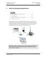
3 About the Example Applications
3.1 3.1.1 3.2 3.3 3.4 3.4.1 3.4.2 3.4.3 3.4.4 3.4.5 3.5 3.5.1 3.5.2 3.5.3 3.5.4 3.5.5 3.5.6 3.5.7 4 Support of Rack-optimized and Direct Connections ............................................... 54 Mix Rack-optimized and Direct Connections .......................................................... 54 System Components .............................................................................................. 55 Set Up the Hardware .............................................................................................. 56 Example 1 - Direct Connection and Rack Optimization ......................................... 57 Add the Relay Output Module and Configure for Direct Connection ...................... 57 Add the Digital Output Module and Configure for Rack Optimization .................... 60 Downloading the Sample Program to the Processor ............................................. 62 Verify the Chassis Size ........................................................................................... 63 View Module Data ................................................................................................... 66 Example 2 - Direct Connection ............................................................................... 67 Add the Relay Output Module and Configure for Direct Connection ...................... 67 Add the Digital Output Module and Configure for Direct Connection ..................... 70 Edit the Controller Tags .......................................................................................... 73 Create the Ladder Program .................................................................................... 74 Downloading the Sample Program to the Processor ............................................. 75 Verify the Chassis Size ........................................................................................... 76 View Module Data ................................................................................................... 79 Diagnostics and Troubleshooting
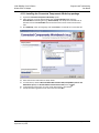
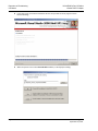
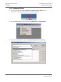
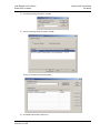
4.1 4.1.1 4.1.2 4.1.3 4.2 4.2.1 4.3 4.4 4.5 4.6 4.6.1 4.6.2 4.6.3 4.6.4 4.6.5 4.6.6 4.6.7 4.6.8 4.7 4.7.1 4.8 4.9 4.10 4.11 4.11.1 4.11.2 4.11.3 4.11.4 4.11.5 4.11.6 53 81 Connect to the Adapter's Web Page ...................................................................... 82 Diagnostics Pages .................................................................................................. 83 Configuration Pages ............................................................................................... 96 Browse Chassis Page ........................................................................................... 103 Viewing Wireless Statistics in RSLogix 5000 ....................................................... 105 Sources of Interference ........................................................................................ 106 Establish I/O Connections .................................................................................... 107 Recover From an Overloaded Adapter ................................................................. 107 Empty Slots and RIUP Situations ......................................................................... 108 LED Status Indicators ........................................................................................... 109 Module Status ....................................................................................................... 109 Network Activity .................................................................................................... 110 Network Status...................................................................................................... 110 POINTBus Status ................................................................................................. 110 System Power ....................................................................................................... 111 Field Power ........................................................................................................... 111 Wireless Link......................................................................................................... 111 Wireless Data........................................................................................................ 111 Check the Ethernet cable ..................................................................................... 112 Cable Connections ............................................................................................... 112 Restoring Factory Default Network Settings......................................................... 114 Restoring All Factory Default Settings .................................................................. 116 Installing a Replacement Wireless POINT I/O Adapter to an Existing System .... 117 Upgrading to Firmware Version 3.5.0 ................................................................... 118 Requirements........................................................................................................ 118 Installing the Connected Components Workshop package.................................. 119 Configuring RSLinx ............................................................................................... 122 Installing the Firmware Package........................................................................... 124 Flash programming the ILX34 .............................................................................. 125 Testing the new firmware installation ................................................................... 130 Page 8 of 209 ProSoft Technology, Inc. September 19, 2011 ILX34-AENWG ♦ Point I/O Platform
Wireless POINT I/O Adapter
5 Ladder Logic
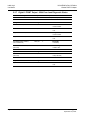
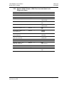
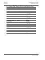
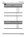
5.1 5.2 5.2.1 5.2.2 5.2.3 5.2.4 5.2.5 5.2.6 5.2.7 5.2.8 5.2.9 5.2.10 5.2.11 6 7 131 Adjusting the Input and Output Array Sizes (Optional) ......................................... 131 1734 POINT I/O Module/RSLogix 5000 Controller Tag Reference ...................... 133 1734 POINT I/O Catalog Numbers ....................................................................... 134 Valid Number Ranges for RSLogix 5000 Data Types........................................... 135 Digital 2 POINT Input ............................................................................................ 136 Digital 4 POINT Input ............................................................................................ 137 Digital 2 POINT Output - Without Diagnostic Status ............................................. 138 Digital 2 POINT Output - With Over Load and Open Load Diagnostic Status ...... 139 Digital 2 POINT Output - With Over Load Diagnostic Status ................................ 140 Digital 4 POINT Output - With Over Load and Open Load Diagnostic Status ...... 141 Digital 4 POINT Output - With Over Load Diagnostic Status ................................ 142 Analog 2 Channel Input ......................................................................................... 143 Specialty I/O .......................................................................................................... 157 Reference
6.1 6.1.1 6.1.2 6.1.3 6.1.4 6.2 6.2.1 6.2.2 6.2.3 6.2.4 6.3 6.3.1 6.3.2 6.3.3 6.4 6.4.1 6.4.2 6.5 6.5.1 6.5.2 6.5.3 6.5.4 6.5.5 6.5.6 6.5.7 6.5.8 6.5.9 6.6 6.6.1 6.7 6.8 Contents
User Manual
175 Product Specifications ........................................................................................... 175 General Specifications .......................................................................................... 176 Functional Specifications....................................................................................... 176 Hardware Specifications........................................................................................ 176 Supported Software and Hardware Versions ........................................................ 178 Functional Overview .............................................................................................. 179 About the Adapter ................................................................................................. 179 Understand the Producer/Consumer Model.......................................................... 179 Use of the Common Industrial Protocol (CIP) ....................................................... 180 Specify the Requested Packet Interval (RPI) ........................................................ 180 ILX34-AENWG Wireless Diagnostic Object (101,0x65) Vendor Specific ............. 181 Class Services Supported ..................................................................................... 181 Instance Services Supported ................................................................................ 182 Attributes Supported: Wireless Diagnostics Vendor Specific................................ 183 ILX34-AENWG Wireless Configuration Object (102, 0x66) Vendor Specific ........ 184 Instance Services Supported ................................................................................ 184 Attributes Supported.............................................................................................. 184 Antennas ............................................................................................................... 187 Antenna Pattern .................................................................................................... 187 Antenna Gain ........................................................................................................ 188 Antenna Polarity .................................................................................................... 188 Whip antennas ...................................................................................................... 188 Collinear array antennas ....................................................................................... 189 Yagi Array Antenna ............................................................................................... 189 Parabolic reflector antennas ................................................................................. 190 Adding bi-directional amplifiers ............................................................................. 190 Antenna location, spacing, and mounting ............................................................. 192 Configuring RSLinx ............................................................................................... 193 Configure the AB_ETH/IP Driver ........................................................................... 193 Using the ILX34-AENWG with Earlier Versions of RSLogix 5000 ........................ 195 Additional Point I/O Documentation ...................................................................... 195 Support, Service & Warranty
199 Contacting Technical Support ......................................................................................................... 199 ProSoft Technology, Inc. September 19, 2011 Page 9 of 209 Contents
User Manual
ILX34-AENWG ♦ Point I/O Platform
Wireless POINT I/O Adapter
7.1 7.1.1 7.1.2 7.1.3 7.2 7.2.1 7.2.2 7.2.3 7.2.4 7.2.5 7.2.6 7.2.7 7.2.8 7.2.9 7.2.10 Index
Return Material Authorization (RMA) Policies and Conditions ............................. 201 Returning Any Product.......................................................................................... 201 Returning Units Under Warranty........................................................................... 201 Returning Units Out of Warranty........................................................................... 202 LIMITED WARRANTY .......................................................................................... 203 What Is Covered By This Warranty ...................................................................... 203 What Is Not Covered By This Warranty ................................................................ 204 Disclaimer Regarding High Risk Activities ............................................................ 204 Intellectual Property Indemnity ............................................................................. 205 Disclaimer of all Other Warranties ........................................................................ 205 Limitation of Remedies ** ..................................................................................... 206 Time Limit for Bringing Suit................................................................................... 206 No Other Warranties ............................................................................................. 206 Allocation of Risks ................................................................................................ 206 Controlling Law and Severability .......................................................................... 206 207 Page 10 of 209 ProSoft Technology, Inc. September 19, 2011 ILX34-AENWG ♦ Point I/O Platform
Wireless POINT I/O Adapter
Guide to the ILX34-AENWG User Manual
User Manual
Guide to the ILX34-AENWG User Manual
Section
Quick Link
Contents
Install the ILX34‐AENWG Adapter (Required) Start Here (page 37)
Configure the ILX34‐
AENWG Adapter (Required) Configure the ILX34‐
AENWG Adapter (page
37)
Diagnostics and Troubleshooting Diagnostics and
Troubleshooting (page
81)
About the Sample Applications About the Sample Applications (page 179, page 53)s
Functional Overview Functional Overview (page 179, page 53)
Support, Service, and Warranty Index Support, Service and Warranty (page 199)
System Requirements & Package Contents Installing the ILX34‐AENWG in the POINT I/O Chassis Configuring the POINT I/O Processor Connecting to the ILX34‐AENWG Adapter Adapter Configuration Interface Adapter Configuration Port Configuration Protocol Configuration LED Status Indicators Diagnostics Troubleshooting Direct Connection Rack Optimization General Concepts About the AENWG Protocol Data Transfer Between ILX34‐AENWG Adapter and POINT I/O Processor Obtaining Technical Support Contacting ProSoft Technology License and Warranty Index ProSoft Technology, Inc. September 19, 2011 Page 11 of 209 Guide to the ILX34-AENWG User Manual
User Manual
ILX34-AENWG ♦ Point I/O Platform
Wireless POINT I/O Adapter
Page 12 of 209 ProSoft Technology, Inc. September 19, 2011 ILX34-AENWG ♦ Point I/O Platform
Wireless POINT I/O Adapter
1
Start Here
User Manual
Start Here
In This Chapter
Overview ........................................................................................................... 14
Package Contents .............................................................................................. 14
System Requirements ....................................................................................... 15
Install the Configuration Tools .......................................................................... 16
Planning the Network ........................................................................................ 17
Planning the Physical Installation ...................................................................... 19
Configure the Wireless Access Point ................................................................. 19
Install the Adapter ............................................................................................. 22 To get the most benefit from this User Manual, you should have the following skills:
Rockwell Automation® RSLogix™ software: launch the program, configure ladder logic, and transfer the ladder logic to the processor Microsoft Windows: install and launch programs, execute menu commands, navigate dialog boxes, and enter data. Hardware installation and wiring: install the adapter, and safely connect AENWG and POINT I/O devices to a power source and to the ILX34‐AENWG adapter’s application ports. Caution: You must be able to complete the application without exposing personnel or
equipment to unsafe or inappropriate working conditions.
Important: You must use series C POINT I/O modules with the ILX34-AENWG adapter. Series A
or B POINT I/O modules will not work with this adapter.
ProSoft Technology, Inc. September 19, 2011 Page 13 of 209 Start Here
User Manual
1.1
ILX34-AENWG ♦ Point I/O Platform
Wireless POINT I/O Adapter
Overview
The ILX34 Wireless Point I/O is a wireless input/output interface that can provide wireless data transfer functionality between automation systems based on a diverse range of controllers and processors. Supported systems include:
Rockwell Automation® (RA) ControlLogix® Programmable Automation Controller (PAC) systems RA CompactLogix™ (CPLX) PAC systems The Wireless POINT I/O benefits users who require a non‐tethered link to distributed I/O in applications with moving, remote, or difficult / costly to wire devices or control panels. Customers may also choose to use wireless I/O to save time and money versus installation of wire. 1.2
Package Contents
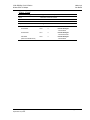
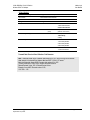
The following components are included with your ILX34‐AENWG adapter, and are all required for installation and configuration. Important: Before beginning the installation, please verify that all of the following items are
present.
Qty.
Part Name
Part Number
Part Description
1 ILX34‐AENWG Adapter ILX34‐AENWG Wireless POINT I/O Adapter 1 Antenna A2405S‐OA 2.4 GHz Articulating Omni Antenna 1 ILX34‐AENWG CD Contains utilities and documentation for the ILX34‐AENWG adapter. If any of these components are missing, please contact ProSoft Technology Support for replacement parts. Page 14 of 209 ProSoft Technology, Inc. September 19, 2011 ILX34-AENWG ♦ Point I/O Platform
Wireless POINT I/O Adapter
1.3
Start Here
User Manual
System Requirements
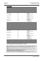
The ILX34‐AENWG adapter requires the following minimum hardware and software components:
Rockwell Automation® processor, with compatible power supply ®
o ControlLogix 1756‐L6x (firmware version 17.03 or higher), or 1756‐6xS (firmware version 17.07 or higher) or o CompactLogix™ 1769‐L32E or 1769‐L35E, (firmware version 17.04 or higher) Rockwell Automation RSLogix 5000 programming software version 16 or higher (page 195). Version 17 is required if you wish to use the ILX34‐AENWG Add‐On Profile. Rockwell Automation RSLinx communication software version 2.54 or higher An 802.11g Radio. ProSoft recommends the RLXIB‐IHW 802.11 a/b/g Industrial Hotspot (page 19). If you plan to use the ILX34‐AENWG with a 1756‐ENBT module or 1768‐ENBT module, note the following firmware version requirements: o 1756‐ENBT firmware revision 4.007 or later o 1768‐ENBT firmware revision 2.003 or later o Use BootP revision 2.3.2 or later to assign IP addresses to the adapter. Pentium® II 450 MHz minimum. Pentium III 733 MHz (or better) recommended Supported operating systems: o Microsoft Windows Vista o Microsoft Windows XP Professional with Service Pack 1 or 2 o Microsoft Windows 2000 Professional with Service Pack 1, 2, or 3 o Microsoft Windows Server 2003 128 Mbytes of RAM minimum, 256 Mbytes of RAM recommended Microsoft Windows Explorer version 7 256‐color VGA graphics adapter, 800 x 600 minimum resolution (True Color 1024 768 recommended) CD‐ROM drive Note: The Hardware and Operating System requirements in this list are the minimum
recommended to install and run software provided by ProSoft Technology. Other third party
applications may have different minimum requirements. Refer to the documentation for any third
party applications for system requirements.
ProSoft Technology, Inc. September 19, 2011 Page 15 of 209 Start Here
User Manual
1.4
ILX34-AENWG ♦ Point I/O Platform
Wireless POINT I/O Adapter
Install the Configuration Tools
1.4.1 Install the ILX34-AENWG Add-On Profile
1
Verify that your computer meets the hardware and operating system requirements. (page 15) Important: You must have "Administrator" rights on your computer to install this application.
2
3
4
5
6
Insert the ProSoft Solutions CD‐ROM in an available CD‐ROM drive in your computer. On most computers, the installation program will start automatically within a few seconds. If the installation does not start automatically on your computer, click the START button, choose RUN, and then type explorer. Click OK to start Windows Explorer. In Windows Explorer, open the MY COMPUTER icon and navigate to the CD‐ROM drive. Navigate to the folder containing the ILX34‐AENWG Add‐On Profile, and then double‐click the file SETUP.EXE. This action starts the installation wizard. Follow the instructions on the installation wizard to install the program. Click FINISH to complete the installation. If you are prompted to restart your computer, save your work in any applications that are running, close the applications, and allow the computer to restart. 1.4.2 Install ProSoft Wireless Designer
1
2
3
On the CD‐ROM, navigate to the folder containing ProSoft Wireless Designer, and then double‐click the file SETUP.EXE. This action starts the installation wizard. Follow the instructions on the installation wizard to install the program. Click FINISH to complete the installation. If you are prompted to restart your computer, save your work in any applications that are running, close the applications, and allow the computer to restart. Page 16 of 209 ProSoft Technology, Inc. September 19, 2011 ILX34-AENWG ♦ Point I/O Platform
Wireless POINT I/O Adapter
1.5
Start Here
User Manual
Planning the Network
Before you configure and install the network, you should create a plan for it. The following points assume that you are creating a bridge network of masters and repeaters, but you can also set up clients to work with devices on existing wireless LANs. For information, see Set up a Client. The simplest way to design the physical network of radios, antennas, connectors, cables, amplifiers and other accessories, is to use ProSoft Wireless Designer (page 18). This application determines your hardware needs based on your answers to a few questions, and then generates a Bill of Materials specifying all the components you will need for your installation.
To begin, determine where you need radios and then choose locations for them accordingly. For example, you might decide to install your master radio near a PC in a central plant location (You can use the PC to configure the radios through the Radio Configuration / Diagnostic Utility). If the plant is an oil refinery, for example, you might decide to install radios near the oil tanks. The next important issue is how to link the radios. Unless the radios are very close together, you must make sure that each pair of radio antennas in the network has a line of sight between them. In other words, you must be able to see from one antenna to another, either with the naked eye, or with binoculars. If a line of sight does not exist between antennas, you must choose a site for installing a repeater radio, which will create a bridge between the radio antennas. Choose the appropriate antennas for the network. If an antenna will be connected to the radio by a long cable, you might need to purchase a power amplifier, which is available from ProSoft Technology. The more distance between an antenna and its radio, the more signal loss the radio will have. Consider drawing up your network plans on paper. As part of the drawing, you should assign a logical name to each radio. You can use these names later when configuring the radios in the Radio Configuration / Diagnostic Utility. As part of your planning, you might want to conduct a site survey. ProSoft Technology can perform this survey, you can do it yourself, or you can hire a surveyor. Protect radios from direct exposure to weather, and provide an adequate, stable power source. Make sure that your plan complies with the radio’s power requirements and cable specifications. Important: Radios and antennas must be located at least 8 inches (20 cm) away from personnel.
ProSoft Technology, Inc. September 19, 2011 Page 17 of 209 Start Here
User Manual
ILX34-AENWG ♦ Point I/O Platform
Wireless POINT I/O Adapter
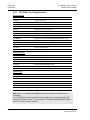
1.5.1 Installation Questions
Answer the following questions to make your installation easier, and to familiarize yourself with your system and what you want to do. How many radios in your network? Master ID Repeater ID ILX34‐AENWG ID Locations Is there a Line of Sight between them? Selected the appropriate antennas for your network? 1.5.2 ProSoft Wireless Designer
ProSoft Wireless Designer simplifies the task of specifying a ProSoft Wireless installation, and provides a variety of views containing an accurate description of each site in a wireless network, including:
Visual diagram of site layout Location (latitude/longitude, based on GPS coordinates) Radio type, frequency range, and country‐specific channel and power requirements Length, type and estimated signal loss for cables Required accessories, including lightning protection, cable adaptors and antennas Complete parts list Use ProSoft Wireless Designer when conducting a site audit for a customer, and then provide the customer with a complete list of components and a detailed description for each site and link. Customers can use this information to understand and visualize their network, and provide necessary information for technical support and maintenance. Functional Specifications:
Contains a database of all currently available RadioLinx radios, antennas, cables, connectors and accessories Exports Parts List, Site and Link Details, and Wizard settings into a variety of common file formats, for import into applications such as spreadsheets, databases and word processors Checks wireless link feasibility based on path length and recommended accessories Predicts signal strength based on distance, local regulations and hardware choices Fully documents your ProSoft Wireless network plan Page 18 of 209 ProSoft Technology, Inc. September 19, 2011 ILX34-AENWG ♦ Point I/O Platform
Wireless POINT I/O Adapter
Start Here
User Manual
1.5.3 WirelessN Discovery Tool Functional Specifications
The ProSoft WirelessN Discovery Tool supports the following network discovery and monitoring activities:
1.6
Discover and view the list of radios in the network Display graphically the current network topology and display parent‐child links between various radios in the network Scan the network on demand Save and load network snapshots Upload and download configuration files to/from radio devices Upgrade Radio firmware Planning the Physical Installation
A network's performance is affected by attributes specific to the installation site. Consider the following cautions, where possible, to optimize your network installation:
Design the network to use less than 2048 radios (per network) Place radios within the specified 15 miles of each other Add repeater to extend distance or where line of sight is limited Radios or antennas CANNOT be placed within 8 inches (20 cm) of where people will be Though radio frequency communication is reliable, sometimes its performance can be affected by intangibles. A good network installation plan includes time and resources for performance testing and installation changes. Test the installation plan (page 51) before the network installation is complete. 1.7
Configure the Wireless Access Point
Although the ILX34‐AENWG can communicate with any 802.11b/g Access Point radio, ProSoft Technology recommends the RadioLinx series Industrial Broadband radios wherever performance and compatibility are required. The following configuration steps are for the RLXIB‐IHW. Use the examples in these steps to configure your own Access Point to work with the ILX34‐AENWG. ProSoft Technology, Inc. September 19, 2011 Page 19 of 209 Start Here
User Manual
ILX34-AENWG ♦ Point I/O Platform
Wireless POINT I/O Adapter
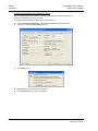
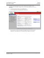
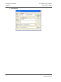
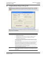
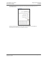
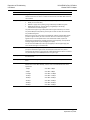
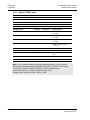
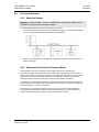
1.7.1 Configure the Master Radio (Required)
The following illustration shows an example configuration for a RadioLinx Industrial Hotspot (Access Point) configured as a Master radio. Note: The radio in this illustration is capable of transmitting at 5 GHz (802.11a) as well as 2.4 GHz
(802.11b/g). The radio in the ILX34-AENWG adapter supports only 2.4 GHz (802.11b/g).
In particular, note the following settings.
Network SSID: All radios on the network must use the same Network SSID In this example, the Network SSID is "Point_IO". Channel: All radios must use the same channel. In this example, the channel is 8 (2447MHz). Encryption: All radios must use the same encryption settings. In this example, the encryption type is WPA/WPA2‐AES. Passphrase: All radios must use the same passphrase. For security reasons, the passphrase field is replaced with asterisks. Make a note of the passphrase before configuring additional radios. Important: Take care to enter the passphrase on the ILX34-AENWG exactly as you entered it in
the Master radio.
IP Address: The IP address for all radios must be within the same subnet, and each radio requires its own unique IP address. You can assign static IP addresses, as in this example, or you can use DHCP (Dynamic Host Control Protocol) to manage and assign IP addresses automatically (page 25). Note: Refer to the documentation for your radio (for example, the RLXIB-IHW User Manual) for
specific steps to configure the settings in this example.
Page 20 of 209 ProSoft Technology, Inc. September 19, 2011 ILX34-AENWG ♦ Point I/O Platform
Wireless POINT I/O Adapter
Start Here
User Manual
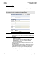
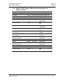
1.7.2 Configure One or More Repeaters (Optional)
The following illustration shows an example configuration for a RadioLinx Industrial Hotspot (Access Point) configured as a Repeater radio. The need for repeater radios is determined by the distance between the Master radio and the ILX34‐AENWG, as well as any topographical factors such as hills or other obstructions, which could prevent a clear line‐of‐sight signal path. Note: The radio in this illustration is capable of transmitting at 5 GHz (802.11a) as well as 2.4 GHz
(802.11b/g). The radio in the ILX34-AENWG adapter supports only 2.4 GHz (802.11b/g).
In particular, note the following settings.
Network SSID, Channel, Encryption and Passphrase for the Repeater radio must match those configured for the Master radio and the ILX34‐AENWG. IP Address: The IP address for all radios must be within the same subnet, and each radio requires its own unique IP address. You can assign static IP addresses, as in this example, or you can use DHCP (Dynamic Host Control Protocol) to manage and assign IP addresses automatically (page 25). Note: Refer to the documentation for your radio (for example, the RLXIB-IHW User Manual) for
specific steps to configure the settings in this example.
ProSoft Technology, Inc. September 19, 2011 Page 21 of 209 Start Here
User Manual
1.8
ILX34-AENWG ♦ Point I/O Platform
Wireless POINT I/O Adapter
Install the Adapter
Attention: You must use series C POINT I/O modules with the ILX34-AENWG adapter. Series A
or B POINT I/O modules will not work with this adapter.
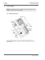
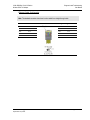
1.8.1 Adapter Components
The Wireless POINT I/O Adapter is a communications adapter for POINT I/O modules. The adapter provides an interface for controlling and communicating with POINT I/O modules from an Ethernet network. Page 22 of 209 ProSoft Technology, Inc. September 19, 2011 ILX34-AENWG ♦ Point I/O Platform
Wireless POINT I/O Adapter
Start Here
User Manual
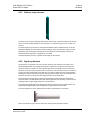
1.8.2 Install the Wireless Point I/O Adapter on the DIN-rail
Warning: You must follow all safety instructions when installing this or any other electronic
devices. Failure to follow safety procedures could result in damage to hardware or data, or even
serious injury or death to personnel. Refer to the documentation for each device you plan to
connect to verify that suitable safety procedures are in place before installing or servicing the
device.
1
2
Position the adapter vertically above the DIN‐rail. Press down firmly to install the adapter on the DIN‐rail, and then turn the orange screw to lock the adaptor onto the DIN‐rail. Warning: If you connect or disconnect the Ethernet cable with power applied to this module or any
device on the network, an electrical arc can occur. This could cause an explosion in hazardous
location installations.
Be sure that power is removed or the area is nonhazardous before proceeding.
3
Slide the safety end cap up to remove. This exposes the backplane and power interconnections. Caution: Do not discard the end cap. Use this end cap to cover the exposed interconnections on
the last mounting base on the DIN-rail. Failure to do so could result in equipment damage or injury
from electric shock.
Important: You must use series C POINT I/O modules with the ILX34-AENWG adapter. Series A
or B POINT I/O modules will not work with this adapter.
1.8.3 Connect Power to the Adapter
The ILX34‐AENWG adapter requires an external source of DC voltage. The DC source voltage should be 24V nominal, with a range of 10V to 28.8V. Refer to the following illustrations for wiring information. ProSoft Technology, Inc. September 19, 2011 Page 23 of 209 Start Here
User Manual
ILX34-AENWG ♦ Point I/O Platform
Wireless POINT I/O Adapter
Caution: Do not connect 120/240V ac power to this supply.
Warning: If you connect or disconnect wiring while the field-side power is on, an electrical arc can
occur. This could cause an explosion in hazardous location installations.
Be sure that power is removed or the area is nonhazardous before proceeding.
When you power up the POINT I/O for the first time, the adapter must assign addresses to every module in the backplane. POINT I/O modules are all initially configured at the same address. When you first apply power, all but one module on the backplane should show a solid red Module Status LED. One by one, the adapter resets these modules and assigns addresses. The amount of time that this operation takes depends on the size of your POINT I/O system. Page 24 of 209 ProSoft Technology, Inc. September 19, 2011 ILX34-AENWG ♦ Point I/O Platform
Wireless POINT I/O Adapter
Start Here
User Manual
1.8.4 Connect the Adapter to the EtherNet/IP Network
Connect an Ethernet cable between the adapter’s Ethernet port, and the EtherNet/IP network. Note: This connection is temporary, and is helpful during configuration. You will disconnect the
Ethernet cable after you have finished configuring the adapter for wireless communication.
1.8.5 Configure the Adapter for Your EtherNet/IP Network
Before using your adapter in an EtherNet/IP network, configure it with an IP address, subnet mask, and optional Gateway address. This chapter describes these configuration requirements and the procedures for providing them. Here are ways you can do this:
Use the Rockwell BootP utility, version 2.3 or later, which ships with RSLogix 5000 or RSLinx software. (page 29) You can also use this utility to reconfigure a device with an IP address you must change.
Use a third party DHCP server. (page 27) Use the Network Address thumbwheel switch. (page 25) Important: You must use series C POINT I/O modules with the ILX34-AENWG adapter. Series A
or B POINT I/O modules will not work with this adapter.
ProSoft Technology, Inc. September 19, 2011 Page 25 of 209 Start Here
User Manual
ILX34-AENWG ♦ Point I/O Platform
Wireless POINT I/O Adapter
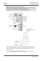
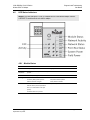
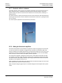
Configure the IP Address with the Thumbwheel Switches
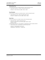
ore you can connect to the ILX34‐AENWG for the first time, you must configure its IP address. The simplest way to set the IP address for your initial connection is to use the thumbwheel switches on the front of the adapter. The three thumbwheel switches represent the final octet for the private IP address 192.168.1.xxx (where xxx represents the number set on the switches). The factory default switch setting is 999. Use the buttons above and below each number to select a temporary IP address to use. Choose a number between 001 and 254, taking care not to duplicate the IP address of any other device on the network. NOTE: Settings 777 and 888 are reserved and used for special functions. For details, see
Restoring All Factory Default Settings (page 116).
If you set the switches to an invalid number (that is, 000 or a value greater than 254), the adapter checks to see if you enabled DHCP, according to the following table. If DHCP is
Then the adapter
Enabled Asks for an address from a DHCP server. The DHCP server also assigns other Transport Control Protocol (TCP) parameters. Not enabled Uses the IP address (along with other TCP configurable parameters) stored in nonvolatile memory The updated IP address setting will take effect when the adapter is powered up. Page 26 of 209 ProSoft Technology, Inc. September 19, 2011 ILX34-AENWG ♦ Point I/O Platform
Wireless POINT I/O Adapter
Start Here
User Manual
Using DHCP Software to Configure Your Adapter
DHCP (Dynamic Host Configuration Protocol) software automatically assigns IP addresses to client stations logging onto a TCP/IP network. DHCP is based on BootP and maintains some backward compatibility. The main difference is that BootP was designed for manual configuration, while DHCP allows for dynamic allocation of network addresses and configurations to newly attached devices. Be cautious about using DHCP software to configure your adapter. A DHCP server typically assigns a finite lease time to the offered IP address. When 50% of the leased time has expired, the ILX34‐AENWG adapter attempts to renew its IP address with the DHCP server. The possibility exists that the adapter will be assigned a different IP address, which would cause the adapter to cease communicating with the ControlLogix controller. Refer to Configure the ILX34‐AENWG Adapter with Fixed IP Address (page 28). Caution: To avoid unintended control, the ILX34-AENWG adapter must be assigned a fixed IP
address. The IP address of this adapter should not be dynamically provided. If a DHCP server is
used, it must be configured to assign a fixed IP address for your adapter.
Failure to observe this precaution may result in unintended machine motion or loss of process
control.
ProSoft Technology, Inc. September 19, 2011 Page 27 of 209 Start Here
User Manual
ILX34-AENWG ♦ Point I/O Platform
Wireless POINT I/O Adapter
Configuring the Adapter with Fixed IP Address
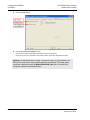
A fixed IP address prevents the adapter from losing a dynamically assigned IP address and ceasing to communicate with the controller: To configure the ILX34‐AENWG adapter with a fixed IP address 1
2
Click the PORT CONFIGURATION tab in the ILX34‐AENWG adapter properties dialog. Unselect (uncheck) the ENABLE DHCP check box. 3
Click the SET button. 4
5
Click OK to dismiss the confirmation dialog box. Click the REFRESH button to verify the changes. Page 28 of 209 ProSoft Technology, Inc. September 19, 2011 ILX34-AENWG ♦ Point I/O Platform
Wireless POINT I/O Adapter
Start Here
User Manual
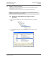
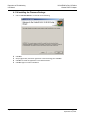
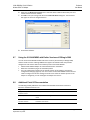
Using the Rockwell BootP/DHCP Utility
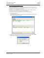
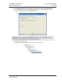
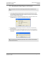
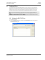
The Rockwell BOOTP/DHCP utility is a stand‐alone program that incorporates the functionality of standard BootP software with a user‐friendly graphical interface. You can install BootP from the UTILS directory on the RSLogix5000 installation CD. To use BootP, you must enable DHCP on ILX34‐AENWG adapter, and the adapter's network address switches must be set to a value greater than 255 (page 25). To configure your adapter using the BootP utility, perform the following steps: 1
Run the BootP software. In the BOOTP REQUEST HISTORY pane, you will see the hardware addresses of devices on the network that are issuing BootP requests. 2
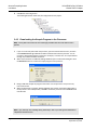
Double‐click the hardware address of the device to configure. This action opens the NEW ENTRY dialog bow, populated with the device's Ethernet Address (MAC). ProSoft Technology, Inc. September 19, 2011 Page 29 of 209 Start Here
User Manual
3
ILX34-AENWG ♦ Point I/O Platform
Wireless POINT I/O Adapter
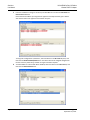
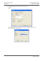
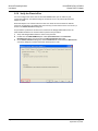
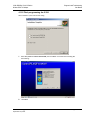
Enter the IP Address to assign to the device, and click OK. You can leave the HOSTNAME and DESCRIPTION fields blank. Notice that the IP Address you assigned now appears in the Request History pane. Notice also that the device now appears in the Relation List pane. To assign this configuration to the device, select the device in the RELATION LIST pane, and then click the DISABLE BOOTP/DHCP button. The device will use the assigned configuration the next time it is powered up, and will no longer issue DHCP requests. 4
To enable DHCP for a device with DHCP disabled, select the device in the RELATION LIST, and then click the ENABLE DHCP button. Page 30 of 209 ProSoft Technology, Inc. September 19, 2011 ILX34-AENWG ♦ Point I/O Platform
Wireless POINT I/O Adapter
Start Here
User Manual
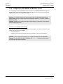
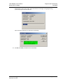
Save the Relation List
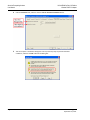
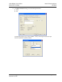
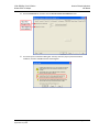
You can save the Relation List to use later, for example, to have a record of IP addresses assigned to specific MAC addresses. 1
Open the FILE menu, and then choose SAVE AS. This action opens the SAVE AS dialog box. 2
Enter a File name for the Relation List (for example, control system configuration), and click SAVE. ProSoft Technology, Inc. September 19, 2011 Page 31 of 209 Start Here
User Manual
ILX34-AENWG ♦ Point I/O Platform
Wireless POINT I/O Adapter
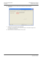
1.8.6 Configure the ILX34-AENWG for Wireless Access
You can configure the ILX34‐AENWG's wireless settings from the MODULE PROPERTIES dialog box in RSLogix 5000, or from the ILX34‐AENWG's web page (page 32). The first time you configure the adaptor, you should use the adapter's web page. Important: The wireless settings for the ILX34-AENWG must be compatible with the Industrial
Hotspot radio (page 19) connected to the Ethernet bridge (for example, a 1756-ENBT module in a
ControlLogix rack).
Important: All radios on the network must use the same settings, otherwise they will be unable to
communicate with each other.
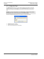
Connect to the Adapter's Web Page
Open your web browser (for example, Microsoft Internet Explorer or Firefox), and connect to the adapter's temporary network address. http://192.168.1.xxx (where xxx is the value you entered in the rotary switches on the front of the adapter.) Important: Your PC must be on the same TCP/IP subnet as the adaptor to view these pages.
Important: You must prefix the numeric IP address with "http://", otherwise the web browser
may not be able to interpret the address.
Page 32 of 209 ProSoft Technology, Inc. September 19, 2011 ILX34-AENWG ♦ Point I/O Platform
Wireless POINT I/O Adapter
Start Here
User Manual
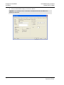
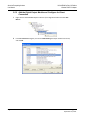
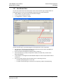
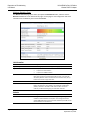
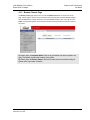
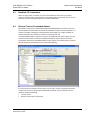
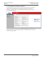
The adapter's home page consists of a tree view in the left pane for navigation, and an information pane in the middle. The right column contains links for additional resources and information.
To view the contents of a folder, click the EXPAND button. To select a page to view, click the page title in the tree view. If you are unable to connect to the adapter's web page, verify that your PC is correctly configured to reach IP addresses on the subnet where your adapter communicates. ProSoft Technology, Inc. September 19, 2011 Page 33 of 209 Start Here
User Manual
ILX34-AENWG ♦ Point I/O Platform
Wireless POINT I/O Adapter
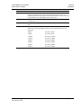
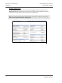
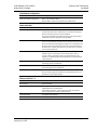
Wireless Settings Page
The WIRELESS SETTINGS page opens when you select the CONFIGURATION folder in the menu on the left side of the page, and then click the WIRELESS SETTINGS link. Use this page to configure the radio settings for the adapter. Important: The values on this page are in non-volatile memory. Changes to these parameters do
not take effect until you reset or cycle power to the ILX34-AENWG adapter.
Field
Description
SSID Assign a network name (SSID) of up to 32 characters. The radio uses this name in all network references. All radios in a network must have the same SSID. SSID names are case‐sensitive. Encryption Type Choose the method by which the adapter will apply encryption security:
NONE (not recommended)
WEP128 ‐ Legacy security setting using a 128‐bit key and WEP encryption.
WPA2/AES (Preferred) ‐ Security setting using WPA (pre‐shared key) authentication and AES encryption. The preferred encryption type is AES (Advanced Encryption Standard). You should only select WEP (wired equivalency protocol) for use with an older client radio that only has WEP encryption. WEP is the original security protocol used by 802.11 networks, but AES offers better protection against attacks, for several reasons: AES uses an advanced encryption algorithm that is not susceptible to the same weaknesses as WEP, it performs dynamic key management by changing the session keys frequently, and it performs message integrity checks to prevent forgery and replay. You can also select WEP 128, or None (no encryption) as the encryption type, but none of these settings are recommended. Page 34 of 209 ProSoft Technology, Inc. September 19, 2011 ILX34-AENWG ♦ Point I/O Platform
Wireless POINT I/O Adapter
Start Here
User Manual
Field
Description
WPA Passphrase To use WPA2/AES encryption on packets sent between the radios, enter a WPA2/AES pass phrase of between eight and 63 normal keyboard characters. This phrase automatically generates an encryption key of 128 hexadecimal characters. This field is only available if you select WPA2/AES as the encryption type. WEP Key Index If using WEP128 encryption, select the Key Index that matches the Key Index used in the Access Point. WEP Keys (1‐4) If using WEP128 encryption, enter the WEP Keys that match the Keys in the Access Point. Transmit Data Rate The recommended The ILX34‐AENWG supports the following transmit data rates. The default value is Auto: Max 54 Mbps, and this is the recommended value for most applications. 1 Mbps Auto: Max. 1 Mbps 2 Mbps Auto: Max. 2 Mbps 5.5 Mbps Auto: Max. 5.5 Mbps 11 Mbps Auto: Max. 11 Mbps 18 Mbps Auto: Max. 18 Mbps 24 Mbps Auto: Max. 24 Mbps 36 Mbps Auto: Max. 36 Mbps 54 Mbps Auto: Max. 54 Mbps ProSoft Technology, Inc. September 19, 2011 Page 35 of 209 Start Here
User Manual
ILX34-AENWG ♦ Point I/O Platform
Wireless POINT I/O Adapter
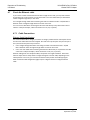
Verify Wireless Communication
At this point, with the Ethernet cable still attached to the ILX34‐AENWG, go to the WIRELESS STATISTICS web page, and verify that the ILX34‐AENWG is linked to the Access Point. After the link is established, you should disconnect the Ethernet cable from the ILX34 and reconnect it to the Access Point. From this point on, all communications can be done wirelessly. Note: If Ethernet cables are connected to both the ILX34-AENWG and the Access Point, and there
is a wireless link between these devices, a loop will be formed. Typically the Access Point detects
this loop and disconnects the wireless link. In this condition, the link LED on the ILX34-AENWG will
periodically come on and then go off. Also, the Wireless Statistics web page will sometimes show
the unit is linked and then later show that it is not.
Page 36 of 209 ProSoft Technology, Inc. September 19, 2011 ILX34-AENWG ♦ Point I/O Platform
Wireless POINT I/O Adapter
2
Configure the ILX34-AENWG
User Manual
Configure the ILX34-AENWG
In This Chapter
Create a New RSLogix 5000 Project ................................................................... 37
Create the Network ........................................................................................... 39
Create the Adapter ............................................................................................ 41
Add POINT Modules Under the Adapter ........................................................... 44
Configure 1734 POINT I/O Modules .................................................................. 45
Configuring Wireless Settings in RSLogix 5000 .................................................. 49
Install the Antenna ............................................................................................ 50
Test the Network Installation Plan .................................................................... 51 2.1
Create a New RSLogix 5000 Project
Note: The following steps require RSLogix 5000 version 17 or newer, and a processor with
firmware compatible with this version of RSLogix 5000. To use the ILX34-AENWG adapter with an
earlier version of RSLogix 5000 or the processor firmware, please refer to Using the ILX34AENWG with Earlier Versions of RSLogix 5000 (page 195).
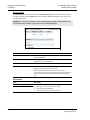
1
Open the FILE menu, and then choose NEW… ProSoft Technology, Inc. September 19, 2011 Page 37 of 209 Configure the ILX34-AENWG
User Manual
2
ILX34-AENWG ♦ Point I/O Platform
Wireless POINT I/O Adapter
Select REVISION 17. Page 38 of 209 ProSoft Technology, Inc. September 19, 2011 ILX34-AENWG ♦ Point I/O Platform
Wireless POINT I/O Adapter
2.2
Configure the ILX34-AENWG
User Manual
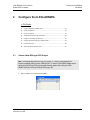
Create the Network
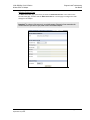
1
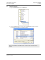
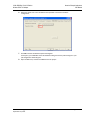
Right‐click I/O CONFIGURATION and choose NEW MODULE… 2
Expand the COMMUNICATIONS node, and then select the ETHERNET BRIDGE module that matches your hardware. This example uses a 1756‐ENBT/A module. Note: If you are prompted to "Select Major Revision", choose the lower of the available revision
numbers.
ProSoft Technology, Inc. September 19, 2011 Page 39 of 209 Configure the ILX34-AENWG
User Manual
3
ILX34-AENWG ♦ Point I/O Platform
Wireless POINT I/O Adapter
Name the ENBT/A module, then set the IP Address and slot location in the local rack with the ControlLogix processor. 4
Click OK. Page 40 of 209 ProSoft Technology, Inc. September 19, 2011 ILX34-AENWG ♦ Point I/O Platform
Wireless POINT I/O Adapter
2.3
Configure the ILX34-AENWG
User Manual
Create the Adapter
1
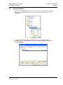
Next, select the 1756‐ENBT module that you just created in the Controller Organization pane and click the right mouse button to open a shortcut menu. On the shortcut menu, choose NEW MODULE. 2
In the SELECT MODULE dialog box, click the VENDOR tab, and then expand the PROSOFT TECHNOLOGY node. Click the BY VENDOR tab, expand the PROSOFT TECHNOLOGY node, and then select ILX34‐AENWG. ProSoft Technology, Inc. September 19, 2011 Page 41 of 209 Configure the ILX34-AENWG
User Manual
3
ILX34-AENWG ♦ Point I/O Platform
Wireless POINT I/O Adapter
Name the ILX34‐AENWG adapter, and set the IP address. Important: The IP address on the ILX34-AENWG's thumbwheel switches must match the IP
address you enter here.
Page 42 of 209 ProSoft Technology, Inc. September 19, 2011 ILX34-AENWG ♦ Point I/O Platform
Wireless POINT I/O Adapter
Configure the ILX34-AENWG
User Manual
2.3.1 Configure Chassis Size
The ILX34‐AENWG requires configuration of its chassis size before you can make any I/O connections. The default setting for the chassis size is 1 slot, which represents the adapter by itself, and allows for no I/O. You must set the chassis size to a number equaling 1 slot for the adapter plus 1 slot for each I/O module present in the adapter's backplane. For example, the adapter plus 2 I/O modules uses a chassis size of 3. The adapter stores this chassis size setting in non‐volatile storage. When the adapter's non‐volatile chassis size does not match the actual number of modules present on its backplane, the adapter does not make any I/O connections and an error occurs. 1
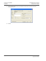
In the Module Definition area of the General tab, click the CHANGE button. This action opens the MODULE DEFINITION dialog box. 2
Select the Chassis Size for your project from the dropdown list, and then Click OK to close the MODULE DEFINITION dialog box. In a later step, you will verify the chassis size when you are online with the ILX34‐AENWG (page 45). ProSoft Technology, Inc. September 19, 2011 Page 43 of 209 Configure the ILX34-AENWG
User Manual
2.4
ILX34-AENWG ♦ Point I/O Platform
Wireless POINT I/O Adapter
Add POINT Modules Under the Adapter
1
Right‐click the ILX34‐AENWG adapter under I/O configuration to add a new module. Your second module is in slot 1. 2
3
Select the module from the MODULE TYPE list, and click OK. In the MODULE PROPERTIES dialog, enter the following information: a) Name b) Slot 4
Click the CONNECTION tab, and set the RPI: o
o
5
For digital modules, enter 10 ms For analog or specialty modules, enter 50 ms. Click FINISH. Repeat these steps to add all of the POINT I/O modules connected to the ILX34‐AENWG adapter. Page 44 of 209 ProSoft Technology, Inc. September 19, 2011 ILX34-AENWG ♦ Point I/O Platform
Wireless POINT I/O Adapter
2.5
Configure the ILX34-AENWG
User Manual
Configure 1734 POINT I/O Modules
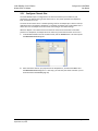
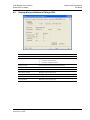
The preferred method to configure POINT I/O modules is to use the MODULE PROPERTIES dialog box for each POINT I/O module, as described in the User Manual for the module. The following steps show you how to configure the module by editing the Controller Tags. 1
In the CONTROLLER ORGANIZATION window, double‐click CONTROLLER TAGS, and then click the MONITOR TAGS tab, at the bottom left corner of the Controller Tags dialog box. Look at the bottom of the screen to make sure you are in the Monitor Tags tab. In this example, you will configure an analog input module 1734‐IE2V, installed in slot 1. You will configure Channel 0 of this module to operate over the range ‐10 to +10V dc. 2
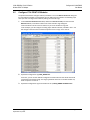
Expand the configuration tag ILX34_AENWG:2:C. From here, you can set the module's configuration and alarms.Enter the values that would correspond to the desired range. The range type default value for a 1734‐IE2V module is 2, which is equal to 0 to 10V dc. 3
Expand the configuration tag for the module in slot 4, ILX34_AENWG:2:CH0RANGETYPE. ProSoft Technology, Inc. September 19, 2011 Page 45 of 209 Configure the ILX34-AENWG
User Manual
4
ILX34-AENWG ♦ Point I/O Platform
Wireless POINT I/O Adapter
View the value in the tag ILX34_AENWG:2:C.CH0RANGETYPE. The default value for this tag is 2. The module supports the following Ch0Range Type values: o
o
2 = 0 to 10V dc 0 = ‐10 to +10V dc Page 46 of 209 ProSoft Technology, Inc. September 19, 2011 ILX34-AENWG ♦ Point I/O Platform
Wireless POINT I/O Adapter
5
Configure the ILX34-AENWG
User Manual
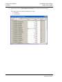
Click the value 2 and change it to 0, which changes the voltage range to ‐10 to +10V dc for channel 0. Note the following: o
o
The controller sends the configuration data only when it first establishes the connection. After you modify any of the tag values, you must download the updated information into the module. The best way to do this is to enter the correct code number in the Range Type field when you add the I/O to the I/O Configuration tree. You then download later. If you need to change any of the module's configuration parameters after adding the module, click the CONNECTION tab and inhibit the module, apply the changes, and then uninhibit the module. This action breaks the connection and causes the configuration information to be downloaded right after the connection is made. Important: Switching the controller from Program to Run mode does not change the module
connection status and does not re-send module configuration data. We highly recommend that you
use the inhibit/uninhibit process and avoid power cycling.
6
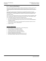
7
Right‐click the ILX34‐AENWG adapter and select PROPERTIES. Click the CONNECTION tab. Notice that the Status message at the bottom left corner of the dialog box reads "FAULTED". The module is faulted because, even though you set up the adapter's POINT I/O chassis size to the actual number of modules, plus the adapter, the adapter still remembers the size of 1 (the factory default value) until you reset this size manually. Note: You must be online to the adapter to change this setting.
ProSoft Technology, Inc. September 19, 2011 Page 47 of 209 Configure the ILX34-AENWG
User Manual
8
ILX34-AENWG ♦ Point I/O Platform
Wireless POINT I/O Adapter
Click the CHASSIS SIZE tab. 9
Click the SET CHASSIS SIZE IN MODULE button. Remember to inhibit and uninhibit the module for this to take effect. Now you can put your controller in Run mode, and the connection should be successful. Important: The information found in Controller Tag Reference (page 133) is also available in the
RSLogix 5000 online help file. Use the Help file search function under the 1734 catalog number
that you are configuring and select the Module Defined Data Types option. You see all of the
configurable parameters and associated values.
Page 48 of 209 ProSoft Technology, Inc. September 19, 2011 ILX34-AENWG ♦ Point I/O Platform
Wireless POINT I/O Adapter
2.6
Configure the ILX34-AENWG
User Manual
Configuring Wireless Settings in RSLogix 5000
Important: RSLogix 5000 does not save the Wireless Settings inside the project file. The Wireless
Settings and Wireless Statistics tabs are populated only when the processor is online to the ILX34AENWG.
Note: Allow sufficient time (30 to 60 seconds) for RSLogix 5000 to send and receive wireless
settings from the ILX34-AENWG.
Field
Description
Encryption Type Choose the method by which the adapter will apply encryption security:
NONE (not recommended)
WEP128 ‐ Legacy security setting using a 128‐bit key and WEP encryption.
WPA2/AES (Preferred) ‐ Security setting using WPA (pre‐shared key) authentication and AES encryption. The preferred encryption type is AES (Advanced Encryption Standard). You should only select WEP (wired equivalency protocol) for use with an older client radio that only has WEP encryption. WEP is the original security protocol used by 802.11 networks, but AES offers better protection against attacks, for several reasons: AES uses an advanced encryption algorithm that is not susceptible to the same weaknesses as WEP, it performs dynamic key management by changing the session keys frequently, and it performs message integrity checks to prevent forgery and replay. You can also select WEP 128, or None (no encryption) as the encryption type, but none of these settings are recommended. SSID Assign a network name (SSID) of up to 32 characters. The radio uses this name in all network references. All radios in a network must have the same SSID. SSID names are case‐sensitive. ProSoft Technology, Inc. September 19, 2011 Page 49 of 209 Configure the ILX34-AENWG
User Manual
ILX34-AENWG ♦ Point I/O Platform
Wireless POINT I/O Adapter
Field
Description
WPA Passphrase To use WPA2/AES encryption on packets sent between the radios, enter a WPA2/AES pass phrase of between eight and 63 normal keyboard characters. This phrase automatically generates an encryption key of 128 hexadecimal characters. This field is only available if you select WPA2/AES as the encryption type. Transmit Data Rate The recommended The ILX34‐AENWG supports the following transmit data rates. The default value is Auto: Max 54 Mbps, and this is the recommended value for most applications. 1 Mbps Auto: Max. 1 Mbps 2 Mbps Auto: Max. 2 Mbps 5.5 Mbps Auto: Max. 5.5 Mbps 11 Mbps Auto: Max. 11 Mbps 18 Mbps Auto: Max. 18 Mbps 24 Mbps Auto: Max. 24 Mbps 36 Mbps Auto: Max. 36 Mbps 54 Mbps Auto: Max. 54 Mbps WEP Key Index If using WEP128 encryption, select the Key Index that matches the Key Index used in the Access Point. WEP Keys (1‐4) If using WEP128 encryption, enter the WEP Keys that match the Keys in the Access Point. 2.7
Install the Antenna
All antennas for radios communicating directly with each other should be mounted so they are within line‐of‐sight and have the same antenna polarity (page 188). Antennas with a reverse polarity SMA connector can be mounted directly on the radio. Screw the antenna onto the antenna port connector until snug. Antennas that do not have a reverse polarity SMA connector must be mounted separately and connected to the radio using a ProSoft RadioLinx adaptor cable. Because the antenna cable attenuates the RF signal, to ensure optimum performance, use an antenna cable no longer than necessary. Note: The use of any antenna that is not on the ProSoft Technology approved antennas list may
result in radio transmissions that violate your country's wireless regulatory laws, which may lead to
civil liabilities or criminal penalties. Contact ProSoft Technology with any questions regarding
antenna selection.
Page 50 of 209 ProSoft Technology, Inc. September 19, 2011 ILX34-AENWG ♦ Point I/O Platform
Wireless POINT I/O Adapter
2.8
Configure the ILX34-AENWG
User Manual
Test the Network Installation Plan
Test proposed installations before the installation is finalized. After the network has been configured (page 32) and the radios have been configured (page 19):
install the ILX34‐AENWG radio in its proposed permanent location (page 19) cable the Configuration PC to the ILX34‐AENWG place the Access Point and Repeater radios in their proposed locations temporarily place each radio’s antenna near its proposed mounting location. The temporary placement of the antenna can be by hand, however, with this testing method, one person must hold the antenna while another monitors the Remote radio’s signal strength (page 94) as displayed on the Configuration PC. To improve the signal quality of each Remote’s communication:
increase the height of the antenna’s placement use higher‐gain antennas increase the radio’s transmission power, cable the radio to the Configuration PC, and reconfigure it (page 34) select a new location for the Remote radio and/or its antenna decrease the length of antenna cable determine and resolve sources of "electrical" noise which may be interfering with the radio transmission add a repeater (page 21) between the radios that are not communicating or reconfigure an existing radio as a repeater if line of sight is available ProSoft Technology, Inc. September 19, 2011 Page 51 of 209 Configure the ILX34-AENWG
User Manual
ILX34-AENWG ♦ Point I/O Platform
Wireless POINT I/O Adapter
Page 52 of 209 ProSoft Technology, Inc. September 19, 2011 ILX34-AENWG ♦ Point I/O Platform
Wireless POINT I/O Adapter
3
About the Example Applications
User Manual
About the Example Applications
In This Chapter
Support of Rack‐optimized and Direct Connections .......................................... 54
System Components.......................................................................................... 55
Set Up the Hardware ......................................................................................... 56
Example 1 ‐ Direct Connection and Rack Optimization ..................................... 57
Example 2 ‐ Direct Connection .......................................................................... 67 The following topics describe two example applications that demonstrate the procedures for configuring and communicating with POINT I/O modules using the ILX34‐AENWG adapter. Use these example applications as building blocks to help you get your own system up and running. We recommend that you set up and run the example applications and use them as guides. The following illustration shows the type of system you will be setting up. Note: During the installation, you must connect to the ILX34-AENWG directly via Ethernet to set its
wireless settings so it can communicate with its Access Point. To prevent a loop from occurring,
avoid connecting Ethernet cables to the Access Point and the ILX34-AENWG at the same time
after the wireless link is established.
ProSoft Technology, Inc. September 19, 2011 Page 53 of 209 About the Example Applications
User Manual
3.1
ILX34-AENWG ♦ Point I/O Platform
Wireless POINT I/O Adapter
Support of Rack-optimized and Direct Connections
The ILX34‐AENWG adapter supports both direct and rack‐optimized connections. A direct connection is a real‐time data transfer link between the controller and whatever module occupies the slot that the configuration data references.
Direct connection messaging occurs at a cyclic rate specified by the RPI during configuration. A rack‐optimized connection is a grouping of data from more than one I/O module into a single block of data sent over a single connection at the same data rate. Rack‐optimized connections reduce the total number of connections needed to transfer data when using many I/O modules in a system. The following example illustrates the benefit of rack‐
optimized connections. For example, a system contains 8 digital I/O modules interfaced to a ILX34‐AENWG adapter. If you use direct connections to transfer data to each of these I/O modules, you need 8 connections to transfer all of the data, one to each of the 8 I/O modules. If you use a rack‐
optimized connection to transfer the data, you only need a single connection ‐ the connection to the ILX34‐AENWG adapter. Important: Although rack-optimized connections offer an efficient way to use resources, there are
a few limitations on their use:
You can use only rack-optimized connections to send data to and from digital I/O modules.
Analog or specialty I/O requires direct connections.
All data is sent at the same time as the RPI rate of the ILX34-AENWG adapter.
Refer to the Rockwell Automation publication EtherNet/IP Performance and Application Guide,
publication number ENET-AP001, for more information on connections.
3.1.1 Mix Rack-optimized and Direct Connections
You can mix communication formats for different I/O modules communicating through the same adapter. I/O modules set up to use rack optimization communicate at the rate of the RPI configured for the ILX34‐AENWG adapter. I/O modules configured for direct communication communicate at their own set RPIs and ignore the ILX34‐AENWG adapter's RPI. Page 54 of 209 ProSoft Technology, Inc. September 19, 2011 ILX34-AENWG ♦ Point I/O Platform
Wireless POINT I/O Adapter
3.2
About the Example Applications
User Manual
System Components
We used the following components for the example applications. You need the same or similar components to set up your own control system using POINT I/O modules on an EtherNet/IP network. Quantity
Product Name
Catalog Number
Hardware
1 Wireless POINT I/O Adapter ILX34‐AENWG 1 POINT I/O 24V dc sink output module 1734‐OV4E/C 1 POINT I/O relay output module 1734‐OW2/C 1 DIN rail 199‐DR1 or equivalent 1 ControlLogix chassis 1756‐A4, (or 1756‐A7, 1756‐A13,1756‐A17) 1 ControlLogix power supply 1756‐PA72, (or 1756‐PB72) 1 ControlLogix controller 1756‐L5* with firmware version 17 1 ControlLogix EtherNet/IP bridge module 1756‐ENBT with firmware version 4.007 or higher 1 RadioLinx Industrial Hotspot RLXIB‐IHW 1 Personal computer that supports RSLogix 5000 software Any appropriate model running Windows NT 4.0, Service Pack 6A or higher 1 Ethernet switch Refer to manufacturer's specifications 1 24V dc power supply Associated media and connectors as needed Software
1 RSLinx communications software, version 2.54.00 or later 9355‐WAB, 9355‐WABOEM, 9355‐WABC 1 RSLogix 5000 programming software, version 17 or later 9324‐RLD300ENE ProSoft Technology, Inc. September 19, 2011 Page 55 of 209 About the Example Applications
User Manual
3.3
ILX34-AENWG ♦ Point I/O Platform
Wireless POINT I/O Adapter
Set Up the Hardware
In these examples, a ControlLogix chassis contains the Logix controller in slot 0, and a 1756‐ENBT bridge module in slot 3. We mounted the ILX34‐AENWG adapter on a DIN rail in slot 0, with a 1734‐OW2/C relay output module in slot 1, a 1734‐OV4E/C sink output module in slot 2, and a 24 volt DC power supply. To work along with this example, set up your system as follows.
Note that the example application, the Logix controller and 1756‐ENBT module (firmware revision 4.007 or later) uses the slots shown in the illustration (page 53). Verify the IP addresses for your programming terminal, 1756‐ENBT module, and ILX34‐
AENWG adapter. Verify the position (slot) of the I/O modules on the DIN rail. Verify that you have properly connected all wiring and cabling. You must configure your communication driver (such as AB_ETH‐1 or AB‐ETHIP‐1) in RSLinx software, as described in Configure the RSLinx Ethernet Communication Driver. Page 56 of 209 ProSoft Technology, Inc. September 19, 2011 ILX34-AENWG ♦ Point I/O Platform
Wireless POINT I/O Adapter
3.4
About the Example Applications
User Manual
Example 1 - Direct Connection and Rack Optimization
This example configures your ILX34‐AENWG for both direct connection and rack optimization using RSLogix 5000 software. You can mix communication formats for different I/O modules communicating through the same adapter.
I/O modules set up to use rack optimization communicate at the rate of the RPI configured for the ILX34‐AENWG adapter. I/O modules configured for direct communication communicate at their own set RPI and ignore the ILX34‐AENWG adapter RPI. Attention: You must use series C POINT I/O modules with the ILX34-AENWG adapter. Series A
or B POINT I/O modules will not work with this adapter.
3.4.1 Add the Relay Output Module and Configure for Direct
Connection
1
Right‐click the ILX34‐AENWG adapter under the I/O Configuration folder and select NEW MODULE. 2
In the SELECT MODULE dialog box, choose the 1734‐OW2 relay output module from the list, and click OK. ProSoft Technology, Inc. September 19, 2011 Page 57 of 209 About the Example Applications
User Manual
3
ILX34-AENWG ♦ Point I/O Platform
Wireless POINT I/O Adapter
In the MODULE PROPERTIES dialog, enter the following information: a) Name b) Slot In the Module Definition area, click the CHANGE ... button, and change the Connection type from Rack Optimization (default) to DATA. Page 58 of 209 ProSoft Technology, Inc. September 19, 2011 ILX34-AENWG ♦ Point I/O Platform
Wireless POINT I/O Adapter
4
About the Example Applications
User Manual
Click the CONNECTION tab, and then change the RPI value for the module from 20 (the default) to 50 (the recommended value for analog or specialty modules). This value determines how often to exchange data with the ILX34‐AENWG adapter. Important: To avoid overloading the ILX34-AENWG adapter, we recommend that RPI be no less
than 10 ms for rack connections and 50 ms for direct connections.
5
Click OK save the configuration. The following illustration shows the I/O Configuration for this project. ProSoft Technology, Inc. September 19, 2011 Page 59 of 209 About the Example Applications
User Manual
ILX34-AENWG ♦ Point I/O Platform
Wireless POINT I/O Adapter
3.4.2 Add the Digital Output Module and Configure for Rack
Optimization
1
Right‐click the ILX34‐AENWG adapter under the I/O Configuration folder and select NEW MODULE. 2
In the SELECT MODULE dialog box, choose the 1734‐OV4E digital output module from the list, and click OK. Page 60 of 209 ProSoft Technology, Inc. September 19, 2011 ILX34-AENWG ♦ Point I/O Platform
Wireless POINT I/O Adapter
3
About the Example Applications
User Manual
In the MODULE PROPERTIES dialog, enter the following information: a) Name b) Slot In the MODULE DEFINITION area of the dialog box, notice that the default Connection type is RACK OPTIMIZATION. 4
Click the CONNECTION tab, and then change the RPI value for the module from 20 (the default) to 10 (the recommended value for digital modules). This value determines how often to exchange data with the ILX34‐AENWG adapter. Important: To avoid overloading the ILX34-AENWG adapter, we recommend that RPI be no less
than 10 ms for rack connections and 50 ms for direct connections.
ProSoft Technology, Inc. September 19, 2011 Page 61 of 209 About the Example Applications
User Manual
5
ILX34-AENWG ♦ Point I/O Platform
Wireless POINT I/O Adapter
Click OK save the configuration. The following illustration shows the I/O Configuration for this project. 3.4.3 Downloading the Sample Program to the Processor
Note: The key switch on the front of the ControlLogix processor must be in the REM or PROG
position.
1
2
If you are not already online with the processor, open the Communications menu, and then choose DOWNLOAD. RSLogix 5000 will establish communication with the processor. You do not have to download through the processor's serial port, as shown here. You may download through any available network connection. When communication is established, RSLogix 5000 will open a confirmation dialog box. Click the DOWNLOAD button to transfer the sample program to the processor. 3
4
RSLogix 5000 will compile the program and transfer it to the processor. This process may take a few minutes. When the download is complete, RSLogix 5000 will open another confirmation dialog box. If the key switch is in the REM position, click OK to switch the processor from PROGRAM mode to RUN mode. Note: If you receive an error message during these steps, refer to your RSLogix documentation to
interpret and correct the error.
Page 62 of 209 ProSoft Technology, Inc. September 19, 2011 ILX34-AENWG ♦ Point I/O Platform
Wireless POINT I/O Adapter
About the Example Applications
User Manual
3.4.4 Verify the Chassis Size
You must configure the chassis size for the ILX34‐AENWG before you can make any I/O connections (page 43). The default setting for the chassis size is 1 slot, which represents the adapter by itself. When the adapter's non‐volatile chassis size does not match the actual number of modules present on its backplane, the adapter does not make any I/O connections and an error occurs, as shown in the MODULE PROPERTIES dialog box. This procedure synchronizes the chassis size value from the RSLogix 5000 software into the ILX34‐AENWG hardware. You must be online to perform this procedure. 1
2
3
Verify that RSLogix 5000 software is online to the processor. Double‐click the ILX34‐AENWG adapter under I/O CONFIGURATION in the CONTROLLER ORGANIZATION window. This action opens the MODULE PROPERTIES dialog box. On the MODULE PROPERTIES dialog box, click the CONNECTION tab. Notice that the MODULE FAULT area of the dialog box contains information about the error code. ProSoft Technology, Inc. September 19, 2011 Page 63 of 209 About the Example Applications
User Manual
4
ILX34-AENWG ♦ Point I/O Platform
Wireless POINT I/O Adapter
Click the CHASSIS SIZE tab, and then click the CLICK SET CHASSIS SIZE IN MODULE button. 5
This action opens a notification dialog box. Take any necessary steps to prevent hazardous conditions, and then click OK to dismiss the dialog box. Page 64 of 209 ProSoft Technology, Inc. September 19, 2011 ILX34-AENWG ♦ Point I/O Platform
Wireless POINT I/O Adapter
6
About the Example Applications
User Manual
Notice the chassis size in the module has been updated to match the hardware configuration. 7
Click OK to dismiss the Module Properties dialog box. At this point, your POINTBus status LED should be solid green. All the yellow triangles in your I/O configuration should be gone. 8
Open the FILE menu, and then click SAVE to save the project. ProSoft Technology, Inc. September 19, 2011 Page 65 of 209 About the Example Applications
User Manual
ILX34-AENWG ♦ Point I/O Platform
Wireless POINT I/O Adapter
3.4.5 View Module Data
You can view module data and communication status in the controller tags in RSLogix 5000. The following illustration shows the ILX34‐AENWG configured with the sample application.
POINT_IO_Adapter = the name you gave to your Ethernet adapter # = slot number of POINT I/O module C = configuration, I = input, O = output Use the controller tags in your ladder program to read input data or write output data.
Slot Status Bits: The Slot Status bits display the connection status for each of the POINT I/O modules that use a rack‐optimized connection. Bit 0 is reserved for the adapter and always reports a value of 1. Each of the other bits (1 to 63) correspond to a POINT I/O module that you install in the POINT I/O backplane. In this example, we configured the ILX34‐AENWG adapter for both rack‐optimized and direct connections. The slot status bits indicate that the module in slot 2 is operating correctly: o 0=module participating with no errors and o 1=module not participating or connection error (typically, module removed/missing) Page 66 of 209 ProSoft Technology, Inc. September 19, 2011 ILX34-AENWG ♦ Point I/O Platform
Wireless POINT I/O Adapter
3.5
About the Example Applications
User Manual
Example 2 - Direct Connection
In this example, a ControlLogix controller communicates with POINT I/O modules via the ILX34‐
AENWG adapter using a direct connection. The adapter makes a direct connection to each of the modules referenced by the data. Attention: You must use series C POINT I/O modules with the ILX34-AENWG adapter. Series A
or B POINT I/O modules will not work with this adapter.
3.5.1 Add the Relay Output Module and Configure for Direct
Connection
1
Right‐click the ILX34‐AENWG adapter under the I/O Configuration folder and select NEW MODULE. 2
In the SELECT MODULE dialog box, choose the 1734‐OW2 relay output module from the list, and click OK. ProSoft Technology, Inc. September 19, 2011 Page 67 of 209 About the Example Applications
User Manual
3
ILX34-AENWG ♦ Point I/O Platform
Wireless POINT I/O Adapter
In the MODULE PROPERTIES dialog, enter the following information: a) Name b) Slot In the Module Definition area, click the CHANGE ... button, and change the Connection type from Rack Optimization (default) to DATA. Page 68 of 209 ProSoft Technology, Inc. September 19, 2011 ILX34-AENWG ♦ Point I/O Platform
Wireless POINT I/O Adapter
4
About the Example Applications
User Manual
Click the CONNECTION tab, and then change the RPI value for the module from 20 (the default) to 50 (the recommended value for analog or specialty modules). This value determines how often to exchange data with the ILX34‐AENWG adapter. Important: To avoid overloading the ILX34-AENWG adapter, we recommend that RPI be no less
than 10 ms for rack connections and 50 ms for direct connections.
5
Click OK save the configuration. The following illustration shows the I/O Configuration for this project. ProSoft Technology, Inc. September 19, 2011 Page 69 of 209 About the Example Applications
User Manual
ILX34-AENWG ♦ Point I/O Platform
Wireless POINT I/O Adapter
3.5.2 Add the Digital Output Module and Configure for Direct
Connection
1
Right‐click the ILX34‐AENWG adapter under the I/O Configuration folder and select NEW MODULE. 2
In the SELECT MODULE dialog box, choose the 1734‐OV4E digital output module from the list, and click OK. Page 70 of 209 ProSoft Technology, Inc. September 19, 2011 ILX34-AENWG ♦ Point I/O Platform
Wireless POINT I/O Adapter
3
About the Example Applications
User Manual
In the MODULE PROPERTIES dialog, enter the following information: a) Name b) Slot In the Module Definition area, click the CHANGE ... button, and change the Connection type from Rack Optimization (default) to DATA. ProSoft Technology, Inc. September 19, 2011 Page 71 of 209 About the Example Applications
User Manual
4
ILX34-AENWG ♦ Point I/O Platform
Wireless POINT I/O Adapter
Click the CONNECTION tab, and then change the RPI value for the module from 20 (the default) to 10 (the recommended value for digital modules). This value determines how often to exchange data with the ILX34‐AENWG adapter. 5
Click OK save the configuration. The following illustration shows the I/O Configuration for this project. Page 72 of 209 ProSoft Technology, Inc. September 19, 2011 ILX34-AENWG ♦ Point I/O Platform
Wireless POINT I/O Adapter
About the Example Applications
User Manual
3.5.3 Edit the Controller Tags
When you add modules to the I/O configuration, the system creates tags for those modules to use in the application program. For the example application, you need to add one more controller tag. 1
Double‐click the CONTROLLER TAGS folder in the project dialog. The action opens the CONTROLLER TAGS dialog box. You will see the tags created for the ILX34‐
AENWG adapter and digital I/O modules. 2
Click the Edit Tags tab at the bottom of the Controller Tags dialog. 3
Create the following tag: Tag
Type
Parts_Count Counter 4
Close the Controller Tags dialog. ProSoft Technology, Inc. September 19, 2011 Page 73 of 209 About the Example Applications
User Manual
ILX34-AENWG ♦ Point I/O Platform
Wireless POINT I/O Adapter
3.5.4 Create the Ladder Program
Next, create the example ladder program to test the I/O. 1
Double‐click MAIN ROUTINE under the Main Program folder. 2
Enter the following ladder program using the tags previously created. 3
Save the program. Page 74 of 209 ProSoft Technology, Inc. September 19, 2011 ILX34-AENWG ♦ Point I/O Platform
Wireless POINT I/O Adapter
About the Example Applications
User Manual
3.5.5 Downloading the Sample Program to the Processor
Note: The key switch on the front of the ControlLogix processor must be in the REM or PROG
position.
1
2
If you are not already online with the processor, open the Communications menu, and then choose DOWNLOAD. RSLogix 5000 will establish communication with the processor. You do not have to download through the processor's serial port, as shown here. You may download through any available network connection. When communication is established, RSLogix 5000 will open a confirmation dialog box. Click the DOWNLOAD button to transfer the sample program to the processor. 3
4
RSLogix 5000 will compile the program and transfer it to the processor. This process may take a few minutes. When the download is complete, RSLogix 5000 will open another confirmation dialog box. If the key switch is in the REM position, click OK to switch the processor from PROGRAM mode to RUN mode. Note: If you receive an error message during these steps, refer to your RSLogix documentation to
interpret and correct the error.
ProSoft Technology, Inc. September 19, 2011 Page 75 of 209 About the Example Applications
User Manual
ILX34-AENWG ♦ Point I/O Platform
Wireless POINT I/O Adapter
3.5.6 Verify the Chassis Size
You must configure the chassis size for the ILX34‐AENWG before you can make any I/O connections (page 43). The default setting for the chassis size is 1 slot, which represents the adapter by itself. When the adapter's non‐volatile chassis size does not match the actual number of modules present on its backplane, the adapter does not make any I/O connections and an error occurs, as shown in the MODULE PROPERTIES dialog box. This procedure synchronizes the chassis size value from the RSLogix 5000 software into the ILX34‐AENWG hardware. You must be online to perform this procedure. 1
2
3
Verify that RSLogix 5000 software is online to the processor. Double‐click the ILX34‐AENWG adapter under I/O CONFIGURATION in the CONTROLLER ORGANIZATION window. This action opens the MODULE PROPERTIES dialog box. On the MODULE PROPERTIES dialog box, click the CONNECTION tab. Notice that the MODULE FAULT area of the dialog box contains information about the error code. Page 76 of 209 ProSoft Technology, Inc. September 19, 2011 ILX34-AENWG ♦ Point I/O Platform
Wireless POINT I/O Adapter
4
About the Example Applications
User Manual
Click the CHASSIS SIZE tab, and then click the CLICK SET CHASSIS SIZE IN MODULE button. 5
This action opens a notification dialog box. Take any necessary steps to prevent hazardous conditions, and then click OK to dismiss the dialog box. ProSoft Technology, Inc. September 19, 2011 Page 77 of 209 About the Example Applications
User Manual
6
ILX34-AENWG ♦ Point I/O Platform
Wireless POINT I/O Adapter
Notice the chassis size in the module has been updated to match the hardware configuration. 7
Click OK to dismiss the Module Properties dialog box. At this point, your POINTBus status LED should be solid green. All the yellow triangles in your I/O configuration should be gone. 8
Open the FILE menu, and then click SAVE to save the project. Page 78 of 209 ProSoft Technology, Inc. September 19, 2011 ILX34-AENWG ♦ Point I/O Platform
Wireless POINT I/O Adapter
About the Example Applications
User Manual
3.5.7 View Module Data
You can view module data and communication status in the controller tags in RSLogix 5000. The following illustration shows the ILX34‐AENWG configured with the sample application.
ILX34_AENWG = the name you gave to your Ethernet adapter # = slot number of POINT I/O module C = configuration, I = input, O = output Use the controller tags in your ladder program to read input data or write output data.
Slot Status Bits: The Slot Status bits display the connection status for each of the POINT I/O modules that use a rack‐optimized connection. Bit 0 is reserved for the adapter and always reports a value of 1. Each of the other bits (1 to 63) correspond to a POINT I/O module that you install in the POINT I/O backplane. In this example, we configured the ILX34‐AENWG adapter for both rack‐optimized and direct connections. The slot status bits indicate that the module in slot 2 is operating correctly: o 0=module participating with no errors and o 1=module not participating or connection error (typically, module removed/missing) ProSoft Technology, Inc. September 19, 2011 Page 79 of 209 About the Example Applications
User Manual
ILX34-AENWG ♦ Point I/O Platform
Wireless POINT I/O Adapter
Page 80 of 209 ProSoft Technology, Inc. September 19, 2011 ILX34-AENWG ♦ Point I/O Platform
Wireless POINT I/O Adapter
4
Diagnostics and Troubleshooting
User Manual
Diagnostics and Troubleshooting
In This Chapter
Connect to the Adapter's Web Page ................................................................. 82
Viewing Wireless Statistics in RSLogix 5000 .................................................... 105
Establish I/O Connections ............................................................................... 107
Recover From an Overloaded Adapter ............................................................ 107
Empty Slots and RIUP Situations ..................................................................... 108
LED Status Indicators ....................................................................................... 109
Check the Ethernet cable ................................................................................ 112
Restoring the Factory Default Network Settings ............................................. 114
Restoring the All Factory Default Settings ....................................................... 116
Installing a Replacement Wireless POINT I/O Adapter to an Existing System . 117
Upgrading to Firmware Version 3.5.0 ............................................................. 118 Diagnostics values are available through the following user interfaces:
Web Interface (page 83) RSLogix 5000 (page 105) EtherNet/IP Object (page 184) ProSoft Technology, Inc. September 19, 2011 Page 81 of 209 Diagnostics and Troubleshooting
User Manual
4.1
ILX34-AENWG ♦ Point I/O Platform
Wireless POINT I/O Adapter
Connect to the Adapter's Web Page
Open your web browser (for example, Microsoft Internet Explorer or Firefox), and connect to the adapter's temporary network address. http://192.168.1.xxx (where xxx is the value you entered in the rotary switches on the front of the adapter.) Important: Your PC must be on the same TCP/IP subnet as the adaptor to view these pages.
Important: You must prefix the numeric IP address with "http://", otherwise the web browser
may not be able to interpret the address.
The adapter's home page consists of a tree view in the left pane for navigation, and an information pane in the middle. The right column contains links for additional resources and information.
To view the contents of a folder, click the EXPAND button. To select a page to view, click the page title in the tree view. If you are unable to connect to the adapter's web page, verify that your PC is correctly configured to reach IP addresses on the subnet where your adapter communicates. Page 82 of 209 ProSoft Technology, Inc. September 19, 2011 ILX34-AENWG ♦ Point I/O Platform
Wireless POINT I/O Adapter
Diagnostics and Troubleshooting
User Manual
4.1.1 Diagnostics Pages
The DIAGNOSTICS pages show you current operational information about your POINT I/O adapter and connected devices. Select the DIAGNOSTICS folder in the tree view on the left side of the page, and click EXPAND to view the menu, or click the tabs at the top of the page. The Diagnostics pages automatically refresh at 15 second intervals. To change the refresh interval, enter a value in seconds in the REFRESH RATE (SEC) field at the top of the page. Diagnostic Overview Page
The DIAGNOSTIC OVERVIEW page opens when you select the DIAGNOSTICS folder in the menu on the left side of the page. Use this page to view the ILX34‐AENWG adapter's current configuration and status. ProSoft Technology, Inc. September 19, 2011 Page 83 of 209 Diagnostics and Troubleshooting
User Manual
ILX34-AENWG ♦ Point I/O Platform
Wireless POINT I/O Adapter
Ring Status
Field
Description
Network Topology Reserved for future use. This value will always be "Linear" Network Status Reserved for future use. This value will always be "Normal" Ring Supervisor Reserved for future use. This value will always be zeros for the MAC Address and IP Address. System Resource Utilization
Field
Description
CPU Utilization Indicates the percentage of the time the adaptor's CPU (Central Processing Unit) is working. Peak CPU utilization is shown in parentheses. Module Uptime The amount of time the adaptor has been powered up and operating, since the last power cycle. CIP Connection Statistics
Field
Description
Current CIP Msg Connections The number of CIP Msg connections that are currently open. In most cases, CIP messages are issued for diagnostic purposes from ladder logic, and not for regular Input and Output data. CIP Msg Connection Limit The ILX34‐AENWG can support up to 32 CIP Msg connections. Max Msg Connections Observed The maximum number of CIP Msg connections that have occurred at one time since the unit was reset. Current CIP I/O Connections The number of I/O connections that are currently open. Note that several I/O slices can be Rack Optimized into a single connection. If this number matches the number of connections expected, the unit is fully operational. CIP I/O Connection Limit The ILX34‐AENWG can support up to 20 connections. Although up to 63 I/O modules can be connected to the ILX34, these must be rack optimized to fit into the limit of 20 connections. Max I/O Connections Observed The maximum number of connections that have occurred at one time since the unit was reset. Conn Opens Number of times that an I/O (or possibly a Msg) connection open request has been received from the controller. Open Errors Number of times that there has been an error in establishing the I/O connection when the open request has been received. Conn Closes Number of times the connection has been closed. This value can indicate a problem in the RF traffic that has caused a timeout, causing the connection to close. Close Errors Number of times an error has occurred when the controller is attempting to close a connection. These errors can be caused by a timeout, because a loss of communication could prevent all of the packets that would normally occur during a close to be transferred in a timely manner. Page 84 of 209 ProSoft Technology, Inc. September 19, 2011 ILX34-AENWG ♦ Point I/O Platform
Wireless POINT I/O Adapter
Diagnostics and Troubleshooting
User Manual
Field
Description
Conn Timeouts Timeouts occur when the controller does not receive packets from an I/O connection within the RPI requirements. The timeout occurs within 4 x RPI value. If the controller has not heard from the I/O in 4 RPI times, it times out. The minimum timeout value is 100ms. Therefore, even if the RPI is 4ms, a timeout will not occur until no packets have been heard from the I/O in over 100ms. If the number of timeouts is high, the network traffic is likely too high.
LED Status:
Field
Description
Module Status Flashing red = an error condition Solid green = functioning properly Network Activity Rapidly flashing green = successful data transfer activity Slowly flashing green = an issue or difficulty within the network Flashing red = an error condition Network Status Flashing green = an error condition Solid green = functioning properly Point Bus Status Flashing red = an error condition Solid green = functioning properly Module Settings
Field
Description
Chassis Size Displays the chassis size that is stored in the adapter. (page 63) Switches Displays the configuration of the thumbwheel switches on the face of the ILX34‐AENWG adapter (page 25) ProSoft Technology, Inc. September 19, 2011 Page 85 of 209 Diagnostics and Troubleshooting
User Manual
ILX34-AENWG ♦ Point I/O Platform
Wireless POINT I/O Adapter
Network Settings Page
The NETWORK SETTINGS page opens when you expand the DIAGNOSTICS folder, and then click the NETWORK SETTINGS link on the left side of the page. Use this page to view configuration and status information for the Ethernet and Antenna ports on the ILX34‐AENWG. Note: The values on this page are for information only, and cannot be modified. To change these
values, use the Network Configuration Page (page 98).
Page 86 of 209 ProSoft Technology, Inc. September 19, 2011 ILX34-AENWG ♦ Point I/O Platform
Wireless POINT I/O Adapter
Diagnostics and Troubleshooting
User Manual
Network Interface
Field
Description
Ethernet Address (MAC) The MAC address (hexadecimal) of the ILX34‐AENWG adapter IP Address The IP address identifies each node on the IP network (or system of connected networks). Each TCP/IP node on a network (including the Ethernet module) must have a unique IP address. Subnet Mask Subnet mask for the host interface. Allows communication with a subnet behind the host interface. Default Gateway The IP address of a network router where data is sent if the destination IP address is outside the local subnet. The gateway is the device that routes the traffic from the local area network to other networks such as the Internet. Primary Name Server The IP address of the primary DNS server to use for resolving (or translating) names to IP addresses Secondary Name Server The IP address of the secondary DNS server to use for resolving (or translating) names to IP addresses Default Domain Name A name that identifies one or more IP addresses Host Name The Fully Qualified Domain Name (FQDN) Name Resolution Indicates if DNS is enabled or disabled. Ethernet Interface Configuration
Field
Description
Obtain Network Configuration Static or Dynamic Ethernet Port 1 / 2
Ethernet Port 1 is an internal connection to the Wireless port. These statistics will not change and do not reflect the status of the wireless connection. Field
Description
Interface State Enabled or Disabled. Any other condition indicates a problem. Link Status Active or Inactive. Port 1 will always display "Active". Media Speed 10 megabits or 100 megabits Duplex Half Duplex or Full Duplex Autonegotiation Status Autonegotiate Speed and Duplex, or Force Speed and Duplex ProSoft Technology, Inc. September 19, 2011 Page 87 of 209 Diagnostics and Troubleshooting
User Manual
ILX34-AENWG ♦ Point I/O Platform
Wireless POINT I/O Adapter
Ethernet Statistics Page
The ETHERNET STATISTICS page opens when you expand the DIAGNOSTICS folder, and then click the ETHERNET STATISTICS link on the left side of the page. Use this page to view detailed status information for the Ethernet and Antenna ports on the ILX34‐AENWG. Note: The values on this page are for information only, and cannot be modified. To change these
values, use the Network Configuration Page (page 98).
Page 88 of 209 ProSoft Technology, Inc. September 19, 2011 ILX34-AENWG ♦ Point I/O Platform
Wireless POINT I/O Adapter
Diagnostics and Troubleshooting
User Manual
Ethernet Port 1 / 2
Ethernet Port 1 is an internal connection to the Wireless port. These statistics will not change and do not reflect the status of the wireless connection. Field
Description
Interface State Enabled or Disabled. Any other condition indicates a problem. Link Status Active or Inactive. Port 1 will always display "Active". Media Speed 10 megabits or 100 megabits Duplex Half Duplex or Full Duplex Autonegotiation Status Autonegotiate Speed and Duplex, or Force Speed and Duplex Interface Counters
Field
Description
In Octets Number of octets (bytes) received In Ucast Packets Number of unicast packets received In NUcast Packets Number of broadcast and multicast packets received In Discards Number of received packets that have been discarded In Errors Number of packets received with CRC errors In Unknown Protos Number of packets received with unknown protocols Out Octets Number of octets (bytes) transmitted Out Ucast Packets Number of unicast packets transmitted Out NUcast Packets Number of broadcast and multicast packets transmitted Out Discards Number of sent packets that have been discarded Out Errors Number of packets sent with CRC errors Media Counters Port 1 / 2
Field
Description
Alignment Errors A count of frames received on a particular interface that are not an integral number of octets in length and do not pass the FCS check. Alignment Errors can result from MAC layer packet formation problems, cabling problems that cause corrupted or lost data, and packets that pass through more than two cascaded multiport transceivers. FCS Errors A count of frames received on a particular interface that are not an integral number of octets in length and do not pass the FCS check. FCS or Alignment Errors indicate bit errors during a transmission or reception. Single Collisions A count of successfully transmitted frames on a particular interface for which transmission is inhibited by exactly one collision. Multiple Collisions A count of successfully transmitted frames on a particular interface for which transmission is inhibited by more than one collision. SQE Test Errors A count of of times that the Signal Quality Error (SQE) TEST ERROR message is generated. The SQE Test is used to test for the collision present circuit between a transceiver and a network interface card (NIC). ProSoft Technology, Inc. September 19, 2011 Page 89 of 209 Diagnostics and Troubleshooting
User Manual
ILX34-AENWG ♦ Point I/O Platform
Wireless POINT I/O Adapter
Field
Description
Deferred Transmissions A count of frames for which the first transmission attempt on a particular interface is delayed because the medium is busy. Late Collisions Number of times that a collision is detected later than 512 bit‐times into the transmission of a packet Excessive Collisions Number of frames for which transmission fails due to excessive collisions MAC Transmit Errors A count of frames for which transmission on a particular interface fails due to an internal MAC sublayer transmit error. A faulty network transmitter can cause Internal MAC Transmit errors. Check the device to insure that it is functioning correctly. Carrier Sense Errors The number of times that the carrier sense condition was lost or never asserted when attempting to transmit a frame on a particular interface. Frame Too Long A count of frames received on a particular interface that exceed the maximum permitted framer size. MAC Receive Errors A count of frames for which reception on a particular interface fails due to an internal MAC sublayer receive error. Page 90 of 209 ProSoft Technology, Inc. September 19, 2011 ILX34-AENWG ♦ Point I/O Platform
Wireless POINT I/O Adapter
Diagnostics and Troubleshooting
User Manual
I/O Connections Page
The I/O CONNECTIONS page opens when you expand the DIAGNOSTICS folder, and then click the I/O CONNECTIONS link on the left side of the page. Use this page to view detailed status information for the Input and Output modules connected to the ILX34‐AENWG. Column
Description
Conn# / Uptime The connection assigned to this I/O connection and the amount of time that this connection has been up. Rcv/Xmt Receive and Transmit (Rcv/Xmt) Conn. ID Connection ID in hexidecimal Source Source IP Address with an indication of the following
(O) for originator
(T) for target Dest Destination IP Address Multicast Addr. Multicast Address RPI Requested Packet Interval (RPI) Lost/Slot Shows the number of lost packets and the slot number for the connection. A slot value of 0 indicates that this is a rack‐optimized connection. Size Size of data in bytes ProSoft Technology, Inc. September 19, 2011 Page 91 of 209 Diagnostics and Troubleshooting
User Manual
ILX34-AENWG ♦ Point I/O Platform
Wireless POINT I/O Adapter
Diagnostic Messaging Page
The DIAGNOSTIC MESSAGING page opens when you expand the DIAGNOSTICS folder, and then click the DIAGNOSTIC MESSAGING link on the left side of the page. Use this page to execute explicit, unconnected message services (page 181). Field
Description
Service Get Attribute Single or Get Attributes All I/O Module Slot Position 0 to 63 decimal Class (decimal) Refer to the documentation for each POINT I/O module for supported Class types Instance (decimal) Refer to the documentation for each POINT I/O module for supported Instance types Attribute (decimal) Refer to the documentation for each POINT I/O module for supported Attribute types Timeout (seconds) The number of seconds to wait for a response from the POINT I/O module Page 92 of 209 ProSoft Technology, Inc. September 19, 2011 ILX34-AENWG ♦ Point I/O Platform
Wireless POINT I/O Adapter
Diagnostics and Troubleshooting
User Manual
The following illustration shows the response to the CIP command "Get Attributes All", sent to the I/O module in Slot 1. The data is returned in hexadecimal format. Refer to the documentation for each POINT I/O module (page 195) to determine the meaning of the response. ProSoft Technology, Inc. September 19, 2011 Page 93 of 209 Diagnostics and Troubleshooting
User Manual
ILX34-AENWG ♦ Point I/O Platform
Wireless POINT I/O Adapter
Wireless Statistics Page
The WIRELESS STATISTICS page opens when you expand the DIAGNOSTICS folder, and then click the WIRELESS STATISTICS link on the left side of the page. Use this page to view configuration and status information for the Wireless port on the ILX34‐AENWG. Link Information
Field
Signal Strength Signal to Noise Description
The colored graph indicates the signal level (page 95).
< 0 , this is a BAD condition
< 10, this is an OK condition
> 10, this is a GOOD condition Radio Link Time The up‐link time in days:hours:minutes:seconds. Note: This link status is checked at the Refresh rate, once every 10 seconds by default. If the link is down for less time than this, the up‐
time for the link will not get reset to 0. Radio Parent MAC Data Rate The MAC address (hexadecimal) of the parent radio (access point) Rf rate of the last packet received by the ILX34‐AENWG. Although this field is informational, some packets, such as 802.11 management packets, will be at a rate that is lower than the data. In such an instance, the data could be going at a rate faster than this. Statistics
Field
Packets Received Successfully Description
Messages received with success. The average value gives a good indication of RF bandwidth consumption. The average should not exceed 1000 packets per second. If it does exceed this, the RPI should be decreased on the connections. Page 94 of 209 ProSoft Technology, Inc. September 19, 2011 ILX34-AENWG ♦ Point I/O Platform
Wireless POINT I/O Adapter
Field
Packets Transmitted Successfully Packet Transmit Failures Packet Transmit Retries Diagnostics and Troubleshooting
User Manual
Description
Messages sent with success. The average value gives a good indication of RF bandwidth consumption. The average should not exceed 500 packets per second. f it does exceed this, the RPI should be decreased on the connections. Messages that have been retried 8 times and still were not transferred successfully. This number should not exceed 1% of the Packets Transmitted successfully. Messages sent requiring a retry. Retries of 20 to 50 per second are not uncommon. Retries of several hundred per second indicate the RF network is too busy or the RF link is poor. Version
Field
Kernel Revision WIFI Module Firmware Description
The internal software revision for the POINT I/O adapter The internal software revision for the wireless component of the POINT I/O adapter Signal Strength Graph
Image
Signal Strength
Signal to Noise
‐90 dBm 0 dB ‐88 dBm 2 dB ‐86 dBm 4 dB ‐84 dBm 6 dB ‐82 dBm 8 dB ‐80 dBm 10 dB ‐78 dBm 12 dB ‐76 dBm 14 dB ‐74 dBm 16 dB ‐72 dBm 18 dB ‐70 dBm 20 dB ‐68 dBm 22 dB ‐66 dBm 24 dB ‐64 dBm 26 dB ‐62 dBm 28 dB ‐60 dBm or greater 30 dB ProSoft Technology, Inc. September 19, 2011 Page 95 of 209 Diagnostics and Troubleshooting
User Manual
ILX34-AENWG ♦ Point I/O Platform
Wireless POINT I/O Adapter
4.1.2 Configuration Pages
The CONFIGURATION pages allows you to view and edit configuration information for your ILX34‐
AENWG I/O adapter and connected devices. Select the CONFIGURATION folder in the tree view on the left side of the page, and click EXPAND to view the menu, or click the tabs at the top of the page. Important: The values on these pages are in non-volatile memory. Changes to these parameters
do not take effect until you reset or cycle power to the ILX34-AENWG adapter.
Some of the configuration pages require you to provide a user name and password.
The default user name is "admin". The default password is "password". The user name and password are case sensitive. Page 96 of 209 ProSoft Technology, Inc. September 19, 2011 ILX34-AENWG ♦ Point I/O Platform
Wireless POINT I/O Adapter
Diagnostics and Troubleshooting
User Manual
Identity Page
The IDENTITY page opens when you select the CONFIGURATION folder in the menu on the left side of the page, and then click the IDENTITY link. Use this page to view or modify the ILX34‐AENWG adapter's name, location and chassis size. Important: The values on this page are in non-volatile memory. Changes to these parameters do
not take effect until you reset or cycle power to the ILX34-AENWG adapter.
Field
Description
Host Name the name a Domain Name Server uses to resolve this adapter’s IP address Module Description (Optional) Type a description for the ILX34‐AENWG adapter. This can be useful to identify a specific ILX34‐AENWG at sites where multiple adapters may be deployed. Module Location (Optional) Type a location for the ILX34‐AENWG adapter. This can be useful to identify a specific ILX34‐AENWG at sites where multiple adapters may be deployed. Chassis Size The number of POINT I/O modules plus the adapter. This value must match the number of I/O modules plus one for the adapter before any I/O connections are allowed (page 63). ProSoft Technology, Inc. September 19, 2011 Page 97 of 209 Diagnostics and Troubleshooting
User Manual
ILX34-AENWG ♦ Point I/O Platform
Wireless POINT I/O Adapter
Network Configuration Page
The NETWORK page opens when you select the CONFIGURATION folder in the menu on the left side of the page, and then click the NETWORK link. Use this page to view or modify the ILX34‐AENWG adapter's TCP/IP and Ethernet port settings. Important: The values on this page are in non-volatile memory. Changes to these parameters do
not take effect until you reset or cycle power to the ILX34-AENWG adapter.
Page 98 of 209 ProSoft Technology, Inc. September 19, 2011 ILX34-AENWG ♦ Point I/O Platform
Wireless POINT I/O Adapter
Diagnostics and Troubleshooting
User Manual
Initial Network Configuration
Field
Description
Ethernet Interface Configuration Static ‐ uses a fixed IP address Dynamic DHCP ‐ obtains an IP address from a DHCP server Network Interface
Field
Description
IP Address The IP address identifies each node on the IP network (or system of connected networks). Each TCP/IP node on a network (including the Ethernet module) must have a unique IP address. This value must match the IP address entered on the General Tab of the Module Properties dialog box in RSLogix 5000. Subnet Mask Subnet addressing is an extension of the IP address scheme that lets a site use a single net ID for multiple physical networks. Routing outside of the site continues by dividing the IP address into a net ID and a host ID via the class. Inside a site, the subnet mask is used to redivide the IP address into a custom net ID portion and host ID portion. This field is set to 0.0.0.0 by default. Gateway Address A gateway connects individual physical networks into a system of networks. When a node needs to communicate with a node on another network, a gateway transfers the data between the two networks. The following figure shows gateway G connecting Network 1 with Network 2. Primary Name Server Enter the IP address of the primary DNS server to use for resolving (or translating) names to IP addresses Secondary Name Server Enter the IP address of the secondary DNS server to use for resolving (or translating) names to IP addresses Domain Name Domain (or domain zone) of which the ILX34‐AENWG is a part. This value is used during name resolutions if a fully qualified name is not provided, and also for DNS updates. Ethernet Link Port 1 / 2
Field
Description
Port x Enable Enable or Disable Autonegotiate Status Autonegotiate Speed and Duplex ‐ determine speed and duplex by negotiating with connected devices Force Speed and Duplex ‐ specify speed and duplex, setting must match configuration for other connected devices Select Port Speed 10 megabits, 100 megabits Select Duplex Mode Half Duplex, Full Duplex ProSoft Technology, Inc. September 19, 2011 Page 99 of 209 Diagnostics and Troubleshooting
User Manual
ILX34-AENWG ♦ Point I/O Platform
Wireless POINT I/O Adapter
Services Page
The SERVICES page opens when you select the CONFIGURATION folder in the menu on the left side of the page, and then click the SERVICES link. Use this page to disable the adaptor's web server, or to change the password. Important: The values on this page are in non-volatile memory. Changes to these parameters do
not take effect until you reset or cycle power to the ILX34-AENWG adapter.
Field
Description
Service The network service type. Only "HTTP" is available for configuration on the ILX34‐AENWG Description The network service description. Only "Web Server" is available for configuration on the ILX34‐AENWG Status Running or Disabled Enable Select (check) to enable the web server. Deselect (uncheck) to disable the web server. Changes will take effect the next time the module is reset. To re‐enable the web server, reset the factory network parameters as described in Restoring the Factory Default Network Settings (page 114). Set Password
Field
Description
New Password To change the password, type the new password into this field, and then type it again in the "Confirm Password" field.
The password is CaSe SeNsItIvE.
The default password is the word "password". Confirm Password Page 100 of 209 ProSoft Technology, Inc. September 19, 2011 ILX34-AENWG ♦ Point I/O Platform
Wireless POINT I/O Adapter
Diagnostics and Troubleshooting
User Manual
Wireless Settings Page
The WIRELESS SETTINGS page opens when you select the CONFIGURATION folder in the menu on the left side of the page, and then click the WIRELESS SETTINGS link. Use this page to configure the radio settings for the adapter. Important: The values on this page are in non-volatile memory. Changes to these parameters do
not take effect until you reset or cycle power to the ILX34-AENWG adapter.
ProSoft Technology, Inc. September 19, 2011 Page 101 of 209 Diagnostics and Troubleshooting
User Manual
ILX34-AENWG ♦ Point I/O Platform
Wireless POINT I/O Adapter
Field
Description
SSID Assign a network name (SSID) of up to 32 characters. The radio uses this name in all network references. All radios in a network must have the same SSID. SSID names are case‐sensitive. Encryption Type Choose the method by which the adapter will apply encryption security:
NONE (not recommended)
WEP128 ‐ Legacy security setting using a 128‐bit key and WEP encryption.
WPA2/AES (Preferred) ‐ Security setting using WPA (pre‐shared key) authentication and AES encryption. The preferred encryption type is AES (Advanced Encryption Standard). You should only select WEP (wired equivalency protocol) for use with an older client radio that only has WEP encryption. WEP is the original security protocol used by 802.11 networks, but AES offers better protection against attacks, for several reasons: AES uses an advanced encryption algorithm that is not susceptible to the same weaknesses as WEP, it performs dynamic key management by changing the session keys frequently, and it performs message integrity checks to prevent forgery and replay. You can also select WEP 128, or None (no encryption) as the encryption type, but none of these settings are recommended. WPA Passphrase To use WPA2/AES encryption on packets sent between the radios, enter a WPA2/AES pass phrase of between eight and 63 normal keyboard characters. This phrase automatically generates an encryption key of 128 hexadecimal characters. This field is only available if you select WPA2/AES as the encryption type. WEP Key Index If using WEP128 encryption, select the Key Index that matches the Key Index used in the Access Point. WEP Keys (1‐4) If using WEP128 encryption, enter the WEP Keys that match the Keys in the Access Point. Transmit Data Rate The recommended The ILX34‐AENWG supports the following transmit data rates. The default value is Auto: Max 54 Mbps, and this is the recommended value for most applications. 1 Mbps Auto: Max. 1 Mbps 2 Mbps Auto: Max. 2 Mbps 5.5 Mbps Auto: Max. 5.5 Mbps 11 Mbps Auto: Max. 11 Mbps 18 Mbps Auto: Max. 18 Mbps 24 Mbps Auto: Max. 24 Mbps 36 Mbps Auto: Max. 36 Mbps 54 Mbps Auto: Max. 54 Mbps Page 102 of 209 ProSoft Technology, Inc. September 19, 2011 ILX34-AENWG ♦ Point I/O Platform
Wireless POINT I/O Adapter
Diagnostics and Troubleshooting
User Manual
4.1.3 Browse Chassis Page
The BROWSE CHASSIS page opens when you click the BROWSE CHASSIS link on the left side of the page. Use this page to retrieve a list of modules communicating with the ILX34‐AENWG adapter. Click the START button to begin browsing. The ILX34‐AENWG will query slots 1 through 63. Click CANCEL to stop browsing when the list is populated with the total number of modules installed in the system. Tip: Select (check) the INCREASE TIMEOUT check box to give modules more time to respond to the
query. This selection is useful when browsing a busy system.
Tip: Select (check) the DISPLAY COMPACT check box to reduce the font size and limit scrolling for
systems with a large number of modules.
ProSoft Technology, Inc. September 19, 2011 Page 103 of 209 Diagnostics and Troubleshooting
User Manual
ILX34-AENWG ♦ Point I/O Platform
Wireless POINT I/O Adapter
When a module is located, the Browse Chassis page adds it to the list. The list includes
Slot number Module Description Firmware Revision The MODULE DESCRIPTION field is a hyperlink. Click the link to view information about the module. Note: The information on the MODULE INFORMATION page depends on the type and configuration of
the module.
Page 104 of 209 ProSoft Technology, Inc. September 19, 2011 ILX34-AENWG ♦ Point I/O Platform
Wireless POINT I/O Adapter
4.2
Diagnostics and Troubleshooting
User Manual
Viewing Wireless Statistics in RSLogix 5000
Field
Description
Signal Strength Signal to Noise
Radio Link Time The up‐link time in days:hours:minutes:seconds Radio parent MAC The MAC address (hexadecimal) of the parent radio (access point) Data Rate In Mbps Received Successfully Messages received with success Transmitted Successfully Messages sent with success Transmit Failures Message sent and failed Transmit Retries Messages sent requiring a retry. < 0 , this is a BAD condition < 10, this is an OK condition > 10, this is a GOOD condition ProSoft Technology, Inc. September 19, 2011 Page 105 of 209 Diagnostics and Troubleshooting
User Manual
ILX34-AENWG ♦ Point I/O Platform
Wireless POINT I/O Adapter
4.2.1 Sources of Interference
While the ILX34‐AENWG operates reliably in industrial environments, interference (radio "noise") may still occur. Radios are designed to detect specific radio frequencies. An "interferer" is an unwanted signal that has been transmitted at the same frequency that the radio was designed to detect. By far, the most common source of interference is from other 802.11 networks. Since I/O messaging is latency dependent, its important that other 802.11 networks do not interfere with the I/O network. It is recommended that the network use a channel free of interference from other 802.11 devices. There are many man‐made and natural sources of electromagnetic interference (lightning, power lines, switching power supplies, fluorescent lighting, microwave ovens, cordless phones, and so on). To decrease the effects of interference on network function:
Use a directional (high gain) antenna at the Remote radio locations, if possible Verify that each network operating in close proximity to each other has BEEN ASSIGNED TO A DIFFERENT CHANNEL Install networks in rural areas (if at all possible) where they will likely encounter less man‐
made noise than in urban or suburban areas Enable encryption Improving Signal Quality
If you need to improve a radio’s signal quality, try the following steps:
Adjust the direction of the high‐gain antennas. Increase the height of the antenna’s placement. Use higher‐gain antennas or external preamplifiers. Select a new location for the radio and/or its antenna. Decrease the length of the antenna cable. Determine and resolve sources of interfering electrical noise. Add a repeater between radios that are not communicating. Page 106 of 209 ProSoft Technology, Inc. September 19, 2011 ILX34-AENWG ♦ Point I/O Platform
Wireless POINT I/O Adapter
4.3
Diagnostics and Troubleshooting
User Manual
Establish I/O Connections
When you apply power to a POINT I/O system and establish I/O connections, the outputs transition to the Idle state, applying Idle state data before going to RUN mode. This occurs even when the controller making the connection is already in RUN mode. 4.4
Recover From an Overloaded Adapter
Each POINT I/O connection established with the ILX34‐AENWG adapter consumes a portion of the microprocessor's bandwidth. The amount of bandwidth used by a connection depends on a number of variables, including the requested packet interval (RPI), the number of POINT I/O modules involved in the connection, and the rate of change of the I/O. The ILX34‐AENWG adapter continuously monitors this bandwidth and rejects requests for new connections when there is insufficient bandwidth available to support the new connection. The condition where the ILX34‐AENWG adapter cannot support the connection due to a limit of the microprocessor's bandwidth is shown in the following dialog. If you encounter this condition, the only action you can take is to alter the existing connections to reduce the amount of microprocessor bandwidth consumed. The most likely fixes for this condition include the following.
Increase the RPI. Decrease the number of connections. ProSoft Technology, Inc. September 19, 2011 Page 107 of 209 Diagnostics and Troubleshooting
User Manual
4.5
ILX34-AENWG ♦ Point I/O Platform
Wireless POINT I/O Adapter
Empty Slots and RIUP Situations
The POINT I/O system does not have the ability to detect an empty terminal base. Because of this, there are numerous situations in which you can potentially configure a system that is unusable or one that exercises unintended control. In an attempt to address these situations, you must observe the following rules for POINT I/O system construction and the removal and reinsertion of modules.
A correct POINT I/O system does not have any empty terminal bases. After you cycle power, the adapter will not run any I/O until the number of modules comprising the chassis equals the stored chassis size. o Because the adapter cannot detect empty terminal bases, it cannot assume any safe operation until there is a match between the number of modules indicating their presence in the chassis and what the adapter has saved in non‐volatile memory. o Actual module identification (such as, electronic keying) is done when connection establishment requests are received from the controller or controllers. A module removed under power does not disrupt operation of the other I/O modules. o When you remove a module, the adapter determines what changed. o Whenever you remove a module with an active connection from the POINT I/O system, the adapter indicates this by flashing the POINTBus Status LED red and reports a minor recoverable fault. If more than one contiguous module is removed under power, connections to all modules in the contiguous missing module set are disallowed until all modules are replaced. Because the adapter cannot detect an empty base, it does not know the physical positioning of the modules until all the missing modules are replaced. If a module separating two sets of contiguous missing modules is removed, the two sets merge into a single set. All the modules must be replaced before connections are permitted to any module in the set. If modules of different types are removed and returned to the wrong locations, attempts to connect to these modules will fail during verification of the electronic ID (providing that keying has not been disabled). If modules of the same type are removed and returned to the wrong locations, they accept connections from the controller or controllers and reconfigure with the correct data once they pass their electronic keying check. These removal and return situations exist whether the system is under power or not. If the system is under power, the situation arises immediately. If the system is not under power, the situation arises in the next power cycle. Page 108 of 209 ProSoft Technology, Inc. September 19, 2011 ILX34-AENWG ♦ Point I/O Platform
Wireless POINT I/O Adapter
4.6
Diagnostics and Troubleshooting
User Manual
LED Status Indicators
Attention: You must use series C POINT I/O modules with the ILX34-AENWG adapter. Series A
or B POINT I/O modules will not work with this adapter.
4.6.1 Module Status
Indication
Probable Cause
Recommended Action
Off No power applied to device Apply power to the device. Flashing Red/Green LED cycle power test (module self‐test) present. None Solid Green Device is operating normally. None Flashing Red Recoverable fault has occurred: Firmware (NVS) update present. Address switches changed. Complete firmware update. Verify address switches. Solid Red Unrecoverable fault has occurred: Self‐test failure present (checksum failure, or ramtest failure at cycle power). Firmware fatal error present. Replace adapter. ProSoft Technology, Inc. September 19, 2011 Page 109 of 209 Diagnostics and Troubleshooting
User Manual
ILX34-AENWG ♦ Point I/O Platform
Wireless POINT I/O Adapter
4.6.2 Network Activity
Indication
Off Flashing Green/Off Probable Cause
No link established. Transmit or receive activity present. Steady Green Link established. Recommended Action
Verify network cabling, and correct, as needed. None None 4.6.3 Network Status
Indication
Off Flashing Green Solid Green Flashing Red Solid Red Flashing Red/Green Probable Cause
Device not initialized. The module does not have an IP address. No CIP connections present. Device has an IP address, but no CIP connections are established. CIP connections present. Device online and has an IP address, and CIP connections are established. Recommended Action
Apply power to device, verify IP address, and correct, as needed. None One or more CIP connections has timed‐
out. Duplicate IP address detected. The module is performing a self‐test (only occurs during cycle power test). Check for I/O module failure and controller operation, and correct, as needed. Verify IP address setting and correct, as needed. None None 4.6.4 POINTBus Status
Indication
Off Probable Cause
Device not powered ‐ check module status indicator. LED cycle power test present. Recommended Action
Apply power to device.
Recoverable fault occurred:
At cycle power the number of expected modules does not equal the number of modules present
A module is missing
Solid Red Unrecoverable fault occurred ‐ the adapter is bus off. Flashing Green Solid Green Firmware (NVS) update in progress. Flashing Red/Green Flashing Red None
Node fault (I/O connection timeout)
occurred. Adapter online with connections established (normal operation, Run mode). Configure chassis size. Check for missing module and reinstall as needed. Check for I/O module failure and correct as needed. 1. Cycle power to device. 2. If condition persists, replace device. None None Page 110 of 209 ProSoft Technology, Inc. September 19, 2011 ILX34-AENWG ♦ Point I/O Platform
Wireless POINT I/O Adapter
Diagnostics and Troubleshooting
User Manual
4.6.5 System Power
Indication
Off Probable Cause
Not active; field power is off or dc‐dc converter problem present. Recommended Action
1. Verify power is on, and apply power if needed.
2. Verify backplane power not exceeded, and correct. 3. Replace ILX34‐AENWG module. Green System power is on; dc‐dc converter is active (5V). None 4.6.6 Field Power
Indication
Off Green Probable Cause
Not active; field power is off. Power is on; 24V is present. Recommended Action
Apply field power. None 4.6.7 Wireless Link
Indication
Probable Cause
Off / Flashing No RF link exists Rapidly Recommended Action
Verify wireless settings match those of an available Access Point.
Verify antenna installation. On, flashing The encryption settings do not match off once every the AP being associated to. 10 seconds Verify encryption settings. Yellow None RF link is established 4.6.8 Wireless Data
Indication
Off Green Probable Cause
No data being transferred. Data is being transferred Recommended Action
None None ProSoft Technology, Inc. September 19, 2011 Page 111 of 209 Diagnostics and Troubleshooting
User Manual
4.7
ILX34-AENWG ♦ Point I/O Platform
Wireless POINT I/O Adapter
Check the Ethernet cable
If you connect a radio and the Ethernet LED does not light on the radio, you may have used the wrong cable type. In other words, you may have used a cross‐over cable when you should have used a straight‐through cable, or vice versa. Use a straight‐through cable when connecting the radio to an Ethernet hub or a 10/100 Base‐T Ethernet switch. Straight‐through cables are used in most cases. Use a cross‐over cable when connecting the Ethernet radio directly to any device that is NOT a switch or a hub (for example, a direct connection to a PC, PLC, or printer). 4.7.1 Cable Connections
Ethernet Cable Specifications
The recommended cable is category 5 or better. A category 5 cable has four twisted pairs of wire that are color‐coded and cannot be swapped. The radio uses only two pairs. One pair uses pins 1 and 2, and the second pair uses pins 3 and 6.
Use a straight‐through cable when connecting the radio to an Ethernet hub or a 10/100 Base‐T Ethernet switch. Straight‐through cables are used in most cases. Use a cross‐over cable when connecting the Ethernet radio directly to any device that is NOT a switch or a hub (for example, a direct connection to a PC, PLC, or printer). Ethernet cabling is like U.S. telephone cables, except that it has eight conductors. Some hubs have one input that can accept either a straight‐through or crossover cable, depending on the switch position. In this case, you must ensure that the switch position and cable type agree. Refer to Ethernet cable configuration (page 113) for a diagram of how to configure Ethernet cable. Page 112 of 209 ProSoft Technology, Inc. September 19, 2011 ILX34-AENWG ♦ Point I/O Platform
Wireless POINT I/O Adapter
Diagnostics and Troubleshooting
User Manual
Ethernet Cable Configuration
Note: The standard connector view shown is color-coded for a straight-through cable.
Crossover cable
Straight- through cable
RJ-45 PIN
RJ-45 PIN
RJ-45 PIN
RJ-45 PIN
1 Rx+ 3 Tx+ 1 Rx+ 1 Tx+ 2 Rx‐ 6 Tx‐ 2 Rx‐ 2 Tx‐ 3 Tx+ 1 Rx+ 3 Tx+ 3 Rx+ 6 Tx‐ 2 Rx‐ 6 Tx‐ 6 Rx‐ ProSoft Technology, Inc. September 19, 2011 Page 113 of 209 Diagnostics and Troubleshooting
User Manual
4.8
ILX34-AENWG ♦ Point I/O Platform
Wireless POINT I/O Adapter
Restoring Factory Default Network Settings
Restoring the network settings to factory defaults depends on the version of firmware in your ILX34. Firmware Versions 3.4.xxx
1
2
3
4
Turn module power off. Change thumbwheels to 888. Turn module power on. Wait for at least one minute. During this one minute, the firmware will write default settings to the EEPROM that will take effect the next time module power is turned on. To ensure a one minute delay, open a command prompt window, enter: ping localhost –n 60 && exit
then wait until the command prompt window closes. 5
Observe the Point Bus Status LED. Initially it will be RED, then it will become GREEN, then it will turn off. Verify that it is not lit before disconnecting power. WARNING: Do NOT remove power while the Point Bus Status LED is GREEN.
6
7
Change the thumbwheels to any value other than 888 or 777. Turn module power on. Firmware Version 3.5.0 and later
1
2
3
4
Turn module power off. Change thumbwheels to 888. Turn module power on. The Point Bus Status LED will come on solid RED. WARNING: Do NOT power off the ILX34 while the Point Bus Status LED is on.
5
6
7
After about 30 seconds, the Point Bus Status LED will go out. Once it does, you can power off the module safely. Change the thumbwheels to any value other than 888 or 777. Turn module power on. NOTE: The Ethernet link is disabled when the thumbwheels are set to 888.
Page 114 of 209 ProSoft Technology, Inc. September 19, 2011 ILX34-AENWG ♦ Point I/O Platform
Wireless POINT I/O Adapter
Diagnostics and Troubleshooting
User Manual
After a successful restart at the end of either procedure, if thumbwheels are set to a value from 001 to 254, then the number on the thumbwheels will become the last octet of the IP address, 192.168.1.XXX, where XXX is the value set on the thumbwheels. If the value on the thumbwheels are set to any number over 254 (except 888 and 777), then BOOTP is enabled and you can use a BOOTP utility to set the IP address. After either of the above procedures, the following settings will be reset to these factory default settings:
The DHCP Enabled function is enabled (set to TRUE). The Auto Negotiate functions of the Ethernet network and the wireless network are set to TRUE. The Web server is enabled. The password for this page resets to the factory default of "PASSWORD". ProSoft Technology, Inc. September 19, 2011 Page 115 of 209 Diagnostics and Troubleshooting
User Manual
4.9
ILX34-AENWG ♦ Point I/O Platform
Wireless POINT I/O Adapter
Restoring All Factory Default Settings
Turn module power off. Change the thumbwheels to 777. Turn module power on. Run BOOTP and you will see a ProSoft MAC ID appear (00:0D:8D:XX:XX:XX). Use BOOTP to assign an IP address to the ILX34. 5 Open a web browser, and go to the IP address you just assigned (e.g. http://XXX.XXX.XXX.XXX). 6 Go to Configuration → Network → Network Configuration. 7 Select Disable for Ethernet Port 1. Click Apply Changes and wait for the change to be written, so it can become the active setting. 8 Select Enable for Ethernet Port 1. Click Apply Changes, and wait for the change to be written, so it can become the active setting. 9 Turn module power off. 10 Perform the reset procedure appropriate for your version of firmware. For details, see Restoring the Factory Default Network Settings (page 114). 1
2
3
4
WARNING: "Ethernet Port 1" is the wireless port. If you disable Ethernet Port 2 you will lose your
wired connection to the ILX34.
Page 116 of 209 ProSoft Technology, Inc. September 19, 2011 ILX34-AENWG ♦ Point I/O Platform
Wireless POINT I/O Adapter
4.10
Diagnostics and Troubleshooting
User Manual
Installing a Replacement Wireless POINT I/O Adapter to an Existing
System
Important: During a connection request from the controller, the chassis size setting for a ILX34AENWG adapter is not communicated to the adapter. You must always set this chassis size using
a separate operation (page 63). This includes situations when you are replacing an adapter. The
adapter does not make any I/O connections until it is configured with the appropriate chassis size.
Attention: You must use Series C POINT I/O modules with the ILX34-AENWG adapter. Series A
or B POINT I/O modules do not work with this adapter.
1
Remove the existing adapter from the DIN rail as follows: a)
b)
c)
d)
Disconnect the EtherNet connector from the adapter. Pull up on the RTB removal handle to remove the terminal block. Remove the adjacent module from its base. Use a small bladed screwdriver to rotate the DIN rail locking screw to a vertical position. This releases the locking mechanism. e) Lift straight up to remove. Slide the safety end cap up to remove. This exposes the backplane and power connections. Position the replacement adapter vertically above the DIN rail. Make certain the DIN rail lock is in the horizontal position. Slide the adapter down, allowing the interlocking side pieces to engage the adjacent module. 4 Press firmly to seat the adapter on the DIN rail. The adapter locking mechanism will snap into place. 5 Set the node address on the node address thumbwheel. 6 Insert the end of the terminal block (RTB) opposite the handle into the base unit. This end has a curved section that engages with the wiring base. 7 Rotate the terminal block into the wiring base until it locks itself into place. 8 Replace the adjacent module in its base. 9 Reconnect the Ethernet cable to the adapter. 10 Set the IP Address for this module. Refer to the Setting the Network Address section of these instructions. 2
3
ProSoft Technology, Inc. September 19, 2011 Page 117 of 209 Diagnostics and Troubleshooting
User Manual
4.11
ILX34-AENWG ♦ Point I/O Platform
Wireless POINT I/O Adapter
Upgrading to Firmware Version 3.5.0
4.11.1 Requirements
To do update the firmware on an ILX34, you need:
The firmware release package, ControlFLASHv305.zip. An Ethernet cable and network connection from your ILX34 to your PC. A PC running 32‐bit Windows XP. Note: Windows XP virtual machine environments and other Windows versions (e.g. Vista,
Windows 7) will not work.
If your PC currently has any version of ControlFLASH installed, click on the ControlFLASH.msi file provided with the firmware release and proceed to the section, Flash Programming the ILX34. If your PC does not have ControlFLASH installed, you can download the software from Rockwell Automation Web site using the following link: http://ab.rockwellautomation.com/Programmable‐Controllers/Connected‐Components‐
Workbench‐Software You will need to setup a free account to gain access. Page 118 of 209 ProSoft Technology, Inc. September 19, 2011 ILX34-AENWG ♦ Point I/O Platform
Wireless POINT I/O Adapter
Diagnostics and Troubleshooting
User Manual
4.11.2 Installing the Connected Components Workshop package
1
2
3
Expand the Connected Components Workshop zip file. After expansion, go to the System folder, then the ControlFLASH folder. Rename ControlFLASH to something else (e.g. XControlFLASH). This will prevent installation of an obsolete version of ControlFLASH that will interfere with a newer version we will install later. Run CCWSetup, select your language, and click CONTINUE. You should see a screen like this: 4
5
6
7
Select the Custom radio button as shown above. As shown above, deselect Microsoft Office Word Viewer 2003, Compatibility Pack for the 2007 Office system, and Virtual COM Port Device Driver v6.3a, then click NEXT. In the following screen, enter your user name and company, then click NEXT. Accept the license agreement in the next screen and click NEXT. ProSoft Technology, Inc. September 19, 2011 Page 119 of 209 Diagnostics and Troubleshooting
User Manual
8
ILX34-AENWG ♦ Point I/O Platform
Wireless POINT I/O Adapter
In the next screen, click Install. Installation will start and you will see some progress screens like the following: 9
When the system tries to install ControlFLASH v9.00.015, it will display this dialog: Page 120 of 209 ProSoft Technology, Inc. September 19, 2011 ILX34-AENWG ♦ Point I/O Platform
Wireless POINT I/O Adapter
Diagnostics and Troubleshooting
User Manual
10 Click Skip. You should see something like this: 11 Click Finish to conclude the installation. ProSoft Technology, Inc. September 19, 2011 Page 121 of 209 Diagnostics and Troubleshooting
User Manual
ILX34-AENWG ♦ Point I/O Platform
Wireless POINT I/O Adapter
4.11.3 Configuring RSLinx
1
From your start menu, go to START ‐> PROGRAMS ‐> ROCKWELL SOFTWARE ‐> RSLINX, then run RSLinx Classic. You should see a new icon in your system tray like this: 2
Click on the RSLinx Classic tray icon, then click on COMMUNICATIONS ‐> CONFIGURE DRIVERS… 3
From the list of Available Driver Types, select ETHERNET/IP DRIVER, then click ADD NEW … Page 122 of 209 ProSoft Technology, Inc. September 19, 2011 ILX34-AENWG ♦ Point I/O Platform
Wireless POINT I/O Adapter
4
Diagnostics and Troubleshooting
User Manual
The following dialog will appear; click OK. 5
Next the following dialog will appear; click OK. Finally you should see the following dialog. 6
Click CLOSE and exit RSLinx Classic Lite. ProSoft Technology, Inc. September 19, 2011 Page 123 of 209 Diagnostics and Troubleshooting
User Manual
ILX34-AENWG ♦ Point I/O Platform
Wireless POINT I/O Adapter
4.11.4 Installing the Firmware Package
1
Click on CONTROLFLASH.MSI. You should see the following: 2
3
4
5
Click NEXT Accept (Agree with) the license agreement in the next dialog, then click NEXT. Click NEXT to install the application in the default location. Click NEXT again to confirm installation. Page 124 of 209 ProSoft Technology, Inc. September 19, 2011 ILX34-AENWG ♦ Point I/O Platform
Wireless POINT I/O Adapter
Diagnostics and Troubleshooting
User Manual
4.11.5 Flash programming the ILX34
After installation you should see this dialog: 1
Select YES, I WANT TO LAUNCH CONTROLFLASH, then click CLOSE. You should see something like the following: 2
Click NEXT> ProSoft Technology, Inc. September 19, 2011 Page 125 of 209 Diagnostics and Troubleshooting
User Manual
ILX34-AENWG ♦ Point I/O Platform
Wireless POINT I/O Adapter
You will be presented with a dialog like the following. There may be additional catalog numbers listed for your system. 3
Select ILX34‐AENWG and click NEXT> You should see a dialog like the following: Page 126 of 209 ProSoft Technology, Inc. September 19, 2011 ILX34-AENWG ♦ Point I/O Platform
Wireless POINT I/O Adapter
4
Diagnostics and Troubleshooting
User Manual
Click on AB_ETHIP‐1, ETHERNET on the left pane. You should see something like this: Any ILX34 devices detected will appear in the right pane as in the above example. For our example, we will flash the device shown at IP address 192.168.1.90. (Note that the device at 192.168.1.99 was detected in a previous ControlFLASH session, but it can be ignored.) ProSoft Technology, Inc. September 19, 2011 Page 127 of 209 Diagnostics and Troubleshooting
User Manual
5
ILX34-AENWG ♦ Point I/O Platform
Wireless POINT I/O Adapter
Click on the device to flash, then click OK. You will see something like this: 6
Select Revision 3.5.0, which should be the only firmware version that appears, then click NEXT>. You will get something like: 7
Click FINISH, then YES to begin flash update programming the ILX34‐AENWG. Page 128 of 209 ProSoft Technology, Inc. September 19, 2011 ILX34-AENWG ♦ Point I/O Platform
Wireless POINT I/O Adapter
Diagnostics and Troubleshooting
User Manual
Programming is done in four stages, with pauses between the stages. During programming, you will see progress indicators like this: Upon successful completion you should see the following: 8
Click OK, then CANCEL, then YES to exit ControlFLASH. ProSoft Technology, Inc. September 19, 2011 Page 129 of 209 Diagnostics and Troubleshooting
User Manual
ILX34-AENWG ♦ Point I/O Platform
Wireless POINT I/O Adapter
4.11.6 Testing the new firmware installation
Turn off the power to your ILX34, wait a few seconds, then turn power on. Once the Point Bus Status LED is no longer solid RED, the unit should be operational with the new firmware. To verify the new firmware version, open a web browser to the ILX34’s IP address. You should see a screen like the following: The important thing to notice is that the Product Revision is 3.005 Build 0, which is the version of firmware that you just installed. Page 130 of 209 ProSoft Technology, Inc. September 19, 2011 ILX34-AENWG ♦ Point I/O Platform
Wireless POINT I/O Adapter
5
Ladder Logic
User Manual
Ladder Logic
In This Chapter
Adjusting the Input and Output Array Sizes (Optional) ................................... 131
1734 POINT I/O Module/RSLogix 5000 Controller Tag Reference ................... 133 5.1
Adjusting the Input and Output Array Sizes (Optional)
The module internal database is divided into two user‐configurable areas:
Read Data Write Data. The Read Data area is moved from the module to the processor, while the Write Data area is moved from the processor to the module. You can configure the start register and size of each area. The size of each area you configure must match the Add‐On instruction controller tag array sizes for the READDATA and WRITEDATA arrays. The ILX34‐AENWG sample program is configured for 600 registers of READDATA and 600 registers of WRITEDATA, which is sufficient for most application. This topic describes how to configure user data for applications requiring more than 600 registers of ReadData and WriteData. Important: Because the module pages data in blocks of 200 registers at a time, you must
configure your user data in multiples of 200 registers.
Caution: When you change the array size, RSLogix may reset the AENWG tag values to zero. To
avoid data loss, be sure to save your settings before continuing.
1
In the CONTROLLER ORGANIZATION window, expand the DATA TYPES and USER‐DEFINED folders, and then double‐click AENWGDATA. This action opens an edit window for the AENWGDATA data type. ProSoft Technology, Inc. September 19, 2011 Page 131 of 209 Ladder Logic
User Manual
2
ILX34-AENWG ♦ Point I/O Platform
Wireless POINT I/O Adapter
In the edit window, change the value of the READDATA array from INT[600] to INT[1000] as shown, and then click APPLY. Note: If RSLogix resets your data values, refer to the backup copy of your program to re-enter your
configuration parameters.
3
4
Next, navigate to CONTROLLER TAGS and double click to open an edit window. Click the MONITOR TAGS tab at the bottom of the edit window. Click [+] to expand the AENWG.CONFIG.MODDEF section, and then change the READREGCNT parameter from 600 to 1000. 5
6
Save and download the sample program to the processor. Go Online with the ControlLogix processor, and then toggle the AENWG.CONTROL.WARMBOOT bit to download the configuration to the ILX34‐AENWG module. Note: Any changes made to the AENWG.CONFIG or WriteData arrays must be downloaded to the
ILX34-AENWG module. The use of the AENWG.CONTROL.WarmBoot or
AENWG.CONTROL.ColdBoot bit will cause the ILX34-AENWG module to re- read the
configuration from the ControlLogix processor.
To modify the WRITEDATA array, follow the steps in this topic, but substitute WRITEDATA for ReadData throughout. Also, make sure that the READDATA and WRITEDATA arrays do not overlap in the module memory. For example, if your application requires 2000 words of WriteData starting at register 0, then your AENWG.CONFIG.MODDEF.READSTARTREG must be set to a value of 2000 or greater. Page 132 of 209 ProSoft Technology, Inc. September 19, 2011 ILX34-AENWG ♦ Point I/O Platform
Wireless POINT I/O Adapter
5.2
Ladder Logic
User Manual
1734 POINT I/O Module/RSLogix 5000 Controller Tag Reference
Attention: You must use series C POINT I/O modules with the ILX34-AENWG adapter. Series A
or B POINT I/O modules will not work with this adapter.
ProSoft Technology, Inc. September 19, 2011 Page 133 of 209 Ladder Logic
User Manual
ILX34-AENWG ♦ Point I/O Platform
Wireless POINT I/O Adapter
5.2.1 1734 POINT I/O Catalog Numbers
Digital Modules
1734 POINT I/O Catalog Number
RSLogix5000 Module Description
1734-IA2/C
2 POINT 120V ac Input
1734-IB2/C
2 POINT 10V…28V dc Input, Sink
1734-IB4/C
4 POINT 10V…28V dc Input, Sink
1734-IM2/C
2 POINT 240V ac Input
1734-IV2/C
2 POINT 10V…28V dc Input, Source
1734-IV4/C
4 POINT 10V…28V dc Input, Source
1734-OA2/C
2 POINT 120V ac Output
1734-OB2E/C
2 POINT 10V…28V dc Electronically Fused Output, Source
1734-OB2EP/C
2 POINT 10V…28V dc Electronically Fused Protected Output, Source
1734-OB4E/C
4 POINT 10V…28V dc Electronically Fused Output, Source
1734-OV2E/C
2 POINT 10V…28V dc Electronically Fused Output, Sink
1734-OV4E/C
4 POINT 10V…28V dc Electronically Fused Output, Sink
1734-OW2/C
2 POINT ac/dc Relay Output
1734-OX2/C
2 POINT Relay Output N.O./N.C.
Analog Modules
1734 POINT I/O Catalog Number
RSLogix5000 Module Description
1734-IE2C/C
2 Channel Analog Current Input
1734-IE2V/C
2 Channel Analog Voltage Input
1734-IR2/C
2 Channel RTD Input
1734-IT2I/C
2 Channel Thermocouple Input, Isolated
1734-OE2C/C
2 Channel Analog Current Output
1734-OE2V/C
2 Channel Analog Voltage Output
Specialty I/O
1734 POINT I/O Catalog Number
RSLogix5000 Module Description
1734-232ASC/C
1 Channel ASCII Interface Module
1734-IJ/C
1 Channel 5V dc Encoder/Counter
1734-IK/C
1 Channel 15…24V dc Encoder/Counter
1734-SSI/C
1 Channel Synchronous Serial Interface
1734-VHSC24/C
1 Channel 15…24V dc Very High-speed Counter
1734-VHSC5/C
1 Channel 5V dc Very High-speed Counter
Note: All POINT I/O modules must be series C or above for RSLogix 5000 software, version 11,
compatibility.
The 1734-232ASC/A (series A) is presently the only exception to the series C requirement. With
RSLogix 5000 software, version 11, use it as a generic 1734 module. With RSLogix 5000 software,
version 12 or later, it is directly supported.
Page 134 of 209 ProSoft Technology, Inc. September 19, 2011 ILX34-AENWG ♦ Point I/O Platform
Wireless POINT I/O Adapter
Ladder Logic
User Manual
5.2.2 Valid Number Ranges for RSLogix 5000 Data Types
Type
Number
Range
BIT
1 Bit
0 or 1
SINT
8 Bit
-128…+127
INT
16 Bit
-32,768…32,767
DINT
32 Bit
-2,147,483,648…2,147,483,647
Accepted parameter values are dependent on POINT I/O module type and tag type. ProSoft Technology, Inc. September 19, 2011 Page 135 of 209 Ladder Logic
User Manual
ILX34-AENWG ♦ Point I/O Platform
Wireless POINT I/O Adapter
5.2.3 Digital 2 POINT Input
1734 POINT I/O Catalog Number
RSLogix5000 Module Description
1734-IA2
2 POINT 120V ac Input
1734-IB2
2 POINT 10V…28V dc Input, Sink
1734-IM2
2 POINT 240V ac Input
1734-IV2
2 POINT 10V…28V dc Input, Source
Configuration Data
Data Type
Default Value
Valid Data Values
Filter Off On Time - POINT 0
INT
1,000
-32,768…32,767 s (see note)
(0…65,535)
Filter On Off Time - POINT 0
INT
1,000
-32,768…32,767 s (see note)
(0…65,535)
Filter Off On Time - POINT 1
INT
1,000
-32,768…32,767 s(see note)
(0…65,535)
Filter On Off Time - POINT 1
INT
1,000
-32,768…32,767 s(see note)
(0…65,535)
Input Data
Data Type
Default Value
Valid Data Values
Input Data - POINT 0, 1
SINT, BIT
0
0=Off
1=On
Output Data
Data Type
Default Value
Valid Data Values
None
Note: POINT I/O Modules support the Unsigned Integer data type UINT (0 to 65,535 range).
RSLogix 5000 software supports the signed Integer data type INT (-32,768 to +32,767 range).
To enter Filter values from +32,768 to +65,535 s, use this conversion formula:
Desired Filter Value (in s) - 65536 = Entered Filter Value (in s).
Example: for a 40 ms filter time, 40000 - 65536 = -25536
Page 136 of 209 ProSoft Technology, Inc. September 19, 2011 ILX34-AENWG ♦ Point I/O Platform
Wireless POINT I/O Adapter
Ladder Logic
User Manual
5.2.4 Digital 4 POINT Input
1734 POINT I/O Catalog Number
RSLogix5000 Module Description
1734-IB4
4 POINT 10…28V dc Input, Sink
1734-IV4
4 POINT 10…28V dc Input, Source
Configuration Data
Data Type
Default Value
Valid Data Values
Filter Off On Time - POINT 0
INT
1,000
-32,768…32,767 s (see note)
(0…65,535)
Filter On Off Time - POINT 0
INT
1,000
-32,768…32,767 s (see note)
(0…65,535)
Filter Off On Time - POINT 1
INT
1,000
-32,768…32,767 s(see note)
(0…65,535)
Filter On Off Time - POINT 1
INT
1,000
-32,768…32,767 s (see note)
(0…65,535)
Filter Off On Time - POINT 2
INT
1,000
-32,768…32,767 s(see note)
(0…65,535)
Filter On Off Time - POINT 2
INT
1,000
-32,768…32,767 s(see note)
(0…65,535)
Filter Off On Time - POINT 3
INT
1,000
-32,768…32,767 s (see note)
(0…65,535)
Filter On Off Time - POINT 3
INT
1,000
-32,768…32,767 s (see note)
(0… 65,535)
Input Data
Data Type
Default Value
Valid Data Values
Input Data - POINT 0, 1, 2, 3
SINT, BIT
0
0=Off
1=On
Output Data
Data Type
Default Value
Valid Data Values
None
Note: POINT I/O Modules support the Unsigned Integer data type UINT (0 to 65,535 range).
RSLogix 5000 software supports the signed Integer data type INT (-32,768 to +32,767 range).
To enter Filter values from +32,768 to +65,535 ms, use this conversion formula:
Desired Filter Value (in ms) - 65536 = Entered Filter Value (in ms).
Example: for a 40 ms filter time, 40000 - 65536 = -25536
ProSoft Technology, Inc. September 19, 2011 Page 137 of 209 Ladder Logic
User Manual
ILX34-AENWG ♦ Point I/O Platform
Wireless POINT I/O Adapter
5.2.5 Digital 2 POINT Output - Without Diagnostic Status
1734 POINT I/O Catalog Number
RSLogix5000 Module Description
1734-OA2
2 POINT 120V ac Output
1734-OW2
2 POINT ac/dc Relay Output
1734-OX2
2 POINT Relay Output N.O./N.C.
Configuration Data
Data Type
Default Value
Valid Data Values
Fault Mode - POINT 0, 1
SINT, BIT
0
0=Fault Value
1=Hold Last State
Fault Value - POINT 0, 1
SINT, BIT
0
0=Off
1=On
Program Mode - POINT 0, 1
SINT, BIT
0
0=Program Value
1=Hold Last State
Program Value - POINT 0, 1
SINT, BIT
0
0=Off
1=On
Input Data
Data Type
Default Value
Valid Data Values
None
Output Data
Data Type
Default Value
Valid Data Values
Output Data - POINT 0, 1
SINT, BIT
0
0=Off
1=On
Page 138 of 209 ProSoft Technology, Inc. September 19, 2011 ILX34-AENWG ♦ Point I/O Platform
Wireless POINT I/O Adapter
Ladder Logic
User Manual
5.2.6 Digital 2 POINT Output - With Over Load and Open Load
Diagnostic Status
1734 POINT I/O Catalog Number
RSLogix5000 Module Description
1734-OB2E
2 POINT 10V…28V dc Electronically Fused Output, Source
1734-OB2EP
2 POINT 10V…28V dc Electronically Fused Protected Output, Source
Configuration Data
Data Type
Default Value
Valid Data Values
Fault Mode - POINT 0, 1
SINT, BIT
0
0=Fault Value
1=Hold Last State
Fault Value - POINT 0, 1
SINT, BIT
0
0=Off
1=On
Program Mode - POINT 0, 1
SINT, BIT
0
0=Program Value
1=Hold Last State
Program Value - POINT 0, 1
SINT, BIT
0
0=Off
1=On
No Load Enable - POINT 0, 1
(Wire Off Diagnostic)
SINT, BIT
1
0=Disabled
1=Enabled
Auto Restart Enable - POINT 0, 1
(Over Load Behavior)
SINT, BIT
0
0=Latch Off
1=Auto Retry
Fault Latch Enable - POINT 0, 1
(Open Load or Over Load)
SINT, BIT
0
0=No Latching
1=Alarms Latch
Input Data
Data Type
Default Value
Valid Data Values
Status Data - POINT 0, 1
(Open Load or Over Load)
SINT, BIT
0
0=Off
1=On (Load Fault)
Output Data
Data Type
Default Value
Valid Data Values
Output Data - POINT 0, 1
SINT, BIT
0
0=Off
1=On
ProSoft Technology, Inc. September 19, 2011 Page 139 of 209 Ladder Logic
User Manual
ILX34-AENWG ♦ Point I/O Platform
Wireless POINT I/O Adapter
5.2.7 Digital 2 POINT Output - With Over Load Diagnostic Status
1734 POINT I/O Catalog Number
RSLogix5000 Module Description
1734-OV2E
2 POINT 10V…28V dc Electronically Fused Output, Sink
Configuration Data
Data Type
Default Value
Valid Data Values
Fault Mode - POINT 0, 1
SINT, BIT
0
0=Fault Value
1=Hold Last State
Fault Value - POINT 0, 1
SINT, BIT
0
0=Off
1=On
Program Mode - POINT 0, 1
SINT, BIT
0
0=Program Value
1=Hold Last State
Program Value - POINT 0, 1
SINT, BIT
0
0=Off
1=On
Auto Restart Enable - POINT 0, 1
(Over Load Behavior)
SINT, BIT
0
0=Latch Off
1=Auto Retry
Fault Latch Enable - POINT 0, 1
(Over Load)
SINT, BIT
0
0=No Latching
1=Alarms Latch
Input Data
Data Type
Default Value
Valid Data Values
Status Data - POINT 0, 1
(Over Load)
SINT, BIT
0
0=Off
1=On (Load Fault)
Output Data
Data Type
Default Value
Valid Data Values
Output Data - POINT 0, 1
SINT, BIT
0
0=Off
1=On
Page 140 of 209 ProSoft Technology, Inc. September 19, 2011 ILX34-AENWG ♦ Point I/O Platform
Wireless POINT I/O Adapter
Ladder Logic
User Manual
5.2.8 Digital 4 POINT Output - With Over Load and Open Load
Diagnostic Status
1734 POINT I/O Catalog Number
RSLogix5000 Module Description
1734-OB4E
4 POINT 10V…28V dc Electronically Fused Output, Source
Configuration Data
Data Type
Default Value
Valid Data Values
Fault Mode - POINT 0, 1, 2, 3
SINT, BIT
0
0=Fault Value
1=Hold Last State
Fault Value - POINT 0, 1, 2, 3
SINT, BIT
0
0=Off
1=On
Program Mode - POINT 0, 1, 2, 3
SINT, BIT
0
0=Program Value
1=Hold Last State
Program Value - POINT 0, 1, 2, 3
SINT, BIT
0
0=Off
1=On
No Load Enable - POINT 0, 1, 2, 3
(Wire Off Diagnostic)
SINT, BIT
1
0=Disabled
1=Enabled
Auto Restart Enable - POINT 0, 1, 2, 3
(Over Load Behavior)
SINT, BIT
0
0=Latch Off
1=Auto Retry
Fault Latch Enable - POINT 0, 1, 2, 3
(Open Load or Over Load)
SINT, BIT
0
0=No Latching
1=Alarms Latch
Input Data
Data Type
Default Value
Valid Data Values
Status Data - POINT 0, 1, 2, 3
(Open Load or Over Load)
SINT, BIT
0
0=Off
1=On (Load Fault)
Output Data
Data Type
Default Value
Valid Data Values
Output Data - POINT 0, 1, 2, 3
SINT, BIT
0
0=Off
1=On
ProSoft Technology, Inc. September 19, 2011 Page 141 of 209 Ladder Logic
User Manual
ILX34-AENWG ♦ Point I/O Platform
Wireless POINT I/O Adapter
5.2.9 Digital 4 POINT Output - With Over Load Diagnostic Status
1734 POINT I/O Catalog Number
RSLogix5000 Module Description
1734-OV4E
4 POINT 10V…28V dc Electronically Fused Output, Sink
Configuration Data
Data Type
Default Value
Valid Data Values
Fault Mode - POINT 0, 1, 2, 3
SINT, BIT
0
0=Fault Value
1=Hold Last State
Fault Value - POINT 0, 1, 2, 3
SINT, BIT
0
0=Off
1=On
Program Mode - POINT 0, 1, 2, 3
SINT, BIT
0
0=Program Value
1=Hold Last State
Program Value - POINT 0, 1, 2, 3
SINT, BIT
0
0=Off
1=On
Auto Restart Enable - POINT 0, 1, 2, 3
(Over Load Behavior)
SINT, BIT
0
0=Latch Off
1=Auto Retry
Fault Latch Enable - POINT 0, 1, 2, 3
(Over Load)
SINT, BIT
0
0=No Latching
1=Alarms Latch
Input Data
Data Type
Default Value
Valid Data Values
Status Data - POINT 0, 1, 2, 3
(Over Load)
SINT, BIT
0
0=Off
1=On (Load Fault)
Output Data
Data Type
Default Value
Valid Data Values
Output Data - POINT 0, 1, 2, 3
SINT, BIT
0
0=Off
1=On
Page 142 of 209 ProSoft Technology, Inc. September 19, 2011 ILX34-AENWG ♦ Point I/O Platform
Wireless POINT I/O Adapter
Ladder Logic
User Manual
5.2.10 Analog 2 Channel Input
1734-IE2C
1734 POINT I/O Catalog Number
RSLogix5000 Module Description
1734-IE2C
2 Channel Analog Current Input
Configuration Data
Data Type
Default Value
Valid Data Values
Low Engineering Channel 0
INT
3,277
-32,768…32,767
High Engineering Channel 0
INT
16,383
-32,768…32,767
Digital Filter Channel 0
INT
0
0…10,000 ms
Low Alarm Limit Channel 0
INT
3,113
-32,768…32,767
High Alarm Limit Channel 0
INT
16,547
-32,768…32,767
Low Low Alarm Limit Channel 0
INT
2,867
-32,768…32,767
High High Alarm Limit Channel 0
INT
16,793
-32,768…32,767
Range Type Channel 0
SINT
3
3=4…20 mA
8=0…20 mA
Limit Alarm Latch Channel 0
SINT
0
0=No Latching
1=Alarms Latch
Alarm Disable Channel 0
SINT
0
0=Alarms Enabled
1=Alarms Disabled
Low Engineering Channel 1
INT
3,277
-32,768…32,767
High Engineering Channel 1
INT
16,383
-32,768…32,767
Digital Filter Channel 1
INT
0
0…10,000 ms
Low Alarm Limit Channel 1
INT
3,113
-32,768…32,767
High Alarm Limit Channel 1
INT
16,547
-32,768…32,767
Low Low Alarm Limit Channel 1
INT
2,867
-32,768…32,767
High High Alarm Limit Channel 1
INT
16,793
-32,768…32,767
Range Type Channel 1
SINT
3
3=4-20 mA
8=0-20 mA
Limit Alarm Latch Channel 1
SINT
0
0=No Latching
1=Alarms Latch
Alarm Disable Channel 1
SINT
0
0=Alarms Enabled
1=Alarms Disabled
Notch Filter (Channel 0 & 1)
SINT
2
1=50 Hz
2=60 Hz
4=250 Hz
6=500 Hz
Real-time Sample (Channel 0 & 1)
INT
100
0…10,000 ms
ProSoft Technology, Inc. September 19, 2011 Page 143 of 209 Ladder Logic
User Manual
ILX34-AENWG ♦ Point I/O Platform
Wireless POINT I/O Adapter
1734-IE2C
1734 POINT I/O Catalog Number
RSLogix5000 Module Description
1734-IE2C
2 Channel Analog Current Input
Input Data
Data Type
Default Value
Valid Data Values
Data Channel 0
INT
0
-32,768…32,767
Data Channel 1
INT
0
-32,768…32,767
Status Byte Channel 0
SINT
0
Bit 0 Fault
Bit 1 Calibration
Bit 2 LowAlarm
Bit 3 HighAlarm
Bit 4 LowLowAlarm
Bit 5 HighHighAlarm
Bit 6 Underrange
Bit 7 Overrange
Status Byte Channel 1
SINT
0
Bit 0 Fault
Bit 1 Calibration
Bit 2 LowAlarm
Bit 3 HighAlarm
Bit 4 LowLowAlarm
Bit 5 HighHighAlarm
Bit 6 Underrange
Bit 7 Overrange
Output Data
Data Type
Default Value
Valid Data Values
None
Page 144 of 209 ProSoft Technology, Inc. September 19, 2011 ILX34-AENWG ♦ Point I/O Platform
Wireless POINT I/O Adapter
Ladder Logic
User Manual
1734-IE2V
1734 POINT I/O Catalog Number
RSLogix5000 Module Description
1734-IE2V
2 Channel Analog Voltage Input
Configuration Data
Data Type
Default Value
Valid Data Values
Low Engineering Channel 0
INT
0
-32,768…32,767
High Engineering Channel 0
INT
10,000
-32,768…32,767
Digital Filter Channel 0
INT
0
0…10,000 ms
Low Alarm Limit Channel 0
INT
500
-32,768…32,767
High Alarm Limit Channel 0
INT
9,500
-32,768…32,767
Low Low Alarm Limit Channel 0
INT
200
-32,768…32,767
High High Alarm Limit Channel 0
INT
9,800
-32,768…32,767
Range Type Channel 0
SINT
2
0=-10…+10V
2=0…10V
Limit Alarm Latch Channel 0
SINT
0
0=No Latching
1=Alarms Latch
Alarm Disable Channel 0
SINT
0
0=Alarms Enabled
1=Alarms Disabled
Low Engineering Channel 1
INT
0
-32,768…32,767
High Engineering Channel 1
INT
10,000
-32,768…32,767
Digital Filter Channel 1
INT
0
0…10,000 ms
Low Alarm Limit Channel 1
INT
500
-32,768…32,767
High Alarm Limit Channel 1
INT
9,500
-32,768…32,767
Low Low Alarm Limit Channel 1
INT
200
-32,768…32,767
High High Alarm Limit Channel 1
INT
9,800
-32,768…32,767
Range Type Channel 1
SINT
2
0=-10…+10V
2=0…10V
Limit Alarm Latch Channel 1
SINT
0
0=No Latching
1=Alarms Latch
Alarm Disable Channel 1
SINT
0
0=Alarms Enabled
1=Alarms Disabled
Notch Filter (Channel 0 & 1)
SINT
2
1=50 Hz
2=60 Hz
4=250 Hz
6=500 Hz
Real-time Sample (Channel 0 & 1)
INT
100
0…10,000 ms
ProSoft Technology, Inc. September 19, 2011 Page 145 of 209 Ladder Logic
User Manual
ILX34-AENWG ♦ Point I/O Platform
Wireless POINT I/O Adapter
1734-IE2V
1734 POINT I/O Catalog Number
RSLogix5000 Module Description
1734-IE2V
2 Channel Analog Voltage Input
Input Data
Data Type
Default Value
Valid Data Values
Data Channel 0
INT
0
-32,768…32,767
Data Channel 1
INT
0
-32,768…32,767
Status Byte Channel 0
SINT
0
Bit 0 Fault
Bit 1 Calibration
Bit 2 LowAlarm
Bit 3 HighAlarm
Bit 4 LowLowAlarm
Bit 5 HighHighAlarm
Bit 6 Underrange
Bit 7 Overrange
Status Byte Channel 1
SINT
0
Bit 0 Fault
Bit 1 Calibration
Bit 2 LowAlarm
Bit 3 HighAlarm
Bit 4 LowLowAlarm
Bit 5 HighHighAlarm
Bit 6 Underrange
Bit 7 Overrange
Output Data
Data Type
Default Value
Valid Data Values
None
Page 146 of 209 ProSoft Technology, Inc. September 19, 2011 ILX34-AENWG ♦ Point I/O Platform
Wireless POINT I/O Adapter
Ladder Logic
User Manual
1734-IR2
1734 POINT I/O Catalog Number
RSLogix5000 Module Description
1734-IR2
2 Channel RTD Input
Configuration Data
Data Type
Default Value
Valid Data Values
Low Engineering Channel 0
INT
1,000
-32,768…32,767
High Engineering Channel 0
INT
5,000
-32,768…32,767
Digital Filter Channel 0
INT
0
0…10,000 ms
Low Alarm Limit Channel 0
INT
-32,768
-32,768…32,767
High Alarm Limit Channel 0
INT
32,767
-32,768…32,767
Low Low Alarm Limit Channel 0
INT
-32,768
-32,768…32,767
High High Alarm Limit Channel 0
INT
32,767
-32,768…32,767
Limit Alarm Latch Channel 0
SINT
0
0=No Latching
1=Alarms Latch
Alarm Disable Channel 0
SINT
0
0=Alarms Enabled
1=Alarms Disabled
Sensor Type Channel 0
SINT
1
0=Ohms
1=100 Pt 385
2=200 Pt 385
5=100 JPt 3916
6=200 JPt 3916
9=10 Cu 427
10=120 Ni 672
11=100 Ni 618
12=120 Ni 618
Temperature Mode Channel 0
SINT
1
0=Custom Scale
1=°C
2=°F
3=°K
4=°R
Low Engineering Channel 1
INT
1,000
-32,768…32,767
High Engineering Channel 1
INT
5,000
-32,768…32,767
Digital Filter Channel 1
INT
0
0…10,000 ms
Low Alarm Limit Channel 1
INT
-32,768
-32,768…32,767
High Alarm Limit Channel 1
INT
32,767
-32,768…32,767
Low Low Alarm Limit Channel 1
INT
-32,768
-32,768…32,767
High High Alarm Limit Channel 1
INT
32,767
-32,768…32,767
Limit Alarm Latch Channel 1
SINT
0
0=No Latching
1=Alarms Latch
Alarm Disable Channel 1
SINT
0
0=Alarms Enabled
1=Alarms Disabled
ProSoft Technology, Inc. September 19, 2011 Page 147 of 209 Ladder Logic
User Manual
ILX34-AENWG ♦ Point I/O Platform
Wireless POINT I/O Adapter
1734-IR2
1734 POINT I/O Catalog Number
RSLogix5000 Module Description
1734-IR2
2 Channel RTD Input
Configuration Data
Data Type
Default Value
Valid Data Values
Sensor Type Channel 1
SINT
1
0=Ohms
1=100 Pt 385
2=200 Pt 385
5=100 JPt 3916
6=200 JPt 3916
9=10 Cu 427
10=120 Ni 672
11=100 Ni 618
12=120 Ni 618
Temperature Mode Channel 1
SINT
1
0=Custom Scale
1=°C
2=°F
3=°K
4=°R
Notch Filter (Channel 0 & 1)
SINT
1
0=50 Hz
1=60 Hz
2=100 Hz
3=120 Hz
4=200 Hz
5=240 Hz
6=300 Hz
7=400 Hz
8=480 Hz
Input Data
Data Type
Default Value
Valid Data Values
Data Channel 0
INT
0
-32,768…32,767
Data Channel 1
INT
0
-32,768…32,767
Status Byte Channel 0
SINT
0
Bit 0 Fault
Bit 1 Calibration
Bit 2 LowAlarm
Bit 3 HighAlarm
Bit 4 LowLowAlarm
Bit 5 HighHighAlarm
Bit 6 Underrange
Bit 7 Overrange
Page 148 of 209 ProSoft Technology, Inc. September 19, 2011 ILX34-AENWG ♦ Point I/O Platform
Wireless POINT I/O Adapter
Ladder Logic
User Manual
Input Data
Data Type
Default Value
Valid Data Values
Status Byte Channel 1
SINT
0
Bit 0 Fault
Bit 1 Calibration
Bit 2 LowAlarm
Bit 3 HighAlarm
Bit 4 LowLowAlarm
Bit 5 HighHighAlarm
Bit 6 Underrange
Bit 7 Overrange
Output Data
Data Type
Default Value
Valid Data Values
None
ProSoft Technology, Inc. September 19, 2011 Page 149 of 209 Ladder Logic
User Manual
ILX34-AENWG ♦ Point I/O Platform
Wireless POINT I/O Adapter
1734-IT2
1734 POINT I/O Catalog Number
RSLogix5000 Module Description
1734-IT2
2 Channel Thermocouple Input, Isol.
Configuration Data
Data Type
Default Value
Valid Data Values
Cold Junction Notch Filter
SINT
1
0=50 Hz
1=60 Hz
Cold Junction Mode
SINT
1
0=None
1=Channel 0
2=Channel 1
3=Average Both
Low Engineering Channel 0
INT
0
-32,768…32,767
High Engineering Channel 0
INT
7,000
-32,768…32,767
Alarm Disable Channel 0
SINT
0
0=Alarms Enabled
1=Alarms Disabled
Limit Alarm Latch Channel 0
SINT
0
0=No Latching
1=Alarms Latch
Notch Filter Channel 0
SINT
1
0=50 Hz
1=60 Hz
2=100 Hz
3=120 Hz
4=200 Hz
5=240 Hz
6=300 Hz
7=400 Hz
8=480 Hz
Sensor Type Channel 0
SINT
5
0=mV
1=B
2=C
3=E
4=J
5=K
6=N
7=R
8=S
9=T
Digital Filter Channel 0
INT
0
0…10,000 ms
Low Alarm Limit Channel 0
INT
-32,768
-32,768…32,767
High Alarm Limit Channel 0
INT
32,767
-32,768…32,767
Low Low Alarm Limit Channel 0
INT
-32,768
-32,768…32,767
High High Alarm Limit Channel 0
INT
32,767
-32,768…32,767
Page 150 of 209 ProSoft Technology, Inc. September 19, 2011 ILX34-AENWG ♦ Point I/O Platform
Wireless POINT I/O Adapter
Ladder Logic
User Manual
1734-IT2
1734 POINT I/O Catalog Number
RSLogix5000 Module Description
1734-IT2
2 Channel Thermocouple Input, Isol.
Configuration Data
Data Type
Default Value
Valid Data Values
Temperature Mode Channel 0
SINT
1
0=mV/Custom Scale
1=°C
2=°F
3=°K
4=°R
Cold Junction Enable Channel 0
SINT
1
0=Disabled
1=Enabled
Cold Junction Offset Channel 0
INT
0
0…7,000 (0.00…70.00)
Low Engineering Channel 1
INT
0
-32,768…32,767
High Engineering Channel 1
INT
7,000
-32,768…32,767
Alarm Disable Channel 1
SINT
0
0=Alarms Enabled
1=Alarms Disabled
Limit Alarm Latch Channel 1
SINT
0
0=No Latching
1=Alarms Latch
Notch Filter Channel 1
SINT
1
0=50 Hz
1=60 Hz
2=100 Hz
3=120 Hz
4=200 Hz
5=240 Hz
6=300 Hz
7=400 Hz
8=480 Hz
Sensor Type Channel 1
SINT
5
0=mV
1=B
2=C
3=E
4=J
5=K
6=N
7=R
8=S
9=T
Digital Filter Channel 1
INT
0
0…10,000 ms
Low Alarm Limit Channel 1
INT
-32,768
-32,768…32,767
High Alarm Limit Channel 1
INT
32,767
-32,768…32,767
Low Low Alarm Limit Channel 1
INT
-32,768
-32,768…32,767
High High Alarm Limit Channel 1
INT
32,767
-32,768…32,767
ProSoft Technology, Inc. September 19, 2011 Page 151 of 209 Ladder Logic
User Manual
ILX34-AENWG ♦ Point I/O Platform
Wireless POINT I/O Adapter
1734-IT2
1734 POINT I/O Catalog Number
RSLogix5000 Module Description
1734-IT2
2 Channel Thermocouple Input, Isol.
Configuration Data
Data Type
Default Value
Valid Data Values
Temperature Mode Channel 1
SINT
1
0=mV/Custom Scale
1=°C
2=°F
3=°K
4=°R
Cold Junction Enable Channel 1
SINT
1
0=Disabled
1=Enabled
Cold Junction Offset Channel 1
INT
0
0…7,000 (0.00…70.00)
Input Data
Data Type
Default Value
Valid Data Values
Data Channel 0
INT
0
-32,768…32,767
Data Channel 1
INT
0
-32,768…32,767
Status Byte Channel 0
SINT
0
Bit 0 Fault
Bit 1 Calibration
Bit 2 LowAlarm
Bit 3 HighAlarm
Bit 4 LowLowAlarm
Bit 5 HighHighAlarm
Bit 6 Underrange
Bit 7 Overrange
Status Byte Channel 1
SINT
0
Bit 0 Fault
Bit 1 Calibration
Bit 2 LowAlarm
Bit 3 HighAlarm
Bit 4 LowLowAlarm
Bit 5 HighHighAlarm
Bit 6 Underrange
Bit 7 Overrange
Cold Junction Data
INT
0
-32,768…32,767
Output Data
Data Type
Default Value
Valid Data Values
None
Page 152 of 209 ProSoft Technology, Inc. September 19, 2011 ILX34-AENWG ♦ Point I/O Platform
Wireless POINT I/O Adapter
Ladder Logic
User Manual
1734-OE2C
1734 POINT I/O Catalog Number
RSLogix5000 Module Description
1734-OE2C
2 Channel Analog Current Output
Configuration Data
Data Type
Default Value
Valid Data Values
Fault Value Channel 0
INT
0
-32,768…32,767
Program Value Channel 0
INT
0
-32,768…32,767
Low Engineering Channel 0
INT
1,638
-32,768…32,767
High Engineering Channel 0
INT
8,191
-32,768…32,767
Low Limit Channel 0
INT
-32,768
-32,768…32,767
High Limit Channel 0
INT
32,767
-32,768…32,767
Range Type Channel 0
SINT
0
0=4…20 mA
2=0…20 mA
Fault Mode Channel 0
SINT
1
0=Hold Last State
1=Go to Low Clamp
2=Go to High Clamp
3=Go to Fault Value
Idle Mode Channel 0
SINT
1
0=Hold Last State
1=Go to Low Clamp
2=Go to High Clamp
3=Go to Fault Value
Limit Alarm Latch Channel 0
SINT
0
0=No Latching
1=Alarms Latch
Alarm Disable Channel 0
SINT
0
0=Alarms Enabled
1=Alarms Disabled
Fault Value Channel 1
INT
0
-32,768…32,767
Program Value Channel 1
INT
0
-32,768…32,767
Low Engineering Channel 1
INT
1,638
-32,768…32,767
High Engineering Channel 1
INT
8,191
-32,768…32,767
Low Limit Channel 1
INT
-32,768
-32,768…32,767
High Limit Channel 1
INT
32,767
-32,768…32,767
Range Type Channel 1
SINT
0
0=4…20 mA
2=0…20 mA
Fault Mode Channel 1
SINT
1
0=Hold Last State
1=Go to Low Clamp
2=Go to High Clamp
3=Go to Fault Value
ProSoft Technology, Inc. September 19, 2011 Page 153 of 209 Ladder Logic
User Manual
ILX34-AENWG ♦ Point I/O Platform
Wireless POINT I/O Adapter
1734-OE2C
1734 POINT I/O Catalog Number
RSLogix5000 Module Description
1734-OE2C
2 Channel Analog Current Output
Configuration Data
Data Type
Default Value
Valid Data Values
Idle Mode Channel 1
SINT
1
0=Hold Last State
1=Go to Low Clamp
2=Go to High Clamp
3=Go to Fault Value
Limit Alarm Latch Channel 1
SINT
0
0=No Latching
1=Alarms Latch
Alarm Disable Channel 1
SINT
0
0=Alarms Enabled
1=Alarms Disabled
Input Data
Data Type
Default Value
Valid Data Values
Status Byte Channel 0
SINT
0
Bit 0 Fault
Bit 1 Calibration
Bit 2 LowAlarm
Bit 3 HighAlarm
Status Byte Channel 1
SINT
0
Bit 0 Fault
Bit 1 Calibration
Bit 2 LowAlarm
Bit 3 HighAlarm
Output Data
Data Type
Default Value
Valid Data Values
Data Channel 0
INT
0
-32,768…32,767
Data Channel 1
INT
0
-32,768…32,767
Page 154 of 209 ProSoft Technology, Inc. September 19, 2011 ILX34-AENWG ♦ Point I/O Platform
Wireless POINT I/O Adapter
Ladder Logic
User Manual
1734-OE2V
1734 POINT I/O Catalog Number
RSLogix5000 Module Description
1734-OE2V
2 Channel Analog Voltage Output
Configuration Data
Data Type
Default Value
Valid Data Values
Fault Value Channel 0
INT
0
-32,768…32,767
Program Value Channel 0
INT
0
-32,768…32,767
Low Engineering Channel 0
INT
0
-32,768…32,767
High Engineering Channel 0
INT
10,000
-32,768…32,767
Low Limit Channel 0
INT
-32,768
-32,768…32,767
High Limit Channel 0
INT
32,767
-32,768…32,767
Range Type Channel 0
SINT
1
1=0…10V
3=-10…+10V
Fault Mode Channel 0
SINT
1
0=Hold Last State
1=Go to Low Clamp
2=Go to High Clamp
3=Go to Fault Value
Idle Mode Channel 0
SINT
1
0=Hold Last State
1=Go to Low Clamp
2=Go to High Clamp
3=Go to Fault Value
Limit Alarm Latch Channel 0
SINT
0
0=No Latching
1=Alarms Latch
Alarm Disable Channel 0
SINT
0
0=Alarms Enabled
1=Alarms Disabled
Fault Value Channel 1
INT
0
-32,768…32,767
Program Value Channel 1
INT
0
-32,768…32,767
Low Engineering Channel 1
INT
0
-32,768…32,767
High Engineering Channel 1
INT
10,000
-32,768…32,767
Low Limit Channel 1
INT
-32,768
-32,768…32,767
High Limit Channel 1
INT
32,767
-32,768…32,767
Range Type Channel 1
SINT
1
1=0…10V
3=-10…+10V
Fault Mode Channel 1
SINT
1
0=Hold Last State
1=Go to Low Clamp
2=Go to High Clamp
3=Go to Fault Value
Idle Mode Channel 1
SINT
1
0=Hold Last State
1=Go to Low Clamp
2=Go to High Clamp
3=Go to Fault Value
ProSoft Technology, Inc. September 19, 2011 Page 155 of 209 Ladder Logic
User Manual
ILX34-AENWG ♦ Point I/O Platform
Wireless POINT I/O Adapter
1734-OE2V
1734 POINT I/O Catalog Number
RSLogix5000 Module Description
1734-OE2V
2 Channel Analog Voltage Output
Configuration Data
Data Type
Default Value
Valid Data Values
Limit Alarm Latch Channel 1
SINT
0
0=No Latching
1=Alarms Latch
Alarm Disable Channel 1
SINT
0
0=Alarms Enabled
1=Alarms Disabled
Input Data
Data Type
Default Value
Valid Data Values
Status Byte Channel 0
SINT
0
Bit 0 Fault
Bit 1 Calibration
Bit 2 LowAlarm
Bit 3 HighAlarm
Status Byte Channel 1
SINT
0
Bit 0 Fault
Bit 1 Calibration
Bit 2 LowAlarm
Bit 3 HighAlarm
Output Data
Data Type
Default Value
Valid Data Values
Data Channel 0
INT
0
-32,768…32,767
Data Channel 1
INT
0
-32,768…32,767
Page 156 of 209 ProSoft Technology, Inc. September 19, 2011 ILX34-AENWG ♦ Point I/O Platform
Wireless POINT I/O Adapter
Ladder Logic
User Manual
5.2.11 Specialty I/O
1734-VHSC24, 1734-VHSC5
1734 POINT I/O Catalog Number
RSLogix5000 Module Description
1734-VHSC24
1 Channel 15…24V dc Very High-speed Counter
1734-VHSC5
1 Channel 5V dc Very High-speed Counter
Configuration Data
Data Type
Default Value
Counter Config
SINT
0
Config_0
Config_1
Config_2
Config_3
BIT 0
BIT 1
BIT 2
BIT 3
0000=0=Counter
0001=1=Encoder X1
0010=2=Encoder X2
0011=3=PWM
0100=4=Encoder X4
0101=5=Period/Rate
0110=6=Continuous/Rate
0111=7=Rate Measurement
1000=8=Pulse Generator
Mode_4
Mode_5
Mode_6
BIT 4
BIT 5
BIT 6
000=Store Count Disable
001=Store/Continue
010=Store/Wait/Resume
011=Store,Reset/Wait/Start
100=Store,Reset/Start
Z Input
BIT 7
0=Z Input Not Inverted
1=Z Input Is Inverted
Filter
SINT
Valid Data Values
120 (0x78H)
Filter_0
Filter_1
Filter_2
Filter_3
BIT 0
BIT 1
BIT 2
BIT 3
0000=No Filter
0001=50 kHz
0010=5 kHz
0100=500 Hz
1000=50 Hz
FilterA
FilterB
FilterZ
BIT 4
BIT 5
BIT 6
0=Input A/B/Z Not Filtered
1=Input A/B/Z Is Filtered
Decimal Position
SINT
0
Counter Config 0, 1, 2, 3, 4:
-128…+127 (0…255)
Counter Config 5, 6, & 7:
-4…+2
Time Base
(in 10 ms intervals)
INT
0
Counter Config 3 & 7 only:
0…3000 ms (10 ms…3 sec)
Gate Interval
(Product of Time Base x Gate Interval
must be 3000 ms)
SINT
0
Counter Config 3 & 7 only:
-128…+127 (0…200)
ProSoft Technology, Inc. September 19, 2011 Page 157 of 209 Ladder Logic
User Manual
ILX34-AENWG ♦ Point I/O Platform
Wireless POINT I/O Adapter
1734-VHSC24, 1734-VHSC5
1734 POINT I/O Catalog Number
RSLogix5000 Module Description
1734-VHSC24
1 Channel 15…24V dc Very High-speed Counter
1734-VHSC5
1 Channel 5V dc Very High-speed Counter
Configuration Data
Data Type
Default Value
Valid Data Values
Scalar
SINT
0
Counter Config 5, 6, 8 only:
-128…+127 (0…255) Single Bit only:
0, 1, 2, 4, 8, 16, 32, 64, -128
Output Ties 0
Out 0 Window 1
Out 0 Window 2
Out 0 Window 3
Out 0 Window 4
SINT
BIT 0
BIT 1
BIT 2
BIT 3
0
Output Ties 1
Out 1 Window 1
Out 1 Window 2
Out 1 Window 3
Out 1 Window 4
SINT
BIT 0
BIT 1
BIT 2
BIT 3
0
Rollover
DINT
16,777,215
1…16,777,216
Preset (< Rollover)
DINT
0
0…16,777,215
On Value 1
Off Value 1
On Value 2
Off Value 2
On Value 3
Off Value 3
On Value 4
Off Value 4
DINT
DINT
DINT
DINT
DINT
DINT
DINT
DINT
0
0
0
0
0
0
0
0
Counter Config 3, 5, 6, 7:
0…16,777,215
Counter Config 0, 1, 2, 4:
0 to Rollover Value
SS PWM Value
(<0 or >9500 =Hold Last State)
INT
0
0…9500
(0.00…95.00%)
SS Counter Control
SINT
0
0=Output 0 Not Tied
1=Output 0 Tied to Window
Counter Config 3 (PWM):
Output 0 Window 1 PWM In
0=Output 1 Not Tied
1=Output 1 Tied to Window
Counter Config 3 (PWM):
Output 1 Window 1 PWM In
SS Counter Reset
BIT 0
0=Count Unchanged
1=Count Cleared
SS Counter Preset
BIT 1
0=Count Unchanged
1=Count Set to Preset
SS Value Reset
(Stored / Accum. Count)
BIT 2
0=Count Unchanged
1=Count Cleared
Page 158 of 209 ProSoft Technology, Inc. September 19, 2011 ILX34-AENWG ♦ Point I/O Platform
Wireless POINT I/O Adapter
Ladder Logic
User Manual
1734-VHSC24, 1734-VHSC5
1734 POINT I/O Catalog Number
RSLogix5000 Module Description
1734-VHSC24
1 Channel 15…24V dc Very High-speed Counter
1734-VHSC5
1 Channel 5V dc Very High-speed Counter
Configuration Data
Data Type
Default Value
SS Output Control
SINT
0
Valid Data Values
SS Out 0 Force
BIT 0
0=Output Off
1=Output Forced On
SS Out 0 En
BIT 1
0=Output Disabled
1=Output Enabled
SS Out 0 Electronic Fuse
BIT 2
0=Auto Retry
1=Latch Off
SS Out 0 Diagnostic Speed
BIT 3
0 ≤ 8 ms Response
1=50 ms Response
SS Out 1 Force
BIT 4
0=Output Off
1=Output Forced On
SS Out 1 En
BIT 5
0=Output Disabled
1=Output Enabled
SS Out 1 Electronic Fuse
BIT 6
0=Auto Retry
1=Latch Off
SS Out 1 Diagnostic Speed
BIT 7
0 ≤ 8 ms Response
1=50 ms Response
To enter values from +128 to +255, use these conversion formulas:
Desired Decimal Position Value ‐ 256 = Entered Decimal Position Value.
Desired Gate Interval Value ‐ 256 = Entered Gate Interval Value. Example: for a divisor of 200, 200 ‐ 256 = ‐56 Example: for a Gate Interval of 200, 200 ‐ 256 = ‐56
Desired Scalar Value ‐ 256 = Entered Scalar Value. Example: for a Scalar of 128, 128 ‐ 256 = ‐128 ProSoft Technology, Inc. September 19, 2011 Page 159 of 209 Ladder Logic
User Manual
ILX34-AENWG ♦ Point I/O Platform
Wireless POINT I/O Adapter
1734-VHSC24, 1734-VHSC5
1734 POINT I/O Catalog Number
RSLogix5000 Module Description
1734-VHSC24
1 Channel 15…24V dc Very High-speed Counter
1734-VHSC5
1 Channel 5V dc Very High-speed Counter
Input Data
Data Type
Default Value
Valid Data Values
Present Data
DINT
0
0…16,777,215
Stored Data
DINT
0
-2,147,483,648…2,147,483,647
(0…4,294,967,295)
Status
INT
0
Zero Frequency Detected
BIT 1
0=No Fault
1=Fault Detected
Stored Data Count_2
Stored Data Count_3
BIT 2
BIT 3
Cycles through 0, 1, 2, 3, 0,
Increments after update
A Input Status
B Input Status
Z Input Status
BIT 4
BIT 5
BIT 6
0=Input A/B/Z is Off
1=Input A/B/Z is On
Output Status_8 (Output 0)
Output Status_9 (Output 1)
BIT 8
BIT 9
0=Output is Off
1=Output is On
Output Fault_10 (Output 0)
Output Fault_11 (Output 1)
BIT 10
BIT 11
0=No Fault
1=Open or Over Load
Not Ready
BIT 13
0=Module Ready
1=Module Initializing
EEPROM Fault
BIT 14
0=No Fault
1=EEPROM data bad
Program Fault
(incomplete / incorrect / conflict)
BIT 15
0=No Fault
1=Bad Configuration
(See Program Fault Note)
Stored Data
To interpret values from ‐2,147,483,648 to ‐1, use this conversion formula:
Stored Data Tag Value + 4,294,967,296 = Actual Stored Data Tag Value. Example: for a read value of ‐1,794,967,296: ‐1,794,967,296 + 4,294,967,296 = 2,500,000,000 actual value Page 160 of 209 ProSoft Technology, Inc. September 19, 2011 ILX34-AENWG ♦ Point I/O Platform
Wireless POINT I/O Adapter
Ladder Logic
User Manual
Program Fault
Programming Fault Error bit ‐ If an incomplete, incorrect, or conflicting set of configuration parameters is sent to the module, the Program Fault bit will be asserted, and an error code will be placed in the Programming Error Code word (assembly 6816). The module will not enter a normal operational state. Bit definitions (decimal) for the error codes are: Error Bit
Description
10
An invalid assembly was chosen for poll consumption (0, 105, or 106 are valid).
9
The decimal point position is outside of the acceptable range.
8
Counter 0 window ON & OFF values are equal and not zero OR
Counter 0 window ON & OFF value is greater than Rollover.
7
A tie has been connected to an unprogrammed window.
6
A configuration was selected that requires the scalar and none was programmed OR
Multiple scalars were selected.
5
The preset is out of range (Rollover).
4
A rollover of zero was programmed through PWM was not selected OR
A rollover was programmed and PWM was selected OR
Rollover is out of range (>0x01000000).
3
A configuration requiring a time base was selected and no gate interval was set OR
Gate interval is out of range (>200) OR
Product of time base and gate interval is greater than 3 seconds.
2
A time base was entered that is not a multiple of 10 OR
Time base is out of range (>3000, or 3 seconds).
1
ZF/BF/AF were selected and no filter was programmed OR
Multiple filters were selected.
0
A reserved configuration/mode was programmed.
ProSoft Technology, Inc. September 19, 2011 Page 161 of 209 Ladder Logic
User Manual
ILX34-AENWG ♦ Point I/O Platform
Wireless POINT I/O Adapter
1734-VHSC24, 1734-VHSC5
1734 POINT I/O Catalog Number
RSLogix5000 Module Description
1734-VHSC24
1 Channel 15…24V dc Very High-speed Counter
1734-VHSC5
1 Channel 5V dc Very High-speed Counter
Output Data
Data Type
Default Value
Valid Data Values
PWM Value
INT
0
0…9500
(0.00…95.00%)
Counter Control
SINT
0
Counter Reset
BIT 0
0
0=Count Unchanged
1=Count Cleared
Counter Preset
BIT 1
0
0=Count Unchanged
1=Count Set to Preset
BIT 2
0
0=Count Unchanged
1=Count Cleared
Value Reset
(Stored / Accumulated Count)
Output Control
SINT
0
Output 0 Force
BIT 0
0
0=Output Off
1=Output Forced On
Output 0 Enable
BIT 1
0
0=Output Disabled
1=Output Enabled
Output 0 Electronic Fuse
BIT 2
0
0=Auto Retry
1=Latch Off
Output 0 Diagnostic Speed
BIT 3
0
0≤ 8 ms Response
1=50 ms Response
Output 1 Force
BIT 4
0
0=Output Off
1=Output Forced On
Output 1 Enable
BIT 5
0
0=Output Disabled
1=Output Enabled
Output 1 Electronic Fuse
BIT 6
0
0=Auto Retry
1=Latch Off
Output 1 Diagnostic Speed
BIT 7
0
0≤ 8 ms Response
1=50 ms Response
Page 162 of 209 ProSoft Technology, Inc. September 19, 2011 ILX34-AENWG ♦ Point I/O Platform
Wireless POINT I/O Adapter
Ladder Logic
User Manual
1734-IJ, 1734-IK
1734 POINT I/O Catalog Number
RSLogix5000 Module Description
1734-IJ
1 Channel 5V dc Encoder / Counter
1734-IK
1 Channel 15…24V dc Encoder / Counter
Configuration Data
Data Type
Default Value
Counter Config
SINT
0
Config_0
Config_1
Config_2
Config_3
BIT 0
BIT 1
BIT 2
BIT 3
0000=0=Counter
0001=1=Encoder X1
0010=2=Encoder X2
0100=4=Encoder X4
0101=5=Period/Rate
0111=7=Rate Measurement
Mode_4
Mode_5
Mode_6
BIT 4
BIT 5
BIT 6
000=Store Count Disable
001=Store/Continue
010=Store/Wait/Resume
011=Store,Reset/Wait/Start
100=Store,Reset/Start
Z Input
BIT 7
0=Z Input Not Inverted
1=Z Input Is Inverted
Filter
SINT
Valid Data Values
120
(0x78H)
Filter_0
Filter_1
Filter_2
Filter_3
BIT 0
BIT 1
BIT 2
BIT 3
0000=No Filter
0001=50 kHz
0010=5 kHz
0100=500 Hz
1000=50 Hz
FilterA
FilterB
FilterZ
BIT 4
BIT 5
BIT 6
0=Input A/B/Z Not Filtered
1=Input A/B/Z Is Filtered
Decimal Position
SINT
0
Counter Config 0, 1, 2, 4:
-128…+127 (0…255)
Counter Config 5 & 7:
-4…+2
Time Base
(in 10 ms intervals)
INT
0
Counter Config 7 only:
0…3000 ms (10 ms…3 s)
Gate Interval
(Product of Time Base x Gate Interval
must be 3000 ms)
SINT
0
Counter Config 7 only:
-128…+127 (0…200)
Scalar
SINT
0
Counter Config 5 only:
-128…+127 (0…255)
0, 1, 2, 4, 8, 16, 32, 64, -128
Rollover
DINT
16,777,215
1…16,777,216
Preset (< Rollover)
DINT
0
0…16,777,215
ProSoft Technology, Inc. September 19, 2011 Page 163 of 209 Ladder Logic
User Manual
ILX34-AENWG ♦ Point I/O Platform
Wireless POINT I/O Adapter
1734-IJ, 1734-IK
1734 POINT I/O Catalog Number
RSLogix5000 Module Description
1734-IJ
1 Channel 5V dc Encoder / Counter
1734-IK
1 Channel 15…24V dc Encoder / Counter
Configuration Data
Data Type
Default Value
SS Counter Control
SINT
0
Valid Data Values
SS Counter Reset
BIT 0
0=Count Unchanged
1=Count Cleared
SS Counter Preset
BIT 1
0=Count Unchanged
1=Count Set to Preset
SS Value Reset
BIT 2
0=Count Unchanged
1=Count Cleared
To enter values from +128 to +255, use these conversion formulas:
Decimal Position Desired Decimal Position Value ‐ 256 = Entered Decimal Position Value. Example: for a divisor of 200, 200 ‐ 256 = ‐56
Gate Interval Desired Gate Interval Value ‐ 256 = Entered Gate Interval Value. Example: for a Gate Interval of 200, 200 ‐ 256 = ‐56
Scalar Desired Scalar Value ‐ 256 = Entered Scalar Value. Example: for a Scalar of 128, 128 ‐ 256 = ‐128 Page 164 of 209 ProSoft Technology, Inc. September 19, 2011 ILX34-AENWG ♦ Point I/O Platform
Wireless POINT I/O Adapter
Ladder Logic
User Manual
1734-IJ, 1734-IK
1734 POINT I/O Catalog Number
RSLogix5000 Module Description
1734-IJ
1 Channel 5V dc Encoder / Counter
1734-IK
1 Channel 15…24V dc Encoder / Counter
Input Data
Data Type
Default Value
Valid Data Values
Present Data
DINT
0
0…16,777,215
Stored Data
DINT
0
-2,147,483,648…
2,147,483,647
(0…4,294,967,295)
Status
INT
0
Zero Frequency Detected
BIT 1
0=No Fault
1=Fault Detected
Stored Data Count_2
BIT 2
Cycles through 0, 1, 2, 3, 0,
Stored Data Count_3
BIT 3
Increments after update
A Input Status
B Input Status
Z Input Status
BIT 4
BIT 5
BIT 6
0=Input A/B/Z is Off
1=Input A/B/Z is On
Not Ready
BIT 13
0=Module Ready
1=Module Initializing
EEPROM Fault
BIT 14
0=No Fault
1=EEPROM data bad
Program Fault
(incomplete / incorrect / conflict)
BIT 15
0=No Fault
1=Bad Configuration
(See Program Fault Note)
Stored Data
To interpret values from ‐2,147,483,648 to ‐1, use this conversion formula:
Stored Data Tag Value + 4,294,967,296 = Actual Stored Data Tag Value. Example: for a read value of ‐1,794,967,296:‐1,794,967,296 + 4,294,967,296 = 2,500,000,000 actual value ProSoft Technology, Inc. September 19, 2011 Page 165 of 209 Ladder Logic
User Manual
ILX34-AENWG ♦ Point I/O Platform
Wireless POINT I/O Adapter
Program Fault Note
Programming Fault Error bit ‐ If an incomplete, incorrect, or conflicting set of configuration parameters is sent to the module, the Program Fault bit is asserted, and an error code placed in the Programming Error Code word (assembly 6816). The module will not enter a normal operational state. Bit definitions (decimal) for the error codes are: Error Bit
Description
10
An invalid assembly was chosen for poll consumption (0, 105, or 106 are valid).
9
The decimal point position is outside of the acceptable range.
8
Counter 0 window ON & OFF values are equal and not zero OR
Counter 0 window ON & OFF value is greater than the Rollover.
7
A tie has been connected to an unprogrammed window.
6
A configuration was selected that requires the scalar and none was programmed OR
Multiple scalars were selected.
5
The preset is out of range (Rollover).
4
A rollover of zero was programmed through PWM was not selected OR
A rollover was programmed and PWM was selected OR
Rollover is out of range (>0x01000000).
3
A configuration requiring a time base was selected and no gate interval was set OR
Gate interval is out of range (>200) OR
Product of time base and gate interval is greater than 3 seconds.
2
A time base was entered that is not a multiple of 10 OR
Time base is out of range (>3000, or 3 seconds).
1
ZF/BF/AF were selected and no filter was programmed OR
Multiple filters were selected.
0
A reserved configuration/mode was programmed.
Page 166 of 209 ProSoft Technology, Inc. September 19, 2011 ILX34-AENWG ♦ Point I/O Platform
Wireless POINT I/O Adapter
Ladder Logic
User Manual
1734-IJ, 1734-IK
1734 POINT I/O Catalog Number
RSLogix5000 Module Description
1734-IJ
1 Channel 5V dc Encoder / Counter
1734-IK
1 Channel 15…24V dc Encoder / Counter
Output Data
Data Type
Default Value
Counter Control
SINT
0
Valid Data Values
Counter Reset
BIT 0
0
0=Count Unchanged
1=Count Cleared
Counter Preset
BIT 1
0
0=Count Unchanged
1=Count Set to Preset
Value Reset
(Stored / Accumulated Count)
BIT 2
0
0=Count Unchanged
1=Count Cleared
ProSoft Technology, Inc. September 19, 2011 Page 167 of 209 Ladder Logic
User Manual
ILX34-AENWG ♦ Point I/O Platform
Wireless POINT I/O Adapter
1734-SSI
1734 POINT I/O Catalog Number
RSLogix5000 Module Description
1734-SSI
1 Channel Synchronous Serial Interface
Configuration Data
Data Type
Default Value
Valid Data Values
Run
SINT
1
0=Module Not Running
1=Module Is Running
Gray Binary
SINT
1
0=Binary Code
1=Gray Code
Word Length
SINT
13
2…31
Data Speed
SINT
5
5=125 Kbps
6=250 Kbps
7=500 Kbps
8=1 MB
9=2 MB
G2B Convert (Gray to Binary)
SINT
0
0=No Convert
1=Convert
Standardization
(Divide / Shift using Trailing)
SINT
0
0=No Standardization
1=Apply Standardization
SSI Word Delay Time
INT
64
-32,768…32,767 s
(16…65,535)
Trailing (No. of Trailing Bits)
SINT
0
0…16
Input Latch Control
InputLatch_0
InputLatch_1
SINT
BIT 0
BIT 1
0
00=Off
01=Falling Edge of Input
10=Rising Edge of Input
11=Both Edges of Input
Sensor Resolution
(Positions per Rev. or Stroke)
INT
1
-32,768……32,767 counts
(1…65,535)
Sensor Cycle
(Total Revolutions or Strokes)
INT
1
-32,768…32,767 counts
(1…65,535)
Compare 0 Value
DINT
0
-2,147,483,648…
2,147,483,647
(0…4,294,967,295)
Compare 1 Value
DINT
0
-2,147,483,648…
2,147,483,647
(0…4,294,967,295)
Compare 0 Control
Compare0_0
Compare0_1
SINT
BIT 0
BIT 1
0
00=Off
01=Up Direction
10=Down Direction
11=Both Directions
Compare 1 Control;
Compare1_0
Compare1_1
SINT
BIT 0
BIT 1
0
00=Off
01=Up Direction
10=Down Direction
11=Both Directions
Page 168 of 209 ProSoft Technology, Inc. September 19, 2011 ILX34-AENWG ♦ Point I/O Platform
Wireless POINT I/O Adapter
Ladder Logic
User Manual
SSI Word Delay Time
To enter Delay values from +32,768 to +65,535 s, use this conversion formula:
Desired Delay Value (in s) ‐ 65536 = Entered Delay Value (in s). Example: for a 40 ms delay time, 40000 ‐ 65536 = ‐25536 Sensor Resolution
To enter Resolution values from +32,768 to +65,535 s, use this conversion formula:
Desired Resolution Value ‐ 65536 = Entered Resolution Value. Example: for a 40,000 count sensor, 40000 ‐ 65536 = ‐25536 Sensor Cycle
To enter Cycle values from +32,768 to +65,535, use this conversion formula:
Desired Cycle Value ‐ 65536 = Entered Cycle Value. Example: for 50,000 sensor cycle rotations, 50000 ‐ 65536 = ‐15536 Compare 0,1 Value To enter Compare values from +2,147,483,647 to +4,294,967,295, use this conversion formula:
Desired Compare Value ‐ 4,294,967,296 = Entered Compare Value. Example: for a 3,000,000,000 compare value, 3,000,000,000 ‐ 4,294,967,296 = ‐1,294,967,296 ProSoft Technology, Inc. September 19, 2011 Page 169 of 209 Ladder Logic
User Manual
ILX34-AENWG ♦ Point I/O Platform
Wireless POINT I/O Adapter
1734-SSI
1734 POINT I/O Catalog Number
RSLogix5000 Module Description
1734-SSI
1 Channel Synchronous Serial Interface
Input Data
Data Type
Default Value
Valid Data Values
Present Data
DINT
0
-2,147,483,648…2,147,483,647
(0…4,294,967,295)
Latched Data
DINT
0
-2,147,483,648…2,147,483,647
(0…4,294,967,295)
Status
INT
0
Input Status
BIT 0
0=Input is Off
1=Input is On
Run
BIT 1
0=Module is not Running
1=Module is Running
Decreasing Count
BIT 2
0=Count not Decreasing
1=Count is Decreasing
Increasing Count
BIT 3
0=Count not Increasing
1=Count is Increasing
Compare0 Reached
Compare1 Reached
BIT 4
BIT 5
0=Compare not Reached
1=Compare was Reached
Compare0 Status
Compare1 Status
BIT 6
BIT 7
0=Compare Off
1=Compare On
Power Fault
BIT 8
0=No 24Vdc Power Fault
1=24Vdc Power Fault
Configuration Fault
BIT 9
0=No FPGA Config Fault
1=FPGA Config data bad
Communication Fault
BIT 10
0=No FPGA Comm Fault
1=FPGA Comm Fault
Input Data Fault
BIT 11
0=No Input Data Fault
1=Input Power Fault (short)
Data Latched
BIT 12
0=Input Data Not Latched
1=Input Data Latched
Present / Latched Data
To interpret values from ‐2,147,483,648 to ‐1, use this conversion formula:
Stored Data Tag Value + 4,294,967,296 = Actual Stored Data Tag Value. Example: for a read value of ‐1,794,967,296: ‐1,794,967,296 + 4,294,967,296 = 2,500,000,000 actual value Page 170 of 209 ProSoft Technology, Inc. September 19, 2011 ILX34-AENWG ♦ Point I/O Platform
Wireless POINT I/O Adapter
Ladder Logic
User Manual
1734-SSI
1734 POINT I/O Catalog Number
RSLogix5000 Module Description
1734-SSI
1 Channel Synchronous Serial Interface
Output Data
Control
Data Type
Default Value
Valid Data Values
SINT
0
Latch Acknowledge
BIT 0
0
0=Latch Not Cleared
1=Latch Cleared
Compare 0 Acknowledge
BIT 1
0
0=Compare0 Not Reset
1=Compare0 Reset
Compare 1 Acknowledge
BIT 2
0
0=Compare1 Not Reset
1=Compare1 Reset
Compare 0 Select
BIT 3
0
0=Compare0 Not Selected
1=Compare0 Selected
Compare 1 Select
BIT 4
0
0=Compare1 Not Selected
1=Compare1 Selected
ProSoft Technology, Inc. September 19, 2011 Page 171 of 209 Ladder Logic
User Manual
ILX34-AENWG ♦ Point I/O Platform
Wireless POINT I/O Adapter
1734-232ASC
1734 POINT I/O Catalog Number
RSLogix5000 Module Description
1734-232ASC
1 Channel ASCII Interface Module
Configuration Data
Data Type
Default Value
Valid Data Values
Serial Character Format
(ASCII Format:
Data Bits / Parity / Stop)
SINT
0
0=7N2
1=7E1
2=7O1
3=8N1
4=8N2
5=8E1
6=8O1
7=7E2
8=7O2
Serial Comm Speed
(Communication Rate of the Serial Port)
SINT
0
0=9600 Kbps
1=1200 Kbps
2=2400 Kbps
3=4800 Kbps
4=19.2 KBps
5=38.4 KBps
Max Receive Characters
SINT
20
-128…+127 (0…128)
Receive Start Delimiter Mode
SINT
0
0=No Start Delimiter
1=Exclude Start Delimiter
2=Include Start Delimiter
Receive Start Delimiter Character
SINT
58
(0x3A)
Any Valid ASCII Character
(Default is Colon [:])
Receive Record End Mode
SINT
2
0=No End Delimiter
1=Exclude End Delimiter
2=Include End Delimiter
Receive End Delimiter
SINT
13
(0x0d)
Any Valid ASCII Character
(Default is Carr. Return)
Receive String Data Type
SINT
1
0=Array
1=Short String
2=String
Pad Mode
SINT
1
0=Pad Mode Disabled
1=Pad Mode Enabled
Pad Character
SINT
0
(0x00)
Any Valid ASCII Character
(Default is NULL)
Receive Swap Mode
SINT
0
0=Disabled
1=16-bit Swap Enabled
2=24-bit Swap Enabled
3=32-bit Swap Enabled
DeviceNet Handshake Mode
SINT
1
0=Master/Slave handshake
1=Produce Immediate
Max Transmit Characters
SINT
20
-128…+127 (0…128)
Page 172 of 209 ProSoft Technology, Inc. September 19, 2011 ILX34-AENWG ♦ Point I/O Platform
Wireless POINT I/O Adapter
Ladder Logic
User Manual
1734-232ASC
1734 POINT I/O Catalog Number
RSLogix5000 Module Description
1734-232ASC
1 Channel ASCII Interface Module
Configuration Data
Data Type
Default Value
Valid Data Values
Transmit End Delimiter Mode
SINT
2
0=No End Delimiter
1=Exclude End Delimiter
2=Include End Delimiter
Transmit End Delimiter Character
SINT
13
(0x0d)
Any Valid ASCII Character
(Default is Carr. Return)
Consume String Data Type
SINT
1
0=Array
1=Short String
2=String
Transmit Swap Mode
SINT
0
0=Disabled
1=16-bit Swap Enabled
2=24-bit Swap Enabled
3=32-bit Swap Enabled
DeviceNet Record Header Mode
SINT
0
0=Transmit Handshake
1=Transmit Immediate
Transmit Data / Receive Data / Delimiter / Pad Character
Note: 7 data bits allows ASCII Character data values of 0 to 127, which RSLogix 5000 software
does support in the signed Short Integer data type SINT (-128 to +127 range).
Note that 8 data bits allows ASCII Character data values of 0 to 255.
To enter values from +128 to +255, use this conversion formula:
Desired Decimal Value - 256 = Entered Decimal Value.
Example: for an ASCII Character value of 128,
128 - 256 = -128
ProSoft Technology, Inc. September 19, 2011 Page 173 of 209 Ladder Logic
User Manual
ILX34-AENWG ♦ Point I/O Platform
Wireless POINT I/O Adapter
1734-232ASC
1734 POINT I/O Catalog Number
1734-232ASC
RSLogix5000 Module Description
1 Channel ASCII Interface Module
Input Data
Receive Record Number
Status
TX FIFO Overflow
Data Type
SINT
SINT
BIT 0
Default Value
0
0
RX FIFO Overflow
BIT 1
RX Parity Error
BIT 2
Handshake Error
BIT 6
New Data Flag
BIT 7
Length_Lo
Length_Hi
Data[128]
SINT
SINT
SINT
20
0
0
Output Data
Transmit Record Number
Receive Record Number
Status
TX FIFO Overflow
Data Type
SINT
SINT
SINT
BIT 0
Default Value
0
0
0
RX FIFO Overflow
BIT 1
RX Parity Error
BIT 2
Handshake Error
BIT 6
New Data Flag
BIT 7
Length_Lo
Length_Hi
Data[128]
SINT
SINT
SINT
Valid Data Values
-128…+127 (0…255)
0=No Error
1=TX FIFO Overflow Error
0=No Error
1=RX FIFO Overflow Error
0=No Error
1=RX Parity Overflow Error
0=No Error
1=Handshake Error
0=No New Data
1=New Data Present
-128…+127 (0…128)
0 or 1
Received ASCII Message
20
0
0
Valid Data Values
-128…+127 (0…255)
-128…+127 (0…255)
0=No Error
1=TX FIFO Overflow Error
0=No Error
1=RX FIFO Overflow Error
0=No Error
1=RX Parity Overflow Error
0=No Error
1=Handshake Error
0=No New Data
1=New Data Present
-128…+127 (0…128)
0 or 1
Transmitted ASCII Message
Transmit Record Number/ Receive Record Number / Length_Lo
Note: 7 data bits allows Transmit / Receive record Number of Length_Lo values of 0 to 127, which
RSLogix 5000 software does support in the signed Short Integer data type SINT (-128 to +127
range).
Note that 8 data bits allows Transmit / Receive record Number of Length_Lo values of 0 to 255.
To enter values from +128 to +255, use this conversion formula:
Desired Decimal Value - 256 = Entered Decimal Value.
Example: for a Transmit / Receive record Number of Length_Lo value of 128, 128 - 256 = -128
Page 174 of 209 ProSoft Technology, Inc. September 19, 2011 ILX34-AENWG ♦ Point I/O Platform
Wireless POINT I/O Adapter
6
Reference
User Manual
Reference
In This Chapter
Product Specifications ..................................................................................... 175
Functional Overview ........................................................................................ 179
ILX34‐AENWG Wireless Diagnostic Object (101, 0x65) Vendor Specific ......... 181
ILX34‐AENWG Wireless Configuration Object (102, 0x66) Vendor Specific .... 184
Antennas ......................................................................................................... 187
Configuring RSLinx ........................................................................................... 193
Using the ILX34‐AENWG with Earlier Versions of RSLogix 5000 ...................... 195
Additional Point I/O Documentation ............................................................... 195 6.1
Product Specifications
The ProSoft Technology® Wireless POINT I/O Adapter is a high‐speed, standards‐based 802.11g wireless input/output (I/O) communication adapter offering a convenient wireless alternative for linking Rockwell Automation® controllers to distributed process I/O modules. Combining Rockwell Automation’s field proven I/O with ProSoft Technology’s Integrated Wireless Architecture™ technology and support, the Wireless POINT I/O Adapter provides users an optimum distributed I/O communication solution. The Wireless POINT I/O Adapter Add‐On Profile (AOP) utilizes the familiar RSLogix™ 5000 programming environment and connection‐based EtherNet/IP™ protocol to simplify configuring and communicating with POINT I/O racks scattered throughout the process facility. The compact size of POINT I/O systems, when coupled with the Wireless POINT I/O Adapter, make them ideal for collecting data from and controlling moving systems such as robots, automated carts, overhead cranes, earthmovers, as well as fixed‐position racks in hard‐to‐reach areas of the process plant. The Wireless POINT I/O Adapter can be used in networks with RadioLinx® Industrial Hotspots or third party 802.11g access points to provide high‐speed, low latency 802.11g client communication over widely spaced plant areas. This ability to work with existing standards‐based wireless technology protects and leverages the end‐users' investment. For security, the Wireless POINT I/O employs 802.11i WPA2 with AES Encryption. ProSoft Technology, Inc. September 19, 2011 Page 175 of 209 Reference
User Manual
ILX34-AENWG ♦ Point I/O Platform
Wireless POINT I/O Adapter
6.1.1 General Specifications
Data communication interface via IEEE 802.11g 54Mb Wireless standard Configuration interface via 10/100 full/half duplex Cat5 cable EtherNet/IP messages encapsulated within standard TCP/UDP/IP protocol Half/full duplex 54 Mbps wireless operation Communication to and from other POINT I/O modules on the same DIN‐rail Communication supported by RSLinx software I/O configuration via RSLogix™ 5000 software No network scheduling required No routing tables required Support of connections from multiple controllers simultaneously 6.1.2 Functional Specifications
Expansion I/O Capacity
POINTBus Current Output ILX34‐AENWG uses 1.0A, 300 mA available for I/O modules. Use 1734‐EP24DC backplane extension power supplies to extend beyond 300 mA Maximum # of Modules 63 modules Max # of Rack Optimized Connections 5 for digital I/O modules only Max # of direct connections 20 6.1.3 Hardware Specifications
Power Supply
Input Voltage 24V DC nominal 10‐28.8 V range Power Consumption 10.0 W max @ 28.8 VDC Input Protection Reverse Polarity, Transients Isolation Voltage 1800 VDC for 60 sec General
Indicators (RF status) Link, Activity POINTBus Output Current 300 mA maximum Thermal Dissipation 9.5 BTU / hr maximum Dimensions inches (mm) 3.0H x 2.16W x 5.25L (76.2H x 54.9W x 133.4L) Mass 12 oz / 340 grams EtherNet Connector RJ‐45, Category 5 Environmental
Operating Temperature ‐20° to 55° C. IEC 60068‐2 ‐1 cold, ‐2 dry heat, ‐14 thermal shock Page 176 of 209 ProSoft Technology, Inc. September 19, 2011 ILX34-AENWG ♦ Point I/O Platform
Wireless POINT I/O Adapter
Reference
User Manual
Storage Temp ‐40° to 85° C Relative Humidity 5 to 95% noncondensing. IEC 60068‐2‐30 Shock IEC 60068‐2‐27 30g operating 50g nonoperating Vibration IEC 60068‐2‐6 5g 10‐500Hz ESD Immunity IEC 60068‐4‐2 6kV contact discharge 8kV air discharge Radiated RF Immunity IEC 60068‐4‐3 10V/m 1kHz sine AM Modulation 30MHz to 2GHz 10V/m 200 Hz AM Pulse 50% to 100 % frequencies EFT/B Immunity IEC 61000‐4‐5 4kV at 5kHz power ports, 2kV 5.0kHz communication ports Surge Transient Immunity IEC 61000‐4‐5 1kV line‐line (DM) and 2kV line‐earth (CM) on comm. Ports 1kV line‐line (DM) and 2kV line‐earth (CM) on power ports Conducted RF Immunity IEC 61000‐4‐6 10Vrms 1kHz sine 80% modulation AM 150kHz to 80MHz Emissions CISPR 11 Group 1 Class A Enclosure rating None (open style) Radio / RF
Communication standard 802.11g Security 802.11i (WPA2) Encryption None, WEP, AES RF Power 12 dBm (16 mW) without antenna gain – allows up to 6 dBi antenna for ETSI, 100 mW EIRP limited countries Antenna connection One RP‐SMA connector IGMP querying support Use of WDS to support IGMP querying and multicast Indoor distance 100 meters at 54 Mbps (use RadioLinx Industrial Hotspots radios to extend range) Outdoor distance Up to 3 km with high gain, directional antennas and RF line‐of‐sight ®
Enclosure
Cover Molded plastic, integrated DIN rail clip All other components Supplied by Rockwell Automation® standard 1734‐AENTR parts Enclosure rating None (open style) ProSoft Technology, Inc. September 19, 2011 Page 177 of 209 Reference
User Manual
LED Indicators
ILX34-AENWG ♦ Point I/O Platform
Wireless POINT I/O Adapter
Link Activity System Power Field Power Module Status Network Status Network Activity POINTBus Status Performance
Wireless packets per second Up to 1000 RSLogix I/O Configuraton Requested Packet Interval, Typical for one adapter per single 802.11 network Allow 20 ms per I/O connection Example: Set RPI = 100ms for 5 I/O connections (For recommended RPI using multiple adapters per single network, contact ProSoft Technical Support) 6.1.4 Supported Software and Hardware Versions
Product
Version
RSLogix5000 v17 RSLinx v2.54 1756‐EN2T v2.005 1756‐ENBT v4.007 1756‐ENET Ser B v2.7 1756‐L6x v17.03 1756‐6xS (Safety PLC) v17.07 1768‐ENBT v2.003 1769‐L32E v17.04 1769‐L35E v17.04 Page 178 of 209 ProSoft Technology, Inc. September 19, 2011 ILX34-AENWG ♦ Point I/O Platform
Wireless POINT I/O Adapter
6.2
Reference
User Manual
Functional Overview
6.2.1 About the Adapter
Important: You must use series C POINT I/O modules with the ILX34-AENWG adapter. Series A
or B POINT I/O modules will not work with this adapter.
The ILX34‐AENWG adapter performs the following primary tasks:
Control of real‐time I/O data (also known as implicit messaging) ‐ the ILX34‐AENWG adapter serves as a bridge between POINT I/O modules and the network
Support of messaging data for configuration and programming information (also known as explicit messaging) 6.2.2 Understand the Producer/Consumer Model
The CIP producer/consumer networking model replaces the old source/destination (master/slave) model. The producer/consumer model reduces network traffic and increases speed of transmission. In traditional I/O systems, controllers poll input modules to obtain their input status. In the CIP system, input modules are not polled by a controller. Instead, they produce (multicast) their data either upon a change of state (COS) or periodically. The frequency of update depends upon the options chosen during configuration and where on the network the input module resides. The input module, therefore, is a producer of input data, and the controller is a consumer of the data. The controller can also produce data for other controllers to consume. The produced and consumed data is accessible by multiple controllers and other devices over the EtherNet/IP network. This data exchange conforms to the producer/consumer model. ProSoft Technology, Inc. September 19, 2011 Page 179 of 209 Reference
User Manual
ILX34-AENWG ♦ Point I/O Platform
Wireless POINT I/O Adapter
6.2.3 Use of the Common Industrial Protocol (CIP)
The ILX34‐AENWG adapter uses the Common Industrial Protocol (CIP). CIP is the application layer protocol specified for EtherNet/IP, the Ethernet Industrial Protocol, as well as for ControlNet and DeviceNet networks. It is a message‐based protocol that implements a relative path to send a message from the producing device in a system to the consuming devices.
The producing device contains the path information that steers the message along the proper route to reach its consumers. Since the producing device holds this information, other devices along the path simply pass this information; they do not need to store it. This has the following significant benefits.
You do not need to configure routing tables in the bridging modules, which greatly simplifies maintenance and module replacement. You maintain full control over the route taken by each message, which enables you to select alternative paths for the same end device. Understand Messaging
Class 3 (Explicit Message) requests through the ILX34‐AENWG adapter to a specific POINT I/O module may not always receive a response from the I/O modules. In the case where the I/O module does not reply to the request, the adapter responds with an error code indicating a timeout. 6.2.4 Specify the Requested Packet Interval (RPI)
The RPI is the update rate specified for a particular piece of data on the network. The RPI can be specified for the adapter and include all of the I/O modules communicating through it (using a rack‐optimized connection) or specified for a particular module (using direct connection). When you add a module or an adapter to the I/O configuration of a controller, you must enter the RPI as a parameter. This value specifies how often to produce the data for that device. For example, if you specify an RPI of 50 ms, it means that every 50 ms the device should send its data to the controller or the controller should send its data to the device. Use RPIs only for devices that exchange data. For example, a ControlLogix EtherNet/IP bridge module in the same chassis as the controller does not require an RPI, because it is not a data‐
producing member of the system. Its use is only as a bridge to remote racks. Page 180 of 209 ProSoft Technology, Inc. September 19, 2011 ILX34-AENWG ♦ Point I/O Platform
Wireless POINT I/O Adapter
6.3
Reference
User Manual
ILX34-AENWG Wireless Diagnostic Object (101,0x65) Vendor Specific
One Instance of the Wireless Diagnostics Object will be available for the radio module. The following tables describe the instance definition in addition to the normal Class required definitions for this object. 6.3.1 Class Services Supported
Service Code No. (hex)
Service Name
0E Get Attribute Single ProSoft Technology, Inc. September 19, 2011 Page 181 of 209 Reference
User Manual
ILX34-AENWG ♦ Point I/O Platform
Wireless POINT I/O Adapter
6.3.2 Instance Services Supported
Service Code No. (hex)
Service Name
01 Get Attribute All 0E Get Attribute single 10 Set Attribute Single 4C Get and Clear Counters Get and Clear Counters applies to Attributes 7‐10 only, if directed at attribute '100' for get and clear all attributes 7‐10 values. 05 Reset Page 182 of 209 ProSoft Technology, Inc. September 19, 2011 ILX34-AENWG ♦ Point I/O Platform
Wireless POINT I/O Adapter
Reference
User Manual
6.3.3 Attributes Supported: Wireless Diagnostics Vendor Specific
Inst ID
Attribute
Description
Get
Set
Size
Default Value / Description
0
1
Object Software
Revision
X
-
Word
1
2
Max Instance
X
-
Word
1
1
Radio Firmware
Number
X
-
Long
Radio Module firmware revision. (Example: 6006 > 6.60)
2
Radio Link Time
X
X
Struct
( Word Days,
Word Hours,
Word Min's,
Word Sec's)
Radio Operational time. Resettable.
3
Radio Parent
MAC address
X
-
Array (6)
of Byte
Connected Parent MAC address.
4
Parent Data Rate
X
-
Word
Data rate of connection to parent.
Data Rate TX Enumerated Rate Setting:
1, 2 ,5.5, 6, 11, 12, 18, 24, 36, 48, 54 (Mbps)
5
Average Signal
Level
X
-
Word
Signal strength in dBm of link to parent.
6
Average Noise
Level
X
-
Word
Noise Level in dBm.
7
Packets Tx
Success
X
X
Struct
(Long,
Long
Total Packet count and Avg/sec of successfully
tramsitted packets. Resettable.
8
Packets Tx
Failures
X
X
Struct
(Long,
Long
Total Packet count and Avg/sec of failed
tramsitted packets. Resettable
9
Packets Tx
Retries
X
X
Struct
(Long,
Long
Total Packet count and Avg/sec of retries of
tramsitted packets. Resettable
10
Packets Rx
Success
X
X
Struct
(Long,
Long
Total Packet count and Avg/sec of successfully
received packets. Resettable
11
Radio Actual IP
Address
X
Long
Radio IP Address Used
12
Extended Radio
FW Version
X
String
Extended Radio Firmware version in string
format.
100
Get and Clear
Counters
X
All
Get and reset wireless diagnostic counters, only
for Service code 0x4C.
1
X
ProSoft Technology, Inc. September 19, 2011 Page 183 of 209 Reference
User Manual
6.4
ILX34-AENWG ♦ Point I/O Platform
Wireless POINT I/O Adapter
ILX34-AENWG Wireless Configuration Object (102, 0x66) Vendor
Specific
One Instance of the Wireless Configuration Object will be available for the radio module. The following tables describe the instance definition in addition to the normal Class required definitions for this object. 6.4.1 Instance Services Supported
Service Code No. (hex)
Service Name
01
Get Attribute All
0E
Get Attribute single
10
Set Attribute Single
4B
Apply Configuration
This service code is allowed after all attributes have been updated to apply the
configuration to the radio module and reset for settings to take effect.
05
Reset
6.4.2 Attributes Supported
Inst ID
Attribute
Description
Get
Set
Size
Default Value / Description
0
1
Object Software
Revision
X
-
Word
1
2
Max Instance
X
-
Word
Depends On Ports Supported
1
IP Address
X
X
Long
IP address of radio module.
Default: = AutoIP 0.0.6.0
2
Security Flags
X
X
Byte
Radio Module enables (see Configuration
Parameters Description)
Default: 0x44,
Resvr(b7 =0)
SNMP(Disable b6=1), WebServ(Enable b5=0),
Pt,77FEh(Enableb4 =0), Enh PW(Disable b3=0),
Encrypt(Enable b2=1),
TFTP(Enable b1=0),
Telnet(Enable b0=0)
3
Range
X
-
Byte
Max supported Range in Kilometers.
Default: 20 kM
4
MAC Address
X
-
Array(6) of
word
Radio assigned MAC address.
Default: Radio
5
802.11 Country
Code
X
X
String (3)
802.11 Country Code: (3 bytes) Region of use
IEC/ISO 3166-1 Alpha-2, encoding of the country
code value for the following countries of use and
environment per 802.11 standard
(Refer to Configuration Parameter Table for
description)
Default: 2 = JP, Inclusion of (0=US)
1
Page 184 of 209 ProSoft Technology, Inc. September 19, 2011 ILX34-AENWG ♦ Point I/O Platform
Wireless POINT I/O Adapter
Inst ID
Reference
User Manual
Attribute
Description
Get
Set
Size
Default Value / Description
6
Radio TX Power
Level
X
X
Byte
User Configurable TX Power. (value in dbm)
0=0dBm
6=6dBm
12=12dBm
18=Max dBm
Default: 18
7
Transmission
Data Rate
X
X
Byte
User Configurable Data Rate:
0= 1Mbps
1= 2Mbps
2= 5.5Mbps
3= 11Mbps
4= 18Mbps
5= 24Mbps
6= 36Mbps
7= 54Mbps
8= Auto: Max. 1Mbps
9= Auto: Max. 2Mbps
10= Auto: Max. 5.5Mbps
11= Auto: Max. 11Mbps
12= Auto: Max. 18Mbps
13= Auto: Max. 24Mbps
14= Auto: Max. 36Mbps
15= Auto: Max. 54Mbps
Default: 15 – Auto – Max. 54Mbps.
8
Power
Management
Enable
X
X
Byte
Power Management Enable/Disable:
0= Disable
1= Enable
Default: Disable = 0.
9
Wi-Fi Network
Mode
X
X
Byte
Wi-Fi Network Mode :
0 = Infrastructure Mode
1 = AdHoc Mode
Default: Infrastructure
10
AdHoc Channel
X
X
Byte
AdHoc Channel Setting:
Valid for:
US; 1…11
FR; 10…13
JP; 1…14
Other; 1…13
SP; 10,11
CA; 1…11
Default: US 1
ProSoft Technology, Inc. September 19, 2011 Page 185 of 209 Reference
User Manual
Inst ID
ILX34-AENWG ♦ Point I/O Platform
Wireless POINT I/O Adapter
Attribute
Description
Get
Set
Size
Default Value / Description
11
Encryption
Setting
X
X
Byte
Encryption Settings:
Bit 0-1 Security:
0=None
1=WEP
2=WPA, 3=802.11i/WPA2.
Bit 2-4 Authentication method:
0=None
1=Shared/PSK
2-7= Reserved
Bit 5-7 Pairwise Encryption method:
0=None
1=WEP64
2=WEP128
3=TKIP
4=CCMP
5-7=Reserved
Default:
0x67, AES->WPA2,Shared/PSK ,CCMP
12
WEP Key Length
X
X
Byte
Key Length:
Key Length used in WEP encryption.
Default: 128
13
Key Type
X
X
Byte
Key Type:
0 = Hex,
1= Passphrase
Default: 1= passphrase
14
WEP Key Index
X
X
Byte
WEP key Index:
Valid index 0-3
Default: 1 (0)
15
SSID
X
X
String (32)
SSID Text String
Default:”Network1”
16
Passphrase
X
X
String (64)
Passphrase: Text String used to encode
encryption key
Default:”passphrase”
17
Encryption Key 1
X
X
Array of 16 Key #1 – 128 bit Hex Keys storage.
Bytes
Default:
0000000000000000000000000000 (26 ‘0’s)
18
Encryption Key 2
X
X
Array of 16 Key #2 – 128 bit Hex Keys storage.
Bytes
Default:
0000000000000000000000000000 (26 ‘0’s)
19
Encryption Key 3
X
X
Array of 16 Key #3 – 128 bit Hex Keys storage.
Bytes
Default:
0000000000000000000000000000 (26 ‘0’s)
20
Encryption Key 4
X
X
Array of 16 Key #4 – 128 bit Hex Keys storage.
Bytes
Default:
0000000000000000000000000000 (26 ‘0’s)
Page 186 of 209 ProSoft Technology, Inc. September 19, 2011 ILX34-AENWG ♦ Point I/O Platform
Wireless POINT I/O Adapter
6.5
Reference
User Manual
Antennas
When you are ready to connect antennas to the radio, see Connecting antennas. You must also consider three important electrical characteristics when selecting antennas:
Antenna pattern (page 187) Antenna gain (page 188) Antenna polarity (page 188) Antenna location, spacing, and mounting (page 192) 6.5.1 Antenna Pattern
Information between two wireless devices is transferred via electromagnetic energy radiated by one antenna and received by another. The radiated power of most antennas is not uniform in all directions and has varying intensities. The radiated power in various directions is called the pattern of the antenna. Each antenna should be mounted so that its direction of strongest radiation intensity points toward the other antenna or antennas with which it will exchange signals. Complete antenna patterns are three‐dimensional, although often only a two‐dimensional slice of the pattern is shown when all the antennas of interest are located in roughly the same horizontal plane, along the ground rather than above or below one another. A slice taken in a horizontal plane through the center (or looking down on the pattern) is called the azimuth pattern. A view from the side reveals a vertical plane slice called the elevation pattern. An antenna pattern with equal or nearly equal intensity in all directions is omnidirectional. In two dimensions, an omnidirectional pattern appears as a circle (in three dimensions, an omnidirectional antenna pattern would be a sphere, but no antenna has true omnidirectional pattern in three dimensions). An antenna is considered omnidirectional if one of its two dimensional patterns, either azimuth or elevation pattern, is omnidirectional. Beamwidth is an angular measurement of how strongly the power is concentrated in a particular direction. Beamwidth is a three dimensional quantity but can be broken into two‐dimensional slices just like the antenna pattern. The beamwidth of an omnidirectional pattern is 360 degrees because the power is equal in all directions. ProSoft Technology, Inc. September 19, 2011 Page 187 of 209 Reference
User Manual
ILX34-AENWG ♦ Point I/O Platform
Wireless POINT I/O Adapter
6.5.2 Antenna Gain
Antenna gain is a measure of how strongly an antenna radiates in its direction of maximum radiation intensity compared to how strong the radiation would be if the same power were applied to an antenna that radiated all of its power equally in all directions. Using the antenna pattern, the gain is the distance to the furthest point on the pattern from the origin. For an omnidirectional pattern, the gain is 1, or equivalently 0 dB. The higher the antenna gain is, the narrower the beamwidth, and vice versa. The amount of power received by the receiving antenna is proportional to the transmitter power multiplied by the transmit antenna gain, multiplied by the receiving antenna gain. Therefore, the antenna gains and transmitting power can be traded off. For example, doubling one antenna gain has the same effect as doubling the transmitting power. Doubling both antenna gains has the same effect as quadrupling the transmitting power. 6.5.3 Antenna Polarity
Antenna polarization refers to the direction in which the electromagnetic field lines point as energy radiates away from the antenna. In general, the polarization is elliptical. The simplest and most common form of this elliptical polarization is a straight line, or linear polarization. Of the transmitted power that reaches the receiving antenna, only the portion that has the same polarization as the receiving antenna polarization is actually received. For example, if the transmitting antenna polarization is pointed in the vertical direction (vertical polarization, for short), and the receiving antenna also has vertical polarization, the maximum amount of power possible will be received. On the other hand, if the transmit antenna has vertical polarization and the receiving antenna has horizontal polarization, no power should be received. If the two antennas have linear polarizations oriented at 45° to each other, half of the possible maximum power will be received. 6.5.4 Whip antennas
You can use a 1/2 wave straight whip or 1/2 wave articulating whip (2 dBi) antenna with ILX34‐
AENWG radios. These antennas are the most common type in use today. Such antennas are approximately 5 inches long, and are likely to be connected to a client radio (connected directly to the radio enclosure). These antennas do not require a ground plane. Articulating antennas and non‐articulating antennas work in the same way. An articulating antenna bends at the connection. Page 188 of 209 ProSoft Technology, Inc. September 19, 2011 ILX34-AENWG ♦ Point I/O Platform
Wireless POINT I/O Adapter
Reference
User Manual
6.5.5 Collinear array antennas
A collinear array antenna is typically composed of several linear antennas stacked on top of each other. The more stacked elements it has, the longer it is, and the more gain it has. It is fed in on one end. The antenna pattern is torroidal. Its azimuthal beamwidth is 360° (omnidirectional). Its vertical beamwidth depends on the number of elements/length, where more elements equal narrower beamwidth. The antenna gain also depends on the number of elements/length, where more elements produce higher gain. Typical gain is 5 to 10 dBi. The antenna polarity is linear, or parallel to the length of the antenna. 6.5.6 Yagi Array Antenna
A yagi antenna is composed of an array of linear elements, each parallel to one another and attached perpendicular to and along the length of a metal boom. The feed is attached to only one of the elements. Elements on one side of the fed element are longer and act as reflectors; elements on the other side are shorter and act as directors. This causes the antenna to radiate in a beam out of the end with the shorter elements. The pattern depends on the overall geometry, including the number of elements, element spacing, element length, and so on. Sometimes the antenna is enclosed in a protective tube hiding the actual antenna geometry. The antenna pattern (page 187) is a beam pointed along the boom toward the end with the shorter elements. The beamwidth varies with antenna geometry but generally is proportional to the length (where longer length produces a narrower beam). The antenna gain (page 188) varies with antenna geometry but generally is proportional to the length (where longer length produces higher gain). Typical values are 6 to 15dBi. The antenna polarity is Linear (parallel to the elements, perpendicular to the boom). Refer to the Antenna Types overview section for other types of approved antennas. ProSoft Technology, Inc. September 19, 2011 Page 189 of 209 Reference
User Manual
ILX34-AENWG ♦ Point I/O Platform
Wireless POINT I/O Adapter
6.5.7 Parabolic reflector antennas
A parabolic reflector antenna consists of a parabolic shaped dish and a feed antenna located in front of the dish. Power is radiated from the feed antenna toward the reflector. Due to the parabolic shape, the reflector concentrates the radiation into a narrow pattern, resulting in a high‐ gain beam. The antenna pattern is a beam pointed away from the concave side of the dish. Beamwidth and antenna gain vary with the size of the reflector and the antenna construction. Typical gain values are 15 to 30 dBi. The antenna polarity depends on the feed antenna polarization. 6.5.8 Adding bi-directional amplifiers
A bi‐directional amplifier may be needed if an application requires long lengths of coaxial cable to reach the antenna. The amplifier is designed to put maximum transmit power right at the antenna and boost the received signal primarily to overcome the cable loss. You can only use an amplifier from ProSoft Technology that is specifically approved for use with the ILX34‐AENWG radio, and only in countries where the amplifier option is approved. The bi‐directional amplifier is designed to operate with a coaxial cable loss between the radio and amplifier of 6.5 dB to 20 dB. The output is always 1/2W, regardless of the input level. With less than 6.5‐dB loss, the amplifier maximum input rating will be exceeded. With more than 20‐ dB cable loss, the amplifier will not turn on. Refer to Amplifier chart (page 190) to view the minimum and maximum lengths of various cable types required when you use a bi‐directional amp. Refer to Amplifier Diagram (page 191) for an installation diagram of the amplifier and its power supply. Page 190 of 209 ProSoft Technology, Inc. September 19, 2011 ILX34-AENWG ♦ Point I/O Platform
Wireless POINT I/O Adapter
Reference
User Manual
Amplifier chart
The following chart lists the minimum and maximum lengths of various cable types required when you use a bi‐directional amplifier. Cable Type
Cable loss/
100' (dB)
Minimum
length (feet)
Loss (dB)
Maximum
length (feet)
Loss (dB)
LMR195 18.2 36 6.5 109 20 LMR400 6.9 94 6.5 289 20 LMR600 4.4 148 6.5 454 20 LDF4‐50A 3.9 167 6.5 512 20 LDF5‐50A 2 325 6.5 1000 20 Amplifier diagram
The following illustration shows proper installation of the amplifier and its power supply. The DC injector can be located by the radio, and the amplifier should be at the antenna. The bi‐
directional amplifier is weather proof and can be mounted outdoors. Refer to the bi‐directional amplifier instructions for more information. Refer to the amplifier chart (page 190) for minimum and maximum cable lengths. ProSoft Technology, Inc. September 19, 2011 Page 191 of 209 Reference
User Manual
ILX34-AENWG ♦ Point I/O Platform
Wireless POINT I/O Adapter
6.5.9 Antenna location, spacing, and mounting
Consider the following points regarding antenna location, spacing, and mounting:
When placing antennas, ensure a clear line of sight between the master radio's antenna and all of the other radio antennas. If the site base contains obstructing terrain or structures, mount the antenna on a tower or rooftop to provide a line‐of‐sight path. The line‐of‐sight consideration becomes more important as the transmission path becomes longer. Mount the antennas as high off the ground as is practical. The higher an antenna is above the ground, the greater its range. Mount the antennas away from massive structures. Radio signals bounce off metal walls, for example, which can compromise a clear signal. Mount antennas to minimize the amount of nearby metal structures in the antenna pattern. Mount the antennas and install radios away from sources of RF interference. Use the shortest possible antenna cable length. Signals lose power over the cable's distance. Choose antennas that are appropriate for the network's intended function. If antennas are on radios on the same network, mount them so they have the same polarity. If the antennas are on separate networks, mount them so they have a different antenna polarity—for example, mount one antenna vertically and the other horizontally. Space radios at least three feet (one meter) apart so they do not overload each other. If antennas must be near each other: o Mount omnidirectional antennas directly above each other. o Position directional antennas so they do not point at nearby antennas. Place antennas side by side if they point in the same direction. Place antennas back to back if they point in opposite directions. Page 192 of 209 ProSoft Technology, Inc. September 19, 2011 ILX34-AENWG ♦ Point I/O Platform
Wireless POINT I/O Adapter
6.6
Reference
User Manual
Configuring RSLinx
To communicate with your ILX34‐AENWG adapter over your network, you must configure the RSLinx Ethernet communication driver (AB_ETH) or the EtherNet/IP driver (AB‐ETHIP). You can configure the AB_ETH driver with the IP addresses of all the Ethernet devices on your system. You need one of these drivers to download the example application programs in this manual. Note: If you have not already done so, please install RSLinx from your Rockwell Software CDROM.
Attention: You must use Series C POINT I/O modules with the ILX34-AENWG adapter. Series A
or B POINT I/O modules will not work with this adapter.
6.6.1 Configure the AB_ETH/IP Driver
1
2
Start RSLinx software. Open the COMMUNICATIONS menu, and then select CONFIGURE DRIVERS. This action opens the CONFIGURE DRIVERS dialog box. ProSoft Technology, Inc. September 19, 2011 Page 193 of 209 Reference
User Manual
3
ILX34-AENWG ♦ Point I/O Platform
Wireless POINT I/O Adapter
Click the arrow to the right of the Available Driver Types field, and then select ETHERNET/IP DRIVER from the dropdown list. 4
Click the ADD/NEW button, and then click OK in the ADD NEW RSLINX DRIVER dialog box. 5
In the CONFIGURE DRIVER dialog box, make sure the Browse Local Subnet item is selected. Page 194 of 209 ProSoft Technology, Inc. September 19, 2011 ILX34-AENWG ♦ Point I/O Platform
Wireless POINT I/O Adapter
6
7
Reference
User Manual
Make sure the BROWSE LOCAL SUBNET item is selected. RSLinx software will browse your local subnet and retrieve the IP address. Click OK to save your settings and dismiss the CONFIGURE DRIVER dialog box. The new driver will appear in the list of configured drivers. 8
Close RSLinx software. 6.7
Using the ILX34-AENWG with Earlier Versions of RSLogix 5000
You can use the ILX34‐AENWG module with earlier versions (16 and lower) of RSLogix 5000, however earlier versions of RSLogix 5000 do not support the Add‐On Profile that provides configuration and statistics tabs for the wireless portion of the ILX34‐AENWG.
Add the ILX34‐AENWG adapter as a Rockwell Automation 1734‐AENT Make sure to disable keying in the 1734‐AENT profile. The only configuration interface for the wireless portion of the adapter is through the configuration web page (page 34). You must connect to the ILX34‐AENWG with an Ethernet cable to configure the wireless settings for the first time. After the wireless portion of the adapter is configured, you can reconfigure the adapter over‐the‐air. 6.8
Additional Point I/O Documentation
The following related publications are available from Rockwell Automation's web site at literature.rockwellautomation.com. Topic
Document Title
Publication Number
Using EtherNet/IP for industrial control EtherNet/IP Performance and Application Guide ENET‐AP001 EtherNet/IP media EtherNet/IP Media Planning and Installation Guide ENET‐IN001 Ethernet communication interface modules Ethernet Communication Interface Module Installation Instructions 1756‐IN053 ProSoft Technology, Inc. September 19, 2011 Page 195 of 209 Reference
User Manual
Topic
ILX34-AENWG ♦ Point I/O Platform
Wireless POINT I/O Adapter
Document Title
Publication Number
Ethernet Communication Interface Module User Manual 1756‐UM051 Ethernet Communication Interface Module Release Notes 1756‐RN053 ControlLogix chassis ControlLogix Chassis Installation Instructions 1756‐IN080 (series B) ControlLogix power supplies ControlLogix Power Supplies Installation Instructions 1756‐5.67 (PA72/PB72) Logix5555 programmable controllers Logix5555 Controller User Manual 1756‐UM523 SoftLogix5800 Controller SoftLogix5800 User Manual 1789‐UM002 (L10, L30, L60) ControlLogix EtherNet/IP ControlLogix EtherNet/IP Bridge Module bridge module with firmware Installation Instructions revision 2.3 or later 1756‐IN019 RSLogix 5000 programming software Getting Results with RSLogix 5000, version 3.2.1 or later 9399‐RLD300GR 1734‐AENT adapter POINT I/O EtherNet/IP Adapter Installation Instructions 1734‐IN590 POINT I/O digital and analog modules and PointBLOCK I/O modules POINT I/O Digital and Analog Modules and PointBLOCK I/O Modules User Manual 1734‐UM001 POINT I/O interface modules POINT I/O RS‐232 ASCII Module User Manual 1734‐UM009 POINT I/O RS‐232 ASCII Module Installation Instructions 1734‐IN588 POINT I/O expansion power supply POINT I/O 24V dc Expansion Power Supply Installation Instructions 1734‐IN058 POINT I/O field potential distributor POINT I/O Field Potential Distributor Installation Instructions 1734‐IN059 POINT I/O input modules POINT I/O 120V ac Input Module Installation Instructions 1734‐IN010 POINT I/O Input Module Installation Instructions 1734‐IN051 POINT I/O Encoders/Counter Module User Manual 1734‐UM006 POINT I/O encoders/counter modules POINT I/O Encoders/Counter Module Installation 1734‐IN005 Instructions POINT I/O 22V ac input module POINT I/O 220V ac Input Module Installation Instructions 1734‐IN008 POINT I/O RTD and isolated thermocouple input module POINT I/O RTD and Isolated Thermocouple Input Module Installation Instructions 1734‐IN011 POINT I/O thermocouple and Thermocouple and RTD Input Module User RTD input module Manual 1734‐UM004 POINT I/O IV2 and IV4 input module POINT I/O Input Module Installation Instructions 1734‐IN052 POINT I/O 120/220V ac Output module POINT I/O 120/220V ac Output Module Installation Instructions 1734‐IN009 Page 196 of 209 ProSoft Technology, Inc. September 19, 2011 ILX34-AENWG ♦ Point I/O Platform
Wireless POINT I/O Adapter
Reference
User Manual
Topic
Document Title
Publication Number
POINT I/O protected output module POINT I/O Protected Output Module Installation Instructions 1734‐IN056 POINT I/O Protected Output Module Installation Instructions (OB2EP) 1734‐IN586 POINT I/O voltage output analog module POINT I/O 2 Voltage Output Analog Module Installation Instructions 1734‐IN002 POINT I/O protected sink output module POINT I/O Protected Sink Output Module Installation Instructions 1734‐IN585 POINT I/O 2 relay output module POINT I/O 2 Relay Output Module Installation Instructions (OX2) 1734‐IN587 POINT I/O 2 Relay Output Module Installation Instructions (OW2) 1734‐IN055 POINT I/O synchronous serial POINT I/O Synchronous Serial Interface Absolute 1734‐UM007 interface absolute encoder Encoder module Module Installation Instructions POINT I/O cold junction compensation wiring base assembly POINT I/O Cold Junction Compensation Wiring Base Assembly Installation Instructions 1734‐IN583 POINT I/O wiring base assembly POINT I/O Wiring Base Assembly Installation Instructions 1734‐IN013 Very high speed‐counter module POINT I/O Very High‐speed Counter Module Installation Instructions 1734‐IN003 Very High‐speed Counter Module User Manual 1734‐UM003 RSLinx RSLinx Getting Results Guide LNXENT‐GR001 1734‐AENT Point I/O EtherNet/IP Adapter POINT I/O EtherNet/IP User Manual 1734‐UM011 POINT I/O EtherNet/IP Adapter Release Notes 1734‐RN002 ProSoft Technology, Inc. September 19, 2011 Page 197 of 209 Reference
User Manual
ILX34-AENWG ♦ Point I/O Platform
Wireless POINT I/O Adapter
Page 198 of 209 ProSoft Technology, Inc. September 19, 2011 ILX34-AENWG ♦ Point I/O Platform
Wireless POINT I/O Adapter
7
Support, Service & Warranty
User Manual
Support, Service & Warranty
In This Chapter
Contacting Technical Support ......................................................................... 199
Return Material Authorization (RMA) Policies and Conditions ....................... 201
LIMITED WARRANTY........................................................................................ 203 Contacting Technical Support
ProSoft Technology, Inc. (ProSoft) is committed to providing the most efficient and effective support possible. Before calling, please gather the following information to assist in expediting this process: 1
2
3
Product Version Number System architecture Network details If the issue is hardware related, we will also need information regarding: 1
2
3
4
5
Module configuration and associated ladder files, if any Module operation and any unusual behavior Configuration/Debug status information LED patterns Details about the serial, Ethernet or fieldbus devices interfaced to the module, if any. Note: For technical support calls within the United States, an after-hours answering system allows
24-hour/7-days-a-week pager access to one of our qualified Technical and/or Application Support
Engineers. Detailed contact information for all our worldwide locations is available on the following
page.
ProSoft Technology, Inc. September 19, 2011 Page 199 of 209 Support, Service & Warranty
User Manual
ILX34-AENWG ♦ Point I/O Platform
Wireless POINT I/O Adapter
Internet Web Site: www.prosoft‐technology.com/support E‐mail address: support@prosoft‐technology.com Asia Pacific (location in Malaysia) Tel: +603.7724.2080, E‐mail: asiapc@prosoft‐technology.com Languages spoken include: Chinese, English Asia Pacific (location in China) Tel: +86.21.5187.7337 x888, E‐mail: asiapc@prosoft‐technology.com Languages spoken include: Chinese, English Europe Tel: +33 (0) 5.34.36.87.20, (location in Toulouse, France) E‐mail: support.EMEA@prosoft‐technology.com Languages spoken include: French, English Europe (location in Dubai, UAE) Tel: +971‐4‐214‐6911, E‐mail: mea@prosoft‐technology.com Languages spoken include: English, Hindi North America (location in California) Tel: +1.661.716.5100, E‐mail: support@prosoft‐technology.com Languages spoken include: English, Spanish Latin America (Oficina Regional) Tel: +1‐281‐2989109, E‐Mail: latinam@prosoft‐technology.com Languages spoken include: Spanish, English Latin America (location in Puebla, Mexico) Tel: +52‐222‐3‐99‐6565, E‐mail: soporte@prosoft‐technology.com Languages spoken include: Spanish Brasil (location in Sao Paulo) Tel: +55‐11‐5083‐3776, E‐mail: brasil@prosoft‐technology.com Languages spoken include: Portuguese, English Page 200 of 209 ProSoft Technology, Inc. September 19, 2011 ILX34-AENWG ♦ Point I/O Platform
Wireless POINT I/O Adapter
7.1
Support, Service & Warranty
User Manual
Return Material Authorization (RMA) Policies and Conditions
The following Return Material Authorization (RMA) Policies and Conditions (collectively, "RMA Policies") apply to any returned product. These RMA Policies are subject to change by ProSoft Technology, Inc., without notice. For warranty information, see Limited Warranty (page 203). In the event of any inconsistency between the RMA Policies and the Warranty, the Warranty shall govern. 7.1.1 Returning Any Product
a) In order to return a Product for repair, exchange, or otherwise, the Customer must obtain a Return Material Authorization (RMA) number from ProSoft Technology and comply with ProSoft Technology shipping instructions. b) In the event that the Customer experiences a problem with the Product for any reason, Customer should contact ProSoft Technical Support at one of the telephone numbers listed above (page 199). A Technical Support Engineer will request that you perform several tests in an attempt to isolate the problem. If after completing these tests, the Product is found to be the source of the problem, we will issue an RMA. c) All returned Products must be shipped freight prepaid, in the original shipping container or equivalent, to the location specified by ProSoft Technology, and be accompanied by proof of purchase and receipt date. The RMA number is to be prominently marked on the outside of the shipping box. Customer agrees to insure the Product or assume the risk of loss or damage in transit. Products shipped to ProSoft Technology using a shipment method other than that specified by ProSoft Technology, or shipped without an RMA number will be returned to the Customer, freight collect. Contact ProSoft Technical Support for further information. d) A 10% restocking fee applies to all warranty credit returns, whereby a Customer has an application change, ordered too many, does not need, etc. Returns for credit require that all accessory parts included in the original box (i.e.; antennas, cables) be returned. Failure to return these items will result in a deduction from the total credit due for each missing item. 7.1.2 Returning Units Under Warranty
A Technical Support Engineer must approve the return of Product under ProSoft Technology’s Warranty: a) A replacement module will be shipped and invoiced. A purchase order will be required. b) Credit for a product under warranty will be issued upon receipt of authorized product by ProSoft Technology at designated location referenced on the Return Material Authorization i.
If a defect is found and is determined to be customer generated, or if the defect is otherwise not covered by ProSoft Technology s warranty, there will be no credit given. Customer will be contacted and can request module be returned at their expense; ii. If defect is customer generated and is repairable, customer can authorize ProSoft Technology to repair the unit by providing a purchase order for 30% of the current list price plus freight charges, duties and taxes as applicable. ProSoft Technology, Inc. September 19, 2011 Page 201 of 209 Support, Service & Warranty
User Manual
ILX34-AENWG ♦ Point I/O Platform
Wireless POINT I/O Adapter
7.1.3 Returning Units Out of Warranty
a) Customer sends unit in for evaluation to location specified by ProSoft Technology, freight prepaid. b) If no defect is found, Customer will be charged the equivalent of $100 USD, plus freight charges, duties and taxes as applicable. A new purchase order will be required. c) If unit is repaired, charge to Customer will be 30% of current list price (USD) plus freight charges, duties and taxes as applicable. A new purchase order will be required or authorization to use the purchase order submitted for evaluation fee. The following is a list of non‐repairable units: ScanPort Adapters o
o
o
1500 ‐ All 1550 ‐ Can be repaired only if defect is the power supply 1560 ‐ Can be repaired only if defect is the power supply inRAx Modules o
o
o
o
o
o
o
o
o
3150 ‐ All 3170 ‐ All 3250 3300 3350 3600 ‐ All 3700 3750 3800‐MNET ProLinx Standalone Gateways o
4xxx ‐ All (No hardware available to do repairs) Page 202 of 209 ProSoft Technology, Inc. September 19, 2011 ILX34-AENWG ♦ Point I/O Platform
Wireless POINT I/O Adapter
7.2
Support, Service & Warranty
User Manual
LIMITED WARRANTY
This Limited Warranty ("Warranty") governs all sales of hardware, software, and other products (collectively, "Product") manufactured and/or offered for sale by ProSoft Technology, Incorporated (ProSoft), and all related services provided by ProSoft, including maintenance, repair, warranty exchange, and service programs (collectively, "Services"). By purchasing or using the Product or Services, the individual or entity purchasing or using the Product or Services ("Customer") agrees to all of the terms and provisions (collectively, the "Terms") of this Limited Warranty. All sales of software or other intellectual property are, in addition, subject to any license agreement accompanying such software or other intellectual property. 7.2.1 What Is Covered By This Warranty
a) Warranty On New Products: ProSoft warrants, to the original purchaser, that the Product that is the subject of the sale will (1) conform to and perform in accordance with published specifications prepared, approved and issued by ProSoft, and (2) will be free from defects in material or workmanship; provided these warranties only cover Product that is sold as new. This Warranty expires three (3) years from the date of shipment for Product purchased on or after January 1st, 2008, or one (1) year from the date of shipment for Product purchased before January 1st, 2008 (the "Warranty Period"). If the Customer discovers within the Warranty Period a failure of the Product to conform to specifications, or a defect in material or workmanship of the Product, the Customer must promptly notify ProSoft by fax, email or telephone. In no event may that notification be received by ProSoft later than 39 months from date of original shipment. Within a reasonable time after notification, ProSoft will correct any failure of the Product to conform to specifications or any defect in material or workmanship of the Product, with either new or remanufactured replacement parts. ProSoft reserves the right, and at its sole discretion, may replace unrepairable units with new or remanufactured equipment. All replacement units will be covered under warranty for the 3 year period commencing from the date of original equipment purchase, not the date of shipment of the replacement unit. Such repair, including both parts and labor, will be performed at ProSoft’s expense. All warranty service will be performed at service centers designated by ProSoft. b) Warranty On Services: Materials and labor performed by ProSoft to repair a verified malfunction or defect are warranteed in the terms specified above for new Product, provided said warranty will be for the period remaining on the original new equipment warranty or, if the original warranty is no longer in effect, for a period of 90 days from the date of repair. ProSoft Technology, Inc. September 19, 2011 Page 203 of 209 Support, Service & Warranty
User Manual
ILX34-AENWG ♦ Point I/O Platform
Wireless POINT I/O Adapter
7.2.2 What Is Not Covered By This Warranty
a) ProSoft makes no representation or warranty, expressed or implied, that the operation of software purchased from ProSoft will be uninterrupted or error free or that the functions contained in the software will meet or satisfy the purchaser’s intended use or requirements; the Customer assumes complete responsibility for decisions made or actions taken based on information obtained using ProSoft software. b) This Warranty does not cover the failure of the Product to perform specified functions, or any other non‐conformance, defects, losses or damages caused by or attributable to any of the following: (i) shipping; (ii) improper installation or other failure of Customer to adhere to ProSoft’s specifications or instructions; (iii) unauthorized repair or maintenance; (iv) attachments, equipment, options, parts, software, or user‐created programming (including, but not limited to, programs developed with any IEC 61131‐3, "C" or any variant of "C" programming languages) not furnished by ProSoft; (v) use of the Product for purposes other than those for which it was designed; (vi) any other abuse, misapplication, neglect or misuse by the Customer; (vii) accident, improper testing or causes external to the Product such as, but not limited to, exposure to extremes of temperature or humidity, power failure or power surges; or (viii) disasters such as fire, flood, earthquake, wind and lightning. c) The information in this Agreement is subject to change without notice. ProSoft shall not be liable for technical or editorial errors or omissions made herein; nor for incidental or consequential damages resulting from the furnishing, performance or use of this material. The user guide included with your original product purchase from ProSoft contains information protected by copyright. No part of the guide may be duplicated or reproduced in any form without prior written consent from ProSoft. 7.2.3 Disclaimer Regarding High Risk Activities
Product manufactured or supplied by ProSoft is not fault tolerant and is not designed, manufactured or intended for use in hazardous environments requiring fail‐safe performance including and without limitation: the operation of nuclear facilities, aircraft navigation of communication systems, air traffic control, direct life support machines or weapons systems in which the failure of the product could lead directly or indirectly to death, personal injury or severe physical or environmental damage (collectively, "high risk activities"). ProSoft specifically disclaims any express or implied warranty of fitness for high risk activities. Page 204 of 209 ProSoft Technology, Inc. September 19, 2011 ILX34-AENWG ♦ Point I/O Platform
Wireless POINT I/O Adapter
Support, Service & Warranty
User Manual
7.2.4 Intellectual Property Indemnity
Buyer shall indemnify and hold harmless ProSoft and its employees from and against all liabilities, losses, claims, costs and expenses (including attorney’s fees and expenses) related to any claim, investigation, litigation or proceeding (whether or not ProSoft is a party) which arises or is alleged to arise from Buyer’s acts or omissions under these Terms or in any way with respect to the Products. Without limiting the foregoing, Buyer (at its own expense) shall indemnify and hold harmless ProSoft and defend or settle any action brought against such Companies to the extent based on a claim that any Product made to Buyer specifications infringed intellectual property rights of another party. ProSoft makes no warranty that the product is or will be delivered free of any person’s claiming of patent, trademark, or similar infringement. The Buyer assumes all risks (including the risk of suit) that the product or any use of the product will infringe existing or subsequently issued patents, trademarks, or copyrights. a) Any documentation included with Product purchased from ProSoft is protected by copyright and may not be duplicated or reproduced in any form without prior written consent from ProSoft. b) ProSoft’s technical specifications and documentation that are included with the Product are subject to editing and modification without notice. c) Transfer of title shall not operate to convey to Customer any right to make, or have made, any Product supplied by ProSoft. d) Customer is granted no right or license to use any software or other intellectual property in any manner or for any purpose not expressly permitted by any license agreement accompanying such software or other intellectual property. e) Customer agrees that it shall not, and shall not authorize others to, copy software provided by ProSoft (except as expressly permitted in any license agreement accompanying such software); transfer software to a third party separately from the Product; modify, alter, translate, decode, decompile, disassemble, reverse‐engineer or otherwise attempt to derive the source code of the software or create derivative works based on the software; export the software or underlying technology in contravention of applicable US and international export laws and regulations; or use the software other than as authorized in connection with use of Product. f) Additional Restrictions Relating To Software And Other Intellectual Property In addition to compliance with the Terms of this Warranty, Customers purchasing software or other intellectual property shall comply with any license agreement accompanying such software or other intellectual property. Failure to do so may void this Warranty with respect to such software and/or other intellectual property. 7.2.5 Disclaimer of all Other Warranties
The Warranty set forth in What Is Covered By This Warranty (page 203) are in lieu of all other warranties, express or implied, including but not limited to the implied warranties of merchantability and fitness for a particular purpose. ProSoft Technology, Inc. September 19, 2011 Page 205 of 209 Support, Service & Warranty
User Manual
ILX34-AENWG ♦ Point I/O Platform
Wireless POINT I/O Adapter
7.2.6 Limitation of Remedies **
In no event will ProSoft or its Dealer be liable for any special, incidental or consequential damages based on breach of warranty, breach of contract, negligence, strict tort or any other legal theory. Damages that ProSoft or its Dealer will not be responsible for include, but are not limited to: Loss of profits; loss of savings or revenue; loss of use of the product or any associated equipment; loss of data; cost of capital; cost of any substitute equipment, facilities, or services; downtime; the claims of third parties including, customers of the Purchaser; and, injury to property. ** Some areas do not allow time limitations on an implied warranty, or allow the exclusion or
limitation of incidental or consequential damages. In such areas, the above limitations may not
apply. This Warranty gives you specific legal rights, and you may also have other rights which vary
from place to place.
7.2.7 Time Limit for Bringing Suit
Any action for breach of warranty must be commenced within 39 months following shipment of the Product. 7.2.8 No Other Warranties
Unless modified in writing and signed by both parties, this Warranty is understood to be the complete and exclusive agreement between the parties, suspending all oral or written prior agreements and all other communications between the parties relating to the subject matter of this Warranty, including statements made by salesperson. No employee of ProSoft or any other party is authorized to make any warranty in addition to those made in this Warranty. The Customer is warned, therefore, to check this Warranty carefully to see that it correctly reflects those terms that are important to the Customer. 7.2.9 Allocation of Risks
This Warranty allocates the risk of product failure between ProSoft and the Customer. This allocation is recognized by both parties and is reflected in the price of the goods. The Customer acknowledges that it has read this Warranty, understands it, and is bound by its Terms. 7.2.10 Controlling Law and Severability
This Warranty shall be governed by and construed in accordance with the laws of the United States and the domestic laws of the State of California, without reference to its conflicts of law provisions. If for any reason a court of competent jurisdiction finds any provisions of this Warranty, or a portion thereof, to be unenforceable, that provision shall be enforced to the maximum extent permissible and the remainder of this Warranty shall remain in full force and effect. Any cause of action with respect to the Product or Services must be instituted in a court of competent jurisdiction in the State of California. Page 206 of 209 ProSoft Technology, Inc. September 19, 2011 ILX34-AENWG ♦ Point I/O Platform
Wireless POINT I/O Adapter
Index
1 1734 POINT I/O Catalog Numbers • 134
1734 POINT I/O Module/RSLogix 5000 Controller Tag
Reference • 48, 133
1734-232ASC • 172, 173, 174
1734-IE2C • 143, 144
1734-IE2V • 145, 146
1734-IJ, 1734-IK • 163, 164, 165, 167
1734-IR2 • 147, 148
1734-IT2 • 150, 151, 152
1734-OE2C • 153, 154
1734-OE2V • 155, 156
1734-SSI • 168, 170, 171
1734-VHSC24, 1734-VHSC5 • 157, 158, 159, 160, 162
A About the Adapter • 179
About the Example Applications • 11, 53, 56
Adapter Components • 22
Add POINT Modules Under the Adapter • 44
Add the Digital Output Module and Configure for Direct
Connection • 70
Add the Digital Output Module and Configure for Rack
Optimization • 60
Add the Relay Output Module and Configure for Direct
Connection • 57, 67
Adding bi-directional amplifiers • 190, 191
Additional Point I/O Documentation • 93, 195
Adjusting the Input and Output Array Sizes (Optional) •
131
Agency Approvals & Certifications • 6
Allocation of Risks • 206
Amplifier chart • 191
Amplifier diagram • 190, 191
Analog 2 Channel Input • 143
Analog Modules • 134
Antenna Gain • 187, 188, 189
Antenna location, spacing, and mounting • 187, 192
Antenna Pattern • 187, 189
Antenna Polarity • 50, 187, 188
Antennas • 187
Attributes Supported • 184
Wireless Diagnostics Vendor Specific • 183
B Browse Chassis Page • 103
C Cable Connections • 112
Check the Ethernet cable • 112
Class Services Supported • 181
Collinear array antennas • 189
Index
User Manual
Configuration Pages • 96
Configure 1734 POINT I/O Modules • 43, 45
Configure Chassis Size • 43, 63, 76
Configure One or More Repeaters (Optional) • 21, 51
Configure the AB_ETH/IP Driver • 193
Configure the Adapter for Your EtherNet/IP Network •
20, 21, 25
Configure the Adapter with Fixed IP Address • 27, 28
Configure the ILX34-AENWG • 11, 37
Configure the ILX34-AENWG for Wireless Access • 32,
51
Configure the IP Address with the Thumbwheel
Switches • 25, 26, 29, 85
Configure the Master Radio (Required) • 20
Configure the Wireless Access Point • 15, 19, 32, 51
Configuring RSLinx • 122, 193
Configuring Wireless Settings in RSLogix 5000 • 49
Connect Power to the Adapter • 23
Connect the Adapter to the EtherNet/IP Network • 25
Connect to the Adapter's Web Page • 32, 82
Contacting Technical Support • 199, 201
Controlling Law and Severability • 206
Create a New RSLogix 5000 Project • 37
Create the Adapter • 41
Create the Ladder Program • 74
Create the Network • 39
D Default Password • 96, 100
Diagnostic Messaging Page • 92
Diagnostic Overview Page • 83
Diagnostics and Troubleshooting • 11, 81
Diagnostics Pages • 81, 83
Digital 2 POINT Input • 136
Digital 2 POINT Output - With Over Load and Open
Load Diagnostic Status • 139
Digital 2 POINT Output - With Over Load Diagnostic
Status • 140
Digital 2 POINT Output - Without Diagnostic Status •
138
Digital 4 POINT Input • 137
Digital 4 POINT Output - With Over Load and Open
Load Diagnostic Status • 141
Digital 4 POINT Output - With Over Load Diagnostic
Status • 142
Digital Modules • 134
Disclaimer of all Other Warranties • 205
Disclaimer Regarding High Risk Activities • 204
Downloading the Sample Program to the Processor •
62, 75
E Edit the Controller Tags • 73
Empty Slots and RIUP Situations • 108
Establish I/O Connections • 107
Ethernet Cable Configuration • 112, 113
Ethernet Cable Specifications • 112
Ethernet Statistics Page • 88
European Hazardous Location Approval • 5
ProSoft Technology, Inc. September 19, 2011 Page 207 of 209 Index
User Manual
ILX34-AENWG ♦ Point I/O Platform
Wireless POINT I/O Adapter
Example 1 - Direct Connection and Rack Optimization
• 57
Example 2 - Direct Connection • 67
F Field Power • 111
Flash programming the ILX34 • 125
Functional Overview • 11, 179
Functional Specifications • 19, 176
G General Specifications • 176
Guide to the ILX34-AENWG User Manual • 11
H Hardware Specifications • 176
How to Contact Us • 2
I I/O Connections Page • 91
Identity Page • 97
ILX34-AENWG Wireless Configuration Object (102,
0x66) Vendor Specific • 81, 184
ILX34-AENWG Wireless Diagnostic Object (101, 0x65)
Vendor Specific • 92, 181
Important Installation Instructions • 4
Important Safety Information • 3
Important User Information • 3
Improving Signal Quality • 106
Install ProSoft Wireless Designer • 16
Install the Adapter • 22
Install the Antenna • 50
Install the Configuration Tools • 16
Install the ILX34-AENWG Add-On Profile • 16
Install the Wireless Point I/O Adapter on the DIN-rail •
23
Installation Questions • 18
Installing a Replacement Wireless POINT I/O Adapter
to an Existing System • 117
Installing the Connected Components Workshop
package • 119
Installing the Firmware Package • 124
Instance Services Supported • 182, 184
Intellectual Property Indemnity • 205
L Ladder Logic • 131
LED Status Indicators • 109
Limitation of Remedies ** • 206
LIMITED WARRANTY • 201, 203
M Mix Rack-optimized and Direct Connections • 54
Module Status • 109
N Network Settings Page • 86
Network Status • 110
No Other Warranties • 206
North American Hazardous Location Approval • 5
O Overview • 14
P Package Contents • 14
Parabolic reflector antennas • 190
Password, default • 96, 100
Pinouts • 3, 23, 112, 113
Planning the Network • 17
Planning the Physical Installation • 19, 51
POINTBus Status • 110
Present / Latched Data • 170
Product Specifications • 175
Program Fault • 161
Program Fault Note • 166
ProSoft Technology® Product Documentation • 2
ProSoft Wireless Designer • 17, 18
R Recover From an Overloaded Adapter • 107
Reference • 175
Requirements • 118
Restoring the All Factory Default Settings • 26, 116
Restoring the Factory Default Network Settings • 100,
114, 116
Return Material Authorization (RMA) Policies and
Conditions • 201
Returning Any Product • 201
Returning Units Out of Warranty • 202
Returning Units Under Warranty • 201
S Save the Relation List • 31
Sensor Cycle • 169
Sensor Resolution • 169
Services Page • 100
Set Up the Hardware • 56
Signal Strength Graph • 94, 95
Sources of Interference • 106
Specialty I/O • 134, 157
Specify the Requested Packet Interval (RPI) • 180
SSI Word Delay Time • 169
Start Here • 13
Stored Data • 160, 165
Support of Rack-optimized and Direct Connections •
54
Support, Service & Warranty • 11, 199
Supported Software and Hardware Versions • 178
System Components • 55
System Power • 111
System Requirements • 15, 16
Network Activity • 110
Network Configuration Page • 86, 88, 98
Page 208 of 209 ProSoft Technology, Inc. September 19, 2011 ILX34-AENWG ♦ Point I/O Platform
Wireless POINT I/O Adapter
Index
User Manual
T Test the Network Installation Plan • 19, 51
Testing the new firmware installation • 130
Time Limit for Bringing Suit • 206
Transmit Data / Receive Data / Delimiter / Pad
Character • 173
Transmit Record Number/ Receive Record Number /
Length_Lo • 174
U Understand Messaging • 180
Understand the Producer/Consumer Model • 179
Upgrading to Firmware Version 3.5.0 • 118
Use DHCP Software to Configure Your Adapter • 25,
27
Use of the Common Industrial Protocol (CIP) • 180
Use the Rockwell BootP/DHCP Utility • 25, 29
Using the ILX34-AENWG with Earlier Versions of
RSLogix 5000 • 15, 37, 195
V Valid Number Ranges for RSLogix 5000 Data Types •
135
Verify the Chassis Size • 63, 76, 85, 97, 117
Verify Wireless Communication • 36
View Module Data • 66, 79
Viewing Wireless Statistics in RSLogix 5000 • 81, 105
W What Is Covered By This Warranty • 203, 205
What Is Not Covered By This Warranty • 204
Whip antennas • 188
Wireless Data • 111
Wireless Link • 111
Wireless Settings Page • 34, 51, 101, 195
Wireless Statistics Page • 51, 94
Y Yagi Array Antenna • 189
Your Feedback Please • 2
ProSoft Technology, Inc. September 19, 2011 Page 209 of 209