1
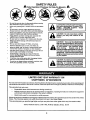
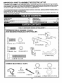
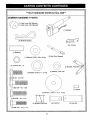
Owner's Manual
JCRRFTSMIIN°J
ELECTRIC LIFT
ACTUATOR KIT
For AUTOMATIC DRIVE
GARDEN TRACTORS
WITH TOP MOUNTED
TRANSAXLE INPUT PULLEY
Model No.
917.242450
CAUTION:
Read and follow all Safety
Rules and Instructions
before operating this
equipment.
•
•
•
•
Safety
Assembly
Operation
Maintenan_
• Repair Part_
Sears, Roebuck and Co., Hoffman Estates, II 60179
Visit our Craftsman
PRINTED IN U.S.A.
website:www.sears.com/craftsman
179284
04,04.01
A
SAFETY RULES
Safe Operation
Practices
IMPORTANT:
THIS CUTTING MACHINE IS CAPABLE
OBJECTS.
FAILURE TO OBSERVE THE FOLLOWING
INJURY OR DEATH.
for Ride-On
Mowers
OF AMPUTATING
HANDS AND FEET AND THROWING
SAFETY INSTRUCTIONS
COULD RESULT IN SERIOUS
I. GENERAL OPERATION
DO NOT:
Read, understand, and follow all instructions in the
manual and on the machine before starting.
Do not turn on slopes unless necessary, and then, turn
slowly and gradually downhill, if possible.
Do not mow near drop-offs, ditches, or embankments.
The mower could suddenly turn over if a wheel is over the
edge of a cliff or ditch, or if an edge caves in.
Do not mow on wet grass. Reduced traction could cause
sliding.
Do not try to stabilize the machine by putting your foot on
the ground.
Only allow responsible adults, who are familiar with the
instructions, to operate the machine.
Clear the area of objects such as rocks, toys, wire, etc.,
which could be picked up and thrown by the blade.
Be sure the area is clear of other people before mowing.
Stop machine if anyone enters the area.
Never carry passengers.
Do not mow in reverse unless absolutely necessary.
Always look down and behind before and while backing.
Be aware of the mower discharge direction and do not
point it at anyone. Do not operate the mower without
either the entire grass catcher or the guard in place.
Slow down before turning.
Never leave a running machine unattended. Always turn
off blades, set parking brake, stop engine, and remove
keys before dismounting.
Turn off blades when not mowing.
Stop engine before removing grass catcher or unclogging
chute.
Do not use grass catcher on steep slopes.
III. CHILDREN
Tragic accidents can occur if the operator is not alert to the
presence of children. Children are often attracted to the machine
and the mowing activity. Neverassume that children will remain
where you last saw them.
Mow only in daylight or good artificial light.
Do not operate the machine while under the influence of
alcohol or drugs.
Watch for traffic when operating near or crossing
roadways.
Use extra care when loading or unloading the machine
into a trailer or truck.
Keep children out of the mowing area and under the
watchful care of another responsible adult.
Be alert and turn machine off if children enter the area.
•
Before and when backing, took behind and down for small
children.
•
Never carry children. They may fall off and be seriously
injured or interfere with safe machine operation.
Never allow children to operate the machine.
Use extra care when approaching blind comers, shrubs,
trees, or other objects that may obscure vision.
•
IV. SERVICE
Use extra care in handling gasoline and other fuels. They
are flammable and vapors are explosive.
Use only an approved container.
Never remove gas cap or add fuel with the engine
running. Allow engine to cool before refueling. Do
not smoke.
Never refuel the machine indoors.
Never store the machine or fuel container inside
where there is an open flame, such as a water heater.
Never run a machine inside a closed area.
Data indicates that operators, age 60 years and above,
are involved in a large percentage of riding mower-related
injunes. These operators should evaluate their ability to
operate the riding mower safely enough to protect
themselves and others from serious injury.
Keep machine free of grass, leaves or other debris buildup which can touch hot exhaust / engine parts and bum.
Do not allow the mower deck to plow leaves
or other debris which can cause build-up to occur. Clean
any oil or fuel spillage before operating or storing the
machine. Allow machine to cool before
storage.
Keep nuts and bolts, especially blade attachment bolts,
tight and keep equipment in good condition.
Never tamper with safety devices. Check their proper
operation regularly.
Keep machine free of grass, leaves, or other debris buildup. Clean oil or fuel spillage. Allow machine to cool
before storing.
Stop and inspect the equipment if you strike an object.
Repair, if necessary, before restarting.
Never make adjustments or repairs with the engine
running.
Grass catcher components are subject to wear, damage,
and deterioration, which could expose moving parts or
allow objects to be thrown. Frequently check components
and replace with manufacturer's recommended parts,
when necessary.
Mower blades are sharp and can cut. Wrap the blade(s)
or wear gloves, and use extra caution when servicing
them.
II. SLOPE OPERATION
Slopes are a major factor related to loss-of-control and tipover
accidents, which can result in severe injury or death. All slopes
require extra caution. If you cannot back up the slope or if you feel
uneasy on if, do not mow it.
DO:
Mow up and down slopes, not across.
Remove obstacles such as rocks, tree limbs, etc.
Watch for holes, ruts, or bumps. Uneven terrain could
overturn the machine. Tal/graascanhideobstac/ee.
Use slow speed. Choose a low gear so that you will not
have to stop or shift while on the slope.
Follow the manufacturer's recommendations for wheel
weights or counterweights to improve stability.
Use extra care with grass catchers or other attachments.
These can change the stability of the machine.
Keep all movement on the slopes slow and gradual. Do
not make sudden changes in speed or direction.
Avoid starting or stopping on a slope. If tires lose traction,
disengage the blades and proceed slowly straight down
the slope.
•
Check brake operation frequently.
required.
2
Adjust and service as
SAFETY RULES
&
Safe Operation
Practices
for Ride-On
Be sure the area is clear of other people before mowing.
Stop machine if anyone enters the area.
Never carry passengers or children even with the blades
off.
&
Look for this symbol to point out important safety precautions. It means CAUTION!!t
BECOME ALERT!H YOUR
SAFETY IS INVOLVED.
Do not mow in reverse unless absolutely necessary.
Always look down and behind before and while backing.
Never carry children. They may fall oft and be seriously
injured or interfere with safe machine operation.
Keep children out of the mowing area and under the
watchful care of another responsible adult.
Be alert and tum machine off if children enter the area.
CAUTION: 0o not coast down a hill in
neutral, you may lose control of the
tractor.
Before and when backing, look behind and down for
small children.
CAUTION: Tow only the attachments
that are recommended by and comply
Mow up and down slopes (15° Max), not across.
Remove obstacles such as rocks, tree limbs, etc.
Q
Mowers
of your tractor. Use common sense
when
towing.
Operate
only at the
with specifications
of the manufacturer
lowest possible speed when on a slope.
Too heavy of a load, while on a slope, is
dangerous. Tires can lose traction with
the ground and ca use you to lose control
of your tractor.
Watch for holes, ruts, or bumps. Uneven terrain could
overturn the machine. Tall grass can hide obstacles.
Use slow speed. Choose a low gear so that you will not
have to stop or shift while on the slope.
Avoid starting or stopping on a slope. If tires lose
traction, disengage the blades and proceed slowly
straight down the slope.
If machine stops while going uphill, disengage blades,
shift into reverse and back down slowly.
Do not turn on slopes unless necessary, and then, turn
slowly and gradually downhill, if possible.
&
CAUTION: In order to prevent accidental
starting when setting up, transporting,
adjusting or making repairs, always
disconnect spark plug wire and place
wire where it cannot contact spark plug.
LIMITED ONE YEAR WARRANTY ON
CRAFTSMAN
ATTACHMENTS
For one year from the date of purchase, when this electric lift attachment is maintained according to the operating and
maintenance instructions in the owner's manual, Sears will repair free of charge any defect in material or workmanship.
This warranty does not cover:
•
Expendable items which become worn during normal use.
•
Repairs necessary because of operator abuse or negligence, including the failure to maintain the equipment
according to instructions contained in the owner's manual.
•
Attachments used for commercial or rental purposes.
Warranty service is available by returning the Craftsman Electric Lift Kit to the nearest Sears Service Center in the United
States. This Warranty applies only while this product is in use in the United States.
This warranty gives you specific legal rights, and you may also have other rights which vary from state to state.
Sears, Roebuck and Co., D/817 Wa, Hoffman Estates, illinois. 60179
3
I
I
BEFORE YOU START TO ASSEMBLE
THE ELECTRIC
LIFT KIT
This electric lift kit is designed for all Vertical shaft Garden Tractors with Gear Drive or Automatic Drive type transaxles.
Th s manua g ves nstructions for tractors with Automatic Drive type transaxle with the input pulley mounted on the top
of the transaxle. If your tractor has a Gear Drive transaxle, or an Automatic Drive type transaxle with the input pulley
mounted on the side of the transaxle, use the other manual supplied in this kit.
AN AUTOMATIC TRANSAXLE HAS INFINITE SPEED CONTROL POSITIONS, AND GEAR DRIVE TRANSAXLE WILL
HAVE RESTRICTED SPEED GEAR SE'n'INGS.
NOTE: Kit assembly will require all COMMON PARTS and only those parts grouped for your particular type tractor. All
remaining parts may be discarded.
OPERATION ...............................................................
12
MAINTENANCE ..........................................................
12
REPAIR PARTS .....................................................
14-15
PARTS ORDERING/SERVICE
..................... Back Page
SAFETY RULES ........................................................
2-3
WARRANTY .................................................................
3
CARTON CONTENTS ...............................................
4-5
ASSEMBLY .............................................................
6-12
***ONLY
HARDWARE
SHOWN
ACTUAL
SIZE***
AUTOMATIC DRIVE ASSEMBLY PARTS
(TOP MOUNTED TRANSAXLE INPUT PULLEY)
(1) Pivot Tube//_"
I1_) J
(2) Pivot P_
(1) Frame Bracket
©
(2) Locknut 5/16-18
Pivot Arm
,!L,L !IJIIIL!III!LI!II!
IILII L
(2) Retainer Spring
COMMON
ELECTRICAL
©
PARTS
(2) Hex Facenut
©
(1) Washer, Lock Int. Tooth
(1) Ground Wire
(1) Wire Tie
(1) Wire Harness
(1) Lift Switch
4
(1) Washer 15/32 x 314 x 16 Ga.
***ONLY HARDWARE SHOWN ACTUAL SIZE***
COMMON
ASSEMBLY
PARTS
(1) Hub, Lever Lift (Splined)
(1) Hub, Lever Lift (Tapered)
(3) Retainer Spring
(2) Lift Link
(1) Bushing
©
(1) Rod, Pivot Support
(1) Washer 13/32 x 7/8 x !6 Ga.
©
(4) Locknut 3/8 - 16
_11111111LIIIII
(1) Washer 21/32 X 1 x 21 Ga.
(1) Bracket, Pivot Rod
(1) Washer, Lock 3/8
(3) Bolt 3/8 - 16 x 7/8
I1111111111LIIIIII
(1) Bolt 318 - 16 x 1-3/8
(1) Spacer
(2) Washer 11/32 x 1-1/2 x 10 Ga.
_IIILILllLIIIILIIILLI
(1) Bolt 3/8 - 16 x 1-1;4
t
i
I
i
°11°
_ •llLIllLItllIHIllltl[llLtltLII
(2) Nyliner, Rod Pivot
(1) Bolt 5/16 - 18 x 1-1/4
5
(2) Pivot Pin
(1) Pivot Pin
(1)
(1)
(2)
(1)
(1)
THESE ARE THE TOOLS YOU
WILL NEED FOR ASSEMBLY:
CAUTION:
BEFORE ASSEMBLING
3/16" Allen Wrench
1/2" Wrench
9/16" Wrenches
9/16" Socket
1/2" Socket
(1)
(1)
(1)
(1)
Drive Ratchet
3" or longer Extension
Phillips Screwdriver
Flat Blade Screwdriver
ACTUATOR KIT TO TRACTOR:
•
Depress clutch/brake pedal fully and set parking brake.
i
Place gearshift/motion
attachment clutchcontrol
in "DISENGAGED"
position,position.
Place
lever in "NEUTRAL"
Turn ignition key "OFF" and remove key.
•
Make sure the blade and all moving parts have completely stopped.
•
Disconnect spark plug wire from spark plug(s) and place wire where it cannot come in contact
with plug,
NOTE: When right hand (R.H.) and left hand (L.H.) are mentioned in this manual, it means when you are seated on the
tractor, in the operator's position.
NOTE: The illustrations shown in this manual are to aid in the assembly and operation of this kit. The illustrations may
not show your particular tractor model.
SET-UP
1.
2.
3.
4.
5.
(See Figs. 1,2 & 3)
6.
Remove socket head screw from lift lever. Remove
lift lever.
NOTE: Use block of wood to assist in lift handle removal.
Remove mower deck if installed (refer to your
"Tractor Owner's Manual" for instructions).
Remove cap, E-Ring, and washer from axle on both
rear wheels.
Place a suitable size block of wood under drawbar
bracket.
Remove rear wheels.
7.
Fit the tapered lift lever hub on lift shaft. Secure with
3/8-16 xl-3/8 hex bolt provided in kit and tighten
securely.
Relieve any tension on attachment lift spring by
loosening jam nut and adjustment bolt.
LIFT
LEVER
JAM
NUT
SOCKETHEAD
SCREW
O
DRAWBAR
O
BRACKET o
Q
5\
ADJU
BOLT
FIG. 2
ATTACHMENT
LIFT SPRING
FIG. 1
TAPERED
LIFT LEVER HUB
HEX BOLT
LIFT SHAFT
6
FIG. 3
PRE-ASSEMBLE
FRAME BRACKET,
TUBE AND ACTUATOR (See Fig. 4)
1.
2.
PIVOT
2.
Position pivot tube on actuator hub, align holes and
insert 2-1/2 in. long pivot pin and secure with retainer
spring•
Position pivot tube in frame bracket, align holes and
insert 2-1/2 in. long pivot pin and secure with retainer
spring.
RETAINER
SPRINGS
3.
4.
On R.H. frame rail install two (2) 5/16-18 x 1 hex
bolts, in direction shown, and Iocknuts. Do not
tighten•
On L.H. frame rail install two (2) 3/8-16 x 1 hex bolts,
in direction shown, and Iocknuts.
Tighten all four bolts and nuts securely.
L.H. FRAME
RAIL
PIVOT TUBE
FRAME BRACKET
AND ACTUATOR
ASSEMBLY
R.H. FRAME
RAIL
PIVOT PINS
2-1/2 IN,
3/8
LOCKNUTS
ACTUATOR
FRAME BRACKET
ASSEMBLY
3/8-16 X 1 ,
HEX BOLTS
FIG. 4
ASSEMBLE
FRAME
ACTUATOR
TO TRACTOR
1.
BRACKET
(See
5/16-18 X 1
HEX BOLTS
AND
Figs.
5-7)
5/16
LOCt_Rn's
Through opening above the rear drawbar, slide
frame bracket and actuator assembly into position
between side rails of frame and align mounting
holes.
FIG. 7
FRAME
BRACKETAND
ACTUATOR
ASSEMBLE
TRACTOR
PIVOT
FRAME
ROD BRACKET
(See Fig. 8)
1.
Install pivot rod bracket to inside of R.H. frame rail
using two hex bolts 3/8-16 x 7/8 and two 3/8-16
Iocknuts.
2.
Tighten hardware securely.
DRAWSAR
FIG. 5
Slide left side
in first
FIG. 8
FIG. 6
7
TO
REMOVE
HEIGHT
INDICATOR
NYLINER
(If equipped)
NYLINER
(See Fig. 9)
1. Remove height indicator (if so equipped) on LH side
of tractor frame. Save all parts except hex bolt for
reassembly.
HEIGHT
INDICATOR
(IF EQUIPPED)
PIVOT ARM
LIFT LINKS
LARGER
PIVOT PIN
FLAT
WASHER
SMALLER
PIVOT PIN
/
""
LOCK
WASHER
SPACER
.ETA,NER/-SPRINGS
HEX BOLT
FLAT
WASHER
SNAP-OUT
COVER
FIG. 9
PRE-ASSEMBLE
(See Fig. 10A)
PIVOT ARM ASSEMBLY
BE SURE SLOT IS
TO LEFT AND
NARROW EDGE IS
TO BO'I-fOM
1.
Assemble both lift links between sides of pivot arm
as shown. Secure with larger pivot pin and retainer
spring•
NOTE: Slots in lift links are not centered and must be
assembled correctly (see figure below). To assemble
hold pivot arm with bent end towards you and downwards. Position lift links so slot is to left and narrow edge
is at bottom (see inset).
2. Place spacer between the two links and insert
smaller pivot pin. Secure with retainer spring.
3. Install two nyliners into pivot bracket as shown.
ATTACH
ACTUATOR
BENT END OF
PIVOT ARM
INSET
FIG. 10A
TO PIVOT ARM
ASSEMBLY (See Fig. 10B)
1.
Position pivot arm assembly under tractor in front of
actuator.
HEX BOLT
3J8-16 X 3-1/4
2.
Insert actuator arm and bushing between pivot arms
as shown. Secure with 3/8-16 x 3-1/4 hex bolt and
Iocknut.
NOTE: Bolt must be assembled in direction shown.
ACTUATOR
BUSHING
LOCKNUT
3/8-16
8
FIG. 10B
INSTALL
TRACTOR
1.
PIVOT
ARM
ASSEMBLY
(See
Figs.
11A & 11B)
A'n'ACH LIFT LINKS TO LIFT SHAFT
BRACKET(See Fig. 12)
TO
1.
Slide 21/32 x 1 x 21 Ga. washer onto pivot rod
support up to nibs.
Position one lift link on each side of the lift shaft
bracket as shown. Insert smaller pivot pin and
secure with retainer spring.
NISS
LIFT
SHAFT
BRACKET
PIVOT ROD
LIFT LINK
(One on each side of
lift shaft bracket)
SUPPORT
21/32 X 1 X 21 GA.
WASHER
RETAINER
SPRING
\
SMALLER
PIVOT PIN
FIG. 11A
2.
3.
4.
Insert pivot rod support with washer through nyliners
in pivot arm, as shown. Raise entire assembly until
nyliners are in line with hole in LH side of tractor
frame. Loosely assembly hex bolt 3/8-16 x 7/8 and
lock washer through hole in LH side of frame. Do
not tighten at this time.
Assemble flattened end of pivot rod support to
underside of pivot rod bracket using hex bolt 3/8-16
x 1-1/4, flat washer and Iocknut and tighten securely.
Now tighten previously assembled 3/8-16 x 718 hex
bolt on LH side of frame.
3/8-16 X 7/8
HEX BOLT
LOCK
WASHER
NYLINERS AND
PIVOT ARM
3/8-16 X 1-1/4
HEX BOLT
FLAT
WASHER
FIG. 12
ACTUATOR
HOLEIN LH _DE
OFTRACTOR
FRAME
LOCKNUT
PIVOT ROD
SUPPORT
PIVOT ROD
BRACKET
FIG. 11B
9
WIRING
I
_
ASSEMBLY
(See Figs. 13 thru 18)
PLASTIC DASH WITHOUT HOLE AND PLUG
system, disconnect battery. Reconnect
CAUTION:Beforeworking
onelectrical
battery when finished.
1.
Locate the black plastic hole plug in upper right or left
corner of dash. Remove plug from dash and discard.
NOTE: Some dashes do not have a hole and plug for the
lift switch. These are plastic dashes that can be identified
by a magnet mounted on top of the dash which holds the
hood in place. Using the template provided on page 11
of this manual, drill a 1/2" dia. hole in the dash for
mounting the lift switch (See Fig. 13B).
2.
3.
4.
DRILL 1/2 IN. DIA. HOLE
USING TEMPLATE
PROVIDED ON PAGE 13
Install one face nut on lift switch and tighten
securely.
Insert lift switch into dash hole (with Keyway down)
from underside of dash. Install flat washer, intemal
tooth Iockwasher and remaining face nut onto lift
switch and tighten nut securely.
Connect ground wire (black single wire) to lift switch.
a. Viewing lift switch from under hood, connect
black wire to upper left hand side terminal of
switch.
FIG, 13B
LIFT
b. Connect opposite end (eyelet) under the right or
left upper rear battery support nut. The support
nut is located on the inside of the side panel.
SW,TCN
SLACK
Cw , ODNO
ILJ,I '..-',r'u
HOLE PLUG
FIG. 14
UPPER REAR SUPPORT
BOLT AND NUT - USE
EITHER RIGHT OR LEFT
SiDE FOR GROUNDING
SIDE
PANEL
FIG. 13A
FIG. 15
10
WIRE TIE
5.
6.
Connect lift harness to electric actuator.
a. Connect male connector of harness to female
connector of electric actuator.
ACTUATOR
WIRING
HARNESS
LIFT
HARNESS
PIVOT ROD
Viewing lift switch from under hood connect lift
harness to lift switch.
a. Connect yellow wire of lift harness to lower right
terminal of lift switch.
b. Connect double red wire of lift harness to lower
left terminal of lift switch.
7.
8.
9.
c. Connect single red wire to upper right terminal.
Secure wiring harness.
a. Loosely attach wire tie around pivot rod support
and wiring harness.
b. Ensure wire routing does not allow wires to rest
on sharp edges or near moving parts.
c. Tighten wire tie.
Raise hood, insert female connector of lift harness
into male connector of tractor harness.
FIG. 17
Ensure wire routing does not allow wires to rest on
sharp edges or near moving parts.
(TOP)
FEMALE CONNECTOR
LIFT
:i_il_.
BLACK
(GROUND)
WIRE
i _;_
VIEWED
BEHIND
FROM
DASH
(LIFT HARNESS)
_j
MALE CONNECTOR
_
(TRACTOR
I
_'_
(CUT AWAY)
0
LOWER
TERMINALS
HARNESS)
_DASH
0
VIEW FROM
LEFT SIDE OF
TRACTOR
SINGLE
RED WIRE
FIG. 18
DRILL TEMPLATE
PLACE OVER HEIGHT OF CUT
SYMBOL ON DASH AND DRILL
1/2" DIA. HOLE.
YELLOW
DOUBLE
RED Wl
FIG. 16
11
REASSEMBLE
HEIGHT
equipped) (See Fig. 19)
INDICATOR
OPERATION
(If
1.
Reassemble previously removed height indicator
adding two spacer washers and replacing old hex
bolt with the 5/16-18 x 1-1/4 hex bolt provided with
this kit.
2.
Ensure height indicator is showing correct position of
deck. This may be adjusted after final assembly of
deck by loosening the hex bolt and moving height
indicator to correct position in relation to deck, then
retighten hex bolt and replace snap-out cover.
Assemble all parts in order shown.
AND MAINTENANCE
Make sure all bolts and nuts are tight and retainer
springs are secure.
carefully before operating your Electric
CAUTION:
Read the Safety Rules
Actuator.
HEIGHT
INDICATOR
1.
Ignition switch must be "ON" to operate electric lift
actuator.
2.
After you install lift switch follow markings already on
dashboard.
3.
If you hear a ratcheting sound, you know you are
fully raised or fully lowered. Release switch promptly
after ratcheting begins.
iA CAO O.I
FLAT
WASHER
ground when turning corners, reversing
or transporting.
\
LOCK
WASHER
NEW HEX
NOTE: The electric actuator is equipped with an overload circuit that will trip when overloaded. Unit will
automatically reset after 10 seconds.
ADO SPACER
LUBRICATION
1.
FLAT
WASHER
FIG. 19
REASSEMBLE
•
I
2.
TRACTOR
•
Reinstall rear wheel and mower deck, if removed
earlier.
Remove wood block.
•
•
Reconnect spark plug wire(s).
Retighten lift assist spring bolt.
12
The Electric Actuator is lubricated for normal life. If
Actuator is disassembled for repair, upon
reassembly lubricate with high performance extreme
pressure lubricating grease.
Apply a light coat of grease to threaded areas and
pivot points.
ELECTRIC
ACTUATOR
ACTUATOR
BREAKDOWN
KIT- - MODEL NUMBER
917.242450
8
10
12
KEY
NO.
PART
NO.
1862J
2
3
4
5
6
7
1863J
8331J
1857J
1865J
1864J
677A149
DESCRIPTION
KEY
NO.
Screw - SI. Fil, Hd. Mach. No. 10-32
x 1-5/8
Lockwasher - No. 10
Housing Cover
Cover Gasket
Snap Ring
Retaining Ring
Spring Washer (Use 3 or 4 as
req'd.)
13
PART
NO.
8
9
10
11
12
674A281
1859J
1861J
673A218
13
14
1860J
1858J
DESCRIPTION
Pawl & RampWasher
Out put Gear
Motor- 12V
Connector Body Kit
Not Serviced Separately Order
complete actuator Part# 124371X
Thrust Washer
Intermediate Gear
ELECTRIC
ACTUATOR
KIT- - MODEL
NUMBER
917.242450
AUTOMATIC DRIVE
(WITH TOP MOUNTED TRANSAXLE INPUT PULLEY)
PARTS BREAKDOWN
11
_46
47
2
2O
31
14
\
35
20,
43
32
27
5
30
28
14
ELECTRIC
ACTUATOR
KIT- - MODEL
NUMBER
917.242450
AUTOMATIC DRIVE
(WITH TOP MOUNTED TRANSAXLE INPUT PULLEY)
PARTS BREAKDOWN
KEY
NO.
2
5
10
11
12
13
14
15
16
17
18
19
20
21
22
23
24
25
26
27
28
29
30
31
32
35
38
43
44
46
47
48
49
PART
NO.
74780652
74760622
10040600
74760620
5950J
74780614
4939M
139276
179199
19211621
138914
138948
73800600
19131416
138912
138905
138947
138909
127017X
8984R
7320R
7319R
19151216
124371X
156816
179210
9698R
179201
179197
74760520
19112410
74780514
73800500
DESCRIPTION
Bolt, Hex 3/8-16 x 3-1/4 Grade 5
Bolt, Hex 3/8-16 x 1-3/8
Washer, Lock
Bolt, Hex 3/8-16 x 1-1/4
Bushing .384 x 1/2 x 1-1/4
Bolt, Hex 3/8-16 x 7/8
Spdng, Retainer
NylineF
Arm, Pivot
Washer 21/32 x 1 x 21 Ga.
Rod, Pivot Support
Pin, Pivot 5/8 x 1-1/2
Locknut 3/8-16
Washer 13/32 x 7/8 x 16 Ga.
Bracket, Pivot Rod
Link, Lift
Pin, Pivot 1/2 x 3/4
Spacer
Harness, Lift Kit
Switch, Lift
Nut, Switch
Washer, Lock Int. Tooth
Washer 15/32 x 3/4 x 16 Ga.
Electric, Actuator
Hub, Lever Lift (Tapered)
Pin, Pivot 2-1/2"
Wire, Ground
Bracket, Frame
Tube, Pivot
Bolt, Hex 5/16-18 x 1-1/4
Washer 11/32 x 1-1/2 x 10 Ga.
Bolt, Hex 5/16-18 x 7/8
Locknut 5/16-18
15
For repair of major brand appliances in your own home...
no matter who made it, no matter who sold itt
1-800-4-MY-HOME _
(1_00-469_e3)
AnyOne,
dayornight
(U,S._andCanada)
Www.sear_corn
For repair of cany-in products like vacuums, lawn equipment, and
electronics, call for the nearest Sears Parts and Repair Center.
1-800-488-1222
Any_me,
dayorrKj_(U.SJ_orgy)
www.seal_com
For the replacement parts, accessories and owner's manuals
thatyou need to do-it-yourseff,call Sears PartsDirectS"!
1-800-366-PART
6&m.-11
(14Y30_66-7278)
p.m., 7daysaweek
(U.S_
only)
_comtm_d_
To purchase or inquireabouta Sears ServiceAgreement
or Sears MaintenanceAgreement:
1-800-827-6655
(u.s_)
7 a.m. - 5 p.m., CST, Mort. - Sat
1-800-361-6665
(Canada)
9 a.m.- 8 p.m. EST, M- F, 4 p.rn. Sat.
Au C_,anadapour senlice en frar_ais:
1-800-LE-FrO_R Me
© Sear_ RoebuckandCo.
® Registered Trademark / TM Trademark / s_ Service Mark of Sears, Roebuck and Co.
® Mama Registrada / TMMarca de Fdbdca / SMMarca de Servicio de Sears, Roebuck and Co,
uc Marque de commerce / MoMarque ddposee de Sears, Roebuck and Co.
16