1
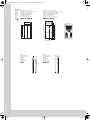
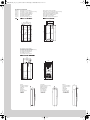
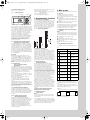
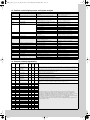
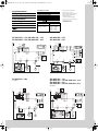
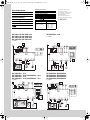
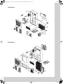
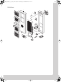
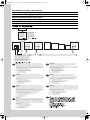
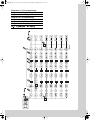
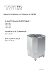
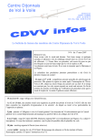
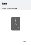
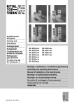
00_Umschl_Ti_SK3302.fm Seite 1 Donnerstag, 8. Dezember 2005 12:04 12
RITTAL
TOP
THERM
SchaltschrankKühlgerät
Cooling unit
Climatiseur
Koelaggregaat
Kylaggregat
Condizionatore
per armadi
Refrigerador
para armarios
SK 3302.xxx SK 3304.xxx
SK 3328.xxx SK 3332.xxx
SK 3303.xxx SK 3305.xxx
SK 3329.xxx
Montageanleitung
Assembly instructions
Notice de montage
Montage-instructie
Montageanvisning
Istruzioni di montaggio
Instrucciones de montaje
R
01_SK3302_xxx_2-7_05.fm Seite 2 Donnerstag, 8. Dezember 2005 12:12 12
SK 3302.xxx
Abb. 3.1 Montageausschnitt Anbau
Fig. 3.1
Mounting cut-out for external mounting
Fig. 3.1
Coupe de montage rapporté
Afb. 3.1
Montage-uitsparing aanbouw
Bild 3.1
Montageavsnitt påbyggnad
Fig. 3.1
Montaggio sporgente
Fig. 3.1
Recorte de montaje exterior
Montageausschnitt Teileinbau
Mounting cut-out for partial internal mounting
Coupe de montage rapporté partiel
Montage-uitsparing gedeelt. inbouw
Montageavsnitt delinbyggnad
Montaggio semincassato
Recorte de montaje interior parcial
280
254
251
200
280
25
280
550
550
518
266
492
524
550
501
Ø 15 (2x)
Ø 8 (4x)
18 x 45°
(230)
Anbau
External installation
Installation externe
Aanbouw
Utanpå
Sporgente
Montaje exterior
2
140
Einbau
Internal installation
Installation interne
Inbouw
Inbyggnad
Incassato
Montaje interior
98
42
01_SK3302_xxx_2-7_05.fm Seite 3 Donnerstag, 8. Dezember 2005 12:12 12
SK 3303.xxx
Abb. 3.1 Montageausschnitt Anbau
Mounting cut-out for external mounting
Fig. 3.1
Coupe de montage rapporté
Fig. 3.1
Montage-uitsparing aanbouw
Afb. 3.1
Montageavsnitt påbyggnad
Bild 3.1
Montaggio sporgente
Fig. 3.1
Recorte de montaje exterior
Fig. 3.1
280
262
254
15.5
280
25
Montageausschnitt Teileinbau
Mounting cut-out for partial internal mounting
Coupe de montage rapporté partiel
Montage-uitsparing gedeelt. inbouw
Montageavsnitt delinbyggnad
Montaggio semincassato
Recorte de montaje interior parcial
Ø 8 (4x)
550
492
266
518
524
532
480
550
266
Ø 8 (4x)
18 x 45°
(230)
Montageausschnitt Einbau
Mounting cut-out for internal mounting
Coupe de montage installation
Montage-uitsparing inbouw
Montageavsnitt inbyggnad
Montaggio incassato
Recorte de montaje interior
280
254
280
25
200
550
550
518
266
492
524
Ø 19 (2x)
Ø 8 (4x)
18 x 45°
(230)
Anbau
External installation
Installation externe
Aanbouw
Utanpå
Sporgente
Montaje exterior
Teileinbau
Partial internal mounting
Rapporté partiel
Gedeelt. inbouw
Delinbyggnad
Semincassato
Interior parcial
Einbau
Internal installation
Installation interne
Inbouw
Inbyggnad
Incassato
Montaje interior
42
200
100
100
158
3
01_SK3302_xxx_2-7_05.fm Seite 4 Donnerstag, 8. Dezember 2005 12:12 12
SK 3304.xxx / SK 3305.xxx
Abb. 3.1 Montageausschnitt Anbau
Fig. 3.1
Mounting cut-out for external mounting
Fig. 3.1
Coupe de montage rapporté
Afb. 3.1
Montage-uitsparing aanbouw
Bild 3.1
Montageavsnitt påbyggnad
Fig. 3.1
Montaggio sporgente
Fig. 3.1
Recorte de montaje exterior
Montageausschnitt Teileinbau
Mounting cut-out for partial internal mounting
Coupe de montage rapporté partiel
Montage-uitsparing gedeelt. inbouw
Montageavsnitt delinbyggnad
Montaggio semincassato
Recorte de montaje interior parcial
36.5
330
345
280
370
250
235
400
400
920
920
255
950
380
350
385
950
Ø 9.5 (8x)
25 x 45°
350
25
15
Ø 9.5 (4x)
Montageausschnitt Einbau
Mounting cut-out for internal mounting
Coupe de montage installation
Montage-uitsparing inbouw
Montageavsnitt inbyggnad
Montaggio incassato
Recorte de montaje interior
400
370
R6 (4x)
25
950
25 x 45°
380
920
950
920
2
400
Ø 9.5 (4x)
Anbau
External installation
Installation externe
Aanbouw
Utanpå
Sporgente
Montaje exterior
4
260
Teileinbau
Partial internal mounting
Rapporté partiel
Gedeelt. inbouw
Delinbyggnad
Semincassato
Interior parcial
105
155
Einbau
Internal installation
Installation interne
Inbouw
Inbyggnad
Incassato
Montaje interior
210
50
01_SK3302_xxx_2-7_05.fm Seite 5 Donnerstag, 8. Dezember 2005 12:12 12
SK 3328.xxx / SK 3329.xxx
Abb. 3.1 Montageausschnitt Anbau
Fig. 3.1
Mounting cut-out for external mounting
Fig. 3.1
Coupe de montage rapporté
Afb. 3.1
Montage-uitsparing aanbouw
Bild 3.1
Montageavsnitt påbyggnad
Fig. 3.1
Montaggio sporgente
Fig. 3.1
Recorte de montaje exterior
Montageausschnitt Einbau, Teileinbau
Mounting cut-out for internal mounting, partial internal mounting
Coupe de montage installation, rapporté partiel
Montage-uitsparing inbouw, gedeelt. inbouw
Montageavsnitt inbyggnad, delinbyggnad
Montaggio incassato, semincassato
Recorte de montaje interior, interior parcial
370
280
320
400
320
1580
1580
1540
1558
376
325
260
Ø 13 (10x)
1554
1580
550
350
380
R95 (2x)
295
35
400
400
275
340
Ø 13 (4x)
25
R95 (2x)
Anbau
External installation
Installation externe
Aanbouw
Utanpå
Sporgente
Montaje exterior
320
290
Teileinbau
Partial internal mounting
Rapporté partiel
Gedeelt. inbouw
Delinbyggnad
Semincassato
Interior parcial
145
145
Einbau
Internal installation
Installation interne
Inbouw
Inbyggnad
Incassato
Montaje interior
240
50
5
01_SK3302_xxx_2-7_05.fm Seite 6 Donnerstag, 8. Dezember 2005 12:12 12
362
500
25
500
380
380
500
440
Anbau
External
installation
Installation externe
Aanbouw
Utanpå
Sporgente
Montaje exterior
Montageausschnitt Teileinbau
Mounting cut-out for partial
internal mounting
Coupe de montage rapporté partiel
Montage-uitsparing gedeelt. inbouw
Montageavsnitt delinbyggnad
Montaggio semincassato
Recorte de montaje interior parcial
1580
1580
474
Ø 13 (4x)
25
275
375
440
360
164
Ø 13 (10x)
1530
1550
1580
500
330
45
SK 3332.xxx
Abb. 3.1 Montageausschnitt Anbau
Fig. 3.1 Mounting cut-out for
external mounting
Fig. 3.1 Coupe de montage rapporté
Afb. 3.1 Montage-uitsparing aanbouw
Bild 3.1 Montageavsnitt påbyggnad
Fig. 3.1 Montaggio sporgente
Fig. 3.1 Recorte de montaje exterior
Abb. 3.2
Fig. 3.2
Fig. 3.2
Afb. 3.2
Bild 3.2
Fig. 3.2
Fig. 3.2
Gerätemontage
Mounting
Montage de l’appareil
Apparaatmontage
Aggregatmontage
Montaggio dell’apparecchio
Montaje del aparato
Anbau
External installation
En saillie
Aanbouw
Utanpå
Montaggio sporgente
Montaje exterior
Teileinbau
Partially internal installation
Partiellement intégré
Gedeeltelijke inbouw
Delvis inbyggnad
Montaggio semincassato
Montaje parcial
3302. . . .
Einbau
Internal installation
Intégré
Inbouw
Inbyggnad
Montaggio incassato
Montaje interior
6
340
Teileinbau
Partial internal
mounting
Rapporté partiel
Gedeelt. inbouw
Delinbyggnad
Semincassato
Interior parcial
145
195
01_SK3302_xxx_2-7_05.fm Seite 7 Donnerstag, 8. Dezember 2005 12:12 12
Tab. 2.1
Tab. 2.1
Tab. 2.1
Tab. 2.1
Tab. 2.1
Tab. 2.1
Tab. 2.1
D
GB
F
NL
Technische Daten
Technical data
Données techniques
Technische gegevens
Tekniska data
Caratteristiche tecniche
Datos técnicos
Farbton Edelstahlhaube
RAL
1.4301
7035
Bemessungsspannung
Bemessungsstrom
Anlaufstrom
VorEinschaltsicherung dauer
T
Bemessungsleistung
Nutzkühlleistung
Kältemittel
Colour
RAL
7035
Operating
voltage
Rated
current
Starting
current
Pre-fuse
T
Nom.
refrigeration
Useful cooling
output
Coloris Capot en acier
RAL
inoxydable
7035
1.4301
Tension
nominale
Courant
nominal
Courant de
démarrage
Dispositif Durée de
de
mise en
sécurité T circuit
Puissance
nominale
Kleur
RAL
7035
Bedrijfsspanning
Nominale
stroom
Aanloopstroom
Primaire
zekering
T
Inschakelduur
Inkopplingstid
Stainless
steel cover
1.4301
RVS mantel
1.4301
Duty cycle
zul.
Druck
PS
Temperaturbereich
Geräuschpegel
Schutzart
Innenkreislauf
Außenkreislauf
Abmessungen
(B x H x T)
mm
Gewicht
Refrigerant Permissible
pressure
Temperature
range
Noise
level
Protection categ.
Internal circuit
External circuit
Dimensions
(W x H x D)
mm
Weight
Puissance
frigorifique
de régime
Fluide
frigorigène
Pression
de régime
autor.
Plage de
température
Niveau
sonore
Degré de protect.
Circuit intérieur
Circuit extérieur
Dimensions
(L x H x P)
mm
Poids
Nominaal
vermogen
Nuttig
koelvermogen
Koelmiddel
p. max.
Temperatuurbereik
Geluidsnivo Beschermklasse
Inwendig circuit
Uitwend. circuit
Afmetingen
(B x H x D)
mm
Gewicht
Märkeffekt
Effektiv
kyleffekt
Kylmedel
Tillåtet
driftsövertryck
Temperaturområde
Ljudnivå
Kapslingsklass
Inre kretslopp
Yttre kretslopp
Mått
(B x H x D)
mm
Vikt
Färgton Huv i rostfritt
RAL
stål 1.4301
7035
Anslutningsspänning
Märkström
Startström
S
Försäkring
gL
Colore
RAL
7035
Cover in acciaio
inox 1.4301
Tensione
nominale
Corrente
nominale
Corrente
di spunto
Fusibili T Ciclo
Potenza
d’inserzione nominale
Potenza
frigorifera utile
Fluido
Pressione
frigorigeno max.
Campo di
temperatura
Livello
di rumore
Grado di protez.
Circuito interno
Circuito esterno
Dimensioni
(L x A x P)
mm
Peso
I
Color
RAL
7035
Cubierta de acero
inoxidable
1.4301
Tensión
de
servicio
Intensidad
nominal
Intensidad
de
arranque
Fusible T Duración
de
conexión
Potencia
nominal
Potencia
frigorífica útil
Fluido
frigorífico
Campo de
temperaturas
Nivel
de ruido
Protección
Circuito interior
Circuito exterior
Dimensiones
(anch. x alt.
x prof.) mm
Peso
E
J
RAL
7035
1.4301
L35 L35
L35 L50
DIN 3168/EN 814
L35 L35
L35 L50
SK 3302.110
SK 3302.100
SK 3302.210
SK 3302.200
SK 3303.100
SK 3303.500
SK 3303.110
SK 3303.510
SK 3304.100
SK 3304.500
SK 3304.110
SK 3304.510
SK 3304.140
SK 3304.540
SK 3305.100
SK 3305.500
SK 3305.110
SK 3305.510
SK 3305.140
SK 3305.540
SK 3328.100
SK 3328.500
SK 3328.110
SK 3328.510
SK 3328.140
SK 3328.540
SK 3329.100
SK 3329.500
SK 3329.110
SK 3329.510
SK 3329.140
SK 3329.540
SK 3332.140
SK 3332.540
SK 3304.101
SK 3304.501
SK 3304.111
SK 3304.511
SK 3304.141
SK 3304.541
SK 3305.101
SK 3305.501
SK 3305.111
SK 3305.511
SK 3305.141
SK 3305.541
SK 3328.101
SK 3328.501
SK 3328.111
SK 3328.511
SK 3328.141
SK 3328.541
SK 3329.101
SK 3329.501
SK 3329.111
SK 3329.511
SK 3329.141
SK 3329.541
SK 3332.141
SK 3332.541
SK 3303.200
SK 3303.600
SK 3303.210
SK 3303.610
SK 3304.200
SK 3304.600
SK 3304.210
SK 3304.610
SK 3304.240
SK 3304.640
SK 3305.200
SK 3305.600
SK 3305.210
SK 3305.610
SK 3305.240
SK 3305.640
SK 3328.200
SK 3328.600
SK 3328.210
SK 3328.610
SK 3328.240
SK 3328.640
SK 3329.200
SK 3329.600
SK 3329.210
SK 3329.610
SK 3329.240
SK 3329.640
SK 3332.240
SK 3332.640
SK 3304.201
SK 3304.601
SK 3304.211
SK 3304.611
SK 3304.241
SK 3304.641
SK 3305.201
SK 3305.601
SK 3305.211
SK 3305.611
SK 3305.241
SK 3305.641
SK 3328.201
SK 3328.601
SK 3328.211
SK 3328.611
SK 3328.241
SK 3328.641
SK 3329.201
SK 3329.601
SK 3329.211
SK 3329.611
SK 3329.241
SK 3329.641
SK 3332.241
SK 3332.641
115 V, 60 Hz,
230 V, 50/60 Hz
3.3 A
1.6 A/
1.7 A
8.0 A
3.0 A/
3.4 A
10.0 A/
10.0 A
230 V, 50/60 Hz
2.6 A/
2.6 A
5.1 A/
6.4 A
10.0 A/
10.0 A
115 V, 60 Hz
5.7 A
11.5 A
10.0 A
4.8 A/
4.4 A
9.5 A/
10.0 A
2.5 A/
2.6 A
5.4 A/
6.0 A
11.0 A/
12.5 A
2.3 A/
2.6 A
6.9 A/
8.5 A
13.6 A/
16.2 A
2.5 A/
3.0 A
8.0 A/
10.0 A
16.0 A/
21.0 A
3.4 A/
3.5 A
3.8 A/
3.9 A
5.4 A/
5.0 A
10.6 A/
11.1 A
2.8 A/
2.9 A
6.0 A/
6.5 A
12.1 A/
13.6 A
2.6 A/
2.9 A
7.5 A/
9.1 A
14.7 A/
17.3 A
2.8 A/
3.3 A
8.6 A/
10.6 A
17.0 A/
21.0 A
3.8 A/
3.8 A
4.4 A/
4.4 A
12.0 A/
14.0 A
26.0 A/
28.0 A
11.5 A/
12.7 A
22.0 A/
24.0 A
42.0 A/
46.0 A
12.2 A/
11.3 A
22.0 A/
26.0 A
36.0 A/
39.0 A
6.5 A/
7.5 A
21.0 A/
21.0 A
44.0 A/
42.0 A
6.5 A/
7.3 A
9.2 A/
11.0 A
12.0 A/
14.0 A
26.0 A/
28.0 A
11.5 A/
12.7 A
22.0 A/
24.0 A
42.0 A/
46.0 A
12.2 A/
11.3 A
22.0 A/
26.0 A
36.0 A/
39.0 A
6.8 A/
7.8 A
21.0 A/
21.0 A
44.0 A/
42.0 A
6.8 A/
7.6 A
9.8 A/
11.5 A
10.0 A/
10.0 A
16.0 A/
16.0 A
10.0 A*/
10.0 A*
16.0 A/
16.0 A
20.0 A/
20.0 A
10.0 A*/
10.0 A*
16.0 A/
16.0 A
25.0 A/
25.0 A
10.0 A*/
10.0 A*
16.0 A/
16.0 A
25.0 A/
25.0 A
10.0 A*/
10.0 A*
10.0 A*/
10.0 A*
10.0 A/
10.0 A
16.0 A/
16.0 A
10.0 A*/
10.0 A*
16.0 A/
16.0 A
20.0 A/
20.0 A
10.0 A*/
10.0 A*
16.0 A/
16.0 A
25.0 A/
25.0 A
10.0 A*/
10.0 A*
16.0 A/
16.0 A
25.0 A/
25.0 A
10.0 A*/
10.0 A*
10.0 A*/
10.0 A*
230 V, 50/60 Hz
115 V, 50/60 Hz
400, 3~, 50/60 Hz,
460 V, 3~, 60 Hz
230 V, 50/60 Hz
115 V, 50/60 Hz
400, 3~, 50/60 Hz,
460, 3~, 60 Hz
230 V, 50/60 Hz
115 V, 50/60 Hz
400, 3~, 50/60 Hz,
460, 3~, 60 Hz
230 V, 50/60 Hz
115 V, 60 Hz
400, 3~, 50/60 Hz,
460, 3~, 60 Hz
400, 3~, 50/60 Hz,
460, 3~, 60 Hz
230 V, 50/60 Hz
115 V, 50/60 Hz
400, 3~, 50/60 Hz,
460, 3~, 60 Hz
230 V, 50/60 Hz
115 V, 50/60 Hz
400, 3~, 50/60 Hz,
460, 3~, 60 Hz
230 V, 50/60 Hz
115 V, 50/60 Hz
400, 3~, 50/60 Hz,
460, 3~, 60 Hz
230 V, 50/60 Hz
115 V, 60 Hz
400, 3~, 50/60 Hz,
460, 3~, 60 Hz
400, 3~, 50/60 Hz,
460, 3~, 60 Hz
290 W/ 340 W
100%
100%
100%
100%
100%
100%
100%
100%
100%
100%
100%
100%
245 W/ 255 W
255 W/ 275 W
360 W/ 380 W
420 W/ 390 W
470 W
500 W
700 W/ 650 W
750 W/ 710 W
725 W/ 680 W
780 W/ 750 W
580 W/ 550 W
660 W/ 680 W
850 W/1000 W
1000 W/1160 W
880 W/1050 W
1040 W/1200 W
800 W/ 980 W
960 W/1150 W
900 W/1070 W
1130 W/1220 W
960 W/1130 W
1170 W/1290 W
930 W/1150 W
1150 W/1400 W
1320 W/1550 W
1500 W/1880 W
1380 W/1600 W
1550 W/1940 W
1300 W/1500 W
1550 W/1850 W
1710 W/2110 W
1980 W/2450 W
825 W/ 775 W
875 W/ 835 W
850 W/ 800 W
900 W/ 875 W
700 W/ 675 W
785 W/ 800 W
975 W/1125 W
1125 W/1285 W
1000 W/1175 W
1165 W/1325 W
925 W/1100 W
1085 W/1275 W
1025 W/1200 W
1250 W/1350 W
1085 W/1250 W
1300 W/1410 W
1050 W/1275 W
1275 W/1525 W
1450 W/1675 W
1625 W/2000 W
1500 W/1725 W
1675 W/2065 W
1425 W/1625 W
1675 W/1975 W
1950 W/2350 W
2220 W/2700 W
Presión
máxima
admis.
EN 60 529
300 W/ 320 W
150 W/ 170 W
R134a,
100 g
R134a,
100 g
25 bar
+20 –
+55°C
< 61dB (A) IP 54/IP 34
280 x 550 x 140
13 kg
500 W/ 610 W
280 W/ 350 W
R134a,
170 g
28 bar
+20 –
+55°C
< 61dB (A) IP 54/IP 34
280 x 550 x 200
17 kg
25 bar
+20 –
+55°C
1000 W/1060 W
790 W/ 840 W
R134a,
325 g
39 kg
< 64 dB (A) IP 54/IP 34
400 x 950 x 260
R134a,
500 g
44 kg
40 kg
41 kg
1500 W/1510 W
1230 W/1250 W
R134a,
600 g
25 bar
+20 –
+55°C
< 64 dB (A) IP 54/IP 34
400 x 950 x 260
46 kg
42 kg
66 kg
2000 W/2350 W
1450 W/1690 W
R134a,
950 g
28 bar
+20 –
+55°C
< 64 dB (A) IP 54/IP 34
400 x 1580 x 290 73 kg
67 kg
2500 W/2750 W
1600 W/1750 W
69 kg
R134a,
950 g
2500 W/2700 W
1900 W/1950 W
4000 W/4400 W
3070 W/3570 W
R134a,
3000 g
1000 W/1060 W
790 W/ 840 W
R134a,
500 g
28 bar
+20 –
+55°C
28 bar
+20 –
+55°C
25 bar
+20 –
+55°C
< 64 dB (A) IP 54/IP 34
400 x 1580 x 290 76 kg
70 kg
< 65 dB (A) IP 54/IP 34
500 x 1580 x 340 91 kg
39 kg
< 64 dB (A) IP 54/IP 34
400 x 950 x 260
44 kg
40 kg
41 kg
1500 W/1510 W
1230 W/1250 W
R134a,
600 g
25 bar
+20 –
+55°C
< 64 dB (A) IP 54/IP 34
400 x 950 x 260
46 kg
42 kg
66 kg
2000 W/2350 W
1450 W/1690 W
R134a,
950 g
28 bar
+20 –
+55°C
< 64 dB (A) IP 54/IP 34
400 x 1580 x 290 73 kg
67 kg
2500 W/2750 W
1600 W/1750 W
2500 W/2700 W
1900 W/1950 W
4000 W/4400 W
3070 W/3570 W
69 kg
R134a,
950 g
R134a,
3000 g
28 bar
+20 –
+55°C
< 64 dB (A) IP 54/IP 34
400 x 1580 x 290 76 kg
28 bar
+20 –
+55°C
< 65 dB (A) IP 54/IP 34
500 x 1580 x 340 91 kg
70 kg
Technische Änderungen vorbehalten. Technical modifications reserved. Sous réserve de modifications techniques. Technische wijzigingen voorbehouden.
Tekniska ändringar förbehålles. Rittal si riserva di appor tare eventuali modifiche tecniche. Se reserva el derecho a realizar cambios técnicos.
* Motorschutzschalter, motor circuit breaker, disjoncteur-protecteur, motorbeveiligingsschakelaar, motorskyddsbrytare, salvamotore, guardamotor.
7
03_S_3302_xxx_12_15_eng.fm Seite 10 Donnerstag, 8. Dezember 2005 12:15 12
English
Contents
1. Application
2. Technical data
3. Wall mounting
4. Safety notices
5. Electrical connection
6. Commencing operation and control
behaviour
7. Supplementary functions
8. BUS system
9. Technical information
10. Handling Instructions
11. Scope of supply and guarantee
12. Display screen and system analysis
13. Comfort control programming
1. Application
Enclosure cooling units are designed and built
to dissipate heat from enclosures by cooling
the air inside the enclosure and protecting
temperature-sensitive components. Enclosure
cooling units are particularly suitable for a
temperature range of +40°C to +55°C.
the mains connection ratings, as stated
on the rating plate, are available;
the ambient temperature does not exceed
+55°C;
the packaging shows no signs of damage.
Traces of oil on damaged packaging are an
indication of refrigerant loss and of leakage in
the unit system. Any damage to the packaging
may be the cause of subsequent malfunctions;
the enclosure is sealed on all sides (IP 54).
Condensation will occur if the enclosure is leaky;
the separation of the units from one another
and from the wall should not be less than
200 mm;
air inlet and outlet are not obstructed on the
inside of the enclosure;
units are only fitted horizontally in the specified
position.
Max. deviation from the true horizontal: 2°;
condensate drainage is provided (see 9.3);
electrical connection and repair are carried out
only by authorised personnel.
Use only original replacement parts and
accessories.
to avoid an increase in condensation, a dooroperated switch (e.g. PS 4127.000) should be
used which will switch the cooling unit off when
the enclosure door is opened (see 7.3);
losses from the components installed in
the enclosure must not exceed the specific
refrigeration capacity of the cooling unit itself;
the customer must not modify the cooling unit
in any way.
2. Technical data
(see table 2.1)
3. Wall mounting
According to production model, the wallmounted unit can be mounted, installed, or
partially installed, to choice (up to SK 3302.xxx
and SK 3332.xxx). Cut out the sections and drill
according to Fig. 3.1 at the fitting level.
3.1 Mounting
Cut the enclosed seals to the required length and
attach to the unit in accordance with Fig. 3.2.
Screw tapped pins into the blind nuts on the rear
of the unit. The unit is then to be secured using
washers and nuts.
3.2 Installation
First of all, the lamellar grid and belt are to be
removed. The plug is to be removed from the
display screen on the inner side of the belt.
Cut the enclosed seals to the required length
and attach to the unit in accordance with Fig. 3.2.
Loosen the nuts and washers, then fasten the unit
to the enclosure with the washers and nuts.
3.3 Partial installation
For partial installation the unit cover is to be
separated from the chassis. First of all, remove
the lamellar grid and belt. Carefully disconnect
the plug from the display screen. Loosen the
4 nuts and washers of the cover. Pull the cover
a little bit to the front. Disconnect the safety
connection between cover and chassis and
separate the plug-in connection for the fan.
Remove the unit cover completely. Loosen the
4 spacer bolts from the chassis. Attach the
enclosed seal all-round along the edge of the
chassis (see Fig. 3.2). Slide the chassis into
the mounting cut-out and screw-fasten with
4 spacer bolts. It is now fitted to the enclosure
in reverse sequence.
4. Safety notices
The following safety notices are to be observed
in their entirety for the correct use of the
equipment:
To prevent the enclosure with the cooling unit
fitted tipping over, it is essential that this be
bolted to the floor.
A roller door is to be used to ensure problemfree opening and closing of the enclosure
door.
A transportable enclosure with built-in cooling
unit may only be produced if an additional
transport anchorage to support the cooling
unit is used.
Prior to mounting, ensure that:
the site for the enclosure, and hence the
arrangement of the cooling unit, is selected
so as to ensure good ventilation;
the location is free from excessive dirt and
moisture;
the cutout for air extraction is located
in the upper area of the enclosure;
12
6. Commencing operation
and control behaviour
Following the completion of mounting and a
waiting period of approximately 30 minutes
(to allow oil to collect in the compressor in order
to ensure lubrication and cooling).
6.1 Basic control system
Version .....100 / .110 / .140
The cooling unit operates automatically, i.e. after
electrical connection, the evaporator fan will run
continuously to circulate the air inside the
enclosure. The installed basic controller (setting
the desired internal temperature; factory setting
+35°C) provides automatic control switch-off of
the cooling unit by the set value of the fixed
switching difference of 5 K.
6.1.1 Temperature setting at the basic
controller
First of all, the lamellar grid and belt with the
incorporated display is to be removed from the
unit. The display lock is then to be slackened and
this is to be pushed forward off the lamellar grid/
belt. Finally, the display screen (1) is carefully
removed, e.g. with a screwdriver. The desired
nominal temperature can be set on the
potentiometer (2) which is now accessible. After
the temperature has been set, the display of all
screens in the lamellar grid is to be locked once
more. The lamellar grid and belt are to be
fastened to the unit again.
Fig. 6.1 Basic controller
5. Electrical connection
The connected voltage and frequency must correspond to the values stated on the rating plate.
During commissioning, the data on the rating
plate of the device shall apply. The cooling unit
must be connected to the mains via an all-pin isolating device which ensures at least 3 mm contact
opening when switched off. The unit must not
have any additional temperature control connected up-stream at the supply end. The fans and
compressors built into single and three-phase
devices are intrinsically safe (thermal winding
protection).
This also applies to SK 3304.110 / .510,
SK 3305.110 / .510, SK 3328.110 / .510,
SK 3329.110 / .510 transformer types, and to
specially rated units which are also fitted with a
transformer.
Line protection should be provided by means of
the pre-fuse specified on the rating plate. Only
one automatic cutout should be connected between the cooling unit and the power supply. A
time-lag backup-fuse as specified on the rating
plate (safety cutout K-characteristic or time-lag
lead fuse) is mandatory.
The three phase supplies for the SK 3304. . . . /
SK 3305. . . . / SK 3328. . . . / SK 3329. . . . /
SK 3332. . . . must be connected via a motor safety
switch to a TN grid with grounded star point.
Summation current as specified on the rating
plate. Specially rated three-phase units must be
protected by means of transformer safety
switches (category AC-6A) specified on the rating
plate.
For units designed for three phase 400/460 V,
the rotary field or the absence of a phase is also
monitored. If the rotary field is incorrect or a phase
is absent, the unit will not run.
The cooling unit does not have its own surge
protection. Surge protection must be provided
by the operator in the power supply wiring,
including both lightning and power surge
protection. The power supply voltage must
not deviate from the tolerances by any more
than +/–10 %.
In accordance with IEC 61 000-3-11, the unit is
intended solely for use at sites with a continuous
current-carrying capacity (incoming mains power
supply) > 100 A per phase and with a supply
voltage of 400/230 V. If necessary, the power
supply company must be consulted to ensure that
the continuous current-carrying capacity at the
point of connection to the public grid is sufficient
for connection of the unit. The chosen mains
connection form must guarantee low-noise
equipotential bonding.
Observe the relevant regulations during
installation!
1
3
4
2
5
6.1.2 Operation of the basic controller
The basic controller monitors and controls the
cooling unit. After the supply voltage has been
connected, the green LED (3) lights to indicate
readiness for operation. The green LED is
connected in series with a door limit switch, and
flashes if the enclosure door is opened. The red
LED (4) signals too high a temperature inside the
enclosure; at 5 K above the set value, the red LED
comes on permanently. In addition, the excess
temperature message can still be queried via an
integrated potential-free contact in the cooling
unit connection terminal.
K1 fault signal relay with changeover contact
Terminal 3: NC (normally closed)
Terminal 4: C (connection between voltage
supply and fault signal relay)
Terminal 5: NO (normally open)
The definitions NC and NO refer to the deenergised state. As soon as voltage is applied to
the cooling unit, the fault signal relay picks up.
As a result, the relay contacts change their state
(contact 3 – 4 open; contact 4 – 5 closed),
representing the normal operating status of the
cooling unit. As soon as a system message
occurs or the voltage supply is interrupted, the
relay drops out. (see also circuit diagrams on
page 39).
The high pressure alarm in the cooling circuit is
indicated by the red LED flashing. In this case,
the unit is to be reset manually, by pressing the
rubberized potentiometer display (5) for
3 seconds (see 6.1.1).
If the red LED flashes on the SK 3302.xxx, check
the plug connector on the board and replace if
necessary.
Test mode
By holding down the potentiometer for 5 seconds,
the cooling unit will commence cooling operation,
irrespective of the setpoint.
03_S_3302_xxx_12_15_eng.fm Seite 11 Donnerstag, 8. Dezember 2005 12:15 12
6.2 Comfort controller control
Version .....500 / .510 / .540
Fig. 6.2 Comfort controller
H2 = Button
°C
H4 = Button
/set
K1/K2 fault signal relay (normally open contact):
Terminal 3: Fault signal relay 2
Terminal 4: Voltage supply connection for both
fault signal relays
Terminal 5: Fault signal relay 1
(see circuit diagrams on page 39).
7. Supplementary functions
H1 = Display terminal
H3 = Button
°F
After electrical connection the internal fan turns on
and circulates the enclosure air. This helps assure
even temperature distribution within the enclosure.
The condenser fan and compressor are controlled
by the Comfort controller. The minimum break time
is 3 min. The switching difference is 5 K, but
can be set in the range 2 – 10 K. To avoid short
switching cycles and hence the danger of
inadequate or only partial cooling in some
sections of the enclosure, the switching difference
should be set to be only as low as necessary.
For economic reasons (energy saving), the
nominal value of the internal enclosure
temperature Ti should also be set to be only
as low as necessary.
6.2.1 Operation of the Comfort controller
(see diagram 13.1 Programming)
The display terminal H1 consists of a 3 position
7-segment display which indicates the internal
enclosure temperature in °C or °F (changeable)
as well as any fault codes. The actual enclosure
internal temperature is constantly displayed on
H1. When a system message is generated, this
alternates in the display with the current internal
enclosure temperature. While programming the
unit, the programming level and prescribed value
are also displayed.
Test mode
By simultaneously holding down keys H2
(°C key) and H4 ( /set key) for 5 seconds, the
cooling unit will commence cooling operation,
irrespective of the setpoint. The door limit switch
function is disregarded in such cases. After
approximately 5 minutes or upon reaching 15°C,
the device deactivates cooling operation once
again.
6.2.2 Programming
(see 13.1 Comfort controller
programming)
In the EEPROM of the Comfort controller various
parameters are stored which can be changed by
using the buttons H2, H3 and H4. 24 changeable
parameters can be set via 24 programme levels in
the stated ranges (max. and min. values).
To this end, input code “22” is required (see
diagram 13.1).
The H2, H3 and H4 keys are multiple occupancy.
To access programming mode, set 5 sec is to be
pressed and held down.
Primary occupancy (only diode displays):
H2: °C, H3: °F, H4: Alarm
Secondary occupancy (for programming):
H2: Arrow upwards, H3: Arrow downwards,
H4: set
Programming via diagnostic software (order no.
SK 3159.100) is also an option. The programming
cable interface is the connecting cable plug,
located on the rear of the Comfort controller. To do
this, the lamellar grid and the belt also are to be
removed if necessary.
6.2.3 System messaging equipment
All system messages at the cooling unit are
recorded and displayed as an error number
by H1. System messages alternate in the display
with the current internal enclosure temperature.
(see 12. Comfort control fault display and error
analysis).
6.2.3.1 System message contacts
(K1 and K2; potential free)
Both relays are normally closed. All system
messages assigned to an individual relay result
in it opening. If the control voltage fails, this also
results in the relay opening and can hence be
captured and documented in the log file.
According to individual weighting, all system
messages can be assigned to both relays or
suppressed. Terminal strip X3 provides the
connection. See the wiring diagram for contact
data and occupancy.
7.1 Filter mat use and changing
The PU foam filter mat available as an accessory
is coarse and filters large dust particles or fluff
from the air. Metallic filter mats are used to trap
oil condensate. These are also available as an
accessory. Subject to the suction of the blower
being high enough, fine dust is blown through
the filter mat and the external circuit of the unit.
This does not affect the unit's operation.
Fig. 7.1 Filter mat replacement
8. BUS system
(Model No.: Master-slave cable SK 3124.100)
8.1 General
The BUS system allows a maximum of
10 cooling units to be interconnected.
As a result, the following functions are available
to the operator:
Parallel unit control (the cooling units in the
network can be simultaneously switched on
and off)
Parallel door status messages (“door open”)
Parallel collective fault message
The data exchange is carried out using masterslave cables (shielded, two-wire leads). All units
are assigned an address. This address also
includes the ID for “master” or “slave”.
8.2 Installation notices for the X2 interface
(Jack X2)
Note!
The electrical signals at the interface are of an
extra-low voltage (not extra-low safety voltages
to EN 60 335). Always heed the following notes!
De-energise the cooling units to be
connected.
Ensure proper electrical insulation.
Make sure the cables are not laid in parallel
to power lines.
Make sure that the lines are short.
8.3 Programming the cooling unit
See diagram 13.1 for details on programming.
ID’s:
7.2 Filter mat monitoring
Function of the filter mat monitor:
The filter mat is monitored for soiling by measuring the temperature difference in the external circulation of the cooling unit (see Diagram 13.1:
Programming on page 49). In the event of any
filter mat soiling, the temperature difference will
increase. The nominal value of the temperature
difference in the external circuit is matched to the
relevant operating points in the characteristic
fields. Hence there is no requirement to adjust the
nominal value for different unit operating points.
7.3 Door limit switch S1
(supplied by customer)
Where a door limit switch is used and the
enclosure door is open (contact is closed when
door is open), the cooling unit (fans and
condenser) will switch off after approx. 15 s.
This only applies to devices with a comfort
controller and devices with a three-phase
connection to the basic controller. For devices
with a basic controller (115 V, 230 V and 400 V,
2~), the internal fan is not switched off when using
a door limit switch. Thereby avoiding an increase
in condensation while the door is open. To avoid
cyclic operation, switch-on of condenser and
external fan is delayed by about 3 minutes after
the cooling unit has been switched off.
The internal fan will start up after about 15 s on
closure of the door. Connection is made at the
terminals 1 and 2. The extra low voltage is
supplied by the internal power pack, current is
approx. 30 mA DC. Each door limit switch must
only be assigned to one cooling unit. Several door
limit switches may be operated on one cooling
unit (parallel connection). The minimum crosssection of the connection cable is 0.3 mm2 for a
cable length of 2 m. The resistance of the door
limit switch contact must not exceed a maximum
of 50 Ω.
Connect the door limit switch free from
potential only, no external voltage!
7.4 Interface X3 (option)
(Connector X3)
Note!
The electrical signals at the interface are of an
extra-low voltage (not extra-low safety voltages
to EN 60 335).
Master cooling unit
Slave cooling unit
00
Basic state
00
Basic state
01
Master
with 1 slave
11
Slave
with address 1
02
Master
with 2 slaves
12
Slave
with address 2
03
Master
with 3 slaves
13
Slave
with address 3
04
Master
with 4 slaves
14
Slave
with address 4
05
Master
with 5 slaves
15
Slave
with address 5
06
Master
with 6 slaves
16
Slave
with address 6
07
Master
with 7 slaves
17
Slave
with address 7
08
Master
with 8 slaves
18
Slave
with address 8
09
Master
with 9 slaves
19
Slave
with address 9
Note
Only one unit may be configured as master;
the address ID must match the number of slave
units.
The individual slave units must have different
addresses; the addresses must be in ascending
order (without gaps in between).
Example:
1 master cooling unit with 2 slave cooling units
Master
02
Slave
11
Slave
12
(see wiring example of master/slave and door
limit function, page 46/47).
The 9-pin SUB-D connector X3 can be used to
connect additional interface cards for integrating
cooling units with higher level monitoring systems.
These cards are also available as an accessory.
(Model No.: Interface card SK 3124.200).
13
03_S_3302_xxx_12_15_eng.fm Seite 12 Donnerstag, 8. Dezember 2005 12:15 12
Fig. 9.3 Condensate discharge
English
1 cooling unit, ready for connection
1 drilling template
1 sealing tape
1 set of mounting and operating instructions
1 plug-in terminal strip
9. Technical information
The cooling unit (compressor refrigeration unit)
consists of four main components: the coolant
compressor, evaporator, condenser, and the
control or expansion valve, which are connected
by suitable pipework. This circuit is filled with a
readily boiling substance, the refrigerant. The
R134a (CH2FCF3) refrigerant is free from
chlorine. It has an ozone destroying potential
(ODP) of 0 and is therefore environmentally
friendly. A filter dryer which is integrated in the
hermetically sealed cooling circuit, provides
effective protection against moisture, acid, dirt
particles, and foreign bodies within the cooling
circuit.
Guarantee:
This unit is covered by a 1-year guarantee from the
date of supply, subject to correct usage (see also
Safety notices under heading 4.). Within this period,
the returned unit will be repaired in the factory or
replaced free of charge. The cooling unit is to be
used for the cooling of enclosures only. If it is
connected or handled improperly the
manufacturer’s guarantee does not apply and in
this case we are not liable for any damage caused.
9.1 Operation of the cooling unit
Fig. 9.1 Operation of the cooling unit
Liquefier
PSAH
monitor
Compressor
Fan 2
External circuit
Internal circuit
Filter
dryer
Thermostat
Evaporator
Expansion valve
Fan 1
The compressor takes the gaseous refrigerant
from the evaporator and compresses it to a higher
pressure in the condenser. During this process
the temperature of the refrigerant rises above the
ambient temperature and heat can be dissipated
to the environment via the surface of the
condenser. Then the refrigerant is liquefied and,
by means of a thermostatically controlled
expansion valve, returned to the evaporator, where
it evaporates at low pressure. The heat required
for complete evaporation is drawn from the
enclosure interior causing it to cool down.
The cooling cycle is thus completed, the
aforementioned process of the heat transfer starts
afresh.
9.2 Safety equipment
The cooling circuit of the cooling unit has a
component-tested, high-pressure monitor to
EN 12 263, which is set to maximum PS (allowed
pressure) and operates via an automatic reset
device in case of recurring pressure drop.
Temperature monitoring will prevent the
evaporator from icing up. If there is a risk of icing
up, the compressor
is switched off and automatically switched on
again at higher temperatures. The refrigerant
compressor and the fans are equipped with
thermal winding protection switches against
excess current and excess temperatures.
9.3 Condensate discharge
A drain pipe fitted to the evaporator divider
panel ensures that any condensate which may
form on the evaporator (at high air humidity,
low temperatures inside the enclosure) is
drained away from the bottom of the unit.
For this purpose, a length of hose should be
fitted to the condensate pipe connection piece
(see fig. 9.3, if appropriate, remove the grille).
The condensate must be able to run off freely.
If the condensate is to be drained off over a
greater distance, then care must be taken that
the hose is free from kinks and a check for
correct drainage made.
14
11. Scope of supply and
guarantee
9.4 Electronic evaporation
The SK 33xx.xx1 cooling units possess an
automatic electronic condensate evaporation
feature. Any condensate formed (see 9.3) is
collected in the external circuit of the cooling unit.
In the case of excessive condensate formation,
the evaporation function is activated via a
separate heating cartridge. The direct evaporation principle provides for effective evaporation.
The relevant safety notes (see Point 4.) must be
observed!
10. Handling Instructions
Storage, maintenance, transport and disposal
As a maintenance-free, hermetically sealed
system, the cooling circuit has been filled in the
factory with the required amount of refrigerant,
and tested for leaks and subjected to a function
trial run.
The installed maintenance-free fans use ball
bearings, they are protected against moisture
and dust, and are fitted with a temperature
monitor. The life expectancy is at least 30,000
operating hours. The cooling unit is thus largely
maintenance free. All that may be required from
time to time is that the components of the external
air circuit are cleaned by compressed air.
The use of a filter mat is recommended only if
large particles of lint are present in the air, so
that blockage of the condenser is prevented.
(Filter mat replacement, fig. 7.1). Note: Prior to
any maintenance work, the power to the cooling
unit must be disconnected.
Storage temperature: The cooling units must not
be exposed to temperatures above +70°C.
Transport position: The cooling units must always
be transported upright.
Waste disposal: The closed cooling circuit
contains refrigerant and oil which must be
correctly disposed of for the protection of the
environment. Disposal can be carried out at
Rittal.
We reserve the right to make technical
modifications.
03_S_3302_xxx_12_15_eng.fm Seite 13 Donnerstag, 8. Dezember 2005 12:15 12
12. Comfort control display screen and system analysis
Alarm no.
A01
System message
Open the enclosure door
A02
A04
Internal temperature of enclosure too
high
Filter monitoring
Ambient temperature too high/too low
A05
Icing hazard
A06
PSAH monitor
A07
A08
Evaporator
Condensate warning
A09
A10
A11
Condenser fan
Condenser fan
Compressor
A03
A12
A13
A14
A15
A16
A17
A18
A19
A20
Condenser temperature sensor
Ambient temperature sensor
Icing temperature sensor
Condensate warning temperature
Internal temperature sensor
Phase monitoring
Cause
Door open or door limit switch not correctly
positioned
Cooling capacity too low/unit undersize
Sequence errors in messages A03 to A17
Filter mat soiled
Ambient temperature outside the permissible
operating range (+10°C to +60°C)
Icing hazard display according to operating
mode
Ambient temperature too high
Condenser soiled
Filter mat soiled
Condenser fan defective
E-valve defective
PSAH monitor fault
Refrigerant fault
Only in units with optional condensate
evaporation
Blocked or defective
Blocked or defective
Compressor overloaded
(internal winding protection)
Defective (check by measuring the
winding resistance)
Open or short circuit
Open or short circuit
Open or short circuit
Open or short circuit
Open or short circuit
Incorrect rotary field/phase absent
Remedy
Close door, position door limit switch correctly,
check connection if necessary
Check cooling capacity
Clean or exchange
Raise or lower the ambient temperature
(e.g. heat or ventilate the room)
Increase the nominal value of
the internal enclosure temperature
Unit operating limits exceeded
Clean
Clean or exchange
Exchange
Repair by refrigeration engineer
Refrigeration engineer to exchange
Repair by refrigeration engineer
Check condensate drainage; repair kinks or
blockages in the hose as necessary
Clear the blockage; exchange if necessary
Clear the blockage; exchange if necessary
Unit switches in again independently
Refrigeration engineer to exchange
Exchange
Exchange
Exchange
Exchange
Exchange
Exchange two phases
EPROM error
LAN/Master-Slave
Voltage drop
Master and slave not linked
Setting or check cable
Fault display is not illustrated
Event is saved in the log file
Connection problem (display and control board) Reset by means of power supply (OFF/ON)
E0
Display signal
Cable faulty; plug connection loose
Replacement of the boards
The fault displays A03, A06 and A07 are to be reset manually. To do this, hold down the ▲ and ▼ keys simultaneously for 5 seconds.
13. Comfort control programming
Level
Display
screen
changeable
parameter
min. max. Factory
value value setting
Explanation
1
St
Nominal value of
the internal
enclosure
20
55
The nominal value of the internal enclosure temperature is set at the factory to 35°C and is
variable over a 20°C range to 55°C.
2
Fi
Filter mat
monitoring
10
99
60
(99 = off)
3
Ad
0
19
0
4
CF
0
1
0
5
H1
Master-slave
programming
Temperature
conversion
Temperature
switching
2
10
5
6
H2
Difference for error
message 2
3
15
5
7
8
9
10
11
12
13
14
15
16
17
18
19
20
21
22
23
24
25
A1
A2
A3
A4
A5
A6
A7
A8
A9
A10
A11
A12
Relay connection
Relay connection
Relay connection
Relay connection
Relay connection
Relay connection
Relay connection
Relay connection
Relay connection
Relay connection
Relay connection
Relay connection
Relay connection
Relay connection
Relay connection
Relay connection
Relay connection
Relay connection
Relay connection
0
0
0
0
0
0
0
0
0
0
0
0
0
0
0
0
0
0
0
2
2
2
2
2
2
2
2
2
2
2
2
2
2
2
2
2
2
2
0
0
0
0
0
1
2
1
1
1
2
1
1
1
1
1
1
0
0
A13
A14
A15
A16
A17
A18
A19
35
For activation of filter mat monitoring, the display is to be set to a minimum of 10 K above
the temperature difference shown in programming mode “Fi”; filter mat monitoring is
switched off at the factory. (Display 99 = off).
see 8.3 “Cooling unit programming”
The temperature display can be switched from °C (0) to °F (1). The corresponding LED
displays the current unit of temperature.
The cooling unit is set in the factory for a switching cycle of 5 K. This parameter should only
be changed after agreement with the manufacturer.
If the internal enclosure temperature exceeds the set value by more than 5 K, then error
message 2 (internal enclosure temperature too high) appears on the display terminal. The
difference of 5 K can be changed if required over the rang 3 K to 15 K.
The fault messages (1 to 19) depicted in the display can also be evaluated using two
potential-free fault message relays. Comfort control provides the option to group fault
messages accordingly and assign them to both fault message relays. The value “1” is to be
programmed for assignment and evaluation of the relevant fault message via relay 1.
If the fault is to be evaluated via relay 2, then the value “2” is to be programmed accordingly.
If the value is set to “0”, the system message appears only in the display.
This accordingly enables the user to define the system weighting himself, by apportioning
between relays 1 and 2.
15
10_SK3302_xxx_40_51_05.fm Seite 38 Donnerstag, 8. Dezember 2005 12:27 12
D
A1
A2
A3
B1
B2
B3
B4
B5
C1-C4
F2
F3
K1
K2
L1
L2
M1
M2
M4
R1
S1
T1
X1
X2
X3
H1
NL
A1
A2
A3
B1
B2
B3
B4
B5
C1-C4
F2
F3
K1
K2
L1
L2
M1
M2
M4
R1
S1
T1
X1
X2
X3
H1
E
Anschlußschema
Comfortcontroller
= Leistungsplatine
= Anzeigeterminal
= Anlassrelais und R–C Glied
= Temperaturfühler Innentemperatur
= Temperaturfühler Vereisungsschutz
= Temperaturfühler außen 1
= Temperaturfühler außen 2
= Kondensatwarnsensor
= Betriebskondensatoren
= PSAH-Wächter, (bei 3302.1x0
kein Pressostat sondern Brücke)
= Thermokontakt Verdichter
= Relais Sammelstörung 1
= Relais Sammelstörung 2
= LED Betrieb grün
= LED Alarm rot
= Verdichter
= Verflüssigerventilator
= Verdampferventilator
= Potentiometer
zur Setpoint-Einstellung
= Türendschalter (ohne Türendschalter
Klemme 1, 2 offen)
= Trafo
= Hauptanschlußklemmleiste
= Master/Slave-Anschluß
= Optionale Schnittstelle
= Kondensatverdunster
GB Wiring diagram
comfort controller
A1
A2
A3
B1
B2
B3
B4
B5
C1-C4
F2
F3
K1
K2
L1
L2
M1
M2
M4
R1
S1
T1
X1
X2
X3
H1
Aansluitschema
comfortcontroller
= Hoofdstroomprint
= Display
= Startrelais en R–C-element
= Temperatuursensor interne temp.
= Temperatuursensor ijsvorming
= Temperatuursensor buiten 1
= Temperatuursensor buiten 2
= Condens waarschuwingssensor
= Motorcondensator
= PSAH-pressostaat, (bij 3302.1x0
geen pressostaat maar brug)
= Thermisch relais compressor
= Relais verzamelstoring 1
= Relais verzamelstoring 2
= LED bedrijf, groen
= LED alarm rood
= Compressor
= Condensorventilator
= Verdamperventilator
= Potmeter
voor instellen gewenste waarde
= Deurschakelaar (zonder deurschakelaar klem 1, 2 open)
= Transformator
= Hoofdaansluitklemmenstrook
= Master/slave-aansluiting
= Optionele interface
= Condensaatverdamper
S
Anslutningsschema
comfortcontroller
A1
A2
A3
B1
B2
B3
B4
B5
C1-C4
F2
= Drivkort
= Display terminal
= Startrelä och R–C länk
= Temperaturgivare innertemperatur
= Temperaturgivare nedisningsrisk
= Temperaturgivare yttre 1
= Temperaturgivare yttre 2
= Kondensvarningssensor
= Startkondensator
= PSAH-vakt, (vid 3302.1x0
ingen pressostat utan bygling)
= Termokontakt kompressor
= Samlingsrelä felsignaler 1
= Samlingsrelä felsignaler 2
= LED drift grön
= LED alarm röd
= Kompressor
= Kondensorfläkt
= Förångarfläkt
= Potentiometer
för setpoint-inställning
= Dörrströmbrytare (utan dörrströmbrytarklämma 1, 2 öppna)
= Trafo
= Huvudkontaktplint
= Master/Slave-anslutning
= Optional anslutning
= Kondensavdunstare
F3
K1
K2
L1
L2
M1
M2
M4
R1
S1
T1
X1
X2
X3
H1
Esquema de conexiones
del controlador Confort
= Pletina de potencia
= Pantalla indicadora
= Relé de arranque y fusible R–C
= Sonda térmica de la temp. en el
interior del armario
B2
= Sonda térmica protección
contra congelación
B3
= Sonda térmica exterior 1
B4
= Sonda térmica exterior 2
B5
= Sensor de condensación
C1-C4 = Condensador electrolitico de servicio
F2
= Presostato PSAH, (en 3302.1x0
sin presostato sino puente)
F3
= Contacto térmico compresor
K1
= Relé de fallo 1
K2
= Relé de fallo 2
L1
= LED servicio verde
L2
= LED alarma rojo
M1
= Compresor
M2
= Ventilador del condensador
M4
= Ventilador del evaporador
R1
= Potenciómetro
para ajuste de valores
S1
= Interruptor de puerta (sin interruptor
final borne 1, 2 abierto)
T1
= Transformador
X1
= Regleta de bornes principal
X2
= Conexión maestro/esclavo
X3
= Interfaz opcional
H1
= Evaporador de condensado
= Power PCB
= Display terminal
= Start-up relay and R–C component
= Internal temperature sensor
= Icing hazard temperature sensor
= Temperature sensor, external 1
= Temperature sensor, external 2
= Condensate warning sensor
= Operating capacitors
= PSAH monitor,
(in the 3302.1x0 no pressure-sensitive
switch but a bridge)
= Compressor thermal contact
= Relay collective fault 1
= Relay collective fault 2
= Green operating LED
= Red alarm LED
= Compressor
= Condenser fan
= Evaporator fan
= Setpoint adjustment potentiometer
= Door limit switch
(without door operated
switch terminal 1, 2 open)
= Transformer
= Main terminal strip
= Master/slave connection
= Optional interface
= Condensate evaporator
J
A1
A2
A3
B1
40
H1
=
F
A1
A2
A3
B1
B2
B3
B4
B5
C1-C4
F2
F3
K1
K2
L1
L2
M1
M2
M4
R1
S1
T1
X1
X2
X3
H1
I
A1
A2
A3
B1
B2
Schéma électrique
régulateur confort
= Platine de puissance
= Display terminal
= Relais de démarrage temporisé
= Sonde de température intérieure
= Sonde de veille anti-givre
= Sonde de température extérieure 1
= Sonde de température extérieure 2
= Avertisseur de condensats
= Condensateurs de régime
= Témoin pression PSAH, (sauf 3302.1x0 :
le pressostat est remplacé par un pont)
= Contact bilame du compresseur
= Relais défauts 1
= Relais défauts 2
= LED fonction – vert
= LED alerte – rouge
= Compresseur
= Ventilateur du condenseur
= Ventilateur de l’évaporateur
= Potentiomètre
pour l’étalonnage
= Interrupteur de porte (en absence
d’interrupteur bornes 1, 2 ouvertes)
= Transformateur
= Bornier principal
= Port maître/esclave
= Interface (option)
= Evaporateur de condensats
Schema allacciamenti
controllore Comfort
= Scheda di potenza
= Display terminale
= Relais di avviamento
= Sonda temperatura interna
= Sonda temperatura,
pericolo di formazione di ghiaccio
B3
= Sonda temperature esterna 1
B4
= Sonda temperature esterna 2
B5
= Sensore allarme condensa
C1-C4 = Condensatore d’esercizio
F2
= Controllo PSAH, (eccetto 3302.1x0
F3
= Contatto termico compressore
K1
= Relè segnalatore guasti 1
K2
= Relè segnalatore guasti 2
L1
= LED esercizio verde
L2
= LED allarme rosso
M1
= Compressore
M2
= Ventilatore del condensatore
M4
= Ventilatore dell’evaporatore
R1
= Potenziometro per setpoint
S1
= Interruttore della portina (senza interruttore i morsetti 1, 2 sono aperti)
T1
= Trasformatore
X1
= Morsettiera a raccordo princiale
X2
= Raccordo Master/Slave
X3
= Interfaccia opzione
H1
= Evaporatore di condensa
10_SK3302_xxx_40_51_05.fm Seite 39 Donnerstag, 8. Dezember 2005 12:27 12
Technische Daten siehe Typenschild
Kontaktdaten K1/K2/KX
Contact Data K1/K2/KX
Caracteristiques des contacts K1/K2/KX
Kontaktgegevens K1/K2/KX
Kontaktdata K1/K2/KX
Caratteristiche dei contatti K1/K2/KX
Características del contacto K1/K2/KX
K1/K2/KX
Anschlußschema
Wiring diagram
Schéma électrique
Aansluitschema
Anslutningsschema
Schema allacciamenti
Esquema de conexiones
AC
cosf = 1
I max. = 2 A
U max. = 250 V
Données techniques voir plaque signalétique
Technische gegevens zie typenplaatje
Tekniska data se typskylt
Caratteristiche tecniche vedi targhetta
Datos técnicos véase placa de características
DC
L/R = 20 ms
I min. = 100 mA
U max. = 200 V
I max. = 2 A
U max. = 18 V
I max. = 2 A
SK 3303.500 / .510,
SK 3303.600 / .610
21
SK 3302.100 / .110, SK 3303.100 / .110,
SK 3302.200 / .210, SK 3303.200 / .210
Technical data see name plate
21
5
Netz
Netz
A2
22
S1
L2
X1 L1 N
PE 1
123
L N
Power
L1
2
1
3
2
PE 1
2
3
5
4
2
X3
X2
3
1
2
NTC I
S1
B2
MS1
Serial NTC I
NTC E
2
NTC C
2
M4
1 2 3
F2
M1
1 2 3
B3
B4
2
B5
4
Term
A1
B2
2
NTC A
P
B1
2
Level
2
F2 1
M2
1 2 3
1 2 3 2 1
S1 K2
K1
Kx
A2
8
PE
8
Term
A1
12 3
L N
Power
B1
2
NTC E
Kx
M1
1 2 3
L2
N
X1 L1
5
4
3
R1
L2
PE
5
S1
22
PE
2
M4 F2 1
1 2 3
M2
1 2 3
P F2
C4
S
C4
PE
C1
C1
R
S
C2
C
F3
M
1~
M
1~
M2
M4
R
C2
C
M1
F3
M
1~
M
1~
M2
M4
M1
SK 3305.10x / .11x,
SK 3328.10x / .11x, SK 3329.10x / .11x,
SK 3305.20x / .21x,
SK 3328.20x / .21x, SK 3329.20x / .21x
SK 3304.10x / .20x
x = 0 bzw. 1
21
21
x = 0 bzw. 1
Netz
S1
22
S1
22
Netz
PE
PE
5
5
X1 L1 L2 N
PE 1
2
3
5
4
L1
X1 L1 L2
N
R1
L2
A2
L1 L2
L1
H1
T1
1
2
3
2
1
NTC I
S1
NTC E
Kx
Term
A1
2
F2 1
M2
1 2 3
M1
1 2 3
C1
5
4
L1
R1
L2
H1
2
2
B1
123
L N
Power
PE
B2
S
3
C
M2
A
1
NTC I
NTC E
Kx
Term
2
F2 1
M2
1 2 3
R
C12
C11
M
1~
M4
2
M1
1 2 3
M4
1 2 3
R
C2
3
P F2
C4
M
1~
2
S1
A1
P
1
1
8
C
M1
3
L N
123
L N
Power
F3
2
A2
T1
L N
PE
PE 1
L2
M1
2
B1
B2
8
P F2
M4
1 2 3
C4
A3
4
1
2
5
C2
F3
2
M
1~
M
1~
M2
M4
41
10_SK3302_xxx_40_51_05.fm Seite 40 Donnerstag, 8. Dezember 2005 12:27 12
Technische Daten siehe Typenschild
Kontaktdaten K1/K2/KX
Contact Data K1/K2/KX
Caracteristiques des contacts K1/K2/KX
Kontaktgegevens K1/K2/KX
Kontaktdata K1/K2/KX
Caratteristiche dei contatti K1/K2/KX
Características del contacto K1/K2/KX
K1/K2/KX
Anschlußschema
Wiring diagram
Schéma électrique
Aansluitschema
Anslutningsschema
Schema allacciamenti
Esquema de conexiones
AC
cosf = 1
I max. = 2 A
U max. = 250 V
SK 3304.14x, SK 3305.14x,
SK 3328.14x, SK 3329.14x,
SK 3304.24x, SK 3305.24x,
SK 3328.24x, SK 3329.24x
Technical data see name plate
Données techniques voir plaque signalétique
Technische gegevens zie typenplaatje
Tekniska data se typskylt
Caratteristiche tecniche vedi targhetta
Datos técnicos véase placa de características
DC
L/R = 20 ms
I min. = 100 mA
U max. = 200 V
I max. = 2 A
U max. = 18 V
I max. = 2 A
SK 3304.50x / .60x
x = 0 bzw. 1
21
21
x = 0 bzw. 1
Netz
S1
22
S1
Netz
PE
22
PE
5
X2
5
X1 L1 L2 L3 PE 1
2
3
4
X1 L1 L2
N
5
L1
T1
2
3
X3
A2
5
4
6
3
R1
L2
A2
H1
PE 1
T1
H1
3 2 1
R S T
Power
PE
1 2
S1
2
4
1
3
NTC I
NTC E
Term
Kx
2
2
B1
123
L N
Power
PE
B2
8
1 2
S1
2
1
MS1 Serial
F3 F2
1 2 3 4
M2
F4
1 2 3 4 1 2 3
M4
1 2 3
K1
K2
2
2
NTC C
Kx
F5
1 2
2
NTC I
NTC E
2
NTC A
A1
A1
M1
1 2 3 4
3
M1
1 2 3
M4
1 2 3
M2
1 2 3
Level
2
Term
2
F2
1
4
B1
B2
B3
B4
B5
P
F2
P
C1
C4
F2
U
V
F3
W
M
M
3~
M2
3~
M4
1
R
S
C2
F3
M1
3
C
M1
M
1~
M
1~
M2
M4
SK 3304.54x, SK 3305.54x,
SK 3328.54x, SK 3329.54x,
SK 3304.64x, SK 3305.64x,
SK 3328.64x, SK 3329.64x
x = 0 bzw. 1
x = 0 bzw. 1
21
SK 3305.50x / .51x,
SK 3328.50x / .51x, SK 3329.50x / .51x,
SK 3305.60x / .61x,
SK 3328.60x / .61x, SK 3329.60x / .61x
PE
5
Netz
X2
22
S1
3
L2
L1 L2
N X1 L1 N
PE 1
T1
2
3
A2
X3
PE
5
5
4
1
S1
X1 L1 L2 L3 PE 1
2 3
K2
2
1 MS1
K1
Serial NTC I
NTC E
Kx
NTC A
A1
Level
Term
M1
1 2 3
M2
1 2 3
R
C12
P
C11
A3
4
1
M1
2
2
2
2
2
B1
3 2 1
Power
B2
1 2
S1
B3
5
X2
X3
8
2
4 1 3
K1
K2
MS1
Serial NTC I
NTC E
NTC C
Kx
B4
NTC A
B5
Level
4
A1
2
M4 F2
1
1 2 3
Term
P
M1
1 2 3 4
F4
M2
1 2 3 4 1 2 3
F3 F2
1 2 3 4
M4
1 2 3
P
F2
2
5
M
1~
M
1~
M2
M4
U
V
F3
W
M1
42
4
C4
C2
F3
3
H1
F2
A
2
3
T1
NTC C
C
21 S1
A2
H1
123
L N
Power
22
6
M
M
3~
M2
3~
M4
F5
1 2
2
2
2
2
2
4
B1
B2
B3
B4
B5
10_SK3302_xxx_40_51_05.fm Seite 41 Donnerstag, 8. Dezember 2005 12:27 12
Technische Daten siehe Typenschild
Kontaktdaten K1/K2/KX
Contact Data K1/K2/KX
Caracteristiques des contacts K1/K2/KX
Kontaktgegevens K1/K2/KX
Kontaktdata K1/K2/KX
Caratteristiche dei contatti K1/K2/KX
Características del contacto K1/K2/KX
K1/K2/KX
Anschlußschema
Wiring diagram
Schéma électrique
Aansluitschema
Anslutningsschema
Schema allacciamenti
Esquema de conexiones
AC
cosf = 1
I max. = 2 A
U max. = 250 V
Technical data see name plate
Données techniques voir plaque signalétique
Technische gegevens zie typenplaatje
Tekniska data se typskylt
Caratteristiche tecniche vedi targhetta
Datos técnicos véase placa de características
DC
L/R = 20 ms
I min. = 100 mA
U max. = 200 V
I max. = 2 A
U max. = 18 V
I max. = 2 A
SK 3332.54x / .64x
x = 0 bzw. 1
S1
6
A2
L1
X1 L1 L2 L3 PE 1
2
3
4
R1
L2
PE
6
5
8
T1
1 2
2
4
1 3
Term
S1
NTC I
NTC E
Kx
X1 L1 L2 L3 PE 1
2
2
2
3 4
A2
X3
X2
5
3
8
MS1
Serial NTC I
NTC E
H1
T1
H1
3 2 1
R S T
Power
S1
Netz
22
22
Netz
PE
21
21
SK 3332.14x / .24x
x = 0 bzw. 1
3 2 1
R S T
Power
B1
1 2
S1
2 4 1 3
K2
K1
NTC C
Kx
B2
NTC A
Level
A1
2
2
2
2
2
B1
B2
B3
B4
B5
A1
M1
1 2 3 4
U
V
F3 F2
1 2 3 4
M2
F4
1 2 3 4 1 2 3
M1
1 2 3 4
U
F2
P
W
M4
F5
1 2 3 1 2
M
M
3~
M2
3~
M4
V
F4
M2
1 2 3 4 1 2 3
F3 F2
1 2 3 4
Term
F5
1 2
4
F2
P
W
M4
1 2 3
M
M
3~
M2
3~
M4
M1
M1
43
10_SK3302_xxx_40_51_05.fm Seite 42 Donnerstag, 8. Dezember 2005 12:27 12
Position
Item
Pos.
Pos.
Pos.
Pos.
Posición
44
Ersatzteilliste
Spares
list
D
GB
Bezeichnung
Description
1
Verdichter
Compressor
5
Verflüssigerventilator
10
Verdampferventilator
15
Liste
Lijst
de pièces reservedétachées
delen
F
Signification
Reservdelslista
Lista dei
pezzi di
ricambio
Lista de
piezas de
repuesto
S
I
E
NL
Benaming
Benämning
Descrizione
Descripción
Compresseur
Kompressor
Kompressor
Compressore
Compresor
Condensing fan
Ventilateur
du condenseur
Condensorventilator
Kondensorfläkt
Ventilatore
del condensatore
Ventilador
del condensador
Evaporator fan
Ventilateur
de l’évaporateur
Verdamperventilator
Förångarfläkt
Ventilatore
dell’evaporatore
Ventilador
del evaporador
Versandbeutel
Dispatch bag
Pochette
d’accessoires
Zakje toebehoren
Tillbehörspåse
Sacchetto
accessori
Bolsa de
accesorios
20
Expansionsventil
Expansion valve
Soupape de
détente
Expansieventiel
Expansionsventil
Valvola
d’espansione
Válvula de
expansión
25
Filtertrockner
Filter dryer
Assècheur de filtre
Filterdroger
Filtertork
Filtro essicatore
Secador del filtro
PSAH-pressostaat
PSAH-vakt
Controllo PSAH
Presostato PSAH
30
PSAH-Wächter
PSAH monitor
Témoin pression
PSAH
40
Controller-Box
Controller box
Processeur box
Controller E-box
Kontroll box
Box controller
Carcasa
controlador
45
Lamellengitter 1
Louvred grille 1
Grille à lamelles 1
Rooster 1
Lamellgaller 1
Griglia a lamelle 1
Rejilla 1
46
Lamellengitter 2
Louvred grille 2
Grille à lamelles 2
Rooster 2
Lamellgaller 2
Griglia a lamelle 2
Rejilla 2
50
Abdeckblende
Infill panel
Plastron
Afdekplaat
Täckplåt
Copertura cieca
Pantalla cubierta
55
Anzeige
Display
Affichage
Display
Display
Comando
Indicación
65
Folientastatur
Membrane
keyboard
Clavier
membrane
Folietoetsenbord
Folietangenter
tryckknappar
Tastiera a
membrana
Teclado de
membrana
66
Abdeckfolie
Covering
membrane
Feuille de
recouvrement
Afdekfolie
Täckfolie
Lamina di
copertura
Lámina cubierta
71
Temperaturfühler
Temperature
sensor
Sonde de
température
Temperatuursensor
Temperaturgivare
Sonda di
temperatura
Sonda térmica
75
Haube
Cover
Couvercle
Afdekkap
Huv
Calotta
Capucha
80
Transformator
Transformer
Transformateur
Trafo
Trafo
Trasformatore
Transformador
90
Verdampfer
Evaporator
Evaporateur
Verdamper
Förångare
Evaporatore
Evaporador
Condensatore
100
Verflüssiger
Condenser
Condenseur
Condensor
Kondensor
101
Kondensatverdunster
Condensate
evaporator
Evaporateur de
condensats
Condensaatverdamper
di
Kondensavdunstare Evaporatore
condensa
Bei Bestellung unbedingt angeben
Absolutely necessary in case of order
Typ:
Type:
Fabrikations-Nr.:
Fabrication no.:
Herstelldatum:
Manufacturing date:
Ersatzteil-Nr.:
Spare part no.:
Condensador
Evaporador de
condensado
J
10_SK3302_xxx_40_51_05.fm Seite 43 Donnerstag, 8. Dezember 2005 12:27 12
SK 3302.xxx
75
40
10
30
71
25
45
71
1
20
100
55
71
90
15
71
5
SK 3303.xxx
10
40
71
30
75
25
1
45
15
55
100
90
5
71
71
20
71
45
10_SK3302_xxx_40_51_05.fm Seite 44 Donnerstag, 8. Dezember 2005 12:27 12
SK 3304.xxx
SK 3305.xxx
10
40
71
30
75
1
45
25
100
71
50
80
15
20
55
90
5
45
71
101
71
SK 3328.xxx
SK 3329.xxx
75
10
40
46
71
30
45
71
20
50
1
55
100
45
46
90
80
5
71
101
46
71
15
10_SK3302_xxx_40_51_05.fm Seite 45 Donnerstag, 8. Dezember 2005 12:27 12
SK 3332.xxx
75
10
46
40
71
45
25
100
50
55
1
45
71
90
46
71
71
20
15
5
30
101
47
10_SK3302_xxx_40_51_05.fm Seite 46 Donnerstag, 8. Dezember 2005 12:27 12
Anschlußbeispiel: Master-Slave-Betrieb
Connection example: Master/slave operation
Schéma d’installation typique : régime maître-esclave
Aansluitvoorbeeld: master-slave functie
Uppkopplingsexempel: Master-Slave installation
Esempi di connessione: funzione Master-Slave
Ejemplo de conexión: Funcionamiento maestro-esclavo
CMC
Serielle Schnittstelle
Serial interface
Interface série
Seriële interface
Seriellt gränssnitt
Interfaccia seriale
Interfaz serie
RTT
Master
Adr.: 09
Serielles Schnittstellenkabel
Serial interface cable
Câble d’interface série
Seriële interfacekabel
Seriellt gränssnittskabel
Cavo di interfaccia seriale
Cable de interfaz serie
RTT
Slave
Adr.: 11
St. X2
X3
X3 Bu.
X2
GB
F
NL
48
RTT
Slave
Adr.: 19
X1
X3
St. X2
X2 X2
Bu. St.
Master Slave BUS Kabel, Best.-Nr.: SK 3124.100
Master/slave BUS cable, Model No. SK 3124.100
Câble Bus maître esclave, référence SK 3124.100
Master-slave BUS-kabel, bestelnr: SK 3124.100
Master Slave busskabel, Best nr: SK 3124.100
Cavo interfaccia Master Slave BUS, Nr. d’ord.: SK 3124.100
Cable maestro-esclavo BUS, Ref. SK 3124.100
D
Adr.: 12
X1
X1
X2
RTT
Slave
X2
X1
X3
X2
St. X2
X3
St. X2
X2
Bu.
X2 X2
Bu. St.
Beschreibung
Die Adresse des Masters ist abhängig von der Anzahl der angeschlossenen
Slave-Geräte (09 = Master mit 9 Slave-Geräten). Die Adresse eines Slave-Gerätes
beginnt immer mit der 1. Die 2. Zahl stellt die eigentliche Adressierung dar.
Maximal können 9 Slave-Geräte an einer Master-Einheit betrieben werden, wobei
jedes Gerät Master sein kann. Maximale Gesamtlänge aller anzubindenden
Geräte 50 m. Es können 1-phasige und 3-phasige Geräte angeschlossen werden.
RTT = Rittal TopTherm Kühlgeräte
X1 = Netzanschluß/Türendschalter/Alarme
X2 = Master-Slave-Anschluß SUB-D 9-polig
X3 = Serielle Schnittstelle SUB-D 9-polig
St. = Stecker SUB-D 9-polig
Bu. = Buchse SUB-D 9-polig
Description
The address of the master depends on the number of attached Slave units.
(09 = master connected with 9 Slave units). The address of the Slaves starts with
1. The 2nd number represents the address of the Slave unit. Max. 9 Slave units
can be connected to one master unit. Maximum length of the Master/Slave LAN all
over is 50 m. Cooling units with different voltages can be connected in a Master/
Slave Network.
RTT = Rittal TopTherm cooling units
X1 = AC power supply/door switch/alarms
X2 = Master Slave connection SUB-D 9-pole
X3 = Serial Interface SUB-D 9-pole
St. = Plug SUB-D 9-pole
Bu. = Jack SUB-D 9-pole
Description
L’adresse de l’appareil maître dépend du nombre d’appareils asservis qui y sont
raccordés (09 = appareil maître connecté à 9 appareils asservis). L’adresse d’un
appareil asservi commence toujours par le chiffre 1. Le deuxième chiffre représente l’adresse de l’appareil esclave. Chaque appareil peut occuper la fonction
d’appareil maître. Et chaque unité maître permet de raccorder 9 unités esclaves
au maximum. La longueur totale maximale du réseau maître/esclaves est de 50 m.
Il est possible de connecter des appareils de refroidissement de voltages
différents (monophasés et triphasés) dans un réseau maître/esclaves.
RTT = Climatiseurs TopTherm de Rittal
X1 = Raccordement au secteur/interrupteur de porte/alarmes
X2 = Raccordement maître/esclave SUB-D 9 pôles
X3 = Interface série SUB-D 9 pôles
St. = Fiche SUB-D 9 pôles
Bu. = Prise SUB-D 9 pôles
Beschrijving
Het adres van de master is afhankelijk van het aantal aangesloten slave aggragaten (09 = master met 9 slaves). De adressen van de slave aggregaten beginnen
altijd met een 1. Het getal 2 komt overeen het het aantal werkelijke adressen.
Maximaal kunnen er 9 slave aggregaten en 1 master geconfigureerd worden,
waarbij elke aggregaat de master kan zijn. De maximale lengte van alle gekoppelde aggregaten bedraagt 50 m. Er kunnen 1- en 3-fasen aggregaten worden
aangesloten.
RTT = Rittal TopTherm koelaggregaten
X1 = Netaansluiting/deurschaklaar/Alarm
X2 = Master-slave aansluiting SUB-D 9-polig
X3 = Seriële interface SUB-D 9-polig
St. = Connector SUB-D 9-polig
Bu. = Bus SUB-D 9-polig
S
I
E
Beskrivning
Master-aggregatets adress är beroende på antalet anslutna Slave-aggregat
(09 = Master med 9 Slave-agg.). Slave-aggregatets adress börjar alltid med 1.
Den 2. siffran visar slave-enhetens adress.
Maximalt 9 Slave-aggregat kan kopplas upp till en master, varvid varje aggregat kan
vara master. Maximal längd av denna Master-Slave LAN är 50 m. Aggregat med
olika spänningar kan kopplas upp i nätet.
RTT = Rittal TopTherm kylaggregat
X1 = Nätanslutning/dörrströmbrytare/larm
X2 = Master-Slave anslutning 9-polig D-Sub
X3 = Seriellt gränssnitt 9-polig D-Sub
St. = Stiftdon 9-polig D-Sub
Bu. = Hylsdon 9-polig D-Sub
Descrizione
L’indirizzo del Masters dipende dalla quantità di apparecchi Slave collegati
(09 = Master con 9 apparecchi). L'indirizzo di un apparecchio Slave
comincia sempre con «1». La seconda cifra corrisponde al vero e proprio indirizzo.
E' possibile azionare max. 9 apparecchi Slave su di un'unità Master, laddove
ci sia un apparecchio Master. La lunghezza massima totale di tutti gli apparecchi
collegati è di 50 m. E’ possibile collegare apparecchi monofase e trifase.
RTT = Condizionatore Rittal TopTherm
X1 = Allacciamento di rete/Interruttore porta/Allarme
X2 = Connessione Master-Slave SUB-D 9-poli
X3 = Interfaccia seriale SUB-D 9-poli
St. = Presa SUB-D 9-poli
Bu. = Connettore SUB-D 9-poli
Descripción
La dirección del esclavo depende de la cantidad de aparatos esclavos conectados
(09 = maestro con 9 aparatos esclavo). La dirección de un aparato esclavo siempre
empieza por 1. El número 2 representa la dirección propia. Una unidad maestro no
puede gestionar más de 9 aparatos esclavo, cualquier aparato puede ser maestro.
La longitud total máxima de todos los aparatos a conectar es de 50 m. Pueden
conectarse aparatos de una y tres fases.
RTT = Refrigeradores TopTherm de Rittal
X1 = Conexión a red/Interruptor de puerta/Alarmas
X2 = Conexión maestro-esclavo SUB-D 9 polos
X3 = Interfaz serie SUB-D 9 polos
St. = Conector SUB-D 9 polos
Bu. = Casquillo SUB-D 9 polos
J
(
10_SK3302_xxx_40_51_05.fm Seite 47 Donnerstag, 8. Dezember 2005 12:27 12
Verdrahtungsbeispiel: Türendschalter und Master-Slave-Betrieb
Wiring example: Door limit switch and master/slave operation
Schéma de câblage typique : Interrupteur de porte et régime maître-esclave
Bekabelingsvoorbeeld: deurschakelaar en master-slave functie
Kopplingsexempel: Dörrströmbrytare och Master-Slavedrift
Esempio di cablaggio: interruttore porta e Funzione Master-Slave
Ejemplo de conexión: Funcionamiento maestro-esclavo
X2
X2
Master
Adr.: 06
Kühlgerät
Master cooling unit
Climatiseur maître
Master koelaggregaat
Master kylaggregat
Condizionatore Master
Refrigerador maestro
X10 L1
L2
N
Slave
Adr.: 11
Kühlgerät
Slave cooling unit
Climatiseur asservi
Slave koelaggregaat
Slave kylaggregat
Condizionatore Slave
Refrigerador esclavo
X2
X2
Slave
Adr.: 12
Kühlgerät
Slave cooling unit
Climatiseur asservi
Slave koelaggregaat
Slave kylaggregat
Condizionatore Slave
Refrigerador esclavo
PE 1 2 3 4 5 X10 L1 L2 L3 PE 1 2 3 4 5 X10 L1
L2
N
PE 1 2 3 4 5
X2
Slave
Adr.: 13
Kühlgerät
Slave cooling unit
Climatiseur asservi
Slave koelaggregaat
Slave kylaggregat
Condizionatore Slave
Refrigerador esclavo
X10 L1 L2 L3 PE 1 2 3 4 5
X2
Slave
Adr.: 15
Kühlgerät
Slave cooling unit
Climatiseur asservi
Slave koelaggregaat
Slave kylaggregat
Condizionatore Slave
Refrigerador esclavo
Slave
Adr.: 14
Kühlgerät
Slave cooling unit
Climatiseur asservi
Slave koelaggregaat
Slave kylaggregat
Condizionatore Slave
Refrigerador esclavo
X10
L1 L2 L3 PE 1 2 3 4 5
X10
L1 L2 L3 PE 1 2 3 4 5
X2
Adr.: 16
L1
L2
N
PE 1 2 3 4 5
X10
Slave
Kühlgerät
Slave
cooling unit
Climatiseur
asservi
Slave
koelaggregaat
Slave
kylaggregat
Condizionatore Slave
Refrigerador
esclavo
1
2
3
Schaltschrank 2-türig mit
zwei Türendschaltern
2-door enclosure with
two door limit switches
Armoire électrique à deux portes
avec deux interrupteurs de porte
Dubbeldeursschakelkast en
twee deurschakelaars
Tvådörrars apparatskåp med
2 dörrströmbrytare
Armadio doppia porta
con due interruttori porta
Armario de distribución de
2 puertas con dos interruptores
de puerta
Schaltschrank mit
Türendschaltern
Enclosure with
door limit switches
Armoire électrique avec
interrupteurs de porte
Schakelkast met
deurschakelaars
Apparatskåp med
dörrströmbrytare
Armadio con
interruttore porta
Armario de distribución con
interruptor de puerta
4
Schaltschrank mit
Türendschaltern
Enclosure with
door limit switches
Armoire électrique avec
interrupteurs de porte
Schakelkast met
deurschakelaars
Apparatskåp med
dörrströmbrytare
Armadio con
interruttore porta
Armario de distribución con
interruptor de puerta
5
6
Schaltschrank 2-türig mit
zwei Türendschaltern
2-door enclosure with
two door limit switches
Armoire électrique à deux portes
avec deux interrupteurs de porte
Dubbeldeursschakelkast en
twee deurschakelaars
Tvådörrars apparatskåp med
2 dörrströmbrytare
Armadio doppia porta
con due interruttori porta
Armario de distribución de
2 puertas con dos interruptores
de puerta
49
10_SK3302_xxx_40_51_05.fm Seite 48 Donnerstag, 8. Dezember 2005 12:27 12
Kennlinienfeld
SK 3302. . . .
(DIN 3168) (50 Hz)
Kennlinienfeld (DIN 3168)
Performance diagram
Diagramme aéraulique
Karakteristiek
Effektdiagram
Diagramma delle potenze
Diagrama de potencia
700
1050
600
900
500
750
. 400
QK
300
. 600
QK
450
55
200
0
Ti = Schaltschrank-Innentemperatur (°C)
Enclosure internal temperature
Température intérieure de l’armoire
Temperatuur in de kast
Temperatur inne i skåpet
Temperatura interna dell’armadio
Temperatura interior del armario
de mando
Tu = Umgebungstemperatur (°C)
Ambient temperature
Température ambiante
Omgevingstemperatuur
Omgivningstemperatur
Temperatura ambiente
Temperatura ambiente
30
20
150
Ti
20 25 30 35 40 45 50 55
Tu
Tu
Kennlinienfeld
SK 3304. . . .
(DIN 3168) (50 Hz)
Kennlinienfeld
SK 3305. . . .
(DIN 3168) (50 Hz)
2000
3000
1750
2600
1500
2200
. 1250
QK
1000
. 1800
QK
1400
55
40
750
30
500
Ti
20 25 30 35 40 45 50 55
20 25 30 35 40 45 50 55
Tu
Tu
Kennlinienfeld
SK 3328. . . .
(DIN 3168) (50 Hz)
Kennlinienfeld
SK 3329. . . .
(DIN 3168) (50 Hz)
4000
4900
3500
4200
. 2800
QK
2100
55
50
45
1500
40
1000
30
25
35
500
Ti
700
0
20
20 25 30 35 40 45 50 55
20 25 30 35 40 45 50 55
Tu
Tu
Kennlinienfeld
SK 3332. . . .
(DIN 3168) (50 Hz)
Kennlinienfeld
SK 3302. . . .
(DIN 3168) (60 Hz)
600
500
55
50
45
40
35
30
25
20
2000
. 400
QK
300
Ti
100
0
0
20 25 30 35 40 45 50 55
Kennlinienfeld
SK 3304. . . .
(DIN 3168) (60 Hz)
Kennlinienfeld
SK 3305. . . .
(DIN 3168) (60 Hz)
3000
1750
2600
1000
1500
2200
. 800
QK
600
. 1250
QK
1000
. 1800
QK
1400
55
40
750
30
Ti
20
500
40
30
20
1000
400
20 25 30 35 40 45 50 55
20 25 30 35 40 45 50 55
Tu
Tu
Kennlinienfeld
SK 3328. . . .
(DIN 3168) (60 Hz)
Kennlinienfeld
SK 3329. . . .
(DIN 3168) (60 Hz)
Kennlinienfeld
SK 3332. . . .
(DIN 3168) (60 Hz)
5600
7000
3500
4800
6000
3000
4000
5000
. 3200
QK
2400
. 4000
QK
3000
55
50
45
40
35
1500
30
25
20
1000
Ti
55
50
45
40
35
30
25
20
1600
800
0
Ti
800
4000
500
55
Tu
. 2500
QK
2000
Ti
20 25 30 35 40 45 50 55
Tu
2000
250
40
30
20
Tu
1200
20 25 30 35 40 45 50 55
55
200
1000
1400
0
Ti
700
. 4000
QK
3000
Ti
55
45
40
35
30
25
20
1400
5000
200
Ti
3500
. 2500
QK
2000
6000
400
Ti
55
40
30
20
1000
200
250
Kennlinienfeld
SK 3303. . . .
(DIN 3168) (60 Hz)
45
40
35
30
25
20
600
20
7000
50
0
20 25 30 35 40 45 50 55
3000
55
50
45
40
35
30
25
20
55
300
40
100
·
Q
K Dauer-Nutzkühlleistung (W)
Cooling output
Puissance frigorifique utilisée
Nuttig koelvermogen
Kyleffekt
Potenza frigorifera utile
Potencia útil de refrigeración
Kennlinienfeld
SK 3303. . . .
(DIN 3168) (50 Hz)
55
45
40
35
30
25
20
2000
Ti
1000
0
20 25 30 35 40 45 50 55
20 25 30 35 40 45 50 55
20 25 30 35 40 45 50 55
Tu
Tu
Tu
Ti
10_SK3302_xxx_40_51_05.fm Seite 49 Donnerstag, 8. Dezember 2005 12:27 12
Diagramm 13.1: Programmierung
Diagram 13.1: Programming
Diagramme 13.1 : Programmation
Diagram 13.1: Programmering
Diagram 13.1: Programering
Diagramma 13.1: Programmazione
Diagrama 13.1: Programación
51
00_Umschl_RS_SK3302.fm Seite 48 Donnerstag, 8. Dezember 2005 12:05 12
Schaltschrank-Systeme
Industrial enclosures
Coffrets et armoires électriques
Kastsystemen
Apparatskåpssystem
Armadi per quadri di comando
Sistemas de armarios
Stromverteilung
Power distribution
Distribution de courant
Stroomverdelingscomponenten
Strömfördelning
Distribuzione di corrente
Distribución de corriente
Elektronik-Aufbau-Systeme
Electronic packaging
Electronique
Electronic Packaging Systems
Electronic Packaging
Contenitori per elettronica
Sistemas de montaje para la elettronica
System-Klimatisierung
System climate control
Climatisation
Systeemklimatisering
Systemklimatisering
Soluzioni di climatizzazione
Climatización de sistemas
IT-Solutions
IT solutions
Solutions IT
Informatie en Communicatie Technologie
IT-lösningar
Soluzioni per IT
Soluciones TI
258 877
Communication Systems
Communication systems
Armoires outdoor
Outdoor-behuizingen
Communication Systems
Soluzioni outdoor
Sistemas de comunicación
Umschalten auf Perfektion
R
5. Aufl.
12/05
(07/02)
Rittal GmbH & Co. KG · Postfach 1662 · D-35726 Herborn
Telefon +49(0)2772 505-0 · Telefax +49(0)2772 505-2319 · eMail: [email protected] · www.rittal.de