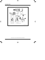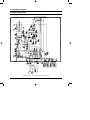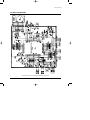
1
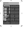
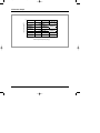
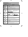
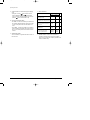
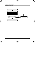
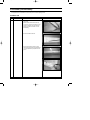
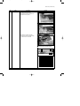
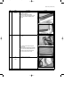
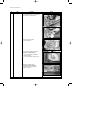
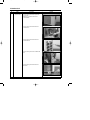
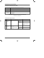
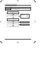
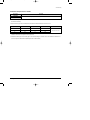
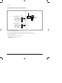
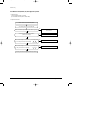
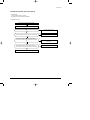
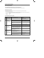
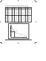
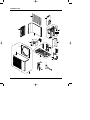
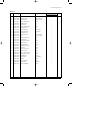
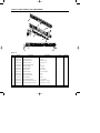
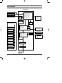
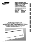
DB98-17813(1)_co
04/2/23 10:33 AM
Page 3
ROOM AIR CONDITIONER
INDOOR UNIT
OUTDOOR UNIT
SH09AI8R
SH09AI8V
SH09AI8RX
SH09AI8VX
SERVICE
AIR CONDITIONER
Manual
CONTENTS
1. Product Specifications
2. Operating Instructions
3. Disassembly and Reassembly
4. Refrigerating Cycle Diagram
5. Set Up the Model Option
6. Troubleshooting
7. Exploded Views and Parts List
8. Block Diagram
9. PCB Diagram
10. Wiring Diagram
11. Schematic Diagram
DB98-17813(1)_1
04/2/23 10:27 AM
Page 1
1. Product Specifications
1-1 Table
Model
Item
SH09AI8R / SH09AI8V
Indoor unit
Type
Wall-mounted
Cooling
Cooling
Air Volume
Heating
Cooling
Noise
( ):EUROVENT
Heating
Energy Efficiency Ratio
Cooling
Heating
Power
m3/min
dB
1.4
6.4
24
7.4
24
44(58)
52(61)
44(58)
Operating Current
Cooling
Heating
Cooling
Heating
Cooling
Power Factor
Heating
Starting Current
Length
Power Cord
52(61)
3.03
W/W
3.41
V-Hz
Power Consumption
1-220 / 240-50
890
W
850
3.9
A
3.8
98.7
%
99.9
A
21.0
m
-
Number of Core Wire
Capacity
Outer
Dimension
WxHxD
Weight
Refrigerant Pipe
Size
2.90
|/h
Dehumidifying
Power
2.70
kW
Heating
Performance
Outdoor unit
250V-10 / 16A
A
mm
760 x 410 x 147
695 x 530 x 280
inch
29.9 x 16.1 x 5.8
27.4 x 20.9 x 11.0
kg
15
28.0
Liquid
mm x L(m)
ø6.35 x 7
GAS
mm x L(m)
ø9.52 x 7
D(mm)
ø21
Drain Hose
Type
Compressor
Motor
Rotary
Type
-
Rated Output
Type
Blower
Motor
Type
Rated Output
W
Heat Exchanger
-
-
Turbo-Fan
Propeller
steel
steel
60
25
2ROW 12STEP
1ROW 24STEP
CAPILLARY TUBE
Refrigerant Control Unit
Freezer Oil Capacity
cc
Refrigerant to Change(R410A)
g
Protection Device(OLP)
-
280
590
RBC12054-12500
Cooling Test Condition
INDOOR UNIT : DB27˚C WB19˚C
OUTDOOR UNIT : DB35˚C WB24˚C
Maximum Operation Condition
INDOOR UNIT : DB32˚C WB23˚C
OUTDOOR UNIT : DB43˚C WB26˚C
Samsung Electronics
1
DB98-17813(1)_1
04/2/23 10:27 AM
Page 2
1-2 Pressure Graph
10
2
Low Pressure [kg/cm G]
30.6/22.5
9
27/19
8
21.5/14.6
7
3
20
30
40
Outdoor drybulb temperature [deg C]
2
Samsung Electronics
DB98-17813(1)_1
04/2/23 10:28 AM
Page 3
2. Operating Instructions
2-1 The Feature of Key in remote control
No
1
NAMED OF KEY
FUNCTION OF KEY
(On/Off)
On/Off button.
Press the
button to stop or run the air conditioner.
(UP)
Temperature adjustment button(UP).
To increase the temperature by the pressing the temperature button.
(DOWN)
Temperature adjustment button(DOWN).
To decrease the temperature by the pressing the temperature button.
2
3
Mode selection button.
Each time you press this button
Mode is changed in the following order
: Auto Mode
: Fan Only
: Cool Mode
: Heat Mode
: Dry Mode
Fan speed adjustment button.
Each time you press this button, FAN SPEED is changed in the following order.
4
Low
Medium
High
Automatic(rotated :
5
Swing button.
It adjusts the airflow to upward and downward, left and right.
6
Turbo button.
The air conditioner cools or heats the room as quickly as possible.
After 30minutes, the air conditioner is reset automatically to the previous mode.
7
Energy saving button.
If you wish to save energy when using your air conditioner, select the Energy saving
mode with the
button.
8
Sleep button.
The sleep timer can be used when you are cooling or heating your room to switch the
air conditioner off automatically after a period of 6 hours.
Samsung Electronics
)
3
DB98-17813(1)_1
04/2/23 10:28 AM
Page 4
Operating Instructions
No
9
10
NAMED OF KEY
FUNCTION OF KEY
Anion button.
Press the
button to generate ion from the air conditioner.
On Timer button.
The On Timer enables you to switch on the air conditioner automatically after
a given period of time that is from 30 minutes to 24 hours.
To set the operating time, press the
time display.
11
Off Timer button.
The Off Timer enables you to switch off the air conditioner automatically after
a given period of time that is from 30 minutes to 24 hours.
To set the operating time, press the
time display.
12
4
button one or more times until the required
Timer Set/Cancel button.
After setting On Timer or Off Timer, press the
And press the
13
button one or more times until the required
button to set it completely.
button again to cancel On Timer or Off Timer set.
Digital On/Off button.
If you want to turn off the display during operation press the
button.
Samsung Electronics
DB98-17813(1)_1
04/2/23 10:28 AM
Page 5
Operating Instructions
2-1-1 Name & Function of Key in remote control
1.
AUTO MODE : In this mode, operation mode(COOL,
HEAT) is selected automatically by the room temperature
of initial operation.
Room Temp
Operation Type
Tr≥ 21°C+∆T
Cool Operation (Set Temp:24˚C+∆T)
21°C +∆T>Tr
Heat Operation (Set Temp:22˚C+∆T)
∆T= -1°C, -2°C, 0°C, +1°C, +2°C
∆T is controlled by setting temperature up/down key of
remote control
2.
COOL MODE : The unit operates according to the
difference between the setting and room temperature.
(18°C~30°C)
3.
HEAT MODE : The unit operates according to the
difference between the setting and room temperature.(16°C~30°C)
*Prevention against cold wind : In order to prevent the
cool air from flowing out at the heat mode, the indoor fan
does not operate or operates very slowly in the
following cases. At this time, the indoor heat exchanger
will be preheating.
- For 3~5 minutes after the initial operation
- For deicing operation
- The operation of an indoor fan in accordance with
the temperature of an indoor heat exchanger
The temperature of
indoor heat exchanger
DRY MODE : Has 3 states, each determined by room
temperature.
The unit operates in DRY mode.
*Compressor ON/OFF Time is controlled
compulsorily(can not set up the fan speed, always
breeze).
*Protective function : Low temperature release.
(Prevention against freeze)
5.
TURBO MODE : This mode is available in AUTO, COOL,
HEAT, DRY, FAN MODE.
When this button is pressed at first, the air conditioner is
operated “powerful” state for 30 minutes regardless of the
set temperature, room temperature.
When this button is pressed again, or when the operating
time is 30 minutes, turbo operation mode is canceled and
returned to the previous mode.
*But, if you press the TURBO button in DRY or FAN
mode that is changed with AUTO mode automatically.
6.
SLEEP MODE : Sleep mode is available only in COOL or
HEAT mode.
The operation will stop after 6 hours.
*In COOL mode : The setting temperature is automatically raised by 1°C each 1hour When the
temperature
has been raised by total of 2°C, that
temperature is maintained.
*In HEAT mode : The setting temperature is automatically
dropped by 1°C each 1hour.
When the temperature has been dropped by total of 2°C,
that temperature is maintained.
7.
FAN SPEED : Manual (3 step), Auto (4 step)
Fan speed automatically varies depending on both the
difference between setting and the room temperature.
8.
COMPULSORY OPERATION :
For operating the air conditioner without the remote
control.
*The air conditioner starts up in the most suitable mode
for the room temperature:
Indoor fan speed
below 28˚C
off
28˚C~below 34˚C
LL Speed
34˚C~below 40˚C
L Speed
above 40˚C
Setting Speed
*High temperature release function : It is a function to
detect an outdoor overload by the sensor of an indoor
heat exchanger and to turn the outdoor fan or the
compressor ON/OFF for safety.
*Deice : Deicing operation is controlled by indoor unit's
heat exchanger temperature and accumulating time of
compressor's operation.
Deice ends by sensing of the processing time by deice
condition.
Samsung Electronics
4.
Room Temperature
Operating Mode
Less than 21˚C
Heat
22˚C approx.
21˚C or above
Cool
24˚C approx.
Temperature Setting
5
DB98-17813(1)_1
04/2/23 10:28 AM
Page 6
Operating Instructions
9.
SWING : BLADE-H is rotated vertically by the stepping
motor.
*Swing Set : Press the
button under the remote
control is displayed on LCD the
and the blades
move up and down, left and right. If the one more time
press the
button, blades location is stop.
10. SETTING THE ON/OFF TIMER. :
*ON TIMER : The On Timer enables you to switch on the
air conditioner automatically after a given period of time.
You can set the period of time from 30 minutes to 24
hours.
*OFF TIMER : The Off Timer enables you to switch off
the air conditioner automatically after a given period of
time. You can set the period of time from 30 minutes to
24 hours.
11. GENERATING ANION :
The air conditioner can generate anion with an ionizer in
the indoor unit.
6
12. SELF DIAGNOSIS
Error Mode
DISPLAY 7-SEGMENT
Remark
Operation Off Operation On
Indoor unit room temperature sensor
error (open or short)
OFF
E1
Indoor unit heat exchanger
temperature sensor error(open or short)
OFF
E2
Indoor FAN MOTOR error :
Keep the RPM value 450 below for
15 seconds
OFF
E3
EEPROM error
OFF
E6
All lamp
blinking
All lamp
blinking
Error in option
In case of No option set-up
In case of option data error
13. BUZZER SOUND : Whenever the On/Off button is
pressed or whenever change occurs to the condition
which is set up or select, the compulsory operation mode,
buzzer is sounded "beep".
Samsung Electronics
DB98-17813(1)_1
04/2/23 10:28 AM
Page 7
2-2 Replace PCB Model option
2-2-1 Replace PCB model option
Remove power cord
Replace the PCB module
Check the connection and plug in
No
Does all display lamp blink?
Replace another PCB
Yes
Refer to set up the Model option(16~17page)
Samsung Electronics
7
DB98-17813(1)_1
04/2/23 10:28 AM
Page 8
3. Disassembly and Reassembly
Stop operation of the air conditioner and remove the power cord before repairing the unit.
3-1 Indoor Unit
No
Parts
1
Front Grille
Procedure
Remark
1) Stop the air conditioner and shut off the
main power.
2) Hold the knobs on both sides of the Top
Cover. Then, pull the cover toward you and
lift it up to separate it from the main body.
(Please push down the bottom cover for
disassembly.)
3) Unscrew the Main PCB Cover.
4) Loosen the Panel fixing screws on both
sides of the bottom Panel and pull down the
cover and separate the projection from the
groove.
8
Samsung Electronics
DB98-17813(1)_1
04/2/23 10:28 AM
Page 9
Disassembly and Reassembly
No
Parts
Procedure
Remark
● Loosen
the pipe bush screws.
(Pull down the cover and separate the
projection from the groove.)
5) Separate the 2 grille driving Motor
Connectors and one receiving sensing
connector from the main PCB.
<Main PCB Connector Illustration Drawing>
! @
#$
)
^
%
No
!
@
#
$
%
^
&
*
(
)
Samsung Electronics
&* (
Connector Parts
Fan Motor(L)
Fan Motor(R)
Wing Motor(L)
Wing Motor(R)
Wing Motor(B)
Room Temperature/Piping Sensor
Grille Driving Motor(L)
Grille Driving Motor(R)
Mark/Receiver
Anion
9
DB98-17813(1)_1
04/2/23 10:28 AM
Page 10
Disassembly and Reassembly
No
Parts
Procedure
Remark
6) Loosen the 4 fixing screws.
7) Detach the Panel.
● Cautions
for Panel Assembly
Put the separated connectors in the right
position respectively.
● - Please avoid suppression of wires or
deviation of power cords and cross room
power connection cables. (For details, refer
to the Indoor Unit Connection
Cable Installation.)
●-
2
MAIN PCB
1) Loosen the fixing screws on
both sides of the Electric Component Box.
2) Detach all the connectors for the main PCB.
● Cautions
for Connectors Assembly
sure to put connectors in the right
position.
● Be
3) Loosen the fixing screws on both sides of
the Electric Component Box.
4) Loosen the grounding screws.
10
Samsung Electronics
DB98-17813(1)_1
04/2/23 10:28 AM
Page 11
Disassembly and Reassembly
No
Parts
3
Basket
Procedure
Remark
1) Loosen the 3 fixing screws.
2) Detach the Basket.
● Cautions
for Basket Assembly
sure to check if the projection on both
sides was positioned completely in the
groove.
● Be
4
Heat Exchanger
1) Loosen the 3 Heat Exchanger fixing
screws.
2) Lift up the Heat Exchanger slightly for
disassembly.
● Cautions
for Heat Exchanger Assembly
allow the insulating materials to be
damaged or the piping to be deformed
during disassembly and assembly.
● Never
5
Fan
&
Motor
Samsung Electronics
1) Loosen the 6 cover screws.
11
DB98-17813(1)_1
04/2/23 10:28 AM
Page 12
Disassembly and Reassembly
No
Parts
Procedure
Remark
2) Loosen the bottom wing screws to detach
the assembly. (one fixing screw)
3) Detach the Fan fixing bolts.
(with a M3 wrench)
4) Loosen the 3 Fan Motor fixing screws.
● Cautions
for Motor Assembly
Do not miss the Motor anti-vibration
rubber and washer.
● - Do not miss the Motor wire fixing cover.
●-
5) Detach the Negative Ionizer.
● Cautions
for Ionizer Assembly
allow the deformation of the
Negative Ionizer pin.
● Never
12
Samsung Electronics
DB98-17813(1)_1
04/2/23 10:28 AM
Page 13
3-2 Outdoor Unit
No
Parts
1
Common Work
Procedure
Remark
1) Loosen 2 fixing screws and separate the
Cover Valve.
2) Detach the connection wire from the
Terminal Block.
3) Loosen 4 fixing screws and detach the
Cabinet Front.
4) Loosen 2 fixing screws and detach the
Cabinet-Side LF.
5) Loosen 2 fixing screws of the Cabinet-Side
RH.
6) Loosen 2 fixing screws and detach the
Bar Steel.
Samsung Electronics
13
DB98-17813(1)_1
04/2/23 10:28 AM
Page 14
Disassembly and Reassembly
No
Parts
2
Fan
&
Motor
Procedure
Remark
1) Detach the connection wire of the Motor
Fan.
2) Remove the Nut Flange.
(Turn to the clockwise)
3) Detach the Fan.
4) Loosen 4 fixing screws to detach
the Motor.
5) Loosen 4 fixing screws and detach the
Motor Bracket from the Base.
14
3
Heat Exchanger
1) Loosen 2 fixing screws of left and right
side.
2) Disassemble the inlet and outlet pipe by
welding.
3) Detach the Heat Exchanger.
4
Compressor
1) Open the Terminal Cover of Compressor
and unscrew the Connection Terminal.
2) Disassemble the inlet and outlet pipe of
Compressor by welding.
3) Loosen 3 fixing bolts of the lower part.
4) Detach the Compressor.
Samsung Electronics
DB98-17813(1)_1
04/2/23 10:29 AM
Page 15
4. Refrigerating Cycle Diagram
Outdoor Unit
Indoor Unit
Capillary tube
T1
2-Way valve
Heat
Exchanger
(Evaporator)
Heat
Exchanger
(Evaporator)
Propeller Fan
Turbo Fan
Liquid side
T2
Gas side
3-Way valve
4-Way valve
Cooling
Compressor
Heating
Gas leak check point
Samsung Electronics
15
DB98-17813(1)_1
04/2/23 10:30 AM
Page 16
5. Set Up the Model Option
5-1 Setting Option Setup Method
Option No. :
(SH09AI8R / SH09AI8V)
Step 1 : Enter the Option Setup mode.
1st
Take out the batteries of remote control.
2nd
Press the temperature
insert the battery again.
3rd
Make sure the remocon display shown as
button simultaneously and
.
Step 2 : Enter the Option Setup mode and select your option according to the following procedure.
1
The default value is
Otherwise, push the
.
button to
.
Every time you push the button, the display panel reads
or
repeatedly.
2
Push the
3
3
Push the
4
5
.
Every time you push the button, the display panel reads
...
repeatedly.
2
1
button to set the display panel to
button to set the display panel to
.
Every time you push the button, the display panel reads
...
repeatedly.
6
4
Push the
button to set the display panel to
.
Every time you push the button, the display panel reads
...
repeatedly.
5
Push the
button to set the display panel to
.
Every time you push the button, the display panel reads
...
repeatedly.
6
✳ Setting is not required if you must
a value which has a
default.
16
Push the
button to set the display panel to
.
Every time you push the button, the display panel reads
...
repeatedly.
Samsung Electronics
DB98-17813(1)_1
04/2/23 10:31 AM
Page 17
Set Up the Model Option
7
The default value is
Otherwise, push the
.
button to
.
Every time you push the button, the display panel reads
or
repeatedly.
8
Push the
9
7
.
9
Push the
10
11
button to set the display panel to
Every time you push the button, the display panel reads
...
repeatedly.
8
button to set the display panel to
.
Every time you push the button, the display panel reads
...
repeatedly.
12
10
Push the
button to set the display panel to
.
Every time you push the button, the display panel reads
...
repeatedly.
11
Push the
button to set the display panel to
.
Every time you push the button, the display panel reads
...
repeatedly.
12
Push the
✳ Setting is not required if you must
a value which has a
default.
button to set the display panel to
.
Every time you push the button, the display panel reads
...
repeatedly.
Step 3 : Upon completion of the selection, check you made right selections.
Press the Mode Selection key,
The display part shows
Press the Mode Selection key,
The display part shows
to set the display part to
and check the display part.
.
to set the display part to
and check the display part.
.
Step 4 : Pressing the ON/OFF button (
)
When pressing the operation ON/OFF key with the direction of remote controller for unit, the sound ''Ding'' or ''Diriring'' is
heard and the OPERATION ICON(
) lamp of the display is flickering at the same time, then the input of option is completed. (If the diriring sound isn't heard, try again pressing the ON/OFF button.)
Step 5 : Unit operation test-run
First, Remove the battery from the remote controller.
Second, Re-insert the battery into the remote controller.
Third, Press ON/OFF key with the direction of remote controller for set.
• Error Mode
1st If all lamps of indoor unit are flickering, Plug out, plug in battery again and press ON/OFF key to retry.
2nd If the unit is not working properly or all lamps are continuously flickering after setting the option code, see if the correct option code is
set up for its model.
Samsung Electronics
17
DB98-17813(1)_1
04/2/23 10:31 AM
Page 18
6. Troubleshooting
Check the basic items first to judge if the problem was caused by breakdown or misuse. If none of the basic items are related to the
problem, please scrutinize the machine according to the 'Breakdown Diagnosis by Symptoms' method.
6-1 Basic Breakdown Diagnosis Items
1. Is power supply right?
The power supply shall be within ±10% of the input voltage.
Otherwise, the machine may fall in abnormal operation.
2. Is the indoor unit connected with the outdoor unit?
3. The following symptoms are not categorized in the breakdown.
Symptoms
Inoperative
- Power failure or plugged-out?
- Wasn't the reserved operation period over?
- Take out the batteries of remote control and put them in it one minute later.
Then put the remote control in operation again.
- Plug out and plug in 10 seconds later.
No cool wind
- Isn't the dust collecting filter clogged with dust or stained?
- Isn't there any direct ray or obstacle to the outdoor unit?
- Is the temperature setting value too high? If so, please turn it down.
- Isn't the air conditioner in wind-only operation?
Strange smell
- Please ventilate the room because the smell penetrated into the wall or furniture is not
coming out as the air conditioner begins operating.
- Check if the dust collecting filter is stained.
Inoperative remote
control
- Aren't batteries dead?
- Aren't batteries wrongly positioned?
- Isn't the indoor unit sensor covered?
- Isn't the electric wave blocked by neon-signs or electronic fluorescent lamps?
Unable to control
air volume
- Is the operation mode in one of AUTO, DEHUMID, or TURBO?
Then, no further control is required because the air volume will be automatically controlled.
- Please return to the COOL/WIND mode to recheck the condition.
Unable to reserve
- Please check if you pressed the OK/CANCEL button after you set the reservation time.
Unable to set
temperature
Water leak
(from indoor unit)
18
Reasons
- Isn't the operation mode in TURBO?
Then, no further control is required because the air volume will be automatically controlled.
- Please return to the COOL mode to recheck the condition.
- Check the refrigerant pressure. (to check refrigerant leak)
- Is the indoor unit so installed that water is smoothly drained?
- Aren't the drain outlet and hose clogged?
- Please re-vacuum and recharge refrigerant.
(Insufficient refrigerant distribution may prevent water from forming on the evaporator.)
Samsung Electronics
DB98-17813(1)_1
04/2/23 10:31 AM
Page 19
6-2 Trouble check in the initial status
6-2-1 Diagnosis and marking of the part in trouble.
Please check the air conditioner operation status and write the check result in the chart in the room.
7-SEGMENT Mark
Error Part
E1
Indoor unit Temperature Sensor Error(SHORT/OPEN)
E2
Indoor unit Piping Sensor Error(SHORT/OPEN)
E6
EEPROM Error(Option Memory)
- Option Error
All Lamp Off
- Option Unselected
- Option Data Error
The motor RPM is not sensible because the indoor fan motor has no feedback sensor.
Therefore, there is no fan motor error.
6-2-2 Operation with abnormal motion
NO
Abnormal condition
1
No response from the
remote control operation signal.
2
Unable to operate the
outdoor unit
Samsung Electronics
Inspection
1) Plug out and plug in 5 seconds
later.
1) Press the TURBO button with the
remote control.
2) In 3 minutes, check the voltage
between the indoor unit terminal
block N and L.
Initial Diagnosis
Able to operate the
remote control
OK
Unable to operate
the remote control
Press the AUTO button in the indoor
unit.
(1) If it operates, the remote control
and indoor unit receiver are in
trouble.
(2) If not, the indoor unit is in trouble.
AC198V ~ AC242V
Problem with the outdoor unit or PCB
No power source
displayed.
Problem with the relay (RY71) or PCB
19
DB98-17813(1)_1
04/2/23 10:31 AM
Page 20
6-3 Breakdown diagnosis by symptoms
6-3-1 Indoor unit temperature sensor failure
Error Part
Error mark
7-SEGMENT
Indoor unit temperature sensor open or short
E1
Detach the assembly sensor from the ASS'Y PCB
CN43 connector and measure the sensor resistance
with an ohmmeter (tester).
Is the sensor resistance value 10KΩ ±1,2KΩ at the
room temperature of 25˚C?
No
Yes
ASS'Y Sensor Replace
SENSOR Resistance Value : 20˚C-12.09kΩ
SENSOR Resistance Value : 30˚C-8.31kΩ
SENSOR Resistance Value : 35˚C-6.94kΩ
SENSOR Resistance Value : 40˚C-5.83kΩ
Connect the sensor to CN43, supply power, and measure
the voltage of #1 and #2 of the CN43 connector.
Below 1.3V?
Yes
Poor ASS'Y PCB Replace
No
Over 3.7V?
Yes
Poor ASS'Y PCB Replace
No
MICOM Error, MICOM Replace
20
Samsung Electronics
DB98-17813(1)_1
04/2/23 10:31 AM
Page 21
Troubleshooting
6-3-2 Indoor unit Pipe Sensor in Trouble
Error mark
7-SEGMENT
Error Part
Indoor unit Heat exchange temperature sensor open or short
E2
1. Check the assembly condition of the sensor connector(CN43) on the indoor unit Main PCB and if not assembled, reassemble
the connector accurately.
2. Detach the indoor pipe sensor connector(CN43) and check the resistance between connector 3 and 4.
Temperature(˚C)
Resistance Value (KΩ)
Temperature(˚C)
Resistance Value (KΩ)
15
8.31
30
8.31
20
6.94
35
6.94
25
5.83
40
5.83
OTHERS
The data error is ±1%.
If the above data is not met, replace the indoor pipe sensor.
3. Assemble the indoor pipe sensor to PCB, plug in, and check the voltage of connector 3 and 4. If the resistance is below 0.5V or
over 4.9V, replace the indoor Main PCB (PCB phase short or disconnected)
Samsung Electronics
21
DB98-17813(1)_1
04/2/23 10:31 AM
Page 22
Troubleshooting
6-3-3 When the Indoor unit fan motor doesn't operate
AC220V
Red
MOTOR
Yellow
Green
Indoor Unit Fan Motor(L)
12V
CR71
1.2µF/450V
Yellow
Green
0V
12V
MICOM
#32
!
#
Operating Condenser
IC07
%
CN74
White
Red
MOTOR
SSR
+
CN73
Blue
Indoor Unit Fan Motor(R)
60Hz
CR72
1.2µF/450V
!
#
Operating Condenser
%
1. Check if power(AC220V) is being supplied.
2. Check if the operating condenser(CR71, CR72) and connector(CN73, CN74) are properly assembled.
3. Put the fan in operation with the remote control and check if the fan is rotating after the auto grille is full open.
(If so, it is in norma operation)
4. If not, measure AC voltage of No. 5 and 3 of CN73, CN74.
• If the voltage value is 180~220V : Poor motor
• If not : Poor PCB
22
Samsung Electronics
DB98-17813(1)_1
04/2/23 10:31 AM
Page 23
Troubleshooting
6-3-4 When the power doesn't come in.
1. Pre-inspection Items
1) Power voltage (AC198V ~ AC242V)
2) Power cable connection
3) Check if the standard lamp(in blue) of the display part twinkles with a bang sound when you supply power.
If not, please check the fan according to the following procedure.
2. Inspection Procedure
1) Checking the main PCB power
(1) Check if the power cable connector(in black or white) were normally assembled.
• White : to the N(1) terminal of the terminal block
• Black : to terminal 1 of PCB
(2) Check if the outdoor power cable connector were normally assembled.
• White : to the N(1) terminal of the terminal block
• Black : to terminal 1 of the terminal block
(3) Check if the PCB fuse(F701, 250V 3.15A) is disconnected.
(4) Check the output voltage of the static voltage IC.
• KA78L05(IC02) : DC4.7 ~ 5.3V
➞ If no DC power source was output from the above items, PCB should be replaced.
2) Checking outdoor unit power supply
(1) Press the TURBO button with the remote control.
- In 3 minutes, check the outdoor unit(compressor/outdoor fan) is operating.
- If not, check the voltage of both black and white cable of the outdoor unit power supply connector. (AC198V ~ AC242V)
(2) Supply AC 220V to the outdoor unit forcibly.
(3) If the outdoor unit has no motion, check the outdoor unit and surrounding connection cables.
(4) If the outdoor starts operation, check the indoor unit connection and PCB.
Samsung Electronics
23
DB98-17813(1)_1
04/2/23 10:31 AM
Page 24
Troubleshooting
6-3-5 When louvers(bottom, left, and right) don't operate
1. Inspection Items
1) Power Voltage (AC198V ~ AC242V)
2) Louver Motor Connector(CN61, CN62, CN65)
2. Inspection Procedure
Check if louvers have mechanical problem.
Turn off the power and on 5 seconds later.
No
Does the standard lamp twinkle 3 minutes before it goes out?
It happens when th power
doesn't come in
Yes
Are all the louvers open during operation?
(bottom, left, and right)
Yes
Not a breakdown(normal)
No
Does the GND voltage of connector 2, 3, 4, and 5 range from
DC 6V to 8V? (when louvers are operating)
Yes
Checking motor connection, Poor motor
No
Does the GND voltage of connector 2, 3, 4, and 5 range from
DC 12V? (when louvers are operating)
Yes
PCB Replace
No
Checking connection and apparatus assembly condition.
24
Samsung Electronics
DB98-17813(1)_1
04/2/23 10:31 AM
Page 25
Troubleshooting
6-3-6 When the automatic grille doesn't operate.
1. Inspection Items
1) Power Voltage (AC198V ~ AC242V)
2) Assembly of Connector between both Motors
2. Inspection Procedure
Check if louvers have mechanical problem.
Turn off the power and on 5 seconds later.
No
Does the standard lamp twinkle 3 minutes before it goes out?
It happens when the power
doesn't come in
Yes
Yes
Are both auto grilles open during operation? (left and right)
Not a breakdown(normal).
No
Does the GND voltage of connector(CN63, CN64) 2, 3, 4
and 5 range from DC 6V to 8V? (when louvers are operating)
Yes
Checking motor connection,
Poor motor
No
Does the GND voltage of connector(CN63, CN64) 2, 3, 4
and 5 range from DC 12V? (when louvers are operating)
Yes
PCB Replace
No
Checking connection and apparatus assembly condition.
Samsung Electronics
25
DB98-17813(1)_1
04/2/23 10:31 AM
Page 26
Troubleshooting
6-3-7 When the remote control is not receiving.
1. Check the remote control quality with a remote control receiving tester.
2. Check if the connector was normally assembled.
3. Put the set in operation and check the voltage of No. 1(+) and No. 3(-) of the main PCB CN 94 while operating the remote
control. When the voltage descends below 3V, the assembly module PCB is normal and the main PCB is poor. Then replace the
main PCB.
4. Replace the assembly display PCB because the module PCB is poor if the voltage between No. 1, 2, and 3 of CN 94 maintains
5V after the remote control starts operation.
26
Samsung Electronics
DB98-17813(1)_1
04/2/23 10:31 AM
Page 27
6-4 PCB Inspection Method
6-4-1 Pre-inspection Notices
1. Check if you pulled out the AC power plug when you eliminate the PCB or front panel.
2. Don't hold the PCB side not to impose excessive force on it to eliminate the PCB.
3. Don't pull the lead wire but hold the whole housing to connect or disconnect a connector to the PCB.
6-4-2 Inspection Procedure
1. Check connector connection and peeling of PCB or bronze coating pattern before you think the PCB is broken.
2. The PCB is composed of the 3 parts.
• Main PCB Part : MICOM and surrounding circuit, relay, room fan motor driving circuit and control circuit, sensor driving circuit,
power circuit of DC12V and DC5V, and buzzer driving circuit
• Display part : LED lamp
• Switch part
: Switch
6-4-3. Detailed Inspection Procedure
NO
Procedure
1
Plug out and pull the PCB
out of the electronic box.
1) Is the fuse disconnected? (F701)
2
Check the PCB fuse.
supply power.
If the standard lamp
twinkles at this time, the
above 1) ~ 3) have no
relation.
Checking the power voltage.
3
4
Press the OPER/STOP
button one time to enter
the TURBO mode.
But, exclude the
RESERVE operation.
Press the OPER/STOP
button one time to enter
the OPER mode.
1. Air Volume[High]
2. Continuous Operation
Samsung Electronics
Inspection Method
Cause
• Overcurrent
• Room Fan Motor Short
• ASS'Y Main PCB AC Pattern Short
1) Is the BD71input voltage AC198V~AC242V?
• Poor Power Cord, Fuse Disconnection,
Wrong Power Cable Wiring, Poor AC Part
2) Is the voltage between both terminals of the output
C104 on the 2nd side of the transformer AC12V
±0.5V?
• Poor Switching Trans, Poor Power Circuit
3) Is the voltage between both terminals of OUT and
GND of IC02(KA78L05) DC5V ±0.5V?
• Poor Power Circuit, Load Short
Checking the power voltage.
1) Check the voltage of the relay(RY71) coil(IC05 PIN
#10 and GND : OV, PIN#7 and GND : 5V) during
operation(3 minutes after TURBO operation).
• Relay(RY71) Coil Disconnection, Poor IC05
2) Check the voltage of both terminals of
terminal block 1 and N(1) after 3 minute
operation.: AC220V
• Poor Relay(RY71) Contact
1) Is the voltage over AC180V being imposed on terminal #3 and #5 of the room fan motor
connector(CN73 and CN74)?
• Poor Room Fan Motor
2) The room fan motor doesn't run.
• Poor Room Fan Motor Connector
(CN73 and 74) Contact
3) The power voltage between terminal #3 and #5 of
the connector(CN73 and CN74) is 0V.
• Poor ASS'Y Main PCB
• Poor Connection
27
DB98-17813(1)_1
04/2/23 10:31 AM
Page 28
Troubleshooting
6-4-4 Temperature Sensor Feature Conversion Table(Room Temperature Sensor); 103AT
Temperature Sensor Resistance Temperature Sensor Resistance Temperature Sensor Resistance Temperature Sensor Resistance
[˚C]
[˚C]
[˚C]
[˚C]
[Kohm]
[Kohm]
[Kohm]
[Kohm]
70
69
68
67
66
65
64
63
62
61
60
2.229
2.296
2.365
2.437
2.512
2.589
2.669
2.752
2.838
2.928
3.021
49
48
47
46
45
44
43
42
41
40
4.300
4.444
4.594
4.749
4.912
5.080
5.256
5.439
5.630
5.828
29
28
27
26
25
24
23
22
21
20
8.622
8.944
9.281
9.632
10
10.380
10.780
11.200
11.630
12.090
9
8
7
6
5
4
3
2
1
0
18.700
19.480
20.290
21.150
22.050
22.990
23.900
25.030
26.130
27.280
59
58
57
56
55
54
53
52
51
50
3.116
3.216
3.319
3.426
3.537
3.652
3.772
3.897
4.026
4.161
39
38
37
36
35
34
33
32
31
30
6.033
6.246
6.468
6.699
6.941
7.192
7.455
7.729
8.015
8.313
19
18
17
16
15
14
13
12
11
10
12.560
13.060
13.570
14.120
14.680
15.280
15.900
16.550
17.240
17.960
-1
-2
-3
-4
-5
-6
-7
-8
-9
28.470
29.720
31.040
32.430
33.890
35.430
37.050
38.760
40.560
<Temperature Sensor Characteristic Curve>
Temperature
(˚C)
70
60
50
40
At the temperature of
25˚C(10KΩ)
30
20
10
0
-10
-9
5
28
10
15
20
25
30
35
40
Resistance Value (Kohm)
Samsung Electronics
DB98-17813(1)_1
04/2/23 10:31 AM
Page 29
6-5 Main Part Inspection Method
Breakdown Inspection Method
Part
Room Temperature Sensor
Measure resistance with a tester
Normal
Abnormal
Room Fan Motor
Abnormal
Abnormal
Normal
Abnormal
Resistance
Remark
Yellow, Blue
404.4Ω±10%
Main
Yellow, Red
340Ω±10%
Sub
∞, 0Ω . . . Open or Short
At the normal temperature (10˚C ~ 30˚C)
Compare terminal
Resistance
Remark
Yellow, Red
360Ω±10%
Main
Black, Yellow
328Ω±10%
Sub
∞, 0Ω . . . Open or Short
About 300 Ω at the normal temperature (20˚C ~ 30˚C)
∞, 0Ω . . . Open or Short
Measure the resistance between connector 3 and each terminal wire with a tester.
(Grille Motor)
Normal
Abnormal
Samsung Electronics
Compare terminal
Measure the resistance between the red wire and each terminal wire with a tester.
(Discharge Louver : B/L/R)
Stepping Motor
At the normal temperature (10˚C ~ 30˚C)
Measure the resistance between motor wires with a tester.
Normal
Stepping Motor
∞, 0Ω . . . Open or Short
Measure the resistance between terminals of the connector (CN73) with a tester.
Normal
Outdoor Fan Motor
At the normal temperature 37kΩ~ 8.3kΩ(-7˚C~+30˚C) *Refer to Table 6-4-4.
About 120 Ω at the normal temperature (20˚C ~ 30˚C)
∞, 0Ω . . . Open or Short
29
DB98-17813(1)_1
04/2/23 10:32 AM
Page 30
7. Exploded Views and Parts List
7-1 Indoor Unit
6
1-8
1-11
1-13
1-12
1-9
1-1
1-10
1
1-4
1-2
1-3
1-5
1-4
1-6
1-7
1-14
7
2
5-1
3
5-4
4
8-3
5-2
5
5-3
5-5
8-1
8-4
8-6
8-4
8-5-1
8-5-2
8-3
8-8
8
8-2
8-11
8-7
13
8-9
11
8-10
10
12
9
You can search for the updated part code
number through the ITSELF.
URL : http://itself.sec.samsung.co.kr
30
Samsung Electronics
DB98-17813(1)_1
04/2/23 10:32 AM
Page 31
Exploded Views and Parts List
■
Parts List
No.
Code No.
Description
Q'TY
Specification
SH09AI8R
Remark
SH09AI8V
1
DB94-00291E
ASS'Y BACK BODY
ASS'Y
1
1
1-1
DB94-00296A
ASS'Y BACK BODY INSULATION
HIPS,ASS'Y
1
1
1-2
DB32-00182B
MOTOR FAN LF
ASS'Y
1
1
1-3
DB32-00182A
MOTOR FAN RH
ASS'Y
1
1
1-4
DB61-01301A
HOLDER WIRE
SGCC-M,T0.8
2
2
1-5
DB31-00174A
TURBO FAN LF
AS+G/F
1
1
1-6
DB31-00173A
TURBO FAN RH
AS+G/F
1
1
1-7
DB91-00265A
ASS'Y IONIZER
ASS'Y
1
1
1-8
DB92-00374A
ASS'Y BLADE SIDE
ASS'Y
1
1
1-9
DB92-00372A
ASS'Y BLADE LOW
ASS'Y
1
1
1-10
DB69-00692A
CUSHION BODY
EPS
1
1
1-11
DB63-00682A
COVER BODY LF
HIPS
1
1
1-12
DB63-00683A
COVER BODY RH
HIPS
1
1
1-13
DB70-00452A
PLATE-WIRE HOLDER
ASS'Y
1
1
1-14
DB94-00289B
ASS'Y BELL MOUTH
ASS'Y
1
1
2
DB96-02579B
ASS'Y EVAP
ASS'Y
1
1
3
DB94-00286A
ASS'Y TRAY DRAIN
ASS'Y
1
1
4
DB94-00315D
ASS'Y DRAIN HOSE
ASS'Y
1
1
5
DB93-01816A
ASS'Y CONTROL IN
ASS'Y
1
1
5-1
DB63-00673A
COVER MAIN PCB LOW
ABS
1
1
5-2
DB93-01518B
ASS'Y PCB MAIN AC
ASS'Y
1
1
5-3
DB93-01519B
ASS'Y PCB MAIN DC
ASS'Y
1
1
5-4
DB65-00125A
ASS'Y TERMINAL BLOCK
ASS'Y
1
1
5-5
DB32-00020A
ASS'Y THERMISTOR-WIRE
ASS'Y
1
1
6
DB70-00317A
HANGER-PLATE
SGCC-M
1
1
7
DB61-01291A
HOLDER PIPE
HIPS
1
1
8
DB92-00371V
ASS'Y PANEL FRONT
SATIN SILVER
-
1
8-1
8-2
8-3
DB92-00371U
ASS'Y PANEL FRONT
TROPICAL RED
1
-
DB64-00784A
PANEL FRONT UP
HIPS
1
1
1
DB90-01115V
ASS'Y COVER Grille SERVICE
SATIN SILVER
-
DB90-01115U
ASS'Y COVER Grille SERVICE
TROPICAL RED
1
-
DB31-00166A
MOTOR STEPPING
2VDC 35PM412BN
1
1
8-4
DB94-00292A
ASS'Y GEAR PINION
ASS'Y
1
1
8-5-1
DB63-00420A
FILTER BIO
-
1
1
8-5-2
DB63-00616C
FILTER DEODORIZATION
-
1
1
8-6
DB63-00387B
COVER FILTER UP
ABS
1
1
8-7
DB63-00684A
GUARD AIR FILTER
ABS
1
1
8-8
DB39-00816B
ASS'Y C/W STEP MOTOR(LEFT)
ASS'Y
1
1
8-9
DB93-01520A
ASS'Y DISPLAY PCB
ASS'Y
1
1
8-10
DB93-01536A
ASS'Y C/W DISPLAY&S/W
ASS'Y
1
1
8-11
DB39-00816A
ASS'Y C/W STEP MOTOR(RIGHT)
ASS'Y
1
1
9
DB63-00679A
COVER MAIN PCB UP
ABS
1
1
10
DB92-00368A
ASS'Y PANEL LOW
ASS'Y
1
1
11
DB63-00681A
COVER DECO UP
HIPS
1
1
12
DB90-01014B
ASS'Y COVER DECO LOW
ASS'Y
1
1
13
DB93-02531R
ASS'Y-REMOCON
ARH-1314
1
1
Samsung Electronics
31
DB98-17813(1)_1
04/2/23 10:32 AM
Page 32
7-2 Outdoor Unit
8
9
5-2 5-3
6
5
5-5
5-7
18
5-4
5-1
2
10
3
4-2
1
7-1
17
16
7-2
5-6
4-1
15
13
14
7
7-3
11
12
4
32
Samsung Electronics
DB98-17813(1)_1
04/2/23 10:32 AM
Page 33
Exploded Views and Parts List
■
Parts List
No.
Code No.
Description
Specification
Q'TY
Remark
SH09AI8RX /SH09AI8VX
1
DB60-30020A
NUT FLANGE
2C,M6,SM20C,NTR
1
2
DB67-50063A
FAN PROPELLER
AS+G/F 20%, ø405
1
3
DB31-10058C
MOTOR FAN OUT
220/240V,50/60Hz
1
4
DB90-01338A
ASS'Y CABINET FRONT
ASS'Y
1
4-1
DB64-00648A
CABINET FRONT
PP
1
4-2
DB61-01113A
BELL MOUTH
PP
1
5
DB90-01333B
ASS'Y CABINET SIDE RH
ASS'Y
1
5-1
DB64-00650A
CABINET SIDE RH
PP
1
5-2
2501-001238
CAPACITOR-COMP
40uF/450VAC
1
5-3
2301-001375
CAPACITOR-MOTOR
1.5uF/450VAC
1
5-4
DB65-40049E
TERMINAL BLOCK
4P
1
5-5
DB93-01547D
ASS'Y LEAD WIRE
Samsung COMPor
1
5-6
DB35-00028A
OLP
RBC 12054-12500
1
5-7
DB33-00049A
ASS'Y SOLENOID COIL
ASS'Y
1
6
DB64-00649A
CABINET SIDE LF
PP
1
7
DB90-01056F
ASS'Y BASE OUTDOOR
ASS'Y
1
7-1
DB61-01322A
BRACKET VALVE
GALVA
1
7-2
DB61-00802A
BRACKET MOTOR
SGCC-M
1
7-3
DB73-00070A
GROMMET-ISOLATOR
NR
3
8
DB71-00085A
BAR STEEL
HSWR
1
9
DB90-00947A
ASS'Y COVER VALVE
ASS'Y
1
10
DB94-00500A
ASS'Y PARTITION
ASS'Y
1
11
DB96-03011A
ASS'Y TUBE 4WAY VALVE
ASS'Y
1
12
DB96-03277A
ASS'Y TUBE CAPILLARY
ASS'Y
1
13
G4A091JU1EP
COMPRESSOR
G4A091
1
14
DB60-30028A
NUT WASHER
HEX2CM8ZPC
3
15
DB63-20002A
GASKET
EPDM
1
16
DB63-10165D
COVER TERMINAL
POM
1
17
DB60-30018A
NUT FLANGE
M5,SM20C
1
18
DB96-03110A
ASS'Y CONDENSER
ASS'Y
1
Samsung Electronics
33
DB98-17813(1)_1
04/2/23 10:32 AM
Page 34
7-3 Ass'y Control In(Indoor Unit) : DB93-01816A
■
Parts List
No.
Code No.
1
DB93-01518B
ASS'Y MAIN-PCB AC
220x45
1
2
DB93-01519B
ASS'Y MAIN-PCB DC
160x45
1
3
DB63-00673A
COVER-MAIN-P-LOW
ABS(V0) BLACK
1
4
DB61-01290A
HOLDER-CLAMP-IN
SGCC-M, Z T1.0
1
5
DB65-00125A
ASS'Y TERMINAL-BLOCK
4P
1
6
6001-000929
SCREW-MACHINE
PH M3xL20
1
7
6001-000035
SCREW-MACHINE
TH M4xL8
1
8
DB65-10074E
CABLE-CLAMP
DA-5N, NK-5N
1
9
6002-000534
SCREW-TAPPING
PH, 3x8, ZPC(BLK)
3
10
DB32-00020A
ASS'Y THERMISTOR
103AT
1
11
DB93-01554A
WIRE CONNECT JUMP
10P
1
12
6009-001001
SCREW-SPECIAL
M4xL8
2
13
DB39-00148B
WIRE CONNECT EARTH
L=100, AWG#16
1
14
DB62-01636F
SEAL-COVER MAIN PCB LOW A
FLOCKED, T0, 4, 27x45
1
15
DB62-01636G
SEAL-COVER MAIN PCB LOW B
FLOCKED, T0, 4, 86x22
1
34
Description
Specification
Q'TY
Remark
Samsung Electronics
DB98-17813(1)_1
04/2/23 10:32 AM
Page 35
8. Block Diagram
CONTROLLER
IC-MCU
HEAT EXCHANGER SENSOR
• BLADE CONTROL (down/left/right)
• AUTO GRILLE CONTROL
• INDOOR FAN MOTOR CONTROL
(left/right)
ROOM TEMPERATURE SENSOR
DISPLAY PART
• COMPRESSOR CONTROL
INFRARED SIGNAL
• TEMPERATURE CONTROL
RESET
CIRCUIT
• TIMER
• BUZZER CONTROL
TURBO
STANDARD
AVOID
TIMER
TEMPERATURE(88˚C)
OSCILLATION
CIRCUIT
ZERO
VOLTAGE
DETECT
REMOTE CONTROLLER
• COMPRESSOR CONTROL
SIGNAL
POWER ON/OFF
• STEPPING MOTOR
CONTROL SIGNAL
• BUZZER CONTROL SIGNAL
MODE
(AUTO, COOL, DRY,
FAN, HEAT)
TRIGGER
SIGNAL
INDOOR FAN MOTOR
(left/right)
SSR
COMPRESSOR
OUTDOOR FAN MOTOR
TURBO OPERATION
FAN SPEED SELECT
(H/M/L)
• COMPRESSOR DRIVE
• OUTDOOR FAN MOTOR
DRIVE
• STEPPING MOTOR DRIVE
• BUZZER DRIVE
BLADE-H
MOVING SELECT
BUZZER
STEPPING MOTOR
-Blade
(down/left/right)
-Auto grille
(left/right)
ON, OFF TIMER
SELECT
TEMPERATURE
SELECT
DC 5V
VOLTAGE REGULATOR
SLEEP SELECT
DC 12V
SMPS Power Block
GENERATION ANION
OPERATION
AC INPUT
Samsung Electronics
35
DB98-17813(1)_1
04/2/23 10:32 AM
Page 36
9. PCB Diagram
9-1 ASS'Y MAIN PCB : DB93-01518B
■ TOP
36
■ BOTTOM
Samsung
DB98-17813(1)_1
04/2/23 10:32 AM
Page 37
PCB Diagram
■
Parts List
Location No.
Description
Specification
BD71
DIODE-BRIDGE
C101
C-AL
DF06S,600V,1A,SMD-4,TP
15uF,450V
C102
C-CERAMIC,CHIP
100nF,+80-20%,50V,Y5V,TP,2012,
C103
C-R NETWORK
2.2nF/12MΩ
C104
C-AL
1000uF,20%,25V,GP,TP,10x20,5
C105
C-CERAMIC,CHIP
100nF,+80-20%,50V,Y5V,TP,2012,
C106
C-CERAMIC,CHIP
100nF,+80-20%,50V,Y5V,TP,2012,
C107
C-AL
470uF,20%,16V,GP,TP,10x12.5,5
C108
C-CERAMIC,CHIP
100nF,+80-20%,50V,Y5V,TP,2012,
C201
C-CERAMIC,CHIP
100nF,+80-20%,50V,Y5V,TP,2012,
C202
C-CERAMIC,CHIP
10nF,+80-20%,50V,Y5V,TP,2012
C203
C-CERAMIC,CHIP
10nF,+80-20%,50V,Y5V,TP,2012
CD01
DIODE-TVS
ST02D-200,185/200/215V,200W,DO-214
CN73
CONNECTOR-HEADER
1WALL,3P,1R,7.92mm,STRAIGHT,SN,BL
CN74
CONNECTOR-HEADER
1WALL,3P,1R,7.92mm,STRAIGHT,SN,WH
CN93
CONNECTOR-HEADER
BOX,10P,1R,-,STRAIGHT,SN
CR71
C-FILM,MPPF
1.2uF,10%,450Vac,BK,38x18x30,3
CR72
C-FILM,MPPF
1.2uF,10%,450Vac,BK,38x18x30,3
D101
DIODE-RECTIFIER
UG2D,200V,2A,DO-204AC,TP
F701
FUSE-CARTRIDGE
250V,3.15A,TIME-LAG,GLASS,5x20mm
FT71
LS404190M
AS-S660,19mH,+50,-30%,-,300Mohm,2A,-,-,-
IC01
IC-PWM CONTROLLER
266,DIP,8P,300MIL,PLASTIC,-0.3/7
IC02
IC-POSI
ADJUST,REG,78L05A,TO-92,3P,-,PLASTIC,4.6
NTC1
THERMISTOR-NTC
22ohm,1.4A,3100K,9.5mW/C,-,7.0,-
PC01
PHOTO-COUPLER
TR,130-260%,200mW,DIP-4,ST
PC02
PHOTO-COUPLER
TR,50-150%,200mW,DIP-4,ST
Q201
TR-SMALL SIGNAL
2SC2412K,NPN,200mW,SOT-23,TP,1
R105
R-CHIP
470ohm,5%,1/10W,DA,TP,2012
R106
R-CHIP
220ohm,5%,1/10W,DA,TP,2012
R107
R-CHIP
220ohm,5%,1/10W,DA,TP,2012
R201
R-CHIP
100Kohm,5%,1/4W,DA,TP,3216
R202
R-CHIP
100Kohm,5%,1/4W,DA,TP,3216
R203
R-CHIP
100Kohm,5%,1/4W,DA,TP,3216
R204
R-CHIP
100Kohm,5%,1/4W,DA,TP,3216
R205
R-CHIP
10Kohm,5%,1/10W,DA,TP,2012
R206
R-CHIP
1Kohm,5%,1/10W,DA,TP,2012
R207
R-CHIP
1Kohm,5%,1/10W,DA,TP,2012
RY71
RELAY-POWER
12VDC,0.9W,75mA,SPST,MAX 20msec,10mS
SS71
SSR
12Vdc,-,2A,1mS,1mS
ST11
TRANS SWITCHING
JT1916-09,-,310V,FERRITE,-,EI191
TB71(N)
CONNECTOR-TERMINAL
TAB,MALE,-,6.35x0.8mm
TB72(L)
CONNECTOR-TERMINAL
TAB,MALE,-,6.35x0.8mm
TB73
CONNECTOR-TERMINAL
TAB,MALE,-,6.35x0.8mm
VA71
VARISTOR
560V,2500A,17.5x7.5mm,TP
XC71
C-FILM,MPEF
220NF,10%,275V,BK,26.5x8.5x17mm,22.5
XC72
C-FILM,MPEF
100nF,10%,275V,BK,18x6x12,15
ZD11
DIODE-ZENER
BZX84C3V6,3.6,350mW,SOT-23,TP
ZD12
DIODE-ZENER
BZX84-C11,10.4-11.6V,350mW,SOT-23,TP
Samsung Electronics
37
DB98-17813(1)_1
04/2/23 10:32 AM
Page 38
9-2 ASS'Y MAIN PCB(DC) : DB93-01519B
■ TOP
38
■ BOTTOM
Samsung Electronics
DB98-17813(1)_1
04/2/23 10:32 AM
Page 39
PCB Diagram
■
Parts List
Location No.
BZ61
C204
C301
C302
C401
C402
C403
C501
C502
C503
C504
C601
C901
CN43
CN61
CN62
CN63
CN64
CN65
CN82
CN92
CN94
IC04
IC05
IC06
IC07
IC08
IC09
IC51
Q601
Q602
Q603
R209
R301
R302
R401
R405
R406
R407
R408
R501
R601
R602
R603
R604
R605
R606
R607
R608
R609
R610
R908
R909
SW01
X501
Samsung Electronics
Description
BUZZER-PIEZO
C-CERAMIC,CHIP
C-CERAMIC,CHIP
C-CERAMIC,CHIP
C-CERAMIC,CHIP
C-CERAMIC,CHIP
C-CERAMIC,CHIP
C-CERAMIC,CHIP
C-CERAMIC,CHIP
C-CERAMIC,CHIP
C-CERAMIC,CHIP
C-AL
C-CERAMIC,CHIP
CONNECTOR-HEADER
CONNECTOR-HEADER
CONNECTOR-HEADER
CONNECTOR-HEADER
CONNECTOR-HEADER
CONNECTOR-HEADER
CONNECTOR-HEADER
CONNECTOR-HEADER
CONNECTOR-HEADER
IC MICOM
TR
TR
IC-SOURCE DRIVER
TR
TR
IC-EEPROM
TR-SMALL SIGNAL
TR-SMALL SIGNAL
TR-SMALL SIGNAL
R-CHIP
R-CHIP
R-CHIP
R-CHIP
R-CHIP
R-CHIP
R-CHIP
R-CHIP
R-CHIP
R-CHIP
R-CHIP
R-CHIP
R-CHIP
R-CHIP
R-CHIP
R-CHIP
R-CHIP
R-CHIP
R-CHIP
R-CHIP
R-CHIP
SWITCH-TACT
RESONATOR-CERAMIC
Specification
85DB,-,-,2KHz,100nF,+80-20%,50V,Y5V,TP,2012
100nF,+80-20%,50V,Y5V,TP,2012
100nF,+80-20%,50V,Y5V,TP,2012
1nF,10%,50V,X7R,TP,2012,100nF,+80-20%,50V,Y5V,TP,2012
100nF,+80-20%,50V,Y5V,TP,2012
100nF,+80-20%,50V,Y5V,TP,2012
100nF,+80-20%,50V,Y5V,TP,2012
100nF,+80-20%,50V,Y5V,TP,2012
100nF,+80-20%,50V,Y5V,TP,2012
47uF,20%,50V,GP,TP,6.3x11,5
100nF,+80-20%,50V,Y5V,TP,2012
BOX,4P,1R,2mm,STRAIGHT,SN
BOX,5P,1R,2mm,STRAIGHT,SN,BLK
BOX,5P,1R,2mm,STRAIGHT,SN,BLU
BOX,5P,1R,2.5mm,STRAIGHT,SN
BOX,5P,1R,2.5mm,STRAIGHT,SN
BOX,5P,1R,2.0mm,STRAIGHT,SN
BOX,3P,1R,2mm,STRAIGHT,SN,BLU
BOX,10P,1R,-,STRAIGHT,SN
BOX,14P,1R,2mm,STRAIGHT,SN
S3C848AXZZ-QTRB,-,64,+5V,10MHz,STM-0219-OB
2003,NPN,7,1W,SOP-16,ST,1000
2003,NPN,7,1W,SOP-16,ST,1000
TD62783AFW,SOL,18P,-,8,-500mA,TP
2003,NPN,7,1W,SOP-16,ST,1000
2003,NPN,7,1W,SOP-16,ST,1000
93LC56,128x16Bit,SOP,8P,150MIL,-,2.5V,-,
2SC2412K,NPN,200mW,SOT-23,TP,1
MMST2907A,PNP,200mW,SOT-23,TP,1002SC2412K,NPN,200mW,SOT-23,TP,1
1Kohm,5%,1/10W,DA,TP,2012
1Kohm,5%,1/4W,DA,TP,3216
1Kohm,5%,1/10W,DA,TP,2012
1Kohm,5%,1/10W,DA,TP,2012
330ohm,5%,1/10W,DA,TP,2012
330ohm,5%,1/10W,DA,TP,2012
6.8Kohm,1%,1/10W,DA,TP,2012
6.8Kohm,1%,1/10W,DA,TP,2012
10Kohm,5%,1/10W,DA,TP,2012
10Kohm,5%,1/10W,DA,TP,2012
1Kohm,5%,1/10W,DA,TP,2012
10Kohm,5%,1/10W,DA,TP,2012
1Kohm,5%,1/10W,DA,TP,2012
10Kohm,5%,1/10W,DA,TP,2012
4.7Kohm,5%,1/10W,DA,TP,2012
470ohm,5%,1/10W,DA,TP,2012
470ohm,5%,1/10W,DA,TP,2012
560ohm,5%,1/10W,DA,TP,2012
1Kohm,5%,1/10W,DA,TP,2012
10Kohm,5%,1/10W,DA,TP,2012
4.7Kohm,5%,1/10W,DA,TP,2012
12V,50MA,160GF,6.1x6.1x5.0mm,SPST
10MHz,0.5%,TP,10.0x5.0x8.0mm
39
DB98-17813(1)_1
04/2/23 10:32 AM
Page 40
10. Wiring Diagram
10-1 Indoor Unit
Code No : DB98-08453A
This Document can not be used without Samsung's authorization.
40
Samsung Electronics
DB98-17813(1)_1
04/2/23 10:32 AM
Page 41
10-2 Outdoor Unit
C1 : MOTOR CAPACITOR
C2 : COMP CAPACITOR
FM : FAN MOTOR
O.L.P : OVER LOAD PROTECTOR
Code No : DB98-15123A
This Document can not be used without Samsung's authorization.
Samsung Electronics
41
DB98-17813(1)_1
04/2/23 10:32 AM
Page 42
11. Schematic Diagram
11-1 Indoor Unit(AC-PART)
This Document can not be used without Samsung's authorization.
42
Samsung Electronics
DB98-17813(1)_1
04/2/23 10:33 AM
Page 43
Schematic Diagram
11-2 Indoor Unit(DC-PART)
This Document can not be used without Samsung's authorization.
Samsung Electronics
43
DB98-17813(1)_1
04/2/23 10:33 AM
Page 44
MEMO
44
Samsung Electronics
DB98-17813(1)_co
04/2/23 11:56 AM
Page 2
ELECTRONICS
This Service Manual is a property of Samsung Electronics Co., Ltd.
Any unauthorized use of Manual can be punished under applicable
International and/or domestic law.
© Samsung Electronics Co., Ltd. Feb. 2004.
Printed in Korea.
Code No. DB98-17813A(1)