1
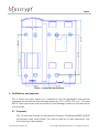
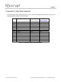
Bioscrypt Inc. Architect & Engineer Specification V-Smart™ Fingerprint Reader May 2, 2006 1. Introduction The intent of this document is to describe the specifications, operation, and physical attributes of the V-Smart fingerprint reader, Model Number V-SMART, A, manufactured by Bioscrypt, Inc. The device specifications, installation specifications, and connections are provided in detail for system architects and engineers designing access control and other systems utilizing the V-Smart reader. 2. Description The V-Smart reader shall provide a 1:1 fingerprint verification utilizing an embedded Gemplus MIFARE contactless smart card reader. The V-Smart shall prevent unauthorized access via loaned, lost or stolen smart cards by requiring that the SiteKey stored on the card matches that of the reader and that the fingerprint of the person seeking entry match the identity of the cardholder. 3. Mechanical Specifications 3.1. Dimensions The V-Smart reader shall measure 5.32” x 4.69” x 2.52” (135 x 119 x 64 mm) and shall arrive disassembled. The V-Smart shall be comprised of: A. A wall plate that mounts directly to the wall or a double-gang box mounted in the wall. B. A fingerprint verification module that mounts to the wall plate. C. A smart card interface module that mounts to the wall plate. A 1:1 scale diagram of this wall plate with dimensions is provided in Figure 1: V-Smart Wall Mounting Plate. 3.2. Material The V-Smart reader shall be made of Polylac PA-765A, a high flow grade, flame retardant material to a UL94 V-0 standard. This material shall be used for the case body and the wall mounting plate and shall be an ABS plastic. Document# 430-00137-03 © Copyright 2003-2006, Bioscrypt Inc. All rights reserved. Page 2 The “finger mask” that surrounds the fingerprint sensor itself shall be a carbon fiber conductive plastic. 3.3. Fingerprint Sensor The V-Smart reader shall incorporate the Authentec, Inc. sensor model AF-S2. The AF-S2 sensor shall be manufactured of silicon and shall be capacitivebased. The sensor surface area shall measure 24 x 24 x 3.5 mm. The sensor shall additionally incorporate Authentec’s TruePrint technology, which utilizes a patented radio frequency (RF) imaging technique that allows the sensor to generate an image of the shape of the live layer of skin that is buried beneath the surface of the finger. For more information on this imaging technology, please visit http://www.authentec.com. 3.4. Color The V-Smart case shall have a charcoal gray body (ABS Grey – Pantone 426C). Furthermore, the color used in the “bioscrypt” text shall be Pantone 423C. 3.5. Weight The assembled V-Smart shall weigh 15 ounces (packaged weight for shipping shall be 1.6 pounds). 3.6. Mounting The wall mounting plate shall be designed to mount to a double gang box (the wall plate will not line up with the holes in a electrical square box) using 4 #6-32 screws in the oval holes. The shape of the holes shall provide for some adjustment to ensure the wall plate is mounted level. The V-Smart may additionally be mounted onto a wall anchor, wood or sheet metal using #4 flat head screws (thread diameter of <0.125 inch and a head diameter of <0.250 inch) in the 4 outer holes. The access hole in the wall for wiring should be less than 4.5” wide so that the wall plate will cover it. It should also be less than 2.5” tall if mounting into a dry wall so that there is enough material to hold the anchor. The recommended size is 3.5” x 2.5”. Document# 430-00137-03 © Copyright 2003-2006, Bioscrypt Inc. All rights reserved. Page 3 The two V-Smart modules (fingerprint verification and smart card interface) must be connected behind the wall plate. Once the cables are connected, the wall plate may be mounted to the wall. The V-Smart modules shall have two tabs that slide into slots on the wall plate. Each module shall be secured to the wall plate by a single #4-40 inch screw. 3.7. Mounting Position The V-Smart should be mounted on the wall or structure to be in compliance with all American Disabilities Act (ADA), local and federal laws as they apply to the installation. The reader should also be mounted at a height that is comfortable to use. In general, the reader is mounted such that the height of the sensor (top of the device) is between 48 and 54 inches from the ground. Should the reader be installed below this mounting height (i.e. on a turnstile), installation of a wedge piece shall be required between the mounting surface and the V-Smart wall mounting plate. Please contact Bioscrypt Technical Support for further information. Furthermore, the reader will require free space above the reader such that the user has room to place their finger on the sensor. Roughly, 2-3 inches (or more) of free space is recommended depending on if there is any obstruction interfering with the view of the V-Smart. The reader should also be provided with free space (roughly 3-4 inches recommended) below the device for convenient access to the bottom RJ11 RS-232 port (see Section 7.3: RS-232 RJ11 Port for further details). If connecting an external card reader to the V-Smart for enrollment purposes, the two devices should be placed in close proximity to one another to make it simple for the enrollment administrator to first present the card at the external card reader and then prompt the user to place their finger on the sensor for enrollment. Please see Section 8.3: External Wiegand Reader for further information. Document# 430-00137-03 © Copyright 2003-2006, Bioscrypt Inc. All rights reserved. Page 4 Figure 1: V-Smart Wall Mounting Plate 4. Certifications and Approvals The V-Smart has been tested for compliance with all applicable international standards and shall have the following approvals: FCC, UL294, CSA, cUL, CE under R&TTE. These approvals shall be printed on the labeling located on the rear panel of the reader. 4.1. Frequency The V-Smart shall include an embedded Gemplus GemEasyLink680SL MIFARE contactless smart card reader. This device shall be a radio-transceiver with the following characteristics: Document# 430-00137-03 © Copyright 2003-2006, Bioscrypt Inc. All rights reserved. Page 5 Operating Frequency Range: RF Power Rating: RF Output Impedance: 13.553 – 13.567 MHz 0.0 Watts 50 Ohms 4.2. FCC Information to Users The V-Smart shall comply with the limits for a Class A digital device, pursuant to Part 15 of the FCC Rules. These limits are designed to provide reasonable protection against harmful interference when the equipment is operated in a commercial environment. This equipment generates, uses, and can radiate radio frequency energy and, if not installed and used in accordance with the instruction manual, may cause harmful interference to radio communications. Operation of this equipment in a residential area is likely to cause harmful interference in which case the user will be required to correct the interference at his own expense. 4.3. UL and cUL Information to Users The V-Smart shall comply with the Standard for Access Control System Units for UL294 and with CSA C22.2 No. 205 for the cUL Mark. 4.4. CE Information to Users The V-Smart shall have the CE mark, for compliance with CISPR22, EN 55022 and EN 50082-1 requirements. For European Union (EU) countries, the V-Smart shall be compliant with CE under the R&TTE Directive, related to the radio transceivers that are part of its design. The V-Smart shall be compliant with this directive if, and only if, the user installs the Bioscrypt specified R&TTE Installation Kit (Bioscrypt part number 832-00103-00). This filter kit shall be included with any V-Smart product if it was shipped to a country within the EU. The R&TTE Installation Kit shall consist of two filters: a line filter used to minimize conducted emissions from power supply lead lengths greater than 3 meters and a DB15 “Pass-Thru” filter used to minimize radiated emissions. Line Filter: Manufacturer: Part Number: Document# 430-00137-03 JMK Filters Amhearst, New Hampshire USA, 03031 http://www.JMKFilters.com FF-1586-1 © Copyright 2003-2006, Bioscrypt Inc. All rights reserved. Page 6 Pass-Thru Filter: Manufacturer: Spectrum Control Fairview, Pennsylvania USA, 16415 http://www.SpectrumControl.com 56-605-019 Part Number: NOTE: The installation of these filters is mandatory for the registered CE mark, and associated R&TTE directive compliance to be valid within the European Union. Failure to do so will render the CE mark and consequent right to operate the equipment null and void. Refer to the Veri-Series Installation Manual: Appendix C for information on proper installation of these filters. 4.5. European Certification Documentation The V-Smart reader shall contain radio transmitters. Hereby, Bioscrypt declares that the V-Smart shall be in compliance with the essential requirements and other relevant provisions of Directive 1999/5/EC. Restrictions of Use Bioscrypt has notified and gained approval to sell the V-Smart in the following EU countries. There shall be no restrictions of use for the V-Smart reader within these countries. Austria Belgium Denmark Finland France Germany Greece Ireland Italy Luxemburg Netherlands Portugal Spain Sweden United Kingdom Declarations of Conformity are listed on the following pages for: R&TTE Directive 1999/5/EC EMC Directive 89/336/EEC Low Voltage Safety Directive 73/23/EEC Document# 430-00137-03 © Copyright 2003-2006, Bioscrypt Inc. All rights reserved. Page 7 DECLARATION OF CONFORMITY FOR THE R&TTE DIRECTIVE 1999/5/EC Manufacturer’s Name/Address: Address: Contact Person: Equipment Type: Product Name: Model No.: RF Output Power: Transmitter Operating Frequency Range: Emission Designation: Duty Cycle: Year of manufacture: Country Of Manufacture: The above product has been tested by UltraTech Engineering Labs Inc., and found to comply with: Test Laboratories: Bioscrypt Inc. 5450 Explorer Drive, Suite 500 Mississauga, Ontario Canada, L4W 5M1 Mr. Shiraz Kapadia, Director of Manufacturing Phone #: 905-624-7719 Fax #: 905-624-7742 Email Address: [email protected] Radio Communications Equipment V-Smart V-Smart, A -19.3 dBuA/m 10 meters 13.553-13.567 MHz 3K0D1D 100% 2003 Canada European Telecommunications Standards Institute (ETSI) EN 300 330-1 V1.3.1 (2001-06) & EN 300 330-2 V1.1.1 (2001-06); Radio Equipment and Systems; Short Range Devices (SRD); Technical Characteristics and Test Methods for Radio Equipment in the Frequency Range 9 kHz to 25 MHz and Inductive Loop Systems in the Frequency Range 9 kHz to 30 MHz, Parts 1 and 2. UltraTech EMC Labs Inc. 3000 Bristol Circle Oakville, Ontario, Canada, L6H 6G4 I, the undersigned, hereby declare that the equipment as tested is representative within manufacturing tolerance to units Manufacturer Shiraz Kapadia Director of Manufacturing Mississauga, ON, Canada September 9, 2003 Document# 430-00137-03 Legal Representative in Europe Neil McDonald Director of Sales, EMEA High Wycombe, England November 25, 2002 © Copyright 2003-2006, Bioscrypt Inc. All rights reserved. Page 8 DECLARATION OF CONFORMITY FOR THE EMC DIRECTIVE 89/336/EEC Manufacturer’s Name/Address: Address: Contact Person: Equipment Type: Product Name: Model No.: RF Output Power: Transmitter Operating Frequency Range: Emission Designation: Duty Cycle: Year of manufacture: Country Of Manufacture: The above product has been tested by UltraTech Engineering Labs Inc., and found to comply with: Test Laboratories: Bioscrypt Inc. 5450 Explorer Drive, Suite 500 Mississauga, Ontario Canada, L4W 5M1 Mr. Shiraz Kapadia, Director of Manufacturing Phone #: 905-624-7719 Fax #: 905-624-7742 Email Address: [email protected] Radio Communications Equipment V-Smart V-Smart, A -19.3 dBuA/m 10 meters 13.553-13.567 MHz 3K0D1D 100% 2003 Canada European Telecommunications Standards Institute (ETSI) EN 301 489-1 V1.4.1 (2002-04) & EN 301 489-3 V1.4.1 (2002-08) – Electromagnetic Compatibility and Spectrum Matters (ERM); Electromagnetic Compatibility (EMC) Standard for Radio Equipment and Services, Parts 1 and 3. UltraTech EMC Labs Inc. 3000 Bristol Circle Oakville, Ontario, Canada, L6H 6G4 I, the undersigned, hereby declare that the equipment as tested is representative within manufacturing tolerance to units Manufacturer Shiraz Kapadia Director of Manufacturing Mississauga, ON, Canada September 9, 2003 Document# 430-00137-03 Legal Representative in Europe Neil McDonald Director of Sales, EMEA High Wycombe, England November 25, 2002 © Copyright 2003-2006, Bioscrypt Inc. All rights reserved. Page 9 DECLARATION OF CONFORMITY FOR THE LOW VOLTAGE SAFETY DIRECTIVE 73/23/EEC Manufacturer’s Name/Address: Address: Contact Person: Equipment Type: Product Name: Model No.: RF Output Power: Transmitter Operating Frequency Range: Emission Designation: Duty Cycle: Year of manufacture: Country Of Manufacture: The above product has been tested by UltraTech Engineering Labs Inc., and found to comply with: Test Laboratories: Bioscrypt Inc. 5450 Explorer Drive, Suite 500 Mississauga, Ontario Canada, L4W 5M1 Mr. Shiraz Kapadia, Director of Manufacturing Phone #: 905-624-7719 Fax #: 905-624-7742 Email Address: [email protected] Radio Communications Equipment V-Smart V-Smart, A -19.3 dBuA/m 10 meters 13.553-13.567 MHz 3K0D1D 100% 2003 Canada EN 60215:1996 +A1:1996 - Safety Requirements for Radio Transmitting Equipment UltraTech EMC Labs Inc. 3000 Bristol Circle Oakville, Ontario, Canada, L6H 6G4 I, the undersigned, hereby declare that the equipment as tested is representative within manufacturing tolerance to units Manufacturer Shiraz Kapadia Director of Manufacturing Mississauga, ON, Canada September 9, 2003 Document# 430-00137-03 Legal Representative in Europe Neil McDonald Director of Sales, EMEA High Wycombe, England November 25, 2002 © Copyright 2003-2006, Bioscrypt Inc. All rights reserved. Page 10 5. Environmental Specifications The V-Smart shall be manufactured for indoor use, and if placed outdoors must be installed within a complete Bioscrypt certified enclosure to protect the reader against direct contact with the elements, including rain, sun, snow, or excessive moisture. Failure to place V-Smart readers installed outdoors within such an enclosure will void the warranty. 5.1. Bioscrypt Enclosure The Bioscrypt certified enclosure shall be required for outdoor installations and shall optionally include a heater that shall trigger on when temperatures reach below 24° C (75° F). For further information on the Bioscrypt certified enclosure, including power requirements and schematics, please contact Bioscrypt Technical Support. 5.2. Temperature The electronics and mechanical parts that make up the V-Smart reader shall be rated to operate in a temperature range of 0° C to 60° C (32° F to 140° F). However, the extremes of this temperature range will not be a comfortable operating range for users of the system. The temperature range for the environment in which the reader will be installed should be limited to 10° C to 50° C (50° F to 120° F). Additionally, the reader should not be placed in direct sunlight or in uncontrolled environments (indoors or out). 5.3. Humidity The V-Smart reader shall be rated to operate within a humidity range of 0% to 95% non-condensing. 5.4. Vibration The environment in which the V-Smart shall be installed should not subject the reader to vibration. 6. Electrical Specifications 6.1. Pigtail Connections The V-Smart reader shall include a 15-pin DB15M connector for external connections to power and other devices. A 15-conductor color-coded pigtail Document# 430-00137-03 © Copyright 2003-2006, Bioscrypt Inc. All rights reserved. Page 11 cable shall be provided with each V-Smart reader to facilitate connecting the reader to other wiring. The remainder of this document assumes you are using the pigtail cable provided to make connections. Appendix A: Pigtail Cable Connections lists the connections available through the pigtail. Also, see Section 7: Communications and Section 8: Connections to External Equipment. For additional instructions on installing the V-Smart reader, please refer to the Veri-Series Installation Manual which shall be provided within the software CD received with the reader. 6.2. Power Requirements The V-Smart reader shall operate on DC power between 9 and 12 volts, however, operation at 12 VDC is recommended. The V-Smart shall consume approximately a maximum of 5 watts of power: At 12 VDC the device shall have an inrush current of 1 amp for 10mS and shall require continuous current up to 400 mA during operation. The V-Smart reader shall require an isolated power supply (not provided with reader). This power supply may be optionally purchased from Bioscrypt. The power supply should be: Isolated from other equipment including card reader power, lock power, Access Control System power and other interference-causing or non-Bioscrypt electro-mechanical devices (i.e., power supply should be dedicated to the V-Smart reader(s)). Regulated and filtered. Protected by means of an uninterruptible power supply (UPS) or battery backup. A UL-Listed Class II power supply at 12 VDC, 500 mA continuous. Additionally, the power supply should NOT be: Connected to any device that may put transients on the power supply line or cause the power supply to behave improperly. If transients are an issue in the installation, a transient voltage suppression device is also recommended. If power is to be distributed to various V-Smart readers over some distance, then it is important to take into consideration the resistance of the cable used for power distribution. Since the reader shall require significant power levels, the cable should be of appropriate gauge (18AWG or better is Document# 430-00137-03 © Copyright 2003-2006, Bioscrypt Inc. All rights reserved. Page 12 recommended). Pin 11 should be connected to Power GND and Pin 13 should be connected to +12 VDC power input. 6.3. Grounding The V-Smart reader shall have various grounding requirements: Power GND (Pin 11): the return for the input power supply. Pin 11 shall be connected to the negative on the power supply. Refer to Section 6.2: Power Requirements for further details. Wiegand GND (Pin 6): the reference ground for the Wiegand Data 0 and Data 1 interface. Pin 6 shall be connected to the GND on reader port of the Access Control System. Refer to Section 8.3: External Wiegand Reader and Section 8.4: Access Control System for further details. Signal GND (Pin 12): the reference for serial communications. Pin 12 shall be connected to the GND on the serial port or RS-485/RS-232 converter (dependent on communications protocol selected). Refer to Section 7: Communications for further details. Safety GND (Pin 15): protects the V-Smart (sensor and internal electronics) from electro-static discharge (ESD) by providing a safe discharge path to an earth ground. Refer to Section 8.2: Earth Ground and Section 9.6: Fingerprint Placement: Lock, Drop & Hold for further details. 7. Communications The V-Smart shall include support for RS-232 and RS-485 serial communications. This is primarily intended for use with a PC running the VeriAdmin software, which allows for template management (enrollments, deletions, editions, distribution) and reader configuration. If RS-232 and RS-485 communications are desired for use with an application other than the VeriAdmin software, the BIO-SDK (Bioscrypt Software Development Kit) shall be required to integrate V-Smart support into a custom application. Refer to Section 11: VeriAdmin Management Software for further details on the software features. The V-Smart shall provide three serial communications ports: RS-485 accessible through the pigtail (DB15) RS-232 accessible through the pigtail (DB15) RS-232 accessible through the bottom RJ11 port Document# 430-00137-03 © Copyright 2003-2006, Bioscrypt Inc. All rights reserved. Page 13 Only two of the three ports may be activated at a time. By default, the V-Smart shall be configured for Port Mode 0 (Host RS-232 DB15 / Aux RS-232 RJ11) because Host RS-232 protocol is necessary for communications between the smart card interface and fingerprint verification modules. Thus, the RS-232 DB15 port may NOT be used for PC communications. Typically, V-Smart readers do not require RS-485 communication since the fingerprint templates are stored on the smart card itself rather than in the reader’s memory; thus, they do not require a network for template distribution. Should you desire to implement a RS-485 network of V-Smart readers, MV1200 Veri-Series Port Mode 2 must be chosen which activates both RS485 and RS-232 Host communication, leaving the bottom RJ11 RS-232 port disabled. 7.1. RS-485 DB15 Port The V-Smart reader shall support RS-485 serial communications protocol accessible from the DB15 port. The V-Smart shall require configuration by means of an active port (RS-232 RJ11 since RS-232 DB15 is dedicated to connection to smart card interface module) to activate the RS-485 DB15 port. To activate the RS-485 DB15 port, a Port Mode of 2 (Host RS-232 DB15 / Aux RS485 DB15) must be selected. Note that if Port Mode 2 is selected, the bottom RJ11 RS-232 port will be de-activated. For RS-485 protocol support, an external converter must be utilized. Bioscrypt has tested and qualified the B&B Electronics 485TBLED RS-485/RS-232 converter for use with the V-Smart reader (must be purchased separately). The B&B Electronics converter connects directly to both the Host PC and to the V-Smart reader. This converter shall support “sense data,” also referred to as “send data”. This is necessary since the V-Smart reader shall utilize a halfduplex (2-wire) RS-485 signal with no RTS/CTS control on the RS-232 line. The RS-485 communications protocol should be chosen if a network of more than one V-Smart reader is being installed or if a single reader is being installed more than 150 feet from the PC or other host. This network is optional and shall not be required for template distribution since the fingerprint templates are stored on the smart card and not the reader’s internal memory. The maximum cable distance for a RS-485 network is 4,000 feet (1200 meters), over which no more than 31 V-Smart readers can be added. To extend these limitations, contact Bioscrypt Technical Support. No end-of-line termination is required at a baud rate of 9600. For RS-485 communications, the V-Smart readers must be connected as follows: Document# 430-00137-03 © Copyright 2003-2006, Bioscrypt Inc. All rights reserved. Page 14 Use Category 5 rated cable (shielded is recommended). This cable should be dedicated to the RS-485 network connection between the B&B Electronics 485TBLED converter and the V-Smart readers and should not be used for any other purpose. Use Pin 7 [RS-485 (-)], Pin 8 [RS-485 (+)] and Pin 12 [Signal GND]. The B&B Electronics 485TBLED converter shall require 12VDC/100mA power from an external supply. Connect the B&B Electronics 485TBLED converter to the PC’s DB9 COM Port using a DB25-to-DB9 cable. Connect the V-Smart readers in a daisy-chain configuration (i.e. Converter → Reader 1 → Reader 2 → Reader 3, etc.). Do NOT use a star or other multi-drop configurations. For a wiring diagram and more specific instructions please refer to the Configuration for Veri-Series Fingerprint Readers and RS-485/RS-232 Converter application note. 7.2. RS-232 DB15 Port The RS-232 DB15 port shall be dedicated to communications between the fingerprint verification module and smart card interface module of the VSmart and therefore, shall not be available for PC communications. 7.3. RS-232 RJ11 Port The V-Smart reader shall provide a RS-232 RJ11 port on the bottom of the device for convenient access. This shall be the default configuration for the reader. This RJ11 port is implemented as a 6p6c (6-position, 6-conductor) jack. This port is physically protected by means of a pin-in-hex security screw. Additional security is provided through a password protection feature, which may be activated through the VeriAdmin software. Additionally, an RJ11-to-DB9 programming cable shall be provided with each V-Smart reader. This cable is a 6-foot, 6p6c straight-thru cable with an RJ11to-DB9 adaptor. This cable should be used to configure the reader and may optionally be used for template management and other functions desired via a local connection. The RS-232 protocol does not run on a differential pair of wires like the RS-485 protocol, and shall therefore be less immune to EMI and other noise sources. The tradeoff for RS-232 shall be speed versus distance. RS-232 communications distances are dependent on the baud rate (bps). For Document# 430-00137-03 © Copyright 2003-2006, Bioscrypt Inc. All rights reserved. Page 15 example, at 9600 baud, a distance of 150 feet is possible using shielded cable, but at 57600 baud, a maximum of 20 feet is recommended. By default, this port will be configured for 57600 baud. To create your own RJ11-to-DB9 cable the following is required: Use Category 5 rated cable (shielded is recommended). This cable should be dedicated to the RS-232 connection between the V-Smart reader and the PC or host device. Use a female DB9 connector. Use a 6p6c RJ11 jack. Orient the jack so that the 6 gold pins are facing upward and the jack (or clip) is facing the user. Pin 1 would be on the far left and Pin 6 would be on the far right. Connect the RJ11 Pin 1 (RS-232 Tx) to the DB9 Pin 2. Connect the RJ11 Pin 2 (RS-232 Rx) to the DB9 Pin 3. Connect the RJ11 Pin 5 (Signal GND) to the DB9 Pin 5. 8. Connections to External Equipment 8.1. Power The V-Smart reader shall require an isolated power supply (not provided with reader). This power supply may be optionally purchased from Bioscrypt. Two conductors shall be required for this connection (Pins 11 & 13). Since the reader requires significant power levels (see Section 6.2: Power Requirements), the cable should be of appropriate gauge (18 AWG or better is recommended). 8.2. Earth Ground The V-Smart reader shall require a homerun connection to Earth Ground using Pin 15. This connection shall help to protect the V-Smart (sensor and internal electronics) from electro-static discharge (ESD) by providing a safe discharge path to an earth ground. Pin 15 must be connected to a proper earth ground such as a cold-water copper pipe or building ground. The connection chosen for Earth Ground should measure less than 4 ohms resistance when measured against a known local Earth Ground. DO NOT CONNECT PIN 15 TO POWER GROUND. At a minimum, this connection should be made with a lowresistance, single-conductor cable (14 – 18 AWG is recommended). Internally, Pin 15 is connected to the finger mask (conductive plastic surrounding the fingerprint sensor) and should be used in conjunction with the Ridge-Lock. Document# 430-00137-03 © Copyright 2003-2006, Bioscrypt Inc. All rights reserved. Page 16 Refer to Section 9.6: Fingerprint Placement: Lock, Drop & Hold for further details. If no such connection is provided, Bioscrypt will consider that the reader was not properly installed and may consider the warranty void. 8.3. External Wiegand Reader The V-Smart reader shall include an embedded Gemplus MIFARE contactless smart card reader. The V-Smart shall NOT have the ability to read proximity Wiegand sequences directly. The V-Smart by default shall generate a Wiegand output sequence based on the fingerprint template ID number. If using dual-technology contactless smart cards (such as HID 1431 Smart + Prox cards), the designated V-Smart enrollment station may optionally capture the Wiegand sequence as provided by the proximity portion of the card by means of an external proximity card reader. Once captured, the sequence may be written to the smart card along with the enrolled fingerprint template where the two items are linked together. When the dual-technology cards are used in this fashion, V-Smart readers used for access control shall simply send the Wiegand sequence from the smart card to the Access Control System. In this case, the Wiegand output sent by V-Smart shall be identical to the Wiegand output sent by the proximity card reader when the same card is presented to both devices. Any V-Smart readers used for access control shall NOT require the connection to the external card reader. To enroll cards in this manner, a direct connection shall be required from the proximity card reader to the Wiegand input lines of the V-Smart reader that has been designated as the enrollment station using the following three conductors: Wiegand In Data 0 (Pin 2) connected to the card reader Data 0 Wiegand In Data 1 (Pin 4) connected to the card reader Data 1 Wiegand GND (Pin 6) connected to the card reader Power GND* An 18 – 22 AWG cable should be used for this connection. The V-Smart reader by default shall have the Wiegand input activated for Standard 26-bit Wiegand format. The reader shall support other formats. Refer to Appendix B: Wiegand Protocol for further information. *Wiegand GND (Pin 6) should be commoned to both Power GND on the external Wiegand reader and the Access Control System reader Power GND if Wiegand output is also used (refer to Section 8.4: Access Control System). Document# 430-00137-03 © Copyright 2003-2006, Bioscrypt Inc. All rights reserved. Page 17 Pin 6 acts as the reference ground for the Wiegand Data 0 and Data 1 interface. 8.4. Access Control System The V-Smart reader shall support Wiegand protocol output for connection to an Access Control System (ACS). This system may provide advanced access control features such as audit trails, user-defined access scheduling, antipassback, etc. The V-Smart by default shall generate a Wiegand output sequence based on the fingerprint template ID number, unless a Wiegand sequence has been provided to the V-Smart reader during enrollment and stored on the smart card. Please refer to Section 8.3: External Wiegand Reader for further details. An 18 – 22 AWG cable should be used for this connection. At 18 AWG, a distance of 500 feet is possible. For Wiegand output the V-Smart reader shall require a homerun connection to the ACS using the following three conductors: Wiegand Out Data 0 (Pin 1) connected to the ACS Data 0 Wiegand Out Data 1 (Pin 3) connected to the ACS Data 1 Wiegand GND (Pin 6) connected to the ACS reader power GND (0 VDC)** The V-Smart reader shall by default have the Wiegand output activated for Standard 26-bit Wiegand format. The reader shall support other formats. Refer to Appendix B: Wiegand Protocol for further information. **Wiegand GND (Pin 6) should be commoned to both Power GND on the external Wiegand reader and Access Control System reader Power GND. Pin 6 acts as the reference ground for the Wiegand Data 0 and Data 1 interface. 8.5. Line Trigger The V-Smart reader shall include a Line Trigger, a low-level signal that is triggered following a successful verification. By default, this line shall be inactive and must manually be activated through use of the VeriAdmin management software provided with the reader. When the Line Trigger is activated, the user must also specify the duration (in seconds) the trigger should be set high. This source output is an open-drain drive capable of 50 Document# 430-00137-03 © Copyright 2003-2006, Bioscrypt Inc. All rights reserved. Page 18 mA with a maximum voltage drop of 1 VDC from a 5 VDC source. This drop is load-dependent. 8.6. PC or other Host Device The V-Smart reader shall support RS-232 and RS-485 serial communications protocols for connection to a PC or other host device. Each V-Smart reader shall include a VeriAdmin software CD. This software allows for reader configuration and template management. For more information on the VeriAdmin software functionality please refer to Section 11: VeriAdmin Management Software. If connecting to a PC, it should have the following characteristics: Operating System: Windows 98, ME, NT4.0, 2000, or XP (not compatible with Windows 95) 486-compatible 16 MB RAM 30 MB Disk space DB9 Serial communications port (do not support USB ports) For more information on the RS-232 and RS-485 connections please refer to Section 7: Communications. Although the V-Smart reader does not have built-in Ethernet support, it may be connected to a Lantronix UDS-10 Serial Device Server for this purpose. For more information on this connection please refer to the application note Configuration for Veri-Series Fingerprint Readers and Lantronix UDS-10 Serial Device Server. 9. Operation The V-Smart reader shall be designed to integrate easily into most access control systems. To function, a fingerprint must be enrolled and stored on a MIFARE contactless smart card and this can be done through the VeriAdmin software included with the reader. Once a fingerprint is enrolled, authentication may be performed any number of times. After authentication, the V-Smart shall send a Wiegand string to the Access Control System or other host equipment for appropriate action. 9.1. Fingerprint Template Capacity Document# 430-00137-03 © Copyright 2003-2006, Bioscrypt Inc. All rights reserved. Page 19 The V-Smart shall support an unlimited number of users since the fingerprint template file is stored on the smart card itself rather than on the V-Smart reader’s internal memory. A maximum of two fingerprint templates may be stored per contactless smart card. 9.2. Supported Cards The V-Smart shall support the following MIFARE contactless smart cards: Gemplus GemEasy 8000 (1 kByte memory) HID Corp. HID 1430* (1 kByte memory) HID Corp. HID 1431** (1 kByte memory) IDentiSMART Series by IDenticard (1 kByte memory) The V-Smart reader may also support other cards. Please contact Bioscrypt Technical Support to confirm card compatibility. *Order HID cards non-programmed. **Order HID cards programmed only for 125 kHz or entirely non-programmed. 9.3. Memory The V-Smart reader shall utilize non-volatile flash memory to store all data configurations and shall therefore not lose any configuration information if the reader is powered down. 9.4. SiteKey The SiteKey shall be a password used by the V-Smart, the smart cards, and the VeriAdmin software to communicate and transfer information. If the SiteKey stored in the V-Smart does not match the SiteKey stored in the smart card, the V-Smart will be unable to read or write to the card. This key shall ensure that only authorized smart cards are used at a specific installation. Additionally, the SiteKey shall act as the administrator password so that only authorized personnel may perform read/write functions on the V-Smart, such as enrollments, deletions, and V-Smart security configuration. By default, each V-Smart reader shall contain an empty-string for the SiteKey that should be configured prior to enrollment. Each installation must set their own SiteKey to distinguish their V-Smart contactless smart cards from every other V-Smart installation. The SiteKey shall be stored within the internal memory of the V-Smart and shall be encrypted and stored on the smart card Document# 430-00137-03 © Copyright 2003-2006, Bioscrypt Inc. All rights reserved. Page 20 itself. For security purposes, the SiteKey shall not be stored within the VeriAdmin software or PC, and may NOT be retrieved by the V-Smart. For more information on the SiteKey, please refer to the Veri-Series Operations Manual: Appendix E- V-Smart Administrator SiteKey Management. 9.5. User Interface The V-Smart shall have a common user interface. A green LED on the front of the reader shall indicate that power is on. A bi-color LED on the top of the reader shall display green, red, or amber (green and red together). The top LED may display in an off, solid or blinking (flashing) state. The color and state of the top LED may also be customized through the use of the VeriAdmin software. By default, the color and state of the top LED shall have particular meanings as shown in Table 1: V-Smart LED Feedback. Top LED Indicator Off Solid Red Solid Amber Solid Green Flashing Red Meaning Reader is Idle No Templates Stored on Smart Card Biometric Authentication Failed Place Finger on Sensor Biometric Authentication Accepted Enrollment Fingerprint Image Captured SiteKey Invalid* Table 1: V-Smart LED Feedback *If the V-Smart top LED returns a flashing red state after presenting a smart card to the reader, this indicates that the V-Smart was unable to read the card due to an invalid SiteKey between the V-Smart and the smart card. For more information on the SiteKey refer to Section 9.4: SiteKey. 9.6. Fingerprint Placement: Lock, Drop & Hold A Ridge-Lock shall be provided as part of the fingerprint sensor mask as a fingerprint placement guide and a means to discharge ESD. To properly place the finger on the sensor, the user should slide their finger across this Ridge-Lock, parallel to the sensor. Once the Ridge-Lock locks into place under the first joint, the user should then lower the finger evenly onto the sensor and apply moderate pressure. The user should hold the finger on the sensor until the top LED turns off and returns a green LED. A Macromedia Flash animation depicting proper fingerprint placement using the Ridge-Lock may Document# 430-00137-03 © Copyright 2003-2006, Bioscrypt Inc. All rights reserved. Page 21 be viewed online at http://www.bioscrypt.com > Support > Enrollment Tips. This information is also available for download as a PDF file. The Ridge-Lock is designed as a guide to help the user to properly and consistently position their finger on the sensor so as to fully capture the fingerprint core, the unique information-rich area of the fingerprint. When used properly during enrollment and authentication, the Ridge-Lock shall help to reduce false rejections. As the end user’s first point of contact with the reader, the Ridge-Lock is also designed as means of discharging ESD through the Earth Ground connection, which is manufactured using a carbon fiber conductive plastic. This shall help to protect the sensor from damage by ESD. This requires that the reader have a proper connection to Earth Ground. For more information on this connection please refer to Section 6.3: Grounding and Section 8.2: Earth Ground. 9.7. Enrollment Enrollment is the process of adding users to the fingerprint reader system. The V-Smart shall incorporate a one-touch enrollment process. Enrollment shall be initiated at a PC running the VeriAdmin software and may not be performed directly at the reader without the use of the software. The Enrollment PC should be located in close proximity to a V-Smart reader. When initiated, the template that is created through the enrollment process may be stored either on the PC or the smart card itself. When saved to the PC, the fingerprint template shall not be usable on the V-Smart reader for authentication until the template is transferred to the smart card. When enrollment is initiated, the reader shall display a solid amber LED to indicate to the user to place a finger on the sensor. When the fingerprint is captured, the LED shall turn off. Once the processing is completed, the LED shall turn red or green depending on the result. The reader shall also produce an audible tone when enrollment is successful. The software shall provide feedback regarding the image capture which allows the enrollment administrator to validate that the fingerprint core was fully captured and properly centered in the field of view. Additionally, quality and content scores shall be returned rating the enrollment; however, the image capture should act as the ultimate deciding factor in accepting the enrollment. This typically tends to yield a higher quality database of fingerprint templates, helping to reduce false rejections. Document# 430-00137-03 © Copyright 2003-2006, Bioscrypt Inc. All rights reserved. Page 22 A Wiegand sequence may optionally be written to the smart card at the time of enrollment. This sequence shall be linked to the fingerprint template and shall be released to the access control panel upon successful authentication. This sequence is not required as the V-Smart may generate a Wiegand output based on the template ID number. For more information, please refer to Section 8.3: External Wiegand Reader. When a template is stored on the smart card after enrollment is complete, the template shall reside on the smart card until deleted, and the user shall be able to authenticate on this particular reader as long as the template is resident on the card and the SiteKey is identical between the V-Smart and the smart card. For more information, refer to Section 9.4: SiteKey. During the enrollment process, the V-Smart reader shall not be available for access control functions. This, however, shall not affect other readers on the network (if a network is in place). In many circumstances, it is recommended that an additional reader be designated for use as an Enrollment Station. 9.8. Fingerprint Template Format During the enrollment process, the V-Smart shall create a fingerprint template roughly 348 bytes and shall be compatible with other Bioscrypt authentication devices (i.e. V-Flex, V-Prox, V-Smart iCLASS, V-Station, VStation Prox, V-Station MIFARE, V-Station iCLASS). This template is smaller in size than identification templates and may not be converted to identification templates for use on a searching device (i.e., V-Pass or V-Station Search). 9.9. Template Distribution The V-Smart shall utilize a portable database - the fingerprint templates are stored on the smart card itself rather than on the V-Smart reader’s internal memory. Thus, template distribution shall not be necessary. 9.10. Authentication Authentication is the process of providing the V-Smart with a valid smart card to download a previously enrolled fingerprint template, presenting a candidate fingerprint to the sensor, and getting a result of pass, fail, or invalid ID. The V-Smart reader shall be based on a digital signal processor (DSP) that utilizes a fingerprint sensor to capture an image of the presented finger. The authentication process on the V-Smart is as follows: Document# 430-00137-03 © Copyright 2003-2006, Bioscrypt Inc. All rights reserved. Page 23 The user presents the smart card to the belly of the smart card interface module of the V-Smart reader The V-Smart shall return an amber LED to indicate that the SiteKey, template data and optional Wiegand string were successfully passed from the smart card to the reader and stored in a buffer. If the data was not successfully passed, or an invalid SiteKey was stored on the card, the V-Smart shall instead return a flashing red LED to indicate failure. The user will present their finger to the sensor The V-Smart sensor shall capture the fingerprint The V-Smart DSP shall perform a 1:1 verification between the captured image and the stored template The V-Smart shall return a red or green LED indicating failure or pass. On a pass, the V-Smart shall perform one of the following actions: o Generate and release a Wiegand sequence to the Access Control System based on the template ID number and a pre-configured site code (the default action) o Release the Wiegand sequence from buffer to an Access Control System (if a Wiegand sequence was provided and stored during the enrollment process). o Activate the Line Trigger (depending on the reader’s configuration). Due to the nature of the 1:1 (one-to-one) algorithm utilized by the V-Smart, the smart card input shall be required in order to initiate the biometric authentication. 9.11. Granting Access When used in conjunction with an Access Control System (ACS), physical access shall not be granted by the V-Smart directly. The V-Smart reader shall simply send a Wiegand data signal to the ACS. That system is responsible for logging and making the decision to release door locks, etc. When the Line Trigger feature is used, any user fingerprint template stored on a valid smart card shall have the ability to perform a biometric authentication and access the V-Smart reader. The V-Smart reader itself does not support advanced access control features (such as audit trails, user-defined access scheduling, anti-passback, request to exit buttons, etc.). For these features, an ACS shall be required. Document# 430-00137-03 © Copyright 2003-2006, Bioscrypt Inc. All rights reserved. Page 24 9.12. Biometric Authentication By default, the V-Smart reader shall require that users present a candidate fingerprint for authentication. However, biometric authentication may be globally disabled on the V-Smart reader. In this mode, the reader will act simply as a card reader and output a Wiegand string after a valid card has been presented. 10. Estimated Performance Bioscrypt works to continuously improve the performance of the core fingerprint authentication technology while also improving the usability and flexibility of the system. We have developed a database of real-world fingerprint images and use these images to test the algorithm used by the V-Smart. This database has increased in size to the point where today we perform 1,000,000 comparisons to generate the following statistics. 10.1. Performance Terminology Biometric systems typically state performance in terms of False Rejection Rates (FRR) and False Acceptance Rates (FAR). The FRR is the expected rate at which the system would incorrectly reject (fail) the correct fingerprint – this assumes that the ID number is provided correctly from a valid proximity card. The FAR is the expected rate at which the system would incorrectly accept (pass) the wrong fingerprint. 10.2. Authentication Algorithm The authentication algorithm allows for two different performance-tuning parameters: Global Security Threshold and individual Template Security Threshold. Table 2: Security Threshold Error Rates lists the FRR and FAR values for various security levels. The V-Smart will use the lower of either the Global Security or individual Template Security Threshold when performing the authentication. Security Threshold Very High (1) High (2) Medium (3) Document# 430-00137-03 FRR 1/100 1/200 1/1000 FAR 1/20,000 1/5000 1/1000 © Copyright 2003-2006, Bioscrypt Inc. All rights reserved. Page 25 Low (4) Very Low (5) None (0)* Password Only (6)** 1/5000 1/10,000 0 0 1/200 1/100 1 1 Table 2: Security Threshold Error Rates The V-Smart by default shall be configured to a Medium Global and Template Security Threshold. This threshold level is referred to as the Equal Error Rate (EER) or the point at which the FRR is equal to the FAR. As shown above, the EER for the V-Smart is 1/1000. *The None Template Security Threshold level shall be applicable only to individual fingerprint template files and may not be applied as a global reader setting. When a level of None is selected for an individual fingerprint template, the reader shall not initiate a biometric authentication and shall instead accept any user that presents a card corresponding to a validly enrolled fingerprint template. There shall be two options for this setting: a finger is required, but any finger shall be accepted (the default setting), or no finger shall be required. **The Password Only Template Security Threshold is not applicable on a VSmart reader and is instead intended for a V-Station reader. Note that the VSmart shall not require a finger to be presented for biometric authentication for any fingerprint templates with a Template Security Threshold level of Password Only. For more information on this setting please contact Technical Support. 11. VeriAdmin Management Software Each V-Smart reader shall include a CD-ROM containing the VeriAdmin PC software. The VeriAdmin software supports Windows 98/NT4.0/ME/2000/XP. It is not tested under other Windows-compatible or non-Windows-based operating systems. The VeriAdmin Management Software may be used to perform the following functions: Secure smart cards with a SiteKey. Configure V-Smart smart card reader security settings Read/Write the fingerprint template information to a smart card Enroll new user fingerprint templates Edit existing user fingerprint templates Document# 430-00137-03 © Copyright 2003-2006, Bioscrypt Inc. All rights reserved. Page 26 Delete user fingerprint templates Adjust the parameters (communications, biometrics, Wiegand, line trigger, etc.) of a reader Configure the operation of the V-Smart top LED Manage a network of V-Smart readers (if one was installed) Perform firmware updates For further details on the VeriAdmin software and its operation, please refer to the Veri-Series Operations Manual (installed on the PC at the time of software installation). Document# 430-00137-03 © Copyright 2003-2006, Bioscrypt Inc. All rights reserved. Page 27 12. Appendix A – Pigtail Cable Connections The following table represents the color codes and signal descriptions used in the pigtail cable for the V-Smart reader. Pin # 1 2 3 4 5 6 7 8 9 10 11 12 13 14 15 Signal Description Original Cable (Gray Jacket) New Cable (Blue Jacket) Wiegand Out Data 0 Wiegand In Data 0 Wiegand Out Data 1 Wiegand In Data 1 Line Trigger Wiegand GND RS-485 (-) RS-485 (+) RS-232 TX RS-232 Rx Power GND Signal GND Power Input (9-12 VDC) Reserved Safety GND Red/Black Green/Black Orange Orange/Black Green Red Blue/Black White Black/White Red/White Black Green/White Blue/White Blue White/Black Green Green/White White White/Black Gray Black/White Blue/Black Blue Violet Violet/White Black Black/Red Red Red/White Green/Yellow Table 3: 15-Conductor Pigtail Cable Connections Document# 430-00137-03 © Copyright 2003-2006, Bioscrypt Inc. All rights reserved. Page 28 13. Appendix B – Wiegand Protocol The Wiegand protocol has become a standard means of communicating user identification numbers between access control front-end products, such as a card reader or keypad, and the access control system interface to that front-end. Some manufacturers have modified the original standard format for their own use, but often still support the original standard. The V-Smart reader shall support a variety of formats; however, the factory default is the Standard 26-bit format as described below. Note that the format selected shall be used for both Wiegand input (extracting sequence from external proximity card reader) and Wiegand output (releasing sequence to Access Control System). The V-Smart shall not support the use of a different format for input than output. 13.1. Standard 26-bit Format The Wiegand protocol is described completely in a document available from the Security Industry Association (SIA) as Access Control 26-bit Wiegand Reader Interface Standard. Without going into the detail provided in that document, the Wiegand communication format can be summarized as providing a series of binary bits (0 or 1) that are interpreted as two (2) data fields: site code and identification number. Proprietary and customized formats are prevalent and can contain extended data ranges or additional data fields, but the standard format is 26-bit. The 26-bit format is generally diagrammed as follows: 0 1 2 3 4 5 6 7 8 9 10 11 12 13 14 15 16 17 18 19 20 21 22 23 24 25 PE S S S S S S S S N N N N N N N N N N N N N N N N PO E E E E E E E E E E E E O O O O O O O O O O O O Where P represents a parity bit, S represents a bit from the Site Code (also referred to as a Facility Code), N is a bit from the ID Number (also referred to as Card ID), E represents bit positions that are used for Even parity calculations, and O represents bit positions that are used for Odd parity calculations. The facility code is 8 bits and supports values from 000 to 255. The ID number is 16 bits and supports values from 00000 to 65535. In the case of a V-Smart the ID number assigned to each fingerprint template should be enrolled in the Access Control System as the Card ID. Document# 430-00137-03 © Copyright 2003-2006, Bioscrypt Inc. All rights reserved. Page 29 13.2. Other Supported Formats The V-Smart shall support the following Pre-Defined Wiegand formats: Standard 26-bit Apollo 44-bit Northern 34-bit Northern 34-bit (no parity) Andover 37-bit* Generic 64-bit* Ademco 34-bit HID Corporate 1000 35-bit HID 37-bit Wiegand 4002 40-bit* Generic 34-bit* If the Access Control System is configured for a Wiegand format other than the default of Standard 26-bit, then the software shall be required to select the supported format. Only one format may be selected and configured into the reader at a time (i.e. the V-Smart reader shall not support both Standard 26-bit and Northern 34-bit output at the same time depending on the card or user). *This format is available as a Custom Pre-Defined Format and must be manually uploaded to the reader. Please refer to section 13.3: Custom PreDefined Formats. Contact Bioscrypt Technical Support to confirm compatibility with your reader. 13.3. Custom Pre-Defined Formats The V-Smart reader shall support the use of a Custom Wiegand Format. A slot on the Pre-Defined Wiegand Formats drop-down list shall be allocated to a Custom Wiegand Format. A Custom Wiegand Format file shall be required and must be uploaded onto the V-Smart reader. This file may be created only by the Bioscrypt Engineering Department after thorough tests are completed involving all necessary equipment (i.e. cards, Access Control System, etc.) to be utilized at the site. Please contact Bioscrypt Technical Support to see if the Wiegand format used by your Access Control System is available as a custom Wiegand format. 13.4. Pass-Thru Formats If the format you prefer to use is not available as a Pre-defined or Custom format, the V-Smart reader shall support a Pass-Thru mode. In this mode, critical information about the format is provided to the V-Smart reader, which shall allow the V-Smart reader to correctly generate the card ID required to Document# 430-00137-03 © Copyright 2003-2006, Bioscrypt Inc. All rights reserved. Page 30 send to the Access Control System. To support your proprietary Wiegand format in a Pass-Thru mode, the following is required: Wiegand data is interpreted as a standard binary representation (i.e. hex and other data interpretations are not supported) A contiguous series of bits for the ID number The sequence must be non-encrypted The Total number of bits in the format is 64 or fewer The bit stream provides the bits in order from Most Significant Bit (MSB) to Least Significant Bit (LSB) The V-Smart reader shall be unable to correctly generate the Card ID required by the Access Control System if the conditions above are not met. If your Wiegand format meets these requirements, then the following information is required to configure this format into the V-Smart reader in PassThru mode: Total Number of Bits in the format Start bit position of the ID number data in the format (note: Bioscrypt considers the first bit position as 0) Length of the ID number data in the format (number of card id bits) 13.5. Pre-Defined vs. Pass-Thru Functionality Advanced Wiegand functionality shall be available for use on a V-Smart when a Pre-Defined or Custom format is used that shall not be available for Pass-Thru formats. Since Bioscrypt has intimate knowledge of Pre-defined and Custom formats (including site code start and length, parity bit start and length, parity bit calculation, etc.), the following features are available for Pre-Defined and Custom formats: Alt Site Code: an alternate site code may be activated and selected. This code shall act as the site or facility code required by the Access Control System for access for successful authentications. When this option is not selected, the V-Smart shall generate and send a site code of 0. If a Wiegand sequence was provided and stored on the smart card during the enrollment process, the Alt Site Code field should not be selected so that the reader may instead pass through the site code as provided by the Wiegand sequence. Fail ID Code: a failure code may be activated and selected. This code shall supersede the ID portion of the Wiegand string for all failed authentications that occur at the reader. When this option is not Document# 430-00137-03 © Copyright 2003-2006, Bioscrypt Inc. All rights reserved. Page 31 selected, a Wiegand sequence shall not be sent to the Access Control System on biometric failures. Fail Site Code: a failure code may be activated and selected. This code shall supersede the site or facility code portion of the Wiegand string for all failed authentications that occur at the reader. When this option is not selected, a Wiegand sequence shall not be sent to the Access Control System on biometric failures. On Fail Send Inverse Parity: when activated, a failed authentication shall result in the Wiegand sequence being sent to the Access Control System with the parity bits inversed to indicate failure. This option should not be selected unless the Access Control System performs parity bit calculation and supports this feature. 13.6. Extended ID The V-Smart reader shall support Wiegand formats, which allocate up to 64 bits for the Card ID. Because Bioscrypt fingerprint templates by default use only up to a 32-bit ID, any Wiegand Formats which allocate more than 32 bits to the ID number shall require the V-Smart to be in a special Extended ID mode, which adds an Extended ID field to the fingerprint template. This field actually uses the Employee ID field (not shown in VeriAdmin) and the Password field (not available on a V-Smart). For Extended ID support, the V-Smart shall require firmware version 7.30 or greater with a VeriAdmin software version of 5.30 or greater. Also, a Custom Wiegand Format file or Pass-Thru Format shall be required to support Extended IDs. For more information on this feature, please contact Bioscrypt Technical Support. 13.7. Duress Signals The V-Smart reader shall support a Duress Finger Mode which offers users a way to indicate a duress situation (such as being forced to open a door) by authenticating with a specially designated “duress finger”. An individual fingerprint template may be specified as such by selecting the “Make Duress Finger” option during enrollment. One smart card may be used for both duress and non-duress finger templates. When a successful authentication occurs with such a template, the reader shall send the Wiegand sequence to the access control panel in reverse bit order. The Access Control System can then respond with the appropriate action (alerting security personnel, sounding alarms, etc.). To fully support this feature, the access control panel must also support reverse-bit Wiegand sequence duress signals. Document# 430-00137-03 © Copyright 2003-2006, Bioscrypt Inc. All rights reserved. Page 32 Technical Support Contact Information: Bioscrypt 2101 Rosecrans Ave., Suite 1250 El Segundo, CA 90245 USA Hours: 530A – 500P Direct: 310-760-4130 Toll-Free: 866-304-7180 Fax: 310-760-4137 E-mail: [email protected] Web: http://www.bioscrypt.com Disclaimer The information in this document has been carefully checked for accuracy and is presumed to be reliable. Bioscrypt, Inc. and its writers assume no responsibility for inaccuracies and reserve the right to modify and revise this document without notice. It is always our goal at Bioscrypt, Inc. to supply accurate and reliable documentation. If you discover a discrepancy in this document, please e-mail your comments to [email protected] or contact Bioscrypt Technical Support at the telephone numbers listed above. Bioscrypt accepts no liability for the misuse of third-party hardware mentioned in this document. In no case shall Bioscrypt be liable for damage to a reader resulting from the misuse of such hardware. Version Number: 4 Date: May 2, 2006 Corporate & Canadian Office 505 Cochrane Dr. Markham, ON L3R 8E3 T 905 940 7750 F 905 940 7642 www.bioscrypt.com Document# 430-00137-03 U.S. Office 2101 Rosecrans Ave., Suite 1250 Van Nuys, CA 91411 T 310 760 4101 F 310 227 8038 U.K. Office 35 Jackson Court, Hazlemere High Wycombe, Buckinghamshire England HP15 7TZ T +44 (0) 1494 815 516 F +44 (0) 1494 815 513 © Copyright 2003-2006, Bioscrypt Inc. All rights reserved.