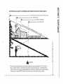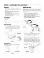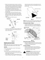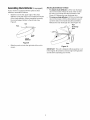
1
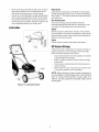
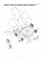
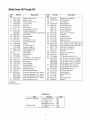
Operator's Manual
21" Rear Discharge
Push Mower
Model Series
410 through 419
IMPORTANT:
Warning:
Read safety rules and instructions
This unit is equipped with an internal combustion
carefully
before operating
equipment.
engine and should not be used on or near any unimproved forest-cov-
ered, brush-covered or grass-covered land unless the engine's exhaust system is equipped with a spark arrester meeting applicable
local or state laws (if any). If a spark arrester is used, it should be maintained in effective working order by the operator. In the State
of California the above is required by law (Section 4442 of the California Public Resources Code). Other states may have similar laws.
Federal laws apply on federal lands. A spark arrester for the muffler is available through your nearest engine authorized service dealer
or contact the service department, P.O. Box 361131 Cleveland, Ohio 44136-0019.
MTD LLC, P.O. BOX361131CLEVELAND,OHIO44136-0019
PRINTED IN U.S.A.
FORM NO. 770-10124E
(10/2003)
TABLEOFCONTENTS
Content
Page
3
6
7
10
Important Safe Operation Practices
Slope Gauge
Assembling Your Lawn Mower
Know Your Lawn Mower
Operating Your Lawn Mower
11
Content
Making Adjustments
Maintaining Your Lawn Mower
Troubleshooting
Illustrated Parts List
Page
12
13
15
16
Warranty
20
FINDINGMODELNUMBER
This Operator's Manual is an important part of your new lawn mower. It will help you assemble, prepare and
maintain the unit for best performance. Please read and understand what it says.
Before you start assembling your new equipment, please locate the model plate on the
equipment and copy the information from it in the space provided below. A sample model plate is
also given below. You can locate the model plate by standing at the operating position and
looking down at the rear of the deck. This information will be necessary to use the
manufacturer's web site and/or help from the Customer Support Department or an authorized
service dealer.
_')ff
P. O. BOX 361131
CLEVELAND,OH 44136
338-228-4683
www.mtdproducts.com
888-888-7318
M,-DLLC
Copy
the model
Copy
the serial
number
number
here:
here:
CUSTOMER
SUPPORT
Please do NOTreturn the unitto the retailer from whichit was purchased,withoutfirst contactingCustomerSupport.
If you have difficulty assembling this product or have any questions regarding the controls, operation or
maintenance of this unit, you can seek help from the experts. Choose from the options below:
Visit mtdproducts.com for many useful suggestions. Click on Customer Support button and
you will get the four options reproduced here. Click on the appropriate button and help is
immediately available.
answer you are
looking for could be just
a mouse
"
f
c//cA awayf
answer
looking
a mouse
aye
for could be just
"
f
cficA away_
If you prefer to reach a Customer Support Representative, please call 1(800) 800-7310.
En ine
The engine manufacturer is responsible for all engine-related issues with regards to
performance, power-rating, specifications, warranty and service. Please refer to the engine
manufacturer's Owner's/Operator's Manual, packed separately with your unit, for more
information.
SECTION1: IMPORTANT
SAFEOPERATION
PRACTICES
WARNING:
This symbol points out important safety instructions which, if not followed, could endanger
the personal safety and/or property of yourself and others. Read and follow all instructions in this manual
before attempting to operate this machine. Failure to comply with these instructions may result in personal
injury. When you see this symbol--HEED
ITS WARNING.
WARNING:
Engine exhaust, some of its constituents, and certain vehicle components
emit chemicals known to State of California to cause cancer and birth defects or other
reproductive
contain or
harm.
WARNING:
This machine was built to be operated according to the rules for safe operation in this
manual. As with any type of power equipment, carelessness or error on the part of the operator can result in
serious injury. This machine is capable of amputating hands and feet and throwing objects. Failure to
observe the following safety instructions could result in serious injury or death.
GeneralOperation
1.
2.
3.
4.
5.
6.
7.
Read this operator's manual carefully in its entirety
before attempting to assemble this machine. Read,
understand, and follow all instructions on the machine
and in the manual(s) before operation. Be completely
familiar with the controls and the proper use of this
machine before operating it. Keep this manual in a safe
place for future and regular reference and for ordering
replacement parts.
This machine is a precision piece of power equipment,
not a plaything. Therefore, exercise extreme caution at all
times. Your unit has been designed to perform one job: to
mow grass. Do not use it for any other purpose.
Never allow children under 14 years old to operate this
machine. Children 14 years old and over should read and
understand the operation instructions and safety rules in
this manual and should be trained and supervised by a
parent. Only responsible individuals who are familiar with
these safe operation rules should use this machine.
Thoroughly inspect the area where the equipment is to
be used. Remove all stones, sticks, wire, bones, toys and
other foreign objects which could be tripped over or
picked up and thrown by the blade. Thrown objects can
cause serious personal injury. Plan your mowing pattern
to avoid discharge of material toward roads, sidewalks,
bystanders and the like. Also, avoid discharging material
against a walt or obstruction which may cause
discharged material to ricochet back toward the operator.
To help avoid blade contact or a thrown object injury, stay
in the operator zone behind the handles and keep
bystanders, helpers, children and pets at least 75 feet
from the machine while it is in operation. Stop machine if
anyone enters the area.
Always wear safety glasses or safety goggles during
operation and while performing an adjustment or repair to
protect your eyes. Thrown objects which ricochet can
cause serious injury to the eyes.
Wear sturdy, rough-soled work shoes and close-fitting
slacks and shirts. Shirts and pants that cover the arms
and legs and steel-toed shoes are recommended. Never
operate this machine in bare feet, sandals, slippery or
light weight (e.g. canvas) shoes.
8.
9.
10.
11.
5.
6.
7.
8.
9.
10.
11.
12.
Do not put hands or feet near rotating parts or under the
cutting deck. Contact with the blade can amputate hands
and feet.
A missing or damaged discharge cover can cause blade
contact or thrown object injuries.
Many injuries occur as a result of the mower being pulled
over the foot during a fall caused by slipping or tripping.
Do not hold on to the mower if you are falling; release the
handle immediately.
Never pull the mower back toward you while you are
walking. If you must back the mower away from a wall or
obstruction, first took down and behind to avoid tripping
and then follow these steps:
a. Step back from the mower to fully extend your
arms.
b. Be sure you are welt balanced with sure footing.
c. Pull the mower back slowly, no more than halfway
toward you.
d. Repeat these steps as needed.
Do not operate the mower while under the influence of
alcohol or drugs.
Do not engage the self-propelled mechanism on units
so equipped while starting engine.
The blade control handle is a safety device. Never
attempt to bypass its operation. Doing so makes the
safety device inoperative and may result in personal
injury through contact with the rotating blade. The blade
control handle must operate easily in both directions and
automatically return to the disengaged position when
released.
Never operate the mower in wet grass. Always be sure of
your footing. A slip and fall can cause serious personal
injury. If you feel you are losing your footing, release the
blade control handle immediately and the blade will stop
rotating within three seconds.
Mow in daylight or good artificial light. Walk, never run.
Stop the blade when crossing gravel drives, walkways
or roads.
If the equipment should start to vibrate abnormally, stop
the engine and check immediately for the cause.
Vibration is generally a warning of trouble.
Shut the engine off and wait until the blade comes to a
complete stop before removing the grass catcher or
unclogging
thechute.
Thecutting
bladecontinues
to
rotate
forafewseconds
aftertheengine
isshutoff.
Never
placeanypartofthebodyinthebladeareauntil
youaresurethebladehasstopped
rotating.
13. Never
operate
mower
without
proper
trailshield,
discharge
cover,
grasscatcher,
bladecontrol
handle
or
othersafety
protective
devices
inplaceandworking.
Never
operate
mower
withdamaged
safety
devices.
Failure
todoso,canresultinpersonal
injury.
14. Muffler
andengine
become
hotandcancause
aburn.Do
nottouch.
15. Onlyusepartsandaccessories
made
forthismachine
by
theoriginal
equipment
manufacturer
(O.E.M).
Failure
to
dosocanresultinpersonal
injury.
16. Ifsituations
occurwhich
arenotcovered
inthismanual,
usecareandgoodjudgment.
Contact
yourdealer
for
assistance.
Telephone
1-800-800-7310
forthename
of
yournearest
dealer.
SlopeOperation
Slopes are a major factor related to slip and fall accidents
which can result in severe injury. Operation on slopes
requires extra caution. If you feel uneasy on a slope, do not
mow it. Before operating this unit on a slope or hilly area, use
the slope gauge on page 6 to measure slopes. If the slope is
greater than 15 degrees, do not mow it.
Do:
1.
2.
3.
8,
6.
Service
Safe HandlingOfGasoline:
1.
2.
3.
4.
5.
6.
Mow across the face of slopes; never up and down.
Exercise extreme caution when changing direction on
slopes.
Watch for holes, ruts, rocks, hidden objects, or bumps
which can cause you to slip or trip. Tall grass can hide
obstacles.
Always be sure of your footing. A slip and fall can cause
serious personal injury. If you feel you are losing your
balance, release the blade control handle immediately,
and the blade will stop rotating within 3 seconds.
7.
8.
9.
10.
Do Not:
1.
2.
3.
Do not mow near drop-offs, ditches or embankments,
you could lose your footing or balance.
Do not mow slopes greater than 15 degrees as shown on
the slope gauge.
Do not mow on wet grass. Unstable footing could cause
slipping.
Children
Tragic accidents can occur if the operator is not alert to the
presence of children. Children are often attracted to the
mower and the mowing activity. They do not understand the
dangers. Never assume that children will remain where you
last saw them.
1.
2.
3.
4.
Keep children out of the mowing area and under the
watchful care of a responsible adult other than the
operator.
Be alert and turn mower off if a child enters the area.
Before and while moving backwards, look behind and
down for small children.
Use extreme care when approaching blind corners,
doorways, shrubs, trees, or other objects that may
obscure your vision of a child or an adult who may run
into the lawn mower.
Keep children away from hot or running engines. They
can suffer burns from a hot muffler.
Never allow children under 14 years old to operate a
power mower. Children 14 years old and over should
read and understand the operation instructions and
safety rules in this manual and should be trained and
supervised by a parent.
11.
12.
13.
14.
15.
To avoid personal injury or property damage use extreme
care in handling gasoline. Gasoline is extremely
flammable and the vapors are explosive. Serious
personal injury can occur when gasoline is spilled on
yourself or your clothes which can ignite.
Wash your skin and change clothes immediately.
Use only an approved gasoline container.
Never fill containers inside a vehicle or on a truck or
trailer bed with a plastic liner. Always place containers on
the ground away from your vehicle before filling.
If possible, remove gas-powered equipment from the
truck or trailer and refuel it on the ground. Otherwise
refuel such equipment on a trailer with a portable
container rather than from a gasoline dispenser nozzle.
Keep the nozzle in contact with the rim of the fuel tank or
container opening at all times until fueling is complete. Do
not use a nozzle lock-open device.
Extinguish all cigarettes, cigars, pipes and other sources
of ignition.
Never fuel machine indoors because flammable vapors
wilt accumulate in the area.
Never remove gas cap or add fuel while the engine is hot
or running. Allow engine to cool at least two minutes
before refueling.
Never over tilt fuel tank. Fill tank to no more than ½ inch
below bottom of filler neck to provide space for fuel
expansion.
Replace gasoline cap and tighten securely.
If gasoline is spilled, wipe it offthe engine and
equipment. Move unit to another area. Wait 5 minutes
before starting the engine.
Never store the machine or fuel container inside where
there is an open flame, spark or pilot light as on a water
heater, space heater, furnace or other gas appliances.
To reduce fire hazard, keep mower free of grass, leaves,
or other debris build-up. Clean up oil or fuel spillage and
remove any fuel soaked debris.
Allow a mower to cool at least 5 minutes before storing.
GeneralService:
1.
2.
3.
Never run an engine indoors or in a poorly ventilated
area. Engine exhaust contains carbon monoxide, an
odorless and deadly gas.
Before cleaning, repairing, or inspecting, make certain
the blade and all moving parts have stopped. Disconnect
the spark plug wire and ground against the engine to
prevent unintended starting.
Check the blade and engine mounting bolts at frequent
intervals for proper tightness. Also, visually inspect blade
4.
5.
6.
7.
8.
9.
fordamage
(e.g.,bent,cracked,
worn)Replace
blade
withtheoriginal
equipment
manufacture's
(O.E.M.)
blade
only,listedinthismanual.
"Useofpartswhichdonot
meettheoriginal
equipment
specifications
mayleadto
improper
performance
andcompromise
safetyF
Mower
blades
aresharpandcancut.Wrapthebladeor
weargloves,
anduseextracaution
whenservicing
them.
Keepallnuts,bolts,andscrews
tighttobesurethe
equipment
isinsafeworking
condition.
Never
tamper
withsafety
devices.
Check
theirproper
operation
regularly.
Afterstriking
aforeign
object,
stoptheengine,
disconnect
thesparkplugwireandground
against
theengine.
Thoroughly
inspect
themower
foranydamage.
Repair
thedamage
before
starting
andoperating
themower.
Never
attempt
tomakeawheelorcutting
height
adjustment
whiletheengine
isrunning.
Grass
catcher
components,
discharge
cover,andtrail
shield
aresubject
towearanddamage
whichcould
expose
moving
partsorallowobjects
tobethrown.
For
safety
protection,
frequently
checkcomponents
and
replace
immediately
withoriginal
equipment
manufacturer's
(O.E.M.)
partsonly,listedinthismanual.
"Useofpartswhichdonotmeettheoriginal
equipment
specifications
mayleadtoimproper
performance
and
compromise
safetyF
10. Donotchange
theengine
governor
setting
oroverspeed
theengine.
Thegovernor
controls
themaximum
safe
operating
speed
oftheengine.
11. Maintain
orreplace
safety
andinstruction
labels,
as
necessary.
12. Observe
proper
disposal
tawsandregulations.
Improper
disposal
offluidsandmaterials
canharmthe
environment.
YourResponsibility
•
Restrict the use of this power machine to persons
who read, understand and follow the warnings and
instructions in this manual and on the machine.
Some of the safety labels are reproduced below for
information purposes. Maintain safety by following
these labels.
/ WARNING
#AN
8R
O0
m
USE THIS PAGE AS A GUIDE TO DETERMINE SLOPES WHERE YOU MAY NOT OPERATE SAFELY.
SIGHT AND HOLD THIS LEVEL WITH A VERTICAL
A POWER
I "If
.J..
I
I '111
I
I
I _
i
I
" FOLD
I
='_
Z
TREE
POLE
A CORNER
0^,_
--I
OF A BUILDING
OR A FENCE POST
mo
m
I
,v/.jO-
.....
=,'_/_
m
I
O
c
03
>
r-
O
z
©
15 °
O
--t
--t
I-r1
I--
_
WARNING
Do not mow on inclines with a slope in excess of 15 degrees (a rise of approximately 2-1/2 feet every 10
feet). On steeper inclines, a riding mower could overturn and cause serious injury. If operating a walkbehind mower on such a slope, it is extremely difficult to maintain your footing and you could slip, resulting
in serious injury. Operate RIDING mowers up and down slopes, never across the face of slopes.
Z
I-1"1
SECTION3: ASSEMBLING
YOURLAWNMOWER
Unpacking
AssemblingHandle
•
Remove staples, break glue on top flaps, or cut
tape at carton end and peel along top flap to open
carton.
•
Remove loose parts if included with unit (i.e.,
owner's manual, etc.).
Cut along corners and lay carton down flat.
Remove packing material.
Roll or slide unit out of carton. Check carton
•
•
•
NOTE: Stand behind the mower as if you were going to
operate it. Your right hand corresponds to the right side
of the mower; your left hand corresponds to the left side
of the mower.
•
•
thoroughly for loose parts.
•
ToolsRequired
1.
2.
Remove any packing material which may be
between the upper and lower handles.
Pull up and back on the upper handle to raise the
handle into the operating position.
Make certain the lower handle is seated securely
into the handle mounting brackets.
Pair of Pliers
Funnel
Tighten
hand knob
NOTE: This operator's manual covers various models
of lawn mowers. Follow only those instructions which
pertain to your unit.
BeforeAssembly
•
•
Disconnect spark plug wire from the spark plug,
and ground it against the engine. See Figure 1.
If engine is equipped with a rubber boot, attach
rubber boot to a bolt on the engine to ground.
/
Tighten
hand knob
/i
Figure 3
Spark Plug
•
/
•
•
Figure 1
The upper handle is attached to the lower handle
with a handle knob and a carriage bolt on each
side. See Figure 3. Tighten these hand knobs.
Make sure that each carriage bolt is seated
properly on the handle.
Locate hairpin clip in one hole on the weld pin on
each side of the lower handle. See Figure 4.
Remove hairpin clip from this hole. Using a pair of
pliers, insert the hairpin clip into the other hole on
the weld pin. See Figure 4. Repeat on other side.
,\
HardwarePack
Please identify each piece of the hardware pack as
shown in Figure 2 here.
Carriage
Wing Nut
Hairpin
Wing Nut (2)
Carriage Bolt (2)
Figure 2
Weld
Figure 4
•
•
•
•
Refer to the hardware pack in Figure 2. Insert the
carriage bolt from the hardware pack into the upper
hole on the handle mounting bracket. See Figure 4.
Secure with one plastic wing nut, also included in
the hardware pack. Repeat on the other side with
remaining items from the hardware pack.
The rope guide is attached to the right side of the
upper handle. Loosen the wing nut which secures
the rope guide.
Hold the blade control handle against the upper
handle, and pull the starter rope out of the engine.
Release the blade control handle. Slip the starter
rope into the rope guide. Tighten the wing nut. See
Figure 5.
Tighten all nuts and bolts securely.
Slip rope into
rope g
channels except center top of bag attach from the
outside of bag. Center top of bag attaches from the
inside of bag.
Center top of bag
Hook
/
/
/
Grass Bag
Wing Nut
Plastic Channel
Figure 7
NOTE: Once the grass bag has been attached to the
frame, the whole assembly is called a Grass Catcher.
AttachingGrass Catcher To Mower
•
Figure 5
Lift the rear discharge door and place the grass
catcher on the pivot rod. Let go of discharge door
so that it rests on the grass catcher. See Figure 8.
Rear Discharge
Door
\
Insert post on cable ties into holes provided on the
lower handle. Pull the cable tie tight and trim the
excess. See Figure 6.
Cable Tie
Post
Hole on
Lower
Handle
Figure 8
Figure 6
AttachingGrassCatcher
NOTE: Make certain bag is turned right side out before
assembling (warning label will be on the outside).
Assembly
Grass Catcher Assembly consists of the following:
1.
2.
Frame Assembly
Grass bag
RemovingGrassCatcherFrom Mower
•
Lift the rear discharge door on the mower as shown
in Figure 8. Lift grass catcher up and out of the pivot
rod. Release rear discharge door.
Converting To Mulcher
•
Lift the rear discharge door on the mower and
remove the grass catcher. Release the discharge
door to allow it to close the rear opening of the
mower. Now it is ready to mulch.
Follow steps below to assemble the grass catcher:
•
•
Place bag over frame so that its black plastic side is
at the bottom. See Figure 7.
Slip the plastic channel of the grass bag over the
hooks on the frame. See Figure 7. All of the plastic
_
Never
unless
theARNING:
hooks on the
grassoperate
catcher mower
are firmly
seated in the slots on the handle bracket
assemblies, and the rear discharge door rests
firmly against top of the grass catcher.
Assembling
ChuteDeflector(ifequipped)
If your mower is equipped with the optional chute
deflector, assemble as follows:
•
Slide the rod into the upper edge of the chute
deflector so the tab on the rod is toward the left side
of the chute deflector. When assembled correctly,
the rod will extend further to the left side. See
Figure 9.
Tab
Rod
AttachingChuteDeflectorTo Mower
•
•
To attach chute deflector: Lift the rear discharge
door on the mower. Place the ends of the rod into
the slots in the handle bracket assemblies. See
Figure 10. Release the rear discharge door.
To remove chute deflector: Lift the rear discharge
door on the mower. Lift the chute deflector up and
out of the slots in the handle bracket assemblies.
Release the rear discharge door. See Figure 10.
Rear
J Discharge
Door
/
Chute
Deflector
Figure 9
•
Slide the push nut onto the right side of the rod to
secure.
Slots
Figure 10
IMPORTANT: This unit is shipped without gasoline or oil
in the engine. Be certain to service engine with gasoline
and oil before operating your mower.
SECTION4: KNOWYOURLAWNMOWER
Compare the illustrations in Figure 11 with your lawn mower to familiarize yourself with the location of various
controls and adjustments.
Blade Control Handle
Upper Handle
Recoil Starter
Bag-Fill Indicator (if equipped)
Lower Handle
Grass Catcher
Oil Fill/Dipstick
/
/--
Spark Plug
Gasoline Fill
Cutting Height Adjustment
Lever (Only two of four
are called out.)
Figure 11
BladeControlHandle
CuttingHeightAdjustmentLever
These levers are located on each wheel and are used
to adjust the cutting height. All four levers have to be at
the same relative position to ensure uniform cut.
The blade control handle is located on the upper handle
of the mower. Depress it and squeeze against the
upper handle to operate the unit. Release the blade
control handle to stop the engine and blade.
_
Bag-Fill Indicator (if equipped)
Some mowers are equipped with a bag-fill indicator on
the grass catcher to add convenience to your work. If
the grass catcher is empty, air flows through the
indicator and pushes the "sail" up. If the grass catcher is
full, air does not flow through it and the "sail" falls. So
the position of the "sail" in the bag-fill indicator indicates
how full the grass bag is.
a safety
ARNING"
device.The
Never
blade
attempt
controlto mechanism
bypass it. is
RecoilStarter
The recoil starter handle is attached to the handle and
is used to start the engine.
10
SECTION5: OPERATING
YOURLAWNMOWER
ToStopEngine& Blade
,_
from the chute area
cutting
Refer to
WARNING:
Keep on
hands
anddeck.
feet away
warning label on the unit.
•
•
GasandOilFill-Up
•
Service the engine with gasoline and oil as
instructed in the engine manual packed with your
mower. Read instructions carefully.
,_
UsingRotaryMower
_
WARNING"
Never fill or
the(iii)
fuelif engine
tank (i) has
indoors,
(ii) with engine running,
not
sufficiently cooled down. Wait at least two
minutes after stopping the engine.
•
Attach spark plug wire to spark plug. Refer to
Figure 1. If the mower is equipped with a rubber
boot over the end of the spark plug wire, make sure
that metal cap inside the rubber boot is fastened
securely over the spark plug's metal tip.
,_
Firmly push primer three times. See Figure 12A.
A
Push
release to
prime
Squeeze these two
handles
For best results, do not cut wet grass because it
tends to stick to the underside of the mower.
•
For a healthy lawn, never cut more than one-third of
the total length of the grass at any one cutting.
B
NOTE: For shipping purposes your mower wheels are
set in a low cutting height position. Raise the cutting
height to a position best suited for your lawn. Refer to
page 12 for instructions.
Usingas Mulcher
For mulching grass, remove the grass catcher from the
mower. The rear discharge opening should be closed.
C
Pull
Recoil Starter
•
Figure 12
•
WARNING:
If the mower
strikes a
foreign
object and/or vibrates
excessively,
stop
the
•
•
•
•
Be sure that lawn is clear of stones, sticks, wire, or
engine. Remove spark plug wire, thoroughly
inspect for any damage, and repair the damage
before restarting.
ToStartEngine& EngageBlade
•
ARNING:
Never
mower
without
either the
rear operate
door or your
the entire
grass
catcher assembly firmly secured.
other objects before starting to operate the mower.
BeforeStarting
•
Release the blade control handle to stop the engine
and the cutting blade.
Disconnect the spark plug wire and ground it
against the engine.
Standing behind the lawn mower, squeeze the
blade control handle against the upper handle. See
Figure 12B.
Holding both handles firmly, pull rope out slowly
from the recoil starter. See Figure 12C. Let the rope
rewind slowly. Repeat this motion till engine starts.
For effective mulching, do not cut wet grass.
New or thick grass may require a narrower cut. The
ground speed should be adjusted to the condition
of the lawn.
Do not mulch if grass is taller than 4 inches. Use the
grass catcher to bag clippings instead.
BaggingGrassClippings
You can use the grass catcher to collect clippings while
you are operating the mower.
•
whenever the engine
WARNING"
The blade
is running.
will be rotating
Keep your
hands and feet away from a rotating blade.
•
completely before
WARNING"
Waitdoing
for the
any
blade
worktoonstop
the
mower or to remove the grass catcher.
•
11
Attach grass catcher following instructions on page
8. Grass clippings will automatically collect in the
bag as you run the mower. Operate the mower till
the grass bag is full. Refer to page 10 for
description of flow indicator, if so equipped.
Stop engine completely by releasing the blade
control handle. Make sure that the unit has come to
a complete stop.
Lift discharge door and pull grass bag up and away
from the mower to dispose of the grass clippings.
SECTION6: MAKINGADJUSTMENTS
on the handle brackets. Attach the starter rope as
instructed in the Assembly section.
_
ARNING"to lawn
Do not
at any
time make
adjustment
mower
without
first any
stopping the engine and disconnecting the
spark plug wire.
CuttingHeight
An adjusting plate and thumb lever at each wheel
position provides cutting height adjustment. Each
adjusting plate has nine height positions.
HandleHeight
The mower is shipped with the handle at a higher height
position. To lower the handle height, proceed as
follows.
•
•
•
Remove the starter rope from the rope guide.
Remove the hand knobs, washers and carriage
bolts securing the upper handle to the lower
handle. Lay the upper handle out of the way, being
careful not to bend or kink the cables.
•
Remove the hairpin clips from the weld pins on the
handle brackets. Press outward on the legs of the
lower handle, and remove it from the mower.
Remove the carriage bolts and wing nuts from the
handle brackets. Press out on the legs of the lower
handle. Remove lower handle from the mower.
Turn the lower handle around so the notches on the
•
bottom of the lower handle are facing forward as
shown in Figure 13.
Place the bottom holes of the handle over the weld
•
•
Simply depress the lever towards wheel and move
it to any of the nine positions for the desired cutting
height. See Figure 14. All four levers on the four
wheels must be placed in the same relative position
for uniform cutting height
Height
Adjustment
J Lever
Figure
pins in the handle mounting bracket. Reattach the
hardware.
14
Carburetor
Minor carburetor adjustments may be required to
compensate for differences in fuel, temperature,
altitude and load. To adjust carburetor, refer to the
engine manual.
Lower
Handle
NOTE: A dirty air cleaner will cause an engine to run
rough. Be certain air cleaner is clean and attached to
the carburetor before adjusting carburetor.
Notch
Figure 13
•
•
,_
Reassemble the upper handle.
Place the hairpin clips in the inner holes of the weld
pins and replace the carriage bolts and wing nuts
12
the engine whileIf the
WARNING:
any engine
adjustments
is running
are made
(e.g. to
carburetor), keep clear of all moving parts. Be
careful of heated surfaces and muffler.
SECTION7: MAINTAININGYOURLAWNMOWER
BladeMountingTorque:
Center Bolt: 450 in. Ibs. min., 600 in. Ibs. max.
_
ARNING"
Beplug
surewire
to disconnect
and
ground
the spark
before performing
any repairs or maintenance.
IMPORTANT: To ensure safe operation of your unit,
periodically check all nuts and bolts and tighten if
necessary.
MaintainingtheBlade
•
_i
DeckCare
Periodically inspect the blade adapter for cracks,
especially if the mower strikes a foreign object.
Replace blade if crack or any damage is found.
NOTE: We do not recommend the use of pressure
washers or garden hose to clean your unit. These may
cause damage to electric components,
spindles,
pulleys, bearings or the engine. Use of water will
shorten life of the mower and reduce its serviceability.
WARNING"
When or
removing
the cutting
blade
for sharpening
replacement,
protect
hands by using heavy gloves or a rag to grasp
the cutting blade.
Tilt the mower and scrape underside of the deck
after each use to remove grass clippings, leaves or
dirt. If this debris is allowed to accumulate, the deck
may start to rust.
Remove the bolt and bell support which hold the
blade and adapter to the engine crankshaft. See
Figure 14. Remove the blade and adapter from the
crankshaft.
ReplacingRearFlap
Crankshaft
•
•
Blade
Adapter
.
Figure
•
•
•
•
To remove rear flap, cut off the flat end of the wire
rod which secures it to the deck. See Figure 16.
Attach the new flap and new rod to deck, bending
the ends of the new rod over to secure to deck.
Support
HexBell
Bolt
Handle
Bracket
15
When sharpening the blade, follow the original
angle of grind. Grind each cutting edge equally to
keep the blade balanced. An unbalanced blade will
cause excessive vibration when rotating at high
speed. This may damage the mower and/or cause
personal injury.
The blade can be tested by balancing it on a round
shaft screwdriver. Always remove blade from the
adapter for testing balance. Remove metal from the
heavy side until it balances evenly.
Before reassembling the blade and the blade
adapter to the unit, lubricate the engine crankshaft
and the inner surface of the blade adapter with light
oil (or engine oil). Also lubricate the bolt holes, bolts
and inner surface of the nuts.
Install the blade adapter on the crankshaft with the
"star" away from the engine. Place the blade with
the side marked bottom (or with part number) facing
away from the adapter. Align the blade bell support
over the blade with tabs in the holes of the blade
and insert the hex bolt. Tighten the hex bolt to the
torque listed here.
__DoorRear
Discharge
__
Bracket
\,
\
Rear
Flap
Figure 16
Engine
A list of key engine maintenance jobs required for good
performance by the mower is given below. Follow the
accompanying engine manual for detailed list and
instructions.
Maintain engine oil level as instructed in engine
manual.
Service air cleaner every 25 hours under normal
conditions. Clean every few hours under extremely
dusty conditions. Poor engine performance and
flooding usually indicates that the air cleaner should
be serviced. To service the air cleaner, refer to the
engine manual.
13
•
•
BladeControl
Clean spark plug and reset the gap once a season.
Spark plug replacement is recommended at the
start of each mowing season. Check engine
manual for correct plug type and gap specifications.
Clean engine regularly with a cloth or brush. Keep
the cooling system (blower housing area) clean to
permit proper air circulation. Remove all grass, dirt
and combustible debris from muffler area.
Lubricate the pivot points on the blade control handle
and the brake cable at least once a season with light oil.
See Figure 17. The blade control must operate freely in
both directions.
Rear DischargeDoor
The torsion springs and pivot points should be
lubricated periodically with light oil to prevent any rust
or binding. The discharge door must work freely.
Lubrication
Wheels
Wheels require no lubrication. However, if the wheels
are removed for any reason, lubricate the surface of the
axle bolt and the inner surface of the wheel with light oil.
Engine oil may also be used.
Engine
Follow engine manual for lubrication instructions.
Off-Season
Storage
If the lawn mower is not going to be used for 30 days or
longer, prepare the unit for storage. Follow the steps
below for proper storage of the mower.
•
Clean and lubricate mower thoroughly as described
in the lubrication instructions.
•
Refer to engine manual for correct engine storage
instructions.
•
Coat mower's cutting blade with chassis grease to
prevent rusting.
Store mower in a dry, clean area. Do not store next
to corrosive materials, such as fertilizer.
•
NOTE: When storing any type of power equipment
an unventilated or metal storage shed, care should
taken to rust-proof the equipment. Using a light oil
silicone, coat the equipment, especially cables and
moving parts.
Figure 17: Lubrication Chart
14
in
be
or
all
SECTION8: TROUBLE
SHOOTING
GUIDE
Trouble
Possible Cause(s)
Corrective Actions
Engine fails to
start
1.
2.
3.
4.
5.
1.
2.
3.
4.
5.
Engage blade control handle.
Connect wire to spark plug.
Refer to the engine manual.
Refer to the engine manual.
Move throttle lever to FAST or START position.
6.
7.
8.
9.
Blade control handle disengaged.
Spark plug wire disconnected.
Dirty aircteaner.
Primer button not depressed.
Throttle control lever (if so equipped) not in
correct starting position.
Fuel tank empty or stale fuel.
Blocked fuel line
Faulty spark plug.
Engine flooded.
6.
7.
8.
9.
Fill tank with clean fresh gasoline.
Clean fuel line.
Clean, adjust gap or replace.
Refer to the engine manual.
Engine runs
erratic
1.
2.
3.
4.
5.
6.
Spark plug wire loose.
Blocked fuel line, if equipped, or stale fuel.
Vent in gas cap plugged.
Water or dirt in fuel system.
Dirty air cleaner.
Carburetor out of adjustment.
1.
2.
3.
4.
5.
6.
Connect and tighten spark plug wire.
Clean fuel line; fill tank with clean, fresh gasoline.
Clear vent or threads or replace.
Drain fuel tank. Refill with fresh fuel.
Refer to the engine manual.
Refer to the engine manual.
Engine
overheats
1.
2.
3.
Engine oil level tow.
Dirty aircleaner.
Air flow restricted.
1.
2.
3.
4,
Carburetor not adjusted properly.
4.
Fill crankcase with proper oil.
Refer to the engine manual.
Stop engine and disconnect spark plug wire.
Remove blower housing and clean.
Refer to the engine manual.
Occasionally
skips at high
speed
1.
2.
Spark plug gap too close.
Carburetor idle mixture adjustment
improperly set.
1.
2.
Adjust gap to .030".
Refer to the engine manual packed with your unit.
Idles poorly
1.
2.
3.
Spark plug fouled, faulty or gap too wide.
Carburetor improperly adjusted.
Dirty air cleaner.
1.
2.
3.
Reset gap to .030" or replace spark plug.
Refer to the engine manual.
Refer to the engine manual.
Excessive
vibration
1.
2.
Cutting blade loose or unbalanced.
Bent cutting blade.
1.
2.
Tighten blade and adapter. Balance blade.
See an authorized service dealer.
Mower witt not
mulch grass
1.
2.
Wet grass.
Excessively high grass.
1,
2.
Do not mow when grass is wet; wait until later to cut.
Mow once at a high cutting height, then mow again
at desired height or make a narrower cutting swath
(1/2 width).
Uneven cut
1.
2.
Wheels not positioned correctly.
Dull blade.
1.
2.
Place all four wheels in same height position.
Sharpen or replace blade.
NOTE: For repairs beyond those listed above, contact an authorized service dealer or call 1(800)800-7310.
15
SECTION9: PARTSLISTFORMODELSERIES410THROUGH
419
11
\
lo_.
/2
20
16
21
22
34
48
\54
Zag Tread Wheel
22
Bar Tread Wheel
16
ModelSeries410Through419
Ref.
No.
1.
2.
3.
7.
8.
9.
10.
11.
12.
13.
14.
15.
16.
17.
18.
19.
20.
21.
22.
23.
24.
25.
26.
27.
28.
29.
30.
31.
32.
Part No.
747-1161A
749-1092A
747-04080
749-0928A
720-0279
710-1205
710-1174
664-04005
764-0650
720-0284
736-0451
726-0240
710-0703
731-04134
750-04162
732-04089
732-04090
787-01144
787-01143
$
782-5003
731-0981A
787-01103
710-1017
782-5002A
748-0376C
742-0741
710-1044
736-0524A
15261A
687-02077
687-02077
687-02076
687-02076
720-0426
Ref.
No.
33.
34.
36.
38.
39.
Description
Blade Control Handle
Upper Handle
Grass Catcher Frame
Lower Handle
Wing Nut
Rope Guide
Carriage Bolt 5/16-18 x 2
Grass Bag Assembly
Grass Bag Assembly w/Bag-Fill
Hand Knob
Saddle Washer
Cable Tie
Ind .-[
40.
41.
42.
43.
44.
45.
46.
Carriage Bolt 1/4-20
Rear Discharge Door
Spacer
Torsion Spring LH
Torsion Spring RH
Handle Bracket RH
Handle Bracket LH
Rear Wheel
Rear Baffle LH
47.
48.
49.
50.
51.
52.
Hubcap 1Cutting Deck: Rear Discharge
AB Screw 1/4-14 x .625"
Front Baffle
Blade Adapter
Mulching Blade
Hex Bolt 3/8-24 x 1.5
53.
Blade Belt Support
Front Adjustment Plate
Pivot Arm Assembly RH (8" wheel)
Pivot Arm Assembly LH (7" wheel)
Pivot Arm Assembly LH (8" wheel)
Pivot Arm Assembly RH (7" wheel)
Knob: Adjustment Lever
54.
55.
56.
57.
58.
59.
60.
Part No.
Description
732-0404
738-0507B
Spring Lever Assembly
Shoulder Screw
Front Wheel
Rear Baffle RH
Control Cable 37.25"
Control Cable 40"
Control Cable 40.5"
Control Cable 53"
$
782-5004A
746-0957
746-1130
746-0554
746-1137
720-0295
731-1236
732-0700
731-1506
712-0397
710-0654A
687-02071
687-02070
787-01132
787-01131
710-1652
712-0431
714-0104
710-0654A
687-02074
687-02100
687-02075
687-02099
687-02069
687-02068
712-0431
747-04035
736-0504
731-1405
711-0996
726-0201
750-0535
Foam Grip 1 (not shown)
Traitshield
Trailshield Wire
Deck: Front Cover 1Wing Nut 1/4-20
Hex L-Washer Hd. Screw 3/8-16 x 1.0
Lever Assembly: Rear Height Adj. RH
Lever Assembly: Rear Height Adj. LH
Pivot Bar: 9 Position RH
Pivot Bar: 9 Position LH
AB Screw
Flange Lock Nut 3/8-16
Hairpin Clip
TT Sems Screw 3/8-16 x 1.0
Ht. Adj. Assy. Front RH (8" Wheel)
Ht. Adj. Assy. Front RH (7" Wheel)
Ht. Adj. Assy. Front LH (8" Wheel)
Ht. Adj. Assy. Front LH (7" Wheel)
Handle Bracket Assy. Rear LH
Handle Bracket Assy. Rear RH
Flange Nut 3/8-16 Thd.
Pivot Rod: Rear Door
Wave Washer 1Chute Deflector 1Rod 1Push Speed Nut1Spacer 1-
I If equipped
:1:Refer to Wheel Chart
_Wheel Chart
Type
Wheels w/o bearing
Wheels w/BB
Part No.
734-1781, Slot Hub
734-1987, 8 x 1.8
734-1988, 7 x 1.8
634-0020, Disc Hub
734-2004A, Disc Hub
734-2005A
17
Tread
Bar
Bar
Bar
Bar
Zag
Zag
YOURNOTES
Date
Comments
18
YOURNOTES
Date
Comments
19
MANUFACTURER'S
LIMITED WARRANTY
The limited warranty set forth below is given by MTD LLC with
respect to new merchandise purchased and used in the
United States, its possessions and territories.
"MTD"warrants this product against defects in material and
workmanship for a period of two (2) years commencing on the
date of original purchase and wilt, at its option, repair or
replace, free of charge, any part found to be defective in
materials or workmanship. This limited warranty shall only
apply if this product has been operated and maintained in
accordance with the Operator's Manual furnished with the
product, and has not been subject to misuse, abuse,
commercial use, neglect, accident, improper maintenance,
alteration, vandalism, theft, fire, water, or damage because of
other peril or natural disaster. Damage resulting from the
installation or use of any part, accessory or attachment not
approved by MTD for use with the product(s) covered by this
manual will void your warranty as to any resulting damage.
Normal wear parts or components thereof are subject to
separate terms as follows: All normal wear parts or
component failures wilt be covered on the product for a period
of 30 days regardless of cause. After 30 days, but within the
two year period, normal wear part failures will be covered
ONLY IF caused by defects in materials or workmanship of
OTHER component parts. Normal wear parts and
components include, but are not limited to: batteries, belts,
blades, blade adapters, grass bags, rider deck wheels, seats,
snow thrower skid shoes, shave plates, auger spiral rubber,
and tires.
HOW TO OBTAIN SERVICE: Warranty service is available,
WITH PROOF OF PURCHASE, through your local authorized
service dealer. To locate the dealer in your area, check your
Yellow Pages, or contact MTD LLC at P.O. Box 361131,
Cleveland, Ohio 44136-0019, or call 1-800-800-7310 or 1330-220-4683 or tog on to our Web site at
www.mtdproducts.com.
This limited warranty does not provide coverage in the
following cases:
a,
b,
C.
The engine or component parts thereof. These items
may carry a separate manufacturer's warranty. Refer
to applicable manufacturer's warranty for terms and
conditions.
Log splitter pumps, valves, and cylinders have a
separate one year warranty.
Routine maintenance items such as lubricants, filters,
blade sharpening, tune-ups, brake adjustments, clutch
adjustments, deck adjustments, and normal
deterioration of the exterior finish due to use or
d,
e,
f.
g,
FOR:
MTD does not extend any warranty for products sold or
exported outside of the United States, its possessions
and territories, except those sold through MTD's
authorized channels of export distribution.
Replacement parts that are not genuine MTD parts.
Service completed by someone other than an
authorized service dealer.
Transportation charges and service calls.
No implied warranty, including any implied warranty of
merchantability of fitness for a particular purpose,
applies after the applicable period of express written
warranty above as to the parts as identified. No other
express warranty, whether written or oral, except as
mentioned above, given by any person or entity,
including a dealer or retailer, with respect to any product,
shall bind MTD. During the period of the warranty, the
exclusive remedy is repair or replacement of the product
as set forth above.
The provisions as set forth in this warranty provide the
sole and exclusive remedy arising from the sale. MTD
shall not be liable for incidental or consequential loss or
damage including, without limitation, expenses incurred
for substitute or replacement lawn care services or for
rental expenses to temporarily replace a warranted
product.
Some states do not allow the exclusion or limitation of
incidental or consequential damages, or limitations on how
long an implied warranty lasts, so the above exclusions or
limitations may not apply to you.
In no event shall recovery of any kind be greater than the
amount of the purchase price of the product sold. Alteration
of safety features of the product shall void this warranty.
You assume the risk and liability for toss, damage, or injury to
you and your property and/or to others and their property
arising out of the misuse or inability to use the product.
This limited warranty shall not extend to anyone other than the
original purchaser or to the person for whom it was purchased
as a gift.
HOW STATE LAW RELATES TO THIS WARRANTY: This
limited warranty gives you specific legal rights, and you may
also have other rights which vary from state to state.
IMPORTANT:Owner must present Original Proof of
Purchase to obtain warranty coverage.
exposu_.
MTD LLC, P.O.BOX361131CLEVELAND,OHIO44136-0019; Phone:1-800-800-7310,1-330-220-4683