1
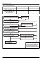
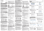
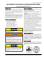
035-17452-000 Rev. B (0106)
ACCESSORY KIT INSTALLATION INSTRUCTIONS
Masonry Chimney Draft Hood Kit
DESCRIPTION
SAFETY STATEMENT
Tile Lined Chimney Kit Model Numbers, 1CK0603 and
1CK0604 permits the venting of an 80% induced draft furnace to be vented into a properly sized masonry lined chimney, without installing a metal liner. The kit can be used on
model series shown in Table 1.
The installer should pay particular attention to the words:
NOTE, CAUTION, AND WARNING.
This kit is only to be used on upflow and counterflow (downflow) installations only. The kit is not intended to be used with
horizontally installed furnaces, or on furnaces where the lateral vent length exceeds the length specified in Table 2. The
Tiled Chimney Kit is certified for use with Natural or LP gas.
INSTALLATION CHECKLIST
•
•
•
•
•
•
•
Select Correct Kit Model (page 3)
Verify Chimney Condition (page 4)
Properly Size Flue Pipe (Table 2 or 3)
Attach Chimney Kit (Figure 4)
Connect Limit Switch Wiring (Figure 5)
Check Kit for Spillage (Page 8)
Place Furnace into Operation (Page 8)
For your safety, read and understand the instructions before installing the kit.
NOTES are intended to clarify or make the installation easier.
CAUTIONS are given to prevent equipment damage.
WARNINGS are given to alert the installer that personal
injury and/or equipment or property damage may occur if
installation procedures are not handled properly.
This furnace should be installed in accordance with all
national and local building and safety codes and requirements, or in the absence of local codes, with the National
Fuel Gas Code, ANSI Z233.1 (latest edition) or in Canada,
The National Canadian Installation Code CAN/CGA B149.1
or B149.2 (latest edition), and other applicable codes.
This furnace shall not be connected to a chimney flue serving
a separate appliance designed to burn solid fuel.
This kit is permitted to be used in any building in which the
space surrounding the furnace is not depressurized by more
than 0.02 in w.c. (5 Pa) below outdoor pressure by equipment
such as exhaust fans or clothes dryers.
Minimum clearances to combustibles for the furnace that the
kit is applied shall be maintained. This kit shall not be used on
any model other than the models listed in Table 1. The room
temperature surrounding the furnaces and vent connections
shall be 60º F (42º C) or warmer.
CHIMNEY INSPECTION
Improper installation may create a condition whree
the operation of the product could cause personal
injury or property damage.
Improper installation, adjustment, alteration, service,
or maintenance can cause injury or property damage. Refer to this manual for assistance or additional information. Consult a qualified installer,
service agency or the gas supplier.
This product must be installed in strict compliance
with the enclosed installation instructions and any
applicable local, state, and national codes including
but not limited to building, elecctrical and mechanical codes.
Unitary Products Group
For venting guidelines, refer to the venting tables in this manual. For additional requirements, refer to the National Fuel
Gas Coce NFPA 54/ANSI Z223.1 and Standard for Chimneys, Fireplaces, Vents, and Solid Fuel Burning Appliances
ANSI/NFPA 221, or The National Canadian Installation Code
CAN/CGA-B149.1 or 149.2 in Canada. Also refer to Figure 1,
Chimney Inspection Chart.
FURNACE SIZING
Size of the furnace not to exceed 50% incremental of the
design heating load. Oversizing beyond 50% incremental of
the design load increases the likelihood of condensate problems.
035-17452-000 Rev. B (0106)
TABLE 1: List of Approved Model Series
Approved Furnace
Model Series
BGU050* - 125*, FG8050* - 125*,
G8C050* - 125*, GF8050* - 125*
BGU150*, FG8D150*, GF8150D*
FC8*, FL8*, GM8*, GR8*, GY8*,
G8*, L8*, P*D*, P4HU,
LC8*, LL8*,LM8*, P*8*, XYF8*, XYG8*
Is the crown missing mortar or brick?
Tile Lined Chimney Kit
Model Number
Furnace
Flue Outlet Size
1CK0603
3”
1CK0604
4”
Yes
Rebuild crown
No
Is the crown missing mortar or brick? No
Yes
Is liner and top seal in good
condition?
No
Repair
Yes
Is there mortar, tile, fuel oil residue
or other debris in the cleanout?
Repair liner or top seal or
Reline
reline chimney as necessary
Yes
No
Is the clay tile misaligned, have
missing sections, or gapped?
Yes
No
Is the chimney exposed to the
outdoors below the roofline?
Yes
Yes
No
Yes
The chimney is acceptable
to use with this kit.
Is the chimney serving one or
No
more draft hooded appliance(s)?
Is the chimney properly sized
for these instructions?
No
Line chimney with the properly sized,
listed flexible metal liner or Type-B vent
per NFGC or National Canadian Code
vent sizing tables, and liner or vent
manufacturer’s installation instructions.
FIGURE 1: Chimney Inspection Chart
2
Unitary Products Group
035-17452-000 Rev. B (0106)
SINGLE APPLIANCE FOR INTERIOR CHIMNEY ONLY
TABLE 2: Vent Table - Interior Chimneys Only
Interior Chimneys Only
Capacity of Masonry Chimney Flue with Type B Dougle-Wall Vent Connectors
Servicing a Single Furnace Equipped with the Tile Lined Chimney Kit
Type B Double-Wall Connector Diameter - D (inches)
To be used with chimney areas within the size limits at the bottom of table
3”
4”
5”
6”
7”
Appliance
Input
Rate
in
Thousands
of
BTU
per
Hour
Chimney
Lateral L
Heights H (ft.)
(ft.)
NAT
NAT
NAT
NAT
NAT
Max.
Max.
Max.
Max.
Max.
2
28
51
86
130
180
6
5
24
49
80
117
165
2
29
55
93
145
18
8
5
26
51
88
134
183
8
24
48
83
127
175
2
31
61
103
163
221
10
5
28
57
96
148
204
10
25
50
87
139
191
2
35
67
114
179
250
5
34
62
107
164
231
15
10
28
55
97
153
216
NR
48
89
141
201
15
2
38
74
124
201
274
5
36
68
116
184
154
20
10
NR
60
107
172
237
NR
NR
97
159
220
15
NR
NR
83
148
206
20
2
41
82
137
216
303
NR
76
128
198
281
5
NR
67
115
184
263
10
30
15
NR
NR
107
171
243
NR
NR
91
159
227
20
NR
NR
NR
NR
188
30
NR
93
161
251
351
2
NR
NR
151
230
323
5
50
NR
NR
138
215
304
10
15
NR
NR
127
199
282
NR
NR
NR
185
264
20
Minimum area of Chimney - A (sq. in.)
12
19
28
38
50
Maximum area of Chimney - A (sq. in.)
49
88
137
198
269
8”
NAT
Max.
247
230
266
247
239
298
277
263
336
313
296
281
375
350
332
314
295
421
393
373
353
332
288
477
445
424
400
376
63
352
1. Seal any unused openings in the venting system. Inspect the venting system for proper size and horizontal pitch, as required in the National Fuel Gas
Code, ANSI Z233.1 or CAN/CGA B149 Canadian Installation Codes, and these instructions. Determine that there is not blockage or restriction, leakage, corrosion and other deficiencies which could cause an unsafe condition.
2. The vent tables are designed for two 90” elbows or equivalent. If additional elbows are used, five feet should be subtracted for each elbow from the
above values.
3. High altitude installation input rates shall be derated starting at 2000 ft. altitude. Sea level input rates shall be used for chimney sizing and venting
guidelines.
4. Vent connector length is limited to 1 1/2 ft. for each inch of vent connector diameter.
5. Vent connectors shall not be upsized more than two sizes greater than the listed appliance vent outlet diameter.
6. For multiple appliance installations, the flow area of the chimney shall not exceed 7 times the smallest draft hood outlet area.
Unitary Products Group
3
035-17452-000 Rev. B (0106)
TYPE “B” DOUBLE WALL
GAS VENT USED
AS CONNECTOR
L
TILE LINED
MASONRY CHIMNEY
D
H
A
FIGURE 2: Single Appliance Vent Connector
MULTIPLE APPLIANCE-INTERIOR OR EXTERIOR CHIMNEY
TABLE 3: Vent Table - Interior or Exterior Chimney
INTERIOR OR EXTERIOR CHIMNEYS
Capacity of Masonry Chimney Flue with Type B Double-Wall Vent Connectors Serving a Furnace Equipped
with the Tile Lined Chimney Kit, and One or More Draft Hooded Appliances
Type B Double-Wall Connector Diameter - D (inches)
To be used with chimney areas within the size limits at the bottom of table
3”
4”
5”
6”
7”
Connector
Appliance Rating Limits in Thousands of BTU per Hour
Chimney
Rise R (ft.)
Height (ft)
NAT
NAT
NAT
NAT
NAT
Largest
Max.
Max.
Max.
Max.
Max.
1
20
40
66
101
141
6
2
28
52
85
124
173
3
34
61
97
143
203
1
22
42
71
108
153
10
2
29
54
87
129
184
3
35
63
100
148
208
1
25
44
74
114
164
15
2
31
55
89
134
192
3
35
64
102
153
215
1
25
46
77
119
173
20
2
31
56
91
138
199
3
35
65
104
157
222
1
25
48
82
127
186
30
2
32
58
95
145
209
3
36
66
107
163
233
1
25
51
89
143
213
50
2
33
61
102
160
235
3
36
69
115
180
260
8”
NAT
Max.
200
232
270
216
247
281
229
260
292
239
270
301
255
287
317
294
326
357
1. Seal any unused openings in the venting system. Inspect the venting system for proper size and horizontal pitch, as required in the National Fuel Gas
Code, ANSI Z233.1 or CAN/CGA B149 Canadian Installation Codes, and these instructions. Determine that there is not blockage or restriction, leakage, corrosion and other deficiencies which could cause an unsafe condition..
2. The vent tables are designed for two 90º elbows or equivalent. If additional elbows are used, five feet should be subtracted for each elbow from the
above values.
3. High altitude installation input rates shall be derated starting at 2000 ft. altitude. Sea level input rates shall be used for chimney sizing and venting
guidelines.
4. Vent connector length is limited to 1 1/2 ft. for each inch of vent connector diameter.
5. Vent connectors shall not be upsized more than two sizes greater than the listed appliance vent outlet diameter.
6. For multiple appliance installations, the flow area of the chimney shall not exceed 7 times the smallest draft hood outlet area.
4
Unitary Products Group
035-17452-000 Rev. B (0106)
INSTALLATION OF CHIMNEY KIT ASSEMBLY
The Tile Lined Chimney Kit is for use on Furnace Models
listed on Page 2.
TYPE “B”
DOUBLE WALL
GAS VENT USED
AS CONNECTOR
A
D
H
D
CONNECTOR
R
RISE “R”
R
SINGLE WALL
OR TYPE “B” VENT
1.
Disconnect power and shut off the gas supply to the furnace.
2.
Turn off gas supply to the furnace at the manual valve.
3.
Remove burner access door.
4.
Remove screw from the front of the chimney kit. Set the
screw aside.
5.
Attach the chimney kit onto the flue outlet of the furnace.
6.
Secure the chimney kit to the furnace with the screw that
was set aside.
7.
Install the black bushing that is provided in the parts bag
of the kit into one of the 7/8” diameter holes located on
the side of the furnace.
FIGURE 3: Multiple Appliance Vent Connector
TABLE 4: Masonry Chimney Liner Dimensions
with Circular Equivalents
Nominal
Liner
Size
(Inches)
4x8
Inside Diameter
of Liner
(Inches)
2 1/2 x 6 1/2
8x8
6 3/4 x 6 3/4
8 x 12
6 1/2 x 10 1/2
12 x 12
9 3/4 x 9 3/4
12 x 16
9 1/2 x 13 1/2
16 x 16
13 1/4 x 13 1/4
16 x 20
13 x 17
20 x 20
16 3/4 x 16 3/4
Unitary Products Group
Inside Diameter Equivalent
or Equivalent
Area
Diameter
(Square
(Inches)
Inches)
4
12.2
5
19.6
6
28.3
7
38.3
7.4
42.7
8
50.3
9
63.6
10
78.5
10.4
83.3
11
95
11.8
107.5
12
113
14
153.9
14.5
162.9
15
176.7
16.2
206.10
18
254.4
18.2
260.2
20
314.10
The wire harness to the kit shall not be routed into
the junction box.
8.
Route the wire harness from the chimney kit into the
burner compartment of the furnace through the bushing.
For counterflow furnaces, route the wire through the
Dgrommet and then into the burner compartment.
The wire harness should be routed above the burner
box to avoid the possibility of any damage to the
wire. (See Figure 4 below).
FIGURE 4: Burner Box
5
035-17452-000 Rev. B (0106)
9.
Remove the red insulated wire from the primary limit
switch and connect it to the chimney kit wire harness
lead.
10. Connect the second lead from the dhimney kit wire harness to the primary limit terminal. (See Figure 5 below).
FIGURE 5: Wire Harness
exhaust fans (range hoods, bathroom fans) not including
summer exhaust fans. Fireplace dampers should be
closed.
4.
Turn on the power to the furnace and open manual gas
valve.
5.
Adjust the thermostat to allow the furnace to operate for
at least 10 minutes.
6.
Once the furnace has operated, check for vent gas spillage at the draft openings with the open flame of a match
or candle.
7.
If the furnace is installed where it is common vented to
another draft hooded appliance(s) (i.e. water heater), follow operating instructions and adjust for continuous
operation.
8.
Check for spillage at the draft hood of the other appliance(s) and again at the chimney kit.
9.
If there is any flue gas spillage from any of the draft
hoods, the vent system and the connections must be
corrected.
11. Secure the wire harness from the chimney kit to the cabinet with the wire clips provided.
10. Once proper installatin and operation are verified, turn
off all the appliances, return fans and vent dampers to
their original position.
12. All excell wire should be fastened inside the furnace with
the cable tie wrap provided in the parts bag.
11. The installation instruction for the chimney kit should be
located near or around the furnace for future reference.
TABLE 5: Parts List
The wire should be secured away from the burner
compartment, or from any live metal or rotating part.
13. Attach the proper size of vent pipe and fasten the pipe to
the chimney kit securely. (See Tables 2 and 3 for proper
size).
INSTRUCTIONS TO PLACE THE FURNACE
INTO OPERATION
Item
Part Number
Quantity
Chimney Kit
1CK0603, 1CK0604
1
Limit Switch
025-27792-003
1
Bushing
025-22638-000
1
WIre Clip
N/A
3
1.
Verify that all the electrical connections that were made
while installing the chimney kit are secure.
Cable Strap
025-16159-000
1
2.
Inspect the vent system for any leakage, corrosion, or
restrictions.
Wire Harness
025-35396-000
1
3.
As practical, close all doors and windows icluding doors
that are in the same room as the furnace. Turn on all
Instruction Manual
035-17453-000
1
6
Unitary Products Group
035-17452-000 Rev. B (0106)
NOTES
Unitary Products Group
7
NOTES
Subject to change without notice. Printed in U.S.A.
Copyright © by York International Corp. 2006. All rights reserved.
Unitary
Products
Group
035-17452-000 Rev. B (0106)
Supersedes: 035-17452-000 Rev. A (0700)
P.O.
Box
19014
Wichita
KS
67204-9014