1
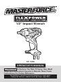
1/2" Impact Wrench
241-0426
OPERATOR’S MANUAL
CAUTION: To Reduce The Risk Of Injury, User Must
Read And Understand Operator’s Manual. Save These
Instructions For Future Reference.
For questions / comments, technical assistance or repair parts –
Please Call Toll Free: 1-866-917-4374. (M-F 8am – 6pm EST.)
TABLE OF CONTENTS
Safety Symbols. . . . . . . . . . . . . . . . . . . . . . . . . . . . . . . . . . . . . . . . . . . . . . . . . . . . . . . . . . Page 2
Safety Instructions. . . . . . . . . . . . . . . . . . . . . . . . . . . . . . . . . . . . . . . . . . . . . . . . . . . . . . . Page 3
Overview/Specifications . . . . . . . . . . . . . . . . . . . . . . . . . . . . . . . . . . . . . . . . . . . . . . . . . . Page 7
Assembly . . . . . . . . . . . . . . . . . . . . . . . . . . . . . . . . . . . . . . . . . . . . . . . . . . . . . . . . . . . . . . Page 8
Operation . . . . . . . . . . . . . . . . . . . . . . . . . . . . . . . . . . . . . . . . . . . . . . . . . . . . . . . . . . . . . . Page 8
Maintenance. . . . . . . . . . . . . . . . . . . . . . . . . . . . . . . . . . . . . . . . . . . . . . . . . . . . . . . . . . . Page 13
Troubleshooting. . . . . . . . . . . . . . . . . . . . . . . . . . . . . . . . . . . . . . . . . . . . . . . . . . . . . . . . Page 13
Warranty. . . . . . . . . . . . . . . . . . . . . . . . . . . . . . . . . . . . . . . . . . . . . . . . . . . . . . . . . . . . . . Page 14
SAFETY SYMBOLS
Some of these following symbols may be used on this tool. Please study them and learn their
meaning. Proper interpretation of these symbols will allow you to operate the tool better and
more safely.
Symbol
Name
Designation / Explanation
V
Volts
Voltage
A
Amperes
Current
Hz
Hertz
Frequency (cycles per second)
W
Watts
Power
∿
Alternating current
Type of current
�
Direct current
Type or characteristic of current
no
No-load speed
Rotational speed at no load
lbs
Pounds
Weight
Class II construction
Double insulated construction
Per minute
Revolutions, strokes, surface speed
orbits, etc., per minute
.../min
Wear safety goggles
WARNING: The operation of any
power tool can result in foreign objects
being thrown into your eyes, which can
result in severe eye damage. Before
beginning power tool operation, always
wear safety goggles or safety glasses
with side shields and a full-face shield
when needed. We recommend a Wide
Vision Safety Mask for use over eyeglasses or standard safety glasses with
side shields. Always use eye protection
which is marked to comply with
ANSI Z87.1.
WARNING: To ensure safety and reliability, all repairs should be performed by a
qualified service technician.
Page 2
SAFETY INSTRUCTIONS
The purpose of safety symbols is to attract your attention to possible dangers. The safety
symbols and the explanations with them deserve your careful attention and understanding.
The symbol warnings do not, by themselves, eliminate any danger. The instructions and
warnings they give are no substitutes for proper accident prevention measures.
WARNING: Be sure to read and understand all safety instructions in this manual,
including all safety alert symbols such as “DANGER,” ”WARNING,” and “CAUTION”
before using this tool. Failure to following all instructions listed below may result in
electric shock, fire, and/or serious personal injury.
SYMBOL MEANING
AFETY ALERT SYMBOL: Indicates DANGER, WARNING, OR CAUTION.
S
May be used in conjunction with other symbols or pictographs.
DANGER: Indicates an imminently hazardous situation, which, if not avoided,
will result in death or serious injury.
WARNING: Indicates a potentially hazardous situation, which, if not avoided,
could result in death or serious injury.
CAUTION: Indicates a potentially hazardous situation, which, if not avoided, could
result in minor or moderate injury.
NOTICE: (Without Safety Alert Symbol) Indicates a situation that may result in property
damage.
SAVE THESE INSTRUCTIONS!
Page 3
SAFETY INSTRUCTIONS
WARNING:
Read all safety
warnings and instructions!
Failure to follow the warnings and instructions
may result in electric shock, fire and/or serious
injury. Save all warnings and instructions for
future reference.
The term power tool in the warnings refers
to your mains-operated (corded) power tool
or battery-operated (cordless) power tool.
WARNING:
Risk of fire and
electric shock. Do not use in rainy or wet
conditions. Use in dry locationd only.
WORK AREA SAFETY
1. Keep the work area clean and well lit.
Cluttered or dark areas invite accidents.
2. Do not operate power tools in explosive
atmospheres, such as in the presence of
flammable liquids, gases or dust. Power
tools create sparks which may ignite the
dust or fumes.
3. Keep children and bystanders away
while operating a power tool. Distractions
can cause you to lose control.
ELECTRICAL SAFETY
1. Power tool plugs must match the
outlet. Never modify the plug in any way.
Do not use any adapter plugs with earthed
(grounded) power tools. Unmodified plugs
and matching outlets will reduce the risk of
electric shock.
2.Avoid body contact with earthed
or grounded surfaces, such as pipes,
radiators, ranges and refrigerators. There
is an increased risk of electric shock if your
body is earthed or grounded.
3. Do not expose power tools to rain or
wet conditions. Water entering a power tool
will increase the risk of electric shock .
4. Do not abuse the cord. Never use the
cord for carrying, pulling or unplugging the
power tool. Keep the cord away from heat,
oil, sharp edges or moving parts. Damaged
or entangled cords increase the risk of
electric shock .
5. When operating a power tool outdoors,
use an extension cord suitable for outdoor
use. Use of a cord suitable for outdoor use
reduces the risk of electric shock.
6. If operating a power tool in a damp
location is unavoidable, use a ground-fault
circuit interrupter (GFCI) protected supply.
Use of a GFCI reduces the risk of electric
shock.
PERSONAL SAFETY
1. Stay alert, watch what you are doing
and use common sense when operating a
power tool. Do not use the tool while tired
or under the influence of drugs, alcohol, or
medication. A moment of inattention while
operating power tools may result in serious
personal injury.
2.Use personal protective equipment.
Always wear eye protection. Protective
equipment, such as a dust mask, non-skid
safety shoes, hard hat, or hearing protection,
used for appropriate conditions, will reduce
the risk of personal injuries.
3. Prevent unintentional starting. Ensure
that the switch is in the off-position before
connecting to the power source and/or
battery pack, picking up or carrying the tool.
Carrying power tools with your finger on the
switch or energizing power tools that have
the switch on invites accidents.
4. Remove any adjusting key or wrench
before turning the power tool on. A wrench
or a key left attached to a rotating part of the
power tool may result in personal injury.
5. Do not overreach. Keep proper footing
and balance at all times. This enables better
control of the power tool in unexpected
situations.
Page 4
SAFETY INSTRUCTIONS
6.Dress properly. Do not wear loose
clothing or jewelry. Keep your hair, clothing
and gloves away from moving parts. Loose
clothes, jewelry or long hair can be caught in
moving parts.
7.If devices are provided for the
connection of dust extraction and
collection facilities, ensure that these are
connected and properly used. Use of these
devices can reduce dust-related hazards.
USE AND CARE OF THE
POWER TOOLS
1. Do not force the power tool. Use the
correct power tool for your application. The
correct power tool will do the job better
and more safely at the rate for which it was
designed.
2. Do not use the power tool if the switch
does not turn it on and off. Any power tool
that cannot be controlled with the switch is
dangerous and must be repaired.
3. Disconnect the plug from the power
source and/or the battery pack from the
power tool before making any adjustments,
changing accessories, or storing power
tools. Such preventive safety measures
reduce the risk of starting the power tool
accidentally.
4. Store idle power tools out of the reach
of children and do not allow persons
unfamiliar with the power tool or these
instructions to operate the power tool.
Power tools are dangerous in the hands of
untrained users.
5.Maintain power tools. Check for
misalignment or binding of moving parts,
breakage of parts and any other condition
that may affect the power tool’s operation.
If damaged, have the power tool repaired
before use. Many accidents are caused by
poorly maintained power tools.
Page 5
6. Keep cutting tools sharp and clean.
Properly maintained cutting tools with sharp
cutting edges are less likely to bind and are
easier to control.
7.Use the power tool, accessories,
tool bits, etc. in accordance with these
instructions, taking into account the
working conditions and the work to be
performed. Use of the power tool for
operations different from those intended
could result in a hazardous situation.
BATTERY TOOL USE
AND CARE
1.Recharge only with the charger
specified by the manufacturer. A charger
that is suitable for one type of battery pack
may create a risk of fire when used with
another battery pack.
2. Use power tools only with specifically
designated battery packs. Use of any other
battery packs may create a risk of injury and
fire.
3. When the battery pack is not in use,
keep it away from other metal objects,
such as paper clips, coins, keys, nails,
screws or other small metal objects that
can make a connection from one terminal
to another. Shorting the battery terminals
together may cause burns or a fire.
4. Under abusive conditions, liquid may
be ejected from the battery; avoid contact.
If contact accidentally occurs, flush with
water. If liquid contacts eyes, also seek
medical help. Liquid ejected from the battery
may cause irritation or burns.
SERVICE
1. Have your power tool serviced by a
qualified repair person using only identical
replacement parts. This will ensure that the
safety of the power tool is maintained.
SAFETY INSTRUCTIONS
SPECIFIC SAFETY RULES FOR
IMPACT WRENCH
1. Use only the batteries and chargers listed
below.
Battery pack
Charger
252-8024
252-8028
252-8029
252-8025
252-8030
252-8036
252-8031
252-8037
252-8032
252-8044
252-8033
252-8034
2. Hold power tools by their insulated
gripping surfaces when performing an
operation where the cutting tool may
contact hidden wiring. Contact with a “live”
wire will make exposed metal parts of the
tool “live” and shock the operator.
3. Use clamps or another practical way to
support the workpiece and secure it to a
stable platform. Holding the work by hand
or against your body is unstable and may
lead to loss of control.
4.Do not drill, fasten or break into
existing walls or other blind areas where
electrical wiring may exist. If this situation
is unavoidable, disconnect all fuses or
circuit breakers feeding the worksite.
5.Always wear safety goggles or eye
protection when using this tool.
6. Bit, sockets and tools get hot during
operation. Wear gloves when touching them
after use .
7. Wear ear protectors when using the
tool for extended periods. Prolonged
exposure to high intensity noise can cause
hearing loss.
8. Use thick, cushioned gloves and limit the
exposure time by taking frequent rest periods.
Vibration caused by impact-wrench action may
be harmful to your hands and arms.
9. Avoid accidental starting. Be sure that
the forward/center-lock/reverse switch is in
the off position before inserting the battery
pack. Carrying appliances with your finger
on the switch or inserting the battery pack
into an appliance with the switch on invites
accidents.
10.
Remove the battery pack before
changing accessories. Accidental starting
may occur, because battery appliances
with a battery inserted are in the operative
condition.
11.Be prepared for a reaction torque when
“seating” or removing a fastener. The tool
housing may tend to twist in the direction
opposite to the bit rotation when “seating”
or removing a fastener, depending on the
torque setting of the tool.
12.Do not use dull or damaged impact
sockets and accessories. When installing
an accessory, insert the impact socket well
onto the output drive. Be sure that the output
drive has locked onto the socket correctly.
13.Do not run the tool while carrying it
at your side. A spinning bit could become
entangled with clothing and injury may
result.
14.Place the tool onto the fastener only
when the tool is switched off. Rotating
driver tools can slide off the fastener.
15.Be careful when driving long screws.
There is a risk of sliding off the fastener
head, depending on the type of socket or bit
used. First test the run-down of a fastener
and pay attention during the screw driving
process to ensure you do not injure yourself
if the tool bit or socket slides off of the
fastener.
Page 6
SAFETY INSTRUCTIONS
DANGER: People with electronic
devices, such as pacemakers, should
consult their physician(s) before using this
product. Operation of electrical equipment
in close proximity to a heart pacemaker
could cause interference or failure of
the pacemaker.
WARNING: Some dust created by
power sanding, sawing, grinding, drilling
and other construction activities contains
chemicals known to the state of California
to cause cancer, birth defects or other reproductive harm. Some examples of these
chemicals are:
• Lead from lead-based paints
• Crystalline silica from bricks and cement
and other masonry products, and
• Arsenic and chromium from chemicallytreated lumber.
Your risk from these exposures varies,
depending on how often you do this type
of work. To reduce your exposure to these
chemicals: work in a well ventilated area,
and work with approved safety equipment,
such as those dust masks that are specially
designed to filter out microscopic particles.
OVERVIEW
FIG. 1
Vents
1/2" Square Drive
Direction-of- Rotation
Selector (Forward/
Center Lock/Reverse)
Variable-Speed
Trigger Switch
LED Worklight
Belt clip
SPECIFICATIONS
Switch
VSR (Variable Speed Reversible)
No-Load Speed
0-2400 RPM
Impacts per minute
0-3200 BPM
Max Torque
1400 in-lbs
Drive
1/2" Square
Weight ( Without battery)
2 lbs. 5 oz. (1.06kg)
Page 7
ASSEMBLY
CONTENTS
Impact wrench, 2 screwdriver bits, 1/2" to
3/8" socket reducer, 1/4" hex adaptor and
instruction manual
UNPACKING
1. This product has been shipped completely
assembled.
2. Carefully remove the tool and any
accessories from the box. Make sure
that all items listed in the contents are
included.
3. Inspect the tool carefully to make sure
that no breakage or damage occurred
during shipping.
4. Do not discard the packing material
until you have carefully inspected and
satisfactorily operated the tool.
OPERATION
TO ATTACH BATTERY
PACK (FIG. 2)
FIG. 2
TO DETACH BATTERY
PACK (FIG. 2)
1. Lock the trigger switch on the impact
wrench by placing the direction of
rotation (forward/center lock/reverse)
selector in the center position.
ATTACH
2. Depress the battery release buttons
located on the front of the battery pack
to release the battery pack.
DETACH
1. Lock the trigger switch on the impact
wrench by placing the direction of
rotation (forward/center-lock/reverse)
selector in center position.
3. Pull the battery pack out and remove it
from the tool.
WARNING: Battery tools are
always in operating condition. Therefore,
the direction-of-rotation selector should
always be locked when not in use or
carrying at your side.
2. Align the raised rib on the battery pack
with the grooves of the wrench, and then
attach the battery pack to the wrench.
NOTICE: When placing the battery pack on
the tool, be sure that the raised rib on the
battery pack aligns with the groove inside
the wrench and that the latches snap into
place properly. Improper attachment of the
battery pack can cause damage to internal
components.
Page 8
OPERATION
TRIGGER SWITCH (FIG. 3)
FIG. 3
DIRECTION-OF-ROTATION
SELECTOR (FORWARD/CENTERLOCK/REVERSE) (FIG. 4)
FIG. 4
Directionof-Rotation
Selector
Variable
Speed
Trigger
Switch
Forward Reverse
To turn the Impact Wrench ON, depress the
trigger switch.
To turn it OFF, release the trigger switch.
VARIABLE SPEED (FIG. 3)
The variable-speed trigger switch delivers
higher speed with increased trigger pressure
and lower speed with decreased trigger
pressure.
The direction of rotation is reversible and
is controlled by a selector located above
the trigger switch. With the Impact Wrench
held in normal operating position: Position
the direction-of-rotation selector to the left
of the tool for forward rotation. Postion the
direction-of-rotation selector to the right
of the tool for reverse rotation. Setting the
switch in the OFF (center-lock) position
helps to reduce the possibility of accidental
starting when not in use.
NOTICE: To prevent gear damage, always
allow the Impact Wrench to come to
a complete stop before changing the
direction of rotation.
NOTICE: The Impact Wrench will not run
unless the direction of the rotation selector
is engaged fully to the left or right.
ELECTRIC BRAKE
To stop the Impact Wrench, release the trigger switch and allow the tool to come to a
complete stop. The electric brake
quickly stops rotating. This feature engages
automatically when you release the trigger
switch.
Page 9
OPERATION
LED WORKLIGHT (FIG. 5)
FIG. 5
LED
Worklight
REMOVING THE BELT CLIP
1. Use a screwdriver to loosen the screw
that attaches the belt clip to the wrench.
2. Remove the screw and the belt clip.
BIT STORAGE (FIG. 7)
FIG. 7
The LED worklight, located on the base of
the Impact Wrench, will illuminate when the
trigger switch is depressed. This provides
additional light on the surface of the
workpiece for operation in lower-light areas.
The LED worklight will turn off when the
trigger switch is released.
INSTALLING THE BELT
CLIP (FIG. 6)
Bit
storage
When not in use, the bit may be stored on
the impact wrench by snapping the bit into
place in the bit clip.
FIG. 6
Belt clip
1. Align the rib of the belt clip with the hole
on the base of the wrench.
2. Insert the screw and tighten the screw
securely with a screwdriver.
Page 10
OPERATION
INSTALLING AND REMOVING
THE SOCKET (FIG.8)
FIG. 8
3. Place the direction-of-rotation selector
in the FORWARD position. Hold the
tool firmly while depressing the trigger
switch. The impact socket will turn the
fastener and impacting will begin once
the fastener encounters resistance.
WARNING: Do not over-tighten, as
the force of the Impact Wrench can break
the fastener.
To loosen:
1. With the proper impact socket securely
mounted to the wrench, slide the impact
socket onto the bolt head.
Always use the correct size socket for bolts
and nuts. An incorrect socket will result
in inaccurate and inconsistent fastening
torque and/or damage to the bolt or nut.
1. Lock the trigger switch by placing the
direction-of-rotation selector in the OFF
(center) position.
2. To install the socket, push it onto the
output drive of the tool until it locks into
place.
3. To remove the socket, simply pull it off.
INSTALLING FASTENERS
NOTICE: Always keep the Impact Wrench
at a right angle to the fastener to avoid
damaging the fastener head.
To fasten:
1. Start threading the fastener by hand
onto or into its threaded counterpart
(e.g. nut onto bolt, or bolt into nut or
threaded hole).
2. With the proper impact socket securely
mounted to the wrench, slide the impact
socket onto the nut or bolt head.
Page 11
2. Place the direction-of-rotation selector
in the REVERSE position. Hold the tool
firmly
while depressing the trigger
switch. The tool will start to impact
immediately.
3. Once the fastener has “broken loose,”
it will start to unthread. Be careful that
you do not allow a fastener to spin
freely once it is no longer engaged with
its threaded counterpart, as it may be
thrown out of the socket.
Impacting tips
The proper fastening torque may differ
depending on the type or size of the bolt, the
material of the workpiece to be fastened,
etc.
NOTICE: Hold the tool straight along the
axis of the bolt or nut.
NOTICE: Excessive fastening torque may
damage the bolt/nut or socket. Before
starting your job, always perform a
test operation to determine the proper
fastening time for your bolt or nut.
OPERATION
Practice with various fasteners, noting the
length of time required to reach the desired
torque. Check the tightness with a handtorque wrench. If the fasteners are too tight,
reduce the impacting time. If they are not
tight enough, increase the impacting time.
Hold the tool firmly, and place the socket
over the bolt or nut. Turn the tool on, and
fasten the bolt or nut to the proper torque.
The torque that is required to loosen a
fastener averages 75% to 80% of the
tightening torque, depending on the
condition of the contacting surfaces.
However, if rust or corrosion causes seizing,
more torque may be required.
After fastening, always check the torque
with a torque wrench. The fastening torque
is affected by a wide variety of factors,
including the following:
•Technique
The manner of holding the tool or the
material to be fastened will affect the
torque.
INSTALLING OR REMOVING
BITS (FIG.9)
FIG. 9
Front sleeve
Back sleeve
•Socket
Failure to use the correct size socket will
cause a reduction in the fastening torque.
A worn socket (wear on the hex end or
square end) will cause a reduction in the
fastening torque.
•Bolt
Although the torque coefficient and the
class of bolt may be the same, the proper
fastening torque will differ according to
the diameter of the bolt.
Even if the diameters of bolts are the
same, the proper fastening torque will
differ according to the torque coefficient,
the class of bolt and the bolt length.
•Accessories
The use of a universal joint or an extension
bar (both available separately) will reduce
the fastening force of the impact wrench
somewhat. Compensate by fastening for
a longer period of time.
1. Lock the trigger switch by placing the
direction-of-rotation selector in the OFF
(center) position.
2. To install a 1/4” hex adaptor, pull the
back sleeve of the 1/4” hex adaptor
forward and press the hex adaptor onto
the square drive. Make sure that the
steel retention ball engages into the
hole on the square drive. To remove the
hex adaptor, simply grip the back sleeve
and pull it off.
3. To install the bit, pull the front sleeve
forward, hold it in place, insert a 1/4”
bit into the hexagonal chuck, and then
release the sleeve. Check that the sleeve
returns to its original position and the bit
is securely held in place. To remove the
bit, pull the front sleeve forward and pull
the bit off.
Page 12
MAINTENANCE
WARNING: To avoid serious
personal injury, always remove the
battery pack from the tool when cleaning
or performing any maintenance. Never
disassemble the power source, battery
pack or charger. Contact a qualified
service technician for ALL repairs.
WARNING: Avoid using solvents
when cleaning plastic parts. Most plastics
are susceptible to damage from various
types of commercial solvents and may be
damaged by their use. Use clean cloths to
remove dirt, dust, oil, grease, etc.
WARNING: To reduce the risk
of personal injury and damage, never
immerse your tool, battery pack or
charger in liquid or allow a liquid to flow
inside them.
WARNING: When servicing, use
only identical replacement parts. Use
of any other parts may create a hazard
or cause product damage. To ensure
safety and reliability, all repairs should
be performed by a qualified service
technician.
TROUBLESHOOTING
PROBLEM
CAUSE
SOLUTION
The Impact wrench does not work
Battery is depleted
Charge the battery
Socket cannot be installed
Improper socket selection
Use a suitable socket
Motor overheating
Be sure cooling vents
are free from dust and
obstacles
Clean, clear vents. Do
not cover with hand
during operation
Page 13
1/2" IMPACT WRENCH
WARRANTY
90-DAY MONEY BACK GUARANTEE:
This MASTERFORCE® brand power tool carries our 90-DAY Money Back
Guarantee. If you are not completely satisfied with your MASTERFORCE® brand
power tool for any reason within ninety (90) days from the date of purchase, return
the tool with your original receipt to any MENARDS® retail store, and we will provide
you a refund – no questions asked.
3-YEAR LIMITED WARRANTY:
This MASTERFORCE® brand power tool carries our famous No Hassle 3-Year Limited
Warranty to the original purchaser. If, during normal use, this MASTERFORCE® power
tool breaks or fails due to a defect in material or workmanship within three (3) years
from the date of original purchase, simply bring this tool with the original sales receipt
back to your nearest MENARDS® retail store. At its discretion, MASTERFORCE®
agrees to have the tool or any defective part(s) repaired or replaced with the same or
similar MASTERFORCE® product or part free of charge, within the stated warranty
period, when returned by the original purchaser with original sales receipt. Not
withstanding the foregoing, this limited warranty does not cover any damage that
has resulted from abuse or misuse of the Merchandise. This warranty: (1) excludes
expendable parts including but not limited to blades, brushes, belts, bits, light bulbs,
and/or batteries; (2) shall be void if this tool is used for commercial and/or rental
purposes; and (3) does not cover any losses, injuries to persons/property or costs. This
warranty does give you specific legal rights and you may have other rights, which vary
from state to state. Be careful, tools are dangerous if improperly used or maintained.
Seller’s employees are not qualified to advise you on the use of this Merchandise.
Any oral representation(s) made will not be binding on seller or its employees. The
rights under this limited warranty are to the original purchaser of the Merchandise
and may not be transferred to any subsequent owner. This limited warranty is in lieu
of all warranties, expressed or implied including warranties or merchantability and
fitness for a particular purpose. Seller shall not be liable for any special, incidental, or
consequential damages. The sole exclusive remedy against the seller will be for the
replacement of any defects as provided herein, as long as the seller is willing or able
to replace this product or is willing to refund the purchase price as provided above.
For insurance purposes, seller is not allowed to demonstrate any of these power tools
for you.
For questions / comments, technical assistance or repair parts – Please Call Toll
Free at: 1-866-917-4374. (M-F 8am – 6pm)
SAVE YOUR RECEIPTS
THIS WARRANTY IS VOID WITHOUT THEM
© 2014 Menard, Inc., Eau Claire, WI 54703
09/2014