1
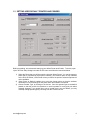
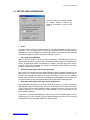
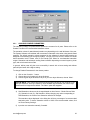
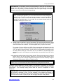
Z Corp. System Software
April 2002
Z Corporation System Software
Version 5.2.55
© 2002 Z Corporation
TABLE OF CONTENTS
1
OVERVIEW..............................................................................................................................3
1.1
COMPUTER SYSTEM REQUIREMENTS................................................................................. 3
1.1.1
ZTM400 System ...................................................................................................... 3
1.1.2
Z406 System ......................................................................................................... 4
1.1.3
Z810 System ......................................................................................................... 4
1.2
INSTALLING THE Z CORP. SYSTEM SOFTWARE ................................................................... 5
1.3
SETTING USER DEFAULT PRINTER AND POWDER ............................................................... 6
1.4
SETTING USER PREFERENCES .......................................................................................... 7
1.5
Z CORP. SYSTEM SOFTWARE MAIN WINDOW .................................................................... 8
1.6
THE SYSTEM SOFTWARE TOOLBAR ................................................................................... 9
2
SETTING UP THE BUILD......................................................................................................10
2.1
OPENING A FILE ............................................................................................................. 10
2.2
NAVIGATING THROUGH THE BUILD AREA .......................................................................... 12
2.2.1
Viewing Cross Sections of the Build.................................................................... 12
2.3
TRANSFORMING THE PART .............................................................................................. 13
2.3.1
Part Selection ...................................................................................................... 13
2.3.2
Copy and Paste ................................................................................................... 14
2.3.3
Bleed Compensation ........................................................................................... 14
2.3.4
Translate Parts .................................................................................................... 16
2.3.5
Rotate Parts......................................................................................................... 16
2.3.6
Mirror Parts .......................................................................................................... 17
2.3.7
Scale Parts .......................................................................................................... 17
2.3.8
Justify Parts ......................................................................................................... 17
2.3.9
Color Parts........................................................................................................... 19
2.3.10
Anisotropic Scaling .............................................................................................. 19
2.4
OBTAINING INFORMATION ABOUT THE BUILD .................................................................... 20
2.4.1
Print Time Estimator ............................................................................................ 20
2.4.2
Part Statistics....................................................................................................... 20
2.4.3
Collision Detection............................................................................................... 20
2.5
3D PRINT SETUP ............................................................................................................ 21
2.5.1
Changing Powder Parameters ............................................................................ 22
2.6
SAVING YOUR WORK ...................................................................................................... 24
2.7
EXPORTING PLY ............................................................................................................. 24
3
COMMUNICATING WITH THE 3D PRINTER ......................................................................25
3.1
3.2
3.3
3.4
3.5
3.6
4
SERVICE MENU .............................................................................................................. 25
Z406 SYSTEM SERVICE MENU ........................................................................................ 26
Z810 SYSTEM SERVICE MENU ........................................................................................ 27
PRINTER STATUS............................................................................................................ 28
PRINT TIME DELAYER ..................................................................................................... 29
LOGGING FILES .............................................................................................................. 30
INDEX ....................................................................................................................................31
[email protected]
2
Z Corp. System Software
1
OVERVIEW
The Z Corporation (Z Corp.) System Software is a Windows-based program that allows the user
to manipulate file data to print on any Z Corp. 3D Printer. This manual is separated into three
sections – overview, setting up the build, and communicating with your 3D Printer.
1.1 COMPUTER SYSTEM REQUIREMENTS
1.1.1
ZTM400 SYSTEM
Minimum System Requirements
•
Microsoft Windows* 95™ or 98™ operating system
•
Personal computer using a 300
MHz Pentium chip or higher
•
64 MB of RAM
•
16-bit color (or better)
•
800 x 600 pixels (or better)
•
2MB graphics card (or better)
PLEASE NOTE: Even if your system has
the capability to run the System Software, it
may not be properly configured. To ensure
that your computer is ready, select on the
desktop where there is not an icon with the
right mouse button. Select Properties, and
then select Settings. Make sure that 16-bit
color or higher is selected.
Recommended System
•
Microsoft Windows1 NT 4.0, or Windows 2000 Professional operating system
•
Personal computer using a 400 MHz Pentium II chip or higher
•
128 MB of RAM
•
16-bit color (or better)
•
1024 X 768 pixels (or better)
•
Graphics card accelerated for OpenGL
•
Virtual Memory of 500 MB
* Microsoft Windows is a trademark of Microsoft Corporation
www.zcorp-users.com
3
1.1.2
Z406 SYSTEM
Minimum System Requirements
•
Microsoft Windows NT 4.0, or
Windows
2000
Professional
operating system
•
Personal computer using a 300
MHz Pentium chip or higher
•
256 MB of RAM
•
16-bit color
•
800 x 600 pixels
•
4MB graphics card
Recommended System
1.1.3
PLEASE NOTE:
Even if your
computer system has the capability
to run the System Software, it may
not be properly configured. To
ensure that your computer is ready,
select on the desktop where there
is not an icon with the right mouse
button. Select Properties, and then
select Settings. Make sure that 16bit color or higher is selected.
•
Microsoft Windows NT 4.0 or Windows 2000 Professional operating system
•
Personal computer using a 850 MHz Pentium III chip, AMD Athlon, or better
•
512 MB of RAM or more
•
True Color Graphics
•
1024 X 768 pixels, or better
•
Graphics card accelerated for OpenGL
•
Virtual Memory of 1 GB
Z810 SYSTEM
Minimum System Requirements
•
Microsoft Windows NT 4.0, or
Windows
2000
Professional
operating system
•
Personal computer using a 1 GHz
Pentium chip or higher
•
1 GB of RAM
•
True Color Graphics
•
1024 X 768 pixels, or better
•
Graphics card accelerated for
OpenGL
•
Virtual Memory of 1 GB
PLEASE NOTE:
Even if your
computer system has the capability
to run the System Software, it may
not be properly configured. To
ensure that your computer is ready,
select on the desktop where there
is not an icon with the right mouse
button. Select Properties, and then
select Settings. Make sure that 16bit color or higher is selected.
Recommended System
The system requirements may involve a higher performance computer based on file size
and type. For more information, please contact the Z Corporation Service Department at
(781)852-5050, (877)88-ZCORP, or via email at [email protected].
[email protected]
4
Z Corp. System Software
1.2 INSTALLING THE Z CORP. SYSTEM SOFTWARE
1. Close all open applications on your computer, make sure Windows NT 4.0, or 2000
Professional Operating System is running and insert the Z Corp. System Software CD into
your CD-ROM drive.
2. If the installer does not start automatically, double-click on your CD-ROM drive and then
double-click on the ‘Setup.exe’ icon. This will start the setup sequence.
3. Read the licensing agreement carefully.
4. Select destination directory. The program will prompt you for a selection and will offer
C:\Program Files\ZCorp System Software as the default directory.
Choose your installation preference: typical (recommended), compact or custom. Once you have
made your selection, it may take several minutes to install the program. When complete, you will
be returned to your main window. If you encounter any problems during installation, please
contact the Z Corporation Service Department at (781) 852-5050, (877) 88-ZCORP, or via email
at [email protected]
WARNING: To avoid problems that may occur during printing, ensure that all screen savers and your
power management software are turned off on the computer driving the Z Corp 3D Printer. Most
screen savers and power management software can be turned off in the main Windows screen
settings. For additional instructions on how to disable your hardware and software power management,
please consult your computer hardware owner’s manual.
www.zcorp-users.com
5
1.3 SETTING USER DEFAULT PRINTER AND POWDER
Before proceeding, we recommend setting up your default Printer and Powder. To do this, open
up the ‘3D Print Setup’ dialog box under the File menu and follow the instructions below.
1) Select the Printer that you will be using by choosing ‘Select Printer’. You may choose any
printer that is connected by serial port or network. (The network option is only available
on the Z810 3D Printer.) If the Printer is busy or offline, the option to select this printer will
not be available.
2) ‘Save Printer as Default’ enables you to save the chosen printer so that the software
remembers to use the settings for this printer when the software is reopened.
3) Choose ‘Powder Type’ by clicking on the list box. Save this powder type as the default
powder so that the printer will remember to use this powder for every print job unless
manually changed. If you would like to use a powder that is not the default, you may
manually change powder type by choosing from the ‘Powder’ list box.
[email protected]
6
Z Corp. System Software
1.4 SETTING USER PREFERENCES
You may change the default settings
for several software features by
selecting ‘Preferences’ from the Edit
menu.
•
Units.
You may choose to have the measurements for your parts displayed in either inches or
millimeters. This will change the way that part dimensions and layer thickness are
displayed, but it will not change the underlying dimensions on the part. You will still need
to choose the proper units when opening or importing a new file.
•
Save slice data in ZBD files.
When a build file (ZBD) is saved, the slice information is discarded and the part is
resliced when the file is reopened. This is generally the best strategy for saving files; the
file size is significantly smaller, and because it is smaller, it will take less time to reopen.
However, once the file is opened, you will have to wait while the file reslices. If you wish
to save slice data, check this box.
•
Orient imported parts for the fastest print times.
When this box is checked, parts are always rotated so that the smallest dimension of the
part occurs in the Z direction. Since build times are largely determined by the height of
the part, this arrangement produces the fastest build times. But if you are importing
several parts that need to be placed in a predetermined arrangement to each other, you
can uncheck this box and prevent the software from automatically rotating the part.
•
Offer fast rendering for parts larger than 100,000 facets.
Large parts with many facets can be slow to draw on the screen. It is often convenient to
draw the parts using "Fast Rendering," which can be selected from the View menu. When
a file is larger than a certain threshold, before drawing the part for the first time, the
software will ask you if you prefer to use fast rendering. You can still choose to use
photo-realistic rendering.
If you have a very fast video display you may want to set the threshold higher, or even
uncheck the box. If your computer is slow to draw and refresh the screen, you can set the
threshold lower. Recommended threshold is 100,000 facets.
www.zcorp-users.com
7
•
Warn if entity is outside the build box.
If your part is outside the build area, the boundary surrounding the part will be red. The
software will also show a dialog box reminding you that your part is outside the printable
area. You may choose not to receive the warning by turning off this feature.
1.5 Z CORP. SYSTEM SOFTWARE MAIN WINDOW
Task Bar
Top View
Cross-Sectional View
Front View
Layer Count
Height from
base of
Build Box
Figure 1: The Main System Software Window
The System Software provides three views of the build in the Main Window.
•
•
•
The top view presents the view of the build in the x-y plane from the top.
The front view presents the view of the build in the x-z plane from the front of the build
area. The horizontal yellow line marks the cross-section being displayed in the crosssectional view.
The cross-sectional view displays the layers that the 3D Printer will print.
The window views can be resized for user convenience. To resize a window, place the curser
over the border between views, left-click on the border and drag to create your preferred window
size.
[email protected]
8
Z Corp. System Software
1.6
THE SYSTEM SOFTWARE TOOLBAR
Open
3D Print
Save
Mirror
Translate
Cut
Import
New
Rotate
Copy
3D Print Setup
Paste
Scale
Ten
Layers
Down
One
Layer Up
Justify
Ten
Layers Up
Select ion
List
Help
One Layer
Down
Figure 2:The System Software Toolbar
www.zcorp-users.com
9
2 SETTING UP THE BUILD
2.1 OPENING A FILE
When you initially open the Z Corp. System
Software, you will be presented with an Open
dialog box. Select the file you wish to open. You
may open zbd, stl, bld, ply, zcp, sfx, zec, or wrl
files. Keep in mind the available print areas of
the printer. Here are the following print areas:
Z400 3D Printer - 8 x 10 x 8 inches (200 x 250 x
200 mm.)
Z406 3D Printer - 8 x 10 x 8 inches (200 x 250 x
200 mm.)
Z810 3D Printer – 20 x 24 x 16 inches (500 x
600 x 400 mm.)
File Formats:
zbd files are build files created by the Z Corp.
System Software.
stl files are monochrome 3D model files
exported by several 3D CAD packages.
zcp files are Z Corporation color files.
ply files are color 3D model files exported by
several 3D CAD packages.
zec files are files created by the previous
version of the Z402C System Software.
bld files are build files created by the previous
version of the Z402 System Software.
[email protected]
sfx files are color 3D model files exported by
SolidView/Pro.
wrl (also known as VRML) files are color
files that are exported by many 3D CAD
packages.
10
Z Corp. System Software
When importing WRL (VRML) files you will be
asked to input mesh resolution and texture
threshold settings.
Mesh resolution is the number of facets in a
graphic primitive. A graphic primitive is
composed of elements that are made up of
cones, cylinders, and spheres as opposed to
triangles. The default is set at ‘40’. Setting the
number higher will increase the number of
facets making your file larger; lowering this
number will reduce the number of facets.
Texture threshold pertains to scan data, FEA
files and other files that contain texture maps. A
value of ‘0’ will render every color. Thus,
producing a large file. Increasing the number will
produce coarser rendering.
After the software has read the file, it will ask
you to choose units. A dialog box will prompt
you to choose units (inches, millimeters,
centimeters, or meters.) The System Software
will select as a default the largest unit that will fit
the part into the print area. VRML files will
always import in meters. You may also select
the powder type.
After you select the units, the System Software
will place the object into the build area in the
way that will minimize print time if you have
chosen this option under the ‘Preferences’
menu.
You may import multiple files into a single
build—each subsequent file will be placed within
the build area such that the objects will not
overlap. To insert additional files, choose
‘Import’ under the File menu. You may import
stl, ply, zcp, sfx, or wrl files.
If the model has many facets, the fast rendering
option will be offered if you have selected this
option under the ‘Preferences’ menu. This may
also be selected later under the ‘View’ menu.
www.zcorp-users.com
11
If the imported file is rendered dark and the
slices are not visible in the cross sectional view,
the back facets of the file are showing. The part
will not print properly in this orientation. To
correct the file, select part and invert all normals.
This feature is found under the ‘Edit’ menu.
Normals Inverted
Normals Corrected
2.2 NAVIGATING THROUGH THE BUILD AREA
2.2.1
VIEWING CROSS SECTIONS OF THE BUILD
The System Software offers you several ways to view cross sections:
To do this:
Menu Command
Toolbar
Keyboard Shortcut
Move up one level
Select ‘One Layer Up’
from the View menu
‘a’
Move down one
level
Select ‘One Layer Down’
from the View menu
‘z’
Move up ten levels
Select ‘Ten Layers Up’
from the View menu
Shift ‘a’
Move down ten
levels
Select ‘Ten Layers Down’
from the View menu
Shift ‘z’
TECHNICAL TIPS….
When setting up your build area with multiple parts, place larger, bulkier
parts towards the bottom of the build box.
[email protected]
12
Z Corp. System Software
2.3 TRANSFORMING THE PART
2.3.1
PART SELECTION
First select your part(s). To select parts within the build area click on the part with the left mouse
button. An yellow rectangle will appear around the part. To select multiple parts, hold down the
Shift key and select the parts you wish to modify. To de-select a single part, hold down the Shift
key and click on the image of the part. To de-select all parts, click on an open area.
You may also select parts by using the ‘Entity
Selection’ option under the Edit menu. There
is also an icon on the toolbar for this function.
Click on the part you wish to select. To
choose multiple parts, hold the Control
(CTRL) key and click on the additional parts.
•
Once imported or opened, parts can be
copied, translated, rotated, scaled, mirrored,
justified, and colored within the print area.
These options are available under the Edit
and Transform menus. They are also
available through a pop-up dialog box when
you right click on any part of the build box.
•
Choosing the ‘Undo’ option under the Edit
menu will reverse the previous action made
under the Transform menu. This means that
any feature under the Transform menu can
be reversed. The copy and color feature
under the Edit menu cannot be reversed.
Pop-Up Menu available when Right-Clicking on
the mouse.
www.zcorp-users.com
13
2.3.2
2.3.3
•
You may make additional copies of your part
by selecting the part, then choosing the
‘Copy’ option under the Edit menu or clicking
Control (CTRL) C, and then paste the file into
the build by choosing the paste option under
the Edit menu or pressing Control (CTRL) V.
The software will allow for copying and
pasting between different builds.
•
Any part copied is kept on the clipboard until
the clipboard is emptied. If you have copied
and stored a large part or several parts on
the clipboard, you may empty the clipboard
by selecting the ‘Empty Clipboard’ option
under the Edit menu. Emptying the clipboard
will reduce the amount of memory used.
•
To delete any unwanted parts, select the part
and choose the Delete option under the Edit
menu or click on Delete on the keyboard.
•
Binder printed on powder will tend to spread
slightly, causing surfaces of a part to migrate
outward. To compensate for “bleeding,” it is
necessary to perform bleed compensation on
the part, to shave off a small amount of
thickness from all surfaces.
The Z Corp. System Software allows you to
perform this function. Choose the ‘Bleed
Compensation’ option under the Edit menu.
COPY AND PASTE
BLEED COMPENSATION
•
•
•
The dialog box will detail the printer and
material type. To change printer or material
type, go to the 3D Print Setup. For more
information, see Section 1.3, Setting User
Default Printer and Powder.
The Z Corp. System Software provides
recommended values for x-, y-, and z-axes.
You may override these values by typing in
new numbers. To return to recommended
values, click ‘Reset’.
PLEASE NOTE: The values will differ
according to printer and material type.
[email protected]
14
Z Corp. System Software
•
To enable bleed compensation before
printing, click on the bleed compensation
option, located in the Printing Options dialog
box.
PLEASE NOTE: The Bleed Compensation
option will remain enabled until you
disable it by unclicking the Bleed
Compensation option.
•
The software allows you to transform the part
individually or as a group. When transformed
individually, the center of transformation is
located in the middle of the part. When
transformed as a group, the center of
transformation is located in the middle of the
group.
•
The group function is useful if you would like
to keep a group of parts oriented relative to
each other.
Here is an illustration to help clarify the
differences between individual and group
transformations.
In the picture to the left, there are two parts in the
print area.
If both parts are selected and the ‘Rotate’ option
is chosen, the parts will rotate and re-orient
themselves relative to their individual centers, as
can be seen in the picture.
www.zcorp-users.com
15
If both parts are selected, and the ‘Rotate Group’
option is chosen, the parts will rotate and reorient themselves relative to the center of the
group as can be seen in the picture.
2.3.4
TRANSLATE PARTS
• To translate or move your parts within the build
area: Select parts within the print area, and
move with the mouse. You may move the
object more precisely by choosing ‘Translate’
from the Transform menu.
2.3.5
ROTATE PARTS
• To rotate a part, select the part and choose
‘Rotate’ from the Transform menu. In the
dialog box, specify the plane and degree of
rotation.
• To keep a group of parts in the same
relative orientation, rotate as a group. Select
the parts, and choose ‘Rotate Group’.
• You may also rotate using ‘Rotate in Active
View’. Determine the view you would like to
rotate the part in (top view, or front view).
Then choose the part in that view. The
yellow box surrounding the part will be
highlighted in a brighter yellow box in the
view that you have chosen. Then choose
one of the options under the ‘Rotate in
Active View’ menu.
[email protected]
16
Z Corp. System Software
2.3.6
MIRROR PARTS
Original File
• Mirroring a part or group of parts allows you
to inverse the orientation of the part features
in the x, y, or z axis. The software does this
by placing a plane in the center of the part in
the x, y, and z axis. When you choose to
mirror a part in a certain axis, the software
will invert the part within that axis.
Copy and
Mirrored Hand in
the X-Axis
• To mirror a part, select the part and
select “Mirror” from the Transform
menu. The software will not create a
separate part. It will take the part
selected and invert the orientation for
this part.
• You may also mirror a group of parts
by selecting the parts, and choosing
‘Mirror Group’.
2.3.7
SCALE PARTS
• To scale the part, select the part and choose
‘Scale’ from the Transform menu. In the
dialog box, you are given several options.
You may scale the object relative to the
dimensions in the imported file and the units
you initially selected by entering a
percentage in the ‘Relative’ box. Remember
to limit your selection to the maximum limits
of the build area.
• You may also scale a group of parts by
selecting the parts, and choosing ‘Scale
Group’. Only the relative option is available
when scaling a group of parts.
2.3.8
JUSTIFY PARTS
• To justify the part, select the part and
choose ‘Justify’ from the Transform menu.
You may justify the part to the center, left,
right, front, back or bottom of the build box.
Justifying the part lets the software move the
part to the edge of the print area optimizing
your build area.
• You may also choose to justify a group of
parts.
www.zcorp-users.com
17
PLEASE NOTE: In the process of
changing the location or orientation of a
part, you may find that parts overlap in
the build box or exceed the boundaries of
the build box.
If parts exceed the
boundaries of the build box, the System
Software will alert you with an error
message and the part in question will be
outlined in red unless this feature has
been disabled under Preferences. To fix
the problem, select the part and either
move it within the build box or use the
‘Justify’ feature to bring the part
completely within the build box. You will
need to rescale your part if it does not fit
into the build box after justification.
If parts overlap with each other in the
build box, you will NOT receive an error
message unless you choose to run the
‘Collision Detection’ feature under the
View menu. The feature will take a few
minutes to process the build. A dialog
box will appear when the software
detects a part overlap. It will let you know
if there was a collision and where the
collision was detected. After fixing the
part overlap, carefully inspect the build
box by checking the layers of the build.
Press the A or Z key to move through
each layer. Then rerun the Collision
Detection function.
[email protected]
18
Z Corp. System Software
2.3.9
COLOR PARTS
The color option is only available when the
System Software is connected to a Z Corp.
Color Printer – Z402C, Z406, or Z810 3D
Printer.
You may color your monochrome stl part.
1. Select the part.
2. Choose ‘Color’ option under the Edit menu.
3. Pick a color from the color pallet or choose
to define a custom color.
4. Click ‘OK’.
The part will be colored by an outer shell as with
all Z Corp. color parts.
PLEASE NOTE: Only monochrome
files (STL) may be colored. If you
select a color part, the software will
remind you that the color feature is
only available for monochrome files.
2.3.10 ANISOTROPIC SCALING
• Anisotropic scaling factors may vary
for different types of geometries and
powders. The software allows you to
set anisotropic scaling factors for the
build or for a specific part.
• To change anisotropic scaling factors
to affect the entire build, change the
powder parameters under 3D Print
Setup. For more information, see the
User Manual for your printer.
PLEASE NOTE: Before changing anisotropic scaling factors for specific parts, make
sure anisotropic scaling factors have been
set for the entire build.
www.zcorp-users.com
• In some circumstances, you may need
to change your scaling factors for an
individual part. To change anisotropic
scaling factors for a specified part,
choose the part and select the
‘Anisotropic Scaling’ option under the
Transform menu. Enter your custom
anisotropic scaling factors for the x, y,
and z axis. Click ‘OK’. These anisotropic scaling factors will only affect the
selected part(s).
19
2.4 OBTAINING INFORMATION ABOUT THE BUILD
The System Software allows you to estimate the time required to print your build in color and
monochrome mode, the number of pixels the part will use and other statistics.
2.4.1
2.4.2
2.4.3
PRINT TIME ESTIMATOR
•
Select ‘Print Time Estimator’ from the File
Menu. The System Software will return a
dialog box with the estimated build time.
For the Z400 Printer, only the monochrome
build time will be available.
•
To calculate the surface area and volume
of the build, select ‘Calculate Part
Statistics’ from the View menu.
•
Collision detection will search for parts that
are placed too close together or overlap.
When parts are placed too close together,
the sides of the parts may adhere to each
other. It will take the software a few
minutes to search through the layers. Once
a collision has been detected, a dialog box
will appear regarding which layer the
collision was detected.
PART STATISTICS
COLLISION DETECTION
PLEASE NOTE: Collision Detection
will only report the first collision
detected. Please make sure to check
layers or run Collision Detection again
after fixing the problem.
[email protected]
20
Z Corp. System Software
2.5 3D PRINT SETUP
The ‘3D Print Setup’ dialog box allows you to select a printer, choose a powder type, and
change powder parameters. This dialog box is found under the ‘File’ menu. It is also located
as an icon on your task bar. IT IS STRONGLY RECOMMENDED THAT THE 3D PRINT
SETUP PARAMETERS BE CHECKED BEFORE PRINTING A BUILD.
Information regarding setting up your printer and powder type as defaults can be found in
Section 1.3, Setting User Default Printer and Powder.
www.zcorp-users.com
21
2.5.1
CHANGING POWDER PARAMETERS
The saturation settings for plaster-based powder are constant for all parts. Please refer to the
Powder Fact Sheet for recommended saturation values.
The saturation values for starch-based powders vary depending on the wall thickness of the part.
The System Software will calculate and recommend a saturation value when using starch-based
powders. The default saturation values suggested by the software for starch-based powder are
designed to successfully print a majority of parts. You may, from time to time, choose to override
these saturation levels. Please refer to the Powder Fact Sheet for recommended saturation
ranges. Saturation and anisotropic scaling factors will differ depending on material system, printer
type, and color/monochrome mode.
In general, bulkier parts will print more successfully in starch with a lower setting and delicate
parts will print better with a higher setting.
To change Powder Parameters for the chosen powder:
1) Click on the ‘Override…’ button.
2) Choose the unit of measure for layer thickness.
3) Choose a given layer thickness or to put in your own layer thickness, choose ‘Other’.
PLEASE NOTE: Your custom layer thickness will be saved as long as you continue to use
this layer thickness. Once you choose to use a standard layer thickness, the custom layer
thickness will no longer be the default. The ‘Other’ option will reappear.
4) Shell Saturation values may be changed based on three factors – Binder/Volume Ratio
(%), Saturation Level (%), and Saturation. When changing any value corresponding to
Shell Saturation, the relative Core Saturation will also be changed.
The saturation values displayed in the dialog box will be a percentage of a recommended
saturation value. To set the saturation values to 100% of the recommended values, click
on ‘Reset Factory Settings’.
5) Input the core saturation manually if needed.
[email protected]
22
Z Corp. System Software
PLEASE NOTE: Z Corporation provides recommendations for shell and core saturation for
powder types. This can be found on the Powder Fact Sheet provided with your case of
powder. You may choose to increase saturation values for higher strength or decrease
saturation values due to difficulties with depowdering.
PLEASE NOTE: If printing with starch-based powders - When pressing “3D
Print”, a warning will appear if you do not check the 3D Print Setup dialog box
before printing. It will let you know how the saturation is currently set before
printing. If you choose to override the saturation values, click ‘No’ and edit the
settings as described above. If you would like to continue printing with the
saturation values given, click on ‘Yes’.
6) Default values are defined in terms of percentage. The recommended saturation values
will always be at 100%. You may choose to set a default percentage value for saturation
values and save these as default. This will be applied when you press ‘Use Default’.
For example, if you would like to use 90% of the recommended shell saturation value for
every build, choose to override the current settings and type in the desired value. Click
‘OK’. Then select ‘Save as Default’. This will save your shell saturation percentage value
as default. When setting up a new build, click on ‘Use Default’. The percentage value
saved will be used. In this example, the shell saturation value would be set at 90% of the
default.
Input anisotropic scaling factors for the chosen powder. These values may then be saved as
default values in the ‘3D Print Setup’ dialog box. This scaling will affect all parts in the
build. You may choose to assign anisotropic scaling factors for each model by using the
‘Anisotropic Scaling’ option under the Transform menu.
PLEASE NOTE: The build anisotropic scaling factors will override any factors set for each
model. Thus, it is recommended that the build anisotropic scaling factors be set first.
Anisotropic scaling operates as a simple multiplier. The shrinkage or expansion you experience
may differ from the norm because of humidity and temperature variations between operating
environments. The anisotropic scaling factors allow the printer to compensate for these
differences.
PLEASE NOTE: When anisotropic scaling factors are applied to a build, the physical part
will increase or decrease in size. The part rendered on the software will change in
appearance with the anisotropic change but the dimensional values will remain the same.
You may need to rescale or justify the part after changing anisotropic scaling factors.
www.zcorp-users.com
23
2.6 SAVING YOUR WORK
After you have imported the files, oriented the parts and set up your build to print, save your work
by selecting ‘Save As’ from the File menu. After you choose a name for your build, select ‘Save’
and your work will be saved as a *.zbd file. A build file contains all of the modifications that you
have made to the parts and the settings you have selected for the build.
If you reopen and work on an existing build file, you can save your changes to the *.zbd file by
either selecting ‘Save’ from the File menu or choosing the save icon from the tool bar.
2.7 EXPORTING PLY
The System Software allows you to export your model from the build if needed so that you may
alter your part. To export a part, choose the part. Then choose the ‘Export PLY’ option under the
File menu.
[email protected]
24
Z Corp. System Software
3 COMMUNICATING WITH THE 3D PRINTER
The System Software communicates with the Printer in several ways. It communicates with the
Printer during routine Service procedures, and allows the user to receive Printer Status.
3.1
SERVICE MENU
The System Software allows you to draw information from the Z
Corporation 3D Printer and activate some printer functions. The
basic Service menu is available when any Z Corp. Printer is
communicating with the software. For more information about how
the Service functions work, see the User Manual.
•
Get Piston Levels. (Shortcut Key: F1) To check the available powder in the Feed
Piston and the remaining room in the Build Box, Select ‘Get Piston Levels’. This
option also communicates firmware version.
•
Squirt Squeegee. (Shortcut Key: F2) This feature allows you to rinse the
squeegees in the Service Station or test the alignment of the Squeegee Squirters.
This feature applies to the Z406 and Z810 Printers.
•
Service Print Head. (Shortcut Key: F3) This feature allows you to service the print
head if it is not printing well.
•
Toggle Roller on/off. (Shortcut Key: F4) This allows you to activate the roller
independently for easy cleaning.
•
Toggle Vacuum hi/low. (Shortcut Key: F5) This feature applies to the Z402 and
Z402C 3D Printers.
•
Change Print Head. This feature allows you to change the print heads, as described
in detail in the User Manual.
•
Flush Binder. This feature allows you to cycle fluid through the plumbing system,
which is useful in changing the binder color or binder type, as described in detail in
the User Manual.
•
Report Capabilities. This feature allows you to view the capabilities of the Z
Corporation Printer connected to your computer. It reports the build size, and print
modes.
•
Report Print Head Usage. This feature calculates the accumulated pixel usage for
all print heads.
•
Stripe Test. This feature allows you to test the printing status of your print heads.
This feature is available on the Z406 and Z810 Printers.
•
Upload New Firmware and Upload New Printer Configuration. These features
allow you to upgrade the firmware that is in your 3D Printer. The Service Department
will provide you with required upgrades and instructions. Use this option only under
the guidance of the Service Department.
www.zcorp-users.com
25
In addition to the basic Service menu, each of the Z406 and Z810 Printers have
specific service menus.
3.2 Z406 SYSTEM SERVICE MENU
When connected to a Z406 3D Printer, the 406Service menu will be an
option.
•
Purge Print Heads. Use this feature after changing the print heads and printing the
alignment test. This runs binder through the print head, replacing the HP ink with binder
as described in the User Manual.
•
Alignment. This feature is used to align the print heads after changing them as described
in detail in the User Manual.
•
Color Alignment. This feature is used to align the color print heads after the standard
alignment as described in detail in the User Manual.
•
Change Binder Supply. This feature allows you to change between color and
monochrome binder systems.
•
Unpark. This feature allows you to unpark the carriage to allow for cleaning the Service
Station.
•
Bleed Air. This function allows you to remove air from the fluid system. This feature is
only used when air has entered your fluid system due to binder shortage when printing.
Use this feature only with the guidance of the Z Corporation Service Department or
authorized Z Corporation service provider.
•
Print Head Report. This feature allows you to view the number of pixels printed,
temperature levels, and flow rates of the current print heads.
•
View Log. This feature allows you to view the printer log, which records historical printer
performance.
•
Edit .INI File, Send File and Receive File. These features are used during diagnosis.
They should be used under the instruction of the Z Corporation Service Department or
authorized Service representative.
[email protected]
26
Z Corp. System Software
3.3 Z810 SYSTEM SERVICE MENU
When connected to a Z810 3D Printer, the 810Service menu
will be an option.
•
Purge Print Heads. Use this feature after changing the print heads and printing the
alignment test. This runs binder through the print head, replacing the HP ink with
binder as described in the User Manual.
•
Alignment. This feature is used to align the print heads after changing them as
described in detail in the User Manual.
•
Change Binder Supply. This feature allows you to change between color and
monochrome binder systems.
•
Unpark. This feature allows you to unpark the carriage to allow for cleaning the
Service Station.
•
Bleed Air. This function allows you to remove air from the fluid system. This feature is
only used when air has entered your fluid system due to binder shortage when
printing. Use this feature only with the guidance of the Z Corporation Service
Department or authorized Z Corporation service provider.
•
Print Head Report. This feature allows you to view the number of pixels printed,
temperature levels, and flow rates of the current print heads.
•
View Log. This feature allows you to view the printer log, which records historical
printer performance.
•
Edit .INI File, Send File and Receive File. These features are used during diagnosis. They
should be used under the instruction of the Z Corporation Service Department or authorized
Service representative.
•
Fill Bed. Prepares the build to print by filling the bed with powder. It is the equivalent
of pushing the ‘Fill Bed’ option on the printer control panel.
•
Empty Overflow. This feature allows you to empty the overflow bin before each
build.
•
Spit on Deck. This feature allows you to test the print quality of your print heads.
This feature is used after changing print heads. But can also be used when your print
heads have reached a high pixel count.
www.zcorp-users.com
27
3.4 PRINTER STATUS
When the Printer is getting ready to print, it will conduct a system status check of the Printer. For
example, with the Z406 and the Z810 Printers, if you have a color model in the build but are in
monochrome mode, the System Software will remind you that you are in monochrome mode and ask
if you would like to continue printing the part.
On all Z Corp. Printers, the System Software will warn you if you do not have enough materials to
print your model.
During printing, the System Software will update you on the status of your print job.
[email protected]
28
Z Corp. System Software
3.5 PRINT TIME DELAYER
The System Software also allows you to print your build at a later time. In instances where the set up
time in the build area is specific (as in the case of starch builds), you may choose to use the print time
delayer option in order to have the part finish at a certain time. For instance, if you would like to print
a five-hour starch part to finish at 8:00 AM, you would use the print time delayer to begin printing the
part beginning at 3:00 AM. Using the print time delayer option prevents parts from sitting in the build
area for too long. This option can be enabled before printing in the 3D Print Options dialog box.
You will then be asked to input how many hours and/or minutes to delay your build. You may also
choose to use the arrows to increase or decrease values. The estimated finish time will change as
you input values for the hours and minutes.
www.zcorp-users.com
29
3.6 LOGGING FILES
In addition to communicating with the Printer, the System Software also records print information from
the Printer.
When the option to log files is checked off at the start of the build, the System Software will log
information regarding each build. The log files can be found in the directory “C:\ZCorp Printer
Records\Print Logs”. They are tab-delimited files for easy import into a spreadsheet. When the print
heads are changed, the line ” Print head changed!” is inserted. If this file becomes too large, either
delete it or rename it; the software will automatically start a new one. There is also an html file letting
you know the status of your build. This file can be accessed through the network by sharing this Print
Logs folder. To share this folder, right click on the folder, select properties and select the ‘Sharing’
tab. Choose to share the folder.
Below is a description of the data found in the log file.
Build Date:
Time:
Job Pixels:
The desktop computer’s date when the build was started.
Time to complete printing in minutes.
Total number of pixels fired during the job (sum of all print heads).
Note: pixels are not logged for print head purging between jobs.
Fed:
Approximately how much binder was fed during the job, in milliliters.
Prime
Does not apply to the Z406 or Z810 Systems, only the Z400, Z402, and Z402C Systems.
Dsize
Does not apply to the Z406 or Z810 Systems, only the Z400, Z402, and Z402C Systems.
DSDEV
Does not apply to the Z406 or Z810 Systems, only the Z400, Z402, and Z402C Systems.
Error
If the job was terminated with an error code, it will be recorded here.
Max
The maximum head temperature during the build.
Min
The minimum head temperature during the build
Pre
Does not apply to the Z406 or Z810 Systems, only the Z400, Z402, and Z402C Systems.
Vol
Part volume
Area
Total printed area
Shell
Shell saturation
Core
Core saturation
Thickness
Layer thickness
Name
File name for the job
Version
Software Version
Powder Type
Powder System
Color Mode
Color or Monochrome Mode
BleedComp
Bleed Compensation On or Off
Estimated Time Estimated print time for build
Estimated Pixels Estimated pixel usage for build
Head Report
The accumulated number of pixels printed per print head.
[email protected]
30
Z Corp. System Software
4
INDEX
3
3D Print Setup
22
A
Anisotropic Scaling
For Specified Part
Anisotropic Scaling Values
20
24
B
BLD Build Files
Bleed Compensation
10
14
C
Changing Powder Parameters
Collision Detection
Color
Computer System Requirements
Z400 System
Z406 System
Z810 System
Copy
Empty Clipboard
From Different Build
Cross-Sectional View
Main Window
Viewing Layers
STL Files
VRML Files
WRL Files
ZBD Files
ZCP Files
ZEC Files
Fill Bed
10
10
10
10
10
10
28
I
Importing a File
Installation
11
5
J
Justify
23
19, 21
19
3
3
3
4
14
14
14
8
12
18
L
Layer Thickness
Logging Files
23
31
M
Main Window
Cross-Sectional View
Front View
Resize
Top View
Mirror
Group
8
8
8
8
8
17
D
Delete
N
14
Normals
Invert All
E
Empty Clipboard
Empty Overflow
Entity Selection
Export PLY
14
28
13
25
12
O
Open
Files
Orient for Faster Print Time
10
7
F
Fast Rendering
Preferences
Logging
10
File Formats
BLD Files
PLY Files
SFX Files
www.zcorp-users.com
P
7
31
10
10
10
10
Part Statistics
Paste
PLY Files
Pop-Up Menu
Preferences
Fast Rendering
Orient for Faster Print Time
Save Slice Data
21
14
10
13
7
7
7
31
Units
Warn if Part is Outside of Build Box
Print Time Delayer
Print Time Estimator
Printer Status
7
8
30
21
29
R
Rotate
Group
In Active View
17
17
17
T
Time Estimator
Toolbar
Transform
Individual vs. Group
Translate
[email protected]
15
16
U
Units
User Preferences
S
Saturation Values
Plaster Powder
Restore Factory Settings
Setting Defaults
Starch-Based Powders
Saturation Values
Save
Save Powder Type as Default
Save Printer as Default
Scale
Group
Select Parts
Select Powder
Select Printer
Service Menu
Flush Binder
Prime Print Head.
Report Capabilities
Squirt Squeegee
Stripe Test
Toggle Roller on/off
Upload New Firmware
Upload New Printer Configuration
Service Menu
Change Print Head
Get Piston Levels
Toggle Vacuum
Z406 Printer
Z810 Printer
SFX Files
Slice Data
Save
Spit on Deck
STL Files
system requirements
21
9
7
7, 10
V
23
23
24
23
23
25
6, 23
6, 23
18
18
13
6
6
26
26
26
26
26
26
26
26
26
26
26
26
27
28
10
7
28
10
4
Viewing Cross Section
VRML Files
Importing
Mesh Resolution
Texture Threshold
12
10
11
11
11
W
WRL Files
10
Z
Z406 Service Menu
Alignment
Bleed Air
Change Binder Supply
Color Alignment
Print Head Report
Purge Print Heads
Unpark
View Log
Z810 Service Menu
Alignment
Bleed Air
Change Binder Supply
Empty Overflow
Fill Bed
Print Head Report
Purge Print Heads
Spit on Deck
Unpark
View Log
ZBD Build Files
ZCP Files
ZEC Files
27
27
27
27
27
27
27
27
27
28
28
28
28
28
28
28
28
28
28
28
10
10
10
32