1
ES2400 – ES2403 – ES4800 - ES6000
User's Manual
___________________________________________________________________________________________________________________________________________________
EagleSmart
ES2400, ES2403, ES4800, ES6000
USER'S MANUAL
V2.3 – August 2006
www.eagletronicchargers.com
__________________________________________________________________________________________________________________________________________________
Page 1/14
ES2400 – ES2403 – ES4800 - ES6000
User's Manual
___________________________________________________________________________________________________________________________________________________
INDEX
· 1. SAFETY INSTRUCTIONS AND WARNINGS............................................. 3
· GENERAL.................................................................................................................... 3
· SHOCK PREVENTION................................................................................................ 3
· BURN AND BODILY INJURY PREVENTION.............................................................. 4
· FIRE AND EXPLOSION PREVENTION...................................................................... 4
· ARCING AND BURNING OF CONNECTOR............................................................... 4
· MEDICAL AND FIRST AID TREATMENT................................................................... 4
· 2. DESCRIPTION OF THE CHARGER........................................................... 5
· 3. INSTALLATION OF THE CHARGER.......................................................... 5
· AC INPUT CONNECTION........................................................................................... 6
· AC INPUT VOLTAGE SETTINGS............................................................................... 6
· 4. HOW TO USE THE CHARGER................................................................... 8
· PROGRAMMATION OF THE FINISHING CHARGE TIME......................................... 8
· BATTERY CONNECTION – AUTOMATIC VOLTAGE CHECK AND AUTOSTART....9
· CHARGE OPERATION................................................................................................ 9
· OVERVOLTAGE PROTECTION............................................................................... 10
· SAFETY TIMER – EMERGENCY STOP................................................................... 10
· AUTOMATIC DATA SAVING..................................................................................... 11
· OVERCURRENT/SHORT CIRCUIT ......................................................................... 11
· SHUTDOWN ON BATTERY DISCONNECTION....................................................... 11
· MANUAL CHARGE TERMINATION.......................................................................... 12
· EQUALIZATION......................................................................................................... 12
· QUICK TEST FUNCTION.......................................................................................... 13
__________________________________________________________________________________________________________________________________________________
Page 2/14
ES2400 – ES2403 – ES4800 - ES6000
User's Manual
___________________________________________________________________________________________________________________________________________________
1. SAFETY INSTRUCTIONS AND WARNINGS
Before to start using your EagleSmart battery charger, please take the time to read these
instructions carefully.
The owner’s manual is an important part of the charger. It’s recommended to keep it in good
condition for the lifetime of the charger. It should be kept in a dry and clean place, always
available to the users.
To indicate important instructions, the following blocks are used throughout this manual.
CAUTION!
This operation can be dangerous for the user.
ATTENTION!
This operation is important for the functionality and reliability of the charger.
GENERAL
Battery charging products can cause serious injury or death, or damage to other equipment or
property, if the operator does not strictly observe all safety rules and take precautionary
actions.
Safe practices must be learned through study and training before using this equipment.
Only qualified personnel should install, use, or service this equipment.
SHOCK PREVENTION
Bare conductors, or terminals in the output circuit, or ungrounded, electrically-live
equipments can fatally shock a person. To protect against shock, have competent electrician
verify that the equipment is adequately grounded and learn what terminals and parts are
electrically HOT.
The body’s electrical resistance is decreased when wet, permitting dangerous current to flow
through the body. Do not work in damp area without being extremely careful. Stand on dry
rubber mat or dry wood and use insulating gloves when dampness or sweat cannot be
avoided. Keep clothing dry.
INSTALLATION AND GROUNDING - A power disconnect switch must be located at the
equipment. Check the data label for voltage and phase requirements. If only 3-phase power is
available, connect single-phase equipment to ONLY TWO WIRES of the 3-phase line.
DO NOT CONNECT the equipment grounding conductor to the third live wire of the 3-phase
line as this makes the equipment frame electrically HOT, which can cause a fatal shock.
If a grounding conductor is part of the power supply cable, be sure to connect it to a properly
grounded switch box or building ground. If not part of the supply cable, use a separate
grounding conductor. Don’t remove a ground prong from any plug. Use correct mating
receptacles. Check ground for electrical continuity before using equipment. The grounding
conductor must be of a size equal to or larger than the size of the line conductors.
CHARGING LEADS – Inspect leads often for damage to the insulation. Replace or repair
cracked or worn leads immediately. Use leads having sufficient capacity to carry the operating
current without overheating.
BATTERY TERMINALS – Do not touch battery terminals while equipment is operating.
__________________________________________________________________________________________________________________________________________________
Page 3/14
ES2400 – ES2403 – ES4800 - ES6000
User's Manual
___________________________________________________________________________________________________________________________________________________
SERVICE AND MAINTENANCE – Shut OFF all power at the disconnect switch or line breaker
BEFORE inspecting, adjusting, or servicing the equipment. Lock switch OPEN (or remove line
fuses) so that the power cannot be turned ON accidentally.
Disconnect power to equipment if it is to be left unattended or out of service. Disconnect
battery from charger. Keep inside parts clean and dry. Dirt and/or moisture can cause
insulation failure. This failure can result in high voltage at the charger output.
BURN AND BODILY INJURY PREVENTION
The battery produces very high currents when short circuited, and will burn the skin severely
if in contact with any metal conductor that is carrying this current.
Do not permit rings on fingers to come in contact with battery terminals or the cell connectors
on top of the battery. Battery acid is very corrosive. Alwais wear correct eye and body
protection when near batteries.
FIRE AND EXPLOSION PREVENTION
When batteries are being recharged, they generate hydrogen gas that is explosive in certain
concentrations in air (the flammability or explosive limits are 4.1% to 72% hydrogen in air). The
spark-retarding vents help slow the rate of release of hydrogen, but the escaping hydrogen
may form an explosive atmosphere around the battery if ventilation is poor.
The ventilation system should be designed to provide an adequate amount of fresh air for the
number of batteries being charged. This is essential to prevent an explosion.
Always keep sparks, flames, burning cigarettes, and other sources of ignition away from the
battery recharging area. Do not break "live" circuits at the terminals of batteries. Do not lay
tools or anything that is metallic on top of any battery.
ARCING AND BURNING OF CONNECTOR
To prevent arcing and burning of the connector contacts, be sure the charger is OFF before
connecting or disconnecting the battery. The ammeter should NOT indicate current flow.
MEDICAL AND FIRST AID TREATMENT
First aid facilities and a qualified first aid person should be available for each shift for
immediate treatment of electrical shock victims.
EMERGENCY FIRST AID: Call phisician and ambulance immediately and use First Aid
techniques recommended by the American Red Cross.
DANGER: ELECTRICAL SHOCK CAN BE FATAL.
If person is unconscious and electric shock is suspected, do not touch person if he or she is
in contact with charging equipment, battery, charging leads, or other live electrical parts.
Disconnect power at wall switch and then use First Aid.
Dry wood, wooden broom, and other insulating material can be used to move cables, if
necessary, away from person.
IF BREATHING IS DIFFICULT, give oxygen.
IF NOT BREATHING, BEGIN ARTIFICIAL BREATHING, such as mouth-to-mouth.
IF PULSE IS ABSENT, BEGIN ARTIFICIAL CIRCULATION, such as external heart massage.
In case of acid in the eyes, flush very well with clean water and obtain professional medical
attention immediately.
__________________________________________________________________________________________________________________________________________________
Page 4/14
ES2400 – ES2403 – ES4800 - ES6000
User's Manual
___________________________________________________________________________________________________________________________________________________
2.
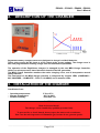
DESCRIPTION OF THE CHARGER
EagleSmart battery chargers have been designed to charge Lead-Acid batteries.
These units convert the AC input to a DC output at the correct voltage. The charge curve is
Wa, with programmable finishing charge time and automatic equalization.
The operation of the EagleSmart chargers is managed by the new MRG Charge Controller,
which is a microprocessor based electronic board of the last generation.
The MRG Charge Controller monitors the entire charging curve, and it incorporates several
safety features.
The front panel of the MRG charge controller is composed by 4 status LEDs (CHARGING –
80% CHARGED – COMPLETE – FAULT! / ALARM !) and 3 ammeter LEDs.
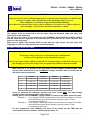
3. INSTALLATION OF THE CHARGER
Conditions of use:
•
•
•
Operating temperature:
Storage temperature:
Relative humidity:
5°C to 45°C
-20°C to 60°C
less than 75%
CAUTION!
Risk of electrical shock!
The charger can be installed by qualified personnel only.
To prevent fire or shock hazard, do not expose the unit to rain or moisture.
Don't use the unit in presence of flammable gas, because it can generate sparks.
__________________________________________________________________________________________________________________________________________________
Page 5/14
ES2400 – ES2403 – ES4800 - ES6000
User's Manual
___________________________________________________________________________________________________________________________________________________
ATTENTION!
Make sure that the unit's maximum input power (reported on the data label) is available from
your power supply, and verify that the unit's operating voltage is correct.
Allow adequate air circulation to prevent internal heat buildup.
Don't place the unit near heat sources such as radiators or air ducts, or in a place subject to
direct sunlight, excessive dust, mechanical vibration or shock.
AC INPUT CONNECTION
The charger must be connected to the AC input using an adequate cable and plug, with
disconnect switch and fuses.
The AC input wires have to be connected to the TERMINAL BLOCKS FOR AC INPUT CABLE,
that are located on the right side of the internal panel, just under the AC input contactor (see
picture on the next page).
Make sure to tighten the terminal block screws with the right torque, and pull each wire
separately in order to verify that they are mounted properly.
AC INPUT VOLTAGE SETTINGS
ATTENTION!
The proper setting of the power transformer taps is fundamental
for the correct operation of the EagleSmart chargers.
If the real AC input voltage is different than the AC nominal voltage to which the charger is set,
the charging current of the charger may be significantly different than the nominal.
•
•
•
•
With reference to the pictures in the next page, find the POWER TRANSFORMER TAPS
and the label with the list of the 5 NOMINAL voltages available, that are located on the
left side of the internal panel.
SR2400
SR2403
SR4800
SR6000
1
1x 250 VAC
3x 250 VAC
3x 500 VAC
3x 620 VAC
2
1x 240 VAC
3x 240 VAC
3x 490 VAC
3x 610 VAC
3
1x 224 VAC
3x 224 VAC
3x 480 VAC
3x 600 VAC
4
1x 208 VAC
3x 208 VAC
3x 460 VAC
3x 575 VAC
5
1x 200 VAC
3x 200 VAC
3x 440 VAC
3x 550 VAC
Using an adequate AC-voltmeter, measure the value of the REAL AC input voltage
available at the mounting location of the charger.
Identify which of the 5 NOMINAL voltage values is closest to the REAL measured value.
Example 1: for a charger ES2400 (singlephase) if the measured voltage is 212 VAC,
the transformer should be connected to the tap number 4, that
corresponds to 208 VAC.
Example 2: for a charger ES6000 (threephase) if the measured voltage is 608 VAC,
the transformer should be connected to the tap number 2, that
corresponds to 610 VAC
For the singlephase units (ES2400), the wires to be moved are the TWO that are
connected to the AC contactor, marked with the letter “A”.
__________________________________________________________________________________________________________________________________________________
Page 6/14
ES2400 – ES2403 – ES4800 - ES6000
User's Manual
___________________________________________________________________________________________________________________________________________________
•
For the threephase units (ES2403 – ES4800 – ES6000), the wires to be moved are the
THREE that are connected to the AC contactors, marked with the letters “A”, “B” and
“C”.
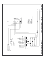
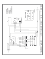
Singlephase units (ES2400)
Threephase units (ES2403 – ES4800 – ES6000)
__________________________________________________________________________________________________________________________________________________
Page 7/14
ES2400 – ES2403 – ES4800 - ES6000
User's Manual
___________________________________________________________________________________________________________________________________________________
4.
HOW TO USE THE CHARGER
PROGRAMMATION OF THE FINISHING CHARGE TIME
The programmabie finishing charge times are 2 to 12 hours in the MRG Charge Controller.
The default value (factory programmed) is 3 hours.
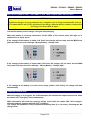
Behind the small hole located near the LED “80% CHARGED”, there is a button that is used to
program the finishing charge time. This button can be reached using a small object, like a
needle, a small screwdriver or a toothpick.
•
•
•
•
•
•
Disconnect the charger from the AC input.
Connect a battery. The four status LEDs will blink alternately.
Push the button for the programmation of the finishing
charge time to enter the programming mode. Only one
LED will blink. This LED corresponds to the finishing
charge time that was previously programmed, with
reference to the picture on the right.
Push the button again to move the blinking LED to the
desired position.
Wait for 5 seconds. The charger will return to normal
mode, and the four status LEDs will blink alternately.
Disconnect the battery.
__________________________________________________________________________________________________________________________________________________
Page 8/14
ES2400 – ES2403 – ES4800 - ES6000
User's Manual
___________________________________________________________________________________________________________________________________________________
BATTERY CONNECTION – AUTOMATIC VOLTAGE CHECK AND AUTOSTART
ATTENTION!
EagleSmart chargers are programmed to do a complete cycle of charge automatically, however
it's recommended to survey the operation of the charger when the battery remains connected to
the charger for more than 12 hours.
Connect the battery to the charger, using an adequate plug.
When the battery is correctly connected, all the LEDs of the control panel will light on in
sequence for a quick check.
If the voltage of the battery is below 1,60 V/cell, the charger will not start, and the MRG front
panel will show the error message “Wrong Battery - Voltage Low”.
If the voltage of the battery is higher than 2,50 V/cell, the charger will not start, and the MRG
front panel will show the error message “Wrong Battery - Voltage High”.
If the voltage of the battery is in the correct range [1,60 to 2,50 V/cell], the charge will start
automatically.
CHARGE OPERATION
While the charge is in progress, the 3 LED ammeter will indicate the output current level, while
the status LED “Charging” blink continuously.
When the battery will reach the gassing voltage (2,40 V/cell) the status LED “80% Charged”
will start blinking, together with the LED “Charging”.
The charge will continue for the programmed finishing time (2 to 12 hours), following the Wa
charge curve.
__________________________________________________________________________________________________________________________________________________
Page 9/14
ES2400 – ES2403 – ES4800 - ES6000
User's Manual
___________________________________________________________________________________________________________________________________________________
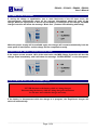
When the charge is complete, the charger switches off automatically, and the MRG front panel
will give the message “COMPLETE”:
OVERVOLTAGE PROTECTION
If, during the charge, the voltage of the battery will increase above 2,80 V/cell, the charger will
shut down automatically, and the MRG front panel will show the message “Voltage High”:
SAFETY TIMER – EMERGENCY STOP
The MRG controller includes a safety timer that shuts the charger down if the battery doesn't
reach the gassing voltage within a defined time limit. This time limit is not fixed, but it depends
on the finishing time selected by the user.
If this condition occurs, the MRG front panel shows the message “Time Error”:
The cause if this problem may be a wrong setting of the input voltage: if the input is set to a
certain value (for example: 610 V) but the real voltage is lower (for example: 575 V), the
charging current will be significantly lower than the nominal value, therefore the battery will
take too long to reach the gassing voltage.
__________________________________________________________________________________________________________________________________________________
Page 10/14
ES2400 – ES2403 – ES4800 - ES6000
User's Manual
___________________________________________________________________________________________________________________________________________________
AUTOMATIC DATA SAVING
If, during the charge or equalization, one or more black-outs of the AC input occur, the
microprocessor automatically saves all the relevant informations about the state of the
charge. While the input power is absent and the battery is connected to the charger, the MRG
Charge Controller will show the message “Black Out” (4 status LEDs blinking alternately).
When the power supply will be available again, the charger will re-start automatically from the
exact point of interruption, and the charge will be completed normally.
OVERCURRENT/SHORT CIRCUIT PROTECTION
If the output current exceeds 140% of the rated value, the MRG Charge Controller will shut the
charger down immediately, and it will show the message “OVERCURRENT” on the front panel.
SHUTDOWN ON BATTERY DISCONNECTION
CAUTION!
NEVER disconnect the battery while it's being charged.
Disconnecting the battery while it's being charged is hazardous
for the user and voids the charger warranty.
If the battery is disconnected while the charge is in progress, the EagleSmart charger will
swich off automatically.
__________________________________________________________________________________________________________________________________________________
Page 11/14
ES2400 – ES2403 – ES4800 - ES6000
User's Manual
___________________________________________________________________________________________________________________________________________________
MANUAL CHARGE TERMINATION
While the charge is in progress, it's possible to turn off the charger by pressing the red button
“STOP”. The MRG front panel will show the message “MANUAL STOP”.
In this condition, it's safe to disconnect the battery.
EQUALIZATION
The EagleSmart chargers Equalize the battery on a weekly basis. The operation is totally
automatic.
After the normal completion of the charge, the EagleSmart chargers wait for 15 hours, then it
gives 4 equalization cycles of 30 minutes, with 15 hours of interval between each cycle.
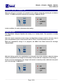
While the equalization charge is in progress, the MRG Front Panel shows the message
“EQUALIZING”:
With this timing system, the equalization is performed only in the weekend, when the battery
remains connected to the charger for more than 15 hours after the completion of the charge.
At the end of the equalization, the charger will remain in stand-by mode, while the front panel
gives the message “COMPLETE”:
__________________________________________________________________________________________________________________________________________________
Page 12/14
ES2400 – ES2403 – ES4800 - ES6000
User's Manual
___________________________________________________________________________________________________________________________________________________
QUICK TEST FUNCTION
CAUTION!
Risk of electrical shock!
The charger can be serviced by qualified personnel only.
Before to open the cabinet, disconnect the charger from battery and AC main supply.
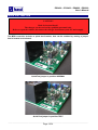
The MRG controller includes a quick test function, that can be enabled by moving a jumper
that is located on the board.
QuickTest jumper in position NORMAL
QuickTest jumper in position TEST
__________________________________________________________________________________________________________________________________________________
Page 13/14
ES2400 – ES2403 – ES4800 - ES6000
User's Manual
___________________________________________________________________________________________________________________________________________________
ATTENTION!
It's always necessary to keep the battery disconnected
while moving the QuickTest jumper.
When the jumper is set to position NORMAL, the MRG controller works normally.
When the jumper is set to position TEST, the MRG controller performs the complete charge
cycle in seconds, instead of minutes.
When a battery is connected:
•
if the voltage is lower than the gassing value, the EagleSmart will go in Emergency
Stop after 20-30 seconds.
•
If the voltage is higher than the gassing value, the EagleSmart will terminate the
charge and pass to the automatic equalize in a few seconds.
ATTENTION!
After performing a quick test cycle, make sure to move the jumper to
position NORMAL before to put the charger in service.
If the QuickTest jumper remains in position TEST, each charge
cycle will terminate within 20-30 seconds, therefore the battery will
not be charged!
- End of manual -
__________________________________________________________________________________________________________________________________________________
Page 14/14
'
%
%
$#
!
$
$
$
%
# !# $#
"
! "
! #
)
#
'
%
%
& '
&
&
&
'&
!
!
!
!
$
!
'
$
%
%
%
%
(%
$
$
$
!
$#
$+,+./ +0*
* +,-
! "
!
!
-
-
-
!
!
.
-! "
-
-
-
!-
-
!
$%%
$%%
!
"
"
"
"
#
"
'('*+ %',&
&%%'()
!!
"
"!
"!
" #
!
"
#
! "
!
!
!
$%%
$%%
"!
" #
!
.
#
#
.
.
#
#
.
!
#
!
! "
" "
#
!
#
#
"
'('*+ %',&
&%%'()
/
0
"
0
0
-
!
!
!
-"
"
! "
1
0! "
0
0
0
!0
0
"
!
"
"
!!
"
"!
"
"
"
"
ES2400 – ES2403 – ES4800 – ES6000
User's Manual
___________________________________________________________________________________________________________________________________________________
Bassi Bruno elettromeccanica & C. S.n.c.
Via Mensa 3/2, 48020 S. Maria in Fabriago – Lugo (RA)
Tel +39 0545 995008
Fax +39 0545 995006
[email protected]
__________________________________________________________________________________________________________________________________________________