1
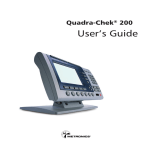
PST-7000 Series
USER’S MANUAL
Rev. A
L3 L4
L2
L1
L0 LP
L2
L1
L0
L3
LP
L4
SOME IMPORTANT NOTICES
FCC NOTICE
This equipment generates, uses, and can radiate radio frequency energy and, if not installed and used in accordance
with the instructions manual, may cause interference to radio communications. It has been tested and found to comply with limits
for a Class A digital device pursuant to subpart J of Part 15 of FCC Rules, which are designed to provide reasonable protection
against interference when operated in a commercial environment. Operation of this equipment in a residential area is likely to
cause interference in which case the user at his own expense will be required to take whatever measures to correct the
interference.
WARRANTY
This equipment contains no user serviceable parts and as such should be only opened by authorized technicians,
failure to comply with this will void any warranty that is in force. The user should consult an authorized dealer or representative
of Posiflex if the equipment fails to perform according to expectation.
The manufacturer cannot be held responsible for any damage caused or any hazard generated by improper use of this
equipment.
SAFETY
This equipment should be connected to the main power source in a safe manner and should conform to the local
electrical safety regulations.
This equipment also contains batteries of one or more types of chemistry. It is important that they are stored, handled
and disposed of in a safe manner without hazard to the environment and again in a manner that is consistent with the local
regulations for health and safety.
Additional information may be available in the Supplemental Notices.
SUPPLEMENTAL NOTICES
The Posiflex range of PST terminals are designed for use on a worldwide basis and as such may be required to carry
supplemental documentation to conform to the legal and other requirements of sale within the intended region. Please make sure
that any Supplemental Notices shipped with this equipment are consulted before any installation procedures are attempted
DISCLAIMER:
Considerable effort has been taken to ensure accuracy in compiling this manual but no liability can be accepted for
any errors or omissions. It is the responsibility of the user to ascertain that the equipment is suitable for the intended purpose and
to take adequate steps to safeguard data and to comply with the law.
The details for hardware and software quoted in this manual are liable to change without notice. They do not
constitute a description of any goods or services nor a commitment on behalf of the manufacturer.
The above statements do no affect your statutory rights.
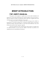
ABOUT THIS MANUAL
This manual assists the user to install and to utilize the hardware of the PST7000 series which is a member of the
POSIFLEX integrated point-of-sale terminal product family. The PST7000 is a compact point-of-sale system that utilizes the
most up-to-date technology in POS business machine and combines the performance and affordability of personal computers
with the elegance and reliability of business machine. The PST7000 also provides the built-in networking capability for easy
communication among multiple terminals in addition to the data transfer and control through back office server.
The manufacturer of the PST7000 series heartily apologizes to the user for reserving the right to change or to modify
this manual without notice due to the rapid and constant progress and improvement on science and technology. The user may
always obtain the most up to date information through our web site: http://www.posiflex.com.tw/ or http://www.posiflexuk.com/
or http://www.posiflexusa.com/
© Copyright Mustek Corp. 2000
All rights are strictly reserved. No part of this documentation may be reproduced, stored in a retrieval system, or
transmitted in any form or by any means, electronic, mechanical, photocopying, or otherwise, without the prior written consent
from Mustek Corp. the publisher of this documentation.
TRADE MARKS AND SERVICE MARKS
POSIFLEX is a registered trademark of Mustek Corp..
Other brand and product names are trademarks and registered trademarks and service marks of their respective
owners.
This equipment conforms to the requirements of 89/336/EEC. Please see supplemental notices and additional information.
CMANUPST7000
TABLE OF CONTENTS
BRIEF INTRODUCTION · · · · · · · · · · · · · · · · · · · · 1 -
1
THE USER’S MANUAL· · · · · · · · · · · · · · · · · · · · 1 - 1
THE PRODUCT · · · · · · · · · · · · · · · · · · · · · · · · 1 - 2
OVERVIEW · · · · · · · · · · · · · · · · · · · · · · · · 1 CONFIGURATION · · · · · · · · · · · · · · · · · · · · 1 THE BASIC POSiFLEX MODELS· · · · · · · · · · · · · 1 THE STANDARD FEATURES · · · · · · · · · · · · · · 1 Easy Accessible Service Windows · · · · · · · · · · 1 Non-Volatile Memory · · · · · · · · · · · · · · · 1 Ethernet Networking · · · · · · · · · · · · · · · ·1 Numerical Keypad · · · · · · · · · · · · · · · · 1 Keyboard Memory · · · · · · · · · · · · · · · · 1 6 Position Key Switch· · · · · · · · · · · · · · · 1 Direct Controlled Cash Drawer Port· · · · · · · · · · 1 Customer Display Port· · · · · · · · · · · · · · · 1 Cashier Display Port· · · · · · · · · · · · · · · · 1 Serial Ports · · · · · · · · · · · · · · · · · · · 1 Parallel Port · · · · · · · · · · · · · · · · · · · 1 USB Device Connection · · · · · · · · · · · · · · 1 Modem Ring-Up, LAN And Alarm Wake Up · · · · · · 1 UPS Function · · · · · · · · · · · · · · · · · · 1 THE OPTIONAL ITEMS · · · · · · · · · · · · · · · · 1 MSR · · · · · · · · · · · · · · · · · · · · · · 1 Customer Display · · · · · · · · · · · · · · · · · 1 Bar Code Scanner · · · · · · · · · · · · · · · · · 1 Audio Line Output Port · · · · · · · · · · · · · · 1 PCMCIA Control Board · · · · · · · · · · · · · · 1 2-in-1 Cash Drawer Control Cable · · · · · · · · · · 1 DRAM Memory Expansion · · · · · · · · · · · · · 1 -
i
2
2
2
3
3
3
3
3
3
3
4
4
4
4
4
4
5
5
5
5
5
5
5
5
6
6
· · · · · · · · · · · · · · · ·1 QWERTY Keyboard · · · · · · · · · · · · · · · ·1 POS Printer · · · · · · · · · · · · · · · · · · · 1 UPS Battery · · · · · · · · · · · · · · · · · · · 1 Integrated CD ROM Drive · · · · · · · · · · · · · 1 SYSTEM BOX CONTENTS · · · · · · · · · · · · · · · · · 1 MAIN SYSTEM UNIT · · · · · · · · · · · · · · · · · · · 1 CASHIER DISPLAY CARTON · · · · · · · · · · · · · · ·1 CUSTOMER DISPLAY CARTON · · · · · · · · · · · · · 1 PST ACCESSORIES CARTON· · · · · · · · · · · · · · · 1 -
6
6
6
6
7
7
7
7
7
8
PARTS IDENTIFICATION · · · · · · · · · · · · · · · · · · · 2 -
1
INSTALLATION GUIDES· · · · · · · · · · · · · · · · · · · ·3 -
1
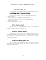
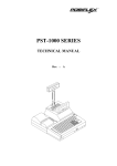
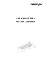
Variety of Key Tops
IMPORTANT· · · · · · · · · · · · · · · · · · · · · · · · · · 3 - 1
SERVICES WINDOWS · · · · · · · · · · · · · · · · · · · · 3 - 1
PUTTING IN UPS BATTERY · · · · · · · · · · · · · · · · 3 - 4
MONITOR · · · · · · · · · · · · · · · · · · · · · · · · · · · 3 - 4
LCD CASHIER DISPLAY · · · · · · · · · · · · · · · · · · 3 - 7
CUSTOMER DISPLAY · · · · · · · · · · · · · · · · · · · · 3 - 8
PROGRAMMABLE KEYBOARD · · · · · · · · · · · · · · 3 - 9
INTERNAL KB WEDGE BARCODE SCANNER · · · · · 3 -14
INTERNAL CONNECTION · · · · · · · · · · · · · · · · 3 -14
PS/2 MOUSE · · · · · · · · · · · · · · · · · · · · · · · · · · 3 -16
PRINTER · · · · · · · · · · · · · · · · · · · · · · · · · · · · 3 -17
AUDIO LINE OUTPUT · · · · · · · · · · · · · · · · · · · ·3 -18
CASH DRAWER · · · · · · · · · · · · · · · · · · · · · · · · 3 -19
AC POWER · · · · · · · · · · · · · · · · · · · · · · · · · · · 3 -20
USING THE PST SYSTEM · · · · · · · · · · · · · · · · · · · 4 -
1
BEFORE POWER ON · · · · · · · · · · · · · · · · · · · · 4 - 1
VENTILATION · · · · · · · · · · · · · · · · · · · · · · 4 - 1
OPERATING ENVIRONMENT · · · · · · · · · · · · · · 4 - 1
ii
POWER SUPPLY· · · · · · · · · · · · · · · · · · · · · · 4 - 1
PRINTER DC POWER SUPPLY · · · · · · · · · · · · · · 4 - 1
VGA DISPLAY PORT · · · · · · · · · · · · · · · · · · · 4 - 2
CUSTOMER DISPLAY· · · · · · · · · · · · · · · · · · · 4 - 2
SERIAL PORT – COM1 · · · · · · · · · · · · · · · · · · 4 - 2
MONITOR (FOR PST7000/PST7300) · · · · · · · · · · · · 4 - 3
MECHANICAL OPERATION · · · · · · · · · · · · · · · 4 - 3
TURN ON THE MONITOR · · · · · · · · · · · · · · · · 4 - 4
DISPLAY CONTROLS· · · · · · · · · · · · · · · · · · · 4 - 4
CONTRAST CONTROL· · · · · · · · · · · · · · · · · 4 - 4
BRIGHTNESS CONTROL · · · · · · · · · · · · · · · · 4 - 4
HORIZONTAL PHASE CONTROL· · · · · · · · · · · · 4 - 4
VERTICAL SIZE CONTROL· · · · · · · · · · · · · · · 4 - 5
DISPLAY UTILITY DRIVER· · · · · · · · · · · · · · · · 4 - 5
LCD (FOR PST7030/PST7350) · · · · · · · · · · · · · · · · 4 - 6
MECHANICAL OPERATION · · · · · · · · · · · · · · · 4 - 6
DISPLAY UTILITY DRIVER· · · · · · · · · · · · · · · · 4 - 7
CUSTOMER DISPLAY · · · · · · · · · · · · · · · · · · · · 4 - 7
VERSATILE MECHANICAL MANEUVERABILITY · · · 4 - 7
PROGRAMMABLE KEYBOARD · · · · · · · · · · · · · · 4 - 8
BASIC FUNCTIONS · · · · · · · · · · · · · · · · · · · · 4 - 9
STRUCTURE· · · · · · · · · · · · · · · · · · · · · · · · 4 - 9
6 POSITION KEY-LOCK· · · · · · · · · · · · · · · · · · 4 -11
APPLICATION EXAMPLE · · · · · · · · · · · · · · · · 4 -13
EXAMPLE 1· · · · · · · · · · · · · · · · · · · · · · 4 -13
EXAMPLE 2· · · · · · · · · · · · · · · · · · · · · · 4 -14
FURTHER IDEAS · · · · · · · · · · · · · · · · · · · 4 -14
SPECIAL FEATURES · · · · · · · · · · · · · · · · · · · 4 -15
SECURITY LOCK OFF · · · · · · · · · · · · · · · · · 4 -15
MULTI-PAGE PROGRAMMING · · · · · · · · · · · · · 4 -15
MULTI-LEVEL PROGRAMMING · · · · · · · · · · · · 4 -15
ANSWER BACK · · · · · · · · · · · · · · · · · · · · 4 -15
SPEED CONTROL OF OUTPUT · · · · · · · · · · · · · 4 -16
iii
· · · · · · · · · · 4 -16
SOFTWARE SWITCH OFF · · · · · · · · · · · · · · · 4 -16
CONVENIENCE IN PROGRAMMING· · · · · · · · · · · 4 -16
INSTANT CONTENT UPDATE · · · · · · · · · · · · · 4 -17
PRELOADED KEY DEFINITIONS· · · · · · · · · · · · · 4 -18
MSR · · · · · · · · · · · · · · · · · · · · · · · · · · · · · · · 4 -21
LED INDICATORS · · · · · · · · · · · · · · · · · · · · · · 4 -22
FRONT DOOR · · · · · · · · · · · · · · · · · · · · · · · · · 4 -23
EXTERNAL PC KBYBOARD · · · · · · · · · · · · · · · · 4 -23
3.5” FDD · · · · · · · · · · · · · · · · · · · · · · · · · · · · 4 -23
POWER ON/OFF CONTROL · · · · · · · · · · · · · · · · 4 -24
EXTERNAL POWER ON SWITCH · · · · · · · · · · · · 4 -24
POWER ON/OFF PUSH SWITCH · · · · · · · · · · · · · 4 -24
SOFTWARE OFF SWITCH · · · · · · · · · · · · · · · · 4 -24
PRESET POWER ON CONTROL · · · · · · · · · · · · · 4 -25
EMERGENCY POWER OFF · · · · · · · · · · · · · · · ·4 -25
REAR ROOM· · · · · · · · · · · · · · · · · · · · · · · · · · 4 -26
PRINTER · · · · · · · · · · · · · · · · · · · · · · · · · · · · 4 -26
USB· · · · · · · · · · · · · · · · · · · · · · · · · · · · · · · · 4 -26
BUILT-IN UPS WITH BATTERY · · · · · · · · · · · · · · 4 -26
TIME CONTROL ON OUTPUT HOLD
iv
PST-7000 series user’s manual – BRIEF INTRODUCTION
BRIEF INTRODUCTION
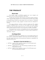
THE USER’S MANUAL
The purpose of this manual is to guide the user in the initial installation and
general use of the Posiflex PST7000 series of POS terminals. It does not, however,
make any attempt to explain any application software that may be supplied with it and
which of course is an essential component of any system.
We intend to provide our customers with all the advantages made available in
the advances of electronic technology by evolving the product design to incorporate
appropriate changes and improvements, as such some detail differences may exist
between this manual and the equipment supplied.
The latest information on this terminal and our other products is available from
our authorized dealers or on our web site. Details of the latter are printed in our
supplemental notices and additional information.
1-1
PST-7000 series user’s manual – BRIEF INTRODUCTION
THE PRODUCT
Overview
The Posiflex range of PST7000 terminals have been designed and
manufactured to meet the high end demand on POS system.
The PST range incorporates all the advances of personal computer technology
within a rugged housing designed for use in a hostile retail environment. By providing
an integrated design, Posiflex has retained many of the secure features of a traditional
ECR and has avoided the wiring “spaghetti” associated with more traditional PC
solutions.
The system architecture conforms to both the original open ISA standard
(outlined in IEEEP996) and to the newer PCI bus standard. This Open Standard
Architecture ensures that this terminal can use the very wide range of PC application
software and development tools that are now inexpensively available and abundant.
The terminal may be used as a self-contained unit or by using the integrated
network interface as one of several terminals in a network system controlled by a
“back office” computer.
Configuration
The PST7000 terminal may be supplied as one of several models and may also
have a number of optional items added to it. These may be from the Posiflex range or
from other suppliers but because of the Open System Architecture, compatibility will
in general not be an issue.
THE BASIC POSIFLEX MODELS ARE:
•
•
•
PST7000 – supplied with the capability to support a VGA CRT monitor and a
matrix programmable keyboard
PST7050 – supplied with a 12” color TFT LCD display installed and a matrix
programmable keyboard
PST7300 – supplied with the capability to support a VGA CRT monitor and a
PC layout programmable keyboard
1-2
PST-7000 series user’s manual – BRIEF INTRODUCTION
•
PST7350 – supplied with a 12” color TFT LCD display installed and a PC layout
programmable keyboard
THE STANDARD FEATURES ARE:
Easily Accessible Service Windows
There are several windows in bottom chassis for RTC battery easy
replacement, COM port power enable/disable easy setting, SO-DIMM upgrade and 1st
IDE HDD replacement.
Non-Volatile Memory
The standard non-volatile memory of PST7000 series is 32 KB. This nonvolatile memory is used by the software system provider to safeguard the data storage;
or, if worked in cooperation with the system integrator, can be used for fiscal memory
systems.
Ethernet Networking
The standard network port works with both 10 Base T and 100 Base T.
Numerical Keypad
The standard keyboard (112 keys) layout in PST7000 series contains an area
for numerical keypad for easier numerical inputs.
Keyboard Memory
The standard keyboard memory of the programmable keyboard of PST7000
series is 8 KB.
6 Position Key Switch
Every PST7000 system is equipped with a 6 position key switch for several
purposes. This key switch supports security lock off and multi-page programming of
the programmable keyboard, answer back code and software switch off functions. 4
different type of keys are provided for different accessibility.
1-3
PST-7000 series user’s manual – BRIEF INTRODUCTION
Direct Controlled Cash Drawer Port
There is one direct controlled cash drawer port in the rear room of each
PST7000 system. This port controls one cash drawer (mostly recommended with the
CR3X00/CR4X00) with the standard accessory cable CCBLA-180. This port can
control two cash drawers independently using the optional cable CCBLA-238.
Customer Display Port
Every PST system provides a customer display port to drive any Posiflex
customer display. However, the system case with a base tube of a customer display is
different from that without a customer display.
Cashier Display Port
The cashier display ports utilized in PST7000/7300 and PST7050/7350 are
different to each other. The monitor used in PST7000 and PST7300 is connected to a
3 x 5 D VGA connector while the TFT LCD used in PST7030 and PST7350 is
connected to a 26 pin SCSI type specialized connector. Both connectors exist and
function on any of the models.
Serial Ports
There are 4 serial ports in a PST7000 system. COM1 is shared by the customer
display port and the direct driven cash drawer port. COM1 is capable of providing a
+5 V DC supply. COM2, COM3 and COM4 each are capable of providing
independently a +5 V DC or a +12 V DC supply. All these DC supplies are achieved
through internal jumper setting and they are all defaulted to give no DC supply at
delivery. The COM3 and COM4 ports can be disabled by internal jumper setting if
any resource conflict occurs between any added adapter card and these 2 ports.
Parallel Port
Each PST system is equipped with a parallel port that supports SPP/EPP/ECP.
USB Device Connection
The PST7000 series is equipped with two connectors for connection of USB
(Universal Serial Bus) devices.
1-4
PST-7000 series user’s manual – BRIEF INTRODUCTION
Modem Ring-Up, LAN And Alarm Wake-Up
The PST7000 series can be turned on automatically upon an incoming COM
port Modem call or LAN status or data packet received on LAN or a preset
time/day/week/month.
UPS Function
The PST7000 series has a built-in UPS function that will protect the system
from accidental AC power failure if an optional UPS battery is installed.
THE OPTIONAL ITEMS ARE:
MSR – Magnetic Stripe Card Reader supplied as:
•
•
•
2 track reader (track 1 & 2)
2 track reader (track 2 & 3)
3 track reader (track 1, 2 & 3)
Please note that the card slot is always present whether or not the MSR is
fitted. A blanking module is fitted in place of the MSR if the MSR is not supplied.
Customer Display – This can be supplied in a variety of types:
•
•
•
2 line by 16 character LCD display (PD201)
2 line by 20 character VFD display (PD2101/PD2201)
Graphic LCD display (PD7101)
Bar Code Scanner
•
•
CCD scanner (CD-2800K) with 80mm width read capability
Laser Scanner (LS6080K/LS6060K)
Audio Line Output Port
This option requires different mainboard and should be ordered before the
delivery. For application of this option, a pair of booster speakers are recommended.
PCMCIA Control Board (PST060)
This board works on the PCI bus slot of the PST7000 system and accepts type
II or type III PCMCIA card.
1-5
PST-7000 series user’s manual – BRIEF INTRODUCTION
2-in-1 Cash Drawer Control Cable
This cable CCBLA-238, when added to the CR port of the PST7000 series,
can be used to control two Posiflex CR-3100 or CR-3200 or CR-4000 cash drawers.
DRAM Memory Expansion
The standard memory size is 32 MB and can be expanded to 512 MB in 2 SODIMM modules.
Variety of Key Tops
•
•
•
•
•
Quad Key
Horizontal Double Key
Vertical Double Key
Single Key
Blank Key
QWERTY Keyboard
The standard equipped programmable keyboard is a 112 keys matrixed
programmable keyboard. The optional “QWERTY” layout keyboard provides a more
type-writer-like area plus a numerical keypad and 53 programmable keys. This option
is available for France, Germany, Italy, Netherlands,Portugal, Spain, Sweden/Finland,
United Kingdom or United States.
POS Printer
•
PP-1000 series Posiflex POS printers: friction paper feed, serial or parallel
interface, single or dual color printing, 7 pin dot matrix impact printer.
• PP-2000 series Posiflex POS printers: friction paper feed, serial or parallel
interface, 2 stations 9 pin dot matrix impact printer.
• PP-3000 series Posiflex POS printers: friction or sprocket paper feed, serial or
parallel interface, 9 pin dot matrix impact printer
• PP-4000 series Posiflex POS printers: friction paper feed, serial or parallel
interface, line thremal printer.
UPS Battery
2.3 AH 12V Lead Acid Battery
1-6
PST-7000 series user’s manual – BRIEF INTRODUCTION
Integrated CD ROM Drive
This option includes case modification and should be ordered berfore delivery.
SYSTEM BOX CONTENTS
•
•
•
•
•
When you receive the system box you will find it contains several items:
Main system unit
Cashier display carton for LCD model PST7050 or PST7350
Customer display carton if an option of customer display is ordered
PST accessories carton
Other optional components as ordered.
Main System Unit
The main system unit is supplied with the key tops of the programmable
keyboard assembled without the transparent key caps.
Cashier Display Carton
When the order is PST7000 or PST7300, the purchased VGA mono or VGA
color monitor will be shipped in a separate box from the main system unit. When the
order is PST7050 or PST7350, the package for the 12.1” color TFT LCD is inserted in
a side within the system box.
Customer Display Carton
This is a separate carton within the main carton and contains the customer
display (sometimes called a pole display) when an option of customer display is
purchased with the PST system.
1-7
PST-7000 series user’s manual – BRIEF INTRODUCTION
PST Accessories Carton
This contains most of the small parts and loose items for PST7000 and
PST7050 as follows:
• This user’s manual
• 1 set of keys (4 pieces) for keyboard key switch
• 1 set of keys (2 pieces) for front door lock
• Keyboard type dependent accessories as listed below
• 3½ inch diskette (4 pieces) with driver utilities
• Cable tie (5 pieces)
• Velcro patches (4 pieces) for printer installation.
• VFD terminator (1 piece)
• COM1 terminator (1 piece)
• Main power cord (1 piece)
• Cash Drawer cable (CCBLA-180) (1 piece)
• Printer power cable (1 piece)
• Dust cover (1 piece)
The content of keyboard type dependent accessories is listed below. Please
note that these parts are different in size between the KB112 for PST7000/PST7050
and the KB136 for PST7300/PST7350. The rough measurements in millimeters of the
key surfaces are also noted below:
Accessories for models
PST7000/PST7050
PST7300/PST7350
Qty Note
Qty Note
Legend sheet in 4 colors (set)
1
P/N:CLABPSTK
1
B112-1
P/N:CLABPSTH
KB112
Key cap removal tool (key clip)
1
P/N:QC2000
P/N:QCH2000
Single key transparent cap
92 22 x 18
52 18 x 18
Vertical double key transparent cap
2
22 x 37
1
18 x 37
Horizontal double key transparent cap 0
45 x 18
0
37 x 18
Quad key transparent cap
1
37 x 45
(not applicable)
Blank key
2
22 x 18
(not applicable)
1-8
1
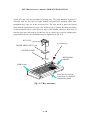
PST-7000 series user’s manual –PARTS IDENTIFICATION
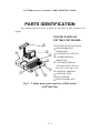
PARTS IDENTIFICATION
The following pictures show in detail the assembly of PST terminals and
options.
MAJOR PARTS OF
PST7000 CRT MODEL:
°
±
L3 L4
L2
L1
L 0 LP
²
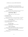
¬ POWER ON SWITCH KNOB
- PROGRAMMABLE
¯
®
¬
³
´
KEYBOARD
® POSITION KEY SWITCH
¯ CASHIER DISPLAY
(MONITOR)
° CUSTOMER DISPLAY
(OPTIONS INCL. PD-2101,
PD-2201 or PD-7001/7101)
± OPTIONAL PRINTER
² OPTIONAL MSR
³ FRONT DOOR
´ FRONT DOOR LOCK
Fig. 2 - 1 Major parts seen from front of CRT model
(PST7000/7300)
2-1
PST-7000 series user’s manual – BRIEF INTRODUCTION
MAJOR PARTS OF
PST7050 LCD MODEL:
°
±
L4
L3
L3 L4
L2
L2
L1
L1
L0
L0 LP
LP
²
¯
®
¬
³ ´
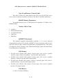
¬ POWER ON SWITCH KNOB
- PROGRAMMABLE KEYBOARD
® POSITION KEY SWITCH
¯ CASHIER DISPLAY (LCD)
° CUSTOMER DISPLAY
(OPTIONS INCL. PD-2101,
PD-2201 or PD-7001/7101)
± OPTIONAL PRINTER
² OPTIONAL MSR
³ FRONT DOOR
´ FRONT DOOR LOCK
Fig. 2 - 2 Major parts seen from front of LCD model
(PST7050/7350)
2-2
PST-7000 series user’s manual –PARTS IDENTIFICATION
¬
DETAIL PARTS:
¬ CRT MONITOR
- CABLE COVER
® MONITOR HOOK
¯ BOWL SHAPED
-
TILT BASE
° MOUNTING LUG
± SWIVEL BASE
®
¯ ² SWIVEL BASE
° ³ HANDLE
DISPLAY
± ´ PLATFORM
INNER POLE
² µ BASE TUBE
´
µ
11
RAIL COVER
³
11
L3 L4
L2
L1
L0 LP
Fig. 2 - 3a Detail parts seen from front of CRT model
2-3
PST-7000 series user’s manual – BRIEF INTRODUCTION
¯
°
¬
±
L3 L4
L2
L1
L0 LP
-
²
³
®
´
µ
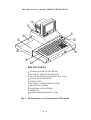
DETAIL PARTS:
¬ POWER ON INDICATOR (GREEN)
- STAND-BY INDICATOR (ORANGE)
® KEY TOPS WITH TRANSPARENT KEY CAPS
¯ VENTILATION OPENINGS
° TUBE COVER
± BATTERY COMPARTMENT COVER
² PRINTER PLATFORM
³ MSR INDICATOR (OPTION)
´ MSR SLOT
µ MSR READER HEAD INDICATOR
Fig. 2 - 3b Detail parts seen from front of CRT model
2-4
PST-7000 series user’s manual –PARTS IDENTIFICATION
EXTERNAL KEYBOARD PORT
(5 P DIN JACK)
POWER ON/OFF
PUSH SWITCH
3.5” FDD
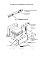
Fig. 2 - 4 Inside the front door
VENTILATION
OPENINGS
PRINTER
PLATFORM
MONITOR
DISPLAY
PLATFORM
BATTERY
COMPARTMENT
COVER
BACK DOOR
LATCH
VGA CABLE
BACK DOOR
LATCH
CABLE COVER
BACK DOOR
Fig. 2 - 5 Rear view of PST (CRT model in this example)
2-5
PST-7000 series user’s manual – BRIEF INTRODUCTION
AC INLET
AC VOLTAGE SELECTION SWITCH
COM 2
USB 2
COM 4
LPT 1
COM 3
CR
LCD
DISPLAY
24 VDC
CUSTOMER DISPLAY
(PD-2101/2201/7001)
VGA
USB 1
LAN
Fig. 2 – 6 Inside the back door
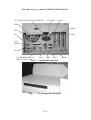
Fig. 2 – 7 The integrated CD-ROM
2-6
COM 1
PST-7000 series user’s manual – INSTALLATION GUIDES
INSTALLATION GUIDES
IMPORTANT
PLEASE DO NOT CONNECT THE POWER CORD OR TURN ON
THE MAIN UNIT UNTIL YOU HAVE FULLY READ THE INSTALLATION
GUIDES AND FOLLOWED THE INSTRUCTIONS!!!
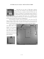
SERVICE WINDOWS
At the bottom of PST7000 terminals, there are four service windows that can
be opened for hardware upgrade/installation without the need to open the whole
structure. Please refer to the bottom view picture below for locations of these
windows and their fixation screws.
1 Fixation Screw for Window
for COM Port Jumper Setting
4 Fixation Screws for Window
for 1st IDE HDD
5 Fixation Screws for Window
for System Battery & DRAM
1 Fixation Screw for Window
for UPS Battery Connector
In the COM port jumper setting window, there are jumpers
for defining how the power supply to COM ports are organized.
Please have the jumpers changed only by a qualified technician
who can take appropriate action under the guidance from the
Technical Manual of this product series. Screw back the cover
plate by first inserting the opposite edge from the screw hole to the bottom chassis.
3-1
PST-7000 series user’s manual – BRIEF INTRODUCTION
When the cover plate of the 1st IDE HDD window is removed, one can see the
1st IDE HDD is screwed on the cover plate through 4 screws with rubber washers on
both sides of the cover plate. Replace the HDD by unscrewing the 4 screws with
rubber washers and disconnecting the data and power connection to the HDD by a
qualified technician only when neccessary. Please always remember to put the
rubber washers back on bothe sides of the cover plate to protect the HDD.
Unscrew the 4 screws with rubber washers to
remove the 1st IDE HDD. Always put on the
rubber washers when screwing back the HDD.
Opening the window for system battery & DRAM, there are three openings in
the bottom chassis. The system battery socket in one opening, the two SO DIMM
sockets in another and there is another opening for reserves.
Reserved opening
System Battery
Socket for System Battery
SO DIMM Sockets
SO DIMM
The battery socket accepts a 3 V button cell Lithium battery (CR2032)
required to support the system real time clock. A new Lithium battery can support the
system RTC for about 3 years. After the battery is nearly exhausted, the user must
change a new battery otherwise the system RTC and system configuration setup will
be lost. The two SO DIMM sockets accept Small Outlined Dual In-line Memory
Module each may be up to 256 MB.
3-2
PST-7000 series user’s manual – INSTALLATION GUIDES
Removing the cover plate of UPS battery connecter
window, there is the connector for the UPS battery. When the
optional UPS battery is purchased with the PST7000 series, the
UPS battery is installed in its compartment but the connector is
not connected due to some security concerns. If the user wants to
add a later purchased UPS battery into a PST7000 system
without UPS battery originally, he/she may refer to the next paragraph for putting in
the UPS battery and make the connection as illustrated here.
After inserting the connector from the UPS battery to the socket in the UPS
battery connector window, please insert the UPS battery cable wire by wire into the
protective clamp on edge of the cover plate for the connector. Screw back the cover
plate by first inserting the opposite edge from the screw hole to the bottom chassis.
Make sure the whole
UPS battery cable is well
inserted in the protective
clamp at the edge of the
cover plate as the picture
below. The bottom chassis
should look like the picture
at the right after all cover
plates reinstalled.
3-3
PST-7000 series user’s manual – BRIEF INTRODUCTION
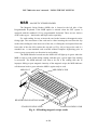
PUTTING IN UPS BATTERY
First remove the CD-ROM platform if this option is installed. Remove the
battery cover first by pressing down at one end and pushing out the battery cover as
shown. The user may find the UPS battery lying in the battery compartment if this
option is ordered. Connect the cable through the opening on the wall toward the rear
room of the cabinet and through the bottom of the rear room to the connector in the
bottom chassis as described in the previous paragraph. The Velcro strips in the
accessories kit may be used to firmly anchor the UPS battery into position.
OPENING TO
REAR ROOM
DISPLAY
PLATFORM
BATTERY
COVER
L3 L4
L2
L1
L0 LP
PRESS THIS END
DOWN AND
PUSH THIS
WAY TO OPEN
PRINTER
PLATFORM
Fig. 3 - 1 Removal of battery cover
MONITOR
Upon receiving the CRT type PST7000, the monitor comes in a separate box.
The installation of the monitor onto the PST product is as following. First take both
the main unit and the monitor out of their boxes. Hold the monitor with the screen
facing downward allowing the two mounting holes at the bottom toward the two
mounting lugs on the bowl at the top of the PST main unit (ref. Fig. 3-2). Let the two
mounting lugs insert into the two mounting holes, then gently push and rotate the
3-4
PST-7000 series user’s manual – INSTALLATION GUIDES
monitor backward 90° to have the monitor sit on the bowl mounted on top of main
unit. On completion of this maneuver the rear of the monitor will “click” into position
over the monitor hook and will be securely retained into position.
MONITOR MOUNTING LUGS
HOOK
MOUNTING HOLES
BOWL
L3 L4
L2
L1
L0 LP
Fig. 3 - 2 Mounting monitor
The next step is to pass the monitor cable(s) through a square hole at the back
edge of main unit. Open the back door by sliding two back door latches (ref. Fig. 2-5)
at the bottom of back door toward the center. The back door is easily removable.
Remove the cable cover by pulling the latch on the underside of the cable cover (ref.
Fig. 3-3). Connect the VGA cable (and the AC cable to the AC outlet above the
socket for AC inlet if an AC type CRT such as the color monitor is delivered in stead
of DC type) to the VGA connector. This connector may be marked as “display”.
Secure the two hex screws on the display connector. Put the cable cover back onto the
square hole with the hook end in position first and then press the cover down to
position. You will hear another click sound and the cable cover is well mounted.
3-5
PST-7000 series user’s manual – BRIEF INTRODUCTION
VGA connector
HOOK
LATCH
CABLE COVER
Fig. 3 - 3 Cable connection of monitor (for PST7000)
To remove the monitor, first disconnect the cable(s) then pull the latch on the
underside of the cable cover to remove the cable cover (ref. Fig. 3-3). Then pull the
monitor hook lever at the bottom at rear side of the bowl by finger, then raise and
rotate the monitor forward till the CRT front is facing downward. You will then be
able to remove the monitor easily.
The VGA connector in the LCD models PST7050/PST7350 can be connected
to a stand alone VGA monitor as an extra display. However, to use the extended dual
display mode (each screen showing different pictures), the VGA monitor will be
referred to as the first display and the shared VGA memory must be set to 8 MB.
3-6
PST-7000 series user’s manual – INSTALLATION GUIDES
LCD CASHIER DISPLAY
When the PST7050 or PST7350 is ordered, the user has to take the 12.1” TFT
LCD cashier display out from the cashier display carton and assemble it onto the main
unit per following instructions.
Unscrew and take out the pivot that is screwed on the display platform of the
main unit. Unfold the base of the operator display and insert it into the opening on the
display platform of the main unit till it clicks. Screw the pivot back to secure the base
of the cashier display on the display platform of the main unit as in Fig. 3-4. Remove
the cable cover on the display platform (same way as the instructions for CRT model)
and insert the 26 pin SCSI connector of the 12.1” TFT LCD through the hole into the
rear room. Reserve some sag in the cable so that the LCD cashier display will be
allowed to turn and reinstall the cable cover. Connect the 26 pin connector of 12.1”
TFT LCD to the LCD display connector in the rear room (ref. Fig. 3-4).
PIVOT
LCD DISPLAY
CONNECTOR
26 PIN MALE LCD
CONNECTOR
12.1” LCD
BASE OF
LCD
CABLE COVER
Fig. 3 – 4 Installing the cashier display
3-7
PST-7000 series user’s manual – BRIEF INTRODUCTION
CUSTOMER DISPLAY
When the PST7000 series is ordered with the customer display option, the
terminal will be delivered with the base tube for the display already fitted to corner of
the display platform.
The customer display head can be easily inserted into the base tube after first
inserting the signal cable. The release button on the base tube must be pulled out to
allow the inner tube of the display head to travel down into the base tube (ref. Fig. 35). Please ensure that the latching track on the inner-pole matches up with the release
button. Open the back door and find the connector marked “customer display” or
“VFD”. Please remove the VFD terminator from this connector and store in a safe
place. Insert the cable plug of the customer display into customer display connector
until a click sound is heard.
Please NOTE: The VFD connector must always be populated either with
the VFD terminator or a plug from the customer display (Failure to do this will
prevent COM1 from working correctly).
Close the back door then slide the two door latches outward and the
installation is completed. Please refer to the instructions in the part “TO USE THE
PST SYSTEM” for later adjustment on the most comfortable position and direction of
the customer display.
INNER
POLE
CABLE
GOES IN
FIRST
RELEASE
BUTTON
BASE TUBE
Fig. 3 - 5 Customer display installation
3-8
PST-7000 series user’s manual – INSTALLATION GUIDES
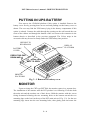
PROGRAMMABLE KEYBOARD
The PST terminal is equipped with an extremely versatile programmable
keyboard. In which up to 255 characters as well as diverse control functions may be
assigned to each key (subject to the 8KB maximum total storage limit). This feature
allows the programmer complete freedom in mapping the keyboard layout without
having to introduce software TSRs or .dlls into the PC host for application. (The
complete programming primer for the keyboard is in the technical manual). This
keyboard comes in 2 different layouts : KB112 for PST7000/PST7050 and KB136 for
PST7300/PST7350. The key tops of the 2 layout have different sizes for a single key,
so all the accessories for the 2 layout can not be mutually exchanged. However, they
are common in structure.
The keyboard is shipped from the factory with the key tops fitted, but without
the transparent key caps (these are in the accessories box). Also supplied with the
keyboard are 4 die cut self adhesive A4 label sheets that may be printed by most
conventional means with whatever legends are required by the application.
Because of the programmable nature of the keyboard the key layout may be
different from that envisioned by the application and therefore, may be arranged to
suit the convenience of the operator.
There are a number of types of key available:
• Single key with transparent key cap
• Vertical double key with transparent key cap (for KB112 only)
• Horizontal double key with transparent key cap (option for KB112 only)
• Quad key with transparent key cap (for KB112 only)
• Numeric keys with fixed legends (for KB112 only)
• Double key with transparent key cap (for KB136 only)
• Blank key for cluster separation
The user may use the key clip (to be found in the accessory box) to pull off the
key caps and apply the printed legend label on the key top then recap the transparent
key cap for identification (ref. Fig. 3-6).
3-9
PST-7000 series user’s manual – BRIEF INTRODUCTION
Key clip
Transparent key cap
Legend label
L3 L4
L2
L1
L0 LP
Fig. 3 - 6 Applying the label and locating the key cap
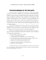
The user may also use a flat bladed screwdriver to remove the key tops (ref.
Fig. 3-7a, b & c) for proper arrangement of the key tops. The key clip should be
expanded to remove the key cap from the double key or the quad key (ref. Fig 3-8).
Fig. 3 - 7a
Removing key top
(Single key)
Fig. 3 - 7b
Removing key top
(Double key)
3 - 10
PST-7000 series user’s manual – INSTALLATION GUIDES
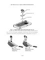
Fig. 3 - 7c
Removing the key top
(Quad key)
Fig. 3 - 8 The key clip
It is important to correctly orientate the key tops before they are inserted into
the keyboard frame (ref. Fig. 3-9); failure to do this could result in permanent
damage. There is, on one side of the square stem of the key top, a small latching tab,
this mates with a corresponding tab on the inside wall of the key top guide hole in the
way illustrated in Fig. 3-10a, Fig. 3-10b and Fig. 3-10c.
Latching tab
Key top
Keyboard frame
Fig. 3 - 9 Inserting the key top
3 - 11
PST-7000 series user’s manual – BRIEF INTRODUCTION
Blank key top
Latching tab
Tab in the guide hole
Fig. 3 - 10a Inserting a blank key top
Double key top
Latching tab
Tab in the guide hole
Fig. 3 - 10b Inserting a double key top
3 - 12
PST-7000 series user’s manual – INSTALLATION GUIDES
Quad key top
Latching tab
Tab in the guide hole
Fig. 3 - 10c Inserting a quad key top
The entire program contents of the keyboard should be saved prior to any use
of the PST terminal. The key contents include the contents of the multiple paged 112
keys of KB112 (or 51 plus 2 keys of KB136) and the answer back codes of the 6
position electronic key. The programming methods may be accomplished using the
following procedure with details explicitly explained in the Technical Manual.
1. Locate the program rwm.exe. This is normally stored on the utility diskette
supplied with the PST. The full path to this program is A:\kbdrv\rwm.exe if the diskette is placed in drive A:
Please check your supplemental notices and information for changes.
2. To save the current programmed layout execute rwm as follows:
rwm filename -r
This will save the layout in a file called: filename
Note: you may choose any name for the file obeying the normal DOS file
conventions. We recommend that you use the .tpl file extension.
3. To reload a previously saved layout from a file called filename, execute
rwm as follows:
rwm filename
3 - 13
PST-7000 series user’s manual – BRIEF INTRODUCTION
INTERNAL KB WEDGE BARCODE
SCANNER
The PST keyboard has been designed to provide a daisy chain interface (DCI)
capability such that it is possible to connect a number of suitable input devices in
series with each other. In this way each device can communicate with the application
software, as if it were an actual keyboard at which someone had typed the characters.
The terminal is supplied with two devices already in the daisy chain. The first
is the programmable keyboard followed by the magnetic stripe reader (MSR) if fitted.
It is possible to add additional devices to this daisy chain either as an internal
or external connection (ref. Fig. 3-11) subject to a maximum of 5 devices (this is
dependent on the electrical characteristics of the devices and may be less than 5
devices).
Internal Connection
This is the preferred method for a permanent connection and would typically
be used for bar code readers.
To access the internal connection you must remove the keyboard. To do this
first unlock the front door lock and then remove the two mounting screws from the
underneath of the chassis located just behind the front edge of the terminal. Once
these screws have been removed it is possible to lift the front edge of the keyboard
housing and then rotate the keyboard “up and back”. This then exposes the keyboard
controller on the underside of the keyboard (ref. Fig. 3-12). Connector A is normally
inserted into socket B (on controller C) when the terminal is supplied without an
additional DCI device. To add an internally connected DCI device A should be
removed from B and the new device inserted between them. Match the top edge of the
programmable keyboard with rear cabinet of main unit and close it to the bottom
chassis. Before closing it, the cables must be fixed to the bottom chassis with a cable
tie and a piece of cable cover at side of bottom chassis must be taken away. Mount
back the two screws from bottom side then the installation for internally connected
KB wedge device is done.
3 - 14
PST-7000 series user’s manual – INSTALLATION GUIDES
We strongly advise users to consult with their dealers to have an authorized
technician for such installation.
MALE DIN
KEYBOARD
CPU BOARD
FEMALE DIN
KB WEDGE
DEVICE
MALE DIN
FEMALE DIN
KB WEDGE
DEVICE
KB WEDGE
DEVICE
Fig. 3 - 11 Connection of multiple internal KB wedge devices
3 - 15
PST-7000 series user’s manual – BRIEF INTRODUCTION
Lift up front end after
unlocking and unscrewing
KB CPU BOARD
5PIN DIN MALE
DIN JACK
C
B
5PIN DIN MALE
A
5 PIN DIN FEMALE
CABLE OF INTERNAL
SCREWS
KB WEDGE DEVICE
Fig. 3 - 12 Installation of internal KB wedge device
PS/2 MOUSE
Unscrewing the 2 screws near the front bottom corners with the front door
unlocked, the programmable keyboard section can be raised up exposing part of the
EMI protection shield over the mainboard. On the front edge of the mainboard, there
is the PS2 mouse port. After connecting a PS2 mouse to this PS2 mouse port, please
remove the cable stopper on either side of the chassis and route the mouse cable
through the side opening before screwing back the keyboard section.
After the mechanical installation of the PS/2 mouse, the user should enable the
function of this mouse in the CMOS setup. Enter the CMOS setup by pressing “DEL”
key at system boot up, choose for “INTEGRATED PERIPHERALS” and make the
“PS/2 MOUSE” enabled. Save the configuration and exit the CMOS setup program.
The PS/2 mouse will then be ready for the control of the operation system.
3 - 16
PST-7000 series user’s manual – INSTALLATION GUIDES
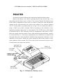
PRINTER
Assemble the printer following the instructions supplied with the printer.
Remove the battery cover first by pressing down at one end (ref. Fig. 3-13)
and pushing out the battery cover as shown. The user may find the UPS battery lying
in the battery compartment if this option is ordered. Connect the cable through the
opening on the wall toward the rear room of the cabinet to the connector marked
“LPT 1” (if the printer is a parallel printer as ref. Fig. 3-14). Or connect the cable to a
proper “COM” port (COM 1 through COM 4) according to the definition on the
application program (if the printer is a serial printer). The 24 VDC power cable should
be attached to the 24 VDC connector in the rear compartment if the printer is to use
this power supply from the terminal. These cables should be passed through “opening
A” as shown in fig 3-13. The battery compartment cover should now be replaced and
the signal and power cables should be attached to the appropriate connectors on the
underside of the printer. Finally the printer should be placed into position on the
printer platform of the terminal. The Velcro strips in the accessories kit may be used
to firmly anchor the printer into position.
OPENING TO
REAR ROOM
DISPLAY
PLATFORM
BATTERY
COVER
L3 L4
L2
L1
L0 LP
PRESS THIS END
DOWN AND
PUSH THIS
WAY TO OPEN
PRINTER
PLATFORM
Fig. 3 - 13 Removal of battery cover
3 - 17
PST-7000 series user’s manual – BRIEF INTRODUCTION
FROM PRINTER
PRINTER CABLE
Fig. 3 - 14 Example showing the connection of a parallel printer
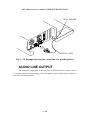
AUDIO LINE OUTPUT
The audio line output port in the rear room of PST7000 series accepts a stereo
3.5 Ø plug. Instead of connecting to the usual speaker, please make sure to connect it
to a pair of booster speakers.
3 - 18
PST-7000 series user’s manual – INSTALLATION GUIDES
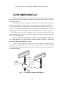
CASH DRAWER
The PST7000 is able to control most of the common cash drawers available on
the market. However, it is recommended that the Posiflex CR-3100 or CR-3200 or
CR-4000 or CR-4100 be used since the terminal has been designed to compliment this
cash drawer both mechanically and electrically.
The PST7000 will directly control the cash drawer using the cash drawer port
(CR) both to operate the opening mechanism and to monitor the drawer open status.
Both functions may be accomplished under software control of the COM1 serial port.
The PST terminal must be connected to the CR-3X00/4X00 cash drawer using
the cable supplied with the terminal (Part No. CCBLA-180) in the accessory box.
The cable assembly has a 6 pole plug at one end and a 8 pole plug at the other.
The 8 pole plug should be inserted into the connector marked: “signal cable
from POS Printer” at the rear of the cash drawer.
The 6 pole plug should be inserted in the connector marked “CR” found in the
rear compartment of the terminal.
The cash drawer may be mounted beneath a sales-counter using an optional
mounting bracket or the terminal may be placed directly onto the cash drawer.
The PST7000 series offers another advanced feature in the cash drawer control
by using the optional split cash drawer control cable CCBLA-238 which has a 6 pole
plug at one end and two 8 pole plugs at the other. The 6 pole plug should be inserted
in the connector marked “CR” found in the rear compartment of the terminal. Each 8
pole plug should be inserted into the connector marked “signal cable from POS
Printer” at the rear of one of the cash drawer. The cable lengths for the two 8 pole
plugs are different. Use the shorter one for the original cash drawer “CR1” and use the
longer one for the extended cash drawer “CR2” that will be distinguished by the
software command. In this way, the PST7000 is capable of controlling two cash
drawers independently through software command.
3 - 19
PST-7000 series user’s manual – BRIEF INTRODUCTION
AC POWER
The power supply operating voltage must be checked and altered if necessary.
This must be done WITHOUT any connection to the AC power.
The operating voltage adjustment switch is located between the two power
connectors in the rear compartment (Both connectors are standard IEC 3 pin
connectors, one is a power inlet and the other is a power outlet).
The switch should indicate either 115 volts or 230 volts. When set at 115 volts
the acceptable power supply voltage range is 90 volts to 130 volts whilst at 230 volts
the acceptable power supply voltage ranges from 190 volts to 260 volts.
The power supply cable should first be connected to the power inlet (but NOT
the wall socket). This cable should be secured to the latticed bottom of the rear
compartment using a cable tie provided. The cable may exit either at the side or back
of the rear compartment by using the relevant breakout section in the chassis plastic
molding.
3 - 20
PST-7000 series user’s manual – USING THE PST SYSTEM
USING THE PST SYSTEM
BEFORE POWER ON – A Check List
It is very important that you check the following operational points:
Ventilation
This terminal must NOT be operated in an environment with restricted
ventilation. The installation should be such that there is at least 25mm air clearance
around any top or side ventilation holes. The installation must also be such that there
is a free flow of air around the unit at ALL times.
Operating Environment
The equipment must not be operated or stored in extremes of both temperature
and humidity/moisture.
(Operating range 5°C to 40°C and up to 80% humidity – non condensing)
Power Supply
The operating voltage of the power supply should be checked to confirm that it
is set within the range of the local power supply. The power cable, the power outlet
and any power fusing arrangements must conform to local safety regulations.
Printer DC Power Supply
Please check that power supply polarity to the load is correct unless the printer
used is the Posiflex POS printer. Permanent damage may result if the incorrect
polarity is used.
4-1
PST-7000 series user’s manual – BRIEF INTRODUCTION
VGA Display Port
The VGA port built into the PST terminal departs from the industry norm in
that it has provision to feed 12 volt dc power to the monitor inside the VGA signal
cable. This may cause permanent damage to any other monitor not designed to
accommodate this facility. Please only use the PST monitors with the PST equipment.
If you have any doubt please consult your dealer.
(Note: 12 volt DC power is available on pin 9 of the VGA connector and is supported
by the UPS function.)
(Note: The 10” color monitor uses the AC outlet of power supply unit and is therefore
not supported by the UPS function)
The video memory of this port shares the system memory. The size shared for
video memory can be set in the system CMOS setting to match the user’s application.
It is known that to enable an extended dual display mode requires a video memory of
8 MB.
Customer Display
The customer display connector (marked as VFD) must always be occupied
either by the VFD terminator plug (as supplied) or by one of the family of Posiflex
customer displays. Without this provision the COM1 port and the cash drawer control
may fail to work correctly.
The customer display port of PST system utilizes a hardware handshaking
signal internally selectable between CTS and DSR in RS232 through jumper setting
inside the system. Such design flexibility in the PST system makes the Posiflex
customer display the most convenient companion for application software.
Serial Port – COM1
COM1 serial port must always be occupied by a suitable serial device or
COM1 terminator (as supplied). If this port is left vacant or connected with something
like a mouse the customer display port and the cash drawer control may fail to work
correctly.
4-2
PST-7000 series user’s manual – USING THE PST SYSTEM
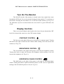
MONITOR (for PST7000/PST7300)
Mechanical Operation
The PST terminal has been designed with a novel support for the monitor.
Beside the usual tilt and swivel mechanism, this terminal has incorporated “slide”
capability so that the monitor position may be fully adjusted without having to use a
swing support arm. At all times the monitor is firmly supported on the display
platform, this gives a stable wobble free image and an absence of mechanical damage,
often associated with the more common swing arm mounting.
MONITOR BODY
MOVEMENT
SWIVEL BASE
MOVEMENT
L4
L3
L3 L4
L2
L2
L1
L1
L0
L0 LP
LP
Fig. 4 - 1 Mechanical operation of the monitor
4-3
PST-7000 series user’s manual – BRIEF INTRODUCTION
Turn On The Monitor
The ON/OFF switch of the monitor is located at the lower right front corner
beneath the CRT bezel. It is a rock switch. Pressing the side marked “I” in will turn on
the monitor. Pressing the side marked “O” in will turn off the monitor (ref. Fig. 4-2).
The indication of power on status besides the screen itself is a green LED above the
switch.
Display Controls
There are in total 4 thumb wheel knobs at the lower left part beneath the CRT
bezel for electronically control over the CRT monitor display.
CONTRAST CONTROL
The first one to the right of this group is the knob for contrast control. Turning
this knob to the right will decrease the contrast whilst turning it left will increase the
contrast (ref. Fig. 4-2).
BRIGHTNESS CONTROL
The second knob to the right in this group is the knob for brightness control.
Turning this knob to right will decrease the brightness whilst turning it left will
increase the brightness (ref. Fig. 4-2).
HORIZONTAL PHASE CONTROL
The third knob to the right in this group is the knob for horizontal phase
control. Turning this knob to right will shift the picture on CRT screen to right whilst
turning it left will shift the picture to left (ref. Fig. 4-2).
4-4
PST-7000 series user’s manual – USING THE PST SYSTEM
VERTICAL SIZE CONTROL
The leftmost knob in this group is the knob for vertical size control. Turning
this knob to right will decrease the height of the picture whilst turning it left will
increase the height (ref. Fig. 4-2).
CONTROL KNOBS
VERTICAL
SIZE
HORIZONTAL
PHASE
BRIGHTNESS
CONTRAST
MONITOR POWER SWITCH
Fig. 4 - 2 Controls of the monitor
Display Utility Driver
The end user of the PST terminals is not supposed to install the utility drivers
personally. If an optional preloaded OS is ordered, the required driver will be already
installed in the preloaded OS. However, the driver will always be available over our
web site: http://www/posiflex.com.tw
4-5
PST-7000 series user’s manual – BRIEF INTRODUCTION
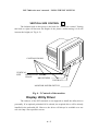
LCD (for PST7050/PST7350)
Mechanical Operation
The 12.1” LCD color display is a 800 x 600 LCD display which may be
positioned to give the operator the clearest view. The display may be lifted from the
horizontal to the upright position and rotated through a total of 75° (left 45° max.,
right 30° max.) and slid sidways for a total distance of 72 mm, care should be
exercised not to attempt to exceed these limits (ref. Fig. 4-3).
L3 L4
L2
L1
L0 LP
Fig. 4 - 3 Mechanical operation of LCD display
4-6
PST-7000 series user’s manual – USING THE PST SYSTEM
Display Utility Driver
Please refer to the “Display Utility Driver” section for monitor on page 4-5.
CUSTOMER DISPLAY
The PST7000 series is available with following possible customer display
options:
• PD-2101/2201
A two line by twenty character vacuum fluorescent
display (VFD) with commas, periods and second row underlines.
• PD-7001/7101
A thirty two by one hundred and sixty dot matrix LCD
array organized to display a wide range of characters in many organizations
with up to four lines by twenty six characters.
These customer displays all possess a delicate and modern industrial design
not only in its appearance and display but also with user friendly mechanical features.
Versatile Mechanical Maneuverability
All the customer displays of the PST series provide a delicate design to
support versatile mechanical maneuverability. The height can be easily and safely
adjusted. The display frame can be rotated horizontally and slid sideways. The display
frame can also be tilted up/down to give different view angles.
To adjust the height, please just pull out the release button, adjust the display
to the height required, and then release the button switch. Twist or move the innerpole a little bit so that the latching track on the inner-pole matches up with the release
button
The display frame can be rotated horizontally for almost 360 degrees to face
any direction required for a point of sale. However, an internal stopper is provided to
limit the rotation within 360 degrees in order to avoid damaging the internal cable by
multi-turn twisting.
4-7
PST-7000 series user’s manual – BRIEF INTRODUCTION
To accommodate the height of most customers, PD-2101/2201 and PD-7001
provide 2 different view angles ---14.5° and 30°.
Posiflex customer displays PD-2101/2201 and PD-7001 provide in particular a
horizontal sliding mechanism for the display frame. The display frame of PD-2101
/2201 and PD-7001 can be slid horizontally from leftmost side to rightmost side, and
vice versa. Total sliding distance is 100mm.
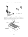
PROGRAMMABLE KEYBOARD
The programmable keyboard in PST7000 series is a sophisticated yet easy and
convenient to use computer sub-system in its own right and is designed to make a
POS software application as flexible and ergonomic as possible. The standard for
PST7000/7050 on this aspect is a 8 x 14 matrixed keyboard coded as KB112. The
keyboard for PST7300/7350 is coded as KB136 which provides at the lower part a
keyboard layout resembling the standard PC keyboard of each country. The following
illustrates the standard KB112. two keyboards share most features in common.
4-8
PST-7000 series user’s manual – USING THE PST SYSTEM
Basic Functions
In essence a programmable keyboard allows any sequence of letters, numbers
and other control functions to be assigned to a particular key. When that key is
pressed the keyboard issues key codes exactly as if the sequence had been typed at a
standard QWERTY computer keyboard. Any key position may be programmed with
any sequence, and the entire keyboard set of key sequences may be uploaded to and
downloaded from the host computer file system.
Furthermore, this programmable keyboard supports a lot of advanced
functions such as keyboard security lock-off, multi-page, multi-level, answer-back,
speed control of output, time control on output hold, software switch off and so on.
These advanced functions are illustrated in the “special features” section. There is no
size restriction other then up to 255 characters per key and up to 8KB total memory
size for all the key definitions.
Structure
To the left of the keyboard frame is the MSR section, beneath the front edge of
the keyboard frame is a front door in which, there is a connector for external keyboard
connection. These two ports share the same port as the programmable keyboard.
When the programmable keyboard locks off the keyboard port, any input from these
two devices is also blocked off to insure the system security.
At the top right corner of the keyboard frame there is a 6 position key-lock.
This electronic key supports the security lock off, answer back and the multi-page
function that expands the programming ability of KB112 to 5 x 112 (560 in total)
possible key definitions, and KB136 to 5 x 51 + 2 (257 in total).
Within the major portion of the keyboard frame is a 8 by 14 matrix allowing in
total 112 positions for the programmable keys in KB112. In KB136 this area is further
divided into 2 parts. The upper part is 3 by 17 matrix parogrammable keys and the
lower part works like conventional keyboard with 2 embedded page independent
programmable keys. The key layout of programmable keys may present versatile
pattern through use of single key, double key, quad key and blank key. For example,
use of blank keys may separate the whole area into several clusters for the
convenience of application. Use of double key or quad key giving a larger surface for
4-9
PST-7000 series user’s manual – BRIEF INTRODUCTION
certain key may ease the operation in pressing key. The programmable keyboard is
delivered with the key tops of single, double and quad keys mounted whilst their
transparent key caps are in the accessory box. The user needs to place the legend
labels and the transparent key caps over each key tops to protect the labels according
to the instructions given in the previous part of this manual. However, from time to
time the user may still need to use the key clip to remove key caps for changing the
legend labels once the key definitions may be updated (ref. Fig. 4-5).
KEY CLIP
6 position key
TRANSPARENT KEY CAP
LEGEND LABEL
KEYBOARD
FRAME
L3 L4
L2
L1
L0 LP
MSR section
Front door for external
connection of a standard
computer keyboard
Fig. 4 - 5 Key structure
4 - 10
PST-7000 series user’s manual – USING THE PST SYSTEM
6 Position Key-Lock
This keyboard has a six position key switch which itself may be programmed
so that as the position is changed with a key so the key switch reports its own position
(adjustable inter position time delays are programmed in). Further more, an enquiry
code from the host will cause the key switch to report its current position.
This 6 position key switch effectively provides a multi-layer capability to the
keyboard in that each position of the key can define separate key sequence for each
key. This gives rise to the concept of pages, so that the KB112 can be said to have 5
pages of 112 key definitions per page, this means that there are 560 possible key
definitions, and KB136 has 5 pages of 51 key definitions per page plus the 2 page
independent programmable keys.
There are 4 keys supplied with each keyboard and the lock is so designed that
certain keys may only be turned to certain positions. This architecture is similar to that
found in many high end ECR systems, so it is not surprising that the naming
conventions have been borrowed as well.
The keys are named: PRG, REG, Z, GT.
The switch positions are named: LP, LCK, L1, L2, L3, L4. Among these, the
position LCK marked as “ ”
The available positions for each key type are listed in the table below of this
page and are graphically illustrated in Fig. 4-6.
ü= access
û= no access
PRG
REG
Z
GT
LP
ü
û
û
û
LCK
ü
ü
ü
ü
L1
ü
ü
ü
ü
L2
ü
ü
ü
ü
L3
ü
û
ü
ü
L4
û
û
û
ü
4 - 11
PST-7000 series user’s manual – BRIEF INTRODUCTION
GT
Z
PRG
REG
L2
L1
L3
L4
LP
STAND BY
POWER
Fig. 4 - 6 Range for each key type
The position LCK is designed to provide a “Security Lock-Off” function.
Keys may only be removed from positions LCK and L1.. (ref. Fig. 4-7)
POWER ON LED
L3 L4
L2
L1
L0 LP
STAND-BY LED
Fig. 4 - 7 Extraction of key from electronic lock
4 - 12
PST-7000 series user’s manual – USING THE PST SYSTEM
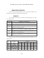
Application Example
The effect of this programmability is to give a tremendous flexibility to any
keyboard layout requirement with any application package.
EXAMPLE 1
As an example the following is a possible key and position usage for a multilevel organized store:
POSITION
LP
LCK
POSSIBLE APPLICATION
To be used for key programming or system maintenance functions
All devices sharing the keyboard port are disabled.
L1
Keyboard programmed for check out function, so that each
operation is a single key operation.
L2
Keyboard to be programmed for support functions, printer paper
change, product code checking, shift change consolidation etc.
L3
Keyboard to be programmed for special supervisory tasks, such as
inventory control, return sales etc.
L4
Keyboard to be programmed for senior management purposes, such
as passwords, material costs etc.
While the 4 types of keys are kept by different positions of employee as in the
following table:
Key
Job Title of
Access to
Type
Holder
LCK
L1
L2
L3
L4
LP
REG
Cashier
ü
ü
ü
û
û
û
Z
Supervisor
ü
ü
ü
ü
û
û
GT
Senior Manager
ü
ü
ü
ü
ü
û
PRG
Programmer
ü
ü
ü
ü
û
ü
4 - 13
PST-7000 series user’s manual – BRIEF INTRODUCTION
EXAMPLE 2
For a multi-function store, such as a restaurant serving for all of breakfast,
lunch, dinner and late snack, each meal requires very different menu; or a department
store that is seeking for a standardized facility throughout its various departments
each requires many items of merchandise, the multi-page capability of this keyboard
can play the crusader. Simply program each page of the keyboard for each meal or
each department. This PST programmable keyboard then serves for different
application as the 6 position key is turned to different position, yet the facility remains
unified.
FURTHER IDEAS
The answer back function of this keyboard can be utilized to show some
welcome sign on the customer display or force the system into an instant sleep mode
when the cashier has to leave the post for a short period and turn the switch to LCK
position.
Combining the answer back function of the keyboard with the software
shutdown capability of the terminal, the answer back code can be programmed to
some software command that will instruct the application program to start a
termination process and then send the shutdown command codes to the system. In this
way, the key position LP can be used as the software safeguarded power off switch.
All the above are only some examples of the powerful combination of key
programming and key access management that is possible with this keyboard. Further
functionality and sophistication can be applied with multiple level keys and other
capability of this keyboard. All of this may be accomplished without any additional
lines of application program code and without introducing any TSR or .dll executables
into the system.
4 - 14
PST-7000 series user’s manual – USING THE PST SYSTEM
Special Features
SECURITY LOCK OFF
As mentioned elsewhere, when the 6 position electronic key-lock is switched
to position “LCK”, the whole keyboard port is disabled for security purpose. This
works just like a hardware disconnection of the keyboard including all other devices
sharing this port such as the MSR option or any other either internally or externally
connected DCI device. This ability provides security when the cashier has to leave the
post for a short period but the station must not be turned down.
MULTI-PAGE PROGRAMMING
As explained before, the key definition string of each key can be altered by the
position of the 6 position electronic key-lock. This provides a fast turn over of the key
definitions just by turning the 6 position key.
MULTI-LEVEL PROGRAMMING
Most people could have some idea about the “combination key” from the
standard computer keyboard using “SHIFT”, “CTRL” or “ALT” keys to give other
keys different interpretation or presentation. The PST keyboard doubtlessly possesses
such ability. The PST keyboard even supports the “multi-level programming” which
is a more advanced kind of combination key. In using the multi-level programmed
keys, there are certain key(s) defined as the level selector (called as the marker).
When used in combination, the content of the level corresponding to the level selector
(marker) will be issued. In this structure, the PST keyboard provides much more than
112 varieties of the character strings to be issued within one page.
ANSWER BACK
The 6 position key switch of the PST programmable keyboard may be
programmed so that as the position is changed with a key so the key switch reports its
own position (adjustable inter position time delays are programmed in). Further more,
4 - 15
PST-7000 series user’s manual – BRIEF INTRODUCTION
an enquiry code from the host will cause the key switch to report its current position
to the application program.
SPEED CONTROL OF OUTPUT
The PST programmable keyboard is capable of adjusting its own speed in
issuing the key definitions when the key is pressed. This feature is important for
certain application or some system environment that too fast output from the keyboard
may cause some difficulties. This feature is referred to as “inter-character delay” in
the programming language and is adjustable in unit of millisecond.
TIME CONTROL ON OUTPUT HOLD
From time to time, there can be need for the keyboard to hold on its output for
a certain period of time before next data to be issued to the system. The PST keyboard
is capable of programming a hold on time in unit of second. This feature is called as
the programmed time delay in the programming language.
SOFTWARE SWITCH OFF
As the PST7000 series is designed to support the software shutdown
command, the answer back function of position LP can be programmed to some
software command that will instruct the application program to start a termination
process and then send the shutdown command codes to the system. In this way, the
key position LP can be used as the software safeguarded power off switch. This
feature is designed for the sake of data preservation.
CONVENIENCE IN PROGRAMMING
The PST programmable keyboard is supported with various methods for
programming its key definitions. However, the details of programming can only be
obtainable in the optional Technical Manual. The followings are those methods that
make programming the PST keyboard an easy job:
4 - 16
PST-7000 series user’s manual – USING THE PST SYSTEM
•
RWM.EXE – This is a straight through programming utility used under DOS
environment.
• KBM.EXE – This is a detail programming utility applicable under DOS,
WINDOWS 3.1, WINDOWS95 and so on.
• HOT KEY PROGRAMMING – This is the most convenient (maybe less
efficiently) programming method applicable under any environment. This is also
the method most possibly used by the end user for instant content update. This will
be further discussed in next section.
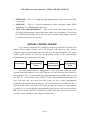
INSTANT CONTENT UPDATE
If you want to update the key definition of any key in the PST keyboard, this
instant content update feature serves the purpose best. However, this method
programs only the normal displayable characters for the key definitions. The instant
content update utilizes the Hot Key programming ability of the programmable
keyboard that can be arranged in four steps:
Preparation
Enter “hot key
programming”
mode
Input the
content to be
programmed
Exit “hot key
programming”
mode
The preparation requires a standard PC or PS/2 keyboard connected to the
external keyboard connector of the PST7000 series in the front door area locked by
the mechanical key. To enter the Hot Key programming mode, the left “Alt” key and
the “PRT SC” (“Print Screen”) key on the PC or PS-2 keyboard must be pressed at the
same time and after two beeps from the system, the key on the programmable
keyboard to be updated must be pressed. The user should then use either the PC or
PS/2 keyboard or the connected CCD scanner to input the content to be programmed
for that key. To exit the Hot Key programming mode, the user has to press both the
left “Alt” key and the “PRT SC” (Print Screen) again. The system gives one beep here
to notify a successful input, three beeps for input failure.
4 - 17
PST-7000 series user’s manual – BRIEF INTRODUCTION
Preloaded Key Definitions
This keyboard is preloaded with a particular pattern on the page LP before it is
delivered. Please refer to the print out on next page for the key definition of each
location of this preloaded pattern for KB112 and the page next for KB136. The
purpose of this preloaded page is to serve the software designer so that you won’t
have to connect an external PC keyboard when you start to program the PST
keyboard. This preloaded pattern may be discarded in accordance of the application
system. However, it is recommended to preserve this pattern before discarding it.
To preserve this preloaded pattern into a computer file for later use, you
should refer to the “readme” file on the attached diskette in the accessory box. Then
you should issue the following command from the subdirectory where you keep your
keyboard driver to create the file, for example: “KB112.TPL”, to store the preloaded
pattern:
rwm kb112.tpl -r
4 - 18
PST-7000 series user’s manual – USING THE PST SYSTEM
Print
Screen
Scroll
Lock
Pause
Ins
Home
PgUp
→
Del
End
PgDn
(
9
)
0
_
-
+
=
←
I
7
8
9
Q
R
4
5
6
X
Y
Z
1
2
3
Space
Alt
Ctrl
0
00
.
+
−
∗
Esc
F1
F2
F3
F4
F5
F6
Tab
F7
F8
F9
F10
F11
F12
{
[
}
]
|
\
:
;
”
’
<
,
>
.
?
/
←
↓
~
`
!
1
@
2
#
3
$
4
%
5
^
6
&
7
*
8
A
B
C
D
E
F
G
H
J
K
L
M
N
O
P
Cap
S
T
U
V
W
Shift
Ctrl
Alt
Space
Space
Space
/
↑
ÿ
PRINT - OUT OF PRELOADED KEY DEFINITIONS FOR PAGE LP IN KB112
4 - 19
Enter
4 - 20
Insert
Esc
`
Tab
F1
F2
F4
F5
!
@
#
$
%
1
2
3
4
5
Q
Caps
Lock
W
A
E
S
Z
ñ Shift
Ctrl
F3
R
D
X
C
6
T
F
F6
Y
G
V
F7
Delete End
PgDn
F9
F11
Alt
Print
Scroll
Screen Lock
F12
*
(
)
_
+
7
7
8
9
0
-
=
Home
U
I
J
N
O
K
P
L
{
}
¦
[
]
\
:
"
;
'
M
Enter
?
,
ÿ
F10
&
H
B
F8
Home PgUp
.
Alt
ñShift
/
ÿ
Pause
Num
Lock
8
9
PgUp
4
5
6
1
2
3
End
0
PgDn
00
Ins
Ctrl
PRINT - OUT OF PRELOADED KEY DEFINITIONS FOR PAGE LP IN KB136
PST-7000 series user’s manual – USING THE PST SYSTEM
.
Del
PST-7000 series user’s manual – USING THE PST SYSTEM
MSR – MAGNETIC STRIPE READER
The Magnetic Stripe Reader (MSR) slot is located at the left side of the
Programmable Keyboard if the MSR option is ordered when the PST system is
equipped with the standard 112 key programmable keyboard. There are two choices
of the reader types -- dual tracks and triple tracks separately.
For card reading, be sure to insert the card to the bottom with magnetic stripe
facing right. The movement of the card can be either inserting the card from the top
surface then sliding the card down out of the slot, or sliding the card upward from the
lower side of the slot till it reaches the top end (ref. Fig. 4-8) as long as the card is a
standard one. A non-standard card recorded without complete degaussing prior to
recovery may accept only one direction in card reading.
The MSR indicator located near the MSR slot will light up in green when the
MSR is ready to read, blink during reading, and then give a green light if the reading
is successful. The MSR indicator will turn to be red if the reading fails due to
improper sliding or poor magnetic intensity of the magnetic stripe, the MSR indicator
will then turn back to green when the MSR is again ready to read.
MSR SLOT
MSR INDICATOR
READER HEAD POSITION MARK
STAND-BY INDICATOR
POWER ON INDICATOR
Fig. 4 - 8 Reading magnetic stripe cards
4 - 21
PST-7000 series user’s manual – BRIEF INTRODUCTION
LED INDICATORS
Besides the LED on MSR unit there are another two LED’s on the main unit
below the 6-position electronic key on the programmable keyboard (ref. Fig. 4-8). The
right hand green LED, called as the power LED, and the left hand orange LED, called
as the Standby LED, together exhibit several different system status depending on
whether or not an UPS battery is fitted.
(a) Without an UPS battery the power LED lights to show that the system is turned
ON under presence of AC power. The standby LED indicates that AC power is
available when the system is powered off.
(b) With a UPS battery fitted:
1. The standby LED gives a steady illumination to indicate the presence of
AC power when the system is powered off. The system cannot be turned
on if the AC power fails, even when the battery is fully charged. The
power LED goes ON and the standby LED goes OFF when the system is
powered up.
2. During periods of AC power failure with the system turned on, the power
LED flashes to indicate that the system is running on battery power.
3. The power LED is turned OFF and the standby LED flashes rather fast as
the UPS battery approaches a discharged condition to remind the operator
that power will soon finish. In few seconds, the whole system will soon be
automatically turned off and both LED will be OFF.
4. In case the AC power resumes during the usage of the battery, the flashing
LED will keep on flashing for few seconds till the AC supply is
considered stable.
4 - 22
PST-7000 series user’s manual – USING THE PST SYSTEM
FRONT DOOR
At the front of the programmable keyboard there is a door with a mechanical
lock to the right of it. Turning the key clockwise will cause the front door to open a
small amount where it is held against a catch, the door may be fully opened by hand.
When the key is returned to its original position and the door is pushed back, the door
will be locked into position once more. This lock mechanism also physically locks the
programmable keyboard subassembly housing to the chassis of the main unit, which
prevents unauthorized access to the internal electronics. There are the external PC
keyboard connector, main power ON/OFF push switch and the 1.44MB 3.5” Floppy
Disk Drive (FDD) behind the door.
EXTERNAL PC KEYBOARD
From time to time it will be necessary or more convenient to use a standard PC
keyboard. This may be to reprogram the PST keyboard key definitions, or to alter
some aspects of either the DOS operating system or the application program. The PC
keyboard may be plugged into the 5 pin DIN socket behind the front door.
This socket may also be used to trial a new device that is required to be daisy
chained to the keyboard port (e.g. a table scanner). Please keep in mind the previously
mentioned limit of 5 devices.
3.5” FDD
This port is a standard PC device, it accepts any 3.5” floppy diskette formatted
to 1.44 MB, 720 KB or 1.2 MB IBM (Japan) PC standard which emulates a 5¼ inch
HD FD but on a 3½ inch physical disk.
4 - 23
PST-7000 series user’s manual – BRIEF INTRODUCTION
POWER ON/OFF CONTROL
The PST7000 terminal implements electronic power control, such that the
main power to the system may be controlled by five methods:
1. Front mounted external power ON switch
2. Internal power ON/OFF push switch
3. Software OFF switch
4. Preset power ON control
5. Emergency power OFF
Switching from OFF to ON requires a normal supply of the AC power.
External Power On Switch
This button is located on the lower right hand front edge of the keyboard and
can be used to turn on the system only. That means, when this switch is accidentally
pressed during system turned on, the system just remains on and not affected.
This switch can also be programmed to an ON/OFF switch (with default as
ON only) through software command.
Power On/Off Push Switch
This is the switch behind the front door. This switch is a simple momentary
action switch, which activates a toggle action in the electronics of the power supply
circuits. Its function is to toggle the power supply on and off. If the terminal is
powered off, then pressing the button simply powers on the unit. If the unit is powered
on then pressing the button will power off the terminal.
Note: Powering off the unit in this way is instantaneous and must be undertaken
with care to prevent any loss of data.
Software Off Switch
The system may also be shut down under software control, details of which are
beyond the scope of this user manual - for more details contact your dealers.
However, it is the most recommended way to turn off the PST7000 series. Because
the application program can then be able to control and secure against any possibility
of data loss.
4 - 24
PST-7000 series user’s manual – USING THE PST SYSTEM
Preset Power On Control
The system may also be turned on according to some predetermined parameter
such as Modem Ring Up and Alarm Clock Wake Up or LAN Wake Up.
To utilize Modem Ring Up or Alarm Clock Wake Up function, the user should
enter the CMOS setup by pressing “DEL” key at system boot up, choose for
“INTEGRATED PERIPHERALS” and make the “Ring Power Up Control” enabled
for Modem Ring Up or select the “Power Up by Alarm” for Alarm Clock Wake Up.
Save the configuration and exit the CMOS setup program. The Preset Power On
Control will then be ready. To excercise the LAN Wake Up function, the condition
for waking the system up must be defined through use of a specific software before
the system shut down.
When the PST7000 system is turned off after a successful boot up, the defined
preset power on functions will keep monitoring for the preset conditions. When a
Modem call is received, the system will be turned on and start to work according to
the security conditions as the application program defines if the Ring Power Up
Control is enabled. If the Power Up by Alarm is enabled, the PST7000 system will be
turned on at the defined time (Hour:Minute:Second) of the preset day of week, day of
month , month of year or even every day if these items are not defined.
Please note that if the PST7000 system is improperly turned off before a
complete boot up procedure, the above preset power on control functions will be
disabled until next turning off after a complete boot up.
Emergency Power Off
In case of serious system halt due to any reason, the system could fail to be
powered off through normal means. Please apply Emergency Power Off method only
on such occasion. Press and hold the Power ON/OFF Switch or the External Power
ON Switch after it is programmed as ON/OFF switch. The system will be powered off
within 10 seconds in this way. Release the switch after the system powered off. If
there appears to give a special coded beep tone in the pattern “short, long, short, long,
short” prior to the system power off in this process, please remove the AC power and
wait for few minutes to allow the hardware registers to reset (If there is no such beep,
AC removal is not required). Then you may restart the system and take remedial
action against the precious failure.
4 - 25
PST-7000 series user’s manual – BRIEF INTRODUCTION
REAR ROOM
The terminal has a rear room that covers the signal and power connector area
and is designed to provide a tidy and secure termination for all cables into and out of
the terminal. Cables may be secured by attaching them with cable ties to the lattice
base of the compartment.
Access to the rear room is gained by releasing the rear door latches. These are
located under the lower edge of the door at either side of the door. They may be
located by “feeling the ridges” on the latch, sliding both latches to the centre of the
door will release the door. These latches are intentionally stiff.
PRINTER
One of the major design features of the PST terminals is the ability to
accommodate a very large range of printers. The terminal provides a printer platform
where the printer can be mounted (use the Velcro strips in the accessories kit for
fixation aid), and also provides a regulated 24 volt dc power line to power the printer.
The terminal can accommodate both parallel and serial interfaces.
Please consult the printer user manual before assembling and connecting any
printers to the terminal.
USB
There are two standard USB female connectors in the rear room. Both support
the Universal Serial Bus Specification version 1.1. The application of USB is ever
growing with the new Operation Systems introduced at the conjunction of 20th and
21st centuries.
BUILT-IN UPS WITH BATTERY
The built-in UPS battery option, if purchased, works without need for much
care. In case of power failure from the AC inlet, the PST system beeps for alarm and
automatically switches to battery power smoothly. The equipped battery, when fully
charged, will support the system to operate for at least 5 minutes subject to the load
such as printing. The coverage of this UPS support includes the PST system itself, the
customer display port, the cashier display port, the +24 V DC supply, the direct driven
4 - 26
PST-7000 series user’s manual – USING THE PST SYSTEM
CR port, the KB wedge connected device and the serial ports if the DC supply is
enabled. However, the devices using the AC power is not supported by the UPS such
as the optional 10” color monitor. Should the user want to replace the battery or
reconnect to another larger battery, he/she may refer to Fig. 3-12 and press down the
end with arrow of the battery cover to open the battery cover by pushing it toward the
rear room.
The battery is maintenance free and is leakproof constructed. The battery
compartment of the PST system also provides very good protection as long as the
ambient temperature remains below 30°C and the ventilation of the PST system is not
blocked. However, should any accident happen and the sulfuric acid from the battery
is spilled on skin or clothing, wash immediately with water. If the acid comes in
contact with eyes, rinse eyes with large amount of water and immediately see a
doctor.
WARNING:
ONLY CONNECT/DISCONNECT THE BATTERY WHEN SYSTEM
POWERED OFF WITH THE MAINS POWER REMOVED.
DISPOSE OF THE BATTERY CORRECTLY. DO NOT EXPOSE TO
HEAT.
IF THERE ARE ANY SIGNS OF OVER CHARGING OR LEAKAGE
OF ELECTROLYTE PLEASE CONTACT YOUR DEALER IMMEDIATELY
A larger external battery may be connected to give an extended operation.
Please see your dealer about this capability.
DISCLAIMER
The manufacturer of the integrated POS terminal system makes no
representations or warranties, either expressed or implied, by or with respect to
anything in this manual, and shall not be liable for any implied warranties of
fitness for a particular purpose or for any indirect, special or consequential
damages. Information in this document is subject to change without notice and
does not represent a commitment on behalf of the manufacturer.
4 - 27