1
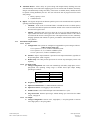
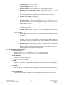
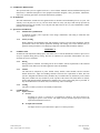
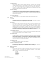
LIEBERT Nfinity UPS
GUIDE SPECIFICATIONS
for a 4 to 20kVA (208/120V or 240/120V)
Single-Phase Uninterruptible Power Supply System
1.0 GENERAL
1.1 SUMMARY
This specification describes the Nfinity UPS, a modular uninterruptible power supply system for workstation,
server, network, telecom and other sensitive electronic equipment applications. It defines the electrical and
mechanical characteristics and requirements for a continuous-duty single-phase, solid-state, uninterruptible
power supply system. The uninterruptible power supply system, hereafter referred to as the UPS, will provide
high-quality AC power.
1.2 STANDARDS
The UPS is designed in accordance with the applicable sections of the current revision of the following
documents. Where a conflict arises between these documents and statements made herein, the statements in this
specification shall govern.
UL Standard 1778
IEEE C62.41, Category A & B
CSA 22.2, No. 107.1
FCC Part 15, Sub Part B, Class A
National Electrical Code (NFPA 70)
IEC 62040-3 (formerly NEMA PE-l)
1.3 SYSTEM DESCRIPTION
1.3.1
General
The Nfinity UPS system consists of the appropriate number of modules for capacity and/or
redundancy. All modules are to be operating simultaneously and sharing the load. In a non-redundant
system, all the modules making up the UPS are required to supply the full rated load. If a power or
control module malfunctions, the load will transfer automatically to the bypass line. If a battery
module malfunctions, it will automatically isolate itself from the system. For redundant operation, the
UPS will have one or more modules than what is required to supply the full rated load. The
malfunction of one of the modules will cause that module to be isolated from the system and the
remaining module(s) will continue to carry the load. Replacement of a module is capable without
disturbance to the connected load (Hot-swappable/User Replaceable).
1.3.2
Modes of Operation
The UPS is designed to operate as a true on-line system:
A. Normal - The critical AC load is continuously supplied by the UPS inverter. The input converter
derives power from a utility AC source and supplies DC power to the inverter. The battery
charger maintains a float-charge on the battery.
B. Back-up - Upon failure of utility AC power the critical AC load is supplied by the inverter. In this
mode the inverter is powered from the battery. There is no interruption in power to the critical
load upon failure or restoration of the utility AC source.
C. Recharge - Upon restoration of utility AC power, the input converter will automatically restart
and resume supplying power to the inverter. The battery charger will resume recharge of the
battery.
Liebert Nfinity UPS
4kVA –20kVA (208/120 or 240/120)
1
Guide Specification
4/03 Rev 2
SL-23956
D. Automatic Restart - After a utility AC power outage and complete battery discharge, the UPS
will automatically restart and resume supplying power to the critical load. In addition, the battery
charger will automatically recharge the battery. This feature is enabled (factory default) and will
be capable of being disabled by the user. The user will also be able to program two auto restart
delay settings
1.
2.
Battery capacity % level
Countdown timer
E. Bypass - The bypass will provide an alternate path for power to the critical load and is capable of
operating in the following manner:
1.3.3
1.
Automatic - In the event of an internal failure or should the inverter overload capacity
be exceeded, the UPS will perform an automatic transfer of the critical AC load from the
inverter to the bypass source.
2.
Manual - Should the UPS need to be taken out of service for limited maintenance or
repair, manual activation of the bypass will cause an immediate transfer of the critical
AC load from the inverter to the bypass source. The input converter, inverter, and battery
charging operations will continue to operate, provided the control enable switch is in the
“On” position.
Performance Requirements
1.3.3.1 System
A. Configuration: UPS systems are configured or upgradeable to power ratings as follows:
12 Bay Frame Systems only
4 kVA system to 8, 12, 16, or 20kVA redundant system.
8 kVA system to 12, 16, or 20kVA redundant system.
12 kVA system to 16, or 20kVA redundant system.
B. Isolation: Input to output isolation is provided via the output transformer, regardless of
the operating mode. (UPS or bypass)
C. Remote Stop: The UPS provides provisions for remote stop (Emergency Power Off)
capability.
1.3.3.2 AC Input to UPS
A. Voltage Configuration: 208 or 240 VAC nominal (tap selectable), single-phase, 2-wireplus-ground. The operating voltage range is variable based upon output loading
percentages as follows:
% UPS Load
80 – 100%
60 – 80%
30 – 60%
0 – 30%
Input Voltage
170 VAC
144 VAC
127 VAC
110 VAC
B. Frequency: 40 to 70 Hz.
C. Input Current Distortion: 5% THD maximum at full load.
D. Input Power Factor: 0.98 lagging at 100% rated load.
E. Inrush Current: 150% of full load input current maximum for 3 cycles.
F. Surge Protection: Sustains input surges without damage per criteria listed in IEEE
C62.41, Category B.
1.3.3.3 AC Output
A. Voltage Configuration: 240/120 VAC, single-phase, 3 wire-plus-ground or 208/120
VAC single phase, 3 wire plus ground.
Liebert Nfinity UPS
4kVA –20kVA (208/120 or 240/120)
2
Guide Specification
4/03 Rev 2
SL-23956
B. Voltage Regulation: +/- 3% steady state.
C. Frequency Regulation: 60 Hz, +/- 0.5%.
D. Frequency Slew Rate: field selectable from 0.5 to 5.0 Hz maximum per second.
E. Bypass Frequency Synchronization Range: field selectable from 0.5 to 5.0 Hz
maximum per second.
F. Voltage Distortion: 3% total harmonic distortion (THD) maximum into a 100% linear
load, 7% THD maximum into a 100% non-linear load with crest factor ratio of 3:1.
G. Load Power Factor Range: 0.5 lagging to 1.
H. Output Power Rating: Rated kVA at: 0.7 lagging power factor.
I.
Overload Capability: >100% - 110% indefinitely, 111% -150% for 10 seconds, 151% 200% for 0.25 seconds. The load will be transferred to bypass when any of the above
conditions are exceeded. >201% for min. 2 cycles, then shut down of UPS. Immediate
shutdown into a short circuit.
J.
Voltage Transient Response: +/- 7% maximum for any load step up to and including
100% of the UPS rating.
K. Transient Recovery Time: To within 1% of steady state output voltage within 96
milliseconds.
1.3.3.4 Batteries
A. Internal Battery: The battery consists of flame retardant, valve regulated, lead acid
cells. The UPS is suitable for installation inside a computer room per requirements of UL
Standard 1778.
B. Reserve Time: The UPS contains internal battery system to provide a reserve time of 7
minutes at 100% load with an equal number of power and battery modules fitted. The
UPS includes provisions to fit additional battery modules internally if space permits. The
UPS also interfaces with an external battery cabinet to extend reserve time capabilities.
C. Battery Recharge: To prolong battery life, the UPS includes temperature-compensated
battery charging. When equal number of power modules and battery modules are fitted
the battery charger is able to recharge the internal batteries to 90% charge in six hours at
nominal input voltage and nominal ambient temperature.
1.4 ENVIRONMENTAL CONDITIONS
A. Ambient Temperature
Operating: UPS 0° C to +40° C; battery 20° C to 25° C for optimum performance.
Storage: UPS –20° C to +60° C; battery –20° C to 25° C for maximum 6 months.
B. Relative Humidity
Operating: 5 to 95% non-condensing.
Storage: 5 to 95% non-condensing.
C. Altitude
Operating: To 10,000 feet. Derating/reduced operating temperature range required for higher altitudes.
Storage: To 30,000 feet.
D. Audible Noise
Noise generated by the UPS during normal operation does not exceed 62 dBA measured at three feet
(one meter) from the surface of the UPS.
E. Electrostatic Discharge
The UPS is able to withstand a minimum 15 kV without damage and will not affect the critical load.
Liebert Nfinity UPS
4kVA –20kVA (208/120 or 240/120)
3
Guide Specification
4/03 Rev 2
SL-23956
1.5 USER DOCUMENTATION
The specified UPS system is supplied with one (1) user's manual. Manuals include installation drawings and
instructions, a functional description of the equipment with block diagrams, safety precautions, illustrations,
step by step operating procedures, and routine maintenance guidelines.
1.6 WARRANTY
The UPS manufacturer warrants the UPS against defects in materials and workmanship for two (2) years. The
warranty covers all parts for two (2) years and onsite labor for ninety (90) days. With start-up provided by
Liebert Global Services, the warranty covers all parts and onsite labor for two (2) years. Maintenance contract
packages are also available.
1.7 QUALITY ASSURANCE
1.7.1
Manufacturer Qualifications
A minimum of thirty year's experience in the design, manufacture, and testing of solid-state UPS
systems is required.
1.7.2
Factory Testing
Before shipment, the manufacturer fully and completely tests the system to assure compliance with the
specification. These tests include operational discharge and recharge tests on the internal battery to
guarantee rated performance. The UPS ships completely assembled and all modules installed.
2.0 PRODUCT
2.1
FABRICATION
All materials and components making up the UPS will be new, of current manufacture, and not in prior service
except as required during factory testing. The UPS is constructed of replaceable subassemblies. All active
electronic devices are solid-state.
2.1.2
Wiring
Wiring practices, materials, and coding will be in accordance with the requirements of the National
Electrical Code (NFPA 70) and other applicable codes and standards.
2.1.3
Cabinet
The UPS unit is comprised of: power module, battery module, control module, and user interface
module housed in a single free-standing enclosure and meets the requirements of IP20. The UPS
system is designed such that the battery modules may be installed into any module bay in the cabinet
and power modules into any module bay in the top half of the cabinet. The UPS cabinet is cleaned,
primed, and painted with the manufacturer's standard color. Casters and leveling feet are provided. 12
bay cabinet dimension is 20 inches wide, 28 inches deep, and 53 inches high.
2.1.4
2.2
Cooling
The UPS is cooled by forced air via internally mounted fans.
COMPONENTS
2.2.1
Input Converter
A. General
Incoming AC power is converted to a regulated DC output by the input converter for
supplying DC power to the inverter. The input converter provides input power factor and
input current distortion correction.
B. AC Input Current Limit
The input converter is provided with AC input over current protection.
Liebert Nfinity UPS
4kVA –20kVA (208/120 or 240/120)
4
Guide Specification
4/03 Rev 2
SL-23956
C. Input Protection
The UPS has built-in protection against undervoltage, overcurrent, and overvoltage
conditions including low-energy surges introduced on the primary AC source and the bypass
source. The UPS can sustain input surges without damage per criteria listed in IEEE C62.41,
Category A & B. The UPS cabinet contains an input breaker sized to supply full 20kVA rated
load and to recharge the battery at the same time.
D. Battery Recharge
To prolong battery life, the UPS contains temperature-compensated battery charging. When
an equal number of power modules and battery modules are installed the battery charger is
able to recharge the internal batteries to 90% charge in six hours at nominal input voltage and
nominal ambient temperature.
E. Charger Output Filter
The battery charger is a DC power supply to minimize ripple current into the battery.
2.2.2
Inverter
A. General
The inverter converts DC power from the input converter output, or the battery, into precise
regulated sine wave AC power for supporting the critical AC load.
B. Overload
The inverter is capable of supplying current and voltage for overloads exceeding 100% and
up to 200% of full load current. A visual indicator and audible alarm indicates overload
operation. For greater currents or longer time duration, the inverter has electronic currentlimiting protection to prevent damage to components. The inverter is self-protecting against
any magnitude of connected output overload. Inverter control logic senses and disconnects
the inverter from the critical AC load without the requirement to clear protective fuses. The
load will be transferred to bypass when any of the above conditions are exceeded.
C. Maximum Load Alarm
The user can set the alarm point to a value less than 100% rating such that the UPS will alarm
before an overload condition or loss of redundancy is reached.
D. Output Frequency
The output frequency of the inverter is controlled by an oscillator. The oscillator will hold the
inverter output frequency to +/- 0.5% for steady state and transient conditions. The inverter
tracks the bypass continuously, providing the bypass source maintains a frequency within the
user-selected synchronization range. If the bypass source fails to remain within the selected
range, the inverter will revert to the internal oscillator.
E. Output Protection
The UPS inverter employs electronic current limiting.
F. Battery over Discharge Protection
To prevent battery damage from over discharging, the UPS control logic controls the
shutdown voltage set point. This point is dependent on the rate of discharge.
2.2.3
Display and Controls
A. General
The front panel will consist of multiple status LEDs, switches, and a four line by twenty
character LCD display for additional alarm/configuration information. All mimic display
LED‟s are green in color and indicate the following:
AC Input
On Battery
Load On/Off
On Inverter
On Bypass
Liebert Nfinity UPS
4kVA –20kVA (208/120 or 240/120)
5
Guide Specification
4/03 Rev 2
SL-23956
The UPS fault indicator is used with additional indicators and audible alarms to notify the
user that a UPS fault condition has occurred. The color of the fault indicator LED is amber.
Replace Battery Module
Replace Power Module
Replace Control Module
On Bypass
Low Battery
OverTemp Warning
UPS Shutdown
If there is a fault condition, the UPS will attempt to maintain conditioned power to the load,
or at minimum transfer to bypass. There will also be a visual indication on each module
should the module fail and need to be replaced.
In addition to an audible/visual fault signal the UPS also records fault occurrences in a rolling
event log. The event log on the standard unit can record up to 255 occurrences, with the
oldest events discarded first, etc. The user has access to the event log through the LCD
display. Every alarm and/or event recorded in the event log will contain a time and date
stamp.
B. Audible Alarms
The volume of all audible alarms is at least 65dBA at a distance of three feet (one meter). An
audible alarm is used in conjunction with the LED/LCD indication to indicate a change in
UPS status.
The audible alarms enunciate for utility line loss, low battery (while on battery), and all other
alarm conditions. For all alarm conditions, the user must look at the display to determine the
cause of error/alarm. All alarm tones are a continual tone until the condition rectifies itself or
the alarm is silenced. Once silenced, the audible alarm will not sound until a new alarm
condition is present.
C. Alarm Silence Button
In addition to the load On/Off switch, the user interface includes an audible „Alarm Silence‟
switch. If the alarm silence switch is pressed for one second, all current audible alarms will
be disabled. If a new alarm occurs, or a cancelled alarm condition disappears and then reappears, the audible alarm is re-enabled.
D. LCD Display
The LCD display is used to provide information to the user. The display is used to program
ALL information (voltage, frequency, etc.) into the UPS. Any display values that require
time/date will be „year 2000‟ compliant.
2.2.4
Automatic Battery Test
The UPS will initiate an automatic battery testing sequence periodically, at a programmed day and
time of day, selectable by the end user. The user will be able to select the interval of the battery test
and will be able to select 1, 2, 3, 4, or 6 week intervals, or can select to disable the automatic battery
test.
Should a battery failure occur, the battery module will disconnect itself from the critical DC bus and
the UPS will immediately return to normal mode and fault signals (visual, audible, and remote via
serial) will be communicated. No audible or remote (via serial/contact closures) indication of the
battery test is communicated during the duration of the automatic battery test.
The automatic battery test factory default settings are enabled at a two week interval and to occur on
Wednesdays at 0600hours (based on the twenty-four hour clock).
Liebert Nfinity UPS
4kVA –20kVA (208/120 or 240/120)
6
Guide Specification
4/03 Rev 2
SL-23956
2.2.5
Remote Emergency Power Off (REPO)
The remote emergency power off function (REPO) allows the user to disable all UPS outputs in an
emergency situation. The REPO, in order to be flexible, will be able to interface with either normally
open (N.O.) or normally closed (N.C.) systems. The REPO is activated when a pair of „SELV‟
contacts, external to the UPS, are activated. The REPO connection is through a simple terminal block
type connector.
The REPO function will not operate if no system control modules are present in the UPS or if the
manual bypass switch is in the bypass position. The user must supply a means of interfacing with the
REPO circuit to allow disconnecting the UPS input feeder breaker to remove all sources of power to
the UPS and the connected equipment to comply with local wiring codes/regulations.
Regardless of the UPS mode of operation when the REPO is activated, the UPS output will not be reenabled until the following occurs:
REPO contacts are reset (closed if N.C. contacts are used and open if N.O. contacts are used)
Input circuit breaker is closed
Control enable switch is turned on
User interface on/off switch is depressed
2.2.6
Bypass
A. General
A bypass circuit is provided as an integral part of the UPS. The bypass has an overload rating
of 300% rated full load for 10 cycles and 1000% for sub-cycle fault clearing. The bypass
control logic contains an automatic transfer control circuit that senses the status of the
inverter logic signals, and operating and alarm conditions. This control circuit provides a
transfer of the load to the bypass source, without exceeding the transient limits specified
herein, when an overload or malfunction occurs within the UPS.
B. Automatic Transfers
The transfer control logic automatically activates the bypass, transferring the critical AC load
to the bypass source, after the transfer logic senses one of the following conditions:
Inverter overload capacity exceeded
Inverter over temperature
UPS fault condition
For inverter overload conditions, the transfer control logic inhibits an automatic transfer of
the critical load to the bypass source if one of the following conditions exists:
Inverter/Bypass voltage difference exceeding preset limits (±15 % of nominal)
Bypass frequency out of preset limits (± 5 % of nominal frequency)
C. Automatic Retransfer
Retransfer of the critical AC load from the bypass source to the inverter output is
automatically initiated unless inhibited by the manual control. The transfer control logic
inhibits an automatic retransfer of the critical load to the inverter if one of the following
conditions exists:
Bypass out-of-synchronization range with inverter output
Overload condition exists in excess of the inverter full load rating
UPS fault condition present
D. Manual Transfer
In addition to the internal bypass function, the UPS has a manual bypass function. The
manual bypass function is provided via of a switch mounted on the bottom-front of the UPS,
removal of the lower front bezel is required. The actual AC break time between inverter and
bypass is less than four milliseconds.
The manual bypass provides a partial „wrap-around‟ bypass, and is configured to wrap
around the rectifier, battery charger, inverter, and battery in the same manner as the automatic
Liebert Nfinity UPS
4kVA –20kVA (208/120 or 240/120)
7
Guide Specification
4/03 Rev 2
SL-23956
bypass. The manual bypass does not wrap around the EMI filtering, overcurrent protection or
isolation transformer.
The UPS will initiate an audible alarm upon transfer to manual bypass. The audible alarm is
capable of being silenced by the user. The alarm will continue to sound (unless silenced)
while in bypass mode. This shall provide a reminder to the user that the load continues to be
powered from utility supply alone.
2.2.7
Internal Battery
Flame retardant, valve regulated, gas recombination, lead acid batteries shall be used as a storedenergy source for the specified UPS system. The battery is housed in separate replaceable modules
that slide into any open bay of the UPS cabinet, and are sized to support the inverter at rated load and
power factor, in an ambient temperature between 20° and 25° C, for a 7 minutes reserve time. The
expected life of the battery is 3 to 5 years or a minimum 250 complete discharge cycles. For extended
battery reserve time, additional battery modules may be added if the frame size allows; external
battery cabinets are available as an option.
2.3
COMMUNICATIONS
The UPS allows for flexibility in communications via (2) DB9 communication ports and (4) Intellislot
ports on the rear of the UPS. The UPS is able to communicate through two communications ports
simultaneously; the media of either communications port may change without affecting the operation
of the UPS. The use of a Liebert RELAYCARD-INT will not affect the operation of the two
communications ports.
2.3.1
Relay Contacts
The relay contacts are available through one DB-9F communication connector, and are compatible
with the MultiLink software. The UPS can communicate via relay contact closure the following
information:
Low Battery & On Battery
One connector provides relay contacts fitted on all UPS models as standard (designated comm port 1).
Relay contacts are rated for 48 VDC, 1 A. Additional signals (such as on bypass and summary alarm)
are provided via the RELAYCARD-INT card option.
The following pins for Comm port 1 are used:
Pin 1
Pin 4
Pin 5
Pin 7
Pin 8
Pin 9
2.3.2
Low Battery (normally open)
Shutdown in battery mode (5-12 VDC for 1.5 sec)
Common
Low Battery common
On Battery (normally open)
On Battery common
Serial Communications
The Nfinity UPS is able to communicate via Liebert proprietary protocol through the following
communication port:
Comm port 2 (standard on UPS)
The serial port on the UPS will only communicate with Liebert software such as MultiLink.
The pin-out configuration for Comm port 2 is as follows:
Pin 2
Pin 3
Pin 5
2.3.3
Transmit Data
Receive Data
Common
Intellislot Specification
All models of the Nfinity UPS product line have four Intellislot ports standard. Liebert Intellislot
cards, such as the MultiPort 4 card, and RELAYCARD-INT, OpenComms Webcard are compatible.
Liebert Nfinity UPS
4kVA –20kVA (208/120 or 240/120)
8
Guide Specification
4/03 Rev 2
SL-23956
2.3.4
Network Communications
The user has the option of installing an optional Intellislot card to provide HTTP supported SNMP
communication over a local area network. This card supports 10/100Mbit Ethernet over unsheilded
twisted pair connection.
2.4
ACCESSORIES (OPTIONAL COMPONENTS)
2.4.1
Modular 12 Bay Extended Battery Cabinets
The Modular Battery Cabinet is available in the 12 bay frame only. It can be pre-configured with 1 to
12 Nfinity Battery Modules installed. Battery Cabinets with less than 12 Battery Modules can be field
upgradable using the standard Nfinity Battery Module Expansion Kit. Each Extended Battery Cabinet
includes (2) Intellislot Battery Cards (IBC) and (2) 10-foot communications cables. Each Extended
Battery Cabinet requires one unused Intellislot on the rear of the Nfinity UPS and a maximum of four
Extended Battery Cabinets can be used with one Nfinity UPS.
Dimensions:
20” W x 28” D x 53” H
2.4.2
Weight:
291 lbs. (minimum configuration)
Maintenance Bypass Cabinet with Optional Configurable Output Distribution
The Maintenance Bypass Cabinet provides complete “wrap-around” protection and allows the Nfinity
UPS to be pulled from service without interrupting power to the loads. The Maintenance Bypass
Cabinet controls include a manual break-before-make bypass transfer switch, UPS input disconnect
switch, and a branch rated output circuit breaker. The Maintenance Bypass Cabinet controls are
located behind a lockable front panel to provide operation security.
Maintenance Bypass Cabinet models are available with and without an isolation transformer in the
bypass path. The Maintenance Bypass Cabinet with Transformer option provides isolation in the
bypass path as well as total flexibility with utility voltages.
Every Maintenance Bypass Cabinet model is available with up to 10 output options. These options
include receptacles as well as conduit fittings with branch rated breakers. Each receptacle or conduit
fitting includes a power available indicator lamp.
Dimensions:
With Isolation Transformer 26” W x 19” D x 12” H
Without Isolation Transformer 26” W x 19” D x 12” H
2.4.3
Weight:
275 lbs.
90 lbs
Configurable Output Distribution
Output distribution options are available with 6, 8, or 10 output distribution plates. Flexible conduit is
used to make the connection to the Nfinity UPS. The conduit is available in lengths of 6, 12, and 25
feet. Output NEMA Receptacle plates include a branch rated circuit breaker and an indicator lamp.
Hardwire plates with branch rated circuit breakers are also available. You can select 6, 8, or 10 output
distribution options depending on the base model selected. Sheetmetal cover plates are installed over
any remaining distribution slots not used. These slots may be upgraded in the future by a qualified
electrician. Note that removing or installing additional output distribution options will require
powering down of the connected load. All models include a 100A output circuit breaker which is rated
for 100% continuos use.
Dimensions:
10-Slot Model: 8.2” W x 29.1” D x 6.2” H
8-Slot Model: 8.2” W x 25.1” D x 6.2” H
6-Slot Model: 8.2” W x 21.0” D x 6.2” H
2.4.4
Wall Mount Maintenance Bypass Without Distribution
Liebert‟s Nfinity Wall Mount Maintenance Bypass Cabinet provides complete “wrap around”
protection and allows the Nfinity UPS to be pulled from service without interrupting power to the
loads. The Maintenance Bypass Cabinet controls include a manual bypass transfer switch, UPS input
disconnect switch, and a branch rated output circuit breaker. Indicator lamps provide visual
confirmation that the UPS Input, UPS Output, and Bypass Source are available
Dimensions:
26” W x 19” D x 12” H
3.0 FIELD SERVICES (OPTIONAL)
Liebert Nfinity UPS
4kVA –20kVA (208/120 or 240/120)
9
Weight:
48 lbs.
Guide Specification
4/03 Rev 2
SL-23956
3.1
FIELD QUALITY CONTROL
The following inspections and test procedures will be performed by factory trained field service personnel
during the UPS start-up.
3.2
3.1.1
Visual Inspection
A. Inspect equipment for signs of shipping or installation damage.
B. Verify installation per drawings.
C. Inspect cabinets for foreign objects.
D. Verify neutral and ground conductors are properly sized and configured.
3.1.2
Mechanical Inspection
A. Check all power modules are correctly fitted.
B. Check all battery modules are correctly fitted.
C. Check all terminal screws, nuts, and/or spade lugs for tightness.
3.1.3
Electrical Inspection
A. Confirm input voltage and phase rotation is correct.
B. Verify bypass voltage jumper is correct for voltages being used.
UNIT START-UP AND SITE TESTING
The manufacturer‟s field service personnel will provide site testing if requested. Site testing consists
of a complete test of the UPS system and the associated accessories supplied by the manufacturer. A
partial battery discharge test will be provided as part of the standard start-up procedure. The test
results will be documented, signed, and dated for future reference.
3.3
MANUFACTURER'S FIELD SERVICE
3.3.1
Service Personnel
The UPS manufacturer directly employs a nationwide service organization, consisting of factory
trained Customer Engineers dedicated to the start-up, maintenance, and repair of UPS and power
equipment. The organization consists of factory-trained Customer Engineers working out of District
Offices in most major cities. An automated procedure is in place to insure that the manufacturer is
dedicating the appropriate technical support resources to match escalating customer needs.
The manufacturer provides a fully automated national dispatch center to coordinate field service
personnel schedules. One toll-free number reaches a qualified support person 24 hours/7 days/365
year. If emergency service is required, call back response time from a local Customer Engineer will be
20 minutes or less.
3.3.2
Replacement Parts Stocking
Parts are available through an extensive network to ensure around-the-clock parts availability
throughout the country. Local Customer Engineers stock replacement parts with back up available
from District Service offices and the manufacturing location. Customer Support Parts Coordinators are
on-call 24 hours a day, 7 days a week, 365 days a year for immediate parts availability.
3.3.3
Optional UPS Maintenance Training
Maintenance training courses for customer employees are available by the UPS manufacturer. This
optional training is in addition to the basic operator training conducted as a part of the system start-up.
The training course covers UPS theory, location of subassemblies, safety, battery considerations and
UPS operational procedures. The course will include AC to DC conversion and DC to AC inversion
techniques as well as control and metering, troubleshooting and fault isolation using alarm information
and internal self-diagnostics is stressed.
3.3.4
Maintenance Contracts
A complete offering of preventive and full service maintenance contracts for both the UPS system and
battery system are be available. An extended warranty and preventive maintenance package is
available. Warranty and preventive maintenance service will be performed by factory trained
Customer Engineers.
Liebert Nfinity UPS
4kVA –20kVA (208/120 or 240/120)
10
Guide Specification
4/03 Rev 2
SL-23956