1
OmniAccess
Reference
TM
AOS-W System Reference
OmniAccess Reference: AOS-W System Reference
Copyright
Copyright © 2005 Alcatel Internetworking, Inc. All rights reserved.
Specifications in this manual are subject to change without notice.
Originated in the USA.
Trademarks
AOS-W, OmniAccess 4304, OmniAccess 4308, OmniAccess Wireless LAN,
OmniAccess 6000, OmniAccess AP60, OmniAccess AP61, and OmniAccess
AP 70 are trademarks of Alcatel Internetworking, Inc. in the United States and
certain other countries.
Any other trademarks appearing in this manual are owned by their respective
companies.
Legal Notice
The use of Alcatel Internetworking, Inc. switching platforms and software, by
all individuals or corporations, to terminate Cisco or Nortel VPN client devices
constitutes complete acceptance of liability by that individual or corporation for
this action and indemnifies, in full, Alcatel Internetworking, Inc. from any and
all legal actions that might be taken against it with respect to infringement of
copyright on behalf of Cisco Systems or Nortel Networks.
ii
Part 031652-00
May 2005
Preface
An Overview of this Manual
Related Documents . . . . .
Text Conventions . . . . . .
Contacting Alcatel . . . . . .
Part 1
Chapter 1
xix
.
.
.
.
.
.
.
.
.
.
.
.
.
.
.
.
.
.
.
.
.
.
.
.
.
.
.
.
.
.
.
.
.
.
.
.
.
.
.
.
.
.
.
.
.
.
.
.
.
.
.
.
.
.
.
.
.
.
.
.
xix
xx
xx
xxi
Overview . . . . . . . . . . . . . . . . . . . . . . .
1
Overview . . . . . . . . . . . . . . . . . . . . . . . . 3
Key Features . . . . . . . . . . . . . . . . . . . . . . . . 3
Prevention of Layer-2 Bridging between
Wireless Users . . . . . . . . . . . . . . .
Wired Port 802.1x Authentication . . . . . .
Enhanced Location Services . . . . . . . . .
Web Management Interface Enhancements
Enhanced Network Monitoring Interface . .
SNMPv3 . . . . . . . . . . . . . . . . . . . .
Remote Thin AP . . . . . . . . . . . . . . . .
Auto-Blacklist Firewall Extended Action . .
Enhanced AP-Switch Discovery and Alcatel
Discovery Protocol . . . . . . . . . . . .
DHCP Configuration . . . . . . . . . . . . . .
Multicast Configuration . . . . . . . . . . . .
.
.
.
.
.
.
.
.
.
.
.
.
.
.
.
.
.
.
.
.
.
.
.
.
.
.
.
.
.
.
.
.
.
.
.
.
.
.
.
.
3
3
4
4
4
4
4
5
.....
.....
.....
5
6
8
Chapter 2
Management Options .
Command-Line Interface . . . .
Web Interface . . . . . . . . . .
General Screen Elements . .
Page Elements . . . . . . . .
.
.
.
.
.
.
.
.
.
.
.
.
.
.
.
.
.
.
.
.
.
.
.
.
.
.
.
.
.
.
.
.
.
.
.
.
.
.
.
.
.
.
.
.
.
.
.
.
.
.
.
.
.
.
.
.
.
.
.
.
.. 9
.. 9
.. 9
. 10
. 11
Chapter 3
Command Line Basics
Connecting to the Switch . . .
Local Serial Console . . . . .
Local or Remote Telnet . . .
..........
Logging In
Access Modes . . . . . . . . . .
Command Context . . . . . . .
Saving Configuration Changes .
Viewing the Configuration . . .
Shortcuts
..........
Command Completion . . .
Command Help . . . . . . .
Command History . . . . . .
Command Line Editing . . .
Command Syntax . . . . . .
.
.
.
.
.
.
.
.
.
.
.
.
.
.
.
.
.
.
.
.
.
.
.
.
.
.
.
.
.
.
.
.
.
.
.
.
.
.
.
.
.
.
.
.
.
.
.
.
.
.
.
.
.
.
.
.
.
.
.
.
.
.
.
.
.
.
.
.
.
.
.
.
.
.
.
.
.
.
.
.
.
.
.
.
.
.
.
.
.
.
.
.
.
.
.
.
.
.
.
.
.
.
.
.
.
.
.
.
.
.
.
.
.
.
.
.
.
.
.
.
.
.
.
.
.
.
.
.
.
.
.
.
.
.
.
.
.
.
.
.
.
.
.
.
.
.
.
.
.
.
.
.
.
.
.
.
.
.
.
.
.
.
.
.
.
.
.
.
.
.
.
.
.
.
.
.
.
.
.
.
. 13
. 13
. 13
. 14
. 15
. 15
. 16
. 17
. 17
. 18
. 18
. 18
. 19
. 20
. 20
iii
OmniAccess Reference: AOS-W System Reference
Part 2
Chapter 4
Chapter 5
iv
Part 031652-00
Design and Planning . . . . . . . . . . . .
23
RF Design . . . . . . . . . . . . . . . . . . . . . .
The Alcatel RF Plan Tool . . . . . . . . . . . . . . . .
Getting Started . . . . . . . . . . . . . . . . . . . . .
System Requirements for Standalone RF Plan .
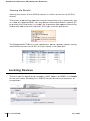
Installing RF Plan . . . . . . . . . . . . . . . . . .
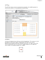
Launching RF Plan . . . . . . . . . . . . . . . . .
RF Plan Basics . . . . . . . . . . . . . . . . . . . . .
Page Summary . . . . . . . . . . . . . . . . . . .
Page Fields . . . . . . . . . . . . . . . . . . . . .
Navigation . . . . . . . . . . . . . . . . . . . . . .
Applying and Saving . . . . . . . . . . . . . . . .
Next Step Button . . . . . . . . . . . . . . . . . .
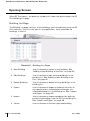
Opening Screen. . . . . . . . . . . . . . . . . . . . .
Using RF Plan . . . . . . . . . . . . . . . . . . . . . .
Task Overview . . . . . . . . . . . . . . . . . . .
Planning Requirements . . . . . . . . . . . . . .
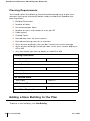
Adding a New Building to the Plan . . . . . . . . . .
Planning Pages . . . . . . . . . . . . . . . . . . .
Locating Devices . . . . . . . . . . . . . . . . . . . .
.
.
.
.
.
.
.
.
.
.
.
.
.
.
.
.
.
.
.
25
Security Options . .
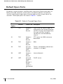
Default Open Ports . . . . .
AOS-W Security Options .
........
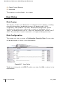
User Roles
Role Design . . . . . . .
Role Configuration . . .
.
.
.
.
.
.
.
.
.
.
.
.
.
.
.
.
.
.
.
.
.
.
.
.
.
Firewall and Traffic Policies .
.
.
.
.
.
.
.
.
.
.
.
.
.
.
.
.
.
.
.
.
.
.
.
.
.
.
.
.
.
.
.
.
.
.
.
.
.
.
.
.
.
.
.
.
.
.
.
.
.
.
.
.
.
.
.
.
.
.
.
.
.
.
.
.
.
.
.
.
.
.
.
.
.
.
.
.
.
Introduction to Firewall and Traffic Policies .
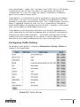
Configuring Traffic Policies . . . . . . . . . .
Access Control Lists . . . . . . . . . . . . . .
Standard ACLs . . . . . . . . . . . . . . . . .
Extended ACLs . . . . . . . . . . . . . . . . .
MAC ACLs . . . . . . . . . . . . . . . . . . .
Ethertype ACLs . . . . . . . . . . . . . . . . .
Authentication and Accounting Servers . . . . .
RADIUS . . . . . . . . . . . . . . . . . . . . .
LDAP . . . . . . . . . . . . . . . . . . . . . . .
Internal Authentication Database . . . . . . .
Accounting . . . . . . . . . . . . . . . . . . .
.
.
.
.
.
.
.
.
.
.
.
.
.
.
.
.
.
.
.
.
.
.
.
.
.
.
.
.
.
.
.
.
.
.
.
.
.
.
.
.
.
.
.
.
.
.
.
.
.
.
.
.
.
.
.
.
25
26
26
26
27
27
27
28
29
29
29
30
31
31
32
32
41
52
55
.
.
.
.
.
.
.
.
.
.
.
.
.
.
.
.
.
.
56
59
60
60
60
62
62
63
70
71
71
72
72
72
73
77
82
83
May 2005
Authentication Methods . . . . . .
802.1x Authentication . . . . .
VPN Authentication . . . . . . .
Captive Portal Authentication .
MAC Address Role Mapping . .
Stateful 802.1x . . . . . . . . .
SSID Role Mapping . . . . . . .
Encryption Type Role Mapping
Advanced Authentication . . . .
Configuring VPN Settings . . . . .
IPSec . . . . . . . . . . . . . . .
PPTP . . . . . . . . . . . . . . .
VPN Dialer Configuration . . . .
VPN Server Emulation . . . . . .
Advanced Authentication . . . .
SecureID Token Caching . . . .
Firewall Settings . . . . . . . . . . .
Advanced Security Options . . . .
Service Aliases . . . . . . . . . .
Source/Destination Aliases . . .
Bandwidth Contracts . . . . . .
NAT Pools . . . . . . . . . . . .
Time Range . . . . . . . . . . . .
Additional Information . . . . . . .
Encryption . . . . . . . . . . . .
Authentication . . . . . . . . . .
Supported VPN Clients . . . . .
Configuring L2TP and IPSec . .
.
.
.
.
.
.
.
.
.
.
.
.
.
.
.
.
.
.
.
.
.
.
.
.
.
.
.
.
.
.
.
.
.
.
.
.
.
.
.
.
.
.
.
.
.
.
.
.
.
.
.
.
.
.
.
.
.
.
.
.
.
.
.
.
.
.
.
.
.
.
.
.
.
.
.
.
.
.
.
.
.
.
.
.
.
.
.
.
.
.
.
.
.
.
.
.
.
.
.
.
.
.
.
.
.
.
.
.
.
.
.
.
.
.
.
.
.
.
.
.
.
.
.
.
.
.
.
.
.
.
.
.
.
.
.
.
.
.
.
.
.
.
.
.
.
.
.
.
.
.
.
.
.
.
.
.
.
.
.
.
.
.
.
.
.
.
.
.
.
.
.
.
.
.
.
.
.
.
.
.
.
.
.
.
.
.
.
.
.
.
.
.
.
.
.
.
.
.
.
.
.
.
.
.
.
.
.
.
.
.
.
.
.
.
.
.
.
.
.
.
.
.
.
.
.
.
.
.
.
.
.
.
.
.
.
.
.
.
.
.
.
.
.
.
.
.
.
.
.
.
.
.
.
.
.
.
.
.
.
.
.
.
.
.
.
.
.
.
.
.
.
.
.
.
.
.
.
.
.
.
.
.
.
.
.
.
.
.
.
.
.
83
84
88
89
91
92
94
95
96
97
97
100
101
104
105
106
107
109
109
110
112
112
113
113
114
116
117
118
Chapter 6
Common Tasks . . . . .
Basic Network Configuration .
VLANs . . . . . . . . . . .
Port Trunks . . . . . . . . .
Spanning Tree . . . . . . .
.
.
.
.
.
.
.
.
.
.
.
.
.
.
.
.
.
.
.
.
.
.
.
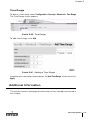
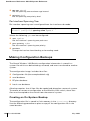
Making Configuration Backups
Creating an On-System Backup .
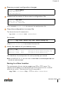
Saving to a New Location . . . .
Restoring the Configuration File .
Annotating Configuration Files . .
Upgrading the AOS-W Software . . .
Reset Configuration to Defaults . . .
.
.
.
.
.
.
.
.
.
.
.
.
.
.
.
.
.
.
.
.
.
.
.
.
.
.
.
.
.
.
.
.
.
.
.
.
.
.
.
.
.
.
.
.
.
.
.
.
.
.
.
.
.
.
.
.
.
.
.
.
.
.
.
.
.
.
.
.
.
.
.
.
.
.
.
.
.
.
.
.
.
.
.
.
.
.
.
.
.
.
.
.
.
.
.
.
. 123
. 123
. 123
. 125
. 125
. 126
. 126
. 127
. 128
. 128
. 129
. 133
Chapter 7
Air Management. . . . .
Required Components . . . . .
Wireless LAN Classification . .
AP Classifications . . . . . .
.
.
.
.
.
.
.
.
.
.
.
.
.
.
.
.
.
.
.
.
.
.
.
.
.
.
.
.
.
.
.
.
.
.
.
.
.
.
.
.
.
.
.
.
.
. 135
. 135
. 136
. 136
. 137
.
.
.
.
Wireless Client Station Classifications
v
OmniAccess Reference: AOS-W System Reference
Chapter 8
Chapter 9
Enforcement Policies . . . . . . . . . .
AP Policies . . . . . . . . . . . . .
Wireless Client Station Policies . .
Global Policies . . . . . . . . . . .
Statistics Events . . . . . . . . . . . .
General WMS Attributes. . . . . . . .
AiroPeek Support for Packet Capture
Starting Packet Capture . . . . . .
The AiroPeek Application . . . . .
Stopping Packet Capture . . . . .
Remediation with Sygate . . . . . . .
.
.
.
.
.
.
.
.
.
.
.
.
.
.
.
.
.
.
.
.
.
.
.
.
.
.
.
.
.
.
.
.
.
.
.
.
.
.
.
.
.
.
.
.
.
.
.
.
.
.
.
.
.
.
.
.
.
.
.
.
.
.
.
.
.
.
.
.
.
.
.
.
.
.
.
.
.
.
.
.
.
.
.
.
.
.
.
.
.
.
.
.
.
.
.
.
.
.
.
802.1x Client Setup . . . . . .
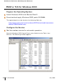
PEAP or TLS for Windows 2000 . . .
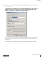
Prepare the Operating System . .
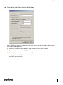
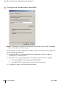
Configure the Service . . . . . . .
Validate the User Credentials . . .
PEAP or TLS for Windows XP . . . .
Cisco-PEAP for Windows XP . . . . .
Prepare the Operating System . .
.
.
.
.
.
.
.
.
.
.
.
.
.
.
.
.
Enable Wireless Zero Configuration .
Configure the Cisco ACU . . . . . . .
.
.
.
.
.
.
.
.
.
.
.
.
.
.
.
.
.
.
.
.
.
.
.
.
.
.
.
.
.
.
.
.
.
.
.
.
.
.
.
.
.
.
.
.
.
.
.
.
.
.
Configure the Wireless Network Connection .
Validate the User Credentials . . . . . . . . . .
.
.
.
.
.
.
.
.
.
.
.
.
.
.
.
.
.
.
.
.
.
.
.
137
137
141
143
143
144
146
146
147
148
148
151
152
152
152
158
160
162
162
162
164
167
172
Basic Switch Configuration . . . . . . . . 175
General Configuration . . . . . . . . . . . . . . . . . . 175
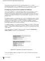
Configuring the Switch Role . . . . . . . . . . . . 175
Configuring the Switch/Loopback IP Address . . 176
Mobility Configuration . . . . . . . . . . . . . . . . 177
Wi-Fi MUX Configuration . . . . . . . . . . . . . . 177
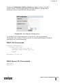
MUX CLI Commands . . . . . . . . . . . . . . . . . 179
MUX Server CLI Commands . . . . . . . . . . . . 179
Setting the 802.11d Regulatory Domain . . . . . . 180
Configuring Time Zones . . . . . . . . . . . . . . . 180
Configuring NTP Servers . . . . . . . . . . . . . . 180
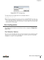
Port Configuration . . . . . . . . . . . . . . . . . . . . 181
Port Selection Options . . . . . . . . . . . . . . . . 181
Port Selection . . . . . . . . . . . . . . . . . . . . . 182
Port Configuration Options . . . . . . . . . . . . . 183
VLAN Configuration . . . . . . . . . . . . . . . . . . . 184
View Current VLAN Configuration . . . . . . . . . 185
Add New VLAN . . . . . . . . . . . . . . . . . . . . 185
Tunnels . . . . . . . . . . . . . . . . . . . . . . . . 186
IP Route Configuration. . . . . . . . . . . . . . . . 187
VRRP Configuration . . . . . . . . . . . . . . . . . . . 188
Dual Supervisor Card (Virtual Switch)
vi
Part 031652-00
May 2005
Operation . . . . . . . . . . . . . . . .
Rules of Operating a Virtual Switch . . .
Hot Swapping Support . . . . . . . . . .
Resetting the Other SC . . . . . . . . . .
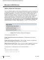
DHCP Server Configuration . . . . . . .
DHCP Pool Configuration . . . . . . . . .
DHCP Excluded Address Configuration .
Chapter 10
.
.
.
.
.
.
.
.
.
.
.
.
.
.
.
.
.
.
.
.
.
.
.
.
.
.
.
.
.
.
.
.
.
.
.
802.1x Configuration . . . . . . . . .
Introduction
..................
Background . . . . . . . . . . . . . . . . .
Definitions and Common Abbreviations .
Configuring the Switch for 802.1x . . . . . .
.
.
.
.
.
.
.
.
.
.
Creating an Authentication Server Instance .
Assigning Default Roles . . . . . . . . . . . .
Configuring the 802.1x State Machine . . . .
....................
Certificates
.
.
.
.
.
.
.
.
.
. 195
. 195
. 195
. 196
. 197
. 197
. 201
. 204
. 212
Introduction to Server, Client, and CA
Certificates . . . . . . . . . . . . . . . . . . .
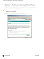
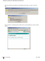
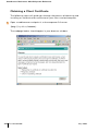
Obtaining A Certification Authority (CA)
Certificate . . . . . . . . . . . . . . . . . . .
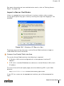
Obtaining a Server Certificate . . . . . . . . . .
Obtaining a Client Certificate . . . . . . . . . . .
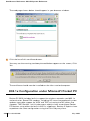
802.1x Configuration under Microsoft Pocket PC .
Configuration using Pocket PC Embedded
Supplicant . . . . . . . . . . . . . . . . . . . . .
Export Trusted Certification Authority . . . . .
Install Certificate Authority . . . . . . . . . . . .
Configure Wireless Settings . . . . . . . . . . .
Login to Wireless Network . . . . . . . . . . . .
Configuration using Funk Odyssey Client . . .
Certificate Configuration . . . . . . . . . . . . .
Odyssey Client Configuration . . . . . . . . . .
Trusted Servers Configuration . . . . . . . . . .
Profile Configuration . . . . . . . . . . . . . . .
Networks Configuration . . . . . . . . . . . . .
Connection Configuration . . . . . . . . . . . .
Push to Device . . . . . . . . . . . . . . . . . . .
Captive Portal Certificates with Intermediate
CAs . . . . . . . . . . . . . . . . . . . . . . .
Chapter 11
190
191
191
191
192
192
194
.
212
.
.
.
.
214
217
224
230
.
.
.
.
.
.
.
.
.
.
.
.
.
231
231
231
232
232
232
233
233
233
234
234
234
234
.
235
802.1x Solution Cookbook . . . . . . . . . 237
Physical Topology . . . . . . . . . . . . . . . . . . . . 238
vii
OmniAccess Reference: AOS-W System Reference
Wireless Network Operation . . . . . . . . . . .
Wireless Laptops . . . . . . . . . . . . . . . .
Printers . . . . . . . . . . . . . . . . . . . . .
OmniAccess 6000 Switch Configuration . .
Firewall Policies. . . . . . . . . . . . . . . . .
User Role Configuration . . . . . . . . . . . .
Authentication Parameters . . . . . . . . . .
VLAN and IP Address Configuration . . . . .
Wireless Configuration . . . . . . . . . . . .
AP Configuration . . . . . . . . . . . . . . . .
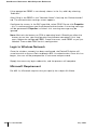
Microsoft Active Directory Server Configuration
Remote Access Permission . . . . . . . . . .
Windows Group Membership Configuration
Group Policy Configuration . . . . . . . . . .
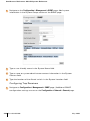
Microsoft Internet Authentication Server
Configuration . . . . . . . . . . . . . . . . . .
RADIUS Client Configuration . . . . . . . . .
Policy Configuration . . . . . . . . . . . . . .
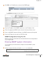
Microsoft Windows XP Client Configuration . .
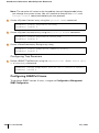
Microsoft PocketPC 2003 Client Configuration .
Export Trusted Certification Authority . . . .
Install Certificate Authority . . . . . . . . . .
Configure Wireless Settings . . . . . . . . .
Login to Wireless Network . . . . . . . . . .
Microsoft Requirement . . . . . . . . . . . .
Chapter 12
Chapter 13
viii
Part 031652-00
.
.
.
.
.
.
.
.
.
.
.
.
.
.
.
.
.
.
.
.
.
.
.
.
.
.
.
.
.
.
.
.
.
.
.
.
.
.
.
.
.
.
238
238
242
242
242
244
245
246
247
248
248
248
249
249
.
.
.
.
.
.
.
.
.
.
.
.
.
.
.
.
.
.
.
.
.
.
.
.
.
.
.
.
.
.
251
251
251
253
254
254
255
255
256
256
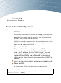
Switch Management Configuration
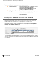
SNMP Configuration Using Web UI . . . . . .
SNMP Configuration Using The CLI . . . . . .
Configuring SNMPv3 Users . . . . . . . . . . .
. 257
. . 257
. . 259
. . 260
Configuring Administrative Access Using
Web UI . . . . . . . . . . . . . . . . . . . . .
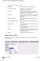
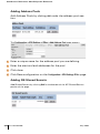
Adding and Changing Administrative Access
Using the CLI . . . . . . . . . . . . . . . . .
Adding Auth Servers . . . . . . . . . . . . . . .
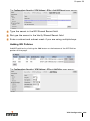
Logging
.....................
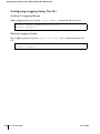
Configuring Logging Using Web UI . . . . . .
Configuring Logging Using The CLI . . . . . .
..
261
.
.
.
.
.
265
267
267
268
270
Wireless LAN Configuration . . . .
Wireless LAN Configuration . . . . . . . . . . .
Wireless LAN Network (SSID) Configuration .
Adding a New SSID . . . . . . . . . . . . .
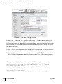
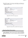
Adjusting Radio Parameters . . . . . . . . . . .
Using ARM . . . . . . . . . . . . . . . . . .
Advanced Location-Based AP Configuration .
General Wireless LAN Settings . . . . . . .
.
.
.
.
.
.
.
.
.
.
.
.
.
.
.
.
.
.
.
.
.
.
.
.
.
.
.
.
.
273
.
.
.
.
.
.
.
273
273
274
279
284
284
287
May 2005
Chapter 14
Radio Resource Management
Introduction
................
................
Calibration
Optimization
................
Self-Healing . . . . . . . . . . . . . . .
Load Balancing . . . . . . . . . . . . . .
Client and AP DoS Protection . . . . . . .
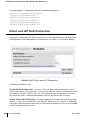
Configuration of RF Monitoring . . . . . .
Coverage Hole Detection . . . . . . . .
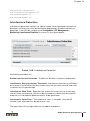
Interference Detection . . . . . . . . .
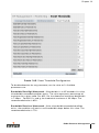
Event Threshold Configuration . . . . .
Advanced Parameters . . . . . . . . . .
.
.
.
.
.
.
.
.
.
.
.
.
.
.
.
.
.
.
.
.
.
.
.
.
.
.
.
.
.
.
.
.
.
.
.
.
.
.
.
.
.
.
.
.
.
.
.
.
.
.
.
.
.
.
.
.
.
.
.
.
Chapter 15
Intrusion Detection Configuration
Wireless LAN Intrusion Detection . . . . . . . .
...................
Rogue AP
Denial of Service . . . . . . . . . . . . . . . . . .
Rate Analysis. . . . . . . . . . . . . . . . . .
FakeAP Detection . . . . . . . . . . . . . . .
Man-in-the-Middle . . . . . . . . . . . . . . . . .
MAC Spoofing . . . . . . . . . . . . . . . . .
Station Disconnection Detection. . . . . . .
EAP Handshake Analysis . . . . . . . . . . .
Sequence Number Analysis . . . . . . . . .
AP Impersonation Protection. . . . . . . . .
Signature Detection . . . . . . . . . . . . . . . .
Wireless LAN Policies . . . . . . . . . . . . . . .
Ad-hoc Network Protection . . . . . . . . .
Wireless Bridge Detection . . . . . . . . . .
Misconfigured AP Protection . . . . . . . .
Weak WEP Detection . . . . . . . . . . . . .
.
.
.
.
.
.
.
.
.
.
.
.
.
.
.
.
.
.
.
.
.
.
.
.
.
.
.
.
.
.
.
.
.
.
.
.
Chapter 16
Authentication Server
Configuration . . . . . . . . . . . . .
Introduction
..................
Configuring RADIUS Servers with Web UI . .
Server Rules . . . . . . . . . . . . . . . . .
Configuring Attributes . . . . . . . . . . .
Configuring LDAP Servers with Web UI . . .
Adding a Server Rule . . . . . . . . . . . .
.
.
.
.
.
.
.
.
.
.
.
.
.
.
. 289
. 289
. 289
. 291
. 291
. 292
. 294
. 295
. 295
. 297
. 298
. 301
. 305
. 305
. 307
. 308
. 308
. 310
. 311
. 312
. 312
. 313
. 314
. 315
. 316
. 320
. 320
. 321
. 321
. 323
Multi-Tenancy Policies and Honeypot Defense . 324
MAC OUI Checking . . . . . . . . . . . . . . . . . 325
.
.
.
.
.
.
.
Configuring the Internal Authentication Database
with Web UI . . . . . . . . . . . . . . . . . . . .
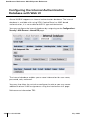
Configuring RADIUS Accounting with Web UI . . .
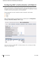
Configuring 802.1x Authentication with Web UI . .
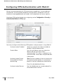
Configuring VPN Authentication with Web UI . . .
. 327
. 327
. 328
. 330
. 331
. 333
. 334
.
.
.
.
335
336
337
339
ix
OmniAccess Reference: AOS-W System Reference
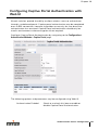
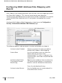
Configuring Captive Portal Authentication with
Web UI
.....................
Configuring MAC Address Role Mapping with
.....................
Web UI
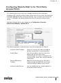
Configuring Stateful 802.1x for Third Party
Access Points . . . . . . . . . . . . . . . . . .
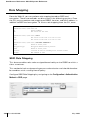
Role Mapping . . . . . . . . . . . . . . . . . . . . .
SSID Role Mapping . . . . . . . . . . . . . . . .
Encryption Type Role Mapping . . . . . . . . .
Configuring Advanced Conditions . . . . . . .
Configuring General AAA Settings Using the CLI .
Configuring RADIUS Servers Using the CLI . . . .
Server Rules. . . . . . . . . . . . . . . . . . . .
Configuring LDAP Servers Using the CLI . . . . .
Server Rules. . . . . . . . . . . . . . . . . . . .
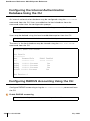
Configuring the Internal Authentication Database
Using the CLI . . . . . . . . . . . . . . . . . . .
Configuring RADIUS Accounting Using the CLI . .
Configuring 802.1x Authentication Using the CLI
Adding 802.1x Authentication Servers . . . .
Configuring VPN Authentication Using the CLI . .
Configuring Captive Portal Authentication
Using the CLI . . . . . . . . . . . . . . . . . . .
Configuring MAC Address Role Mapping
Using the CLI . . . . . . . . . . . . . . . . . . .
Configuring Stateful 802.1x Using the CLI . . . .
AP/Server Configuration for Stateful 802.1x .
Role Mapping . . . . . . . . . . . . . . . . . . . . .
SSID Role Mapping . . . . . . . . . . . . . . . .
Encryption Type Role Mapping . . . . . . . . .
Notes on Advanced AAA Features . . . . . . . . .
The Problem . . . . . . . . . . . . . . . . . . .
The AOS-W Solution . . . . . . . . . . . . . . .
Chapter 17
Chapter 18
x
Part 031652-00
IAS Server Configuration
Starting the IAS Server . . . . . . .
Creating NAS Client Entries . . . . .
Creating Remote Access Policies . .
Adding a User . . . . . . . . . . . . .
.
.
.
.
.
.
.
.
.
.
.
.
.
.
.
.
.
.
.
.
.
.
.
.
.
Firewall Configuration .
Setting Policies Using Web UI .
Aliases . . . . . . . . . . . . .
Defining Service Aliases . . .
.
.
.
.
.
.
.
.
.
.
.
.
.
.
.
.
.
.
.
.
..
340
..
343
.
.
.
.
.
.
.
.
.
.
.
.
.
.
.
.
.
.
.
.
344
345
345
346
346
348
348
349
350
352
.
.
.
.
.
.
.
.
.
.
353
353
354
357
357
..
357
.
.
.
.
.
.
.
.
.
359
359
360
360
360
360
361
361
362
.
.
.
.
.
.
.
.
.
.
.
.
.
.
.
.
.
.
.
.
.
.
.
.
.
.
.
.
.
.
.
.
.
.
.
.
.
Defining Source and Destination Aliases .
Firewall Policies. . . . . . . . . . . . . . . .
.
.
.
.
.
.
.
.
.
.
.
.
.
.
.
.
.
.
.
.
.
.
.
.
.
.
.
.
.
.
.
367
368
369
372
376
381
381
381
381
383
385
May 2005
Defining Roles Using Web UI . . . . . . . . .
Role Design . . . . . . . . . . . . . . . .
Configuring Roles . . . . . . . . . . . . .
Setting Policies Using the CLI . . . . . . . .
Defining Service Aliases . . . . . . . . .
Defining Source and Destination Aliases
Firewall Policies . . . . . . . . . . . . . .
Defining Roles Using the CLI . . . . . . . . .
Configuring Roles . . . . . . . . . . . . .
Defining Access Control Lists in the CLI . .
Standard ACLs . . . . . . . . . . . . . . .
Extended ACLs . . . . . . . . . . . . . .
MAC ACLs . . . . . . . . . . . . . . . . .
Ethertype ACLs . . . . . . . . . . . . . .
.
.
.
.
.
.
.
.
.
.
.
.
.
.
.
.
.
.
.
.
.
.
.
.
.
.
.
.
.
.
.
.
.
.
.
.
.
.
.
.
.
.
.
.
.
.
.
.
.
.
.
.
.
.
.
.
.
.
.
.
.
.
.
.
.
.
.
.
.
.
Chapter 19
Captive Portal Setup . . . . . . . .
Overview
.................
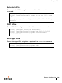
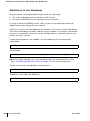
Add Users to the Database . . . . . . . .
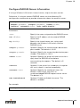
Configure RADIUS Server Information .
Apply a Server to Captive Portal . . . . .
Customize the Logon Role . . . . . . . .
Allow Guest Access . . . . . . . . . . . .
Configure Other User Roles . . . . . . .
Configuring Role Derivation . . . . . . .
Import a Server Certificate . . . . . . . .
Customize the Login Screen . . . . . . .
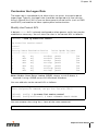
Sample Configuration . . . . . . . . . . . . .
Show Commands . . . . . . . . . . . . . . .
.
.
.
.
.
.
.
.
.
.
.
.
.
.
.
.
.
.
.
.
.
.
.
.
.
.
.
.
.
.
.
.
.
.
.
.
.
.
.
.
.
.
.
.
.
.
.
.
.
.
.
.
. 401
. 401
. 402
. 403
. 404
. 405
. 408
. 409
. 410
. 411
. 413
. 414
. 415
Chapter 20
Setting Access Rights
Introduction
..........
Defining Alias’ . . . . . . . . . .
Defining Service Alias’ . . .
Defining Destination Alias’ .
Chapter 21
.
.
.
.
.
.
.
.
.
.
Creating Session ACLs and Roles .
.
.
.
.
.
.
.
.
.
.
.
.
389
389
390
394
394
396
396
398
398
398
398
399
399
399
Creating A Session ACL for Logon
Creating Session ACLs For Users .
Role Derivation . . . . . . . . . . . . . .
How Role Derivation Works . . . .
Show Commands . . . . . . . . . . . .
.
.
.
.
.
.
.
.
.
.
.
.
.
.
.
.
.
.
.
.
.
.
.
.
.
.
.
.
.
.
.
.
.
.
.
.
.
.
.
.
.
.
.
.
.
.
.
.
.
.
.
.
.
.
.
.
.
.
.
.
.
.
.
.
.
.
.
.
.
.
.
.
.
.
.
.
.
. 419
. 419
. 420
. 420
. 420
. 421
. 421
. 421
. 422
. 422
. 424
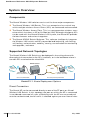
Access Point Setup. . . . . . .
System Overview . . . . . . . . . . . .
Components . . . . . . . . . . . . .
Supported Network Topologies . .
Access Point Setup . . . . . . . . . . .
Requirements . . . . . . . . . . . .
.
.
.
.
.
.
.
.
.
.
.
.
.
.
.
.
.
.
.
.
.
.
.
.
.
.
.
.
.
.
.
.
.
.
.
.
.
.
.
.
.
.
. 425
. 426
. 426
. 426
. 427
. 427
xi
OmniAccess Reference: AOS-W System Reference
Chapter 22
Chapter 23
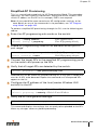
AP Provisioning. . . . . . . . . . . . . . . . . .
Plug and Play . . . . . . . . . . . . . . . . .
Simplified AP Provisioning . . . . . . . . .
AP Programming Mode . . . . . . . . . . .
Manual AP Provisioning . . . . . . . . . . .
AP Reprovisioning . . . . . . . . . . . . . .
Accessing the AP Boot Prompt . . . . . . .
Initial Configuration . . . . . . . . . . . . .
Advanced AP Configuration. . . . . . . . .
GRE Tunnel Configuration . . . . . . . . . .
Wireless LAN Switch Setup for APs . . . . . .
Configuration Profiles . . . . . . . . . . . .
AP Attribute Commands . . . . . . . . . .
Wireless Client Station Attributes . . . . .
Order of Precedence for Profile Attributes
CLI Configuration Examples . . . . . . . . .
Viewing AP Attribute Settings . . . . . . .
Viewing AP Information and Statistics . . .
AP Reprovisioning . . . . . . . . . . . . . . . .
.
.
.
.
.
.
.
.
.
.
.
.
.
.
.
.
.
.
.
.
.
.
.
.
.
.
.
.
.
.
.
.
.
.
.
.
.
.
.
.
.
.
.
.
.
.
.
.
.
.
.
.
.
.
.
.
.
.
.
.
.
.
.
.
.
.
.
.
.
.
.
.
.
.
.
.
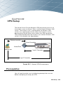
VPN Setup . . . . . . . .
Prerequisites . . . . . . . . .
Data Used In The Examples .
Network Setup . . . . . . . .
RADIUS Server Setup . . . .
Internal Database Setup . . .
.
.
.
.
.
.
.
.
.
.
.
.
.
.
.
.
.
.
.
.
.
.
.
.
.
.
.
.
.
.
.
.
.
.
.
.
.
.
.
.
.
.
.
.
.
.
.
.
.
.
.
.
.
.
.
.
.
.
.
.
.
.
.
.
.
.
.
.
.
.
.
.
.
.
.
.
.
.
.
.
.
.
.
.
.
.
.
.
.
.
.
.
.
.
.
.
.
.
.
.
.
.
.
.
.
.
.
.
.
.
.
.
.
.
.
.
.
.
.
.
.
.
.
.
.
.
.
.
.
.
.
.
.
.
.
.
.
.
.
.
L2TP IPSec VPN Server Setup
Alcatel Switch VPN Dialer Setup
.
...........
.
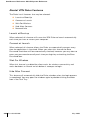
VPN Dialer
.
Before You Begin . . . . . . .
Downloading the Client . . .
.
.
Installation . . . . . . . . . .
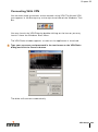
Connecting With VPN . . . .
.
Alcatel VPN Dialer Features .
.
.
Troubleshooting . . . . . . .
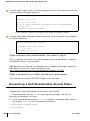
Generating a Self-Distributable Alcatel Dialer .
.
.
.
.
.
.
.
.
.
.
.
.
.
.
.
.
.
.
.
.
.
.
.
.
.
.
.
.
.
.
.
.
.
.
.
.
.
.
.
.
.
.
.
.
.
.
.
.
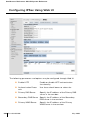
VPN Configuration . . . . .
Configuring IPSec Using Web UI .
Adding Address Pools . . . . .
Adding IKE Shared Secrets . .
Adding IKE Policies . . . . . . .
............
L2TP
.
.
.
.
.
.
.
.
.
.
.
.
.
.
.
.
.
.
.
.
.
.
.
.
.
.
.
.
.
.
.
.
.
.
.
.
.
.
.
.
.
.
.
.
.
.
.
.
.
.
.
.
.
.
.
.
.
.
.
.
.
.
.
.
.
.
.
.
.
.
.
.
.
.
.
483
.
.
.
.
.
Configuring PPTP Using Web UI
.
Configuring The VPN Dialer Using Web UI
.
.
Configuring VPN Server Emulation Using Web UI
Configuring SecureID Token Caching Using Web UI .
xii
Part 031652-00
428
428
429
430
436
436
437
441
444
453
454
454
459
462
463
465
468
471
478
483
484
484
485
486
487
488
490
490
490
494
497
498
500
502
505
506
508
508
509
510
510
511
514
515
May 2005
Configuring IPSec Using the CLI . . . . . . . . . .
Configuring PPTP Using the CLI . . . . . . . . . .
Configuring the VPN Dialer Using the CLI. . . . .
Configuring VPN Server Emulation Using the CLI
Configuring SecureID Token Caching Using
....................
Web UI
VPN Quick Start Guide . . . . . . . . . . . . . . .
Requirements From Customer . . . . . . . . .
Network Topology In Examples . . . . . . . .
Setting Up a VPN . . . . . . . . . . . . . . . .
Verification and Troubleshooting . . . . . . .
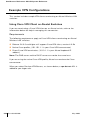
Example VPN Configurations . . . . . . . . . . . .
Using Cisco VPN Client on Alcatel Switches .
Typical Third-Party VPN Clients . . . . . . . .
.
.
.
.
.
.
.
.
.
.
.
.
Reboot Peer Supervisor Card .
Clear Config . . . . . . . . . . .
Synchronize . . . . . . . . . . .
Boot Parameters . . . . . . . . .
File Maintenance . . . . . . . . . . .
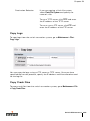
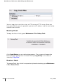
Copy Files . . . . . . . . . . . .
Copy Logs . . . . . . . . . . . .
Copy Crash Files . . . . . . . . .
Backup Flash . . . . . . . . . . .
Restore Flash. . . . . . . . . . .
Delete Files . . . . . . . . . . . .
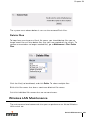
Wireless LAN Maintenance . . . . .
Rebooting Access Points . . . .
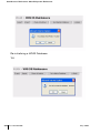
Managing the WMS Database .
Captive Portal Maintenance . . . .
Customizing the Login Page . .
Upload Certificate . . . . . . . .
Upload Custom Login Pages . .
.
.
.
.
.
.
.
.
.
.
.
.
.
.
.
.
.
.
.
.
.
.
.
.
.
.
.
.
.
.
.
.
.
.
.
.
.
.
.
.
.
.
.
.
.
.
.
.
.
.
.
.
.
.
.
.
.
.
.
.
.
.
.
.
.
.
.
.
.
.
.
.
.
.
.
.
.
.
.
.
.
.
.
.
.
.
.
.
.
.
.
.
.
.
.
.
.
520
521
521
521
521
525
530
530
537
.
.
.
.
.
.
.
.
.
.
.
.
.
.
.
.
.
.
.
.
.
.
. 543
. 543
. 543
. 544
. 545
. 545
. 546
. 546
. 547
. 547
. 549
. 549
. 550
. 550
. 551
. 551
. 552
. 552
. 554
. 555
. 555
. 556
Monitoring and Troubleshooting .
Chapter 25
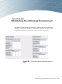
Monitoring the Wireless
Environment . . . . . . . . . . .
Network Monitoring . . . . . . . . . . . .
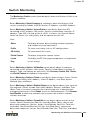
Switch Monitoring . . . . . . . . . . . . .
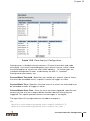
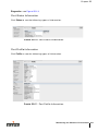
Sample Monitoring Information . . .
Events
...............
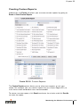
Creating Custom Reports . . . . . . .
.
.
.
.
.
.
.
.
.
.
.
.
.
.
.
.
.
.
.
.
.
.
.
.
.
.
.
.
.
.
.
.
.
.
.
.
.
Part 3
.
.
.
.
.
.
.
.
.
.
.
.
.
.
.
.
.
.
.
.
.
.
.
.
.
.
.
.
516
517
518
519
Switch Maintenance.
Switch Level Maintenance . .
Image Management . . . .
Reboot Switch . . . . . . .
.
.
.
.
.
.
.
.
.
.
.
.
.
.
.
.
.
.
.
.
.
.
.
.
.
.
.
.
.
.
.
.
Chapter 24
.
.
.
.
.
.
.
.
.
.
.
.
.
.
.
.
.
.
.
.
.
.
.
.
.
.
.
.
.
.
.
.
.
.
.
.
.
.
.
.
.
.
.
.
559
. 561
. 562
. 563
. 564
. 573
. 575
xiii
OmniAccess Reference: AOS-W System Reference
Wireless LAN Monitoring . . . .
Debug Information . . . . . . . .
Creating Custom Logs . . . . . .
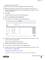
Reports
...........
Example Report: Rogue APs
AP Reports . . . . . . . . . .
Custom Reports . . . . . . .
.
.
.
.
.
.
.
.
.
.
.
.
.
.
.
.
.
.
.
.
.
.
.
.
.
.
.
.
.
.
.
.
.
.
.
.
.
.
.
.
.
.
.
.
.
.
.
.
.
.
.
.
.
.
.
.
.
.
.
.
.
.
.
.
.
.
.
.
.
.
.
.
.
.
.
.
.
576
576
577
577
578
579
580
Chapter 26
Firewall Logging . . . . . . . . . . . . . . . . . 583
Log Entries (alphabetical) . . . . . . . . . . . . . . . . 583
Chapter 27
Troubleshooting AOS-W
Environments. . . . . . .
Basic Connectivity . . . . . . . . .
General . . . . . . . . . . . . .
Client cannot find AP . . . . .
.
.
.
.
.
.
.
.
.
.
.
.
.
.
.
.
.
.
.
.
.
.
.
.
.
.
.
.
.
.
.
.
.
.
.
.
Client finds AP, but cannot associate
Client associates to AP, but higher-layer
authentication fails . . . . . . . . . . . . .
Client associates/authenticates, but has
no network connectivity . . . . . . . . . .
Client initially has network connectivity,
then loses connectivity . . . . . . . . . .
Client has network connectivity, then loses
wireless association . . . . . . . . . . . .
Client experiences poor performance . . . .
Troubleshooting Access/Grid Points . . . . . . .
Authentication . . . . . . . . . . . . . . . . . . .
802.1x . . . . . . . . . . . . . . . . . . . . . .
VPN . . . . . . . . . . . . . . . . . . . . . . .
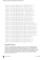
Sample Packet Captures. . . . . . . . . . . . . .
Broadcast Probe Request Frame . . . . . . .
FCS - Frame Check Sequence . . . . . . . .
Specific Network Probe Request Frame . . .
Beacon Frame . . . . . . . . . . . . . . . . . .
Probe Response Frame . . . . . . . . . . . .
802.11 Authenticate Frame . . . . . . . . . .
802.11 Authenticate Response (Success) . .
Association Request Frame (includes WPA)
Association Response . . . . . . . . . . . . .
Packet Sniffing . . . . . . . . . . . . . . . . . . .
Packet Capture . . . . . . . . . . . . . . . . .
SESSION MIRRORING . . . . . . . . . . . . .
Chapter 28
xiv
.
.
.
.
.
.
.
Part 031652-00
.
.
.
.
.
.
.
.
.
.
587
.
.
.
.
587
589
589
592
...
595
...
595
...
596
.
.
.
.
.
.
.
.
.
.
.
.
.
.
.
.
.
.
.
597
598
599
603
603
606
610
610
611
611
613
615
617
618
619
622
623
624
625
.
.
.
.
.
.
.
.
.
.
.
.
.
.
.
.
.
.
.
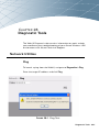
Diagnostic Tools. . . . . . . . . . . . . . . . .
.
.
.
.
.
.
.
.
.
.
.
.
.
.
.
.
.
.
.
627
May 2005
Network Utilities . . . . . . . . . .
Ping . . . . . . . . . . . . . . .
Traceroute . . . . . . . . . . .
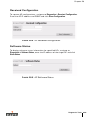
General Information . . . . . . . .
Contacting Technical Support
Access Point Diagnostics. . . . .
Received Configuration . . . .
Software Status . . . . . . . .
Debug Log . . . . . . . . . . .
Detailed Statistics . . . . . . .
Web Diagnostic . . . . . . . .
.
.
.
.
.
.
.
.
.
.
.
.
.
.
.
.
.
.
.
.
.
.
.
.
.
.
.
.
.
.
.
.
.
.
.
.
.
.
.
.
.
.
.
.
.
.
.
.
.
.
.
.
.
.
.
.
.
.
.
.
.
.
.
.
.
.
.
.
.
.
.
.
.
.
.
.
.
.
.
.
.
.
.
.
.
.
.
.
.
.
.
.
.
.
.
.
.
.
.
627
627
628
628
628
628
629
629
630
630
631
Part 4
Command Reference . . . . . . . . . . .
633
Chapter 29
AOS-W Commands . . . . . . . . . . .
Understanding the Command Line Interface .
Navigating the CLI . . . . . . . . . . . . . .
Tips . . . . . . . . . . . . . . . . . . . . . .
Execute Mode Commands . . . . . . . . . . .
Privileged Mode Commands . . . . . . . . . .
aaa Commands . . . . . . . . . . . . . . .
clear Commands . . . . . . . . . . . . . . . . .
Configure Terminal Commands . . . . . . . .
.
.
.
.
.
.
.
.
.
.
.
.
.
.
.
.
.
.
.
.
.
.
.
.
.
.
.
.
.
.
.
.
.
.
.
.
.
.
.
.
.
.
.
.
.
.
.
.
.
. 635
. 635
. 635
. 636
. 637
. 639
. 641
. 645
. 672
xv
OmniAccess Reference: AOS-W System Reference
aaa Commands . . . . . . . . .
aaa xml-api client . . . . . .
adp Commands . . . . . . .
ads Commands . . . . . .
ap Commands . . . . . . .
arm Commands. . . . . . .
arp . . . . . . . . . . . . . .
banner motd . . . . . . . .
clock Commands . . . . . .
crypto Commands . . . . .
database synchronize . . .
destination . . . . . . . . .
dot1x Commands . . . . .
enable . . . . . . . . . . . .
encrypt . . . . . . . . . . .
firewall Commands . . . .
foreign-agent . . . . . . . .
home-agent . . . . . . . . .
hostname . . . . . . . . . .
Interface Commands . . . .
IP Commands . . . . . . . .
key . . . . . . . . . . . . . .
location . . . . . . . . . . .
logging Commands . . . .
loginsession timeout . . . .
mac-address-table static .
master-redundancy . . . .
masterip . . . . . . . . . . .
mgmt-role . . . . . . . . . .
mgmt-user . . . . . . . . .
mobagent . . . . . . . . . .
mobility . . . . . . . . . . .
mobility-local . . . . . . . .
mobmaster primary-subnet
mux-address . . . . . . . .
mux-vlan . . . . . . . . . .
netdestination . . . . . . .
newbury . . . . . . . . . . .
no . . . . . . . . . . . . . .
ntp server . . . . . . . . . .
packet-capture-defaults . .
ping . . . . . . . . . . . . .
pptp . . . . . . . . . . . . .
program-ap . . . . . . . . .
prompt . . . . . . . . . . . .
rap-wml . . . . . . . . . . .
router . . . . . . . . . . . .
sapm . . . . . . . . . . . . .
service . . . . . . . . . . . .
xvi
Part 031652-00
.
.
.
.
.
.
.
.
.
.
.
.
.
.
.
.
.
.
.
.
.
.
.
.
.
.
.
.
.
.
.
.
.
.
.
.
.
.
.
.
.
.
.
.
.
.
.
.
.
.
.
.
.
.
.
.
.
.
.
.
.
.
.
.
.
.
.
.
.
.
.
.
.
.
.
.
.
.
.
.
.
.
.
.
.
.
.
.
.
.
.
.
.
.
.
.
.
.
.
.
.
.
.
.
.
.
.
.
.
.
.
.
.
.
.
.
.
.
.
.
.
.
.
.
.
.
.
.
.
.
.
.
.
.
.
.
.
.
.
.
.
.
.
.
.
.
.
.
.
.
.
.
.
.
.
.
.
.
.
.
.
.
.
.
.
.
.
.
.
.
.
.
.
.
.
.
.
.
.
.
.
.
.
.
.
.
.
.
.
.
.
.
.
.
.
.
.
.
.
.
.
.
.
.
.
.
.
.
.
.
.
.
.
.
.
.
.
.
.
.
.
.
.
.
.
.
.
.
.
.
.
.
.
.
.
.
.
.
.
.
.
.
.
.
.
.
.
.
.
.
.
.
.
.
.
.
.
.
.
.
.
.
.
.
.
.
.
.
.
.
.
.
.
.
.
.
.
.
.
.
.
.
.
.
.
.
.
.
.
.
.
.
.
.
.
.
.
.
.
.
.
.
.
.
.
.
.
.
.
.
.
.
.
.
.
.
.
.
.
.
.
.
.
.
.
.
.
.
.
.
.
.
.
.
.
.
.
.
.
.
.
.
.
.
.
.
.
.
.
.
.
.
.
.
.
.
.
.
.
.
.
.
.
.
.
.
.
.
.
.
.
.
.
.
.
.
.
.
.
.
.
.
.
.
.
.
.
.
.
.
.
.
.
.
.
.
.
.
.
.
.
.
.
.
.
.
.
.
.
.
.
.
.
.
.
.
.
.
.
.
.
.
.
.
.
.
.
.
.
.
.
.
.
.
.
.
.
.
.
.
.
.
.
.
.
.
.
.
.
.
.
.
.
.
.
.
.
.
.
.
.
.
.
.
.
.
.
.
.
.
.
.
.
.
.
.
.
.
.
.
.
.
.
.
.
.
.
.
.
.
.
.
.
.
.
.
.
.
.
.
.
.
.
.
.
.
.
.
.
.
.
.
.
.
.
.
.
.
.
.
.
.
.
.
.
.
.
.
.
.
.
.
.
.
.
.
.
.
.
.
.
.
.
.
.
.
.
.
.
.
.
.
.
.
.
.
.
.
.
.
.
.
.
.
.
.
.
.
.
.
.
.
.
.
.
.
.
.
.
.
.
.
.
.
.
.
.
.
.
.
.
.
.
.
.
.
.
.
.
.
.
.
.
.
.
.
.
.
.
.
.
.
.
.
.
.
.
.
.
.
.
.
.
.
.
.
.
.
.
.
.
.
.
.
.
.
.
675
696
696
697
698
699
701
701
702
703
712
713
713
720
721
721
725
726
727
728
737
743
744
744
745
745
746
747
748
749
750
750
753
754
755
755
756
757
757
764
765
767
767
768
768
769
771
772
773
May 2005
shutdown . .
site-survey . .
snmp-server .
spanning-tree
stm . . . . . .
syscontact . .
syslocation . .
telnet cli. . . .
time-range . .
traceroute . .
trusted . . . .
udp-port . . .
user . . . . . .
user-role . . .
version . . . .
vlan . . . . . .
vpdn . . . . . .
vpn-dialer . . .
vrrp . . . . . .
web-server . .
web-ui . . . .
wms . . . . . .
.
.
.
.
.
.
.
.
.
.
.
.
.
.
.
.
.
.
.
.
.
.
.
.
.
.
.
.
.
.
.
.
.
.
.
.
.
.
.
.
.
.
.
.
.
.
.
.
.
.
.
.
.
.
.
.
.
.
.
.
.
.
.
.
.
.
.
.
.
.
.
.
.
.
.
.
.
.
.
.
.
.
.
.
.
.
.
.
.
.
.
.
.
.
.
.
.
.
.
.
.
.
.
.
.
.
.
.
.
.
.
.
.
.
.
.
.
.
.
.
.
.
.
.
.
.
.
.
.
.
.
.
.
.
.
.
.
.
.
.
.
.
.
.
.
.
.
.
.
.
.
.
.
.
.
.
.
.
.
.
.
.
.
.
.
.
.
.
.
.
.
.
.
.
.
.
.
.
.
.
.
.
.
.
.
.
.
.
.
.
.
.
.
.
.
.
.
.
.
.
.
.
.
.
.
.
.
.
.
.
.
.
.
.
.
.
.
.
.
.
.
.
.
.
.
.
.
.
.
.
.
.
.
.
.
.
.
.
.
.
.
.
.
.
.
.
.
.
.
.
.
.
.
.
.
.
.
.
.
.
.
.
.
.
.
.
.
.
.
.
.
.
.
.
.
.
.
.
.
.
.
.
.
.
.
.
.
.
.
.
.
.
.
.
.
.
.
.
.
.
.
.
.
.
.
.
.
.
.
.
.
.
.
.
.
.
.
.
.
.
.
.
.
.
.
.
.
.
.
.
.
.
.
.
.
.
.
.
.
.
.
.
.
.
.
.
.
.
.
.
.
.
.
.
.
.
.
.
.
.
.
.
.
.
.
.
.
.
.
.
.
.
.
.
.
.
.
.
.
.
.
.
.
.
.
.
.
.
.
.
.
.
.
.
.
.
.
.
.
.
.
.
.
.
.
.
.
.
.
.
.
.
.
.
.
.
.
.
.
.
.
.
.
.
.
.
.
.
.
.
.
.
.
.
.
.
.
.
.
.
Chapter 30
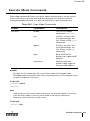
Action Commands . . . . . . . .
User Mode Commands . . . . . . . . . .
Switch Management Commands . .
Layer 2/Layer 3 Commands . . . . .
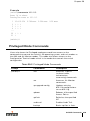
Privileged Mode Commands . . . . . . .
Switch Management Commands . .
Layer 2/Layer 3 Commands . . . . .
Air Management Commands . . . . .
Authentication Commands . . . . . .
Clear Commands . . . . . . . . . . .
Debug Commands. . . . . . . . . . .
Panic Commands . . . . . . . . . . .
Screen Display Commands . . . . . .
.
.
.
.
.
.
.
.
.
.
.
.
.
.
.
.
.
.
.
.
.
.
.
.
.
.
.
.
.
.
.
.
.
.
.
.
.
.
.
.
.
.
.
.
.
.
.
.
.
.
.
.
.
.
.
.
.
.
.
.
.
.
.
.
.
.
.
.
.
.
.
.
.
.
.
.
.
.
. 819
. 819
. 820
. 820
. 821
. 821
. 824
. 825
. 828
. 830
. 831
. 832
. 832
Chapter 31
Show Commands . . . . . . . . . . . . . . . . 833
General Switch Management
Commands . . . . . . . . . . . . . . .
Switch Management Commands . .
Configuration Manager Commands .
Layer 2/Layer 3 Commands . . . . . . .
Layer 2 Commands . . . . . . . . . .
Layer 3 Commands . . . . . . . . . .
DHCP Commands . . . . . . . . . . .
Interface Commands . . . . . . . . .
.
.
.
.
.
.
.
.
.
.
.
.
.
.
.
.
.
.
.
.
.
.
.
.
.
.
.
.
.
.
.
.
.
.
.
.
.
.
.
.
.
.
.
.
.
.
.
.
.
.
.
.
.
.
.
.
774
774
777
778
780
788
788
789
790
791
792
792
792
794
796
798
798
801
803
805
807
807
833
833
839
840
840
843
845
846
xvii
OmniAccess Reference: AOS-W System Reference
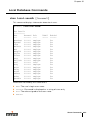
Local Database Commands . . . . . . . . . . .
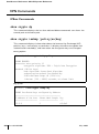
VPN Commands . . . . . . . . . . . . . . . . .
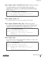
IPSec Commands . . . . . . . . . . . . . .
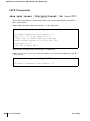
L2TP Commands . . . . . . . . . . . . . . .
VPN Dialer Commands . . . . . . . . . . . .
PPTP Commands. . . . . . . . . . . . . . .
Mobility Commands . . . . . . . . . . . . . . .
Air Management Commands . . . . . . . . . .
Air Monitor Commands . . . . . . . . . . .
WMS Commands . . . . . . . . . . . . . .
Site Survey Commands . . . . . . . . . . .
Station Management Commands . . . . .
Access Point Management Commands . . . .
Alcatel Soft AP Commands . . . . . . . . .
Authentication Commands . . . . . . . . . . .
General Authentication Commands . . . .
IEEE 802.1x Commands . . . . . . . . . . .
Accounting, Authentication, Authorization
Local Database Commands . . . . . . . . .
Dialer Commands . . . . . . . . . . . . . .
Access Lists Commands . . . . . . . . . . . .
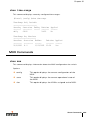
MUX Commands . . . . . . . . . . . . . . . . .
Enhanced Show Commands . . . . . . . . . .
Part 5
.
.
.
.
.
.
.
.
.
.
.
.
.
.
.
.
.
.
.
.
.
.
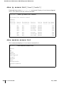
.
853
854
854
856
859
860
861
872
872
881
884
885
887
887
891
891
894
896
902
902
903
905
906
Appendices . . . . . . . . . . . . . . . . . . . .
909
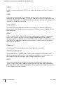
Glossary
xviii
Part 031652-00
.
.
.
.
.
.
.
.
.
.
.
.
.
.
.
.
.
.
.
.
.
.
.
.
.
.
.
.
.
.
.
.
.
.
.
.
.
.
.
.
.
.
.
.
.
.
.
.
.
.
.
.
.
.
.
.
.
.
.
.
.
.
.
.
.
.
.
.
.
911
May 2005
Preface
This preface includes the following information:
z An overview of the sections in this manual
z A list of related documentation for further reading
z A key to the various text conventions used throughout this
manual
z Alcatel support and service information
An Overview of this Manual
This manual is for network administrators and operators
responsible for configuring and monitoring the Alcatel Wireless
LAN Switch. The manual is organized as follows:
z Part 1, “Overview”
Explains the Alcatel Wireless LAN Switch interfaces, including the
Command-Line Interface (CLI) and the Web UI.
z Part 2, “Design”
Explains the basic network design issues in adding a Wireless
LAN switch to a network.
z Part 3, “Configuration”
Explains the features that can be configured for Alcatel Wireless
LAN switches.
z Part 4, “Monitoring”
Explains how Alcatel Wireless LAN switches are managed and
maintained.
z Part 5, “Common CLI Commands”
Explains the CLI syntax for commands commonly used.
z Part 6, “Appendix”
Includes a glossary of terms used in this document.
Preface
xix
OmniAccess Reference: AOS-W System Reference
Related Documents
The following items are part of the complete documentation for the Alcatel
system:
z Alcatel Wireless LAN Switch Installation Guides (OmniAccess 4308, OmniAccess Wireless LAN, and OmniAccess 6000)
z Alcatel AOS-W User Guide
z Alcatel AP Installation Guides (AP60/61 and AP70)
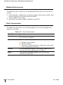
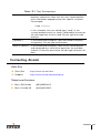
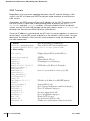
Text Conventions
The following conventions are used throughout this manual to emphasize
important concepts:
TABLE P-1 Text Conventions
Type Style
Description
Italics
This style is used to emphasize important terms and to
mark the titles of books.
System items
This fixed-width font depicts the following:
z Sample screen output
z System prompts
z Filenames, software devices, and certain commands
when mentioned in the text.
xx
Commands
In the command examples, this bold font depicts text
that the user must type exactly as shown.
Button
The name of the object (button, link, etc.) on the
interface that you click.
Part 031652-00
May 2005
TABLE P-1 Text Conventions
<Arguments>
In the command examples, italicized text within angle
brackets represents items that the user should replace
with information appropriate to their specific situation.
For example:
# send <text message>
In this example, the user would type “send” at the
system prompt exactly as shown, followed by the text of
the message they wish to send. Do not type the angle
brackets.
[ Optional ]
In the command examples, items enclosed in brackets
are optional. Do not type the brackets.
{ Item A | Item B }
In the command examples, items within curled braces
and separated by a vertical bar represent the available
choices. Enter only one choice. Do not type the braces or
bars.
Contacting Alcatel
Web Site
z Main Site
http://www.alcatel.com
z Support
http://www.alcatel.com/enterprise
Telephone Numbers
z Main US/Canada
(800) 995-2612
z Main Outside US
(818) 880-3500
Preface
xxi
OmniAccess Reference: AOS-W System Reference
xxii
Part 031652-00
May 2005
1
Part
Overview
1
OmniAccess Reference: AOS-W System Reference
2
Part 031652-00
May 2005
CHAPTER 1
Overview
The AOS-W 2.2 Interface Reference is organized by product
feature for the Alcatel Wireless LAN switches and access points.
This guide also includes best practice recommendations and
configuration examples for a number of features.
Key Features
Prevention of Layer-2 Bridging between
Wireless Users
In AOS-W, a global firewall feature has been added to deny all L2
bridging between users. Because wireless users enter the switch
through GRE tunnels, the feature has been labeled “Deny L2
Bridging between Untrusted GRE Tunnels”, and can be
configured under the global firewall settings.
Wired Port 802.1x Authentication
In AOS-W, 802.1x authentication has been extended to wired
ports as well. This implementation is different than that found on
standard Ethernet switches, as they are designed to authenticate
an entire port. Alcatel’s 802.1x implementation is designed to
authenticate individual MAC addresses, regardless of how many
MAC addresses are seen on a given port. Port-based 802.1x
authentication is automatically enabled on any port configured as
“untrusted”, as long as global 802.1x authentication has been
configured.
Overview
3
OmniAccess Reference: AOS-W System Reference
Enhanced Location Services
AOS-W 2.2 adds more precise position tracking of wireless devices by utilizing
RF triangulation. In previous AOS-W releases, the “RF Locate” feature would
display the nearest APs receiving signals from a wireless user or AP, along
with the corresponding signal strength. AOS-W 2.2 adds the ability to
triangulate position based on RF signal strength. This algorithm is accurate to
within approximately 10 meters. Note that for triangulation to function
properly, at least three sources of data are required. If three sources of data
are not available, the system will revert to showing the nearest APs receiving
signal from the device to be located. An additional restriction on triangulation
in release 2.2 is that APs must be present in the network in order to provide
live calibration data – triangulation will not function in a network with only air
monitors in this release.
Web Management Interface Enhancements
Many sections of the Web-based management interface have been changed to
improve usability. In addition, all critical features configurable from the CLI are
also now available in the Web interface.
Enhanced Network Monitoring Interface
The “Monitoring” section of the Web-based management interface has been
enhanced through the separation of network monitoring and switch
monitoring. In a network with multiple Alcatel switches, the network
monitoring section now provides an easy interface into the network view of
the system. When connected to the master switch, all users in the entire
network can now be located from the network monitoring section.
SNMPv3
Previous releases of AOS-W supported only SNMPv1 and SNMPv2c. When
connecting Alcatel components to a network management platform across an
insecure network, use of these protocols could lead to unintentional releases
of sensitive information. SNMPv3 provides the ability to encrypt SNMP
communication.
Remote Thin AP
Some customers reported problems when using Alcatel APs connected to a
switch across a low-speed link such as a frame relay connection. The issue
with this was that latency in the low-speed link would cause greater than 5ms
of delay when responding to 802.11 probe request frames from wireless
clients. Certain clients would only wait on a single channel for 5ms, and would
be on a new channel by the time the probe response arrived. AOS-W 2.2
4
Part 031652-00
May 2005
Chapter 1
provides the ability to enable local probe responses for remotely connected
APs. This feature may be configured under the Wireless LANÆAdvanced
section of the Web-based management interface, or may be configured under
the “ap location” section of the CLI.
Auto-Blacklist Firewall Extended Action
AOS-W 2.2 provides the ability to automatically blacklist (prevent association
to any AP) clients who violate a rule in a firewall policy. This is useful for
protecting wireless LANs made up of devices that cannot perform
authentication, such as Wi-Fi voice handsets or barcode scanners. Devices
such as these should be placed into a role with an extremely restrictive
firewall policy, for example allowing only SIP traffic to a SIP gateway. If an
attacker were to compromise an encryption key or spoof a MAC address on
such a network, a single firewall policy violation (i.e. sending an HTTP request
or initiating a port scan) would cause the station to be immediately
disconnected from the network. This feature may be configured by selecting
it as an extended action in any firewall policy.
Enhanced AP-Switch Discovery and Alcatel Discovery
Protocol
In order for thin APs to operate, they must be able to locate and connect to a
Wi-Fi switch. Alcatel APs have always had the ability to automatically locate a
switch, boot from it, and become operational without requiring any
configuration. In the past, this was based on APs obtaining an address
through DHCP and performing a DNS lookup on the hostname
“Alcatel-master”. While this method of switch location is still popular, a
number of customers requested alternate methods of AP configuration.
AOS-W 2.2 adds “Alcatel Discovery Protocol” (ADP) to provide this
functionality. ADP is present in the switch by loading AOS-W.
APs will go through the following sequence to locate a switch:
Power is applied. If AP does not already contain a pre-configured IP address,
it will issue a DHCP request to obtain an address.
If DHCP response contains an Alcatel vendor-specific option (see below), it
will use this vendor-specific option to contact an Alcatel switch and continue
the boot process.
If the DHCP response contains a DNS server address, the AP will perform DNS
lookup of the hostname “Alcatel-master.<subdomain>”, where <subdomain>
was learned from the DHCP server. If this request is successful, the AP will
use the returned IP address to contact an Alcatel switch and continue the
boot process.
Overview
5
OmniAccess Reference: AOS-W System Reference
If no DNS information is available, the AP will begin using Alcatel Discovery
Protocol (ADP) to locate a switch. It will alternately send out ADP broadcast
packets and ADP multicast packets until a response is received. The multicast
packet is an IP packet directed to multicast address 224.0.82.11. If a switch is
attached to the local L2 segment, it will reply to the ADP broadcast. If a switch
has joined the ADP multicast group, the intervening network will forward the
AP multicast packets to the switch and it will reply.
DHCP Configuration
DHCP servers may be configured to return Alcatel vendor-specific options to
APs. The vendor class identifier is “AlcatelAP”, and the vendor-specific option
code is 43. A sample configuration for the open-source ISC DHCP server
follows. In this example, the Alcatel switch is located at IP address 10.1.1.10.
option serverip code 43 = ip-address;
class "vendor-class" {
match option vendor-class-identifier;
}
.
.
.
subnet 10.200.10.0 netmask 255.255.255.0 {
default-lease-time 200;
max-lease-time 200;
option subnet-mask 255.255.255.0;
option routers 10.200.10.1;
option domain-name-servers 10.4.0.12;
option domain-name "test.com";
subclass "vendor-class" "AlcatelAP" {
option vendor-class-identifier "AlcatelAP";
6
Part 031652-00
May 2005
Chapter 1
option serverip 10.1.1.10;
}
range 10.200.10.200 10.200.10.252;
}
To configure Microsoft’s DHCP server for this feature:
1. Add an “option 43” entry to the desired DHCP scope that contains the IP
address of the Alcatel switch in text. An example of this is shown in the
following figure.
Overview
7
OmniAccess Reference: AOS-W System Reference
2. From a command prompt, enter:
c:\>netsh
netsh>dhcp
netsh dhcp>server \\<server_machine_name>
netsh dhcp>add optiondef 60 AlcatelAP String 0 comment=AlcatelSupport netsh
dhcp>set optionvalue 60 STRING AlcatelAP
netsh dhcp>exit
Multicast Configuration
A network supporting IP multicast must be in place to make use of the ADP
multicast capability. To configure the Alcatel switch for multicast, enter:
(config) # adp discovery enable
(config) # adp igmp-join enable
This configuration will cause the Alcatel switch to send an IGMPv2 join
message for multicast group 224.0.82.11.
8
Part 031652-00
May 2005
CHAPTER 2
Management Options
AOS-W provides a number of methods for managing your Alcatel
Wireless LAN Switch.
Command-Line Interface
The Command-Line Interface (CLI) provides the most direct
method for configuring the switch and collecting system
information. The CLI has the following features:
z Accessible from a local console terminal
z Optionally available through Telnet or SSH to local management console or remote network connection
z Comprehensive, industry-standard command system
See “Command Line Basics” on page 13 for more information.
Web Interface
The Web interface provides an intuitive, graphical interface to
special configuration and design tools. The Web interface
provides the following:
z Compatible with a standard Web browser1
z Accessible from the local management console or remote network connection
1.AOS-W requires Internet Explorer 6.0 or higher. Other browsers may work but
with limited functionality and are therefore not officially supported.
Management Options
9
OmniAccess Reference: AOS-W System Reference
z Configure and manage wireless intrusion prevention and performance policies
z Monitor the state and performance of the Wireless LAN
z Perform a site survey to assist deployment of Alcatel Access Points and Air
Monitors
z Monitor air interface security and performance events
z AP triangulation
General Screen Elements
When Web UI is started after a successful login, the browser window will
show the default page: the Monitor Summary. For ease of navigation, all of the
Web UI pages have a similar page structure:
Selected
Tool
Logout
Button
Tool Bar
Page
Display
Selected
Page
Page
Tree
FIGURE 2-1 Web UI Page Elements
z Tool Bar–This contains buttons for the various tools available in the Web UI
software. Click on a button to select the tool.
z Selected Tool–This displays the name of the currently selected tool.
10
Part 031652-00
May 2005
Chapter 2
z Page Tree–Each tool has its own information or configuration pages and
sub-pages.
The page tree lists all of the pages available when using the currently selected
tool. You can navigate to any of the listed pages by clicking on the page name.
NOTE—Some of the items in the page tree are merely headings for their sub-pages and cannot be selected. Selectable pages
become highlighted when the mouse cursor is placed over them. Non-selectable items do not react.
z Selected Page–The name of the currently selected page is highlighted in
the page tree.
z Page Display–This area displays all the information and/or input fields relevant to the current page of the current tool.
z Logout Button–Click on this button to end your Web UI session.
Page Elements
Each tool in the Web UI has its own unique information or configuration
pages, each with specialized data and control fields. Some of the page items
appear on multiple pages in multiple tools and provide a similar navigation or
configuration function in each.
Navigation Items
z Scroll-bars–In some cases, there will be more fields than can be conveniently displayed on one window. When this occurs, standard Windows
scroll-bars will be available to let you access the rest of the page.
z Page Tabs–Some pages feature a row of tabs near the top of the page display area. Each tab represents a different form available from the current
page.
z Links–Items which are underlined are linked to other pages. By clicking on
the item, the relevant item’s configuration or information page will be displayed.
Fields
z Information Fields–These fields are used only for displaying information.
The data in these fields cannot be edited directly on the displayed screen.
z Data Entry Fields–Boxed text fields contain user-configurable data. To enter
or edit the information, click inside the field box.
z Pull-down Menus–These fields allow you to select an item from a preset
list. The currently selected item is displayed in the box. When the arrow
button is selected, a list of available options appears. You can change the
current selection by clicking on any item in the options list.
z Scrolling Menus–These fields allow you to select an item from a preset list.
Use the scroll arrows to view the available options. To select a specific
item from the list, click on the item when displayed.
Management Options
11
OmniAccess Reference: AOS-W System Reference
z Check Boxes–Represented as small squares in front of the item text. These
fields allow you to turn items on or off by clicking on the check box. A feature or option will be turned on, selected, or enabled (as appropriate) when
the box is checked. A feature or option will be turned off, unselected, or
disabled when the box is empty.
z Radio Buttons–Represented as small circles in front of the item text. When
a group of these items appears together, only one can be selected at any
given time. An item is selected when its circle is filled. An item is unselected when the circle is empty.
Action Buttons
The following buttons are generally available on configuration pages.
z Apply–Accept all configuration changes made on the current page and send
the completed form to the Wireless LAN switch.
z Clear–Reset all options on the current page to their last applied or saved
settings.
z Add–Add a new item to the current page. This generally displays a set of
relevant configuration fields for the added item.
z Edit–Edit the configuration of the selected item.
z Delete–Remove the selected item from the page configuration.
z Save Configuration–Save all applied configuration changes made since during this configuration session. Saved settings will be retained when the
switch is rebooted or turned off. Unsaved configuration changes will be
permanently lost.
12
Part 031652-00
May 2005
CHAPTER 3
Command Line Basics
The Command Line Interface (CLI) is the most direct and
comprehensive method for managing the Alcatel Wireless LAN
Switch. The CLI can be used to gather information about the
switch configuration, collect switch performance statistics, and
make configuration changes.
The CLI uses a simple, text-based interface with a Cisco-like
command structure. The format is compatible with standard
terminals and PC terminal emulation software, and can be
accessed locally or over the network using Telnet.
Connecting to the Switch
Local Serial Console
The CLI is always available using a local terminal or a computer
running terminal emulation software. Attach your terminal directly
to the serial port on the supervisor card and set the terminal to
use the following communications setting:
TABLE 3-1 Console Terminal Settings
Baud Rate
Data Bits
Parity
Stop Bits
Flow Control
9600
8
None
1
None
Press <Enter> a few times.to establish the connection and access
the login prompt.
NOTE—The serial port accepts an RS-232 serial cable with an
RJ-45 male connector (see the Alcatel 6000 Installation Guide
for more port and cable specifications).
Command Line Basics
13
OmniAccess Reference: AOS-W System Reference
Local or Remote Telnet
If properly set up, the CLI can be accessed locally or remotely using Telnet. You
can use Telnet (or SSH or the Web GUI) to access any IP interface on an Alcatel
Wireless LAN switch.
Enabling Telnet Access
The default CLI management method is SSH. To enable Telnet, from
configuration terminal mode, enter:
> telnet cli
Telnet access requires that the switch management interface and default
gateway be defined. This is usually done during initial setup (see Step 3 on
page 11) but can also be done manually using the local serial console:
1
Use the local serial console to log in as the administrator.
2
Enter configuration mode and select the management interface
sub-mode:
(Alcatel) # configure terminal
Enter Configuration commands, one per line. End with CNTL/Z
(Alcatel) (config) # interface mgmt
3
Set the management interface IP address and subnet mask:
(Alcatel) (config-mgmt)# ip address <IP address> <subnet mask>
The management interface is active by default.
4
Exit the sub-mode:
(Alcatel) (config-mgmt)# exit
5
Configure the default gateway for the management interface:
(Alcatel) (config) # ip default-gateway <next hop> mgmt
NOTE—If no default gateway is configured, remote access is available only for
devices on the same subnet as the management interface.
14
Part 031652-00
May 2005
Chapter 3
Using Telnet to Connect
Use a Telnet client on your management workstation to connect to the Alcatel
Wireless LAN Switch management interface IP address. The connection
command may vary depending on the specific software used, but commonly
appears as follows:
> telnet <management interface IP address>
When the connection is established, the login prompt will be displayed.
Logging In
Once connected, the system displays its host name (Alcatel if not
configured), followed by the log in prompts. Log in using the administrator
account. For example:
(Alcatel)
user: admin
password: admin
(password is displayed as asterisks)
As shown above, the default administrator user name is admin, and the default
password is also admin. If the password has been changed, use the correct
one. When properly logged in, the user mode CLI prompt will be displayed:
(host) > _
Access Modes
Once logged in, there are two levels of access to the switch: user mode and
privileged mode.
z User Mode
User mode provides only limited access for basic operational testing, such as
running ping and traceroute. User mode is entered immediately upon login and
is shown with the following prompt:
(host) >
where host is the host name of the switch if configured, or Alcatel if not
configured.
User mode commands are documented starting on page 819.
Command Line Basics
15
OmniAccess Reference: AOS-W System Reference
z Privileged Mode
All configuration and management functions are available in privileged mode. To
move from user mode to privileged mode requires an additional password:
(Alcatel) > enable <privileged password>
(Alcatel) #
When successfully promoted to privileged mode, the > prompt is replaced by the
# prompt.
The numerous privileged mode commands are divided into groups according to
their context as outlined in the next section.
Command Context
The commands available while in the privileged mode are divided into a number
of context groups:
z Action Commands
The Action Commands take effect as soon as they are entered. They affect the
current behavior or operation of the switch, but are not saved as part of the
permanent configuration.
The Immediate commands are documented starting on page 819.
z Master Commands
One Alcatel Wireless LAN Switch on the network is responsible for loading
software and configuration files to the Alcatel Access Points and for managing
enhanced Wireless LAN switching features (such as air management and
wireless load balancing).
In a system with only one switch, the single switch always acts as the master.
In a system with more than one switch, one (and only one) switch is selected as
the master.
The master switch has an extended command set for handling Access Points
and enhanced Wireless LAN features. The master commands are documented
starting on page 797.
z Local Commands
In a system with two or more switches, only one acts as the master. The others
act as local switches with a more limited command set.
Commands on local switches mostly affect Layer 2/Layer 3 configuration (such
as physical ports and routing interfaces). The local commands are documented
starting on page 445.
16
Part 031652-00
May 2005
Chapter 3
z Show Commands
The show commands list information about the switch configuration and
performance and are invaluable for debugging system configuration. The show
commands are documented starting on page 833.
Saving Configuration Changes
Configuration changes made using the CLI affect only the current state of the
switch. Unless saved, the changes will be lost when the system is rebooted.
To save your changes so that they will be retained after a reboot, use the
following privileged mode CLI command:
(Alcatel) # write memory
Saving Configuration...
Saved Configuration
Viewing the Configuration
There are two configuration images which can be viewed from the CLI:
z startup-config
This holds the configuration options which will be used the next time the
system is rebooted. It contains all the options last saved using the write memory
command. Presently unsaved changes are not included.
To view the startup-config, use the following command:
(Alcatel) # show startup-config
z running-config
This holds the current switch configuration, including all pending changes
which have yet to be saved.
To view the running-config, use the following command:
(Alcatel) # show running-config
Both configurations can also be saved to a file or sent to a TFTP server for
backup or transfer to another system. See “Making Configuration Backups”
on page 126 for details.
Command Line Basics
17
OmniAccess Reference: AOS-W System Reference
Shortcuts
Command Completion
To make command input easier, you can usually abbreviate each key word in
the command. You need type only enough of each keyword to distinguish it
from similar commands. For example:
(Alcatel) # configure terminal
could also be entered as:
(Alcatel) # con t
Three characters (con) represent the shortest abbreviation allowed for
configure. Typing only c or co would not work because there are other
commands (like copy) which also begin with those letters. The configure
command is the only one that begins with con.
As you type, you can press the spacebar or tab to move to the next keyword.
The system will then attempt to expand the abbreviation for you. If there is
only command keyword that matches the abbreviation, it will be filled in for
you automatically. If the abbreviation is too vague (too few characters), the
cursor will not advance and you must type more characters or use the help
feature to list the matching commands.
Command Help
You can use the question mark (?) to get various types of command help.
List Available Commands
When typed at the beginning of a line, the question mark lists all the
commands available in your current mode or sub-mode. A brief explanation
follows each command. For example:
(host) > ?
enable
logout
ping
traceroute
18
Part 031652-00
Turn on Privileged commands
Exit this session. Any unsaved changes are lost.
Send ICMP echo packets to a specified IP address.
Trace route to specified IP address.
May 2005
Chapter 3
List Matching Commands
When typed at the end of a possible command or abbreviation, the question
mark lists the commands that match (if any). For example:
(host) # c?
clear
clock
configure
copy
Clear configuration
Configure the system clock
Configuration Commands
Copy Files
If more than one item is shown, type more of the keyword characters to
distinguish your choice. However, if only one item is listed, the keyword or
abbreviation is valid and you can press tab or the spacebar to advance to the
next keyword.
List Next Parameter
When typed in place of a parameter, the question mark list the available
options. For example:
(host) # write ?
erase
file
memory
terminal
<Enter>
Erase
Write
Write
Write
and start from scratch
to a file in the file system
to memory
to terminal
The <Enter> entry (“carriage return,” or the enter key) indicates that the
command can be entered without additional parameters. Any other
parameters are optional.
Command History
The system records your most recently entered commands. You can review
the history of your actions, or reissue a recent command easily, without
having to retype it.
To view items in the command history, use the <up arrow> to move back
through the list and <down arrow> key to forward. To reissue a specific
command, press <enter> when it appears. You can even use the command line
editing feature to make changes to the command prior to entering it.
Command Line Basics
19
OmniAccess Reference: AOS-W System Reference
Command Line Editing
The command line editing feature allows you to make corrections or changes
to a command without retyping. Table 3-2 lists the editing controls:
TABLE 3-2 Line Editing Keys
Key
Effect
Description
<Ctrl-a>
Home
Move the cursor to the beginning of the line.
<Ctrl-b> or
<left arrow>
Back
Move the cursor one character left.
<Ctrl-d>
Delete
Right
Delete the character to the right of the cursor.
<Ctrl-e>
End
Move the cursor to the end of the line.
<Ctrl-f> or
<right
arrow>
Forward
Move the cursor one character right.
<Ctrl-k>
Kill Right
Delete all characters to the right of the cursor.
<Ctrl-n> or
<down
arrow>
Next
Display the next command in the command
history.
<Ctrl-p> or
<up arrow>
Previous
Display the previous command in the command
history.
<Ctrl-t>
Transpose
Swap the character to the left of the cursor with
the character to the right of the cursor.
<Ctrl-u>
Clear
Clear the line.
<Ctrl-w>
Delete
Word
Delete the characters from the cursor up to and
including the first space encountered.
<Ctrl-x>
Kill Left
Delete all characters to the left of the cursor.
Alpha-numeric characters are always inserted into the line at the cursor
position.
Command Syntax
CLI commands use basic notations for the parameters that modify a
command. These include:
z Brackets [ ]—denotes that the object(s) inside are optional.
z Braces { }—denotes that the object(s) inside are required. If more than one
object is included inside a brace, one of the objects must be specified.
z Angles < >—denotes the parameter is required and must be specified.
20
Part 031652-00
May 2005
Chapter 3
z Pipe | —denotes a two or more parameters, separated one from the other
by the | symbol.
For example:
crypto ipsec transform-set <set name> {esp-des|esp-3des}
{esp-md5-hmac|esp-sha-hmac}
means you have to specify the set name, then choose either esp-des or
esp3des, then choose either esp-md5-hmac or esp-sha-hmac.
client configuration dns <server1 address> [<server2 address>|no]
means you have to specify the server1 address, but you do not have to specify
anything about server2.
In general, italics indicates a value you have to enter. For example address
means you have to specify an IP address or MAC address. You cannot just
enter “address”.
Bold, like no, means you enter that string. In this case, just type “no”.
Command Line Basics
21
OmniAccess Reference: AOS-W System Reference
22
Part 031652-00
May 2005
2
Part
Design and
Planning
23
OmniAccess Reference: AOS-W System Reference
24
Part 031652-00
May 2005
CHAPTER 4
RF Design
The Alcatel RF Plan Tool
RF Plan is a three-dimensional wireless deployment modeling tool
that enables Network Administrators to design an efficient
Wireless Local Area Network (Wireless LAN) for their corporate
environment, optimizing coverage and performance, and
eliminating complicated Wireless LAN network setup.
RF Plan provides the following critical functionality:
z
z
z
z
z
z
z
Defines Wireless LAN coverage
Defines Wireless LAN environment security coverage
Assesses equipment requirements
Optimizes radio resources
Creates an exportable Wireless LAN profile that may be
imported into an Alcatel switch and be used to configure and
deploy the Wireless LAN.
AP validation
Rogue AP triangulation
RF Plan provides a view of each floor, allowing Network
Administrators to specify how Wi-Fi coverage should be
provided. RF Plan then provides coverage maps and AP/AM
placement locations.
Unlike other static site survey tools that require
administrators to have intricate knowledge of building
materials and other potential Radio Frequency (RF)
hazards, RF Plan calibrates coverage on the fly
through a sophisticated RF calibration algorithm. This
real-time calibration lets administrators characterize
the indoor propagation of RF signals in order to determine the best channel and transmission power set-
RF Design
25
OmniAccess Reference: AOS-W System Reference
tings for each AP. Real-time calibration can be automatically
programmed or manually undertaken at any time in order to
quickly adapt to changes in the wireless environment.
Getting Started
The RF Plan application is available on the Alcatel Wireless LAN switch or as a
standalone Windows application. This chapter describes the functionality for
both versions of RF Plan. Where there are differences in how the two
difference versions are used, they are noted.
System Requirements for Standalone RF Plan
The standalone Alcatel RF Plan application requires:
z Windows 2000 or Windows XP
z Microsoft Internet Explorer 6.0 or later1
z Macromedia Flash 6.0 or later plug-in for Internet Explorer
z Intel Pentium® III 800Mhz (min) or equivalent
z 128MB RAM
z 10MB available hard drive space
Installing RF Plan
To install RF Plan, follow the three steps below:
NOTE—RF Plan only runs on Windows 2000 and WindowsXP.
1. Locate the file named Alcatel RF Plan.zip.
2. Unzip the file.
3. Launch setup.exe.
By default, the installer places the files in C:\Program Files\Alcatel RF Plan
directory. To install the application in a different directory, specify the
appropriate location.
1.Other browsers may work with AOS-W but with limited capability and are therefore unsupported.
26
Part 031652-00
May 2005
Chapter 4
Launching RF Plan
To open RF Plan select: Start > All Programs > Alcatel Offline RF Plan> Alcatel RF
Plan.
RF Plan Basics
Page Summary
The following is a brief summary of the functionality of each of the pages in
RF Plan.
z Building List Page
The Building List page provides a list of
buildings that you have created and saved.
You may use this page to add or delete
buildings from you saved database. You may
also import or export buildings here.
z Building Overview Page
The Building Overview page allows you to see
all the dimensional data and modeling
parameters for your buildings.
z Building Specification
Specify the dimensions of your building and
name it in the Building Specifications page.
Page
z AP Modeling Page
Specify the AP Modeling parameters on this
page.
z AM Modeling Page
Specify the AM Modeling parameters on this
page.
z Import and Export
Use this page to import and export building
database files.
z Planning Floors Page
The Planning Floors page allows you to see
approximate coverages of APs and AMs, as
well as any floor plans you may have imported
as background images.
z Floor Editor Page
Use this page to upload background images
for each floor, name the floor and delete floors.
NOTE—You cannot have more than one
browser window open when you are trying to
upload images.
RF Design
27
OmniAccess Reference: AOS-W System Reference
z Area Editor Page
Use this page to specify areas on each floor
where coverage is not desirable or where
Access Points/Air Monitors may not be
physically deployed.
z Access Editor Page
Use this page to manually create, position, or
configure Access Points or Air Monitors.
z AP Plan
The AP Plan page is used to initialize the
position of Access Points and launch RF
Plan’s positioning algorithm.
z AM Plan
The AP Plan page is used to initialize the
position of Air Monitors and launch RF Plan’s
positioning algorithm.
Page Fields
Each tool in the RF Plan has its own unique information or configuration pages,
each with specialized data and control fields. Some of the page items appear
on multiple pages and provide a similar navigation or configuration function in
each.
z Information Fields–These fields are used only for displaying information.
The data in these fields cannot be edited directly on the displayed screen.
z Data Entry Fields–Boxed text fields contain user-configurable data. To enter
or edit the information, click inside the field box.
z Pull-down Menus–These fields allow you to select an item from a preset
list. The currently selected item is displayed in the box. When the arrow
button is selected, a list of available options appears. You can change the
current selection by clicking on any item in the options list.
z Scrolling Menus–These fields allow you to select an item from a preset list.
Use the scroll arrows to view the available options. To select a specific item
from the list, click on the item when displayed.
z Check Boxes–These fields are represented as small squares in front of the
item text. These fields allow you to turn items on or off by clicking on the
check box. A feature or option will be turned on, selected, or enabled (as
appropriate) when the box is checked. A feature or option will be turned
off, unselected, or disabled when the box is empty.
z Radio Buttons–These fields are represented as small circles in front of the
item text. When a group of these items appears together, only one can be
selected at any given time. An item is selected when its circle is filled. An
item is unselected when the circle is empty.
28
Part 031652-00
May 2005
Chapter 4
Navigation
The RF Plan tool is a wizard in that it logically guides you through the process
of defining radio coverage for all the buildings on your campus. The left pane
of the wizard screens shows the progression you follow each time you click
Apply. The button on the top, right corner also takes you to the next logical
step. You can also click the link on the left pane to go to any screen in the
wizard.
Regardless of your current location, you can always return to the opening
window by clicking Plan on the menu bar.
Applying and Saving
When you edit information on any of the RF Plan pages you need to apply that
information before it is effective. However, applying the information doesn’t
save it to your hard drive. You must click on the Save button to permanently
save the information.
The following buttons are generally available on configuration pages.
z Apply–Accept all configuration changes made on the current page (does
not save changes).
z Save–Save all applied configuration changes made since during this configuration session to a database file. Unsaved configuration changes will be
lost when the RF Plan tool is exited.
NOTE—Always Apply. If you advance to the next step without clicking on the
Apply button the information will be lost.
Next Step Button
RF Plan will sequence you through all the pages as you setup your Wireless
LAN. When you have finished entering the information for each page, click
Next Step located in the upper right-hand portion of the page.
RF Design
29
OmniAccess Reference: AOS-W System Reference
Opening Screen
When RF Plan opens, the browser window will show the default page: the RF
Plan Building List page.
Building List Page
The Building list page contains all the buildings you have defined using the RF
Plan software. The first time you run the application, there should be no
buildings in the list.
FIGURE 4-1 Building List Page
30
z New Building
Use this button to create a new building. See
“Adding a New Building to the Plan” on page 32.
z Edit Buildings
Use this button to edit existing buildings in the
building list. See “Adding a New Building to the
Plan” on page 32
z Delete Buildings
Use this button to delete existing buildings in the
building list.
z Export
Use this button to export a database file with all
the specifications and background images of a
selected building(s) in the building list. See “Import
and Export” on page 39
z Import
Use this button to import database files defining
pre-existing buildings into the RF Plan building list.
See “Import and Export” on page 39
z Locate
Use this button to find the specified building.
Part 031652-00
May 2005
Chapter 4
z Search
When the database of buildings has been created,
use this feature to find a specific building, on a
specific campus, or search for a name string.
You may add, edit, and delete buildings using this window. You may also
import and export buildings using the import and export buttons.
Using RF Plan
Task Overview
Before you begin take a minute to review this section, it explains the general
steps in the order they should be taken to create a building and plan the
Wireless LAN for it.
z Gather information about your building’s dimensions and floor plan.
z Determine the level of coverage you want for your Access Points and Air
Monitors.
z Create a new building and add its dimensions.
z Enter the parameters of your Access Point coverage.
z Enter the parameters of your Air Monitor coverage.
z Add floors to your building and import the floor plans.
z Define special areas.
z Generate suggested AP and AM tables by executing the AP/AM Plan features.
z Export the building.
RF Design
31
OmniAccess Reference: AOS-W System Reference
Planning Requirements
You should collect the following information before beginning to plan your
network. Having the information below readily available will expedite your
planning efforts.
z
Building Dimensions
z
Number of floors
z
Distance between floors
z
Number of users and number of users per AP
z
Radio type(s)
z
Overlap Factor
z
Desired data rates for access points
z
Desired monitoring rates for air monitors
z
Areas of your building(s) that you don’t necessarily want coverage
z
Areas of your building(s) where you don’t want to, or cannot, deploy an
AP or AM
z
Any area where you want to deploy a fixed AP or AM.
Building Dimensions
Height:
Width:
Number of Floors:
User Information
Number of Users:
Users per AP:
Radio Types:
Overlap Factor:
AP Desired Rates
802.11b|g:
802.11a:
AM Desired Rates
802.11b|g:
802.11a:
Don’t Care/Deploy Areas
Adding a New Building to the Plan
To define a new building, click New Building.
32
Part 031652-00
May 2005
Chapter 4
The Overview page shows the default values for your new building, most of
which you can change in the following pages.
On Building Overview Page you will be able to view the specifications for the
following:
z Your buildings dimensions.
z Access Point modeling parameters.
z Air Monitor modeling parameters.
To define your building, click Building Dimensions. The Specification page
displays.
RF Design
33
OmniAccess Reference: AOS-W System Reference
Building Specification Page
The Building Specification Page enables you to specify the identity of your
building and its dimensions.
Enter the appropriate values in the text boxes in the Dimension window.
z Building ID
This consists of two decimal numbers separated by a
dot. The first is the campus ID. The campus ID will
always be “1” if there is only one campus. The second is
the building number.
The valid range for these fields is any integer from 1 to
255.
z Building Name Enter a user friendly name for the building.
The Building Name may be an alpha-numeric string up to
64 characters in length.
z Width and
Height
Enter the rectangular exterior dimensions of the
building.
The valid range for this field is any integer from 1 to a
12
value corresponding to 1 ×10 .
z Inter-floor
Height
This is the distance between floor surfaces in the
building.
The valid range for this field is any integer from 1 to a
12
value corresponding to 1 ×10 .
NOTE—This is NOT the distance from floor to ceiling. Some
buildings have a large space between the interior ceilings
and the floor above.
34
Part 031652-00
May 2005
Chapter 4
z Floors
Enter the number of floors in your building here.
The valid range for this field is any integer from 1 to a
12
value corresponding to 1 ×10 .
z Units
Specify the units of measurement for the dimensions
you specified on the page. The choices are feet and
meters.
A Word About Building Dimensions
The dimensions you specify for building width and height should be the major
dimensions (maximum height and width) of the overall footprint of the
building as illustrated below.
Maximum Height
Maximum Width
When height and width are specified, RF Plan creates a rectangular area in the
Planning feature pages that represent the overall area covered by the building.
You will need to import an appropriate background image (see, “Floor Editor
Page” on page 44.) to aid you in defining areas that don’t require coverage or
areas in which you do not wish to deploy Access Points and Air Monitors
(see,“Area Editor Page” on page 45).
Define your first building on this campus and click Apply. The AM Modeling
page displays.
RF Design
35
OmniAccess Reference: AOS-W System Reference
AP Modeling Page
The AP Modeling page allows you to specify all the information necessary for
RF Plan to determine the appropriate placement of your APs.
Controls on this page allow you to select or control the following functions:
z Radio Type
Use this pull-down menu to specify the radio type in the
appropriate combination of a, b, and or g configuration.
z AP Type
Specify AP 52 or AP 60.
z Coverage
Use this option to let RF Plan automatically determine
the number of APs based on desired data rates and the
configuration of your building. The desired rate is
selectable from 1 to 54 Mbps in both the Coverage and
Capacity models.
z Capacity
Use this option to let RF Plan determine the number of
APs based upon the total number of users, ratio of users
to APs, and desired data rates. The desired rate is
selectable from 1 to 54 Mbps in both the Coverage and
Capacity models.
z Custom
Use this option to simply specify a fixed number of APs.
z Overlap Factor Use this field and pull-down to specify an overlap factor.
36
z Rates
Use these pull-down to specify the data rates desired on
your Access Points.
z Users/AP
Selectable for Capacity or Custom models.
z APs
Selectable for Capacity or Custom models.
Part 031652-00
May 2005
Chapter 4
Radio Type
Specify the radio type(s) of your APs using the pull-down Radio Type menu on
the Modeling Parameters page.
Available Radio Type Choices:
z 801.11a
5GHz, Orthogonal Frequency Division Multiplexing
(OFDM) with data rates up to 54Mbps.
z 802.11b
2.4GHz, Direct Spread Spectrum (DSSS) multiplexing
with data rates up to 11Mbps.
z 802.11g
2.4GHZ, OFDM/CCK (Complementary Code Keying)
with data rates up to 54Mbps.
Overlap Factor
The Overlap Factor is the amount of signal area overlap that you want when
the APs are operating. Overlap is important if an AP fails. It allows the
network to self-heal with adjacent APs powering up to assume some of the
load from the failed device. Although there may be no holes in coverage in this
scenario, there will likely be a loss of throughput. Increasing the overlap will
allow for higher throughputs when an AP has failed and will allow for future
capacity as the number of users increases.
The valid range of values for the overlap factor are from 100% to 1000%.
Users
NOTE—The Users text boxes are active only when the Capacity model is selected.
Enter the number of users you expect to have on your Wireless LAN in the
Users text box. Enter the number of users per access point you expect in the
Users/AP text box.
The numbers entered in the these two text boxes must be no-zero integers
between 1-255 inclusive.
Rates
NOTE—The Rate pull-down menus are active only when the Coverage or Capacity
design models are selected.
Select the desired data rates from the pull-down menus for 802.11b/g and
802.11a.
High data transmission rates will require an increased number of AP to be
placed in your building. You should carefully evaluate your user’s data rate
needs.
RF Design
37
OmniAccess Reference: AOS-W System Reference
Click Apply and the AM Modeling page displays.
AM Modeling Page
The AM Modeling page allows you to specify all the information necessary for
RF Plan to determine the appropriate placement of your AMs.
Controls on this page allow you to select or control the following functions:
z Monitor Rate
Use this pull-down menu to specify the desired monitor
rate for your Air Monitors.
z AMs
Use this field to manually specify the number of Air
Monitors to deploy (Custom Model only).
z Design Model
Use these radio buttons to specify a design model to
use in the placement of Air Monitors.
Design Models
Two radio buttons on the page allow you to control the kind of model which
will be used to determine the number and type of APs.
Design Model Radio Button Options:
z Coverage
Use this option to let RF Plan automatically determine
the number of AMs based on desired monitor rates and
the configuration of your building.
Desired rate is selectable from 1 to 54 Mbps in the
Coverage model.
z Custom
38
Part 031652-00
Use this option to simply specify a fixed number of
AMs. When the AM Plan portion of RF Plan is executed,
RF Plan will make an even distribution of the AMs.
May 2005
Chapter 4
NOTE—The monitor rates you select for the AMs should be less than the data rates
you selected for the APs. If you set the rate for the AMs at a value equal to that
specified for the corresponding PHY type AP, RF Plan will allocate one AM per
AP. If you specify a monitor rate larger than the data rate, RF Plan will allocate
more than one AM per AP.
Monitor Rates
Use the drop down menus to select the desired monitor rates for 802.11b/g
and 802.11a air monitors.
NOTE—This option is available only when the coverage design model is selected.
Import and Export
RF Plan allows you to import and export files that define the parameters of
your buildings. The files that you import and export are XML files and
depending on how many floors your buildings have, and particularly how
many background images you have for your floors, the XML files may be quite
large. (See “Background Images” on page 44.)
Buildings exported from RF Plan will be imported into an Alcatel switch and
used by the version of RF Plan that is integrated into the Web UI Software.
The exported building file contains all the data about the building(s) you
created using RF Plan. The integrated RF Plan in Web UI gives you the ability
to automatically configure the APs and AMs that are actually connected to the
switch using the Suggested AP and Suggested AM tables created by RF Plan.
(See, “AP Plan” on page 49 and “AM Plan” on page 51.)
Import Buildings
The Import Buildings page allows you to import configuration information
from an existing Alcatel switch so you can modify it for use on another switch
or in an another building.
Only XML files exported from an Alcatel switch or from Alcatel RF Plan may be
imported into RF Plan.
RF Design
39
OmniAccess Reference: AOS-W System Reference
NOTE—Importing any other file, including XML files from other applications,
may result in unpredictable results.
Any file you wish to import must be in the C:\Program Files\Alcatel RF
Plan\data\ path. You can not specify any other path in the RF Plan Import
Buildings dialog.
Export Buildings
The Export Buildings page allows you to export the configuration of the
Wireless LAN you just created so that it may be imported into and used to
automatically configure your Alcatel switches.
Files exported from RF Plan will be placed in the C:\Program Files\Alcatel RF
Plan\data\ directory on your hard drive.
When exporting a building file it is recommended that you check the Include
Images check box.
When naming your exported file, be sure to give the file the .XML file
extension.
Example: My_Building.XML
40
Part 031652-00
May 2005
Chapter 4
Planning Pages
Planning Floors Page
The Planning Floors page enables you to see what the footprint of your floors
look like. You can select or adjust the following features on the Planning
Floors Page.
z Zoom
Use this pull-down menu or type a zoom factor in
the text field to increase or decrease the size of the
displayed floor area.
z Approximate Cover- Use this pull-down to select a particular radio type
age Map (select
radio type)
for which to show estimated coverage.
z Coverage Rate
Use this pull-down to modify the coverage areas
based on a different data rate.
z Floor Editor
Click on this link to launch the Floor Editor. See
“Floor Editor Page” on page 44.
z Area Editor
Click on this link to launch the Area Editor. See
“Area Editor Page” on page 45.
z Access Point Editor Click on this link to launch the Access Point Editor.
See “Access Editor Page” on page 46.
RF Design
41
OmniAccess Reference: AOS-W System Reference
Zoom
The Zoom control sets the viewing size of the floor image. It is adjustable in
finite views from 10% to 1000%. You may select a value from the pull-down
zoom menu or specify a value in the text box to the left of the pull-down. When
you specify a value, RF Plan adjusts the values in the pull-down to display a set
of values both above and below the value you typed in the text box.
Coverage
Select a radio type from the Coverage pull-down menu to view the
approximate coverage area for each of the APs that RF Plan has deployed in AP
Plan or AM Plan. Adjusting the Coverage values will help you understand how
the AP coverage works in your building.
NOTE—You will not see coverage circles displayed here until you have executed either
an AP Plan or an AM Plan.
42
Part 031652-00
May 2005
Chapter 4
Coverage Rate
Adjusting the coverage rate will also affect the size of the coverage circles for
AMs. Adjusting the rate values will help you understand how the coverage
works in your proposed building.
Reading Coverage Maps
Under some conditions, AP or AM signal strengths show in coverage maps
may not be reported accurately. One condition is a single AP or AM in the
corner of a building. The coverage map may show the signal strength
extending well outside the building. However, if the signal encounters nearby
interference in the building, the signal strenght may be much weaker in the
area of the interference. This area of weakened signal strength will likely not
be reflected in the coverage map.
Another condition that renders the coverage map to be somewhat inaccurate
is an environment in which multiple APs or AMs differ substantially in signal
strength. In this mixed environment, the coverage map will average signal
strengths of the devices and may report strengths slightly less than the actual
signal strength of the stronger devices and slightly greater than that of the
weaker devices.
Per Floor Recap
Between each floor display, RF Plan lists the APs and AMs defined for the
floor.
RF Design
43
OmniAccess Reference: AOS-W System Reference
Floor Editor Page
Click Edit Floor to display the Floor Editor which allows you to specify the
background image, and name the floor.
Naming
You may name the floor anything you choose as long as the name is an
alpha-numeric string with a maximum length of 64 characters. The name you
specify appears just to the right of the Floor Number displayed just above the
background image in the Planning view.
Background Images
A background image (floor plan image) may be imported into RF Plan for each
floor. A background image is extremely helpful when specifying areas where
coverage is not desired or areas where an AP/AM is not to be physically
deployed.
Select a background image using the Browse button on the Floor Editor Dialog.
z File Type and Size
Background images must be JPEG format and may not exceed 2048 X 2048
pixels in size. Attempting to import a file with a larger pixel footprint than that
specified here will result in the image not scaling to fit the image area in the
floor display area.
NOTE—Because the background images for your floors are embedded in the XML file
that defines your building you should strongly consider minimizing the file size of
the JPEGs you use for your backgrounds. You can minimize the file size by selecting the maximum compression (lowest quality) in most graphics programs.
z Image Scaling
Images are scaled (stretched) to fit the display area. The display area aspect
ratio is determined by the building dimensions specified on the Dimension
page.
44
Part 031652-00
May 2005
Chapter 4
Area Editor Page
The area editor allows you to specify areas on your buildings floors where you
either do not care about coverage, or where you do not want to place an AP or
AM.
Open the Area Editor by clicking on the New link in the Areas field just below
the area where the background image is displayed.
Area Editor “New” Link
You specify these areas by placing them on top of the background image
using the Area Editor.
Naming
You may name an area using an alpha-numeric string of characters with a
maximum length of 64 characters. You should give areas some meaningful
name so that they are easily identified.
Locating and Sizing
You may specify absolute coordinates for the lower left corner and upper right
corner of the box that represents the area you are defining. The datum for
measurement is the lower left corner of the rectangular display area that
represents your building’s footprint. The coordinates of the upper right-hand
corner of the display area are the absolute (no unit of measure) values of the
dimensions you gave your building when you defined it with the dimension
feature.
For example: If you defined your building to be 200 feet wide and 400 feet
long, the coordinates of the upper right-hand corner would be (199, 399).
NOTE—Remember, the location is zero based, so the values range from 0 to (height-1
and width-1).
RF Design
45
OmniAccess Reference: AOS-W System Reference
You may also use the drag and drop feature of the Area Editor to drag your
area to where you want it and resize it by dragging one or more of the handles
displayed in the corners of the area.
Don’t Care areas are displayed as orange rectangles.
Don’t Deploy areas are displayed as yellow rectangles.
Access Editor Page
The Access Editor allows you to manually create or modify a suggested access
point.
Naming
RF Plan automatically names APs using the default convention “a number”. It
assigns the number starting at 1 and increasing by one for each new AP. When
you manually create an AP that new AP is then assigned the next “a” number
in sequence and added to the bottom of the suggested AP list.
46
Part 031652-00
May 2005
Chapter 4
You may name an Access Point anything you wish. The name must be
comprised of alpha-numeric characters and be 64 characters or less in length.
Location
262 ft.
The physical location of the AP is specified by X-Y coordinates beginning at
the lower left corner of the display area. The numbers you specify in the X and
Y text boxes are whole units. The X coordinates increase as a point moves up
the display and the Y coordinates increase as they move from left to right
across the display.
Y
98
0,0
126
X
418 ft.
Fixed
Fixed APs don’t move when RF Plan executes the positioning algorithm.
NOTE—You might typically set an AP as fixed when you have a specific room, such
as a conference room, in which you want saturated coverage. You might also
want to consider using a Fixed AP when you have an area that has an unusually
high user density.
Choose Yes or No from the drop down box. Choosing Yes will lock the
position of the AP as it is shown in the coordinate boxes of the Access Editor.
Choosing No will allow RF Plan to move the AP as necessary to achieve best
performance.
PHY Types
The PHY Type drop down menu allows you to specify what radio mode the
AP will use. You may choose from one of the following:
z
802.11a/b/g
z
802.11a
z
802.1 b/g
RF Design
47
OmniAccess Reference: AOS-W System Reference
802.11 Types
The 802.11 b/g and 802.11a Type drop down boxes allow you to choose the
mode of operation for the access point. You may choose to set the mode of
operation to access point (Alcatel AP) or Air Monitor.
802.11 Channels
The 802.11a and 802.11b/g channel drop down menus allow you to select
from the available channels.
NOTE—The available channels will vary depending on the regulatory
domain (country) in which the device is being operated.
802.11a channels begin at channel 34 at a frequency of 5.170 MHz and
increase in 20MHz steps through channel 161 at 5.805 Mhz.
802.11b/g channels begin at 1 and are numbered consecutively through 14. The
frequencies begin at 2.412 MHz on channel 1 and increase in 22 MHz steps
through Channel 14 at 2.484 MHz.
802.11 Power Levels
The power level drop down menus allow you to specify the transmission
power of the access point. Choices are OFF, 0, 1, 2, 3, and 4. A setting of 4 will
apply the maximum Effective Isotropic Radiated Power (EIRP) allowed in the
regulatory domain (country) in which you are operating the access point.
Memo
The Memo text field allows you to enter notes regarding the access point. You
may enter a maximum of 256 alpha-numeric characters in the Memo field.
48
Part 031652-00
May 2005
Chapter 4
AP Plan
The AP Plan feature uses the information entered in the modeling pages to
locate access points in the building(s) you described.
Initialize
Initialize the Algorithm by clicking on the Initialize button. This makes an initial
placement of the access points and prepares RF Plan for the task of
determining the optimum location for each of the APs. As soon as you click
the Initialize button you will see the AP symbols appear on the floor plan.
Access points are represented by this symbol.
RF Design
49
OmniAccess Reference: AOS-W System Reference
Colored circles around the AP symbols on the floor plan indicate the
approximate coverage of the individual AP and the color of the circle
represents the channel on which the AP is operating. The circles appear when
you select an approximate coverage value on one of the Floors pages. You may
also use click on an AP icon and drag it to manually reposition it.
Start
Click on the Start button to launch the optimizing algorithm. You will see the
AP symbols moving on the page as RF Plan finds the optimum location for
each.
The process may take several minutes. You may watch the progress on the
status bar of your browser. The algorithm will stop when the movement is less
than a threshold value calculated based on the number of APs. The threshold
value may be seen in the status bar at the bottom of the browser window.
Viewing the Results
The results of optimizing algorithm may be viewed two ways: graphically and
in a table of suggested APs. You may obtain information about a specific AP
by placing the cursor over its symbol. An information box appears containing
information about the exact location, PHY type, channel, power, etc.
50
Part 031652-00
May 2005
Chapter 4
The Suggested AP Table lists the coordinates, power, location, power setting,
and channel for each of the APs that are shown in the floor plan.
AM Plan
The AM Plan feature calculates the optimum placement for your air monitors
(AMs).
Initialize
Initialize the Algorithm by clicking on the Initialize button. This makes an initial
placement of the air monitors and prepares RF Plan for the task of determining
the optimum location for each of the AMs. As soon as you click the Initialize
button you will see the AM symbols appear on the floor plan. Air Monitors are
represented by this symbol.
Start
Click on the Start button to launch the optimizing algorithm. You will see the
AM symbols moving on the page as RF Plan finds the optimum location for
each.
The process may take several minutes. You may watch the progress on the
status bar of your browser. The algorithm will stop when the movement is
less than a threshold value calculated based on the number of AMs. The
threshold value may be seen in the status bar at the bottom of the browser
window.
RF Design
51
OmniAccess Reference: AOS-W System Reference
Viewing the Results
Viewing the results of the AM Plan feature is similar to that for the AP Plan
feature.
The results of optimizing algorithm may be viewed two ways: graphically and
in a table of suggested AMs. You may obtain information about a specific AP
by placing the cursor over its symbol. An information box appears containing
information about the exact location, PHY type, channel, power, etc.
The Suggested AP Table lists the coordinates, power, location, power setting,
and channel for each of the APs that are shown in the floor plan.
Locating Devices
To find a specific device by for example a MAC address or ESSID, click Locate
on the main menu (Building List). AOS-W locates devices by the process of
triangulation.
52
Part 031652-00
May 2005
Chapter 4
RF Design
53
OmniAccess Reference: AOS-W System Reference
54
Part 031652-00
May 2005
CHAPTER 5
Security Options
Strong network security is an absolute necessity in today’s
enterprise network environment. There are prying “eyes”
everywhere. Some who want to gain access to your secrets, and
some who are just plain malicious.
Security hinges on two important concepts. Encryption of the
information traveling on the network, and authentication of users
on the network. This ensures that only authorized users are using
the network and that the data transmitted by them is strongly
encrypted.
Cunning and devious hackers have devised ways to attack secure
networks and gain unauthorized access. Therefore, cunning and
inventive network security professionals have devised methods
to detect, defend, and disable would-be attackers from gaining
access to or disrupting the network.
One of the principle features of Alcatel AOS-W is the ability to
lock the air so that unauthorized users can’t even get past the
antennas of a wireless access point. Alcatel’s Intrusion Detection
System (IDS) detects and neutralizes all the common types of
intrusion attacks that might be mounted against the network.
Additionally, AOS-W deploys both Layer 2 and Layer 3 security
protocols allowing a full spectrum of network security measures.
Security Options
55
OmniAccess Reference: AOS-W System Reference
Default Open Ports
By default, Alcatel Wireless LAN Switches and Access Points treat ports as
being untrusted. However, certain ports are open by default. To maintain
security, these default open ports are only open on the trusted side of the
network. These open ports are listed in Table 5-1 below.
TABLE 5-1 Default (Trusted) Open Ports
56
Port
Number
Protocol
Where Used Description
17
TCP
Wireless
LAN
Switch
This is use for certain types of
VPN clients that accept a banner
(QOTD). During normal operation,
this port will only accept a
connection and immediately
close it.
21
TCP
Wireless
LAN
Switch
FTP server for AP6X software
download.
22
TCP
Wireless
LAN
Switch
SSH
23
TCP
AP and
Wireless
LAN
Switch
Telnet is disabled by default but
the port is still open
53
UDP
Wireless
LAN
Switch
Internal domain
67
UDP
AP (and
Wireless
LAN
Switch if
DHCP
server is
configured
)
DHCP server
Part 031652-00
May 2005
Chapter 5
TABLE 5-1 Default (Trusted) Open Ports (Continued)
Port
Number
Protocol
Where Used Description
68
UDP
AP (and
Wireless
LAN
Switch if
DHCP
server is
configured
)
DHCP client
69
UDP
Wireless
LAN
Switch
TFTP
80
TCP
AP and
Wireless
LAN
Switch
HTTP Used for remote packet
capture where the capture is
saved on the Access Point.
Provides access to the WebUI on
the Wireless LAN Switch.
123
UDP
Wireless
LAN
Switch
NTP
161
UDP
AP and
Wireless
LAN
Switch
SNMP. Disabled by default.
443
TCP
Wireless
LAN
Switch
Used internally for captive portal
authentication (HTTPS) and is
exposed to wireless users. A
default self-signed certificate is
installed after the user explicitly
selects this port to be open.
Users in a production
environment are urged to install a
certificate from a well known CA
such as Verisign. Self-signed
certs are open to
man-in-the-middle attacks and
should only be used for testing.
500
UDP
Wireless
LAN
Switch
ISAKMP
Security Options
57
OmniAccess Reference: AOS-W System Reference
TABLE 5-1 Default (Trusted) Open Ports (Continued)
58
Port
Number
Protocol
Where Used Description
514
UDP
Wireless
LAN
Switch
Syslog
1701
UDP
Wireless
LAN
Switch
L2TP
1723
TCP
Wireless
LAN
Switch
PPTP
2300
TCP
Wireless
LAN
Switch
Internal terminal server opened
by telnet soe command.
3306
TCP
Wireless
LAN
Switch
Remote wired MAC lookup.
4343
TCP
Wireless
LAN
Switch
HTTPS. A different port is used
from 443 in order to not conflict
with captive portal. A default
self-signed certificate is installed
after the user explicitly selects
this port to be open. Users in a
production environment are
urged to install a certificate from
a well known CA such as
Verisign. Self-signed certs are
open to man-in-the-middle
attacks and should only be used
for testing
4500
UDP
Wireless
LAN
Switch
sae-urn
8080
TCP
Wireless
LAN
Switch
Used internally for captive portal
authentication (HTTP-proxy). Not
exposed to wireless users.
Part 031652-00
May 2005
Chapter 5
TABLE 5-1 Default (Trusted) Open Ports (Continued)
Port
Number
Protocol
Where Used Description
8081
TCP
Wireless
LAN
Switch
Used internally for captive portal
authentication (HTTPS). Not
exposed to wireless users. A
default self-signed certificate is
installed after the user explicitly
selects this port to be open.
Users in a production
environment are urged to install a
certificate from a well known CA
such as Verisign. Self-signed
certs are open to
man-in-the-middle attacks and
should only be used for testing.
8082
TCP
Wireless
LAN
Switch
Used internally for single sign-on
authentication (HTTP). Not
exposed to wireless users.
8083
TCP
Wireless
LAN
Switch
Used internally for single sign-on
authentication (HTTPS). Not
exposed to wireless users.
8088
TCP
Wireless
LAN
Switch
Internal
8200
UDP
Wireless
LAN
Switch
Alcatel Discovery Protocol (ADP)
8211
UDP
Wireless
LAN
Switch
Internal
AOS-W Security Options
The following security configuration options are supported in AOS-W:
z Roles
z Policies
z AAA Servers
z Authentication Methods
z VPN Settings
Security Options
59
OmniAccess Reference: AOS-W System Reference
z Global Firewall Settings
z Advanced
These options are described in this chapter.
User Roles
Role Design
The role of a wireless user determines a number of access policies, including
firewall/traffic policies, bandwidth contracts, IP address pool, VLAN
assignment, and VPN dialer. The role is determined through some type of
authentication mechanism, and can be as simple as “employee” versus
“guest”, or more granular such as “sales user, marketing user, finance user, IT
staff”. The selection of a role framework is an important design decision.
Role Configuration
To manage user roles, navigate to Configuration > Security > Roles. Current roles
will be displayed, as shown in the figure below.
FIGURE 5-1 User Roles
To edit an existing role, click Edit. To add a new role, click Add as shown in the
figure below.
60
Part 031652-00
May 2005
Chapter 5
FIGURE 5-2 Add New Role
User role configuration parameters are described in the following sections.
Security Options
61
OmniAccess Reference: AOS-W System Reference
CLI Configuration for User Roles
Sample CLI configuration follows for two different user roles. One is used for
IT staff who have full access to the entire network, normally use VPN access,
and have no bandwidth limitations. The other role is used for guest users.
Guests must reauthenticate every 30 minutes, have a 1Mbps rate limiting
policy applied, and have a restricted traffic policy that allows only Internet
access.
user-role IT-staff
dialer IT-staff
pool l2tp pool3
pool pptp pool3
session-acl allowall
!
user-role guest
bandwidth-contract guest-1M
vlan 2
reauthentication-interval 30
session-acl Internet_Only
Firewall and Traffic Policies
Introduction to Firewall and Traffic Policies
A “traffic policy” is a term used to describe a stateful flow-classification rule. In
other words, a traffic policy identifies specific characteristics about a data
packet passing through the switch, then takes some action based on that
identification. In an Alcatel switch, the action could be a firewall-type action
such as permitting or denying the packet, an administrative action such as
logging the packet, or a quality of service (QoS) type action such as setting
Diffuser or 802.1p bits or placing the packet into a priority queue. Traffic
policies can be applied to users, giving differential treatment to different users
on the same network, or to physical ports, applying the same policy to all
traffic through that port.
Traffic policies are often confused with access control lists (ACLs), but the two
have some major differences:
Traffic policies are stateful, meaning they understand flows in a network and
keep track of the state of sessions. If a policy is enabled to allow telnet
outbound from a client, a traffic policy will understand that inbound traffic
associated with that session should be allowed. ACLs have no memory of
62
Part 031652-00
May 2005
Chapter 5
what came before – at best, ACLs can look at the “SYN” flag in a TCP packet,
treating the session as new if the flag is set and treating the session as
“established” if it is not. This works for “normal” traffic but is ineffective
against many types of attack traffic.
Traffic policies in an Alcatel Wi-Fi switch are dynamic, meaning that address
information in the rules can change as the policies are applied to users. For
example, a traffic policy containing the alias “user” can be created. After the
policy is applied to a particular user, this alias is automatically changed to
match the IP address assigned to the user. An ACL is typically a static packet
filter, with IP addresses hard coded into the rule.
Traffic policies are bi-directional. While ACLs are normally applied either to
traffic inbound to an interface or outbound from an interface, traffic policies
automatically work in both directions. Traffic policy configuration can be
simpler than ACL configuration for this reason, since the administrator does
not need to worry about building consistent input and output ACLs.
Configuring Traffic Policies
To configure traffic policies, navigate to Configuration > Security > Policies as
shown in the figure below.
FIGURE 5-3 Traffic Policies
Security Options
63
OmniAccess Reference: AOS-W System Reference
To edit or delete existing policies, click the appropriate button. Note that some
policies are system policies and cannot be deleted. The Policy Usage column
will display which user roles currently have a policy applied – if a policy is in
use, it cannot be deleted. To delete a policy that is in use, first edit the user role
and delete the policy, then return to the policies screen to delete it.
To add a new policy, click the Add button. The “Add New Policy” screen
appears, as shown in the figure below. Supply a descriptive name for the new
policy, and click Add under Rules to begin adding rules.
FIGURE 5-4 Add New Policy
Source/Destination
Identical parameters are available for both source and destination selection.
Traffic policies are bi-directional, and will match traffic in either direction. A
packet will match a particular rule in the traffic policy only if the rule is matched
exactly, meaning that source address, destination address, and service all
match. However, traffic policies are stateful. For example, when a wireless
user generates a DNS request to a DNS server, the traffic policy will
automatically create a session entry for the response so that the response will
be permitted. Because traffic policies are stateful, it is not necessary to
configure separate rules for inbound and outbound traffic. All packets that
match an identified flow will receive the same treatment by the traffic policy.
Five choices exist for both source and destination.
Any – Alias that represents any IP address.
User –Alias that represents the user’s IP address. When a traffic policy
containing the “user” alias is applied to an authenticated user, this alias is
replaced by the IP address assigned to that user. With this alias, generic traffic
policies can be configured that will automatically be customized at the time of
user login.
Host – A single IP address.
64
Part 031652-00
May 2005
Chapter 5
Network – An IP subnet, consisting of a network number and subnet mask.
Alias – When Alias is selected, allows selection of a pre-defined
source/destination alias, or creation of a new one. See the section of this
guide entitled “Source/Destination Aliases” for more information on these
aliases.
Service
Traffic flows are identified in part by their service type. A service type may be
defined by IP protocol number, TCP port number(s), or UDP port number(s).
Four options are available for service selection:
Any – Represents any service.
TCP – Matches TCP packets destined to the specified port(s). To specify a
single port, enter it in the Port1 field. To specify a range of ports, enter the
lower port number in the Port1 field, and the upper port number in the Port2
field.
UDP – Matches UDP packets destined to the specified port(s). To specify a
single port, enter it in the Port1 field. To specify a range of ports, enter the
lower port number in the Port1 field, and the upper port number in the Port2
field.
Service – Matches a pre-defined service alias, and also provides the ability to
create a new service alias by clicking the “New” button. The use of a service
alias allows for a more easily readable and understandable policy. For more
information about service aliases, please see the section of this guide entitled
“Service Aliases”.
Protocol – Matches an IP protocol number. For example, IPSec ESP uses
protocol number 50 (IPSec ESP is also a pre-defined service alias called
“svc-esp”.)
Action
The traffic policy action defines what the disposition of packets matching the
rule will be. Five options are available:
Permit – Forwards the packet unmodified
Deny – Silently drops the packet
Security Options
65
OmniAccess Reference: AOS-W System Reference
Src-nat – Changes the source IP address of the packet. If no source NAT pool
is specified, the packet will be given the source IP address of the Alcatel
switch. If a NAT pool is specified, the packet will be given an IP address from
the NAT pool. Add a new NAT pool by clicking New, or manage NAT pools by
navigating to Configuration > Security > Advanced > NAT Pools.
Dst-nat – Changes the destination IP address of the packet to that of the
Alcatel switch. Used primarily for intercepting VPN sessions to outside VPN
concentrators or for captive portal authentication.
Redirect – The redirect action does not modify the packet, but changes the
internal destination of the packet. This action is configured automatically by
the system when Stateful 802.1x is enabled. This action can also be
configured by the administrator to redirect packets to tunnel interfaces.
Log
If the “Log” option is checked, all packets matching the rule will be recorded in
the system logfile. Use caution when enabling this option for high-volume
traffic, since the logfile will quickly grow very large.
Queue
Select this action to place packets outbound to wireless users in either a high
or low priority queue. AOS-W uses strict queueing, meaning that any time
packets are waiting in the high priority queue, they will be transmitted ahead of
packets in the low priority queue.
Rule Ordering
After rules have been defined the order of rules may be changed by clicking on
the up arrow or down arrow next to each rule, as shown in the figure below.
The order of rules is important, since policies are executed from the first rule
sequentially to the last rule.
66
Part 031652-00
May 2005
Chapter 5
FIGURE 5-5 Rule Ordering
CLI Configuration
All CLI configuration for traffic/firewall policies is done under the ip
access-list session command. Equivalent CLI configuration for the example
shown above is:
ip access-list session Internet_Only
user
alias Internal_Network svc-dhcp permit
user
alias Internal_Network svc-dns permit
user
alias Internal_Network any deny
user any svc-http permit
user any svc-https permit
user any svc-ike permit
user any any deny
Applying Traffic Policies to Physical Ports
Traffic policies can be applied either to user roles, as described below in the
User Roles section, or to physical ports. To apply traffic policies to a physical
port, navigate to Configuration > Switch > Port. Select the port to which the
policy should be applied, then select the policy under Firewall Policy as shown
in the figure below.
Security Options
67
OmniAccess Reference: AOS-W System Reference
FIGURE 5-6 Applying Traffic Policies to Ports
To add traffic policies to ports using the CLI, use the following format:
interface fastethernet 2/13
ip access-group guest session
Firewall Policies
This section provides an ordered list of traffic policies applied to the user role.
Traffic policies are executed in order, with an implicit “deny all” after the final
policy. For more information on firewall and traffic policies, see the section
entitled “Firewall and Traffic Policies.”
To apply a new policy to the user role, click Add.
FIGURE 5-7 User Role Traffic Policies
Three options are available when adding new traffic policies to a user role:
Choose from Configured Policies – Select this option to apply a traffic policy
already configured in the system. By default, the policy will be applied to the
user role regardless of where the user is physically located (indicated by
Location 0.0.0). However, if the policy only applies while the user is associated
to a particular AP or is located in a particular building or floor, fill in the
68
Part 031652-00
May 2005
Chapter 5
“Location” field on this line. See the chapter entitled “Wireless LAN
Configuration – Advanced Location-Based AP Configuration” for more
information on location codes.
Create New Policy From Existing Policy – Select this option to create a new
traffic policy by copying an existing one. The next screen will allow
modification of the newly created policy as well as selection of a location
code. See the section entitled “Firewall and Traffic Policies” for information on
building traffic policies.
dc=Alcatelnetworks, dc=com
Create New Policy – Create an entirely new traffic policy. The next screen will
allow editing of the newly created policy as well as selection of a location
code. See the section entitled “Firewall and Traffic Policies” for information on
building traffic policies.
Multiple traffic policies may be applied to a user role. When multiple traffic
policies are applied, they behave as a single policy – that is, once a rule is
matched in the policy and action is taken, no further rules are processed in the
policy. Rules are executed from top to bottom, so the placement of rules
within a policy and of policies within a user role is important. When multiple
traffic policies are applied to a user role, their position within the role may be
adjusted using the up and down arrows, as shown in the figure below.
FIGURE 5-8 Multiple Policies
Other Role Parameters
Re-authentication Interval – By default, once a user has been authenticated
that user will remain authenticated until the login session is terminated. If this
parameter is set, re-authentication will be required on a periodic basis. If
re-authentication is unsuccessful, the user will be denied access to the
network.
Security Options
69
OmniAccess Reference: AOS-W System Reference
Role VLAN ID –This parameter allows the user to be mapped to a particular
VLAN based on the role assigned. This parameter only works when using L2
authentication such as 802.1x, MAC address role mapping, ESSID role
mapping, or encryption type role mapping, because these happen before an IP
address has been assigned. If a user authenticates using a L3 mechanism such
as VPN or captive portal, this parameter has no effect.
Bandwidth Contract – Applies a bandwidth contract, or rate limiting policy, to
the user role to prevent any one user from monopolizing network resources.
Bandwidth contracts may be viewed or edited by navigating to Configuration >
Security > Advanced > Bandwidth Contract. A new bandwidth contract may also
be created while adding or editing a user role – to do this, select Add New,
supply a name for the bandwidth contract, and fill in the desired bandwidth
limit either in kilobits per second or in megabits per second. Bandwidth
contracts are part of the user role, but are applied independently on a per-user
basis. For example, if two users are active on the network and both are part of
the same role with a 500kbps bandwidth contract, then each user will be able
to use up to 500kbps.
VPN Dialer – If VPN is used is an access method, a user may login using
captive portal and download a customized VPN “dialer”. This dialer is a
Windows application that configures the VPN client built into Microsoft
Windows 2000 and Windows XP. The VPN dialer may be customized based on
the user role. This parameter specifies which customization profile should be
available for download to users who are part of this user role. See the section
entitled “Configuring VPN Settings” for more information on setting up VPN
dialers.
L2TP Pool – If VPN is used as an access method, specifies which address pool
the user’s IP address should be assigned from when the user negotiates an
L2TP/IPSec session. Address pools are configured under Configuration >
Security > VPN Settings > IPSec > Address Pools. See the section entitled
“Configuring VPN Settings” for more information on setting up L2TP/IPSec.
PPTP Pool – If VPN is used as an access method, specifies which address pool
the user’s IP address should be assigned from when the user negotiates a
PPTP session. Address pools are configured under Configuration > Security >
VPN Settings > PPTP > Address Pools. See the section entitled “Configuring VPN
Settings” for more information on setting up PPTP.
Access Control Lists
Access Control Lists (ACLs) are a common way of restricting certain types of
traffic on a physical port. (ACLs can be applied on a per user, per group, as well
as a per port basis.) Standard and extended ACLs are both available for
compatibility with router software from other popular vendors. However,
traffic policies provide equivalent and greater function than standard and
extended ACLs, and should be used instead. When filtering non-IP traffic on a
70
Part 031652-00
May 2005
Chapter 5
physical port basis, MAC address ACLs and Ethertype ACLs are both
available. All ACL configuration is done through the CLI – because these
options are not often used, no GUI configuration is available.
ACLs are applied to interfaces using the ip access-group command. The
direction of traffic to which the ACL is applied must also be specified, using
either the keywords in or out. For example:
interface FastEthernet 1/21
ip access-group IP-only in
Standard ACLs
A standard ACL permits or denies traffic based on the source IP address of
the packet. Standard ACLs can be either named or numbered, with valid
numbers in the range of 1 to 99 and 1300 to 1399. Standard ACLs use a
bitwise mask (sometimes inaccurately called an “inverse netmask”) to specify
which portion of the address should be matched.
Sample configuration:
ip access-list standard 1
permit 1.0.0.0 0.255.255.255
permit host 10.1.1.3
deny any
The example above permits any traffic from the subnet 1.0.0.0/8. It also
permits traffic from a host with IP address 10.1.1.3. All other traffic is denied.
Extended ACLs
Extended ACLS permit or deny traffic based on source or destination IP
address, source or destination port number, or IP protocol. Extended ACLs
can be named or numbered, with valid numbers in the range of 100 to 199 and
2000 to 2699. The command syntax follows standard Cisco IOS conventions,
and extensive context-sensitive help is available by pressing the ? key after
each keyword entry.
Sample configuration:
ip access-list extended 101
permit tcp any host 1.1.1.1 range 67 69
Security Options
71
OmniAccess Reference: AOS-W System Reference
permit icmp 1.1.1.0 0.0.0.255 any echo-reply
The example above permits TCP traffic from any host to 1.1.1.1 on ports 67
through 69. It also permits ICMP echo-replies from the 1.1.1.0/24 subnet to
any network.
MAC ACLs
A MAC ACL is used to filter on a specific source MAC address or range of
MAC addresses. MAC ACLs can be either named or numbered, with valid
numbers in the range of 700 to 799 and 1200 to 1299.
Sample configuration:
ip access-list mac 700
permit host 00:01:01:04:cf:b2
permit 00:03:01:00:00:00 ff:ff:ff:00:00:00
The sample above permits a specific host with MAC address
00:01:01:04:cf:b2. Also permits any MAC address with the prefix of 00:03:01.
Ethertype ACLs
Ethertype ACLs are used to filter based on the ethertype field in the frame
header. These ACLs could be used, for example, to permit IP while blocking
other non-IP protocols such as IPX or AppleTalk. Ethertype ACLs can be named
or numbered, with valid numbers in the range of 200 to 299.
Sample configuration:
ip access-list eth IP-only
permit 2048
The above ACL permits only IP traffic. IP is ethertype 0x800 (hex) or 2048
(decimal). The ethertype can also be entered in hex using “0x” to precede the
ethertype value.
Authentication and Accounting Servers
All strong authentication methods (meaning that the user identity is validated)
must use some type of authentication server. In an Alcatel switch, the
authentication server may be an internal database, or may be an external
RADIUS or LDAP server. MAC address “authentication” also can make use of
an authentication server, simplifying access control when many
MAC-authenticated devices (such as VoIP handsets) are used in a network.
72
Part 031652-00
May 2005
Chapter 5
To configure general authentication server settings, navigate to Configuration >
Security > AAA Servers > General, as shown in the figure below.
FIGURE 5-9 AAA General Parameters
Configuration parameters for this section are:
User Idle Timeout – Determines the maximum amount of time a user may
remain idle before being deauthenticated and removed from the system. The
default is 5 minutes.
Authentication Server Dead Time – Determines the maximum amount of time
an authentication server may remain unresponsive before it is considered
down. Multiple authentication servers may be configured for each
authentication method – if the first server in the list is down, the request will
be sent to the second server.
The equivalent CLI configuration for the example above is:
aaa timers idle-timeout 5
aaa timers dead-time 10
RADIUS
RADIUS is the most commonly used type of authentication server. RADIUS is
flexible, extensible, and has a high degree of interoperability. To configure
RADIUS server settings navigate to Configuration > Security > AAA Servers >
RADIUS, as shown in the figure below.
Security Options
73
OmniAccess Reference: AOS-W System Reference
FIGURE 5-10 RADIUS Server Configuration
A list of currently configured RADIUS servers appears in this section. To edit or
delete an existing server, click the appropriate button. To add a new RADIUS
server, click the “Add” button as shown in the figure below.
FIGURE 5-11 Add RADIUS Server
Available configuration parameters when adding a RADIUS server are:
Server Name – Supply a human-readable name for the RADIUS server. This
name will be referenced in other parts of the configuration when this RADIUS
server is used.
IP Address – Specifies the IP address of the RADIUS server.
74
Part 031652-00
May 2005
Chapter 5
Shared Secret – Each RADIUS client-server pair must use a shared secret.
Treat this shared secret as a password, and ensure that it is not an
easily-guessed word. Ensure that the shared secret is configured identically
on the RADIUS server.
Authentication Port – Specifies the UDP port number over which RADIUS
exchanges will take place. The default is 1812 – this value is typically used by
most modern RADIUS implementations.
Accounting Port – When RADIUS accounting is enabled, this value specifies
the UDP port number over which RADIUS accounting exchanges will take
place. The default is 1813 – this value is typically used by most modern
RADIUS implementations.
Num Retries – Specifies the number of times that the Alcatel switch will send
authentication requests without receiving a reply
Timeout – Specifies how long, in seconds, the Alcatel switch will wait for a
response from the RADIUS server for each request sent.
Mode – Enables or disables use of this RADIUS server. A server may be
disabled, for example, when the server will be offline for maintenance.
The equivalent CLI configuration for the example above is:
aaa radius-server "Auth2" host 192.168.24.2 key abc123
authport 1812 acctport 1813 retransmit 3 timeout 5
mode "enable"
Server Rules
For each authentication server used by the system, a server rule may be
configured to specify how role and VLAN information is determined. Role and
VLAN determination may be done simply by specifying a default value per
authentication type, or the information may be learned from the authentication
server through a RADIUS attribute. Any attribute may be used – the server rule
specifies how that attribute is mapped into a role or VLAN. Server rules are
executed in order, and multiple server rules may be configured for each
authentication server. To add a new server rule, click the “Add” button.
Security Options
75
OmniAccess Reference: AOS-W System Reference
FIGURE 5-12 Add RADIUS Server Rule
Available configuration parameters are:
Rule Type – Specifies if the server rule is used to determine role assignment or
VLAN assignment.
Attribute – Specifies a RADIUS attribute that will contain role or VLAN
information.
Condition – Specifies how the system will match the attribute. If the condition
is set to “value-of”, the contents of the attribute will be treated literally as the
role or VLAN assignment. For example, if the attribute is set to “Filter-ID” and
the condition is set to “value-of”, the RADIUS server will return the value of
“IT-Staff” in side the Filter-ID attribute to set the user’s role to “IT-Staff”.
Value – If the condition is set to any option other than “value-of”, the value
specifies what the contents of the attribute should be in order to match the
rule. For example, if the attribute is set to “Filter-ID”, the condition is set to
“equals”, and the value is set to “IT”, a role can be selected when the RADIUS
server returns the Filter-ID attribute containing the value “IT”.
Role/VLAN – Specifies the role or VLAN that will be set if the rule is matched.
The equivalent CLI configuration for the example above is:
aaa derivation-rules server Auth2 set role condition
"Filter-Id" value-of
76
Part 031652-00
May 2005
Chapter 5
LDAP
LDAP (Lightweight Directory Access Protocol) is a lightweight protocol for
accessing directory services. A directory is a specialized database optimized
for searching, reading and browsing. Directories tend to contain descriptive,
attribute-based information. LDAP is specifically geared towards X.500 based
directory services and runs over TCP/IP.
LDAP Background
The LDAP information model is based on entries, where an entry is a
collection of attributes. An attribute has a type and one or more values. A
type is typically a mnemonic string, for example, “cn” for Common Name, or
“mail” for Email Address. The syntax of an attribute’s value depends on the
type of the attribute. It can be a string, for example, the value “John Doe” for
“cn”, or a binary JPEG format value for an attribute, say “jpegPhoto”. LDAP
allows the administrator to control the attributes in an entry through the use
of a special attribute called objectClass. An objectClass defines the attributes
for an entry, and specifies which attributes are required, and which ones are
optional. In addition to the attributes that comprise an entry, protection and
privacy mechanisms for an entry can be specified in LDAP. Access rights for
performing the read/write/search operations on the entry can be defined for
each entry.
In LDAP, the directory entries are organized in a hierarchical tree-like structure.
Traditionally, this structure reflected the geographic and/or organizational
boundaries. For example, entries representing countries appear at the top of
the tree. Below them are entries representing states and national
organizations. Below them may be entries representing organizational units,
people, printers, documents etc. An example LDAP directory for an
organization is shown below.
Security Options
77
OmniAccess Reference: AOS-W System Reference
dc=Alcatelnetworks,dc=com
ou=People
ou=People
ou=Printers
uid=jdoe,cn=John Doe
uid=guest,cn=Guest
FIGURE 5-13 LDAP Directory Structure
An entry at a given level in the directory’s tree structure is identified by a
Relative Distinguished Name (or RDN). For example, the RDN of a user “John
Doe” in an NIS based organization is “uid=jdoe” or “cn=John Doe”. The
attribute that is used to specify the Login ID in the RDN is called the key
attribute. The Distinguished Name is used to identify an entry uniquely in a
global namespace. It identifies an entry in the entire tree. It is built by
incorporating the names in the tree along the path that lead up to the entry. For
example, the DN for the entry corresponding to user “John Doe”, in our
example, would be: “uid=jdoe, ou=People, dc=Alcatelnetworks, dc=com”. There
is usually one entry in the directory that has special privileges: the root/admin
entry. This entry usually has read/write/search privileges over all the entries in
the directory.
LDAP provides an API for interrogating and updating the directory. Although
LDAP supports operations to add, delete and update an entry, it is primarily
used to search for information in the directory. The LDAP search operation
allows the user to specify the portion of the directory that should be searched.
In addition, a search filter¸ can be used to specify the criteria that should be
looked for in the entries that are being searched for.
In addition to the above operations, LDAP supports access control by
providing a mechanism for a client to authenticate itself to the server. Typically,
a root or admin entry in the directory has access privileges to all the entries in the
directory. Some implementations, like Active Directory for example, do not
allow even the root entry to read the password attribute of another entry in
order to protect the privacy of an entry. During client authentication, the client
should supply the distinguished name of the entry that it is trying to connect
as, and the password for the entry. Since the connection between the client
78
Part 031652-00
May 2005
Chapter 5
and server is a TCP connection, there is a possibility for a third party to snoop
the password from the connection. LDAP supports a more secure connection
mechanism through SSL/TLS.
There are a number of LDAP server implementations that are deployed by
organizations including the OpenLDAP server, the Netscape Directory Server
and the Microsoft Active Directory.
Configuring LDAP Servers
To configure LDAP servers, navigate to Configuration > Security > AAA Servers >
LDAP Servers, as shown in the figure below.
FIGURE 5-14 LDAP Server Configuration
Available configuration parameters are:
Security Options
79
OmniAccess Reference: AOS-W System Reference
Server Name – Specifies a human-readable name to reference the LDAP
server.
Host Name/IP Address – Specifies the IP address of the LDAP server.
Authentication Port – The port on which the LDAP server is configured. The
default value is 389.
Base DN - The Distinguished Name of the node which contains the entire user
database that should be used for user authentication.
Admin DN - A user who has read/search privileges across all the entries in the
LDAP database. The user need not have write privileges – the user should be
able to search the database and read attributes of other users in the database.
Admin Password - The password of the “Admin” user defined above.
Key Attribute - The attribute that contains the unique key for the LDAP object.
This is the name of the attribute that contains the login ID of the users.
Filter - The filter that should be applied to search of the user in the LDAP
database. The default filter string is: “(objectclass=*)”.
Timeout – The amount of time that an LDAP request can go unanswered by
the LDAP server before that server is considered down.
Mode – Administratively enables or disables use of this LDAP server.
The equivalent CLI configuration for the example above is:
aaa ldap-server LDAP1
host 10.1.1.214
authport 389
base-dn “cn=Users,dc=lm,dc=Alcatelnetworks,dc=com”
admin-dn “cn=Alcatel
Admin,cn=Users,dc=lm,dc=Alcatelnetworks,dc=com”
admin-passwd abc10
key-attribute sAMAccountName
filter “(objectclass=*)”
timeout 20
mode enable
Server Rules
For each authentication server used by the system, a server rule may be
configured to specify how role and VLAN information is determined. Role and
VLAN determination may be done simply by specifying a default value per
80
Part 031652-00
May 2005
Chapter 5
authentication type, or the information may be learned from the authentication
server through an attribute. Any attribute may be used – the server rule
specifies how that attribute is mapped into a role or VLAN. Server rules are
executed in order, and multiple server rules may be configured for each
authentication server. To add a new server rule, click Add.
FIGURE 5-15 Add LDAP Server Rule
Available configuration parameters are:
Rule Type – Specifies if the server rule is used to determine role assignment or
VLAN assignment.
Attribute – Specifies an attribute that will contain role or VLAN information.
Condition – Specifies how the system will match the attribute. If the condition
is set to “value-of”, the contents of the attribute will be treated literally as the
role or VLAN assignment. For example, if the attribute is set to “Filter-ID” and
the condition is set to “value-of”, the LDAP server will return the value of
“IT-Staff” in side the Filter-ID attribute to set the user’s role to “IT-Staff”.
Value – If the condition is set to any option other than “value-of”, the value
specifies what the contents of the attribute should be in order to match the
rule. For example, if the attribute is set to “Filter-ID”, the condition is set to
“equals”, and the value is set to “IT”, a role can be selected when the LDAP
server returns the Filter-ID attribute containing the value “IT”.
Role/VLAN – Specifies the role or VLAN that will be set if the rule is matched.
The equivalent CLI configuration for the example above is:
aaa derivation-rules server LDAP1 set role condition
"role" value-of
Security Options
81
OmniAccess Reference: AOS-W System Reference
Internal Authentication Database
AOS-W supports an internal authentication database that can be used when
an external authentication server is unavailable or undesirable. This database is
available when using VPN, captive portal, or MAC-based authentication.
802.1x requires an external RADIUS server, and is not capable of utilizing the
internal database. To configure the internal database, navigate to Configuration
> Security > AAA Servers > Internal Database, as shown in the figure below.
FIGURE 5-16 Internal Authentication Database
The internal database contains fields for username, password, role, email
address, and administrative status. A role assignment rule is automatically
configured by the system to enable role assignment by the internal database. If
additional role or VLAN assignment rules are desired, click Add.
To add users, click the “Add User” button and fill in appropriate details for each
user. The internal database supports up to 4000 user entries.
CLI configuration to add a user to the internal database is done from command
mode, rather than configuration mode:
local-userdb add username demo password abc123 role
employee
82
Part 031652-00
May 2005
Chapter 5
Accounting
AOS-W supports standard RADIUS accounting for tracking user login/logout
times. Accounting will track logins accurately, but logouts may not be tracked
accurately since the user may roam out of range without logging out. To
configure accounting, navigate to ConfigurationÆSecurityÆAAA
ServersÆAccounting, as shown in the figure below.
FIGURE 5-17 RADIUS Accounting
Configuration parameters are:
Enable Accounting – Specifies whether or not accounting will be enabled.
Server – Specifies a list of configured RADIUS servers to which accounting
data will be sent. Servers must be configured under Configuration > Security >
AAA Servers > RADIUS before they appears as available options.
The equivalent CLI configuration for the example above is:
aaa radius-accounting mode enable
aaa radius-accounting auth-server test
Authentication Methods
Authentication provides a way to identify a user and provide appropriate
access to the network for that user. By default, all wireless users in an Alcatel
network start in the “logon” role, and use an authentication method to move
to an identified, authenticated role. One or more authentication methods may
be used, ranging from secure authentication methods such as 802.1x, VPN,
and captive portal to less secure “role mapping”. Role mapping should always
be combined with firewall policies to provide enhanced security.
Security Options
83
OmniAccess Reference: AOS-W System Reference
Once an authentication method has been enabled on the switch, it is
automatically available for all ESSIDs configured on that switch.
802.1x Authentication
802.1x is an IEEE standard designed to provide authentication before any L2
access to the network is permitted. 802.1x provides a framework inside of
which multiple authentication protocols may operate. A number of
authentication protocols, including EAP-TLS, PEAP, and TTLS are ideally suited
for wireless network, most notably because they allow the client to
authenticate the network as well as allowing the network to authenticate the
client. The authentication protocols are all based on EAP (Extensible
Authentication Protocol) and are also known as “EAP types”.
An 802.1x system consists of three parts. The supplicant, or client, is the
device attempting to gain access to the network. The authenticator is the
“gatekeeper” to the network, either permitting or denying access to
supplicants. Finally, the authentication server provides a database of
authentication information and signals the authenticator whether or not access
should be permitted. An Alcatel switch acts as an authenticator, relaying
authentication requests between the supplicant and the authentication server.
The Alcatel switch implements the 802.1x framework, but is transparent to
different authentication protocols within 802.1x. As long as the supplicant and
authentication server support compatible authentication protocols, the Alcatel
switch will interoperate with all EAP types.
84
Part 031652-00
May 2005
Chapter 5
To configure 802.1x, navigate to Configuration > Security > Authentication
Methods > 802.1x as shown in the figure below.
FIGURE 5-18 802.1x Configuration
To enable 802.1x authentication with minimal configuration:
1. Click the “Enable Authentication” checkbox.
2. Select a default role.
3. Add an authentication server.
Available configuration parameters are:
Default Role – If a client authenticates using 802.1x, and the authentication
server does not provide role information, the default role will be given to the
client.
Enable authentication – Enables or disables 802.1x authentication.
Authentication Server Timeout – Specifies the delay period between
authentication retries. The value can be between 1-65535 seconds. The
default is 30 seconds.
Client Response Timeout – Sets the period between each identity request
sent to the supplicant by the authenticator. The ID request is sent when a
client associates or reassociates with an AP or when the reauthentication time
expires. The value can be between 1-65535 seconds. The default is 30
seconds.
Security Options
85
OmniAccess Reference: AOS-W System Reference
Authentication Failure Timeout – After authentication fails, the 802.1x state
machine enters a quiet period specified by this value, during which the
authenticator will make no attempt to acquire the supplicant. The value can be
between 1-65535 seconds. The default is 30 seconds.
Client Retry Count – Sets the maximum number of attempts the switch will
make to authenticate a supplicant. The value can be between 0 and 10. The
default value is 3.
Server Retry Count – Specifies the number of attempts the switch may make
to obtain authentication from the server after an initial attempt times out. The
value can be between 0 and 3. The default value is 2.
Enable Reauthentication – Forces supplicants to reauthenticate after the
reauthentication time interval has elapsed since the last authentication. Unicast
keys are updated after each reauthentication. The default is disabled.
Reauthentication Time Interval – If reauthentication is enabled, specifies the
time interval since the last successful authentication after which the client will
be forced to reauthenticate. The value can be between 1 and 4,294,967,295
seconds. The default value is 3600 seconds.
Enable Multicast Key Rotation – Enables periodic rotation of multicast
encryption keys. Multicast keys are used to encrypt broadcast and multicast
frames that must be sent to all wireless clients. The default is disabled.
Multicast Key Rotation Time Interval – When multicast key rotation is
enabled, specifies the amount of time that must elapse since the last key
rotation until a new multicast key rotation is done. The value can be between 1
and 4,294,967,295 seconds. The default value is 1200 seconds.
Enable Unicast Key Rotation – Enables periodic rotation of unicast encryption
keys. The default is disabled.
Unicast Key Rotation Time Interval – When unicast key rotation is enabled,
specifies the amount of time that must elapse since the last key rotation until a
new unicast key rotation is done. The value can be between 1 and
4,294,967,295 seconds. The default value is 240 seconds.
Reset 802.1x Parameters to Factory Defaults – Check this box to reset all
802.1x settings back to default values. The equivalent CLI configuration
command is “dot1x default”.
Authentication Failure Threshold for Station Blacklisting – If a station fails
802.1x authentication by this number of times in a row, the station will be
“blacklisted” and will not be allowed to associate to the network. Enter 0 to
disable blacklisting.
86
Part 031652-00
May 2005
Chapter 5
The equivalent CLI configuration for the example above is:
aaa dot1x default-role "employee"
aaa dot1x mode enable
dot1x server server-timeout 30
dot1x timeout idrequest-period 30
dot1x timeout quiet-period 30
dot1x max-req 3
dot1x server server-retry 2
dot1x re-authentication
dot1x timeout reauthperiod 3600
dot1x multicast-keyrotation
dot1x timeout mcastkey-rotation-period 1200
dot1x unicast-keyrotation
dot1x timeout ucastkey-rotation-period 240
aaa dot1x max-authentication-failures 0
802.1x Authentication Server
802.1x authentication requires the use of an authentication server that
supports the same EAP type as that used by the client. 802.1x authentication
servers may be configured below the 802.1x configuration screen, as shown
in the figure below.
FIGURE 5-19 802.1x Authentication Server
To add an authentication server, click the “Add” button. One or more servers
may be added to the list. To change the order in which servers are used by the
system, click the up or down arrows next to the appropriate server name.
The equivalent CLI command to add the server shown above is:
aaa dot1x auth-server test
Security Options
87
OmniAccess Reference: AOS-W System Reference
VPN Authentication
When the use of IPSec or PPTP is desired, Alcatel switches provide full VPN
termination capabilities using hardware acceleration. All encryption protocols
are run in hardware, with encryption hardware being appropriately sized to
handle a full load of access points. The majority of VPN settings are configured
under a dedicated VPN section below. VPN backend authentication parameters
are configured under Configuration > Security > Authentication Methods > VPN, as
shown in the figure below.
FIGURE 5-20 VPN Authentication
Available configuration parameters are:
Authentication Enabled – Enables or disables VPN termination.
Default Role – If a client authenticates using VPN, and the authentication
server does not provide role information, the default role will be given to the
client.
Authentication Failure Threshold for Station Blacklisting – If a station fails
VPN authentication by this number of times in a row, the station will be
“blacklisted” and will not be allowed to associate to the network. Enter 0 to
disable blacklisting.
Authentication Servers – An ordered list of authentication servers to be used
when VPN clients attempt to authenticate.
The equivalent CLI configuration for the example above is:
aaa vpn-authentication mode enable
aaa vpn-authentication default-role "vpn-role"
88
Part 031652-00
May 2005
Chapter 5
aaa vpn-authentication auth-server Internal
aaa vpn-authentication max-authentication-failures 0
Captive Portal Authentication
Captive portal authentication allows a wireless client to authenticate using a
web-based portal. Captive portal authentication can be done over SSL, but
provides no encryption for user data once authentication has taken place.
Therefore, it should be used in environments where encryption is not required,
such as when providing Internet access for guest users. To configure captive
portal authentication, navigate to Configuration > Security > Authentication
Methods > Captive Portal, as shown in the figure below. Additional captive portal
customization may be done under MaintenanceÆCaptive Portal (see “Captive
Portal Maintenance” on page 555).
FIGURE 5-21 Captive Portal Authentication
Available configuration parameters are:
Authentication Enabled – Enables or disables captive portal authentication.
Default Role – If a client authenticates using captive portal, and the
authentication server does not provide role information, the default role will be
given to the client.
Security Options
89
OmniAccess Reference: AOS-W System Reference
Enable Guest Logon – When this option is selected, the captive portal page will
display a field for guest users to enter their email address. The email address is
not validated or authenticated, but can be used to keep track of user identity.
When a user enters an email address in the guest logon field, the switch will
assign the “guest” role to the user.
Enable User Logon – When this option is selected, the captive portal page will
display a field for a registered user to enter a username and password. The
user will be authenticated against the selected authentication server and will
be assigned a role according to either the authentication server role
information, or the captive portal default role.
Enable Logout Popup Window – If this option is selected, a second web
browser window appears after captive portal authentication succeeds. This
browser window will contain a button to allow the user to logout of the
system.
Protocol Type – Selects whether the captive portal page will be transmitted
using HTTP or HTTPS (SSL). The default is HTTPS. If HTTP is selected, then
usernames and passwords would be transmitted with no encryption, making it
possible for anyone to intercept them.
Redirect Pause Time – After captive portal authentication succeeds, an
“authentication succeeded” page will display, with additional options for
downloading a VPN dialer. The page will be displayed for this time interval,
after which the browser will be redirected to the original URL requested when
the captive portal action took place.
Logon Wait Interval – If the switch control CPU is in a high load condition,
rendering the captive portal page could cause other higher-priority tasks to
slow down. This parameter specifies how long the logon process will be
delayed if the CPU is in a highly loaded condition.
CPU Utilization Threshold - If the switch control CPU is in a high load
condition, rendering the captive portal page could cause other higher-priority
tasks to slow down. This parameter specifies the CPU load that must be
exceeded in order for captive portal delay to take effect.
Authentication Failure Threshold for Station Blacklisting – If a station fails
captive portal authentication by this number of times in a row, the station will
be “blacklisted” and will not be allowed to associate to the network. Enter 0 to
disable blacklisting.
Authentication Servers – An ordered list of authentication servers to be used
when clients attempt to authenticate using captive portal.
The equivalent CLI configuration for the example above is:
90
Part 031652-00
May 2005
Chapter 5
aaa captive-portal default-role "employee"
aaa captive-portal guest-logon
aaa captive-portal user-logon
aaa captive-portal logout-popup-window
no aaa captive-portal protocol-http
aaa captive-portal redirect-pause 10
aaa captive-portal logon-wait range 5 10
aaa captive-portal logon-wait cpu-utilization 60
aaa captive-portal max-authentication-failures 0
aaa captive-portal auth-server Internal
MAC Address Role Mapping
MAC Address “Role Mapping” provides identification of clients based on MAC
address and subsequent mapping to a role. This feature should not be
considered “authentication”, since no secure password is used. Additionally,
MAC addresses are not a secure form of identification, since they can easily
be modified by client devices. This feature should always be combined with
L2 encryption and appropriately restrictive firewall policies. To configure MAC
address role mapping, navigate to Configuration > Security > Authentication
Methods > MAC Address, as shown in the figure below.
FIGURE 5-22 MAC Address Role Mapping
Available configuration parameters are:
Authentication Enabled – Enables or disables MAC address role mapping.
Security Options
91
OmniAccess Reference: AOS-W System Reference
Default Role – If a client is identified by MAC address, and the authentication
server does not provide role information, the default role will be given to the
client.
Authentication Failure Threshold for Station Blacklisting – If a station fails
MAC address authentication by this number of times in a row, the station will
be “blacklisted” and will not be allowed to associate to the network. Enter 0 to
disable blacklisting.
Authentication Servers – An ordered list of authentication servers to be used
when VPN clients attempt to authenticate. The authentication server should
be populated with MAC addresses, with no separating characters, in the field
normally used for usernames. Passwords should also be the MAC address
with no separating characters.
The equivalent CLI configuration for the example above is:
aaa
aaa
aaa
aaa
mac-authentication
mac-authentication
mac-authentication
mac-authentication
mode enable
default-role "guest"
auth-server Internal
max-authentication-failures 0
Stateful 802.1x
Third-party Access Points
When third-party access points are used in the network, and those third-party
access points act as 802.1x authenticators, AOS-W provides the ability to
intercept communication between the AP and the authentication server in
order to learn username information and apply appropriate role and traffic
policies. This assumes that the Alcatel switch is located in the data path
between the third-party AP and the authentication server. To configure stateful
802.1x, navigate to Configuration > Security > Authentication Methods > Stateful
802.1x, as shown in the figure below.
92
Part 031652-00
May 2005
Chapter 5
FIGURE 5-23 Stateful 802.1x Configuration
Available configuration parameters are:
Authentication Enabled – Enables or disables stateful 802.1x authentication.
Default Role – If a client authenticates using stateful 802.1x, and the
authentication server does not provide role information, the default role will be
given to the client.
Request/Response Timeout – Specifies the maximum time to wait for a
response from the RADIUS server after seeing a RADIUS request from the AP.
Authentication Servers – An ordered list of authentication servers to be used
when clients attempt to authenticate through stateful 802.1x.
The equivalent CLI configuration for the example above is:
aaa
aaa
aaa
aaa
stateful-authentication dot1x mode enable
stateful-authentication dot1x timeout "20"
stateful-authentication dot1x auth-server test
mac-authentication max-authentication-failures 0
AP/Server Configuration
After enabling stateful 802.1x as shown above, a list of each third-party AP
for which stateful 802.1x should be performed must be entered as shown in
the figure below.
Security Options
93
OmniAccess Reference: AOS-W System Reference
FIGURE 5-24 Stateful 802.1x AP/Server Configuration
Available configuration parameters are:
Configuration Name – Choose a human-readable name to identify the
third-party AP.
IP Address – Specify the IP address of the third-party AP.
RADIUS Server – Choose the RADIUS server with which the third-party AP will
communicate.
Key – Specify the RADIUS secret used between the third-party AP and the
RADIUS server.
The equivalent CLI configuration for the example above is:
aaa stateful-authentication dot1x ap-config Cisco22
ap-ipaddr 192.168.3.22 radius-server-name test key
radius-key
SSID Role Mapping
SSID Role Mapping allows a role to be assigned based entirely on the ESSID
with which the client associates. This is typically used for guest access to
completely bypass authentication. Because authentication is bypassed, this
method should always be combined with a firewall policy. To configure SSID
role mapping, navigate to Configuration > Security > Authentication Methods > SSID
as shown in the figure below.
94
Part 031652-00
May 2005
Chapter 5
FIGURE 5-25 SSID Role Mapping
Available configuration options are:
Condition – Specifies how the value should be matched.
Value – Specifies the SSID that should be matched.
Role Name – Specifies the role that will be applied when the SSID is matched.
Equivalent CLI configuration for the example above is:
aaa derivation-rules user
set role condition essid equals "Guest-SSID" setvalue "guest"
NOTE—When using the CLI to enter ESSID values, the name string may include
space characters only if the string is placed within quotes. When spaces are
not used, quotes are not required. For example, the following ESSIDs are
valid
CompanyESSID#1
"Company ESSID #1"
When using the Web Interface, spaces may be used without adding quotes
Encryption Type Role Mapping
Encryption Type Role Mapping allows a role to be assigned based entirely on
the L2 encryption type used by the client. This is typically used for guest
access to completely bypass authentication. Because authentication is
Security Options
95
OmniAccess Reference: AOS-W System Reference
bypassed, this method should always be combined with a firewall policy. To
configure encryption type role mapping, navigate to Configuration > Security >
Authentication Methods > L2 Encryption as shown in the figure below.
FIGURE 5-26 Encryption Type Role Mapping
Available configuration options are:
Condition – Specifies how the value should be matched.
Value – Specifies the encryption type that should be matched.
Role Name – Specifies the role that will be applied when the encryption type is
matched.
Equivalent CLI configuration for the example above is:
aaa derivation-rules user
set role condition encryption-type equals open setvalue "guest"
Advanced Authentication
To configure advanced security options, navigate to Configuration > Security >
Authentication Methods > Advanced. The Advanced tab appears in the figure
below.
Click Add to create security rules.
96
Part 031652-00
May 2005
Chapter 5
Configuring VPN Settings
When the use of IPSec or PPTP is desired, Alcatel switches provide full VPN
termination capabilities using hardware acceleration. All encryption protocols
are run in hardware, with encryption hardware being appropriately sized to
handle a full load of access points. Additionally, built into each switch is a
“VPN dialer” Windows application that pre-configures supported Windows
systems to work with Alcatel VPN services.
IPSec
AOS-W supports termination of IPSec tunnels using both L2TP/IPSec
(supported natively by Windows 2000, XP, and PocketPC 2003) and
IPSec/XAUTH (supported by most 3rd-party VPN clients). To configure IPSec,
navigate to Configuration > Security > VPN Settings > IPSec, as shown in the
figure below.
Security Options
97
OmniAccess Reference: AOS-W System Reference
FIGURE 5-27 IPSec Configuration
Available configuration parameters are:
Enable L2TP – Enables termination of L2TP/IPSec tunnels. This is required
when supporting native Windows 2000/XP VPN clients.
Authentication Protocols – Configures which authentication protocols will be
allowed. The client, Alcatel switch, and backend RADIUS server must all
support at least one of these authentication protocols. Generally, it is safe to
leave all protocols enabled.
Primary/Secondary DNS Server – Configures the list of DNS servers that will
be passed to clients after authentication. These parameters are optional.
Primary/Secondary WINS Server – Configures the list of WINS servers that
will be passed to clients after authentication. These parameters are optional.
98
Part 031652-00
May 2005
Chapter 5
Address Pools - IPSec tunnel endpoints are assigned IP addresses. The
Alcatel switch endpoint will always use the switch IP address, while client
addresses are assigned from a pool. To add a new address pool, click the Add
button and fill in the pool name and the starting and ending addresses for the
pool. Multiple pools may be configured.
Enable Source NAT – If the address range included in the VPN address pool is
not routable by the rest of the network, source NAT can be enabled. When
this is enabled, the source address of all user traffic emerging from a VPN
tunnel will be changed to the switch IP address. This checkbox configures a
traffic policy for the VPN default role – if multiple roles are being used with
VPN, a source-NAT traffic policy will need to be configured for each of them.
NAT Pool – Specifies the name of the NAT pool.
IKE Aggressive Group Name – When configuring IPSec XAUTH, enter the
group name. This group name must match the group name configured on
each client.
IKE Shared Secrets – Specifies IKE pre-shared keys for different IP address
ranges. This option is only used when IKE pre-shared key authentication is in
use. To configure a single IKE pre-shared key for all clients, enter a subnet of
0.0.0.0 with a mask length of 0. The IKE pre-shared key must be identically
configured on all clients. The shared secret should be treated as a password,
and should not be composed of common dictionary words or phrases.
IKE Policies – Specifies encryption, hash, and authentication parameters for
IKE. The default policy configures IKE for triple-DES encryption, SHA1 hash,
and RSA public/private key authentication. To enable IKE pre-shared keys,
add a policy as shown in the example to enable pre-shared key authentication.
The equivalent CLI configuration for the example above is:
vpdn group l2tp
client configuration dns 1.1.1.1 2.2.2.2
client configuration wins 3.3.3.3 4.4.4.4
ppp authentication PAP
ppp authentication CHAP
ppp authentication MSCHAP
ppp authentication MSCHAPv2
!
ip local pool lt2p-pool 172.16.2.1 172.16.2.24
!
crypto isakmp groupname changeme
!
crypto isakmp key test123 address 0.0.0.0 netmask 0.0.0.0
!
Security Options
99
OmniAccess Reference: AOS-W System Reference
crypto isakmp policy 10
authentication pre-share
PPTP
PPTP provides an alternative to IPSec that is supported by MacOS, Linux,
PocketPC, Windows 2000, Windows XP, and many other platforms. PPTP is
considered to be less secure than IPSec, but also requires less configuration.
To configure PPTP, navigate to Configuration > Security > VPN Settings > PPTP as
shown in the figure below.
FIGURE 5-28 PPTP Configuration
Available configuration parameters are:
100
Enable PPTP
Enables or disables termination of PPTP (Point to Point
Tunneling Protocol) clients.
PPTP Echo
Timeout
Amount of time, in seconds, that the system will wait
for a PPTP echo response from the client before
considering the client down. After this interval with no
response, the client will be disconnected
Authentication
Protocols
Configures the PPTP authentication protocol. Currently,
only MS-CHAPv2 is supported.
Part 031652-00
May 2005
Chapter 5
Primary/Secondar
y DNS Server
Configures the list of DNS servers that will be passed to
clients after authentication. These parameters are
optional.
Primary/Secondar
y DNS Server
Configures the list of WINS servers that will be passed
to clients after authentication. These parameters are
optional.
Address Pools
PPTP tunnel endpoints are assigned IP addresses. The
Alcatel switch endpoint will always use the switch IP
address, while client addresses are assigned from a
pool. To add a new address pool, click the Add button
and fill in the pool name and the starting and ending
addresses for the pool. Multiple pools may be
configured
The equivalent CLI configuration for the example above is:
vpdn group pptp
client configuration dns 1.1.1.1 2.2.2.2
client configuration wins 3.3.3.3 4.4.4.4
!
pptp ip local pool "pptp-pool1" "172.16.18.1" "172.16.18.24"
VPN Dialer Configuration
AOS-W includes a “VPN dialer” Windows application that pre-configures
supported Windows systems to work with Alcatel VPN services. This dialer
can be customized for each role, and is downloaded through the captive portal
authentication page. After a user authenticates via captive portal, a link
appears to allow download of the VPN dialer if a dialer has been configured for
the user’s role. To configure one or more VPN dialers, navigate to Configuration
> Security > VPN Settings > Dialers, as shown in Figure 5-29.
FIGURE 5-29 VPN Dialer List
Security Options
101
OmniAccess Reference: AOS-W System Reference
As shown in the figure, two VPN dialers are currently configured.
“Default-dialer” is pre-configured by the system, while “test” was added
manually. Each dialer can be applied to a particular user role, and multiple user
roles may use the same dialer. To add a new VPN dialer, click the Add button.
Dialer parameters are shown as in the figure below.
FIGURE 5-30 VPN Dialer Configuration
The minimum required configuration for a VPN dialer is to specify a dialer name
and an IKE pre-shared key. Specifying these two parameters and leaving all
other parameters at default values will allow most implementations to work.
Available configuration parameters are:
102
Dialer Name
Enter a human-readable name for the dialer so that it
may be easily referenced.
Enable PPTP
Allows the dialer to negotiate a PPTP tunnel with the
Alcatel switch.
Enable L2TP
Allows the dialer to negotiate an L2TP/IPSec tunnel with
the Alcatel switch.
Send Direct
Network Traffic
In Clear
Enables “split tunneling” functionality so that traffic
destined for the internal network will be tunneled, while
traffic for the Internet will not. For security reasons, this
option is not recommended.
Part 031652-00
May 2005
Chapter 5
Disable Wireless
Devices when
Client is Wired
Allows the VPN dialer to detect when a wired network
connection is in use. If this option is enabled, the
wireless interface will be shut down while a wired
connection exists.
Enable SecurID
New and Next
Pin Mode
TBC
Authentication
Specifies the list of authentication protocols to be
supported. This list should match the switch IPSec or
PPTP configuration, and should also contain at least one
protocol supported by the authentication server. It is
generally safe to leave all protocols enabled. If SecureID
Token Caching is enabled (see the SecureID Token
Caching section of this guide below), the system will
cache SecureID tokens so that users do not need to
reauthenticate every time a network connection is lost.
IKE Lifetime
Specifies how long an IKE security association lasts, in
seconds. This parameter must match the IKE lifetime
configured in the IPSec IKE policy. The default value is
28,800 seconds.
IKE Encryption
Specifies the IKE encryption protocol. This parameter
must match the IKE encryption protocol configured in
the IPSec IKE policy. The default value is triple-DES.
IKE
Diffie-Hellman
Group
Specifies whether IKE will use Diffie-Hellman group 1 or
group 2. This parameter must match the IKE
Diffie-Hellman group configured in the switch. The
default is group 2.
IKE Hash
Algorithm
Specifies the hash algorithm used by IKE – either SHA or
MD5. This parameter must match the IKE hash
algorithm configured in the IPSec IKE policy. The default
is SHA.
IKE
Authentication
Specifies whether RSA signatures or pre-shared keys
should be used for IKE authentication. This parameter
must match the “IKE Shared Secrets” configuration.
The default is for pre-shared key authentication. Make
sure the pre-shared key specified here matches the
pre-shared key specified in the IKE shared secrets policy.
IPSec Lifetime
Specifies how long an IPSec security association lasts,
in seconds. The default is 7200 seconds.
IPSec Mode
Group
Specifies the IPSec Perfect Forward Secrecy (PFS)
mode. The default is Group 2.
IPSec Encryption
Specifies the encryption type used for IPSec. The
default is triple-DES.
Security Options
103
OmniAccess Reference: AOS-W System Reference
IPSec Hash
Algorithm
Specifies the hash algorithm used by IPSec. The default
is to use SHA.
The equivalent CLI configuration for the example above is:
vpn-dialer dialer2
enable l2tp
ppp authentication PAP
ppp authentication CHAP
ppp authentication MSCHAP
ppp authentication MSCHAPv2
ike lifetime 28800
ike encryption 3des
ike group 2
ike hash sha
ike authentication pre-share test123
ipsec lifetime 7200
ipsec pfs group2
ipsec encryption esp-3des
ipsec hash esp-sha-hmac
VPN Server Emulation
In multi-campus environments, it may be common for employees to move
between campuses with their laptop computers. When this happens, the VPN
dialer installed on the laptop will be configured with the IP address of the
“home” Alcatel switch. When the user activates the VPN dialer, it will form a
connection back to the home office, resulting in sub-optimal performance. The
VPN Server Emulation feature configures the Alcatel switch to intercept VPN
sessions destined for configured IP addresses, and terminate them locally
instead. To configure VPN Server Emulation, navigate to Configuration > Security
> VPN Settings > Emulate VPN Servers, as shown in Figure 5-31.
FIGURE 5-31 VPN Server Emulation
Configure a list containing the switch IP addresses of all Alcatel switches that
could potentially result in the situation described above.
104
Part 031652-00
May 2005
Chapter 5
The equivalent CLI configuration for the example above is:
ip access-list session vpn-dst-nat
any host 1.2.3.4 svc-ike dst-nat
any host 1.2.3.4 svc-esp dst-nat
any host 1.2.3.4 svc-l2tp dst-nat
user-role logon
session-acl vpn-dst-nat position 1
Advanced Authentication
To configure advanced authentication options, select Configuration > Security >
Authentication Methods > Advanced Authentication.
FIGURE 5-32 Advanced Authentication
To add an advanced authentication method, click Add to display the Add
Condition screen.
FIGURE 5-33 Adding Advanced Authentication Condition
where:
Parameter
Description
Rule Type
Specifies the type of rule to be created.
Security Options
105
OmniAccess Reference: AOS-W System Reference
Condition
Specifies the logical relationship.
Value
Specifies the rule type value.
Role Name
The role name description.
To add the new condition, click Apply.
SecureID Token Caching
SecureID Token Caching allows the Alcatel switch to cache SecureID tokens
when the user logs in for the first time. For a configurable time interval after
initial authentication, the switch will use the cached token any time a user
loses and then reestablishes a VPN link. This helps users avoid having to
perform a new SecureID authentication procedure each time a network
connection is lost.
To configure SecureID Token Caching, navigate to Configuration > Security > VPN
Settings > Advanced, as shown in Figure 5-34.
FIGURE 5-34 SecureID Token Caching
To apply the advanced VPN settings, click Apply.
The equivalent CLI configuration for the example above is:
vpdn group l2tp
ppp authentication CACHE-SECURID
ppp securid cache 1440
106
Part 031652-00
May 2005
Chapter 5
Adding IPSec Transform Sets
To create IPSec transform sets, click Add. The Add Transform Set screen
appears.
where:
Parameter
Description
Transform Set
Name
The name of the transform set.
Encryption
Specifies the type of encryption to be applied.
Hash Algorithm
Specifies the type of hash to be applied.
To add the new transform set, click Apply.
Firewall Settings
To configure global firewall settings select Configuration > Security > Firewall
Settings.
FIGURE 5-35 Firewall Settings
Security Options
107
OmniAccess Reference: AOS-W System Reference
where:
Parameter
Description
Monitor Ping
Attack
Monitors incoming pings.
Monitor TCP SYN
Attack
Monitors SYN attacks.
Monitor IP
Session Attack
Monitors IP session attacks.
Prevent L2
Bridging between
Wireless Users
Prevents wireless users from creating ad hoc networks.
Drop All IP
Fragments
Deletes all IP fragment packets.
Enforce TCP
Requires completion of TCP session negotiation before
Handshake Before allowing incoming packets.
Allowing Data
Prohibit IP
Spoofing
Prevents IP spoofing.
Prohibit RST
Replay Attack
Prevents RST replay attacks.
Log ICMP Errors
Logs ICMP (for example, ping) errors.
Disable stateful
SIP Processing
TBC
Allow Tri-session
with DNAT
TBC
Session Mirror
Destination
TBC
Disable FTP server Prevents FTP transfers.
To apply the new firewall settings, click Apply.
108
Part 031652-00
May 2005
Chapter 5
Advanced Security Options
Service Aliases
Service aliases aid in policy configuration by applying a human-readable label
to protocols numbers or groups of protocol numbers. To manage service
aliases, navigate to Configuration > Security > Advanced > Services, as shown in
the figure below.
FIGURE 5-36 Service Aliases
To edit or delete an alias, click the appropriate button. To add a new service
alias, click Add. The Add Service window is shown in the figure below.
FIGURE 5-37 New Service Definition
Configuration parameters for new service definition are:
Security Options
109
OmniAccess Reference: AOS-W System Reference
Service Name – A human-readable name to identify the service alias. Default
service aliases begin with “svc-“ followed by the protocol name. This
convention may be used if desired, or a new one may be used.
Protocol – Services can be defined by TCP port numbers, UDP port numbers,
or IP protocol number. If a particular service can operate over both TCP and
UDP, create two separate services aliases.
Starting Port – For TCP or UDP services, specifies the lower port number of a
port range. To specify a single port, enter the same number in both the starting
and ending field.
End Port – For TCP or UDP services, specifies the upper port number of a port
range. To specify a single port, enter the same number in both the starting and
ending field.
The equivalent CLI configuration for the example above is:
netservice svc-newservice tcp 1024 1026
Source/Destination Aliases
Source and destination aliases aid in policy configuration by applying a
human-readable label to IP addresses and groups of IP addresses.
Source/destination aliases are used in traffic policies to specify either the
source of a packet or the destination of a packet. To manage
source/destination aliases, navigate to Configuration > Security > Advanced >
Destinations, as shown in the figure below.
FIGURE 5-38 Source/Destination Alias
Three pre-defined aliases exist and should not be deleted or edited:
110
Part 031652-00
May 2005
Chapter 5
User – When a traffic policy containing the “user” alias is applied to an
authenticated user, this alias is replaced by the IP address assigned to that
user. With this alias, generic traffic policies can be configured that will
automatically be customized at the time of user login.
Mswitch – This policy represents the switch IP address (loopback address or
VLAN 1 address) of the Alcatel switch on which the traffic policy is running.
This alias is used in the captive portal policy, as well as in many destination
NAT policies.
Any – Represents any IP address.
To add a new source/destination alias, click Add, as shown in the figure
below. Configuration options are:
Destination Name – A human-readable name for the alias. This name appears
in all traffic policies making use of this source/destination alias.
Invert – Specifies that the inverse of the addresses entered should be used.
For example, if a network of 172.16.0.0/16 is entered, the “invert” option
specifies that the policy should match everything except 172.16.0.0/16.
FIGURE 5-39 Add Source/Destination Alias
Security Options
111
OmniAccess Reference: AOS-W System Reference
Source/destination aliases contain one or more IP addresses or ranges of IP
addresses. To add a new address or address range, click the Add button.
Three choices are available:
Host – A single IP address. When entering a single IP address, do not fill in the
netmask/range field.
Network – An IP subnet, consisting of a network number and subnet mask.
Range – A range of IP addresses consisting of all sequential addresses
between a lower value and an upper value. Enter the lower value in the “IP
Address” field, and the upper value in the “Network Mask/Range” field. The
maximum number of addresses in the range is 16 – if larger ranges are needed,
please convert the range into a network number with a subnet mask and use
the “Network” option.
The equivalent CLI configuration for the example above is:
netdestination Internal_Network
host 10.14.1.22
network 172.16.0.0 255.255.0.0
range 192.168.1.1 192.168.1.17
Bandwidth Contracts
To configure bandwidth contracts, go to Configuration > Security > Bandwidth
Contracts.
You can create a bandwidth contract on a VLAN to rate limit only multicast and
broadcast packets. The syntax is:
(config)# interface vlan <x>
(config-subif)# bandwidth-contract <name>
NAT Pools
To create the collection of IP addresses that are assigned to users inside the
firewall, go to Configuration > Security > NAT Pools.
112
Part 031652-00
May 2005
Chapter 5
Time Range
To define a time range select Configuration > Security > Advanced > Time Range.
The Time Range screen appears.
FIGURE 5-40 Time Range
To add a time range, click Add.
FIGURE 5-41 Adding a Time Range
Complete the information requested on the Add Time Range screen and click
Apply.
Additional Information
This section contains background information on key concepts discussed in
this chapter.
Security Options
113
OmniAccess Reference: AOS-W System Reference
Encryption
Encrypting the transmitted data is only one part of the security process.
Although this affords some security, all the common data encryption schemes
such as WEP (Wired Equivalent Privacy) have been broken and anyone with the
software can read your data in plain text.
IKE (Internet Key Exchange) Encryption
IKE encryption is based on establishing a contract between the two computers
(or servers) that are exchanging data. This security method is accomplished in
two phases, the first establishes the identity of the computers and
authenticates the security contract between them. The second phase is the
establishment of the encryption of the payload data. The negotiations during
phase II are protected by the methods established in phase I.
Phase I Negotiations
The negation of a contract initially involves three basic steps:
z
Policy negotiation
z
DH public value exchange
z
Authentication
Policy negotiation consists of four mandatory parameters: encryption
algorithm (DES, 3DES), hash algorithm, authentication method, and
Diffie-Hellman (DH) group.
During the DH exchange only the base information required to generate the
actual key’s is exchanged.
Authentication of the DH key exchange is done to assure that the keys were
generated and correctly passed.
Phase II Negotiations
Phase II is the negotiation of the algorithms used to encrypt the payload data.
This is comprised of 3 steps:
114
z
Policy Negotiation
z
Session key materials are exchanged or renewed
z
As (Security Associations), keys, and SPI (Security Parameters Index)
are passed to the IPSec driver.
Part 031652-00
May 2005
Chapter 5
IPSec
IP was originally developed within a highly restricted, secure network.
Therefore, IP did not have security features built in. Once the Internet became
a public forum, security became a critical need. This need has been, and
continues to be addressed by the IETF which had developed a suite of security
protocols under the umbrella of IP Security, or IPSec. IPSec defines two
encryption modes: Transport mode (which only encrypts the data in a packet)
and Tunnel mode (which encrypts the entire packet).
All encrypted traffic must be decrypted upon receipt. Therefore, the receiving
node (which also must be IPSec compliant) uses a decryption device called a
key, which it shares with the encrypting node. The key, known as a public
key, is shared between the two communicating nodes by means of the
Internet Security Association and Key Management Protocol (ISAKMP).
WEP Encryption
WEP encryption comes in two basic flavors 64-bit and 128-bit encryption.
Obviously, the 128-bit version offers stronger encryption. When using WEP
both sender and receiver must be using the same key to decrypt the
transmitted data. WEP allows for rotation of keys and most equipment will
allow you to have as many as 4 keys.
Some equipment supports WEP Mapped Keys which are MAC keyed pairwise
keys. In this scheme each unique pair of MAC address share a unique WEP
key. The pairing is stored in a MIB table.
The Problem With WEP
The problem with WEP is that from a design standpoint, it’s basically broken.
There are actually many flaws in WEP that allow ingenious attackers to break
the codes and get to the data. The Internet Security, Applications,
Authentication and Cryptography (ISAAC) Group at the University of California
at Berkeley has published a report based on their analysis of the WEP
standard which can be found at
http://www.isaac.cs.berkeley.edu/isaac/wep-faq.html.
TKIP (Temporal Key Integrity Protocol)
TKIP is a replacement for WEP, and along with 802.1x, forms the basis for
Wi-Fi Protected Access (WPA). TKIP generates per packet keys, greatly
decreasing the likelihood of unauthorized decryption.
TKIP is used in two modes, WPA and PSK (pre-shared key). The WPA mode
requires the use of an authentication server and is described below.
Security Options
115
OmniAccess Reference: AOS-W System Reference
The PSK mode uses a pre-shared key (password) which is shared by all clients
on the network to establish the initial communication with the access point.
After the initial data exchange is complete and the user is authenticated, the
key is rotated such that each client uses a different key.
WPA (Wi-Fi Protected Access)
Enterprise mode: requires an authentication server and uses RADIUS protocols
for authentication and key distribution. The use of a RADIUS server centralizes
the management of user credentials.
Authentication
Authentication of users is critical to protect network resources and data. There
are a number of methods for authenticating users/clients. Authentication
verifies the identity of users attempting to associate with the network.
Authentication in and of itself is not secure. Authentication requests as with all
data transmitted over wireless should be encrypted with a form of strong
encryption.
Authentication should always be coupled with strong firewall policies and/or
Access Control Lists (ACLs) which carefully define user roles. Authenticated
users should be carefully classified and assigned roles according to their
legitimate business needs for access to various resources and data on the
network.
Alcatel AOS-W supports 3 basic types of authentication
z RADIUS
z LDAP
z MAC
RADIUS
RADIUS (Remote Authentication Dial In User Service) originally developed in
1992 is probably the most widely deployed method of client authentication.
The RADIUS protocol is described in RFC 2138 (1). It is a highly extensible UDP
client/server application protocol. A full implementation of the protocol
consists of a RADIUS server and a separate RADIUS Accounting server bound
to UDP ports 1812 and 1813 respectively. Usually, both services are combined
into a single server daemon.
RADIUS servers support several authentication methods, including:
z PPP
z PAP
116
Part 031652-00
May 2005
Chapter 5
z CHAP
z UNIX Login
z Others
RADIUS authentication is based on the exchange of shared secrets between a
client and the authentication server. The client issues an Access Request
packet which contains an encrypted shared secret.
The servers checks to see if it has a shared secret for the client, if not then the
packet is silently dropped. If it has a shared secret for the client, the shared
secret in the decrypted packet is compared to the shared secret stored on the
server.
When the server receives the packet is decrypts the shared secret and
compares it to the shared secret for the requesting client, stored on the
server.
The server may also validate other parameters such as time of day, NAS, or
access ports before it will authenticate the user.
LDAP
LDAP (Lightweight Directory Access Protocol) is defined by RFC 1777 (1995).
Originally designed at the University of Michigan to adapt a highly complex
directory system to the internet. LDAP provides a means to access complex
directory structures to verify user name and password information for
authentication.
MAC
MAC authentication uses the MAC address of the client device to establish an
identity for authentication.
The actual authentication may be done by RADIUS, LDAP, or Local Database
on the switch.
Supported VPN Clients
The following third-party VPN clients are supported in release 2.0.6 or higher:
z Microsoft Windows XP with built-in PPTP VPN and L2TP/IPSec support
z Microsoft Windows 2000 with built-in PPTP VPN and L2TP/IPSec support
z Microsoft Windows NT 4.0
z Microsoft Windows ME
z Microsoft Windows 98SE
Security Options
117
OmniAccess Reference: AOS-W System Reference
z Microsoft Windows Mobile 203/CE 4.2 with built-in L2TP/IPSec VPN support (PDA)
z Apple MacOS 10.x with built-in PPTP and L2TP/IPSec VPN support
z PalmOS 5.x with built-in PPTP VPN
z Mergic PPTP VPN for PalmOS 3.5—4.x
z Movian VPN for PalmOS 3.5—5.x
z Movian VPN for Microsoft Windows Mobile/CE
z Linux VPNC
Configuring L2TP and IPSec
This procedure applies to configuring L2TP/IPSec on Windows 2003 PDAs.
To configure L2TP/IPSec for generic Windows 2003 PDAs:
1. Exit your browser.
Do not just click OK, you must actually exit the browser. Depending on your
PDA, you may not be able to easily exit applications. If necessary,
press the reset button and start over.
2. Set up a wireless connection with static WEP.
3. Navigate to Start > Settings > Connections > Edit my VPN servers.
4. Select Add a new server.
Use the following settings:
host IP
IP of Alcatel MX loopback address
VPN type IPsec/L2TP
5. Click Next and select A pre-shared key and type the IPSEC pre-shared key
(not the securID that you configured on the switch).
6.
Follow the rest of the instructions (your password is the securID).
7. Navigate to Settings > Connections.
8. Select the Advanced tab.
9. Select Select Networks.
10. Click Exceptions.
11. Click Add new URL.
12. Type */* and click OK.
By default Windows mobile 2003 uses unencrypted frames to pass browser
data unless it matches the exception list.
118
Part 031652-00
May 2005
Chapter 5
If you have a proxy server:
z
Navigate to Settings > Connections > Set up my proxy server.
z
Follow the on-screen instructions.
At this point, if you have wireless connectivity, you should be able to click on
the icon at the top of the screen with the two arrows pointing left and right
next to the speaker icon.
13. Select Connect VPN.
You should be connected and every thing should be working.
NOTE—With AOS-W 2.2 or lower, L2TP/IPSEC clients terminating on anything other than
the switch IP (loopback or VLAN 1) required the server IP to be in the emulate servers
table for dest-natting purposes.
With AOS-W 2.3.0.0 and higher, this restriction has been removed. The only IPs needed
in the emulate servers table are the IPs not present on the current switch itself.
Configuring L2TP and IPSec with SecureID
The AlcatelReg.exe program is required to modify a registry setting in
Windows Mobile 2003. By default, Windows Mobile 2003's IPSec client
works with most RADIUS servers except one time password servers such as
RSA SecurID. This is because the Mobile 2003 client requires MSCHAPv2 for
user authentication. Since RSA does not support MSCHAPv2 for one-time
passwords, Alcatel has developed the following procedure to remove this
restriction on mobile 2003 so it behaves like normal Windows clients. To run
it:
1. - Create an L2TP/IPSec entry for the user on mobile 2003.
2. Copy AlcatelReg.exe from your desktop into mobile 2003. This can be
done from Microsoft ActiveSync and selecting Explore.
3. It is recommended that the file be copied to:
Mobile Device\\My Pocket PC\\AlcatelReg.exe
(this corresponds to "My Device" on the PDA).
4. After copying, open the File Explorer on the PDA.
5. Locate where the file was copied to. If following the previous suggestions,
it would be under "My Device".
6. Run AlcatelReg.exe. A message should show the status of all the
L2TP/IPSec entries.
The program only needs to be run once after a new entry is created. It will
modify the registry in the entries for all L2TP/IPSec entries present in the PDA.
Security Options
119
OmniAccess Reference: AOS-W System Reference
120
Part 031652-00
May 2005
3
Part
Switch Configuration
121
OmniAccess Reference: AOS-W System Reference
122
Part 031652-00
May 2005
CHAPTER 6
Common Tasks
Basic Network Configuration
VLANs
Virtual Local Area Networks (VLANs) are used to divide LAN traffic
into manageable broadcast domains. Using VLANs, the LAN can
be divided into smaller, logical networks, such as to segregate
wireless traffic from the rest of the LAN.
VLANs are created in two parts: first the network interface for the
VLAN must be defined on the switch, and then physical switch
ports must be added to the VLAN.
Creating a VLAN Interface
If you wish to allow routing between VLANs, you
must assign a routing interface to the VLAN, and provide it an IP address on the VLAN subnet. You can
skip this procedure if routing among VLANs is not
needed. (If no VLANs are configured in the startup
dialog script, then all ports are assigned to VLAN 1 by
default.)
1
Log in as the administrator and enter privileged mode.
2
Select a VLAN.
In this example, VLAN 2 will be used for wireless traffic:
(Alcatel) # configure terminal
Enter Configuration commands, one per line. End with CNTL/Z
(Alcatel) (config) # vlan 2
Common Tasks
123
OmniAccess Reference: AOS-W System Reference
3
Provide a routing interface for the VLAN.
(Alcatel) (config) # interface vlan 2
(Alcatel) (config-subif)# ip address 172.16.2.254 255.255.255.0
4
Set the DHCP server for relaying DHCP requests for the interface:
(Alcatel) (config-subif)# ip helper-address 172.16.14.9
If the DHCP server is on the same subnet as the VLAN interface, then you do not
need to create an IP helper address.
5
Enable the interface and exit the sub-mode.
(Alcatel) (config-subif)# no shutdown
(Alcatel) (config-subif)# exit
Adding Ports to a VLAN
1
In configuration mode, select the physical switch port interface
or range.
In this example, slot 2/port 0 is selected:
(Alcatel) (config) # interface fastethernet 2/0
You can also select a range of consecutive ports in a specific slot using the
following command:
interface range <interface> <slot>/<start port>-<end port>
For example, to select slot 2, ports 0 through 23, enter the following:
(Alcatel) (config) # interface range fastethernet 2/0-23
You can also use a comma separated list of consecutive ports, for example:
(Alcatel) (config) # interface range fastethernet 2/0-12,2/27-23,3/1-17
124
Part 031652-00
May 2005
Chapter 6
2
Set the port for access to the VLAN.
(Alcatel) (config-if)# switchport access vlan 2
3
Define whether the port is trusted (LAN) or untrusted (wireless).
If connected to the trusted LAN (to an upstream router for example), enter the
following:
(Alcatel) (config-if)# trusted
Otherwise if a port is connected to wireless access points, skip this step.
4
Enable the port interface and exit the sub-mode.
(Alcatel) (config-if)# no shutdown
(Alcatel) (config-if)# exit
Repeat this procedure for each port or port range being added to the VLAN.
Port Trunks
Port trunks allow multiple VLANs on one interface. For example, to configure a
Fast Ethernet port interface as an 802.1q trunk, the following configuration
commands could be used:
(Alcatel) (config)# interface fastethernet 2/5
(Select slot and port)
(Alcatel) (config-if)# switchport trunk allowed vlan 4-5 (Set VLAN 4 and 5)
(Alcatel) (config-if)# switchport mode trunk
(Activate trunk)
(Alcatel) (config-if)# no shutdown
(Enable port)
Spanning Tree
Alcatel Wireless LAN switches support Common Spanning Tree (CST),
Multiple instance STP (MISTP), and Rapid Spanning Tree (RSTP) protocols.
Global Spanning Tree
(Alcatel) (config)# spanning-tree <option...>
Where the following options can be configured:
z forward-time <interval>
Set the spanning tree forward interval.
z hello-time <interval>
Set the spanning tree hello interval.
Common Tasks
125
OmniAccess Reference: AOS-W System Reference
z max-age <interval>
Set the spanning tree maximum age interval.
z priority <level>
Set the spanning tree priority level.
Per Interface Spanning Tree
Per interface spanning tree is configured from the interface sub-mode:
(Alcatel) (config)# interface <interface type> <slot>/<port>
(Alcatel> (config-if)# spanning-tree <options...>
Where the following options can be configured:
z cost <path cost>
Set the interface’s spanning tree path cost.
z port-priority <value>
Set the interface’s spanning tree priority.
z portfast
Change the interface from blocking to forwarding mode.
Making Configuration Backups
The Alcatel Wireless LAN Switch configuration information is stored in a
system file which can be backed up, restored, and even transferred to another
system.
The configuration image includes four files:
z Configuration file (for example default.cfg)
z wmf database
z RF plan database
z Local user database
A backup requires that all four files be copied and placed on a external system.
To recover or restore a configuration to the Wireless LAN switch, these four
files must be copied to the switch from the external system.
Creating an On-System Backup
The configuration file is stored in flash memory in the /flash/config directory.
Use the following procedure to place a copy of the configuration file in the
same location:
126
Part 031652-00
May 2005
Chapter 6
1
Save any current configuration changes.
(Alcatel) # write memory
Saving Configuration...
Saved Configuration
2
Determine the name of the current configuration file.
(Alcatel) # show boot
Config File: default.cfg
Boot Partition: PARTITION0
In this example, default.cfg is the name of the configuration file.
3
Copy the configuration to a new file.
The format for the CLI command is:
copy flash: <source filename> flash: <destination filename>
For example:
(Alcatel) # copy flash: default.cfg flash: default-backup.cfg
where default-backup.cfg is the name of the new file.
4
Verify the creation of you backup copy.
(Alcatel) # dir
-rw-r--r-- 1 root
-rw-r--r-- 1 root
root
root
1333 Apr 20 00:19 default-backup.cfg
1333 Apr 20 14:59 default.cfg
You should see the configuration file and any backup you created.
NOTE—In AOS-W 2.2.1.0, you can also use tar flash and wms export-db commands to make backups.
Saving to a New Location
The configuration file can also be copied to an FTP or TFTP server. This
requires the IP address of a working FTP or TFTP server that has a valid IP
route to the switch. The format for the CLI command is:
copy flash: <source filename> tftp: <TFTP server address> <destination filename>
Common Tasks
127
OmniAccess Reference: AOS-W System Reference
For example:
(Alcatel) # copy flash: default.cfg tftp: 10.5.10.21 default.cfg
Here, the configuration file is downloaded to a TFTP server with IP address
10.5.10.21.
NOTE—A placeholder file with the destination filename must exist on the FTP or
TFTP server prior to executing the copy command.
Restoring the Configuration File
To restore a backup configuration file, copy the backup over the original
source.
To restore an on-system backup, the format for the CLI command is:
copy flash: <backup filename> flash: <original filename>
For example:
(Alcatel) # copy flash: default-backup.cfg flash: default.cfg
To restore a copy stored on an FTP or TFTP server, the command is:
copy tftp: <TFTP server address> <backup filename> flash: <original filename>
For example:
(Alcatel) # copy tftp: 10.5.10.21 default.cfg flash: default.cfg
Annotating Configuration Files
You can insert comments into configuration files by inserting a pound sign (#)
as the first character of the line.
128
Part 031652-00
May 2005
Chapter 6
Upgrading the AOS-W Software
The Alcatel AOS-W software can be upgraded as new releases become
available.
1
Obtain a valid Alcatel Wireless LAN Switch software image.
Contact Alcatel Customer Support for software availability. In this example,
the file OmniAccess 6000_2.0.6.0 holds the new software image.
2
Upload the new software image to an FTP or TFTP server on
your network and verify the network connection.
Place the software image file in the root directory of your FTP or TFTP server.
The switch must have a valid network route to the FTP or TFTP server. You
can verify the route using the ping command from the switch CLI:
ping <destination IP address>
For example, if the TFTP server IP address is 10.1.1.234:
(Alcatel) # ping 10.1.1.234
Type escape sequence to abort.
Sending 5, 100-byte ICMP Echoes to 10.1.1.234, timeout is 2 seconds:
!!!!!
Success rate is 100 percent (5/5), round-trip min/avg/max = 1/1/1 ms
3
Backup your switch configuration (see page 126).
4
Determine which memory partition will be used to hold the new
software image.
Of the switch’s four memory partitions, two are used to hold switch software
images. One of the partitions holds the active software image and the other
generally holds a backup.
When loading new software, it is recommended to load the new image into
the backup partition. In this way, if there is a failure during the download
process, the active partition is not compromised. Later, after the download is
confirmed, the partition with the new software image is automatically
selected for active use, keeping the old image as a backup.
Common Tasks
129
OmniAccess Reference: AOS-W System Reference
Use the following command to check the memory partitions:
(Alcatel) # show image version
---------------------------------Partition
: 0:0 (/dev/hda1) **Default boot**
Software Version
: 1.0.0.0
Build number
: 1654
Built on
: Tue Apr 15 04:52:19 PDT 2003
---------------------------------Partition
: 0:1 (/dev/hda2)
/dev/hda2: Image not present
---------------------------------Partition
: 1:0 (/dev/hdc1)
Not plugged in.
---------------------------------Partition
: 1:1 (/dev/hdc2)
Not plugged in.
In this example, partition 0 contains the active image and partition 1 is empty.
To protect the active image, in the following steps we will load the new image
into partition 1.
5
Load the new image into the Alcatel Wireless LAN Switch.
Use the copy command to place the image file into the switch:
copy tftp: <server address> <image filename> system: partition{0|1}
For example:
(Alcatel) # copy tftp: 10.1.1.234 OmniAccess 6000_2.0.6.0 system:
partition1
Upgrading partition1
............................................................
Copied image successfully.
The system will boot from partition1 during the next reboot.
130
Part 031652-00
May 2005
Chapter 6
6
Verify that the new image is loaded.
Use the following command to check the memory partitions:
(Alcatel) # show image version
---------------------------------Partition
: 0:0 (/dev/hda1)
Software Version
: 1.0.0.0
Build number
: 1654
Built on
: Tue Apr 15 04:52:19 PDT 2003
---------------------------------Partition
: 0:1 (/dev/hda2) **Default boot**
Software Version
: 1.5.0.0
Build number
: 412
Built on
: Tue May 15 08:01:24 PDT 2003
---------------------------------Partition
: 1:0 (/dev/hdc1)
Not plugged in.
---------------------------------Partition
: 1:1 (/dev/hdc2)
Not plugged in.
In this example, the new image can be seen in partition 1.
7
Reboot the switch.
(Alcatel) # reload
Do you really want to reset the system(y/n): y
System will now restart!
If there are any unsaved changes, the switch will prompt you about saving the
changes.
Common Tasks
131
OmniAccess Reference: AOS-W System Reference
8
When the boot process is complete, verify the upgrade.
(Alcatel) # show version
Switch version
Alcatel Switch Operating System Software.
AOS Switch Software (MODEL: Alcatel6000), Version 2.4.0.0
Website: http://www.alcatel.com/enterprise
Copyright (c) 2003 by Alcatel, Inc.
Compiled on Wed Apr 23 17:34:31 PDT 2003 (#412) by p4build
ROM: System Bootstrap, Version CPBoot 1.0.3 (Apr 21 2003 - 00:27:10)
Switch uptime is 1 minutes 26 seconds
Alcatel Supervisor Card
Alcatel Processor (revision 16.20 (pvr 8081 1014)) with 256M bytes of
memory.
Assembly#:2000004D Rev:01.00 Serial#:P00000254 Date:03/14/03
Crypto Assembly#:2000005B Rev:02.00 Serial#:P00000346
32K bytes of non-volatile configuration memory.
128M bytes of Supervisor Card System flash (model=128MB CHH).
In this example, Version 2.4.0.0 is loaded and running, indicating that the
upgrade is complete.
132
Part 031652-00
May 2005
Chapter 6
Reset Configuration to Defaults
Under some conditions, like when reassigning a switch to a new environment,
it may be helpful to first return the switch configuration to its factory default
state. Use the following procedure to reset the switch configuration.
1
Log in as the administrator and enter privileged mode.
2
Erase the switch configuration.
(Alcatel) # write erase
Write Erase successful
(Alcatel) # _
Performing a write erase will also remove the certificate that was uploaded
for the Web UI.
3
Reconfigure the switch.
Once the switch configuration is erased, you can continue to use the CLI to
make new configuration changes, or you use the build-in setup dialog to
perform initial setup. To use the setup dialog, first reboot the switch:
(Alcatel) # reload
When the switch reboots, perform initial setup as described in Chapter 2 on
page 9.
Common Tasks
133
OmniAccess Reference: AOS-W System Reference
134
Part 031652-00
May 2005
CHAPTER 7
Air Management
This chapter explains the main elements of wireless intrusion
prevention.
Alcatel Access Points (AP60, AP61, and AP70) support Air
Monitor functionality in a wide range of configurations including:
z Static Access Point (AP) configuration
z Static Air Monitor (AM) configuration
z Access Point Monitor (APM) until needed to recover for a
failed device.
Required Components
z An Alcatel Access Point acting as an Air Monitor (AM)
When acting as an AM, the Alcatel Access Point works with the
Alcatel Wireless LAN Switch to analyze Wireless LAN traffic in
order to classify and enforce security policies.
The Alcatel Access Point can be configured as a full-time,
dedicated AM. It can also be configured to act as AM unless a
network failure requires it to automatically become an Access
Point (AP).
z An Alcatel Wireless LAN Switch running Wireless LAN Management Server (WMS) software
The WMS software on Alcatel Wireless LAN Switch allows you to
configure and manage the air management features and the AMs
registered with switch.
Air Management
135
OmniAccess Reference: AOS-W System Reference
Wireless LAN Classification
The WMS continually monitors wireless traffic to detect any new AP or
wireless client station that tries to connect to the network. When an AP or
wireless client is detected, it is classified and its classification is used in order
to determine the security policies which should be enforced on the device.
AP Classifications
AP are classified as one of the following:
z Valid AP (VAP)
An AP that is part of the enterprise providing Wireless LAN services is a valid
AP. An AP will be classified as valid under the following circumstances:
z
The Alcatel AP successfully connects with the switch and loads its
software and configuration, or
z
The AP is manually classified as valid by the administrator, or
z
If AP learning is enabled (see page 137), every new AP is classified as
valid.
z Interfering AP (IAP)
An AP that is part of a foreign network in a multi-tenancy environment is an
Interfering AP. An AP will be classified as interfering under the following
circumstances:
z
An AP can be manually classified as IAP by the administrator, or
z
If AP learning is disabled (see page 137), every new AP is classified as
Interfering.
z Unsecure AP (UAP)
An AP that is part of the enterprise by illegally connected to the network is an
Unsecure AP. An AP will be classified as unsecure under the following
circumstances:
z
An AP can be manually classified as UAP by the administrator, or
z
The WMS analyzes MAC addresses from the IAPs and the LAN to determine whether an IAP should be classified as a UAP.
If the AM is segregated from the LAN, wired-side MAC addresses can be manually configured (see “Wired-Side MAC Addresses” on page 138).
z DoS AP (DAP)
An AP through which administrator does not want any access to the network is
a DoS AP.
136
Part 031652-00
May 2005
Chapter 7
Wireless Client Station Classifications
A wireless client station (STA) is classified as one of the following:
z Valid STA (VSTA)
A station that is part of the enterprise is a valid station. When an interfering
station receives 802.11 data frames from a VAP that is encrypted or is 802.11
unencrypted but VPN encrypted, it is marked as a VSTA.
z Interfering STA (ISTA)
A station that is not part of the enterprise is marked as an Interfering STA.
Every new STA is marked as ISTA.
z Dos STA (DSTA)
A station that should not be allowed any access to the Wireless LAN is marked
as a DoS STA. A station must be manually marked as a DSTA by the
administrator.
Enforcement Policies
Enforcement policies control how the Alcatel Wireless LAN Switch handles
IAPs, UAPs, and various kinds of suspicious traffic. Specific enforcement
policies can be enabled or disabled based on your security needs. All policies
are configured from the WMS configuration sub-mode, which is accessible as
follows:
(Alcatel) # configure terminal
Enter Configuration commands, one per line. End with CNTL/Z
(Alcatel) (config) # wms
(Alcatel) (wms) # _
AP Policies
The following policies provide control for AP behavior.
AP Learning
Learning affects the way APs are classified (see “AP Classifications” on
page 136). To enable or disable learning, use the following command:
(Alcatel) (wms) # ap-policy learn-ap {enable|disable}
Air Management
137
OmniAccess Reference: AOS-W System Reference
Wired-Side MAC Addresses
If an AM is segregated from the LAN (by a firewall for example), it cannot use
LAN information to help classify APs. In such a configuration, MAC addresses
from the LAN can be manually entered as follows:
(Alcatel) (wms) # wired-mac <MAC address> mode {enable|disable}
Protect Unsecure AP
If this policy is enabled, WMS prevents any wireless client station from
accessing the Wireless LAN by connecting through a UAP. The policy is
configured as follows:
(Alcatel) (wms) # ap-policy protect-unsecure-ap {enable|disable}
Protect Misconfigured AP
The administrator can specify the configuration attributes that are part of a
VAP. Then, if this policy is enabled, WMS prevents any wireless client station
from accessing the Wireless LAN by connecting to a misconfigured AP.
Valid Configuration Attributes
There are a number of related commands for specifying VAP configuration
attributes:
z To specify DCF, PCF, WEP privacy, and short-preamble attributes:
(Alcatel) (wms) # ap-config <attribute> {enable|disable}
where the following attributes are available:
Attributes
Description
wpa
Wired Protected Access
privacy
WEP privacy key
short-preamble
Short preamble
z Organizationally Unique Identifier (OUI) of valid MAC addresses:
(Alcatel) (wms) # valid-oui <OUI>:FF:FF:FF mode {enable|disable}
where the OUI address is the first half of the MAC address, formatted as
AA:BB:CC.1
138
Part 031652-00
May 2005
Chapter 7
z Valid channel list for 802.11a channels:
(Alcatel) (wms) # valid-11a-channel <channel> mode {enable|disable}
z Valid channel list for 802.11b channels:
(Alcatel) (wms) # valid-11b-channel <channel> mode {enable|disable}
z SSID list:
(Alcatel) (wms) # valid-ssid <SSID> mode {enable|disable}
Enabling the Policy
Once the VAP configuration attributes are defined, the policy can be
configured as follows:
(Alcatel) (wms) # ap-policy protect-misconfigured-ap {enable|disable}
Protect Multi-Tenancy Channel Split
The administrator can configure a set of reserved wireless communication
channels for which their network has exclusive access. If an AM detects an
IAP on a reserved channel and this policy is enabled, the AM will perform
denial of service against the IAP.
Specify Reserved Channels
The following command can be used to reserved channels:
z For 802.11a channels:
(Alcatel) (wms) # reserved-11a-channel <channel> mode
{enable|disable}
z For 802.11b channels:
(Alcatel) (wms) # reserved-11b-channel <channel> mode
{enable|disable}
1.When entered as a command parameter, Organizationally Unique Identifiers
(OUIs) must use the following hexadecimal format:
xx:yy:zz:ff:ff:ff
where xx:yy:zz is the organization ID, and ff:ff:ff is the required mask. For
example:
00:0b:86:ff:ff:ff
Air Management
139
OmniAccess Reference: AOS-W System Reference
Enabling the Policy
Once the reserved channels are defined, the protection policy can be
configured as follows:
(Alcatel) (wms) # ap-policy protect-mt-channel-split {enable|disable}
Protect Multi-Tenancy SSID Split
If the AM detects an IAP with an SSID that is in the valid SSID list and this
policy is enabled, the AM will perform denial of service against the IAP.
Valid SSID Addresses
Valid SSIDs can be configured as follows:
(Alcatel) (wms) # valid-ssid <SSID> mode {enable|disable}
Enabling the Policy
Once the valid SSIDs are defined, the protection policy can be configured as
follows:
(Alcatel) (wms) # ap-policy protect-mt-ssid {enable|disable}
AP Load Balancing
The AP load balancing feature allows the system to balance wireless traffic
across adjacent APs. Load balancing can be triggered based on the number of
users or degree of utilization on an AP. When traffic reaches the configured
thresholds on an AP where load balancing is allowed, any new wireless client
station attempting to associate with the saturated AP will be directed to an
adjacent AP instead. Stations which are already associated with the AP not
affected.
For Alcatel Access Points, load balancing is implemented by station
management on the Alcatel Wireless LAN Switch. For third party APs, it is
implemented by AMs.
Load Balancing Options
High and low watermarks must configured if load balancing is enabled. For
example, if load balancing is done based on the number of users per AP, when
the number of users is equal to or greater than the high watermark value, load
balancing is enabled. It is disabled only when number of users on the AP is
less than the low watermark.
140
Part 031652-00
May 2005
Chapter 7
Use the following commands to configure watermarks.
z To set high and low watermarks for number of users per AP:
(Alcatel) (wms) # ap-lb-user-high-wm <number of users>(for high watermark)
(Alcatel) (wms) # ap-lb-user-low-wm <number of users>(for low watermark)
z To set high and low watermarks for AP utilization level:
(Alcatel) (wms) # ap-lb-util-high-wm <level>
(Alcatel) (wms) # ap-lb-util-low-wm <level>
(for high watermark)
(for low watermark)
Maximum number of retries must also be configured for load balancing. The
maximum retries is the number of times a new station is encouraged to move
to an adjacent access point. If the station still attempts to associate with the
AP after that, association is allowed.
Use the following commands to configure maximum retries:
(Alcatel) (wms) # ap-lb-max-retries <number of retries>
Enabling the Policy
Once thresholds and retries are defined, use the following command to
configure AP load balancing:
(Alcatel) (wms) # ap-policy ap-load-balancing {enable|disable}
Wireless Client Station Policies
The following policies provide control for wireless client station (STA)
behavior.
Valid STA
If a station is classified as VSTA and connects to an IAP, the AM will disrupt
the connection if this policy is enabled. The policy is configured as follows:
(Alcatel) (wms) # station-policy protect-valid-sta {enable|disable}
Air Management
141
OmniAccess Reference: AOS-W System Reference
STA Impersonation Detection
If the AM detects two stations with the same MAC address while this policy is
enabled, a syslog event is generated. The policy is configured as follows:
(Alcatel) (wms) # station-policy detect-sta-impersonation
{enable|disable}
142
Part 031652-00
May 2005
Chapter 7
Global Policies
Weak WEP
If the AM detects a station or AP encrypting 802.11 frames with weak WEP, a
syslog event is generated if this policy is enabled. The policy is configured as
follows:
(Alcatel) (wms) # global-policy detect-bad-wep {enable|disable}
Interference Detection
WMS can be used to detect interference near a wireless client station or AP
based on an increase in the Frame Receive Error Rate and Frame
Fragmentation Rate. If this policy is enabled, an increase in the expected rates
will generate a syslog event. The policy is configured as follows:
(Alcatel) (wms) # global-policy detect-interference {enable|disable}
Interference detection can be tuned using the following options:
z Interference Wait Time
The amount of time an AM inspects traffic to create a baseline for normal
values for retry rate and receive error rate.
(Alcatel) (wms) # global-policy interference-wait-time <seconds>
z Interference Increase Threshold
The percentage increase in retry rate or receive error rate caused by
interference.
(Alcatel) (wms) # global-policy interference-inc-threshold <increase>
z Interference Increase Time
The amount of time in seconds that the increased rate should be present
before an event is generated.
(Alcatel) (wms) # global-policy interference-inc-time <seconds>
Statistics Events
WMS can generate events when particular statistics exceed configured
thresholds. Both high and low watermark values can be specified for each
statistic. When the statistic exceeds the high watermark, an event is
Air Management
143
OmniAccess Reference: AOS-W System Reference
generated. No new events are generated until the statistic value falls below the
low watermark. If a statistic watermark value is set to 0, event generation is
disabled for that statistic. Statistics events can be generated for the following:
z Frame Retry Rate (FRR)
This is generated for APs and valid wireless client stations.
(Alcatel) (wms) # event-threshold frr-high-wm <high threshold>
(Alcatel) (wms) # event-threshold frr-low-wm <low threshold>
z Frame Fragmentation Rate (FFR)
This is generated for valid APs and valid wireless client stations.
(Alcatel) (wms) # event-threshold ffr-high-wm <high threshold>
(Alcatel) (wms) # event-threshold ffr-low-wm <low threshold>
z Frame Receive Error Rate (FRER)
This is generated for wireless client stations only.
(Alcatel) (wms) # event-threshold frer-high-wm <high threshold>
(Alcatel) (wms) # event-threshold frer-low-wm <low threshold>
z Bandwidth Utilization (BUR)
This is generated for wireless client stations only.
(Alcatel) (wms) # event-threshold bwr-high-wm <high threshold>
(Alcatel) (wms) # event-threshold bwr-low-wm <low threshold>
z Frame Non Unicast Rate (FNUR)
This is generated for wireless client stations only.
(Alcatel) (wms) # event-threshold fnur-high-wm <high threshold>
(Alcatel) (wms) # event-threshold fnur-low-wm <low threshold>
z Frame Low Speed Rate (FLSR)
This is generated for wireless client stations only.
(Alcatel) (wms) # event-threshold flsr-high-wm <high threshold>
(Alcatel) (wms) # event-threshold flsr-low-wm <low threshold>
General WMS Attributes
The following options affect the general WMS behavior:
144
Part 031652-00
May 2005
Chapter 7
z Poll interval
This defines the interval in milliseconds for communication between the Alcatel
Wireless LAN Switch and the Alcatel Access Points and AMs. The WMS will
contact the AP or AM every poll-interval to download AP to STA associations,
update policy configuration changes, and download AP and STA statistics. By
default, the interval is set 60000 milliseconds. This can be set to a lower value
if the number of AMs deployed is small.
(Alcatel) (wms) # general poll-interval <milliseconds>
z Poll retries
This defines the maximum number of failed polling attempts before the polled
AP is declared down.
(Alcatel) (wms) # general poll-retries <number of retries>
z Grace time
This defines the buffer time for the WMS to AM communication in
milliseconds. By default, this is set 2000 milliseconds.
(Alcatel) (wms) # general grace-time <milliseconds>
z Laser beam
The AM sends “laser beams” to APs or wireless stations to enforce policies.
For policy enforcement, this feature must be enabled.
(Alcatel) (wms) # general laser-beam {enable|disable}
Air Management
145
OmniAccess Reference: AOS-W System Reference
z Laser beam debug
When an AM generates a laser beam, it impersonates an AP or wireless client
station. Normally, it is not possible to determine which AM generated the laser
beam by examining the packet. However, when laser beam debug is enabled,
the AM will place its BSSID in the packet header to assist in debugging.
To enable laser beam debugging, use the following command:
(Alcatel) (wms) # general laser-beam-debug {enable|disable}
When enabled, the AM will place its BSSID in the packet header as follows:
z
AP to STA
If the laser beam is impersonated as from the AP to the wireless client station
(packet header ToDS = 1 and FromDS = 0), the AM’s BSSID appears in the 802.11
Addr1 (BSSID) field.
z
STA to AP
If the laser beam is impersonated as from the wireless client station to the AP
(packet header ToDS = 0 and FromDS = 1), the AM’s BSSID appears in the 802.11
Addr1 (DA) field.
NOTE—When laser beam debug is enabled, policies may not be enforced in some
cases, as 802.11 headers are no longer standards compliant.
AiroPeek Support for Packet Capture
The Alcatel Air Monitor (AM) can be configured to capture packets and send
then to a remote client station running Wildpackets’ AiroPeek monitoring software. This requires the Alcatel remote adapter plug-in (available from Wildpackets) installed on the monitoring station.
Starting Packet Capture
1
Start the AiroPeek software on the monitoring client station.
Start the software manually, or by using the link on the Alcatel Web Interface.
NOTE—The Web Interface can only be used to launch the AiroPeek software (if
not already running). It will not automatically open a capture window for an
AM.
2
Open a capture window for a target Air Monitor.
Either start a capture on an already configured remote adapter, or create a new
remote adapter by assigning the name and IP address of the Air Monitor for
which will be forwarding the packets.
146
Part 031652-00
May 2005
Chapter 7
3
On the Alcatel Wireless LAN switch, configure the AM to send
captured packets to the monitoring client station.
NOTE—The AiroPeek software cannot issue commands to start the AM sending captured packets. Use the Alcatel Web Interface or CLI instead.
The following CLI command can be used to start the AM packet capture:
pcap raw-start <AM IP address> <client IP address> <UDP port> <format> [bssid <radio BSSID>]
[channel <channel>]
With the following parameters:
AM IP address
The IP address of the Air Monitor collecting packets.
Client IP address
The IP address of the client station running the AiroPeek
monitoring software.
UDP port
The UDP port number on the client station where the
captured packets are expected to be received.
NOTE—Multiple AMs can send packets to the same UDP
port or different UDP ports on the client station. However, if sent to different UDP ports, the AiroPeek application can display only packets collected on one UDP
port at any given time.
format
The format for the captured packets:
z 0: For pcap clients such as Ethereal
z 1: For the AiroPeek client
radio BSSID
Optional. Each wireless radio protocol (802.1a or
802.1b/g) on the Air Monitor uses a different BSSID. If
you wish to restrict packet capture to a specific radio
protocol enter the desired BSSID.
channel
Optional. If you wish to restrict packet capture to a specific wireless radio channel, enter the desired channel
number.
The AiroPeek Application
The AiroPeek application cannot be used to control the flow or type of packets coming from the Alcatel Air Monitors. Starting, stopping, or restricting the
radio or channel for captured packets can only be done using the switch Web
Interface or CLI.
The AiroPeek application listen for all Air Monitor packets for the configured
client IP address and UDP port. All packets are processed, however, you can
apply display filters on the capture window to control the number and type of
packets being displayed.
Air Management
147
OmniAccess Reference: AOS-W System Reference
In the capture window, the absolute time stamps that are displayed correspond to the time that the packet was received by the client station. This time
is not synchronized in any manner with the time on the Air Monitor.
Stopping Packet Capture
The AiroPeek application cannot be used to start or stop the flow packets
coming from the Alcatel Air Monitors. To stop the packet capture, use the
switch Web Interface or the following CLI command:
pcap stop <AM IP address> <pcap ID> [bssid <radio BSSID>]
The pcap ID can be found using the show pcap status command to list active
packet captures.
Remediation with Sygate
AOS-W 2.4 users who rely on Sygate Technologies for firewall and virus
scanning protection need to install the XML 4 Active X Control file
(MSXML-install.zip) which can be obtained on the Alcatel support website. The
file is in the Tech Tips directory under Support Bulletins.
Responding to error message:
MS XML4 Active X Control is not installed on this machine.
If you are using Windows XP Service Pack 2, and there is a warning box above,
click on it, then choose “Install”. Once installation is done, click here to
proceed.
Click the link and following the installation instructions.
148
Part 031652-00
May 2005
Chapter 7
Additional information TBC.
Air Management
149
OmniAccess Reference: AOS-W System Reference
150
Part 031652-00
May 2005
CHAPTER 8
802.1x Client Setup
This chapter describes how to configure your wireless client
station for 802.1x authentication using the Extensible
Authentication Protocol (EAP).
The Alcatel Wireless LAN Switch supports the following:
z EAP-PEAP and EAP-TLS under Windows 2000 (see page 152)
z EAP-PEAP and EAP-TLS under Windows XP (see page 160)
z Cisco-PEAP under Windows XP (see page 162)
Additional information can be found at the Microsoft Web site:
http://www.microsoft.com/windowsxp/pro/techinfo/administration/wir
elesssecurity/default.asp
802.1x Client Setup
151
OmniAccess Reference: AOS-W System Reference
PEAP or TLS for Windows 2000
Prepare the Operating System
1
Install Windows 2000 with Service Pack 3.
2
Download and apply Windows 2000 patch Q313664.
The required patch can be found at the following Web site:
http://www.microsoft.com/windows2000/downloads/recommen
ded/q313664/default.asp
Configure the Service
1
Set the wireless service for automatic operation.
From the Windows 2000 Control Panel, select Administrative Tools, then
Services. The following window appears:
152
Part 031652-00
May 2005
Chapter 8
2
If necessary, enable the Wireless Configuration service for automatic startup.
If the Wireless Configuration item in the Service window is not already set for
automatic startup, right click on the entry and select the properties option
from the pop-up menu. The following window appears:
Under Startup type, select Automatic from the pull-down menu. If the service
has not already been started (as shown under Service status), click on the
Start button.
Once the service has started, click on the OK button to close the window.
802.1x Client Setup
153
OmniAccess Reference: AOS-W System Reference
3
Select the Wireless Network Connection properties.
From the Windows Start menu, select Control Panel | Network Connections.
In the Network Connections window, right-click on the Wireless Network
Connection entry and select the properties option from the popup menu.
154
Part 031652-00
May 2005
Chapter 8
4Ste
Configure the Association attributes.
In the Wireless network properties window, select the Association tab and set
the following properties:
z Network Authentication: Select Open from the pull-down menu.
z Data encryption: Select WEP from the pull-down menu.
z The key is provided to me automatically:
If using dynamic WEP, check this box. Otherwise uncheck the box and enter
the WEP keys manually.
802.1x Client Setup
155
OmniAccess Reference: AOS-W System Reference
5
Configure the Authentication attributes.
NOTE—To configure settings on the Authentication tab, you must be a member
of the local Administrators group.
In the Wireless network properties window, select the Authentication tab and
set the following properties:
z Enable IEEE 802.1x authentication for the network: Check this box to
enable 802.1x authentication.
z EAP type: This setting depends on the type of authentication required.
z
If using EAP-PEAP, select Protected EAP (PEAP).
z
If using EAP-TLS, select Smart Card or Other Certificate.
z Uncheck the other two authentication boxes.
156
Part 031652-00
May 2005
Chapter 8
6
Configure the Authentication Properties.
Click on the Properties button. Depending on the authentication type selected,
one of the following windows appears:
If using EAP-PEAP:
If using EAP-TLS:
Set the following parameters (valid for either authentication type):
z Validate server certificate: Check this box. This will verify that the server
certificate presented to your computer is still valid.
z Connect to these servers: (Optional) Specify whether to connect only if the
server resides within a particular domain.
z Trusted Root Certification Authority: Select the appropriate authority.
Make sure you have retrieved the CA Certificate from the Root CA Server.
For more details on certificates for 802.1x Authentication refer to Certificates for 802.1x.
For EAP-TLS authentication, set the following:
z When connecting: Select the options to Use a certificate on this computer,
and to Use simple certificate Selection. This will set the client certificate
from the local computer to be used as the user credentials for authentication.
802.1x Client Setup
157
OmniAccess Reference: AOS-W System Reference
For EAP-PEAP authentication, set the following:
z Enable Fast Reconnect: This enables wireless clients to ROAM between
wireless access points on the same network without being re-authenticated each time they associate with the new access point. To enable fast
reconnect (recommended), check this box.
z Select Authentication Method: Set as Secured Password - (EAP-MSCHAP
V2) and click on the Configure button. The following properties window
will be displayed:
Check the box if you want to automatically use the Windows logon name and
password as your user credentials. Otherwise, you will have to enter the user
credentials manually. If you check this box make sure your windows name and
password are the user credentials configured on the Authentication Server
(e.g., IAS).
Validate the User Credentials
After the Wireless connection is configured, the station will try to associate
with the configured AP. If the 802.11 association is successful, the system will
attempt to validate the user credentials. If this is configured to be done
manually, the following message appears above the Windows system tray:
This informs you that a certificate or other credentials are required to access
the network. Click on the message to open the user credentials entry window.
Specify your user credentials and click on the OK button.
158
Part 031652-00
May 2005
Chapter 8
The wireless client station adapter should now use EAP authentication and
the following type of message appears:
This message indicates the root certification authority for the server's
certificate. If this indicates the correct certification authority, click on the OK
button to accept the connection. Otherwise, click Cancel.
Upon successful logon, the status of your Wireless Network Connection will
indicate Authentication succeeded:
802.1x Client Setup
159
OmniAccess Reference: AOS-W System Reference
PEAP or TLS for Windows XP
NOTE—If using Cisco-PEAP with Windows XP, see the instructions on page 162
instead.
1
Install Windows XP with Service Pack 1a.
2
Enable the Wireless Network Connection.
From the Windows Start menu, select Control Panel | Network Connections.
If not already enabled, right-click on the Wireless Network Connection entry
and select the enable option from the popup menu.
160
Part 031652-00
May 2005
Chapter 8
3
Select the Access Point for association.
z In the Network Connections window, right-click on the Wireless Network
Connection entry and select the properties option from the popup menu.
z From the properties window, select the Wireless Networks tab.
z Select the option to Use Windows to configure my wireless network settings. This will ensure that Windows is in charge of the wireless connection properties.
z In the Available networks list, select the AP to which you wish to associate, and click on the Configure button. This will open the Wireless Network
properties window.
4
Continue the configuration
The rest of the configuration instructions are identical to the Windows 2000
procedure. Go to Step 4 on page 155 to continue the configuration.
802.1x Client Setup
161
OmniAccess Reference: AOS-W System Reference
Cisco-PEAP for Windows XP
Presently, only EAP-PEAP is supported with the Cisco ACU for Windows XP.
For EAP-TLS, use the Microsoft supplicant as described on page 160.
Prepare the Operating System
1
Install Windows XP with Service Pack 1/1a.
2
Install the Cisco ACU (version 5.05.001 and higher) which
includes the Cisco-PEAP supplicant.
NOTE—Although Windows XP-SP1/SP1a includes the Microsoft PEAP supplicant, it is not compatible with the Cisco PEAP supplicant. To use the Cisco
PEAP supplicant, you must install the Cisco-ACU after SP1/SP1a for Windows XP.
The latest drivers for the Cisco Wireless Network Adapter can be found at:
http://www.cisco.com/public/sw-center/sw-wireless.shtml
Enable Wireless Zero Configuration
The wireless zero configuration service provides automatic configuration for
802.11 adapters. To enable the service:
162
Part 031652-00
May 2005
Chapter 8
1
From the Start menu, select Control Panel | Administrative Tools
| Services.
2
In the Services window, locate and double-click on the Wireless
Zero Configuration item.
This will launch the Properties window for the Wireless Zero Configuration
service.
802.1x Client Setup
163
OmniAccess Reference: AOS-W System Reference
3
On the General properties tab, set the Startup type to Automatic.
4
If necessary, start the service by clicking on the Start button.
NOTE—If the service is already running, the Start button may not be available.
Configure the Cisco ACU
The Cisco ACU must be configured to use Host-Based EAP in order to support
Cisco-PEAP. Use the following procedure to create a profile with Host-Based
EAP. In this example, we will create a profile named Office and associate it
with an AP whose SSID is My-AP.
1
Launch the Cisco ACU.
2
Add a new profile.
Click on Add profile and provide the profile name (Office in this example).
164
Part 031652-00
May 2005
Chapter 8
3
Specify the System Parameters.
On the System Parameters tab, specify the following:
z Client Name: Specify the name of the wireless client station (My-Station in
this example).
z SSID1: Specify the SSID of the associated AP (My-AP in this example).
z Network type: Select the Infrastructure option.
802.1x Client Setup
165
OmniAccess Reference: AOS-W System Reference
4
Specify the Network Security parameters.
On the Network Security tab, specify the following:
z Network Security Type: Select Host Based EAP from the pull-down menu.
z WEP: Select the Use Dynamic WEP Keys option.
When finished, click the OK button to close the window.
5
166
In the profile manager, select Use Selected Profile and choose
the Office profile.
Part 031652-00
May 2005
Chapter 8
Configure the Wireless Network Connection
1
Enable the Wireless Network Connection.
From the Windows Start menu, select Control Panel | Network Connections.
If not already enabled, right-click on the Wireless Network Connection entry
and select the enable option from the popup menu.
802.1x Client Setup
167
OmniAccess Reference: AOS-W System Reference
2
Select the Access Point for association.
z In the Network Connections window, right-click on the Wireless Network
Connection entry and select the properties option from the popup menu.
z From the properties window, select the Wireless Networks tab.
z Select the option to Use Windows to configure my wireless network settings. This will ensure that Windows is in charge of the wireless connection
properties.
z In the Available networks list, select the AP to which you wish to associate,
and click on the Configure button. This will open the Wireless Network
properties window.
168
Part 031652-00
May 2005
Chapter 8
3
Configure the Association attributes.
In the Wireless network properties window, select the Association tab and set
the following properties:
z Network Authentication: Select Open from the pull-down menu.
z Data encryption: Select WEP from the pull-down menu.
z The key is provided to me automatically: Check this box.
802.1x Client Setup
169
OmniAccess Reference: AOS-W System Reference
4
Configure the Authentication attributes.
NOTE—To configure settings on the Authentication tab, you must be a member
of the local Administrators group.
In the Wireless network properties window, select the Authentication tab and
set the following properties:
z Enable IEEE 802.1x authentication for the network: Check this box to
enable 802.1x authentication.
z EAP type: Select Protected EAP (PEAP).
NOTE—EAP-TLS is not currently supported using the Cisco ACU.
z Uncheck the other two authentication boxes.
170
Part 031652-00
May 2005
Chapter 8
5
Configure the Authentication Properties.
On the Authentication tab, click on the Properties button and set the
following:
z Validate server certificate: Check this box. This will verify that the server
certificate presented to your computer is still valid.
z Connect to these servers: (Optional) Specify whether to connect only if the
server resides within a particular domain.
z Trusted Root Certification Authority: Select the appropriate authority.
Make sure you have retrieved the CA Certificate from the Root CA Server.
For more details on certificates for 802.1x Authentication refer to Certificates for 802.1x.
802.1x Client Setup
171
OmniAccess Reference: AOS-W System Reference
z Second Phase EAP Type: Select the Generic Token Card option and click on
properties.
In the Generic Token Card Properties window, select either Static Password or
One Time Password (OTP).
For OTP (hardware token), the appropriate support must be installed on the
Authentication Server (for example: Cisco-ACS + RSA ACE Server Agent).
Validate the User Credentials
After the Wireless connection is configured, the station will try to associate
with the configured AP. If the 802.11 association is successful, the following
message appears above the Windows system tray:
This informs you that a certificate or other credentials are required to access
the network. Click on the message to configure user credentials. Depending on
whether a Static Password or OTP was chosen, one of the following appears:
172
Part 031652-00
May 2005
Chapter 8
z Static Password:
z OTP:
For OTP, select either the Hardware Token or Software Token option. If you
select Software Token, the Password field on the One Time Password screen
becomes the PIN field.
Enter your PEAP authentication user name and password (which are
registered with the RADIUS server). If using a Static Password, select your
domain name from the drop-down list (or type it in if applicable).
When finished, click on the OK button. The wireless client station adapter
should now use EAP authentication.
802.1x Client Setup
173
OmniAccess Reference: AOS-W System Reference
In some cases, the following type of message appears:
This message indicates the root certification authority for the server's
certificate. If this indicates the correct certification authority, click on the OK
button to accept the connection. Otherwise, click Cancel.
Upon successful logon, the status of your Wireless Network Connection will
indicate Authentication succeeded:
174
Part 031652-00
May 2005
CHAPTER 9
Basic Switch Configuration
This chapter explains how to configure the Alcatel Wireless LAN
switch using the AOS-W Command Line Interface (CLI) and the
web-based Web UI management tool. The tasks described in this
chapter are all found on the Configuration tab of Web UI.
General Configuration
Configuring the Switch Role
The switch role (either master or local) is generally set at the time
of initial configuration through the setup dialog. Should the need
arise to change the switch role, it may be done through the GUI
by navigating to Configuration > Switch > General as shown in the
figure below.
FIGURE 9-1 Switch Role Configuration
If the switch role is master, the Master IP Address field will be
automatically filled in. If the switch role is set to local, fill in the
Master IP Address field with the loopback or switch IP address of
the master switch.
Basic Switch Configuration
175
OmniAccess Reference: AOS-W System Reference
To set the switch role from the CLI, use the command masterip from
configuration mode. If this is configured as 127.0.0.1, the switch is a master. If
this is configured as any other value, the switch becomes a local switch.
Configuring the Switch/Loopback IP Address
The switch IP address is used for different administrative purposes, such as
terminating VPN tunnels, terminating GRE tunnels, originating RADIUS
requests, and accepting administrative communication. The switch IP address
is typically configured through the initial setup dialog, and may be set in two
different ways:
If a loopback address is configured in the switch, the loopback address will be
used as the switch IP address. A loopback address is not bound to any specific
interface and is operational at all times. The loopback address is always
configured as a host address, with a 32-bit netmask (255.255.255.255) and
should be routable from all external networks.
If a loopback address is not configured, the IP address of VLAN 1 will be used
as the switch IP address. Note that if the VLAN 1 address is used as the switch
address, all GRE tunnels, RADIUS requests, etc. will fail in the event that VLAN
1 goes down.
To set the loopback IP address through the GUI, navigate to Configuration >
Switch > General as shown in the figure below.
FIGURE 9-2 Loopback Interface Configuration
To set the loopback address through the CLI, enter the following command:
interface loopback
176
Part 031652-00
May 2005
Chapter 9
ip address 10.1.1.1
Mobility Configuration
To enable mobility, select the Enable Mobility checkbox.
FIGURE 9-3 Mobility Configuration
Wi-Fi MUX Configuration
An Alcatel switch operating as a Wi-Fi MUX does not perform full Wi-Fi
switching functions. Instead, it accepts traffic from ports designated as MUX
ports, packages this traffic inside a GRE tunnel, and forwards the traffic back
to a central Alcatel switch for processing.
An Alcatel switch licensed and configured for Wireless LAN switching is
automatically configured to accept GRE tunnels from MUX switches.
However, it must be configured to know which VLANs traffic from the MUX
will contain. When terminating tunnels from MUX switches, this Alcatel
switch is known as the MUX Server.
On the Wi-Fi MUX switch, the first step in enabling MUX operation is to
configure VLANs that will be transported to the MUX server. These VLANs can
either be local port-based VLANs used for segmentation, or tagged VLANs
originating from 3rd-party APs attached to the MUX switch. Create new
VLANs by navigating to Configuration > Switch > VLAN. Click Add to add a new
VLAN. Configure a VLAN ID and assign ports as shown in the figure below. An
IP address may be configured for the VLAN if desired, but it is not required.
Basic Switch Configuration
177
OmniAccess Reference: AOS-W System Reference
FIGURE 9-4 VLAN Configuration
To enable mux ports in the CLI, enter commands in the following format:
interface fastethernet 1/7
muxport
Finally, enable Wi-Fi MUX operation in the GUI by navigating to Configuration >
Switch > General. Under the MUX Configuration section, enable MUX operation
as shown in the figure below. The MUX Server IP address is the loopback or
switch IP address of the MUX Server. On the Wi-Fi MUX itself, do not
configure the “MUX VLANs” section.
To enable MUX Server operation, VLANs should be created on the switch as
described above. Conceptually, the GRE tunnel from the MUX will be treated as
a tagged VLAN port. To specify which VLANs are extended to the MUX,
178
Part 031652-00
May 2005
Chapter 9
navigate to Configuration > Switch > General and specify them in the MUX
VLANs section. In the example below, the MUX Server is configured to
terminate VLANs 22 and 23 from remote MUXes.
FIGURE 9-5 MUX Server Configuration
To configure Wi-Fi MUX operations using the CLI, the corresponding
commands are as follows. Please see the CLI Command Reference Guide for
more details on these commands.
MUX CLI Commands
interface fastethernet 1/7
switchport mode trunk
switchport trunk native vlan 22
switchport trunk allowed vlan 22-23
muxport
!
mux-address 172.16.1.102
MUX Server CLI Commands
mux-vlan 22
mux-vlan 23
Basic Switch Configuration
179
OmniAccess Reference: AOS-W System Reference
Setting the 802.11d Regulatory Domain
The 802.11d regulatory domain controls which channels and power levels may
be used by a radio. The regulatory domain is set at the time of installation
using the initial setup dialog. To view the regulatory domain from the GUI,
navigate to Configuration > Switch > General.
FIGURE 9-6 Regulatory Domain
Configuring Time Zones
To set the local time zone for the switch location, complete the Time Zone
information as shown below.
FIGURE 9-7 Setting Time Zone Information
Configuring NTP Servers
NTP (Network Time Protocol) is used to synchronize network devices to a
central time source. Configure the switch to set its system clock using NTP by
adding one or more NTP servers under ConfigurationÆSwitchÆGeneral as
shown in the figure below.
180
Part 031652-00
May 2005
Chapter 9
FIGURE 9-8 NTP Configuration
The equivalent CLI configuration for the example above is:
ntp server 172.16.1.25
NOTE—Do not change the time after you have started NTP. NTP will take care
of any time adjustments automatically. If you manually adjust the time more
than 1024 seconds, NTP will fail because it cannot adjust for time discrepancies of this size or large.
Port Configuration
To configure physical ports on the Alcatel switch, navigate to Configuration >
Switch > Port.
Port Selection Options
Ports must be selected before they can be configured. Two methods for port
selection exist. Using the first method, ports may be selected using broad
categories as shown in the figure below.
Basic Switch Configuration
181
OmniAccess Reference: AOS-W System Reference
FIGURE 9-9 Port Selection Options
Ports may be selected based on their administrative state, operational state,
port mode, VLAN association, or trusted state. To select ports based on one of
these parameters, click on the appropriate radio button, then select the desired
state from the drop-down menu. Ports selected in this way will be shown in
the Port Selection section with an X.
Port Selection
To select ports manually, click on the appropriate port(s) in the Port Selection
section. Positioning the mouse over each port will show the current status for
that port in the Configuration Details section. Multiple ports may be selected
for configuration by clicking on each port once.
FIGURE 9-10 Port Selection
182
Part 031652-00
May 2005
Chapter 9
To select multiple ports from the CLI, enter commands in the form:
interface range FastEthernet 2/12-23
This will select ports 2/12 through 2/23.
Port Configuration Options
After one or more ports have been selected, configure the selected port(s)
under the Configure Selected Ports section as shown in the figure below.
The checkbox on the left side of the window specifies which parameters
should be updated (useful when multiple ports have been selected for
configuration).
FIGURE 9-11 Port Configuration Options
The port configuration options are as follows:
Enable Port – Set the administrative state of the port.
Enable Power Over Ethernet – Enable 802.3af power over Ethernet.
Enable Cisco Power Over Ethernet – Enable support for Cisco pre-standard
power over Ethernet. Use this option with certain types of Cisco access
points.
Make Port Trusted – Trusted ports are typically connected to internal
controlled networks. Untrusted ports connect to 3rd-party access points,
public areas, conference rooms, or any other network to which the Alcatel
switch should provide access controls. When Alcatel APs are attached
directly to the switch, always set the port to be trusted.
Basic Switch Configuration
183
OmniAccess Reference: AOS-W System Reference
Port Mode – Sets the mode of the port with respect to VLAN tagging. If the
port is set to access, untagged frames will be sent and received on the port,
and all traffic will be part of a single VLAN. If the port is set to trunk, tagged
frames will be sent and received.
VLAN
z If the port is set to access mode, a single port-based VLAN will be configured here.
z If the port is set to trunk mode, a native VLAN and a list of allowed VLANs
can be configured. The native VLAN specifies the VLAN to which untagged
ingress traffic will be mapped. In addition to the native VLAN, the port may
be configured to allow all other VLANs in the switch, or to allow only a specific list of VLANs.
Firewall Policy – Applies a firewall policy to the physical port. Firewall policies
are created under Configuration > Security > Policies.
Enable MUX – Specifies that this port connects to a third-party AP for which
the switch will perform the Wi-Fi MUX function. See the section on configuring
Wi-Fi MUX for more details.
Spanning Tree – TBC
CLI configuration of interfaces is done using the interface command. An
example interface configuration is:
interface fastethernet 2/12
description "To-Bldg4"
trusted
poe cisco
switchport access vlan 4
VLAN Configuration
VLANs configuration on an Alcatel switch is similar to that of a standard L2/L3
switch. VLANs can exist locally only, or can be extended to other devices in the
network through VLAN tagging. VLANs can exist purely for L2 segmentation,
or can have IP addresses assigned. When IP addresses are assigned, the
switch will automatically act as a router and perform L3 forwarding between
VLANs.
184
Part 031652-00
May 2005
Chapter 9
VLAN 1 is the default VLAN. All ports are part of VLAN 1 until configured
otherwise. VLAN 1 cannot be deleted.
View Current VLAN Configuration
To view the current VLAN configuration, navigate to Configuration > Switch >
VLAN as shown in the figure below. The current VLANs, along with their IP
address parameters and port members, are displayed. To edit an existing
VLAN, click Edit.
FIGURE 9-12 Current VLAN Configuration
The equivalent CLI command is show vlan.
Add New VLAN
To add a new VLAN, navigate to Configuration > Switch > VLAN and click the
Add button. Specify a VLAN ID, between 2 and 40961. If desired, specify an IP
address and netmask. This IP address will exist as a virtual interface within
the VLAN, and will be available to all IP stations within the VLAN.
If desired, a DHCP helper may be configured for the VLAN. If this option is
enabled, all DHCP broadcasts on the VLAN will be unicast-forwarded to the
specified DHCP server. When using this option, ensure that there is only one
DHCP helper on the VLAN and that the Alcatel switch has not been configured
as a DHCP server.
The figure below shows the addition of a new VLAN with VLAN ID 26. The
Alcatel switch interface in the VLAN has IP address 10.26.1.1/24, and a DHCP
helper has been configured with all DHCP requests forwarded to 10.4.1.22.
1.AOS-W supports up to 128 concurrent VLANs.
Basic Switch Configuration
185
OmniAccess Reference: AOS-W System Reference
FIGURE 9-13 Adding a New VLAN
The equivalent CLI configuration for the example above is:
vlan 26
interface vlan 26
ip address 10.26.1.1 255.255.255.0
ip helper-address 10.4.1.22
Tunnels
To configure generic tunnels for the switch, navigate to Configuration > Switch >
Tunnels.
186
Part 031652-00
May 2005
Chapter 9
FIGURE 9-14 Tunnels
To create a tunnel, click Add and define the tunnel.
IP Route Configuration
Alcatel AOS-W supports configuration of static IP routes. To configure these,
navigate to Configuration > Switch > IP Routing. On the OmniAccess 6000, two
default routes can be configured – one for the management Ethernet port only,
and one for the rest of the switch. On other models, a single default gateway
may be configured. Costs may be specified on routes to specify priority for
multiple routes to the same destination – a lower cost equals a higher priority.
To configure a static route other than the default route, click Add button and
fill in the required parameters as shown in the figure below.
FIGURE 9-15 Static Route Configuration
The equivalent CLI configuration for the example above is:
ip route 172.16.0.0 255.255.0.0 10.1.1.200
Basic Switch Configuration
187
OmniAccess Reference: AOS-W System Reference
VRRP Configuration
AOS-W 2.2 supports redundant switch configurations using Virtual Router
Redundancy Protocol (VRRP) as the backup mechanism. Please see the
Redundancy Design Guide for more information on creating redundant
configurations.
NOTE—Alcatel recommends that the redundant master switches be of the same
type (for example, OmniAccess 6000 to OmniAccess 6000) and configured
with the same version of AOS-W. The same applies to redundant local
switches (same class of switch running same version of AOS-W.
To enable VRRP, navigate to Configuration > Switch > VRRP. The Virtual Router
Table will display all redundant networks in which the switch currently
participates.
FIGURE 9-16 Configuring VRRP
To add a new VRRP instance, click Add. Parameters available are the following:
Virtual Router ID – A unique identifier of the VRRP instance, also known as
VRID. This number should match the VRID on the other member of the
redundant pair, and must be between 1 and 255.
Advertisement Interval – This specifies how frequently VRRP announcements
are sent out. The default value is 1 second, or 1000 milliseconds. This value
must be the same on both members of the redundant pair.
Authentication Password – This password must be the same on both
members of the redundant pair. The password is sent in plain-text on the wire
and therefore should not be treated as a security mechanism. Rather, its
purpose is to guard against misconfiguration in the event that other VRRP
devices exist on the same network.
188
Part 031652-00
May 2005
Chapter 9
Description – An optional description of the VRRP instance that can be used
for administrator convenience.
IP Address – The virtual IP address that will be created and used by the VRRP
instance. This is the IP address that will be redundant – it will be active on the
VRRP master, and will become active on the VRRP backup in the event that
the VRRP master fails. This IP address must be part of the IP subnet
configured on the VLAN, and must be unique – the address cannot be the
loopback address of the switch, or the address of any VLAN interface. This is
the IP address to which Access Points will connect, and should be the
address configured as the LMS for an AP Group (see the Wireless
LAN-Advanced section of this guide for more information.)
Enable Router Pre-emption – When enabled, a switch with a higher VRRP
priority will always become active while a switch with the lower VRRP priority
will always be backup. While this may be desirable in stateless routers, it is
recommended that pre-emption be disabled in Alcatel switches to avoid
excessive interruption to users, or “flapping” if a problematic switch is cycling
up and down.
Priority – Defines which switch will become VRRP master if pre-emption has
been enabled. These values should be different on each member of the
redundant pair. A higher number specifies higher priority. This value must be
between 1 and 254.
Admin State – Can be set either up or down. When down, VRRP is not active,
although the configuration information is retained.
VLAN – Specifies the VLAN on which VRRP is active. If the redundant switch
pair is connected to more than one VLAN, each VLAN should have a VRRP
configuration.
Basic Switch Configuration
189
OmniAccess Reference: AOS-W System Reference
The figure below shows a sample VRRP configuration. In this example, the
switch has an IP address of 172.16.4.254 configured on VLAN 4. The other
switch in the redundant pair also has VLAN 4 configured, with an IP address of
172.16.4.253. The Virtual IP address managed by VRRP is 172.16.4.252.
FIGURE 9-17 VRRP Configuration
The equivalent CLI configuration is shown below:
vrrp 1
priority 1
authentication Floor2
ip address 172.16.4.252
description "Floor 2 Switch1"
vlan 4
no shutdown
Dual Supervisor Card (Virtual Switch) Operation
The Alcatel OmniAccess 6000 Switch supports dual Supervisor Cards. This
allows the OmniAccess 6000 to operate as a Wireless LAN switch as well as a
virtual switch. (As a virtual switch, it must be configured as a local switch
pointing to a master switch.)
To operate the OmniAccess 6000 as a virtual switch:
1. Install the Supervisor Cards (SC) in the OmniAccess 6000.
Use SC revisions 2.2 (build 8037) or higher.
190
Part 031652-00
May 2005
Chapter 9
2. Follow the rules of operation below.
Rules of Operating a Virtual Switch
1. When a single SC is present in the chassis, it will try to use all the line
cards present. SC-0 can use any combination of Line Cards (LCs), for
example: LC-1, LC-2 or LC3.
SC-1 can use any combination of LC-2 and LC-3.
2. When two SCs are present in the chassis, SC-0 is dedicated to LC-2 only
and SC-1 is dedicated to LC-3 only. In this case, there are two Gigabits of
bandwidth available between each LC and SC pairs.
Hot Swapping Support
Hot swapping is fully supported. Any cards can be removed or added at any
time. For example: If SC-0, and LC-2 and LC-3 are installed, then SC-0 uses all
the LC-2 and LC-3 ports. When SC-1 is inserted, SC-0 immediately releases
control of LC-3, and SC-1 will boot and take over control of LC-3.
Traffic between SC-0 and LC-2 is not interrupted.
If SC-0 is then removed, SC-1 takes over LC-2 and controls LC-2 and LC-3,
again without traffic interruption.
NOTE—Port numbering is fixed by slot numbers.This means that in a fully
loaded system, SC-0 will use ports 2/ and SC-1 will use ports 3/.
Dual SC Operation Example
To illustrate this dual SC operation:
1. Install SC-0, LC-2 and LC-3.
and 3/.
Configure Layer-2 and Layer-3 on ports 2/
2. Remove SC-0.
3. Install SC-1, LC-2 and LC-3.
and 3/.
Configure Layer-2 and Layer-3 on ports 2/
4. Install all the cards. SC-0 will use only LC-2 and SC-l will use only LC-3.
However, if one of the SC is removed, the other SC will take over an use
the previously set configuration.
Resetting the Other SC
The reload-peer-SC command allows one SC to reset the other SC in a dual SC
configuration. This does not affect the SC on which the command is executed
(and the LC it controls).
Basic Switch Configuration
191
OmniAccess Reference: AOS-W System Reference
When the reset button is pushed on a SC, it will reset the SC and only the line
cards it controls. This also applies to reload and reload-peer-SC commands.
On a fully loaded system, each side can be reset/reloaded independently.
DHCP Server Configuration
IP address assignment for wireless clients is normally done through DHCP,
although static addresses can also be used. Alcatel switches provide the ability
to use an internal DHCP server for address assignment, in the event that an
external server is not available or not desirable.
CLI commands to configure DHCP server functionality can be found in the CLI
Command Reference Guide under “service dhcp”, “ip dhcp pool”, and “ip dhcp
excluded-address”.
DHCP Server Operation
To enable the DHCP server, navigate to Configuration > Switch > DHCP Server.
The DHCP server state is shown at the top of the window, as shown in the
figure below.
FIGURE 9-18 DHCP Server State
To enable the DHCP server, click on the start button. To disable the DHCP
server, click on the stop button. The equivalent CLI commands are:
service dhcp
no service dhcp
DHCP Pool Configuration
To view DHCP pools, navigate to Configuration > Switch > DHCP Server. To edit
an existing DHCP pool, click the corresponding Edit button.
192
Part 031652-00
May 2005
Chapter 9
FIGURE 9-19 VLAN Pool Configuration
A different DHCP pool must be created for each IP subnet for which DHCP
services should be provided. DHCP pools are not specifically tied to VLANs –
the DHCP server exists on every VLAN. When a DHCP request comes in, the
switch examines the origin of the request to determine if it should answer. If
the IP address of the VLAN matches a subnet for which the DHCP server is
configured, it will answer the request.
To add a new DHCP pool, click Add. Fill in parameters as shown in the figure
below. Only those parameters shown are supported by the DHCP server. If
additional DHCP options are required, an external DHCP server should be
used. In the example shown, a DHCP pool has been created for network
10.26.1.0/24. The default router for the subnet is 10.26.1.1, and the primary
DNS server is 192.168.1.10.
FIGURE 9-20 DHCP Server
The equivalent CLI configuration for the example above is:
Basic Switch Configuration
193
OmniAccess Reference: AOS-W System Reference
ip dhcp pool vlan26-pool
default-router 10.26.1.1
dns-server 192.168.1.10
domain-name net26.test.com
lease 0 8 0
network 10.26.1.0 255.255.255.0
DHCP Excluded Address Configuration
If DHCP should specifically exclude some addresses from DHCP assignment,
configure them in the excluded address section as shown in the figure below.
Although most DHCP client implementations will check to see if an address is
in use before taking it, it is good practice to exclude statically assigned
addresses from the DHCP pool.
FIGURE 9-21 DHCP Excluded Addresses
The equivalent CLI configuration for the example above is:
ip dhcp excluded-address 192.168.18.1 192.168.18.1
194
Part 031652-00
May 2005
CHAPTER 10
802.1x Configuration
Introduction
This chapter will explain the process of configuring the server for
802.1x and using CA Certificates for authorization.
Background
The IEEE 802.1x standard defines a Layer 2, port-based network
access control scheme that provides authenticated network
access on wireless Ethernet networks. The ability of a device to
transmit and receive data over an Ethernet switch port is denied if
the authentication process is unsuccessful. This standard was
originally developed for traditional wired networks and has been
successfully adapted for use with wireless networks.
802.1x Configuration
195
OmniAccess Reference: AOS-W System Reference
Definitions and Common Abbreviations
Authentication server
An entity that provides an authentication service to an authenticator. This service
determines, from the credentials provided by the supplicant, whether the supplicant is authorized to access the services provided by the authenticator. Example:
Microsoft IAS is an Authentication Server.
Authenticator
An entity at one end of a point-to-point LAN segment that facilitates authentication of the entity attached to the other end of that link. Example: Alcatel-6000 is
an 802.1x Authenticator.
Certificates
Certificates are digital documents which are commonly used for authenticating
users, computers and for securing information on open networks. Certificates
bind public keys to the entity that possesses the private key and are digitally
signed by the issuing certification authority (CA).
Certification authority (CA)
A certification authority is an entity which is responsible for establishing and
vouching for the authenticity of public keys belonging to subjects (usually users
or computers) or other certification authorities. Activities of a certification
authority can include binding public keys to distinguished names through signed
certificates, managing certificate serial numbers, and certificate revocation.
EAP
(Extensible Authentication Protocol) is a general protocol for PPP authentication
which supports multiple authentication mechanisms.
EAP-TLS
(EAP-Transport Level Security) is used in certificate-based security environments. It provides the strongest authentication and key determination method.
EAP-TLS provides mutual authentication, negotiation of the encryption method,
and encrypted key determination between the client and the authenticator.
EAP-TTLS
(EAP- Tunnelled TLS Authentication Protocol) is an EAP protocol that extends
EAP-TLS. In EAP-TLS, a TLS handshake is used to mutually authenticate a client
and server. EAP-TTLS extends this authentication negotiation by using the
secure connection established by the TLS handshake to exchange additional
information between client and server. In EAP-TTLS, the TLS handshake may be
mutual; or it may be one-way, in which only the server is authenticated to the client.
196
Part 031652-00
May 2005
Chapter 10
PEAP
(Protected EAP) is an authentication protocol that uses TLS to enhance the
security of other EAP authentication methods. PEAP for Microsoft 802.1X
Authentication Client provides support for EAP-TLS, which uses certificates for
both server authentication and client authentication, and Microsoft Challenge
Handshake Authentication Protocol version 2 (EAP-MS-CHAP v2), which uses
certificates for server authentication and password-based credentials for client
authentication.
RADIUS
(Remote Authentication Dial-In User Service) is a distributed client/server system
that secures networks against unauthorized access. Alcatel-6000 can be configured as a RADIUS Client and send authentication requests to the configured
RADIUS servers that contains all user authentication and network service
access information.
Supplicant
An entity at one end of a point-to-point LAN segment that is being authenticated
by an authenticator attached to the other end of that link. Example: Win-XP/2K
Wireless station is a supplicant.
TLS
(Transport Layer Security) provide privacy and data integrity between two communicating applications.
Configuring the Switch for 802.1x
Creating an Authentication Server Instance
This section of the chapter will guide you through the process of specifying an
authentication server for use with your OmniAccess 6000 switch. The
commands used for configuring the switch are explained in Chapter 30.
Authentication Server for 802.1x authentication is a RADIUS Server which is
configured to support EAP infrastructure. In this example we will configure a
Microsoft IAS server as the Authentication server. The name of the server
instance is IAS-RADIUS, the IP address is 10.1.1.214 and the shared secret
between the Alcatel-6000 and the IAS server is a12u13a. The default
authentication port is 1812 and the default accounting port is 1813.Retrasmit
determines the number of times the RADIUS packet will be sent to the server
before dropping that request. The default value of the retransmit is 3.The
timeout is the time period between each retries and the default value is 5
seconds.
802.1x Configuration
197
OmniAccess Reference: AOS-W System Reference
NOTE—To configure an SSID to support 802.1x, set its opmode to dynamicWep or
dynamicTkip. Failure to do so will prevent clients from implementing 802.1x.
Enter the following commands at an attached terminal or via Telnet to the
switch.
1
Login using the appropriate administrator username/password pair
2
Enter the enable mode.
Type enable <cr>, then input the <password> and press <Enter>
3
Enter the configuration mode
Type configure terminal <Enter>
4
Enable the dot1x mode.
Type aaa dot1x mode enable <Enter>.
5
Verify that the dot1x enable was successful.
Type show aaa dot1x <Enter>.
198
Part 031652-00
May 2005
Chapter 10
6
Enter Configuration commands, one per line. End with CNTL Z.
NOTE—The command reference for this action may be found in “RADIUS Commands” on page 830.
# aaa radius-server <name of RADIUS server> <acctport portnumber>...<mode enable|disable>
<Enter>
The parameters and defaults for this command are:
acctport
7
Port number used for accounting
default = 1813
authport Port number used for authentication
default = 1812
host
default = 0.0.0.0
The IP address of the RADIUS server.
inservice Bring server in service immediately.
default = Y
key
Shared secret text string
default =
“changeme”
mode
Enable or Disable as an authentication server
default = disabled
retransm Maximum times a RADIUS request is retried
it
default = 3
timeout
default = 10
Specify time period between RADIUS
requests.
Verify that the radius server was created. RADIUS server is created with the
default values, unless otherwise specified.
Type show aaa radius-server <Enter>
A list of authorization servers and their parameters will be displayed.
Auth Server List
---------------Pri
Host IP addr
Port Acct Retries Timeout Secret
--- ------------- ---- ------- ------- -----1 IAS
10.1.1.214 1812 1813
3
5
tamales
Status
-----Enabled
Inservice
----Yes
802.1x Configuration
199
OmniAccess Reference: AOS-W System Reference
Assigning a Server to 802.1x Authentication
Each instance of a RADIUS server, as created above, must be explicitly
assigned as an authentication server.
1
Verify that the server you created above is enabled as a do1x authentication
server and that it is assigned the correct priority.
Type show aaa dot1x <Enter>.
The system will display a screen similar to this:
Mode = 'Enabled'
Default Role = 'employee'
Auth Server List
---------------Pri Name
Type
Status
Inservice Applied
--- -------------------- ------1
Alcatel2 RADIUS Enabled Yes
1
The order in which servers are queried is determined by their priority. The
server with the highest priority (priority = 1) is queried first.
2
If the priority of the server is too low, change the priority with the aaa dot1x
auth-server command.
Type aaa dot1x auth-server <server name> <priority> <number> <Enter>.
200
Part 031652-00
May 2005
Chapter 10
Assigning Default Roles
A role is a broad classification of users and is associated with a specific set of
permissions. The role function is a method by which a user may be associated
with specific Access Control Lists (ACLs).
Create an Access Control List (ACL)
Before a role can be created, the ACLs that will be associated with the role
must be created. The following procedures will walk you through the process
of creating an ACL named TestEmpl-acl and creating a User Role named
TestEmployee.
Enter the following commands at an attached terminal or via Telnet to the
switch.
1
Login using the appropriate administrator username/password pair
2
Enter the enable mode.
Type enable <Enter>, then type <password> <Enter>
3
Enter the configuration mode
Type configure t <Enter>
4
Enter Configuration commands, one per line. End with CNTL Z.
NOTE—The command reference for this action may be found in “Access Control List Commands” on page 835.
The system will display a screen similar to this:
(Alcatel) #configure t
Enter Configuration commands, one per line. End with CNTL/Z
(Alcatel) (config) #
5
Create an ACL with the name TestEmpl-acl (you may choose any name you
wish).
Type ip access-list session TestEmpl-acl <Enter>
The system will display a screen similar to this:
(Alcatel) (config) #ip access-list session TestEmpl-acl
(Alcatel) (config-sess-TestEmpl-acl)#
802.1x Configuration
201
OmniAccess Reference: AOS-W System Reference
6
Specify any for the source, destination, and port parameters and permit for the
action parameter.
Type any any any permit <Enter>
Create a User Role
In this example we will create a user role and apply the session-acl
TestEmpl-acl to that role.
1
Create a user role named TestEmployee.
Type user-role TestEmployee <Enter>
The system will display a screen similar to this:
(Alcatel) (config) #user-role TestEmployee
(Alcatel) (config-role) #
2
Associate (assign) the session-acl, TestEmpl-acl, created in the steps above.
Type session-acl TestEmpl-acl <Enter>
The system will display a screen similar to this:
(Alcatel) (config) #user-role TestEmployee
(Alcatel) (config-role) #session-acl TestEmpl-acl
(Alcatel) (config-role) #
Type exit<Enter> to exit the config-role mode.
(Alcatel) (config) #user-role TestEmployee
(Alcatel) (config-role) #session-acl TestEmpl-acl
(Alcatel) (config-role) #exit
(Alcatel) (config) #
3
Assign the TestEmployee role as the default role for all users authenticated
using 802.1X
Type aaa dot1x default-role TestEmployee <Enter>
The system will display a screen similar to this:
(Alcatel) (config) #aaa dot1x default-role TestEmployee
(Alcatel) (config) #
202
Part 031652-00
May 2005
Chapter 10
4
Verify that the authorization server and default roles were correctly assigned.
Type show aaa dot1x <Enter>. The system will display a screen similar to this:
(Alcatel) (config) #show aaa dot1x
Mode = 'Enabled'
Default Role = 'TestEmployee'
Auth Server List
---------------Pri Name Type
Status
Inservice Applied
--- ---- ----------------- ------1
IAS
RADIUS Enabled Yes
1
You may also view the rights that are assigned to the user (TestEmployee)
Type show rights TestEmployee <Enter>.
The system will display a screen similar to this:
(Alcatel) (config) #show rights TestEmployee
Derived Role
Bandwidth =
Session ACL
Session ACL
ACL = 19
= 'TestEmployee'
No Limit
count = 1
List = TestEmpl-acl
TestEmpl-acl
-----------Priority Source Destination Service Action Opcode TimeRange Log Expired Queue
-------- ------ ----------- ------- ------ ------ --------- --- ------- ----1
any
any
any
permit
Low
Expired Policies (due to time constraints) = 0
802.1x Configuration
203
OmniAccess Reference: AOS-W System Reference
Configuring the 802.1x State Machine
Dot1x CLI Commands
This section describes the commands and variables that may be adjusted to
tune the 802.1x state machine. In most cases, the default settings should be
used.
The following is a description of the 802.1x commands used to configure the
state machine.
Commands in the dot1x group may be reset to their default values or disabled
by using the no form of the command as shown below.
(Alcatel) (config) # no dot1x re-authentication <Enter>
dot1x default
The dot1x default command resets the dot1x state machine configuration to its
default values.
dot1x max-req <retry>
The dot1x max-req command sets the maximum number of attempts the server
will make to authenticate a supplicant.
Default: 5
Valid Range: 0 - 10
dot1x multicast-keyrotation
The dot1x multicast-keyrotation command enables the rotation of multicast
keys. Multicast keys are used to encrypt multicast packets generated for each
AP. Multicast keys are associated with each essid.
Default: Disabled
dot1x re-authentication
The dot1x re-authentication command enables the re-authentication of
supplicants. Re-authorization occurs after a specific amount of time has
elapsed from the last authentication. The time period is specified using the
dot1x timeout reauthperiod command (see below). Unicast keys are updated
after each re-authorization.
Default: Disabled
204
Part 031652-00
May 2005
Chapter 10
Dot1x server
The dot1x server commands are used for setting the back-end authentication
server configuration.
dot1x server server-retry <retry>
The dot1x server server-retry command sets the number of attempts the
switch may make to obtain an authentication from the server.
Default: 2
Valid Range: 0 - 3
dot1x server server-timeout <timeout>
The dot1x server server-timeout command sets the delay period between
radius requests.
Default: 30 (seconds)
Valid Range: 1 - 65535
dot1x timeout
The dot1x timeout commands are used for setting the periods of the timers
used in the 802.1x authenticator.
dot1x timeout idrequest-period <IDR period>
The dot1x timeout idrequest-period command sets the period between each
identity request sent to the supplicant by the authenticator. The identity
request is sent when a client associates or re-associates with an AP or when
the re-authentication timer expires (see dot1x re-authentication, above).
Default: 30 (seconds)
Valid Range: 1 - 65535
dot1x timeout mcastkey-rotation-period <MKR period>
The dot1x timeout mcastkey-rotation-period command sets the time between
each multicast key rotation. A key message is sent by the authenticator to all
the stations associated with an AP at the expiration of the period.
Default: 1200 (seconds)
Valid Range: 1-4294967295
802.1x Configuration
205
OmniAccess Reference: AOS-W System Reference
dot1x timeout quiet-period <quiet period>
The state machine enters a quiet period when authentication fails. The dot1x
timeout quiet-period command sets the time interval during which the
authenticator will make no attempt to acquire the supplicant.
Default: 60 (seconds)
Valid Range: 0 - 65535
dot1x timeout reauthperiod {<RA period>|server}
The dot1x timeout reauthperiod command sets the period between re-authorization and
the last authorization. This period may also be driven by the Session-Timeout
attribute from the authentication server.
Default: 60 (seconds)
Valid Range: 1-2147483647
206
Part 031652-00
May 2005
Chapter 10
802.1x Show Commands
This sections describes the show commands applicable to 802.1x.
show dot1x config
The show dot1x config command displays the current values the 802.1x
authenticator’s parameters.
When the command is executed the system will display a screen similar to the
one below.
(OmniAccess 6000) #show dot1x config
Authentication Server Timeout: 30 Seconds
Client Response Timeout: 30 Seconds
Fail Timeout: 30 Seconds
Client Retry Count: 3
Server Retry Count: 2
Key Retry Count: 1
Reauthentication: Disabled
Reauthentication Time Interval: 86400 Seconds
Multicast Key Rotation: Disabled
Multicast Key Rotation Time Interval: 1800 Seconds
Unicast Key Rotation: Disabled
Unicast Key Rotation Time Interval: 900 Seconds
Countermeasure: Disabled
Wired Clients: Enabled
Enforce Machine Authentication: Disabled
Machine Auth Cache Timeout: 24 Hours
Machine Auth Default Role: guest
User Auth Default Role: guest
WPA Key Retry Count: 3
WPA Key Timeout: 1
Ignore EAPOL-Start after Authentication: Disabled
(OmniAccess 6000) #
802.1x Configuration
207
OmniAccess Reference: AOS-W System Reference
show dot1x ap-table
The show dot1x ap-table command and its variants display information about
access points connected to the switch.
When the show dot1x ap-table command is executed the systems displays a
screen similar to the one below.
(Alcatel) #show dot1x ap-table list-aps
AP Table
-------MAC
IP
Essid Enabled Type
-------- ------- ---00:30:f1:71:94:08 10.3.25.253 Alcatel Yes
SAP
Static-TKIP
00:30:f1:71:94:08 10.3.25.253 guest Yes
SAP
00:0b:86:80:24:10 10.3.8.191 alpha No
SAP
Location
-------1.2.3
1.2.3
1.1.1
Vlan
---1
7
1
Enc
---
Static WEP
Dynamic WEP
show dot1x ap-table list-aps
[static-wep|dynamic-wep|tkip]
Options:
static-wep
Displays the static wep keys of all the APs. The
information includes:
z AP MAC Address
z WEP Key and Size for each of the four keys.
dynamic wep
Displays the dynamic wep keys of all the APs. The
information includes:
z AP MAC Address
z WEP Key, Size, and Slot for the two keys.
tkip
Displays the tkip keys for all APs.
show dot1x supplicant-info list-all
The show dot1x supplicant-info list all command displays details about the
supplicants associated with the switch.
When this command is executed the system returns a screen containing a table
the includes the following information about each of the supplicants.
z
208
MAC Address of the supplicant
Part 031652-00
May 2005
Chapter 10
z
User Name
z
Authentication Status (yes/no)
z
AP MAC
z
Encryption Key
z
Authorization Mode
z
EAP type
show dot1x supplicant-info statistics
The show dot1x supplicant-info statistics command displays statistical
information about each supplicant.
When this command is executed the system returns a screen containing a
table that includes the following statistical information about each of the
supplicants.
z
MAC
The supplicant’s MAC Address
z
Name
User name
z
Auth-Succs
The number of times the supplicant has been
successfully authenticated.
z
Auth-Fails
The total number of times the supplicant sent invalid
user credentials and/or entered an incorrect password.
z
Auth-Tmout
The number of times authorization requests timed out.
z
Reauths
The number of times the supplicant has successfully
reauthenticated.
z
Supp-Naks
The number of times a Supplicant NAK occurred. This
may be due to an EAP mismatch between the
supplicant and authentication server, or if the server
has been configured for multiple EAP types.
z
UKeyRotations
The number of times the Unicast key associated with
the supplicant has been rotated.
z
MKeyRotations
The number of times the Multicast key associated
with the supplicant has been rotated.
802.1x Configuration
209
OmniAccess Reference: AOS-W System Reference
show aaa dot1x
The show aaa dot1x commands displays which servers are configured for
802.1x authentication, the priority of each server, and the default role assigned
to all users authenticated under 802.1x.
When the command is executed the system will display a screen similar to the
one below.
(Alcatel) #show aaa dot1x
Mode = 'Enabled'
Default Role = 'guest'
Auth Server List
---------------Pri Name
Type
Status
Inservice Applied
--- -------------------- ------1
Alcatel RADIUS Enabled Yes
1
2
IAS
RADIUS Enabled Yes
1
210
z
Pri
The order in which the server will be queried for
authentication
z
Name
The name of the authentication server
z
Type
The server type
z
Status
Enabled or Disabled
z
Inservice
This field indicates the status of connectivity between
the switch and the server.
Part 031652-00
May 2005
Chapter 10
Debug Commands
The commands in this section are used for debugging the authentication
module. Debugging is accomplished through a telnet monitor.
A two step process is required to enter the debugging mode. First, enter the
configure terminal mode, then enter the debug mode.
Exit debugging using the no debug command, see “Debug Commands” on
page 831.
1
Enter the configuration command mode.
Type configure t <Enter>
The system will display a screen similar to the one shown here.
(Alcatel) #configure t
Enter Configuration commands, one per line. End with CNTL/Z
2
Enter the debugging mode
Type logging monitor debugging authmgr <Enter>
This command enables monitoring of authorization debugging messages on a
telnet terminal.
Options for the debugging authmgr command are:
z
dot1xcfg
Debug 802.1x configuration items.
z
dot1xeapol
Debug EAPOL messages from supplicants to
authenticator.
z
dot1xkeymgt
Debug Key messages from the 802.1x authenticator to
the supplicant.
z
dot1xradius
Debug messages between the radius server and the
authenticator.
z
dot1xspmgt
Debug 802.1x authenticator SAP context
management.
z
dot1xsapmmsg Debug messages between the 802.1x authenticator
the STM.
z
dot1xxsm
Debug the 802.1x state machine.
802.1x Configuration
211
OmniAccess Reference: AOS-W System Reference
RF Deauthentication Debugging
Using Alcatel Air Management features, Alcatel APs can identify other APs and
client stations that violate configured protection policies. The Alcatel APs can
also be configured to send deauthentication frames (or laser-beams) to prevent
the offending AP or client station behavior (refer to the Alcatel AOS-W User's
Guide).
Since deauthentication frames are spoofed on behalf of the AP or client station, the true source of packet is not evident. However, deauthentication
debugging reveals the source of these packets to help verify that enforcement
policies are behaving as expected. To enable or disable this feature, use the following CLI configuration command:
(config) # wms general laser-beam-debug {enable|disable}
When enabled, Alcatel APs alter their deauthentication frames to include their
own MAC address. This identifies the source of the laser-beam to packet capture software or inspection equipment (“sniffers”) and nullifies the deauthentication effect.
Because debugging disables the intended deauthentication, is should be
turned off except when debugging is required.
Certificates
This section of the chapter deals with authentication certificates. Certificates
provide strong security when authenticating users and computers and
eliminate the need for less secure password based authentication schemes.
Three authentication methods use certificates: Extensible Authentication
Protocol-Transport Level Security (EAP-TLS), Protected Extensible
Authentication Protocol (PEAP), and TTLS. Alcatel AOS-W employs all three.
This section will describe the process of acquiring certificates for
authenticating servers (server certificates) and for authenticating clients (client
certificates).
Introduction to Server, Client, and CA Certificates
Client Certificates and Certificate Verification
Clients as well as the servers to which they attach may hold authentication
certificates that validate their identity. When a client connects to a server for
the first time, or the first time since its previous certificate has expired or been
revoked, the server will request that the client transmit its authentication
212
Part 031652-00
May 2005
Chapter 10
certificate. The client’s certificate is then verified against the CA certificate of
the authority which issued it (Clients do not have to validate the Server
certificate in order for 802.1x to function).
Server Certificates and Certificate Verification
Similar to client certificates, a server has a certificate which authenticates its
identity. The first time a client associates with a server, or the first time after
the server’s certificate has expired or been revoked, the client makes a request
for the server’s authentication certificate. The server’s certificate is then
verified against the CA certificate of the authority which issued it.
Certification Authority (CA) Certificates
A certification authority issues authentication certificates to both servers and
clients. The only way to assure that a certificate issued to a client or server is
valid is to examine the digital signature. This is done by comparing it to the
digital signature on the issuing certification authority’s CA certificate.
Therefore, to complete the authentication process for either a server or client
the parties must have both the CA and the client/server certificate.
802.1x Configuration
213
OmniAccess Reference: AOS-W System Reference
Obtaining A Certification Authority (CA) Certificate
CA Certificates are obtained from the corporate CA server. Download the
certificate using the following procedure.
1
Open a web browser and point it at the corporate CA server. For example:
http://<ip address>/crtserv
The following page should appear in your browser.
214
Part 031652-00
May 2005
Chapter 10
2
Select the Retrieve the CA Certificate or certificate revocation list option, then
click Next. The following screen should appear in your browser.
3
Click on the Install this CA certification path link.
802.1x Configuration
215
OmniAccess Reference: AOS-W System Reference
You may receive one or both of the following warnings. In either case click
Yes.
The installation should proceed automatically and the following screen should
appear.
216
Part 031652-00
May 2005
Chapter 10
Obtaining a Server Certificate
The following steps will guide you through the process of obtaining and
installing an authentication certificate on your server.
1
Open a web browser and point it at the corporate CA server
(http://<ip address>/crtserv).
The webpage below should appear in your browser window.
802.1x Configuration
217
OmniAccess Reference: AOS-W System Reference
2
Select the Request a certificate option, then click Next.
The web page below should appear in your browser window.
3
218
Select Advanced request, then click Next.
Part 031652-00
May 2005
Chapter 10
The following web page should appear in your browser window.
802.1x Configuration
219
OmniAccess Reference: AOS-W System Reference
4
Select the Submit a certificate request to this CA using a form option, then
click Next.
You may receive one of the security warnings shown below. Click Yes.
220
Part 031652-00
May 2005
Chapter 10
The web page form below should appear in your browser window.
5
Enter the following information in the Identity Information section of the form:
z
Name (the authentication server’s fully qualified name)
z
The administrator’s email address
z
The name of the company
z
The department within the company to which the server belongs
z
The city, state, and country where the company is located.
802.1x Configuration
221
OmniAccess Reference: AOS-W System Reference
6
Select Server Authentication Server Certificate under the Intended Purpose
section.
Set the following options under the Key Options section:
7
z
CSP
Select the Microsoft Base Cryptographics
Provider v1.0 option from the drop down box.
z
Key Usage
Select Both
z
Key Size
Set the key size to 1024
z
Create new key set
Select
z
Use local machine
store
Check use local machine store option
Click Submit after you have correctly entered all the information.
You may see the warning text box pictured below appear on the screen, Click
Yes.
222
Part 031652-00
May 2005
Chapter 10
The web page shown below should appear in your browser window.
8
Click the Install this certificate button.
You may see the warning text box pictured below appear on the screen, Click
Yes.
The certificate should now be installed on the authentication server.
802.1x Configuration
223
OmniAccess Reference: AOS-W System Reference
Obtaining a Client Certificate
The following steps will guide you through the process of obtaining and
installing an authentication certificate on your client station/computer.
1
Open a web browser and point it at the corporate CA server
(http://<ip address>/crtserv).
The webpage below should appear in your browser window.
224
Part 031652-00
May 2005
Chapter 10
2
Select the Request a certificate option, then click Next.
The web page below should appear in your browser window.
3
Select Advanced request, then click Next.
802.1x Configuration
225
OmniAccess Reference: AOS-W System Reference
The following web page should appear in your browser window.
226
Part 031652-00
May 2005
Chapter 10
4
Select the Submit a certificate request to this CA using a form option, then
click Next.
You may receive one of the security warnings shown below. Click Yes.
802.1x Configuration
227
OmniAccess Reference: AOS-W System Reference
The web page form below should appear in your browser window.
5
228
Enter the following information in the Identity Information section of the form:
z
Name (the authentication server’s fully qualified name)
z
The User’s email address
z
The name of the company
z
The department within the company to which the server belongs
z
The city, state, and country where the company is located.
Part 031652-00
May 2005
Chapter 10
6
Select Server Authentication Server Certificate under the Intended Purpose
section.
Set the following options under the Key Options section:
7
z
CSP
Select the Client Authentication Certificate
option from the drop down box.
z
Key Usage
Select Both
z
Key Size
Set the key size to 1024
z
Create new key set
Select
z
Use local machine
store
Check use local machine store option
Click Submit after you have correctly entered all the information.
You may see the warning text box pictured below appear on the screen, click
Yes.
802.1x Configuration
229
OmniAccess Reference: AOS-W System Reference
The web page shown below should appear in your browser window.
8
Click the Install this certificate button.
You may see the warning text box pictured below appear on the screen, Click
Yes.
The certificate should now be installed on the client station/computer.
802.1x Configuration under Microsoft Pocket PC
Pocket PC 2003 includes built-in support for wireless networks and 802.1x
authentication. Some PDA vendors, including HP, have also produced system
updates to enable support for WPA and TKIP, assuming the NIC driver also
supports TKIP. Section 1 of this document explains how to configure Pocket
PC devices using either the built-in 802.1x supplicant. Section 2 explains how
to perform the same configuration using the Funk Odyssey client.
230
Part 031652-00
May 2005
Chapter 10
Configuration using Pocket PC Embedded
Supplicant
Export Trusted Certification Authority
The first step in enabling 802.1x authentication on Pocket PC devices is to install a trusted certification authority,
if required. If the RADIUS server uses a certificate with a certification path already trusted by the Pocket PC
devices, then this step is not necessary. Certificates purchased from large certificate authorities such as Verisign,
for example, will already be trusted by the clients. If a self-signed certificate is used, the certification path will
need to be installed on the client. To do this, first export the certificate for the root certificate authority into a
standard X.509 file format. This step can be accomplished on any Windows computer where the trusted
certification path has already been installed. Launch the Microsoft Management Console by selecting Start >
Run, and entering “mmc” in the box.
In the management console, select File > Add/Remove Snap-in. Select the Certificates
snap-in.
Typically, a trusted certificate authority certificate can be found in both the
user certificate store and the computer certificate store. When prompted to
select the certificate snap-in, choose “My user account”.
Next, locate the certificate for the trusted certificate authority, right-click on it,
select “All tasks”, then select “Export”.
When prompted, export the key as a DER-encoded binary X.509 file,w.
If given the option, do not export the private key. This option only appears on
the certificate authority itself. Save the file somewhere accessible on the hard
drive.
Install Certificate Authority
The next step of the process is to copy the previously generated X.509
certificate to the Pocket PC client device. To do this, place the X.509
certificate on a machine running ActiveSync that has a partnership
arrangement with a Pocket PC device. The Pocket PC device’s filesystem
should appear under Windows Explorer, and a folder entitled “<mobile device
name> My Documents” should appear on the Windows desktop. Copy the
X.509 certificate file from the host computer to the “My Documents” directory
on the Pocket PC device.
Next, install the certification authority in the Pocket PC device’s certificate
store. To do this, run the Pocket PC File Explorer and navigate to “My
Documents”.
802.1x Configuration
231
OmniAccess Reference: AOS-W System Reference
To install the certificate authority, simply tap on the certificate file. The system
will ask for confirmation before installing the certificate. Select “Yes”.
The certification path has now been installed. It can be verified by navigating
on the Pocket PC device to Settings > System > Certificates > Root.
Configure Wireless Settings
The next step will be to configure wireless settings. If required, install the
appropriate NIC card and drivers. Ensure that the drivers are specific to Pocket
PC 2003 – earlier versions of Pocket PC and Windows CE did not contain
native support for wireless.
Configure wireless settings by navigating to Settings > Connections >
Connections > Advanced > Network Card > Wireless.
If the appropriate ESSID is not already shown in the list, add it by selecting
“Add new”.
After filling in the ESSID in the Network Name field, select the Authentication tab.
The authentication settings screen appears.
Configure the screen. In the EAP type field, select PEAP. Do not click Properties
– this is used to configure certificate-based authentication. A warning message
will be generated if Properties is clicked – this warning message may be
ignored.
Login to Wireless Network
Once the wireless network has been configured, the Pocket PC device will
associate with an Access Point and begin 802.1x authentication. Once this has
begun, the user will be prompted for a username and password.
Supply the necessary login credentials, and the process will complete.
Configuration using Funk Odyssey Client
The Funk Odyssey client is a commercial software application available on a
number of Windows platforms, including Pocket PC 2002 and 2003. The
software acts as both a radio manager and an 802.1x supplicant, and supports
several different methods of EAP authentication using 802.1x. The software
also supports multiple profiles, simplifying mobility between public and private
wireless networks.
232
Part 031652-00
May 2005
Chapter 10
Configuration of the Funk Odyssey client can be performed either on the host
PC or on the Pocket PC device. All permanent configuration should be done
on the host PC, which will then push the configuration to the mobile device.
This document will describe configuration on the host PC.
Certificate Configuration
During the operation of 802.1x authentication, a digital certificate will be
passed from the authentication server to the client. This certificate will be
used by the client to authenticate the network infrastructure, so that
connections to untrusted networks are not made. To authenticate the
network, the client checks the certification path of the server certificate and
compares it with trusted root certification authorities for which the client has
been configured. Microsoft Windows and Pocket PC come with a number of
large public certification authorities pre-installed, including authorities such as
VeriSign, SecureSign, GTE, C&W, and others. An organization may also use a
self-signed server certificate, generated by a local certificate server.
The Funk Odyssey client will automatically push required certificates to the
mobile device. However, this assumes that the certificate information –
including trusted certification paths – is already available on the host PC. If a
server certificate’s certification path includes of these pre-installed certificate
authorities, no further action is required on the client. If a self-signed
certificate is used, the organization’s certificate authority server must be
configured on the client device so that it is trusted. For instructions on
installing a certification authority (CA) certificate on the host PC, please
consult the Alcatel AOS-W User’s Guide and look for the section entitled
“Obtaining a Certification Authority (CA) Certificate.”
Odyssey Client Configuration
To configure the Odyssey client, navigate on the host PC to Start > Programs >
Funk Software > Odyssey Client for Pocket PC and select the Configuration
Manager. The Configuration Manager appears.
Trusted Servers Configuration
The first configuration step is to specify which 802.1x authentication servers
should be trusted. Click Trusted Servers.
The server trust configuration may be done in two different ways. One
method instructs the client to trust any server that provides a certificate
ultimately signed by a specified certification authority (CA). This option is not
recommended if the CA is a public CA, since the client would then trust any
certificate that was also signed by that same CA. To configure this method,
click Advanced.
802.1x Configuration
233
OmniAccess Reference: AOS-W System Reference
The second and more secure method specifies the domain name of the
authentication server. Only servers with this domain name that send a valid
trusted certificate will be authorized. To configure a trusted server, click Add
on the Trusted Servers screen.
Profile Configuration
To use 802.1x authentication, a profile must be created to configure the
appropriate EAP type, as well as other authentication details. Profiles are
configured in the Profiles screen.
The first step of profile configuration is to establish the user information and
type of authentication credentials. In this example, a username and password
is required to access the network. The password can be saved on the device, if
desired.
Next, the authentication EAP type must be selected. In this case, PEAP is used
in this network. The “Validate server certificate” option should always be
enabled for security reasons.
Finally, settings for PEAP must be configured. MS-CHAP v2 is used to hash
the user’s password. This is the default PEAP mode of operation for most
RADIUS servers, including Microsoft IAS.
Networks Configuration
Once a profile has been configured, the SSID with which the device should
connect must be configured. This is done in the “Networks” screen.
In the example below, the SSID “Wireless LAN-01” will be used. Open
authentication is used with WEP encryption. The previously-created “Wireless
LAN” authentication profile will be used to authenticate to the network, and
WEP keys will be generated automatically during 802.1x authentication.
Connection Configuration
Finally, the default network should be specified. Although multiple networks
may be configured under the “Networks” screen, only one of them will be the
default network.
Push to Device
After all configuration has been completed in the Funk Odyssey Configuration
Manager, the configuration must be pushed out to the mobile device. After
establishing an ActiveSync connection, select Commands > Push To Device from
the Odyssey Configuration Manager.
234
Part 031652-00
May 2005
Chapter 10
Captive Portal Certificates with Intermediate CAs
To install certificates for captive portal installations that have intermediate CAs:
1. Concatenate the certificates in the following order with every certificate
followed by whatever signed it:
z
server certificates
z
intermediate certificates
2. The very last intermediate certificate must be signed by the CA that is
present on the client.
All certificates are formatted x509 PEM unencrypted.
802.1x Configuration
235
OmniAccess Reference: AOS-W System Reference
236
Part 031652-00
May 2005
CHAPTER 11
802.1x Solution Cookbook
This chapter describes the theory, configuration, and operation of
a wireless network based on Microsoft Windows client and
server components and utilizing the 802.1x authentication
protocol. This design is based on an actual deployment in a K-12
school district located in the United States. The key features of
this design include:
z Two-phase authentication based on both computer and user
authentication
z Role-based authorization to segment student, faculty, and IT
staff network access
z Laptops and client devices that are shared by multiple users
throughout the day
z Secure guest access
z Link-layer encryption using per-user dynamic WEP keys
The school system has deployed a wireless network consisting of
an OmniAccess 6000 Wireless LAN system, over two hundred
laptops with integrated 802.11 network interface cards running
Microsoft Windows XP, several dozen HP iPAQ 2215 PDAs
running Microsoft PocketPC 2003, and a Microsoft server
infrastructure. The laptops are shared by students during the
instructional day to provide Internet access and access to central
storage on a Windows 2003 Server machine. PDAs are used by
the faculty only. Approximately one hundred Alcatel 52 Access
Points have been deployed throughout the initial building to
provide wireless coverage. The building is several decades old
and constructed with concrete interior walls, so a higher than
required number of APs was deployed to ensure both coverage
and performance.
802.1x Solution Cookbook
237
OmniAccess Reference: AOS-W System Reference
802.1x authentication based on PEAP is used to provide both computer and
user authentication. Domain credentials are used for computer authentication,
and the user’s Windows login and password are used for user authentication.
A single user sign-on facilitates both authentication to the wireless network
and access to the Windows server resources. WEP is used as a link-layer
encryption technology, with dynamic per-user WEP keys being provided
through the 802.1x authentication process. A migration to either WPA or
802.11i is planned for this network, which will be automated through group
policy objects.
Physical Topology
A map of the network, excluding individual APs, is shown below. The
OmniAccess 6000 switch has been deployed in the main server room, with
half of the APs directly attached to the switch via Cat5 cabling from the
classrooms. The Alcatel switch provides power over Ethernet (POE) for these
APs. The rest of the APs are home run to a wiring closet on the second floor,
where they connect to a standard Ethernet switch supporting POE. The
second floor wiring closet connects to the first floor server room through a
fiber link connected to a router port.
The OmniAccess 6000 switch connects to the rest of the network through a
port on the main routing switch. This port is part of the 10.1.1.0 subnet, on
which most of the servers also exist.
Redundancy was not a primary design concern in the wireless network, since
other parts of the network are not redundant.
Wireless Network Operation
Normal wireless network operation is defined by the following processes.
Wireless Laptops
1. Wireless laptop boots Windows XP and comes up with a Windows domain
login screen.
2. In order to gain network connectivity to the domain controller, the
Windows laptop associates and authenticates to the wireless network.
238
Part 031652-00
May 2005
Chapter 11
a
The laptop searches for the wireless ESSID “Wireless LAN-01”, chooses
the AP with the best signal strength, and attempts to associate to it.
zi. The laptop will send 802.11 broadcast probe-requests to search for
any ESSID.
zii. All APs in range will respond with probe-responses containing the
ESSID “Wireless LAN-01”. A load balancing feature has been enabled
on the Alcatel switch that will limit the number of users on a single AP
to 20. If the load-balancing high watermark has been reached on a
given AP, this AP will not respond to probe-responses. From the laptop’s perspective, it appears as though the AP does not exist.
ziii. The laptop will choose the best AP among the list of responses. This
decision is typically based on measured signal strength.
ziv. The laptop will initiate an 802.11 association process with the chosen
AP.
b
The laptop will initiate 802.1x authentication by transmitting an
EAPOL-Start message to the AP. An 802.1x authentication sequence
using PEAP will follow. The Alcatel switch will convert all 802.1x EAPOL
messages on the wireless network into EAPOL-over-RADIUS messages
on the wired network, and will transmit them to the Microsoft IAS server.
All 802.1x communication is between the client and the IAS server, with
the Alcatel components acting as pass-through devices.
zi. The laptop will transmit a username of “host\computer_name” where
“computer_name” is replaced by the actual configured computer name
of the laptop. The Alcatel switch will recognize the username information, record it, and map it to the MAC address of the client in an internal table.
zii. The IAS server will compare the transmitted username with a list of
computers and users in the Active Directory database. Because the
username represents a computer in the domain, the IAS server will
process the authentication request according to a policy matching all
domain computers.
ziii. The IAS server will transmit a digital certificate to the client. This digital certificate was issued and signed by the local Windows certificate
authority. Each laptop has been configured to trust the local certificate
authority. Because of this trust relationship, the client accepts the certificate and allows authentication to proceed. If an invalid certificate
were presented (for example, from an intruder attempting to gain
access to the network by running a separate AP and authentication
server), the client would halt the authentication process at this point.
ziv. During the encrypted PEAP exchange, the client will again transmit a
username corresponding to its computer name. Using MS-CHAP v2,
the computer will next transmit a password. In this case, the password is the domain SID (security identifier) previously exchanged
between the laptop and the domain controller the first time the laptop
joined the domain. The SID is stored on each laptop automatically.
zv. If the computer name and SID match those stored in the Active Directory database, authentication is granted. The IAS server transmits a
RADIUS “Accept” message to the Alcatel switch. The Alcatel switch
transmits an EAPOL “Success” message to the wireless client. This
concludes 802.1x authentication.
802.1x Solution Cookbook
239
OmniAccess Reference: AOS-W System Reference
The IAS server has also been configured to transmit an RADIUS
attribute called “Class” to the Alcatel switch. The value of this
attribute is set to “computer” to identify the authenticated
device as a computer. The Alcatel switch is configured to
recognize this RADIUS attribute, and maps the wireless client
to a “computer” role.
zvi. Using information from the 802.1x authentication exchange, the wireless client and Alcatel switch derive dynamic keys for use in the
encryption process. After key derivation, both the client and the Alcatel
switch begin using the WEP encryption protocol to encrypt data on the
wireless network.
3
c
The laptop transmits a DHCP request. The Alcatel switch intercepts this
DHCP request and forwards it to an external DHCP server running on a
Windows server. The server assigns an IP address to the wireless laptop
and issues a DHCP response. The Alcatel switch learns the IP address
assigned to the client and stores this information in an internal table.
d
The wireless laptop now has IP connectivity to the network, and can
contact the domain controller for authentication requests and group policy
updates. At this point, the laptop is still displaying a Windows domain login
screen.
A user enters a username and password in the Windows domain login
screen on the wireless laptop. A standard Windows authentication
procedure follows between the client and the domain controller.
4. If the Windows logon is successful, the laptop will perform another 802.1x
re-authentication to the wireless network using the user’s authentication
credentials. This behavior is the default for Windows, and is configurable
through a registry setting or through group policy.
240
Part 031652-00
May 2005
Chapter 11
a
The laptop will transmit an EAPOL-Start message to the Alcatel switch.
The Alcatel switch will then proceed with 802.1x authentication by
transmitting an EAPOL “Request identity” message to the laptop.
b
b. The laptop will transmit the user’s username. The Alcatel switch will
recognize the username information, record it, and map it to the MAC
address of the client in an internal table. The new username will replace
the previously-learned computer name.
c
The IAS server will compare the transmitted username with a list of
computers and users on the Active Directory server. Because the
username represents a user in the domain, the IAS server will process the
authentication request according to a policy matching the group to which
the user belongs (faculty, student, or system administrator.)
d
The IAS server will transmit a digital certificate to the client. This digital
certificate was issued and signed by the local Windows certificate
authority. Each laptop has been configured to trust the local certificate
authority. Because of this trust relationship, the client accepts the
certificate and allows authentication to proceed. If an invalid certificate
were presented (for example, from an intruder attempting to gain access
to the network by running a separate AP and authentication server), the
client would halt the authentication process at this point.
e
During the encrypted PEAP exchange, the client will again transmit a
username. Using MS-CHAP v2, the computer will next transmit the user’s
password entered during the Windows logon process. Note that this
exchange is MS-CHAP v2, so the actual password is not transmitted.
f
If the username and password match those stored in the Active Directory
database, authentication is granted. The IAS server transmits a RADIUS
“Accept” message to the Alcatel switch. The Alcatel switch transmits an
EAPOL “Success” message to the wireless client. This concludes 802.1x
authentication.
zi. The IAS server has also been configured to transmit an RADIUS
attribute called “Class” to the Alcatel switch. The value of this
attribute is set to either “student”, “faculty”, or “sysadmin” to identify
the user’s group. The Alcatel switch is configured to recognize this
RADIUS attribute, and maps the wireless client to the appropriate role.
Different firewall policies are configured for different groups on the
Alcatel switch, primarily to limit student access to approved uses of
the network.
5
g
The wireless laptop and Alcatel switch derive new encryption keys for
WEP.
h
The wireless laptop maintains the same IP address.
The user now has network access consistent with the user’s group
privileges.
6. If the user moves to another room where the wireless association can no
longer be maintained, the laptop will search for a new AP and re-initiate the
association process. After each association, the 802.1x authentication
process will repeat. While a user is logged in to the laptop, the 802.1x
authentication will be performed using the user’s credentials. If 802.1x
802.1x Solution Cookbook
241
OmniAccess Reference: AOS-W System Reference
authentication takes place when a user is not logged in to the laptop, the
computer’s authentication credentials will be used to perform the
authentication process.
7. When a user logs out of Windows, the laptop will again perform 802.1x
authentication using computer credentials, as described in 2(b) above. This
places the wireless device back into the “computer” role in the Alcatel
switch.
Printers
Separate to the process above, support for wireless-attached printers is also
provided. The printers connect to the wireless network using a hidden ESSID
of “Wireless LAN-01-printer”. Because the wireless adapters for the printers do
not support strong authentication or encryption, this ESSID utilizes WEP
encryption with no authentication. For security reasons, printers are
automatically mapped to a special “printer” role in the Alcatel switch, are
placed into a special VLAN, and have restricted access to the network. In the
event that the printer WEP key were compromised, the potential damage an
attacker could do would be very limited, and the breach would be quickly
discovered by the network administrator.
OmniAccess 6000 Switch Configuration
The configuration of the OmniAccess 6000 switch is available through the
Alcatel Command Line Interface (CLI) or through the graphical web-based Web
UI management software. Either tool can be used to configure the system –
both tools modify the same configuration file. This section will explain various
pertinent sections of the configuration file and discuss their operational
importance. Please refer to the Alcatel AOS-W AOS-W Configuration Guide for
full documentation of the entire system.
Firewall Policies
Several firewall policies have been configured in the Alcatel switch, and are
mapped to user roles. These firewall policies are designed to control access
only to the internal
network. The school district implements other firewall technology for the
connection to the Internet to further limit district-wide Internet traffic.
Firewall Destination Aliases
To simplify configuration of firewall policies, an alias representing all internal
network addresses has been defined. The actual IP addresses used by the
school district have been changed here for security and privacy reasons.
242
Part 031652-00
May 2005
Chapter 11
netdestination district-network
network 10.0.0.0 255.0.0.0
network 172.16.0.0 255.255.0.0
Student Policy
The policy below prevents students from using telnet, POP3, FTP, SMTP,
SNMP, or SSH to the wired portion of the network. Telnet, FTP, SNMP, and
SSH are used by the IT staff to maintain network devices, but are not
permitted for other classes of users. POP3 and SMTP are permitted for faculty
and staff members to access email. All students use Microsoft Exchange to
access email.
ip access-list session student
user alias district-network svc-telnet deny
user alias district-network svc-pop3 deny
user alias district-network svc-ftp deny
user alias district-network svc-smtp deny
user alias district-network svc-snmp deny
user alias district-network svc-ssh deny
Faculty Policy
The faculty policy is similar to the student policy above in restricting use of
maintenance protocols to the internal network. However, faculty members are
allowed the use of POP3 and SMTP. Faculty laptops have email clients
configured to use these protocols as they were deemed more efficient than
the Exchange protocol when laptops were taken home and used with VPN
remote access. Students did not have this same requirement, since they are
not permitted to use VPN remote access.
ip access-list session faculty
user alias district-network svc-telnet deny
user alias district-network svc-ftp deny
user alias district-network svc-snmp deny
user alias district-network svc-ssh deny
Allow All Policy
The following policy allows unrestricted access to any network. This policy is
used for members of the IT staff.
ip access-list session allowall
any any any permit
802.1x Solution Cookbook
243
OmniAccess Reference: AOS-W System Reference
Printer Policy
The following policy is used for the printer role. It restricts printers to
communicating only with the print server, and only on specific port numbers.
Any violation of the printer policy will trigger a log message, notifying the
system administrator that a possible network security breach had occurred.
ip access-list session printer-acl
user host 172.16.31.26 svc-windows-printing permit
user host 172.16.31.27 svc-windows-printing permit
any any any deny log
Guest Policy
The following policies permit guest access only to the Internet, and only during
daytime working hours.
time-range working-hours periodic
weekday 07:30 to 17:00
ip access-list session guest
user host 10.1.1.25 svc-dhcp permit time-range working-hours
user host 10.1.1.25 svc-dns permit time-range working-hours
user alias district-network any deny
user any svc-http permit time-range working-hours
user any svc-https permit time-range working-hours
user any any deny
User Role Configuration
The following configuration establishes the user roles in the switch, and maps
firewall policies to user roles. Additionally, guest traffic is limited to 1Mbps.
user-role printer
session-acl printer-acl
!
user-role student
session-acl student
session-acl allowall
!
user-role sysadmin
session-acl allowall
!
user-role faculty
session-acl faculty
session-acl allowall
!
244
Part 031652-00
May 2005
Chapter 11
user-role computer
session-acl allowall
!
user-role guest
session-acl guest
bandwidth-contract guest-1M
Authentication Parameters
The following configuration statements are related to user authentication.
RADIUS Configuration
The following statements configure the available RADIUS servers, including
the IP address of the RADIUS server and the key.
aaa radius-server IAS1 host 10.1.1.21 key |*a^t%183923!
aaa radius-server IAS2 host 10.1.1.25 key |*a^t%312213!
Role Derivation Rules
The following statements determine how the switch maps wireless users into
roles. The first statement instructs the switch to examine the “Class” RADIUS
attribute returned from the authentication server, and to take the literal value
of that attribute as the role name.
aaa derivation-rules server IAS
set role condition Class value-of
The second statement instructs the switch to place any clients associating
with the ESSID “Wireless LAN-01-printer” into the “printer” role. There is
currently no authentication for printers – only the static WEP key and firewall
policy protects the printer network from unauthorized users.
aaa derivation-rules user
set role condition essid equals "Wireless LAN-01-printer" setThe third statement instructs the switch to place any clients associating with
the ESSID “Guest” into the “guest” role. Guests are not required to
authenticate, but are only permitted very limited network access and only
during daytime working hours.
aaa derivation-rules user
set role condition essid equals "Guest" set-value guest
For more information on the role derivation process, refer to:“Setting Access
Rights” on page 419.
802.1x Solution Cookbook
245
OmniAccess Reference: AOS-W System Reference
802.1x Configuration
The following statements enable 802.1x authentication. It also establishes
which RADIUS server to use for 802.1x authentication, and determines the
default role that an 802.1x client will get in the absence of a “Class” attribute
from the RADIUS server.
aaa
aaa
aaa
aaa
dot1x
dot1x
dot1x
dot1x
mode enable
default-role student
auth-server IAS1
auth-server IAS2
Machine Authentication Enforcement
Because students do not always choose strong passwords, the school district
wished to ensure that only authorized computers were allowed on the wireless
network. This would prevent someone from bringing their own computer to
the building and logging in through guessed or stolen credentials. The
following statements enforce machine authentication before user
authentication—if a user attempts to login without machine authentication first
taking place, the user will be placed in the “guest” role and will have the same
access rights as any other guest.
aaa dot1x enforce-machine-authentication
mode enable
machine-authentication default-role computer
user-authentication default-role guest
VLAN and IP Address Configuration
The following statements set up VLANs, assign IP addresses to each VLAN,
and establish a “helper-address” to which DHCP requests will be forwarded.
Wireless clients will be assigned to either VLAN 60 or 61, and printers will be
assigned to VLAN 62. The client’s default gateway will be the Alcatel switch,
which will route the traffic out to the 10.1.1.0 subnet. The VLANs are used to
split up users into smaller IP subnets, improving performance by decreasing
broadcast traffic. The VLANs are internal to the Alcatel switch only, and do not
extend into other parts of the wired network. VLAN 63 is used for guest
access.
vlan 60
vlan 61
vlan 62
vlan 63
!
interface vlan 1
ip address 10.1.1.251 255.255.255.0
246
Part 031652-00
May 2005
Chapter 11
!
interface vlan 60
ip address 10.1.60.1 255.255.255.0
ip helper-address 10.1.1.25
!
interface vlan 61
ip address 10.1.61.1 255.255.255.0
ip helper-address 10.1.1.25
!
interface vlan 62
ip address 10.1.62.1 255.255.255.0
ip helper-address 10.1.1.25
!
interface vlan 63
ip address 10.1.63.1 255.255.255.0
ip helper-address 10.1.1.25
!
ip default-gateway 10.1.1.254
Wireless Configuration
The following statements set up the default AP parameters for the entire
network. This establishes the encryption mode as dynamic TKIP (WPA) and
the default ESSID as “Wireless LAN-01”. In addition, a second ESSID called
“Wireless LAN-01-printer” is established with the encryption mode set to
static WEP, and the static WEP key is defined. The “Wireless LAN-01-printer”
ESSID does not respond to broadcast probe requests, preventing clients from
seeing it. Note that a hidden ESSID name is used for convenience and to
reduce confusion among the users – not as a security mechanism. Simple
attack tools are available that will quickly reveal a hidden ESSID name.
ap location 0.0.0
weptxkey 1
wepkey1 c4f32001f1c25ab20f838312f2
phy-type a
opmode dynamicWep
essid "Wireless LAN-01"
virtual-ap "Wireless LAN-01-printer" vlan-id 62 opmode
staticWep deny-bcast enable
virtual-ap “Guest” vlan-id 63 opmode opensystem denybcast disable
phy-type g
opmode dynamicWep
essid "Wireless LAN-01"
virtual-ap "Wireless LAN-01-printer" vlan-id 62 opmode
802.1x Solution Cookbook
247
OmniAccess Reference: AOS-W System Reference
staticWep deny-bcast enable
virtual-ap “Guest” vlan-id 63 opmode opensystem denybcast disable
AP Configuration
Users associating to each AP are mapped into a VLAN. For scalability purposes
and to prevent broadcast issues caused by too many users on a single
network, two different user VLANs have been set up. Membership in the VLAN
is determined by the initial AP to which the user associates. As users roams
between different APs, they will keep their original VLAN assignment
regardless of which AP they are currently associated with. Currently, APs are
mapped to VLANs based on the floor on which the AP has been deployed.
Guest users have an ESSID-specific VLAN configuration which overrides the
default config below. Guest users will be mapped into VLAN 63.
ap location 1.1.0
vlan-id 60
!
ap location 1.2.0
vlan-id 61
Microsoft Active Directory Server Configuration
The Active Directory database serves as the master authentication database
for both the wired and wireless networks. The IAS authentication server bases
all authentication decisions on information in the Active Directory database.
The server is configured in a conventional fashion as a domain controller.
Wireless authentication depends on two specific parameters in Active
Directory:
1. Remote access permission
2. Windows group membership configuration
Remote Access Permission
Microsoft IAS is normally used as an authentication server for remote access
(dialup or VPN) and thus looks to the Active Directory “Remote Access”
property to determine whether authentication requests should be allowed or
denied. This property is set on a per-user or per-computer basis. For a user or
computer to be allowed access to the wireless network, the remote access
property must be set to “Allow access”.
248
Part 031652-00
May 2005
Chapter 11
Windows Group Membership Configuration
The authentication policy configured in IAS depends on the group
membership of the computer or user in Active Directory. These policies are
responsible for passing group information back to the Alcatel switch for use in
assigning computers or users to the correct role and thus determining their
network access privileges. Only computers or users that are members of the
following groups are allowed access to the wireless network:
z Domain Computers – this group is used for all computers to authenticate
to the network.
z Student – this group is used for all student users
z Faculty – this group is used for all faculty users
z Sysadmin – this group is used for system administrators
Group Policy Configuration
Windows 2003 Server contains support for Group Policy Objects to configure
client wireless settings. Because there are a number of wireless settings that
must be made on each client device, use of a GPO ensures that each client is
correctly configured. The GPO push must be done from a wired network the
first time, since a chicken-and-egg problem would result if wireless were used
for network connectivity. To initiate a group policy update manually, issue the
“gpupdate” command from the client computer.
Within the policy, several different settings are available. The information
below appears on each client device as long as the domain policy has been
updated.
Sets up general properties for the policy.
z Specifies that each client should check for policy updates every 60 minutes.
z Clients should only connect to Access Points. Clients should not connect
to or form ad-hoc networks.
z Clients will use the built-in Wireless Zero Configuration service to configure wireless settings.
z Clients should not connect to non-preferred networks.
Sets up preferred ESSIDs that clients should connect to.
z The only ESSID clients should connect to is “Wireless LAN-01”.
Sets up general network properties for the ESSID.
z The ESSID name is “Wireless LAN-01”.
802.1x Solution Cookbook
249
OmniAccess Reference: AOS-W System Reference
z The encryption type is WEP
z Open authentication should be used (this refers to 802.11 “basic” authentication, not to 802.1x)
z Each client will use a dynamically-generated WEP key that will be automatically derived during the 802.1x process.
z The network is not ad-hoc – APs are required to be used.
Sets up 802.1x authentication parameters for the ESSID.
z Enables 802.1x
z Specifies that the client will initiate the 802.1x exchange (default)
z Establishes default timing parameters for 802.1x
z Specifies the EAP type as PEAP
z Clients will not attempt to authenticate as a guest
z Clients will perform computer authentication when a user is not logged in.
z After a user logs in, clients will re-authenticate to the wireless network
Sets up client PEAP properties
z Server certificate will be validated. This option instructs the client to check
the validity of the server certificate from an expiration, identity, and trust
perspective.
z The District-CA certificate authority is the only trusted CA that can issue
server certificates for the wireless network.
z The PEAP “inner authentication” mechanism will be a password through
MS-CHAP v2.
z Fast reconnect has not been enabled on the client. This option can speed
up authentication in some cases.
Sets up the behavior of MS-CHAP v2 within PEAP.
z The user’s Windows logon information will be used for authentication to
the wireless network. This option enables single sign-on, allowing the
same logon to be used for access to the Windows domain as well as the
wireless network.
250
Part 031652-00
May 2005
Chapter 11
Microsoft Internet Authentication Server
Configuration
Microsoft Internet Authentication Server (IAS) provides all authentication
functions for the wireless network. IAS implements the RADIUS protocol,
which is used between the Alcatel switch and the server. IAS uses Active
Directory as the database for looking up computers, users, passwords, and
group information.
RADIUS Client Configuration
Each device in a network that needs to authenticate to a RADIUS server must
be configured as a RADIUS client. In this case, the Alcatel switch must be
configured as a RADIUS client.
For each RADIUS client configured, a shared secret must be configured. The
shared secret is configured on the RADIUS server and client, and ensures that
an unauthorized client cannot perform authentication against the RADIUS
server
Policy Configuration
The heart of IAS configuration is the policy configuration screen. From this
screen, all policies related to wireless access can be defined – including time
of day restrictions, session length, authentication type, and group-related
policies. The essential policy settings for wireless access are described here for detailed explanations of all IAS policy settings, please see Microsoft’s
official documentation.
Policy Matching Conditions
When the IAS server receives a request for authentication, it compares the
request with the list of remote access policies. The first policy to match the
request will be executed, after which additional policies will not be searched.
Each of the first four policies listed above corresponds to a group within the
Active Directory database.
The policies above are designed to work by examining the username portion
of the authentication request, searching the Active Directory database for a
matching name, and then examining the group membership for a computer or
user entry that matches. The following policy-group matches are made:
z The Wireless-Computers policy matches the “Domain Computers” group.
This group contains the list of all computers that are members of the
domain.
802.1x Solution Cookbook
251
OmniAccess Reference: AOS-W System Reference
z The Wireless-Student policy matches the “Student” group.
z The Wireless-Faculty policy matches the “Faculty” group.
z The Wireless-Sysadmin policy matches the “Sysadmin” group.
In addition to matching the group, the policy also specifies that the request
must be from an 802.11 wireless device. The policy above instructs IAS to
grant remote access permission if all the conditions specified in the policy
match, a valid username/password was supplied, and the user’s or computer’s
remote access permission was set to “Allow”.
By clicking Edit Profile in the policy screen above, additional authentication
parameters can be selected. Two such parameters are of interest: the
authentication method, which is common to all policies, and the advanced
attributes, which are different for each policy.
Authentication Methods
To enable 802.1x authentication, an appropriate EAP type must be selected
under the Authentication tab.
The only EAP method that should be selected is Protected EAP (PEAP). By
click Edit in the screen above, additional properties for PEAP can be selected.
On this screen, a server certificate must be chosen, and the “inner”
authentication method must be chosen. The list of available certificates is
taken from the computer certificate store on which IAS is running. In this case,
a self-signed certificate was generated by the local certificate authority and
installed on the IAS machine. The local certificate authority has been added as
a trusted certificate authority on each wireless client device, thus allowing this
certificate to be trusted.
The authentication method shown here is MS-CHAP v2. Because password
authentication is being used on this network, this is the only EAP
authentication type that should be selected.
Fast reconnect can be enabled in this screen also. If fast reconnect is enabled
here and also on client devices, additional time can be saved when multiple
authentications take place (such as when clients are roaming between APs
often) because the server will keep alive the PEAP encrypted tunnel. For this
application, fast reconnect was not desired.
252
Part 031652-00
May 2005
Chapter 11
Advanced Attributes
One of the principles in this network is that the Alcatel switch will restrict
network access privileges based on the group membership of the computer or
user. In order for this to work, the Alcatel switch must be told to which group
the user belongs. This is accomplished using RADIUS attributes. To configure
these attributes, select the Advanced tab from the policy profile.
An attribute called “Class” has been added here. The Alcatel switch has been
configured to interpret the “Class” attribute and use it to determine group
membership. The example above is for the “Wireless-Computers” policy, and
upon successful completion will return the “Class” attribute to the Alcatel
switch containing the value “computer”.
The “Wireless-Student” policy for example will return a RADIUS attribute
called “Class” containing the value “student” upon successful completion.
Microsoft Windows XP Client Configuration
Client configuration should be automatic through group policy updates
described above. However, client configuration can also be done manually
through Windows XP’s built-in “Wireless Zero Configuration” service.
Windows will connect to preferred networks in the order in which they appear
in this list.
By clicking “Advanced”, the “Networks to access” screen is displayed. This
screen determines what types of wireless networks can be accessed. By
default, Windows will connect to any type of wireless network. In the
configuration at the left, Windows has been configured to connect only with
Access Points.
Sets up general network properties for the ESSID.
z The ESSID name is “Wireless LAN-01”.
z Open authentication should be used.
z The encryption type is WEP
z Each client will use a dynamically-generated WEP key that will be automatically derived during the 802.1x process.
z The network is not ad-hoc – APs are required to be used.
Sets up 802.1x authentication parameters for the ESSID.
z Enables 802.1x
802.1x Solution Cookbook
253
OmniAccess Reference: AOS-W System Reference
z Specifies the EAP type as PEAP
z Clients will not attempt to authenticate as a guest
z Clients will perform computer authentication when a user is not logged in.
Sets up client PEAP properties
z Server certificate will be validated. This option instructs the client to check
the validity of the server certificate from an expiration, identity, and trust
perspective.
z The District-CA certificate authority is the only trusted CA that can issue
server certificates for the wireless network.
z The PEAP “inner authentication” mechanism will be a password through
MS-CHAP v2.
z Fast reconnect has not been enabled on the client. This option can speed
up authentication in some cases.
Sets up the behavior of MS-CHAP v2 within PEAP.
z The user’s Windows logon information will be used for authentication to
the wireless network. This option enables single sign-on, allowing the
same logon to be used for access to the Windows domain as well as the
wireless network.
Microsoft PocketPC 2003 Client Configuration
PocketPC 2003 includes built-in support for wireless networks and 802.1x
authentication. Some PDA vendors, including HP, have also produced system
updates to enable support for WPA and TKIP, assuming the NIC driver also
supports TKIP. This deployment uses dynamically-generated WEP keys, but
has a future upgrade path to WPA/TKIP.
Export Trusted Certification Authority
The first step in enabling 802.1x authentication on PocketPC devices is to
install a trusted certification authority, if required. If the RADIUS server uses a
certificate with a certification path already trusted by the PocketPC devices,
then this step is not necessary. Certificates purchased from large certificate
authorities such as Verisign, for example, will already be trusted by the clients.
If a self-signed certificate is used, the certification path will need to be installed
on the client. To do this, first export the certificate for the root certificate
authority into a standard X.509 file format. This step can be accomplished on
any Windows computer where the trusted certification path has already been
installed. Launch the Microsoft Management Console by selecting Start > Run,
and entering “mmc” in the box.
254
Part 031652-00
May 2005
Chapter 11
In the management console, select File > Add/Remove Snap-in. Select the
Certificates snap-in.
Typically, a trusted certificate authority certificate can be found in both the
user certificate store and the computer certificate store. When prompted to
select the certificate snap-in, choose “My user account”.
Next, locate the certificate for the trusted certificate authority, right-click on it,
select “All tasks”, then select “Export”.
When prompted, export the key as a DER-encoded binary X.509 file.
If given the option, do not export the private key. This option only appears on
the certificate authority itself. Save the file somewhere accessible on the hard
drive.
Install Certificate Authority
The next step of the process is to copy the previously generated X.509
certificate to the PocketPC client device. To do this, place the X.509 certificate
on a machine running ActiveSync that has a partnership arrangement with a
PocketPC device. The PocketPC device’s filesystem should appear under
Windows Explorer, and a folder entitled “<mobile device name> My
Documents” should appear on the Windows desktop. Copy the X.509
certificate file from the host computer to the “My Documents” directory on
the PocketPC device.
Next, install the certification authority in the PocketPC device’s certificate
store. To do this, run the PocketPC File Explorer and navigate to “My
Documents”.
To install the certificate authority, simply tap on the certificate file. The system
will ask for confirmation before installing the certificate. Select “Yes”.
The certification path has now been installed. It can be verified by navigating
on the PocketPC device to Settings > System > Certificates > Root.
Configure Wireless Settings
The next step will be to configure wireless settings. If required, install the
appropriate NIC card and drivers. Ensure that the drivers are specific to
PocketPC 2003 – earlier versions of PocketPC and Windows CE did not
contain native support for wireless.
Configure wireless settings by navigating to Settings > Connections >
Connections > Advanced > Network Card > Wireless.
802.1x Solution Cookbook
255
OmniAccess Reference: AOS-W System Reference
If the appropriate ESSID is not already shown in the list, add it by selecting
“Add new”.
After filling in the ESSID in the “Network Name” field, tap the “Authentication”
tab. The authentication settings screen appears.
Configure the screen. In the EAP type field, select PEAP. Do not click Properties
– this is used to configure certificate-based authentication. A warning message
will be generated if Properties is clicked – this warning message may be
ignored.
NOTE—Maintain the battery on PDA at operating levels. Should you allow the
battery to run low, your configuration may become corrupted. If this happens, delete the configured ESSID. Create the exact same ESSID as you just
deleted. Then enable PEAP for this configuration.
Login to Wireless Network
Once the wireless network has been configured, the PocketPC device will
associate with an Access Point and begin 802.1x authentication. Once this has
begun, the user will be prompted for a username and password.
Supply the necessary login credentials, and the process will complete.
Microsoft Requirement
For 802.1x, Microsoft requires that you specify the subject Alt Name.
256
Part 031652-00
May 2005
CHAPTER 12
Switch Management Configuration
This Chapter discusses how to use the various management
features of Alcatel Switches using the AOS-W Web UI software
and the command line interface (CLI).
The management feature in Web UI are available on the
Configuration > Management pages. Those features include:
z SNMP
z Access Control
z Logging
SNMP Configuration Using Web UI
Entering SNMP system information
Standard SNMP system information may be recorded for your
Alcatel switch. Standard SNMP information includes:
z System Name
System Name is an alpha-numeric string with a
maximum length of 32 characters.
z System Contact
System Contact is an alpha-numeric string with a
maximum length of 32 characters.
z System Location
System location is an alpha-numeric string with a
maximum length of 128 characters.
z Read Community
Read Community Strings are alpha-numeric strings
with a maximum length of 16 characters. You may
enter an unlimited number of strings.
String
Switch Management Configuration
257
OmniAccess Reference: AOS-W System Reference
1
Navigate to the Configuration > Management > SNMP page. Add system
information in the System Group section of the SNMP page.
2
Type a user friendly name in the System Name field.
3
Type a name or system administrator contact information in the System
Contact field.
4
Type the location of the Alcatel switch in the System Location field.
Configuring Trap Receivers
1
258
Navigate to Configuration > Management > SNMP page. (Additional SNMP
configuration settings are set on the Configuration > Network > General page.
Part 031652-00
May 2005
Chapter 12
2
Click Add in the Trap Receivers section of the SNMP page.
The Add Host page appears on the screen.
3
Enter the IP address of the SNMP server host in the IP Address field.
4
Chose the appropriate SNMP version from the Version pull-down menu.
5
Enter a valid SNMP Community String in the SNMP community String field.
6
Enter the UDP port for the trap in the UDP Port field.
SNMP Configuration Using The CLI
SNMP configuration commands must be executed from the config prompt in
the privileged mode.
Entering SNMP system information
Use the following CLI commands to configure and store SNMP system
information.
1
Create a system name entry using the hostname <name> command.
(Alcatel6000) (config) #hostname UrsaMinor
(UrsaMinor) >
(Note that you are now in the immediate mode.)
Switch Management Configuration
259
OmniAccess Reference: AOS-W System Reference
NOTE—The console will revert to the immediate (non-privileged mode) when
you change the system name. You will need to re-execute the enable and
configure terminal commands before you can proceed.
2
Create a System Contact entry using the syscontact <name> command.
(UrsaMinor) (config) #syscontact AniceGuy
(UrsaMinor) (config) #
3
Create a System Location entry using the syslocation <location> command.
(UrsaMinor) (config) #syslocation Server_Room
(UrsaMinor) (config) #
4
Create a Read Community String entry using
(UrsaMinor) (config) #snmp-server community Security
(UrsaMinor) (config) #
Configuring Trap Receivers
1
Define a SNMP Trap Receiver using the snmp-server host <IPaddr> version <1| 2c|
3> <CommunityString> command.
(UrsaMinor) (config) #snmp-server host 191.168.1.1 version 2c security
(UrsaMinor) (config) #
Configuring SNMPv3 Users
To configure SNMP version 3 users, navigate to Configuration > Management
SNMP Configuration.
260
Part 031652-00
May 2005
Chapter 12
Configuring Administrative Access Using Web UI
AOS-W allows different levels of access for administrative users based on
assigned roles.
Switch Management Configuration
261
OmniAccess Reference: AOS-W System Reference
Navigate to the Configuration > Management > Access Control page.
You can view, add, delete, or edit Management Users and Roles from this
page.
262
Part 031652-00
May 2005
Chapter 12
Adding and Editing Management Users
Adding and editing users is accomplished in the Management Users section of
the page
Add a Management user by clicking on Add in the Management Users portion
of the Access Control page. The Add User page appears.
1
Enter a name in the User Name field. The name you enter must be 1 - 16
alpha-numeric characters in length.
2
Enter a password in the Password field. The password you enter must be 1 16 alpha-numeric characters in length.
3
Retype the password in the Confirm Password field.
4
Choose a role from the Role pull-down menu.
5
Click Add Role to apply the selected role to the user.
6
Click Apply to activate the new entries.
7
Click on Save Configuration near the top of the page to save the changes to the
configuration file.
Switch Management Configuration
263
OmniAccess Reference: AOS-W System Reference
Adding and Editing Management Roles
Add or edit Management Role by clicking Add in the Management Roles
section of the Access Control page. The Add Role page appears.
1
Click Add, the Add Module page appears.
2
Select a Management Module using the pull-down menu.
3
Select an Access Permission using the pull-down menu.
4
Click Add, the Add Role page is again displayed and shows the added module
and permission.
5
Click the Apply button to activate the new entries.
6
Click the Save Configuration button near the top of the page to save the
changes to the configuration file.
NOTE—The Web GUI includes a View only Role. When a role is made view-only, all
module permission information is ignored.
264
Part 031652-00
May 2005
Chapter 12
Adding and Changing Administrative Access Using the
CLI
Viewing Management Users
You may view currently configured management users and their assigned
roles by executing the show mgmt-users command from the CLI.
(Alcatel) (config) #show mgmt-user
Management User Table
--------------------USER
PASSWD ROLE
--------- ---admin
*****
root
administrator
*****
root
role
*****
root
sean
*****
root
(Alcatel) (config) #
Adding and Editing Management Users
Add a management user and assign a role with the mgmt-user <username> <role>
command in CLI.
(Alcatel) (config) #mgmt-user test_manager temp_mgr
passwd:******
Re-Type passwd:******
(Alcatel) (config) #
Switch Management Configuration
265
OmniAccess Reference: AOS-W System Reference
Viewing Management Roles
You may view currently configured management roles and their assigned roles
by executing the show mgmt-roles command from the CLI.
(Alcatel) (config) #show mgmt-role
Role: guest
Description:
Permit List
----------MGMT-MODULE ACCESS
----------- -----Role: root
Description: This is Default Super User Role
Permit List
----------MGMT-MODULE ACCESS
----------- -----super-user
READ_WRITE
(Alcatel) (config) #
Adding and Editing Management Roles
Add or edit management roles in the CLI by executing the mgmt-role <rolename>
command. Executing the mgmt-role command will place the console in the
mgmt-role sub-mode.
(Alcatel) (config) #mgmt-role foo_test
(Alcatel) (mgmt-role)#?
Add a permission to the role using the permit <moduleID> <permission> command.
(Alcatel) (mgmt-role)#permit am read write
(Alcatel) (mgmt-role)#
266
Part 031652-00
May 2005
Chapter 12
Adding Auth Servers
Logging
The logging feature in Alcatel AOS-W allows permanent system logs to be
stored externally on one or more logging servers.
Switch Management Configuration
267
OmniAccess Reference: AOS-W System Reference
Configuring Logging Using Web UI
Begin configuring logging servers by navigating to the Configuration >
Management > Logging page.
Add a logging server by clicking Add.
An additional text field appears.
268
Part 031652-00
May 2005
Chapter 12
Enter the address of a logging server and click the Add button next to the text
field.
Select a check box of a module for which you want to do logging. The logging
level menu appears.
Select the appropriate logging level and click on the apply button.
There are a total of eight logging levels, each having it’s own distinct
characteristics:
z Emergency
Panic conditions that occur when the system
becomes unstable.
z Alert
Any condition requiring immediate attention and
correction.
z Critical
Any critical conditions such as, hard drive errors.
z Errors
Error conditions
z Warning
Warning messages.
z Notice
Significant events of a non-critical and normal nature.
z Informational
Messages of general interest to system users.
z Debug
Messages containing information useful for
debugging purposes.
Hierarchy of Logging Levels
When logging levels are set for any module, that level and messages with
higher logging levels appears in the logs. The list of logging levels above are
shown in hierarchal order.
Switch Management Configuration
269
OmniAccess Reference: AOS-W System Reference
Configuring Logging Using The CLI
Adding A Logging Server
Add a logging server using the logging <IPAddress> command from the CLI.
(Alcatel) (config) #logging 192.168.25.25
(Alcatel) (config) #
Setting Logging Levels
Set a logging level using the logging level <level> <module> command from the
CLI.
(Alcatel) (config) #logging level alert aaa
(Alcatel) (config) #
270
Part 031652-00
May 2005
Chapter 12
Viewing Current Logging Levels
View the current logging levels using the show logging level command from
the CLI.
(Alcatel) (config) #show logging level
LOGGING LEVELS
-------------Application Level
----------- ----authmgr
informational
crypto
informational
l2tp
informational
pptp
informational
wms
informational
mmgr
informational
mobagent
informational
master
informational
stm
informational
localdb
informational
sapm
informational
fpapps
informational
cfgm
informational
suser
informational
intuser
informational
aaa
informational
traffic
informational
dhcpd
informational
processes
informational
publisher
informational
(Alcatel) (config) #
Switch Management Configuration
271
OmniAccess Reference: AOS-W System Reference
272
Part 031652-00
May 2005
CHAPTER 13
Wireless LAN Configuration
This chapter discussed how to configure all the standard 802.11
features of an Alcatel Wireless LAN switch. The features
discussed in this chapter are:
z SSID
z Radio Parameters
z Encryption
z AP Parameters
Wireless LAN Configuration
This Wireless LAN configuration chapter explains setup and
configuration of all standard 802.11 settings, including SSID,
radio parameters, and encryption. This guide also explains how to
configure system-wide parameters, per-building AP parameters,
per-floor AP parameters, and per-AP parameters.
Wireless LAN Network (SSID) Configuration
Before wireless users can gain access to the network, they must
associate to an access point using a particular ESSID. AOS-W
supports up to 16 ESSIDs – 8 each for 802.11a and 802.11b/g. In
the Alcatel Access Point, each ESSID uses a separate BSSID
(MAC address) for 802.11b/g radios, while all ESSIDs share the
same BSSID (MAC address) for 802.11a radios. To view, add, and
modify SSIDs, navigate to Configuration > Wireless LAN > Network,
as shown in the figure below.
Wireless LAN Configuration
273
OmniAccess Reference: AOS-W System Reference
FIGURE 13-1 SSID Configuration
The first SSID configured is primary and can be edited, but cannot be deleted.
Other SSIDs can be edited or deleted.
NOTE—Note: These parameters affect all APs in the network, unless a more
specific configuration applies. Configuration in this section corresponds to
the CLI configuration for “ap location 0.0.0”.
Adding a New SSID
To add a new SSID, click the Add button. The figure below will be displayed.
FIGURE 13-2 Add SSID
Available parameters are:
SSID – Fill in the name of the ESSID. Clients will use this ESSID to associate to
the correct network.
274
Part 031652-00
May 2005
Chapter 13
Radio Type – SSIDs may appear on only 802.11a radios, only 802.11b/g
radios or on both types of radios.
SSID Default VLAN – If desired, a given SSID may be mapped to a particular
VLAN. See the “VLAN Mapping” section below for more details.
Ignore Broadcast Probe-Request – When a client sends a broadcast
probe-request frame to search for all available SSIDs, controls whether or not
the system will respond for this SSID. When enabled, no response will be sent
– clients will have to know the SSID in order to associate. When disabled, a
probe-response frame will be sent for this SSID.
NOTE—When using multiple SSIDs on Alcatel Access Points, the 802.11a radio
may respond with multiple probe responses using the same BSSID (MAC
address). Some clients will report only a single ESSID per BSSID and may
not be able to associate. If this problem occurs, enable this option to suppress responses to broadcast probe requests.
Encryption Type – Specify open, WEP, TKIP, AES-CCM, or Mixed
TKIP/AES-CCM. See below for discussion on each type.
VLAN Mapping
AOS-W supports a concept known as “crypto-VLANs” whereby clients may
access the same network using different encryption types. Good security
practices require that different L2 encryption types be mapped to different L2
subnets – otherwise, broadcast and multicast frames from a less secure
encryption such as static WEP may lead to the compromise of a more secure
encryption type such as TKIP. When using multiple encryption types on
separate SSIDs, make sure that each SSID is mapped to a different VLAN
inside the Alcatel switch.
SSID-based VLAN mapping may also be used for separation of traffic. For
example, traffic from a guest SSID may be mapped to a guest VLAN, while
traffic from employee SSIDs may be mapped to an internal network.
WEP Encryption
Two types of WEP encryption are available: static WEP and dynamic WEP.
When static WEP is used, one WEP key will be configured for the SSID. All
users on the network must use the same key, and no key rotation is possible.
Static WEP is generally considered to provide less-than-ideal security and
should be supplemented with Alcatel’s built-in firewall protection when used.
Dynamic WEP (used with 802.1x) provides somewhat better protection,
particularly when combined with AOS-W Wireless Intrusion Detection
features. When using dynamic WEP, the authentication server provides an
individual encryption key to each client at the time of 802.1x authentication.
Wireless LAN Configuration
275
OmniAccess Reference: AOS-W System Reference
The 802.1x framework also allows the encryption key to be rotated at specific
intervals. By allowing each user to have a different key, and by allowing key
rotation, dynamic WEP provides a much better level of security than static
WEP.
Dynamic WEP (used with 802.1x) provides somewhat better protection,
particularly when combined with AOS-W Wireless Intrusion Detection features.
When using dynamic WEP, the authentication server provides an individual
encryption key to each client at the time of 802.1x authentication. The 802.1x
framework also allows the encryption key to be rotated at specific intervals. By
allowing each user to have a different key, and by allowing key rotation,
dynamic WEP provides a much better level of security than static WEP.
NOTE—802.1x authentication is required when using dynamic WEP. Clients
using dynamic WEP will not be able to access the network until 802.1x configuration is also completed.
To configure WEP encryption, click on the WEP radio button in the Add SSID
screen as shown in the figure below.
FIGURE 13-3 WEP Configuration
If static WEP is selected, fill in one or more keys. WEP keys must be entered in
hex, and must be either 10 characters (for 64-bit WEP) or 26 characters (for
128-bit WEP). If dynamic WEP is selected, no keys need to be configured. Both
static WEP and dynamic WEP may be enabled at the same time.
276
Part 031652-00
May 2005
Chapter 13
The equivalent CLI configuration to add the SSID shown above is:
ap location 0.0.0 phy-type a virtual-ap "NewSSID" vlan-id 0 opmode
staticWep,dynamicWep deny-bcast enable
ap location 0.0.0 phy-type g virtual-ap "NewSSID" vlan-id 0 opmode
staticWep,dynamicWep deny-bcast enable
WPA,TKIP, and AES Encryption
TKIP (Temporal Key Integrity Protocol) is a replacement for WEP, and along
with 802.1x forms the basis for WPA (Wi-Fi Protected Access). TKIP provides
a number of advantages over WEP, including per-frame key rotation, a longer
initialization vector, and a cryptographically-secure message integrity check.
TKIP may be configured in two different ways: Pre-Shared Key (PSK) or WPA.
PSK TKIP is designed for very small networks that do not contain an
authentication server and cannot use 802.1x. In PSK TKIP, a pre-shared key is
used by all clients in the network to establish initial communication. Once an
initial exchange has taken place, standard TKIP key rotation begins so that
each client uses a different key.
WPA TKIP requires the use of 802.1x for authentication and, similar to
dynamic WEP, provides a mechanism for the authentication server to assign a
unique encryption key to each client. WPA TKIP provides the best available L2
encryption available today.
To enable TKIP, select the appropriate radio button as shown in the figure
below.
Wireless LAN Configuration
277
OmniAccess Reference: AOS-W System Reference
FIGURE 13-4 TKIP Configuration
If PSK TKIP is selected, fill in the pre-shared key. To enter the key directly in
hex, enter 64 hex characters. To enter the key as a passphrase, select “PSK
Passphrase” from the drop-down menu and enter a passphrase between 8 and
63 characters in the box on the left. When configuring clients, enter the same
key or passphrase.
If WPA TKIP is selected, no further configuration is required. All key generation
will be done by the authentication server.
NOTE—802.1x authentication is required when using WPA TKIP. Clients using
WPA TKIP will not be able to access the network until 802.1x configuration
is also completed.
The equivalent CLI configuration to add the SSID shown above is:
ap location 0.0.0 phy-type a virtual-ap "NewSSID" vlan-id 0 opmode
staticTkip deny-bcast enable
ap location 0.0.0 phy-type g virtual-ap "NewSSID" vlan-id 0 opmode
staticTkip deny-bcast enable
ap location 0.0.0 wpa-hexkey
abc123abc123abcdefabcdef12345678abc123abc123abcdefabcdef12345678
278
Part 031652-00
May 2005
Chapter 13
NOTE—AOS-W versions 2.4.0.0 and later support different staticWep and staticTkip keys per SSID. In earliers releases, the staticWep and staticTkip keys
applied to each Access Point.
FIGURE 13-5 AES-CCM Configuration
FIGURE 13-6 Mixed TKIP and AES-CCM Configuration
Adjusting Radio Parameters
To view and edit default radio parameters for all APs, navigate to Configuration
> Wireless LAN > Radio as shown in the figure below. Radio parameters for both
802.11b/g radios and 802.11a radios are available by selecting the appropriate
tab.
Wireless LAN Configuration
279
OmniAccess Reference: AOS-W System Reference
FIGURE 13-7 802.11b and g Radio Parameters
FIGURE 13-8 802.11a Radio Parameters
280
Part 031652-00
May 2005
Chapter 13
NOTE—Note: These parameters affect all APs in the network, unless a more
specific configuration applies. Configuration in this section corresponds to
the CLI configuration for “ap location 0.0.0”.
Available parameters are:
RTS Threshold – Wireless clients transmitting frames larger than this
threshold will issue Request to Send (RTS) and wait for the AP to respond
with Clear to Send (CTS). This helps prevent mid-air collisions for wireless
clients that are not within wireless peer range and cannot detect when other
wireless clients are transmitting. An Alcatel network normally consists of a
larger number of APs with a smaller footprint, reducing the likelihood of this
“hidden node” problem. The default is 2333 bytes.
Ageout – Specifies the amount of time a client is allowed to remain idle before
being aged out. The default is 1000 seconds.
Hide SSID – Enables or disables hiding of the SSID name in beacon frames.
Note that hiding the SSID does very little to increase security.
Deny Broadcast – When a client sends a broadcast probe-request frame to
search for all available SSIDs, this option controls whether or not the system
will respond for this SSID. When enabled, no response will be sent – clients
will have to know the SSID in order to associate. When disabled, a
probe-response frame will be sent for this SSID.
Max Retries – Specifies the maximum number of retries allowed for the AP to
send a frame. The recommended range is between 3 and 7. The default is 3.
DTIM Period – Specifies the interval between sending DTIMs in the beacon.
This is the maximum number of beacon cycles before unacknowledged
network broadcasts are flushed. When using wireless clients that employ
power management features to sleep, the client must revive at least once
during the DTIM period to received broadcasts. The default is 2.
Max Clients – Specifies the maximum number of wireless clients for a radio
on an AP. The default is 0, but is set to 64 if the initial setup dialog is used to
configure the switch.
Beacon Period – Specifies the time between successive beacons being
transmitted. The default is 100 ms.
Initial Radio State – Used to enable or disable the radio.
Mode – Specifies whether the AP should act as an access point or an air
monitor. The default is AP.
Wireless LAN Configuration
281
OmniAccess Reference: AOS-W System Reference
Default Channel – Sets the default channel on which the AP will operate,
unless a better choice is available – either from calibration or from RF Plan.
Initial Transmit Power - Sets the initial transmit power on which the AP will
operate, unless a better choice is available – either from calibration or from RF
Plan.
LMS IP – Specifies the Local Management Switch that the AP will use in
multi-switch networks. The LMS is responsible for terminating user traffic
from the APs, processing it, and forwarding it to the wired network. Setting
the option in this screen will set an LMS for the entire network, which is
probably not desirable.
When using redundant switches as the LMS, set this parameter to be the VRRP
IP address. This will ensure that APs always have an active IP address with
which to terminate sessions.
Short Preamble – Enables or disables short preamble for 802.11b/g radios. In
mixed radio environments, some 802.11b wireless client stations may
experience difficulty associating with the AP using short preamble. To use only
long preamble, disable short preamble. Network performance is higher when
short preamble is enabled. Legacy client devices that use only long preamble
can generally be updated to support short preamble. The default is enabled.
Basic Rates – Specifies the a list of supported rates that will be advertised in
beacon frames and probe responses.
Supported Rates – Specifies the set of rates at which the AP is allowed to
send data. The actual transmit rate depends on what the client is able to
handle, based on information sent at the time of association and on the current
error/loss rate of the client.
The default CLI configuration for ap location 0.0.0 is:
(Alcatel6000) (config) # ap location 0.0.0
(Alcatel6000) (sap-config location 0.0.0) #?
ageout
Seconds of inactivity after which client is aged
out
ap-enable
One of enable or disable
ap-logging
Set logging levels for AP facilities
arm
Adaptive Radio Management configuration
authalgo
Only opensystem is supported. No support for
sharedkey
beacon-period
Beacon Period for the AP. Typically 100
bkplms-ip
The IP addr of the backup LMS for APs at this
location
bootstrap-threshold
Number of heartbeat misses before AP
re-bootstraps
282
Part 031652-00
May 2005
Chapter 13
deny
deny-bcast
disable
dns-name
double-encrypt
dtim-period
dump-server
enable
essid
hide-ssid
hostname
lms-ip
local-probe-response
max-clients
max-retries
max-tx-fail
mode
mtu
no
opmode
phy-type
power-mgmt
radio-off-threshold
restore-default
rf-band
rts-threshhold
snmp-server
syscontact
syslocation
Deny wireless access according to timerange
argument
enable to suppress responses to probe requests
with broadcast SSID
disable this feature or mode
DNS Name for the AP. Can contain a $L substring
that is replaced with the location of the AP
Encrypt 802.11 data frames using IPSec
Interval between sending DTIMs in beacon
Core dump server (for debugging)
enable this feature or mode
ESSID for the AP. Should be a string of max. 32
characters
enable or disable hiding the SSID in beacons
Change the system name
The IP addr of the LMS that should be assigned
to APs
at this location
The AP (not the switch) generates probe response
Max Wireless CLients for AP. 0 thru 256
Maximum number of retries allowed for AP to send
a packet
Maximum transmit failures before client gives up
One of am_mode or ap_mode (air monitor or access
point)
The MTU on the wired link for the AP (1024-1576
bytes)
Delete Command
Can be a comma separated list of
opensystem,staticWep,dynamicWep,staticTkip,dy
namicTkip,wpa2-aes,wpa2-aes-psk
Specify either .a or .g for physical layer type,
or enet1 for ethernet port 1
'enable': Enable power management
Number of heartbeat misses before radio is
turned off
Restore default configs for this location
The RF Band that the AP should operate in
(g=2.4GHz, a=5GHz)
The RTS threshold. Packets bigger than this use
RTS and CTS
Enable SNMP; Modify SNMP parameters
Change the system contact
Change the system location
Wireless LAN Configuration
283
OmniAccess Reference: AOS-W System Reference
telnet
tx-power
virtual-ap
vlan-id
wepkey1
wepkey2
wepkey3
wepkey4
weptxkey
wpa-hexkey
wpa-passphrase
wpa2-preauth
wps
Enable or disable telnet to the AP
A number from 0 thru 4
Configure a virtual AP with its own essid
The ID of the VLAN assigned to this AP's or
virtual AP's associating clients (valid
range: 0-4094)
Specify static WEP key 1 of 4 (length 5 or 13
bytes)
Specify static WEP key 2 of 4 (length 5 or 13
bytes)
Specify static WEP key 3 of 4 (length 5 or 13
bytes)
Specify static WEP key 4 of 4 (length 5 or 13
bytes)
Specify an index from 1 thru 4
Set a WPA Pre-Shared Key (PSK)
Set a WPA passphrase to generate PSK
Help not defined
Enable Windows Provisioning Service
(Alcatel6000) (sap-config location 0.0.0) #
Using ARM
If you enable ARM in AOS-W 2.3 and later, disable healing based on
calibration. To do this, enter:
(host) #configure terminal
(host) (config) #wms
(host) (wms) #site-survey ha-compute-time 0
(host) (config) #
Advanced Location-Based AP Configuration
The previous two sections have described default SSID and radio configuration
for the global network. If differing configuration is required for specific
buildings, floors, or APs, this can be set in the Advanced Location-Based
284
Part 031652-00
May 2005
Chapter 13
configuration section. To view or modify location-based configuration,
navigate to Configuration > Wireless LAN > Advanced, as shown in the figure
below
FIGURE 13-9 Advanced Location-Based Configuration
To add a new location configuration, click Add. After specifying the location to
configure, select which parameters should be different from the default for
that location. Parameters that can be changed for a particular location include
supported SSIDs, 802.11b/g radio parameters, and 802.11a radio parameters.
In the example below, all APs in building 2 will be configured to support 128
users, rather than the default of 64:
In the example above, a specific AP (1.1.2) has been configured with
parameters that differ from the default.
AP configuration is hierarchical, with a location code of 0 being used as a
wildcard. For example, location code “1.0.0” specifies all APs in building 1,
regardless of floor or location. Location code “2.1.0” specifies all APs in
building 2, floor 1. The effective configuration used by an AP starts with the
most specific and moves to the least specific.
Wireless LAN Configuration
285
OmniAccess Reference: AOS-W System Reference
FIGURE 13-10 Location 2.0.0 Configuration
Assuming that the same change is made for the 802.11a tab, the equivalent
CLI configuration for the example above is:
ap location 2.0.0
phy-type g
max-clients 128
phy-type a
max-clients 128
The configuration could also be done by entering:
ap location 2.0.0
max-clients 128
The following is new and needs to be added to this discussion.
286
Part 031652-00
May 2005
Chapter 13
FIGURE 13-11 Advanced Wireless LAN Configuration
Click Add to display the four categories of advanced Wireless LAN
configuration:
z SSID—Equivalent to Configuration > Wireless LAN > Network > SSID.
z 802.11b/g—See Figure 13-7.
z 802.11a—See Figure 13-8.
z General—Equivalent to Configuration > Wireless LAN > Network > General.
General Wireless LAN Settings
To configure other Wireless LAN settings, click Configuration > Wireless LAN >
Network > General. The following screen displays.
Wireless LAN Configuration
287
OmniAccess Reference: AOS-W System Reference
FIGURE 13-12 General Wireless LAN Settings
288
Part 031652-00
May 2005
CHAPTER 14
Radio Resource
Management
This chapter discusses the process of configuring the Radio
Resource Management features of AOS-W. This feature has two
primary functions, configuring and calibrating the radio settings
for the network, and then monitoring and dynamically managing
those same radio resources.
Introduction
The goal of RF Management is to initially configure and calibrate
radio settings for the network. After the radio network is
operational, the goal of RF Management is to tune and adjust
radio parameters to ensure that performance remains acceptable
for users. RF Management is largely automatic in an Alcatel
network, requiring little configuration or intervention from the
administrator.
Calibration
Calibration is a process generally run once at the time of network
installation and at additional times if the physical environment
changes significantly. Calibration is run on a per-building,
per-radio type basis, so that all 802.11a radios in a given building
are calibrated at the same time, and all 802.11g radios are
calibrated at the same time. Calibration is an active process,
requiring all APs and Air Monitors (AMs) in a building to shut
down temporarily while the calibration process takes place.
During calibration, all APs and AMs communicate with each other
at different data rates and different transmit power levels. This
Radio Resource Management
289
OmniAccess Reference: AOS-W System Reference
process allows the Alcatel switch to build an RF-based map of the network
topology, learning about environmental characteristics such as attenuation,
interference, and reflection. When calibration has completed, the switch will
automatically configure AP/AM mode of the APs, transmit power levels, and
channel selection to minimize interference and maximize coverage and
throughput.
To initiate calibration from the GUI, navigate to Configuration > RF Management >
Calibration. Two parameters can be set from this screen, as shown in the figure
below.
FIGURE 14-1 Radio Calibration Configuration
These parameters should not typically be adjusted unless directed by Alcatel
Technical Support.
To calibrate the network, click on the “Calibrate Radio Network” button. (See
also Maintenance > Calibrate.)
FIGURE 14-2 Radio Calibration
To begin calibration, click on the calibrate button for each building and each
radio type. Perform calibration on only one building and one radio type at a
time. Depending on the number of APs in the building, calibration may take
between one and forty-five minutes. While calibration is in progress, the
message “Calibration in progress” will be displayed on the Radio Calibration
Status screen. When calibration has completed, the message “Calibration
Previously Done” will be displayed. To view the results of calibration, click on
this message. Results similar to the figure below will be displayed.
290
Part 031652-00
May 2005
Chapter 14
FIGURE 14-3 Calibration Results
The equivalent CLI command to perform calibration is “site-survey calibrate”.
Optimization
Self-Healing
After calibration has taken place, the Alcatel switch has an RF-based topology
map of the entire wireless network. This allows the switch to understand
which APs are within range of each other. In the event that an AP fails,
surrounding APs will increase their transmit power level to fill in any gaps.
Self-healing is enabled by default, and can be configured in the GUI by
navigating to Configuration > RF Management > Optimization > Self Healing.
FIGURE 14-4 Self Healing Configuration
It is typically not necessary to adjust these parameters. The available
parameters are:
Radio Resource Management
291
OmniAccess Reference: AOS-W System Reference
Maximum neighbors to participate in self-healing – The maximum number of
neighboring APs that will increase their power level after a failure.
Maximum power level increase – The number of power levels a neighbor AP
will increase after a failure.
Self-Healing Wait Time – The time after a failure, in milliseconds, after which
the self-healing algorithm will begin. This should be set sufficiently high so that
an AP reboot, rather than a failure, will not trigger the self-healing algorithm.
The equivalent CLI configuration for the above example is:
site-survey max-ha-neighbors 3
site-survey neighbor-tx-power-bump 2
site-survey ha-compute-time 60000
Load Balancing
When multiple APs are available to service users in the same area, load
balancing ensures that a single AP does not become overloaded. Load
balancing works by keeping track of user count and bandwidth utilization for
each AP in the network. If an AP reaches a configured performance threshold,
that AP will attempt to force new clients to a different AP by temporarily
rejecting association attempts. If no other AP is able to pick up the load,
eventually the client will be allowed to associate after a configured interval has
passed.
To configure load balancing in the GUI, navigate to ConfigurationÆRF
ManagementÆOptimizationÆLoad Balancing, as shown in the figure below.
292
Part 031652-00
May 2005
Chapter 14
FIGURE 14-5 Load Balancing Configuration
Available parameters are:
Enable Load Balancing – Enables or disables load balancing.
Wait Time before applying Load Balancing (secs) – Specifies the number of
seconds to wait before performing load balancing processing.
Max Association Retries – Specifies the number of association attempts that
will be rejected before a client is allowed to associate to an AP that has
reached a performance threshold.
Maximum User Count High Watermark – The maximum number of client
associations on a single AP, after which load balancing will begin.
Maximum User Count Low Watermark – After load balancing has begun, the
number that the current association count must go below for load balancing
to stop.
Bandwidth Utilization Threshold High Watermark – The maximum
percentage of available bandwidth that must be consumed before load
balancing will begin. The value represents percentage of maximum for a given
radio. For 802.11b, the theoretical maximum bandwidth is 7 Mbps. For
802.11a and g, the theoretical maximum is 30 Mbps.
Bandwidth Utilization Threshold Low Watermark – After load balancing has
begun, the percentage of available bandwidth below which the utilization
must drop before load balancing will end.
Radio Resource Management
293
OmniAccess Reference: AOS-W System Reference
The equivalent CLI configuration for the above example is:
ap-policy ap-load-balancing disable
ap-policy ap-lb-max-retries 8
ap-policy ap-lb-util-high-wm 90
ap-policy ap-lb-util-low-wm 80
ap-policy ap-lb-user-high-wm 255
ap-policy ap-lb-user-low-wm 230
Client and AP DoS Protection
Configure station and AP Denial of Service attack protection by navigating to
Configuration > RF Management > Protection as shown in the figure below.
FIGURE 14-6 Client and AP Protection
Available parameters are:
Enable AP DoS Protection – Instructs APs to ignore deauthenticate frames
seen from clients. This prevents a successful deauth attack from being carried
out against the AP. A client that has shut down or left the network will time
out naturally after a configured ageout interval, by default 30 minutes.
Enable Client DoS Protection – Enables detection of a deauth attack initiated
against a client associated to an Alcatel AP. When such an attack is detected,
the client can be quarantined from the network to prevent a man-in-the-middle
attack from being successful.
294
Part 031652-00
May 2005
Chapter 14
DoS Client Block Time – Specifies the number of seconds a client will be
quarantined from the network after a deauth attack against the client has been
detected. This is used to prevent man-in-the-middle attacks.
The equivalent CLI configuration for the above example is:
stm dos-prevention enable
stm sta-dos-prevention enable
stm sta-dos-block-time 3600
Configuration of RF Monitoring
Coverage Hole Detection
The way we implemented CHD is slightly different. We will generate a CHD
event only if the RSSI of the client is low during association phase.
We don’t do any CHD based on the RSSI of data packets. The way I test is
associate a client (I used CISCO-350) to the AP and moved to around 180ft.
Then Cisco started sending out probe–request around 180ft. And the AP
noticed low RSSI on the probe request and generated CHD event.
You will see now a coverage hole detection (CHD) event in the log.
Our CHD works only when the client is not able to associate.
Coverage hole detection looks for clients unable to associate to any AP,
associating at very low data rates, or associating with low signal strength.
These symptoms indicate areas of a building where holes in radio coverage
exist. When the system detects such coverage holes, the administrator is
notified of the condition via the event log. To configure coverage hole
detection, navigate to Configuration > RF Management > Monitoring > Coverage
Hole Detection as shown in the figure below.
Radio Resource Management
295
OmniAccess Reference: AOS-W System Reference
FIGURE 14-7 Coverage Hole Detection
Other than enabling or disabling the feature, these parameters should generally
not be changed unless directed by Alcatel Technical Support. Available
parameters are:
Enable Coverage Hole Detection – Enables or disables coverage hole
detection.
High RSSI Threshold for Hole Detection – Stations with signal strength above
this value are considered to have good coverage.
Low RSSI Threshold for Hole Detection – Stations with signal strength below
this value will trigger detection of a coverage hole.
Ageout time for Good RSSI Station – Amount of time, in seconds, after which
a station with good RSSI will be aged out.
Delay Time for Hole Detection Event Generation – The amount of time after a
coverage hole is detected until another coverage hole event notification is
generated.
Idle Time for Bad RSSI Station – Amount of idle time, in seconds, after which
a station in a poor coverage area will be aged out.
The equivalent CLI configuration for the above example is:
stm coverage-hole-detection disable
stm good-rssi-threshold 20
296
Part 031652-00
May 2005
Chapter 14
stm
stm
stm
stm
poor-rssi-threshold 10
hole-detection-interval 120
good-sta-ageout 30
idle-sta-ageout 90
Interference Detection
Interference detection notifies the administrator when localized interference
becomes sufficient to cause performance degradation. Enable interference
detection in the GUI by navigating to Configuration > RF Management >
Monitoring > Interference Detection as shown in the figure below.
FIGURE 14-8 Interference Detection
Available parameters are:
Enable Interference Detection – Enables or disables interference detection.
Interference Retry Increment Threshold – Interference monitoring will begin
on a given channel when the local frame retry rate or frame receive error rate
increases by this percentage.
Interference Wait Time – Specifies the amount of time that the frame retry
rate of frame receive error rate must be continuously above the threshold in
order for an interference detection event to be generated.
Interference Quiet Time – The amount of time, in seconds, that the AP
should listen to establish a baseline error rate.
The equivalent CLI configuration for the above example is:
Radio Resource Management
297
OmniAccess Reference: AOS-W System Reference
wms
global-policy
global-policy
global-policy
global-policy
detect-interference disable
interference-inc-threshold 100
interference-inc-timeout 30
interference-wait-time 30
Event Threshold Configuration
AOS-W provides the ability to configure event thresholds to notify the
administrator when certain RF parameters are exceeded. These events can
signal excessive load on the network, excessive interference, or faulty
equipment. Configure event thresholds by navigating to Configuration > RF
Management > Monitoring > Event Thresholds as shown in the figure below.
Events generated by these thresholds being exceeded are found in the system
event log under the Events heading in the GUI.
NOTE—Every environment is different, and administrators should plan to tune
these parameters for optimal monitoring. Alcatel provides recommended values for these parameters for an average environment. If these thresholds are
too high or too low, it could lead to too many false alarms or could lead to
error conditions being missed.
298
Part 031652-00
May 2005
Chapter 14
FIGURE 14-9 Event Threshold Configuration
To disable detection for any parameter, set the value to 0. Available
parameters are:
Bandwidth Rate High Watermark – If bandwidth in an AP exceeds this value,
a bandwidth exceeded condition exists. The value represents percentage of
maximum for a given radio. For 802.11b, the theoretical maximum bandwidth
is 7 Mbps. For 802.11a and g, the theoretical maximum is 30 Mbps. The
recommended value is 85%.
Bandwidth Rate Low Watermark – After a bandwidth exceeded condition
exists, the condition will persist until bandwidth drops below this value. The
recommended value is 70%.
Radio Resource Management
299
OmniAccess Reference: AOS-W System Reference
Frame Error Rate High Watermark – If the frame error rate, as a percentage of
total frames, in an AP exceeds this value, a frame error rate exceeded condition
exists. The recommended value is 16%.
Frame Error Rate Low Watermark – After a frame error rate exceeded
condition exists, the condition will persist until the frame error rate drops
below this value. The recommended value is 8%.
Frame Fragmentation Rate High Watermark – If the frame fragmentation
rate, as a percentage of total frames, in an AP exceeds this value, a frame
fragmentation rate exceeded condition exists. The recommended value is 16%.
Frame Fragmentation Rate Low Watermark – After a frame fragmentation
rate exceeded condition exists, the condition will persist until the frame
fragmentation rate drops below this value. The recommended value is 8%.
Frame Low Speed Rate High Watermark – If the rate of low-speed frames, as
a percentage of total frames, in an AP exceeds this value, a low-speed rate
exceeded condition exists. This could indicate a coverage hole. The
recommended value is 16%.
Frame Low Speed Rate Low Watermark – After a low-speed rate exceeded
condition exists, the condition will persist until the percentage of low-speed
frames drops below this value. The recommended value is 8%.
Frame Non-Unicast Rate High Watermark – If the non-unicast rate, as a
percentage of total frames, in an AP exceeds this value, a non-unicast rate
exceeded condition exists. The default value for this parameter is 0, indicating
that it is disabled. This value largely depends on applications used on the
network.
Frame Non-Unicast Rate Low Watermark – After a non-unicast rate
exceeded condition exists, the condition will persist until the non-unicast rate
drops below this value. The default value for this parameter is 0, indicating that
it is disabled.
Frame Receive Error Rate High Watermark – If the frame receive error rate,
as a percentage of total frames, in an AP exceeds this value, a frame receive
error rate exceeded condition exists. The recommended value is 16%.
Frame Receive Error Rate Low Watermark – After a frame receive error rate
exceeded condition exists, the condition will persist until the frame receive
error rate drops below this value. The recommended value is 8%
Frame Retry Rate High Watermark – If the frame retry rate, as a percentage
of total frames, in an AP exceeds this value, a frame retry rate exceeded
condition exists. The recommended value is 16%.
300
Part 031652-00
May 2005
Chapter 14
Frame Retry Rate Low Watermark – After a frame retry rate exceeded
condition exists, the condition will persist until the frame retry rate drops
below this value. The recommended value is 8%.
The equivalent CLI configuration for the above example is:
wms
event-threshold
event-threshold
event-threshold
event-threshold
event-threshold
event-threshold
event-threshold
event-threshold
event-threshold
event-threshold
event-threshold
event-threshold
event-threshold
event-threshold
fer-high-wm 16
fer-low-wm 8
frr-high-wm 16
frr-low-wm 8
flsr-high-wm 16
flsr-low-wm 8
fnur-high-wm 0
fnur-low-wm 0
frer-high-wm 16
frer-low-wm 8
ffr-high-wm 16
ffr-low-wm 8
bwr-high-wm 0
bwr-low-wm 0
Advanced Parameters
To access RF management advanced parameters, navigate to Configuration >
RF Management > Advanced.
The advanced RF management parameters are shown in the figure below.
Radio Resource Management
301
OmniAccess Reference: AOS-W System Reference
FIGURE 14-10 RF Management Advanced Parameters
The advanced parameters are:
AP Ageout Interval – The number of millisecs TBC.
AP Scan Inactivity – The number of seconds TBC.
AM Grace Time– The number of milliseconds TBC
Force Station Deauthentication for Policy Enforcement– was laser beamTBC.
Enable Force Station Deauthentication– TBC.
AM Poll Internal– TBC.
Number of AM Poll Retries– TBC.
Station Ageout Interval – TBC.
302
Part 031652-00
May 2005
Chapter 14
Station Scan Inactivity– TBC.
Enable Statistics Update in DB– TBC:
auto-rra
auto-rra
auto-rra
auto-rra
auto-rra
auto-rra
auto-rra
auto-rra
auto-rra
auto-rra
auto-rra
scan-interval 10
scan-time 110
beacon-discovered-ageout 4
data-discovered-ageout 8
error-rate-threshold 0
good-channel-index 75
channel-update-trigger-interval 60
channel-update-dampen-interval 300
compute-tree-depth 1
min-scan-time 4
scanning disable
Radio Resource Management
303
OmniAccess Reference: AOS-W System Reference
304
Part 031652-00
May 2005
CHAPTER 15
Intrusion Detection Configuration
This chapter discusses the various kinds of intrusion and
Wireless LAN attack methods. It also describes how to configure
the switch to detect and guard against the various kinds of
intrusion attempts.
AOS-W protects against numerous types of intrusion methods
and tools, including:
z
Probing and Network Discovery
z
Denial of Service (DoS)
z
Surveillance
z
Impersonation
z
Client Intrusion
z
Network Intrusion
Wireless LAN Intrusion Detection
The nature of wireless networks makes them attractive targets
for intruders. Many intruders are only searching for free Internet
access, and use a number of different probe tools to find it.
Others, however, are intent on gaining access to an enterprise
network for malicious purposes – either to steal data, disrupt
legitimate communication, or damage data. Wireless LAN
intrusion can be classified into several broad categories:
z Probing and Network Discovery
Intrusion Detection Configuration
305
OmniAccess Reference: AOS-W System Reference
Network discovery is a normal part of 802.11, and allows client devices to
discover APs and also to learn about available services provided by APs. While
network discovery itself does not necessarily lead to security problems, it is
the first step that an attacker needs to accomplish before moving on to more
serious intrusion attempts.
z Denial of service (DoS) attack
DoS attacks are designed to prevent or inhibit legitimate users from accessing
the network. This includes blocking network access completely, degrading
network service, and increasing processing load on clients and network
equipment.
z Surveillance
Surveillance allows an attacker to monitor and capture data from a wireless
network. The primary means of overcoming the risk of surveillance is the use
of encryption – either link-layer encryption such as WEP or TKIP, or
network-layer encryption such as IPSec.
z Impersonation
Impersonation attacks in a wireless network typically involve an attacker taking
on the address of a valid client or AP and trying to obtain access or services
typically reserved for those valid clients or APs. Because wireless devices are
not at the end of a physical cable, it can be difficult to detect such an attack
taking place. In a worst-case scenario, an impersonating AP could fool a client
into connecting with it, and then obtain that client’s authentication credentials.
z Client Intrusion
Client intrusion attacks attempt to exploit vulnerabilities in client devices to
gain access to a network resource. Often the attacks involve a combination of
DoS and impersonation.
z Network Intrusion
A network intrusion attack implies that an attacker is able to gain full access to
enterprise network resources.
The following sections explain configuration of the Wireless LAN intrusion
detection and prevention of Alcatel AOS-W.
306
Part 031652-00
May 2005
Chapter 15
Rogue AP
Rogue APs represent perhaps the largest threat to enterprise network security
because they bypass all other security provisions and open a network up to
the outside world. Rogue APs are normally placed by employees who do not
understand the risks their actions represent.
A rogue AP is defined as one that is a) unauthorized, and b) plugged into the
wired side of the network. Any other AP seen in the RF environment that is
not part of the valid enterprise network is considered “interfering” – it has the
potential to cause RF interference, but is not connected to the enterprise
wired network and thus does not represent a direct threat. Alcatel is unique in
providing the classification function to ensure that valid, interfering, and rogue
APs are accurately and automatically classified.
To configure rogue AP detection and protection capabilities, navigate to
Configuration > Wireless LAN Intrusion Detection > Rogue AP as shown in the
figure below.
FIGURE 15-1 Rogue AP Configuration
Rogue AP detection and classification is enabled by default. To view AP
classification reports, navigate to Reports > AP Reports as described in
“Monitoring the Wireless Environment”.
Available configuration parameters are:
Disable Users from Connecting to Rogue APs – By default, rogue APs are
only detected, but are not automatically disabled. Enable this option to
automatically shut down rogue APs. When this option is enabled, clients
attempting to associate to a rogue AP will be disconnected from the rogue AP
through a denial of service attack.
Intrusion Detection Configuration
307
OmniAccess Reference: AOS-W System Reference
Mark All New APs as Valid – When installing an Alcatel switch in an
environment with an existing 3rd-party wireless network, it is necessary to
manually classify existing enterprise APs as valid – a time-consuming process
if a large number of APs are installed. Enable this option to mark all detected
APs as valid. Leave this option enabled until all enterprise APs have been
detected and classified as valid. After this process has completed, disable this
option and re-classify any unknown APs as interfering.
Mark Unknown APs as Rogue – In an environment where no interfering APs
should exist—for example, a building far away from any other buildings or an
RF shielded building —enable this option to turn off the classification process.
Any AP detected that is not classified as valid will be marked as rogue.
NOTE—Note: Use caution when enabling both “Mark Unknown APs as Rogue”
and “Disable Users from Connecting to Rogue APs”. If the system is
installed in an area where APs from neighboring locations can be detected,
these two options will disable all APs in the area.
The equivalent CLI configuration for the able example is:
wms ap-policy protect-unsecure-ap enable
wms ap-policy learn-ap disable
wms ap-policy classification enable
Denial of Service
Denial of Service attack detection encompasses both rate analysis and
detection of a specific DoS attack known as FakeAP.
Rate Analysis
Many DoS attacks flood an AP or multiple APs with 802.11 management
frames. These can include authenticate/associate frames, designed to fill up
the association table of an AP. Other management frame floods, such as probe
request floods, can consume excess processing power on the AP. To
configure rate analysis, navigate to Configuration > Wireless LAN Intrusion
Detection > Denial Of Service > Rate Analysis as shown in the figure below.
308
Part 031652-00
May 2005
Chapter 15
FIGURE 15-2 Rate Analysis Configuration
Configuration is divided into two sections: Channel thresholds and node
thresholds. A channel threshold applies to an entire channel, while a node
threshold applies to a particular client MAC address. All frame types are
standard management frames as defined by the 802.11 standard.
Configuration parameters are:
Channel/Node Threshold – Specifies the number of a specific type of frame
that must be exceeded within a specific interval to trigger an alarm.
Channel/Node Time – Specifies the time interval in which the threshold must
be exceeded in order to trigger an alarm.
Channel/Node Quiet Time – After an alarm has been triggered, specifies the
amount of time that must elapse before another identical alarm may be
triggered. This option prevents excessive messages in the logfile.
The equivalent CLI configuration for the above example is:
wms
ids-policy rate-frame-type-param assoc channel-threshold 30
ids-policy rate-frame-type-param assoc channel-inc-time 3
Intrusion Detection Configuration
309
OmniAccess Reference: AOS-W System Reference
ids-policy
ids-policy
ids-policy
ids-policy
ids-policy
ids-policy
ids-policy
ids-policy
ids-policy
ids-policy
ids-policy
ids-policy
ids-policy
ids-policy
ids-policy
ids-policy
ids-policy
ids-policy
ids-policy
ids-policy
ids-policy
ids-policy
ids-policy
ids-policy
ids-policy
ids-policy
ids-policy
ids-policy
ids-policy
ids-policy
ids-policy
ids-policy
ids-policy
ids-policy
rate-frame-type-param
rate-frame-type-param
rate-frame-type-param
rate-frame-type-param
rate-frame-type-param
rate-frame-type-param
rate-frame-type-param
rate-frame-type-param
rate-frame-type-param
rate-frame-type-param
rate-frame-type-param
rate-frame-type-param
rate-frame-type-param
rate-frame-type-param
rate-frame-type-param
rate-frame-type-param
rate-frame-type-param
rate-frame-type-param
rate-frame-type-param
rate-frame-type-param
rate-frame-type-param
rate-frame-type-param
rate-frame-type-param
rate-frame-type-param
rate-frame-type-param
rate-frame-type-param
rate-frame-type-param
rate-frame-type-param
rate-frame-type-param
rate-frame-type-param
rate-frame-type-param
rate-frame-type-param
rate-frame-type-param
rate-frame-type-param
assoc channel-quiet-time 900
assoc node-threshold 30
assoc node-time-interval 60
assoc node-quiet-time 900
disassoc channel-threshold 30
disassoc channel-inc-time 3
disassoc channel-quiet-time 900
disassoc node-threshold 30
disassoc node-time-interval 60
disassoc node-quiet-time 900
deauth channel-threshold 30
deauth channel-inc-time 3
deauth channel-quiet-time 900
deauth node-threshold 150
deauth node-time-interval 15
deauth node-quiet-time 900
probe-request channel-threshold 30
probe-request channel-inc-time 3
probe-request channel-quiet-time 900
probe-request node-threshold 60
probe-request node-time-interval 60
probe-request node-quiet-time 900
probe-response channel-threshold 30
probe-response channel-inc-time 3
probe-response channel-quiet-time 900
probe-response node-threshold 60
probe-response node-time-interval 60
probe-response node-quiet-time 900
auth channel-threshold 30
auth channel-inc-time 3
auth channel-quiet-time 900
auth node-threshold 30
auth node-time-interval 60
auth node-quiet-time 900
FakeAP Detection
FakeAP is a tool originally created to thwart wardrivers by flooding beacon
frames containing hundreds of different addresses. This would appear to a
wardriver as though there were hundreds of different APs in the area, thus
concealing the real AP. While the tool is still effective for this purpose, a newer
purpose is to flood public hotspots or enterprises with fake AP beacons to
confuse legitimate users and to increase the amount of processing client
operating systems must do.
310
Part 031652-00
May 2005
Chapter 15
To configure detection of FakeAP, navigate to Configuration > Wireless LAN
Intrusion Detection > Denial of Service > FakeAP as shown in the figure below.
FIGURE 15-3 FakeAP Detection
Configuration parameters are:
Enable Fake AP Flood Detection – Enables or disables the feature.
Flood Inc Time – The time period in which a configured number of FakeAP
beacons must be received.
Flood Threshold – The number of FakeAP beacons that must be received
within the Flood Inc Time in order to trigger an alarm.
Quiet Time – After an alarm has been triggered, the amount of time that must
pass before another identical alarm may be triggered.
The equivalent CLI configuration for the above example is:
wms
ids-policy
ids-policy
ids-policy
ids-policy
ap-flood-check disable
ap-flood-threshold 50
ap-flood-inc-time 3
ap-flood-quiet-time 900
Man-in-the-Middle
A successful man-in-the-middle attack will insert an attacker into the data
path between the client and the AP. In such a position, the attacker can
delete, add, or modify data, provided he has access to the encryption keys.
Intrusion Detection Configuration
311
OmniAccess Reference: AOS-W System Reference
Such an attack also enables other attacks that can learn a user’s authentication
credentials. Man-in-the-middle attacks often rely on a number of different
vulnerabilities.
MAC Spoofing
MAC address spoofing is a typical attack on a wireless LAN in which an
attacker will spoof the MAC address of a currently active valid client in an
attempt to be granted that client’s access privileges. The AirJack driver for
Linux allows easy access to such an attack.
To configure detection of MAC address spoofing, navigate to Configuration >
Wireless LAN Intrusion Detection > Man-in-the-Middle > MAC Spoofing as shown in
the figure below.
FIGURE 15-4 MAC Spoofing
The equivalent CLI configuration for the above example is:
wms
station-policy detect-sta-impersonation enable
Station Disconnection Detection
Spoofed deauthenticate frames form the basis for most denial of service
attacks, as well as the basis for many other attacks such as man-in-the-middle.
A Linux driver called AirJack typically forms the basis for this type of attack,
with tools such as Wireless LAN-Jack and Fata-Jack actually carrying out the
attack. In a station disconnection attack, an attacker spoofs the MAC address
of either an active client or an active AP. The attacker then sends
deauthenticate frames to the target device, causing it to lose its active
association.
To configure detection of station disconnection, navigate to Configuration >
Wireless LAN Intrusion Detection > Man-in-the-Middle > Disconnect Station, as
shown in the figure below.
312
Part 031652-00
May 2005
Chapter 15
FIGURE 15-5 Detect Station Disconnection
Configuration parameters are:
Enable Disconnect Station Analysis – Enables or disables the feature
Disconnect Station Detection Quiet Time – After a station disconnection is
detected, the amount of time that must pass before another identical alarm
can be generated.
Equivalent CLI configuration for the above example is:
wms
ids-policy dsta-check enable
ids-policy dsta-quiet-time 900
FIGURE 15-6 Disconnect Station Settings
EAP Handshake Analysis
EAP (Extensible Authentication Protocol) is a component of 802.1x used for
authentication. Some attacks, such as “ASLEAP” (used to attack Cisco LEAP)
send spoofed deauthenticate messages to clients in order to force the client
to re-authenticate multiple times. These attacks then capture the
authentication frames for offline analysis. EAP Handshake Analysis detects a
client performing an abnormal number of authentication procedures and
generates an alarm when this condition is detected. To configure EAP
Handshake Analysis, navigate to Configuration > Wireless LAN Intrusion Detection
> Man-in-the-Middle > EAP Handshake, as shown in the figure below.
Intrusion Detection Configuration
313
OmniAccess Reference: AOS-W System Reference
FIGURE 15-7 EAP Handshake Analysis
Configuration parameters are:
Enable EAP Handshake Analysis – Enables or disables the feature.
EAP Handshake Threshold – The number of EAP handshakes that must be
received within the EAP Time Interval in order to trigger an alarm.
EAP Time Interval – The time period in which a configured number of EAP
handshakes must be received.
EAP Rate Detection Quiet Time – After an alarm has been triggered, the
amount of time that must pass before another identical alarm may be triggered.
The equivalent CLI configuration for the above example is:
wms
ids-policy
ids-policy
ids-policy
ids-policy
eap-check enable
eap-rate-threshold 10
eap-rate-time-interval 60
eap-rate-quiet-time 900
Sequence Number Analysis
During an impersonation attack, the attacker will generally spoof the MAC
address of a client or AP. If two devices are active on the network with the
same MAC address, their 802.11 sequence numbers will not match – since the
sequence number is usually generated by the NIC firmware, even a custom
driver will not generally be able to modify these numbers. Sequence number
analysis will detect possible impersonation attacks by looking for anomalies
between sequence numbers seen in frames in the air. To configure sequence
number analysis, navigate to Configuration > Wireless LAN Intrusion Detection >
Man-in-the-Middle > Sequence Number, as shown in the figure below.
314
Part 031652-00
May 2005
Chapter 15
FIGURE 15-8 Sequence Number Analysis
Configuration parameters are:
Enable Sequence Number Discrepancy Checking – Enables and disables the
feature.
Sequence Number Difference Threshold – The maximum allowable tolerance
between sequence numbers within a specific time interval.
Sequence Number Checking Time Tolerance – The time interval in which
sequence numbers must exceed the sequence number difference threshold in
order for an alarm to be triggered.
Sequence Number Checking Quiet Time – After an alarm has been triggered,
the amount of time that must pass before another identical alarm may be
triggered.
The equivalent CLI configuration for the above example is:
wms
ids-policy
ids-policy
ids-policy
ids-policy
sequence-check enable
sequence-diff 100
sequence-time-tolerance 500
sequence-quiet-time 900
AP Impersonation Protection
AP impersonation attacks can be done for several purposes, including as a
Man-In-the-Middle attack, as a rogue AP attempting to bypass detection, and
as a possible honeypot attack. In such an attack, the attacker sets up an AP
that assumes the BSSID and ESSID of a valid AP. To configure AP
Impersonation Detection and Protection, navigate to Configuration > Wireless
LAN Intrusion Detection > Man-in-the-Middle > AP Impersonation as shown in the
figure below.
Intrusion Detection Configuration
315
OmniAccess Reference: AOS-W System Reference
FIGURE 15-9 AP Impersonation Protection
Configuration parameters are:
Enable AP Impersonation Detection – Enables detection of AP impersonation.
Enable AP Impersonation Protection – When AP impersonation is detected,
both the legitimate and the impersonating AP will be disabled using a denial of
service attack.
Beacon Rate Increment Threshold – The percentage increase in beacon rate
that will trigger an AP impersonation event.
The equivalent CLI configuration for the above example is:
wms
ap-policy detect-ap-impersonation enable
ap-policy protect-ap-impersonation enable
ap-policy beacon-diff-threshold 50
Signature Detection
Many Wireless LAN intrusion and attack tools generate characteristic
signatures that can be detected by the Alcatel network. The system comes
pre-configured with several known signatures, and also includes the ability for
network managers to create and edit new signatures. To configure signature
detection, navigate to Configuration > Wireless LAN Intrusion Detection >
Signatures, as shown in Figure 15-10.
316
Part 031652-00
May 2005
Chapter 15
FIGURE 15-10 Signature Analysis
Configuration parameters are:
Enable Signature Analysis – Enables and disables the feature.
Signature Analysis Quiet Time - After an alarm has been triggered, the
amount of time that must pass before another identical alarm may be
triggered.
The equivalent CLI configuration for the above example is:
wms
ids-policy signature-check enable
ids-policy signature-quiet-time 900
Pre-Defined Signatures
Pre-defined signatures as of AOS-W 2.0 are listed below. These signatures
may be supplemented or changed as additional software versions are
released.
Intrusion Detection Configuration
317
OmniAccess Reference: AOS-W System Reference
Null-Probe-Response - An attack with the potential to crash or lock up the
firmware of many 802.11 NICs. In this attack, a client probe-request frame will
be answered by a probe response containing a null SSID. A number of popular
NIC cards will lock up upon receiving such a probe response.
AirJack – Airjack is a popular NIC driver for Linux that allows manipulation of
many 802.11 parameters. Airjack also includes AP functionality that by default
generates beacons with an ESSID of “AirJack”. This signature detects the AP
functionality using the default configuration.
NetStumbler Generic – NetStumbler is a popular wardriving application used
to locate 802.11 networks. When used with certain NICs (such as Orinoco),
NetStumbler generates a characteristic frame that can be detected.
NetStumbler 3.3.0x – Version 3.3.0 of NetStumbler changed the characteristic
frame slightly. This signature detects the updated frame.
Deauth-broadcast – A deauth broadcast attempts to disconnect all stations in
range – rather than sending a spoofed deauth to a specific MAC address, this
attack sends the frame to a broadcast address.
CLI configuration for the pre-defined signatures is:
wms
ids-signature "Null-Probe-Response"
mode enable
frame-type probe-response ssid-length 0
!
ids-signature "AirJack"
mode enable
frame-type beacon ssid AirJack
!
ids-signature "NetStumbler Generic"
mode enable
payload 0x00601d 3
payload 0x0001 6
!
ids-signature "NetStumbler Version 3.3.0x"
mode enable
payload 0x00601d 3
payload 0x000102 12
!
ids-signature "Deauth-Broadcast"
mode enable
frame-type deauth
dst-mac ff:ff:ff:ff:ff:ff
318
Part 031652-00
May 2005
Chapter 15
Adding New Signatures
To add new signatures, click the Add button. The Add IDS Signature screen is
shown in the figure below.
FIGURE 15-11 Add IDS Signature
Configuration parameters are:
Signature Name – A user-defined name for the new signature
Signature Mode – A checkbox in this field indicates that the signature is
enabled.
To add signature rules, click Add. Available attributes for signature matching
include BSSID, destination MAC address, frame type, payload, sequence
number, and source MAC address. If desired, multiple attributes may be
configured for each rule. When finished adding new rules, click Apply.
Intrusion Detection Configuration
319
OmniAccess Reference: AOS-W System Reference
Wireless LAN Policies
Ad-hoc Network Protection
As far as network administrators are concerned, ad-hoc wireless networks are
uncontrolled. If they do not use encryption, they may expose sensitive data to
outside eavesdroppers. If a device is connected to a wired network and has
bridging enabled, an ad-hoc network may also function like a rogue AP.
Additionally, ad-hoc networks can expose client devices to viruses and other
security vulnerabilities. For these reasons, many administrators choose to
prohibit ad-hoc networks. The Alcatel system can perform both ad-hoc
network detection and also disable ad-hoc networks when they are found. To
configure ad-hoc network protection, navigate to Configuration > Wireless LAN
Intrusion Detection > Policies > Adhoc Network, as shown in the figure below.
FIGURE 15-12 Ad-Hoc Network Protection
Configuration parameters are:
Enable Adhoc Network Activity Detection – Enable detection of Ad-hoc
networks.
Enable Adhoc Network Protection – When Ad-hoc networks are detected,
they will be disabled using a denial of service attack.
Adhoc Detection Quiet Time - After an alarm has been triggered, the amount
of time that must pass before another identical alarm may be triggered.
The equivalent CLI configuration for the above example is:
wms
ids-policy adhoc-check enable
ap-policy protect-ibss enable
ids-policy adhoc-quiet-time 900
320
Part 031652-00
May 2005
Chapter 15
Wireless Bridge Detection
Wireless bridges are normally used to connect multiple buildings together.
However, an attacker could place (or have an authorized person place) a
wireless bridge inside the network that would extend the corporate network
somewhere outside the building. Wireless bridges are somewhat different
from rogue APs in that they do not use beacons and have no concept of
association. Most networks do not use bridges – in these networks, the
presence of a bridge is a signal that a security problem exists. To configure
detection of wireless bridges, navigate to Configuration > Wireless LAN Intrusion
Detection > Policies > Wireless Bridge, as shown in the figure below.
FIGURE 15-13 Wireless Bridge Detection
Configuration parameters are:
Enable Wireless Bridge Detection – Enable or disable the feature.
Wireless Bridge Detection Quiet Time - After an alarm has been triggered,
the amount of time that must pass before another identical alarm may be
triggered.
Equivalent CLI configuration for the example above is:
wms
ids-policy wbridge-check enable
ids-policy wbridge-quiet-time 900
Misconfigured AP Protection
If desired, a list of parameters can be configured that defines the
characteristics of a valid AP. This is primarily used when non-Alcatel APs are
being used in the network, since the Wireless LAN switch cannot configure
the 3rd-party APs. These parameters can include preamble type, WEP
configuration, OUI of valid MAC addresses, valid channels, DCF/PCF
configuration, and ESSID. The system can also be configured to detect an AP
using a weak WEP key. If a valid AP is detected as misconfigured, the system
will deny access to the misconfigured AP. In cases where someone gains
configuration access to a 3rd-party AP and changes the configuration, this
Intrusion Detection Configuration
321
OmniAccess Reference: AOS-W System Reference
policy is useful in blocking access to that AP until the configuration can be
fixed. To configure protection of misconfigured APs, navigate to Configuration >
Wireless LAN Intrusion Detection > Policies > Misconfigured AP, as shown in
Figure 15-14.
FIGURE 15-14 Misconfigured AP Protection
Configuration parameters are:
Detect Misconfigured Access Points–TBC
Disable Misconfigured Access Points – When valid APs are found that violate
the list of allowable parameters, prevents clients from associating to those
APs using a denial of service attack.
Valid Enterprise 802.11 b/g Channels – Defines the list of valid 802.11b/g
channels that 3rd-party APs are allowed to use.
Valid Enterprise 802.11a Channels–Defines the list of valid 802.11a channels
that 3rd-party APs are allowed to use.
Enforce Short Preamble as invalid AP configuration–TBC
Prevent valid clients from roaming to interfering APs – If a valid enterprise
client attempts to associate with an AP classified as “interfering”, the system
will break the association using a denial of service attack.
322
Part 031652-00
May 2005
Chapter 15
Enforce WEP Encryption for all Traffic – Any valid AP not using WEP will be
flagged as misconfigured.
Enforce WPA Encryption for all Traffic – Any valid AP not using WPA will be
flagged as misconfigured.
Valid Access Point Manufacturers OUI List – A list of MAC address OUIs that
define valid AP manufacturers. Any valid AP with a differing OUI will be
flagged as misconfigured.
Equivalent CLI configuration for the example above is:
wms
ap-policy protect-misconfigured-ap enable
valid-11b-channel 6 mode enable
valid-11b-channel 1 mode enable
valid-11b-channel 11 mode enable
valid-11a-channel 36 mode enable
valid-11a-channel 60 mode enable
valid-11a-channel 52 mode enable
valid-11a-channel 64 mode enable
valid-11a-channel 48 mode enable
valid-11a-channel 44 mode enable
valid-11a-channel 40 mode enable
valid-11a-channel 56 mode enable
station-policy protect-valid-sta enable
ap-config privacy enable
ap-config wpa disable
Entering New Valid OUIs
To add a new valid OUI, click the Add button. Specify all MAC OUIs in the
form:
xx:xx:xx:ff:ff:ff
where xx:xx:xx is the desired OUI.
Weak WEP Detection
The primary means of cracking WEP keys is by capturing 802.11 frames over
an extended period of time and searching for patterns of WEP initialization
vectors (IVs) that are known to be weak. Most modern 802.11 devices do not
generate such weak IVs, but many legacy devices are still in use today that do.
AOS-W will monitor for devices using weak WEP implementations and
generate reports for the administrator of which devices require upgrades. To
Intrusion Detection Configuration
323
OmniAccess Reference: AOS-W System Reference
configure detection of weak WEP implementations, navigate to Configuration >
Wireless LAN Intrusion Detection > Policies > Weak WEP, as shown in the figure
below.
FIGURE 15-15 Weak WEP Detection
Equivalent CLI configuration for the example above is:
wms
global-policy detect-bad-wep enable
Multi-Tenancy Policies and Honeypot Defense
AOS-W provides the ability to configure reserved channel and SSID lists, and
disable unrecognized APs using these reserved resources. This feature can be
used in a multi-tenant building where different enterprises must share the RF
environment. This feature can also be used to defend against “honeypot” APs.
A “honeypot” AP is an attacker’s AP that is set up in close proximity to an
enterprise, advertising the ESSID of the enterprise. The goal of such an attack
is to lure valid clients to associate to the honeypot AP. From that point, a MITM
attack can be mounted, or an attempt can be made to learn the client’s
authentication credentials. Most client devices have no way of distinguishing
between a valid AP and an invalid one – the devices only look for a particular
ESSID and will associate to the nearest AP advertising that ESSID. To
configure multi-tenancy policies, navigate to Configuration > Wireless LAN
Intrusion Detection > Policies > Multi Tenancy, as shown in the figure below.
324
Part 031652-00
May 2005
Chapter 15
FIGURE 15-16 Multi-Tenancy Configuration
Available parameters are:
Disable APs Violating Enterprise SSID List – When an unknown AP is
detected advertising a reserved SSID, the AP will be disabled using a denial of
service attack.
Valid Enterprise SSID List – A list of reserved SSIDs.
Disable APs Violating Channel Allocation Agreements – When an unknown
AP is detected using a reserved channel, the AP will be disabled using a denial
of service attack.
Reserved Enterprise Channels – A list of reserved channel numbers.
The equivalent CLI configuration for the example shown above is:
wms
ap-policy protect-mt-ssid enable
valid-ssid OurSSID mode enable
ap-policy protect-mt-channel-split enable
reserved-11b-channel 1 mode enable
MAC OUI Checking
AOS-W provides the ability to match MAC addresses seen in the air with
known manufacturers. The first three bytes of a MAC address are known as
the MAC OUI (Organizationally Unique Identifier) and are assigned by the IEEE.
Often, clients using a spoofed MAC address will not use a valid OUI, and
instead use a randomly generated MAC address. By enabling MAC OUI
checking, administrators will be notified if an unrecognized MAC address is in
use. To enable MAC OUI checking, navigate to Configuration > Wireless LAN
Intrusion Detection > Policies > MAC OUI, as shown in the figure below.
Intrusion Detection Configuration
325
OmniAccess Reference: AOS-W System Reference
FIGURE 15-17 MAC OUI Checking
Available parameters are:
Enable MAC OUI Check – Enables or disables the feature.
MAC OUI Quiet Time - After an alarm has been triggered, the amount of time
that must pass before another identical alarm may be triggered.
The equivalent CLI configuration for the example shown above is:
wms
ids-policy mac-oui-check enable
ids-policy mac-oui-quiet-time 900
326
Part 031652-00
May 2005
CHAPTER 16
Authentication Server Configuration
Introduction
Strong authentication methods use authentication servers as the
basis of their methodology. Alcatel switches allow you to use
either an internal authentication database or an external RADIUS
or LDAP server.
Authentication provides a way to identify a user and provide
appropriate network access to that user. By default, all wireless
users on an Alcatel network begin in the logon role. The users
role is reassigned after authenticating, and the role is sometimes
dependant upon what kind of authentication was used.
Begin configuring authentication servers by navigating to the
Configuration > Security > AAA Servers > General page.
Authentication Server Configuration
327
OmniAccess Reference: AOS-W System Reference
You may configure 2 general parameters here, they are:
z User Idle Timeout
Sets the maximum time, in seconds, that a
user may be idle before the user is
deauthenticated and dropped from the
system. The default is 5 minutes.
z Authentication Server
Sets the maximum amount of time, in
minutes, that an authentication server may
remain unresponsive before it is
considered down.
Deat Time
Configuring RADIUS Servers with Web UI
RADIUS authentication servers are the most often used servers. They are
flexible, extensible, and possess a high degree of interoperability.
Configure a RADIUS server using Web UI by navigating to the Configuration >
Security > AAA Servers > Radius page.
The RADIUS Servers page displays all the currently configured RADIUS servers.
You may use the Edit and Delete buttons to change the configuration or delete
it all together.
328
Part 031652-00
May 2005
Chapter 16
Add a new server by clicking the Add button.
The Add RADIUS Server page appears. Enter information about a RADIUS
server on this page then click Apply and Save configuration when you are
finished.
The following parameters and options may be configured through Web UI.
Server Name
A plain language meaningful name for the
RADIUS server.
IP Address
The IP address of the RADIUS server.
Shared Secret
The secret work (password) shared
between the client and the server.
Verify Shared Secret
TBC
Authentication Server Configuration
329
OmniAccess Reference: AOS-W System Reference
Authentication Port
Specifies the UDP port used for RADIUS
exchanges.
Accounting Port
Specifies the UDP port used for RADIUS
accounting, when it is enabled.
Num Retries
The maximum number the Alcatel switch
will issue authentication requests without
receiving a reply.
Timeout
The maximum time, in seconds, that the
switch will wait for a response from the
RADIUS server after each authentication
request is transmitted.
Match ESSID
TBC
Match FQDN
TBC
Trim FQDN
TBC
Mode
This parameter enables or disables the
RADIUS server.
Server Rules
Server rules may be defined for each server to determine role and VLAN
assignments. Multiple rules may be defined for each server and each is
executed in order.
Server rules are displayed at the bottom of the Edit RADIUS Server page.
330
Part 031652-00
May 2005
Chapter 16
Add a rule by clicking the add button.
The following parameters may be configured for server rules using Web UI:
Rule Type
Sets the rule type to either a role
assignment or a VLAN assignment rule.
Attribute
Specifies which RADIUS attribute to
examine for the value.
Condition
Specifies how the rule will match the
attribute information to the specified
value.
Value
Specifies the value for which the rule will
test the specified attribute.
Role/VLAN
Specifies the role or VLAN to be assigned
to the user if the rule tests true.
Configuring Attributes
To add an attribute, from the Add Server Rule page click Add Attribute. The
following screen appears.
Authentication Server Configuration
331
OmniAccess Reference: AOS-W System Reference
where:
Attribute Name TBC
Attribute ID TBC
Attribute Type TBC
Vendor Name TBC
Vendor ID TBC
332
Part 031652-00
May 2005
Chapter 16
Configuring LDAP Servers with Web UI
Alcatel switches allow for authentication using LDAP servers. Configure LDAP
servers from the Configuration > Security > AAA Servers > LDAP page in Web UI
.
You may add, edit, or delete an LDAP server from the LDAP page. When the
Add or Edit button is clicked the following page is displayed.
Server Name
A plain language name to identify the
server.
Authentication Server Configuration
333
OmniAccess Reference: AOS-W System Reference
Is Server Active Directory
TBC
IP Address
The IP address of the LDAP server.
Authentication Port
The port on which the server is
configured. Default=389.
Base DN
The Distinguished Name of the node
containing the entire user database to be
used for user authentication.
Admin DN
The name of the user who has read/search
privileges across all entries in the LDAP
database.
Admin Password
The password for the Admin defined in
Admin DN.
Verify Admin Password
Reenter the password entered for Admin
Password.
Key Attribute
The attribute containing the unique key for
the LDAP object.
Filter
The filter to apply to searches for users in
the LDAP database.
Timeout
The amount of time, in seconds, an LDAP
may go unanswered before the server is
considered “down”.
Mode
Enables or disables the server.
Adding a Server Rule
To add a server rule, click Add on the Add LDAP Server page. The following
screen displays.
334
Part 031652-00
May 2005
Chapter 16
where:
Rule type is Role Assignment or Vlan Assignment.TBC
Attribute is TBC
Condition is TBC
Value is TBC
Role/Vlan is TBC
Authentication Server Configuration
335
OmniAccess Reference: AOS-W System Reference
Configuring the Internal Authentication
Database with Web UI
Alcatel AOS-W supports an internal authentication database. The internal
database is available with using VPN, Captive Portal, or MAC based
authentication, it is not usable for 802.1z type authentication.
You may configure the internal database by navigating to the Configuration >
Security > AAA Servers > Internal DB page.
The internal database enables you to store information for user name,
password, role, and email.
You may also allow the switch to configure the role or you may create
additional role or VLAN assignments using the interface on this page.
Maintenance information TBC
336
Part 031652-00
May 2005
Chapter 16
Configuring RADIUS Accounting with Web UI
Alcatel AOS-W supports RADIUS accounting, tracking login and logout times.
Configuration of RADIUS accounting is done by navigating to the Configuration
> Security > AAA Servers > Accounting page.
Add configured servers by clicking Add then selecting a server from the
pull-down menu.
Authentication Server Configuration
337
OmniAccess Reference: AOS-W System Reference
Configuring 802.1x Authentication with Web UI
802.1x authentication is designed to provide authentication before the user is
granted any Layer 2 access to the network, and provides a framework in which
multiple authentication protocols may be employed.
Several protocols are well suited for wireless networks and include:
z EAP-TLS
z PEAP
z TTLS
Begin configuring 802.1x Authentication by navigating to the Configuration >
Security> Authentication Methods > 802.1x page.
You may choose to enable 802.1x Authentication with a minimum of effort.
Follow the steps below.
338
Part 031652-00
May 2005
Chapter 16
1
Click the Enable Authentication checkbox.
2
Select a default role from the pull-down menu
3
Add an authentication server using the ADD button at the bottom of the page.
The following options/features may be configured for 802.1x authentication
using Web UI:
Default Role
The default role assigned to an 802.1x
authenticated client if the role is not
provided by the server.
Enable authentication
Enables/disables 802.1x authentication.
Enable Opportunistic Key
Caching (WPA2)
TBC
Enforce Machine
Authentication
TBC
Machine Authentication
Default Role
TBC
User Authentication
Default Role
TBC
Authentication Failure
Threshold for Station
Blacklisting
Specifies the number of time a station may
fail 802.1x authentication before it is
placed on a blacklist and not allowed to
authenticate.
Enter 0 to disable blacklisting.
Authentication Server Configuration
339
OmniAccess Reference: AOS-W System Reference
Configuring VPN Authentication with Web UI
Alcatel switches provide full VPN termination capabilities, using hardware
acceleration. All encryption protocols are executed in hardware, with the
hardware sized appropriately to handle a full compliment of access points.
Configure VPN authentication by navigating to the Configuration > Security >
Authentication Method > VPN page.
You may configure the following VPN options and parameters using Web UI.
Authentication Enabled
Check or uncheck this box to enable or
disable VLAN Authentication.
Default Role
Use this pull-down menu to select the
default role for the client when
authenticated. This role is assigned if the
authentication server does not provide role
information.
Authentication Failure
Threshold for Station
Blacklisting
Specifies the number of time a station may
fail authentication before it is placed on a
blacklist and not allowed to authenticate.
Enter 0 to disable blacklisting.
Authentication Servers
340
Part 031652-00
Use the Add button to create ordered list
of authentication servers.
May 2005
Chapter 16
Configuring Captive Portal Authentication with
Web UI
Alcatel switches provide the ability to allow wireless users to authenticate
through a web-based portal. Captive portal authentication may be completed
over an SSL connection, however it provides no security for user data after
authentication has occurred. Captive Portal authentication should only be
used in environments where encryption id not required.
Configure Captive Portal Authentication by navigating to the Configuration >
Authentication Methods > Captive Portal page.
The following options and parameters may be configured using Web UI.
Authentication Enabled
Check or uncheck this box to enable or
disable Captive Portal Authentication.
Authentication Server Configuration
341
OmniAccess Reference: AOS-W System Reference
Default Role
Use this pull-down menu to select the
default role for the client when
authenticated. This role is assigned if the
authentication server does not provide role
information.
Enable Guest Logon
When selected, this option enables the
display of a guest user field where the
user may enter their email address as a
user ID. The email address is not
authenticated or validated, but it is
tracked.
Enable User Logon
When selected, this option enables the
display of a registered user field wherein
the user may enter their user ID and
Password.
Enable Logout Popup
Window
When selected, this option enables a
second small browser window to appear,
facilitating a single click logout by the
user.
Protocol Type
Use the radio buttons to select the
browser protocol type, HTTP or HTTPS. If
HTTP is selected user names and
passwords are NOT encrypted.
Default = HTTPS
342
Redirect Pause Time
The length of time in seconds during
which the browser will display the
“Authorization Succeeded” page
containing additional options do download
the VPN dialer. After the pause the
browser will be redirected to the originally
requested URL.
Logon Wait Interval
This parameter specifies the maximum
time the logon process will be delayed if
the CPU is occupied with a large load of
high priority traffic.
CPU Utilization Threshold
This parameter specifies the CPU load
which must be exceeded before a captive
portal delay takes effect.
Part 031652-00
May 2005
Chapter 16
Authentication
FailureThreshold for
Station Blacklisting
Specifies the number of time a station may
fail authentication before it is placed on a
blacklist and not allowed to authenticate.
Enter 0 to disable blacklisting.
Authentication Servers
Use the Add button to create ordered list
of authentication servers.
Show FQDN List
TBC
Authentication Server Configuration
343
OmniAccess Reference: AOS-W System Reference
Configuring MAC Address Role Mapping with
Web UI
MAC Address role mapping provides identification and role mapping based on
the Client MAC Address. This feature should not be considered an
authentication method because no secure password is employed. This feature
should ALWAYS be combined with L2 encryption and appropriate firewall
policies.
Configure MAC Address Role Mapping by navigating to the Configuration >
Security > Authentication Methods > MAC Address page.
The following options and parameters may be configured with Web UI.
Authentication Enabled
Check or uncheck this box to enable or
disable MAC Address Role Mapping.
Default Role
Use this pull-down menu to select the
default role for the client when
authenticated. This role is assigned if the
authentication server does not provide role
information.
Authentication Failure
Threshold of Station
Blacklisting
Specifies the number of time a station may
fail authentication before it is placed on a
blacklist and not allowed to authenticate.
Enter 0 to disable blacklisting.
Authentication Servers
344
Part 031652-00
Use the Add button to create ordered list
of authentication servers.
May 2005
Chapter 16
Configuring Stateful 802.1x for Third Party
Access Points
This feature allows the switch to intercept communications between
third-party APs and the authentication server so that it can learn the username
and apply appropriate role and traffic policies. This assumes that the Alcatel
switch is located in the datapath between the AP and the authentication
server.
Configure Stateful 802.1x by navigating to Configuration > Security >
Authentication Methods > Stateful 802.1x.
The following options and parameters may be configured with Web UI.
Authentication Enabled
Check or uncheck this box to enable or
disable stateful 802.1x authentication.
Default Role
Use this pull-down menu to select the
default role for the client when
authenticated. This role is assigned if the
authentication server does not provide role
information.
Request/Response
Timeout
Specifies the maximum wait time for a
response from the RADIUS server after
seeing a RADIUS request from the AP.
Authentication Servers
Use the Add button to create ordered list
of authentication servers.
Authentication Server Configuration
345
OmniAccess Reference: AOS-W System Reference
Role Mapping
From the Web UI, you can perform role mapping based on SSID and
encryption. These two methods are discussed in the following sections. From
the CLI, you can perform role mapping on BSSID, location, and MAC address in
addition to SSID and encryption. To access role mapping from the CLI, enter:
(OmniAccess 6000) (config) #aaa derivation-rules user
(OmniAccess 6000) (user-rule) #?
no
Delete Command
set
The action for the rule
(OmniAccess 6000) (user-rule) #set ?
role
The action of the rule is to set to role
vlan
The action of the rule is to set to vlan
(OmniAccess 6000) (user-rule) #set role condition ?
bssid
BSSID of access point
encryption-type
Encryption method used by station
essid
ESSID of access point
location
location of user in building.floor.location format
macaddr
MAC address of user
SSID Role Mapping
This feature enables roles to be assigned based solely on the ESSID to which a
client associates.
This method of role assignment bypasses authentication and should therefore
be combines with a strong firewall policy.
Configure SSID Role Mapping by navigating to the Configuration > Authentication
Methods > SSID page.
346
Part 031652-00
May 2005
Chapter 16
Adding a Role Map
1
Click Add.
2
Select a match condition from the Condition pull-down menu
box.
3
Enter a value for the ESSID you wish to match to a role.
4
Select a role from the Role Name pull-down menu box.
Encryption Type Role Mapping
This feature enables roles to be assigned based solely on the Layer 2
encryption type used by the client.
This method of role assignment bypasses authentication and should therefore
be combines with a strong firewall policy.
Configure SSID Role Mapping by navigating to the Configuration >
Authentication Methods > L2 Encryption page.
Configuring Advanced Conditions
This feature enables TBC.
Configure SSID Role Mapping by navigating to the Configuration >
Authentication Methods >Advanced page.
Authentication Server Configuration
347
OmniAccess Reference: AOS-W System Reference
Adding a Condition
TBC
where:
Rule Type–specifies what rule will apply such as on MAC addresses, BSSIDs,
or location.
Condition–specifies how the rule type is treated, for example a MAC address
equal to a value.
Value–specifies the value of the condition, for example when location is not
equal to Headquarters.
Role Name is the name of the role affected by the condition.
When you finish defining the condition, click Apply.
348
Part 031652-00
May 2005
Chapter 16
Configuring General AAA Settings Using the CLI
Configure the general AAA settings using the aaa timers command
(Alcatel) (config) #aaa timers idle-timeout 5
(Alcatel) (config) #aaa timers dead-time 10
View the general authentication server settings using the show
aaa timers command.
(Alcatel) (config) #show aaa timers
User idle timeout = 5 minutes
Auth Server dead time = 10 minutes
Configuring RADIUS Servers Using the CLI
Configure RADIUS servers using the aaa radius-server command.
(Alcatel) (config) #aaa radius-server rad2-radius-server
(Alcatel) (config) #aaa radius-server rad2-radius-server host
192.168.200.2
(Alcatel) (config) #aaa radius-server rad2-radius-server authport
1812
(Alcatel) (config) #aaa radius-server rad2-radius-server acctport
1813
(Alcatel) (config) #aaa radius-server rad2-radius-server key
AbCdE12345
(Alcatel) (config) #aaa radius-server rad2-radius-server retransmit 3
(Alcatel) (config) #aaa radius-server rad2-radius-server timeout 5
(Alcatel) (config) #aaa radius-server rad2-radius-server mode
"enable"
Authentication Server Configuration
349
OmniAccess Reference: AOS-W System Reference
The configured RADIUS server settings may be viewed using the show aaa
radius-server server-name <name> command.
Server Rules
Define server rules for deriving roles or VLANS using the aaa derivation-rules
command from the CLI.
Enter the server-rule sub-mode using the aaa derivation-rules <ServerName>
command.
(Alcatel) (config) #aaa derivation-rules server rad2-radius-server
(Alcatel) (server-rule) #
Define the rules using the form
set [role|vlan] condition <Attribute> <CONDITIONAL> <value> set-value [RoleName|VLAN]
Conditionals:
z
contains
z
ends-with
z
equals
z
not-equals
z
starts-with
z
value-of
(Alcatel) (server-rule) #set role condition User-Name contains foo
set-value foo-user
You may view the rule you create using the show aaa derivation-rules
command from the CLI.
(Alcatel) (config) #show aaa derivation-rules server
rad2-radius-server
Server Rule Table
----------------Priority Attribute Operation Operand Action Value Total Hits New Hits
-------- --------- --------- ------- ------ ----- ---------- ------1
User-Name contains
foo set role foo-user 0
0
350
Part 031652-00
May 2005
Chapter 16
Configuring LDAP Servers Using the CLI
Configure LDAP servers using the aaa ldap-server command from the CLI.
Authentication Server Configuration
351
OmniAccess Reference: AOS-W System Reference
1
Enter the config-ldapserver submode by executing the aaa
ldap-server command with the name of the server you wish to
configure as the argument.
(Alcatel) (config) #aaa ldap-server horseradish_2_ldap
(Alcatel) (config-ldapserver-horseradish_2_ldap)#
2
Enter the LDAP server’s IP address.
(Alcatel) (config-ldapserver-horseradish_2_ldap)#host
192.168.200.251
3
Specify the authentication port number.
(Alcatel) (config-ldapserver-horseradish_2_ldap)#authport 389
4
Specify a base distinguished name under which the server to
search for all users.
(Alcatel) (config-ldapserver-horseradish_2_ldap)#base-dn "cn=Users,
dc=lm, dc=Alcatelnetworks, dc=com"
5
Specify an admin distinguished name to establish the user with
administrative rights.
(Alcatel) (config-ldapserver-horseradish_2_ldap)#admin-dn
"cn=Users, dc=lm, dc=Alcatelnetworks, dc=com"
6
Specify the admin password.
(Alcatel) (config-ldapserver-horseradish_2_ldap)#admin-passwd
ABC123
7
Specify the key attribute to use when searching for the server.
(Alcatel) (config-ldapserver-horseradish_2_ldap)#key-attribute
sAMAaccountName
8
Select a filter
(Alcatel) (config-ldapserver-horseradish-2-ldap)#filter
"(objectclass=*)"
9
Set the server timeout in seconds.
(Alcatel) (config-ldapserver-horseradish-2-ldap)#timeout 20
352
Part 031652-00
May 2005
Chapter 16
10
Set the mode, enable or disable LDAP.
(Alcatel) (config-ldapserver-horseradish-2-ldap)#mode enable
View the LDAP server settings using the show aaa ldap-server
<Name> command from the CLI.
(Alcatel) (config) # show aaa ldap-server horseradish_2_ldap
LDAP Server Table
----------------LDAP Server Attribute Value
--------------------- ----Priority
5
Name
horseradish_2_ldap
Hostname
192.168.200.251
AuthPort
389
Retries
3
Timeout
20
AdminDN
cn=Users, dc=lm, dc=Alcatelnetworks, dc=com
AdminPasswd
*****
BaseDN
cn=Users, cd=lm, dc=Alcatelnetworks, dc=com
KeyAttribute
sAMAaccountName
Filter
(objectclass=*)
Status
Enabled
InService
no
InitDone
no
AdminBound
no
Marked For Delete
no
In Use Callback Set
no
RefCount
0
RebindTimerSet
yes
RebindCount
19
Server Rules
The steps and commands for deriving roles and VLANs for LDAP are exactly
the same as for RADIUS servers, above.
Authentication Server Configuration
353
OmniAccess Reference: AOS-W System Reference
Configuring the Internal Authentication
Database Using the CLI
An internal authentication database may be configured using the local-userdb
command from the CLI. Users are added to the local database from the
command rather than the configuration prompt.
(Alcatel) #local-userdb add username NewGuy password NewFoo role
foo-user
Users may be deleted using the local-userdb delete option from the CLI.
(Alcatel) #local-userdb del username foolishGuy
The users in the local database may be viewed using the show local-userdb
command from the CLI.
(Alcatel) #show local-userdb
User Details
-----------Name
Password Role
----------- ---NewGuy
******** foo-user
OldGuy
******** foo-user
BIGGuy
******** foo-user
Peonski ******** foo-user
E-Mail Enabled
------ ------Yes
Yes
Yes
Yes
User Entries: 4
Configuring RADIUS Accounting Using the CLI
Configure RADIUS accounting using the aaa radius-accounting command from
the CLI.
1
Enable RADIUS accounting
(Alcatel) (config) #aaa radius-accounting mode enable
354
Part 031652-00
May 2005
Chapter 16
2
Assign an accounting server.
(Alcatel) (config) #aaa radius-accounting auth-server
rad2-radius-server
Configuring 802.1x Authentication Using the CLI
802.1x configuration is accomplished using 2 families of commands from the
CLI, the aaa general accounting commands and the dot1x commands.
1
Select a default role for users authenticating through 802.1x.
This is the role that will be assigned unless the authentication
server provides another role for the user.
(Alcatel) (config) #aaa dot1x default-role foo-user
2
Enable or disable 802.1x authentication.
(Alcatel) (config) #aaa dot1x mode enable
3
Set the authentication server timeout, in seconds. (1 - 65535)
(Alcatel) (config) #dot1x server server-timeout 30
4
Set the authentication failure timeout, in seconds. (1-65535)
(Alcatel) (config) #dot1x timeout idrequest-period 30
5
Set the quiet time (time between authentication attempts), in seconds (1 65535).
(Alcatel) (config) #dot1x timeout quiet-period 30
6
Set the maximum number of authentication attempts (1 - 10).
(Alcatel) (config) #dot1x max-req 5
7
Set the maximum number of attempts to contact the server before it is
considered down (0 - 3)
(Alcatel) (config) #dot1x server server-retry 3
Authentication Server Configuration
355
OmniAccess Reference: AOS-W System Reference
8
Enable or disable re-authentication. Use the “no” form of the command to
disable the feature.
(Alcatel) (config) #dot1x re-authentication
(Alcatel) (config) #no dot1x re-authentication
9
Set the reauthentication time interval, in seconds (60-2147483647). You
may also specify that the interval provided by the server be used.
(Alcatel) (config) #dot1x timeout reauthperiod 3600
10
Enable multicast key rotation.
(Alcatel) (config) #dot1x multicast-keyrotation
11
Set the multicast key rotation interval, in seconds (60-2147483647).
(Alcatel) (config) #dot1x timeout mcastkey-rotation-period 1200
12
Enable unicast key rotation.
(Alcatel) (config) #dot1x unicast-keyrotation
13
Set the unicast key rotation interval, in seconds (5-2147483647)
(Alcatel) (config) #dot1x timeout ucastkey-rotation-period 240
14
Set the authentication failure threshold for station blacklisting
(Alcatel) (config) #aaa dot1x max-authentication-failures 0
356
Part 031652-00
May 2005
Chapter 16
You may view the 802.1x configuration settings using the show aaa dot1x
command from the CLI.
(Alcatel) (config) #show aaa dot1x
Mode = 'Enabled'
Default Role = 'foo-user'
Max authentication failures = 0
Auth Server Table
----------------Pri Name Type IP addr AuthPort Status Inservice Applied Users
--- ---- ---- ------- -------- ------ --------- ------- ----(Alcatel) (config) #show dot1x ?
ap-table
Show 802.1X AP Table
config
Show 802.1X Authenticator Configuration
supplicant-info
Show details about supplicant(s)
(Alcatel) (config) #show dot1x config
Authentication Server Timeout: 30 Seconds
Client Response Timeout: 30 Seconds
Fail Timeout: 30 Seconds
Client Retry Count: 5
Server Retry Count: 3
Key Retry Count: 1
Reauthentication: Disabled
Reauthentication Time Interval: 3600 Seconds
Multicast Key Rotation: Enabled
Multicast Key Rotation Time Interval: 1200 Seconds
Unicast Key Rotation: Enabled
Unicast Key Rotation Time Interval: 240 Seconds
Countermeasure: Disabled
Wired Clients: Disabled
Enforce Machine Authentication: Disabled
Machine Auth Cache Timeout: 24 Hours
Machine Auth Default Role: guest
User Auth Default Role: guest
Authentication Server Configuration
357
OmniAccess Reference: AOS-W System Reference
Adding 802.1x Authentication Servers
Add an existing configured 802.1x authentication server.
(Alcatel) (config) #aaa dot1x auth-server foo-dot1auth-server
Configuring VPN Authentication Using the CLI
VPN authentication maybe configured when IPSec or PPTP is in use on the
switch. VPN authentication is configured using the aaa vpn-authentication
commands from the CLI.
1
Enable VPN authentication.
(Alcatel) (config) #aaa vpn-authentication mode enable
2
Set the VPN Default role. This role will be assigned to the client if no other
role is supplied by the authentication server.
(Alcatel) (config) #aaa vpn-authentication default-role foo-user
NOTE—You may view the roles currently defined on the switch using the show rights
command from the CLI.
3
Specify the authentication server.
(Alcatel) (config) #aaa vpn-authentication auth-server
rad2-radius-server
4
Set the authentication failure threshold for station blacklisting parameter.
(Alcatel) (config) #aaa vpn-authentication
max-authentication-failures 0
Configuring Captive Portal Authentication Using
the CLI
Captive Portal authentication may be configured when clients wish to
authenticate using a web-based portal. Captive Portal authentication may be
accomplished via SSL, however it provides no encryption after authentication
is completed.
358
Part 031652-00
May 2005
Chapter 16
Configure Captive Portal using the aaa captive-portal commands from the
CLI.
1
Set the default role. This is the role which will be assigned to the client if
the authentication server provides no role information about the client
when they authenticate.
(Alcatel) (config) #aaa captive-portal default-role foo-user
2
Enable guest logon - optional.
(Alcatel) (config) #aaa captive-portal guest-logon
3
Enable user logon - optional.
(Alcatel) (config) #aaa captive-portal user-logon
4
Enable logout popup menu - optional.
(Alcatel) (config) #aaa captive-portal logout-popup-window
5
Select the protocol type. The default protocol is HTTPS.
(Alcatel) (config) #no aaa captive-portal protocol-http
6
Set the pause time before redirect.
(Alcatel) (config) #aaa captive-portal redirect-pause 10
7
Set the logon wait time range
(Alcatel) (config) #aaa captive-portal logon-wait range 5 10
8
Set the CPU utilization threshold.
(Alcatel) (config) #aaa captive-portal logon-wait cpu-utilization 60
9
Set the authentication failure threshold for station blacklisting.
(Alcatel) (config) #aaa captive-portal max-authentication-failures 0
Specify an authentication server.
(Alcatel) (config) #aaa captive-portal auth-server internal
Authentication Server Configuration
359
OmniAccess Reference: AOS-W System Reference
Configuring MAC Address Role Mapping Using
the CLI
MAC Address Role Mapping is a method of identifying clients based on their
MAC address and assigning an appropriate role based on the MAC Address.
This method should not be considered a true authentication method, since no
password is associated with the method. This method should always be
coupled with Layer 2 encryption and strict firewall policies.
1
Enable MAC Address Role Mapping
(Alcatel) (config) #aaa mac-authentication mode enable
2
Set the default role. This is the role which will be assigned to the client if
the authentication server provides no role information about the client
when they authenticate.
(Alcatel) (config) #aaa mac-authentication default-role foo-user
3
Specify an authentication server.
(Alcatel) (config) #aaa mac-authentication auth-server internal
4
Set the authentication failure threshold for station blacklisting.
(Alcatel) (config) #aaa mac-authentication
max-authentication-failures 0
You may see the MAC Address Role Mapping settings by using the show aaa
mac-authentication command from the CLI.
Configuring Stateful 802.1x Using the CLI
This procedure configures stateful 802.1x for third-party Access Points using
the CLI.
1
Enable stateful 802.1x.
(Alcatel) (config) #aaa stateful-authentication dot1x mode enable
2
Set the Request/Response time out, in seconds.
(Alcatel) (config) #aaa stateful-authentication dot1x timeout 20
360
Part 031652-00
May 2005
Chapter 16
3
Specify the authentication server.
(Alcatel) (config) #aaa stateful-authentication dot1x auth-server
AP/Server Configuration for Stateful 802.1x
When stateful 802.1x authentication is used with third-party APs, a list of
those APs must be maintained. The list is automatically generated when
configuring 802.1x stateful authentication through Web UI (Web Interface).
However, for legacy support it may be done manually through the CLI.
Define the configuration. This must contain all the elements shown in the
example below.
(Alcatel) (config) #aaa stateful-authentication dot1x ap-config foo
ap-ipaddr 192.168.150.1 radius-server-name rad2-radius-server key
fooword
Role Mapping
SSID Role Mapping
1
Enter the user-rule sub-mode in the CLI.
(Alcatel) (config) #aaa derivation-rules user
(Alcatel) (user-rule) #
2
Specify the rule for assigning a role based on the client SSID
(Alcatel) (user-rule) #set role condition essid equals foo
set-value foo-user
Encryption Type Role Mapping
1
Enter the user-rule sub-mode in the CLI.
(Alcatel) (config) #aaa derivation-rules user
(Alcatel) (user-rule) #
2
Specify the rule for assigning a role based on the client SSID
(Alcatel) (user-rule) #set role condition encryption-type equals
open set-value foo-user
Authentication Server Configuration
361
OmniAccess Reference: AOS-W System Reference
Notes on Advanced AAA Features
The Advanced AAA feature pack for AOS-W unlocks a number of extended
authentication and authorization features for enterprise and service provider
networks. With the Advanced AAA feature pack, the standard AOS-W
authentication features are augmented with the following:
z Per-SSID selection of authentication server for wireless networks
z Domain and realm selection of authentication server
z Dynamic authorization and authentication API using RFC 3576
The Problem
Most enterprise networks have a single authentication infrastructure, typically
based on directory services such as Microsoft Active Directory or Novell NDS.
For these enterprise networks, the standard authentication capabilities of
AOS-W are sufficient because all users on the system can be found in the
same authentication database. However, a number of occasions arise where
multiple distinct authentication infrastructures must be supported. For
example, when two companies merge it often takes months or even years for
the IT infrastructure to consolidate, meaning that user identity is often
contained in multiple different user databases. For these networks, the ability
to support multiple authentication systems is critical.
For service providers, there also exists a requirement for multiple
authentication systems. Service providers often provide wholesale access
service for many different companies – for example, a virtual hotspot service
provider that resells service for three different national ISPs. Service providers
also typically offer roaming agreements with other service providers, whereby
customers of one service provider are able to connect to the networks of other
service providers using their own access credentials. For these service
providers, the ability to authenticate against multiple databases is essential.
Finally, some enterprise networks also require the ability to provide
fine-grained authorization (meaning what a user is permitted to do on the
network) control on a per-user basis, where that authorization may change
dynamically during a session. For example, an enterprise may wish to enable
guest access to the network, but have the ability to shut off guest access to a
given user as soon as that user checks out with the front lobby receptionist. In
this situation, the lobby receptionist would log the user out through visitor log
software, which would then dynamically instruct the Alcatel grid controller to
disconnect the user. For this application, a standard API (Application
Programming Interface) is required to interface the grid controller to a number
of different software packages.
362
Part 031652-00
May 2005
Chapter 16
The AOS-W Solution
All the problems outlined above are solved using the Advanced AAA feature
pack for Alcatel AOS-W. The feature pack is a collection of authenticationand authorization-related enhancements conveniently packaged together. The
feature pack includes the following solutions:
Per-SSID Selection of Authentication Server
In wireless networks, the SSID (Service Set Identifier) is used to differentiate
between different types of services. For example, corporate users may
connect to an SSID labeled “Corp” while guest users may connect to “Guest”.
Each SSID may support different authentication and encryption schemes, and
may provide access to different wired networks as well.
The per-SSID selection of authentication server feature in AOS-W permits one
or more authentication servers to be mapped to each SSID configured in the
system. All users connecting to one SSID will be authenticated against one
set of servers, while all users connecting to second SSID will be authenticated
against a different set of servers. One application for this in enterprise
networks is the ability to set up test networks or migration networks, where
users must be supported on an existing authentication database while new
authentication databases are set up on alternate SSIDs. The two systems can
operate concurrently without interfering with each other.
Another major application for this feature is in service provider networks,
where each SSID represents a completely different userbase. Many wireless
hotspot providers resell their access services to national service providers.
The national providers own the customers and handle billing and marketing of
their service, while local hotspot companies provide the “pipes” to the
network, managing and installing physical equipment at hotspot premises.
These service providers can use a different SSID for each national ISP, and
then authenticate the users against each respective provider’s own
authentication servers.
Domain and Realm Selection of Authentication Servers
Realms and domains are commonly used in authentication systems. A realm
is normally the first part of a username, separated from the actual username
by a leading slash. In a Windows Active Directory network, the Active
Directory domain is used as the realm. For example, Acme Corporation’s
domain may be “ACME”, and a user named Bob within that domain may be
identified on the network as “ACME/bob”. Usernames also often appear in
fully-qualified domain name (FQDN) format. These addresses appear similar to
an email address, for example “[email protected]”. For either format, Alcatel’s
Advanced AAA feature pack enables AOS-W to select different authentication
servers based on domain or realm.
Authentication Server Configuration
363
OmniAccess Reference: AOS-W System Reference
In an enterprise network, this capability can be used to authenticate users from
different organizational units. As an example, Acme Corporation may use
Windows Active Directory to store user information, and may authenticate
users in this network against Microsoft’s Internet Authentication Server.
Acme Corporation merges with Consolidated Widgets, Inc. which uses Novell
Directory Services (NDS) to manage the userbase. Depending on the size of
the two companies, it may take months or years to merge the IT infrastructure,
if it ever happens at all. For this company, realm-based selection of
authentication servers allows the users of both companies to use the same
network infrastructure while their identity information continues to be
managed by two different directory services. The figure below illustrates this
principle.
In service provider networks, the same access wholesaling described in the
previous section can be enabled by this feature with much greater scalability.
SSID-based authentication server selection described above permits up to 16
services on a given AP, limited by AP hardware. Domain or realm based
authentication server selection, on the other hand, allows nearly an unlimited
364
Part 031652-00
May 2005
Chapter 16
number of different services to be provided. All users can connect to the
network using the same method, and the domain name supplied when the
user authenticates will be used to determine which ISP has authentication data
for that user. This method has the additional benefit of applying to wired
networks as well as wireless networks.
Dynamic Authorization and Authentication API using RFC 3576
RFC 3576 is an IETF standard that defines how the RADIUS protocol may be
extended to provide dynamic authorization of user activity in addition to basic
authentication. Alcatel AOS-W implements this standard as an API
(Application Programming Interface) that allows fine-grained control of users
by the authentication server. This control of users includes disconnection
from the network, role re-assignment, and dynamic updates of user policies.
One application for this API is in providing guest access. Nearly all corporate
locations receive visitors, in the form of meeting attendees, vendors,
customers, training class attendees, and so on. These visitors are increasingly
equipped with mobile computing devices such as laptops, and often request or
require access to their home office network or to the Internet. Corporate IT
managers wish to be flexible in providing such access, but at the same time
want to minimize the risk of unauthorized access because of concerns over
legal liability. The ideal goal is to provide customized guest access, allowing
only those services required by each individual visitor and only for the exact
period of time the access is actually required.
One of Alcatel’s financial services customers has implemented this customized
access approach using the RFC 3576 API. The company has visitor log
software running at computers used by lobby receptionists. Each visitor to the
office is issued an electronically-printed visitor badge that must be worn in the
building. When the software prints the visitor badge, it dynamically provisions
a RADIUS server with a temporary username and password, and prints this
information on the visitor’s badge. The visitor can access either the wireless
network through a guest SSID, or the wired network through any conference
room or public area Ethernet jack. The visitor enters the username and
password provided through a Web-based captive portal page, and is granted
restricted access to the Internet. When the visitor leaves the office, the visitor
badge must be returned to the lobby receptionist. The lobby receptionist logs
the time the visitor left, and the visitor log software dynamically deletes the
user from the RADIUS server. As soon as this happens, the RADIUS server
signals the Alcatel grid controller using the RFC 3576 API and causes the user
to be disconnected from the network.
Authentication Server Configuration
365
OmniAccess Reference: AOS-W System Reference
366
Part 031652-00
May 2005
CHAPTER 17
IAS Server Configuration
This chapter describes how to configure your IAS server for
Extensible Authorization Protocol (EAP). It will cover the following
4 topics.
z
z
z
z
Starting the IAS Server
Creating NAS clients
Remote Access Policies
Adding Users
IAS Server Configuration
367
OmniAccess Reference: AOS-W System Reference
Starting the IAS Server
1
Click Start on task bar, click Settings, click Administrative Tools, click Services,
select and double-click on Internet Authentication (See Figure). The Internet
Authentication Service Properties dialog box appears.
2
Click the General tab at the top of the IAS Properties dialog box.
368
Part 031652-00
May 2005
Chapter 17
3
Change the Startup type to Automatic.
Creating NAS Client Entries
Open the IAS Administration Tool
IAS Server Configuration
369
OmniAccess Reference: AOS-W System Reference
1
Click Start on the task bar, click Programs, then Administrative Tools, and then
Internet Authentication Service. The Internet Authentication Service (IAS) window
appears.
Create a new NAS Client.
2
370
Right-click on the Clients folder icon.
Part 031652-00
May 2005
Chapter 17
3
Select New Client. The Add Client Dialog window appears.
Enter a meaningful name in the Friendly name box.
4
Use the Protocol pull-down menu to select RADIUS for the protocol.
5
Click Next. The Add RADIUS client dialog appears.
6
Enter the IP address of the RADIUS client.
Select the appropriate vendor from the Client-Vendor pull-down box.
IAS Server Configuration
371
OmniAccess Reference: AOS-W System Reference
7
Enter a word in the Shared secret text box, then re-enter the same word in the
Confirm shared secret text box.
A shared secret is a text string that serves as a password between client and
server, client and proxy, or a proxy and a server.
Observe the following conventions when creating a shared secret:
z The shared secret must be the same case-sensitive text string on both
devices.
z Use any standard alphanumeric and special characters.
z Limit the length of the shared secret to 128 or less characters.
z Create shared secrets of at least 22 characters and include numbers and
punctuation marks in a random order.
z Use difference shared secrets for each radius server/client pair.
NOTE—Additional information regarding security and shared secrets, go to the
Microsoft TechNet website.
http://www.microsoft.com/technet
8
Click Finish.
Creating Remote Access Policies
Creating remote access policies consists of 3 basic steps.
z Naming the policy
z Setting the remote access policies and granting permission
z Creating/editing a user profile
372
Part 031652-00
May 2005
Chapter 17
Remote access policies are created using the IAS Administration Tool. If the
IAS Administration Tool is not already open, open it by Clicking Start on the
task bar, then Programs, then Administrative Tools, and then Internet
Authentication Service.
1
Right-click on the Remote Access Policies icon in the IAS window.
2
Click on New Remote Access Policy. The Add Remote Access Policy dialog
appears.
Type a name for the policy in the Policy friendly name text box.
IAS Server Configuration
373
OmniAccess Reference: AOS-W System Reference
3
Click Next. The Select Attribute dialog window appears.
4
Click the Add button. The Select Attribute list window appears.
5
Select the attributes (s) to add to the policy, then click the Add button. The
NAS-IP-Address dialog box appears.
Type the NAS-IP-Address in the text box and click OK.
NOTE—Add additional conditions by clicking the Add button, just below the
conditions list, at the bottom of the Add Remote Access Policy window.
Repeat the step above.
374
Part 031652-00
May 2005
Chapter 17
When finished adding conditions, click the Next button on Add Remote
Access Policy dialog.
6
Select the Grant remote access permission radio box.
7
Click Next. The Add Remote Access Policy User Profile dialog appears.
IAS Server Configuration
375
OmniAccess Reference: AOS-W System Reference
8
Click the Edit Profile button. The Edit Dial-In Profile window appears.
9
Click on the Authentication tab.
Check the Extensible Authentication Protocol check box.
If the authentication server needs to be configured for EAP-TLS, then select
either Smart Card or Other Certificate from the EAP drop-down menu.
If the authentication servers needs to be configured for Protected EAP (PEAP),
then select Protected EAP (PEAP) from the EAP drop-down dialog
After the EAP type is selected, click OK and the Finish to set the properties.
Adding a User
Adding users to the active directory is accomplished in the following manner.
376
Part 031652-00
May 2005
Chapter 17
1
Click Start, then Run, then type mmc and press Enter. The Console window
appears.
2
Click Console and select Add/Remove Snap-in. The Add/Remove Snap-In dialog
appears.
Click the Standalone Tab.
IAS Server Configuration
377
OmniAccess Reference: AOS-W System Reference
3
Select the Active Directory User and Computer item in the Add Standalone Snap-in
list window.
Click Add, then the Close at the bottom of the list window.
Right-click the Users folder in the tree pane of the Console window.
NOTE—You may find the Users folder along the path Console Root/Active Director Users and Computers/network name/Users.
4
378
Click New, then User. The New Object - User dialog appears
Part 031652-00
May 2005
Chapter 17
Type the user’s name information in the appropriate text fields., then click
Next.
Enter the password in the Password text field and re-enter it in the Confirm
Password text field.
5
Click Next. The New Object - User dialog below appears, then click Finish.
Configuring ACS
TBC
IAS Server Configuration
379
OmniAccess Reference: AOS-W System Reference
Configuring SBR
TBC
Configuring Funk
TBC
380
Part 031652-00
May 2005
CHAPTER 18
Firewall Configuration
Setting Policies Using Web UI
Aliases
Aliases are a convenient way to associate a human
understandable name with a specific object. AOS-W enables
administrators to assign easily understandable names to network
ports (services) and specific IP Addresses or groups of IP
Addresses
Defining Service Aliases
Service aliases apply to protocol/port numbers. Service aliases
may be configured in Web UI.
Normally only one alias need be defined for a particular service,
however some services use more than one protocol. In the case
where a service uses multiple protocols, a separate alias must be
defined for each protocol.
Firewall Configuration
381
OmniAccess Reference: AOS-W System Reference
Navigate to the Configuration > Security > Advanced > Services page.
Add a new Service Alias. Click Add. The Add Service page appears.
The options and parameters available for configuration on the Add Service
page are:
Service Name
A plane language name that identifies the
alias.
NOTE—Default service aliases begin with
svc- followed by the name of the protocol.
382
Part 031652-00
May 2005
Chapter 18
Protocol
Specify the protocol, either by using the
radio buttons or by entering the protocol
number (0 - 255).
Starting Port
Sets the lower port number of a protocol
port range.
End Port
Sets the upper port number of a protocol
port range.
NOTE—If the service uses a single port,
enter the starting port number here also.
1
Enter a name in the Service Name text field.
2
Check the appropriate Protocol radio button.
3
Enter the Starting Port.
4
Enter the End Port (If this service uses only a single port, enter
the starting port number here).
5
Click Apply and Save Configuration
Defining Source and Destination Aliases
Source and destination aliases may be configured in Web UI.
Source and destination aliases apply to specific IP addresses or groups of IP
addresses. The alias is a convenient method to identify these addresses in
easily readable way. They are used with traffic policies to specify the source
or destination of a packet.
Navigate to the Configuration > Security > Advanced > Destinations page.
Firewall Configuration
383
OmniAccess Reference: AOS-W System Reference
You may add, delete, or modify source and destination aliases on this page.
Alcatel provides 3 pre-defined aliases which should not be altered or deleted.
User
When applied to an authenticated user the
alias is replaced by an IP Addressed
assigned to that user.
Mswitch
Represents the IP Address, loopback
address, or VLAN 1 address of the switch
upon which the policy is running.
Any
Represents any IP Address
Add a new alias by clicking Add, the Add Destinations page appears.
384
Part 031652-00
May 2005
Chapter 18
1
Click Add to expand the page and expose the Add Rule section,
near the bottom.
2
Enter a name for the new destination in the Destination Name
text box.
3
Select a rule type using the Rule Type pull-down menu.
The choices for rule types are:
Host
Use this selection to specify a single
address. Do not enter anything in the
Network Mask/Range field.
Network
Use this selection when specifying an IP
subnet. It comprises a
Range
Use this selection when specifying an
sequential range of IP Addresses. When
specifying a range enter the upper address
in the Network Mask/Range field.
The maximum number of addresses is 16
when specifying a range.
4
Enter an IP Address in the IP Address field.
5
Enter a netmask or upper address of an IP range in the Network
Mask/Range field.
NOTE—If you wish to specify a range with more than 16 addresses, select the Network Rule Type then enter network number and subnet mask in the IP Address
and Network Mask fields.
6
Click Add, then click Apply and Save Configuration.
Other tabs: Bandwidth Contracts, NAT Pools, Time Range - TBC
Firewall Policies
Alcatel AOS-W firewall policies are stateful and bi-directional. Stateful policies
mean that when a packet matches a rule, they must match exactly, the policy
will create a session entry so that the session may continue in both directions.
Firewall policies consist of a set of rules that are applied in a specific order
against network traffic presented at the firewall. The rule at the top of the list
is applied first.
Firewall Configuration
385
OmniAccess Reference: AOS-W System Reference
Rules are organized in top-down lists where the first rule applied to the traffic
is at the top of the list. Traffic is tested against each rule in order until a match
is found. When a match occurs the rule is applied and no other testing occurs.
Policies can be applied to physical ports or to user roles.
Navigate to the Configuration > Security > Policies page.
From the Firewall Policies page you may Edit, Delete, or Add policies.
Rules in Firewall Policies
Rules in firewall policies are applied to traffic that presents itself to the switch.
Rules examine the source address, destination address, and the kind of
information (service) the packet contains.
386
Part 031652-00
May 2005
Chapter 18
The Source and Destination elements of a rule have the same 5 options. Those
options are:
1. any
This option will test true for traffic from
any source or to any destination.
2. user
This option will test true only for traffic to
or from a known user.
3. host
This option will test true only for traffic to
or from a specific IP Address.
4. network
This option will test true only for traffic to
or from a network specified by a network
address and subnet mask
5. alias
This option will test true only for traffic to
or from the address or addresses defined
in a specified alias, see “Defining Source
and Destination Aliases”on page 383.
The Service element of a rule has 5 options. Those options are:
1. any
This option will test true for any type of
traffic.
2. tcp
This option will test true for only tcp
traffic.
3. udp
This option will test true for only udp
traffic.
4. service
This option will test true for only traffic to
or from a specified service alias.
5. protocol
This option will test true for only traffic
with a specified protocol number.
The Action element of a rule has 5 options. Those options are:
1. Permit
Forward the packet without modification.
2. Deny
Drop the packet with no notification.
3. src-nat
Change the source IP address of the
packet and forward it. If no source NAT
pool is specified the IP address of the
Alcatel switch will be substituted for the
original source address.
4. dst-net
Change the destination IP address of the
packed and to the switch IP address and
forward it.
Firewall Configuration
387
OmniAccess Reference: AOS-W System Reference
5. redirect
Add a policy by clicking Add, the Add New Policy page appears.
The Add New Policy page is where you name your new policy and define rules
for that policy.
1
Enter a meaningful name in the Policy Name field at the right
hand side of the page.
2
Select a traffic source from the Source pull-down menu.
3
Select a traffic destination from the Destination pull-down
menu.
4
Select an action from the Action pull-down menu.
5
Select Log in you wish each packet matching this rule to be
recorded in the system logfile.
6
Set a queue priority, high or low by selecting the corresponding
Queue radio button.
Queue priority sets the priority of outbound wireless traffic.
7
Click Add.
8
When you are done adding rules, click Apply and Save Configuration.
Applying Policies to Physical Ports
Policies may be applied to either physical ports or user roles.
388
Part 031652-00
May 2005
Chapter 18
Navigate to the Configuration > Switch > Port page.
Select the port to which you wish to apply a policy, then use the pull-down
menu to select a policy to apply.
Click Apply and Save Configuration.
More information TBC
Firewall Configuration
389
OmniAccess Reference: AOS-W System Reference
Defining Roles Using Web UI
Role Design
A role is assigned to a user when they connect to the network, and possibly
again after they are authenticated.
Roles determine what network resources the user may access. Roles may be
very broad-based, allowing access to many resources or they may be very
narrow in scope, allowing access to very limited resources. Sometimes, a role
is used to grant a particular user, or group of users, access to a specific
resource that other users are not.
Configuring Roles
Navigate to the Configuration > Security > Roles page to view roles.
390
Part 031652-00
May 2005
Chapter 18
Click Add to begin adding a new role to the list. The Add Role page appears.
Firewall Configuration
391
OmniAccess Reference: AOS-W System Reference
Adding Firewall Policies
Add firewall policies, begin by clicking the Add button under the Firewall
Policies header on the page. The Configure Firewall Policy page then appears.
You may choose one of three options on this page:
z Specify an existing policy.
z Create a new policy using an existing policy as a model.
z Create a new policy from scratch.
392
Part 031652-00
May 2005
Chapter 18
Specify an Existing Policy
1
Select the Choose from Configured Policies radio box.
2
Specify a particular AP (if you wish to apply this policy only
when using the specified AP) by entering the its location in the
Location text box.
3
Click Done.
Create a New Policy From an Existing Policy
1
Select Create New Policy From Existing Policy.
2
Click Create. The Add New Policy page appears.
3
Create a new policy in exactly the same way you would in “Firewall Policies” on page 385.
Create a New Policy from Scratch
1
Select the Create New Policy radio button.
2
Click Create. The Add New Policy page appears.
3
Create a new policy in exactly the same way you would in “Firewall Policies” on page 385.
Configuring Other Policy Options
In addition to creating new policies for a role, you may add or adjust 6
Firewall Configuration
393
OmniAccess Reference: AOS-W System Reference
additional options.
z Re-authentication Inter- By default a user will remain authenticated
val
z Role VLAN ID
until the login session is terminated. Use
this option to force periodic
re-authentication.
When a VLAN is specified for this option,
the user will be mapped to that VLAN.
NOTE—This option only applies if authentication is done at Layer 2.
z Bandwidth Contract
This option applies a bandwidth contract
to the role.
z VPN Dialer
Use this option to assign a specific VPN
dialer to a user role. For more information
about configuring VPN dialers, see “VPN
Configuration”on page 505.
z L2TP Pool
Use this option to specify the address pool
from which a VPN user will be assigned an
IP address when the user negotiates an
L2TP/IPSec session. For more information
see “VPN Configuration”on page 505.
z PPTP Pool
Use this option to specify the address pool
from which a VPN user will be assigned an
IP address when that user negotiates a
PPTP session. For more information see
“VPN Configuration”on page 505.
Setting Policies Using the CLI
This portion of the chapter describes the process of configuring firewall
(traffic) policies using the Command Line Interface. The processed describe
here mirror the processes in the first part of the chapter which describes
firewall configuration using Web UI, a web-based graphical user interface.
Defining Service Aliases
Define a service alias using the netservice <name> {ProtocolNum | TCP <startAddr>
<endAddr>| UDP <startAddr> <endAddr>}command from the CLI.
394
Part 031652-00
May 2005
Chapter 18
You may define a service alias by giving it a name, then choosing to specify
one of three options:.
UDP
Use this option to specify UDP as the
service. Specify a port for the service by
including a single value after the UDP
specifier or a range of ports by including
two values representing startAddr and endAddr.
The valid range for ports is 0-65535.
TCP
Use this option to specify TCP as the
service. Specify a port for the service by
including a single value after the UDP
specifier or a range of ports by including
two values representing startAddr and endAddr.
The valid range for ports is 0-65535.
Protocol Number
Use this option to specify the service by
its protocol number. No port or port range
may be specified when using this option.
Define the service alias.
(Alcatel) (config) #netservice svc-foo-udp udp 7066 7165
(Alcatel) (config) #netservice svc-foo-tcp tcp 10555
(Alcatel) (config) #netservice svc-foo-chaos 16
The current service alias configurations may be viewed using the show
netservice command from the CLI.
(Alcatel) (config) #show netservice
Services
-------Name
Protocol Ports
----------- ----svc-snmp-trap udp
162
svc-syslog
udp
514
svc-l2tp
udp
1701
svc-ike
udp
500
svc-https
tcp
443
svc-smb-tcp
tcp
445
svc-dhcp
udp
67 68
.
.
.
Firewall Configuration
395
OmniAccess Reference: AOS-W System Reference
Defining Source and Destination Aliases
Define a source/destination alias and enter the config-dest mode using the
netdestination <name> command from the CLI.
After entering the config-dest mode you may specify one of 3 types of
destinations for your alias:
1
host
Use this command to specify a specific
host IP address for the alias.
network
Use this command to specify a network or
sub-net as a source or destination. Specify
a network number followed by a subnet
mask.
range
Use this command to specify a range of
valid IP addresses. Specify the lower
address followed by the higher.
Enter the config-dest mode and define the name for the alias
(Alcatel) (config) #netdestination dest-foo-any
2
Configure the alias as host with an IP address of
192.196.10.200.
(Alcatel) (config-dest) #host 192.196.10.200
Firewall Policies
Firewall policies are configured using the ip access-list session <name>
command from the CLI.
1
Enter the config-sess-aclname mode.
(Alcatel) (config) #ip access-list session foo-acl
(Alcatel) (config-sess-foo-acl)#
396
Part 031652-00
May 2005
Chapter 18
2
Enter rules in the order you wish them to be applied.
(Alcatel)
(Alcatel)
(Alcatel)
(Alcatel)
(Alcatel)
(Alcatel)
(config-sess-foo-acl)#
(config-sess-foo-acl)#
(config-sess-foo-acl)#
(config-sess-foo-acl)#
(config-sess-foo-acl)#
(config-sess-foo-acl)#
user
user
user
user
user
user
alias Int_net svc-dhcp permit
alias Int_net svc-dns permit
any svc-http permit
any svc-https permit
any svc-ike permit
any any deny
If you wish to change the position of a rule in the list, use the position option
to move the rule to a specific line.
(Alcatel) (config-sess-foo-acl)# user any svc-ike permit position 3
Use the show access-list <aclName> command from the CLI to view a specific
firewall policy.
Use the show access-list brief command to see a listing of the current ACLs
(Alcatel) (config) #show access-list brief
Access list table
----------------Name
Type
Use Count
--------------control
session 4
captiveportal
session 1
allowall
session 1
vpnlogon
session 1
cplogout
session 1
guest
session 0
stateful-dot1x
session 0
ap-acl
session 1
stateful-kerberos session 0
Roles
----logon ap-role stateful guest
logon
trusted-ap
logon
guest
ap-role
Applying Policies to Physical Ports
Add a policy to a specific port from the CLI using the interface fastethernet
mode commands.
1
Enter the config-if mode.
(Alcatel) (config) #interface fastethernet 1/22
(Alcatel) (config-if)#
Firewall Configuration
397
OmniAccess Reference: AOS-W System Reference
2
Assign a policy to a the port used when entering the config-if
mode.
(Alcatel) (config-if)#ip access-group guest session
Defining Roles Using the CLI
Configuring Roles
Roles are configured in the CLI using the config-role mode commands.
Define a user role and enter the config-role mode.
(Alcatel) (config) #user-role foo-user
(Alcatel) (config-role) #
Begin to enter the role parameters.
(Alcatel) (config-role) #dialer default-dialer
(Alcatel) (config-role) #pool pptp-pool-1
Defining Access Control Lists in the CLI
ACLs are applied to physical interfaces1 using the ip access-group command in
the CLI.
(Alcatel) (config) #ip access-list standard foo-1
(Alcatel) (config-std-foo-1)#
Standard ACLs
Create standard ACLs using the standard option of the access-list
command.
(Alcatel) (config-std-foo-1)# permit 192.168.10.0 255.255.255
(Alcatel) (config-std-foo-1)# permit host 192.168.20.15
(Alcatel) (config-std-foo-1)# deny any
1.All Alcatel Wireless LAN switches support up to 128 IP interfaces.
398
Part 031652-00
May 2005
Chapter 18
Extended ACLs
Create extended ACLs using the extended option of the access-list
command.
(Alcatel) (config) #ip access-list extended foo-ext-1
(Alcatel) (config-ext-foo-ext-1)# permit tcp any host 1.1.1.1 range
67 69
(Alcatel) (config-ext-foo-ext-1)#permit icmp 1.1.1.0 0.0.0.255 any
echo-reply
MAC ACLs
Create MAC ACLs using the mac option of the access-list command.
(Alcatel) (config) #ip access-list mac foo-mac-1
(Alcatel) (config-mac-foo-mac-1)# permit host 00:01:01:03:04:05
(Alcatel) (config-mac-foo-mac-1)# permit 00:0a:ff:02:ad:01
ff:ff:ff:00:00:00
Ethertype ACLs
Create Ethertype ACLs using the eth option of the access-list command.
(Alcatel) (config) #ip access-list eth foo-eth-1
(Alcatel) (config-eth-foo-eth-1)# permit 2048
Firewall Configuration
399
OmniAccess Reference: AOS-W System Reference
400
Part 031652-00
May 2005
CHAPTER 19
Captive Portal Setup
Overview
The following outline lists the steps used to configure captive
portal authentication. Each of the outlined steps is covered in
detail in the sections that follow.
1
Add users to the authentication database.
2
Configure the server information on Wireless LAN
switch.
3
Apply an authentication server for captive portal
authentication.
4
Customize the logon role.
Identify what traffic is to be permitted to authenticate the user.
5
If guest access is to be allowed, enable the guest
login and customize the guest role.
6
Configure other user roles as needed.
7
Configure server rules to derive the role for various
users.
8
Import a server certificate
9
Customize the captive portal login screen, if desired.
Captive Portal Setup
401
OmniAccess Reference: AOS-W System Reference
Add Users to the Database
Authentication can be provided using one of the following:
z An internal database on the Wireless LAN switch
z An external RADIUS server attached to your network
If using an external RADIUS server, refer to your server documentation for
adding users and skip to the next section.
Otherwise, users must be added to the Wireless LAN switch internal database.
The internal database includes a default guest account. If no other specialized
accounts are needed, no further server configuration is required and you can
skip to the next section.
If specialized accounts are needed, use the following CLI configuration
commands:
(config) # local-userdb add username <name> password <password> role <role-name>
For example:
(config) # local-userdb add username dave password sssHHH role employee
NOTE—The specified role must also be defined on the authentication server.
See “Configuring Role Derivation” on page 410 for more information.
To see all the users configured in the database:
(config) # show local-userdb
To delete a user from the database:
(config) # local-userdb del username <name>
402
Part 031652-00
May 2005
Chapter 19
Configure RADIUS Server Information
If using a Wireless LAN switch internal server, skip to the next section.
Otherwise, if using an external RADIUS server use the following CLI
configuration commands to provide information about the external server:
(config) # aaa radius-server <name> [host <IP address>] [key <shared secret>]
[authport <port number>] [acctport <port-number>] [timeout <seconds>]
[inservice] [retransmit <retries>] [mode {enable|disable}]
Parameters:
<name>
Specify the name assigned to the RADIUS server.
host <IP address>
Specify the IP address of the remote RADIUS
server host.
key <shared key>
Specify the shared secret text string used
between the Wireless LAN switch and the
RADIUS server.
authport <port number>
Optional. Specify the authentication destination
port number. The default is 1812.
acctport <port number>
Optional. Specify the accounting destination port
number. The default is 1813.
timeout <seconds>
Optional. Specify the length of time to wait for a
reply from the RADIUS server before
retransmitting the request. The default is 5
seconds.
inservice
Optional. If the server has timed out, this option
will set it a back in service immediately.
retransmit <retries>
Optional. Specify the number of times the
Wireless LAN switch transmits an
unacknowledged RADIUS request to the server.
The default is 3.
mode {enable|disable}
Optional. Enable or disable the server. The
default is enabled.
For example:
(config) # aaa radius-server IAS host 10.1.1.214 key nocat
Captive Portal Setup
403
OmniAccess Reference: AOS-W System Reference
Use the no prefix to remove the server information from the database. For
example:
(config) # no aaa radius-server IAS
Apply a Server to Captive Portal
Associate the authentication server to the captive portal using the following
command:
(config) # aaa captive-portal auth-server <server name>
Where server name is one of the following:
z If using a Wireless LAN switch internal database, specify Internal (the
name is preset and cannot be changed)
(config) # aaa captive-portal auth-server Internal
NOTE—The name of Wireless LAN switch internal database server (Internal) cannot
be changed.
z If using an external RADIUS server, use the name specified in the aaa
radius-server command. For example:
(config) # aaa captive-portal auth-server IAS
404
Part 031652-00
May 2005
Chapter 19
Customize the Logon Role
The logon role is intended only to allow clients to access the captive portal
logon page. Typically, the logon role should be configured with two session
Access Control Lists (ACLs): one to allow general control traffic (such as DNS
and DHCP) and another to allow captive portal authentication.
Modify the Control ACL
A default control ACL is already configured to allow generic traffic, but may be
modified as necessary. You can view the rules in the control ACL as follows:
(Alcatel) # show ip access-list control
ip access-list session control
control
------Priority Source Destination Service
Action Opcode Log Queue
-------- ------ ----------- ------------ ------ --- ----1
any
any
svc-dhcp
permit
Low
2
user
any
svc-nbns
permit
Low
3
user
any
svc-dns
permit
Low
4
user
any
svc-tftp
permit
Low
5
user
any
svc-gre
permit
Low
6
any
any
svc-bootp permit
Low
7
user
any
svc-icmp
permit
Low
NOTE—Netbios Name Server Lookup (NBNS), shown as rule 2 above, is
required if using a WINS server with Microsoft Windows.
You can add rules to the control ACL as follows:
(Alcatel) # configure terminal
Enter Configuration commands, one per line. End with CTRL/Z
(Alcatel) (config) # ip access-list session control
(Alcatel) (config-sess-control) # <source> <destination> <service> <action>
You can remove rules using the no form of the same command
(Alcatel) (config-sess-control) # no <source> <destination> <service> <action>
Captive Portal Setup
405
OmniAccess Reference: AOS-W System Reference
Modify the Captive Portal ACL
A default captiveportal ACL is already configured to allow captive portal
authentication traffic. You can view the rules in the captive portal ACL as
follows:
(Alcatel) # show ip access-list captiveportal
ip access-list session captiveportal
captiveportal
------------Priority Source Destination Service
Action
Opcode Log Queue
-------- ------ ----------- ----------------- --- ----1
user
mswitch
svc-https permit
Low
2
user
any
svc-http
dst-nat 8080
Low
3
user
any
svc-https dst-nat 8081
Low
Normally, the captive portal ACL need not be modified. However, you can add
rules to ACL the if necessary:
(Alcatel) # configure terminal
Enter Configuration commands, one per line. End with CTRL/Z
(Alcatel) (config) # ip access-list session captiveportal
(Alcatel) (config-sess-captiveportal) # <source> <destination> <service> <action>
You can remove rules using the no form of the same command:
(Alcatel) (config-sess-captiveportal) # no <source> <destination> <service>
<action>
406
Part 031652-00
May 2005
Chapter 19
Modify the Logon Role
The logon role should have only the control and captive portal ACLs assigned.
ACLs that allow other forms of authentication (such as VPN) should be
removed from the logon role.
To view the ACLs assigned to the various roles, use the following command:
(Alcatel) # show rights
RoleTable
--------Name
ACL Bandwidth ACL List
------ --------- -------ap-role
3
No Limit
control
trusted-ap
5
No Limit
allowall
guest
2
No Limit
allowall
stateful-dot1x 4
No Limit
stateful-dot1x control
logon
1
No Limit
control vpnlogon captiveportal
In this case, the logon role shown at the bottom of the list has three ACLs:
control, vpnlogon, and captiveportal. The vpnlogon ACL should be removed:
(Alcatel) # configure terminal
Enter Configuration commands, one per line. End with CTRL/Z
(Alcatel) (config) # user-role logon
(Alcatel) (config-role) # no session-acl vpnlogon
Captive Portal Setup
407
OmniAccess Reference: AOS-W System Reference
Allow Guest Access
By default, guest access is disabled. To allow guest access, first the guest
logon must be enabled, and then the guest role must be configured with
appropriate ACLs.
Enable the Guest Logon
By default, the guest login option is disabled. This means that the guest option
is not shown on the login page. Only users with valid user names and
passwords are allowed. To explicitly enable the guest login, use the following
configuration command:
(Alcatel) (config) # aaa captive-portal allow-guest-logon
To disable the guest logon, use the no form of the command:
(Alcatel) (config) # no aaa captive-portal allow-guest-logon
Customize the Guest Role
By default, the guest role denies all traffic except as needed for logging out
(using the default cplogout ACL). To enable other forms of guest access, you
must assign ACLs which permit appropriate guest traffic.
For example, to deny guests all access to the internal class B network but
allow access to the internet, the following configuration commands could be
used:
(Alcatel)
(Alcatel)
deny
(Alcatel)
(Alcatel)
(Alcatel)
(Alcatel)
(config) # ip access-list session guest
(config-sess-guest) # user network 172.5.0.0 255.255.255
(config-sess-guest) # user any any permit
(config-sess-guest) # exit
(config) # user-role guest
(config-role) # session-acl guest
In the example above, the guest ACL denies internal network access and
allows all else. The guest ACL is then assigned to the guest role.
Another way to achieve the same results is as follows:
(Alcatel) (config) # destination internet network 172.5.0.0 255.255.0.0 invert
(Alcatel) (config) # ip access-list session guest
(config-sess-guest) # user alias internet permit
408
Part 031652-00
May 2005
Chapter 19
In the example above, a destination alias is created that represents all IP
addresses except the internal network (by selecting the internal network and
using the invert option). The guest user is then permitted access to the
resources in the alias.
Configure Other User Roles
You can configure other user roles as needed. For each role, first create the
session ACLs. Then, apply the session ACLs to the appropriate user role.
In the following example, we will create two session ACLs (noilabs and nonoc)
and then use them to configure three user roles.
ip access-list session noilabs
(This policy denies access to the iLabs network)
any network 45.128.0.0 255.128.0.0 any deny
exit
(This policy denies access to the NOC network)
ip access-list session nonoc
user host 45.0.12.20 dns permit
any network 45.0.0.0 255.255.0.0 any deny
any network 45.2.0.0 255.255.0.0 any deny
any network 45.125.0.0 255.255.0.0 any deny
any network 45.120.0.0 255.255.0.0 any deny
any network 192.16.170.0 255.255.255.0 any deny
exit
(iLabs users do not have access to the NOC network)
user-role ilabs
session-acl nonoc
session-acl allowall
exit
(Guest users do not have access to either NOC or iLabs)
user-role guest
no session-acl control
no session-acl guest
session-acl nonoc
session-acl noilabs
session-acl allowall
exit
(NOC users have complete access)
user-role noc
session-acl allowall
Captive Portal Setup
409
OmniAccess Reference: AOS-W System Reference
Configuring Role Derivation
The simplest option for role derivation is to configure a default role for the
captive portal user. This role will be assigned to the user after successful
authentication. This should be used when there is only one role to be
configured and can be done as follows:
1
Create the captive portal role:
(config) # aaa captive-portal default-role employee
2
If using the Wireless LAN switch internal database, define the
role condition:
If using an external RADIUS server, skip this step.
Otherwise, if the internal database is used and the role configured in the
database is to be used as the role after authentication, the following server rule
must be configured:
(config)# aaa server-rule Internal
(server-rule) # set role condition Role value-of
This means that if the Role attribute is present, its value is used for the role.
3
If using an external RADIUS server, define the role conditions:
If using the switch internal database, skip this step.
Otherwise, if using an external RADIUS server, server rules must be configured
to examine attributes returned by the server. Any attribute can be used, but
one common attribute is Filter-Id. To use the attribute the server must first be
configured to return this attribute with the right role.
The following commands can be used to allow the Wireless LAN switch to
derive the role from a valid server attribute:
(config)# aaa server-rule IAS
(server-rule) # set role condition Filter-Id value-of
This means that if the Role attribute is present, its value is used for the role.
There are various other operators in addition to value-of such as contains,
equals and not-equals which can be used in the commands above.
If no role value is found, the default role for the captive portal will remain guest.
410
Part 031652-00
May 2005
Chapter 19
For more information on how role derivation works, refer to “Setting Access
Rights” on page 419.
Import a Server Certificate
Unless an appropriate server certificate is in place, wireless client stations
using captive portal may get a security warning message after logging in. For
example:
FIGURE 19-1 Windows XP Security Alert
To prevent the warning message, use the Alcatel Web Interface to import a
valid x509 PEM server certificate.
1
Access the Alcatel Web interface
To use the Alcatel Web interface, the following is required:
z A Wireless LAN switch configured with a management interface IP
address.
z A PC with a standard Web browser and access to the Wireless LAN switch
IP address.
To access the certificate import page, enter the following URL in your Web
browser:
http://<switch IP address or hostname>/screens/certificate_import.html
If your PC has access to the appropriate interface, you will be prompted to
login.
Captive Portal Setup
411
OmniAccess Reference: AOS-W System Reference
2
Log in using the admin account
When successful, the following page appears:
FIGURE 19-2 Import Certificate Page
3
Select the valid server certificate.
Type the filename or use the Browse button to the locate a properly formatted
x509 PEM server certificate file that includes both public and private key
information.
4
Upload the server certificate file.
Click on the upload button to load and install the certificate. Once the
certificate is installed, the Alcatel Web Interface will automatically restart (this
could take a few moments). When ready, clients using captive portal should no
longer receive the security warning message.
The same certificate may be installed in multiple switches. The switch will
parse the FQDN (Fully Qualified Domain Name) in the certificate and use that as
the redirection URL for captive portal users.
When the user's machine issues a DNS query for that FQDN upon receiving the
redirection URL, the switch will intercept that DNS request and reply to it with
the FQDN and switch loopback IP address.
The user’s browser will be redirected to a captive portal page with a valid
FQDN address after the switch receives the DNS reply.
NOTE—For information on installing certificates with an intermediate CA, see
“Captive Portal Certificates with Intermediate CAs”.
412
Part 031652-00
May 2005
Chapter 19
Customize the Login Screen
If desired, the background image shown on the captive portal login screen can
be replaced with a custom GIF, JPG, or PNG graphic file.
1
Access the Alcatel Web interface
Enter the following URL in your Web browser:
http://<switch IP address or hostname>/screens/auth/captiveportal_customize.html
If your PC has access to the appropriate interface, you will be prompted to
login.
2
Log in using the admin account
When successful, the following page appears:
FIGURE 19-3 Import Background Graphic
3
Select the valid graphic file.
Type the filename or use the Browse button to the locate a valid GIF, JPG, or
PNG formatted graphic file.
NOTE—Because different client stations may use different screen resolutions
to view the captive portal login screen, the relative size of the background
graphic may be different for different users. In cases where the graphic is
smaller than the available screen dimensions, the background graphic will
be repeated as tiles. In cases where the graphic is larger than the available
screen, only a portion of the graphic will be displayed. You should design
your graphic with these factors in mind.
4
Upload the graphic file.
Click on the upload button to load and install the graphic. Once installed, new
logins using captive portal should see the new background graphic.
NOTE—To revert to the default image, use the CLI del command to remove the
cp_image file.
Captive Portal Setup
413
OmniAccess Reference: AOS-W System Reference
Sample Configuration
Listed below are the commands relevant to the captive portal configuration on
an actual Alcatel Wireless LAN Switch places on an N+I network:
ip access-list session noilabs
any network 45.128.0.0 255.128.0.0 any deny
exit
ip access-list session nonoc
user host 45.0.12.20 dns permit
any network 45.0.0.0 255.255.0.0 any deny
any network 45.2.0.0 255.255.0.0 any deny
any network 45.125.0.0 255.255.0.0 any deny
any network 45.120.0.0 255.255.0.0 any deny
any network 192.16.170.0 255.255.255.0 any deny
exit
ip access-list session captiveportal
user any http dst-nat 8080
user host 45.1.14.1 https permit
user any https dst-nat 8081
exit
user-role ilabs
session-acl nonoc
session-acl allowall
exit
user-role guest
no session-acl control
no session-acl guest
session-acl nonoc
session-acl noilabs
session-acl allowall
exit
user-role noc
no session-acl noc
session-acl allowall
exit
user-role logon
no session-acl control
no session-acl logon
session-acl nonoc
session-acl noilabs
session-acl captiveportal
session-acl allowall
exit
414
Part 031652-00
May 2005
Chapter 19
user-role ap
session-acl nonoc
session-acl noilabs
exit
aaa captive-portal default-role noc
aaa captive-portal auth-server infoblox priority 1
aaa captive-portal auth-server infoblox
aaa radius-server infoblox host 45.0.12.60 key infoblox
aaa server-rule server infoblox
set role condition User-Name starts-with ilab set-value ilabs
exit
interface vlan 1
ip address 45.1.14.1 255.255.0.0
exit
ip default-gateway 45.1.0.1
Show Commands
The following show commands will help you obtain information important for
configuring and debugging captive portal features.
show rights
This command gives an overview of all configured roles. It shows the
component session ACL of each role.
(Alcatel) # show rights
RoleTable
--------Name
Bandwidth
-----------ap
No Limit
employee No Limit
guest
No Limit
stateful No Limit
logon
No Limit
ACL List
-------allowall
employee
control guest
stateful allowall
control logon
Captive Portal Setup
415
OmniAccess Reference: AOS-W System Reference
show rights <role-name>
This command details the access rights associated with a role.
(Alcatel) # show rights employee
Derived Role = 'employee'
Bandwidth = No Limit
Session ACL count = 1
Session ACL List = employee
ACL = 11
VPN Dialer name = default-dialer
employee
-------Source Destination Service Action Opcode TimeRange Log Expired
------ ----------- ------- ------ ------ --------- --- ------any
any
any
permit
Expired Policies (due to time constraints) = 0
show access-list <acl-name>
Use this command to see individual session ACL filters.
show aaa captive-portal
This command shows the complete captive portal configuration:
(Alcatel) # show aaa captive-portal
Default Role = 'employee'
Guest logon = enabled
Auto Redirect delay = 5 seconds
Auth Server List
---------------Pri Name
Type
Status
Inservice Applied
--- -------------------- ------1
Alcatel RADIUS Enabled Yes
1
416
Part 031652-00
May 2005
Chapter 19
show user-table
This command shows all the users currently known to the system:
(OmniAccess 6000) # show user-table
Users
----IP
---------10.2.15.4
6:80:60:78/a
MAC
-----------00:01:24:60:03:99
Name
-----pdedhia
Role
Age(d:h:m)
Auth
VPN link
location
Roaming
Essid/Bssid/Phy
---employee
---------00:09:52
---VPN
-------10.3.25.169
-------52.1.3
------Associated
--------------Alcatel-alpha-ap/00:0b:8
(OmniAccess 6000) #
The meaning for the various columns is as follows:
z IP: IP address of the user
z MAC: MAC address of the user
z Name: Name of the user
z Role: Role assigned to the user
z Age: How long the user has been known to the switch (days:hours:mins)
z Auth: Authentication method (Web, VPN, 802.1x, MAC)
z VPN link: Cross reference between inner and outer IP address of VPN user.
z Location: The location code (building.floor.device) for the AP being used
for the connection.
Using Microsoft Certificate Authority
More information TBC
Captive Portal Setup
417
OmniAccess Reference: AOS-W System Reference
418
Part 031652-00
May 2005
CHAPTER 20
Setting Access Rights
This chapter will describe how to set access rights on the
OmniAccess 6000 switch using the AOS-W software application.
Introduction
User rights are controlled by the ACL assigned to the user’s role.
User roles are derived from information about the user obtained
through the authentication process.
A session ACL is comprised of one or more traffic filtering rules.
The process of setting access rights involves the following 5
basic steps:
1
Define service and destination Alias
2
Create one or more session ACLs
3
Define a role(s) and apply a session ACL
4
Configure a default role for authentication.
5
Configure rules from which to derive roles.
Setting Access Rights
419
OmniAccess Reference: AOS-W System Reference
Defining Alias’
Defining Service Alias’
Alias’ are useful when creating filters, giving service definitions a friendly
name. Creating an alias is accomplished using the netservice command, See
“Authentication Commands” on page 817.
(Alcatel) (config) #netservice HTTP tcp 80
(Alcatel) (config) #
Defining Destination Alias’
Define a destination alias using the destination command.See “Authentication
Commands” on page 817.
(Alcatel) (config) # destination Internet 192.168.1.120 255.255.255.255
(Alcatel) (config) #
420
Part 031652-00
May 2005
Chapter 20
Creating Session ACLs and Roles
Creating A Session ACL for Logon
A session ACL must first be created for the Logon role. That ACL will contain
filters that control the user’s access during the logon process, before the user
is authenticated.
Session ACLs are created or modified using the ip access-list session
command. See “Access Control List Commands” on page 835.
Predefined ACLs
A predefined session ACL named control, the predefined filters for the default
control ACL are shown below:
z
z
z
z
z
z
svc-icmp
svc-dns
svc-dhcp
svc-papi
svc-tftp
svc-bootp
If a WINS server is configured then the following filter should be added to the
control ACL:
z
svc-nbns
Another predefined ACL named captive portal allows only that traffic
necessary for captive portal authentication. The filters associated with this
ACL are:
z
z
z
scv-http dst-nat 8080
svc-https
svc-https dest-nat 8081
A separate ACL(s) should be created for use after the user has been
authenticated and assigned a role.
Creating Session ACLs For Users
Access rights for successfully authenticated users are granted by creating
session ACLs that are assigned to a user subsequent to authentication.
After a Session ACL has been created it must be assigned to a role(s) using
the user-role command. See “Role Sub-Mode” on page 819.
Setting Access Rights
421
OmniAccess Reference: AOS-W System Reference
Role Derivation
The simplest way to assign a role is to create a default role for the
authentication method being used, then assign that role to all or most of the
users when they are authenticated.
Create a role using the aaa captive-portal command. See “AAA Commands” on
page 823.
How Role Derivation Works
Roles are derived in the following order:
1. The default role for a new user is always logon.
2. Prior to authentication, derivation rules based on user attributes (SSID,
BSSID, user MAC, location and encryption type) can change the role. This
will override the default logon role. User derivation rules are configured with
the aaa derivation-rules user command.
3. After a successful authentication, if there is a default role assigned for the
authentication method, AOS-W will override the role derived from step 1 or
step 2 with it.
4. Derivation rules based on returned attributes from the authentication server
(and some user attributes) can change the role after successful
authentication. Server rules are configured with the aaa derivation-rules
server command. This will override all previous roles. Starting with AOS-W
2.3.2.0, rules based on SSID and location (user attributes) can also be
created under server rules even though these attributes are not returned by
server.
5. Alcatel VSA. If authentication server returns Alcatel VSA for role (Vendor id
14823, Attribute id 1) it takes highest precedence. In fact, server rules are
not even checked if Alcatel role VSA is present.
422
Part 031652-00
May 2005
Chapter 20
The following flow illustrates how roles are derived.
FIGURE 20-1 Role Derivation Flow Chart
Setting Access Rights
423
OmniAccess Reference: AOS-W System Reference
Show Commands
The Show Commands associated with user rights are:
z
show rights
z
show rights rolename
z
show rights derive-role authentication_method
z
show access-list aclname
z
show aaa captive-portal
z
show user-table
A full description of the Show Commands may be found in the Show
Commands chapter.
424
Part 031652-00
May 2005
CHAPTER 21
Access Point Setup
This chapter covers the following topics for the Alcatel Wireless
Access Point (AP):
z Overview of the system components and supported network
topology
z Description of AP setup, including requirements, boot access,
initial configuration, and advanced configuration.
z Description of switch setup for new APs, including profiles
and setting attributes.
Because Access Points are broadcast radio devices, their
operation is subject to governmental regulation. Therefore, it is
important that you correctly configure each AP for the location of
its intended use. This means, you must select the proper channel
assignments antenna gain values, and the like, before you
activate the AP. (If you do not configure the antenna gain value,
the AP will not function.) It is your responsibility to determine
what these proper values are for each location in which you plan
to install APs.
To protect the AP configuration from unauthorized
misconfiguration of these broadcast parameters, the country
code can only be set during the initial setup script. To prevent
other values from being changed improperly, Alcatel Networks
recommends that you change the default administrator password
to something you and no one else will remember.
Access Point Setup
425
OmniAccess Reference: AOS-W System Reference
System Overview
Components
The Alcatel Wireless LAN solution consists of the three major components:
z The Alcatel Wireless LAN Switch. This is an enterprise-class switch into
which multiple wireless Access Points (APs) are connected and controlled.
z The Alcatel Wireless Access Point. This is a next-generation wireless transceiver which functions as AP or Air Monitor (AM). Although third-party APs
can be used with the Alcatel Wireless LAN system, the Alcatel AP provides
the best features and easiest integration.
z The Alcatel AOS-W Switch Software. This software intelligently integrates
the Wireless LAN switch and APs to provide load balancing, rate limiting,
self healing, authentication, mobility, security, centralization for monitoring
and upgrades, and more.
Supported Network Topologies
The Alcatel Wireless LAN Switch can be deployed in the wiring closet with
direct physical connection to the APs it controls, or in the backbone where it
controls APs attached to the wired LAN.
WLAN Switch
Wireless
Clients
Wireless
Clients
LAN
Access Point
(Direct to Switch)
Untrusted Network
Access Point
(Switch via LAN)
Trusted (Internal) Network
FIGURE 21-1 Alcatel Deployment Options
Direct Connection
The Alcatel AP can be connected directly to one of the FE ports on Alcatel
Wireless LAN Switch. In this topology, the port on which the AP is connected
is considered untrusted; all users associating with the AP are untrusted and
must be authenticated, and all traffic is checked against per-user firewall rules.
426
Part 031652-00
May 2005
Chapter 21
APs with a direct connection to the Wireless LAN switch can also utilize
optional Serial and Power Over Ethernet (SPOE) and support the Wireless LAN
switch Access Point Status LEDs .(When multiple APs are connected to a port
indirectly, the LEDs provide information about the aggregate connection, not
about a specific AP.)
NOTE—To use SPOE, the AP must be connected to the Alcatel Wireless LAN
Switch without any intervening hubs, routers, or other networking equipment.
Indirect Connection
The Alcatel AP can be also be connected to the Alcatel Wireless LAN Switch
through a Layer 2/Layer 3 network. In this topology, the Wireless LAN switch
port connected to the network is considered trusted; the traffic is verified to
ensure it is a recognized part of the internal network. Indirect deployment
results in minimal disruption to existing infrastructure.
Indirect deployment requires that there are no Network Address Translation
(NAT) devices in the path between the AP and the Alcatel Wireless LAN
Switch. Also, if there is a firewall between AP and switch, the following
protocols/ports should be allowed to pass between them:
z
z
z
z
z
GRE
UDP 8211
DHCP
DNS
TFTP
Access Point Setup
Requirements
You must have the following:
z An operational Alcatel Wireless LAN Switch with a valid IP route to the
LAN segment to which the AP will be connected.
z An appropriate physical location for the new AP.
We recommend an up-to-date site survey using the Web UI’s RF Plan tool to
help determine the optimal location for your AP.
z An Alcatel AP physically installed and connected to the network according
to the appropriate hardware installation guide.
Access Point Setup
427
OmniAccess Reference: AOS-W System Reference
AP Provisioning
There are several methods for setting up and configuring Alcatel APs for use
with the Wireless LAN switch. Depending on your network configuration, the
following methods are available, each of which is explained in greater detail
below:
z Plug and Play–A limited situation where APs can be connected to the Wireless LAN switch and brought into operation with only default configuration
settings.
z AP Programming Mode–AP configuration parameters are set using the
switch CLI or Web interface and then pushed to APs connected to specially
designated switch ports. This method is useful for adding Alcatel APs to a
highly customized network. See page 430.
z Simplified AP Provisioning–A streamlined example for specifying only the IP
address of the AP’s host Wireless LAN switch. This is the most common
customizing. See page 429.
z Manual Provisioning–APs can be individually provisioned using a terminal
connected directly to the AP serial port. This method should be used only
as a last resort. For more information, refer to the Alcatel AP Installation
Guide and the Alcatel AOS-W User’s Guide.
z Reprovisioning–This method allows you to make configuration changes to
APs which are already configured and deployed. See page 436.
Plug and Play
Alcatel APs and Wireless LAN switches are shipped with default settings that
allow them to be connected together with no extra configuration. This is a limited scenario, however, and requires the following conditions:
z DNS must be available on your network and must be configured to resolve
the default Alcatel-master hostname to the Wireless LAN switch IP
address.
z DHCP must be available on your network.
z The Alcatel AP must begin with factory default values.
If the AP and your network meet these requirements, you can connect the AP
to the switch with no further configuration. When the AP boots, it will be
assigned a default location ID of 255.255.65535.
NOTE—If the AP has been previously used in another network and configured
with settings compatible to the new Wireless LAN switch, plug and play may
function correctly. However, if the AP uses settings incompatible with the
new network (wrong hostname or static IP address), plug and play will fail. If
the AP does not work with the new Wireless LAN switch, return the AP to
its original network and reset the AP to its factory defaults before moving it
again, or perform manual provisioning.
428
Part 031652-00
May 2005
Chapter 21
Simplified AP Provisioning
This is a streamlined example of the AP Programming Mode. This procedure
represents the most typical customization: setting the master Wireless LAN
switch IP address on the AP. In this example, DNS is not required.
NOTE—If you would like more control over AP configuration settings, or for
more details on any of the commands in the procedure, see “AP Programming Mode” on page 430.
To perform simplified AP provisioning through the CLI, use the following procedure:
1
Enter the AP programming sub-mode on the switch:
(Alcatel) # config terminal
(Alcatel) (config) # program-ap
2
(Enter configuration mode)
(Enter AP programming sub-mode)
Enable AP programming mode on an available switch port or
port range:
(Alcatel) (program-ap) # port-range <slot>/<start[-end]>(Specify AP programming port range)
(Alcatel) (program-ap) # enable
(Enable AP programming on the ports)
3
Connect the target APs to the specified AP programming ports
on the switch and power up the APs.
4
Verify that all target APs are detected by the switch.
(Alcatel) (program-ap) # show provisioning-ap-list
Detected APs will be shown on the provisioning list. It may take a couple minutes for all APs to be detected. Repeat the command until all expected APs
appear on the list.
5
Configure the IP address of the host (master Wireless LAN
switch) for the AP.
(Alcatel) (program-ap) # hostip <Wireless LAN switch IP address>
(Alcatel) (program-ap) # masterip <Wireless LAN switch IP address>
6
Verify the AP configuration settings.
(Alcatel) (program-ap) # show ap-params
This command displays the settings that are ready to be uploaded to the APs.
Make any changes necessary before proceeding.
Access Point Setup
429
OmniAccess Reference: AOS-W System Reference
7
Once the settings are correct, push the configuration to the APs.
(Alcatel) (program-ap) # config all
8
(Upload configuration to the APs)
Disable the AP Programming Mode:
(Alcatel) (program-ap) # disable
(Return ports to normal operation)
AP Programming Mode
The AP Programming Mode offers extended provisioning for adding Alcatel
APs to a highly customized network. To perform extended provisioning
through the CLI, use the following procedure:
1
Enter the AP programming sub-mode on the switch:
(Alcatel) # config terminal(Enter configuration mode)
(Alcatel) (config) # program-ap(Enter the AP programming sub-mode)
2
Enable AP programming mode on the port(s) you will use for
configuring Alcatel APs:
Any switch port (or range) can be placed in AP Programming Mode. While in
AP Programming Mode, normal network traffic on the designated ports is suspended. When AP configuration is complete, the AP Programming Mode must
be disabled so that the ports can resume their normal network functions.
NOTE—Before enabling AP programming mode on any port, make sure that the
port is available and is not connected to working APs or other networking
equipment.
The CLI command to set a port or port range for AP provisioning is as follows:
port-range <Physical Switch Slot>/<Port>[-<End port of range)>]
For example, to set slot 2 port 1 for AP Programming Mode:
(Alcatel) (program-ap) # port-range 2/1(Specify an AP Programming port)
(Alcatel) (program-ap) # enable(Enable AP programming on the port)
Or to set a range of ports (slot 2 ports 1 through 3):
(Alcatel) (program-ap) # port-range 2/1-3(Specify a port range)
(Alcatel) (program-ap) # enable(Enable AP programming on the range)
430
Part 031652-00
May 2005
Chapter 21
3
Connect the Alcatel APs that require configuration to one of the
specified AP programming ports on the switch.
NOTE—Although a direct Ethernet connection between the AP and Wireless
LAN switch is preferred, a Layer 2 hub can be used to connect more than
one Alcatel AP to any specific AP programming port.
4
Power up the connected APs.
5
Verify that the APs connected to the AP programming ports are
detected by the switch.
Use the following command to list the APs detected on the AP programming
ports:
(Alcatel) (program-ap) # show provisioning-ap-list
Depending on each AP’s status, the following is displayed:
z Unprovisioned APs–For APs which have never been configured or have
been reset to factory default settings, the APs MAC address is shown, the
hostname is shown as Alcatel-master, and the state is shown as unprovisioned.
z Previously Configured APs–For APs witch have been previously configured
prior to being connected to an AP provisioning port, the AP’s current settings are shown and the state is shown as unprovisioned.
z In Progress–For APs which are in the process of uploading configuration
settings (after the AP programming mode config command is issued), the
state is in progress.
z Provisioned APs–For APs which have been successfully configured though
the AP provisioning port, the AP’s provisioned settings are shown and the
state is provisioned.
NOTE—It may take a couple of minutes for all APs to be detected. Repeat the
command until all expected APs appear on the list.
If expected APs do not appear on the list, check the following troubleshooting
points:
z Make sure there is no Layer 3 routing device between the AP and Wireless
LAN switch.
z Make sure that the correct Wireless LAN switch ports are set for AP programming mode and that the enable command has been executed (see
Step 2).
z Make sure that the AP is powered on and connected to the correct Wireless LAN switch port.
Access Point Setup
431
OmniAccess Reference: AOS-W System Reference
z Disconnect and reconnect the AP from the switch port. If the AP list had
previously been cleared using the clear-provisioning-ap-list command, the
AP should now reappear.
z If the AP was previously configured on a different network with settings
incompatible with the current network (wrong hostname or static IP
address), return the AP to its old network and reset the AP to its factory
defaults before moving it again (see “AP Reprovisioning” on page 436).
z If the AP still cannot be detected on the Wireless LAN switch, manual provisioning may be required for the AP.
6
Configure the Host information, if necessary.
In order to provide centralized management of the APs, each Alcatel AP downloads its software image and configuration files from the master Alcatel Wireless LAN Switch.
Setting the correct host information depends on the following:
z Does your network use direct IP addresses or DNS with host names?
z If using host names, is Alcatel-master acceptable for the master Wireless
LAN switch, or do you need to define a different name?
Depending on your answers, select one of the following lettered steps.
A
My network uses DNS. The Alcatel-master host name is acceptable.
This is the default. This requires that your DNS be configured to resolve the
“Alcatel-master” host name to the IP address of the master Alcatel Wireless
LAN Switch. Unless your system has been previously configured for different
settings, you can skip to Step 3 on page 443.
Otherwise, if your system was previously configured for a different setup, you
should manually set the host name to its default value:
(Alcatel) (program-ap) # hostname Alcatel-master
NOTE—The masterip and hostip commands (below) also affect how source files are selected and if previously set
should be cleared when using this approach. To clear settings, use the no masterip and no hostip commands.
When finished, proceed to Step 3 on page 443.
B
My network uses DNS, but I want to use a different host name for the Wireless
LAN switch.
This requires that the hostname setting be configured with your chosen host
name for the master Alcatel Wireless LAN Switch and that your DNS be configured to resolve the specified host name to the IP address of the master Alcatel
Wireless LAN Switch.
To change the host name, use the following command:
(Alcatel) (program-ap) # hostname <Wireless LAN switch host name>
NOTE—The masterip and hostip commands also affect how source files are selected and if previously set should be
cleared when using this approach. To clear settings, use the no masterip and no hostip commands.
When finished, proceed to Step 3 on page 443.
432
Part 031652-00
May 2005
Chapter 21
C
My network uses direct IP addresses instead of DNS.
If using direct IP addresses in your network, use the following commands:
(Alcatel) (program-ap) # hostip <Wireless LAN switch IP address>
(Alcatel) (program-ap) # masterip <Wireless LAN switch IP address>
NOTE—If the hostname setting is configured in this scenario, it will be ignored.
7Ste Specify an IP address for a specific AP, if necessary.
If using DHCP, the AP will obtain its IP address automatically and you can skip
this step. Otherwise, configure the AP with a static IP address using the following commands:
(Alcatel) (program-ap) # ipaddr <static IP address for the AP>
(Alcatel) (program-ap) # netmask <static IP address mask>
(Alcatel) (program-ap) # gateway <default gateway IP address>
8Ste
Set the location for the specific AP, if necessary.
Location settings depend on how much control you want over configuring
logical groups of APs in the future.
z Default Locations
If you wish all APs to be treated as a single entity for configuration and
accounting purposes, you can use the default location profile (255.255.65535)
and skip to Step 11 on page 435.
z Specific Locations
By setting specific location IDs for each AP, you can later apply configuration
changes or collect statistics and information for specific groups of APs (for
example, all APs on a particular floor in a particular building).
To set a specific location for an individual AP, the following command is used:
location <building number>.<floor number>.<device number>
where the following fields are required:
Building Number
A unique number (1-254) is required for each building in
your campus.
Floor Number
Within any building, a unique number (1-254) is required
for each floor.
Device Number
Within any floor, a unique number (1-65534) is required
for each access point or air monitor.
If you performed the recommended site survey using the Alcatel RF Plan tool,
the location data for all access points and air monitors can be found on the
tool’s deployment screen.
Access Point Setup
433
OmniAccess Reference: AOS-W System Reference
If you prefer to manually generate the location data, record the location you set
for each access point and air monitor along with the following:
Note the intended function of the device (access point
or dedicated air monitor) and a brief description of its
service location.
X, Y Coordinates
For each access point and air monitor, measure its X
and Y position (in feet) relative to the bottom-left corner
of the building plan as seen from overhead. For example:
262 ft.
Device Description
Y
98
0,0
126
X
418 ft.
Use the same fixed point and orientation for all floors in
a building.
10
Verify the configuration settings targeted for the APs.
Use the following command to examine the settings which will be used for
provisioning:
(Alcatel) (program-ap) # show ap-params
Any items listed as NA are blank and will erase the corresponding item from
the AP when provisioning is executed. Make any necessary changes to the
settings before proceeding.
434
Part 031652-00
May 2005
Chapter 21
11St
Push the configuration to the APs.
Depending on how specific your AP configuration must be applies, use one of
the following commands to upload configuration settings to the APs.
z Using default IP address and location settings.
If you are using default DHCP setting (Step 3) and default location settings
(Step 8), you can configure all APs simultaneously using the following command:
(Alcatel) (program-ap) # config all
z Using specific IP address or location information.
If using specific settings for individual APs, use the following command to configure the AP:
config <AP index>
where AP index is the AP’s entry in the list generated using the show provisioning-ap-list command. For example, to push current configuration settings to
the first AP in the list:
(Alcatel) (program-ap) # config 1
Once configured, the state of the APs (shown using show provisioning-ap-list
command) will be shown as provisioned. The configured APs can then be disconnected from the switch, deployed to their final locations, and reconnected
to the network.
13
If configuring specific settings for individual APs, repeat Step 6
through Step 11 of this procedure for each Alcatel AP that
requires configuration.
14
If configuring multiple sets of APs, prepare for the next set.
Disconnect the provisioned APs from the Wireless LAN switch, set them aside
for deployment, and use the following command to clear the AP provisioning
list:
(Alcatel) (program-ap) # clear-provisioning-ap-list
Then collect the next set of APs to be provisioned and repeat this procedure
from Step 3 on page 431.
Access Point Setup
435
OmniAccess Reference: AOS-W System Reference
15
If no other APs are to be configured, disable the AP programming mode:
(Alcatel) (program-ap) # disable
This will return all AP programming ports to their previously defined network
settings.
NOTE—If the AP programming mode is not disabled after provisioning is complete, the affected switch ports will not work properly for normal network
operations.
Manual AP Provisioning
APs can be individually provisioned using a terminal connected directly to the
AP serial port. This method should be used only as a last resort, as it provides
no command error feedback and can result in misconfiguring the AP if not performed correctly.
Details on manually performing initial setup and configuration of the AP can be
found in the Alcatel AP Installation Guide and the Alcatel AOS-W User’s Guide.
AP Reprovisioning
The following reprovisioning commands can be used to make configuration
changes to APs which are already configured and deployed.
NOTE—Reprovisioning does not require AP programming mode to be enabled
on the Wireless LAN switch ports. Do not use the AP programming
sub-mode port-range or enable commands for reprovisioning, as this will disrupt normal network operation.
1
Enter the AP programming sub-mode on the switch:
(Alcatel) # config terminal
(Alcatel) (config) # program-ap
2
(Enter configuration mode)
(Enter AP programming sub-mode)
Read the current information from the deployed APs you wish to
reprovision.
(Alcatel) (program-ap) # read-bootinfo <AP IP address>
You can repeat this command for as many deployed APs as you wish. The
configuration information for each AP will be added to the AP provisioning list,
which can be displayed using show provisioning-ap-list command.
436
Part 031652-00
May 2005
Chapter 21
3
If desired, you can reset a deployed AP to its factory default settings:
(Alcatel) (program-ap) # reset-bootinfo <AP index>
where AP index is the AP’s entry in the list generated using the show provisioning-ap-list command.
NOTE—The reset-bootinfo command takes effect immediately and does not
require use of the AP programming mode config or reprovision commands.
4
Otherwise, use the provisioning commands to set new parameters.
See the commands under “AP Programming Mode” on page 430 for details
(hostname, hostip, masterip, ipaddr, netmask, gateway, and location).
You can list current provisioning settings using the show ap-params command.
5
Push the new provisioning parameters to the appropriate
deployed AP:
(Alcatel) (program-ap) # reprovision <AP index>
Accessing the AP Boot Prompt
Initial configuration of the AP is done from the AP boot prompt (apboot). The
AP boot prompt can be accessed either by connecting a terminal directly to
the AP serial console port, or using Telnet to connect to the AP via the
Wireless LAN switch Serial-Over-Ethernet (SOE) interface.
1St If using a direct terminal connection, access the AP serial interface.
NOTE—If using the SOE interface for remote connection, skip this step and see
Step 2 on page 438.
Otherwise, attach your local terminal to the AP serial console port. See the
Alcatel AP Installation Guide for port and cable characteristics.
Set the terminal or terminal emulation software to use the following
communication settings:
TABLE 21-1 Console Terminal Settings
Baud Rate
Data Bits
Parity
Stop Bits
Flow Control
9600
8
None
1
None
Once attached, press <Enter> a few times to establish communication
between the AP and the terminal.
Access Point Setup
437
OmniAccess Reference: AOS-W System Reference
Proceed to Step 3 on page 439.
2St If using Telnet to connect to the AP remotely, access the AP
through the Wireless LAN switch Serial and Power Over Ethernet (SPOE) interface.
NOTE—If using a terminal directly connected to the AP, see Step 1 on page 437
instead.
By default, the Wireless LAN switch does not permit Telnet access to the serial
portion of the SPOE interface. To enable the serial interface for remote access
to APs, log in to the Alcatel Wireless LAN Switch as the administrator and
perform the following configuration command:
(Alcatel) (config) # telnet soe
Then, use a Telnet client on your management workstation to connect to the
Alcatel Wireless LAN Switch IP address using logical port 2300. The
connection command may vary depending on the specific software used, but
commonly appears as follows:
> telnet <switch IP address> 2300
When prompted, log in to the Alcatel Wireless LAN Switch as the
administrator:
user: admin
password: <administrator password (not displayed)>
This will present you with the Alcatel Wireless LAN Switch SOE console
prompt:
Available commands:
baud [9600|19200|38400|57600|115200]
connect <slot/port>
exit (no args)
soe>
Connect to the Alcatel Wireless LAN Switch port to which the OmniAccess
Reference is physically attached:
soe> connect <slot number>/<port number>
where slot number is the physical slot of the line card in the Wireless LAN switch,
and port number is the physical port.
438
Part 031652-00
May 2005
Chapter 21
3St Interrupt the AP boot process.
Depending on how far the AP boot has booted, use one of the following
lettered steps:
AS
If the AP is initializing after power up.
When power is first connected, the AP will begin its initialization process. At
any time before the autoboot timer expires, you can press any key to interrupt
this process. For example:
APBoot 1.0.1 (Mar 7 2003 - 16:20:28)
CPU:
MPC8245 Revision 16.20 at 192 MHz:
Watchdog enabled
Board: ASAP Local Bus at 96 MHz
DRAM: 16 MB
POST: passed
FLASH: 4 MB
PCI:
scanning bus0 ...
dev fn venID devID class rev MBAR0
00 00 1057 0006 060000 12 00000008
12 00 1260 3873 028000 01 f0000008
13 00 1317 0985 020000 11 fe000001
14 00 168c 0012 020000 01 f0010000
In:
serial
Out:
serial
Err:
serial
Net:
an983b#0
16 kB I-Cache 16 kB D-Cache
MBAR1
00000000
00000000
f0001000
00000000
MBAR2
00000000
00000000
00000000
00000000
MBAR3
00000000
00000000
00000000
00000000
Hit any key to stop autoboot: 3 <Enter><Enter>
apboot>
apboot>
From the AP boot prompt, proceed to “Initial Configuration” on page 441.
Access Point Setup
439
OmniAccess Reference: AOS-W System Reference
B
If the AP has completed booting.
If no key is pressed before the autoboot timer expires (default of 3 seconds), the
AP will resume normal software loading and initialization functions:
ARP broadcast 1 for 10.3.3.1
TFTP from server 10.3.3.1; our IP address is 10.3.3.3
Filename 'sap.bin'.
Load address: 0x100000
Loading: T ################################################################
################################################################
################################################################
###
Done
Bytes transferred = 1622016 (18c000 hex)
Automatic boot of image at addr 0x00100000 ...
vendor
: Alcatel Inc.
#
Once the AP has booted and the # prompt appears, you must turn the AP off
and back on, and then press any key while the AP is initializing (see Step 3-A on
page 439).
To turn the AP off, disconnect its power by either unplugging its power adapter
(if used) or disconnecting the FE cable (if Power Over Ethernet is used).
C
If the AP is in a continual boot cycle.
If the AP cannot connect to the Wireless LAN switch, the AP will remain in a
boot cycle looking for a switch from which to download its software and
configuration:
BOOTP broadcast 1
DHCP IP address: 10.3.9.172
DHCP subnet mask: 255.255.255.0
DHCP def gateway: 10.3.9.254
DHCP DNS server: 10.1.1.2
ARP broadcast 1 for 10.3.9.254
TFTP from server 10.10.10.10; our IP address is 10.3.9.172; sending
through gateway 10.3.9.254
Filename 'sap.bin'.
Load address: 0x100000
Loading: T T T T T T T T T
Retry count exceeded; starting again
Press <Control-C> at any time to interrupt the boot cycle. You will be presented
with the AP boot prompt (apboot>).
From the AP boot prompt, proceed to “Initial Configuration” on page 441.
440
Part 031652-00
May 2005
Chapter 21
Initial Configuration
The Alcatel AP requires some initial configuration before it will operate. All
direct configuration of the AP is done using the AP boot prompt (see
page 437). Once connected to the AP boot prompt, configure the AP as
follows:
From the AP boot prompt, set the intended location for the AP:
apboot> setenv location <building number>.<floor number>.<device number>
If you performed the recommended site survey using the built-in RF Plan tool,
the location data for all access points and air monitors can be found on the
tool’s deployment screen.
If you plan to manually generate the location data, record the following
information for each access point and air monitor. It will be required when
configuring the Alcatel Wireless LAN Switch.
Building Number
A unique number (1-254) is required for each building in
your campus.
Floor Number
Within any building, a unique number (1-254) is required for
each floor.
Device Number
Within any floor, a unique number (1-65534) is required for
each access point or air monitor.
Device
Description
Note the intended function of the device (access point or
dedicated air monitor) and a brief description of its service
location.
X, Y
Coordinates
For each access point and air monitor, measure its X and Y
position (in feet) relative to the bottom-left corner of the
building plan as seen from overhead. For example:
262 ft.
1
Y
98
0,0
126
X
418 ft.
Use the same fixed point and orientation for all floors in a
building.
Access Point Setup
441
OmniAccess Reference: AOS-W System Reference
2
Specify host information, if necessary.
In order to provide centralized management of the APs, each OmniAccess
Reference AP downloads its software image and configuration files from the
master Alcatel Wireless LAN Switch.
Setting the correct host information depends on the following:
z Does your network use DNS with host names, or direct IP addresses?
z If using host names, is Alcatel-master acceptable for the master Wireless
LAN switch, or do you want to define a different name?
Depending on your answers, select one of the following lettered steps.
A
My network uses DNS. The Alcatel-master host name is acceptable.
This is the default. This requires that your DNS be configured to resolve the
“Alcatel-master” host name to the IP address of the master Alcatel Wireless
LAN Switch.
By default, the AP is configured to use the Alcatel-master host name. However,
if the AP was previously configured for a different setup, you should manually
set the host name on the AP to its default value:
apboot> setenv servername Alcatel-master
NOTE—The master and serverip environment variables also affect how source files are
selected and if previously set should be cleared when using this approach. To
clear a variable, enter the setenv variable command with no host or address value.
When finished, proceed to Step 3 on page 443.
B
My network uses DNS. I want to use a different host name for the Wireless
LAN switch.
This requires that the servername environment variable be configured with your
chosen host name for the master Alcatel Wireless LAN Switch and that your
DNS be configured to resolve the specified host name to the IP address of the
master Alcatel Wireless LAN Switch.
To change the host name, configure the AP as follows:
apboot> setenv servername <Wireless LAN switch host name>
NOTE—The master and serverip environment variables also affect how source files are
selected and if previously set should be cleared when using this approach. To
clear a variable, enter the setenv variable command with no host or address value.
When finished, proceed to Step 3 on page 443.
C
My network uses direct IP addresses instead of DNS.
If using direct IP addresses in your network, use the following commands:
apboot> setenv serverip <Wireless LAN switch IP address>
apboot> setenv master <Wireless LAN switch IP address>
442
Part 031652-00
May 2005
Chapter 21
NOTE—If the servername environment variable is configured in this scenario, it will be
ignored.
3Step Specify an IP address, if necessary.
If using DHCP, the OmniAccess Reference will obtain its IP address
automatically and this step can be skipped. Otherwise, the AP must be
manually configured with a static IP address using the following commands:
apboot> setenv ipaddr <static IP address for the AP>
apboot> setenv netmask <static IP address mask>
apboot> setenv gatewayip <default gateway IP address>
4
Save the configuration and reboot the OmniAccess Reference.
apboot> save
apboot> boot
Once the AP has been configured with initial settings, the Wireless LAN
switch must be configured with the appropriate AP settings (see “Wireless
LAN Switch Setup for APs” on page 454).
Access Point Setup
443
OmniAccess Reference: AOS-W System Reference
Advanced AP Configuration
The following sections cover the following:
z How to access the Alcatel AP configuration prompt
z Commands and settings that can be configured
z Example configurations for common scenarios
APBoot Commands
The following commands are available from the apboot prompt:
z help
List the available commands and a brief explanation of each.
z printenv
List the environment variables and their current settings. The environmental
variables represent the APs configurable parameters See page 445 for a list of
variables.
z setenv <environmental variable> [<new value>]
Set the specified environmental variable to a new value. This is used for
changing the AP configuration. If the value is omitted, the variable is reset to its
default value. See page 445 for a list of configurable variables.
z saveenv
Save the environment variables to persistent storage. Make sure to save
configuration changes before rebooting the AP.
z boot
Boot the AP using the currently saved environmental variables. Any unsaved
changes to the variables will be lost.
z ping <IP address>
Ping the specified IP address. This is useful for testing network access.
z reset
Restart the AP. This is similar to cycling the power on the AP.
444
Part 031652-00
May 2005
Chapter 21
APBoot Environment Variables
The following environment variables can be configured using the setenv
command and listed using the printenv command (see page 444):
NOTE—Spelling is critical when defining environment variables. The AP may
not function properly if environment variables are misspelled or misconfigured.
TABLE 21-2 Configurable Environment Variables
Variable
Description
bootdelay
The length of time (in seconds) of the autoboot timer. This is
the delay during which the user can interrupt the boot
process and access the apboot prompt (see page 437).
Default = 3
location
The location where the AP will be permanently installed,
specified as:
<building number>.<floor number>.<device number>
The location specifies which configuration profile will be
downloaded to the AP from the Wireless LAN switch. See
page 451 for more location information.
Default = -1.-1.-1 (unconfigured)
master
This is the IP address or hostname of the Alcatel Wireless
LAN Switch that controls the AP. The AP downloads its
configuration from the specified switch.
If a hostname is specified, your DNS server must be
configured to resolve the hostname to the master Alcatel
Wireless LAN Switch.
The master variable overrides the value of serverip and
servername (below) if configured.
Access Point Setup
445
OmniAccess Reference: AOS-W System Reference
TABLE 21-2 Configurable Environment Variables
Variable
Description
servername
This is the hostname of the Alcatel Wireless LAN Switch (or
TFTP server) that holds the AP software image and/or
configuration files.
When using this variable, your DNS server must be
configured to resolve the specified hostname to the
appropriate location. The default value is Alcatel-master.
If not using DNS, use the master and serverip variables
instead.
The servername variable overrides the value of serverip (for
both software and configuration) and is overridden by the
master variable (for configuration only) if configured.
serverip
This is the IP address of the Alcatel Wireless LAN Switch (or
TFTP server) where the AP software and/or configuration
files are stored. This variable is usually set when DNS is not
used.
The serverip variable is overridden by the servername variable
(for both software and configuration) and the master variable
(for configuration only) if configured.
ipaddr
This is the IP address of the AP, specified in dotted decimal
notation. If specified, the AP uses this address instead of
obtaining one using DHCP.
netmask
This is the IP address mask of the AP. This is used in
conjunction with the ipaddr variable to define the subnet of
the AP.
gatewayip
This is the IP address of the default gateway for the IP. This
is used in conjunction with ipaddr when using static
addresses instead of DHCP.
The following environmental variables should be kept at their default values
unless directed otherwise by Alcatel support:
TABLE 21-3 Preset Environment Variables
446
Variable
Description
autostart
Default = yes
baudrate
Default = 9600
bootcmd
Default = localflash
Part 031652-00
May 2005
Chapter 21
TABLE 21-3 Preset Environment Variables
Variable
Description
bootfile
This is the file name of the AP image.
Default = sap.bin
ethaddr
This is the MAC address of the Ethernet interface in the AP.
This is unique for each AP.
stderr
Default = serial
stdin
Default = serial
stdout
Default = serial
AP Configuration Examples
Factory Default Values
By default, the environmental variables are as follows:
apboot> printenv
bootcmd=localflasha
bootdelay=2
baudrate=9600
servername=Alcatel-master
bootfile=sap.bin
autostart=yes
ethaddr=00:30:f1:71:d6:1d
stdin=serial
stdout=serial
stderr=serial
Environment size: 165/131068 bytes
apboot>
a.As of AOS-W 2.2.1, after an Access Point loads a local image, it will compare that image
with the booted image. It the images differ, the AP will attempt to download the latest image
using FTP. If FTP fails, the AP will attempt to download the latest image using TFTP.
NOTE—Variables not listed have no effect on this configuration.
With these settings:
z DHCP is used to obtain the APs IP address.
z DNS is used to resolve Alcatel-master for the OmniAccess 6000 IP
address.
Access Point Setup
447
OmniAccess Reference: AOS-W System Reference
z The AP location is set to -1.-1.-1 (unconfigured) and uses the default location profile.
Set AP Software & Configuration Source
By default, the AP downloads its software image and configuration files from a
TFTP service on the Wireless LAN switch. The AP locates the switch by
issuing a DNS request for the IP address of the Alcatel-master. This default
requires your DNS system to be configured with the appropriate Wireless LAN
switch IP address information for the Alcatel-master name.
You can, however, specify different TFTP sources (with or without DNS) for
downloading the software and/or configuration files. In the following example,
mytftp is the DNS name of the TFTP server to be used by the AP:
apboot> setenv servername mytftp
apboot> saveenv
apboot> printenv
bootcmd=tftpboot
bootdelay=2
baudrate=9600
servername=mytftp
bootfile=sap.bin
autostart=yes
ethaddr=00:30:f1:71:d6:1d
stdin=serial
stdout=serial
stderr=serial
Environment size: 178/131068 bytes
apboot>
448
Part 031652-00
May 2005
Chapter 21
When booted normally (without entering APBoot mode), the AP will use the
new settings and the AP console will display the following kind of
information:
apboot> boot
ARP broadcast 1 for 10.3.3.1
TFTP from server 10.3.3.1; our IP address is 10.3.3.3
Filename 'sap.bin'.
Load address: 0x100000
Loading: T ################################################################
################################################################
################################################################
###
Done
Bytes transferred = 1622016 (18c000 hex)
Automatic boot of image at addr 0x00100000 ...
vendor
: Alcatel Inc.
#
Access Point Setup
449
OmniAccess Reference: AOS-W System Reference
If DNS is not used or if you need to assign different TFTP servers for the
software and configuration files, the following environment variables can be
configured:
TABLE 21-4 AP Download Preferences
Variable
Software Image Source
Configuration File Source
master
Not applicable.
IP address or DNS name of the
Alcatel Wireless LAN Switch
that holds the AP
configuration file.
Highest priority. Overrides
servername and serverip.
servername
serverip
DNS name of the TFTP server
that holds the AP software
image. Usually resolves to the
Wireless LAN switch.
DNS name of TFTP server that
holds the AP configuration.
Usually resolves to the
Wireless LAN switch.
Highest priority.
Overrides serverip.
Overridden by master.
Overrides serverip.
IP address of the TFTP
software server. For use
instead of DNS.
IP address of the TFTP
configuration server. For use
instead of DNS.
Overridden by servername.
Lowest priority. If master and
servername are not configured,
serverip is used.
NOTE—Spelling is critical when defining environment variables. The AP may not
function properly if environment variables are misspelled or misconfigured.
Set AP with Static IP Address
The AP usually obtains its IP address using DCHP. If DHCP is not used, the IP
address, network mask, and default gateway environment variables should be
configured manually. For example:
apboot>
apboot>
apboot>
apboot>
450
setenv ipaddr 10.3.3.3
setenv netmask 255.255.255.0
setenv gatewayip 10.3.3.254
saveenv
Part 031652-00
May 2005
Chapter 21
Set AP with Specific Location
The location variable can be used to specify where the AP will be permanently
installed. The location specifies which configuration profile will be
downloaded to the AP from the Wireless LAN switch.
The location of the AP can be set manually, using the following APBoot
command:
setenv location <building number>.<floor number>.<device number>
For example:
apboot> setenv location 1.2.1
apboot> saveenv
If you performed a site survey using the Alcatel Wireless LAN Switch planning
tools, the location data for all access points and air monitors can be found on
the tool’s deployment screen.
If you plan to manually generate the location data, record the following
information for each access point and air monitor. It will be needed later when
configuring the Alcatel Wireless LAN Switch.
z Building number
A unique number (1-255) is required for each building in your campus.
z Floor number
Within any building, a unique number (1-255) is required for each floor.
z Device number
Within any floor, a unique number (1-65535) is required for each access point or
air monitor.
z Device description
Although not strictly required, we recommend that you note the intended
function of the device (access point or dedicated air monitor) and a brief
description of its service location.
z X, Y coordinates
For each access point and air monitor, measure its X and Y position (in feet)
relative to the bottom-left corner of the building plan as seen from overhead.
Use the same fixed point and orientation for all floors in a building.
Access Point Setup
451
OmniAccess Reference: AOS-W System Reference
GRE Tunnels
Regardless of the network topology between the AP and the Wireless LAN
switch, the AP will open one GRE tunnel per radio interface to the Wireless
LAN switch.
One end of the GRE tunnel will be the IP address of the AP. The other end of
the GRE tunnel is specified (in descending order of priority) by the master,
servername, and then serverip variables. If these variables are left to default
values, the AP will use DNS to look up the well known name Alcatel-master to
discover the OmniAccess 6000 Wireless LAN Switch.
Once the IP address is discovered, the AP uses its closest address (in terms of
router hops) as the GRE tunnel end point at the Wireless LAN switch. You can
determine the Wireless LAN switch tunnel end-point using the following AP
console commands:
# enable
(Enter the AP privileged command mode)
Password: <privileged password>
(Same as Wireless LAN switch enable password)
# Spawning Enable Shell. Type Ctrl-D to exit enable mode.
# show config
452
11G config
(Displayed first for 802.11g and then 802.11a)
essid piyer-wep-ap
channel 6
txpower 0
rates 0x0
bssid 00:30:f1:70:49:70
beacon_interval 0
dtim_period 0
mode monitor
sensitivity 0
frag_threshold 0
rts_threshold 0
retry 255
lms_address 10.3.3.1
status 1
short_preamble 0
power_mgmt 0
calibrate 0
encryption 0
location 1.2.1
walkabout 0
mtu 1564
ageout 300
heartbeat 40
...
(ESSID)
(Channel that the AP is on)
(Transmit power set on the interface)
Part 031652-00
(MAC address of the Wireless LAN interface)
(monitor for air monitor, or master for AP)
(IP address of the OmniAccess 6000 GRE endpoint)
(shown for 802.11g only)
(Set to 1 if power management is enabled on the interface)
(Set to 1 if calibration is in progress)
(Location configured for the AP)
(Set to 1 if walkabout is in progress)
(Result of MTU discovery)
(Ageout for inactive STA in seconds)
(Number of successful heartbeats on tunnel to the switch)
May 2005
Chapter 21
The value of lms_address is the Wireless LAN switch tunnel end point in use by
AP.
Wireless Client IP Address
The wireless clients associating with the AP will get an IP address in the VLAN
that contains the Wireless LAN switch GRE tunnel end-point IP address.
GRE Tunnel Configuration
This release supports GRE tunneling between the Alcatel Wireless LAN Switch
and other GRE-capable devices. Up to four tunnels can be configured.
1
Log in as the administrator and access the switch configuration
mode.
2
Configure a tunnel interface.
The tunnel interface defines the local and remote end-points for the GRE tunnel, as well as the IP address (or range) of the tunnel network. The following
commands are used to configure a tunnel on the Wireless LAN switch:
(Alcatel)
(Alcatel)
(Alcatel)
(Alcatel)
(Alcatel)
(config) # interface tunnel <tunnel ID>
(config-if) # ip address <tunnel IP address> <tunnel netmask>
(config-if) # tunnel source <local end-point>
(config-if) # tunnel destination <remote end-point>
(config-if) # tunnel mode gre ip
where the following parameters apply:
tunnel ID
The local ID (1-2147483647) of the tunnel being defined
on the switch.
tunnel IP address
The base IP address of the tunnel. This represents the
entrance to the tunnel. Static routes direct traffic into
the tunnel through this address.
tunnel netmask
The subnet mask used with the tunnel IP address to create a
tunnel network range.
local end-point
The local end-point of the tunnel on the Alcatel Wireless
LAN switch. The local end-point can be one of the following:
z <interface IP address>
z vlan <VLAN ID>
z loopback
remote end-point
The IP address of the remote end-point of the tunnel on
the other GRE device.
Access Point Setup
453
OmniAccess Reference: AOS-W System Reference
3
Direct traffic into the tunnel.
Traffic can be directed into the tunnel using static routes and/or ACLs:
z Using the tunnel as the next hop for a static route.
(Alcatel) (config) # ip route <dest. address> <dest. netmask> <tunnel IP address>
where the following parameters apply:
destination address
The base IP address of the destination on the other
side of the tunnel.
destination netmask
The subnet mask used with the destination address to create
an address range.
tunnel IP address An IP address on the tunnel network defined in the
previous step. This is used as the next hop for traffic
destined for the remote network.
z Using an ACL to redirect traffic into a specified tunnel:
A session-based Access Control List (ACL) can be used to redirect selected traffic into a tunnel. In the following example, an ACL rule named redirguest is used
to send traffic defined by the guest role into tunnel 1:
(Alcatel)
(Alcatel)
(Alcatel)
(Alcatel)
(Alcatel)
(Alcatel)
(Alcatel)
(config) # ip access-list session redirguest
(config-sess-redirguest) # user any any redirect tunnel 1
(config-sess-redirguest) # any user any permit
(config-sess-redirguest) # user-role guest
(config-role) # session-acl redirguest
(config-role) # no session-acl control
(config-role) # no session-acl cplogout
NOTE—This example assumes that the guest user-role has already been defined.
Wireless LAN Switch Setup for APs
The following sections cover the following:
z The different types of AP configuration profiles stored on the Wireless LAN
switch
z Commands and settings that can be configured
z Example configurations for common scenarios
Configuration Profiles
Many AP attributes are configured and stored in profiles on the Wireless LAN
switch. The profiles can be based on location index or BSSID.
454
Part 031652-00
May 2005
Chapter 21
Location-Based Profiles
AP configuration profiles can be based on the unique location index
(building.floor.device) assigned to each AP during its initial setup (see page 451).
These location-based configuration profiles are stored on the Wireless LAN
switch and are downloaded to the appropriate APs during their startup
process.
Accessing the AP Location Sub-Mode
To configure AP attributes based on location, use the following commands
from the privileged mode:
(Alcatel) # configure terminal
Enter Configuration commands, one per line. End with CNTL/Z
(Alcatel) (config) # ap location <building>.<floor>.<device>
Once in the location configuration sub-mode, use the AP Attribute Commands
(see page 459) to set AP attributes.
Access Point Setup
455
OmniAccess Reference: AOS-W System Reference
Using AP Location Wildcards
The location profiles allow zero (0) to be used as a wildcard in the location
index. This allows you to configure AP attributes for the entire system, a
particular building, or a single floor.
The profile system is also hierarchical: the attributes in more generic profiles
(those with more wildcards) are overridden by the attributes in the more
specific profiles (those with fewer wildcards). This lets you create a set of
default attributes for all APs, and then add layers of attribute overrides for each
building, floor, and AP.
z The Base Profile
The base profile uses location index 0.0.0 (all wildcards). This special profile
holds the default attributes used for all APs in the system, but can be
overridden by any other profile.
z Building Profiles
A building profile uses the location index <building>.0.0 (wildcards for floor and
device). Attributes configured in building profiles override those in the base profile.
Unless overridden by floor or individual profiles, these attributes affect all APs
in the specified building.
z Floor Profiles
A floor profile uses the location index <building>.<floor>.0 (wildcard for device).
Attributes configured in floor profiles override those in the base and building
profiles. Unless overridden by individual profiles, these attributes affect all APs
on the specified floor.
z Individual AP Profiles
Attributes configured for an individual AP (no wildcards) always override those
in the base, building, and floor profiles.
456
Part 031652-00
May 2005
Chapter 21
Attributes in the various profiles are treated individually. Only the attributes
which are specifically configured in one profile will override the more generic
profiles. For example:
System Default
Base 0.0.0
Profile
AP 1.2.1
Profile
Result AP 1.2.1
Configuration
ageout 1000
ageout 1000
ap-enable enable
ap-enable enable
beacon-period 100
beacon-period
300
beacon-period 300
dtim-period 2
dtim-period 0
dtim-period 0
essid (blank)
max-clients 0
max-clients 30
essid lab1b
essid lab1b
max-clients 15
max-clients 15
max-retries 3
max-retries 3
mode ap-mode
mode ap-mode
opmode
opensystem
opmode opensystem
power-mgmt enable
power-mgmt enable
rts-threshhold 2333
rts-threshhold 2333
short-preamble
enable
short-preamble
enable
tx-power 2
tx-power 2
phy-type a:
channel 36
rates
6,9,12,18,24,36,48,5
4
phy-type a:
channel 36
rates
6,9,12,18,24,36,48,5
4
phy-type g:
channel 1
rates 1,2,5,11
phy-type g:
channel 1
rates 1,2,5,11
The highlighted attributes override those in the other profiles.
Also, when an attribute in a more specific profile is cleared (see the no
command on page 460), the result configuration uses value from the next
more generic profile. For example, if the max-clients value in the AP 1.2.1
profile above is cleared (no max-clients), the base profile value would be used—
not the system default.
Access Point Setup
457
OmniAccess Reference: AOS-W System Reference
The Unconfigured AP Profile
APs are typically assigned a unique location code when first installed. If this is
not done, the AP will use the default location index -1.-1.-1 to indicate that it
is not configured. You can define a configuration profile for location -1.-1.-1 to
be used for any unconfigured AP.
For example, if you wanted to be sure that unconfigured APs were disabled,
you could specify the ap-enable disable attribute in the profile. See page 459
for attribute details.
BSSID-Based Profiles
AP profiles can also be specified for a BSSID. There is no hierarchical lookup
for BSSID-based profiles. Each specific BSSID profile is applied to the AP radio
interface with a matching BSSID.
The following Wireless LAN switch commands are issued to enter the AP
BSSID configuration sub-mode:
(Alcatel) # configure terminal
Enter Configuration commands, one per line. End with CNTL/Z
(Alcatel) (config) # ap bssid <BSSID>
458
Part 031652-00
May 2005
Chapter 21
AP Attribute Commands
AP Configuration Mode
The following commands are available from the AP location or BSSID
configuration sub-modes:
z ageout <number of seconds>
Specify the amount of time a client is allowed to remain idle before being aged
out. The default is 1000 seconds.
z ap-enable {enable|disable}
Enable or disable the AP. The default is enabled.
z beacon-period <number of milliseconds>
Specify the beacon period for the AP. The beacon advertises the APs presence,
identity and radio characteristics to wireless clients. The default is 100
milliseconds.
z dtim-period <number of beacons>
Specify the interval between sending DTIMs in the beacon. This is the
maximum number of beacon cycles before unacknowledged network
broadcasts are flushed. When using wireless clients that employ power
management features to sleep, the client must revive at least once during the
DTIM period to receive broadcasts. The default is 2.
z essid <ESSID string (31 characters maximum)>
Specify the ESSID for the AP. This names the network or collection of APs to
which the AP belongs. Other APs in the same network can have the same
ESSID.
z max-clients <number of clients (0-255)>
Specify the maximum number of wireless clients for the AP. The default is 0.
This ensures that the AP does not begin associating wireless clients until
explicitly allowed.
z max-retries <number of retries>
Specify the maximum number of retries allowed for the AP to send a packet.
The recommended range is between 3 and 7. The default is 3.
z mode {ap_mode|am_mode}
Specify the mode for the AP:
ap_mode
The AP provides transparent, secure, high-speed data
communications between wireless network devices and
the wired LAN. This is the default.
am_mode
The device behaves as an air monitor to collect statistics,
monitor traffic, detect intrusions, enforce security
policies, balance traffic load, self-heal coverage gaps, etc.
Access Point Setup
459
OmniAccess Reference: AOS-W System Reference
z no <command>
Clear the specified command attributes in the current profile.
NOTE—If using location-based profiles, any specific AP will use the first defined
(non-cleared) attribute in profile hierarchy: favoring AP, floor, building, base, or
system default profile (in order of descending priority).
z opmode <encryption mode list>
Specify a comma separated list from the following:
opensystem
No encryption. Traffic is sent in the clear. This is the
default.
staticWep
Use Wireless Equivalent Privacy (WEP) protocol for
encryption with administratively defined keys. See the
wep-key commands.
dynamicWep
Use WEP with keys negotiated when joining the network.
z phy-type {a|g}
Enter the configuration sub-mode for either the 802.11a or 802.11g physical
layer type. Subsequent configuration commands apply only the selected
physical layer type. In addition to the regular location and BSSID mode
commands, channel and rate can be set (see page 462).
z power-mgmt {enable|disable}
Enable or disable power management. The default is enabled. Disabling power
management can provide a slight increase in network performance, but should
be done only in networks where power management is disabled on all wireless
clients.
z rts-threshhold <size of packets>
Specify the RTS threshold. Wireless clients transmitting packets larger than the
threshold will issue Request to Send (RTS) and wait for the AP to respond with
Clear to Send (CTS). This helps prevent mid-air packet collisions for wireless
clients that are not within wireless peer range and cannot detect when other
wireless clients are transmitting. The default is 2333 bytes.
z tkip-key{1|2|3|4} <key string (16 or 32 characters hexidecimal)>
Used when opmode is set for staticTkip. This command specifies one of four
static TKIP keys. The specific key to be used is selected using the
tkip-transmitkey command.
z tkip-transmitkey <key index (1-4)>
Used when opmode is set for staticTkip. Specify which static TKIP key to use.
The default is 1.
z tx-power <level (1-4)>
This is usually set automatically during network calibration. It specifies the
transmit power level for the AP. The pre-calibration default is 2.
460
Part 031652-00
May 2005
Chapter 21
z wep-key{1|2|3|4} <key string (5 or 13 characters hexidecimal)>
Used when opmode is set for staticWep. This command specifies one of four
static WEP keys. The specific key to be used is selected using the
wep-transmitkey command.
z wep-transmitkey <key index (1-4)>
Used when opmode is set for staticWep. Specify which static WEP key to use.
The default is 1.
Access Point Setup
461
OmniAccess Reference: AOS-W System Reference
Physical Layer Sub-mode
In addition to the regular AP attribute commands, the following commands are
also available from the AP 802.11a or 802.11g physical layer configuration
sub-modes:
z channel <channel number>
Set the channel number for the AP physical layer.
z
For 80211.a: 36, 40, 44, 48, 52, 56, 60, 64, 149, 153, 157, or 161. The
default is 36.
z
For 80211.g: 1 through 11. The default is 1.
z rates <list of rates>
Set the rates available for the AP physical layer.
z
For 802.11a: Specify from a comma separate list of 6, 9, 12, 18, 24, 36,
48, and 54.
z
For 802.11g: Specify from a comma separate list of 1, 2, 5 and 11.
By default, all rates are enabled.
z short-preamble {enable|disable}
For 802.11g. Enable or disable short preamble. The default is enabled. In a
mixed radio environment, some wireless client stations operating 802.11g
radios in 802.11b mode may experience difficulty associating with the AP using
short preamble. To use only long preamble, disable short preamble.
Wireless Client Station Attributes
Station management can be configured to enable DOS-prevention features or
WECA compliance features for wireless clients.
(Alcatel) (config) # stm ?
dos-prevention
Enable/Disable STM DoS prevention capabilities
strict-compliance
Enable/Disable strict WECA compliance
(Alcatel) (config) # stm dos-prevention {enable|disable}
(Alcatel) (config) # stm strict-compliance {enable|disable}
z stm dos-prevention {enable|disable}
If enabled, the Alcatel APs will ignore de-authentication packets from client
stations. This does not affect third-party APs. The default is disabled.
z stm strict-compliance {enable|disable}
If enabled (the default), the AP will deny the client association request if the AP
and client station have no common rates defined. Some legacy client station
which are not fully 802.11 compliant may not include their configured rates in
their association requests. Such non-compliant stations may have difficulty
associating with APs unless strict compliance is disabled.
462
Part 031652-00
May 2005
Chapter 21
Order of Precedence for Profile Attributes
Channel and Transmit Power
Settings for the AP channel and transmit power attributes are obtained using
the following priorities (highest to lowest):
1
Matching BSSID specific profile
2
Matching location specific profile (exact match, without any
wildcards)
3
Results of a site survey stored in the WMS database.
4
Result from initial AP placement configuration in the WMS database.
5
Hierarchical lookup to find the closest match between the AP
location and profile.
Mode
The AP can operate in three modes:
z ap - Operating as an access point for wireless clients
z am - Operating as a dedicated air monitor
z apm - Operating as an air monitor which can transition to an access point if
a neighboring AP goes down
The setting for the AP mode is obtained using the following priorities (highest
to lowest):
Access Point Setup
463
OmniAccess Reference: AOS-W System Reference
1
Matching BSSID specific profile
2
Matching location specific profile (exact match, without any
wildcards)
3
Results of a site survey stored in the WMS database. If an AP is
initially configured to be off (due to overbuilding the network
coverage for example), the device will operate in apm mode
instead.
4
Result from initial AP placement configuration in the WMS database.
5
Hierarchical lookup to find the closest match between the AP
location and profile.
Other Attributes
The setting for all other AP attributes is obtained using the following priorities
(highest to lowest):
1
Matching BSSID specific profile
2
Hierarchical lookup to find the closest match between the AP
location and profile.
464
Part 031652-00
May 2005
Chapter 21
CLI Configuration Examples
This section has typical commands for configuring AP attributes on the
Wireless LAN switch. The following sections assume you are logged-on to the
Wireless LAN switch as the administrator in privileged mode.
Disable WEP for Base Location Profile
NOTE—In this example, the built-in help function is used to show available
options before the actual configuration commands are issued. The help
commands (those ending with a question mark “?”) are not strictly necessary.
1
Access the configure mode.
(Alcatel) # configure terminal
Enter Configuration commands, one per line. End with CNTL/Z
2
Access the AP configuration sub-mode for base location 0.0.0.
(Alcatel) (config) # ap ?
bssid
Specify the BSSID
location
Specify location as bldg.floor.location(0 is wildcard)
(Alcatel) (config) # ap location ?
Specify location as bldg.floor.location(0 is wildcard)
(Alcatel) (config) # ap location 0.0.0
The 0.0.0 location index uses wildcards (0) in all the location fields. This
selects all APs (regardless of the building, floor, or device number) for
configuration in the commands that follow.
Access Point Setup
465
OmniAccess Reference: AOS-W System Reference
3
Set the opmode to opensystem.
(Alcatel) (sap-config
ageout
ap-enable
authalgo
beacon-period
dtim-period
essid
max-clients
max-retries
mode
no
opmode
phy-type
power-mgmt
rts-threshhold
short-preamble
tkip-key1
tkip-key2
tkip-key3
tkip-key4
tkip-transmitkey
tx-power
wep-key1
wep-key2
wep-key3
wep-key4
wep-transmitkey
location 0.0.0) # ?
Seconds of inactivity after which client is aged out
One of enable or disable
Only opensystem is supported. No support for sharedkey
Beacon Period for the AP. Typically 100
Interval between sending DTIMs in beacon
ESSID for the AP. Should be a string of max. 32 characters
Max Wireless CLients for AP. 0 thru 256
Maximum number of retries allowed for AP to send a packet
One of am_mode or ap_mode (air monitor or access point)
Delete Command
Can be a comma separated list of opensystem,staticWep,dynSpecify either .a or .g for physical layer type
'enable': Enable power management
The RTS threshold. Packets bigger than this use RTS and CCan be one of enable or disable
Specify static TKIP key 1 of 4 (length 16 or 32 bytes)
Specify static TKIP key 2 of 4 (length 16 or 32 bytes)
Specify static TKIP key 3 of 4 (length 16 or 32 bytes)
Specify static TKIP key 4 of 4 (length 16 or 32 bytes)
Specify an index from 1 thru 4
A number from 0 thru 4
Specify static WEP key 1 of 4 (length 5 or 13 bytes)
Specify static WEP key 2 of 4 (length 5 or 13 bytes)
Specify static WEP key 3 of 4 (length 5 or 13 bytes)
Specify static WEP key 4 of 4 (length 5 or 13 bytes)
Specify an index from 1 thru 4
(Alcatel) (sap-config location 0.0.0) # opmode opensystem
Resetting the Base Location Profile
The base location 0.0.0 profile cannot be deleted from the switch as other
profiles can. In order to reset the base location profile to its factory defaults,
enter the following commands:
(Alcatel) (config) # ap location 0.0.0
(Alcatel) (sap-config location 0.0.0) # restore-default
466
Part 031652-00
May 2005
Chapter 21
Enable Static WEP for a Specific Building
To select all APs in a specific building for configuration changes, the building
number is specified, but wildcards (0s) are used for the floor and device fields.
For example, to select building 1:
(Alcatel) (config) # ap location 1.0.0
To enable static WEP for all APs in the specified building, the following
commands are issued:
(Alcatel) (sap-config location 1.0.0) # opmode staticwep
(Alcatel) (sap-config location 1.0.0) # wep-key1 12345612345612345612345612
(Alcatel) (sap-config location 1.0.0) # wep-transmitkey 1
Change ESSID for all 802.11g APs
(Alcatel) (config) # ap location 0.0.0
(Alcatel) (sap-config location 0.0.0) # phy-type g
(Alcatel) (sap-config location 0.0.0 : phy-type g) # essid bap
In this example, all APs are first selected using the base location index (0.0.0).
Then the selection is narrowed by entering the sub-mode for the 802.11g
physical layer type. The final essid command affects all 802.11g APs.
Set the Channel for a Specific AP
(Alcatel) (config) # ap bssid 01:02:03:04:05:06
(Alcatel) (sap-config bssid 01:02:03:04:05:06) # channel 6
In this example, only one AP is selected. The AP with the matching BSSID is
set to channel 6.
Access Point Setup
467
OmniAccess Reference: AOS-W System Reference
Viewing AP Attribute Settings
Show a Location Profile
(Alcatel) # show ap config location 1.0.0
CONFIG_AP_RESULT
---------------PARAMETER
802.11b/g
802.11a
----------------------Location (Bldg.Flr.Loc)
1.0.0
1.0.0
BSSID
N/A
N/A
Channel
1
36
ESSID
alpha-guest alpha-guest
Encryption
staticWep
staticWep
Device Type
ap_mode
ap_mode
Authentication
opensystem
opensystem
Short Preamble
Enabled
N/A
RTS Threshold (Bytes)
2333
2333
Transmit Power (Level)
2
2
Retry Limit
8
8
DTIM Interval (beacon periods) 1
1
Max Associations
64
64
Beacon Period (millisecs)
100
100
Basic Rates
1,2
6,9,12,18,24,36,48,54
Transmit Rates
1,2,5,11
6,9,12,18,24,36,48,54
AP Radio
Enabled
Enabled
Power Management
Enabled
Enabled
Station Ageout Time (secs)
1000
1000
VLAN ID
7
7
Hidden SSID
Disabled
Disabled
Deny_Broadcast Probes
Disabled
Disabled
b/g Mode
mixed
N/A
Country Code
US
US
WPA Hexkey
N/A
N/A
WPA Passphrase
N/A
N/A
LMS IP
N/A
N/A
Backup LMS
0.0.0.0
0.0.0.0
NOTE—Channel and transmit power values are determined as described on
page 463.
468
Part 031652-00
May 2005
Chapter 21
Show a BSSID Profile
(Alcatel) # show ap config bssid 01:02:03:04:05:06
CONFIG_AP_RESULT
---------------PARAMETER
--------Location (Bldg.Flr.Loc)
BSSID
Channel
ESSID
Encryption
...
Value
----1.0.0
01:02:03:04:05:06
6
alpha-guest
staticWep
Show Encryption Keys for a Location
(Alcatel) # show ap keys location 0.0.0
CONFIG_AP_RESULT
---------------LOC
PHYTYPE WEPKEY1
--------- ------0.0.0 802.11a **********************
0.0.0 802.11g **********************
WEPKEY2
------Needs-Value
Needs-Value
WEPKEY3
------Needs-Value
Needs-Value
WEPKEY4
------Needs-V+
Needs-V+
NOTE—For security, passwords and keys are encrypted by default. Where displayed in show commands, encrypted items appear only as asterisks (*). To
turn the encryption feature off and display passwords and keys as plain
text, the encrypt disable command is available in the configuration mode.
Access Point Setup
469
OmniAccess Reference: AOS-W System Reference
Show Effective Config for a Specific AP
This example shows the actual configuration that will be applied to a BSSID of
a specific physical layer type at a specific location. The command traverses the
configuration tree and site survey database to compile the configuration:
(Alcatel) # show ap effective-config bssid 01:02:03:04:05:06 location 1.0.0
phy-type g
CONFIG_AP_RESULT
---------------PARAMETER
--------Location (Bldg.Flr.Loc)
BSSID
Channel
ESSID
Encryption
...
Value
----1.0.0
01:02:03:04:05:06
6
alpha-guest
staticWep
Show Client Management Configuration
Station management can be configured to enable DOS-prevention features or
WECA compliance features for wireless clients.
(Alcatel) (config) # stm ?
dos-prevention
Enable/Disable STM DoS prevention capabilities
strict-compliance
Enable/Disable strict WECA compliance
(Alcatel) (config) # stm dos-prevention {enable|disable}
(Alcatel) (config) # stm strict-compliance {enable|disable}
To view the station management configuration:
(Alcatel) # show stm config
STM Configuration
----------------key
--strict-compliance
dos-prevention
470
Part 031652-00
value
----enable
enable
May 2005
Chapter 21
Viewing AP Information and Statistics
List Bootstrapped APs
(Alcatel) # show ap registered location 0.0.0
AP_REGISTRATIONS_RESULT
----------------------LOC
SAP_IP
LMS_IP
.b_MAC
.a_MAC
----------------------1.1.1 10.2.13.194 10.2.13.254 00:30:f1:70:49:93 00:30:f1:71:93:8f 7
1.1.2 10.2.12.253 10.2.12.254 00:30:f1:70:49:4c 00:30:f1:71:93:7d 7
1.1.3 10.1.1.56
10.3.25.1
00:30:f1:70:49:6f 00:30:f1:71:93:d5 7
1.1.4 10.2.12.212 10.2.12.254 00:30:f1:70:49:65 00:30:f1:71:93:54 7
1.2.1 10.3.25.252 10.3.25.1
00:30:f1:70:49:7e 00:30:f1:71:93:53 7
1.2.2 10.3.25.237 10.3.25.1
00:30:f1:70:49:71 00:30:f1:71:93:5c 7
1.2.3 10.3.25.253 10.3.25.1
00:30:f1:70:49:ad 00:30:f1:71:94:08 7
Num APs:7
STATE
-----
For STATE, the expected value is 2 (sent tunnel response) or 7 (steady state)
Access Point Setup
471
OmniAccess Reference: AOS-W System Reference
List Management Registered APs
(Alcatel) # show stm connectivity
Alcatel AP Table
-------------bss
--00:30:f1:70:49:6f
00:30:f1:70:49:71
00:30:f1:71:93:5c
00:30:f1:71:93:8f
00:30:f1:70:49:4c
...
Num APs:14
ess
--Alcatel-alpha-ap
Alcatel-alpha-ap
Alcatel-alpha-ap
Alcatel-alpha-ap
Alcatel-alpha-ap
s/p
ip
phy type
------ ---2/23 10.1.1.56
g
ap
2/2
10.3.25.237 g
am
2/2
10.3.25.237 a
am
2/15 10.2.13.194 a
ap
2/12 10.2.12.253 g
apm
max-cl loc
+
------ --+
42
1.1.3 +
42
1.2.2 +
42
1.2.2 +
42
1.1.1 +
42
1.1.2 +
List AP Association Table
(Alcatel) # show stm association 00:30:f1:70:49:65
Association Table
----------------mac
--00:08:21:31:b1:17
00:80:c8:cf:32:7e
00:40:96:35:84:8a
00:d0:59:bd:2d:41
auth
---y
y
y
y
assoc aid
----- --y
6
y
1
y
3
y
4
List Wireless STA State
(Alcatel) # show stm state 00:08:21:31:b1:17
STA Table
--------bssid
auth
-------00:30:f1:70:49:93 y
00:30:f1:70:49:65 y
Association Info
--------------bssid
aid
------00:30:f1:70:49:65 6
assoc aid
----- --n
y
6
List AP Status LED State
472
Part 031652-00
May 2005
Chapter 21
Use the following command to view the state of the Access Point Status LED
for a specific line card:
(Alcatel) # show ap-leds 2
LED State
--------s/p
led
----2/0
1
2/1
1
2/2
1
2/3
6
2/4
6
2/5
6
2/6
6
2/7
6
2/8
6
2/9
6
2/10 6
2/11 6
2/12 1
2/13 6
2/14 5
2/15 5
2/16 6
2/17 6
2/18 6
2/19 6
2/20 6
2/21 6
2/22 6
2/23 5
(View LED states for the line card in slot 2)
reason
-----unsecure ap found
unsecure ap found
unsecure ap found
no ap connected
no ap connected
no ap connected
no ap connected
no ap connected
no ap connected
no ap connected
no ap connected
no ap connected
unsecure ap found
no ap connected
ok
ok
no ap connected
no ap connected
no ap connected
no ap connected
no ap connected
no ap connected
no ap connected
ok
Access Point Setup
473
OmniAccess Reference: AOS-W System Reference
List Configuration Applied on an AP
(Alcatel) # show am config 10.1.1.56
Wireless LAN Configuration
-----------------bssid
essid
--------00:30:f1:70:49:6f Alcatel-alpha-ap
00:30:f1:71:93:d5 Alcatel-alpha-ap
tx-pwr chan lms
encr
------ ---- -----4
6
10.3.25.1 s-wep/
4
52
10.3.25.1 s-wep/
mode
rat+
------+
master f +
master ff0+
List Statistics for an AP or STA
(Alcatel) # show ap stats 10.2.12.212 00:30:f1:70:49:65
Frame rates
----------retry low-speed non-unicast recv-error frag bwidth
----- --------- ----------- ---------- ---- -----0
33
100
0
0
8
RSSI
---cur-signal low-signal high-signal cur-noise low-noise high-noise
---------- ---------- ----------- --------- --------- ---------100
100
165
13
9
39
474
Part 031652-00
May 2005
Chapter 21
(Alcatel) # show ap stats 10.2.12.212 00:30:f1:70:49:65 verbose
Frame rates
----------retry low-speed non-unicast recv-error frag bwidth
----- --------- ----------- ---------- ---- -----0
9
100
0
0
7
RSSI
---cur-signal low-signal high-signal cur-noise low-noise high-noise
---------- ---------- ----------- --------- --------- ---------100
100
165
12
9
39
Raw Stats
--------tx-pkt tx-byte
rx-pkt rx-byte tx-retry-pkt rx-retry-pkt tx-frag-pkt rx+
------ ------------ ------- ------------ ------------ ----------- --+
247960 19878186 27075
4577596 18
3559
0
0 +
Tx Frame Type Stats
------------------mgmt-pkt mgmt-byte ctrl-pkt ctrl-byte data-pkt data-byte
-------- --------- -------- --------- -------- --------247568
19804838
0
0
392
73348
Rx Frame Type Stats
------------------mgmt-pkt mgmt-byte ctrl-pkt ctrl-byte data-pkt data-byte
-------- --------- -------- --------- -------- --------548
25264
0
0
26527
4552332
Dest Addr Type Stats
-------------------bcast-pkt bcast-byte mcast-pkt mcast-byte ucast-pkt ucast-byte
--------- ---------- --------- ---------- --------- ---------247684
19833378
7
975
269
43833
Frame Size Packet Stats
----------------------type 0-63
64-127 128-255 256-511 512-1023 1024+
---- --------- ------- ------- -------- ----tx
96
134
114
42
3
3
rx
10397 9292
4241
1982
66
549
Tx Frame Rate Stats
------------------pkt-1m byte-1m pkt-2m byte-2m pkt-5.5m byte-5.5m pkt-11m byte-11m
------ ------- ------ ------- -------- --------- ------- -------14
518
0
0
0
0
34
2949
Rx Frame Rate Stats
------------------pkt-1m byte-1m pkt-2m byte-2m pkt-5.5m byte-5.5m pkt-11m byte-11m
------ ------- ------ ------- -------- --------- ------- -------1568
135551
5699
768444
5736
924896
14072
2748705
Access Point Setup
475
OmniAccess Reference: AOS-W System Reference
List Status for an AP
(OmniAccess 6000) #show ap status 10.1.1.114
Station Table
------------MAC BSSID Assoc_State AID PS_State Tx_Pkts Rx_Pkts PS_Pkts Tx_Retries Tx_Rate
tamp Rx_Timestamp
--- ----- ----------- --- -------- ------- ------- ------- ---------- ---------- -----------Descriptor Usage
---------------Interface Queue Alloc Free In-use Max Failed
--------- ----- ----- ---- ------ --- -----Interface counters
-----------------Interface Rx_pkts
Rx_errors Rx drops Tx_pkts Tx_errors Tx_drops Resets
--------- --------------- -------- ------- --------- -------- -----wifi0
112364636 1715080
2037663
311285
105368
0
41
wifi1
9519548
90112
51
381002
21652
0
1506
ARP Cache
--------IP address
HW type
Flags
HW address
Mask
Device
-----------------------------------------------------------------------------10.1.1.254
0x1
0x2
00:0B:86:00:0B:00
*
eth0
Kernel Log
----------
Rx_Rate
Last_ACK_SNR
Last_Rx_SNR
Tx_Times
-------
------------
-----------
--------
Alcatel Model AP60
AOS-W Version 2.4.0.0 (build 10150 / label #8041)
Built by p4build@speedy on 2005-06-25 at 19:22:19 PDT (gcc version 3.2)
0: offset=0x0,size=0x20000,blocks=32
Linux Tulip driver version 0.9.15-pre9 (Nov 6, 2001)
eth0: ADMtek Comet rev 17 at 0xc240dc00, 00:0B:86:C0:06:B5, IRQ 18.
wifi0: Atheros AR5212 PCI (v3): 00:0b:86:80:6b:50, irq 19, mode G
wifi1: Atheros AR5211 PCI: 00:0b:86:80:6b:58, irq 17
Alcatel AP (c) 2002-2004 Alcatel, Inc.
Registering handlers for Atheros_abg Atheros_a
Process Table
------------PID
Size
State Command
---------- ------1
1096 kB S
init
44
552 kB
S
udhcpc
61
424 kB
S
utelnetd
62
652 kB
S
boa
73
568 kB
S
nanny
76
536 kB
S
wdg
77
588 kB
R
msgHandler
79
1524 kB S
sapd
85
1352 kB S
snmpd_sap
96
1096 kB S
init
416
1236 kB R
am
1599 1100 kB S
syslogd
Memory Usage
-----------total:
used:
free: shared: buffers: cached:
----------------------------------------------------------Mem: 14995456 14401536
593920
0
323584 7233536
Swap:
0
0
0
MemTotal:
14644 kB
MemFree:
580 kB
MemShared:
0 kB
Buffers:
316 kB
Cached:
7064 kB
SwapCached:
0 kB
Active:
6688 kB
Inactive:
2492 kB
HighTotal:
0 kB
HighFree:
0 kB
LowTotal:
14644 kB
LowFree:
580 kB
SwapTotal:
0 kB
SwapFree:
0 kB
(OmniAccess 6000) #
476
Part 031652-00
May 2005
Chapter 21
List Information for Technical Support
(Alcatel) # show tech-support
Access Point Setup
477
OmniAccess Reference: AOS-W System Reference
AP Reprovisioning
If the AP is already configured and you want to change the AP parameters, use
the Reprovisioning option. (You must have a network connection between the
AP and the configured Alcatel Wireless LAN Switch.
1. Go to Maintenance > Program AP page
The Provisioning and Reprovisioning tabs display.
2. Click Reprovisioning
This page displays all the APs currently configured DHCP pool of the Alcatel
Wireless LAN Switch.
3. Select the AP to be reprovisioned.
FIGURE 21-2 Provisioned APs
4. Click Enable.
The selected AP should be seen in the Provisioning list.
FIGURE 21-3 Selecting an AP for Reprovisioning
478
Part 031652-00
May 2005
Chapter 21
5. Configure the location, Host IP/Name, Master IP.
If the AP is going to be assigned a static IP, enter IP address, Net mask, and
Gateway IP.
If the AP will use DHCP for its IP address information, select DHCP.
6. After configuring the required parameters, select the entry from the list
(the AP to which the configuration is to be applied) and click Apply.
FIGURE 21-4 Entering Updated Provisioning Information
The State shows In Progress.
FIGURE 21-5 Processing Updates
7. Click the Refresh link after 10 seconds and the State is changed to
Provisioned.
The Configured Parameters should be reflect in the AP list entry.
Access Point Setup
479
OmniAccess Reference: AOS-W System Reference
FIGURE 21-6 Updated Configuration
Click Back to go into the previous page and see that the entry of the AP is still
selected.
8. Click Disable to disable AP Reprovisioning.
The entry will be deselected.
Now the AP is configured with the Parameters given
9. Reboot the AP to allow the AP to come up with the new configured
parameters.
The AP should not be connected to any ports on which provisioning is currently
active, or it will come up with the newly configured parameters.
480
Part 031652-00
May 2005
Chapter 21
Access Point Setup
481
OmniAccess Reference: AOS-W System Reference
482
Part 031652-00
May 2005
CHAPTER 22
VPN Setup
The Alcatel Virtual Private Network (VPN) connection consists of
the wireless user, the Access Point, and the Alcatel Wireless LAN
switch. The wireless user is connected to the Wireless LAN
switch via a captive portal which allows the wireless user to
download the Alcatel dialer which makes the VPN connection.
The relationship between the wireless user and the Wireless LAN
switch is illustrated in the figure below.
Wireless connection
Direct Connection
Access Point
Wireless LAN Switch
Wireless user
Layer 3 Connection
Layer 3 Connection
FIGURE 22-1 Alcatel VPN Environment
Prerequisites
You will need to make sure the following prerequisites are met
before attempting to setup your VPN.
VPN Setup
483
OmniAccess Reference: AOS-W System Reference
z
Obtain a valid RADIUS server IP Address (if you are not using an internal
database)
z
RADIUS password and access port number, typically UDP port 1645
z
A routable IP Pool for VPN.
The pool must not conflict with any other VLAN subnet.
This item is not required if you are using source NAT. Contact Alcatel support to
setup source NAT.
z
VLAN topology and switch loopback IP.
z
Windows 2000 or Windows XP are required to run the VPN Dialer.
Data Used In The Examples
Throughout this document you will find IP addresses and names of servers,
users, passwords, etc. Do not use the values given in the examples, use actual
values from the network to which you are connecting the switch.
Network Setup
If your network is already setup, SKIP this section and GO TO the appropriate
authentication server setup (RADIUS or Internal Database).
The process involves the following 4 steps:
1
z
Creating the VLAN
z
Configuring the port the VLAN will use
z
Setting the default gateway
z
Testing the connectivity to the default gateway and RADIUS server
Create a VLAN using the following CLI commands.
(Alcatel) (config) # vlan 1 <Enter>
(Alcatel) (config) # interface vlan 1 <Enter>
[This creates VLAN 1]
[Configure VLAN 1]
(Alcatel) (config-subif) # ip address 3.3.3.1 255.255.255.0 <Enter>
[Sets the IP address and subnet mask for VLAN 1]
(Alcatel) (config-subif) # exit <Enter>
484
Part 031652-00
May 2005
Chapter 22
2
Configure the VLAN port using the following CLI commands.
(Alcatel) (config) # interface fastethernet 2/0 <Enter>
[Makes port 2/0 a Fast Ethernet (10/100 Mbps) port]
(Alcatel) (config-if) # trusted <Enter>
[Makes the port 2/0 a trusted port]
(Alcatel) (config-if) # switchport access vlan 1 <Enter> [Puts port 2/0 on VLAN
1]
(Alcatel) (config-if) # exit <Enter>
3
(Set the default gateway using the following CLI command.
(Alcatel) (config) # ip default-gateway 3.3.3.254 <Enter>
Test the connectivity to the default gateway and RADIUS server.
(Alcatel) (config) # ping 3.3.3.254 <Enter>
(Alcatel) (config) # ping 4.4.4.1 <Enter>
RADIUS Server Setup
This section describes the steps necessary to setup the Alcatel switch to use
a RADIUS server for authentication.
NOTE—If you are using an internal database for authentication, SKIP THIS SECTION.
Setup the RADIUS server using the following CLI commands.
CAUTION—Make sure you use the same name (RADIUS server) in each step.
1
Set the authport, host IP, and RADIUS server key for a named RADIUS server.
(Alcatel) (config) #aaa radius-server name authport 1645 host 4.4.4.1
key Alcatel <Enter>
2
Set a named server as the VPN authentication server.
(Alcatel) (config) # aaa vpn-authentication auth-server name <cr
3
Set a named server as the Captive Portal authentication server.
(Alcatel) (config) # aaa captive-portal auth-server name <Enter>
VPN Setup
485
OmniAccess Reference: AOS-W System Reference
4
Exit the RADIUS server setup.
(Alcatel) (config) # exit <Enter>
5
Test the RADIUS server setup using the following CLI command.
(Alcatel) (config) # aaa test-server name username password <Enter>
If the authentication fails check the following:
z
Connectivity - ping the RADIUS server
z
Confirm that the RADIUS server key from above is correct
z
Confirm that the RADIUS authport was set correctly
z
Username and password
z
Verify that the Alcatel switch is allowed to access the RADIUS server
(NAS IP on RADIUS)
Internal Database Setup
NOTE—If you are using RADIUS for authentication, SKIP THIS SECTION
Setup and test an internal database for authentication by using the following
CLI commands.
CAUTION—Make sure you use the same server name for both the VPN and
Captive Portal authentication servers.
1
Select a named internal server to use as the VPN authentication server.
(Alcatel) (config) # aaa vpn-authentication auth-server name <Enter>
2
Select a named internal server to use as the Captive Portal authentication
server.
(Alcatel) (config) # aaa captive-portal auth-server name <Enter>
3
Exit the setup.
(Alcatel) (config) # exit <Enter>
4
Create a test user.
(Alcatel)# local-userdb add username name password pwd role rolename
<Enter>
486
Part 031652-00
May 2005
Chapter 22
5
Test the setup using the following CLI Commands
(Alcatel) # aaa test-server servername username password <Enter>
L2TP IPSec VPN Server Setup
This section describes the steps necessary to configure the Alcatel switch as
a VPN server.
1
Enter the policy sub-mode and define a policy with a specified priority.
(Alcatel) (config) # crypto isakmp policy num <Enter>
2
Specify the authentication method (pre-shared key) using the following CLI
command.
(Alcatel) (config-isakmp) #authentication pre-share <Enter>
3
Exit the policy sub-mode.
(Alcatel) (config) # exit <Enter>
4
Set the value (string) of the IKE key to be used. This command also
specifies a group IP address and subnet mask. The IP address and mask
should be set as shown in the example below (IP = 0.0.0.0, netmask =
0.0.0.0) as these values will make the key global.
(Alcatel) (config) #crypto isakmp key KeyString address 0.0.0.0 netmask
0.0.0.0 <Enter>
5
Specify the range of IP addresses to use an a VPN address pool. The
n.n.n.n and x.x.x.x arguments specify the starting and ending IP addresses
for the pool.
(Alcatel) (config) # ip local pool PoolName n.n.n.n x.x.x.x <Enter>
6
Enter the VPN L2TP Sub-Mode using the following CLI command.
(Alcatel) (config) # vpdn group l2tp <Enter>
7
Set the PPP authentication type using the following CLI command.
(Alcatel) (config-vpdn-l2tp) # ppp authentication PAP <Enter>
VPN Setup
487
OmniAccess Reference: AOS-W System Reference
8
Turn off the default mschapv2 authentication using the following CLI
command.
(Alcatel) (config-vpdn-l2tp) # no ppp authentication mschapv2 <Enter>
9
Specify the DNS IP address that will be pushed to the VPN Dialer using the
following CLI command.
(Alcatel) (config-vpdn-l2tp) # client configuration dns n.n.n.n <Enter>
10
Specify the WINS IP address that will be pushed to the VPN Dialer using
the following CLI command.
(Alcatel) (config-vpdn-l2tp) # client configuration wins n.n.n.n <Enter>
11
Exit the VPN L2TP Sub-Mode.
(Alcatel) (config-vpdn-l2tp) # exit <Enter>
Alcatel Switch VPN Dialer Setup
This section describes the steps necessary to configure the Alcatel switch as a
VPN Dialer.
1
Enter the VPN dialer mode using the following CLI command. This
command creates a VPN dialer with the name specified in the DialerName
argument.
NOTE—Because the dialer name will be displayed on the client machine (laptop,
etc), care should be taken to choose an appropriate and meaningful name.
(Alcatel) (config) # vpn-dialer DialerName <Enter>
2
Specify the IKE authentication key to be used with this VPN dialer. It should
be the same key string specified above.
(Alcatel) (config-vpn-dialer) # ike authentication pre-share KeyString
<Enter>
3
Specify the SecurID authentication method.
NOTE—Use this only if RSA SecurID is being implemented.
(Alcatel) (config-vpn-dialer) # ppp authentication CACHE-SECURID
<Enter>
488
Part 031652-00
May 2005
Chapter 22
4
Exit the vpn-dialer sub-mode.
(Alcatel) (config-vpn-dialer) # exit <Enter>
5
Enter the role sub-mode and create a role using the following CLI
command.
(Alcatel) (config) # user-role RoleName <Enter>
6
Assign a dialer to the role using the following CLI command.
(Alcatel) (config-role) # dialer DialerName <Enter>
7
Assign a session ACL to the role using the following CLI command.
(Alcatel) (config-role) # session-acl ACLname <Enter>
8
Exit the role sub-mode.
(Alcatel) (config-role) # exit <Enter>
9
Apply a default role to VPN authentication using the following CLI
(Alcatel) (config) # aaa vpn-authentication default-role RoleName <Enter>
command.
10
Apply a default role to Captive Portal authentication using the following CLI
command.
(Alcatel) (config) # aaa captive-portal default-role RoleName <Enter>
VPN Setup
489
OmniAccess Reference: AOS-W System Reference
VPN Dialer
Before You Begin
z
Make sure you have wireless connectivity.
You can check the connectivity by “pinging” the switch.
z
Make sure you aren’t currently running a VPN dialer. If you are, quit the
application.
Downloading the Client
1
490
Open a browser. Your browser should be redirected to the switch’s captive
portal, shown below.
Part 031652-00
May 2005
Chapter 22
2
Enter your username and password, then click the Log In button.
NOTE—You might see a Security Alert Dialog appear. If this happens it probably
means that the server certificate is either expired or not signed. The client is
shipped with a self-signed certificate. You will need to purchase a certificate
for your server that is signed by a well known CA.
After you have been authenticated two browser windows appears, the larger will
remain for approximately 10 seconds to allow you to download the VPN Dialer.
The smaller of the two appears in the lower right corner of your screen and has a
link that allows you to log out of the switch.
VPN Setup
491
OmniAccess Reference: AOS-W System Reference
3
Click on the Click to download VPN Dialer link.
NOTE—If you close the Alcatel Logout window you can access it again to
logout of the switch by opening a browser and going to the following URL
https://switch IP Address/logout.html.
The File Download dialog box appears.
4
492
Click the Open button.
Part 031652-00
May 2005
Chapter 22
The download process will begin and installation will begin automatically.
VPN Setup
493
OmniAccess Reference: AOS-W System Reference
Installation
When the setup file is finished downloading the Dialer Setup Wizard will open.
1
Click the Next button.
The License Agreement dialog appears.
2
Select I accept and click on the Next button.
The Choose Setup Type dialog appears.
494
Part 031652-00
May 2005
Chapter 22
3
Click on the Complete button.
The Ready to Install dialog appears.
4
Click the Install button.
VPN Setup
495
OmniAccess Reference: AOS-W System Reference
The Installation Progress dialog appears, when the installation is finished the
“Completing the Alcatel VPN Setup Wizard” dialog appears.
5
Click the Finish button.
The Alcatel VPN Dialer dialog will launch and the dialog appears.
496
Part 031652-00
May 2005
Chapter 22
Connecting With VPN
You are now ready to connect to the network using VPN. The Alcatel VPN
icon appears in the Startup tray at the right hand side of the Windows Task
Bar.
You may launch the VPN Dialer by double-clicking on the icon or you may
launch it from the Windows Start Menu.
The VPN Dialer window appears as soon as the application is launched.
1
Type your username and password in the text boxes on the VPN Dialer
dialog and click the Connect button.
The dialer will connect automatically.
VPN Setup
497
OmniAccess Reference: AOS-W System Reference
Alcatel VPN Dialer Features
The Dialer has 4 features that may be selected.
z
Launch at Boot-Up
z
Connect at Launch
z
Wait For Wireless
z
Hide After Connect.
z
Network Info
Launch at Boot-up
When selected, this feature will cause the VPN Dialer to launch automatically
each time you start or restart your computer.
Connect at Launch
When selected, this feature allows the Dialer to automatically connect every
time the application is launched. When you select this feature the Save
Password check box will be automatically checked, however you may elect to
enter your password manually each time you login by unchecking the Save
Password box.
Wait For Wireless
When this feature is enabled the client waits for wireless connectivity and
waits do detect an Alcatel switch before it attempts to login.
Hide After Connect
This feature will automatically hide the Dialer window when the login process
is completed. You may open the window again by double-clicking the dialer
Icon in the Task Tray.
498
Part 031652-00
May 2005
Chapter 22
Network Info
This feature will display a static window showing important network
information.
test
VPN Setup
499
OmniAccess Reference: AOS-W System Reference
Troubleshooting
Common Dialer Error Messages
Interface is down or no route.
This message indicates that there is a wireless connectivity problem.
Route to destination is not wireless
This message indicates that the computer (laptop) is connected through a wired
connection. If you wish to connected through the wired side of the network,
uncheck the Wait For Wireless box on the Dialer window. Otherwise, unplug
the network cable from the computer.
No Alcatel switches detected... will retry
This message indicates that the computer is unable to automatically detect the
presence of an Alcatel switch. Do not uncheck this box unless you think the
error is invalid, this message us usually a strong indication that something is
setup incorrectly in the network.
Wired. Wireless disabled ... will retry.
This message indicates that the wirednowifi function is enabled on the switch
and wireless connection is not allowed.
500
Part 031652-00
May 2005
Chapter 22
Common Problems
Dialer does not connect to server
If the dialer seems to stall while attempting to connect (as indicated by a
persistent Connecting status, are several possible causes for the failure. The
following steps will help you to identify and correct the problem. Those
causes include:
1
z
Make sure you have the latest dialer. You can download the latest
dialer from your switch by going to the captive portal login (http:// switchIP/login.html).
z
Make sure connectivity is in place by pinging the switch.
z
The ISAKMP shared key may be misconfigured on the client.
z
The client may be failing to encrypt properly.
z
The VPN IP Address pool may be exhausted.
Use the show crypto isakmp sa command on the switch to make sure the user
is authenticating.
(Alcatel) (config) #show crypto isakmp sa
Responder IP 10.1.1.158
Initiator IP 10.1.1.122
Initiator cookie ce91845e68f75026 Responder cookie 9635499cf2dad66e
Life secs 28800
transform: 3DES - Secure Hash Standard
Authentication method: Pre-Shared Key
If the initiator and client IP match, then the client has successfully started IPSec
authentication. Otherwise, make sure that the pre-shared keys in the
vpn-default dialer. You may see the key by using the vpn-dialer command,
page 833. Be sure that the encrypt feature is disabled, page 446.
(Alcatel)(config) #show vpn-dialer
default-dialer
-------------Attribute
Value
------------PPTP
disabled
.
.
IKEPASSWD
********
.
.
IPSecAUTH
ESP-SHA-HMAC
VPN Setup
501
OmniAccess Reference: AOS-W System Reference
2
Use the show crypto ipsec sa command on the switch to make sure the user
is doing IPSec encryption correctly.
(Alcatel)(config) #show crypto ipsec sa
Responder IP 10.1.1.158
Initiator IP 10.1.1.122
Initiator cookie ce91845e68f75026 Responder cookie 9635499cf2dad66e
Life secs 7200
transform: esp-3des esp-sha-hmac
If the initiator IP matches the client IP, then IPSec encryption is good.
3
Use the show vpdn l2tp pool command on the switch to check the availability
of VPN IP addresses.
(Alcatel) #show vpdn l2tp local pool
IP addresses used in pool vpn-pool-1
10.5.10.8
1 IPs used - 198 IPs free
Dialer connects and authenticates, but doesn’t logon.
This is indicates that either the username/password combination is wrong or
the RASIUS server is unreachable.
RSA SecurID users having this problem may nave been locked out, check the
RSA SecurID server. For more information, see
http://rsasecurity.agora.com/rsasecured/detail.asp?product_id=1404
Dialer connects but no traffic moves from applications.
This indicates that the L2TP/PPTP IP pool is not routable.
Generating a Self-Distributable Alcatel Dialer
To generate a self distributable Alcatel dialer, you need to:
1. Download and save the set (using winzip for example). Be sure to
maintain the directory structure.
2. In the same directory where dialer.Msi has been uncompressed, create a
file named config.htm with the following contents:
"DIALER_NAME"="Company Name"
"PPTP"=DWORD:0
502
Part 031652-00
May 2005
Chapter 22
"L2TP"=DWORD:1
"DNETCLEAR"=DWORD:0
"MSCHAPV2"=DWORD:0
"CACHE-SECURID"=DWORD:1
"IKESECS"=DWORD:28800
"IKEENC"="3DES"
"IKEGROUP"="TWO"
"IKEHASH"="SHA"
"IPSECSECS"=DWORD:7200
"IPSECGROUP"="GROUP2"
"IPSECENC"="ESP-3DES"
"IPSECAUTH"="ESP-SHA-HMAC"
"PAP"=DWORD:1
"CHAP"=DWORD:0
"MSCHAP"=DWORD:0
"IKEPASSWD"="changeme"
"IKEAUTH"="PRE-SHARE"
"WIREDNOWIFI"=DWORD:1
"SETUPIP"="1.1.1.1"
"NovellLogin"=DWORD:0
3. Modify IKEPASSWD to the pre-shared key you use and SETUPIP to the IP
address of the switch. Quotes below are important. "DIALER_NAM" will be
the name displayed on the window title bar.
4. After creating config.htm,zip all the files including the new config.htm into
a self-extracting package. Maintain the directory structure as the .msi file
expects the same directory hierarchy.
NOTE—The WIRENOWIFI option configures the dialer to automatically
enable/disable wireless when the wired port is plugged in and is functional
on the laptop.
VPN Setup
503
OmniAccess Reference: AOS-W System Reference
504
Part 031652-00
May 2005
CHAPTER 23
VPN Configuration
Alcatel switches provide full support for Virtual Private Network
(VPN) termination using IPSec and PPTP. Encryption protocols
run in hardware appropriately sized to process a full complement
of access points.
VPN Configuration
505
OmniAccess Reference: AOS-W System Reference
Configuring IPSec Using Web UI
The following parameters and options may be configured through Web UI.
z Enable L2TP
Enable or disable L2TP authentication
functionality
z Authentication Proto-
Use these check boxes to select the
cols
z Primary DNS Server
Specify the IP address of the Primary DNS
server in the text box.
z Secondary DNS Server Specify the IP address of the Secondary
DNS server in the text box.
z Primary WINS Server
506
Part 031652-00
Specify the IP address of the Primary
WINS server in the text box.
May 2005
Chapter 23
z Secondary WINS
Server
Specify the IP address of the Secondary
WINS server in the text box.
z Address Pools
IPSec tunnel endpoints are assigned
discrete IP addresses. The client is
assigned an address from one of the pools
specified in this option. The IP address at
the switch endpoint will always be either
one of the IP address on the switch or the
Emulate Server IP address.
z Enable Source NAT
Enable or disable NAT (Network Address
Translation). When selected, a traffic
policy is created for the VPN default role.
Source NAT may be enabled when the
address range in the VPN address pool is
not routable by the remainder of the
network.
When Source NAT is enabled the source
address of packets from the client will be
changed to that of the switch as they pass
outbound from the switch to the server.
z IKE Aggressive Group
(Only required for third party VPNs)
Name
Enter the name of the IKE Aggressive
Group when XAUTH is used.
The group name must exactly match the
group name configured on each client.
z IKE Shared Secrets
Specify the IKE pre-shared keys for various
IP address ranges.
Keys may be from 1 to 64 characters in
length.
z IKE Policies
Define IKE policies in this section of the
page.
VPN Configuration
507
OmniAccess Reference: AOS-W System Reference
Adding Address Pools
Add Address Pools by clicking Add under the address pool section.
The Configuration > VPN Settings > IPSec > Add Address Pool page appears.
1
Enter a unique name for the address pool you are defining.
2
Enter the start and end addresses for the pool.
3
Click done.
4
Click Save configuration on the Configuration > VPN Settings IPSec page.
Adding IKE Shared Secrets
Add Shared Secrets by clicking Add at the bottom of the IKE Shared Secrets
portion of the page.
508
Part 031652-00
May 2005
Chapter 23
The Configuration> Security > VPN Settings > IPSec > Add IKE Secret page appears.
1
Type the secret in the IKE Shared Secret field.
2
Re-type the secret in the Verify Shared Secret field.
3
Enter a subnet and subnet mask if you are using multiple keys.
Adding IKE Policies
Add IKE policies by clicking the Add button at the bottom of the IKE Policies
portion of the page.
The Configuration> Security > VPN Settings > IPSec > Add Policy page appears.
VPN Configuration
509
OmniAccess Reference: AOS-W System Reference
1
Specify a priority.
2
Select an encryption type from the Encryption pull-down box.
3
Select a hash algorithm from the Hash Algorithm pull-down box.
4
Select an authentication type from the Authentication pull-down
box.
5
Select a Diffie-Hellman group from the Diffie Hellman pull-down
box.
6
Specify a lifetime (in seconds).
L2TP
Configuring PPTP Using Web UI
To configure PPTP, go to the Configuration > Security > VPN Settings > PPTP
page.
The following parameters and options may be configured through Web UI.
z Enable PPTP
510
Part 031652-00
Enables and disables PPTP client
termination.
May 2005
Chapter 23
z PPTP Echo Timeout
The period of time, in seconds, the system
for a PPTP echo response from a client
before dropping the client.
z Authentication Proto-
Determines the PPTP authentication
protocol. At this time only MS-CHAPv2 is
supported.
col
z Primary DNS Server
Specify the Primary DNS server IP
Address.
z Secondary DNS Server Specify the Secondary DNS server IP
Address.
z Primary WINS Server
Specify the Primary WINS server IP
Address
z Secondary WINS
Specify the Secondary WINS server IP
Address
Server
z Address Pools
Add address pools using this section of
the page.
Add address pools by clicking Add in the Address Pools section of the PPTP
page. The PPTP > Add Address Pool page appears.
Configuring The VPN Dialer Using Web UI
Alcatel AOS-W includes a configurable Windows VPN dialer application. The
dialer will pre-configure supported Windows systems to operate with Alcatel
VPN services.
VPN Configuration
511
OmniAccess Reference: AOS-W System Reference
You may configure the VPN dialer by navigating to the Configuration > VPN
Settings > Dialers page.
Add a new dialer by clicking Add. The Configuration > VPN Settings > Dialers > Add
Dialers page appears.
The following parameters and options may be configured through Web UI.
z Dialer Name
512
Part 031652-00
Specify a name for the dialer.
May 2005
Chapter 23
z Enable PPTP
Enable PPTP tunneling to the Alcatel
switch.
NOTE—You may check both PPTP and
L2TP, however they will not run simultaneously. When both are checked, the client will attempt the more secure
method, L2TP, first.
z Enable L2TP
Enable L2TP tunneling to the Alcatel
switch.
NOTE—You may check both PPTP and
L2TP, however they will not run simultaneously. When both are checked, the client will attempt the more secure
method, L2TP, first.
z Send Direct Network
Traffic In Clear
This option enables Split Tunneling. Split
Tunneling tunnels traffic destined for the
internal network while allowing internet
bound traffic to travel outside the secure
tunnel.
NOTE—For reasons of security this option
is not recommended.
z Disable Wireless
Devices When Client is
Wired
When enabled, this option allows the
dialer to detect a wired connection and
shut down the wired connection.
z Authentication
This option allows you to specify a list of
protocols to be supported by the dialer.
The list should match the IPSec or PPTP
configuration on the switch and contain a
minimum of one protocol supported by the
authentication server.
z IKE Lifetime (seconds)
The value entered specifies the length of
the IKE security association, in seconds.
z IKE Encryption
Specifies the IKE encryption protocol to be
used for the dialer. The choice in the dialer
must match the protocol specified in the
IPSec IKE policy on the switch.
z IKE Diffie Hellman
Specifies which Diffie-Hellman grout IKE
will use. The choice in the dialer must
match the D-H group specified in the IPSec
IKE policy on the switch. The default is
Group 2.
Group
VPN Configuration
513
OmniAccess Reference: AOS-W System Reference
z IKE Hash Algorithm
Specifies which hash algorithm will be
used by IKE. The choice in the dialer must
match the algorithm specified in the IPSec
IKE policy on the switch. The default is
SHA.
z IKE Authentication
Specifies wither RSA signatures or a
Pre-shared key for IKE authentication and
must match that specified in the IPSec IKE
policy on the switch.
The shared secret must match that
specified in the IKE share secret policy on
the switch.
z IPSec Lifetime (seconds)
The value entered specifies the length of
the IPCEC security association, in
seconds. The default is 7200 (2 hours).
z IPSec Mode Group
Choose the IPSEDC Perfect Forward
Secrecy (PFS) mode. The default is Group
2.
z IPSec Encryption
Specifies the encryption type for IPSec.
The default is ESP-3DES.
z IPSec Hash Algorithm
Specifies which hash algorithm will be
used by IKE. The choice in the dialer must
match the algorithm specified in the IPSec
IKE policy on the switch. The default is
SHA.
Configuring VPN Server Emulation Using Web UI
It is sometimes common for users in multi-campus environments to move
between campuses with their laptops. When this occurs there may be a loss of
optimization of the user’s connection because the dialer is configured with the
IP address of the home switch.
The VPN Server Emulation feature negates this loss of optimization by
intercepting the sessions destined for the home switch and provides them
with a local termination.
The number of IP addresses which may be added to the list of server
addresses is limited to approximately 650. The exact number of IP addresses
may be calculated by the following:
514
Part 031652-00
May 2005
Chapter 23
of ACLsMaximum Number of IP Addresses = Number
----------------------------------------3
VPN Server Emulation may be configured by navigating to the Configuration >
VPN Settings Emulate VPN Servers page.
Add a server IP address
Click on the Add box.
1
Type the IP Address in the text box.
2
Click the Add button again.
3
Click the Save Configuration tab near the top of the page.
Configuring SecureID Token Caching Using Web
UI
Alcatel AOS-W allows caching of SecureID tokens so that the user doesn’t
need to perform a new authentication procedure each time a network
connection is lost.
VPN Configuration
515
OmniAccess Reference: AOS-W System Reference
SecureID Token Ring Caching may be configured by navigating to the
Configuration > Security > VPN Settings > Advanced page.
1
Check the SECUREID Token Persistence Enabled check box.
2
Set the SECUREID Token Persistence Timeout in minutes by typing a value in the text box.
Configuring IPSec Using the CLI
IPSec is configured from the config-vpdn-l2tp prompt in the CLI.
1
Enter the config-vpdn-l2tp submode using the vpdn group l2tp command from
the CLI.
(Alcatel)(config) #vpdn group l2tp
(Alcatel)(config-vpdn-l2tp)#
2
Specify the primary and secondary DNS servers.
(Alcatel) config-vpdn-l2tp)# client configuration dns 192.168.29.1
192.168.29.2
516
Part 031652-00
May 2005
Chapter 23
3
Specify the primary and secondary WINS servers
(Alcatel)(config-vpdn-l2tp)# client configuration wins 192.168.30.1
192.168.30.2
4
Select authentication protocols
(Alcatel)
(Alcatel)
(Alcatel)
(Alcatel)
5
(config-vpdn-l2tp)#
(config-vpdn-l2tp)#
(config-vpdn-l2tp)#
(config-vpdn-l2tp)#
ppp
ppp
ppp
ppp
authentication
authentication
authentication
authentication
PAP
CHAP
MSCHAP
MSCHAPv2
Define an address pool for VPN users. This is done from the config prompt.
If the CLI is still in the config-vpdn-l2tp submode, type exit to return to the
config prompt.
(Alcatel) (config) #ip local pool l2tp-pool 192.168.99.1
192.168.99.100
6
Specify a group name for IKE (required only if using XAUTH).
(Alcatel) (config) #crypto isakmp groupname fooname
7
Specify an IKE Shared Secret for clients connecting through the specified
subnet. This allows multiple shared secrets to be employed.
8
Define a crypto policy and assign it a priority. Begin by entering the
config-isakmp submode.
(Alcatel) (config) #crypto isakmp policy 10
(Alcatel) (config-isakmp)#
9
Specify the authentication method.
(Alcatel) (config-isakmp)# authentication pre-share
Configuring PPTP Using the CLI
PPTP is configured from the config-vpdn-pptp prompt in the CLI.
VPN Configuration
517
OmniAccess Reference: AOS-W System Reference
1
Enter the config-vpdn-pptp submode using the vpdn group pptp
command from the CLI
(Alcatel) (config) #vpdn group pptp
(Alcatel) (config-vpdn-pptp)#
2
Specify the IP addresses of the primary and secondary DNS servers
(Alcatel) (config-vpdn-pptp)#
192.168.29.1 192.168.29.2
3
Specify the IP addresses of the primary and secondary WINS servers.
(Alcatel) (config-vpdn-pptp)#
192.168.30.1 192.168.30.2
4
client configuration wins
Exit the config-vpn-pptp submode.
(Alcatel) (config-vpdn-pptp)#
5
client configuration dns
exit
Define an IP address pool for PPTP users.
(Alcatel) (config) #pptp ip local pool pptp-pool 192.168.200.1
192.168.200.100
Configuring the VPN Dialer Using the CLI
1
Enter the config-vpn-dialer submode.
(Alcatel) (config) #vpn-dialer foo-dialer-2
(Alcatel) (config-vpn-dialer)#
2
Select a tunneling method (L2TP, PPTP)
(Alcatel) (config-vpn-dialer)#enable l2tp
3
Select one or more authentication methods
(Alcatel)
(Alcatel)
(Alcatel)
(Alcatel)
518
Part 031652-00
(config-vpn-dialer)#ppp
(config-vpn-dialer)#ppp
(config-vpn-dialer)#ppp
(config-vpn-dialer)#ppp
authentication
authentication
authentication
authentication
PAP
CHAP
MSCHAP
MSCHAPv2
May 2005
Chapter 23
4
Set the IKE lifetime.
(Alcatel) (config-vpn-dialer)#ike lifetime 28800
5
Select an encryption type.
(Alcatel) (config-vpn-dialer)#ike encryption 3des
6
Specify a Diffie-Hellman group.
(Alcatel) (config-vpn-dialer)#ike group 2
7
Specify a IKE hash algorithm.
(Alcatel) (config-vpn-dialer)#ike hash sha
8
Specify a preshared key for IKE.
(Alcatel) (config-vpn-dialer)#ike authentication pre-share foo123
9
Specify an IPSec lifetime in seconds.
(Alcatel) (config-vpn-dialer)#ipsec lifetime 7200
10
Specify an IPSec Perfect Forward Secrecy (PFS) group.
(Alcatel) (config-vpn-dialer)#ipsec pfs group2
11
Specify an IPSec encryption type.
(Alcatel) (config-vpn-dialer)#ipsec encryption esp-3des
12
Specify an IPSec hash algorithm.
(Alcatel) (config-vpn-dialer)#ipsec hash esp-sha-hmac
Configuring VPN Server Emulation Using the CLI
1
Define an Access Control List for the emulation.
(Alcatel) (config) #ip access-list session vpn-dst-nat
VPN Configuration
519
OmniAccess Reference: AOS-W System Reference
2
Define rules.
(Alcatel)(config-sess-vpn-dst-nat)#any host 192.68.8.1 svc-ike
dst-nat
(Alcatel)(config-sess-vpn-dst-nat)#any host 192.68.8.1 svc-esp
dst-nat
(Alcatel)(config-sess-vpn-dst-nat)#any host 192.68.8.1 svc-l2tp
dst-nat
3
Return to the config prompt.
(Alcatel) (config-sess-vpn-dst-nat)#!
4
Apply a role for VPN users.
(Alcatel) (config) #user-role logon
5
Set the position of the ACL defined above.
(Alcatel) (config-role) #session-acl vpn-dst-nat position 1
Configuring SecureID Token Caching Using Web
UI
1
Enter the config-vpdn-l2tp sub-mode.
(Regulus) (config) #vpdn group l2tp
2
Enter the following two commands to enable caching and set the period for
which a token will be cached.
(Regulus) (config-vpdn-l2tp)#
(Regulus) (config-vpdn-l2tp)#
ppp authentication CACHE-SECURID
ppp securid cache 1440
NOTE—When testing securID caching on a VPN with multiple laptops, be sure
the same PIN+token is used on all the laptops. If more than one PIN+token is
used, only the last one will work properly.
520
Part 031652-00
May 2005
Chapter 23
VPN Quick Start Guide
Requirements From Customer
The user must provide the following:
z RADIUS server IP (if not using internal database)
z RADIUS password and access port number (typically UDP port 1645)
z Routable IP pool for VPN. Pool MUST NOT conflict with any other VLAN
subnet (may skip if using source NAT, contact support to setup source
NAT)
z Desired IPSec pre-shared key (global, not per user), use something long
with capital letters and numbers.
z VLAN topology and switch loopback IP.
z This document only covers Win2k and WinXP.
Network Topology In Examples
The following values are used in this section:
z 2.2.2.x is the pool of private addresses for VPN (2.2.2.1 2.2.2.254)
z 3.3.3.x is the trusted side of the network going to the router, assume port
2/0 vlan 1
z Default router’s IP: 3.3.3.254
z RADIUS server IP: 4.4.4.1, authport is 1812, password is Alcatel
z Valid user and passwords in radius server: user: foo, password: bar
z IPSec pre-shared key is f00xYz123BcA
z DNS and WINS servers for VPN users: 10.1.1.2, 10.1.1.3
Setting Up a VPN
Perform the following steps:
1
Set up network
2
Set up and test RADIUS Server
3
Set up VPN server on Alcatel Switch
4
Set up roles and VPN Dialer on Alcatel Switch
VPN Configuration
521
OmniAccess Reference: AOS-W System Reference
5
Set up client
The following sections explain each step in detail.
1. Set up Network
The steps necessary to set up a network are:
(Alcatel6000) (config) #
vlan 1
(Alcatel6000) (config) #
interface vlan 1
(Alcatel6000) (config-subif) # ip address 3.3.3.1 255.255.255.0
(Alcatel6000) (config-subif) # exit
(Alcatel6000) (config) # interface fastethernet 2/0
(Alcatel6000) (config-if) # trusted
(Alcatel6000) (config-if) # switchport access vlan 1
(Alcatel6000) (config-if) # exit
(Alcatel6000) (config) #
ip default-gateway 3.3.3.254
(test connectivity to default gateway and RADIUS)
(Alcatel6000) (config) #
ping 3.3.3.254
Success rate is 100 percent (5/5), round-trip min/avg/max = 0/0/0 ms
(Alcatel6000) (config) #
ping 4.4.4.1
Success rate is 100 percent (5/5), round-trip min/avg/max = 0/0/0 ms
2. Set up and Test RADIUS the Server
If you are using a local database skip this step and proceed with Step 3.
On the RADIUS server):
(Alcatel6000) (config)
4.4.4.1 key Alcatel
(Alcatel6000) (config)
(Alcatel6000) (config)
(Alcatel6000) (config)
#
aaa radius-server ias authport
#
#
#
aaa vpn-authentication auth-server ias
aaa captive-portal auth-server ias
exit
1812 host
Test the RADIUS server with username: foo, password bar
(Alcatel6000) # aaa test-server ias foo bar
Authentication successful
If this test fails, troubleshoot the RADIUS server by checking:
z Connectivity problem, try pinging radius server
z RADIUS server key is wrong
z RADIUS server authport is wrong
522
Part 031652-00
May 2005
Chapter 23
z Username and/or password is wrong
z Alcatel switch is not allowed to access RADIUS server (NAS IP on RADIUS)
2(b). Set up and Test Internal Database
Skip this step if you are using RADIUS. Proceed to Step 3.
To configure the local database:
(Alcatel6000) (config) #
(Alcatel6000) (config) #
(Alcatel6000) (config) #
aaa vpn-authentication auth-server Internal
aaa captive-portal auth-server Internal
exit
Add a user to the internal database.
(Alcatel6000)
employee
#
local-userdb add username foo password bar role
Test the internal server with username: foo, password bar.
(Alcatel6000) # aaa test-server Internal foo bar
Authentication successful
3. Set up L2TP IPSec VPN Server on OmniAccess
6000
To configure a Layer 2 Tunneling Protocol, IP Security Virtual Private Network
Server:
(Alcatel6000) (config) #
crypto isakmp policy 10
(Alcatel6000) (config-isakmp) #
authentication pre-share
(Alcatel6000) (config-isakmp) #
exit
Set up IKE with a customer provided pre-shared key, keep 0.0.0.0 as is:
(Alcatel6000) (config) #
netmask 0.0.0.0
crypto isakmp key f00xYz123BcA address 0.0.0.0
Using a customer provided VPN IP pool):
(Alcatel6000) (config) #
ip local pool vpnaddr 2.2.2.1 2.2.2.254
Set up L2TP:
(Alcatel6000) (config) #
vpdn group l2tp
PAP will work with most RADIUS servers, use “CACHE-SECURID” if using
RSA SecurID):
VPN Configuration
523
OmniAccess Reference: AOS-W System Reference
(Alcatel6000)
(Alcatel6000)
(Alcatel6000)
(Alcatel6000)
(Alcatel6000)
(config-vpdn-l2tp)
(config-vpdn-l2tp)
(config-vpdn-l2tp)
(config-vpdn-l2tp)
(config-vpdn-l2tp)
#
#
#
#
#
ppp authentication PAP
no ppp authentication mschapv2
client configuration dns 10.1.1.2
client configuration wins 10.1.1.2
exit
4. Set up VPN Dialer and Roles for Users
Set up the dialer. The name will display on the client’s machine, so choose
something appropriate - spaces are not allowed.
(Alcatel6000) (config) #
vpn-dialer Default-dialer
(Alcatel6000) (config-vpn-dialer) #
ike authentication pre-share
f00xYz123BcA
For RSA SecurID only enter:
(Alcatel6000) (config-vpn-dialer) #
(only for SecurID)
(Alcatel6000) (config) #
exit
ppp authentication CACHE-SECURID
Set up a role (here the role is called employee) for VPN and the captive portal:
(Alcatel6000)
(Alcatel6000)
(Alcatel6000)
(Alcatel6000)
(config) #
user-role employee
(config-role) #
dialer Default-dialer
(config-role) #
session-acl allowall
(config-role) #
exit
Apply roles to the VPN and captive portal:
(Alcatel6000) (config) #
(Alcatel6000) (config) #
aaa vpn-authentication default-role employee
aaa captive-portal default-role employee
5.Set Up the Client (All steps are on client laptop.)
To set up the client:
1. Make sure that wireless connectivity is available (ping the switch IP).
2. Quit VPN dialer if there’s already one running.
3. Open browser, user should be redirected to switch’s captive portal which
should look like this, if user is not for whatever reason, type URL:
https://switchip/auth/index.html
524
Part 031652-00
May 2005
Chapter 23
Type in username foo, password bar. You should see a page with the link to
download VPN-dialer. Select that link and open setup.exe.
Follow the onscreen instructions. For more information refer to “VPN Setup”
on page 483
If the laptop receives a notice to reboot, comply. Once the laptop is back and
the dialer is running, type in username foo and password bar. The user should
connect.
Verification and Troubleshooting
Client Side Issues:
If the dialer stays at Connecting, make sure wireless connectivity is still up by
pinging the switch:
on the switch, enter:
(Alcatel6000) #show crypto isakmp sa
Responder IP 3.3.3.1
Initiator IP 1.1.1.1
Initiator cookie 5ea3c79a7492a65d Responder cookie 506acc2482185e1c
Life secs 7200
VPN Configuration
525
OmniAccess Reference: AOS-W System Reference
transform: esp-3des esp-sha-hmac
If there is an initiator IP that matches the client’s IP, it means the client
successfully started IPSec authentication. Otherwise, check the IKE pre-shared
key on the crypto isakmp key command and vpn-dialer default-dialer
command. The two must match.
On the switch, enter:
(Alcatel6000) #show crypto ipsec sa
Responder IP 10.1.1.158
Initiator IP 10.1.1.103
Initiator cookie 0a6c4974a8538522 Responder cookie dc42860c619f3ac4
Life secs 7200
transform: esp-3des esp-sha-hmac
If there is an initiator IP that matches the client’s IP, then that means the client
is successfully doing IPSec encryption but may have trouble authenticating the
actual user foo.)
On the switch, enter:
(Alcatel6000) #show vpdn l2tp pool
IP addresses used in pool vpnaddr
2.2.2.1
1 IPs used - 253 IPs free
If there are no IP addresses free, then you’ve run out of IP addresses for VPN.
If the dialer continues Logging On but then fails, the username/password is
either incorrect or the RADIUS server is unreachable. If you are using a RSA
SecurID, then the user’s ID may have been locked out. Check the RSA SecurID
server.
If the dialer connects, but no traffic goes through from applications, make sure
the inner IP pool is routable. The only way to check this is to sniff between the
router and switch.
NOTE—Just because the switch IP can ping the default router doesn’t mean the
VPN IP pool is routable. Check the router. There may be OSPF or other
issues.
526
Part 031652-00
May 2005
Chapter 23
Common Dialer Messages:
Interface is down or no route
There is a basic wireless connectivity problem.
Route to destination is not wireless
The laptop is connected through a wired link. Uncheck Wait for Wireless if
that’s how you want to connect, or disconnect the wire.
No Alcatel switches detected…will retry
The laptop cannot automatically detect the presence of an Alcatel switch.
Uncheck Wait for Wireless if you think this is an error.
Wired. Wireless disabled…will retry
Only when wirednowifi is enabled.
Verifications:
Use the following commands to verify functionality:
(Alcatel6000) (config) #show aaa vpn-authentication
Mode = Enabled
Default Role = 'employee'
Dialer download location = /auth/dialer.html
Auth Server List
---------------Pri
--1
Name
---ias
Type
---RADIUS
Status
-----Enabled
Inservice
--------Yes
Applied
------3 ÅIMPORTANT LINE
(Alcatel6000) (config) #show aaa captive-portal
Default role .................. employee
Guest logon ................... Disabled
User logon .................... Enabled
Auto redirect delay ........... 10 seconds
Welcome page location ......... /auth/welcome.html
Logout popup window ........... Enabled
Authentication protocol ....... https
Logon page Theme .................... default1
Logon wait range ............. 5-10 seconds
VPN Configuration
527
OmniAccess Reference: AOS-W System Reference
CPU utilization threshold .... 60
Auth Server List
---------------Pri
--1
Name
---ias
Type
---RADIUS
Status
-----Enabled
Inservice
--------Yes
Applied
------3 ÅIMPORTANT LINE
(Alcatel6000) (config) #show crypto isakmp policy
ISAKMP ENABLED
Protection suite priority 10
encryption algorithm: 3DES - Triple Data Encryption Standard
(168 bit keys)
hash algorithm: Secure Hash Algorithm
authentication method: Pre-Shared Key ÅIMPORTANT
Diffie-Hellman Group: #2 (1024 bit)
lifetime: [300 - 86400] seconds, no volume limit
Default protection suite
encryption algorithm: 3DES - Triple Data Encryption Standard
(168 bit keys)
hash algorithm: Secure Hash Algorithm
authentication method: Rivest-Shamir-Adelman Signature
Diffie-Hellman Group: #2 (1024 bit)
lifetime: [300 - 86400] seconds, no volume limit
(Alcatel6000) (config) #encrypt disable
(Alcatel6000) (config) #show crypto isakmp key
ISAKMP Pre-Shared keys configured by Address
-------------------------------------------IP address of the host Subnet Mask Length Key
---------------------- ------------------ --f00xYz123BcA ÅIMPORTANT
0.0.0.0
0
(Alcatel6000) (config) #show vpdn l2tp configuration
Enabled
528
Part 031652-00
May 2005
Chapter 23
Hello timeout: 60 seconds
DNS primary server: 10.1.1.2
DNS secondary server: 30.0.0.0
WINS primary server: 10.1.1.
WINS secondary server: 0.0.0.0
PPP client authentication methods:
PAP
ÅIMPORTANT
IP LOCAL POOLS:
vpnaddr: 2.2.2.1 – 2.2.2.254
ÅIMPORTANT
(Alcatel6000) (config) #show vpn-dialer Default-dialer
default-dialer
-------------Attribute
--------PPTP
L2TP
DNETCLEAR
WIREDNOWIFI
PAP
CHAP
MSCHAP
MSCHAPV2
CACHE-SECURID
IKESECS
IKEENC
IKEGROUP
IKEHASH
IKEAUTH
IKEPASSWD
IPSecSECS
IPSecGROUP
IPSecENC
IPSecAUTH
Value
----disabled
enabled
disabled
disabled
enabled
enabled
enabled
disabled
disabled
28800
3DES
TWO
SHA
PRE-SHARE
f00xYz123BcA
7200
GROUP2
ESP-3DES
ESP-SHA-HMAC
ÅIMPORTANT
ÅIMPORTANT
VPN Configuration
529
OmniAccess Reference: AOS-W System Reference
Example VPN Configurations
This section includes sample VPN clients terminating on Alcatel Wireless LAN
switches.
Using Cisco VPN Client on Alcatel Switches
If you are terminating a Cisco VPN client on an Alcatel switch, refer to the
information below for help in managing this connection.
Requirements
The following requirements apply to Cisco VPN clients terminating on Alcatel
Wireless LAN switches.
z Release 2.4.0.0 and higher will support Cisco VPN client, version 4.0.2b
z Native Cisco profiles, (151.151.1.1 is your Cisco VPN concentrator)
z Direct Cisco VPN termination, (10.10.1.1 is your Alcatel loopback IP
address)
NOTE—The DNS server and the DHCP server can not be the same host.
If you are using the native Cisco VPN profile, Alcatel can emulate the Cisco
concentrator.
When you select Emulate VPN Servers, as shown below, a vpn-dst-nat ACL is
added to your logon role.
530
Part 031652-00
May 2005
Chapter 23
FIGURE 23-1 Emulating VPN Servers
Go to Configuration > Security > Roles > Edit Role (logon) to verify that the
vpn-dst-nat ACL is associated with the log on role.
VPN Configuration
531
OmniAccess Reference: AOS-W System Reference
FIGURE 23-2 Verifying the Logon Role ACL
Make sure the IKE shared secrets match by going to Configuration > Security >
VPN Settings > IPSec.
532
Part 031652-00
May 2005
Chapter 23
FIGURE 23-3 Matching the IKE Shared Secret
The IKE Aggressive Group Name is the same as the Cisco dialog box
Authentication tab Group Authentication Name. The IKE Shared Secret is the
same as the Cisco dialog box Authentication tab Group Authentication
Password.
VPN Configuration
533
OmniAccess Reference: AOS-W System Reference
FIGURE 23-4 Matching IKE Parameters
Default Values
The following figures show the default values for the Cisco dialog box
Transport, Backup Servers and Dial Up tabs
534
Part 031652-00
May 2005
Chapter 23
Default Transport Values
FIGURE 23-5 Default Transport Tab Values
VPN Configuration
535
OmniAccess Reference: AOS-W System Reference
Default Backup Servers Values
FIGURE 23-6 Default Backup Servers Tab Values
536
Part 031652-00
May 2005
Chapter 23
Default Dial Up Values
FIGURE 23-7 Default Dial-Up Tab Values
Typical Third-Party VPN Clients
The steps required to terminate typical VPN clients on an Alcatel Wireless LAN
switch are:
z Configure the Alcatel GUI for basic VPN connection
z Configure the VPN client wizard (if applicable)
z Logon using the VPN client dialog box
Basic Alcatel Configuration
Configure the group name by selecting Configuration > Security > VPN Settings >
IPSec.
VPN Configuration
537
OmniAccess Reference: AOS-W System Reference
FIGURE 23-8 Configuring a Group Name
Verify the IKE policy settings by selecting Configuration > Security > VPN Settings
> IPSec > Edit. Make sure the IKE key matches, that the IKE policy is pre-shared
key, and that the Group ID is defined.
538
Part 031652-00
May 2005
Chapter 23
FIGURE 23-9 IKE Policy Settings
Verify the basic logon role by selecting Configuration > Security > Roles > Edit
Role (logon).
VPN Configuration
539
OmniAccess Reference: AOS-W System Reference
FIGURE 23-10 Basic Logon Role
Modify the basic logon role by adding an ACL to allow TCP on port 17 by
selecting Configuration > Security > Roles > Edit Role (logon) > Edit Policy
(Control).
540
Part 031652-00
May 2005
Chapter 23
FIGURE 23-11 Allowing TCP on Port 17
Configuring a Third-Party VPN Client
Complete the VPN client wizard with source and destination information to
configure the VPN client.
VPN Configuration
541
OmniAccess Reference: AOS-W System Reference
Troubleshooting the Connection
If you have trouble connecting to the Alcatel Wireless LAN switch using a
typical third-party VPN client, check the following:
z Verify the ACL groups in the “logon” role.
z Verify that TCP port 17 is allowed (this solves a banner problem).
z Verify the IKE key is matching.
z Verify that Group ID is defined.
z Verify that the IKE policy is pre-shared key.
If you need further assistance, see “Contacting Alcatel” on page xxi for
support.
The setup for Cisco is actually the same as for Alcatel VPN (w/o dialer). You can
ignore input of the XAuth groupname (that's just for show). To include AES-256, you
need to (assuming GUI):
1. Navigate to Configuration->Security->VPN Settings->IPSEC:
2. Add an IKE policy with AES-256, pre-share, and SHA.
3. Navigate to Configuration->Security->VPN Settings->Advanced.
4. Add or change the IPSec transform to AES-256 and SHA.
NOTE—Cisco does not support AES-192 (only 128 and 256.
542
Part 031652-00
May 2005
CHAPTER 24
Switch Maintenance
Alcatel switches provide full support for maintenance at the
switch level, the file level, the wireless LAN level, and at the
captive portal level. All maintenance functions are available from
the Maintenance tab on the toolbar.
Switch Level Maintenance
To access the switch level maintenace functions, click
Maintenance > Switch. The five switch maintenance functions are:
z Image Management
z Reboot Switch
z Reboot Peer Supervisor Card
z Clear Config
z Boot Parameters
Image Management
Navigate to Maintenance > Switch > Image Management to access the
image management screen:
Switch Maintenance
543
OmniAccess Reference: AOS-W System Reference
Image management options are.
Upgrade using
Specify how you are going to copy an
image onto the server. Both TFTP and FTP
are supported.
Server IP Address
Specify the IP address of the TFTP or FTP
server which contains the image to
download onto the switch.
Image File Name
Enter the name of the image file.
Partition to Upgrade
You can copy the image into Partition 0 or
1. Specify the location here.
Boot Partition
Specify which partition the switch will use
when it reboots.
Reboot Switch After
Upgrade
To use the new image once it has been
downloaded, specify Yes to reboot the
switch. To keep using the current boot
image, click No.
Save Current
Configuration Before
Reboot
Click Yes to write the current configuration
to file so changes will not be lost upon
reboot. Click No to leave the configuration
file unchanged.
Reboot Switch
To reboot the switch, typically after an image update, click Maintenance > Switch
> Reboot Switch.
544
Part 031652-00
May 2005
Chapter 24
To save any changes to the current switch configuration, click Yes. To leave
the configuration file unchanged, click No.
To proceed with the switch reboot, click Continue and follow any prompts.
Reboot Peer Supervisor Card
The Maintenance > Switch > Reboot Peer Supervisor Card option requires an
Alcatel Wireless LAN switch with a supervisor card installed.
Clear Config
To reset the switch configuration to factory default settings, use the
Maintenance > Switch > Clear Config option.
The current configuration is erased and the factory default configuration is set
as the boot configuration. This option forces the switch to reboot using the
factory default configuration. (The persistent state data maintained in the
switch is preserved.)
Switch Maintenance
545
OmniAccess Reference: AOS-W System Reference
When ready to revert to the original, factory configuration, click Continue and
follow any prompts.
From the CLI, enter:
write erase all
reload
Make sure you do this from the serial console as this removes all IP and port
configurations. The switch will reboot and display the Setup Dialog.
Synchronize
This feature is only valid in redundant Master-Master configurations.
To synchronize the database with the other master, use the Maintenance >
Switch > Synchronize Database option and click Sync.
The system will prompt you to confirm that you want to synchronize the
database.
Boot Parameters
The boot parameters are the name of the boot file and its boot partition
location. Access these parameters by accessing Maintenance > Switch > Boot
Parameters.
546
Part 031652-00
May 2005
Chapter 24
The following parameters and options may be configured through Web UI.
Boot Partition
Specify which partition the switch will use
when it reboots.
Configuration File
Select the name of the saved configuration
file from the drop down menu.
When finished, click Apply.
File Maintenance
The four options available in the Maintenance > File menu are:
z Copy Files
z Copy Logs
z Copy Crash Files
z Delete Files
Copy Files
You can copy files on the switch to off-switch locations by selecting
Maintenance > File > Copy Files.
Switch Maintenance
547
OmniAccess Reference: AOS-W System Reference
The options are.
Source Selection
Select Flash File System and select the
name of a file from the drop-down menu.
To use a TFTP server, click TFTP and enter
the IP address of the TFTP server.
To copy the running configuration, click
Running Configuration.
To copy the startup configuration, click
Startup Configuration.
To use a use an FTP server, click FTP and
enter the IP address of the FTP server
548
Part 031652-00
May 2005
Chapter 24
Destination Selection
If you are copying a flash file system,
select Flash File System and specify the
name of a file.
To use a TFTP server, click TFTP and enter
the IP address of the TFTP server.
To use a use an FTP server, click FTP and
enter the IP address of the FTP server.
Copy Logs
To copy logs from the switch to another system, go to Maintenance > File >
Copy Logs.
You can copy the logs using an FTP server or TFTP server. Once you have
specified the transfer protocol, specify the IP address and file name to be used
for the log file.
Copy Crash Files
To copy crash files from the switch to another system, go to Maintenance > File
> Copy Crash Files.
Switch Maintenance
549
OmniAccess Reference: AOS-W System Reference
You can copy the crash files using an FTP server or TFTP server. Once you
have specified the transfer protocol, specify the IP address and file name to be
used for the crashfile.
Backup Flash
To copy the files in flash, go to Maintenance > File > Backup Flash.
Click Create Backup to start the backup process. The system will report the
backup being created when finished. Clicking Copy Backup is the same as
selecting “Copy Files”.
Restore Flash
To restore Flash files which have previously been backed up, go to Maintenance
> File > Restore Flash.
550
Part 031652-00
May 2005
Chapter 24
The system must reboot before it can use the restored Flash files.
Delete Files
To keep from running out of flash file space, you should delete files you no
longer need. You can also delete files that you have copied off the switch. To
remove unwanted or no longer needed files, go to Maintenance > File > Delete
Files.
Click the file(s) to be deleted, and click Delete. To select multiple files:
Shift-click file names that form a continuos block of file names.
Ctrl-click individual file names that are not continuous.
Wireless LAN Maintenance
The maintenance-level commands that you can perform on an Alcatel Wireless
LAN switch are:
Switch Maintenance
551
OmniAccess Reference: AOS-W System Reference
z Calibrate the Radio Network—See “Calibration” on page 289.
z Program Access Points—See “AP Reprovisioning” on page 478.
z Reboot Access Points—See below.
z WMS Database—See below.
Rebooting Access Points
To reboot an Access Point, go to Maintenance > Wireless LAN > Reboot AP.
Click the Access Point(s) you want to reboot, and click Reboot. To find an AP,
click Search and enter any information you have (such as location, IP or MAC
address). To organize the display to make finding APs easier, you can sort
(ascending or descending) on location, IP and MAC address.
The display is limited to ten APs per page. Use the page navigator to scroll
through the listings of APs controlled by this switch.
Managing the WMS Database
You can import a new WMS database, export this one, clean, or re-initialize it.
Information on cleaning and re-initializing TBC.
Exporting a WMS Database
TBC
552
Part 031652-00
May 2005
Chapter 24
Importing a WMS Database
TBC
Removing Old Entries
TBC
Switch Maintenance
553
OmniAccess Reference: AOS-W System Reference
Re-initializing a WMS Database
TBC
554
Part 031652-00
May 2005
Chapter 24
Captive Portal Maintenance
The captive portal is the screen users see when their wireless device connects
to the network through the switch. This screen allows network administrators
to control what users and guests see, and what they can do once they log in
and are authenticated.
Maintenance on the captive portal consists of two options:
z Customize Login Page
z Upload Certificate
Customizing the Login Page
To change what Wireless LAN users see when they connect through the
Alcatel Wireless LAN switch, go to Maintenance > Captive Portal > Customize
Login Page.
From this screen you can select a background login page or upload your own
login page. You can also edit your policy for guests. When you are finished
customizing the login page, click Submit. To erase any changes without saving
them, click Reset. To see what the captive portal will look like with the
changes you have made, click the View CaptivePortal link.
Switch Maintenance
555
OmniAccess Reference: AOS-W System Reference
Upload Certificate
To manually upload a authentication certificate for the captive portal, go to
Maintenance > Captive Portal > Upload Certificate.
Specify the name of the certificate file to be imported in the File to be imported
field. You can click Browse to search for the file. When ready, click Upload.
As the onscreen notice advises, the switch expects the certificate file to be an
X.509 PEM file. The onscreen notice also warns that the uploading of a new
certificate will cause the switch to shutdown all Web Server connections while
the certificate is being installed.
Upload Custom Login Pages
To manually upload a custom login page for the captive portal, go to
Maintenance > Captive Portal > Upload Custom Login Pages.
TBC
556
Part 031652-00
May 2005
Chapter 24
Switch Maintenance
557
OmniAccess Reference: AOS-W System Reference
558
Part 031652-00
May 2005
4
Part
Monitoring and
Troubleshooting
559
OmniAccess Reference: AOS-W System Reference
560
Part 031652-00
May 2005
CHAPTER 25
Monitoring the Wireless Environment
The Web UI Monitoring tab contains information on the wireless
network, the Alcatel Wireless LAN switch, and the Wireless LAN.
If you have created custom logs, you can view them here.
FIGURE 25-1 Monitoring the wireless environment
Monitoring the Wireless Environment
561
OmniAccess Reference: AOS-W System Reference
Network Monitoring
To see a summary of the status of the wireless network, click Monitoring.
Network Summary is displayed by default. Wireless LAN Network Status shows
the number of operational Wireless LAN switches, Access Points, Air
Monitors, unprovisioned APs, enterprise clients, RADIUS servers, and LDAP
servers.
Wireless LAN Performance Summary shows throughput metrics (the last five
minutes, the past hours, and overall) for Load Balancing Events, Interference
Events, Bandwidth Exceeded, and Error Threshold Exceeded.
The Security Summary statistics shows the last five minutes, last hour, and
overall summaries for Wireless LAN Attack statistics, Rogue AP Classification
Summary, and Client Classification Summary data. Wireless LAN Attack
Summary data includes: Denial of Service Attacks, Man in the Middle Attacks,
Signature Pattern Matches, and Policy Violations statistics.
Rogue AP Classification Summary statistics include: Rogue APs Detected,
Rogue APs Disabled, Interfering APs Detected, and Known Interfering APs.
Client Classification Summary statistics include: Valid Clients, Interfering
Clients, and Disabled Rogue Clients.
Select Monitoring > Network > All Wireless LAN Switches to see details about each
Wireless LAN switch. Details include IP address, location (from RF Plan), Type
(Master or local), and AOS-W version running.
Select Monitoring > Network > All Access Points to see details about each Access
Point. Details include Name, Location, IP Address, Type, IP address of the
Wireless LAN switch, number of, and channels used by, 802.11b and g clients,
and number of 802.11a clients and the channels they are using.
Select Monitoring > Network > All Air Monitors to see details about air monitors.
Details include Name, Location, IP Address, Type, Switch IP, Last Seen, and
Status.
Select Monitoring > Network > All Wireless LAN Clients to see details about
wireless clients. Details include MAC Address, Name, IP Address, Role,
Authentication Method, Home Switch, and Current Switch.
Select Monitoring > Network > Global Events to see details about wireless activity.
Event details include Event ID, Type, Info(mation), Device type, MAC Address,
Count (which is a count of how many times the event has occurred), and
Occurred Time. Selecting Global Events is the same as clicking Events on the
toolbar.
562
Part 031652-00
May 2005
Chapter 25
Switch Monitoring
The Monitoring > Switch screens provide details about the Wireless LANs in the
wireless network.
Select Monitoring > Switch Summary to see details about the Wireless LAN
switch including its Model, AOS-W Version, IP Address, and MAC Address.
Select Monitoring > Switch > Access Points to see details about the APs
connected to this Wireless LAN switch. Details include Name, Location, IP
address, Type, 802.11b and g Clients, 802.11a clients, the Channel Power
Levels for these a, b, and g client, and the uptime for each AP.
Click:
Status
To display dynamic data including number of packets
and number of associated clients.
Profile
To show static data such as AP configurations.
AP Activity
To show overall AP status.
Packet Capture
To display the packet capture screen.
Locate
To display the RF Plan page and perform a triangulation.
Ping
Issues a ping.
Select Monitoring > Switch > Air Monitors to see details about air monitors
connected to this Wireless LAN switch. Details include NAme, Location, IP
address, Type, and Uptime for each AM. Click Overview, Channel, APs, Clients,
and Packet Capture for additional information.
Select Monitoring > Switch > Clients to see details about wireless clients. Details
include User Name, MAC Address, Client IP address, User Role, Access
Method, Age, and Status.
Select Monitoring > Switch > Blacklist Clients to see details about users who are
not welcome. Details include Client MAC address, Reason, and Block Time.
(Block Time is the time in seconds that a blacklisted user is blocked from
attempting to connect.) Click Enable to turn on DoS prevention. Click Remove
from Blacklist to allow the selected user to access the wireless network
without restriction.
Select Monitoring > Switch > Firewall Hits to see details about attacks on the
switch. Details include User Role Hits (including Role, Policy, source and
destination addresses, Service, Action, Dest/Opcode, New Hits, Total Hits,
and Index), Port Based Session ACL Hits (including Policy, source and
destination addresses, Action, Dest/OPcode, New Hits, Total Hits, and Index),
Monitoring the Wireless Environment
563
OmniAccess Reference: AOS-W System Reference
and Port ACL Hits (including ACL, ACE, New Hits, Total Hits, and Index. ACE is
the individual permit or deny rule that makes up an ACL. The index number is
the priority of each ACE starting with 1.)
Select Monitoring > Switch >Ports to see details about port activity. Details
include Admin State, Operational State, Port Mode, VLAN Association, Trusted
or untrusted. Click Status, Profile, Activity, or Diagnostics for additional
information.
Select Monitoring > Switch > Inventory to see details about switch components,
software, and environment. Details for Supervisor cards include Status, FPGA
Revision, SC Assembly Number, SC Serial Number, Crypto Assembly Number,
Crypto Serial Number, management Port NW MAC Address, Switch Base MAC
Address, Peer Supervisor Card. Details for line cards are reported for each slot
occupied by a line card and include: FPGA Revision Number, Gigabitethernet
Daughter Card, SPOE1 Daughter Card, Supervisor Card 0, and Supervisor Card
1. Fan and Power Supply details include status for Fan 0, Fan 1, and Fan 2 as
well as for Power Supply 0, Power Supply 1, and Power Supply 2.
Environmental Readings includes Internal Temperature, System 5.0V status,
System 3.3V status, System 2.5V status, and CPU 2.0V status.
Software Information includes General information on Switch Model, AOS-W
Version, Complied date and build number, ROM version, Switch Uptime, and
Alcatel Firmware versions. Information on Licenses includes Max AP Limit,
Max Mux Limit, Wireless LAN Switch, Wireless LAN IDS, Web UI, and
VPN/Firewalls.
Select Monitoring > Switch to see the switch log. Selecting the Events tab
displays the same screen. (See “Events” below.)
Sample Monitoring Information
This section includes sample screens of monitoring information available
through AOS-W.
1.SPOE stands for Serial Power over Ethernet.
564
Part 031652-00
May 2005
Chapter 25
Sample Air Monitor Screens
To display a typical screen for Air Monitors, select Monitoring > Switch > Air
Monitors.
FIGURE 25-2 Monitoring Air Monitors
From the screen shown in Figure 25-2, you can select to view information on:
z Overview—see Figure 25-3.
z Channel—see Figure 25-4 and Figure 25-5.
z APs—see Figure 25-6.
z Clients—see Figure 25-7
z Packet Capture—see Figure 25-8.
Monitoring the Wireless Environment
565
OmniAccess Reference: AOS-W System Reference
Overview Information
Click Overview to see the following information.
FIGURE 25-3 Overview Information
566
Part 031652-00
May 2005
Chapter 25
Channel Information
Click Channel to see the following information.
FIGURE 25-4 Channel Information
Monitoring the Wireless Environment
567
OmniAccess Reference: AOS-W System Reference
The details on the selected change are shown in the figure below.
FIGURE 25-5 Overview Information
568
Part 031652-00
May 2005
Chapter 25
AP Information
Click APs to see the following information.
FIGURE 25-6 AP Information
Client Information
Click Clients to see the following information.
FIGURE 25-7 Client Information
Monitoring the Wireless Environment
569
OmniAccess Reference: AOS-W System Reference
Packet Capture Information
Click Packet Capture to see the following information.
FIGURE 25-8 Packet Capture Information
Example Port Information
To see monitoring information on ports, select Monitoring > Switch > Ports.
FIGURE 25-9 Monitoring Ports
The following types of information are available:
Status—see Figure 25-10.
Profile—see Figure 25-11.
Activity—see Figure 25-12.
570
Part 031652-00
May 2005
Chapter 25
Diagnostics—see Figure 25-13.
Port Status Information
Click Status to see the following types of information.
FIGURE 25-10 Port Status Information
Port Profile Information
Click Profile to see the following types of information.
FIGURE 25-11 Port Profile Information
Monitoring the Wireless Environment
571
OmniAccess Reference: AOS-W System Reference
Port Activity Information
Click Activity to see the following types of information.
FIGURE 25-12 Port Activity Information
Port Diagnostic Information
Click Diagnostics to see the following types of information.
FIGURE 25-13 Port Diagnostics Information
572
Part 031652-00
May 2005
Chapter 25
Status Information
Click Status to see the following types of information.
FIGURE 25-14 Port Status Information
Events
As mentioned above, selecting Monitoring > Switch is equivalent to selecting
the Events tab.
FIGURE 25-15 Events
Events consists of
Event ID
A system generated identifier for this
event.
Type
The type of event.
Info
An optional field with additional
event details.
Monitoring the Wireless Environment
573
OmniAccess Reference: AOS-W System Reference
Device
The type of device involved in the
event.
MAC Address
The MAC address of the device.
Count
The number of packets involved in
the event.
Occurred Time
The timestamp when the event
occurred.
You can sort the events on any of these categories by using the Group By
drop-down menu. Click Search to find a specific event, or use the page
navigation links to display additional pages of events. To manage the number
of events reported, you can delete events that are no longer of interest. To
delete unwanted events, click the selection box to the left of each event to be
removed, and click Delete Selected Events.
574
Part 031652-00
May 2005
Chapter 25
Creating Custom Reports
Additionally, the Events tab allows you to create custom reports by going to
Events > Create Custom Reports.
FIGURE 25-16 Custom Reports
The Custom Reports option allows you to tailor event reports to suit your
needs. For example, you can create a report that just shows Rogue APs, or
track times when bandwidth rates were exceeded.
To create a custom report, click Search and enter the criteria and click Save As
to name the report.
Monitoring the Wireless Environment
575
OmniAccess Reference: AOS-W System Reference
Wireless LAN Monitoring
Displays network information for each Wireless LAN based on the SSID of each
Wireless LAN.
Debug Information
You can set debugging levels on an Alcatel Wireless LAN switch to capture
information on local clients. To enable this feature, select Monitoring > Debug >
Local Clients. Wireless users will have their MAC Address, IP Address, and User
Name recorded
To view the resulting debug activity, select Monitoring > Debug > Process Logs.
Log details are shown in Figure 25-17.
FIGURE 25-17 Debugging Logs
576
Part 031652-00
May 2005
Chapter 25
Creating Custom Logs
Using the information collected by the logging process, you can tailor custom
logs that suit your needs.
Reports
The reporting capability of AOS-W is located in the Reports tab. The most
commonly used types of reports are prepackaged and include:
z Active rogue Access Points (Active Rogue APs)
z All rogue Access Points (All Rogue APs)
z All active and valid Access Points (Active Valid APs)
z All inactive and valid Access Points (Inactive Valid APs)
z All valid Access Points - active and inactive (All Valid APs)
z All Access Points that are interfering with other Access Points (Active Interfering APs)
z All Access Points that are causing interference (All Interfering APs)
z All active interfering Access Points (Active Known Interfering APs)
z All known interfering Access Points (All Known Interfering APs)
z The most congested Access Points (Top Congested APs)
z Active interfering wireless clients (Active Interfering Clients)
z All interfering wireless clients active or not (All Interfering Clients)
z All valid and active wireless clients (Active Valid Clients)
z All valid wireless client active or not (All Valid Clients)
z The wireless clients using the most bandwidth (Top Talker Clients)
A typical report screen looks like:
Monitoring the Wireless Environment
577
OmniAccess Reference: AOS-W System Reference
FIGURE 25-18 Sample Report
You can change the status of a rogue or interfering device by clicking Set as
Valid, Set as Interfering, Set as Known Interfering, etc. If necessary, you can also
turn off any device by clicking Disable.
Example Report: Rogue APs
To analyze active rogue AP activity, go to Reports > Active Rogue APs to display
the screen shown above. You can examine the list and determine if you want
to mark any APs as interfering as opposed to rogue. You can also change the
status of any AP displayed from rogue to interfering or to valid. You can also
shut down any AP by clicking Disable.
578
Part 031652-00
May 2005
Chapter 25
AP Reports
To see a typical AP report, select Reports > AP > Active Valid APs. The following
type of report displays.
FIGURE 25-19 Report on all Active Valid APs
Status
To get details on a specific device on a report, click the checkbox to the left of
the device and click Status. Detailed information for this device displays as
shown in Figure 25-20.
Monitoring the Wireless Environment
579
OmniAccess Reference: AOS-W System Reference
a Networks
FIGURE 25-20 Selected AP Status
Using the Command Line Interface
You may use the CLI to detect and disable rogue APs. However, it is
significantly more complex and difficult than using the Web-based
Management Interface.
Enable or disable rogue detection using the ap-policy protect-unsecure-ap
[enable | disable] command. See “Air Management Commands” on
page 804.
Custom Reports
You can customize reports to suit your needs. Go to Reports > Create AP Report
to create a custom Access Point report. Go to Reports > Create Client Report to
create a custom wireless client report as shown below.
580
Part 031652-00
May 2005
Chapter 25
asf
asf
Monitoring the Wireless Environment
581
OmniAccess Reference: AOS-W System Reference
582
Part 031652-00
May 2005
CHAPTER 26
Firewall Logging
This chapter discusses firewall logging and explains the events
found in those logs. Firewall logging in the AOS-W software
(version 2.4 or higher) is International Computer Security
Association (ICSA) compliant.
Log Entries (alphabetical)
access-list <name> {created | edited | deleted }, type = {standard | extended | eth | mac | session }
The possible dispositions are:
z
Created
z
Edited
z
Deleted
Authentication failed for User <username>: connection type SERIAL
This entry is issued when a user connected through the serial
port fails to authenticate.
Firewall Logging
583
OmniAccess Reference: AOS-W System Reference
Authentication failed for User <username> : src
ip <IPaddr>src port <portnum> dst ip <IPaddr>dst
port <portnum> connection type TELNET
This entry is issued when a user connected through TELNET fails to
authenticate. Information about the source and destination IP addresses and
ports is provided.
Authentication succeeded for User <username> :
connection type SERIAL
This entry is issued when a user connected through the serial port successfully
authenticates.
Authentication succeeded for User <username> :
src ip <IPaddr> src port <portnum>dst ip<IPaddr>
dst port <portnum> connection type TELNET
This entry is issued when a user connected through TELNET successfully
authenticates. Information about the source and destination IP addresses and
ports is provided.
ICMP srcip=<ipaddr>, dstip=<ipaddr>, type=<number1>,
code=<number2>,sequence=<number3>, id=<number4>,
action=<action>, policy=<policy>
where:
srcip
dstip
type
code
sequence
id
action
584
Part 031652-00
indicates the source IP address of the packet.
indicates the destination IP address of the packet.
indicates the ICMP type number.
indicates the ICMP code number.
indicates the sequence number.
indicates the ID number if the packet is an ICMP echo request or response
packet.
indicates the disposition of the packet, which will be one of the following:
deny:
The packet was dropped.
permit:
The packet was forwarded.
May 2005
Chapter 26
src-nat:
dst-nat:
redirect:
policy
The packet was forwarded with the source IP address
modified.
The packet was forwarded with the destination IP address
modified.
The packet was forwarded without modifying the address
fields, but through an interface other than that indicated in
the IP routing table.
indicates which firewall policy was matched in order to generate the log message.
network destination <name> { created | edited | deleted }
The possible dispositions are:
z
Created
z
Edited
z
Deleted
network service <name> { created | edited | deleted }
The possible dispositions are:
z
Created
z
Edited
z
Deleted
nat pool<name> { created | edited | deleted }
The possible dispositions are:
z
Created
z
Edited
z
Deleted
Firewall Logging
585
OmniAccess Reference: AOS-W System Reference
{TCP | UDP} srcip=<ipaddr>, srcport=<srcport>, dstip=<ipaddr>,
dstport=<dstport>, action=<action>, policy=<policy>
where:
srcip
srcport
dstip
dstport
action
policy
586
Part 031652-00
indicates the source IP address of the packet.
indicates the source TCP or UDP port number of the packet.
indicates the destination IP address of the packet.
indicates the destination TCP or UDP port number of the packet.
indicates the disposition of the packet, which will be one of the following:
deny: The packet was dropped.
permit: The packet was forwarded.
src-nat: The packet was forwarded with the source IP address modified.
dst-nat: The packet was forwarded with the destination IP address
modified.
redirect: The packet was forwarded without modifying the address fields,
but through an interface other than that indicated in the IP routing table.
indicates which firewall policy was matched in order to generate the log
message.
May 2005
CHAPTER 27
Troubleshooting AOS-W Environments
Basic Connectivity
The troubleshooting information in this chapter covers problems
with basic wireless connectivity, such as inability to associate or
inability to communicate after association.
Figure 27-1describes the steps you should take to install and
configure your Alcatel wireless network. If you follow these steps
in the order they appear, then troubleshooting becomes a more
straightforward process of finding where the process flow is
broken.
Troubleshooting AOS-W Environments
587
OmniAccess Reference: AOS-W System Reference
Design your network
do a wireless site
survey
VLANs, IP, Routing
Switch redundancy
Install the hardware
(switch and APs)
Install the software
Configure
L2/L3
Configure the APs
ADP
SSIDs defined/Encryption
Enable ARM
Wireless Access
Wireless Monitoring
Config APs as AMs
Define user roles
Define access
permissions for
roles
Configure Access Policies
User Roles
Enable IDS Policies
Config access
policies
Enable Detection/
Containment
Config user roles and
associate them with
policies
Config Auth Servers
Config Auth Servers
Config Auth Servers
...
Add Auth Method
Add Auth Method
Add Auth Method
...
Verify
FIGURE 27-1 Normal Process Flow
588
Part 031652-00
May 2005
Chapter 27
General
The Wi-Fi Alliance has made great strides in testing interoperability between
802.11 devices from many different manufacturers. Despite these efforts,
however, client incompatibility remains the primary complaint from network
managers deploying wireless LANs. A wide range of wireless hardware and
software is in use, with a corresponding wide range of quality – a given client
adapter card may work fine with one revision of driver software, but
experience numerous problems with another. A given operating system may
perform poorly on a wireless network until specific vendor patches are
applied. For this reason, Alcatel recommends that enterprise network
managers develop standard supported configurations for their deployment.
This configuration should consist of:
z Device type and model (laptops, PDAs, handheld devices, voice handsets,
etc.)
z Operating system (Windows 2000, Windows XP, MacOS X, Linux, etc.)
z Wireless NIC hardware manufacturer and model
z Wireless NIC software driver
z Wireless NIC firmware revision, if required
z Wireless NIC client utility or radio manager, if needed
z Authentication and encryption software (VPN client, 802.1x supplicant,
etc.)
Spending the time up front to develop and test such configurations will
greatly reduce troubleshooting time and effort after the network is deployed
and operational. A table of configurations tested by Alcatel appears in the
Design Guide, but this testing cannot take into account all possibilities.
Network managers can use these recommendations but should always
perform testing in their own environments with their own applications.
Client cannot find AP
Before a wireless client can associate to a network, it must locate at least one
Access Point. Most wireless clients locate available network by broadcasting
a series of 802.11 probe-request frames on multiple channels. APs hearing
these probe-request frames should answer with probe-response frames
containing the AP’s ESSID and various other capability parameters. Two
types of probe-request frames are possible:
Broadcast Probe Request – In a broadcast probe request, a client looks for
any available ESSID. It does so by leaving the ESSID field empty in the
probe-request frame. Normally, all AP’s receiving the probe-request,
regardless of ESSID, will answer. This is how Windows XP, for example,
populates the list of available wireless networks.
Troubleshooting AOS-W Environments
589
OmniAccess Reference: AOS-W System Reference
Specific Probe Request – In this type of probe-request, the client is only
interested in one particular ESSID. It will include this ESSID in the request, and
only APs supporting this ESSID will respond.
It is possible in an Alcatel deployment to disable responses to broadcast
probe-requests, and require a specific probe-request with the correct ESSID
before an AP will answer. If a client does not find an AP to associate with,
there are a number of possible causes.
A packet capture of a normal probe-request/probe-response sequence is
shown in the figure below. Detailed packet capture data can be found in
Appendix A.
Ala Net: 9D:65:E0
Ala Net: 80:A6:00
Ala Net: 9D:65:E0
FIGURE 27-2 Network Discovery
Client’s list of available networks is empty
Consider the following possible fixes:
z Ensure that the user is physically located in an area with AP coverage.
Sometimes wireless LANs are deployed only in certain parts of a building.
The user may not be aware of this fact, and may be reporting a problem
when there is none.
z Make sure the client’s wireless adapter is enabled. Some newer laptops
with built-in wireless hardware have a physical switch that enables and disables the radio. NIC client utilities often contain similar software switches.
Finally, the adapter may be disabled by the operating system.
z If responses to broadcast probe-requests have been disabled in the Alcatel
network, ensure that the client has been configured with the proper ESSID.
If the ESSID is incorrect, the client will not be able to locate any APs.
590
Part 031652-00
May 2005
Chapter 27
z Ensure that the wireless network is operational and that no APs or
switches have failed. If part of the network has failed, it is likely that multiple users will report problems. Note that in a standard dense-mode Alcatel deployment, multiple APs will normally be able to provide service to one
user, so the failure of one AP is unlikely to cause this symptom.
z Enable client debugging for the client device in question. From the Alcatel
CLI, use the command “aaa user debug mac <MAC address of client>”.
Log output from the debug process can be viewed by issuing the command “show log intuser 30” (to display the last 30 lines of the log file).
Verify that the switch is receiving probe requests from the client.
z Perform a wireless packet capture through the Alcatel system for the
appropriate area where the user is located. Filter the capture for the user’s
MAC address. A packet capture is a sure way to find out if the client is
transmitting probe-requests, if the probe-requests contain the correct
ESSID, and if an AP is answering probe-requests.
z Reset the client NIC or operating system. In the case of malfunctioning client software, this does not fix the underlying problem but is often the fastest way to get the user back on the network.
z Replace the client NIC. If a packet capture appears normal and client
mis-configuration has been ruled out, it is possible that the client NIC has
failed.
Client’s list of available networks contains some entries, but not
the correct ESSID
Consider the following possible fixes:
z If responses to broadcast probe-requests have been disabled in the Alcatel
network, ensure that the client has been configured with the proper ESSID.
If the ESSID is incorrect, the client will not be able to locate any APs.
z Ensure that the wireless network is operational and that no APs or
switches have failed. If part of the network has failed, it is likely that multiple users will report problems. Note that in a standard dense-mode Alcatel deployment, multiple APs will normally be able to provide service to one
user, so the failure of one AP is unlikely to cause this symptom.
z Perform a wireless packet capture through the Alcatel system for the
appropriate area where the user is located. Filter the capture for the user’s
MAC address. A packet capture is a sure way to find out if the client is
transmitting probe-requests, if the probe-requests contain the correct
ESSID, and if an AP is answering probe-requests.
z Reset the client NIC. In the case of malfunctioning client software, this
does not fix the underlying problem but is often the fastest way to get the
user back on the network.
Troubleshooting AOS-W Environments
591
OmniAccess Reference: AOS-W System Reference
Client finds AP, but cannot associate
After a client has located one or more APs supporting the desired ESSID, it
must associate to that AP. Association is a four-step process consisting first
of 802.11 authentication (not to be confused with 802.1x or VPN
authentication) followed by association. Four frames are exchanged on the
wireless network during association, as shown in the figure below.
Authenticate
Authenticate Response
Associate
Associate Response
FIGURE 27-3 Association Process
The figure below shows a packet capture of a normal authenticate/associate
sequence. Detailed packet capture data can be found in Appendix A.
Ala Net: 80:18:00
Ala Net: 80:18:00
Ala Net: 80:18:00
Ala Net: 80:18:00
Ala Net: 80:18:00
Ala Net: 80:18:00
FIGURE 27-4 Association Process Packet Capture
If the client and AP are configured differently, association will typically fail.
Very little information is given to the user when an association fails, so most
troubleshooting must be done from the network side. The most likely cause
for an authentication or association failure is client misconfiguration.
592
Part 031652-00
May 2005
Chapter 27
802.11 Authentication Fails
The 802.11 authenticate exchange is a primitive form of authentication
specified by the original 802.11 standard, and is not related to secure
authentication such as 802.1x or VPN. This authentication exchange must
still take place before an association exchange, but no useful information is
exchanged.
z Enable client debugging for the client device in question. From the Alcatel
CLI, use the command “aaa user debug mac <MAC address of client>”.
Log output from the debug process can be viewed by issuing the command “show log intuser 30” (to display the last 30 lines of the log file).
The log file should indicate the reason for a failed authentication or association. Often the cause is a capability mismatch between the client and AP.
z If the authenticate process fails, it is likely because the client has been configured for shared-key authentication. Shared-key authentication opens a
security vulnerability and should never be used - the Alcatel system does
not support shared-key authentication. The client should be configured for
either “open system” or “WPA” authentication, but never shared-key.
z Ensure that the user is physically located in an area with AP coverage. If
signal strength is too low, radio transmission may be garbled to the point
that authentication or association is impossible. The Station Manager log
will indicate with which AP the client is attempting to associate – ensure
that this AP is near the user’s physical location.
z Perform a wireless packet capture. If the Station Manager log provides no
useful information or is inaccessible, a packet capture will always show
the reason for a failed association.
z Reset the client NIC. In the case of malfunctioning client software, this
does not fix the underlying problem but is often the fastest way to get the
user back on the network.
NOTE—It is not possible to set authentication to 'fall-through' to another
method or server if the first authentication fails. If a user fails authentication
to a server, it just "fails". For networks with more than one authentication
server for each authentication method, a secondary server will kick-in only
if the primary server fails (the whole server, not an authentication fail).
Association Fails
During the association request/response exchange, a number of capabilities
are exchanged. If there is a mismatch between the client and network
configuration, the association will often be rejected by the AP. On the client,
there is often no indication that an association has failed other than a lack of
association. For example, under Windows XP using the built-in “Zero
Configuration” service, Windows will continually display “One or more
wireless networks are available…”
Troubleshooting AOS-W Environments
593
OmniAccess Reference: AOS-W System Reference
z Enable client debugging for the client device in question. From the Alcatel
CLI, use the command “aaa user debug mac <MAC address of client>”. Log
output from the debug process can be viewed by issuing the command
“show log intuser 30” (to display the last 30 lines of the log file). The log
should indicate the reason for a failed authentication or association. Often
the cause is a capability mismatch between the client and AP.
z Verify that the AP has not reached the maximum number of users. If the
system has been configured to allow only 20 associations per AP, the 21st
client will be rejected. A simple way to do this is using the “show ap-leds”
command to view the status of AP LEDs on the switch. An AP that is full
will indicate such via the AP LEDs.
z If the client fails association, the likely cause is a client misconfiguration. If
the network has been configured for WPA and TKIP encryption, and the client has been configured for open system and WEP encryption, association
will fail.
z Ensure that the user is physically located in an area with AP coverage. If
signal strength is too low, radio transmission may be garbled to the point
that authentication or association is impossible. The Station Manager log
will indicate with which AP the client is attempting to associate – ensure
that this AP is near the user’s physical location.
z In a dense-mode AP deployment, the AP’s minimum rate may have been
adjusted to a higher value. If the client cannot support this higher value
because of signal impediments or configuration, association will fail.
z Perform a wireless packet capture. If the Station Manager log provides no
useful information or is inaccessible, a packet capture will always show the
reason for a failed association.
z Reset the client NIC. In the case of malfunctioning client software, this
does not fix the underlying problem but is often the fastest way to get the
user back on the network.
z If “Authentication Failure Auto-Blacklisting” has been enabled on the Alcatel switch, multiple authentication failures will cause a client to be denied
association. If this feature has been enabled, check the current “Black List”
in the management GUI by navigating to MonitoringÆClientÆClient Blacklist. Ensure that the authentication problem has been fixed before
re-attempting association.
z Verify that no denial of service attack is underway. From the client perspective, a successful association followed by an immediate disassociation
appears the same as an unsuccessful association. Examine the Wireless
Management System (WMS) log files on the Alcatel switch by navigating in
the management GUI to the Events tab. A packet capture will also reveal
the presence of a denial of service attack.
594
Part 031652-00
May 2005
Chapter 27
Client associates to AP, but higher-layer authentication
fails
Problems with higher-layer authentication such as 802.1x are normally not
related to basic connectivity, but can disguise themselves as such. If
association to an AP is successful, basic connectivity problems are likely ruled
out.
z Reset the client NIC. If association is successful a second or third time but
authentication continues to fail, it is unlikely that a basic connectivity problem is causing the issue. See the “Authentication” section of this guide for
more details on troubleshooting higher-layer authentication problems.
z Perform a wireless packet capture. If authentication problems are being
caused by a busy network or a denial of service attack, a packet capture
will make this clear.
Client associates/authenticates, but has no network
connectivity
In this scenario, a client has successfully associated to an AP and, if
configured, has successfully gone through higher-layer authentication.
However, the client has no access to network services.
z Static WEP Key mismatch: If the client and AP are configured for static
WEP, it is likely that the WEP keys do not match. This symptom commonly manifests itself when a client configured for DHCP fails to obtain an
IP address. Check the client’s WEP key and ensure that it matches the
WEP key configured in the Alcatel system.
z Dynamic WEP Key Exchange Failure: If the network uses 802.1x with
automatically-assigned WEP keys (dynamic WEP), it is possible that the
key exchange process failed. Because this key exchange is non-standard
and does not involve a verified “handshake”, the process sometimes fails
without an error message being generated. Resetting the client NIC or
rebooting the client operating system often restores connectivity in this
situation.
z WPA/802.11i Key Exchange Failure: In a WPA or 802.11i network, the
dynamic key exchange process may fail. This is an error condition and
indicates either a man-in-the-middle attack or a faulty NIC driver. Examine
the “Authentication” log file in the Alcatel switch for details – because the
WPA/802.11i key exchange is a standard and utilizes a four-way verified
handshake, error messages will be generated when part of the process
fails. To view the Authentication log file in the Alcatel management GUI,
navigate to MonitoringÆProcess Logs and filter on “Authentication.” From
the CLI, enter the command “show log authmgr”.
Troubleshooting AOS-W Environments
595
OmniAccess Reference: AOS-W System Reference
z Once association and higher-layer authentication have succeeded, it is
analogous to the link light turning on in a wired Ethernet network. Troubleshoot the problem using traditional tools such as “ping” and “traceroute”.
Problems such as this often indicate faults in the wired network or in client
network settings. For example, the client may be configured for a static IP
address, the default gateway for the network may be down, or there may
be a routing problem.
z If the client is configured for DHCP and does not obtain an IP address, it
may indicate a problem with the DHCP server or the uplink network from
the Alcatel switch. Enable client debugging for the client device in question. From the Alcatel CLI, use the command “aaa user debug mac <MAC
address of client>”. Log output from the debug process can be viewed by
issuing the command “show log intuser 30” (to display the last 30 lines of
the log file). DHCP activity appears in the log file.
z If multiple users on the same AP are experiencing problems, examine statistics on the AP. It is possible that the network is extremely busy, is experiencing interference, or is experiencing a denial of service attack. Perform a
wireless packet capture when in doubt.
Client initially has network connectivity, then loses
connectivity
In this scenario, a client successfully associates to an AP, authenticates, and
has network connectivity. At some future time, communication fails.
z Ensure that a higher-layer network failure has not taken place. Use tools
such as “ping” and “traceroute” to verify. If an attempt to ping the Alcatel
switch from the client fails, the problem can be isolated to the wireless network.
z If the failure took place while the user was moving, it is possible that roaming failed. Examine the client’s current signal strength and data rate. If
they are low, compare the user’s physical location with the location of the
currently associated AP. This is sometimes caused by an issue known as
“client stickiness” – the tendency for a client to maintain an existing association and ignore closer APs even when signal strength has significantly
degraded. Ideally, pre-deployment testing will identify client NICs and drivers that exhibit this problem so that they can be excluded from the deployment.
z Dynamic WEP Key Exchange Failure: If the network uses 802.1x with automatically-assigned WEP keys (dynamic WEP), it is possible that the key
exchange process failed. Because this key exchange is non-standard and
does not involve a verified “handshake”, the process sometimes fails without an error message being generated. Resetting the client NIC or rebooting the client operating system often restores connectivity in this situation.
596
Part 031652-00
May 2005
Chapter 27
z WPA/802.11i Key Exchange Failure: In a WPA or 802.11i network, the
dynamic key exchange process may fail. This is an error condition and
indicates either a man-in-the-middle attack or a faulty NIC driver. Examine
the “Authentication” log file in the Alcatel switch for details – because the
WPA/802.11i key exchange is a standard and utilizes a four-way verified
handshake, error messages will be generated when part of the process
fails. To view the Authentication log file in the Alcatel management GUI,
navigate to MonitoringÆProcess Logs and filter on “Authentication.” From
the CLI, enter the command “show log authmgr”.
z If multiple users on the same AP are experiencing problems, examine statistics on the AP. It is possible that the network is extremely busy, is experiencing interference, or is experiencing a denial of service attack. Perform
a wireless packet capture when in doubt.
Client has network connectivity, then loses wireless
association
In this scenario, a client successfully associates to an AP, authenticates, and
has network connectivity. At some future time, the association is dropped.
z If the failure took place while the user was moving, it is possible that the
user roamed to an area with no radio coverage and cannot re-associate.
z If the problem repeats often, debug may be enabled for the client experiencing the problem. If the Alcatel switch is dropping the association, this
will be indicated in the log file. To enable client debug in the Alcatel CLI,
use the command “aaa user debug mac <MAC address of client>”. Log
output from the debug process can be viewed by issuing the command
“show log intuser 30” (to display the last 30 lines of the log file).
z In a network configured to ignore broadcast probe requests, Windows
devices may spend an excessive amount of time transmitting broadcast
probe requests before finally transmitting probe requests for a specific
ESSID. Under these circumstances, roaming performance between APs
may be extremely slow, and may cause the wireless association to be
dropped for a long period of time. If this is the cause of the problem, the
association will eventually be restored. A wireless packet capture will verify this situation. To resolve, make sure the latest Windows OS patches
have been applied. Also consider enabling responses to broadcast probe
requests – this feature should be used only as a convenience factor to hide
special-purpose ESSIDs from clients and should not be considered a security feature.
z The cause for the dropped association may have been a denial of service
attack – specifically a “deauth” or “disconnect station” attack. View the
Alcatel Wireless Management System log file by navigating in the management GUI to the Events tab to see if this is the case. A wireless packet
capture will also verify this situation.
Troubleshooting AOS-W Environments
597
OmniAccess Reference: AOS-W System Reference
z Reset the client NIC. If an internal error has caused the dropped association, a reset of the NIC may restore connectivity.
Client experiences poor performance
This scenario covers many different situations. In general, the complaint will
be slow performance – download speeds may be low, application timeouts
may occur, or general sluggishness may be reported.
z If the performance problems began while the user was moving, it is possible that roaming failed. Examine the client’s current signal strength and
data rate. If they are low, compare the user’s physical location with the
location of the currently associated AP. This is sometimes caused by an
issue known as “client stickiness” – the tendency for a client to maintain an
existing association and ignore closer APs even when signal strength has
significantly degraded. Ideally, pre-deployment testing will identify client
NICs and drivers that exhibit this problem so that they can be excluded
from the deployment.
z Examine client statistics from the Alcatel management GUI. Navigate to
Monitoring > Clients > Enterprise Clients, select the affected client, and click
on “Client Activity”.
598
z
If RSSI – also known as signal strength - is low (below 20), the client
has poor signal strength to the nearest AP. This may indicate a roaming
failure, described above.
z
If “transmit retries” is high, the client is sending frames that are not
being acknowledged by the AP. The client is then forced to re-transmit
these frames, reducing performance. The cause may be interference or
low signal strength.
z
If “receive retries” is high, the AP is sending frames that are not being
acknowledged by the client. The AP is then forced to re-transmit these
frames, reducing performance. The cause may be interference or low
signal strength.
z
If the transmit or receive data rate is low, it indicates that the client or
AP’s rate adaptation algorithm has detected errors at higher data rates
and is forcing a lower rate. This could indicate interference or low signal strength.
z
If signal strength is high, retry rate is high, and data rate is low, the
cause may be localized interference. These symptoms indicate a client
that is close to the AP with good signal strength, but with poor communication between the AP and client. Examine the Events tab in the GUI
and look for any indications of detected interference.
Part 031652-00
May 2005
Chapter 27
z
If the above parameters are within acceptable ranges, but throughput is
still low, it may indicate a congested AP. Perform activity monitoring
on the entire AP rather than on the individual client to examine how
much bandwidth is being consumed on the AP. If there are too many
clients connected to a given AP, performance may be increased by
reducing the maximum number of clients allowed on the AP. (The theoretical maximum number of clients allowed per AP is 255. A real world
maximum may well be closer to 10.)
z There may be congestion on the wired portion of the network. Examine
the wired network using traditional tools such as “ping” and “traceroute”
or using sniffer software.
z Perform a wireless packet capture to view any anomalous conditions in
the area covered by the AP.
Troubleshooting Access/Grid Points
The Alcatel Access Points support auto duplex and auto speed. When one
side of the link is hard coded for 100/full and the Access or Grid Point is set to
auto speed/duplex, the resulting connection will be half duplex. This
configuration causes the Access/Grid Point to fail.
Refer to the following chart for information on duplex setting/speed
combinations.
Troubleshooting AOS-W Environments
599
OmniAccess Reference: AOS-W System Reference
TABLE 27-1 Access Point Duplex/Speed Matrix
600
NIC Speed/Duplex
Configuration
Switch
Speed/Duplex
Configuration
Resultant NIC
Speed/Duplex
Configuration
Resultant
Switch
Speed/Duplex
Configuration
Auto
Auto
1000Mbps/F
ull-duplex
1000Mbps/F
ull-duplex
Proper
Observations
configuration.
If this
configuration
causes
problem, verify
that the NIC is
operating as
configured.
1000Mbps/Full-d
uplex
Auto
1000Mbps/F
ull-duplex
1000Mbps/F
ull-duplex
Link is good
but the switch
will not see
any
autonegotiatio
n information
from the NIC.
So the
Wireless LAN
switches
(which only
support
full-duplex
operation with
1000 Mbps),
will default to
full-duplex.
1000Mbps/Full-d
uplex
1000Mbps/Fullduplex
1000Mbps/F
ull-duplex
1000Mbps/F
ull-duplex
Proper
configuration.
If this
configuration
causes
problem, verify
that the NIC is
operating as
configured.
Part 031652-00
May 2005
Chapter 27
TABLE 27-1 Access Point Duplex/Speed Matrix
NIC Speed/Duplex
Configuration
Switch
Speed/Duplex
Configuration
Resultant NIC
Speed/Duplex
Configuration
Resultant
Switch
Speed/Duplex
Configuration
100Mbps/Full-du
plex
1000Mbps/Fullduplex
No link
No link
Because the
speeds do not
match, no
link is
established.
100Mbps/Full-du
plex
Auto
100Mbps/Fu
ll-duplex
100Mbps/H
alf-duplex
There is a
duplex
mismatch (half
and full) which
may provide
connectivity,
but there will
likely be
performance
problems and
poor quality,
intermittent
connectivity.
Auto
100Mbps/Full-d
uplex
100Mbps/H
alf-duplex
100Mbps/Fu
ll-duplex
There is a
duplex
mismatch (half
and full) which
may provide
connectivity,
but there will
likely be
performance
problems and
poor quality,
intermittent
connectivity.
Observations
Troubleshooting AOS-W Environments
601
OmniAccess Reference: AOS-W System Reference
TABLE 27-1 Access Point Duplex/Speed Matrix
602
NIC Speed/Duplex
Configuration
Switch
Speed/Duplex
Configuration
Resultant NIC
Speed/Duplex
Configuration
Resultant
Switch
Speed/Duplex
Configuration
100Mbps/Full-du
plex
100Mbps/Full-d
uplex
100Mbps/Fu
ll-duplex
100Mbps/Fu
ll-duplex
Proper
configuration.
If this
configuration
causes
problem, verify
that the NIC is
operating as
configured.
100Mbps/Half-d
uplex
Auto
100Mbps/H
alf-duplex
100Mbps/H
alf-duplex
The switch,
which is
configured for
Auto, will
default to half
duplex for
10/100Mbps
settings.
10Mbps/Half-du
plex
Auto
10Mbps/Hal
f-duplex
10Mbps/Hal
f-duplex
The switch,
which is
configured for
Auto, will
default to half
duplex for
10Mbps
settings.
Part 031652-00
Observations
May 2005
Chapter 27
TABLE 27-1 Access Point Duplex/Speed Matrix
NIC Speed/Duplex
Configuration
Switch
Speed/Duplex
Configuration
Resultant NIC
Speed/Duplex
Configuration
Resultant
Switch
Speed/Duplex
Configuration
10Mbps/Half-du
plex
100Mbps/Halfduplex
No Link
No Link
Because the
speeds do not
match, no
link is
established.
Auto
100Mbps/Halfduplex
100Mbps/H
alf-duplex
100Mbps/H
alf-duplex
The switch,
which is
configured for
Auto, will
default to half
duplex for
100Mbps
settings.
Auto
10Mbps/Half-d
uplex
10Mbps/Hal
f-duplex
10Mbps/Hal
f-duplex
The switch,
which is
configured for
Auto, will
default to half
duplex for
10Mbps
settings.
Observations
Authentication
Most enterprise wireless networks make use of some form of secure
authentication. This typically means 802.1x or VPN, although other choices
are possible. The troubleshooting process is different depending on which
authentication scheme is in use.
802.1x
Authentication using 802.1x may be accomplished in combination with
dynamic WEP key exchange, WPA with TKIP, or 802.11i with AES. The
troubleshooting process for the authentication portion is identical in all cases.
Troubleshooting AOS-W Environments
603
OmniAccess Reference: AOS-W System Reference
Incorrect Username/password (TTLS or PEAP)
A typical cause of authentication failure is an incorrect username, password, or
one-time token. In most cases, this is a simple problem to troubleshoot,
because the client will generate an error message indicating the cause of the
failure. However, depending on the 802.1x supplicant in use, this error may
not be obvious.
z Check the RADIUS server. The first line of troubleshooting for authentication problems should always involve the authentication server. Because
the actual authentication exchange in 802.1x happens between the client
and the authentication server, the server is the most accurate entity for
examining logging information. Server log messages will often indicate
what triggered the failure.
z If the RADIUS server is inaccessible, check authentication log messages on
the Alcatel switch. From the management GUI, navigate to MonitoringÆProcess Logs and filter on Authentication. From the CLI, issue the
command “show log authmgr”. As an 802.1x authenticator, the Alcatel
switch can only see an 802.1x success or failure, but has no information
about why a failure occurred. Checking this log will indicate that a failure
was signaled by the authentication server, which can then lead to further
troubleshooting.
Server certificate is not validated
802.1x operation in wireless networks (PEAP, EAP-TLS, and TTLS) relies on a
valid certificate being transmitted from the authentication server to the client.
The certificate must not be expired, must be valid for the server name, and
must be trusted by the client (if the certificate is signed by a certificate
authority, the certificate authority must be trusted by the client.)
Certificate errors may or may not be indicated by the client. For example, the
Funk Odyssey client will turn an icon red and indicate an explicit error when a
certificate problem occurs. The Microsoft supplicant built into Windows XP
will not.
z If a certificate problem is suspected, most 802.1x supplicants provide an
option to disable server certificate validation. As a troubleshooting mechanism, temporarily disable this option if available. If authentication is successful after this option is disabled, a certificate problem has been
confirmed. Note: Do not leave the “validate server certificate” option
turned off in the 802.1x supplicant. This opens a security vulnerability
making a man-in-the-middle attack possible.
z Verify that the client configuration matches the standard enterprise client
configuration. Most 802.1x problems are caused by a misconfigured client.
For example, the wrong certificate authority or wrong server domain name
may have been selected, or password authentication may be selected when
one-time token use is required by the authentication server.
604
Part 031652-00
May 2005
Chapter 27
z Perform a wireless packet capture. If 802.1x authentication is observed to
begin, and then abruptly stops, a certificate error may be the cause. The
802.1x supplicant should not proceed with authentication if it detects an
invalid server certificate.
Client Certificate is not accepted (EAP-TLS only)
When using EAP-TLS as an 802.1x authentication method, a client certificate
must be validated by the RADIUS server in order for authentication to
succeed. If the client certificate cannot be validated, authentication will fail.
z Examine the RADIUS server log files. In most cases, the RADIUS server
will provide necessary clues to troubleshoot the problem.
z A common problem for client certificates is an incorrect Common Name
(CN). If the CN is not recognized by the RADIUS server, the RADIUS server
cannot locate the user in the database. Check the RADIUS server documentation for the correct format. For example, Microsoft IAS expects the
certificate CN to be in the form “user@domain” in order to locate the user
correctly in Active Directory.
z Verify that the client certificate has not expired by examining the certificate
“Valid to” date.
z Verify that the client certificate has not been revoked. The certification
authority Certificate Revocation List (CRL) contains all revoked certificates.
Client is using the wrong form of PEAP
PEAP (Protected Extensible Authentication Protocol) is a widely-deployed
authentication method for 802.1x. There are two different forms of PEAP in
use – Microsoft PEAP and Cisco PEAP. Both client and server must be using
the same form of PEAP. If the RADIUS server is Microsoft IAS and the client is
Microsoft Windows using the built-in Wireless Zero Configuration utility, for
example, it is likely that both sides are using Microsoft PEAP. However, in a
mixed environment, mismatches may occur.
z The client may not provide useful information on which type of PEAP is in
use. However, a clue may be to examine the PEAP “inner” authentication
protocol. Microsoft PEAP allows MS-CHAP v2 and a smart card/certificate as the inner authentication protocol. Cisco PEAP also supports
one-time passwords or token cards as the inner authentication protocol. If
a one-time password or secure token is available in the client’s PEAP configuration, Cisco PEAP is most likely being used.
z Current versions of Cisco’s ACS RADIUS server support both MS-PEAP
and Cisco PEAP. However, older versions of ACS do not support
MS-PEAP. Ensure that an updated version of ACS is being run if
MS-PEAP is used by clients.
Troubleshooting AOS-W Environments
605
OmniAccess Reference: AOS-W System Reference
RADIUS Server reports “Authentication Method Not Supported”
This error message is caused by the client and server using different 802.1x
authentication methods.
z Verify that the RADIUS server and client are configured for the same 802.1x
authentication method. For example, if the RADIUS server is configured to
use PEAP, the client must also be configured this way. Microsoft clients
default to EAP-TLS (Smart card or other certificate).
Client stops communicating after roaming (WPA)
In a network running WPA/TKIP, the NIC card may fail to re-negotiate
encryption keys after roaming to a new AP. This behavior will manifest itself
as the client continuing to hold an active association, but unable to
communicate to the network. Resetting the NIC card will clear the problem.
z This problem has been seen with Proxim Orinoco A/B/G cards with driver
version 2.4.2.17. After roaming to a new AP, the client will generate MIC
(Message Integrity Check) failures during phase 2 of the 4-way WPA key
exchange handshake.
z Verify the problem by enabling 802.1x debugging on the Alcatel switch:
(config) # logging console debug
# debug authmgr dot1x dot1xtrace
VPN
VPN Dialer displays “Interface is down or no route”
This message indicates that the client does not have an IP address or a route
to reach the Alcatel switch. To view the IP address and default gateway for
the client, click the “Network Info” button in the VPN dialer.
z If there is no IP address on the interface, verify that the interface is configured to obtain an address via DHCP.
z Verify that association to the wireless network succeeded. Examine the
output of “show user” on the Alcatel switch to view the client’s association state.
z Verify that the DHCP server is active. If the Alcatel internal DHCP server is
in use, the command “show log dhcp” will provide information on DHCP
server activity.
606
Part 031652-00
May 2005
Chapter 27
VPN Dialer displays “No Alcatel switches detected”
When this error message is displayed, it indicates that the VPN dialer could
not verify that the client was associated to an Alcatel switch. The mechanism
used to determine if an Alcatel switch is present is a DNS lookup. If the client
is associated to an Alcatel switch, the DNS request will be intercepted by the
Alcatel switch and a response sent back to the client.
The likely cause of this error message is that the client has no DNS server
configured or learned through DHCP. If the client has no DNS server to use
for lookups, the client will not generate DNS requests, and the Alcatel switch
will not be able to intercept the request and respond to it. There are three
possible solutions:
z Configure the DHCP server so that it supplies clients with a DNS server
address.
z Statically configure the client with the address of a DNS server.
z In the Alcatel VPN dialer, turn off the option labeled “Wait for wireless”.
Note that with this option disabled, the VPN dialer will try to establish a
connection any time the wireless NIC is connected to a network and has
an IP address.
VPN Dialer displays “There was no answer”
This is a generic message indicating that the VPN client was unable to
connect. Common causes are a mismatch between the dialer configuration
on the client and the VPN configuration on the switch, or an internal Windows
error.
z Examine log files on the Alcatel switch. First, examine the output of
“show log crypto”. The following error messages are common:
z
NO_PROPOSAL_CHOSEN: Indicates the client and switch are not configured in a like manner. If using the Alcatel dialer, verify that the lifetime, encryption, and hash for both IKE and IPSec match.
z
INVALID_HASH_INFORMATION: Indicates that the client and switch's
IKE pre-shared keys do not match. If using a 3rd-party VPN client, the
IKE pre-shared key is sometimes called the "group key" or "group password".
z
INVALID_PAYLOAD_TYPE, INVALID_COOKIE, and
PAYLOAD_MALFORMED: May indicate that the IKE pre-shared key
does not match between the client and switch.
z Examine the output of “show crypto isakmp sa”. This command will list all
IKE security associations (SAs) currently active in the switch. If no SA
appears for the client in question, it is likely that the IKE pre-shared keys do
not match between the client and switch.
Troubleshooting AOS-W Environments
607
OmniAccess Reference: AOS-W System Reference
z Examine the output of “show crypto ipsec sa”. Once IKE negotiation has
succeeded (an IKE SA appears for the client), this command will list all
IPSec security associations (SAs) currently active in the switch. If no SA
appears for the client in question, it is likely that the client and switch have
mismatching lifetimes, encryption types, or hash configuration.
VPN Dialer hangs while showing “Connecting”
Consider the following:
z One possible cause of this problem is a lack of IP connectivity to the Alcatel
switch. It is unlikely that this is the cause when the client is attempting a
VPN connection to the switch with which it is associated. However, the
VPN client is sometimes used across multi-hop IP networks. If this problem appears, it may mean that the client has an IP address and a default
route, but an upstream router does not have a path to the VPN termination
point.
z Another possible cause of this problem is that the Windows IPSec service
is not running. Bring up the Windows “Services” control panel by navigating to StartÆSettingsÆControl PanelÆAdministrative ToolsÆServices. Look
for the IPSec service, and verify it is configured as the following figure
shows. Note that the IPSec service in turn depends on the Remote Procedure Call (RPC) service – verify that both are enabled.
608
Part 031652-00
May 2005
Chapter 27
FIGURE 27-5 Windows IPSec Service
IPSec is up, but dialer does not display “Logging on” message
This message indicates that IPSec was successful, but L2TP was not.
z Verify the diagnosis by examining the output of show crypto ipsec sa. If a
security association exists for the client, IPSec was successful. Examine
the output of show vpdn tunnel l2tp. If L2TP has failed, no tunnel will exist
for the client in question.
z This is an error condition. Contact Alcatel Technical Support for assistance.
Dialer displays “Logging on”, but never displays “Connected”
This condition normally indicates that there is no IP address pool configured
for the VPN, or that the address pool has been exhausted.
z Examine the output of show vpdn l2tp configuration. Verify that an IP
address pool has been assigned.
z Examine the output of show vpdn l2tp local pool. Verify that there are IP
addresses free. If there are not, it will be necessary to configure an additional IP address pool.
Troubleshooting AOS-W Environments
609
OmniAccess Reference: AOS-W System Reference
Sample Packet Captures
Broadcast Probe Request Frame
Packet Information
Flags:
Status:
Packet Length:
Timestamp:
Data Rate:
Channel:
Signal Level:
Signal dBm:
Noise Level:
0x00
0x01
54
17:04:36.126816600 04/09/2004
2
1.0 Mbps
1 2412 MHz
68%
-42
0%
802.11 MAC Header
Version:
Type:
Subtype:
Frame Control Flags:
0
%00 Management
%0100 Probe Request
%00000000
0... .... Non-strict order
.0.. .... WEP Not Enabled
..0. .... No More Data
...0 .... Power Management - active mode
.... 0... This is not a Re-Transmission
.... .0.. Last or Unfragmented Frame
.... ..0. Not an Exit from the Distribution
System
.... ...0 Not to the Distribution System
Duration:
Destination:
Source:
BSSID:
Seq. Number:
Frag. Number:
0 Microseconds
FF:FF:FF:FF:FF:FF
00:04:E2:64:C1:C0
FF:FF:FF:FF:FF:FF
349
0
Ethernet Broadcast
SMC Net:64:C1:C0
Ethernet Broadcast
802.11 Management - Probe Request
SSID
Element ID:
Length:
610
Part 031652-00
0
0
SSID
May 2005
Chapter 27
Supported Rates
Element ID:
Length:
Supported Rate:
Supported Rate:
Supported Rate:
Supported Rate:
Supported Rate:
Supported Rate:
Supported Rate:
Supported Rate:
1 Supported Rates
8
1.0 (Not BSS Basic Rate)
2.0 (Not BSS Basic Rate)
5.5 (Not BSS Basic Rate)
11.0 (Not BSS Basic Rate)
6.0 (Not BSS Basic Rate)
12.0 (Not BSS Basic Rate)
24.0 (Not BSS Basic Rate)
36.0 (Not BSS Basic Rate)
Extended Supported Rates
Element ID:
50 Extended Supported Rates
Length:
4
Supported Rate:
9.0 (Not BSS Basic Rate)
Supported Rate:
18.0 (Not BSS Basic Rate)
Supported Rate:
48.0 (Not BSS Basic Rate)
Supported Rate:
54.0 (Not BSS Basic Rate)
FCS - Frame Check Sequence
FCS (Calculated):
0xCF771F24
Specific Network Probe Request Frame
Packet Information
Flags:
Status:
Packet Length:
Timestamp:
Data Rate:
Channel:
Signal Level:
Signal dBm:
Noise Level:
0x00
0x01
54
17:04:36.126816600 04/09/2004
2
1.0 Mbps
1 2412 MHz
68%
-42
0%
802.11 MAC Header
Version:
Type:
Subtype:
Frame Control Flags:
0
%00 Management
%0100 Probe Request
%00000000
0... .... Non-strict order
Troubleshooting AOS-W Environments
611
OmniAccess Reference: AOS-W System Reference
.0..
..0.
...0
....
....
....
....
....
....
0...
.0..
..0.
WEP Not Enabled
No More Data
Power Management - active mode
This is not a Re-Transmission
Last or Unfragmented Frame
Not an Exit from the Distribution
System
.... ...0 Not to the Distribution System
Duration:
Destination:
Source:
BSSID:
Seq. Number:
Frag. Number:
0 Microseconds
FF:FF:FF:FF:FF:FF
00:04:E2:64:C1:C0
FF:FF:FF:FF:FF:FF
349
0
Ethernet Broadcast
SMC Net:64:C1:C0
Ethernet Broadcast
802.11 Management - Probe Request
SSID
Element ID:
Length:
SSID:
0 SSID
16
wireless-network
Supported Rates
Element ID:
Length:
Supported Rate:
Supported Rate:
Supported Rate:
Supported Rate:
Supported Rate:
Supported Rate:
Supported Rate:
Supported Rate:
1 Supported Rates
8
1.0 (Not BSS Basic Rate)
2.0 (Not BSS Basic Rate)
5.5 (Not BSS Basic Rate)
11.0 (Not BSS Basic Rate)
6.0 (Not BSS Basic Rate)
12.0 (Not BSS Basic Rate)
24.0 (Not BSS Basic Rate)
36.0 (Not BSS Basic Rate)
Extended Supported Rates
Element ID:
50 Extended Supported Rates
Length:
4
Supported Rate:
9.0 (Not BSS Basic Rate)
Supported Rate:
18.0 (Not BSS Basic Rate)
Supported Rate:
48.0 (Not BSS Basic Rate)
Supported Rate:
54.0 (Not BSS Basic Rate)
612
Part 031652-00
May 2005
Chapter 27
FCS - Frame Check Sequence
FCS (Calculated):
0xCF771F24
Beacon Frame
Packet Information
Flags:
Status:
Packet Length:
Timestamp:
Data Rate:
Channel:
Signal Level:
Signal dBm:
Noise Level:
0x00
0x00
97
17:04:36.139436600 04/09/2004
2
1.0 Mbps
1 2412 MHz
38%
-73
0%
802.11 MAC Header
Version:
Type:
Subtype:
Frame Control Flags:
0
%00 Management
%1000 Beacon
%00000000
0... .... Non-strict order
.0.. .... WEP Not Enabled
..0. .... No More Data
...0 .... Power Management - active mode
.... 0... This is not a Re-Transmission
.... .0.. Last or Unfragmented Frame
.... ..0. Not an Exit from the Distribution
System
.... ...0 Not to the Distribution System
Duration:
Destination:
Source:
BSSID:
Seq. Number:
Frag. Number:
0 Microseconds
FF:FF:FF:FF:FF:FF
00:0B:86:80:48:80
00:0B:86:80:48:80
3635
0
Ethernet Broadcast
Alcatel Net:80:48:80
Alcatel Net:80:48:80
802.11 Management - Beacon
Timestamp:
Beacon Interval:
Capability Info:
82013696522 Microseconds
100
%0000000000110001
Troubleshooting AOS-W Environments
613
OmniAccess Reference: AOS-W System Reference
x.......
.x......
..0.....
...x....
....0...
........
........
........
........
........
Reserved
Reserved
DSSS-OFDM is Not Allowed
Reserved
Robust Security Network
Disabled
.....0.. ........ G Mode Short Slot Time [20
microseconds]
......x.
.......x
........
........
........
........
........
........
........
........
........
........
0.......
.0......
..1.....
...1....
....0...
.....0..
......0.
.......1
Reserved
Reserved
Channel Agility Not Used
PBCC Not Allowed
Short Preamble
Privacy Enabled
CF Poll Not Requested
CF Not Pollable
Not an IBSS Type Network
ESS Type Network
SSID
Element ID:
Length:
SSID:
0 SSID
16
wireless-network
Supported Rates
Element ID:
Length:
Supported Rate:
Supported Rate:
Supported Rate:
Supported Rate:
1 Supported Rates
4
1.0 (BSS Basic Rate)
2.0 (BSS Basic Rate)
5.5 (Not BSS Basic Rate)
11.0 (Not BSS Basic Rate)
Direct Sequence Parameter Set
Element ID:
Length:
Channel:
3
1
1
Direct Sequence Parameter Set
Extended Supported Rates
Element ID:
Length:
Supported Rate:
Supported Rate:
Supported Rate:
614
Part 031652-00
50 Extended Supported Rates
8
6.0 (Not BSS Basic Rate)
9.0 (Not BSS Basic Rate)
12.0 (Not BSS Basic Rate)
May 2005
Chapter 27
Supported
Supported
Supported
Supported
Supported
Rate:
Rate:
Rate:
Rate:
Rate:
18.0
24.0
36.0
48.0
54.0
(Not
(Not
(Not
(Not
(Not
BSS
BSS
BSS
BSS
BSS
Basic
Basic
Basic
Basic
Basic
Rate)
Rate)
Rate)
Rate)
Rate)
ERP Information
Element ID:
Length:
ERP Flags:
42 ERP Information
1
%00000010
x... .... Reserved
.x.. .... Reserved
..x. .... Reserved
...x .... Reserved
.... x... Reserved
.... .0.. Not Barker Preamble Mode
.... ..1. Use Protection
.... ...0 Non-ERP Not Present
Reserved 171
Element ID:
Length:
Value:
171 Reserved 171
11
0x000B86080400010A040026
Traffic Indication Map
Element ID:
Length:
DTIM Count:
DTIM Period:
Traffic Ind.:
Bitmap Offset:
Part Virt Bmap:
5 Traffic Indication Map
4
0
1
0
0
0x00
FCS - Frame Check Sequence
FCS (Calculated):
0xDCE7628D
Probe Response Frame
Packet Information
Flags:
Status:
Packet Length:
0x00
0x00
82
Troubleshooting AOS-W Environments
615
OmniAccess Reference: AOS-W System Reference
Timestamp:
Data Rate:
Channel:
Signal Level:
Signal dBm:
Noise Level:
Noise dBm:
14:33:18.161865000 02/10/2004
2
1.0 Mbps
1 2412 MHz
45%
0
0%
0
802.11 MAC Header
Version:
Type:
Subtype:
Frame Control Flags:
0
%00 Management
%0101 Probe Response
%00000000
0... .... Non-strict order
.0.. .... WEP Not Enabled
..0. .... No More Data
...0 .... Power Management - active mode
.... 0... This is not a Re-Transmission
.... .0.. Last or Unfragmented Frame
.... ..0. Not an Exit from the Distribution
System
.... ...0 Not to the Distribution System
Duration:
Destination:
Source:
BSSID:
Seq. Number:
Frag. Number:
11547 Microseconds
00:04:E2:64:BE:08 SMC Net:64:BE:08
00:0B:86:80:18:00 Alcatel Net:80:18:00
00:0B:86:80:18:00 Alcatel Net:80:18:00
2948
0
802.11 Management - Probe Response
Timestamp:
Beacon Interval:
Capability Info:
16683297454 Microseconds
100
%0000000000110001
x....... ........ Reserved
.x...... ........ Reserved
..0..... ........ DSSS-OFDM is Not Allowed
...x.... ........ Reserved
....0... ........ Robust Security Network
Disabled
.....0.. ........ G Mode Short Slot Time [20
microseconds]
......x. ........ Reserved
616
Part 031652-00
May 2005
Chapter 27
.......x
........
........
........
........
........
........
........
........
........
0.......
.0......
..1.....
...1....
....0...
.....0..
......0.
.......1
Reserved
Channel Agility Not Used
PBCC Not Allowed
Short Preamble
Privacy Enabled
CF Poll Not Requested
CF Not Pollable
Not an IBSS Type Network
ESS Type Network
SSID
Element ID:
Length:
SSID:
0 SSID
4
air1
Supported Rates
Element ID:
Length:
Supported Rate:
Supported Rate:
Supported Rate:
Supported Rate:
1 Supported Rates
4
1.0 (BSS Basic Rate)
2.0 (BSS Basic Rate)
5.5 (Not BSS Basic Rate)
11.0 (Not BSS Basic Rate)
Direct Sequence Parameter Set
Element ID:
Length:
Channel:
3
1
1
Direct Sequence Parameter Set
FCS - Frame Check Sequence
FCS (Calculated):
0x2C987D53
802.11 Authenticate Frame
Packet Information
Flags:
Status:
Packet Length:
Timestamp:
Data Rate:
Channel:
Signal Level:
Signal dBm:
0x00
0x00
34
14:33:23.619951000 02/10/2004
2
1.0 Mbps
1 2412 MHz
48%
0
Troubleshooting AOS-W Environments
617
OmniAccess Reference: AOS-W System Reference
Noise Level:
Noise dBm:
0%
0
802.11 MAC Header
Version:
Type:
Subtype:
Frame Control Flags:
0
%00 Management
%1011 Authentication
%00000000
0... .... Non-strict order
.0.. .... WEP Not Enabled
..0. .... No More Data
...0 .... Power Management - active mode
.... 0... This is not a Re-Transmission
.... .0.. Last or Unfragmented Frame
.... ..0. Not an Exit from the Distribution
System
.... ...0 Not to the Distribution System
Duration:
Destination:
Source:
BSSID:
Seq. Number:
Frag. Number:
12315 Microseconds
00:0B:86:80:18:00 Alcatel Net:80:18:00
00:04:E2:64:BE:08 SMC Net:64:BE:08
00:0B:86:80:18:00 Alcatel Net:80:18:00
0
0
802.11 Management - Authentication
Auth. Algorithm:
Auth. Seq. Num.:
Status Code:
0 Open System
1
0 Reserved
FCS - Frame Check Sequence
FCS (Calculated):
0x31C54ADD
802.11 Authenticate Response (Success)
Packet Information
Flags:
Status:
Packet Length:
Timestamp:
Data Rate:
Channel:
618
Part 031652-00
0x00
0x00
34
14:33:23.622964000 02/10/2004
2
1.0 Mbps
1 2412 MHz
May 2005
Chapter 27
Signal Level:
Signal dBm:
Noise Level:
Noise dBm:
37%
0
0%
0
802.11 MAC Header
Version:
Type:
Subtype:
Frame Control Flags:
0
%00 Management
%1011 Authentication
%00000000
0... .... Non-strict order
.0.. .... WEP Not Enabled
..0. .... No More Data
...0 .... Power Management - active mode
.... 0... This is not a Re-Transmission
.... .0.. Last or Unfragmented Frame
.... ..0. Not an Exit from the Distribution
System
.... ...0 Not to the Distribution System
Duration:
Destination:
Source:
BSSID:
Seq. Number:
Frag. Number:
9499 Microseconds
00:04:E2:64:BE:08 SMC Net:64:BE:08
00:0B:86:80:18:00 Alcatel Net:80:18:00
00:0B:86:80:18:00 Alcatel Net:80:18:00
3009
0
802.11 Management - Authentication
Auth. Algorithm:
Auth. Seq. Num.:
Status Code:
0 Open System
2
0 Successful
FCS - Frame Check Sequence
FCS (Calculated):
0x0457AE08
Association Request Frame (includes WPA)
Packet Information
Flags:
Status:
Packet Length:
Timestamp:
0x00
0x00
80
14:33:23.624195000 02/10/2004
Troubleshooting AOS-W Environments
619
OmniAccess Reference: AOS-W System Reference
Data Rate:
Channel:
Signal Level:
Signal dBm:
Noise Level:
Noise dBm:
2
1.0 Mbps
1 2412 MHz
37%
0
0%
0
802.11 MAC Header
Version:
Type:
Subtype:
Frame Control Flags:
0
%00 Management
%0000 Association Request
%00000000
0... .... Non-strict order
.0.. .... WEP Not Enabled
..0. .... No More Data
...0 .... Power Management - active mode
.... 0... This is not a Re-Transmission
.... .0.. Last or Unfragmented Frame
.... ..0. Not an Exit from the Distribution
System
.... ...0 Not to the Distribution System
Duration:
Destination:
Source:
BSSID:
Seq. Number:
Frag. Number:
9499 Microseconds
00:0B:86:80:18:00 Alcatel Net:80:18:00
00:04:E2:64:BE:08 SMC Net:64:BE:08
00:0B:86:80:18:00 Alcatel Net:80:18:00
1
0
802.11 Management—Association Request
Capability Info:
%0000010000110001
x....... ........
.x...... ........
..0..... ........
...x.... ........
....0... ........
Reserved
Reserved
DSSS-OFDM is Not Allowed
Reserved
Robust Security Network
Disabled
.....1.. ........ G Mode Short Slot Time [9
microseconds]
......x.
.......x
........
........
620
Part 031652-00
........
........
0.......
.0......
Reserved
Reserved
Channel Agility Not Used
PBCC Not Allowed
May 2005
Chapter 27
........
........
........
........
........
........
Listen Interval:
..1.....
...1....
....0...
.....0..
......0.
.......1
Short Preamble
Privacy Enabled
CF Poll Not Requested
CF Not Pollable
Not an IBSS Type Network
ESS Type Network
1
SSID
Element ID:
Length:
SSID:
0 SSID
4
air1
Supported Rates
Element ID:
Length:
Supported Rate:
Supported Rate:
Supported Rate:
Supported Rate:
Supported Rate:
Supported Rate:
Supported Rate:
Supported Rate:
1 Supported Rates
8
1.0 (Not BSS Basic Rate)
2.0 (Not BSS Basic Rate)
5.5 (Not BSS Basic Rate)
11.0 (Not BSS Basic Rate)
6.0 (Not BSS Basic Rate)
9.0 (Not BSS Basic Rate)
12.0 (Not BSS Basic Rate)
24.0 (Not BSS Basic Rate)
Extended Supported Rates
Element ID:
Length:
Supported Rate:
Supported Rate:
Supported Rate:
Supported Rate:
50 Extended Supported Rates
4
18.0 (Not BSS Basic Rate)
36.0 (Not BSS Basic Rate)
48.0 (Not BSS Basic Rate)
54.0 (Not BSS Basic Rate)
WPA
Element ID:
221 WPA
Length:
24
OUI:
0x00-0x50-0xF2-0x01
Version:
1
Multicast cipher OUI: 0x00-0x50-0xF2-02 TKIP
Number of Unicast
1
Unicast cipher OUI:
0x00-0x50-0xF2-02 TKIP
Number of Auths
1
Troubleshooting AOS-W Environments
621
OmniAccess Reference: AOS-W System Reference
Auth OUI:
0x00-0x50-0xF2-01
Extra bytes (Padding):
..
00 00
SSN
FCS - Frame Check Sequence
FCS (Calculated):
0x0499A2D5
Association Response
Packet Info
Flags:
Status:
Packet Length:
Timestamp:
Data Rate:
Channel:
Signal Level:
Signal dBm:
Noise Level:
Noise dBm:
0x00
0x00
40
14:33:23.627186000 02/10/2004
2
1.0 Mbps
1 2412 MHz
47%
0
0%
0
802.11 MAC Header
Version:
Type:
Subtype:
Frame Control Flags:
0
%00 Management
%0001 Association Response
%00000000
0... .... Non-strict order
.0.. .... WEP Not Enabled
..0. .... No More Data
...0 .... Power Management - active mode
.... 0... This is not a Re-Transmission
.... .0.. Last or Unfragmented Frame
.... ..0. Not an Exit from the Distribution
System
.... ...0 Not to the Distribution System
Duration:
Destination:
Source:
BSSID:
Seq. Number:
Frag. Number:
622
Part 031652-00
12059 Microseconds
00:04:E2:64:BE:08 SMC Net:64:BE:08
00:0B:86:80:18:00 Alcatel Net:80:18:00
00:0B:86:80:18:00 Alcatel Net:80:18:00
3010
0
May 2005
Chapter 27
802.11 Management—Association Response
Capability Info:
%0000010000110001
x....... ........
.x...... ........
..0..... ........
...x.... ........
....0... ........
Reserved
Reserved
DSSS-OFDM is Not Allowed
Reserved
Robust Security Network
Disabled
.....1.. ........ G Mode Short Slot Time [9
microseconds]
......x.
.......x
........
........
........
........
........
........
........
........
Status Code:
Association ID:
........
........
0.......
.0......
..1.....
...1....
....0...
.....0..
......0.
.......1
Reserved
Reserved
Channel Agility Not Used
PBCC Not Allowed
Short Preamble
Privacy Enabled
CF Poll Not Requested
CF Not Pollable
Not an IBSS Type Network
ESS Type Network
0 Successful
0xC001
Supported Rates
Element ID:
Length:
Supported Rate:
Supported Rate:
Supported Rate:
Supported Rate:
1 Supported Rates
4
1.0 (BSS Basic Rate)
2.0 (BSS Basic Rate)
5.5 (Not BSS Basic Rate)
11.0 (Not BSS Basic Rate)
FCS - Frame Check Sequence
FCS (Calculated):
0xA470AA64
Packet Sniffing
As of AOS-W 2.3 and later, two types of packet sniffing have been added to
existing remote sniffing from APs and IKE (VPN) sniffing:
Troubleshooting AOS-W Environments
623
OmniAccess Reference: AOS-W System Reference
z Session mirror sniffing and
z Packet-capture for control path packets
Packet Capture
This CLI utility allows sniffing of all control path packets. This is useful for
sniffing RADIUS, 802.1x, VPN control path (IKE is encrypted, L2TP is not),
station up/down opcodes, mobility, DHCP, and virtually any other packets that
traverse the control path CPU.
To invoke the command as an action (not saved), enter:
# packet-capture tcp <all|disable|ports> udp <all|disable|ports>
Alcatelmsg <all|disable|ports> other <enable|disable>
To invoke the command as a config option which can be saved across
switches in the running configuration, enter:
(config)# packet-capture-defaults tcp <all|disable|ports> udp
<all|disable|ports> Alcatelmsg <all|disable|opcodes> other
<enable|disable>
These commands create a file named filter.pcap in the logs directory that
can then be extracted using tar logs. The file is also copied into the crash
directory in the event of a crash. The file is limited to 1.5MB and will be backed
up to filter.1.pcap if filled. So up to 3MB of captured packets can be retained
for future inspection. These commands allow a complete playback of what
happened.
NOTE—Be careful when using these commands as use passwords and keys
may be stored inside filter.pcap.
To see the results of these commands, enter:
# show packet-capture
or
# show packet-capture-defaults
You can enable/disable sniffing on TCP, UDP, Alcatel messages, or any other
types of packets. Note that "ports" and "opcodes" are comma separated
values and you can sniff up to 10 of them. Whenever they're present, only
those ports or opcodes are captured.
The following types of packets are always skipped:
z
624
Alcatel message hellos
Part 031652-00
May 2005
Chapter 27
z
Alcatel message BPDUs
z
TCP cli ports (default ones)
Examples
Debugging a wireless WEP station doing VPN would typically require:
z
station up/down: Alcatel msg opcode 30
z
wep key plumbing: Alcatel msg opcode 29
z
DHCP: Alcatel msg opcode 90 (not udp 67 as that won't catch mobility packets)
z
ike: udp port 500 & 4500
z
l2tp: udp port 1701
Enter:
packet-capture Alcatelmsg 30,29,90 udp 500,4500,1701,1812,1645
Debugging
802.1x with TKIP would typically require:
z
station up/down: Alcatel msg opcode 30
z
802.1x opcode: Alcatel msg opcode 13
z
forward dot1x: Alcatel msg opcode 71
z
tkip key plumbing: Alcatel msg opcode 70
z
DHCP: Alcatel msg opcode 90
z
radius: 1812 typically or 1645
Enter:
packet-capture Alcatelmsg 30,13,71,70,90 udp 1812,1645
NOTE—These examples give you all the messaging plus timestamps associated
to them. This is useful for seeing whyfor example, users got associated but
took 2 minutes to get an IP.
SESSION MIRRORING
As of AOS-W 2.3.0.0 and later code you can mirror Ethernet packets on a per
session basis. This feature is only accessible from the CLI.
For each ACL you want to be able to mirror, add the mirror flag and
destination IP. For example, to see L2TP control packets unencrypted, enter:
firewall session-mirror-destination 1.2.3.4
ip access-list session vpnlogon
any any svc-l2tp permit mirror
Troubleshooting AOS-W Environments
625
OmniAccess Reference: AOS-W System Reference
Use ethereal on the target machine, in the above example, that's 1.2.3.4. It
does not require an Alcatel specific ethereal as the packet format is GRE w/
Ethernet bridging. The target does not need to be trusted, the packet will be
sent to the target regardless of being trusted or untrusted.
626
Part 031652-00
May 2005
CHAPTER 28
Diagnostic Tools
The Web UI Diagnostic tab contains information on tools to help
you coordinate your troubleshooting of your Alcatel Wireless LAN
environment with Alcatel Technical Support.
Network Utilities
Ping
To launch a ping from the WebUI, navigate to Diagnostics > Ping.
Enter the target IP address and click Ping.
FIGURE 28-1 Ping Test
Diagnostic Tools
627
OmniAccess Reference: AOS-W System Reference
Traceroute
To see the path traffic is taking by using the WebUI, navigate to Diagnostics >
Traceroute. Enter the destination IP address anc click Trace.
FIGURE 28-2 Traceroute Test
General Information
Contacting Technical Support
To create a report on your configuration navigate to the Diagnostics > Technical
Support page.
FIGURE 28-3 Technical Support
Access Point Diagnostics
The Access Point section of the Diagnostics tab provides support information
on your Access Point devices.
628
Part 031652-00
May 2005
Chapter 28
Received Configuration
To capture AP configurations, navigate to Diagnostics > Received Configuration.
Enter the AP IP address and ESSID and click Show Configuration.
FIGURE 28-4 AP Recieved Configuration
Software Status
To display software status information for specified APs, navigate to
Diagnositcs > Software Status, enter the IP address of the target AP and click
Show Status.
FIGURE 28-5 AP Software Status
Diagnostic Tools
629
OmniAccess Reference: AOS-W System Reference
Debug Log
To display the debug log when you have run debug tests, navigate to
Diagnostics > Debug Log, enter the IP address of the logging device, and click Show
Debug Log.
FIGURE 28-6 Debug Log
Detailed Statistics
To examine statistics for APs, navigate to Diagnostics > Detailed Statistics, enter
the IP address of the target AP, then click Show Statistics.
FIGURE 28-7 Detailed Statistics
630
Part 031652-00
May 2005
Chapter 28
Web Diagnostic
To see diagnostics information from an AP’s Web Server, navigate to
Diagnostics > Web Diagnostics, enter the IP address of the target AP, and click
Link to AP Web Server.
NOTE—The AP’s Web server can only be accessed while the AP is booting.
FIGURE 28-8 Diagnostic Tab
Diagnostic Tools
631
OmniAccess Reference: AOS-W System Reference
632
Part 031652-00
May 2005
Part
5
Command
Reference
633
OmniAccess Reference: AOS-W System Reference
634
Part 031652-00
May 2005
CHAPTER 29
AOS-W Commands
Understanding the Command Line Interface
The AOS-W command line interface is designed to conform with
networking industry standard CLIs. Commands are grouped into
modes so commands that perform similar functions are accessed
at the same level. The system prompt identifies the current mode
level.
When you enter a command and press Enter, the command
executes. Use caution when testing a command as executing it
will affect the switch.
NOTE— In the event that a command has undesirable consequences, you can always reset the switch to factory defaults
by entering:
(switch)# write erase all
(switch)# reload
Navigating the CLI
To access a specific command, you must navigate to the mode
containing that command. To reach a specific mode, you must
access each lower-level mode starting from the Execute mode.
For example, to configure air monitoring, you must log onto the
switch (Exec mode), access Privileged mode commands, then
access the AM mode commands.
To return to the previous mode, use the Exit command or specific
termination command listed for that mode (for example, Ctrl-Z
exits Config Terminal mode). Exit will always work for any mode.
Getting Help
AOS-W Commands
635
OmniAccess Reference: AOS-W System Reference
Online help is available for all commands by pressing ?. There are two levels of
help.
To see what other command strings match what you have entered, type ? at
the end of the string (no space) for which you want information. For example:
(switch) #reload?
reload
Coldstart the switch
reload-peer-SC
Coldstart the peer Supervisor Card (OmniAccess 6000)
shows you what commands start with the string reload.
To see help text for a command, enter the command for which you want help,
enter a space, then type ?. For example:
(switch) #ping ?
<ipaddr>
Send ICMP echo packets to a specified IP address.
Tips
To save time in entering commands, you only need to enter the first unique
characters, then press Tab. The CLI will complete the rest of the command
string.
The following sections explain the commands that are available at each mode.
Notice that AOS-W Wireless LAN Switch commands are not listed
alphabetically as one might expect in a reference manual. Because commands
only apply in the mode, or context, in which they are executed, this chapter
lists commands alphabetically by mode. This is intended to help you
understand the difference, for example, of a aaa command in Privileged mode
versus a aaa command in Configuration Terminal mode. Commands that
function the same across all modes, (exit or traceroute, for example) are
defined once and cross referenced.
636
Part 031652-00
May 2005
Chapter 29
Execute Mode Commands
Exec mode commands allow very basic administrative access to the switch.
Users who know the username and password for this level, but not the
Privileged mode password, can only confirm basic Layer-3 connectivity.
TABLE 29-1 Exec Mode Commands
Prompt
Commands
Description
(switch) >
enable
Turn on Privileged
commands (switch)#
exit
End this session. Any
unsaved changes are
lost. Same as the logout
command.
logout
End this session. Any
unsaved changes are
lost. Same as the exit
command.
ping
Send ICMP echo
packets to a specified IP
address.
traceroute
Map the path the
packets took to get to
the specified address.
enable
Changes the CLI mode from the current Exec mode to Privileged mode.
Privileged mode commands allow users to perform basic file management and
system management functions.
Example
(switch)> enable
(switch)#
exit
Typically leaves the current mode and returns the previous mode. In the case,
since the Exec mode is the entry-level mode, entering this command
terminates the connection to the switch.
Example
(switch)> exit
_
AOS-W Commands
637
OmniAccess Reference: AOS-W System Reference
See logout.
logout
Terminates the session.
Example
(switch)> logout
_
See exit.
ping
Equivalent to the Unix ping command (with default options). This command
issues a query to the specified device such that if the specified device is active
and online, that device will respond back to the device issuing the ping. Useful
for determining network connectivity between devices.
Syntax
ping <ipaddr>
where ipaddr is the IP address of the device to send ping (or ICMP echo)
packets.
Example
(switch)> ping 10.1.1.1
Press 'q' to abort.
Sending 5, 100-byte ICMP Echos to 10.1.1.1, timeout is 2 seconds:
!!!!!
Success rate is 100 percent (5/5), round-trip min/avg/max =
56.73/61.485/75.943 ms
(switch)>
traceroute
Equivalent to the Unix traceroute command (with default options). This
command traces the path packets take to go from the switch to the specified
device.
Syntax
traceroute <ipaddr>
where ipaddr is the IP address of the destination device. The path to be traced
is that between the switch and the specified device.
638
Part 031652-00
May 2005
Chapter 29
Example
(switch)#traceroute 10.1.2.3
Press 'q' to abort.
Tracing the route to 10.1.2.3
1
2
3
4
...
20
21
10.4.21.254
* * *
* * *
* * *
*
*
*
0.788 msec
0.564 msec
0.56 msec
*
(switch) #
Privileged Mode Commands
Users who know the Privileged mode password have access to the
commands that control the switch’s file operating system, and such modes as
the AAA and Air Monitor modes. This mode also allows access to the
Configuration Terminal mode which is the mode that controls the switch
configuration.
TABLE 29-2 Privileged Mode Commands
Prompt
Commands
Description
(switch) #
aaa
Accesses Triple-A
(authentication,
authorization,
accounting) commands.
am
Accesses Air Monitor
commands.
ap-upgrade-config
Updates existing
802.11b configurations
to use 802.11g.
apboot
Reboots all the specified
Access Points.
apflash
Reflashes the specified
AP.
audit-trail
Enables Audit Trail.
backup
Backs up files in flash.
AOS-W Commands
639
OmniAccess Reference: AOS-W System Reference
TABLE 29-2 Privileged Mode Commands (Continued)
Prompt
640
Part 031652-00
Commands
Description
boot
Restarts the switch.
clear
Accesses clear
commands.
clock
Sets the system clock.
configure
Accesses the
configuration
commands. (Alcatel)
(config) #
copy
Copies the specified
files.
database
Manages the database.
debug
Access the debug
commands.
delete
Removes files.
dir
Displays directories in
flash.
local-userdb
Manages the local user
database.
no
Specifies the ‘no’ form
of commands that
support this syntax.
page
Access the Page
command.
paging
Specifies output paging.
panic
Accesses the system
panic information
commands.
pcap
Accesses the packet
capture commands.
ping
The ICMP command.
reload
Executes a cold boot of
the switch. Contrasts
with the boot command
which warm starts the
switch.
rename
Changes the specified
file name.
May 2005
Chapter 29
TABLE 29-2 Privileged Mode Commands (Continued)
Prompt
Commands
Description
restore
Restores the directories
on flash.
secret
Commands reserved for
Alcatel engineering. Do
not access these
commands with Alcatel
tech support
assistance.
show
Access the show
commands.
site-survey
Accesses the site
survey commands.
stm
Accesses the Station
Management
commands.
swkey
Accesses licensing
controls.
tar
Creates a tar file of the
specified directory.
traceroute
Traces the route a
packet has taken to the
specified IP address.
whoami
Displays the name of
the user who is logged
on.
wms
Accesses the Wireless
LAN Management
System commands.
write
Saves the running
configuration file to the
specified location.
aaa Commands
The Privileged mode aaa commands include:
(switch) #aaa ?
inservice Bring authentication server into service
stateful-authentication
test-server
Test authentication server
AOS-W Commands
641
OmniAccess Reference: AOS-W System Reference
user
User commands
See also the aaa commands in Configure mode.
(switch) #aaa inservice
Enables the specified authentication server.
Syntax
aaa inservice <string> where string is the name of the authentication server to
be enabled.
Example
(switch)# aaa inservice Alcatel.com
See also:
aaa test-server
(switch) #aaa inservice stateful-authentication
Enables stateful authentication on authentication servers.
Syntax
[no] aaa inservice stateful-authentication
Example
(switch)# aaa inservice stateful-authentication
To disable stateful-authentication, enter:
(switch)# no aaa inservice stateful-authentication
(switch) #aaa stateful-authentication dot1x delete-all
Syntax
aaa stateful-authentication dot1x delete-all
Example
(switch) #aaa test-server
Syntax
aaa test-server <string>
642
Part 031652-00
May 2005
Chapter 29
Example
The following example verifies that the authentication server Alcatel is enabled
and working.
(switch)# aaa test-server Alcatel
(switch) #aaa user
Manages users for authentication purposes. You can add, delete, logoff, and
debug users. You can also clear sessions for an individual user.
Syntax
add <ipaddr>
Adds the IP address of a
user
clear-sessions <ipaddr>
Clears the specified user
session.
debug <ipaddr|mac|name <string>>
Debugs user by user’s IP
address, MAC address, or
name.
delete <ipaddr|all|mac|name
<string>|role<string>>
Deletes specified user. Use
all to delete all connected
users.
logout <ipaddr>
Logs the specified user out
Examples
The following examples show a user being added, their sessions being cleared,
a user being debugged, a user being deleted, and a user being logged out.
(switch) #aaa user
(switch) #aaa user
(switch) #aaa user
(switch) #aaa user
1 user deleted
add 192.10.10.1
clear-sessions 192.10.10.1
debug name vipin
delete 192.10.10.1
(switch) #aaa user logout 192.10.10.1
ads netad learn
Learn the system on which an anomaly has been flagged by NETAD.
Syntax
ads netad learn <anomaly-id>
where anomaly-id is the ID of the anomaly reported by the show command .
AOS-W Commands
643
OmniAccess Reference: AOS-W System Reference
Example
(switch) #ads netad learn
am
Configures scanning on the specified channel for the specified Air Monitor.
Syntax
am scan <am-ip> <channel> <bssid>
where:
<am-ip)> is the IP address of the Air Monitor to be scanned.
<channel> is the channel to tune to. Set this to 0 to start scanning.
<bssid> is the MAC Address of the Air Monitor
Example
(switch) #am scan 10.4.4.4 11
Module AM is busy. Please try later
ap-upgrade-config
Allows you to convert your existing 802.11b configurations to support 802.11g
as well.
Example
(switch) #ap-upgrade-config
(switch) #
apflash
Reflashes the specified Access Point.
Syntax
(switch) #apflash <ipaddr>
Example
(switch) #apflash 192.10.10.1
audit-trail
Example
(switch) #audit-trail
644
Part 031652-00
May 2005
Chapter 29
backup
Backs up and compresses critical files to flashbackup.tar.gz.
Example
(switch) #backup flash
See also restore.
boot
Specifies the configuration file and the partition the switch uses to boot.
Syntax
boot <config-file> <filename> | <system> <0|1>
Example
The following example directs the switch to boot from config file 9147.
(switch) #boot config-file 9147
The following example directs the switch to boot from partition 0.
(switch) #boot system partition 0
clear Commands
The clear command resets counters to zero for:
Parameter
Description
ads
Anomaly Detection System Commands
arp
Clear arp table
counters
Clear counters on one or all interfaces
crypto
Clear crypto state
ip
loginsession
Login Session
mobile
mobility manager
rap-wml
Rogue AP Wired MAC Lookup Commands
site-survey
Site Survey Clear Commands
stm
Station Management commands
vpdn
Clear vpdn state
AOS-W Commands
645
OmniAccess Reference: AOS-W System Reference
Parameter
Description
wms
Wireless LAN Management system commands
clear ads netad anomaly
Sets the network anomaly detection counters to zero.
Parameter
Description
all
Resets all NETAD anomaly counters to zero.
id
Resets the specified NETAD anomaly counter to zero.
Example
(switch) #clear ads netad anomaly all
clear arp
Clears the Address Resolution Protocol statistics.
Example
clear counters fastethernet
Resets the fastethernet port counters to zero.
Syntax
clear counters fastethernet <slot/port>
where the <slot>/<port> specifies which card and which port is to be reset.
Example
(switch) #clear counters fastethernet 1/1
clear counters gigabitethernet
Resets the gigabitethernet port counters to zero.
Syntax
clear counters fastethernet <slot/port>
where the <slot>/<port> specifies which card and which port is to be reset.
Example
(switch) #clear counters gigabitethernet 1/1
646
Part 031652-00
May 2005
Chapter 29
clear counters vrrp
Clears the Virtual Router Redundancy Protocol statistics.
Syntax
clear counters vrrp <id>
where <id> is the Virtual Router ID. Valid ID range is 1-255.
Example
(switch) #clear counters vrrp 1
(switch) #clear arp
clear crypto
Turns off cryptographic state.
Syntax
dp
Clear crypto latest DP packets
ipsec
{sa | <peer> <ipaddr>}
isakmp
Clear crypto isakmp state
Clear crypto isakmp state
Example
To clear dp packets, enter:
(switch) #clear crypto dp
To clear the IPSec crypto state for the security association peer at 192.10.10.1,
enter:
(switch) #clear crypto ipsec sa peer 192.10.10.1
clear ip dhcp binding
Clears DHCP server bindings.
clear loginsession
Clears the specified logging session.
Syntax
clear loginsession <id>
where:
<id>
Session id 2-6
Example
To clear login session 2, enter:
AOS-W Commands
647
OmniAccess Reference: AOS-W System Reference
(switch) #clear loginsession 2
(switch) #clear mobile
packet-counters
Clears mobility packet counters
registration-statisti.. Clears mobile ip message counts for a mobile node
(switch) #clear mobile packet-counters ?
<cr>
(switch) #clear mobile registration-statistics ?
<ip>
IP address of mobile node
(switch) #clear mobile registration-statistics ip ?
(switch) #clear mobile registration-statistics 192.10.10.1 ?
<cr>
(switch) #clear rap-wml
cache
Clear Wired MAC Lookup Cache for a DB Server
(switch) #clear rap-wml cache ?
<server-name>
DB Server Name
(switch) #clear rap-wml cache paul ?
648
Part 031652-00
May 2005
Chapter 29
<cr>
(switch) #clear site-survey
calibration
Clear Site Survey Calibration In Progress
channel-plan
(switch) #clear site-survey calibration ?
<building-id>
Building ID to start site survey on
(switch) #clear site-survey calibration 1.2.3 ?
(switch) #clear site-survey calibration 1.1.1 ?
(switch) #clear site-survey channel-plan ?
<building-id>
Building ID to start site survey on
(switch) #clear site-survey channel-plan 1.1.1 ?
(switch) #clear stm
hole
Clear a coverage hole state
(switch) #clear stm hole ?
all
Clear all flagged coverage holes
AOS-W Commands
649
OmniAccess Reference: AOS-W System Reference
bssid
BSSID for the flagged AP to clear hole
(switch) #clear stm hole all ?
<cr>
(switch) #clear stm hole testap ?
(switch) #clear stm hole 00:00:00:01:01:01 ?
(switch) #clear vpdn
tunnel
Clear vpdn tunnel
(switch) #clear vpdn tunnel ?
l2tp
pptp
Clear vpdn all L2TP tunnel
Clear vpdn all PPTP tunnel, not supported
(switch) #clear vpdn tunnel l2tp ?
id
Tunnel ID to clear
<cr>
(switch) #clear vpdn tunnel pptp ?
id
Tunnel ID to clear, not supported
<cr>
650
Part 031652-00
May 2005
Chapter 29
(switch) #clear wms
ap
Clear AP information
probe
sta
Clear STA information
(switch) #clear wms probe ?
<bssid>
(switch) #clear wms ap ?
<bssid>
BSSID of AP
(switch) #clear wms sta ?
<mac>
MAC Address of STA
(switch) #clear wms 00:00:01:01:0a ?
(switch) #
clock
See also the clock commands in Configuration mode.
Syntax
clock set <year> <month> <day> <hour> <min> <sec>
AOS-W Commands
651
OmniAccess Reference: AOS-W System Reference
where <year> is the four-digit year, <month> is the name of the month, <day> is
the number of the day (1-31), hour is the time in hours (0-24) , <min> is the
number of minutes in the hour (0-60), and <sec> is the number of seconds in
the minute (0-60).
Example
To set the time to be 5 January 2005 at 11:23:00 PM, enter:
(switch) #clock set 2005 January 5 11 23 00
(switch) #
NOTE—In AOS-W 2.3 or higher, specify the month by its name (for example,
December) rather than by its number (for example, 12). Also note that dates
are set in the format of year, month, and date rather than day, month, and
year, or month, day, and year.
configure terminal
Accesses the switch configuration mode.
Example
(switch)#configure terminal
(switch)(config)#
copy
Duplicates files.
Syntax
flash:
ftp:
log
running-config
startup-config
system:
tftp:
ftp file system
Logging
Running Configuration
Startup Configuration
System Partition
Tftp file system
copy flash
Copies the flash file to a backup file on the switch or to an external host using
TFTP.
Syntax
copy flash <srcfilename>
652
Part 031652-00
<flash:destfilename>
|<tftp:tftphost>
May 2005
Chapter 29
Examples
(switch) #copy flash: 9147 tftp:10.1.1.55
(switch) #copy flash: 9147 flash: copy9147
copy system
Copies the system from one partition to the other.
Syntax
copy system: <source partition 0|1> <destination partition 0|1>
Example
(switch) #copy system: partition 1 0
copy log
Copies the specified log file to the specified location.
Syntax
copy <module> <destination>
where modules are:
aaa
Logging for administrator authentication
ads
Logging for Anomaly Detection
all
Copy All the log files
authmgr
Logging for user authentication
cfgm
Logging for Configuration Manager
crypto
Logging for VPN (IKE/IPSEC)
dhcpd
Logging for DHCP packets
errorlog
Errors logged in the system
fpapps
Logging for Layer 2,3 control
intuser
Logging for User Information (Internal)
l2tp
Logging for L2TP
localdb
Logging for local database
master
Logging for Mobility Master Database (Master
switch only)
mmgr
Logging for Mobility Manager
mobagent
Logging for Mobility Agent
packetfilter
Logging for packet filtering of Alcatel
messaging and control frames
pim
Logging for Protocol Independent Multicast
pptp
Logging for PPTP
processes
Logging for run-time processes
publisher
Logging for publish subscribe service
AOS-W Commands
653
OmniAccess Reference: AOS-W System Reference
sapm
snmp
ssi
stm
suser
traffic
wms
only)
Logging
Logging
Logging
Logging
Logging
Logging
Logging
for
for
for
for
for
for
for
AP Manager (Master switch only)
SNMP agent
Secure Service Interface
Station Management
User Information
traffic
Wireless Management (Master switch
copy running-config
Copies the running-config file to the specified location.
Syntax
copy running-config <flash:destfilename>
|<tftp:tftphost>
copy startup-config
Copies the startup-config file to the specified location.
Syntax
copy startup-config <flash:destfilename>
|<tftp:tftphost>
copy tftp
Copies the specified file to the specified location using TFTP.
Syntax
copy tftp: <tftphost> <filename> <flash | system partition>
where:
<tftphost> Is the TFTP server host name or IP address.
<filename> Is the name of the file to be copied.
flash Specifies that the file be copied to the flash file system.
system Specifies the System Partition number, 0 or 1.
Example
The following example specifies that the file main be copied to system partition
1 using TFTP.
(switch) #copy tftp: main 9147 system: partition 1
copy ftp
Copies the specified file to the specified location using FTP.
654
Part 031652-00
May 2005
Chapter 29
Syntax
copy ftp:
<filename> <flash | system partition>
where:
<filename> Is the name of the file to be copied.
flash Specifies that the file be copied to the flash file system.
system Specifies the System Partition number, 0 or 1.
Example
The following example specifies that the file main be copied to system
partition 1 using FTP.
(switch) #copy ftp:
crypto
Configures IKE.
Syntax
cyrpto isakmp
Example
(switch) #crypto isakmp
database
Syncs the database.
Example
(switch) #database synchronize
debug
Enables debugging for the following switch features:
aaa
Debugging for administrator authentication
ads
Debugging for Anomaly Detection
all
Enable all debug
authmgr
Debugging for user authentication
cfgm
Debugging for Configuration Manager
AOS-W Commands
655
OmniAccess Reference: AOS-W System Reference
crypto
Debugging for VPN (IKE/IPSEC)
dhcpd
Debugging for DHCP packets
fpapps
Debugging for Layer 2,3 control
intuser
Debugging for User Information (Internal)
l2tp
Debugging for L2TP
localdb
Debugging for local database
master
Debugging for Mobility Master Database (Master
switch
only)
mmgr
Debugging for Mobility Manager
mobagent
Debugging for Mobility Agent
packetfilter
Debugging for packet filtering of Alcatel messaging
and
control frames
pim
Debugging for Protocol Independent Multicast
pptp
Debugging for PPTP
processes
Debugging for run-time processes
publisher
Debugging for publish subscribe service
sapm
Debugging for AP Manager (Master switch only)
snmp
Debugging for SNMP agent
ssi
Debugging for Secure Service Interface
stm
Debugging for Station Management
suser
Debugging for User Information
traffic
Debugging for traffic
wms
only)
Debugging for Wireless Management (Master switch
Example
The following examples turns on debugging for all aaa module functions.
656
Part 031652-00
May 2005
Chapter 29
(switch) #debug aaa all
(switch) #
delete
Removes the specified file name from flash. The file must exist in flash and be
correctly specified before the delete command can remove it.
Syntax
delete <filename>
where <filename> is the name of the file in flash that is to be erased.
Example
The following example removes the file named test from flash.
(switch) #delete test
dir
Displays a listing of all the files in flash. This command is the same as the DOS
dir command (similar to the Unix ls command).
Example
The following example lists all the files in the root directory of flash.
(switch) #dir
-rw-r--r--rw-r--r--rw-r--r--rw-r--r-------xr--rw-r--r--rw-r--r--rw-------
1
1
1
1
1
1
1
1
root
root
root
root
root
root
root
root
root
root
root
root
root
root
root
root
50
18383
252928
294896
25431
27515
28221
136
Dec
Dec
Dec
Dec
Nov
Nov
Nov
Nov
3
13
13
1
17
18
16
17
18:55
09:42
10:49
14:47
17:33
18:11
16:00
18:04
db_dump.sql
default.cfg
logs.tar
rfplan.js
run2.0.8
run2.2.4
runconfig2.2.3
webtrace
(switch) #
halt
Gracefully stops all processes on the switch. Uses should halt the switch
before rebooting or shutting down to avoid interrupting processes underway.
AOS-W Commands
657
OmniAccess Reference: AOS-W System Reference
Example
(switch) #halt
(switch) #
local-userdb
Manages the user database.
Syntax
local-userdb {add <username> | del | del-all | export | fix-database | import |
modify}
where
add
Add a user
del
Delete a user
del-all
Delete all users
export
Export the Local User Database to a file
fix-database
Use this command with CAUTION, it will wipe out
the whole database. To save existing data use the export command.
import
Use this command with CAUTION, it will Replace
the existing users with the user entries from the imported file.
modify
Modify the User Attributes.
Example
The following example illustrates adding the user Vipin to the local user
database.
(switch) #local-userdb add Vipin
no
Disables the feature specified.
Syntax
(switch) #no ?
aaa
audit-trail
crypto
debug
paging
Authentication commands
Enable Audit Trail
Configure IPSec, IKE, and CA
Debugging Functions
Output paging
Example
To disable IKE, enter:
658
Part 031652-00
May 2005
Chapter 29
(switch) #no crypto isakmp
To disable debugging the L2TP module, enter:
(switch) #no debug l2tp
packet-capture
Configures monitoring the specified types of traffic. This is useful for
diagnostic purposes.
Syntax
packet-capture {Alcatelmsg <opcodes> | other <enable | disable> | tcp
<ports> | udp <ports>}
where:
Alcatelmsg Enables or disables Alcatel internal messaging packet cap turing.
For debugging only.
opcodesSpecifies opcodes to capture. You can specify up ten opcodes,
separated by commas.
otherEnables or disables all other types of packets.
tcp Enables or disables TCP packet capturing.
udpEnables or disables TCP packet capturing.
portsSpecifies the ports to which packets are addressed. Specify up to ten
ports, separated by commas. To specify all ports, enter all.
Example
(switch) #packet-capture Alcatelmsg all tcp all
page
TBD
Syntax
page <length>
where <length> specifies the size of the page. Valid range is 24 - 100.
Example
The following example sets the page size to 80
(switch) #page 80
(switch) #
paging
TBD
AOS-W Commands
659
OmniAccess Reference: AOS-W System Reference
Example
TBD
(switch) #paging
(switch) #
panic
Manages files created during a system crash.
Syntax
panic {clear | info <file filename
nvram> | save filename}
| nvram symbolfile>
| list <file |
where:
clear removes the panic files from flash.
info prints out the specified panic file information from either NVRAM or flash.
list displays all the flash or NVRAM panic files.
save saves the panic file with the specified file name.
Example
The following example shows how to display any panic files in NVRAM. (There
are no panic files.)
(switch) #panic list nvram
# Date
PN PANIC/EX
0 IS EMPTY
1 IS EMPTY
ver
built by
Process
pcap
Starts or stops
packet capture sessions. Info
Syntax
pcap {<start | stop | resume> | clear | interactive ipaddr | raw-start
<ipaddr> <target-ipaddr> <target-port> <format> [bssid | channel]}
where:
startStart New Packet Capture session
stopStop a Packet Capture session
clear
interactive
raw-start
660
Part 031652-00
May 2005
Chapter 29
bssid BSSID of AM interface to start PCAP on
channel Channel to tune into to capture packets
Example
The following example starts a raw packet capture session for the AM at
10.100.100.1 and sends the frames to the target IP address 192.168.22.44 on
port 604 with pcap format .
(switch) #pcap raw-start 10.100.100.1 192.168.22.44 604 0
Explanation
ping
Syntax
ping <ipaddr>
where ipaddr is the IP address of the device to send ping (or ICMP echo)
packets.
Example
(switch)> ping 10.1.1.1
Press 'q' to abort.
Sending 5, 100-byte ICMP Echos to 10.1.1.1, timeout is 2 seconds:
!!!!!
Success rate is 100 percent (5/5), round-trip min/avg/max =
56.73/61.485/75.943 ms
(switch)>
reload
Resets the system to boot to the configuration file.
Example
(switch) #reload
Do you really want to reset the system(y/n) : y
System will now restart!
...
Restarting system.
reload-peer-sc
Example
AOS-W Commands
661
OmniAccess Reference: AOS-W System Reference
(switch) #reload-peer-SC
rename
Changes the specified file name to a new file name.
Syntax
(switch) #rename <filename> <newfilename>
Example
The following example changes the file named bud to pub.
(switch) #rename bud pub
restore
Reinstates the backed up flash directories in flashbackup.tar.gz. The tar backup
file is untarred and uncompressed.
Syntax
restore flash
Example
(switch) #restore flash
See also backup.
secret
These commands are intended for use by authorized support personnel. Do not
use these command unless directed to do so by Alcatel Support.
show
The show commands display information on the following modules:
(switch) #show ?
aaa
access-list
acl
adp
ads
am
ap
ap-leds
ap-params
arp
audit-trail
662
Part 031652-00
Show AAA configuration
Show access-lists
Show internal ACL tables
ADP related commands
Show Anomaly Detection System state
Air Monitor commands
Access Point commands
Show AP LED array state for a slot
AP environment variables to be programmed
ARP information
Show Audit Trail Log
May 2005
Chapter 29
banner
boot
clock
configuration
country
cpuload
crypto
database
datapath
debugging
destination
dot1x
firewall
hostname
image
interface
inventory
ip
keys
local-switches
local-userdb
location
log
logging
loginsessions
mac-address-table
master-redundancy
memory
mgmt-modules
mgmt-role
mgmt-user
mobile
mux
netdestination
netservice
netstat
ntp
packet-capture
packet-capture-defaul..
config
pcap
port
processes
Display boot parameters
Show saved configuration
Displays the country code setting
Display CPU Load
Show crypto configuration
Database management
Datapath statistics
State of each debugging option
Show network destination information
Show 802.1X Information
Show global firewall configuration
Display the host name
Show System image version information
Interface Status and Configuration
Show hardware inventory
IP information
Show optional keys/features enabled
Local switches connected to the master
User's in the Local User DataBase
Show the switch location
Show the contents of the logging buffers
Show Logging Levels for applications
Show administrator login sessions
MAC Forwarding Table
Master Switch Redundancy Configuration
Display the memory information
Show the predefined Management Modules
Management Role Definition
Show Management User Information
Displays mobility information
Show MUX Information
Show network destinations
Show network services
Show current active network connections
NTP Server Info
Show packet-capture settings.
Show packet-capture default settings (saved in
file).
Packet Capture commands
Show switch port configuration
Show system processes
AOS-W Commands
663
OmniAccess Reference: AOS-W System Reference
provisioning-ap-list
rap-wml
rfsm
rights
roleinfo
routerid
running-config
sapm
session-access-list
site-survey
slots
snmp
spanning-tree
spantree
ssi
startup-config
station-table
stm
storage
switch
switches
included
switchinfo
syscontact
syslocation
tech-support
time-range
trunk
un-provisioned
user
user-table
users
version
virt-ap
vlan
vpdn
vpn-dialer
vrrp
Wireless LAN
wms
Rogue AP Wired MAC Lookup Commands
Show RF Spectrum Management Information
Show access rights for user roles
Show the switch role
Router Id of the Switch
Show running configuration
Show session access-list
Show Site Survey information
Slots which have line cards in them.
Display the SNMP Configured
Spanning tree topology
Global spanning tree topology
Show Security Service Interface information
Show saved configuration
Show internal station table
Show 802.11 station management information
Display the switch storage information
Switch Configuration
M-switches connected to the master and the master
Display the switch system information
Display the system contact
Display the system location
Display the general switch information
Show time-range
Vlan Trunk Port Information
Show
Show
Show
Show
VLAN
Show
Show
VRRP
internal user table
administrative users
System version
virtual APs configured at a location
IP Interface
vpdn state
VPN dialers
configuration information
Show Wireless LAN Information
Commands for viewing Wireless IDS configuration
(switch) #
These commands are explained in detail in “Show Commands” on page 833.
664
Part 031652-00
May 2005
Chapter 29
site-survey
See also the site-survey commands in Configuration mode.
Syntax
Example
(switch) #site-survey ?
calibrate
channel-plan
Start site survey calibration and channel assignment
Start channel assignment
update-channel-plan
Update channel plan for specific AP
(switch) #site-survey channel-plan ?
<building-id>
Building ID to start site survey on
(switch) #site-survey channel-plan 1.1.9 ?
(switch) #site-survey channel-plan 1.1.2 ?
(switch) #site-survey channel-plan 1.1.1 ?
(switch) #site-survey calibrate ?
<building-id>
Building ID to start site survey on
AOS-W Commands
665
OmniAccess Reference: AOS-W System Reference
(switch) #site-survey calibrate 1.1.1 ?
(switch) #site-survey update-channel-plan ?
<bssid>
AP bssid
(switch) #site-survey update-channel-plan bud ?
(switch) #site-survey update-channel-plan bud
stm
Manages the station manager commands.
See also the stm commands in Configuration mode.
Syntax
Example
(switch) #stm ?
add-dos-sta
kick-off-sta
remove-dos-sta
666
Add a STA to DoS list
Kick off an STA
Remove a STA from DoS list
start-trace
Start tracing probe request/probe response from mac
stop-trace
Stop tracing probe request/probe response from mac
Part 031652-00
May 2005
Chapter 29
(switch) #stm add-dos-sta ?
<mac>
STA to add to DoS list
(switch) #stm add-dos-sta 00:00:00:01:01:ab ?
<cr>
(switch) #stm add-dos-sta 00:00:00:01:01:ab
(switch) #stm kick-off-sta ?
<mac>
STA to kick off
(switch) #stm kick-off-sta 00:00:00:01:01:ab ?
<bssid>
AP to to kick off STA from
(switch) #stm kick-off-sta 00:00:00:01:01:ab bud ?
(switch) #stm kick-off-sta ?
<mac>
STA to kick off
(switch) #stm kick-off-sta paul ?
(switch) #stm remove-dos-sta ?
AOS-W Commands
667
OmniAccess Reference: AOS-W System Reference
<mac>
STA to remove from DoS list
(switch) #stm remove-dos-sta 00:00:00:01:01:ab ?
<cr>
(switch) #stm remove-dos-sta 00:00:00:01:01:ab
(switch) #stm start-trace ?
<mac>
(switch) #stm start-trace 00:00:00:01:01;ab ?
(switch) #stm stop-trace ?
<mac>
STA/BSSID to stop tracing
(switch) #stm stop-trace 00:00:00:01:01:ab
(switch) #
swkey
The software licenses key. Enables the specified feature.
Syntax
swkey <softwareKey>
where <softwareKey> is the Software activation Key.
668
Part 031652-00
May 2005
Chapter 29
Example
TBD
tar
Creates a file in Unix tar file format.
Syntax
tar {clean | crash | flash | logs}
where:
clean
crash
flash
logs
Removes
tar the
tar and
tar the
a tar file
crash directory to crash.tar
compress the /flash directory to flash.tar.gz
logs directory to logs.tar
Example
To create a tar file for the directories in flash, enter:
(switch) #tar flash
traceroute
Equivalent to the Unix traceroute command (with default options). This
command traces the path packets take to go from the switch to the specified
device.
Syntax
traceroute <ipaddr>
where ipaddr is the IP address of the destination device. The path to be traced
is that between the switch and the specified device.
Example
(switch)#traceroute 10.1.2.3
Press 'q' to abort.
Tracing the route to 10.1.2.3
1
2
3
4
...
20
21
10.4.21.254
* * *
* * *
* * *
*
*
*
0.788 msec
0.564 msec
0.56 msec
*
AOS-W Commands
669
OmniAccess Reference: AOS-W System Reference
(switch) #
See also the traceroute command in Configuration mode and Exec mode.
whoami
This command returns the name of the user who is logged in to this session. It
is the same as the Unix command of the same name.
Example
(switch) #whoami
user admin - role root
wms
See also the wms commands in Configuration mode.
Syntax
Example
(switch) #wms ?
ap
configure AP mode
clean-db
Clean Database
export-db
Export DB to a file
import-db
Import DB from a file
reinit-db
Reinitialize Database
station
configure station mode
(switch) #wms ap ?
<bssid>
670
Part 031652-00
bssid of AP
May 2005
Chapter 29
(switch) #wms ap pub ?
(switch) #wms ap pub
^
% Invalid input detected at '^' marker.
(switch) #wms clean-db ?
<cr>
(switch) #wms export-db ?
<filename>
Name of file to export db to
(switch) #wms export-db main ?
<cr>
(switch) #wms import-db ?
<filename>
Name of file from which to import db
(switch) #wms import-db secondary ?
<cr>
(switch) #wms reinit-db ?
<cr>
AOS-W Commands
671
OmniAccess Reference: AOS-W System Reference
(switch) #wms station ?
<mac>
MAC Address of station
(switch) #wms station test ?
(switch) #
write
Saves the running configuration to memory or to the terminal computer. Can
also be used to erase the running configuration and return the switch to factory
defaults.
Syntax
write {erase all | memory | terminal}
Example
To delete the running configuration and databases and return the switch to
factory default settings, enter:
(switch) #write erase all
To save the running configuration and databases to memory, enter:
(switch) #write memory
Configure Terminal Commands
NOTE—This section was under construction at print time. This section includes
incomplete information. For a more up-to-date discussion, refer to the
online version of this document.
672
Part 031652-00
May 2005
Chapter 29
The following command allow you to configure your Wireless LAN Switch and
APs.
TABLE 29-3 Terminal Configuration Mode Commands
Prompt
Commands
(switch) (config) # aaa
Description
Configure Authentication
adp
Alcatel Discovery Protocol Commands
ads
Configure Anomaly Detection System
ap
Specify configuration of an AP by
location or by BSSID
arm
Adaptive Radio Management
arp
Add arp entry
auto-rra
Auto Radio Resource Allocation
Configuration
banner
Define a banner
clock
Configure time-of-day clock
crypto
Configure IPSec, IKE, and CA
database
Database management
destination
Configure network destination (deprecated; use netdestination)
dot1x
Configure IEEE 802.1X Authenticator
enable
Modify the enable password
encrypt
Enable Encryption
firewall
Configure global Firewall policies
foreign-agent
Accesses local commands for foreign agent
home-agent
Accesses local commands for
home agent
hostname
Change the Hostname
interface
Select an interface to configure
ip
interface Internet Protocol config
commands
location
Configure the switch location
logging
Modify Message Logging Facilities
AOS-W Commands
673
OmniAccess Reference: AOS-W System Reference
TABLE 29-3 Terminal Configuration Mode Commands
Prompt
674
Part 031652-00
Commands
Description
loginsession
Login Session
mac-address-table
Configure the MAC address table
master-redundancy
Accesses Master Switch Redundancy Configuration commands
masterip
Configure the master ip address for
the switch
mgmt-role
Management Role Definition
mgmt-user
Configure a management user.
mobagent
Accesses configuration global
parameters for mobility agent
mobility
Accesses configuration mobility
manager commands
mobility-local
Accesses configuration commands
for local mobility manager
mux-address
Set MUX Server IP Address. 0.0.0.0
to disable
mux-vlan
Enable MUX functionality on a
VLAN
netdestination
Configure network destination
netservice
Configure a network service
newbury
Specify Newbury Locate Server
Information
no
Delete Command
ntp
Configure NTP
ping
Send ICMP echo packets to a specified IP address.
pptp
Configure IP information for PPTP
program-ap
Provision APs by plugging them
into the switch
program-ap
Provision APs by plugging them
into the switch
rap-wml
Wired MAC Lookup for AP Classification commands
router
Router Mobile
sapm
Help not defined
May 2005
Chapter 29
TABLE 29-3 Terminal Configuration Mode Commands
Prompt
Commands
Description
service
Configure services
shutdown
Shut down interface
site-survey
Site Survey configuration commands
snmp-server
Enable SNMP; Modify SNMP
parameters
spanning-tree
Spanning Tree Subsystem
ssi
Configure Security Service Interface
stm
802.11 station management configuration
syscontact
Change the system contact
syslocation
Change the system location
telnet
Enable telnet port
time-range
Configure a time range
traceroute
Trace route to specified IP address.
trusted
Make this a trusted port
user-role
Configure user role
vlan
Create Switch VLAN Virtual Interface
vpdn
Configure Virtual Private Dial-In Networking
vpn-dialer
Configure the VPN dialer
vrrp
Virtual Router Redundancy Protocol
Configuration
wms
Accesses Wireless LAN Management System Commands
aaa Commands
This command controls user authorization and authentication for the switch.
Use the no form of this command to disable AAA functions.
AOS-W Commands
675
OmniAccess Reference: AOS-W System Reference
Syntax
aaa {bandwidth-contract | captive-portal | derivation-rules | dot1x | kerberos |
ldap-server | mac-authentication | mgmt-authentication |
pubcookie-authentication | radius-accounting | radius-attributes | radius-server |
stateful-authentication | timers | trusted-ap | vpn-authentication | web}
aaa bandwidth-contract
Configures the bandwith contract.
Syntax
aaa bandwidth-contract <STRING> <kbits | mbits> <bandwidth>
Where: STRING is the name of the bandwidth contract
kbits specifies the bandwith in kbits/second
mbits specifies the bandwith in mbits/second
<bandwidth> is the amount of bandwidth. Valid range is either 0-64
mbits/second or 0-65536 kbits/second
Example
The following example sets the amount of bandwidth for the bandwidth
contract named test to 48 mbits per second.
(AlcatelWireless LAN) (config) #aaa bandwidth-contract test mbits 48
aaa captive-portal
Configures the Captive Portal.
676
Part 031652-00
May 2005
Chapter 29
Syntax
aaa captive-portal {auth-server <string> <position> <range> | default-role
<string> | guest-logon | login-page <string> | logon-wait <cpu-utilization> <%> |
<range> <value> | logout-popup-window | max-authentication-failures <value> |
protocol-http | redirect-pause <time> | show-fqdn
|sygate-on-demand
<enable> <remediation-failure {role <name> | url <name>} | theme <name> |
user-logon | welcome-page <string>}
where:
auth-serverAssigns the specified authentication server the order in which it is
used. To assign highest order (position) enter 1.
default-roleSpecifies the default role.
guest-logonAllows guest log ins
login-page Specifies the name of the alternate login page HTML file.
logon-wait Configures a logon wait when the CPU is overloaded. Specify either
the percentage of CPU utilization when a logon wait is to be enforced, or
specify a number of seconds (range) to wait for captive portal logons. The
minimum wait is one second.
logout-popup-windowOpens a popup window for logout after authentication.
max-authentication-failuresConfigures the maximum number of authentication
failures before the user is blacklisted.
protocol-httpSpecifies the use of HTTP for authentication. The default is
HTTPS.
redirect-pause Specifies the pause time in seconds for automatic redirect.
show-fqdnAllows the user to see and select the fully qualified domain name
(FQDN).
sygate-on-demandConfigures the Sygate-on-demand agent.
themeSelected the theme for the captive portal page. Specify default1,
default2, default3, or custom.
user-logonAllows registered users to log in.
welcome-pageSpecifies the complete URL to an alternate welcome page to
show after authentication.
Example
The following example shows how to blacklist any user unsuccessfully
attempting more than three times to log onto the captive portal.
(Alcatel2400) (config) #aaa captive-portal max-authentication-failures 3
AOS-W Commands
677
OmniAccess Reference: AOS-W System Reference
aaa derivation-rules server
Configures rules to derive user role or VLAN after successful authentication.
Syntax
aaa derivation-rules server <STRING>
where STRING is the name of the authentication server. (The server must have
already been configured.)
Example
(Alcatel6000) (config) #aaa derivation-rules server Alcatel
aaa derivation-rules user
Configures rules to derive user role or VLAN based on user attributes.
Syntax
aaa derivation-rules user
Example
(Alcatel6000) (config) #aaa derivation-rules server user
aaa dot1x auth-server
Sets the Backend Authentication Server for 802.1X Authentication.
Syntax
aaa dot1x auth-server <name>
where name is the name of the authentication server.
Example
(Alcatel6000) (config) #aaa dot1x auth-server Alcatel
aaa dot1x default-role
Assigns the default role.
Syntax
aaa dot1x default-role STRING
where STRING is the name of the default role.
Example
(Alcatel6000) (config) #aaa dot1x default-role guest
aaa dot1x enforce-machine-authentication
Configures machine authentication.
678
Part 031652-00
May 2005
Chapter 29
Syntax
none
Example
(Alcatel6000) (config) #aaa dot1x enforce-machine-authentication
aaa dot1x max-authentication-failure
Configures the maximum number of authentication failures before user is
blacklisted.
Syntax
aaa dot1x max-authentication-failures NUMBER
where NUMBER is the number of times a user can attempt to authenticate
before being blacklisted. Valid range is .
Example
(Alcatel6000) (config) #aaa dot1x max-authentication-failures 4
aaa dot1x mode
Enables or disable 802.1X-based Authentication. Enable this mode to support
WPA Key management using 802.1x.
Syntax
aaa dot1x mode <disable> <enable>
where disable turns of 802.1x authentication and enable turns it on.
Example
(Alcatel6000) (config) #aaa dot1x mode enable
(Alcatel6000) (config) #aaa dot1x mode disable
aaa kerberos <name>
Configures the name Kerberos Domain Controller (KDC) for Kerberos
Authentication.
Syntax
aaa kerberos <name> <domain-name> <host> <mode> <timeout>
where name is the name of the KDC., domain-name is the fully qualified
domain name, host is the address of the KDC, mode enables or disables
Kerberos authentication, timeout configures the time period allowed between
Kerberos requests and responses. The valid range is 0-60 seconds.
Example
(Alcatel6000) (config) #aaa kerberos Alcatel.com domain-name Alcatel.com
host paul mode enable timeout 30
AOS-W Commands
679
OmniAccess Reference: AOS-W System Reference
aaa ldap-server
Configures an LDAP server.
Syntax
aaa ldap-server STRING
where STRING is the name of the LDAP server
Example
(Alcatel6000) (config) #aaa ldap-server paul
(Alcatel6000) (config-ldapserver-paul)#
aaa ldap-server admin-dn
Configures the administrator’s Distinguished Name.
Syntax
admin-dn STRING
where STRING is the Distinguished Name.
Example
(Alcatel6000) (config-ldapserver-paul)#admin-dn pauldn
(Alcatel6000) (config-ldapserver-paul)#
aaa ldap-server admin-passwd
Configures the password the for administrator.
Syntax
admin-passwd [STRING] <cr >
where STRING is the password for the Admin user who can search for the
LDAP user.
and <cr>
Example
(Alcatel6000) (config-ldapserver-paul)#admin-passwd paul
(Alcatel6000) (config-ldapserver-paul)#
aaa ldap-server allow-noencrypt
Syntax
[no] allow-noencrypt
680
Part 031652-00
May 2005
Chapter 29
Example
(Alcatel6000) (config-ldapserver-paul)#allow-noencrypt
(Alcatel6000) (config-ldapserver-paul)#
(Alcatel6000) (config-ldapserver-paul)#allow-noencrypt
aaa ldap-server authport
Specifies the port number used for LDAP authentication. The default for LDAP
over SSL is port 636. The default for SSL over LDAP is port 389.
Syntax
[no] authport INTEGER
where INTEGER is the port number to be used for authentication.
Example
(Alcatel6000) (config-ldapserver-paul)#authport 65000
(Alcatel6000) (config-ldapserver-paul)#
aaa ldap-server base-dn
Configures the Base Distinguished Name used to search for the LDAP server.
Syntax
base-dn STRING
where STRING is the Base Distinguished Name for searching the LDAP server.
limits, length, etc TBD.
Example
(Alcatel6000) (config-ldapserver-paul)#base-dn paulbase
(Alcatel6000) (config-ldapserver-paul)#
aaa ldap-server filter
Defines the filter to be used as the key when searching for the LDAP server.
Syntax
[no] filter STRING
where STRING is the filter that is used as a key when searching the LDAP
server.
See also aaa ldap-server key-attribute
AOS-W Commands
681
OmniAccess Reference: AOS-W System Reference
Example
(Alcatel6000) (config-ldapserver-paul)#filter filter
(Alcatel6000) (config-ldapserver-paul)#
aaa ldap-server host
Specifies the IP address of the LDAP server.
Syntax
host STRING
where STRING is the IP address of the LDAP server.
Example
(Alcatel6000) (config-ldapserver-paul)#host 192.11.2.0
(Alcatel6000) (config-ldapserver-paul)#
aaa ldap-server inservice
Enables the LDAP server as being in service.
Syntax
[no] inservice
Example
(Alcatel6000) (config-ldapserver-paul)#inservice
(Alcatel6000) (config-ldapserver-paul)#
aaa ldap-server key-attribute
Defines the attribute to be used as the key when searching for the LDAP server.
Active Directory uses the key-attribute sAMAccountName.
Syntax
key-attribute keyattribute STRING
where STRING is the name of the attribute to be used as the key when
searching the LDAP server.
Example
(Alcatel6000) (config-ldapserver-paul)#key-attribute keyattribute
(Alcatel6000) (config-ldapserver-paul)#
See also aaa ldap-server filter
682
Part 031652-00
May 2005
Chapter 29
aaa ldap-server mode
Enables or disables
the LDAP server.
Syntax
inservice
Example
(Alcatel6000) (config-ldapserver-paul)#inservice
(Alcatel6000) (config-ldapserver-paul)#
aaa ldap-server no
Disables the following commands:
allow-noencrypt
authport
filter
inservice
timeout
See individual commands for more information.
aaa ldap-server timeout
Configures the LDAP request timeout. The default is 20 seconds.
Syntax
[no] timeout <seconds>
where seconds is the timeout value in seconds. Valid range is 1-30 seconds.
Example
(Alcatel6000) (config-ldapserver-paul)#timeout 25
(Alcatel6000) (config-ldapserver-paul)#
aaa mac-authentication auth-server
Configures the authentication server for MAC-based authentication.
AOS-W Commands
683
OmniAccess Reference: AOS-W System Reference
syntax
aaa mac-authentication auth-server STRING position
where STRING is the name of the authentication server and position is the
server priority. Valid range is . Specify 1 for the highest position. The default is
lowest position.
Example
(Alcatel6000) (config) #aaa mac-authentication auth-server internal-db 5
aaa mac-authentication default-role
Configure the MAC-based authentication server default role.
syntax
aaa mac-authentication default-role STRING
where STRING is the name of the default role.
Example
(Alcatel6000) (config) #aaa mac-authentication default-role guest
aaa mac-authentication max-authentication-failures
Configures the number of times a user can attempt MAC-based authentication
before being blacklisted.
syntax
(Alcatel6000) (config) #aaa mac-authentication
max-authentication-failures NUMBER
where NUMBER is the number of times a user can attempt unsuccessfully to
login before the system blocks them out by blacklisting them.
Example
(Alcatel6000) (config) #aaa mac-authentication
max-authentication-failures 4
aaa mac-authentication mode
Turns MAC-based authentication on or off.
syntax
(Alcatel6000) (config) #aaa mac-authentication mode <disable | enable>
where enable turns MAC-based authentication on, and disable turns it off.
Example
To turn MAC-based authentication on, enter:
(Alcatel6000) (config) #aaa mac-authentication mode enable
684
Part 031652-00
May 2005
Chapter 29
aaa mgmt-authentication auth-server
Configures administrator user authentication
syntax
aaa mgmt-authentication auth-server STRING position
where STRING is the name of the authentication server and position is the
server priority . Valid range is . Specify 1 for the highest position. The default is
lowest position.
Example
(Alcatel6000) (config) #aaa mgmt-authentication auth-server internal-db
5
aaa mgmt-authentication default-role
Configures the default management role.
syntax
aaa mgmt-authentication default-role STRING
where STRING is the name of the default role.
Example
(Alcatel6000) (config) #aaa mgmt-authentication default-role guest
aaa mgmt-authentication mode
Turns the administrative authentication on or off.
syntax
(Alcatel6000) (config) #aaa mgmt-authentication mode <disable | enable>
where enable turns MAC-based authentication on, and disable turns it off.
Example
To turn MAC-based authentication on, enter:
(Alcatel6000) (config) #aaa mgmt-authentication mode enable
aaa pubcookie-authentication
Configures pubcookie authentication.
Syntax
aaa pubcookie-authentication
Example
(Alcatel6000) (config) #aaa pubcookie-authentication
AOS-W Commands
685
OmniAccess Reference: AOS-W System Reference
aaa radius-accounting
Configures RADIUS accounting.
Syntax
aaa radius-accounting
Example
(Alcatel6000) (config) #aaa radius-accounting
aaa radius-attributes
Configure RADIUS attribute
Syntax
aaa radius-attributes add STRING INT <date | integer | ipaddr | string> [vendor
<STRING > <INTEGER>]
where STRING is the name of the attribute to be added, INT is the attribute type
of:
date
Attribute type is Date
integer
Attribute type is Integer
ipaddr
Attribute type is IP address
string
Attribute type is String
vendor STRING is the name of the vendor specific attribute, and INTEGER is the
vendor Identifier.
Example
The following example adds the RADIUS name-value pair:
employee-type-admin.
(Alcatel6000) (config) #aaa radius-attributes add employee-type INT admin
aaa radius-server
Configures a RADIUS server.
Syntax
(Alcatel6000) (config) #aaa radius-server STRING [acctport <port_num> | authport
<port_num> | host <hostname> | inservice | key <key_name> | match-essid <essid> |
match-fqdn <fqdn> | mode <disable|enable> | nas-identifier <nas_ID> | retransmit
<retransmit_num> | timeout <timeout_value> | trim-fqdn]
686
Part 031652-00
May 2005
Chapter 29
where the options to this command are:
STRING specifies the name of RADIUS server.
acctport specifies the port number used for accounting
authport specifies the port number used for authentication (default is port
1812)
host specifies the IP address of the RADIUS server
inservice enables the server into service immediately
key specifies the shared secret text string
match-essid requires a match the specified ESSID
match-fqdn requires a match to the specified FQDN
mode
enables or disables the use of the RADIUS server
nas-identifier configures the NAS-Identifier attribute in RADIUS packets
retransmit specifies the maximum number of times a RADIUS request is
retried
timeout specifies the timeout period for RADIUS request. The default is
10 seconds.
trim-fqdn trims the FQDN from the user name before sending to server
<cr>
Example
(Alcatel6000) (config) #aaa radius-server bigboy acctport 2550 authport 88 host
10.200.200.20 inservice key blue match-essid COFFEE match-fqdn Alcatel.COM mode
enable nas-identifier 254 retransmit 3 timeout 30 trim-fqdn
aaa stateful-authentication dot1x ap-config
Configures the AP and Radius Server parameters for stateful inspection.
AOS-W Commands
687
OmniAccess Reference: AOS-W System Reference
Syntax
aaa stateful-authentication dot1x ap-config <name> ap-ipaddr
radius-server-name <name> [key <keyvalue>]
Where
<name>
is the configuration name
ap-ipaddr is the
authentication
IP Address of AP (NAS) configured for 802.1X stateful
radius-server-name is the name of the RADIUS Server used for stateful 802.1X
Authentication
key is the optional secret shared between AP and RADIUS Server
Example
(Alcatel6000) (config) #aaa stateful-authentication dot1x ap-config
paulconfig ap-ipaddr 1.1.2.3 radius-server-name paulserver key boo
aaa stateful-authentication dot1x auth-server
Configures the Backend Authentication Server for Stateful 80 2.1X
authentication.
Syntax
aaa stateful-authentication dot1x auth-server <auth-server-name>
Where
<auth-server-name> is the name of the Backend Authentication server for
stateful 802.1x authentication.
Example
(Alcatel6000) (config) #aaa stateful-authentication dot1x auth-server
paulauthser
(Alcatel6000) (config) #
aaa stateful-authentication default-role
Assigns the default role for 802.1x stateful authentication.
Syntax
aaa stateful-authentication dot1x default-role STRING
Where STRING is the label for the default role.
688
Part 031652-00
May 2005
Chapter 29
Example
(Alcatel6000) (config) #aaa stateful-authentication dot1x default-role
pauldefrole
(Alcatel6000) (config) #
aaa stateful-authentication mode
Enables or disables 802.1x stateful authentication.
Syntax
aaa stateful-authentication dot1x mode <disable | enable >
Where:
disable turns this feature off
enable turns this feature on
<cr>
Example
(Alcatel6000) (config) #aaa stateful-authentication dot1x mode enable
(Alcatel6000) (config) #
aaa stateful-authentication dot1x timeout
Configures the allowed length of time allowed to elapse between receiving a
RADIUS Request from a AP (NAS) and the response from the Authentication
Server.
Syntax
aaa stateful-authentication dot1x timeout <0-20>
Where
<0-20> is the valid range of time that can elapse in the reply
Example
(Alcatel6000) (config) #aaa stateful-authentication dot1x timeout 10
(Alcatel6000) (config) #
aaa stateful-authentication kerberos
Specifies Kerberos as the stateful authentication method.
Syntax
aaa stateful-authentication kerberos enable
AOS-W Commands
689
OmniAccess Reference: AOS-W System Reference
Example
(Alcatel6000) (config) #aaa stateful-authentication kerberos enable
(Alcatel6000) (config) #
690
Part 031652-00
May 2005
Chapter 29
aaa timers dead-time
Configure authentication timers
(Alcatel6000) (config) #aaa timers ?
dead-time
Help not defined
idle-timeout
Set user idle timeout (in minutes)
logon-lifetime
Set maximum lifetime of unauthenticated users
(Alcatel6000) (config) #aaa timers dead-time ?
<1-60>
Dead time in Minutes
(Alcatel6000) (config) #aaa timers dead-time 30 ?
<cr>
(Alcatel6000) (config) #aaa timers idle-timeout ?
<0-255>
Minutes. Value of 0 disables idle timeout.
(Alcatel6000) (config) #aaa timers idle-timeout 50 ?
<cr>
(Alcatel6000) (config) #aaa timers logon-lifetime ?
<1-255>
Minutes. Default is 5 minutes. 0 disables the timeout
.
(Alcatel6000) (config) #aaa timers logon-lifetime 20 ?
<cr>
(Alcatel6000) (config) #aaa timers logon-lifetime 20
AOS-W Commands
691
OmniAccess Reference: AOS-W System Reference
aaa timers idle-timeout
(Alcatel6000) (config) #aaa timers ?
dead-time
Help not defined
idle-timeout
Set user idle timeout (in minutes)
logon-lifetime
Set maximum lifetime of unauthenticated users
(Alcatel6000) (config) #aaa timers dead-time ?
<1-60>
Dead time in Minutes
(Alcatel6000) (config) #aaa timers dead-time 30 ?
<cr>
(Alcatel6000) (config) #aaa timers idle-timeout ?
<0-255>
Minutes. Value of 0 disables idle timeout.
(Alcatel6000) (config) #aaa timers idle-timeout 50 ?
<cr>
(Alcatel6000) (config) #aaa timers logon-lifetime ?
<1-255>
Minutes. Default is 5 minutes. 0 disables the timeout
.
(Alcatel6000) (config) #aaa timers logon-lifetime 20 ?
<cr>
(Alcatel6000) (config) #aaa timers logon-lifetime 20
692
Part 031652-00
May 2005
Chapter 29
aaa timers logon-lifetime
(Alcatel6000) (config) #aaa timers ?
dead-time
Help not defined
idle-timeout
Set user idle timeout (in minutes)
logon-lifetime
Set maximum lifetime of unauthenticated users
(Alcatel6000) (config) #aaa timers dead-time ?
<1-60>
Dead time in Minutes
(Alcatel6000) (config) #aaa timers dead-time 30 ?
<cr>
(Alcatel6000) (config) #aaa timers idle-timeout ?
<0-255>
Minutes. Value of 0 disables idle timeout.
(Alcatel6000) (config) #aaa timers idle-timeout 50 ?
<cr>
(Alcatel6000) (config) #aaa timers logon-lifetime ?
<1-255>
Minutes. Default is 5 minutes. 0 disables the timeout
.
(Alcatel6000) (config) #aaa timers logon-lifetime 20 ?
<cr>
(Alcatel6000) (config) #aaa timers logon-lifetime 20
AOS-W Commands
693
OmniAccess Reference: AOS-W System Reference
aaa trusted-ap
Configure trusted third party APs.
Syntax
aaa trusted-ap <mac-addr>
where <mac-addr> is the MAC address of the AP in A:B:C:D:E:F notation.
Example
(Alcatel6000) (config) #aaa trusted-ap 43:a:4:1:a:0
(Alcatel6000) (config) #
aaa user fast-age
Configures fast aging with multiple instances of the same user (same MAC
address).
Syntax
aaa user fast-age
Example
(Alcatel6000) (config) #aaa user fast-age
(Alcatel6000) (config) #
694
Part 031652-00
May 2005
Chapter 29
aaa vpn-authentication auth-server
Assigns an authentication server.
Syntax
(Alcatel6000) (config) #aaa vpn-authentication auth-server ?
STRING
Name of authentication server
(Alcatel6000) (config) #aaa vpn-authentication auth-server paul ?
position
Server Position. Default is lowest. 1 is highest.
<cr>
(Alcatel6000) (config) #aaa vpn-authentication auth-server paul position 4 ?
<cr>
(Alcatel6000) (config) #aaa vpn-authentication auth-server paul position 4
Example
aaa vpn-authentication default-role
Assigns a default role.
aaa vpn-authentication max-authentication-failures
Configures the maximum number of times a user can attempt to login
unsuccessfully before being blacklisted.
aaa vpn-authentication mode
Enables or disables VPN authentication.
aaa web
Web server configuration
AOS-W Commands
695
OmniAccess Reference: AOS-W System Reference
Syntax
(Alcatel6000) (config) #aaa web admin-port https port number
where :
admin-port configures a port for Web administration
https specifies HTTPS protocol for the port
Port Number is the number of the HTTPS port. Valid range is 0-65535.
Example
(Alcatel6000) (config) #aaa web admin-port https 6500
(Alcatel6000) (config) #
aaa xml-api client
Configures the exernal XML API.
Syntax
aaa xml-api client IPaddress
where:
client
A.B.C.D
Configure external XML API client
IP address of external client
(Alcatel6000) (config) #aaa xml-api client 1.2.3.4
(Alcatel6000) (config) #
Example
(Alcatel6000) (config) #aaa xml-api client 1.2.3.4
(Alcatel6000) (config) #
adp Commands
These commands control Access Point configuration and management using
the Alcatel Discovery Protocol.
adp
Enables the Automatic Discovery Protocol commands.
696
Part 031652-00
May 2005
Chapter 29
adp discovery
Enables or disables ADP.
Syntax
(Alcatel6000) (config) # adp [discovery <disable | enable> | igmp-join <disable |
enable> | igmp-vlan <vlanid>]
Where:
discovery enables or disables ADP
igmp-joine enables or disables IGMP Join for ADP IP Multicast addresses
igmp-vlan specifies which VLAN to send IGMP Reports to. Default 0. Uses
default
route VLAN.
Example
(Alcatel6000) (config) # adp discovery enable igmp-join enable igmp-vlan
565
(Alcatel6000) (config) #
ads Commands
(Alcatel6000) (config) #ads ?
netad
Configure Network Traffic Anomaly Detection (NETAD)
(Alcatel6000) (config) #ads netad ?
mode
Specify NETAD mode
(Alcatel6000) (config) #ads netad mode ?
detect
Run NETAD in anomaly detection mode
disable
Disable NETAD algorithms
learn
Run NETAD in learning mode
AOS-W Commands
697
OmniAccess Reference: AOS-W System Reference
(Alcatel6000) (config) #ads netad mode learn ?
<cr>
(Alcatel6000) (config) #ads netad mode detect ?
<cr>
(Alcatel6000) (config) #ads netad mode detect
(Alcatel6000) (config) #ads netad mode disable ?
<cr>
(Alcatel6000) (config) #ads netad mode disable
ap Commands
Configures Access Points either by BSSID or by location.
ap bssid
Configures APs by their MAC address (BSSID).
Syntax
ap bssid <bssid>
Where:
<bssid> specifies the BSSID in typical MAC address format:
AA:BB:CC:DD:EE:FF
Example
(Alcatel6000) (config) #ap bssid 00:00:00:01:02:ff
(Alcatel6000) (config) #ap bssid 00:00:00:01:02:ff
698
Part 031652-00
May 2005
Chapter 29
ap location
Accesses the AP location mode.
arm Commands
Configures the Adaptive Radio Management commands.
Syntax
arm [acceptable-coverage-index <index> | backoff-time <backoff time> |
error-rate-threshold <threshold value> | error-rate-wait-time <wait time> |
free-channel-index <free channel index value> | ideal-coverage-index
<coverage index value> | min-scan-time <scan time> | wait-time <wait time
value> ] <cr>]
AOS-W Commands
699
OmniAccess Reference: AOS-W System Reference
Where:
Option
Description
acceptable-coverag This specifies to the AP how good the coverage in on this
e-index <index>
channel should be. The range is .
The default is 2. In general, the more APs there are in a
given area, the lower this number should be.
backoff-time
Specifies how long (in seconds) the AP should wait after
<backoff time>
asking for a new channel or power setting. The default is
230 seconds. Range .
Specifes the minimim percentage of errors in traffic on a
error-rate-threshold channel the AP experiences before it should change
<threshold value> channels. The default is 0% but Alcatel recommends a
setting of 50%. Range is 0-100%.
error-rate-wait-time Speifies how long the AP experiences high error rates.
<wait time>
free-channel-index Specifies how much better the new channel must be (in
<free channel index terms of interference) before the AP will switch to the
new channel.
value>
The higher the value, the lower the likehood that an AP
will move to the new channel. The default is 25.
Specifies what the ideal coverage (as opposed to the
ideal-coverage-inde acceptable coverage) should be for a channel. The
x <coverage index denser the AP deployment, lower this value should be.
value>
The default is 5. In general, the more APs there are in a
given area, the lower this number should be.
min-scan-time
Specifies the least amount of time an AP must scan a
<scan time>
channel before determining if it is suitable to switch to
noise-threshold
noise wait-time
<wait time value>
wait-time
Specifies how much noise can exist on a channel before
the AP must switch to another channel. The default is 0
but Alcatel recommends 80
Specifies how long a channel can be noisy before the AP
must find a better channel. The default is 120.
Specifies how long (in seconds) the AP must wait after a
channel or power change before passing traffic. The
default is 15 seconds.
Example
(Alcatel6000) (config) #arm acceptable-coverage-index 2 arm backoff-time
230 arm error-rate-threshold 3 arm error-rate-wait-time 50 arm
free-channel-index 30 arm ideal-coverage-index 2 arm min-scan-time 30 arm
wait-time 40
700
Part 031652-00
May 2005
Chapter 29
arp
Adds a static Address Resolution Protocol entry to the routing table.
Syntax
arp <ipaddr> <mac>
where:
<ipaddr> is the IP address of the device to be added to the ARP table.
<mac> is the 48-bit hardware address of the device, entered in the following
format:
xx:xx:xx:xx:xx:xx
Example
(Alcatel6000) (config) #arp 64.121.71.218 00:00:01:01:02:ae
NOTE— If the IP address does not belong to a valid IP subnet, the ARP entry
will not be added. If the IP interface that defines the subnet for the static
ARP entry is deleted, you will be unable to use the arp command to overwrite the entry’s current values. Do a no arp a.b.c.d, and then issue the new
arp command.
banner motd
Creates a message (the Message Of The Day, or motd) that allusers see when
logging into the CLI.
Synatx
banner motd <delimiter> <message body>
where:
delimiter is a character that ends the message creation session and returns to
the prompt.
Example
In the following exmaple, the letter E (capital E) terminates the entering of the
message text and returns to the CLI prompt.
(Alcatel6000) (config) #banner motd E
Enter TEXT message. End with the character 'E'.
Hello TuesdayE
AOS-W Commands
701
OmniAccess Reference: AOS-W System Reference
(Alcatel6000) (config) #
clock Commands
Configures the Wireless LAN Switch’s clock to show the Switch’s timezone
and to toggle to Daylight Saving Time as appropriate for the timezone setting.
clock summer-time
Configures the start of summer (daylight saving) time.
Syntax
clock summer-time <WORD>
recurring [<1-4>|first|last>] [day] [month]
{hh:mm] [<1-4>|first|last>] [day] [month] {hh:mm] [<-23-23] [<0-59>] <cr>
where:
<WORD> is the label of the timezone. This label should be no less than three and
no more than five characters long and should not start with a colon (:).'
recurring specifies that the Switch should start daylight saving time everytime
the starting specifications are met.
[<1-4>|first|last>] [day] [month] {hh:mm] specifies the week, day of the
week, month, and exact hour that the switch to daylight saving time should
start.
[<1-4>|first|last>] [day] [month] {hh:mm] specifies the week, day of the
week, month, and exact hour that the switch to daylight saving time should
end.
<-23 - 23> is the number of hours offset from UTC.
<0-59> is the number of minutes of offset from UTC.
Example
The following example specifies that daylight saving time should start the first
Sunday in April at 2 AM and end the last Sunday in October also at 2 AM. The
timezone is Pacific Standard Time and the offset from Grenwhich time is -8
hours.
(Alcatel6000) (config) # clock summer-time PST recurring 1 Sunday April
02:00 4 Sunday )October 02:00 -8 0
(Alcatel6000) (config) #
NOTE—Be sure to configure clock timezone when configuring summer-time.
clock timezone
702
Part 031652-00
May 2005
Chapter 29
Configures the time zone in which the Switch is located.
Syntax
clock summer-time <WORD> [<-23-23] [<0-59>] <cr>
where:
<WORD> is the label of the timezone. This label should be no less than three
and no more than five characters long and should not start with a colon (:).'
<-23 - 23> is the number of hours offset from UTC.
<0-59> is the number of minutes of offset from UTC.
Example
The following example configures the timezone label to show PST and sets
this timezone to be 8 hours behind Grenwhich time.
(Alcatel6000) (config) # clock timezone PST -8 0
(Alcatel6000) (config) #
crypto Commands
Configures the cryptographic settings including IPSec tunnels, ISAKMP keys,
and dynamic maps.
crypto dynamic-map
Configure Dynamic Maps commands in crypto dynamic-map mode.
AOS-W Commands
703
OmniAccess Reference: AOS-W System Reference
syntax
dynamic-map <dynamic-map-name> <dynamic-map-number> <no|set<pfs>
<group>|secrity-association <lifetime> <seconds> |transform-set >>
where:
<dynamic-map-name>
is the name of the dynamic-map to create or modify
<dynamic-map-number>
is the priority of the map. Valid range is 1 - 10000
no disables the specified command
set enables one of:
pfs enables Perfect Forward Secrecy mode for group 1 (768-bit Diffie Hellman
prime modulus group) or group2 (1024-bit Diffie Hellman prime modulus group).
security-association configures the Security Association by specifying the lifetime with a valid range of 300 to 86400 seconds.
transform-set configures a Transform Set for this dynamic map. Specify up to
four transform sets.
Example
(Alcatel6000) (config) #crypto dynamic-map PAULMAP 6655
(Alcatel6000) (config-crypto-map)#
(Alcatel6000) (config-crypto-map)# set pfs group2
(Alcatel6000) (config-crypto-map)# set security-association lifetime seconds
300
(Alcatel6000) (config-crypto-map)# set transform-set PAULTransform
PaulTransform2 trans3 tras4 ?
The following command disable dynamic-map configurations:
(Alcatel6000) (config-crypto-map)# no set pfs
(Alcatel6000) (config-crypto-map)# no set transform-set
(Alcatel6000) (config-crypto-map)# no set security-association lifetime
crypto ipsec
Configure IPSec paramters.
704
Part 031652-00
May 2005
Chapter 29
Syntax
crypto ipsec <mtu> <size> | < transform-set> <transform-set-name>
<encryption> <auth>
Where:
mtu configures the IPSec MTU
transform-set configures a transform set to support:
ESP with 168-bit Triple DES encryption, or
ESP with 128-bit AES encryption, or
ESP with 192-bit AES encryption, or
ESP with 256-bit AES encryption, or
ESP with 56-bit DES encryption
and
ESP with the MD5 (HMAC variant) authentication algorithm, or
ESP with the SHA (HMAC variant) authentication algorithm
(Alcatel6000) (config) #crypto ipsec transform-set PaulTrans esp-3des
esp-sha-hmac
(Alcatel6000) (config) #
isakmp
Configures the IETF’s Internet Security Association and Key Management
Protocol.
Syntax
crypto isakmp <address> <disable> <enable> <groupname> <key> <policy>
Where:
address
Configure the IP for the group key
disable
Disable the IKE processing
enable
Enable the IKE processing
groupname
Configure IKE Aggressive group name
key
Configure the IKE PRE-SHARED key
policy
Configure an IKE policy mode commands.
AOS-W Commands
705
OmniAccess Reference: AOS-W System Reference
Example
(Alcatel6000) (config) #crypto isakmp ?
address
Configure the IP for the group key
disable
Disable the IKE processing
enable
Enable the IKE processing
groupname
Configure IKE Aggressive group name
key
Configure the IKE PRE-SHARED key
policy
Configure an IKE policy
(Alcatel6000) (config) #crypto isakmp address ?
<peer-address>
Configure the IP for the group key
(Alcatel6000) (config) #crypto isakmp address 10.25.5.34 ?
netmask
Configure the IP netmask for the group key
(Alcatel6000) (config) #crypto isakmp address 10.25.5.34 netmask
255.255.255.0 ?
<cr>
(Alcatel6000) (config) #crypto isakmp address 10.25.5.34 netmask
255.255.255.0
Key:********************
Re-Type Key:********************
Mismatch between mask and network address
(Alcatel6000) (config) #
(Alcatel6000) (config) #crypto isakmp address 10.25.5.34 netmask
255.255.255.255
Key:**********
Re-Type Key:**********
Not Supported
706
Part 031652-00
May 2005
Chapter 29
(Alcatel6000) (config) #
(Alcatel6000) (config) #crypto isakmp ?
address
Configure the IP for the group key
disable
Disable the IKE processing
enable
Enable the IKE processing
groupname
Configure IKE Aggressive group name
key
Configure the IKE PRE-SHARED key
policy
Configure an IKE policy
(Alcatel6000) (config) #crypto isakmp disable ?
<cr>
(Alcatel6000) (config) #crypto isakmp disable
(Alcatel6000) (config) #crypto isakmp ?
address
Configure the IP for the group key
disable
Disable the IKE processing
enable
Enable the IKE processing
groupname
Configure IKE Aggressive group name
key
Configure the IKE PRE-SHARED key
policy
Configure an IKE policy
(Alcatel6000) (config) #crypto isakmp enable
(Alcatel6000) (config) #crypto isakmp enable ?
<cr>
(Alcatel6000) (config) #crypto isakmp enable
AOS-W Commands
707
OmniAccess Reference: AOS-W System Reference
(Alcatel6000) (config) #crypto isakmp groupname ?
<name>
Configure IKE Aggressive group name
(Alcatel6000) (config) #crypto isakmp groupname paul ?
<cr>
(Alcatel6000) (config) #crypto isakmp groupname paul
(Alcatel6000) (config) #crypto isakmp key ?
<keystring>
Configure the value of the IKE PRE-SHARED key, must b
e between 6-64 characters
(Alcatel6000) (config) #crypto isakmp key 1111111111
% Incomplete command.
(Alcatel6000) (config) #crypto isakmp key 1111111111 ?
address
Configure the IP for the group key
(Alcatel6000) (config) #crypto isakmp key 1111111111 10.100.101.102 ?
(Alcatel6000) (config) #crypto isakmp key 1111111111 10.100.101.102
^
% Invalid input detected at '^' marker.
(Alcatel6000) (config) #crypto isakmp key 1111111111 ?
address
Configure the IP for the group key
(Alcatel6000) (config) #crypto isakmp key 1111111111 address ?
708
Part 031652-00
May 2005
Chapter 29
<peer-address>
Configure the IP for the group key
(Alcatel6000) (config) #crypto isakmp key 1111111111 address 100.100.100.1
% Incomplete command.
(Alcatel6000) (config) #crypto isakmp key 1111111111 address 100.100.100.1
?
netmask
Configure the IP netmask for the group key
(Alcatel6000) (config) #crypto isakmp key 1111111111 address 100.100.100.1
netmask ?
<mask>
Configure the IP netmask for the group key
(Alcatel6000) (config) #crypto isakmp key 1111111111 address 100.100.100.1
netmask 255.255.255.255 ?
<cr>
(Alcatel6000) (config) #crypto isakmp key 1111111111 address 100.100.100.1
netmask 255.255.255.255
(Alcatel6000) (config) #
(Alcatel6000) (config) #crypto isakmp policy 6655
(Alcatel6000) (config-isakmp)# ?
authentication
encryption
Configure the IKE authentication method
Configure the IKE encryption algorithm
group
Configure the IKE Diffie Hellman group
hash
Configure the IKE hash algorithm
lifetime
Configure the IKE lifetime in seconds
(Alcatel6000) (config-isakmp)# authentication ?
AOS-W Commands
709
OmniAccess Reference: AOS-W System Reference
pre-share
rsa-sig
Use Pre Shared Keys for IKE authentication
Use RSA Signatures for IKE authentication
(Alcatel6000) (config-isakmp)# authentication pre-share ?
<cr>
(Alcatel6000) (config-isakmp)# authentication rsa-sig ?
<cr>
(Alcatel6000) (config-isakmp)# encryption ?
3DES
Use 168-bit 3DES-CBC encryption algorithm
AES128
Use 128-bit AES-CBC encryption algorithm
AES192
Use 192-bit AES-CBC encryption algorithm
AES256
Use 256-bit AES-CBC encryption algorithm
DES
Use 56-bit DES-CBC encryption algorithm
(Alcatel6000) (config-isakmp)# encryption 3deS ?
<cr>
(Alcatel6000) (config-isakmp)# group ?
1
Use the 768-bit Diffie Hellman prime modulus group
2
Use the 1024-bit Diffie Hellman prime modulus group
(Alcatel6000) (config-isakmp)# group 1 ?
<cr>
(Alcatel6000) (config-isakmp)# hash ?
710
md5
Use MD5 (HMAC variant) as the hash algorithm
sha
Use SHA-1 (HMAC variant) as the hash algorithm
Part 031652-00
May 2005
Chapter 29
(Alcatel6000) (config-isakmp)# hash md5 ?
<cr>
(Alcatel6000) (config-isakmp)# lifetime ?
<seconds>
[300 - 86400] seconds
(Alcatel6000) (config-isakmp)# lifetime 301 ?
<cr>
(Alcatel6000) (config-isakmp)# lifetime 301
(Alcatel6000) (config-isakmp)# ?
authentication
encryption
Configure the IKE authentication method
Configure the IKE encryption algorithm
group
Configure the IKE Diffie Hellman group
hash
Configure the IKE hash algorithm
lifetime
Configure the IKE lifetime in seconds
(Alcatel6000) (config-isakmp)#
map
Configures the crypto map.
syntax
crypto map <global-map > <map-number> <ipsec-isakmp> <dynamic>
<dynamic-map-name>
AOS-W Commands
711
OmniAccess Reference: AOS-W System Reference
Where:
<global map> configures the default global map
<map-number> defines the priority of the map
ipsec-isakmp specifies the IPSec map
dynamic
specifies the use of a dynamic map
<dynamic-map-name> specifies the name of the dynamic map
Example
(Alcatel6000) (config) # crypto map global-map 5 ipsec-isakmp dynamic
Paulmap
(Alcatel6000) (config) #
database synchronize
Synchronizes the internal database or RF Plan data on redundant master
switches.
(Alcatel6000) (config) #database ?
Syntax
database synchronize <period> <interval> | rf-plan-data
Where:
<period> Specifes that the syncrhonization with standby (Master-Master
Communication) should happen every <time> seconds. Valid interval range is
1-25200 minutes.
rf-plan-data
Include RF Plan data when synchronising with standby
Example
(Alcatel6000) (config) #database synchronize period 60
(Alcatel6000) (config) #
(Alcatel6000) (config) #database synchronize rf-plan-data
712
Part 031652-00
May 2005
Chapter 29
(Alcatel6000) (config) #
destination
Syntax
destination STRING <IP address><subnet mask> [invert | <cr>]
Where:
STRING is the name of destination host or subnet
IP address is the IP Address of destination host or subnet
<subnet mask> is the subnet mask of the destination host
invert Specifies to use all destinations EXCEPT this destination
Example
(Alcatel6000) (config) #destination farleytech 67.121.71.218
(Alcatel6000) (config) #destination farleytech 67.121.71.218 invert
(Alcatel6000) (config) #
dot1x Commands
Controls the 802.1x configuration which includes the following commands:
default
framed-mtu
authentication server
key-retries
multica
key-size
is 128
max-req
multicast-keyrotation
opp-key-caching
re-authentication
reauth-max
server
Set global 802.1X parameters to default values
Set the Framed-MTU attribute sent to the
Set the number of retries for the unicast and
st key rotation message
Set the Dynamic WEP Key Size, Default Key Size
-Bit
Set maximum number of identity requests
Enable Multicast WEP Key Rotation
Enable Opportunistic Key Caching
Enable periodic 802.1X authentication
Maximum number of reauthentication attempts
Set authentication server parameters
AOS-W Commands
713
OmniAccess Reference: AOS-W System Reference
timeout
unicast-keyrotation
use-session-key
use-static-key
wired-clients
wpa-key-retries
handshake
xSec-MTU
Set 802.1X timeout values
Enable Unicast Key Rotation
Use Radius Session Key as the Unicast WEP key
Use static key
Enable 802.1x for wired supplicants
Set the number of retries for the wpa key
xSec MTU
dot1x default
Sets global 802.1X parameters to their default values.
Syntax
dot1x default
Example
(Alcatel6000) (config) # dot1x default
(Alcatel6000) (config) #
dot1x framed-mtu
Sets the Framed-MTU attribute that is sent to the authentication server,
Syntax
dot1x framed-mtu <mtu-size>
where
<mtu-size> is the size of the Frame MTU. Valid range is 400 to 1500 bytes.
Example
(Alcatel6000) (config) # dot1x framed-mtu 555
(Alcatel6000) (config) #
dot1x key-retries
Sets the number of retries for the unicast and multicast key rotation message
Syntax
dot1x key-retries <number>
where
<number> is the number of times the system will . Valid range is 1-3.
Example
(Alcatel6000) (config) # dot1x key-retries 3
(Alcatel6000) (config) #
714
Part 031652-00
May 2005
Chapter 29
dot1x key-size
Set the Dynamic WEP Key Size.
Syntax
dot1x key-size <128> |<40>
where
128 specifies the 128-bit key (the default)
40 specifies the 40-bit key
Example
(Alcatel6000) (config) # dot1x key-size 40
(Alcatel6000) (config) # dot1x key-size 128
(Alcatel6000) (config) #
dot1x max-req
Sets the maximum number of identity requests.
Syntax
dot1x max-req <retry>
where
<retry> is the number of retries. Valid range is 1-10.
Example
(Alcatel6000) (config) # dot1x max-req 5
(Alcatel6000) (config) #
dot1x multicast-keyrotation
Enable Multicast WEP Key Rotation
Syntax
dot1x multicast-keyrotation
Example
(Alcatel6000) (config) # dot1x multicast-keyrotation
(Alcatel6000) (config) #
dot1x opp-key-caching
Enable Opportunistic Key Caching
AOS-W Commands
715
OmniAccess Reference: AOS-W System Reference
Syntax
dot1x opp-key-caching ?
Example
(Alcatel6000) (config) # dot1x opp-key-caching
(Alcatel6000) (config) #
dot1x re-authentication
Enables periodic 802.1X authentication.
Syntax
dot1x opp-key-caching
Example
(Alcatel6000) (config) # dot1x opp-key-caching
(Alcatel6000) (config) #
dot1x reauth-max
Maximum number of reauthentication attempts
Syntax
ot1x reauth-max <auth-count>
where
<auth-count> specifies the value of maximium authentication count.
Example
(Alcatel6000) (config) # dot1x reauth-max 3
(Alcatel6000) (config) #
dot1x server
Sets authentication server parameters.
Syntax
dot1x server <server-retry><number> |<server-timeout> <timeout>
where:
<server-retry>
Set the maximum number of authentication requests
<number> is the number of retries. Valid rage is 0-3.
server-timeout
Set the authentication server timeout
timeout specifies the timeout in seconds. Valid range is 1-65535 seconds.
716
Part 031652-00
May 2005
Chapter 29
Example
(Alcatel6000)
(Alcatel6000)
(Alcatel6000)
(Alcatel6000)
(config)
(config)
(config)
(config)
# dot1x server server-retry 3
#
# dot1x server server-timeout 244
#
dot1x timeout idrequest-period
Sets 802.1X timeout period between identification requests.
Syntax
dot1x timeout idrequest-period <1-65535>
where
<1-65535> is the number of seconds between requests.
Example
(Alcatel6000) (config) # dot1x timeout idrequest-period
(Alcatel6000) (config) #
2
dot1x timeout mcastkey-rotation-period
Set 802.1X time period betweeen multicast key rotations.
Syntax
dot1x timeout mcastkey-rotation-period <period>
where:
<period> is the rotation period in seconds. Valid range is 60-2147483647
seconds.
Example
(Alcatel6000) (config) # dot1x timeout mcastkey-rotation-period 333
(Alcatel6000) (config) #
dot1x timeout quiet-period
Sets the 802.1X quiet period following failed authentication.
Syntax
#dot1x timeout quiet-period <period>
where:
<period> is the number of seconds the quiet period lasts. Valid range is
1-65535 seconds.
AOS-W Commands
717
OmniAccess Reference: AOS-W System Reference
Example
(Alcatel6000) (config) # dot1x timeout quiet-period
(Alcatel6000) (config) #
22
dot1x timeout reauth-period
Sets the 802.1X time period between reauthentication attempts.
Syntax
dot1x timeout reauthperiod <period | server>
where:
<period> is the length of the reauthentiation period in seconds. Valid range is
60-2147483647 seconds.
server specifies the use of the server provided reauthentication interval
Example
(Alcatel6000) (config) # dot1x timeout reauthperiod server
(Alcatel6000) (config) # dot1x timeout reauthperiod 500
(Alcatel6000) (config) #
dot1x timeout ucastkey-rotation-period
Sets the 802.1X
time period between unicast key rotations.
Syntax
dot1x timeout ucastkey-rotation-period <period>
where:
<period> is the number of seconds between unicast key rotations. Valid range is
60-2147483647 seconds.
Example
(Alcatel6000) (config) # dot1x timeout ucastkey-rotation-period
(Alcatel6000) (config) #
232
dot1x timeout wpa-key-timeout
Sets the 802.1X timeout values for each WPA key exchange.
718
Part 031652-00
May 2005
Chapter 29
Syntax
dot1x timeout wpa-key-timeout <period>
where:
<period> is the timeout in seconds for each WPA key exchange. Valid range is
1-5 seconds.
Example
(Alcatel6000) (config) # dot1x timeout wpa-key-timeout
(Alcatel6000) (config) #
4
dot1x unicast-keyrotation
Enables Unicast Key Rotation.
Syntax
dot1x unicast-keyrotation
Example
(Alcatel6000) (config) # dot1x unicast-keyrotation
(Alcatel6000) (config) #
dot1x use-session-key
Use Radius Session Key as the Unicast WEP key.
Syntax
dot1x use-session-key
Example
(Alcatel6000) (config) # dot1x use-session-key
(Alcatel6000) (config) #
dot1x use-static-key
Uses a static key.
Syntax
dot1x use-static-key
Example
(Alcatel6000) (config) # dot1x use-static-key
(Alcatel6000) (config) #
dot1x wired-clients
Enable 802.1x for wired supplicants
AOS-W Commands
719
OmniAccess Reference: AOS-W System Reference
Syntax
dot1x wired-clients
Example
(Alcatel6000) (config) # dot1x wired-clients
(Alcatel6000) (config) #
dot1x wpa-key-retries
Set the number of retries for the WPA key handshake.
Syntax
dot1x wpa-key-retries <number>
where:
<number> is the WPA Key Retry Count. Valid range is 1-5.
Example
(Alcatel6000) (config) # dot1x wired-clients 5
(Alcatel6000) (config) #
xSec-MTU
Specifies the xSec MTU.
Syntax
dot1x xSec-MTU <number>
where:
<number> is the size of the xSEC MTU. Valid MTU sizes are from 1024-1500
bytes.
Example
(Alcatel6000) (config) # dot1x xSec-MTU 1200
(Alcatel6000) (config) #
enable
Configures the enable-level password.
Syntax
enable <password:> <re-typed password>
where <password> and <re-typed password> is the new enable-level
password.
720
Part 031652-00
May 2005
Chapter 29
Example
(Alcatel6000) (config) # enable
Password:******
Re-Type password:******
(Alcatel6000) (config) #
encrypt
Enables encryption on the switch.
Syntax
encrypt <disable | enable>
Example
To turn on encryption, enter:
(Alcatel6000) (config) # encrypt enable
(Alcatel6000) (config) #
firewall Commands
Use these commands to configure the firewall.
firewall allow-tri-session
Allow three way session when performing destination NAT.
Syntax
firewall allow-tri-session
Example
(Alcatel2400) (config) #firewall allow-tri-session
(Alcatel2400) (config) #
firewall attack-rate ping
Configures the firewall to monitor ping attacks.
Syntax
firewall attack-rate ping <number>
where
<number>
AOS-W Commands
721
OmniAccess Reference: AOS-W System Reference
is the number of pings per second allowed. Higher number of pings per
second are deemed to be an attack. Valid range is 1-255 pings per
second.
Example
firewall attack-rate session
Configures the firewall to monitor the number of IP sessions.
Syntax
firewall attack-rate session <number>
where
<number> is the limit of the number of IP sessions that can occur. Higher
numbers of IP sessions than this limit are considered an attack. Valid
range is 1-255 IP sessions per second.
Example
(Alcatel2400) (config) #firewall attack-rate session 33
(Alcatel2400) (config) #
firewall attack-rate tcp-syn
Configures the firewall to monitor SYN attacks.
Syntax
firewall attack-rate tcp-syn <number>
where <number> is the threshold above which incoming TCP SYN traffic will
be considered an attack. Valid range is 1-255 SYN messages per second.
Example
(Alcatel2400) (config) #firewall attack-rate tcp-syn 44
(Alcatel2400) (config) #
firewall deny-inter-user-bridging
Disallow forwarding non-IP frames between untrusted users .
Syntax
firewall deny-inter-user-bridging
722
Part 031652-00
May 2005
Chapter 29
Example
(Alcatel2400) (config) #firewall deny-inter-user-bridging
(Alcatel2400) (config) #
firewall disable-ftp-server
Disables the FTP server.
Syntax
(firewall disable-ftp-server
Example
(Alcatel2400) (config) # firewall disable-ftp-server
(Alcatel2400) (config) #
firewall disable-stateful-sip-processing
Disable stateful SIP processing. Default is enabled.
Syntax
firewall disable-stateful-sip-processing
Example
(Alcatel2400) (config) # firewall disable-stateful-sip-processing
(Alcatel2400) (config) #
firewall drop-ip-fragments
Drops all IP fragments.
Syntax
firewall drop-ip-fragments
Example
(Alcatel2400) (config) # firewall drop-ip-fragments
(Alcatel2400) (config) #
AOS-W Commands
723
OmniAccess Reference: AOS-W System Reference
firewall enable-per-packet-logging
Enable per-packet logging. Default is per-session logging.
Syntax
firewall enable-per-packet-logging
Example
(Alcatel2400) (config) #firewall enable-per-packet-logging
(Alcatel2400) (config) #f
firewall enforce-tcp-handshake
Enfroce TCP handshake before allowing data
Syntax
firewall enforce-tcp-handshake
Example
(Alcatel2400) (config) #firewall enforce-tcp-handshake
(Alcatel2400) (config) #
firewall log-icmp-error
Log all received ICMP errors.
Syntax
firewall log-icmp-error
Example
(Alcatel2400) (config) #firewall log-icmp-error
(Alcatel2400) (config) #
firewall prohibit-ip-spoofing
Prohibits IP spoofing.
Syntax
firewall prohibit-ip-spoofing
724
Part 031652-00
May 2005
Chapter 29
Example
(Alcatel2400) (config) #firewall prohibit-ip-spoofing
(Alcatel2400) (config) #
firewall prohibit-rst-replay
Prohibits TCP RST replay attack.
Syntax
firewall prohibit-rst-replay
Example
(Alcatel2400) (config) #firewall prohibit-rst-replay
(Alcatel2400) (config) #
firewall session-mirror-destination
Configures a destination for a mirrored session.
Syntax
firewall session-mirror-destination ip-address
<ipaddr>
where
<ipaddr> is the IP address of the device acting as the mirror
destination
Example
(Alcatel2400) (config) # firewall session-mirror-destination ip-address
1.1.1.1
(Alcatel2400) (config) #
foreign-agent
Accesses the foreign-agent mode commands ((Alcatel6000) (config-fa) #).
secure delete
Removes the specified Foreign-agent Home-agent security association.
AOS-W Commands
725
OmniAccess Reference: AOS-W System Reference
Syntax
secure delete <spi_value>
where
<spi_value> is the Security Parameter Index greater than 256.
Example
(Alcatel2400) (config-fa) #secure delete 400
(Alcatel2400) (config-fa) #exit
(Alcatel2400) (config) #
secure host
Configures the security association parameters between the foreign agent and
the home agent
Syntax
secure host <ip> spi <spi_value> shared-secret <shared_secret>
where:
<ip> is the IP address of the home agent
<spi_value>
<shared_secret>
long
Is the SPI number - an integer greater than 256.
Is the shared serect, a string no more than 32 characters
Example
(Alcatel6000) (config-fa) # secure host 192.168.1.10 spi 5500 shared-secret paul
(Alcatel6000) (config-fa) # exit
(Alcatel6000) (config) #
home-agent
Accesses the home-agent command mode ((Alcatel6000) (config-ha)).
726
Part 031652-00
May 2005
Chapter 29
secure-foreign delete
Deletes the home-agent-foreign-agent security association.
Syntax
home-agent delete <spi_value>
where:
<spi_value> is the number of the Security Parameter Index. This is an integer
greater than 256.
Example
(OAW-Wireless LAN) (config-ha) #secure-foreign delete 400
secure-foreign spi
Configures the security association parameters between the home agent and
the foreign agent.
Syntax
secure-foreign spi <spi_value> host <ipaddr> shared_secret <secret>
where:
<spi_value> is the number of the Security Parameter Index. This is an integer
greater than 256.
host <ipaddr> specifies theIP address of foreign agent
shared-secret is the shared secret between the HA and FA and is a string no
longer than 32 characters.
Example
(Alcatel6000)
shared-secret
(Alcatel6000)
(Alcatel6000)
(config-ha) #secure-foreign spi 5500 host 192.168.2.2
paul
(config-ha) #exit
(config)#
hostname
Configures the name string that appears in the system prompt.
AOS-W Commands
727
OmniAccess Reference: AOS-W System Reference
Syntax
hostname <hostname>
where:
<hostname>
Specifies the hostname
Example
(Alcatel6000) (config-ha) #hostname labtest
(labtest) >
NOTE— When you change the hostname you are returned to Exec mode and
must log back in.
Interface Commands
Allows access to the interface type commands. This release supports the
following interfaces:
z FastEthernet IEEE 802.3
z GigabitEthernet
z Loopback
z Management (Ethernet)
z Tunnel
z VLAN
interface fastethernet <slot/port>
Accesses the FastEthernet mode which allows you to configure the
Fastethernet interface for the specified port on the specified slot.
Syntax
interface fastethernet <slot/port>
where:
slot is the chassis slot of the module to be configured Range is
port is the specific port on the module to be configured. Range is:
Example
(switch) (config) # interface fastethernet 1/1
(switch) (config-if) #
728
Part 031652-00
May 2005
Chapter 29
description
Syntax
description <text>
where
<line> is a text lable. Lables can be up to
Example
(Alcatel6000) (config-if)# description this_is_a test
(Alcatel6000) (config-if)#
duplex
Configures the interface to support duplex and half duplex traffic.
Syntax
duplex <auto | full | half>
where
auto configures the interface to automatically adjust to full or half duplex
transmissions based on the traffic requirements.
full configues the interface to support full duplex traffic.
half configures the interface to support half-duplex traffic.
Example
(Alcatel6000) (config-if)# duplex auto
(Alcatel6000) (config-if)#
ip
Configures the IP parameters for this FastEthernet port.
Syntax
ip
access-group <name> <in | out | session>
where
<name> is the name of this access control list (ACL). .
in|out|session applies the ACL to incoming, outgoing, or this session only
traffic.
Example
(Alcatel6000) (config-if)# ip access-group test session
(Alcatel6000) (config-if)#
AOS-W Commands
729
OmniAccess Reference: AOS-W System Reference
muxport
Configures Mux functionality on the port.
Syntax
where
Example
(Alcatel6000) (config-if)#
interface fastethernet <slot/port>
no
Delete Command
Syntax
where
Example
(Alcatel6000) (config-if)#
interface fastethe
Syntax
where
730
Part 031652-00
May 2005
Chapter 29
Example
(Alcatel6000) (config-if)#
rnet <slot/port>
poe
Power Over Ethernet
interface fastethernet <slot/port>
port
Perform switch port configuration
Syntax
where
Example
(Alcatel6000) (config-if)#
interface fastethernet <slot/port>
shutdown
Shut down the selected interface
Syntax
where
Example
(Alcatel6000) (config-if)#
AOS-W Commands
731
OmniAccess Reference: AOS-W System Reference
interface fastethernet <slot/port>
snmp
Modify SNMP interface parameters
Syntax
where
Example
(Alcatel6000) (config-if)#
interface fastethernet <slot/port>
spanning-tree
Spanning Tree subsystem
Syntax
where
Example
(Alcatel6000) (config-if)#
interface fastethernet <slot/port>
speed
732
Part 031652-00
Configure Speed Operation
May 2005
Chapter 29
Syntax
where
Example
(Alcatel6000) (config-if)#
interface fastethernet <slot/port>
switchport
Set the switching mode characteristics
Syntax
where
Example
(Alcatel6000) (config-if)#
interface fastethernet <slot/port> trusted
trusted
Make this a trusted port
Syntax
where
AOS-W Commands
733
OmniAccess Reference: AOS-W System Reference
Example
(Alcatel6000) (config-if)#
interface fastethernet <slot/port> trusted
xsec
Xtreme Security enabled on the port
Syntax
where
Example
(Alcatel6000) (config-if)#
interface gigabitethernet
GigabitEthernet Interface
Syntax
Example
interface loopback
Loopback Interface
interface mgmt
Management Ethernet Interface
Syntax
734
Part 031652-00
May 2005
Chapter 29
Example
interface port-channel
Ethernet channel of interfaces
Syntax
Example
interface range
Interface range
interface tunnel
Syntax
Example
interface vlan
Switch VLAN Virtual Interface
(switch) (config-if)#
(Alcatel6000) (config) #interface gigabitethernet ?
<slot/port>
GigabitEthernet Interface is <slot>/<port> format
(Alcatel6000) (config) #interface gigabitethernet 1/0
(Alcatel6000) (config-if)#
(Alcatel6000) (config) #interface loopback ?
AOS-W Commands
735
OmniAccess Reference: AOS-W System Reference
<cr>
(Alcatel6000) (config) #interface loopback
(Alcatel6000) (config-loop)#?
ip
Interface Internet Protocol config commands
(Alcatel6000) (config-loop)#ip ?
address
Set the IP address of loopback interface, to be used
as switch ip.
(Alcatel6000) (config-loop)#ip address ?
A.B.C.D
A.B.C.D IP address
(Alcatel6000) (config-loop)#ip address 127.4.4.4
(switch) (config) # interface loopback ?
<cr>
(switch) (config) # interface loopback
(switch) (config) # interface loopback
(switch) (config-loop)#?
ip
Interface Internet Protocol config commands
(switch) (config-loop)# ip ?
address
736
Part 031652-00
Set the IP address of loopback interface, to be used
May 2005
Chapter 29
as switch ip.
(switch) (config-loop)# ip address ?
A.B.C.D
A.B.C.D IP address
(switch) (config-loop)# ip address 10.4.21.29 ?
A.B.C.D
A.B.C.D IP subnet mask
<cr>
(switch) (config-loop)# ip address 10.4.21.29 255.255.255.0 ?
<cr>
(switch) (config-loop)# ip address 10.4.21.29 255.255.255.0
Switch IP Address is Modified. Switch should be rebooted now
(switch) (config-loop)#
IP Commands
These commands configure the Internet Protocol attributes of the Wireless
LAN switch, including:
Access-list which configures access-lists.
Default-gateway which specifies the default gateway (if not routing IP).
DHCP which configures the DHCP Server.
Local which configures local IP information for L2TP.
AOS-W Commands
737
OmniAccess Reference: AOS-W System Reference
NAT which configures Network Address Translation.
RADIUS which configures RADIUS authentication.
Route which specifies static routes.
Router which enables a routing process.
Each command is described below.
ip access-list eth
Configures an Ethernet type access list.
Syntax
ip access-list eth <accname>
where
<accname> is the access list name or number. If you specify a number it must
be between 200 and 299.
Example
(hostswitch) (config) #ip access-list eth 209
(hostswitch) (config) #
ip access-list extended
Configures an extended access list.
Syntax
ip access-list extended STRING
where STRING is a name or number. If you specify a number, the
valid ranges are betwen 100 and 199 and between 2000 and 2699.
Example
(hostswitch) (config) #ip access-list extended 109
(hostswitch) (config) #
ip access-list mac
Configures a MAC type access list.
Syntax
ip access-list mac STRING
Where:
STRING is the access-list name or number. If you specify a number, valid
ranges are between 700 and 799 and between 1200 and 1299.
738
Part 031652-00
May 2005
Chapter 29
Example
(hostswitch) (config) #ip access-list mac 709
(hostswitch) (config) #
ip access-list session
Configures a session access list.
Syntax
ip access-list session <accname>
Where:
<accname> is the Access-list name.
Example
(hostswitch) (config) #ip access-list session corporate
(hostswitch) (config) #
ip access-list standard
Configures a standard access list.
Syntax
ip access-list standard STRING
Where:
STRING is the access list name or number.If you specify a number is must be
between 1 and 99, or between 1300 and 1399.
Example
(hostswitch) (config) #ip access-list standard 9
(hostswitch) (config) #
ip default-gateway
Specifies the default gateway. Specify the default gateway if you are not
routing IP.
Syntax
ip default-gateway <nexthop> [mgmt]
Where:
<nexthop> is the IP address of the default gateway
mgmt identifies this as the default gateway for the Management port.
AOS-W Commands
739
OmniAccess Reference: AOS-W System Reference
Example
(hostswitch) (config) #ip default-gateway 1.1.1.1 mgmt
(hostswitch) (config) #
ip dhcp excluded-address
Configures the DHCP server’s excluded address range.
Syntax
ip dhcp excluded-address
<low-address> [var2]
Where:
<low-address> specifies the low range of the DHCP excluded addresses
<var2> specifes the optional high range of DHCP excluded addresses.
Example
(hostswitch) (config) #ip dhcp excluded-address 1.1.1.1 20.2.2.2
(hostswitch) (config) #
ip dhcp pool
Configures the name of the DHCP address pool.
Syntax
ip dhcp pool <pool_name>
Where:
<pool_name> is the label of the DHCP pool.
Example
(hostswitch) (config) #ip dhcp pool Lab_pool
(hostswitch) (config) #
(hostswitch) (config-dhcp)#?
authoritative
DHCP server will NAK for DHCP discovers and
requests
not valid on the configured subnet
default-router
Configure DHCP default router
dns-server
Configure DHCP DNS server
domain-name
Configure DHCP Domain Name
lease
Configure DHCP lease time
netbios-name-server
Configure DHCP NETBIOS server
network
Configure DHCP network number
740
Part 031652-00
May 2005
Chapter 29
no
option
Delete Command
Configure client specific options
ip igmp
Configure Internet Group Management Protocol
Syntax
Example
ip local
Configures the local address pool for L2TP.
Syntax
[no] ip local pool <pool_name> <pool_start_address> <pool_end_address>
Where:
pool configures a local IP pool for L2TP
<pool_name> is the local IP pool's name
<pool_start_address> specifies the starting address of the local pool
<pool_end_address> specifies the ending address of the local pool
Example
(hostswitch) (config) #ip local pool lab_Pool_Tunnel 1.1.1.1 2.2.2.2 ?
(hostswitch) (config) #
ip nat
Configure the NAT address pool and specifies the name of the pool.
Syntax
ip nat pool STRING
A.B.C.D A.B.C.D
Where:
[no] STRING is the pool name
A.B.C.D specifies the starting IP address in the pool
A.B.C.D specifies the ending IP address in the pool.
Example
(hostswitch) (config) #ip nat pool natpool_lab 1.2.3.4 6.6.6.6
(hostswitch) (config) #
AOS-W Commands
741
OmniAccess Reference: AOS-W System Reference
ip radius dynamic-authorization
Configures a RFC-3576 compliant RADIUS client.
Syntax
ip radius dynamic-authorization client A.B.C.D
Where:
A.B.C.D is the
IP address of the RADIUS client.
Example
(hostswitch) (config) #ip radius dynamic-authorization client 3.3.3.3
(hostswitch) (config) #
ip radius nas-ip
Configures the NAS IP address sent in RADIUS packets.
Syntax
ip radius nas-ip
A.B.C.D
Where:
A.B.C.D is the
NAS IP address.
Example
(hostswitch) (config) # ip radius nas-ip 30.30.30.0
(hostswitch) (config)
ip radius source-interface
Selects the source address of outgoing RADIUS requests.
Syntax
ip radius source-interface <loopback | <vlan><vlanid>
Where:
loopback specifies the use of the IP address of the loopback interface
vlan
specifies the use of the IP address of the specified VLAN
vlanid is the VLAN number (a number between 1 and 4096).
Example
(hostswitch) (config) #ip radius source-interface loopback
(hostswitch) (config) #
742
Part 031652-00
May 2005
Chapter 29
(hostswitch) (config) #ip radius source-interface vlan 3030
(hostswitch) (config) #
ip route
Establishes static routes.
Syntax
ip route <destip> <destmask> <nexthop> [cost]
Where:
<destip> is the IP address of the destination host
<destmask> is the subnet mask of the destination host
<nexthop> is the IP address of the forwarding router
<cost> is the dstance metric for this route info-
Example
The following example establishes a static route to the host at 1.1.1.1 and
specifies that the route has a cost of 4.
(hostswitch) (config) #ip route 1.1.1.1 255.255.255.255 2.2.2.2 4
(hostswitch) (config) #
ip router
Enables RIP (Routing Information Protocol).routing protocol.
Synatx
ip router rip
Example
(hostswitch) (config) #ip router rip
(hostswitch) (config) #
key
(switch) (config) # key ?
<client_key>
Shared secret (text string)
(switch) (config) # key paul ?
<cr>
AOS-W Commands
743
OmniAccess Reference: AOS-W System Reference
(switch) (config) # key paul
Syntax Error processing command
(switch) (config) #
location
Specifies the switch location.
Syntax
location <switchlocation>
Where:
switchlocation> is he location of the switch.
Example
(switch) (config) # location 10.4.21.1 ?
(switch) (config) #
logging Commands
(switch) (config) # logging ?
logging <A.B.C.D>
Set Remote logging Server
Syntax
Example
logging console
Set Console Logging level
Syntax
744
Part 031652-00
May 2005
Chapter 29
Example
logging level
Set Facility Logging level
logging monitor
Set Terminal Line (monitor) logging level
(switch) (config) #logging monitor alerts
loginsession timeout
Specifies how long a session will stay active without activity.
Syntax
loginsession timeout <val>
Where:
<val> is the time out value in minutes. Specify from 5 to 60 minutes. The
default is 15 minutes.
Example:
(hostswitch) (config) # loginsession timeout 30
(hostswitch) (config) #
mac-address-table static
Configures the MAC address table for Fastethernet and Gigabitethnet.
Syntax
mac-address-table static <macaddr> <fastethernet | gigabitethent> <slot/port>
<vlan><vlanid>
Where:
<macaddr> is the MAC address
fastethernet specifies FastEthernet per the IEEE 802.3 specification
AOS-W Commands
745
OmniAccess Reference: AOS-W System Reference
gigabitethernet specifies Gigabit Ethernet per the IEEE 802.3 specification
<slot/port> specifes the module slot and port number on that module
vlan <vlanid> specifies the VLAN name.
Example
(hostswitch) (config) # mac-address-table static 00:00:00:1:2:3 fastethernet
3/4 vlan
(hostswitch) (config) #
master-redundancy
Accesses the commands that configure redundancy (VRRP) on the Master
Switch.
master-vrrp
Configures the VRRP router ID.
Syntax
master-vrrp <id>
Where:
<id> specifies the Master Switch virtual router ID. Valid range is
1-255.
Example
(hostswitch) (config-master-redundancy)#master-vrrp 24
(hostswitch) (config-master-redundancy)#
no
Disables VRRP configurations.
Syntax
no <master-vrrp | peer-ip-address >
Where:
selecting master-vrrp disables the master switch virtual router ID, and
selecting peer-ip-address disables the redundant host.
746
Part 031652-00
May 2005
Chapter 29
Example
(hostswitch)
(hostswitch)
(hostswitch)
(hostswitch)
(config-master-redundancy)# no master-vrrp
(config-master-redundancy)#
(config-master-redundancy)# no peer-ip-address
(config-master-redundancy)#
peer-ip-address
Configures the redundant host.
Syntax
peer-ip-address A.B.C.D
Where:
A.B.C.D is the IP address of the redundant host.
Example
(hostswitch) (config-master-redundancy)#peer-ip-address 10.1.1.1
(Alcatel6000) (config-master-redundancy)#
masterip
Specifies the IP address of the Wireless LAN Switch configured as the Master
Switch.
Syntax
masterip <masterip>
Where:
<masterip> is the IP address of the switch configured as the master switch.
Example
(Alcatel6000) (config) #masterip 10.10.10.1
(Alcatel6000) (config) #
AOS-W Commands
747
OmniAccess Reference: AOS-W System Reference
mgmt-role
Access the commands that define the Management Role.
Syntax
mgmt-role <rolename>
Where:
<rolename> is the name of the Management Role. Valid name length is 1-32
characters.
Example
(hostswitch) (config) #mgmt-role
bigboss
(Alcatel6000) (mgmt-role)#
Description
Describes the Management Role.
Syntax
description
Example
no
Disables the Management Role definition.
Syntax
no
Example
Tbd
permit
Defines which modules the Management Role can control.
Syntax
permit
748
Part 031652-00
May 2005
Chapter 29
Example
TBD
mgmt-user
(Alcatel6000) (config) #mgmt-user ?
<username>
Name of the user.
(Alcatel6000) (config) #mgmt-user pauluser ?
<rolename>
Role of the user.
(Alcatel6000) (config) #mgmt-user pauluser paulrole ?
PASSWD
User password.
<cr>
(Alcatel6000) (config) #mgmt-user pauluser paulrole
ERROR: Configuring the Password.
(Alcatel6000) (config) #mgmt-user pauluser paulrole paul
(Alcatel6000) (config) #no mgmt-user ?
<username>
Name of the user.
(Alcatel6000) (config) #no mgmt-user pauluser
Error Deleting the User Entry
(Alcatel6000) (config) #no mgmt-user ?
<username>
Name of the user.
AOS-W Commands
749
OmniAccess Reference: AOS-W System Reference
(Alcatel6000) (config) #no mgmt-user pauluser ?
<cr>
(Alcatel6000) (config) #no mgmt-user pauluser
Error Deleting the User Entry
(Alcatel6000) (config) #
mobagent
Accesses mobilty agent mode commands.
(Alcatel6000) (config) #mobagent
(Alcatel6000) (config-mobagent) #?
foreign-agent
Foreign Agent Global Configuration
home-agent
Home Agent Global Configuration
secure-mobile
Configure the security association parameters between
the homeagent and the mobile node
(Alcatel6000) (config-mobagent) #
mobility
Accesses the mobility mode commands.
(Alcatel6000) (config-mobagent) #mobility ?
<cr>
(Alcatel6000) (config-mobagent) #mobility
(Alcatel6000) (config-mob) #?
750
Part 031652-00
May 2005
Chapter 29
event-threshold
Syntax
Example
ignore-l2-broadcast
Ignore layer 2 broadcasts for making mobility decisions. Default disabled.
Syntax
Example
inter-essid
Enable/disable mobility across different essids
Syntax
Example
ip-release
Quit proxy dhcp for client
Syntax
Example
manager
Enables/disables mobility management for the mswitch
Syntax
AOS-W Commands
751
OmniAccess Reference: AOS-W System Reference
Example
max-dhcp-requests
Maximum number of DHCP DISCOVERS/REQUESTS after which Proxy DHCP
should quit
Syntax
Example
no
Delete Command
Syntax
Example
on-association
Enable/disable mobility to trigger on station association
Syntax
Example
parameters
Set the global parameters for the mobility manager
Syntax
Example
proxy-dhcp
Enables/disables proxy dhcp support for the mswitch
752
Part 031652-00
May 2005
Chapter 29
secure
Configure the global security association parameters for the mobility manager.
Syntax
Example
station-masquerade
Enable/disable station masquerading. Enable this if uplink routers do not
accept Gratuitous ARPs
Syntax
Example
trusted-roaming
Mobility handles roam from untrusted to trusted. Default disabled.
(Alcatel6000) (config-mob) #
Syntax
Example
mobility-local
Accesses the mobility manager mode commands for the local switch.
(Alcatel6000) (config-mob) #mobility-local ?
<cr>
(Alcatel6000) (config-mob) #mobility-local
(Alcatel6000) (config-mob-local) #?
exclude-vlan
Quit mobility management for users moving to/from this VLAN
AOS-W Commands
753
OmniAccess Reference: AOS-W System Reference
Syntax
Example
ha-priority
Set Home Agent priority for this VLAN
Syntax
Example
local-ha
If enabled, sets mswitch as HA for all subnet it owns else accepts HA
designated by master
Syntax
Example
no
Delete Command
(Alcatel6000) (config-mob-local) #
mobmaster primary-subnet
Syntax
Example
754
Part 031652-00
May 2005
Chapter 29
mux-address
(Alcatel6000) (config) #mux-address ?
<mux-ip-address>
A.B.C.D IP address
(Alcatel6000) (config) #mux-address 10.100.101.30 ?
<cr>
(Alcatel6000) (config) #mux-address 10.100.101.30
(Alcatel6000) (config) #no mux-address
^
mux-vlan
(Alcatel6000) (config) #mux-vlan ?
<mux-vlan-id>
VLAN ID to enable MUX termination on
(Alcatel6000) (config) #mux-vlan 24
(Alcatel6000) (config) #show mux vlan
MUX VLANs
--------VLAN ID
------24
(Alcatel6000) (config) #no mux-vlan
AOS-W Commands
755
OmniAccess Reference: AOS-W System Reference
% Incomplete command.
(Alcatel6000) (config) #no mux-vlan 24
(Alcatel6000) (config) #show mux vlan
MUX VLANs
--------VLAN ID
-------
(Alcatel6000) (config) #
netdestination
(Alcatel6000) (config) #netdestination ?
STRING
Name of destination host or subnet
(Alcatel6000) (config) #netdestination myplace ?
<cr>
(Alcatel6000) (config) #netdestination myplace
756
Part 031652-00
May 2005
Chapter 29
newbury
(Alcatel6000) (config) # newbury ?
<ip-addr>
Specify IP Address of Locate Server A.B.C.D
(Alcatel6000) (config) #
no
Disables the following actions:
(Alcatel6000) (config) #no ?
no aaa
Configure Authentication
Syntax
Example
no ap
Specify configuration of an AP by location or by BSSID
Syntax
Example
no arp
Configure ARP parameters.
Syntax
Example
no cap
Cisco Access point
AOS-W Commands
757
OmniAccess Reference: AOS-W System Reference
no clock
Configure time-of-day clock
Syntax
Example
no crypto
Configure IPSec, IKE, and CA
Syntax
Example
no database
Database management
no destination
Configure network destination (deprecated; use netdestination)
Syntax
Example
no dot1x
Configure IEEE 802.1X Authenticator
Syntax
Example
no enable
Modify the enable password
758
Part 031652-00
May 2005
Chapter 29
Syntax
Example
no firewall
Configure global firwall policies
Syntax
Example
no interface
Select an interface to configure
Syntax
Example
no ip
Interface Internet Protocol config commands
Syntax
Example
no logging
Modify Message Logging Facilities
Syntax
Example
AOS-W Commands
759
OmniAccess Reference: AOS-W System Reference
no loginsession
Login Session
Syntax
Example
no mac-address-table
Configure the MAC address table
Syntax
Example
no masterip
Configure the master ip address for the switch
Syntax
Example
no mgmt-role
Management Role Definition
no mgmt-user
Configure a management user.
Syntax
Example
no mux-vlan
Enable MUX functionality on a VLAN
760
Part 031652-00
May 2005
Chapter 29
Syntax
Example
no netdestination
Configure network destination
no netservice
Configure a network service
Syntax
Example
no newbury
Specify Newbury Locate Server Information
Syntax
Example
no ntp
Configure NTP
no pptp
Configure IP information for PPTP
Syntax
Example
no rap-wml
Wired MAC Lookup for AP Classification commands
AOS-W Commands
761
OmniAccess Reference: AOS-W System Reference
Syntax
Example
no router
Router Mobile
Syntax
Example
no service
Configure services
Syntax
Example
no shutdown
Shut down interface
Syntax
Example
no snmp-server
Enable SNMP; Modify SNMP parameters
Syntax
Example
762
Part 031652-00
May 2005
Chapter 29
no spanning-tree
Spanning Tree Subsystem
Syntax
Example
no telnet
Enable telnet port
Syntax
Example
no time-range
Configure a time range
Syntax
Example
no trusted
Make this a trusted port
Syntax
Example
no udp-port
Configure the UDP port to receive Discennect-Requests. Default is 3999.
no user-role
Configure user role
AOS-W Commands
763
OmniAccess Reference: AOS-W System Reference
Syntax
Example
no vlan
Create Switch VLAN Virtual Interface
Syntax
Example
no vpn-dialer
Configure the VPN dialer
no vrrp
Virtual Router Redundancy Protocol Configuration
(Alcatel6000) (config) #no
ntp server
(Alcatel6000) (config) #ntp ?
server
Configure NTP Server
(Alcatel6000) (config) #ntp 10.100.101.30 ?
(Alcatel6000) (config) #ntp 10.100.101.30
^
% Invalid input detected at '^' marker.
764
Part 031652-00
May 2005
Chapter 29
(Alcatel6000) (config) #ntp 10.100.101.30 ?
(Alcatel6000) (config) #ntp 10.100.101.30
packet-capture-defaults
(Alcatel6000) (config) #packet-capture-defaults
(Alcatel6000) (config) #
(Alcatel6000) (config) #packet-capture-defaults ?
packet-capture-defaults Alcatelmsg
Enable or disable Alcatel internal messaging packet capturing. For
debugging only.
Syntax
Example
packet-capture-defaults other
Enable or disable all other types of packets.
packet-capture-defaults tcp
Enable or disable TCP packet capturing.
packet-capture-defaults udp
Enable or disable TCP packet capturing.
(Alcatel6000) (config) #packet-capture-defaults Alcatelmsg ?
<opcodes>
Up to 10 comma separated opcodes to capture.
Use [al
l] to sniff all opcodes or [disable] to bypass
all.
(Alcatel6000) (config) #packet-capture-defaults other ?
disable
Disable all other types of packets.
enable
Enable all other types of packets.
AOS-W Commands
765
OmniAccess Reference: AOS-W System Reference
(Alcatel6000) (config) #packet-capture-defaults tcp ?
ports
Up to 10 comma separated ports to capture. Use
[all]
to sniff all tcp ports or [disable] to bypass
all.
All CLI ports are always skipped.
(Alcatel6000) (config) #packet-capture-defaults udp ?
ports
Up to 10 comma separated ports to capture. Use
[all]
to sniff all udp ports or [disable] to bypass
all.
(Alcatel6000) (config) #packet-capture-defaults udp
% Incomplete command.
(Alcatel6000) (config) #packet-capture-defaults
(Alcatel6000) (config) #show packet-capture-defaults ?
<cr>
(Alcatel6000) (config) #show packet-capture-defaults
Current Active Packet Capture Actions(current switch)
=====================================================
Packet filtering for TCP ports disabled.
Packet filtering for UDP ports disabled.
Packet filtering for Alcatel messaging opcodes disabled.
Packet filtering for all other packets disabled.
Packet Capture Defaults(across switches and reboots if saved)
============================================================
Packet filtering for TCP ports disabled.
Packet filtering for UDP ports disabled.
Packet filtering for Alcatel messaging opcodes disabled.
Packet filtering for all other packets disabled.
(Alcatel6000) (config) #no packet-capture-defaults ?
(Alcatel6000) (config) #no packet-capture-defaults
^
% Invalid input detected at '^' marker.
766
Part 031652-00
May 2005
Chapter 29
(Alcatel6000) (config) #
ping
(Alcatel6000) (config) #ping ?
<ipaddr>
Send ICMP echo packets to a specified IP
address.
(Alcatel6000) (config) #ping 10.100.101.30
Press 'q' to abort.
Sending 5, 100-byte ICMP Echos to 10.100.101.30, timeout is 2 seconds:
!!!!!
Success rate is 100 percent (5/5), round-trip min/avg/max =
1.032/1.1152/1.432 ms
(Alcatel6000) (config) #
pptp
(Alcatel6000) (config) #pptp ?
ip
Configure IP information for PPTP
(Alcatel6000) (config) #pptp ip ?
local
Configure local IP information for PPTP
(Alcatel6000) (config) #pptp ip local ?
pool
Configure a local IP pool for PPTP
(Alcatel6000) (config) #pptp ip local pool ?
<pool_name>
Configure local IP pool's name
(Alcatel6000) (config) #pptp ip local pool paulpool ?
<pool_start_address>
Configure the start address of the local pool
(Alcatel6000) (config) #pptp ip local pool paulpool 192.168.1.1
192.168.1.255
(Alcatel6000) (config) #show pptp
^
% Invalid input detected at '^' marker.
(Alcatel6000) (config) #no pptp ?
ip
Configure IP information for PPTP
AOS-W Commands
767
OmniAccess Reference: AOS-W System Reference
(Alcatel6000) (config) #no pptp ip ?
local
Configure local IP information for PPTP
(Alcatel6000) (config) #no pptp ip local ?
pool
Configure a local IP pool for PPTP
(Alcatel6000) (config) #no pptp ip local pool ?
<pool_name>
Configure local IP pool's name
(Alcatel6000) (config) #no pptp ip local pool paulpool ?
<cr>
(Alcatel6000) (config) #no pptp ip local pool paulpool
(Alcatel6000) (config) #
pptp provision mode
tbd
Syntax
Example
program-ap
(Alcatel6000) (config) # program-ap ?
<cr>
(Alcatel6000) (config) # program-ap
(Alcatel6000) (config) #>
prompt
(Alcatel6000) (config) #prompt ?
<prompt>
Enter the new prompt
(Alcatel6000) (config) #prompt Alcatel5050 ?
<cr>
(Alcatel6000) (config) #prompt Alcatel5050
768
Part 031652-00
May 2005
Chapter 29
(Alcatel5050) >
(Alcatel5050) >enable
Password:******
(Alcatel5050) #configure terminal
Enter Configuration commands, one per line. End with CNTL/Z
(Alcatel5050) (config) #show prompt ?
(Alcatel5050) (config) #show prompt
^
% Invalid input detected at '^' marker.
(Alcatel5050) (config) #no prompt ?
(Alcatel5050) (config) #no prompt
^
% Invalid input detected at '^' marker.
(Alcatel5050) (config) #prompt Alcatel6000
(Alcatel6000) >enable
Password:******
(Alcatel6000) #configure terminal
Enter Configuration commands, one per line. End with CNTL/Z
(Alcatel6000) (config) #
NOTE—resetting prompt dumps you back to Exec mode.
rap-wml
(Alcatel6000) (config) # show rap-wml ?
cache
Show Cache of all lookups for a DB Server
servers
Show DB Server State
wired-mac
Show Wired MAC Discovered on traffic through AP
(Alcatel6000) (config) # show rap-wml
AOS-W Commands
769
OmniAccess Reference: AOS-W System Reference
% Incomplete command.
(Alcatel6000) (config) # show rap-wml ?
cache
Show Cache of all lookups for a DB Server
servers
Show DB Server State
wired-mac
Show Wired MAC Discovered on traffic through AP
(Alcatel6000) (config) # show rap-wml servers ?
<cr>
(Alcatel6000) (config) # show rap-wml servers
WML DB Servers
-------------name
----
ip
--
type
----
user password db-name cache
---- -------- ------- -----
paulsql 0.0.0.0 unknown
ageout(sec) in-service
----------- ---------disable 32768
disable
WML DB Tables
------------server db table column timestamp-column lookup-time(sec) delimiter
query-count
------ -- ----- ------ ---------------- ---------------- --------- -----------
(Alcatel6000) (config) #no rap-wml ?
770
Part 031652-00
May 2005
Chapter 29
<server-name>
table
Specify Name of MSSQL Server
Specify Table Name for Lookup
(Alcatel6000) (config) #no rap-wml paulsql
(Alcatel6000) (config) #show rap-wml
% Incomplete command.
(Alcatel6000) (config) #show rap-wml servers
WML DB Servers
-------------name ip type user password db-name cache ageout(sec) in-service
---- -- ---- ---- -------- ------- ----- ----------- ---------WML DB Tables
------------server db table column timestamp-column lookup-time(sec) delimiter
query-count
------ -- ----- ------ ---------------- ---------------- --------- -----------
(Alcatel6000) (config) #
router
(Alcatel6000) (config) #router ?
mobile
Enable Mobile IP
AOS-W Commands
771
OmniAccess Reference: AOS-W System Reference
(Alcatel6000) (config) #router mobile ?
<A.B.C.D>
IP Address to be used for Mobile IP Service
<cr>
(Alcatel6000) (config) #router mobile
Module Mobile IP is busy. Please try later
(Alcatel6000) (config) #
(Alcatel6000) (config) #
sapm
(Alcatel6000) (config) #
(Alcatel6000) (config) #sapm ?
general
(Alcatel6000) (config) #sapm general ?
update-batchsize
Number of APs to update in a single batch
(Alcatel6000) (config) #sapm general update-batchsize ?
<batch>
Number of APs to update in a single batch
(Alcatel6000) (config) #sapm general update-batchsize 10 ?
<cr>
(Alcatel6000) (config) #sapm general update-batchsize 10
(Alcatel6000) (config) #show sapm ?
ap-search
Complex AP Listing
config-sync
counters
SAPM counters for debugging
gw-list
show TTL hops for each LMS to known AP gateways
lms-list
Shows the list of LMSs that sapm knows about
(Alcatel6000) (config) #show sapm counters ?
bssid
BSSID of wireless interface
location
Location in B.F.L notation
(Alcatel6000) (config) #show sapm counters location 0.0.0 ?
<cr>
(Alcatel6000) (config) #show sapm counters location 0.0.0
772
Part 031652-00
May 2005
Chapter 29
SAPM_COUNTERS_RESULT
-------------------LOC SAP_IP Updates Sent ACKs Rcvd APBoots Sent APBoots Rcvd
Bootstraps Reboots Calibration .g Calibration .a
--- ------ ------------ --------- ------------ --------------------- ------- -------------- -------------Num APs:0
(Alcatel6000) (config) #no sapm ?
(Alcatel6000) (config) #
service
Enable disable DHCP.
(Alcatel6000) (config) # service ?
dhcp
Enable DHCP service
(Alcatel6000) (config) # service dhcp ?
<cr>
(Alcatel6000) (config) # service dhcp
(Alcatel6000) (config) #show service ?
(Alcatel6000) (config) #show service
^
% Invalid input detected at '^' marker.
(Alcatel6000) (config) #no service ?
dhcp
Enable DHCP service
(Alcatel6000) (config) #no service dhcp ?
<cr>
(Alcatel6000) (config) #no service dhcp
AOS-W Commands
773
OmniAccess Reference: AOS-W System Reference
shutdown
(switch) (config) # shutdown ?
all
All the physical interfaces in the switch
(switch) (config) # shutdown all ?
<cr>
(switch) (config) # shutdown all
site-survey
(switch) (config) #site-survey
site-survey calibration-max-packets
(switch) (config) #site-survey calibration-max-packets ?
<calibration-max-pack.. max packets to send per tx power and rate
(switch) (config) #site-survey calibration-max-packets 10 ?
calibration-transmit-rate transmit rate of Alcatel ap
ha-compute-time
time in milliseconds when HA reconvergence
algorithms are kicked off
max-ha-neighbors
max neighbor to increase to increase tx power for
HA recovery
neighbor-tx-power-bump amount of increase in tx power for a neighbor for
HA recovery
rra-max-compute-time
max time in seconds for RRA computation
<cr>
site-survey calibration-trasmit time
(switch) (config) #site-survey calibration-transmit-rate ?
<calibration-transmit.. transmit rate of Alcatel ap
(switch) (config) #site-survey calibration-transmit-rate 20 ?
calibration-max-packe.. max packets to send per tx power and rate
ha-compute-time
time in milliseconds when HA reconvergence
algorithms
are kicked off
max-ha-neighbors
max neighbor to increase to increase tx power for
HA
recovery
774
Part 031652-00
May 2005
Chapter 29
neighbor-tx-power-bump
for HA
rra-max-compute-time
<cr>
amount of increase in tx power for a neighbor
recovery
max time in seconds for
RRA
computation
site-survey ha compute-time
(switch) (config) #site-survey ha-compute-time ?
<ha-compute-time>
time in milliseconds when HA reconvergence
algorithms
are kicked off
(switch) (config) #site-survey ha-compute-time 15 ?
calibration-max-packe.. max packets to send per tx power and rate
calibration-transmit-.. transmit rate of Alcatel ap
max-ha-neighbors
max neighbor to increase to increase tx power
for HA
recovery
neighbor-tx-power-bump amount of increase in tx power for a neighbor
for HA
recovery
rra-max-compute-time
max time in seconds for RRA computation
<cr>
site-survey max-ha-neighbors
(switch) (config) #site-survey max-ha-neighbors ?
<max-ha-neighbors>
max neighbor to increase to increase tx power
for HA recovery
(switch) (config) #site-survey max-ha-neighbors 25 ?
calibration-max-packe.. max packets to send per tx power and rate
calibration-transmit-.. transmit rate of Alcatel ap
ha-compute-time
time in milliseconds when HA reconvergence
algorithms
are kicked off
neighbor-tx-power-bump amount of increase in tx power for a neighbor
for HA
recovery
rra-max-compute-time
max time in seconds for RRA computation
<cr>
AOS-W Commands
775
OmniAccess Reference: AOS-W System Reference
(switch) (config) #site-survey neighbor-tx-power-bump ?
<neighbor-tx-power-bu.. amount of increase in tx power for a neighbor for
HA
recovery
site-survey neighbor-tx-power-bump
(switch) (config) #site-survey neighbor-tx-power-bump 30 ?
calibration-max-packe.. max packets to send per tx power and rate
calibration-transmit-.. transmit rate of Alcatel ap
ha-compute-time
time in milliseconds when HA reconvergence
algorithms
are kicked off
max-ha-neighbors
max neighbor to increase to increase tx power for
HA
recovery
rra-max-compute-time
max time in seconds for RRA computation
<cr>
site-survey rra-max-compute-time
(switch) (config) #site-survey rra-max-compute-time ?
<rra-max-compute-time> max time in seconds for RRA computation
(switch) (config) #site-survey rra-max-compute-time ?
<rra-max-compute-time> max time in seconds for RRA computation
(switch) (config) #site-survey rra-max-compute-time 40 ?
calibration-max-packe.. max packets to send per tx power and rate
calibration-transmit-.. transmit rate of Alcatel ap
ha-compute-time
time in milliseconds when HA reconvergence
algorithms
are kicked off
max-ha-neighbors
max neighbor to increase to increase tx power for
HA
recovery
neighbor-tx-power-bump amount of increase in tx power for a neighbor for
HA
recovery
<cr>
(switch) (config) #
776
Part 031652-00
May 2005
Chapter 29
snmp-server
(switch) (config) #snmp-server ?
community
set read-only community string
enable
host
Specify host address to receive SNMP
notifications.
new
Traps defined in the new MIB's supported.
user
User Name configuration for the USM security
model
<cr>
(switch) (config) #snmp-server
(switch) (config) #no snmp-server
(switch) (config) #show snmp ?
community
Display the configured snmp communities
trap-hosts
Display the configured trap hosts
trap-queue
Display the Trap Queue
user-table
snmp-server community
(switch) (config) #snmp-server community ?
WORD
SNMP community string
Syntax
Example
snmp-server enable
(switch) (config) #snmp-server enable ?
trap
Enable SNMP Traps
(switch) (config) #snmp-server enable trap ?
<cr>
AOS-W Commands
777
OmniAccess Reference: AOS-W System Reference
snmp-server host
(switch) (config) #snmp-server host ?
A.B.C.D
IP address of SNMP notofication host.
??
(switch) (config) #snmp-server new ?
traps
The system will generate new versions of the
trap.
(switch) (config) #snmp-server new traps ?
<cr>
snmp-server user
(switch) (config) #snmp-server user ?
WORD
USM Security Model User Name
(switch) (config) #snmp-server user
spanning-tree
(switch) (config) #show span?
spanning-tree
Spanning tree topology
spantree
Global spanning tree topology
(switch) (config) #show spanning-tree
Spanning Tree is executing the IEEE compatible Spanning Tree protocol
Bridge Identifier has priority 32768, address 00:0b:86:40:01:00
Configured hello time 2, max age 20, forward delay 15
We are the root of the spanning tree
Topology change flag is set , detected flag set , changes 1
Times: hold 1, topology change 35 hello 2, max age 20, forward delay 15
Timers: hello 0, notification 0
Last topology change: 0 days, 0 hours, 0 mins, 24 secs
(switch) (config) #no spanning-tree
(switch) (config) #spanning-tree ?
forward-time
Set a Spanning
hello-time
Set a Spanning
max-age
Set a Spanning
priority
Set a Spanning
<cr>
778
Part 031652-00
Tree
Tree
Tree
Tree
FORWARD Interval
HELLO Interval
MAX AGE Interval
Priority
May 2005
Chapter 29
spanning-tree forward-time
(switch) (config) #spanning-tree forward-time ?
<value>
Set a Spanning Tree FORWARD Interval <4-30>
(switch) (config) #spanning-tree forward-time 15 ?
<cr>
(switch) (config) #spanning-tree forward-time 15
spanning-tree hello-time
(switch) (config) #spanning-tree hello-time ?
<value>
Set a Spanning Tree HELLO Interval <1-10>
(switch) (config) #spanning-tree hello-time 2
(switch) (config) #spanning-tree max-age ?
<value>
Set a Spanning Tree MAX AGE Interval <6-40>
spanning-tree max-age
(switch) (config) #spanning-tree max-age 20
spanning-tree priority
(switch) (config) #spanning-tree priority ?
<value>
Set a Spanning Tree Priority <0 - 65535>
(switch) (config) #spanning-tree priority ?
<value>
Set a Spanning Tree Priority <0 - 65535>
(switch) (config) #spanning-tree priority 32768
(switch) (config) #show spann
Spanning Tree is not currently active
The following parameters have been configured
Stp Status
: Disabled
Protocol
: IEEE
Max Age (sec)
: 20
Hello Time (sec)
: 2
Forward Delay (sec)
: 15
Bridge Priority
: 32768
AOS-W Commands
779
OmniAccess Reference: AOS-W System Reference
(switch) (config) #show spanning-tree
Spanning Tree is not currently active
The following parameters have been configured
Stp Status
: Disabled
Protocol
: IEEE
Max Age (sec)
: 20
Hello Time (sec)
: 2
Forward Delay (sec)
: 15
Bridge Priority
: 32768
(switch) (config) #spanning-tree enable
^
% Invalid input detected at '^' marker.
(switch) (config) #spanning-tree
Connection to host lost.
H:\>
stm
(switch) (config) #stm ?
ap-inactivity-timeout
Amount of time after which AP is aged out. in seconds
auth-failure-block-ti.. Amount of time to block a STA if it fails repeated au
thentications. In seconds. 0 blocks indefinitely
coverage-hole-detecti.. Enable/Disable STM coverage hole capabilities
dos-prevention
Enable/Disable STM DoS prevention capabilities
fast-roaming
Enable/Disable Fast Roaming
good-rssi-threshold
stop hole detection if RSSI from STA is more than thi
s value
good-sta-ageout
Amount of time after with STA with good RSSID to one
of the APs is aged out. in seconds
hole-detection-interv.. Amount of time after with hole detection event is gen
erated. in seconds
idle-sta-ageout
Amount of time after which STA with potential hole in
fo with bad RSSI to one of the APs is aged out. in se
conds
poor-rssi-threshold
kick off hole detection if RSSI from STA is less than
780
Part 031652-00
May 2005
Chapter 29
sta-dos-block-time
sta-dos-prevention
strict-compliance
<cr>
this value
Amount of time to block a STA on with DoS is detected
. In seconds. 0 blocks indefinitely
Enable/Disable STA DoS prevention.
Enable/Disable strict WECA compliance
stm ap-inactivity-timeout
(switch) (config) #stm ap-inactivity-timeout ?
<ap-inactivity-timeou.. Amount of time after which AP is aged out. in seconds
(switch) (config) #stm ap-inactivity-timeout 10 ?
auth-failure-block-ti.. Amount of time to block a STA if it fails repeated au
thentications. In seconds. 0 blocks indefinitely
coverage-hole-detecti.. Enable/Disable STM coverage hole capabilities
dos-prevention
Enable/Disable STM DoS prevention capabilities
fast-roaming
Enable/Disable Fast Roaming
good-rssi-threshold
stop hole detection if RSSI from STA is more than thi
s value
good-sta-ageout
Amount of time after with STA with good RSSID to one
of the APs is aged out. in seconds
hole-detection-interv.. Amount of time after with hole detection event is gen
erated. in seconds
idle-sta-ageout
Amount of time after which STA with potential hole in
fo with bad RSSI to one of the APs is aged out. in se
conds
poor-rssi-threshold
kick off hole detection if RSSI from STA is less than
this value
sta-dos-block-time
Amount of time to block a STA on with DoS is detected
. In seconds. 0 blocks indefinitely
sta-dos-prevention
Enable/Disable STA DoS prevention.
strict-compliance
Enable/Disable strict WECA compliance
<cr>
(switch) (config) #stm ap-inactivity-timeout 10 coverage-hole-detection ?
disable
Disable
enable
Enable
(switch) (config) #stm ap-inactivity-timeout 10 coverage-hole-detection enable ?
auth-failure-block-ti.. Amount of time to block a STA if it fails repeated au
thentications. In seconds. 0 blocks indefinitely
dos-prevention
Enable/Disable STM DoS prevention capabilities
fast-roaming
Enable/Disable Fast Roaming
good-rssi-threshold
stop hole detection if RSSI from STA is more than thi
s value
AOS-W Commands
781
OmniAccess Reference: AOS-W System Reference
good-sta-ageout
Amount of time after with STA with good RSSID to one
of the APs is aged out. in seconds
hole-detection-interv.. Amount of time after with hole detection event is gen
erated. in seconds
idle-sta-ageout
Amount of time after which STA with potential hole in
fo with bad RSSI to one of the APs is aged out. in se
conds
poor-rssi-threshold
kick off hole detection if RSSI from STA is less than
this value
sta-dos-block-time
Amount of time to block a STA on with DoS is detected
. In seconds. 0 blocks indefinitely
sta-dos-prevention
Enable/Disable STA DoS prevention.
strict-compliance
Enable/Disable strict WECA compliance
<cr>
(switch) (config) #stm ap-inactivity-timeout 10 coverage-hole-detection enable
auth-failure-block-time ?
<auth-failure-block-t.. Amount of time to block a STA if it fails repeated au
thentications. In seconds. 0 blocks indefinitely
(switch) (config) #stm ap-inactivity-timeout 10 coverage-hole-detection enable
auth-failure-block-time 20 ?
dos-prevention
Enable/Disable STM DoS prevention capabilities
fast-roaming
Enable/Disable Fast Roaming
good-rssi-threshold
stop hole detection if RSSI from STA is more than thi
s value
good-sta-ageout
Amount of time after with STA with good RSSID to one
of the APs is aged out. in seconds
hole-detection-interv.. Amount of time after with hole detection event is gen
erated. in seconds
idle-sta-ageout
Amount of time after which STA with potential hole in
fo with bad RSSI to one of the APs is aged out. in se
conds
poor-rssi-threshold
kick off hole detection if RSSI from STA is less than
this value
sta-dos-block-time
Amount of time to block a STA on with DoS is detected
. In seconds. 0 blocks indefinitely
sta-dos-prevention
Enable/Disable STA DoS prevention.
strict-compliance
Enable/Disable strict WECA compliance
<cr>
stm auth-failure-block-time
Syntax
782
Part 031652-00
May 2005
Chapter 29
Example
stm coverage-hole-dectection
Syntax
Example
stm dos-prevention
(switch) (config) #
(switch) (config) #stm dos-prevention ?
disable
Disable
enable
Enable
(switch) (config) #stm dos-prevention enable ?
ap-inactivity-timeout
Amount of time after which AP is aged out. in seconds
auth-failure-block-ti.. Amount of time to block a STA if it fails repeated au
thentications. In seconds. 0 blocks indefinitely
coverage-hole-detecti.. Enable/Disable STM coverage hole capabilities
fast-roaming
Enable/Disable Fast Roaming
good-rssi-threshold
stop hole detection if RSSI from STA is more than thi
s value
good-sta-ageout
Amount of time after with STA with good RSSID to one
of the APs is aged out. in seconds
hole-detection-interv.. Amount of time after with hole detection event is gen
erated. in seconds
idle-sta-ageout
Amount of time after which STA with potential hole in
fo with bad RSSI to one of the APs is aged out. in se
conds
poor-rssi-threshold
kick off hole detection if RSSI from STA is less than
this value
sta-dos-block-time
Amount of time to block a STA on with DoS is detected
. In seconds. 0 blocks indefinitely
sta-dos-prevention
Enable/Disable STA DoS prevention.
strict-compliance
Enable/Disable strict WECA compliance
<cr>
stm fast-roaming
(switch) (config) #stm dos-prevention enable fast-roaming ?
disable
Disable
AOS-W Commands
783
OmniAccess Reference: AOS-W System Reference
enable
Enable
(switch) (config) #stm dos-prevention enable fast-roaming enable ?
ap-inactivity-timeout
Amount of time after which AP is aged out. in seconds
auth-failure-block-ti.. Amount of time to block a STA if it fails repeated au
thentications. In seconds. 0 blocks indefinitely
coverage-hole-detecti.. Enable/Disable STM coverage hole capabilities
good-rssi-threshold
stop hole detection if RSSI from STA is more than thi
s value
good-sta-ageout
Amount of time after with STA with good RSSID to one
of the APs is aged out. in seconds
hole-detection-interv.. Amount of time after with hole detection event is gen
erated. in seconds
idle-sta-ageout
Amount of time after which STA with potential hole in
fo with bad RSSI to one of the APs is aged out. in se
conds
poor-rssi-threshold
kick off hole detection if RSSI from STA is less than
this value
sta-dos-block-time
Amount of time to block a STA on with DoS is detected
. In seconds. 0 blocks indefinitely
sta-dos-prevention
Enable/Disable STA DoS prevention.
strict-compliance
Enable/Disable strict WECA compliance
<cr>
stm good-rssi-threshold
(switch) (config) #stm dos-prevention enable fast-roaming enable
good-rssi-threshold ?
<good-rssi-threshold>
stop hole detection if RSSI from STA is more than thi
s value
(switch) (config) #stm dos-prevention enable fast-roaming enable
good-rssi-threshold 30 ?
ap-inactivity-timeout
Amount of time after which AP is aged out. in seconds
auth-failure-block-ti.. Amount of time to block a STA if it fails repeated au
thentications. In seconds. 0 blocks indefinitely
coverage-hole-detecti.. Enable/Disable STM coverage hole capabilities
good-sta-ageout
Amount of time after with STA with good RSSID to one
of the APs is aged out. in seconds
hole-detection-interv.. Amount of time after with hole detection event is gen
erated. in seconds
idle-sta-ageout
Amount of time after which STA with potential hole in
fo with bad RSSI to one of the APs is aged out. in se
conds
poor-rssi-threshold
kick off hole detection if RSSI from STA is less than
784
Part 031652-00
May 2005
Chapter 29
sta-dos-block-time
sta-dos-prevention
strict-compliance
<cr>
this value
Amount of time to block a STA on with DoS is detected
. In seconds. 0 blocks indefinitely
Enable/Disable STA DoS prevention.
Enable/Disable strict WECA compliance
stm idle-sta-ageout
(switch) (config) #
(switch) (config) #
(switch) (config) #stm idle-sta-ageout ?
<idle-sta-ageout>
Amount of time after which STA with potential hole in
fo with bad RSSI to one of the APs is aged out. in se
conds
(switch) (config) #stm idle-sta-ageout 35 ?
ap-inactivity-timeout
Amount of time after which AP is aged out. in seconds
auth-failure-block-ti.. Amount of time to block a STA if it fails repeated au
thentications. In seconds. 0 blocks indefinitely
coverage-hole-detecti.. Enable/Disable STM coverage hole capabilities
dos-prevention
Enable/Disable STM DoS prevention capabilities
fast-roaming
Enable/Disable Fast Roaming
good-rssi-threshold
stop hole detection if RSSI from STA is more than thi
s value
good-sta-ageout
Amount of time after with STA with good RSSID to one
of the APs is aged out. in seconds
hole-detection-interv.. Amount of time after with hole detection event is gen
erated. in seconds
poor-rssi-threshold
kick off hole detection if RSSI from STA is less than
this value
sta-dos-block-time
Amount of time to block a STA on with DoS is detected
. In seconds. 0 blocks indefinitely
sta-dos-prevention
Enable/Disable STA DoS prevention.
strict-compliance
Enable/Disable strict WECA compliance
<cr>
(switch) (config) #stm idle-sta-ageout 35 poor-rssi-threshold ?
<poor-rssi-threshold>
kick off hole detection if RSSI from STA is less than
this value
(switch) (config) #stm idle-sta-ageout 35 poor-rssi-threshold 45 ?
ap-inactivity-timeout
Amount of time after which AP is aged out. in seconds
auth-failure-block-ti.. Amount of time to block a STA if it fails repeated au
thentications. In seconds. 0 blocks indefinitely
AOS-W Commands
785
OmniAccess Reference: AOS-W System Reference
coverage-hole-detecti..
dos-prevention
fast-roaming
good-rssi-threshold
Enable/Disable STM coverage hole capabilities
Enable/Disable STM DoS prevention capabilities
Enable/Disable Fast Roaming
stop hole detection if RSSI from STA is more than thi
s value
good-sta-ageout
Amount of time after with STA with good RSSID to one
of the APs is aged out. in seconds
hole-detection-interv.. Amount of time after with hole detection event is gen
erated. in seconds
sta-dos-block-time
Amount of time to block a STA on with DoS is detected
. In seconds. 0 blocks indefinitely
sta-dos-prevention
Enable/Disable STA DoS prevention.
strict-compliance
Enable/Disable strict WECA compliance
<cr>
(switch) (config) #stm idle-sta-ageout 35 poor-rssi-threshold 45 sta-dos-block-time
?
<sta-dos-block-time>
Amount of time to block a STA on with DoS is detected
. In seconds. 0 blocks indefinitely
(switch) (config) #stm idle-sta-ageout 35 poor-rssi-threshold 45 sta-dos-block-time
50 ?
ap-inactivity-timeout
Amount of time after which AP is aged out. in seconds
auth-failure-block-ti.. Amount of time to block a STA if it fails repeated au
thentications. In seconds. 0 blocks indefinitely
coverage-hole-detecti.. Enable/Disable STM coverage hole capabilities
dos-prevention
Enable/Disable STM DoS prevention capabilities
fast-roaming
Enable/Disable Fast Roaming
good-rssi-threshold
stop hole detection if RSSI from STA is more than thi
s value
good-sta-ageout
Amount of time after with STA with good RSSID to one
of the APs is aged out. in seconds
hole-detection-interv.. Amount of time after with hole detection event is gen
erated. in seconds
sta-dos-prevention
Enable/Disable STA DoS prevention.
strict-compliance
Enable/Disable strict WECA compliance
<cr>
(switch) (config) #stm idle-sta-ageout 35 poor-rssi-threshold 45 sta-dos-block-time
50 strict-compliance ?
disable
Disable
enable
Enable
(switch) (config) #stm idle-sta-ageout 35 poor-rssi-threshold 45 sta-dos-block-time
50 strict-compliance enable ?
ap-inactivity-timeout
Amount of time after which AP is aged out. in seconds
786
Part 031652-00
May 2005
Chapter 29
auth-failure-block-ti.. Amount of time to block a STA if it fails repeated au
thentications. In seconds. 0 blocks indefinitely
coverage-hole-detecti.. Enable/Disable STM coverage hole capabilities
dos-prevention
Enable/Disable STM DoS prevention capabilities
fast-roaming
Enable/Disable Fast Roaming
good-rssi-threshold
stop hole detection if RSSI from STA is more than thi
s value
good-sta-ageout
Amount of time after with STA with good RSSID to one
of the APs is aged out. in seconds
hole-detection-interv.. Amount of time after with hole detection event is gen
erated. in seconds
sta-dos-prevention
Enable/Disable STA DoS prevention.
<cr>
stm hole-detection-interval
stm idle-sta-ageout
Syntax
Example
stm poor-rssi-threshold
Syntax
Example
stm sta-dos-block-time
Syntax
Example
AOS-W Commands
787
OmniAccess Reference: AOS-W System Reference
stm sta-dos-prevention
stm strict-compliance
Syntax
Example
syscontact
(switch) (config) # syscontact ?
<syscontact>
Change the system contact
(switch) (config) # syscontact rama ?
<cr>
(switch) (config) # show syscontact ?
<cr>
(switch) (config) # show syscontact
Contact is not configured
(switch) (config) #syscontact Rama
(switch) (config) #show syscontact
Rama
syslocation
(switch) (config) #syslocation ?
<syslocation>
Change the system location
(switch) (config) #syslocation Crossman main lab ?
788
Part 031652-00
May 2005
Chapter 29
(switch) (config) #syslocation Crossman main lab
^
% Invalid input detected at '^' marker.
(switch) (config) #syslocation Crossman_Main_lab
(switch) (config) #show syslocation
Crossman_Main_lab
(switch) (config) #
telnet cli
(switch) (config) # telnet ?
cli
Enable telnet to Command Line Interface (CLI) port
soe
Enable telnet to Serial Over Ethernet (soe) port
(switch) (config) # telnet cli ?
<cr>
telnet soe
(switch) (config) # telnet soe ?
<cr>
(switch) (config) # show telnet?
(switch) (config) # show telnet
^
% Invalid input detected at '^' marker.
(switch) (config) #no telnet ?
cli
Enable telnet to Command Line Interface (CLI)
port
soe
Enable telnet to Serial Over Ethernet (soe) port
(switch) (config) #no telnet soe ?
<cr>
(switch) (config) #no telnet cli ?
<cr>
(switch) (config) #
AOS-W Commands
789
OmniAccess Reference: AOS-W System Reference
time-range
Informs the Switch when a time-restricted feature, like an access list, is to be used.
(switch) (config) #time-range ?
STRING
Name of time range
(switch) (config) #time-range Side ?
absolute
Configure an absolute time-range
periodic
Configure a PERIODIC time-range
(switch) (config) #time-range Side periodic ?
<cr>
(switch) (config) #time-range Side absolute ?
end
Specify end date of time-range
start
Specify start date of time-range
<cr>
(switch) (config) #time-range Side absolute start ?
mm/dd/yyyy
Starting day of time-range
(switch) (config) #time-range Side absolute start 12/20/2004 ?
hh:mm
Starting time in 24-hour clock
(switch) (config) #time-range Side absolute start 12/20/2004 00:00 ?
end
Specify end date of time-range
<cr>
(switch) (config) #time-range Side absolute start 12/20/2004 00:00 end ?
mm/dd/yyyy
Day when time-range ends
(switch) (config) #time-range Side absolute start 12/20/2004 00:00 end
12/30/2004 ?
hh:mm
Ending time in 24-hour clock
(switch) (config) #time-range Side absolute start 12/20/2004 00:00 end
12/30/2004 24:00 ?
<cr>
(switch) (config) #show time-range ?
STRING
Name of time-range
<cr>
790
Part 031652-00
May 2005
Chapter 29
(switch) (config) #show time-range
(switch) (config) #
traceroute
(switch) (config) #traceroute ?
<ipaddr>
Trace route to specified IP address.
(switch) (config) #traceroute 64.121.71.217
Press 'q' to abort.
Tracing the route to 64.121.71.217
1
2
3
10.4.21.254
* * *
*
0.783 msec
0.559 msec
0.565 msec
(switch) (config) #traceroute 64.121.71.217 ?
<cr>
(switch) (config) #traceroute 64.121.71.217
Press 'q' to abort.
Tracing the route to 64.121.71.217
1
2
3
4
5
6
7
8
9
10
11
12
13
14
15
16
17
18
19
10.4.21.254
* * *
* * *
* * *
* * *
* * *
* * *
* * *
* * *
* * *
* * *
* * *
* * *
* * *
* * *
* * *
* * *
* * *
* * *
0.599 msec
0.556 msec
0.554 msec
AOS-W Commands
791
OmniAccess Reference: AOS-W System Reference
20
21
22
23
24
25
26
27
28
29
30
*
*
*
*
*
*
*
*
*
*
*
*
*
*
*
*
*
*
*
*
*
*
*
*
*
*
*
*
*
*
*
*
*
(switch) (config) #show traceroute ?
(switch) (config) #show traceroute
^
% Invalid input detected at '^' marker.
(switch) (config) #
trusted
(switch) (config) #trusted all ?
<cr>
(switch) (config) #show trusted ?
(switch) (config) #show trusted
^
% Invalid input detected at '^' marker.
(switch) (config) #
udp-port
user
(switch) (config) # user ?
<username>
Enter a user name
(switch) (config) # user paul ?
<passwd>
Enter the password for the user
(switch) (config) # user paul paul ?
792
Part 031652-00
May 2005
Chapter 29
<cr>
(switch) (config) #show
authentication-method
bssid
debug
essid
global-user-map
user ?
Match authentication method
Match BSSID
Show users that are currently being debugged
Match ESSID
Displays summary of all users currently in the system
internal
ip
location
mac
mobile
name
phy-type
role
rows
<cr>
Show internal user entries
Match IP address
Match location
Match MAC address
Show mobile users
Match name
Match PHY type
Match role
Show certain rows
(switch) (config) #show user name ?
STRING
Name
(switch) (config) #show user name paul
Users
----IP
MAC
Roaming Essid/Bssid/Phy
---------- ------------------ ---------------
Name
Role
Age(d:h:m)
Auth
VPN link
location
------
----
----------
----
--------
--------
User Entries: 0/2
(switch) (config) #show user name rama ?
<cr>
(switch) (config) #show user name rama
Users
----IP
MAC
location Roaming E
---------------------------- ------- -
Name
Role
Age(d:h:m) Auth
VPN link
------
----
---------- ---- --------
AOS-W Commands
793
OmniAccess Reference: AOS-W System Reference
10.4.21.102 00:00:00:00:00:00
1/0
Wired
10.4.21.104 00:00:00:00:00:00
1/0
Wired
rama
ap-role
00:00:25
VPN
10.4.21.229
rama
ap-role
00:23:28
VPN
10.4.21.193
User Entries: 2/2
(switch) (config) #
user-role
(switch) (config) #user-role
% Incomplete command.
(switch) (config) #user-role ?
STRING
Name of user role
(switch) (config) #user-role rama ?
<cr>
(switch) (config) #show user role
% Incomplete command.
(switch) (config) #show user role ?
STRING
Role name
(switch) (config) #show user role ap-role ?
rows
Show certain rows
<cr>
(switch) (config) #show user role ap-role
Users
----IP
MAC
location Roaming E
---------------------------- ------- 10.4.21.102 00:00:00:00:00:00
1/0
Wired
10.4.21.104 00:00:00:00:00:00
1/0
Wired
Name
Role
Age(d:h:m)
Auth
VPN link
------
----
----------
----
--------
rama
ap-role
00:00:26
VPN
10.4.21.229
rama
ap-role
00:23:29
VPN
10.4.21.193
User Entries: 2/2
794
Part 031652-00
May 2005
Chapter 29
(switch) (config) #show user role guest ?
rows
Show certain rows
<cr>
(switch) (config) #show user role guest
Users
----IP
MAC
Roaming Essid/Bssid/Phy
---------- ------------------ ---------------
Name
Role
Age(d:h:m)
Auth
VPN link
location
------
----
----------
----
--------
--------
User Entries: 0/0
(switch) (config) #user-role ?
STRING
Name of user role
(switch) (config) #user-role visitor ?
<cr>
(switch) (config) #user-role visitor
(switch) (config-role) #show user ?
authentication-method
Match authentication method
bssid
Match BSSID
debug
Show users that are currently being debugged
essid
Match ESSID
global-user-map
Displays summary of all users currently in the system
internal
ip
location
mac
mobile
name
phy-type
role
rows
<cr>
Show internal user entries
Match IP address
Match location
Match MAC address
Show mobile users
Match name
Match PHY type
Match role
Show certain rows
(switch) (config-role) #show user role
% Incomplete command.
AOS-W Commands
795
OmniAccess Reference: AOS-W System Reference
(switch) (config-role) #show user role visitor
Users
----IP
MAC
Roaming Essid/Bssid/Phy
---------- ------------------ ---------------
Name
Role
Age(d:h:m)
Auth
VPN link
location
------
----
----------
----
--------
--------
User Entries: 0/0
(switch) (config-role) #
(switch) (config-role) #no user-role visitor
^
% Invalid input detected at '^' marker.
version
(switch) (config-role) #version ?
<versionnum>
(switch) (config-role) #version
^
% Invalid input detected at '^' marker.
(switch) (config-role) #version ?
<versionnum>
(switch) (config-role) #version 2.4 ?
<cr>
796
Part 031652-00
May 2005
Chapter 29
(switch) (config-role) #version 2.4
(switch) (config) #show version ?
<cr>
(switch) (config) #show version
Alcatel Wireless Operating System Software.
AOS-W (MODEL: switch), Version 2.4.0.0
Website: http://www.alcatel.com
Copyright (c) 2003-2005 by Alcatel, Inc.
Compiled on 2004-12-22 at 19:08:49 PST (build 9270) by p4build
ROM: System Bootstrap, Version CPBoot 1.1.5 (Aug 30 2004 - 01:52:13)
Switch uptime is 23 hours 40 minutes 48 seconds
Reboot Cause: User reboot.
Alcatel Supervisor Card
Alcatel Processor (revision 16.20 (pvr 8081 1014)) with 256M bytes of
memory.
32K bytes of non-volatile configuration memory.
256M bytes of Supervisor Card System flash (model=256MB CHH).
AOS-W Commands
797
OmniAccess Reference: AOS-W System Reference
(switch) (config) #
vlan
(switch) (config) # vlan <id>
(switch) (config) #show vlan
VLAN CONFIGURATION
-----------------VLAN Name
Ports
---- -------1
Default
Fa1/0-23 Gig1/24-25 Pc0-7
(switch) (config) #vlan 2
(switch) (config) #show vlan 2
VLAN CONFIGURATION
-----------------VLAN Name
Ports
---- -------2
VLAN0002
(switch) (config) #show vlan
VLAN CONFIGURATION
-----------------VLAN Name
Ports
---- -------1
Default
Fa1/0-23 Gig1/24-25 Pc0-7
2
VLAN0002
(switch) (config) #no vlan 2
(switch) (config) #
vpdn
(switch) (config) #vpdn ?
group
Configure vpdn groups
(switch) (config) #vpdn group ?
l2tp
Configure the L2TP group
798
Part 031652-00
May 2005
Chapter 29
pptp
Configure the PPTP group
(switch) (config) #vpdn group l2tp ?
<cr>
(switch) (config) #vpdn group pptp ?
<cr>
(switch) (config) #show vpdn ?
l2tp
Show vpdn L2TP state
pptp
Show pptp state
tunnel
Show vpdn tunnel state
(switch) (config) #show vpdn l2tp
% Incomplete command.
(switch) (config) #show vpdn l2tp ?
configuration
Show L2TP configuration
local
Show l2tp local IP pool
(switch) (config) #show vpdn l2tp configuration ?
<cr>
(switch) (config) #show vpdn l2tp configuration
Enabled
Hello timeout: 60 seconds
DNS primary server: 0.0.0.0
DNS secondary server: 0.0.0.0
WINS primary server: 0.0.0.0
WINS secondary server: 0.0.0.0
PPP client authentication methods:
PAP
CHAP
MSCHAP
MSCHAPv2
IP LOCAL POOLS:
remoteappool: 10.4.21.101 - 10.4.21.110
(switch) (config) #show vpdn ?
l2tp
Show vpdn L2TP state
pptp
Show pptp state
tunnel
Show vpdn tunnel state
AOS-W Commands
799
OmniAccess Reference: AOS-W System Reference
(switch) (config) #show vpdn pptp ?
configuration
Show PPTP configuration
local
Show PPTP local IP pool
(switch) (config) #show vpdn pptp configuration
Enabled
Hello timeout: 60 seconds
DNS primary server: 0.0.0.0
DNS secondary server: 0.0.0.0
WINS primary server: 0.0.0.0
WINS secondary server: 0.0.0.0
PPP client authentication methods:
MSCHAPv2
MPPE Configuration
128 bit encryption enabled
IP LOCAL POOLS:
(switch) (config) #show vpdn ?
l2tp
Show vpdn L2TP state
pptp
Show pptp state
tunnel
Show vpdn tunnel state
(switch) (config) #show vpdn tunnel ?
l2tp
Show l2tp state
pptp
Show pptp state
(switch) (config) #show vpdn tunnel l2tp ?
id
Show tunnel state
<cr>
(switch) (config) #show vpdn tunnel l2tp
L2TP Tunnel Information (Total tunnels = 2)
Tunnel ID = 199 is up, remote id is 30821
Tunnel state is SCCCN: Connection Connected
Remote Internet Address 10.4.21.229, port 1701
Tunnel ID = 4 is up, remote id is 61927
Tunnel state is SCCCN: Connection Connected
Remote Internet Address 10.4.21.193, port 1701
(switch) (config) #show vpdn tunnel pptp ?
800
Part 031652-00
May 2005
Chapter 29
<cr>
(switch) (config) #show vpdn tunnel pptp
Command obsolete.
All PPTP
Please use show user-table to get a list of users.
(switch) (config) #
vpn-dialer
(switch) (config) #vpn-dialer ?
STRING
Configuration Name of the VPN dialer
(switch) (config) #show vpn-dialer
default-dialer
-------------Attribute
--------PPTP
L2TP
DNETCLEAR
WIREDNOWIFI
PAP
CHAP
MSCHAP
MSCHAPV2
CACHE-SECURID
IKESECS
IKEENC
IKEGROUP
IKEHASH
IKEAUTH
IKEPASSWD
IPSECSECS
IPSECGROUP
IPSECENC
IPSECAUTH
SECURID_NEWPINMODE
Value
----disabled
enabled
disabled
disabled
enabled
enabled
enabled
enabled
disabled
28800
3DES
TWO
SHA
PRE-SHARE
********
7200
GROUP2
ESP-3DES
ESP-SHA-HMAC
disabled
(switch) (config) #vpn-dialer ?
AOS-W Commands
801
OmniAccess Reference: AOS-W System Reference
STRING
Configuration Name of the VPN dialer
(switch) (config) #vpn-dialer test ?
<cr>
(switch) (config) #vpn-dialer test
(switch) (config-vpn-dialer)#show vpn-dialer
default-dialer
-------------Attribute
--------PPTP
L2TP
DNETCLEAR
WIREDNOWIFI
PAP
CHAP
MSCHAP
MSCHAPV2
CACHE-SECURID
IKESECS
IKEENC
IKEGROUP
IKEHASH
IKEAUTH
IKEPASSWD
IPSECSECS
IPSECGROUP
IPSECENC
IPSECAUTH
SECURID_NEWPINMODE
test
---Attribute
--------PPTP
L2TP
DNETCLEAR
WIREDNOWIFI
PAP
CHAP
MSCHAP
MSCHAPV2
802
Part 031652-00
Value
----disabled
enabled
disabled
disabled
enabled
enabled
enabled
enabled
disabled
28800
3DES
TWO
SHA
PRE-SHARE
********
7200
GROUP2
ESP-3DES
ESP-SHA-HMAC
disabled
Value
----disabled
enabled
disabled
disabled
enabled
enabled
enabled
enabled
May 2005
Chapter 29
CACHE-SECURID
IKESECS
IKEENC
IKEGROUP
IKEHASH
IKEAUTH
IKEPASSWD
IPSECSECS
IPSECGROUP
IPSECENC
IPSECAUTH
SECURID_NEWPINMODE
disabled
28800
3DES
TWO
SHA
PRE-SHARE
********
7200
GROUP2
ESP-3DES
ESP-SHA-HMAC
disabled
(switch) (config-vpn-dialer)#no vpn-dialer test
^
% Invalid input detected at '^' marker.
(switch) (config-vpn-dialer)#no vpn-dialer ?
(switch) (config-vpn-dialer)#no vpn-dialer test
^
% Invalid input detected at '^' marker.
(switch) (config-vpn-dialer)#
(switch) (config-vpn-dialer)#?
auto-dial-wpn
Bind the VPN dialer to the wireless link
dialup
Configure dialup information for the Dialer.
enable
Enable PPTP, L2TP, dnetclear, wirednowifi, or
securid
_newpinmode for the dialer
ike
Configure the IKE
ipsec
Configure the IPSEC lifetime in seconds
no
Delete Command
ppp
Configure PPP
vpngateway
Configure the VPN gateway
(switch) (config-vpn-dialer)#
vrrp
(switch) (config) #vrrp ?
<id>
<1-255> Virtual Router ID
AOS-W Commands
803
OmniAccess Reference: AOS-W System Reference
intra-switch
Confi
Intra-switch Virtual Router Redundancy Protocol
guration
(switch) (config) #vrrp 25 ?
<cr>
(switch) (config) #show vrrp
(switch) (config) #show vrrp ?
<vrid>
<1-255> Virtual Router ID
statistics
<cr>
(switch) (config) #show vrrp statistics ?
<vrid>
<1-255> Virtual Router ID
(switch) (config) #show vrrp statistics
% Incomplete command.
(switch) (config) #show vrrp statistics 1
(switch) (config) #vrrp ?
<id>
<1-255> Virtual Router ID
intra-switch
Intra-switch Virtual Router Redundancy Protocol
Confi
guration
(switch) (config) #vrrp intra-switch ?
<cr>
(switch) (config) #vrrp intra-switch
(switch) (config-vrrp)#show vrrp
(switch) (config-vrrp)#no vrrp
^
% Invalid input detected at '^' marker.
(switch) (config-vrrp)#no ?
804
Part 031652-00
May 2005
Chapter 29
shutdown
Disable VRRP intra-switch
(switch) (config-vrrp)#no shutdown ?
<cr>
(switch) (config-vrrp)#no shutdown
Can't start router: VR ID is not configured
(switch) (config-vrrp)#?
no
Delete Command
shutdown
Disable VRRP intra-switch
(switch) (config-vrrp)#
web-server
(switch) (config) #web-server ?
<cr>
(switch) (config) #web-server
(switch) (config-webserver)#show web-server
% Incomplete command.
(switch) (config-webserver)#show web-server ?
configuration
Show web server configuration
(switch) (config-webserver)#show web-server configuration ?
<cr>
(switch) (config-webserver)#show web-server configuration
Web Server Settings:
Security Protocol ...... sslv2 sslv3 tlsv1
Cipher Suite Strength .. high
Admin HTTPS port ....... 4343
(switch) (config-webserver)#?
admin-port
Configure port for WEB administration
ciphers
Configure cipher suite strength. Default is high
no
Delete Command
ssl-protocol
Configure SSL/TLS protocol. Default is to use
SSLv2,
AOS-W Commands
805
OmniAccess Reference: AOS-W System Reference
SSLv3 and TLSv1
admin-port
(switch) (config-webserver)#admin-port ?
https
Specify https port
(switch) (config-webserver)#admin-port https ?
<0-65535>
Port Number
(switch) (config-webserver)#admin-port https 22 ?
<cr>
ciphers
(switch) (config-webserver)#ciphers ?
high
Cipher suite with encryption keys larger than 128
bit
s
low
Cipher suite with 56 or 64 bit encryption keys
medium
Cipher suite with 128 bit encryption keys
(switch) (config-webserver)#ciphers medium ?
<cr>
(switch) (config-webserver)#ciphers no ?
no
(switch) (config-webserver)#no ?
admin-port
Configure
ciphers
Configure
ssl-protocol
Configure
SSLv2,
SSLv3 and
port for WEB administration
cipher suite strength. Default is high
SSL/TLS protocol. Default is to use
TLSv1
(switch) (config-webserver)#ssl-protocol ?
sslv2
Use SSLv2
sslv3
Use SSLv3
tlsv1
Use TLSv1
<cr>
ssl-protocol
(switch) (config-webserver)#ssl-protocol tlsv1 ?
sslv2
Use SSLv2
sslv3
Use SSLv3
806
Part 031652-00
May 2005
Chapter 29
<cr>
(switch) (config-webserver)#ssl-protocol tlsv1 sslv2 ?
sslv3
Use SSLv3
<cr>
(switch) (config-webserver)#ssl-protocol tlsv1 sslv2 sslv3 ?
<cr>
(switch) (config-webserver)#
web-ui
(switch) (config) # webui ?
user
Configure the web ui administrator password
(switch) (config) # webui user ?
administrator
Configure the web ui administrator password
(switch) (config) # webui user administrator ?
<passwd>
Enter web ui administrator password
(switch) (config) # webui user administrator admin ?
<cr>
(switch) (config) # show webui ?
(switch) (config) # show webui
^
% Invalid input detected at '^' marker.
(switch) (config) #
wms
(switch) (config) #wms
(switch) (wms) #?
ap-config
ap-policy
event-threshold
general
global-policy
ids-policy
ids-signature
no
Setup Valid AP Configuration
Configure ap policies
Configure Statistics event thresholds
Configure general attributes
Configure global policy applied for AP and STA
configure IDS Policy for AP and AM
configure a signature for the IDS check
Delete Command
AOS-W Commands
807
OmniAccess Reference: AOS-W System Reference
reserved-11a-channel
reserved-11b-channel
station-policy
valid-11a-channel
valid-11b-channel
valid-oui
valid-ssid
wired-mac
enable/disable 80211a channel
ted channel
enable/disable 80211b channel
ted channel
Configure Station Policy
enable/disable 80211a channel
enable/disable 80211b channel
configure valid OUI for AP
configure valid SSID for AP
configure Wired MAC of router
as multi tenancy protec
as multi tenancy protec
as valid
as valid
or server
ap-config
(switch) (wms) #ap-config ?
privacy
enable/disable Encryption as valid ap configuration
short-preamble
enable/disable short preamble as valid ap configurati
on
wpa
enable/disable WPA support as valid ap configuration
<cr>
(switch) (wms) #ap-config privacy ?
disable
enable
(switch) (wms) #ap-config privacy enable ?
short-preamble
enable/disable short preamble as valid ap configurati
on
wpa
enable/disable WPA support as valid ap configuration
<cr>
(switch) (wms) #ap-config privacy enable short-preamble ?
disable
enable
(switch) (wms) #ap-config privacy enable short-preamble enable ?
wpa
enable/disable WPA support as valid ap configuration
<cr>
(switch) (wms) #ap-config privacy enable short-preamble enable wpa ?
disable
enable
(switch) (wms) #ap-config privacy enable short-preamble enable wpa enable ?
<cr>
ap-policy
(switch) (wms) #ap-policy ?
808
Part 031652-00
May 2005
Chapter 29
ap-lb-max-retries
ap-lb-user-high-wm
ap-lb-user-low-wm
ap-lb-util-high-wm
ap-lb-util-low-wm
ap-lb-util-wait-time
ap-load-balancing
beacon-diff-threshold
beacon-inc-wait-time
classification
detect-ap-impersonati..
detect-misconfigured-..
learn-ap
min-pot-ap-beacon-rate
min-pot-ap-monitor-ti..
protect-ap-impersonat..
protect-ibss
protect-misconfigured..
protect-mt-channel-sp..
protect-mt-ssid
protect-unsecure-ap
<cr>
max tries to encourage STA to move to a unloaded AP
High WM on max users that triggers enabling ap load b
alancing
Low WM on max users that triggers disabling ap load b
alancing
High WM on utilization that triggers enabling ap load
balancing
Low WM on utilization that triggers disabling ap load
balancing
Time in seconds to wait before enabling or disabling
load balancing once threshold is hit
enable/disable AP load balancing
percent increase in beacon rate that should trigger a
n ap impersonation event. Default 50
Amount of time to wait in seconds before generating a
n ap impersonation event when AP impersonation is sus
pected. Default 3
enable/disable AP Classification.
enable/disable AP Impersonation Detection
enable/disable detect misconfigured ap policy
enable/disable learn AP.
Min beacon rate acceptable from a potential AP. In %
of configured beacon interval
Min time a potential AP has to be up before it is cla
ssified as a real AP. In seconds
enable/disable AP Impersonation Protection
enable/disable protect Adhoc Network Policy
enable/disable protect misconfigured ap policy
enable/disable protect multi tenancy channel split po
licy
enable/disable multi tenancy ssid protection policy
enable/disable protect unsecure ap policy
(switch) (wms) #
(switch) (wms) #ap-policy ?
ap-lb-max-retries
max tries to encourage STA to move to a unloaded
AP
ap-lb-user-high-wm
High WM on max users that triggers enabling ap
load b
alancing
ap-lb-user-low-wm
Low WM on max users that triggers disabling ap
load b
alancing
ap-lb-util-high-wm
High WM on utilization that triggers enabling ap
load
AOS-W Commands
809
OmniAccess Reference: AOS-W System Reference
ap-lb-util-low-wm
load
ap-lb-util-wait-time
disabling
ap-load-balancing
beacon-diff-threshold
trigger a
beacon-inc-wait-time
generating a
balancing
Low WM on utilization that triggers disabling ap
balancing
Time in seconds to wait before enabling or
load balancing once threshold is hit
enable/disable AP load balancing
percent increase in beacon rate that should
n ap impersonation event. Default 50
Amount of time to wait in seconds before
n ap impersonation event when AP impersonation is
sus
pected. Default 3
classification
enable/disable AP Classification.
detect-ap-impersonati.. enable/disable AP Impersonation Detection
detect-misconfigured-.. enable/disable detect misconfigured ap policy
learn-ap
enable/disable learn AP.
min-pot-ap-beacon-rate Min beacon rate acceptable from a potential AP.
In %
of configured beacon interval
min-pot-ap-monitor-ti.. Min time a potential AP has to be up before it is
cla
ssified as a real AP. In seconds
protect-ap-impersonat.. enable/disable AP Impersonation Protection
protect-ibss
enable/disable protect Adhoc Network Policy
protect-misconfigured.. enable/disable protect misconfigured ap policy
protect-mt-channel-sp.. enable/disable protect multi tenancy channel
split po
licy
protect-mt-ssid
enable/disable multi tenancy ssid protection
policy
protect-unsecure-ap
enable/disable protect unsecure ap policy
<cr>
(switch) (wms) #?
ap-config
ap-policy
event-threshold
general
global-policy
ids-policy
810
Part 031652-00
Setup Valid AP Configuration
Configure ap policies
Configure Statistics event thresholds
Configure general attributes
Configure global policy applied for AP and STA
configure IDS Policy for AP and AM
May 2005
Chapter 29
ids-signature
no
reserved-11a-channel
protec
reserved-11b-channel
protec
station-policy
valid-11a-channel
valid-11b-channel
valid-oui
valid-ssid
wired-mac
configure a signature for the IDS check
Delete Command
enable/disable 80211a channel as multi tenancy
ted channel
enable/disable 80211b channel as multi tenancy
ted channel
Configure Station Policy
enable/disable 80211a channel as valid
enable/disable 80211b channel as valid
configure valid OUI for AP
configure valid SSID for AP
configure Wired MAC of router or server
event-threshold
(switch) (wms) #event-threshold ?
bwr-high-wm
Bandwidth Rate High Watermark in %
bwr-low-wm
Bandwidth Rate Low Watermark in %
fer-high-wm
Frame Error Rate High Watermark in %
fer-low-wm
Frame Error Rate Low Watermark in %
ffr-high-wm
Frame Fragmentation Rate High Watermark in %
ffr-low-wm
Frame Fragmentation Rate Low Watermark in %
flsr-high-wm
Frame Low Speed Rate High Watermark in %
flsr-low-wm
Frame Low Speed Rate Low Watermark in %
fnur-high-wm
Frame Non Unicast Rate High Watermark in %
fnur-low-wm
Frame Non Unicast Rate Low Watermark in %
frer-high-wm
Frame Receive Error Rate High Watermark in %
frer-low-wm
Frame Receive Error Rate Low Watermark in %
frr-high-wm
Frame Retry Rate High Watermark in %
frr-low-wm
Frame Retry Rate Low Watermark in %
<cr>
general
(switch) (wms) #general ?
ap-ageout-interval
AP ageout interval in minutes. 0 to disable
ap-inactivity-timeout
AP inactivity timeout in scan seconds.
grace-time
am & wms comm. latency grace time in
milliseconds
laser-beam
enable or disable force station deauthentication
for policy enforcement
laser-beam-debug
enable or disable laser beam debug mode
poll-interval
am poll interval in milliseconds
AOS-W Commands
811
OmniAccess Reference: AOS-W System Reference
poll-retries
sta-ageout-interval
sta-inactivity-timeout
stat-update
wired-laser-beam
<cr>
# of retries before it is declared down
STA ageout interval in minutes. 0 to disable
STA inactivity timeout in scan seconds.
enable or disable Stat update in DB
enable or disable wired side protection
global-policy
(switch) (wms) #global-policy ?
detect-bad-wep
enable or disable detect bad/weak WEP policy
detect-interference
enable or disable interference detection
interference-inc-thre.. % increase in frame retry rate or frame receiver
erro
r rate after with interference is reported
interference-inc-time.. Amount of time FRR or FRER
interference-wait-time Amount of time in seconds air monitor should
learn st
ate of link between AP and STA to create FRR and
FRER
baselines
<cr>
ids-policy
(switch) (wms) #ids-policy ?
adhoc-check
IDS Adhoc Network Detection
adhoc-quiet-time
Time to wait in seconds after detecting Adhoc
activit
y after which the check can be resumed
ap-flood-check
IDS Fake AP Flood Detection
ap-flood-inc-time
Number of consecutive seconds over which the AP
count
is more than the threshold
ap-flood-quiet-time
Time to wait in seconds after detecting an AP
flood b
efore continuing the check
ap-flood-threshold
The number of spurious APs in the system
dsta-check
IDS Disconnect Station Analysis
dsta-quiet-time
Time to wait in seconds after detecting
disconnect st
ation attack after which the check can be resumed
eap-check
IDS EAP Handshake Anomaly Detection
eap-rate-quiet-time
Time to wait in seconds after detecting an EAP
handsh
812
Part 031652-00
May 2005
Chapter 29
eap-rate-threshold
interva
eap-rate-time-interval
count
mac-oui-check
mac-oui-quiet-time
invalid MA
rate-check
rate-frame-type-param
sequence-check
sequence-diff
cons
sequence-quiet-time
sequence nu
ake anomlay after which the check can be resumed
Number of EAP handshake packets over the time
l that constitutes an anomaly
Time interval in seconds over which the packet
should be checked. Maximum is 120 seconds.
IDS MAC OUI Validation
Time to wait in seconds after detecting an
C OUI after which the check can be resumed
IDS Rate Analysis
Type of frame for rate check
IDS Sequence Analysis
Difference between sequence numbers that will be
idered an anomaly
Time to wait in seconds after detecting a
mber anomaly after which the check can be
resumed
sequence-time-toleran.. Difference in the time between two packets that
is co
nsidered to be non-consecutive (in ms).
signature-check
IDS Signature Analysis
signature-quiet-time
Time to wait in seconds after detecting a
signature m
atch after which the check can be resumed
wbridge-check
IDS Wireless Bridge Detection
wbridge-quiet-time
Time to wait in seconds after detecting a
wireless br
idge after which the check can be resumed
<cr>
(switch) (wms) #ids(switch) (wms) #ids-?
ids-policy
ids-signature
configure IDS Policy for AP and AM
configure a signature for the IDS check
(switch) (wms) #ids-policy ?
adhoc-check
IDS Adhoc Network Detection
adhoc-quiet-time
Time to wait in seconds after detecting Adhoc
activit
y after which the check can be resumed
AOS-W Commands
813
OmniAccess Reference: AOS-W System Reference
ap-flood-check
ap-flood-inc-time
count
ap-flood-quiet-time
flood b
ap-flood-threshold
dsta-check
dsta-quiet-time
disconnect st
eap-check
eap-rate-quiet-time
handsh
eap-rate-threshold
interva
eap-rate-time-interval
count
mac-oui-check
mac-oui-quiet-time
invalid MA
rate-check
rate-frame-type-param
sequence-check
sequence-diff
cons
sequence-quiet-time
sequence nu
IDS Fake AP Flood Detection
Number of consecutive seconds over which the AP
is more than the threshold
Time to wait in seconds after detecting an AP
efore continuing the check
The number of spurious APs in the system
IDS Disconnect Station Analysis
Time to wait in seconds after detecting
ation attack after which the check can be resumed
IDS EAP Handshake Anomaly Detection
Time to wait in seconds after detecting an EAP
ake anomlay after which the check can be resumed
Number of EAP handshake packets over the time
l that constitutes an anomaly
Time interval in seconds over which the packet
should be checked. Maximum is 120 seconds.
IDS MAC OUI Validation
Time to wait in seconds after detecting an
C OUI after which the check can be resumed
IDS Rate Analysis
Type of frame for rate check
IDS Sequence Analysis
Difference between sequence numbers that will be
idered an anomaly
Time to wait in seconds after detecting a
mber anomaly after which the check can be resumed
sequence-time-toleran.. Difference in the time between two packets that
is co
nsidered to be non-consecutive (in ms).
signature-check
IDS Signature Analysis
signature-quiet-time
Time to wait in seconds after detecting a
signature m
atch after which the check can be resumed
wbridge-check
IDS Wireless Bridge Detection
814
Part 031652-00
May 2005
Chapter 29
wbridge-quiet-time
wireless br
Time to wait in seconds after detecting a
idge after which the check can be resumed
<cr>
(switch) (wms) #ids-?
ids-policy
ids-signature
configure IDS Policy for AP and AM
configure a signature for the IDS check
ids-signature
(switch) (wms) #ids-signature ?
<name>
name of signature
(switch) (wms) #ids-signature paul ?
<cr>
(switch) (wms) #
(switch) (wms) #?
ap-config
ap-policy
event-threshold
general
global-policy
ids-policy
ids-signature
no
reserved-11a-channel
protec
reserved-11b-channel
protec
station-policy
valid-11a-channel
valid-11b-channel
valid-oui
valid-ssid
wired-mac
Setup Valid AP Configuration
Configure ap policies
Configure Statistics event thresholds
Configure general attributes
Configure global policy applied for AP and STA
configure IDS Policy for AP and AM
configure a signature for the IDS check
Delete Command
enable/disable 80211a channel as multi tenancy
ted channel
enable/disable 80211b channel as multi tenancy
ted channel
Configure Station Policy
enable/disable 80211a channel as valid
enable/disable 80211b channel as valid
configure valid OUI for AP
configure valid SSID for AP
configure Wired MAC of router or server
no
reserved-11a-channel
AOS-W Commands
815
OmniAccess Reference: AOS-W System Reference
(switch) (wms) #reserved-11a-channel ?
<reserved-11a-channel> enable/disable 80211a channel as multi tenancy
protec
ted channel
(switch) (wms) #reserved-11a-channel 4 ?
mode
enable/disable
(switch) (wms) #reserved-11a-channel 4 mode ?
disable
enable
(switch) (wms) #reserved-11a-channel 4 mode enable ?
<cr>
reserved-11b-channel
(switch) (wms) #reserved-11b-channel ?
<reserved-11b-channel> enable/disable 80211b channel as multi tenancy
protec
ted channel
(switch) (wms) #reserved-11b-channel 11 ?
mode
enable/disable
(switch) (wms) #reserved-11b-channel 11 mode enable ?
<cr>
station-policy
(switch) (wms) #station-policy ?
detect-association-fa.. enable/disable STA association failure detection
detect-sta-impersonat.. enable/disable station impersonation detection
handoff-assist
enable/disable AP assisted handoff
ista-detection-interv.. Impersonating station detection interval in
milliseco
nds
ista-max-retries
max retries to detect station impersonation
low-rssi-threshold
Min RSSI above with deauth should never be sent
protect-valid-sta
enable/disable protect valid station policy
rssi-check-frequency
How often in seconds to sample RSSI value
rssi-falloff-wait-time Seconds(max 8) to wait with decreasing RSSI
before de
auth is sent to the client
<cr>
816
Part 031652-00
May 2005
Chapter 29
NOTE—The handoff-assist option allows the switch to force a sticky client off of an AP
when the RSSI drops below the defined minimum threshold. This is useful when a client
will not let go of an AP as long as it was getting any Acks (even at 1 Mbps) and will only
look for new AP after about 10 seconds of not getting Ack responses from the old AP.
valid-11a-channel
(switch) (wms) #valid-11a?
valid-11a-channel
enable/disable 80211a channel as valid
(switch) (wms) #valid-11a-channel ?
<valid-11a-channel>
enable/disable 80211a channel as valid
(switch) (wms) #valid-11a-channel 2 ?
mode
enable/disable
(switch) (wms) #valid-11a-channel 2 mode enable ?
<cr>
(switch) (wms) #?
ap-config
Setup Valid AP Configuration
ap-policy
Configure ap policies
event-threshold
Configure Statistics event thresholds
general
Configure general attributes
global-policy
Configure global policy applied for AP and STA
ids-policy
configure IDS Policy for AP and AM
ids-signature
configure a signature for the IDS check
no
Delete Command
reserved-11a-channel
enable/disable 80211a channel as multi tenancy
protec
ted channel
reserved-11b-channel
enable/disable 80211b channel as multi tenancy
protec
ted channel
station-policy
Configure Station Policy
valid-11a-channel
enable/disable 80211a channel as valid
valid-11b-channel
enable/disable 80211b channel as valid
valid-oui
configure valid OUI for AP
valid-ssid
configure valid SSID for AP
wired-mac
configure Wired MAC of router or server
valid-11b-channel
(switch) (wms) #valid-11b-channel ?
<valid-11b-channel>
enable/disable 80211b channel as valid
AOS-W Commands
817
OmniAccess Reference: AOS-W System Reference
(switch) (wms) #valid-11b-channel 14 ?
mode
enable/disable
(switch) (wms) #valid-11b-channel 14 mode enable ?
<cr>
valid-oui
(switch) (wms) #valid-oui ?
<valid-oui>
configure valid OUI for AP
(switch) (wms) #valid-oui 4 ?
valid-ssid
(switch) (wms) #valid-ssid ?
<valid-ssid>
configure valid SSID for AP
(switch) (wms) #valid-ssid 3434 ?
mode
enable or disable a SSID
(switch) (wms) #valid-ssid 3434 mode enable ?
<cr>
wired-mac
(switch) (wms) #wired-mac ?
<wired-mac>
configure Wired MAC of router or server
(switch) (wms) #wired-mac 00:00:01:00:00:11 ?
mode
enable disable a wired MAC
(switch) (wms) #wired-mac 00:00:01:00:00:11 mode enable ?
<cr>
(switch) (wms) #wired-mac 00:00:01:00:00:11 mode enable
818
Part 031652-00
May 2005
CHAPTER 30
Action Commands
Action Commands are available from the main Command-Line
Interface (CLI) prompts in user mode and privileged mode. These
commands take effect as soon as they are entered and, if
appropriate, any resulting configuration changes are
automatically saved. Different Action commands are available in
each mode.
This chapter provides a summary of the action commands
available on the Alcatel Wireless LAN Switch in your network. The
command summary is organized by command function. Each
command entry depicts the syntax. Many provide usage details.
For more information on the commands, use the CLI help feature
described on page 18.
User Mode Commands
User mode is entered when you first log in to the Alcatel Wireless
LAN Switch. This mode is indicated by the host> prompt, where
host is the host name of the switch, if defined. From any other
mode or sub-mode, you can return to the user mode using the
global exit command.
Parameters are entered immediately after the command, and are
entered as name-value pairs with a single space separating each
item on the line. There are no delimiters or operators used when
entering parameters. End the line and execute the command by
typing a Carriage Return <Enter> after the command.
An Example of a command would be:
> command_name parameter1 value1 parameter2 value2 <Enter>
Action Commands
819
OmniAccess Reference: AOS-W System Reference
Switch Management Commands
enable
Type this command to enter the privileged mode. You will be prompted for the
password.
(Alcatel) > enable
Password:***********
(Alcatel) #
logout
Close this CLI session. Any configuration changes which have not yet been
saved are lost.
swkey <software key>
Use this privileged command to enable extra features in the Alcatel switch
software. Contact Alcatel sales for more information about additional features
and obtaining keys.
Layer 2/Layer 3 Commands
ping <IP Address>
This command sends ICMP packets to a host specified by the IP Address
argument.
traceroute <IP Address>
This command traces the route, displaying each hop, to a host specified by the
IP Address argument.
820
Part 031652-00
May 2005
Chapter 30
Privileged Mode Commands
Privileged mode is entered from the user mode through the enable command
(see page 820). This mode provides access to configuration and information
collection commands. Privileged mode is indicated by the host# prompt, where
host is the host name of the switch, if defined. From any privileged mode or
sub-mode, you can exit to the user mode using the global exit command.
Switch Management Commands
boot...
Set the configuration file or software image to be used the next time the
system boots.
Variations:
z
boot config-file <filename>
Set the name of the file used for the switch configuration data. The named file
will be used when saving the configuration (see the write command on
page 824) and will be loaded the next time the switch is booted. This command
requires a valid file.
z
boot system {partition0|partition1}
Set the location of the switch software image to be used the next time the system is booted.
clock set
<year> <month> <day> <hour> <minute> <second>
Set the switch’s clock to the current date and time.
Parameters:
year
The current year, specified in YYYY format (2003, for
example).
month
The current month of the year (1-12).
day
The current day of the month (1-31).
hour
The current hour of the day, specified in 24 hour format
(0-23).
minute
The current minute of the hour (0-59).
second
The current second of the minute (0-59).
Action Commands
821
OmniAccess Reference: AOS-W System Reference
configure terminal
Enter the configuration mode. This mode provides access to system
configuration commands. The commands available depends on the switch
mode. Local configuration commands (see page 445) are available on any
switch. Master configuration commands (page 797) are only available on the
master switch.
copy...
Copy file or image items from one location to another.
Variations:
z
copy flash <source filename> flash <dest filename>
Copy a system file.
z
copy flash <source filename> tftp <host> <dest filename>
Copy a system file to a TFTP destination.
z
copy running-config flash <dest filename>
Copy the current configuration to a system file.
z
copy running-config tftp <host> <dest filename>
Copy the current configuration to a TFTP destination.
z
copy running-config startup-config
Copy the current configuration settings to the switch configuration file used the
next time the system starts. This is the equivalent of the write memory command
(see page 824).
z
copy startup-config flash <dest filename>
Copy the saved configuration to a system file.
z
copy startup-config tftp <host> <dest filename>
Copy the saved configuration to a TFTP destination.
z
copy tftp <host> <source filename> flash <best filename>
Download a file into the system via TFTP.
z
copy tftp <host> <source filename> system {partition0|partition1}
Download a switch software image file into one of the switch image banks.
copy log <type> <destination IP address> [<user name> <password>]
Copy a specified log file to the destination address via FTP. The transferred file
is named type.log.
Parameters:
type
822
Part 031652-00
A variety of logs are available for transfer:
May 2005
Chapter 30
z
z
z
z
z
z
z
z
z
authmgr
cfgm
crypto
errorlog
fpapps
ha
intuser
l2tp
localdb
z
z
z
z
z
z
z
z
z
master
mmgr
mobagent
ppp
pptp
sapm
stm
user
wms
destination IP
address
The IP address of the FTP destination for the type.log file.
user name
If required, the name of a valid user account at the
destination.
password
If required, the password for the user account at the
destination.
delete <filename>
Delete the specified file from the system. To view a list of files, use the dir
command.
dir
List the system files.
exit
Exit the current mode or sub-mode and return to one above it. When entered
from the privileged mode main prompt (#), this commend returns you to the
user mode.
masterip <master IP address>
This command is used to configure the master IP address of the switch. It is
entered in the standard IP address format (AA.BB.CC.DD.EE).
Use this command to change the role of the switch from Master to Local or
back to Master. Setting the switch’s IP address to the IP address of another
switch configures the switch as a local switch, returning it to its own IP
address makes the switch a Master Switch. In either case, you will have to
reboot the switch to make the changes effective and you will be prompted to
reboot after you enter the new IP address.
Action Commands
823
OmniAccess Reference: AOS-W System Reference
reload
Reboot the system after prompting the user to verify the command. If there are
any unsaved configuration changes, you will be prompted whether you wish to
save them first.
halt
Shuts down the switch (the switch will not reboot automatically).
rename <filename> <new filename>
Change the name of a system file. To view a list of files, use the dir command.
show
Enter the Show mode (see page 833). The Show mode is used to display a
variety of system information and statistics.
write...
Variations:
z
write erase
Erase the system configuration file. The next time the system boots, the configuration will be reset to factory defaults.
z
write file <filename>
Save the current configuration to the specified system file.
z
write memory
Save the current configuration to the system configuration file. Any configuration changes made during this session will be made permanent.
z
write terminal
Display the current configuration.
Layer 2/Layer 3 Commands
ping <IP Address>
This command sends ICMP packets to a host specified by the IP Address
argument.
824
Part 031652-00
May 2005
Chapter 30
traceroute <IP Address>
This command traces the route, displaying each hop, to a host specified by the
IP Address argument.
Air Management Commands
Air Monitor Commands
am scan <IP address> <channel> [bssid <MAC address>]
pcap...
Variations:
z
pcap clear <air monitor IP address> <pcap ID> [bssid <MAC address>]
z
pcap interactive <air monitor IP address> <filter> <target IP address> <target UDP port>
[bssid <MAC address>] [channel <channel>]
z
pcap pause <air monitor IP address> <pcap ID> [bssid <MAC address>]
z
raw-start <target IP address>
z
raw-start <air monitor IP address>
z
pcap resume <air monitor IP address> <pcap ID> [bssid <MAC address>]
z
pcap start <air monitor IP address> <filter> [bssid <MAC address>] [channel <channel>]
[max-packet-size <size>]
[max-packets <number>]
z
pcap stop <air monitor IP address> <pcap ID> [bssid <MAC address>]
Action Commands
825
OmniAccess Reference: AOS-W System Reference
WMS Commands
wms ap <MAC address> [mode <type (dos |interfering| valid)>]
This command defines the access point specified by the MAC address
argument as either an interfering, valid, or denial of service type access point.
wms station <MAC address> [mode <type (dos|interfering|valid)>]
This command defines the station specified by the MAC address argument as
either an interfering, valid, or denial of service type station.
wms export-db <filename>
This command is used to export the WMS database to an external file. The file
is exported as an ASCII text file. The filename plus any extensions may be no
longer than 32 characters in length and may contain only keyboard characters.
wms import-db <filename>
This command is used to import the specified file into the WMS database. The
imported file replaces the existing WMS database. The imported file must be a
valid WMS database file previously exported using the wms export-db command.
CAUTION—Attempting to import a file not exported with the wms export-db or
importing a modified file, may result in a serious malfunction of the switch.
wms reinit-db
This command re-initializes the WMS database to the factory defaults. No
automatic backup of the current database is made.
826
Part 031652-00
May 2005
Chapter 30
Site Survey Commands
site-survey...
Variations:
z
site-survey calibrate <building ID> <type (a|b|G)> [channel <channel>] [max-per
<number>] [overlap-factor <percent>]
[post-process {0|1}]
z
site-survey channel-plan <building ID> <type (a|b)>
[max-per <number>] [overlap-factor <percent>] [post-process {0|1}]
z
site-survey update-channel-plan <BSSID> <channel> <transmit power level>
z
site-survey walkabout-start <building ID> <type (a|b)>
z
site-survey walkabout-stop <building ID> <type (a|b)>
Action Commands
827
OmniAccess Reference: AOS-W System Reference
Authentication Commands
AAA Commands
The following immediate commands are used for Accounting, Authentication,
& Authorization (AAA). Other AAA commands can be found starting on
page 823.
aaa debug {save-config}
aaa inservice <server name>
Place the named AAA server into service.
aaa test-server <server name> <user name> <password>
Test the response of a configured AAA server. The command checks whether
the user and password combination is recognized by the specified AAA server
and returns a pass/fail response. The server must be able to accept PAP.
Parameters:
server name
The name of the AAA server to test.
user name
The name of the user account to test.
password
The password for the tested user account.
aaa user...
Variations:
828
z
aaa user add <IP address> [name <user name>] [role <role>] [mac <MAC address>]
z
aaa user delete {<IP address>|all}
z
aaa user logout <IP address>
Part 031652-00
May 2005
Chapter 30
Local Database Commands
The local user database is an internal Wireless LAN switch database for
authenticating users. If using an external RADIUS server for authentication,
the internal database is not required.
local-userdb...
Variations:
z
local-userdb add username <user name> password <password> [disable]
[email <address>] [role <role name>]
Add a user to the local user database. The user is initially enabled unless the
disable option is used.
z
local-userdb del username <user name>
Delete the named user from the local user database.
z
local-userdb del-all
Delete all users from the local user database.
z
local-userdb export <file name>
Save the local user database to the specified file. Once saved, the copy command can be used to transfer the file. to another location (see page 822).
z
local-userdb fix-database
This command deletes and re-initializes the local database. Use with caution,
save the database using the local-userdb export command, see above.
z
local-userdb import <file name>
Import the named file for use as the new local user database. This requires a
valid database file downloaded into the Wireless LAN switch (see the copy command on page 822).
z
local-userdb modify username <user name> [disable|enable] [email <address>]
[password <password>] [role <role name>]
Modify the properties of an existing user entry in the local user database. Use
this to enable or disable the user, or to update the user’s e-mail address, password, or role.
Parameters:
user name
Specify the login name for the user.
password
Specify the login password for the user.
address
Optional. Specify the e-mail address for the user.
role name
Specify the role applied to the user upon successful
authentication. The role can be associated with various
Access Control Lists (ACLs) to determine the privilege level
of the user.
file name
The name of the database file to export or import.
Action Commands
829
OmniAccess Reference: AOS-W System Reference
Clear Commands
clear arp
This command clears the ARP table.
clear counters [fastethernet <slot>/<port> | gigabitethernet <slot>|<port>]
This command clears the counters on the specified port.
clear crypto dp
This command displays the last few commands in the debug buffer that were
sent from the control path to the data path, adding or deleting IPSec SAs and
routes.
The buffer is cleared after the stored commands have been displayed.
clear crypto <ipsec|isakmp> sa [peer <IP address>]
This command clears the IPSec or ISAKMP security association for the
specified peer IP Address.
clear loginsessions <id>
clear mobile [registration-statistics <IP Address>|
messages|packet-counters]
clear vpdn [l2tp|pptp] [id <tunnel ID>]
clear wms [ap <bssid>|probe <bsid>|sta <MAC addr>]
This command removes the specified AP, Probe, or STA from the WMS
database.
clear site-survey <building ID>
This command clears the site survey channel plan for the building specified in
the building ID argument
830
Part 031652-00
May 2005
Chapter 30
clear stm hole <BSSID>
This command clears the coverage hole information for the specified BSSID.
Debug Commands
debug...
Variations:
z
debug <type> [<sub-type>...]
Turn debugging on for the specified feature type and sub-type.
z
undebug {all|<type> [<sub-type>...]}
Turn debugging off for the specified feature type and sub-type.
Parameters:
Type
Sub-type
authmgr
[all] [acl] [config] [dot1xcfg] [dot1xeapol] [dot1xkeymgt]
[dot1xsapmmsg] [dot1xsm] [messages] [mobility] [user]
Alcatelcert
[all]
crypto
[ipsec] [isakmp]
fp
[cli] [emweb] [nim]
ha
[api] [datapath] [dhcp] [flag] [info] [messages] [states]
[timers]
l2tp
[packets]
localdb
[all]
master
[api] [datapath] [dhcp] [flag] [info] [messages] [states]
[timers]
mmgr
[api] [datapath] [dhcp] [flag] [info] [messages] [states]
[timers]
mobagent
[api] [datapath] [dhcp] [flag] [info] [messages] [states]
[timers]
ppp
[packets]
pptp
[packets]
sapm
[all]
stm
[all]
wms
[all]
Action Commands
831
OmniAccess Reference: AOS-W System Reference
Panic Commands
panic clear
This command Clears all panic information from NVRAM.
panic info [file <panicfilename> <symbolfilename>|nvram
<symbolfilename>]
This command prints the contents of the specified panic file(s).
panic list [file <panicfilename>|nvram]
This command lists all the panics in the specified panicfilename or in nvram.
panic save <panicfilename>
This command saves all the panic information stored in nvram to the specified
panicfilename.
Screen Display Commands
encrypt <enable|disable>
This command enables and disables the on-screen encryption of keys and
passwords. It must be executed from the configuration mode.
(Alcatel) (config) #encrypt enable
(Alcatel) (config) #
page <length>
This commands sets the number of lines of text the terminal will display when
paging is turned on. Valid lengths are from 24 to 100 lines.
paging
This command turns paging on. Use the no form of this command to turn
paging off.
832
Part 031652-00
May 2005
CHAPTER 31
Show Commands
This chapter provides a summary of the show commands
available on the Alcatel Wireless LAN Switch in your network. The
command summary is organized by command function. Each
command entry depicts the syntax. Many provide output
examples.
Show commands may only be executed from the Privileged
mode. For more information on the commands, use the CLI help
feature described on page 18.
General Switch Management
Commands
Switch Management Commands
These commands display information about the physical and
logical contents of the switch.
show country
This command displays the configured country code for the
switch.
show cpu load
This command displays percent of usage of the switch CPU.
Show Commands
833
OmniAccess Reference: AOS-W System Reference
show image version
This command displays version information about the software image.
show keys
This command displays the status of features on the Alcatel switch.
(Alcatel) (config) #show keys
Max Number of APs 24
Max Number of MUXs 3
-------------------------Feature
Status
-------------------------Wireless LAN Switch
ENABLED
Wireless LAN IDS
ENABLED
RFDirector
ENABLED
VPN/Firewall
ENABLED
--------------------------
show users
This command displays administrative users and their access modes.
(Alcatel) # show users
User Name Access Mode
---------- -----------admin
Read/Write
Information returned by this command is:
z
z
834
User Name: The user’s login name
Access Mode: The user’s privileges
Part 031652-00
May 2005
Chapter 31
show loginsessions
This command displays information about current sessions.
(Alcatel) # show loginsessions
ID
User Name
-- --------------00 admin
Connection From
--------------10.1.1.70
Idle Time
-----------00:00:00
Session Time
-----------00:06:33
Information returned by this command is:
z
ID: Session ID
z
User Name: The login name of the connected user
z
Connection From: IP Address of the connected user
z
Idle Time: The time the session has been idle
z
Session Time: The total time the session has been running
show memory
This command shows the status of memory on the Alcatel switch.
show mgmt-user
This command displays the management user table.
(Alcatel) (config) #show mgmt-user
Management User Table
--------------------USER
PASSWD
--------admin
*****
administrator
*****
ROLE
---root
root
show startup-config
This command displays a table with all the information about the startup
configuration for the switch.
Show Commands
835
OmniAccess Reference: AOS-W System Reference
show station-table
This command displays information about the stations connected to the
switch. Executing this command with no options will display all the stations on
the switch.
Options:
z mac <MACaddr>
Show the station with the specified MAC address.
show trunk
This command displays the Trunk Port table.
show version
This command shows the current versions of the boot code, processor, and
assembly. It also displays the switch uptime, processor memory, and
non-volatile configuration memory.
show ip radius source-interface
This command shows the currently configured address for outgoing RADIUS
packets. An IP address of 0.0.0.0 means that the switch will use the interface
with the best route to the RADIUS server.
(Alcatel) (config) #show ip radius source-interface
RADIUS client source IP address = 0.0.0.0
show firewall
This command displays the current status of the firewall.
(Alcatel) (config) #show firewall
Global firewall policies
-----------------------Policy
-----Enforce TCP handshake before allowing data
Prohibit RST replay attack
Deny all IP fragments
Send RST on denied TCP connection
836
Part 031652-00
Action
-----Disabled
Disabled
Disabled
Disabled
May 2005
Chapter 31
show inventory
This commands shows the physical contents of the switch. It also shows the
status of each power supply and fan.
(Alcatel) # show inventory
Supervisor Card slot
: 0
Supervisor FPGA Rev
: 0x6 ID 0x0
Assembly#
: 00004A00 (Rev:02.08)
Serial#
: P00000016 (Date:03/14/03)
Crypto Assembly
: 00005A00 (Rev:02.00) Serial#: P00000041
Mgmt Port HW MAC Addr
: 00:0B:86:FF:FF:D4
Line Card HW MAC Addr
: 00:0B:86:00:15:80 to 00:0B:86:00:15:FF
PEER Supervisor Card
: Absent
Line Card 2
: Present
Line Card 2 FPGA
: Rev 0x5 ID 0x1
Line Card 2 Mez Card
: Present
Line Card 2 SPOE
: Present
Line Card 2 Supervisor Card 0
: Present ( Active )
Line Card 2 Supervisor Card 1
: Absent
Line Card 3
: Absent
Line Card 1
: Absent
Fan Tray
: Present
Fan 0
: OK
Fan 1
: OK
Fan 2
: OK
Fan Speed
: High
Power Supply 0
: Absent
Power Supply 1
: Absent
Power Supply 2
: Absent
Internal Temp
: 30.00 degrees Celsius
SYSTEM 5.00V
: Current reading 5.00 Volts
SYSTEM 3.30V
: Current reading 3.28 Volts
SYSTEM 2.50V
: Current reading 2.51 Volts
CPU
2.00V
: Current reading 2.00 Volts
show ntp servers
This command displays the currently configured time servers.
(Alcatel) (config) #show ntp servers
server 216.244.192.3
Show Commands
837
OmniAccess Reference: AOS-W System Reference
show processes
This command shows which processes are currently running and their
command paths.
PID TTY
1
2
3
4
5
6
82
111
119
139
156
157
159
171
173
177
Uid
root
root
root
root
root
root
root
root
root
root
root
root
root
root
root
root
Size State Command
548
S
init
0
S
[keventd]
0
R
[ksoftirqd_CPU0]
0
S
[kswapd]
0
S
[bdflush]
0
S
[kupdated]
628
S
/sbin/cardmgr
0
S
[kjournald]
504
S
/mswitch/bin/syslogd -x -r -f /mswitch/conf
568
S
/bin/sh /mswitch/mysql/bin/safe_mysqld
11252
S
/mswitch/mysql/libexec/mysqld --basedir=/ms
11252
S
/mswitch/mysql/libexec/mysqld --basedir=/ms
11252
S
/mswitch/mysql/libexec/mysqld --basedir=/ms
584
S
/mswitch/bin/nanny /mswitch/bin/sbcon 1 0
704
S
/mswitch/bin/sbConsoled
592
S
/mswitch/bin/nanny /mswitch/bin/nanny_list
show clock
This command displays the current date and time.
show boot
This command displays the current configuration file name and the boot
partition.
show hostname
This command displays the name of the switch, if one has been specified in the
configuration file.
show switch ip
This command displays the switch’s IP address.
838
Part 031652-00
May 2005
Chapter 31
show syslocation
This command displays the physical location of the switch, if it has been
specified in the configuration file.
Configuration Manager Commands
show roleinfo
This command displays the role of the switch.
show local-switches
This command displays the IP Address and location of each local switch.
show location
This command displays the physical location of the switch.
show switches
This command displays the IP addresses and physical location of all the
switches on the network segment.
(Alcatel) # show switches
All Switches
-----------Ip Address Location
---------- -------10.3.25.1
Building1.floor1
Information returned by this command is:
z
Ip Address: The IP address of the switch
z
Location: The physical location of the switch
Show Commands
839
OmniAccess Reference: AOS-W System Reference
Layer 2/Layer 3 Commands
Layer 2 Commands
show mac-address-table
Displays the MAC addresses that have either been learned or that have been
manually configured for each device.
(Alcatel) # show mac-address-table
Dynamic Address Count:
0
Static Address (User-defined) Count:
System Self Address Count:
Total MAC Addresses :
5
Maximum MAC addresses :
MAC Address Table
-----------------Destination Address Address Type VLAN
------------------- ------------ ---00:0b:86:00:15:80
Mgmt
1
00:0b:86:00:15:80
Mgmt
7
00:0b:86:00:15:80
Mgmt
99
0
0
5
Destination Port
---------------vlan 1
vlan 7
vlan 99
Information returned by this command is:
840
z
Dynamic Address Count: The number of MAC addresses discovered
dynamically by the switch.
z
Static Address Count: The number of MAC addresses manually configured in the switch
z
z
z
System Self Address Count
z
Destination Address: A specific MAC address that has been discovered
or statically configured.
z
Address Type: The method of creation of the MAC address, the options
are; Mgmt for vlan entries, Static for manually created addresses, and
Dynamic for address that the switch discovers automatically.
z
z
VLAN: The numeric designation of a vlan created on the switch
Total MAC Addresses: The total number of addressed in the database.
Maximum MAC addresses: The maximum number of MAC addresses
allowed in the table.
Destination Port: the destination port for packets containing the destination MAC address.
Part 031652-00
May 2005
Chapter 31
show spantree
This command display information about the status of spanning-tree ports.
Execute this command with no options to view the spanning tree configuration
for all the ports on the switch.
Options:
z blocking
Displays the ports in a blocking state.
z forwarding
Displays the ports in a forwarding state.
show spanning-tree
This command displays information about the spanning tree topology.
show spanning-tree interface <interface> <slot>/<port>
interface = fastethernet|gigabitethernet
This command displays spanning information about the specified slot-port pair
for the interface specified in the command.
(Alcatel) # show spanning-tree interface fastethernet 2/0
Interface Fa 2/0 (port 1) in Spanning tree is FORWARDING
Port path cost 19, Port priority 128
Designated root has priority 32768 address 00:0b:86:00:15:80
Designated bridge has priority 32768 address 00:0b:86:00:15:80
Designated port is 1, path cost 0
Timers: message age 0, forward delay 0, hold 0
Show Commands
841
OmniAccess Reference: AOS-W System Reference
show vlan [<ID>]
This command displays the name and ports for the specified vlan. If the <ID>
parameter is not specified, then the command displays information for all the
vlans on the switch.
(Alcatel) # show vlan 213
VLAN CONFIGURATION
-----------------VLAN Name
Ports
---- -------213
VLAN0213
Fa2/13,Fa2/15
Information returned by this command is:
z
VLAN: The VLAN number
z
Name: The name of the VLAN name
z
Ports: The physical port type and port number on which the VLAN
exists. Physical port types may include the following:
Fa
Fast Ethernet
Pc
Port channel
Gig
Gigabit Ethernet
show vlan status <id>
This command displays the operational status of the specified VLAN.
show vlan summary
This command displays the number of existing VLANs.
842
Part 031652-00
May 2005
Chapter 31
Layer 3 Commands
show ip route [static]
(Alcatel) # show ip route
Codes: C - connected, O - OSPF, R - RIP, S - static
U - route usable, * - candidate default
Gateway of last resort is 10.3.25.254 to network 0.0.0.0
S*
C
C
C
C
0.0.0.0/0 [0/0] via 10.3.25.254*
10.3.25.0 is directly connected, VLAN1
10.2.12.0 is directly connected, VLAN212
10.2.13.0 is directly connected, VLAN213
10.1.5.0 is directly connected, VLAN7
show routerid
This command displays the IP Address of the switch.
(Alcatel) # show routerid
Router Id : 10.3.25.1
Show Commands
843
OmniAccess Reference: AOS-W System Reference
show arp
(Alcatel) # show arp
Protocol
Internet
Internet
Internet
Internet
Internet
Internet
Internet
Internet
Internet
Internet
Internet
Internet
Internet
844
Part 031652-00
Address
10.3.25.170
10.1.5.254
10.1.5.1
10.3.25.237
10.1.5.11
10.2.12.253
10.2.13.174
10.3.25.242
10.3.25.253
10.3.25.219
10.3.25.182
10.3.25.254
10.3.25.149
Hardware Address
00:80:C8:1F:9F:D3
00:04:E2:38:3F:E8
00:09:5B:06:3E:E1
00:30:F1:71:D5:BD
00:0B:86:FF:FF:B6
00:30:F1:71:D5:BF
00:30:F1:71:D5:CE
00:05:5D:79:85:FE
00:30:F1:71:D5:E2
00:20:E0:8E:08:29
00:30:F1:71:D6:26
00:0B:86:00:0B:00
00:0B:CD:15:11:29
Interface
vlan1
vlan7
vlan7
vlan1
vlan7
vlan212
vlan213
vlan1
vlan1
vlan1
vlan1
vlan1
vlan1
May 2005
Chapter 31
DHCP Commands
show ip dhcp database
This command displays information about DHCP pools created using the ip
dhcp pool command.
(Alcatel) # show ip dhcp database
# 212
subnet 10.2.12.0 netmask 255.255.255.0 {
option domain-name "Alcatelnetworks.com";
option domain-name-servers 10.1.1.2;
option netbios-name-servers 10.1.1.2;
option routers 10.2.12.254;
range 10.2.12.21 10.2.12.253;
}
# 213
subnet 10.2.13.0 netmask 255.255.255.0 {
option domain-name "Alcatelnetworks.com";
option domain-name-servers 10.1.1.2;
option netbios-name-servers 10.1.1.2;
option routers 10.2.13.254;
range 10.2.13.21 10.2.13.253;
Information returned by this command is:
z
The name of the pool
z
Subnet and subnet mask
z
Domain names
z
Domain name servers
z
Netbios name servers
z
Default gateways
z
Range of IP addresses in the pool.
show ip dhcp binding
This command displays a list of all the IP addresses that have been assigned by
the server. It shows what IP Addresses have been assigned to each MAC
Address and the date on which the assignment was made. There will be a new
entry every time the MAC Address renews its lease or receives a new IP
Address.
Show Commands
845
OmniAccess Reference: AOS-W System Reference
Interface Commands
show port link-event
This command displays a count of up/down links on each of the switch’s ports.
show port monitor
This command displays the current configuration of the port monitor.
show port stats
This command displays statistics about the amount of packet and byte traffic
on each port.
show port status
This command displays the status of each port on the switch.
(Alcatel) # show port status
Port Status
----------Slot-Port PortType adminstate
--------- -------- ---------2/0
FE
Enabled
2/1
FE
Enabled
2/2
FE
Enabled
2/3
FE
Enabled
2/4
FE
Enabled
2/5
FE
Enabled
2/6
FE
Enabled
2/7
FE
Enabled
2/8
FE
Enabled
2/9
FE
Enabled
2/10
FE
Enabled
2/11
FE
Enabled
operstate
--------Up
Down
Down
Down
Up
Down
Up
Down
Down
Down
Down
Down
poe
Trusted
--------Enabled
Yes
Disabled
Yes
Disabled
Yes
Disabled
No
Enabled
No
Disabled
No
Enabled
No
Disabled
No
Disabled
No
Disabled
No
Disabled
No
Disabled
No
SpanningTree
-----------Forwarding
Disabled
Disabled
Disabled
Forwarding
Disabled
Forwarding
Disabled
Disabled
Disabled
Disabled
Disabled
PortMode
-------Access
Access
Access
Access
Access
Access
Access
Access
Access
Access
Access
Access
Information returned by this command is:
846
z
slot-port
z
Port Type
z
Administrate
z
Operstate
Part 031652-00
May 2005
Chapter 31
z
POE
z
Trusted
z
SpanningTree
z
PortMode
show port trusted
This commands displays a list of trusted ports.
(Alcatel) # show port trusted
Fa
Fa
Fa
Fa
2/0
2/1
2/2
2/23
Information returned by this command includes:
z
The port type
z
The slot and port pair
Show Commands
847
OmniAccess Reference: AOS-W System Reference
show interface counters
This command displays the various inbound and outbound packet counters on
each port.
(Alcatel) # show interface counters
848
Port
Fa2/0
Fa2/4
Fa2/6
Fa2/12
Fa2/13
Fa2/18
Fa2/22
Fa2/23
InOctets
236999510
305181819
72455908
307104269
273342450
3707856
1044473
49960830
InUcastPkts
2672298
3510613
685872
3694953
3473747
17188
3295
95117
InMcastPkts
0
0
0
0
0
34
4
281
InBcastPkts
48
47
47
46
46
1106
4451
3861
Port
Fa2/0
Fa2/4
Fa2/6
Fa2/12
Fa2/13
Fa2/18
Fa2/22
Fa2/23
OutOctets
149481842
168576835
80821297
123359080
35375874
4662501
618243
30056800
OutUcastPkts
576986
677455
380311
561104
157434
7591
4034
91694
OutMcastPkts
583
583
583
306
306
292
306
305
OutBcastPkts
5710
5719
5718
1036
34
3216
52
1867
Part 031652-00
May 2005
Chapter 31
show interface {fastethernet|gigabitethernet}
<slot>/<port> [switchport] [allowed-vlan|native-vlan]
This command displays information about the interface. The parameters must
be specified in the order shown above. The show interface command may be
invoked as it with no arguments. If so, it will display verbose information about
all the interface ports. Specifying parameters will provide increasing levels of
granularity.
The following screen is an example of invoking the show interface command
with no arguments.
(Alcatel) # show interface
Fa 2/0 is up, line protocol is up
Hardware is FastEthernet, address is 00:0B:86:00:15:81 (bia
00:0B:86:00:15:81)
Description: 10/100 Copper-Level
Encapsulation ARPA, loopback not set
Duplex ( AUTO ), speed ( AUTO )
MTU 1500 bytes, BW is 200 Mbit
Last clear of "show interface" counters 5 day 11 hr 17 min 39 sec
link status last changed 5 day 11 hr 16 min 58 sec
10749889 packets input, 946118065 bytes
Received 48 broadcasts, 0 runts, 0 giants, 0 throttles
0 input error bytes, 0 CRC, 0 frame
0 multicast, 10749841 unicast
1373076 packets output, 302155390 bytes
0 output errors bytes, 0 deferred
0 collisions, 0 late collisions, 0 throttles
This port is TRUSTED
POE Status of the port is ON
Variants of the show interface command envoked with arguments are shown
below.
Show Commands
849
OmniAccess Reference: AOS-W System Reference
show interface fastethernet <slot>/<port>
(Alcatel) # show interface fastethernet 2/1
Fa 2/1 is up, line protocol is down
Hardware is FastEthernet, address is 00:0B:86:00:15:82 (bia
00:0B:86:00:15:82)
Description: 10/100 Copper-Level
Encapsulation ARPA, loopback not set
Duplex ( AUTO ), speed ( AUTO )
MTU 1500 bytes, BW is 200 Mbit
Last clear of "show interface" counters 1 day 12 hr 16 min 48 sec
link status last changed 1 day 12 hr 16 min 48 sec
0 packets input, 0 bytes
Received 0 broadcasts, 0 runts, 0 giants, 0 throttles
0 input error bytes, 0 CRC, 0 frame
0 multicast, 0 unicast
0 packets output, 0 bytes
0 output errors bytes, 0 deferred
0 collisions, 0 late collisions, 0 throttles
This port is TRUSTED
POE Status of the port is OFF
show interface fastethernet <slot>/<port> switchport
(Alcatel) # show interface fastethernet 2/1 switchport
Name: Fa2/1
Switchport: Enabled
Administrative mode: static access
Operational mode: static access
Administrative Trunking Encapsulation: dot1q
Operational Trunking Encapsulation: dot1q
Access Mode VLAN: 1 (Default)
Trunking Native Mode VLAN: 1 (Default)
Trunking Vlans Enabled: NONE
Trunking Vlans Active: NONE
850
Part 031652-00
May 2005
Chapter 31
show interface fastethernet <slot>/<port> switchport
native-vlan
(Alcatel) # show interface fastethernet 2/1 switchport native-vlan
1 (Default)
show interface gigabitethernet <slot> <port>
(Alcatel) # show interface gigabitethernet 2/24
Gig 2/24 is up, line protocol is down
Hardware is Gigabit Ethernet, address is 00:0B:86:00:17:99 (bia
00:0B:86:00:17:99)
Description: Gigabit-Level
Encapsulation ARPA, loopback not set
Duplex ( AUTO ), speed ( AUTO )
MTU 1500 bytes, BW is 2000 Mbit
Last clear of "show interface" counters 1 day 22 hr 28 min 34 sec
link status last changed 1 day 22 hr 28 min 34 sec
0 packets input, 0 bytes
Received 0 broadcasts, 0 runts, 0 giants, 0 throttles
0 input error bytes, 0 CRC, 0 frame
0 multicast, 0 unicast
0 packets output, 0 bytes
0 output errors bytes, 0 deferred
0 collisions, 0 late collisions, 0 throttles
This port is NOT TRUSTED
show interface loopback
This command displays the current configuration of the interface loopback.
show interface mgmt
(Alcatel) # show interface mgmt
mgmt is up line protocol is up
Hardware is Ethernet, address is 00:0B:86:FF:FF:D4
Show Commands
851
OmniAccess Reference: AOS-W System Reference
show interface port-channel <0-7>
(Alcatel) # show interface port-channel 0
Port-Channel id 0 is administratively up
Hardware is Port-Channel, address is 00:0B:86:00:15:81 (bia
00:0B:86:00:15:81)
Description: Unit: 0, Slot: 4, Port: 0, Link Aggregate, cardID:
0xff010001
Spanning Tree is disabled
VLAN membership:
1
Member port:
Last clear of "show interface" counters 1 day 12 hr 29 min 14 sec
link status last changed 1 day 12 hr 29 min 14 sec
0 packets input, 0 bytes
Received 0 broadcasts, 0 runts, 0 giants, 0 throttles
0 input error bytes, 0 CRC, 0 frame
0 multicast, 0 unicast
0 packets output, 0 bytes
0 output errors bytes, 0 deferred
0 collisions, 0 late collisions, 0 throttles
Port-Channel id 0 is NOT TRUSTED
show interface vlan <1 - 4094>
(Alcatel) # show interface vlan 1
VLAN1 is up line protocol is up
Hardware is CPU Interface, Interface address is 00:0B:86:00:15:80
(bia 00:0B:86:00:15:80)
Description: 802.1Q VLAN
Internet address is 10.3.25.1 255.255.255.0
Routing interface is enable, Forwarding mode is enabled
Directed broadcast is disabled
Encapsulation ARPA, loopback not set
MTU 1500 bytes, BW is 10 Mbit
Last clear of "show interface" counters 1 day 12 hr 30 min 49 sec
link status last changed 1 day 12 hr 30 min 49 sec
Tunnels Configured on this Interface: 4212 , 4202 , 4216
852
Part 031652-00
May 2005
Chapter 31
Local Database Commands
show local-userdb [<username>]
This command displays information about local users.
(Alcatel) # show local-userdb
User Details
-----------Name
Password
----------mprashant ********
aagarwal
********
rchou
********
kmelkote
********
kent
********
pmanglik
********
jtaylor
********
tfroess
********
ysato
********
dcallisch ********
test1
********
khuey
********
kester
********
rbalay
********
partha
********
sdekate
********
ghuber
********
kperedia
********
Role
---employee
employee
employee
employee
employee
employee
employee
employee
employee
employee
test1
employee
employee
employee
employee
employee
employee
employee
E-Mail
------
Enabled
------Yes
Yes
Yes
Yes
Yes
Yes
Yes
Yes
Yes
Yes
Yes
Yes
Yes
Yes
Yes
Yes
Yes
Yes
Information returned by this command is:
z
Name: The user’s login user name
z
Password: Password is displayed as a string of stars only
z
Role: The role assigned to the user name
z
Enabled
Show Commands
853
OmniAccess Reference: AOS-W System Reference
VPN Commands
IPSec Commands
show crypto dp
This command displays the last few add and delete commands sent from the
control path to the data path.
show crypto isakmp {policy|sa|key}
This command displays information about the Internet Key Exchange (IKE)
policies, keys, and security associations. It displays the data encryption and
authentication method(s), and how often the encryption keys are changed.
Policy option
(Alcatel) # show crypto isakmp policy
ISAKMP ENABLED
Protection suite priority 10
encryption algorithm: 3DES - Triple Data Encryption
Standard (168 bit keys)
hash algorithm: Secure Hash Algorithm
authentication method: Pre-Shared Key
Diffie-Hellman Group: #2 (1024 bit)
lifetime: [300 - 86400] seconds, no volume limit
Key option
(Alcatel) # show crypto isakmp key
ISAKMP Pre-Shared keys configured by Address
-------------------------------------------IP address of the host Subnet Mask Length Key
---------------------- ------------------ --0.0.0.0
0
w3lc0m3
854
Part 031652-00
May 2005
Chapter 31
show crypto ipsec transform-set [tag <transform-set-name>]
This command displays the encryption and data authentication type
associations used in the transform-set-name specified in the tag parameter of the
command. If no tag parameter is envoked, then the command will return the
default transform-set.
(Alcatel) # show crypto ipsec transform-set
Transform set default-transform: { esp-3des esp-sha-hmac }
will negotiate = { Transport, },
show crypto ipsec sa
This command displays the actual key(s) used for data encryption.
show crypto dynamic-map [tag <dynamic-map-name>]
This command will display the mapping between IPSec and ISAKMP used in
the dynamic-map-name specified in the tag parameter. If no tag parameter is
envoked, then the command will return the default dynamic map.
(Alcatel) # show crypto dynamic-map
Crypto Map Template"default-dynamicmap" 10000
lifetime: [300 - 86400] seconds, no volume limit
PFS (Y/N): N
Transform sets={ default-transform }
show crypto map
This command displays the global IPSec/ISAKMP mapping in a manner similar
to the show crypto dynamic-map command.
(Alcatel) # show crypto Map
Crypto Map "GLOBAL-MAP" 10000 ipsec-isakmp
Crypto Map Template"default-dynamicmap" 10000
lifetime: [300 - 86400] seconds, no volume limit
PFS (Y/N): N
Transform sets={ default-transform }
Show Commands
855
OmniAccess Reference: AOS-W System Reference
L2TP Commands
show vpdn tunnel {l2tp|pptp|tunnel} [id <tunnel ID>]
This command displays information about the tunnel specified by tunnelID in
the id parameter.
Information returned when the tunnel id is not specified.
(Alcatel) # show vpdn tunnel l2tp
L2TP Tunnel Information (Total tunnels = 1)
Tunnel ID = 17767 is up, remote id is 67
Tunnel state is SCCCN: Connection Connected
Remote Internet Address 10.3.14.199, port 1701
Control Ns 38, Nr 7
Local RWS 4, Remote RWS 8
Information returned when the tunnel id is specified.
NOTE—The tunnel id used in the command below is the remote id reported in the display above.
(Alcatel) # show vpdn tunnel l2tp id 67
L2TP Tunnel Information (Total tunnels = 1)
856
Part 031652-00
May 2005
Chapter 31
show vpdn {l2tp|pptp} configuration
This command displays information about the VPN tunnel settings.
L2TP option
(Alcatel) # show vpdn l2tp configuration
Enabled
Hello timeout: 60 seconds
DNS primary server: 10.1.1.2
DNS secondary server: 0.0.0.0
WINS primary server: 10.1.1.2
WINS secondary server: 0.0.0.0
PPP client authentication methods:
CACHE-SECURID: timeout 1440 minutes
IP LOCAL POOLS:
pool1: 10.2.15.1 - 10.2.15.100
PPTP option
(Alcatel) # show vpdn pptp configuration
Enabled
Hello timeout: 60 seconds
DNS primary server: 0.0.0.0
DNS secondary server: 0.0.0.0
WINS primary server: 0.0.0.0
WINS secondary server: 0.0.0.0
PPP client authentication methods:
MSCHAPv2
MPPE Configuration
40 bit encryption enabled
128 bit encryption enabled
Encryption REQUIRED
IP LOCAL POOLS:
Show Commands
857
OmniAccess Reference: AOS-W System Reference
show vpdn {l2tp|pptp} local pool [<pool name>]
This command displays information about local pools.
(Alcatel) # show vpdn l2tp local pool
IP addresses used in pool p1
10.7.1.101
1 IPs used - 25498 IPs free
858
Part 031652-00
May 2005
Chapter 31
VPN Dialer Commands
show vpn-dialer [<dialername>]
This command displays all the attributes of the specified dialername. If no
dialername parameter is specified, the command will display information about
all the dialers.
(Alcatel) # show vpn-dialer
default-dialer
-------------Attribute
--------PPTP
L2TP
DNETCLEAR
WIREDNOWIFI
PAP
CHAP
MSCHAP
MSCHAPV2
CACHE-SECURID
IKESECS
IKEENC
IKEGROUP
IKEHASH
IKEAUTH
IKEPASSWD
IPSecSECS
IPSecGROUP
IPSecENC
IPSecAUTH
Value
----disabled
enabled
disabled
disabled
enabled
enabled
enabled
enabled
enabled
28800
3DES
TWO
SHA
PRE-SHARE
w3lc0m3
7200
GROUP2
ESP-3DES
ESP-SHA-HMAC
Show Commands
859
OmniAccess Reference: AOS-W System Reference
PPTP Commands
show vpdn pptp configuration
This command displays the VPN configuration for PPTP. This command is
exactly analogous to the show vpn {l2pp|pptp} command.
(Alcatel) # show vpdn pptp configuration
Enabled
Hello timeout: 60 seconds
DNS primary server: 0.0.0.0
DNS secondary server: 0.0.0.0
WINS primary server: 0.0.0.0
WINS secondary server: 0.0.0.0
PPP client authentication methods:
MSCHAPv2
MPPE Configuration
40 bit encryption enabled
128 bit encryption enabled
Encryption REQUIRED
IP LOCAL POOLS:
show vpdn pptp local pool [<pool_name>]
This command displays information about local pools. This command is exactly
analogous to the show vpdn {l2tp|pptp} command.
(Alcatel) # show vpdn pptp local pool
0 IPs used - 0 IPs free
860
Part 031652-00
May 2005
Chapter 31
Mobility Commands
show mobile active-user-table
This command displays information about all currently active users.
show foreign-agent [configuration|pending|
security|status]
This command displays information about foreign agents associated with the
switch. This information includes configuration, pending registration requests,
security associations between the foreign agent and the home agent, and the
current status of the foreign agent.
(Alcatel) # show foreign-agent configuration
SwitchIp: 10.3.25.1
UDP: 434
Interfaces: Device: lo IP: 127.0.0.2
Interfaces: Device:
IP: 10.3.25.1
Tunnel Lifetime (secs): 500 Mode: Reverse Registration Required:
TRUE
Max Bindings: 300 Max Pending Allowed: 5 Max Pending Lifetime:
120
(Alcatel) #show foreign-agent security
Authentication Algorithm: HMac MD5
(Alcatel) #show foreign-agent status
Total Tunnels:0
Bindings: 0
Pending: 0
Registration Requests Status: Accepted: 0
Rejected: 0
Registration Replies Status: Accepted: 0
Rejected: 0
Rejection Statistics:
Unknown Extension:0 Malformed Packet: 0 Unknown Vendor Extension:
0
Show Commands
861
OmniAccess Reference: AOS-W System Reference
show home-agent [configuration|{security [foreign|mobile]}|status]
This command displays information about the home agent.
(Alcatel) # show home-agent security mobile
Authentication Algorithm: HMac MD5
Replay Method: Nonce
SPI: 1000 Binding Life: 400 Shared Secret: Alcatel
show home-agent options:
configurati
on
This configuration returns information related to the
configuration of the home agent. There are no optional
parameters or variables associated with this option.
security
The security option displays the security associations
between the home agent and either foreign or mobile agents.
The security option must be invoked for either foreign or
mobile as shown here:
show home-agent security foreign
show home-agent security mobile
status
The status option returns information regarding tunnels,
bindings, registration requests, and rejection statistics.
show mobile bindings
This command displays all the users with current bindings to the home agent.
862
Part 031652-00
May 2005
Chapter 31
show mobile client [verbose <IP>]
This command will display information about mobile clients currently
registered with the home agent. If the command is issued without the IP
argument it will simply show what clients are registered. If the command is
issued with the verbose parameter and the client IP address it will return
detailed information about the client.
(Alcatel) # show mobile client
Mobile Nodes
-----------Id Mac
-- --1
00:30:f1:71:d5:bd
2
00:30:f1:71:d5:bf
3
00:30:f1:71:d6:26
4
00:80:c8:1f:9f:d3
5
00:30:f1:71:d5:ce
6
00:09:5b:06:3e:e1
7
00:0b:86:ff:ff:b6
8
00:04:e2:38:3f:e8
9
00:30:48:51:05:d5
Ip
-10.3.25.237
10.2.12.253
10.3.25.182
10.3.25.170
10.2.13.174
10.1.5.1
10.1.5.11
10.1.5.254
10.1.5.10
HomeAgent
--------10.3.25.1
10.3.25.1
10.3.25.1
10.3.25.1
10.3.25.1
10.3.25.1
10.3.25.1
10.3.25.1
10.3.25.1
Vlan
---1
212
1
1
213
7
7
7
7
Location
-------2/4
2/12
2/6
1.2.2
2/13
2/22
2/22
2/22
2/22
(Alcatel) # show mobile client verbose 10.3.25.237
Mac: 00:30:f1:71:d5:bd IP: 10.3.25.237 Roaming State: Home
Switch/Home Vlan
Home Agent: 10.3.25.1 Home Network: 10.3.25.0/24
Home Vlan: 1
Current Location (Mswitch/Vlan/Slot/Port): 10.3.25.1/1/2/4
DHCP Server: 0.0.0.0 DNS Server: 0.0.0.0 Default Gateway: 0.0.0.0
Tunnel Id: No Tunnel
Mode: Auto Reverse
Lifetime: 300
Authentication: HMac MD5
Replay Method: Nonce
Spi: 1000
Shared Secret:Alcatel
Last Reg Request Sent: Never
Last Reg Reply Recvd: Never
Last Registration Reply Code: 0 (registration accepted) Total Error
Count: 0
Show Commands
863
OmniAccess Reference: AOS-W System Reference
show mobile configuration
This command displays information bout the mobility manager configuration.
(Alcatel) # show mobile configuration
Switch IP: 10.3.25.1
Master: 10.3.25.1
Mobility: Enabled
Proxy Dhcp: Enabled
Local Mobility Agent: 127.0.0.2 Mobility Port: 434
Tunnel Mode: Auto Reverse
Lifetime(secs): 300
Reregistration(secs): 275
Spi: 1000
Shared Secret: Alcatel
Length: 32
Authentication: HMac MD5
Replay Method: Nonce
Buffer Size:32
show mobile dhcp proxy-stopped
This command displays the MAC addresses that the module manager quit
proxy-DHCP.
(Alcatel) # show mobile dhcp proxy-stopped
Id
-1
2
3
4
5
6
Time
---Wed Aug
Wed Aug
Wed Aug
Wed Aug
Thu Aug
Thu Aug
6
6
6
6
7
7
00:17:23
00:28:18
08:52:26
10:01:14
19:00:41
19:11:06
2003
2003
2003
2003
2003
2003
Mac
--00:05:5d:79:85:fe
00:0b:be:8d:44:1a
00:05:5d:79:85:fe
00:05:5d:79:85:fe
00:0b:be:8d:44:1a
00:0b:be:8d:44:1a
IP
-0.0.0.0
10.3.25.233
0.0.0.0
0.0.0.0
10.3.25.233
10.3.25.233
Reason
-----Changed Essids
Released
Changed Essids
Count Exceeded
Released
Released
Information returned by this command is:
z
ID
z
Time: The time the m-manager dropped the proxy
z
Mac: The MAC address for which the proxy was dropped
z
IP: The IP address of the MAC for which the proxy was dropped
z
Reason: The reason the proxy was dropped
show mobile dhcp-history [num <num_packets>|
wildcard <wc>]
This command displays a history of packets received by the mobility manager.
864
Part 031652-00
May 2005
Chapter 31
show mobile home-agents {global|local}
This command displays the home agent tables.
(Alcatel) # show mobile home-agents global
Home Agent Table
---------------Id Subnet
Netmask
-- -----------1
10.3.25.0 255.255.255.0
2
10.1.5.0
255.255.255.0
3
10.2.12.0 255.255.255.0
4
10.2.13.0 255.255.255.0
HomeAgent
--------10.3.25.1
10.3.25.1
10.3.25.1
10.3.25.1
Type
---Alcatel
Alcatel
Alcatel
Alcatel
(Alcatel) # show mobile home-agents local
Home Agent Table
---------------Id Subnet
Netmask
-- -----------1
10.3.25.0 255.255.255.0
2
10.1.5.0
255.255.255.0
3
10.2.12.0 255.255.255.0
4
10.2.13.0 255.255.255.0
HomeAgent
--------10.3.25.1
10.3.25.1
10.3.25.1
10.3.25.1
Type
---Alcatel
Alcatel
Alcatel
Alcatel
The following information is contained in each Home Agent Table:
z
ID: serial numbering of agents
z
Subnet: the subnet which the agent manages
z
Netmask: the subnet mask for the subnet which the agent manages
z
HomeAgent: the IP address of the Home Agent
z
Type: the type of switch used as the agent.
Show Commands
865
OmniAccess Reference: AOS-W System Reference
show mobile messages
(Alcatel) # show mobile messages
Datapath Messages
----------------Opcode Type
Sent
------ ------0x4
Session 0
0x5
Forward 84
0x2
Bridge
515
0x15
Mac
12239
0x17
Tunnel
0
0x8
Arp
262
Recvd
----N/A
N/A
N/A
10972
0
8
The messages shown by the mobile messages command are listed below, each
message table contains the opcode, type of message, number sent, and
number received.
z
Datapath Messages
z
Master Messages
z
Authentication Messages
z
Station Management Messages
z
Control Messages
show mobile packet-counters
This command displays statistics about all the packets received from the
datapath by the Mobility Manager.
(Alcatel) # show mobile packet-counters
Packet Count
-----------Type
ARP TCP
------ --Recvd 295 20
Sent
301 20
866
Part 031652-00
UDP
--183
134
DHCP
---348
347
ICMP
---1
1
IGMP
---3
3
IPIP
---0
0
GRE
--296
296
OTHERIP
------4
4
MISC
---47
47
TOTAL
----1197
1144
May 2005
Chapter 31
show mobile received-packets <num (0-50)>
(Alcatel) # show mobile received-packets 5
Packet History
-------------No. Time
DestIp
Type Action
--- ------------ -----1
Fri Aug 8 07:26:47 2003
10.3.25.237 10.3.25.1 GRE
2
Fri Aug 8 07:26:47 2003
10.3.25.237 10.3.25.1 GRE
3
Fri Aug 8 07:26:47 2003
10.3.25.237 10.3.25.1 GRE
4
Fri Aug 8 07:26:47 2003
10.3.25.237 10.3.25.1 GRE
5
Fri Aug 8 07:26:47 2003
10.3.25.237 10.3.25.1 GRE
Opcode Vlan Slot Port SrcMac
DestMac
SrcIp
------ ---- ---- ---- ------
-------
-----
0x2f
HANDLED
0x2f
HANDLED
0x2f
HANDLED
0x2f
HANDLED
0x2f
HANDLED
1
2
4
00:30:f1:71:d5:bd
00:0b:86:00:15:80
1
2
4
00:30:f1:71:d5:bd
00:0b:86:00:15:80
1
2
4
00:30:f1:71:d5:bd
00:0b:86:00:15:80
1
2
4
00:30:f1:71:d5:bd
00:0b:86:00:15:80
1
2
4
00:30:f1:71:d5:bd
00:0b:86:00:15:80
Information returned in the table includes:
z
No
z
Time
z
Opcode: manufacturing information.
z
Vlan: VLAN on which the packet arrived.
z
Slot: Slot on which the packet arrived.
z
Port: Port on which the packet arrived.
z
SrcMac: Source MAC extracted from the ethernet frame.
z
DestMac: Destination MAC extracted from the ethernet frame.
z
SrcIP: Source IP address extracted from the ethernet frame.
z
DestIP: Destination IP address extracted from the ethernet frame
z
Type: Type of packet.
z
Action: What action the Mobility Manager took on the packet. The possible actions are:
Handled
The Mobility Manager buffered the packet and completed
the necessary mobility management.
Forward
ed
The Mobility Manager returned the packet to the datapath.
Dropped
The packet was silently discarded and no further action
was taken.
Show Commands
867
OmniAccess Reference: AOS-W System Reference
show mobile registration-statistics <IP>
This command displays mobile IP packet registration statistics for a user with
the IP address specified in the IP variable.S
(Alcatel) # show mobile registration-statistics 10.3.25.237
Requests: Registration: 0 Deregistration: 0 Reregistrations: 0
Replies: Registration: 0 Deregistration: 0 Accepted: 0 Denied: 0
show mobile trail-archive <IPaddr>
This command displays a history of the locations, switches, and times where
the specified mobile client has associated. Find a client IP address using the
(alpha) #show user command.
show mobile tunnel-users <tunnel ID>
This command displays all the users using the IPIP tunnel with the tunnel-id
specified in the tunnel ID variable.
(Alcatel) (config) #show mobile tunnel-users 4213
Tunnel Users
-----------Id Mac
-- --1
00:05:5d:79:85:fe
868
Part 031652-00
Ip
-10.3.18.251
May 2005
Chapter 31
show mobile tunnels [ mobile-ip | sap ]
This command displays all the IPIP tunnels existing between M-switches.
(alpha) (config) # show mobile tunnels sap
Sap Tunnels
----------No. TunnelId
--- -------1
0x1069
2
0x106a
3
0x106b
4
0x106c
5
0x106d
Bssid
----00:0b:86:9d:5e:28
00:0b:86:9d:5e:28
00:0b:86:9d:5e:20
00:0b:86:9d:5e:20
00:0b:86:9d:5b:f0
Essid
IP
Vlan
--------Alcatel-alpha-ap 10.3.25.249 1
alpha-guest
10.3.25.249 7
Alcatel-alpha-ap 10.3.25.249 1
alpha-guest
10.3.25.249 7
alpha-guest
10.2.12.252 7
Location
-------1.2.3
1.2.3
1.2.3
1.2.3
1.1.2
(alpha) (config) # show mobile tunnels mobile-ip
Mobile IP Tunnels
----------------No. TunnelId Local
--- -------- ----1
4217
10.3.25.1
Remote
-----10.3.18.1
show mobile user {address <IPaddr>|mac-address
<MACaddr>}
This command displays information about a specific mobile user. The options
in this command allow you to see authentication, location history, and VPN
information about the user.
Options:
z all
This option displays all mobility information about the
user.
z auth
This option displays authentication information about
the user.
z location
This option displays the last 10 locations of the user.
z vpn
This option displays VPN information about the user.
Show Commands
869
OmniAccess Reference: AOS-W System Reference
show mobile user-status [address <IP Address>]
[mac-address <Address>]
(Alcatel) # show mobile user-status address 10.3.25.237
RoamingState:User is currently associated with this Mswitch which is the Home
Mswitch for the user.
The user is on the Home Vlan
Mobility State
-------------Home Agent Home Network Home Vlan DHCP State
---------- ------------ --------- ---------10.3.25.1
10.3.25.0/24 1
Complete
DHCP Information
---------------Type
Ingress Vlan Source IP
Dest IP
Requested IP DHCP Server
Relay Agent Egress Vlan Last Seen
--------------- -------------------------- --------------------- ----------- --------DHCP_REQUEST 1
10.3.25.237 10.3.25.1 0.0.0.0
0.0.0.0
0.0.0.0
0
Wed Dec 31 16:00:00 1969
show mobile user-summary
(Alcatel) # show mobile user-summary
Summary
------Id Mac
-- --32 00:30:f1:71:d6:26
31 00:30:f1:71:d5:bd
33 00:30:f1:71:d5:bf
25 00:0b:86:00:0b:00
44 00:30:f1:71:d5:ce
45 00:30:48:51:05:d5
Ip
-10.3.25.182
10.3.25.237
10.2.12.253
10.2.15.1
10.2.13.174
10.1.5.10
User
----
HomeAgent
--------10.3.25.1
10.3.25.1
10.3.25.1
jtaylor
10.3.25.1
10.3.25.1
Role
---logon
logon
logon
employee
logon
logon
show mobile visitors <vlan>
This command will display all the visiting hosts currently on the specified VLAN.
870
Part 031652-00
May 2005
Chapter 31
show mobile vlan-configuration
This command displays all the current VLANs on the switch.
(Alcatel) (config) #show mobile vlan-configuration
Vlan Configuration
-----------------Vid Subnet
--- -----1
10.3.25.0
7
10.1.5.0
212 10.2.12.0
213 10.2.13.0
999 64.60.249.192
Netmask
------255.255.255.0
255.255.255.0
255.255.255.0
255.255.255.0
255.255.255.240
Show Commands
871
OmniAccess Reference: AOS-W System Reference
Air Management Commands
Air Monitor Commands
show pcap free-space <AM IP address>
(Alcatel) # show pcap free-space 10.1.1.162
free-memory:1027072 bytes
This command displays the amount of memory available for pcap batch files.
show pcap status <AM IP address>
This command displays the state of all active PCAP sessions
show am air-mac <am-ip> <bssid>
This command displays information about all the MACs on the wireless side of
the specified air monitor.
show am ap-search <am-ip>
This command returns information about the access points associated with the
air monitor specified in the am-ip argument.
872
Part 031652-00
May 2005
Chapter 31
show am bssid-scan <am-ip> <channel>
This command lists the ....
(Alcatel) (config) #show am bssid-scan 10.3.25.248 1
BSSID Scanned
------------bssid
----00:06:25:0f:6e:1f
00:0b:86:20:27:19
00:00:00:00:00:00
00:0b:86:80:04:30
00:0b:86:80:20:f0
00:0b:86:80:13:60
00:0b:86:20:37:30
00:0b:86:20:27:1b
00:0b:86:20:27:a5
00:0b:86:20:27:8e
00:0b:86:80:08:10
00:0c:41:13:f9:cd
00:30:bd:62:4b:48
00:0b:86:b0:01:cb
00:0b:86:b0:02:55
00:0b:86:20:27:8f
00:06:25:b5:6f:0a
00:80:c8:b0:55:66
00:0b:86:20:27:1d
beacon
-----n
n
n
y
y
y
y
n
y
y
y
n
y
y
y
y
n
n
y
rssi
---19
14
50
3
23
13
23
16
40
3
6
49
12
0
17
6
1
57
27
active-time
----------0
0
0
0
0
0
0
0
0
0
0
0
0
0
0
0
0
0
0
inactive-time
------------0
0
0
0
0
0
0
0
0
0
0
0
0
0
0
0
0
0
0
show am channel <am-ip> <channel>
This command displays the statistics for a specific channel on the specified air
monitor.
show am ids-state <IPaddress>
This command and its options return information about the IDS state of a
specified air monitor.
Options:
Show Commands
873
OmniAccess Reference: AOS-W System Reference
show am pot-ap-list <am-ip>
This command displays the BSSIDs seen on the specified air monitor which it
cannot classify as access points.
(Alcatel) (config) #show am pot-ap-list 10.3.25.248
Potential AP Table
-----------------bssid
channel
----------00:0b:86:a0:01:fc 36
00:0b:86:20:27:8e 1
00:0b:86:a0:04:15 36
00:0b:86:b0:01:47 1
00:0b:86:20:27:7f 1
00:0b:86:20:27:24 6
00:0b:86:20:27:af 1
Num Potential APs:7
phy
--80211a
80211b
80211a
80211b
80211b
80211b
80211b
num-beacons
----------0
0
0
0
0
0
0
tot-beacons
----------9
9
9
9
9
9
9
mt
-27
12
13
5
18
19
28
at
-0
0
0
0
0
0
0
show am pot-sta-list <am-ip>
This command displays the BSSIDs seen on the specified air monitor which it
cannot classify as stations.
show am rf-summary <am-ip>
This command displays the RF statistics for all the channels being monitored by
the specified air monitor.
show am sta-search <am-ip>
This command displays information about stations being monitored by the
specified air monitor.
show am state <am-ip> <bssid | mac>
This command displays the internal state for an access point or station
associated with the specified air monitor.
874
Part 031652-00
May 2005
Chapter 31
show am stats <AM IP address> <MAC address> [verbose]
TIP: You can find an AP or AM IP address and MAC by using the show stm
connectivity command.
show ap stats <ap-ip> <MAC address> [verbose]
(Alcatel) # show ap stats 10.2.12.212 00:30:f1:70:49:65
Frame rates
----------retry low-speed non-unicast recv-error frag bwidth
----- --------- ----------- ---------- ---- -----0
33
100
0
0
8
RSSI
---cur-signal low-signal high-signal cur-noise low-noise
---------- ---------- ----------- --------- --------100
100
165
13
9
high-noise
---------39
Show Commands
875
OmniAccess Reference: AOS-W System Reference
(Alcatel) # show ap stats 10.2.12.212 00:30:f1:70:49:65 verbose
Frame rates
----------retry low-speed non-unicast recv-error frag bwidth
----- --------- ----------- ---------- ---- -----0
9
100
0
0
7
RSSI
---cur-signal low-signal high-signal cur-noise low-noise high-noise
---------- ---------- ----------- --------- --------- ---------100
100
165
12
9
39
Raw Stats
--------tx-pkt tx-byte
rx-pkt rx-byte tx-retry-pkt rx-retry-pkt tx-frag-pkt
rx+
------ ------------ ------- ------------ ------------ -------- --+
247960 19878186 27075
4577596 18
3559
0
0 +
Tx Frame Type Stats
------------------mgmt-pkt mgmt-byte ctrl-pkt ctrl-byte data-pkt data-byte
-------- --------- -------- --------- -------- --------247568
19804838
0
0
392
73348
Rx Frame Type Stats
------------------mgmt-pkt mgmt-byte ctrl-pkt ctrl-byte data-pkt data-byte
-------- --------- -------- --------- -------- --------548
25264
0
0
26527
4552332
Dest Addr Type Stats
-------------------bcast-pkt bcast-byte mcast-pkt mcast-byte ucast-pkt ucast-byte
--------- ---------- --------- ---------- --------- ---------247684
19833378
7
975
269
43833
Frame Size Packet Stats
----------------------type 0-63
64-127 128-255 256-511 512-1023 1024+
---- --------- ------- ------- -------- ----tx
96
134
114
42
3
3
rx
10397 9292
4241
1982
66
549
Tx Frame Rate Stats
------------------pkt-1m byte-1m pkt-2m byte-2m pkt-5.5m byte-5.5m pkt-11m byte-11m
------ ------- ------ ------- -------- --------- ------- -------14
518
0
0
0
0
34
2949
Rx Frame Rate Stats
------------------pkt-1m byte-1m pkt-2m byte-2m pkt-5.5m byte-5.5m pkt-11m byte-11m
------ ------- ------ ------- -------- --------- ------- -------1568
135551
5699
768444
5736
924896
14072
2748705
876
Part 031652-00
May 2005
Chapter 31
show am association <AM IP address> <ap-bssid>
This command displays information about a specific station associated with an
air monitor.
(Alcatel) # show am association 10.1.1.162 00:0b:86:80:24:10
Association Table
----------------mac
--00:0b:fd:52:dc:f6
rsta-type
--------valid
auth
---yes
phy-type
-------80211b
show am ap-list <AM IP address>
This command displays basic information about access points .
(Alcatel) # show am ap-list 10.1.1.162
AP Table
-------bssid
----00:0b:86:16:b7:9c
00:30:f1:71:94:08
disable
00:0b:86:a0:00:ac
disable
essid
chan ap-type phy-type dos
mt
it load-bal
-------- ------- -------- ----- ------ethersphere 1 valid
80211b
disable 3273 0
disable
guest-Wireless LAN 36 valid
80211a
disable 1073 0
Alcatel-test 36 valid
80211a
enable
1073
0
Show Commands
877
OmniAccess Reference: AOS-W System Reference
show am sta-list <AM IP address>
(Alcatel) # show am sta-list 10.1.1.162
STA Table
--------mac
phy-type mt
it
---------- --00:e0:00:d3:47:15
80211b
205
2
00:80:c8:17:14:3e
80211b
295
0
00:0b:fd:52:dc:d4
80211b
1412 5
00:80:c8:18:93:95
80211a
591
1
00:0c:41:15:1d:be
80211b
96
1
Num STAs:5
bssid
essid
sta-type
auth
-----
-----
--------
----
00:0b:86:16:b7:9c
ethersphere
valid
yes
00:09:5b:2f:37:a8
qa_netgear_wab102b
valid
no
00:30:f1:70:49:5e
smoketest_ap_b
interfering
no
00:30:f1:71:93:da
ethersphere
valid
yes
00:0b:86:16:a7:7b
ethersphere
valid
yes
show am config <AM IP address>
(Alcatel) # show am config 10.1.1.56
Wireless LAN Configuration
-----------------bssid
essid
tx-pwr
-------------00:30:f1:70:49:6f Alcatel-alpha-ap 4
+
00:30:f1:71:93:d5 Alcatel-alpha-ap 4
ff0+
chan
---6
52
lms
encr
mode
rat+
-----------+
10.3.25.1 s-wep/ master f
10.3.25.1
s-wep/
master
show am status <AM IP address>
This command displays the current status of each interface on the specified air
monitor.
show am wired-mac <AM IP address> <BSSID>
878
Part 031652-00
May 2005
Chapter 31
show am version <AM IP address>
(Alcatel) # show am version 10.1.1.162
$Id: //depot/margot/FCS1.1/soft-ap/asap_module/release.h#51 $
$Revision: #51 $
$Author: p4build $
$DateTime: 2003/08/05 23:30:29 $
$DateTime: 2005/08/05 23:30:29 $
show am scan-times <AM IP address>
This command displays the scan times for the specified Air Monitor.
(alpha) (config) #show am scan-times 10.3.25.248
Channel Scan Time
----------------channel scan-time
------- --------1
306
2
35
3
312
4
35
5
35
6
314
RRA-scan-time
------------0
0
0
0
0
0
mask
---5
1
5
1
1
5
Show Commands
879
OmniAccess Reference: AOS-W System Reference
show am counters <AM IP address>
(Alcatel) # show am counters 10.1.1.162
Counters
-------Name
---Remove Event
Probe Register
Set Mode
AP Message
Set RAP Type
STA Message
Set RSTA Type
Configuration Update
Poll Request
Poll Response
Probe AP Type
Probe Get Mode
Probe Wired MAC Update
Add Event
880
Part 031652-00
Value
----4
4
3
258
158
278
44
4
777
387
101
3
4
39
May 2005
Chapter 31
WMS Commands
WMS commands are privileged commands entered from the WMS sub-mode.
1
Enter the privileged mode.
Type configure terminal <Enter>
2
Enter the WMS mode.
Type wms <Enter>
show wms
This command displays information about the wireless management system
and its components.
Options:
z
ap <bssid>
Displays information about a specified access point.
z
ap-config
Displays information about valid access point
configurations.
z
ap-policy
Displays the ap-policy attributes.
z
buildings
Use this command to discover how many of each
phy-type devices are in each building.
z
counters
This command displays all the WMS counters.
z
event-threshold
This command displays the currently configured
WMS event threshold values.
z
general
This command displays the WMS general attributes
z
global-policy
This command displays the global policy attribute
z
ids-policy
This command displays the WMS general attribute
z
ids-signature
This command displays information about which IDS
policies are enabled and the currently configured IDS
parameters.
z
site-survey
This command displays the site survey attributes.
z
sta<MacAddr>
This command displays information about the access
point.
z
station-policy
This command displays the station policy attributes.
Show Commands
881
OmniAccess Reference: AOS-W System Reference
show wms ap <BSSID>
This command displays the monitors that are listening to the access point
specified in the BSSID argument. The soft-ap entry in the displayed data is the
station itself.
(Alcatel) (config) #show wms ap 00:0b:86:20:28:13
AP Info
------BSSID
----00:0b:86:20:28:13
Probe Info
---------MAC
--00:0b:86:20:27:a0
00:0b:86:20:28:13
00:0b:86:20:27:ac
00:0b:86:20:27:a1
00:0b:86:20:27:a6
882
Part 031652-00
SSID
---alpha-guest
Channel
------1
IP
-10.3.25.249
10.2.13.252
10.2.12.252
10.1.1.150
10.3.25.248
Loc
--1.2.3
1.1.1
1.1.2
1.1.3
1.1.4
Type
---soft-ap
RAP_Type
-------valid
Type
---air-monitor
soft-ap
air-monitor
sap-monitor
air-monitor
Status
-----up
Status
-----up
up
up
up
up
May 2005
Chapter 31
show wms sta <MAC address>
This command displays the monitors that are listening to the station specified
in the MAC Address argument. The soft-ap entry in the displayed data is the station
itself.
(Alcatel) (config) #show wms sta 00:30:f1:71:93:d5
AP Info
------BSSID
----00:30:f1:71:93:d5
Probe Info
---------MAC
--00:30:f1:71:94:08
00:0b:86:a0:00:5a
00:30:f1:71:93:54
00:30:f1:71:93:d5
SSID
---alpha-guest
Channel
------48
IP
-10.3.25.249
10.2.12.252
10.3.25.248
10.1.1.150
Loc
--1.2.3
1.1.2
1.1.4
1.1.3
Type
---soft-ap
RAP_Type
-------valid
Type
---air-monitor
air-monitor
air-monitor
soft-ap
Status
-----up
Status
-----up
up
up
up
Show Commands
883
OmniAccess Reference: AOS-W System Reference
show wms counters
(Alcatel) # show wms counters
Counters
-------Name
---DB Reads
DB Writes
Remove Event
Probe Register
AP Message
Set RAP Type
STA Message
Set RSTA Type
Configuration Update
Poll Request
Poll Response
Probe AP Type
Probe Unsecure AP
SAP Down
Probe Wired MAC Update
Add Event
Value
----2266
382945
206
105
10196
5221
14332
2480
110
19091
19080
76
1
13
107
371
Site Survey Commands
show site survey calibration [dst<bssid> |
max-per<number> | src<bssid> ]
Options:
z dst
The bssid of the destination calibration data
z max-per
The maximum packet error rate to filter on
z src
The bssid of the source calibration data
show site survey channel-plan <Building> <PhyType>
This command displays information about the configured and actual channel
and power settings of the AP that match the Building and PhyType arguments.
884
Part 031652-00
May 2005
Chapter 31
show site survey in-progress
This commands displays information about any site survey currently in
progress.
Station Management Commands
This family of command displays information about station management
functions.
show stm ap-list [<essid>]
This command displays ID and location information about access points
associated with the switch. You may filter on an essid to narrow the amount of
information returned by the command.
show stm association <bssid>
This command displays information about wireless devices seen by a specified
AM/AP.
show stm config
This command displays information about the configuration of the Station
Manager.
show stm connectivity
This command displays information about all the AMs/APs connected to the
switch. You may see information about all the stations connected to the
switch by using the command without specifying any options.
Options:
z bssid
Show only information for the station with the
specified bssid.
z essid
Show only information for stations with the specified
essid
z port
Show only information for station on the specified
port.
Show Commands
885
OmniAccess Reference: AOS-W System Reference
show stm dos-sta
This command displays information about stations that are currently subject to
DoS (Denial of Service).
show stm essid
This command displays all the active essid’s on the switch.
show stm holes
This command displays all the detected coverage holes.
show stm packets
This command display the last specified number of packets received by the
switch. Options allow you to specify the number of packets to display up to a
maximum of 128, and you may display packets for a specific AP or station by
specifying the station MAC Address.
Options:
z count
Specify the number of packets to display. Max count =
128
z mac
The MAC address of a station or AP from which to
display packets.
show stm state <MacAddr>
This command displays state information about a station with the specified
MAC address.
show stm trace-addr
This command displays the information contained in the Trace Address Buffer.
show stm virtual-ap <bssid>
This command displays information about VLANs on a specific access point
identified by its bssid.
886
Part 031652-00
May 2005
Chapter 31
Access Point Management Commands
Alcatel Soft AP Commands
show ap config location <location>
This command displays the configuration of a specified access point. Location
and BSSID information about access points may be obtained using the show stm
connectivity command.
(Alcatel) (config) #show ap config location 1.1.2
CONFIG_AP_RESULT
---------------PARAMETER
--------Location (Bldg.Flr.Loc)
BSSID
Channel
ESSID
Encryption
Device Type
Authentication
Short Preamble
RTS Threshold (Bytes)
Transmit Power (Level)
802.11b/g
--------1.1.2
N/A
1
alpha-guest
staticWep
am_mode
opensystem
Enabled
2333
2
802.11a
------1.1.2
N/A
36
alpha-guest
staticWep
am_mode
opensystem
N/A
2333
2
Disabled
Disabled
mixed
US
N/A
N/A
N/A
0.0.0.0
Disabled
Disabled
N/A
US
N/A
N/A
N/A
0.0.0.0
.
.
.
Hidden SSID
Deny_Broadcast Probes
b/g Mode
Country Code
WPA Hexkey
WPA Passphrase
LMS IP
Backup LMS
show ap config bssid <BSSID>
This command displays the configuration of a specified access point. Location
and BSSID information about access points may be obtained using the show stm
connectivity command.
Show Commands
887
OmniAccess Reference: AOS-W System Reference
show ap configs
This command displays the configuration information for all APs.
show ap effective-config bssid <BSSID>
This command displays the actual configuration that will be applied to a BSSID.
The command traverses the configuration tree and site survey database to
compile the configuration.
The BSSID of the access point may be obtained using the show stm connectivity
command.
(Alcatel) (config) #show ap effective-config bssid 00:0b:86:9d:63:e0
CONFIG_AP_RESULT
---------------PARAMETER
--------Location (Bldg.Flr.Loc)
BSSID
Channel
ESSID
Encryption
Device Type
Authentication
Short Preamble
RTS Threshold (Bytes)
Transmit Power (Level)
Retry Limit
DTIM Interval (beacon periods)
Max Associations
Beacon Period (millisecs)
Basic Rates
Transmit Rates
AP Radio
Power Management
Station Ageout Time (secs)
VLAN ID
Hidden SSID
Deny_Broadcast Probes
b/g Mode
Country Code
WPA Hexkey
WPA Passphrase
LMS IP
Backup LMS
888
Part 031652-00
802.11b/g
--------1.1.3
00:0b:86:9d:63:e0
1
alpha-guest
staticWep
ap_mode
opensystem
Enabled
2333
2
8
1
64
100
1,2
1,2,5,11
Enabled
Enabled
1000
7
Disabled
Disabled
mixed
US
N/A
N/A
10.3.25.1
0.0.0.0
May 2005
Chapter 31
show ap keys <location>
This command displays the keys for the AP in the specified location. If the
encrypt feature has been enabled the keys will display as a string of asterisks
(****).
Use the (Alcatel)(config)# encrypt disable command to see the keys.
show ap-leds <slot>
This command displays the AP LED state for all access points on a specified
slot. The condition numbers are explained below.
TABLE 31-1 AP LED Conditions
Number
Condition
0
AP radio down
1
Unsecure AP found
2
Wireless LAN IDS event
3
Interference detected
4
AP overload
5
OK
6
No AP connected
show ap locations
This command displays a simple table of AP locations. Use this command to
get location information to use in other show ap commands.
show ap node-config location <location>
This command displays the configuration information for all the nodes in the
specified location.
show ap node-keys location <location>
This command displays the keys for all the nodes at the specified location.See
show ap keys on page 889.
Show Commands
889
OmniAccess Reference: AOS-W System Reference
show ap registered location <location>
(Alcatel) # show ap registered location 0.0.0
AP_REGISTRATIONS_RESULT
----------------------LOC
SAP_IP
LMS_IP
------------1.1.1 10.2.13.194 10.2.13.254
1.1.2 10.2.12.253 10.2.12.254
1.1.3 10.1.1.56
10.3.25.1
1.1.4 10.2.12.212 10.2.12.254
1.2.1 10.3.25.252 10.3.25.1
1.2.2 10.3.25.237 10.3.25.1
1.2.3 10.3.25.253 10.3.25.1
Num APs:7
.b_MAC
-----00:30:f1:70:49:93
00:30:f1:70:49:4c
00:30:f1:70:49:6f
00:30:f1:70:49:65
00:30:f1:70:49:7e
00:30:f1:70:49:71
00:30:f1:70:49:ad
.a_MAC
-----00:30:f1:71:93:8f
00:30:f1:71:93:7d
00:30:f1:71:93:d5
00:30:f1:71:93:54
00:30:f1:71:93:53
00:30:f1:71:93:5c
00:30:f1:71:94:08
STATE
----7
7
7
7
7
7
7
Different values for STATE are as follows:
z
z
z
z
z
z
z
z
z
z
z
z
0: SAPCP_STATE_INIT
1: SAPCP_STATE_GOT_TUN_REQ
2: SAPCP_STATE_SNT_TUN_RSP
3: SAPCP_STATE_GOT_REGISTER
4: SAPCP_STATE_SNT_REG_RESP
5: SAPCP_STATE_GOT_CONF_REQ
6: SAPCP_STATE_SNT_CONF_RSP
7: SAPCP_STATE_STEADY
8: SAPCP_STATE_SNT_CONF_UPDATE
9: SAPCP_STATE_GOT_UPDATE_RSP
10: SAPCP_STATE_SNT_IMG_PULL
11: SAPCP_STATE_SNT_APBOOT
Steady state (7) is the expected value.
show ap stats <IPaddr><MACaddr>
This command displays statistics about the access point specified by IP
address and MAC address (bssid). The information includes aggregate statistics
and RSSI stats.
890
Part 031652-00
May 2005
Chapter 31
Authentication Commands
General Authentication Commands
show netservice [<name>]
(Alcatel) # show netservice Alcatel1645
Services
-------Name
Protocol
----------Alcatel1645 udp
Ports
----1645
show destination [<name>]
(Alcatel) # show destination
Services
-------Name
---Alcatel
user
RSA
mswitch
Alcatel2
any
Destination
----------10.1.1.2
255.255.255.255 0.0.0.0
10.1.1.58
10.3.25.1
10.1.1.3
0.0.0.0 0.0.0.0
Inverted
-------No
No
No
No
No
No
show user-table (Deprecated)
Options:
z authentication-method
Show users logged in with a specific
authentication method.
z ip
Show information about a specific user by IP
Address.
z location
Show information about users in a specific
location.
Show Commands
891
OmniAccess Reference: AOS-W System Reference
z mac
Show information about a specific user by MAC
address.
z mobile
Show information about mobile users.
z name
Show information about a specific user by user
name.
z role
Show information about users with a specific
role.
z verbose
Show all the information in the user table.
show user
This command displays information about users, including: roles, IP addresses,
MAC addresses, user names, location, associations, and authentication
methods. Executing this command without options displays all users.
Options:
z authentication method [method]
This option displays IP address, MAC
address, user name, location, and role
information for users authenticated by a
specified authentication method.
The choices for authentication methods are:
892
z
dot1x
z
mac
z
stateful-dot1x
z
vpn
z
web
z ip <IPaddr>
This option displays VLAN, switch, and
access point for a user identified by a
specific IP address.
z location <b.f.l>
This option displays VLAN, switch, and
access point for a user identified by a
specific location.
z mac
This option displays VLAN, switch, access
point, the association table, and mobility
state for a user identified by a specific MAC
address
Part 031652-00
May 2005
Chapter 31
z mobile
This option displays IP address, name, role,
authentication, and location information for
users that have moved away or are visiting
the switch.
z name
This option displays VLAN, switch, and
access point for a user identified by user
name.
z role <RoleName>
This option displays IP address, MAC
address, name, and authentication
information for all users with the specified
role.
z rows <start row> <range>
This option displays the information from a
specified range of rows in the user table.
show rights
(Alcatel) (config) #show rights
RoleTable
--------Name
---ap-role
trusted-ap
employee
vpnemployee
marketing
guest
stateful-dot1x
stateful
logon
ACL
--3
5
18
19
20
2
4
21
1
Bandwidth
--------No Limit
No Limit
No Limit
No Limit
No Limit
No Limit
No Limit
No Limit
No Limit
ACL List
-------control ap-acl
allowall
vpnlogon employee
vpnemployee
marketing
control cplogout
control
control captiveportal vpnlogon
Type
---System
System
User
User
User
User
System
User
User
show rights <role name>
This commands shows the rights assigned to a specific role name.
Show Commands
893
OmniAccess Reference: AOS-W System Reference
IEEE 802.1x Commands
show dot1x config
The show dot1x config command displays the current values the 802.1x
authenticator’s parameters.
When the command is executed the system will display a screen similar to the
one below.
(Alcatel) # show dot1x config
Authentication Server Timeout :30
Client Response Timeout:30
Fail Timeout :30
Client Retry Count :3
Server Retry Count :2
Reauthentication :Disabled
Reauthentication Time Interval :2147483647
Multicast Key Rotation :Disabled
Multicast Key Rotation Time Interval :1200
Unicast Key Rotation :Disabled
Unicast Key Rotation Time Interval :240
Statefull Authentication :Enabled
Statefull Authentication Response Timeout :30
show dot1x ap-table
The show dot1x ap-table command and its variants display information about
access points connected to the switch.
Options:
z dynamic-wep Displays access points using Dynamic WEP
z static-wep
Displays access points using Static WEP
z tkip
Displays access points using TKIP
show dot1x supplicant-info list-all
The show dot1x supplicant-info list all command displays details about the
supplicants associated with the switch.
When this command is executed the system returns a screen containing a table
the includes the following information about each of the supplicants.
894
Part 031652-00
May 2005
Chapter 31
z
MAC Address of the supplicant
z
User Name
z
Authentication Status (yes/no)
z
AP MAC
z
Encryption Key
z
Authorization Mode
z
EAP type
show dot1x supplicant-info statistics
The show dot1x supplicant-info statistics command displays statistical
information about each supplicant.
When this command is executed the system returns a screen containing a
table that includes the following statistical information about each of the
supplicants.
z
MAC
The supplicant’s MAC Address
z
Name
User name
z
Auth-Succs
The number of times the supplicant has been
successfully authenticated.
z
Auth-Fails
The total number of times the supplicant sent invalid
user credentials and/or entered an incorrect password.
z
Auth-Timeout The number of times authorization requests timed out.
z
Reauths
The number of times the supplicant has successfully
reauthenticated.
z
Supp-Naks
The number of times a Supplicant NAK occurred. This
may be due to an EAP mismatch between the
supplicant and authentication server, or if the server
has been configured for multiple EAP types.
z
UkeyRotations
The number of times the Unicast key associated with
the supplicant has been rotated.
z
MKeyRotations
The number of times the Multicast key associated
with the supplicant has been rotated.
Show Commands
895
OmniAccess Reference: AOS-W System Reference
Accounting, Authentication, Authorization
show aaa derivation-rules
This command displays derivation rules configured for an authentication server
or for deriving roles based on user information.
Options:
z server
[<name>]
z user
Display all the derivation rules configured for the
specified server. Use this option without specifying a
name to show rules for all servers.
Display the rules for deriving user roles based on user
information.
show aaa kerberos server
This command displays configuration and status information for kerberos
servers.
Options:
z server-name
Display information for a specific server.
[<name>]
show aaa radius-server [server-name <name>]
(Alcatel) # show aaa radius-server
Auth Server List
---------------Pri Host
IP addr
Port Acct Retries Timeout Secret
--- ------------- ---- ------- ------- -----2
Alcatel 10.1.1.2 1645 1646 3
5
Alcatel
3
Alcatel2 10.1.1.3 1645 1646 3
5
Alcatel
4
RSA
10.1.1.58 1645 1813 3
5
Alcatel
Status Inservice
------ -----Enabled Yes
Enabled Yes
Enabled Yes
(Alcatel) #show aaa radius-server server-name Alcatel
Auth Server List
---------------Pri Host
IP addr
Port Acct Retries
--- ------------- ---- ------2
Alcatel 10.1.1.2 1645 1646 3
896
Part 031652-00
Timeout
------5
Secret Status Inservice
------ ------ ------Alcatel
Enabled Yes
May 2005
Chapter 31
show aaa server-rules <server name>
This command displays the User Rule Table for the named authentication
server. You may discover the names of the current hallucination servers by
using the show aaa radius-server command.
show aaa captive-portal
(Alcatel) # show aaa captive-portal
Default Role = 'employee'
Guest logon = enabled
Auto Redirect delay = 5 seconds
Auth Server List
---------------Pri Name
Type
Status
Inservice
--- -------------------1
Alcatel RADIUS Enabled Yes
Applied
------1
show aaa mac-authentication
This command displays the current configuration of MAC based authentication
and a table of servers that may be used for MAC authentication.
show aaa vpn-authentication
(Alcatel) # show aaa vpn-authentication
Mode = Enabled
Default Role = 'employee'
Dialer download location = /auth/dialer.html
Auth Server List
---------------Pri Name Type
Status
Inservice Applied
--- ---- ----------------- ------1
RSA
RADIUS Enabled Yes
1
Show Commands
897
OmniAccess Reference: AOS-W System Reference
show aaa timers
(Alcatel) # show aaa timers
User idle timeout = 1 minutes
Auth Server dead time = 10 minutes
show aaa bandwidth-contracts
This command displays the name of each configured bandwidth contract and
its associated rate.
898
Part 031652-00
May 2005
Chapter 31
show aaa state messages
(Alcatel) # show aaa state messages
PAPI Messages
------------Msg ID Name
------ ---13
mm inter move
5004
set master ip
7005
Set switch ip
16
mm move user
RAW socket Messages
------------------Msg ID Name
------ ---1
raw PAP req
Sibyte Messages
--------------Opcode Name
------ ---3
route
15
acl
16
ace
17
user
29
wkey
30
station
42
nat
43
user tmout
53
ace log
56
forw unenc
64
auth
Since last Read
--------------13
1
1
11
Since last Read
--------------1
Since last Read
--------------24
19
77
80
78
10
1
117
62
50
24
Total
----13
1
1
11
Total
----1
Total
----24
19
77
80
78
10
1
117
62
50
24
Show Commands
899
OmniAccess Reference: AOS-W System Reference
show aaa state user <IP address>
(Alcatel) #show aaa state user 10.3.25.237
Name: Alcatel-alpha-ap, IP: 10.3.25.237, MAC: 00:30:f1:71:93:5c,
Role:ap-role, Age: 03:17:48
Authentication: No, status: not started, method: , protocol: ,
server:
Role Derivation:
ACL Hits:
show aaa state configuration
(Alcatel) #show aaa state configuration
SAPI state: cfgm1, fpapps1, mob1, cert0
switch IP is 10.3.25.1
Master IP is 10.3.25.1
Switch Role is master
USER: cur 11, max 12 total 29
STATION: cur 2, max 3 total 3
ACL: curr 20, tunnel 0
show aaa radius-attributes
This command displays a list of RADIUS attributes that the server will
recognize. For an attribute not on the list to be recognized by the Alcatel switch
it must be configured using the aaa radius-attributes add command.
show aaa stateful-authentication dot1x <name>
This command displays configuration information about RADIUS server/access
point pairs used for stateful 802.1x authentication.
900
Part 031652-00
May 2005
Chapter 31
show aaa localdb-server [server-name <name>]
(Alcatel) # show aaa localdb-server
Local Database Server Table
--------------------------Pri Host
IP addr
Retries
--- ---------------1
Internal 10.3.25.1 3
Timeout
------5
Status
-----Enabled
Inservice
--------Yes
show aaa dot1x
The show aaa dot1x commands displays which servers are configured for
802.1x authentication, the priority of each server, and the default role assigned
to all users authenticated under 802.1x.
When the command is executed the system will display a screen similar to the
one below.
(Alcatel) # show aaa dot1x
Mode = 'Enabled'
Default Role = 'guest'
Auth Server List
---------------Pri Name
Type
Status
Inservice
--- -------------------1
Alcatel RADIUS Enabled Yes
2
IAS
RADIUS Enabled Yes
Applied
------1
1
z
Pri
The order in which the server will be queried for
authentication
z
Name
The name of the authentication server
z
Type
The server type
z
Status
Enabled or Disabled
z
Inservice
This field indicates the status of connectivity between
the switch and the server.
Show Commands
901
OmniAccess Reference: AOS-W System Reference
show aaa auth-server [server-name <name>]
[server-type {radius|ldap|local}] [auth-method
{cp|mac|vpn|dot1x}]
This command displays configuration information about authentication servers.
The available options allow you to see all servers (no arguments), or you may
view the servers by server type or authentication method.
show aaa web admin-port
This command displays the configured admin port numbers.
(Alcatel) (config) #show aaa web admin-port
https port = 4343
http port = 80
Local Database Commands
show local-userdb [username <user name>]
Show the local user database used for authentication.
Dialer Commands
show vpn-dialer [<dialer name>]
This command displays the configuration information for the named VPN dialer.
If execute the command without specifying a dialer name the command will
return the configuration of all VPN dialers on the switch.
902
Part 031652-00
May 2005
Chapter 31
Access Lists Commands
show access-list [<name>|<number>]
Display a list of the configured ACLs, or a specific ACL by name or number.
See show ip access-list.
(Alcatel) # ip access-list session employee
employee
-------Priority Source Destination Service Action
Log Expired Queue
-------- ------ ----------- ------- -------- ------- ----1
any
any
tcp 80 permit
High
2
any
any
any
permit
Low
Opcode
TimeRange
------
---------
show acl]
This command displays information from the acl and ace tables.
Options:
z ace-table
This option does a screen dump of the ace table
entries.
z acl-table
This option displays the ACL table
z hits
This option displays a table of ACL hits by user role.
Show Commands
903
OmniAccess Reference: AOS-W System Reference
show ip access-list [<name>|<number>]
Preferred from of the show access-list command. Display a list of the configured
ACLs, or a specific ACL by name or number.
(Alcatel) # show ip access-list control
ip access-list session control
control
------Priority Source Destination
-------- ------ ----------1
any
any
2
user
any
3
user
any
4
user
any
5
user
any
6
any
any
7
user
any
Service
------svc-dhcp
svc-nbns
svc-dns
svc-tftp
svc-gre
svc-bootp
svc-icmp
Action
-----permit
permit
permit
permit
permit
permit
permit
Opcode Log Queue
------ --- ----Low
Low
Low
Low
Low
Low
Low
show session-access-list
This command displays a list of access control lists.
(Alcatel) # show session-access-list
control
dew
airmon
employee
captiveportal
allowall
vpnlogon
guest
stateful-dot1x
stateful-kerberos
89
904
Part 031652-00
May 2005
Chapter 31
show time-range
This command displays currently configured time ranges.
(Alcatel) (config) #show time-range
Time-Range foo2, Periodic
------------------------StartDay Start-time EndDay
-------- ---------- -----daily
06:00
End-time
-------18:00
Time-Range foo, Absolute
-----------------------StartDate Start-time EndDate
--------- ---------- ------12/9/2003 6: 0
12/31/2005
Applied
------No
End-time
-------23:59
Applied
------Yes
MUX Commands
show mux
This command displays information about the MUX configured on the switch.
Options:
z config
This option displays the current configuration of the
MUX.
z state
This option displays the current operational state of
the MUX.
z vlan
This option displays the VLANs assigned to the MUX.
Show Commands
905
OmniAccess Reference: AOS-W System Reference
Enhanced Show Commands
Depending on the target of the show command, the output is more clearly formatted in summary or detail tables:
z Summary Tables
The show commands that display information for a general feature or a large set
of items output columns of information in a summary table. For example:
(Alcatel) # show datapath user table
User Table Entries
-----------------IP
MAC
--------------- ----------------10.5.10.2
00:00:00:00:00:00
10.5.168.101
00:90:7A:01:1C:72
10.5.168.103
00:90:7A:01:35:01
10.5.168.102
00:90:7A:01:2D:B7
10.5.168.105
00:90:7A:01:2C:36
10.5.168.104
00:90:7A:01:2C:D9
10.5.168.107
00:90:7A:01:2E:30
10.5.168.106
00:90:7A:01:13:1D
10.5.2.16
00:00:00:00:00:00
10.5.2.18
00:00:00:00:00:00
10.5.2.93
00:04:E2:64:C1:C0
10.5.2.228
00:05:4E:41:EB:D0
10.5.2.236
00:03:93:EC:C2:37
10.5.2.245
00:90:7A:01:1B:8E
10.5.2.247
00:90:7A:01:1D:47
10.5.2.246
00:90:7A:01:3F:6B
10.5.2.240
00:0B:BE:8D:44:1A
10.5.2.242
00:04:23:4A:F5:FF
10.5.2.252
00:90:7A:01:48:EF
ACL
---36
34
34
34
34
34
34
34
3
3
36
36
1
34
34
34
1
36
34
Contract
-------0
0
0
0
0
0
0
0
0
0
0
0
0
0
0
0
0
0
0
Location
-------0.0.0
1.1.8
1.1.8
1.1.8
1.1.8
1.1.8
1.1.8
1.1.8
1.1.6
1.1.8
1.1.8
1.1.1
1.1.6
1.1.8
1.1.1
1.1.4
1.1.6
1.1.8
1.1.1
Flags
-----
A
NOTE—You can also force most general show commands to present information in the detail list format by adding the
verbose option to the end of the command (such as show Wireless LAN verbose)
906
Part 031652-00
May 2005
Chapter 31
z Detail Lists
The show commands that display information for a specific device, protocol, or
event present detailed information in a list format. For example.
(Alcatel) # show ap config location 0.0.0
CONFIG_AP_RESULT
---------------PARAMETER
--------Location (Bldg.Flr.Loc)
BSSID
Channel
ESSID
Encryption
Device Type
Authentication
Short Preamble
RTS Threshold (Bytes)
Transmit Power (Level)
Retry Limit
DTIM Interval (beacon periods)
Max Associations
Beacon Period (millisecs)
Basic Rates
Transmit Rates
AP Radio
Power Management
Station Ageout Time (secs)
VLAN ID
Hidden SSID
Deny_Broadcast Probes
b/g Mode
Country Code
WPA Hexkey
WPA Passphrase
LMS IP
Backup LMS
802.11b/g
--------0.0.0
N/A
1
ether
staticWep,dynamicWep
ap_mode
opensystem
Disabled
2333
2
8
1
50
100
1,2,5,11
1,2,5,11
Enabled
Enabled
1000
0
Disabled
Disabled
mixed
US
N/A
N/A
N/A
0.0.0.0
802.11a
------0.0.0
N/A
36
sphere
TKIP
ap_mode
opensystem
N/A
2333
2
3
1
50
100
48.54
48,54
Enabled
Enabled
1000
0
Enabled
Enabled
N/A
US
N/A
N/A
N/A
0.0.0.0
Show Commands
907
OmniAccess Reference: AOS-W System Reference
908
Part 031652-00
May 2005
6
Part
Appendices
909
OmniAccess Reference: AOS-W System Reference
910
Part 031652-00
May 2005
Glossary
10BaseT*
An IEEE standard (802.3) for operating 10 Mbps Ethernet
networks (LANs) with twisted pair cabling and a wiring hub.
802.11 standard*
802.11, or IEEE 802.11, is a type of radio technology used for
wireless local area networks (Wireless LANs). It is a standard that
has been developed by the IEEE (Institute of Electrical and
Electronic Engineers), http://standards.ieee.org. The IEEE is an
international organization that develops standards for hundreds
of electronic and electrical technologies. The organization uses a
series of numbers, like the Dewey Decimal system in libraries, to
differentiate between the various technology families.
The 802 subgroup (of the IEEE) develops standards for local and
wide area networks with the 802.11 section reviewing and
creating standards for wireless local area networks.
Wi-Fi, 802.11, is composed of several standards operating in
different radio frequencies: 802.11b is a standard for wireless
LANs operating in the 2.4 GHz spectrum with a bandwidth of 11
Mbps; 802.11a is a different standard for wireless LANs, and
pertains to systems operating in the 5 GHz frequency range with
a bandwidth of 54 Mbps. Another standard, 802.11g, is for
Wireless LANS operating in the 2.4 GHz frequency but with a
bandwidth of 54 Mbps.
802.11a*
An IEEE specification for wireless networking that operates in the
5 GHz frequency range (5.725 GHz to 5.850 GHz) with a
maximum 54 Mbps data transfer rate. The 5 GHz frequency band
is not as crowded as the 2.4 GHz frequency, because the 802.11a
specification offers more radio channels than the 802.11b. These
additional channels can help avoid radio and microwave
interference.
Glossary
911
OmniAccess Reference: AOS-W System Reference
802.11b*
International standard for wireless networking that operates in the 2.4 GHz
frequency range (2.4 GHz to 2.4835 GHz) and provides a throughput of up to
11 Mbps. This is a very commonly used frequency. Microwave ovens, cordless
phones, medical and scientific equipment, as well as Bluetooth devices, all
work within the 2.4 GHz frequency band.
802.11g*
Similar to 802.11b, but this standard provides a throughput of up to 54 Mbps.
It also operates in the 2.4 GHz frequency band but uses a different radio
technology in order to boost overall bandwidth.
Access point*
A wireless LAN transceiver or “base station” that can connect a wired LAN to
one or many wireless devices. Access points can also bridge to each other.
There are various types of access points and base stations used in both
wireless and wired networks. These include bridges, hubs, switches, routers
and gateways. The differences between them are not always precise, because
certain capabilities associated with one can also be added to another. For
example, a router can do bridging, and a hub may also be a switch. But they
are all involved in making sure data is transferred from one location to another.
A bridge connects devices that all use the same kind of protocol. A router can
connect networks that use differing protocols. It also reads the addresses
included in the packets and routes them to the appropriate computer station,
working with any other routers in the network to choose the best path to send
the packets on. A wireless hub or access point adds a few capabilities such as
roaming and provides a network connection to a variety of clients, but it does
not allocate bandwidth. A switch is a hub that has extra intelligence: It can
read the address of a packet and send it to the appropriate computer station. A
wireless gateway is an access point that provides additional capabilities such
as NAT routing, DHCP, firewalls, security, etc.
Air Monitor
A wireless access point used to detect wireless devices within range of itself
for the purpose of determining the existence near the network and to monitor
their activity.
Application software*
A computer program that is designed to do a general task. For example, word
processing, payroll, Internet browsers and graphic design programs would all
be considered applications.
912
Part 031652-00
May 2005
Authentication server
An entity that provides an authentication service to an authenticator. This
service determines, from the credentials provided by the supplicant, whether
the supplicant is authorized to access the services provided by the
authenticator. Example: Microsoft IAS is an Authentication Server.
Authenticator
An entity at one end of a point-to-point LAN segment that facilitates
authentication of the entity attached to the other end of that link. Example:
OmniAccess-6000 is an 802.1x Authenticator.
Backbone*
The central part of a large network that links two or more subnetworks and is
the primary path for data transmission for a large business or corporation. A
network can have a wired backbone or a wireless backbone.
Bandwidth*
The amount of transmission capacity that is available on a network at any
point in time. Available bandwidth depends on several variables such as the
rate of data transmission speed between networked devices, network
overhead, number of users, and the type of device used to connect PCs to a
network. It is similar to a pipeline in that capacity is determined by size: the
wider the pipe, the more water can flow through it; the more bandwidth a
network provides, the more data can flow through it. Standard 802.11b
provides a bandwidth of 11 Mbps; 802.11a and 802.11g provide a bandwidth
of 54 Mbps.
Bits per second (bps)*
A measure of data transmission speed over communication lines based on the
number of bits that can be sent or received per second. Bits per second—bps—
is often confused with bytes per second—Bps. While “bits” is a measure of
transmission speed, “bytes” is a measure of storage capability. 8 bits make a
byte, so if a wireless network is operating at a bandwidth of 11 megabits per
second (11 Mbps or 11 Mbits/sec), it is sending data at 1.375 megabytes per
second (1.375 MBps).
Bridge*
A product that connects a local area network (LAN) to another local area
network that uses the same protocol (for example, wireless, Ethernet or token
ring). Wireless bridges are commonly used to link buildings in campuses.
Glossary
913
OmniAccess Reference: AOS-W System Reference
Bus adapter*
A special adapter card that installs in a PC's PCI or ISA slot and enables the
use of PC Card radios in desktop computers. Some companies offer one-piece
PCI or ISA Card radios that install directly into an open PC or ISA slot.
Captive Portal
A secure, dedicated, web connection between a client station and a server.
Certificates
Certificates are digital documents which are commonly used for authenticating
users, computers and for securing information on open networks. Certificates
bind public keys to the entity that possesses the private key and are digitally
signed by the issuing certification authority (CA).
Certification authority (CA)
A certification authority is an entity which is responsible for establishing and
vouching for the authenticity of public keys belonging to subjects (usually
users or computers) or other certification authorities. Activities of a
certification authority can include binding public keys to distinguished names
through signed certificates, managing certificate serial numbers, and certificate
revocation.
CLI
Command Line Interface
Client*
Any computer connected to a network that requests services (files, print
capability) from another member of the network.
Client devices*
Clients are end users. Wi-Fi client devices include PC Cards that slide into
laptop computers, mini-PCI modules embedded in laptop computers and
mobile computing devices, as well as USB radios and PCI/ISA bus Wi-Fi radios.
Client devices usually communicate with hub devices like access points and
gateways.
Collision avoidance*
A network node characteristic for proactively detecting that it can transmit a
signal without risking a collision.
914
Part 031652-00
May 2005
Crossover cable*
A special cable used for networking two computers without the use of a hub.
Crossover cables may also be required for connecting a cable or DSL modem
to a wireless gateway or access point. Instead of the signals transferring in
parallel paths from one set of plugs to another, the signals “crossover.” If an
eight-wire cable was being used, for instance, the signal would start on pin
one at one end of the cable and end up on pin eight at the other end. They
“cross-over” from one side to the other.
CSMA-CA*
CSMA/CA is the principle medium access method employed by IEEE 802.11
Wireless LANs. It is a “listen before talk” method of minimizing (but not
eliminating) collisions caused by simultaneous transmission by multiple
radios. IEEE 802.11 states collision avoidance method rather than collision
detection must be used, because the standard employs half duplex radios—
radios capable of transmission or reception—but not both simultaneously.
Unlike conventional wired Ethernet nodes, a Wireless LAN station cannot
detect a collision while transmitting. If a collision occurs, the transmitting
station will not receive an ACKnowledge packet from the intended receive
station. For this reason, ACK packets have a higher priority than all other
network traffic. After completion of a data transmission, the receive station
will begin transmission of the ACK packet before any other node can begin
transmitting a new data packet. All other stations must wait a longer pseudo
randomized period of time before transmitting. If an ACK packet is not
received, the transmitting station will wait for a subsequent opportunity to
retry transmission.
CSMA/CD*
A method of managing traffic and reducing noise on an Ethernet network. A
network device transmits data after detecting that a channel is available.
However, if two devices transmit data simultaneously, the sending devices
detect a collision and retransmit after a random time delay.
DC power module*
Modules that convert AC power to DC. Depending on manufacturer and
product, these modules can range from typical “wall wart” transformers that
plug into a wall socket and provide DC power via a tiny plug to larger,
enterprise-level Power Over Ethernet systems that inject DC power into the
Ethernet cables connecting access points.
Glossary
915
OmniAccess Reference: AOS-W System Reference
DHCP*
A utility that enables a server to dynamically assign IP addresses from a
predefined list and limit their time of use so that they can be reassigned.
Without DHCP, an IT Manager would have to manually enter in all the IP
addresses of all the computers on the network. When DHCP is used, whenever
a computer logs onto the network, it automatically gets an IP address assigned
to it.
Diversity antenna*
A type of antenna system that uses two antennas to maximize reception and
transmission quality and reduce interference.
DNS*
A program that translates URLs to IP addresses by accessing a database
maintained on a collection of Internet servers. The program works behind the
scenes to facilitate surfing the Web with alpha versus numeric addresses. A
DNS server converts a name like mywebsite.com to a series of numbers like
107.22.55.26. Every website has its own specific IP address on the Internet.
DoS
Denial of Service.
EAP
(Extensible Authentication Protocol) is a general protocol for PPP
authentication which supports multiple authentication mechanisms.
EAP-TLS
(EAP-Transport Level Security) is used in certificate-based security
environments. It provides the strongest authentication and key determination
method. EAP-TLS provides mutual authentication, negotiation of the
encryption method, and encrypted key determination between the client and
the authenticator.
EAP-TTLS
(EAP- Tunnelled TLS Authentication Protocol) is an EAP protocol that extends
EAP-TLS. In EAP-TLS, a TLS handshake is used to mutually authenticate a
client and server. EAP-TTLS extends this authentication negotiation by using
the secure connection established by the TLS handshake to exchange
additional information between client and server. In EAP-TTLS, the TLS
handshake may be mutual; or it may be one-way, in which only the server is
authenticated to the client.
916
Part 031652-00
May 2005
Encryption key*
An alphanumeric (letters and/or numbers) series that enables data to be
encrypted and then decrypted so it can be safely shared among members of a
network. WEP uses an encryption key that automatically encrypts outgoing
wireless data. On the receiving side, the same encryption key enables the
computer to automatically decrypt the information so it can be read.
Enterprise*
A term that is often applied to large corporations and businesses. The
enterprise market can incorporate office buildings, manufacturing plants,
warehouses and R&D facilities, as well as large colleges and universities.
ESSID*
The identifying name of an 802.11 wireless network. When you specify your
correct ESSID in your client setup you ensure that you connect to your
wireless network rather than another network in range. (See SSID.) The ESSID
can be called by different terms, such as Network Name, Preferred Network,
SSID or Wireless LAN Service Area.
Ethernet*
International standard networking technology for wired implementations.
Basic 10BaseT networks offer a bandwidth of about 10 Mbps. Fast Ethernet
(100 Mbps) and Gigabit Ethernet (1000 Mbps) are becoming popular.
Firewall*
A system that secures a network and prevents access by unauthorized users.
Firewalls can be software, hardware or a combination of both. Firewalls can
prevent unrestricted access into a network, as well as restrict data from
flowing out of a network.
Gateway*
In the wireless world, a gateway is an access point with additional software
capabilities such as providing NAT and DHCP. Gateways may also provide
VPN support, roaming, firewalls, various levels of security, etc.
Hub*
A multiport device used to connect PCs to a network via Ethernet cabling or
via WiFi. Wired hubs can have numerous ports and can transmit data at
speeds ranging from 10 Mbps to multigigabyte speeds per second. A hub
Glossary
917
OmniAccess Reference: AOS-W System Reference
transmits packets it receives to all the connected ports. A small wired hub may
only connect 4 computers; a large hub can connect 48 or more. Wireless hubs
can connect hundreds.
HZ*
The international unit for measuring frequency, equivalent to the older unit of
cycles per second. One megahertz (MHz) is one million hertz. One gigahertz
(GHz) is one billion hertz. The standard US electrical power frequency is 60 Hz,
the AM broadcast radio frequency band is 535—1605 kHz, the FM broadcast
radio frequency band is 88—108 MHz, and wireless 802.11b LANs operate at
2.4 GHz.
I/O*
The term used to describe any operation, program or device that transfers data
to or from a computer.
ICSA
International Computer Security Association.
IEEE*
Institute of Electrical and Electronics Engineers, New York, www.ieee.org. A
membership organization that includes engineers, scientists and students in
electronics and allied fields. It has more than 300,000 members and is involved
with setting standards for computers and communications.
IEEE802.11*
A set of specifications for LANs from The Institute of Electrical and Electronics
Engineers (IEEE). Most wired networks conform to 802.3, the specification for
CSMA/CD based Ethernet networks or 802.5, the specification for token ring
networks. 802.11 defines the standard for wireless LANs encompassing three
incompatible (non-interoperable) technologies: Frequency Hopping Spread
Spectrum (FHSS), Direct Sequence Spread Spectrum (DSSS) and Infrared.
WECA’s focus is on 802.11b, an 11 Mbps high-rate DSSS standard for
wireless networks.
IP*
A set of rules used to send and receive messages at the Internet address level.
918
Part 031652-00
May 2005
IP address*
A 32-bit number that identifies each sender or receiver of information that is
sent across the Internet. An IP address has two parts: an identifier of a
particular network on the Internet and an identifier of the particular device
(which can be a server or a workstation) within that network.
ISA*
A type of internal computer bus that allows the addition of card-based
components like modems and network adapters. ISA has been replaced by
PCI and is not very common anymore.
ISDN*
A type of broadband Internet connection that provides digital service from the
customer's premises to the dial-up telephone network. ISDN uses standard
POTS copper wiring to deliver voice, data or video.
ISO Network Model*
A network model developed by the International Standards Organization (ISO)
that consists of seven different levels, or layers. By standardizing these layers,
and the interfaces in between, different portions of a given protocol can be
modified or changed as technologies advance or systems requirements are
altered. The seven layers are:
z
z
z
z
z
z
z
z
1, Physical*
2, Data Link*
3, Network*
4, Transport*
5, Session*
6, Presentation*
7, Application*
The IEEE 802.11 Standard encompasses the physical layer (PHY) and the
lower portion of the data link layer. The lower portion of the data link layer
is often referred to as the Medium Access Controller (MAC) sub-layer.
IKE
Internet Key Exchange. The Internet Key Exchange (IKE) protocol is a key
management protocol standard which is used in conjunction with the IPSec
standard.
IPSec
IPSec is an IP security feature that provides robust authentication and
encryption of IP packets.
Glossary
919
OmniAccess Reference: AOS-W System Reference
L2TP
Layer 2 Tunnelling Protocol. L2TP is an extension of Point-to-Point Protocol
(PPP).
LAN*
A system of connecting PCs and other devices within the same physical
proximity for sharing resources such as an Internet connections, printers, files
and drives. When Wi-Fi is used to connect the devices, the system is known as
a wireless LAN or Wireless LAN.
Laser-beam
A stream of de-authorization packets sent from an Air Monitor (AM) to an
Access Point (AP), enforcing security policies. Typically when a Rogue AP has
been detected.
MAC*
Every wireless 802.11 device has its own specific MAC address hard-coded
into it. This unique identifier can be used to provide security for wireless
networks. When a network uses a MAC table, only the 802.11 radios that have
had their MAC addresses added to that network's MAC table will be able to
get onto the network.
Mapping*
Assigning a PC to a shared drive or printer port on a network.
Mobile professional*
A salesperson or a “road warrior” who travels frequently and requires the
ability to regularly access his or her corporate networks, via the Internet, to
post and retrieve files and data and to send and receive e-mail.
NAT*
A network capability that enables a houseful of computers to dynamically
share a single incoming IP address from a dial-up, cable or xDSL connection.
NAT takes the single incoming IP address and creates new IP address for each
client computer on the network.
920
Part 031652-00
May 2005
Network name*
Identifies the wireless network for all the shared components. During the
installation process for most wireless networks, you need to enter the
network name or SSID. Different network names are used when setting up
your individual computer, wired network or workgroup.
NIC*
A type of PC adapter card that either works without wires (Wi-Fi) or attaches
to a network cable to provide two-way communication between the computer
and network devices such as a hub or switch. Most office wired NICs operate
at 10 Mbps (Ethernet), 100 Mbps (Fast Ethernet) or 10/100 Mbps dual speed.
High-speed Gigabit and 10 Gigabit NIC cards are also available. See PC Card.
PC card*
A removable, credit-card-sized memory or I/O device that fits into a Type 2
PCMCIA standard slot, PC Cards are used primarily in PCs, portable
computers, PDAs and laptops. PC Card peripherals include Wi-Fi cards,
memory cards, modems, NICs, hard drives, etc.
PCI*
A high-performance I/O computer bus used internally on most computers.
Other bus types include ISA and AGP. PCIs and other computer buses enable
the addition of internal cards that provide services and features not supported
by the motherboard or other connectors.
PEAP
(Protected EAP) is an authentication protocol that uses TLS to enhance the
security of other EAP authentication methods. PEAP for Microsoft 802.1X
Authentication Client provides support for EAP-TLS, which uses certificates
for both server authentication and client authentication, and Microsoft
Challenge Handshake Authentication Protocol version 2 (EAP-MS-CHAP v2),
which uses certificates for server authentication and password-based
credentials for client authentication.
PHY*
The lowest layer within the OSI Network Model. It deals primarily with
transmission of the raw bit stream over the PHYsical transport medium. In the
case of wireless LANs, the transport medium is free space. The PHY defines
parameters such as data rates, modulation method, signalling parameters,
transmitter/receiver synchronization, etc. Within an actual radio
implementation, the PHY corresponds to the radio front end and baseband
signal processing sections.
Glossary
921
OmniAccess Reference: AOS-W System Reference
Plug and Play*
A computer system feature that provides for automatic configuration of
add-ons and peripheral devices such as wireless PC Cards, printers, scanners
and multimedia devices.
PPTP
Point-to-Point Tunnelling Protocol. A secure method of transmitting data on a
virtual private network (VPN).
Proxy server*
Used in larger companies and organizations to improve network operations
and security, a proxy server is able to prevent direct communication between
two or more networks. The proxy server forwards allowable data requests to
remote servers and/or responds to data requests directly from stored remote
server data.
RADIUS
(Remote Authentication Dial-In User Service) is a distributed client/server
system that secures networks against unauthorized access.
OmniAccess-6000 can be configured as a RADIUS Client and send
authentication requests to the configured RADIUS servers that contains all
user authentication and network service access information.
Range*
How far will your wireless network stretch? Most Wi-Fi systems will provide a
range of a hundred feet or more. Depending on the environment and the type
of antenna used, Wi-Fi signals can have a range of up to mile.
RJ-45*
Standard connectors used in Ethernet networks. Even though they look very
similar to standard RJ-11 telephone connectors, RJ-45 connectors can have
up to eight wires, whereas telephone connectors have only four.
Roaming*
Moving seamlessly from one AP coverage area to another with no loss in
connectivity.
Rogue AP
A Rogue AP is an unauthorized access point attached to a network, and
providing unauthorized access to that network.
922
Part 031652-00
May 2005
Router*
A device that forwards data packets from one local area network (LAN) or
wide area network (WAN) to another. Based on routing tables and routing
protocols, routers can read the network address in each transmitted frame
and make a decision on how to send it via the most efficient route based on
traffic load, line costs, speed, bad connections, etc.
Server*
A computer that provides its resources to other computers and devices on a
network. These include print servers, Internet servers and data servers. A
server can also be combined with a hub or router.
Site survey*
The process whereby a wireless network installer inspects a location prior to
putting in a wireless network. Site surveys are used to identify the radio- and
client-use properties of a facility so that access points can be optimally
placed.
SSH
Secure SHell, also known as secure socket shell. A UNIX-based command
interface used to gain secure access to a computer or computer network.
Alcatel implements OpenSSH.
NOTE—It is Alcatel’s policy in supporting OpenSSH to continuously apply security
patches and bug fixes. However, Alcatel does not update the OpenSSH version
string when security patches do not update the version. Changing the version
introduces possible incompatibilities with SSH client v3.2.0b267 and 4.1.3.2.
SSID*
A 32-character unique identifier attached to the header of packets sent over a
Wireless LAN that acts as a password when a mobile device tries to connect
to the BSS. (Also called ESSID.) The SSID differentiates one Wireless LAN
from another, so all access points and all devices attempting to connect to a
specific Wireless LAN must use the same SSID. A device will not be permitted
to join the BSS unless it can provide the unique SSID. Because an SSID can be
sniffed in plain text from a packet, it does not supply any security to the
network. An SSID is also referred to as a Network Name because essentially it
is a name that identifies a wireless network.
Glossary
923
OmniAccess Reference: AOS-W System Reference
SSL*
Commonly used encryption scheme used by many online retail and banking
sites to protect the financial integrity of transactions. When an SSL session
begins, the server sends its public key to the browser. The browser then sends
a randomly generated secret key back to the server in order to have a secret
key exchange for that session
Subnetwork or Subnet*
Found in larger networks, these smaller networks are used to simplify
addressing between numerous computers. Subnets connect to the central
network through a router, hub or gateway. Each individual wireless LAN will
probably use the same subnet for all the local computers it talks to.
Supplicant
An entity at one end of a point-to-point LAN segment that is being
authenticated by an authenticator attached to the other end of that link.
Example: Win-XP/2K Wireless station is a supplicant.
Switch*
A type of hub that efficiently controls the way multiple devices use the same
network so that each can operate at optimal performance. A switch acts as a
networks traffic cop: rather than transmitting all the packets it receives to all
ports as a hub does, a switch transmits packets to only the receiving port.
TCP*
A protocol used along with the Internet Protocol (IP) to send data in the form of
individual units (called packets) between computers over the Internet. While IP
takes care of handling the actual delivery of the data, TCP takes care of
keeping track of the packets that a message is divided into for efficient routing
through the Internet. For example, when a web page is downloaded from a
web server, the TCP program layer in that server divides the file into packets,
numbers the packets, and then forwards them individually to the IP program
layer. Although each packet has the same destination IP address, it may get
routed differently through the network. At the other end, TCP reassembles the
individual packets and waits until they have all arrived to forward them as a
single file.
TCP/IP*
The underlying technology behind the Internet and communications between
computers in a network. The first part, TCP, is the transport part, which
matches the size of the messages on either end and guarantees that the
correct message has been received. The IP part is the user's computer address
924
Part 031652-00
May 2005
on a network. Every computer in a TCP/IP network has its own IP address
that is either dynamically assigned at startup or permanently assigned. All
TCP/IP messages contain the address of the destination network as well as
the address of the destination station. This enables TCP/IP messages to be
transmitted to multiple networks (subnets) within an organization or
worldwide.
TLS
(Transport Layer Security) provide privacy and data integrity between two
communicating applications.
Virtual AP
An instance of a unique virtual access point.
VPN*
A type of technology designed to increase the security of information
transferred over the Internet. VPN can work with either wired or wireless
networks, as well as with dial-up connections over POTS. VPN creates a
private encrypted tunnel from the end user's computer, through the local
wireless network, through the Internet, all the way to the corporate servers
and database.
WAN*
A communication system of connecting PCs and other computing devices
across a large local, regional, national or international geographic area. Also
used to distinguish between phone-based data networks and Wi-Fi. Phone
networks are considered WANs and Wi-Fi networks are considered Wireless
Local Area Networks (Wireless LANs).
War Driver
A program or utility used to discover and gain unauthorized access to wireless
access points in order to corrupt or collect information stored on the network.
WEP*
Basic wireless security provided by Wi-Fi. In some instances, WEP may be all
a home or small-business user needs to protect wireless data. WEP is
available in 40-bit (also called 64-bit), or in 108-bit (also called 128-bit)
encryption modes. As 108-bit encryption provides a longer algorithm that
takes longer to decode, it can provide better security than basic 40-bit (64-bit)
encryption.
Glossary
925
OmniAccess Reference: AOS-W System Reference
Wi-Fi*
An interoperability certification for wireless local area network (LAN) products
based on the Institute of Electrical and Electronics Engineers (IEEE) 802.11
standard.
Wireless LAN*
Also referred to as LAN. A type of local-area network that uses high-frequency
radio waves rather than wires to communicate between nodes.
WMS
Wireless LAN Management System
WPA WPA/2
Wireless Protected Access and the update to this standard.
*Wi-Fi Alliance terms and definitions used by permission.
926
Part 031652-00
May 2005
Glossary
927
OmniAccess Reference: AOS-W System Reference
928
Part 031652-00
May 2005