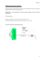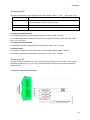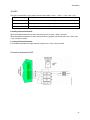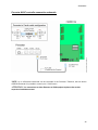
1
SYSTEM VERSION 2.5xx Installer’s guide LIMITED WARRANTY .................................................................................................... 1 INSTALLATION PROCEDURE ...................................................................................... 3 PRIOR TO THE INSTALLATION ...........................................................................................................................4 1- SECURITY EQUIPMENT INSTALLATION ....................................................................................................................5 2- TOUCH PANEL AND KEY READER INSTALLATION ....................................................................................................5 3- TEMPERATURE CONTROL INSTALLATION ................................................................................................................5 4- CONTROL MODULE INSTALLATION (LIGHT, LOAD, SHADE) IF ANY..........................................................................5 5- X-10 COMPATIBLE MODULE INSTALLATION (IF ANY) .............................................................................................6 6- TELEPHONE INSTALLATION (TOUCHTONE ONLY)....................................................................................................6 7- CARDIO IIÉ CENTRAL CONTROLLER INSTALLATION .............................................................................................6 8- CARDIO IIÉ PROGRAMMING .................................................................................................................................6 ADVANCE CONFIGURATION ....................................................................................... 7 ZONES TYPES ..............................................................................................................................................................8 DELAY ........................................................................................................................................................................9 SOS............................................................................................................................................................................9 SUN ..........................................................................................................................................................................10 MONITORING ............................................................................................................................................................11 ZONE REPORT. CODES ...............................................................................................................................................11 SYSTEM REP. CODES.................................................................................................................................................12 TEMPERATURE .........................................................................................................................................................12 Central heating system ........................................................................................................................................14 Heat pump system ................................................................................................................................................14 HVAC System.......................................................................................................................................................15 HVAC setback......................................................................................................................................................16 Heating setback ...................................................................................................................................................17 SYSTEM RESTORE ..................................................................................................... 18 TO PERFORM A SYSTEM RESET ..................................................................................................................................18 TO PERFORM A RESTORE TO FACTORY DEFAULT .......................................................................................................18 MODIFICATION / LOSS OF INSTALLER CODE ..............................................................................................................18 TROUBLESHOOTING.................................................................................................. 19 PROTECTION .............................................................................................................................................................19 Battery protection ................................................................................................................................................19 LED outputs (digital keys.) ..................................................................................................................................19 External devices...................................................................................................................................................19 Telephone protection ...........................................................................................................................................19 Bus (SNet) protection...........................................................................................................................................20 Relay protection...................................................................................................................................................20 Security input protection......................................................................................................................................20 Digital key input protection .................................................................................................................................20 X-10 interface protection.....................................................................................................................................20 TELEPHONE ..............................................................................................................................................................21 No tone from local (inside) telephone..................................................................................................................21 No tone only when connecting CARDIO’s telephone cable into the RJ31X. .......................................................21 RJ31X (CA38A in Canada)..................................................................................................................................21 CARDIO and an answering machine...................................................................................................................21 Number of telephone............................................................................................................................................21 Type of telephone.................................................................................................................................................22 Central monitoring station ..................................................................................................................................22 CARDIO cannot take the telephone line..............................................................................................................22 Important noises when using a telephone............................................................................................................22 X-10.........................................................................................................................................................................23 No control from screen ........................................................................................................................................23 Make the good choice of module .........................................................................................................................23 Modules for incandescent light only ....................................................................................................................23 Electronic transformers .......................................................................................................................................24 Only one light cannot be controlled ....................................................................................................................24 TEMPERATURE CONTROL (FROM CARDIO’S THERMOSTAT ONLY) .................................................................25 Nothing works......................................................................................................................................................25 How to check CARDIO relays .............................................................................................................................25 Central heating systems.......................................................................................................................................25 Low temperature thermostat................................................................................................................................26 Only one sub-system does not work.....................................................................................................................26 The touch screen does not show the right temperature........................................................................................26 Quick cycling of the temperature control system.................................................................................................26 SECURITY .................................................................................................................................................................27 Door/window contacts not changing status.........................................................................................................27 Detector not changing status when triggered......................................................................................................27 A smoke detector “beeps” with no good reasons ................................................................................................27 The siren does not work.......................................................................................................................................27 General specifications of detectors that can be connected to CARDIO ..............................................................28 Color code ...........................................................................................................................................................28 Types of smoke detectors .....................................................................................................................................28 End-of-line-resistance..........................................................................................................................................28 Siren output..........................................................................................................................................................28 SECANT PERIPHERICAL PRODUCTS AND BUS. ............................................................................................29 None of the products is functioning .....................................................................................................................29 If battery unplugged or discharged .....................................................................................................................29 Only some products work properly......................................................................................................................29 Only one item does not work ...............................................................................................................................29 “Communication problem” message in CARDIO’s logbook ..............................................................................29 How to install the bus ..........................................................................................................................................30 Bus checking ........................................................................................................................................................30 Peripheral items checking ...................................................................................................................................30 Bus polarity..........................................................................................................................................................30 LED STATUS ............................................................................................................................................................31 SCHEMATICS .............................................................................................................. 32 INSTALLATION SCHEMATICS ..........................................................................................................................32 Touch panel installation ......................................................................................................................................32 Key reader installation ........................................................................................................................................32 Central controller installation .............................................................................................................................33 CONNECTIONS SCHEMATICS ...........................................................................................................................34 Peripheral connection schematic.........................................................................................................................34 Key reader (EKRa) connection schematic...........................................................................................................35 Touch screen (TP2B) connection schematic........................................................................................................36 TP2B Master/Slave configuration .......................................................................................................................37 TP2B contrast adjustement..................................................................................................................................38 Heating system connection schematic .................................................................................................................39 1) Central heating............................................................................................................................................39 2) Heat pump RH .............................................................................................................................................40 3) Heat pump RC .............................................................................................................................................40 4) HVAC ..........................................................................................................................................................41 5) HVAC setback .............................................................................................................................................42 6) Heating setback ...........................................................................................................................................43 Proverter HVAC controller connection schematic ..............................................................................................44 Telephone connection schematic .........................................................................................................................45 ADSL filter connection schematic........................................................................................................................46 Telephone menu...................................................................................................................................................47 PC to CARDIO connection schematic .................................................................................................................48 INDUSTRY CANADA WARNINGS............................................................................... 49 Limited warranty Limited warranty We appreciate your purchase of a Secant Home Automation Inc. product. We take pride of our products and they are manufactured according to strict quality standard. We feel confident that in normal use they will provide you with satisfactory performance. However, should you experience difficulty you are protected under the provisions of this warranty. Secant Home Automation Inc. product provided under this purchase is a control device of the user’s home facilities. Its successful use and operation is dependent on the skill of the operator of the device. It is possible to incur faulty performance, such as poor lighting, false alarms or insufficient heating or air conditioning by giving inappropriate commands or instructions to the control device. Accordingly, read carefully all the instructions contained in this guide before operating this Secant Home Automation Inc. product. THIS WARRANTY IS VALID FOR RESIDENTIAL USE ONLY SECANT HOME AUTOMATION INC. DOES NOT WARRANT THAT THE FUNCTION CONTAINED IN THE SOFTWARE/HARDWARE WILL MEET YOUR REQUIREMENTS OR THAT THE OPERATION OF THE SOFTWARE/HARDWARE WILL BE UNINTERRUPTED OR ERROR FREE. HOWEVER, SECANT HOME AUTOMATION INC. WARRANTS THE HARDWARE ON WHICH THE SOFTWARE IS FURNISHED TO BE FREE FROM DEFECTS IN MATERIAL AND WORKMANSHIP UNDER NORMAL USE AND SERVICE FOR A PERIOD OF THREE (3) YEARS FROM THE DATE OF PURCHASE EXCEPT FOR THE LCD/TOUCH SCREEN COMBINATION FOR WHICH THE PERIOD IS ONE (1) YEAR. REPLACEMENT PARTS, FURNISHED IN CONNECTION WITH THIS WARRANTY SHALL BE WARRANTED FOR A PERIOD EQUAL TO THE UNEXPIRED PORTION OF THE ORIGINAL EQUIPMENT WARRANTY. ALL SECANT HOME AUTOMATION INC. PRODUCTS ARE ONLY WARRANTED TO THE ORIGINAL RETAIL PURCHASER. THIS WARRANTY BECOMES VOID IN THE EVENT SERIAL NUMBERS ARE ALTERED, DEFACED OR REMOVED. THE DEALER’S ORIGINAL DATED INVOICE SHOULD BE RETAINED AS PROOF OF PURCHASE AND MUST BE PRESENTED, TOGETHER WITH THIS WARRANTY, TO THE INSTALLER WHEN THIS PRODUCT IS TO BE SERVICED UNDER THE PROVISIONS OF THIS WARRANTY. SECANT HOME AUTOMATION INC WILL REPAIR OR REPLACE, WITH ITS DISCRETION, THE PRODUCTS WHICH WILL HAVE BEEN FOUND DEFECTIVE AND RETURNED OVER ACCORDING TO TERMS’ OF THIS WARRANTY. THIS WARRANTY DOES NOT COVER THE COSTS OF DISPLACEMENT AS WELL AS THE COSTS OF LABOR TO WITHDRAW AND REINSTALL ANY DEFECTIVE COMPONENT, THIS RESPONSIBILITY FALLS TO THE INSTALLER. THE TRANSPORTATION CHARGES OF THE PRODUCT ARE THE RESPONSIBILITY OF THE OWNER. THE WARRANTY SHALL APPLY TO SECANT HOME AUTOMATION INC. PRODUCTS PURCHASED FROM AN AUTHORIZED DEALER, AGENT AND/OR REPRESENTATIVE. THIS WARRANTY SHALL NOT APPLY TO DAMAGE DUE TO HANDLING, TRANSPORTATION, UNPACKING, INSTALLATION, ANY DEFECTS CAUSED OR REPAIRS REQUIRED AS A RESULT OF NOT FOLLOWING THE INSTRUCTIONS IN THE USER’S MANUAL, REPAIR OR REPLACEMENT OF PARTS SUPPLIED BY OTHER THAN SECANT HOME AUTOMATION INC. AUTHORIZED DEALERS, ANY MALFUNCTION OF FAILURE CAUSED BY OR RESULTING FROM ABNORMAL ENVIRONMENTAL CONDITIONS, IMPROPER UNAUTHORIZED SERVICE, IMPROPER MAINTENANCE, MODIFICATIONS OR REPAIR BY THE CONSUMER, ABUSE, MISUSE, NEGLECT, ACCIDENT, FIRE, FLOOD, OR OTHER ACTS OF GOD, AND INCORRECT LINE VOLTAGE. THIS WARRANTY SHALL NOT APPLY TO OTHER PRODUCTS NOT MANUFACTURED BY SECANT HOME AUTOMATION INC. SUCH AS ALARM DEVICES, HEATING / COOLING SYSTEMS OR LIGHTING CONTROLS, THEIR INSTALLATION AND THEIR FUNCTIONING. FOR ANY AND ALL AND ANY OF THOSE PRODUCTS, THE USER SHALL REFER TO THE WARRANTY OFFERED BY EACH OF THEIR SPECIFIC MANUFACTURER. 1 Limited warranty THE SOFTWARE, HARDWARE, AND DOCUMENTATION IS PROVIDED “AS IS” WITHOUT WARRANTY OF ANY KIND, EITHER EXPRESS OR IMPLIED, BUT NOT LIMITED TO THE IMPLIED WARRANTIES OF MERCHANTABILITY AND FITNESS FOR A PARTICULAR PURPOSE. SECANT HOME AUTOMATION INC. RESERVES THE RIGHT TO MAKE CHANGES IN DESIGN OR TO MAKE ADDITIONS TO OR IMPROVEMENTS UPON ITS PRODUCTS WITHOUT INCURRING ANY OBLIGATION TO INSTALL THE SAME ON PRODUCTS PREVIOUSLY MANUFACTURED. NO LIABILITY FOR CONSEQUENTIAL DAMAGES. TO THE MAXIMUM EXTENT PERMITTED BY APPLICABLE LAW, IN NO EVENT SHALL SECANT HOME AUTOMATION INC OR ITS SUPPLIERS BE LIABLE FOR ANY SPECIAL, INCIDENTAL, INDIRECT, OR CONSEQUENTIAL DAMAGES WHATSOEVER (INCLUDING, WITHOUT LIMITATION, DAMAGES FOR LOSS OF BUSINESS PROFITS, BUSINESS INTERRUPTION, OR ANY OTHER PECUNIARY LOSS) ARISING OUT OF THE USE OF OR INABILITY TO USE THE SOFTWARE PRODUCT AND ACCOMPANYING HARDWARE EVEN IF SECANT HOME AUTOMATION INC HAS BEEN ADVISED OF THE POSSIBILITY OF SUCH DAMAGES BECAUSE SOME STATES AND JURISDICTIONS DO NOT ALLOW THE EXCLUSION OR LIMITATION OF LIABILITY FOR CONSEQUENTIAL OR INCIDENTAL DAMAGES, THE ABOVES LIMITATION MAY NOT APPLY TO YOU. THE FOREGOING IS IN LIEU OF ALL OTHER WARRANTY EXPRESSED OR IMPLIED INCLUDING WARRANTIES OF MERCHANTABILITY OR FITNESS FOR A PARTICULAR PURPOSE AND SECANT HOME AUTOMATION INC. NEITHER ASSUMES NOR AUTHORIZES ANY PERSON TO ASSUME FOR IT ANY OTHER OBLIGATION OR LIABILITY IN CONNECTION WITH THE SALE OR SERVICE OF ITS PRODUCTS. ACCORDINGLY, ADDITIONAL STATEMENTS IN ADVERTISING, PRESENTATIONS, DEMONSTRATIONS OR ELSEWHERE, WHETHER VERBAL OR WRITTEN, DOES NOT CONSTITUTE WARRANTIES BY SECANT HOME AUTOMATION INC. AND SHALL NOT BE RELIED UPON. NO OTHER WARRANTIES. TO THE MAXIMUM EXTENT PERMITTED BY APPLICABLE LAW, SECANT HOME AUTOMATION INC AND ITS SUPPLIERS DISCLAIM ALL OTHER WARRANTIES, EITHER EXPRESS OR IMPLIED, INCLUDING, BUT NOT LIMITED TO, IMPLIED WARRANTIES OF MERCHANTABILITY AND FITNESS FOR A PARTICULAR PURPOSE, WITH REGARD TO THE SOFTWARE PRODUCT AND ACCOMPANYING HARDWARE. THIS LIMITED WARRANTY GIVES YOU SPECIFIC LEGAL RIGHTS YOU MAY HAVE OTHERS, WHICH VARY FROM STATE/JURISDICTION TO STATE/JURISDICTION. THE PURCHASER MAY HAVE OTHER RIGHTS UNDER EXISTING STATE OR FEDERAL LAWS, AND WHERE ANY TERMS OF THIS WARRANTY ARE PROHIBITED BY SUCH LAWS, THEY ARE DEEMED NULL AND VOID, BUT THE REMAINDER OF THE WARRANTY SHALL REMAIN IN EFFECT. 2 Installation procedure Installation procedure The following is a suggested installation procedure for installing CARDIO and its peripheral items. We assume that installers have a good knowledge of security system and their equipments, heating/cooling systems and lighting controls equipments. ATTENTION!: All wiring must comply with local and national electrical codes and ordinances of the country to which the system is being installed. INCLUDED IN THE BOX CARDIO IIé central controller 1 touch panel with temperature sensor 1 digital key reader 2 electronic keys 1 Telephone cable 1 X-10 cable Screws and anchors NECESSARY EQUIPMENTS (not included) 16Vac power supply (50Va min, 250Va Max.) Rechargeable battery 12V 7AH Alarm detectors and contacts Smoke and heat detector Siren Doorbell (with transformer) RJ31X (CA38A in Canada) for telephone line ADSL in line filter (if necessary) Lighting control equipments (if necessary) X-10 module (if necessary) NECESSARY TOOLS Digital multimeter Plier Wire cutter Skinner Flat screwdriver RJ45 & RJ11 crimper tools HEX screwdriver 3 Installation procedure PRIOR TO THE INSTALLATION 9 Perform 9 9 9 9 a complete analysis of the needs for each of the main functions (security, temperature, heating/cooling and lighting control); Read carefully and keep close to you the technical notice and instruction sheet of all products to be installed with the system; Set up a complete and detailed wiring layout; If CARDIO is to be hooked up to a central monitoring station, make sure that this provider accepts one of the two protocols available (see p.11); Make sure to get a double power supply outlet near the installation dedicated to CARDIO and the X-10 TW523 module (if needed). SUGGESTIONS ¾ ¾ ¾ ¾ ¾ Do not discard the specification and instruction sheets of any installed products Keep a layout of the installation and a list of all installed items Keep a copy of the programming Keep a note of the system passwords for future reference For more complex installation ( ex. with many lighting channels) keep a detailed listing of all equipments installed with channels and buttons location etc. For future reference, we suggest that you write down the following information’s: CUSTOMER NAME: ____________________________________________ SYSTEM SERIAL NUMBER: ______________________________________ SYSTEM VERSION: ___________________________________________ INSTALLER PASSWORD: ________________________________________ 4 Installation procedure 1- Security equipment installation 1) Select alarm detectors and sensors according to needs and location. 2) Check correct location of all security equipment and install them. 3) Wire all security devices to the CARDIO controller (do not make connection yet). 4) Installation and connection of doorbell and siren. 5) Individual testing of security sensor (use an Ohmmeter and a battery). 2- Touch panel and key reader installation 1) Check correct location of touch panel(s) and electronic key reader(s) and install them. 2) Wire the SNet Bus for the touch panel and the digital key readers (see schematic section p.36). 3) Check the bus for short or problem (see troubleshooting section p.30) ATTENTION!: for the bus wiring, we strongly recommend to use a twisted pair of wire from a cable No 18awg unshielded (CAT-5 or 5e). 3- Temperature control installation 1) Check the kind of heating/cooling system to be connected to CARDIO (refer to their respective technical notice for proper installation and connection). 2) Install relays, safety thermostats, etc. 3) Connect high/low voltage wiring to relays, thermostats, etc. (see schematics section for each type of heating system). 4) Check functionality of the heating/cooling system before connecting to CARDIO. 4- Control module installation (light, load, shade) if any. 1) Check loads to be controlled (type, power) and their respective specifications. 2) Check the kind of control module to be connected to CARDIO. (see their respective technical notice for proper installation and connection). 3) Install control module and switches. 4) Wire high and low voltage for the module and switches. 5) Wire the communication Bus for the module to CARDIO. 5 Installation procedure 5- X-10 compatible module installation (if any) 1) Check loads to be controlled (type, power) and their respective specifications 2) Codes and install all X-10 modules. 3) Local testing of each module (toggle switch on module (ON/OFF/DIM)) NOTE: Test each module from the very same outlet as the TW-523 using an X-10 compatible remote control. Select proper house-code on the remote for this purpose. 6- Telephone installation (touchtone only) 1) Install the RJ31X (CA38A) between CARDIO and the home telephone line 2) If there is an ADSL internet connection in the house, install the ADSL filter between CARDIO and the RJ31X module 7- CARDIO IIé central controller installation 1) Install (but not connect) the central controller and its transformer. 2) Connect the SNet bus. 3) Turn the home main breaker OFF. 4) Connect the transformer and the battery. 5) Turn the home main breaker ON (the full system is now operating, the screen lights up and the countdown starts running. 6) Turn the home main breaker OFF again. 7) Connect all temperature wires on motherboard. 8) Connect all security wires on motherboard. 9) Plug CARDIO’s X-10 control wire (4-wire type of telephone cable) into the TW523 module (if any). 10) Plug CARDIO’s telephone cable (8-wire type of cable) into the RJ31X (CA38A). 11) Turn the home main breaker ON and do a system restore (see restore section). 8- CARDIO IIé programming Once CARDIO and all its peripheral units installed, it is time to proceed with the programming. Go through the following pages to set-up the system configuration. Please note that it is important to perform a good programming to ensure proper functioning of CARDIO and its peripherals. NOTE: For any trouble or problem, please refer to the troubleshooting section at the end of this manual. 6 Advance configuration Advance configuration The installer (advanced user) code gives access to a broader array of configuring data. For configuring functions available to any user, please refer to the CARDIO 2é User’s Guide. See below all functions available to the installer (advanced user) to configure the system. The first pages of functions are also available to entry level users, albeit sometimes in a shorter form (codes, delays) The advanced user menu is also available from the programming screen after entering the installer code (the default installer code is 00000) From the programming menu press The following screen appears: Go to CODES to modify the installer code. 7 Advance configuration Zones types CARDIO offers 16 programmable security inputs of 9 different types. • Delay: relevant to detectors associated with an entry delay (door, etc.) • Instant/delay (follower): relevant to detectors which can be triggered after a delay. For instance, the front door has a contact and a motion detector has been installed in the lobby and set up with “instant delay”. If someone enters through the door (which is the normal way to enter a house), both the contact and the motion detector will wait until the delay has expired before sending out an emergency. In the case someone enters the house through a window (which is not the normal way to enter a house), the door contact will not be triggered but the motion detector will. In this case, there is no delay attached to it and the system will send out an emergency call instantaneously. • Instant: there will be no time delay when a detector is triggered and an alarm will be sent out immediately. • 24hrs : (tamper) when a detector has to be armed continuously (24h/day) and cannot be armed or disarmed from the screen or digital keys. • Interior: once again, we will use our previous example with a contact and a motion detector associated with the “interior” status in this case. If someone inside the house turns the security ON, the system will go through the exit delay before arming the security. If the person does not exit the house before the end of the delay, the door contact will be armed but not the motion detector. This means that this person will be able to stay in the house while protected from the outside (with the door contact). • Inactive: when a zone is entered as inactive, it is inactive for security purposes only but can be used for reaction (occupancy) purposes (see User’s Guide). • Fire: to declare a fire zone. • Medical: to declare a medical zone. • Panic: to declare a panic zone. For each zone, choose from: EOL (end of line resistor), NO (normally open) and NC (normally close). When there is no end-of-line resistor installed, it is mandatory to declare either NO or NC. For each zone, choose from 1 (Yes/No) can activate the siren or not 2 (Yes/No) can be bypassed or not. Zones declared as panic, 24hrs, fire and medical cannot be bypassed, whatever data entered in the bypass column (2). 8 Advance configuration Delay Enter the maximum loop opening delay before an alarm is triggered. Values can run from 50 ms to 990 ms with increments of 10 ms. SOS • SOS hold up(yes/no): whether the siren is activated with the SOS hold up button • SOS fire (yes/no): whether the siren is activated with the SOS fire button • SOS medical (yes/no): whether the siren is activated with the SOS medical button • Active (yes/no): to momentarily disable each of these SOS functions. When entering no, this SOS function will no longer be active from the screen. 9 Advance configuration Sun • Daylight saving (yes/no): to let the system automatically switch from Standard time to Daylight saving time (and reverse) at appropriate dates. • Longitude (+/- 0..180): the distance east (-) or west (+) measured in degrees/minutes from the meridian of Greenwich. • Latitude (+/-0..90): the distance north (+) or south (-) measured in degrees/minutes from the equator. NOTE: CARDIO can control lights or outlets according to sunrise and sunset. Sunrise and sunset times are displayed on screen along with date and time. Sunrise and sunset times vary according to the location on earth. Therefore, for the time to be accurate, it is important to enter longitude and latitude data corresponding to the exact location of the system. • Time zone (+/-hrs Standard time): from the meridian of Greenwich/GMT. Locations east of the meridian of Greenwich should be entered with a positive sign while locations west of the meridian of Greenwich should be entered with a negative sign (see below for American time zones/standard time): Canada (Quebec) = +5hrs Western Europe = +1hrs • Sunrise offset (+/-min): to fine-tune sunrise time according to the customer’s needs. For example, official sunrise time at a particular date is 7am upon longitude and latitude data but for particular reasons the user feels that this time is not appropriate (it is still too dark for example). Therefore, there is a way to adjust sunrise time (+/- 0..99 minutes): entering +20 will move the sunrise time to 7:20 am. • Sunset offset (+/- min): to fine-tune sunset time (see sunrise offset for details) Sunrise/sunset times resulting from the above inputs will be appearing in the main screen in alternate with the date and time. 10 Advance configuration Monitoring • Client code: up to 2 client codes • Monitoring phone number: up to 2 different phone numbers. • Protocol: 2 protocols to choose from: SESCOA FAST (20pps) for fast transmission or ADEMCO SLOW (10pps) for slow transmission. Format can be either 3/1, 3/2 or 4/1. Zone report. codes • Alarm/restore: the first column is used to enter alarm codes while the second column is used to enter restore codes. Check with the monitoring station for specific values of these alarm/restore codes. 11 Advance configuration System rep. Codes. • Restore: restore codes are given by the monitoring station for each type of alarm. For other codes and test time, check with the monitoring station. Temperature NOTE: Note that temperature settings below and on the following pages refer to CARDIO’s built-in thermostat only. CARDIO is also compatible with RCS (ZNCR controller) and Aprilair (Enerzone) products for HVAC zoning. For technical information on these thermostats and their controllers, please refer to their respective manufacturer. ATTENTION!: Installers and users must know the functioning of heating/cooling systems. Furthermore, CARDIO will never make up for any shortcoming of a heating/cooling system. • Temperature unit: choose from degree Celsius or Fahrenheit. 12 Advance configuration • Temperature offset: because of the particular location of the touch panel, the temperature at the thermostat may vary from the average zone temperature. Therefore it is possible to adjust the reading displayed on screen (or on the phone). The maximum temperature compensation is +/- 9.9 degrees Celsius or Fahrenheit. Ex: a thermostat has been installed in a central location near the kitchen. With no compensation, the temperature reading (the exact temperature) at this location is 70F while the average temperature in the dining room and the living room is 72F. If the temperature the user wants to read and monitor (schedules, scenes, etc.) is the temperature in the living room, just enter +2. Therefore, the screen will display 72 instead of 70. ATTENTION!: the temperature control performed by CARDIO is based on the temperature offset. Therefore it is very important to set this parameter correctly. • Hysteresis: used mainly with heating/cooling system based on pulsed air. Say that the screen is located in a central location but near a heating/cooling bay. With no adjustment, the temperature read at the screen will always get to the desired temperature much before the average temperature in the room. Then, the heating/cooling system would always be turned ON/OFF (cycling) on a very short time basis before the average room temperature is reached. Adjusting the system gives more inertia to the temperature control. Maximal temperature adjustment goes from +/-0.1 degree Celsius or Fahrenheit to +/- 42 2.9 degrees Celsius or Fahrenheit. Temperature readings on screen will always be the exact temperature as read by the thermostat. Then, with a 2F adjustment, temperature readings will go to 74F before the system turns off the heat if the desired setting is 72F. • CARDIO control type: select the type of heating (cooling) system to be controlled by CARDIO: 1. 2. 3. 4. 5. 6. 7. 8. Central heating: Heat pump RC: HVAC: Heating setback: HVAC setback: Heat pump RH: Heat/cool: None: • Secondary controller: when available, choose from RCS or Statnet HVAC controllers. Also, enter number of secondary zones to be controlled (1 with RCS and up to 4 with Statnet). Do not include here the zone controlled by CARDIO’s thermostat. • Zone name: press EDIT and enter name of zones (up to 5) to be controlled. • Freeze detection (yes/no): is CARDIO to detect a minimum temperature and send out an alert? (see temperature setting below) • Overheat detection (yes/no): is CARDIO to detect a maximum temperature and send out an alert? (see temperature setting below) • Freeze temperature: enter the minimum temperature threshold. • Overheat temperature: enter the maximum temperature threshold. !WARNING!: DO NOT USE CARDIO FOR FREEZE PROTECTION. We strongly recommend to install an auxiliary mechanical freeze protection for this purpose. 13 Advance configuration Central heating system Usually made up of a furnace and a two-wire thermostat (R and W). Installed in a central location, this thermostat controls only one zone. When multiple zones is declared a button named OTHERS appears on each screen. Press successively on this button to have access to desired zones. Heat pump system CARDIO can control most heat pump heating systems. Still, CARDIO cannot control heat pumps with thermostats managing more than compressor, valve, blower and auxiliary heating. 14 Advance configuration HVAC System Made up of two separated items, a furnace and a cooler, controlled by a single thermostat with two set points. Four modes of operation (none, heating only, cooling only and automatic) and fan control (automatic, manual). CARDIO in the HVAC settings can substitute this thermostat. ATTENTION!: its is impossible to have both heating and cooling at the same time in the HVAC mode. There is always a 2-degree minimal difference between the two settings and CARDIO will adjust automatically if necessary. 15 Advance configuration HVAC setback Usually made up of two separate items: a heating system (furnace, baseboard heaters, etc.) and a cooling system. Two types of control: heating and cooling with fan control when available. The main difference between HVAC/setback and HVAC is that in the case of HVAC, heating and cooling modes are integrated into one system while in the case of HVAC/setback, heating and cooling modes are two separate entities. ATTENTION!: it is impossible to have both heating and cooling at the same time in the HVAC mode (there is a built-in 2-degree minimum difference) but this may occur with the HVAC/setback mode because heating and cooling are two separate units. Therefore temperature and the functioning of the two systems may overlap if the user does not pay attention to it. 16 Advance configuration Heating setback This is the type of control when the heating system is made of baseboard heaters only. Each zone (room) has its own basic thermostat which will be set manually to the normal temperature (comfort temperature) according to the user’s needs. CARDIO will take control of all zones when in economic mode only and the temperature will be the one entered in the “desired temperature” setting in the screen below. Example: normal/comfort (adjusted manually on each local thermostats) Living room 21 Bedroom 1 19 Bedroom 2 18 Desired temperature (economy): 16 (set on the screen in the upper right corner) 1. From the screen, when pressing “normal”, temperature will be set at the comfort temperature adjusted manually by the user in each zone (21, 19 and 18 respectively in the living room, bedroom 1 and bedroom 2 in the above example). 2. From the screen (or from the phone), when pressing “economy”, the temperature will be 16 in all zones. 17 System restore System restore There are two push buttons on the lower parts of the central controller printed circuit board (inside the metal box). One (RESET) is used to reboot the system. The other one (PGM) is used to perform a restore to factory default settings. To perform a system reset 1. Push the (RESET) button once. The system will reboot and enter a 30 second delay. To perform a restore to factory default 1. Push the (RESET) button once. The system will reboot and enter a 30 second delay. Go to the Secant touch screen during this 30 second delay. 2. At the end of the 30 second delay, a countdown appears on the screen to allow the entry into diagnostic mode. Touch the screen during this countdown and the system enters into diagnostic mode. (To check if you really entered into diagnostic mode, you are supposed to see all the 16 alarm zones with their current status and the system voltage on the screen.) 3. Once the system is in diagnostic mode, go back to the central controller and push 6 times on the (PGM) button. The system now comes back to factory default and a message appears on screen. !WARNING!: A system restore to factory default will completely erase all the programming of the system. Modification / Loss of installer code The installer code by default is 00000. It is possible to modify it on the CODE section of the programming screen after entering the current valid installer code. Once the installer code has been modified, should it be lost, the only way to enter again on the installer advance programming menu will be to perform a restore to factory default (see above). !WARNING!: by doing a system restore, the installer code will automatically come back to its original value (00000) AND all the system programming will be erased! NOTE: The installer code is not valid to disarm the security function. 18 Troubleshooting Troubleshooting This chapter addresses troubleshooting of the CARDIO system. Please note that even if CARDIO is connected to products made by other manufacturers, we do not offer support for the non-SECANT products. Therefore, always keep instructions and specifications of non-SECANT products for future reference and contact their respective manufacturer for support. Protection Battery protection To protect the central controller in case the battery be connected with reverse polarity, the device used is a 3 Amp. POLYSWITCH*. This POLYSWITCH* will be in a high impedance state if the current powering the system is higher than 3 Amp. 1. red wire: positive 2. black wire: négative LED outputs (digital keys.) To protect the driver of each LED, a POLYSWITCH* RT5 will limit the total current at the two outputs to 100mA. The POLYSWITCH* will be in a high impedance state if the current is higher than 100mA when 1. there is a short; 2. there are too many LED’s External devices To limit the total current used by all external devices such as touch panels, security detectors, siren, etc. The protection is a 1.1 Amp. POLYSWITCH*. The POLYSWITCH* will be in a high impedance state when the current is higher than 1.1 Amp. At this time the LED D14 located in the upper right corner of the board will turn on. 1. there is a short in wiring; 2. the siren is defective; 3. the siren output is too high (30W max.); 4. the touch panel is defective. Telephone protection To protect the central controller from lightning’s and other high potential noises. POLYSWITCH* RT3 and RT4 along with SIDACTOR* SD1 will limit the energy to 300V. 19 Troubleshooting Bus (SNet) protection To protect the central controller against noise, lightning and shorts that may occur on the bus. POLYSWITCH* RT1 and RT2 along with TRANZORB* TZ1 and TZ2 will limit the energy at the bus input. Relay protection All relay contacts are protected by a 35V RMS metal Oxide varistor. Still it is highly recommended to limit any source voltage applied to these relays to 24 RMS. • Maximum contact current is 3 Amp for all relays. Security input protection For each of the 16 inputs, there is a resistor and a TRANZORB* that together will limit the voltage at 5V. Normal operation of these inputs is a current loop to ground. Maximum voltage that can accidentally applied at each input without causing any damage is 12V. There is another protection (LC lowpass filter) against high frequency noises picked up by wires. Digital key input protection A POLYSWITCH* and a TRANZORB* will limit the voltage to 5V. X-10 interface protection Inductors and Zener diodes will limit noises coming from the TW523. * POLYSWITCH, TRANZORB and SIDACTOR are registered trademarks of their respective manufacturer. 20 Troubleshooting Telephone No tone from local (inside) telephone • Check if all cables are correctly connected: 1. CARDIO’s telephone cable connected into the digital communicator module RJ31X; 2. the home’s telephone line into the RJ31X; 3. the wire of the internal telephone network into the RJ31X. • Check that the RJ31X (CA38A in Canada) is of the right type. • If all connections are good, disconnect CARDIO’s telephone cable from the RJ31X. Open the RJ31X and check voltage reading is 45Vdc between pins 4 and 5 of the RJ31X 1. If yes, check if voltage is 45Vdc between pins 1 and 8 of the RJ31X. If yes, the internal telephone network is cut. If not, replace RJ31X. 2. If not, the home telephone entry line is not connected or this line is cut. No tone only when connecting CARDIO’s telephone cable into the RJ31X. 1. check the connection of the telephone cable on the CARDIO’s main board; 2. check this cable; 3. do a “reset”: if there is no change, CARDIO is defective. 4. the touch screen is defective RJ31X (CA38A in Canada) CARDIO comes with a flat telephone cable made up of 8 wires as well as a circuit that “cut” the telephone line in case of an emergency call. It is mandatory that this cable be connected to a compatible jack where connections between the home main telephone line, CARDIO and the home local telephone network are correct. Contact your local telephone company if you have any doubt about the correct wiring of this plug CARDIO and an answering machine If there is an answering machine on the same telephone line as CARDIO, check the programming in the Configuring menu (telephone). It should be as follow: 1. Rings after answering: always enter a number of rings higher than that of the answering machine. 2. Answering machine: YES Number of telephone Only one telephone can communicate with CARDIO. The use of more than one telephone at the same time will lower signals and impede the good functioning of CARDIO. 21 Troubleshooting Type of telephone CARDIO can communicate with Touch-Tone telephones only. Central monitoring station When activating the account: 1. check the “Monitoring” menu in Advance configuration if the monitoring station’s telephone number has been entered as well as the protocol used and the customer’s code; 2. check also alarm codes in the “Alarm code” menu in Advance configuration. NOTE: If only one of the above data is not entered correctly, the monitoring station will be unable to monitor the home. CARDIO cannot take the telephone line 1. check if telephone numbers have been entered in the Telephone Configuration menu; 2. if the telephone network seems fine, change CARDIO. Important noises when using a telephone These noises could come from two different sources: • from CARDIO’s power supply if it is overloaded; • from a noise running in the Earth ground (green wire): 1. Disconnect the ground wire and check if the noise is still here; 2. if yes, remove loads from CARDIO’s central controller; 3. if not, localize the source of this noise and reconnect the green wire. 22 Troubleshooting X-10 No control from screen We take for granted that all local tests described in the installation process have been achieved i.e.: 1. all modules can be controlled successfully from a X-10- compatible remote control plugged in the very same outlet as the TW-523. 2. check that the TW-523 is plugged, that its LED is ON and that the telephone type cable (4 wires) is plugged into the TW523 and in the central controller. When you try to modify a lamp status from the screen and the TW-523 does not flash, just plug another TW-523 in the adjacent outlet and try again. Leave the cable coming from CARDIO in the first TW523. With a X-10-compatible remote control plugged in the same outlet as the TW 523 and with the same House Code, change the status of a light. Check on screen if the dim has been modified accordingly: if it did change, the CARDIO X-10 interface works properly. Then: 1. check that all modules are installed properly; 2. try with another cable from CARDIO to the TW-523 module; 3. try another TW-523 module. Make the good choice of module Most of the time, bad functioning is a matter of choosing a module not compatible with the load to be controlled. Read carefully all specifications on lamps and modules. Modules for incandescent light only 1. never connect a fluorescent neon fixture or any electronic transformer for halogen lighting.; 2. maximum load on a same module should not be higher than 66% of specified maximum load in module specifications.; 3. minimum load on a same module should not be lower than specified information in specifications (usually 60W but check with modules manufacturer). 4. be careful with number of lights connected to the same module. ‘Ganging” increases the inrush current and can use-up the module quickly. 23 Troubleshooting Electronic transformers Very often, halogen lights are sold with a built-in electronic transformer. The electronic circuit of this transformer is no less than a short circuit for X-10 commands. Installing such a device will create many problems: 1. the module controlling this light will not always receive X-10 commands; 2. when this light is ON, all other lights (connected to other X-10 modules) would not receive any X-10 commands. Only one light cannot be controlled 1. check breaker associated with this light; 2. check lamp; 3. check code; 4. check module. 24 Troubleshooting TEMPERATURE CONTROL (from CARDIO’s thermostat only) Nothing works Baseboard heaters 1. check breaker associated with baseboard heaters; 2. the transformer of heating relays (reading should be 24VAC); 3. check wiring; 4. check relays. Central heating 1. check breakers associated with the heating system; 2. check connections on terminal blocks in central controller; 3. check the relay; 4. check the power supply of the heating system. HVAC and Heat pump 1. check the system mode set in the Temperature menu in the installer configuring menu. It should correspond to this type of system; 2. check connections on terminal blocks in central controller; 3. check relays; 4. check power supply of HVAC or heat pump. How to check CARDIO relays 1. disconnect all heat control wiring at the terminal block in the the central controller; 2. connect your ohmmeter to the terminal block. If the contact is OPEN, reading should be 0. 3. from the screen, modify the desired temperature to make the relay change status. Each change of status a modification of the resistance read on the ohmmeter. If there is no change of resistance and you are sure that the temperature set point has been modify, the CARDIO relay is defective. Central heating systems When control wires are disconnected, you should read 24VAC between the “R” wire and any other wire. If not, refer to the manual of this heating system. 25 Troubleshooting Low temperature thermostat We strongly suggest that you install one thermostat used for low temperature detection (around 46 F or 8 C). Connect this thermostat in parallel with the heating relay or auxiliary heating relay. Therefore, should CARDIO be defective, there will be another security device. Only one sub-system does not work (heating or cooling or fan) 1. check connections on terminal blocks; 2. check relays, wiring and breakers associated with these systems. The touch screen does not show the right temperature For various reasons, temperature readings at the screen may differ from temperature readings elsewhere in the room. Use “compensation of the temperature” in the Temperature menu of the Installer configuring menu. Quick cycling of the temperature control system This is due to the screens being to close to heating/cooling source. 1. give more inertia to CARDIO’s temperature control sensitivity by setting the right data in “hysteresis” ( see p.13). !WARNING!: read technical specifications of relays to be installed. CARDIO’s relays only allow loads with the following characteristics: Resistive: 24VAC Inductive: 24VAC If you use relays with higher than 24VAC, protection circuits will be damaged. 26 Troubleshooting Security Door/window contacts not changing status While you consecutively open and close a contact, the system do not change status: 1. make sure that an end-of-line resistance has been connected. With an ohmmeter, check this particular security wire: resistance should be nil when the contact is closed and infinite when it is open. When the end-of line resistance is out of the central controller, the resistance should be 2200 Ohm when the contact is closed and it should be infinite when the contact is open. 2. check contact if the problem remains. Detector not changing status when triggered 1. with an ohmmeter, check that the voltage at the 12 Vdc in the central controller is around 12 or 14 volts; 2. check that you get the same voltage directly at the detector; 3. if yes, check the detector manual for trouble-shooting or change it. A smoke detector “beeps” with no good reasons 1. check voltage at the detector; 2. if it is 0 while all other detectors work properly, check wiring and connections of this particular detector; 3. if voltage is between 5 and 10 and the screen does not work, the system was working on the battery which is now discharged. Check main breaker and transformer. 4. if voltage is between 12 and 14, replace this smoke detector The siren does not work 1. check siren wire connection and polarity at the central controller; 2. remove the siren wire from the siren terminal- block on the central controller and check resistance; 3. if resistance is infinite, the siren wiring is cut or there is a bad connection on the siren or the siren is defective; 4. check connection and polarity on the siren, 5. change the siren. 27 Troubleshooting General specifications of detectors that can be connected to CARDIO • voltage: between 12 and 14 Volt DC • maximal available current for all detectors should not exceed 500 mA. For more current needs, add an independent power supply. • open loop delay: 50ms to 900ms. Color code For all security wiring, use the following color code which is usually used by professionals: • red : +12V (power) • black : 0V (power) • green : loop • yellow : loop return Types of smoke detectors Only automatic reset smoke detectors can be connected to CARDIO. Contacts can be either N.O. or N.C. Note: smoke detectors have a limited lifetime. Put in your file the type of detector that has been installed for future identical replacement. End-of-line-resistance You should install an end-of-line resistance on all security inputs unless these inputs have been declared inactive in the security menu of the installer configuring menu. Siren output CARDIO allows one 30W max. siren only. To install more sirens, connect a power relay (coil 12VDC) on the siren terminal block in the central controller. Add an auxiliary power supply to feed the sirens. 28 Troubleshooting SECANT PERIPHERICAL PRODUCTS AND BUS. Touch screen(s) and key reader(s) None of the products is functioning 1. bad connection of the BUS at the central controller or at the first item; 2. bus cable cut between the central controller and the first item. If battery unplugged or discharged 1. faulty transformer; 2. electrical panel breaker OFF. Only some products work properly 1. bad Bus connection at the first non functioning item; 2. bus cut between last functioning and first non functioning items. Only one item does not work 1. bad connection to its own wire on bus; 2. cut wire; 3. damaged product. If the product seems powered; 4. check the twisted pair associated to the communication; 5. check the “address” of this items on your layouts “Communication problem” message in CARDIO’s logbook Usually followed by an automatic RESET of the system: the central controller was unable to perform its automatic communication checking. The central controller will make 3 attempts generating 3 resets. 1. check touch screen and its connection to the bus and all bus connections if necessary. 29 Troubleshooting How to install the bus (refer to bus installation schematic) 1. wire the bus with the suggested cable; 2. leave a 10”loop out of the wall at each location 3. cut the loop 4. Skin all 8 wires (2x4) and join each color-like wires Bus checking 1. at the extremity of the bus cable to be connected to the central controller, skin all 4 wires and measure resistance between the two wires of the same pair and between a wire of each pair. In each of these two cases, resistance should be infinite. 2. then, still at the end of the bus to be connected to CARDIO, short wires of each pair and measure the resistance at the other end, that to be connected to the last item on the bus: resistance should be NIL. 3. the test is now complete. Remove shorts on the CARDIO end of the bus and leave all 4 wires open and ready to be connected to CARDIO later on. !WARNING!: Make sure to remove all short circuits.. Peripheral items checking During its countdown, CARDIO checks and displays all peripheral products on the bus. Make sure that it does read all products that have been installed. Bus polarity For all products, make sure to respect COM A and COM B: • the green wire goes to COM A • and the yellow wire goes to COM B. 30 Troubleshooting LED status There are two LEDs on the CARDIO central controller printed circuit board (inside the metal box). 1) The LED in the middle of the main board is the “Status LED”. 2) The LED in the upper right corner is the “Over current LED” 1) STATUS LED I. This LED blinks in normal operating state. II. When it is always ON either the battery is low (no battery or empty battery) or there is no AC POWER • When the problem is «low battery», a mesage appears in the logbook one minute after it is detected. Should the correct code being entered when programming CARDIO a message is sent out to the monitoring station and a pictogram appears on screen. The LED stays ON as long as the battery is not fully recharged or replaced and that the installer (advanced user) has not updated the status of the led. To update the status of the Led it is necessary to enter into the programming menu and enter the installer code. CARDIO keeps track of the «battery low» message to show that the battery jas been discharged and needs to be checked. • When the problem is «no AC power» a message appears in the logbook and a message is sent out to the monitoring station only 2 hours after it has been detected and if it has not been corrected inthe meantime. However, a pictogram showing a plug appears on screen. The LED gets back to its normal status (blinking) and the pictogram disappears when AC power gets back. III. When it is OFF there is no voltage either at the two power sources (AC or battery) or the power circuit board is defective. 2) OVER CURRENT LED I. The LED is off in normal operating state. II. It turns ON when the total consumption needs of all devices powered by CARDIO (alarm, displays, key readers, etc) exceeds 1A. When consumption gets down to a value under 1A this LED turns off after a few minutes. NOTE: CARDIO is protected by POLYSWITCH fuses (all power circuits outputs, telephone interface) These protection circuits stand out since they automatically switch on after the problem be solved. 31 Schematics Schematics INSTALLATION SCHEMATICS Touch panel installation A: Provided 4x #4-40 Hex machine screws B: Provided 4x #6 5/8 Wood screws. C: Provided 4x #6-8 Wall anchors (for use in drywall). * Suggested touch panel height from the floor. For customer’s convenience, install the touch panel at eye level. Key reader installation 32 Schematics Central controller installation D: To install the central controller use either the provided 4x #6 3/4 or the 4x #6 1”1/2 wood screws depending of the wall type to which the system is to be being installed. As an alarm system, make sure that the metal enclosure is solidly fixed to the wall. E: Only use the pre-cut knock-out either on the outside and on the inside of the metal enclosure to pass the wire. In addition, always use plastic or metal cable connectors to protect the cable from the enclosure hole edges. NEVER drill other holes in the box, if you do so, the system warranty will be void. GROUND: To fully protect the central controller, it is recommended to “ground” the system to earth using the #6-32 nut to be connected with a #14AWG wire to another wire leading to a water pipe. BATTERY: only use battery of the right type: 12V 7A/hour which should be replaced at least every two years*.NOTE: The battery should be placed in horizontal position only in order to avoid any leak that could severely damage the system. The battery may explode if it is of the wrong type. Discard used batteries according to local laws. *ATTENTION!: Note that in a region where there is a lot of electric power outages during the year, the battery could wear out much more quickly and then requires quicker replacement. 33 Schematics CONNECTIONS SCHEMATICS Peripheral connection schematic 34 Schematics Key reader (EKRa) connection schematic 35 Schematics Touch screen (TP2B) connection schematic NOTE: Use twisted pair of wires from CAT-5 or CAT-5e cable to wire the SNet Bus 36 Schematics TP2B Master/Slave configuration Follow these steps to select between master and slave mode. NOTE: The TP2B is set as "master" from factory. 37 Schematics TP2B contrast adjustement Touch panel backside view (metal enclosure removed) Contrast adjustment screw. Turn counter clockwise to increase the LCD contrast. (adjust slowly and carefully with a small screwdriver) 38 Schematics Heating system connection schematic The following section describes the different connection schematics depending on the type of heating/air conditioning selected in the "advanced configuration”. ATTENTION!: It is very important to connect the system according to the type of chosen heating system. 1) Central heating This type of temperature control system only use the relay label « Heat ». If the ambient temperature is lower than the set point, the relay « Heat » is closed. Connection schematic central heating system 39 Schematics 2) Heat pump RH This type of temperature control system uses the relays labels « Heat », « Cool », « Fan ».and « Aux ». Heat This relay is closed to control the compressor of the heating pump. Cool This relay controls the reversing valve. It is closed during the heating process and open during the cooling process. Fan This relay is closed during the heating and cooling processes Aux This relay is closed to control an auxiliary heating system (if necessary). In heating mode and Automatic If the ambient temperature is lower than the set point, the relay « Heat » is closed. If the ambient temperature is lower for more than one (1) degree from the set point, the relay « Heat » and « Aux » are closed. In cooling mode and Automatic If the ambient temperature is higher than the set point, the relay « Cool » is closed. In Auxiliary mode In this mode, the heat pump is not more used, only the auxiliary heating system is working. If the ambient temperature is lower than the set point, the relay « Aux » is closed. 3) Heat pump RC This type of system is identical to type #2. The only difference being for the use of the « Cool » relay. In opposition to system #2, the « Cool » relay is closed during the cooling process and open during the heating process. Connection schematic heat pump 40 Schematics 4) HVAC This type of temperature control system uses the relay labels « Heat », « Cool », « Fan ».and « Aux ». Heat This relay is closed to control the heating. Cool This relay is closed to control the cooling. Fan This relay is closed either during cooling and heating control processes Aux This relay is closed to control the auxiliary unit In heating mode and Automatic When the ambient temperature is lower than the set point, the relay « Heat » is closed. When the ambient temperature is lower more than three (3) degree from the set point, the « Heat » and « Aux » relays are closed. In cooling mode and Automatic If the ambient temperature is higher than the set point, the « Cool » relay is closed. Connection schematic HVAC 41 Schematics 5) HVAC setback This type of temperature control system uses the relay labels « Heat », « Cool » and « Fan ». Heat This relay is closed to control the temperature in economy mode Cool This relay is closed to control the cooling Fan This relay is closed during the cooling control process In setback mode (economy) When the ambient temperature is lower than the set point, the « Heat »relay is closed. In normal mode (comfort) The « Heat » relay is always closed, the temperature control is monitored by the thermostat*. In all modes When the ambient temperature is higher than the cooling set point, the « Cool » relay is activated. Connection schematic HVAC setback 42 Schematics 6) Heating setback This type of temperature control system only uses the relay label « Heat ». In setback mode (economy) When the ambient temperature is lower than the set point, the « Heat » relay is closed. In normal mode (comfort) The « Heat » relay is always closed, the temperature control is managed by the thermostat*. Connection schematic heating setback 43 Schematics Proverter HVAC controller connection schematic NOTE: Up to 4 Enerzone thermostat can be connected to the ProVerter. Therefore, with the built-in CARDIO thermostat it is possible to control up to 5 CVAC zones. ATTENTION!: for connections to either Enerzone or RCS equipment please refer to their respective installation manual. 44 Schematics Telephone connection schematic 45 Schematics ADSL filter connection schematic 46 Schematics Telephone menu 47 Schematics PC to CARDIO connection schematic 48 Industry Canada Warnings Industry Canada Warnings The Industry Canada Label identifies certified equipment. This certification means that the equipment meets telecommunications network protective, operational and safety requirements as prescribed in the appropriate Terminal Equipment Technical Requirements document(s). The Department does not guarantee the equipment will operate to the user’s satisfaction. Before installing this equipment, users should ensure that it is permissible to be connected to the facilities of the local telecommunications company. The equipment must also be installed using an acceptable method of connection. The customer should be aware that compliance with the above conditions may not prevent degradation of service in some situations. Repairs to certified equipment should be coordinated by a representative designated by the supplier. Any repairs or alterations made by the user to this equipment, or equipment malfunctions, may give the telecommunications company cause to request the user to disconnect the equipment. Users should ensure for their own protection that the electrical ground connections of the power utility, telephone lines and internal metallic water pipe system, if present, are connected together. This precaution may be particularly important in rural areas. ATTENTION!: Users should not attempt to make such connections themselves, but should contact the appropriate electric inspection authority, or electrician, as appropriate. The Ringer Equivalence Number (REN) assigned to each terminal device provides an indication of the maximum number of terminals allowed to be connected to a telephone interface. The termination on an interface may consist of any combination of devices subject only to the requirement that the sum of the Ringer Equivalence Number of all the devices does not exceed 5. 49 1744, William street, suite 401 Montreal, Canada, H3J 1R4 Tel: (514) 935-3069 Fax: (514) 935-6655 email: [email protected] www.secant.ca SECANT HOME AUTOMATION inc. CARDIO 2é Installer manual ft 5 edition 2008 All rights reserved