1
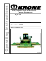
Operating Instructions
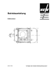
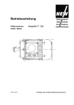
Self-propelled High-Performance
Mower-Conditioner
<v>T-yp1/Big M 400</v>
<v>T-yp2/
<v>T-yp3/
<v>T-yp4/
<v>T-yp5/
v>T-yp6</
<v>T-yp7/
<v>T-yp8/
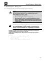
<v>T-yp9/
<v>T-yp10/
(<v>T-abMsch.Nr</from serial no.</v>: 732 378)
<v>T-BestlNr./Order no.</v>: 150 000 123 00 US
<v>B-Titelbd/
</v>
29.04.2008
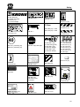
Table of Contents
Pos : 1 /BA/Inhalts verz eichnis @ 0\mod_1196861555655_78.doc @ 15165
1
Table of Contents
1
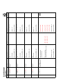
Table of Contents ................................................................................................................................... 2
2
Foreword ...............................................................................................................................................13
3
4
3.1
Introduction ...........................................................................................................................................14
Validity ............................................................................................................................................. 14
3.2
Identification Plate ........................................................................................................................... 14
3.3
Information Required for Questions and Orders.............................................................................. 15
3.4
Intended Use ................................................................................................................................... 15
3.5
Machine overview ............................................................................................................................ 16
3.6
Technical data ................................................................................................................................. 17
3.6.1
Technical Data / Vehicle .............................................................................................................. 17
3.6.2
Technical Data / Big M II CV Mower ............................................................................................ 18
3.6.3
Technical Data / Mower BIG M II CRI ......................................................................................... 18
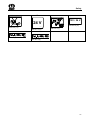
Safety .....................................................................................................................................................19
4.1
Introduction ...................................................................................................................................... 19
4.2
4.2.1
Re-Ordering the Adhesive Safety and Information Labels .......................................................... 20
4.2.2
Affixing the Adhesive Safety and Information Labels .................................................................. 20
4.2.3
Contact ......................................................................................................................................... 20
4.3
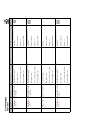
Position of the Adhesive Safety Stickers on the Machine ............................................................... 22
4.4
Position of the General Information Labels on the Machine ............................................................ 28
4.4.1
4.5
5
Identifying Symbols in the Operating Instructions ....................................................................... 32
Identification of Hazard Warnings .................................................................................................... 32
Cabin ......................................................................................................................................................33
5.1
Ladder to driver's cabin ................................................................................................................... 33
5.2
Opening the cabin door ................................................................................................................... 34
5.3
Operators controls ........................................................................................................................... 35
5.3.1
5.4
Overview ...................................................................................................................................... 35
Air comfort seat ................................................................................................................................ 36
5.4.1
Setting the left armrest ................................................................................................................. 38
5.4.2
Right armrest ............................................................................................................................... 38
5.4.3
Storage compartment for first-aid kit/operating instructions ........................................................ 39
5.4.4
Passenger seat ............................................................................................................................ 40
5.4.5
Emergency exit ............................................................................................................................ 41
5.4.6
Diagnosis socket - motor ............................................................................................................. 42
5.5
2
Identification of Hazard Warnings .................................................................................................... 19
Steering column and foot pedals ..................................................................................................... 43
5.5.1
Steering column adjustment ........................................................................................................ 44
5.5.2
Horn ............................................................................................................................................. 45
5.5.3
Indicator switch ............................................................................................................................ 45
Table of Contents
5.5.4
Full beam ..................................................................................................................................... 46
5.5.5
Headlamp flasher ......................................................................................................................... 46
5.5.6
Using the operating brake ............................................................................................................ 47
5.6
Switch group roof panel ................................................................................................................... 48
5.7
Lighting ............................................................................................................................................ 49
5.7.1
Overview ...................................................................................................................................... 49
5.7.2
Indicator, hazard warning flasher and brake light ........................................................................ 50
5.7.2.1
Switching on the indicator .................................................................................................... 50
5.7.2.2
Brake light ............................................................................................................................ 50
5.7.2.3
Switching on the hazard warning flasher ............................................................................. 50
5.7.3
Side light/dipped beam ................................................................................................................ 51
5.7.3.1
Switching on the parking light .............................................................................................. 51
5.7.3.2
Switching on the dipped beam............................................................................................. 52
5.7.4
Working floodlights ...................................................................................................................... 53
5.7.4.1
Working floodlights "down the side and at the right/left mowing units" ............................... 54
5.7.4.2
Working floodlights "Cab and rear" ...................................................................................... 54
5.7.4.3
“Bottom front” working floodlight .......................................................................................... 55
5.7.4.4
Working floodlight "rear" ...................................................................................................... 55
5.7.5
Allround lights (optional) .............................................................................................................. 56
5.7.6
Interior lighting ............................................................................................................................. 57
5.7.7
Spotlight ....................................................................................................................................... 58
5.8
Outside mirrors ................................................................................................................................ 59
5.8.1
Left outside mirror ........................................................................................................................ 59
5.8.2
Right outside mirror and anti-collision mirror ............................................................................... 60
5.9
Inside mirror ..................................................................................................................................... 61
5.10
Sun blind .......................................................................................................................................... 62
5.11
Windshield wipers ............................................................................................................................ 62
5.12
Washer system - windshield ............................................................................................................ 63
5.13
Switch panel .................................................................................................................................... 64
5.14
Panel switches and pilot lamps........................................................................................................ 65
5.14.1
Actuating release switches ...................................................................................................... 66
5.14.2
Release switch – road/field ...................................................................................................... 67
5.14.3
Autopilot release switch / - optional ......................................................................................... 68
5.14.4
Release switch - holding brake ................................................................................................ 69
5.14.5
Release switch travelling gear ................................................................................................. 70
5.14.6
Axle separation key ................................................................................................................. 71
5.14.7
Engine failure pilot lamp .......................................................................................................... 72
5.14.8
Charge indicator lamp.............................................................................................................. 72
5.14.9
Ignition lock .............................................................................................................................. 73
5.14.10
Cigarette lighter / 12-V socket ................................................................................................. 74
3
Table of Contents
5.14.11
5.15
Diagnostics socket / USB connection ...................................................................................... 75
Multi-function lever ........................................................................................................................... 76
5.15.1
5.16
6
Klimatronik / heating ........................................................................................................................ 80
5.16.1
Control and display elements .................................................................................................. 80
5.16.2
Operation ................................................................................................................................. 82
5.16.3
Switching on the System ......................................................................................................... 82
5.16.4
Setting the Desired Cab Temperature ..................................................................................... 82
5.16.5
Switch air conditioning On / Off ............................................................................................... 83
5.16.6
Switch REHEAT mode On / Off ............................................................................................... 84
5.16.7
Manual setting of evaporator fan speed .................................................................................. 85
5.16.8
Switching the Temperature Display to ° Fahrenheit ................................................................ 86
5.16.9
Showing Faults in the Display.................................................................................................. 87
5.17
Adjustable air jets ............................................................................................................................ 89
5.18
Radio................................................................................................................................................ 90
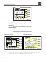
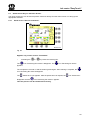
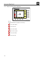
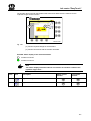
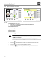
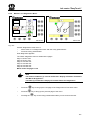
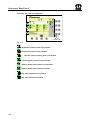
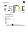
Info centre "EasyTouch" .....................................................................................................................92
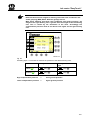
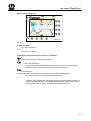
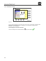
6.1.1 Overview ...................................................................................................................................... 92
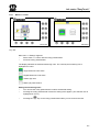
6.2
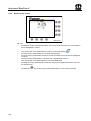
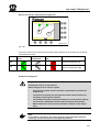
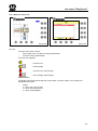
Information section .......................................................................................................................... 94
6.2.1
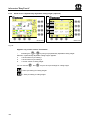
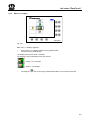
Status line (I) ................................................................................................................................ 95
6.2.2
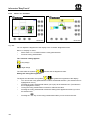
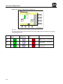
Motor data (II) information section ............................................................................................... 96
6.2.3
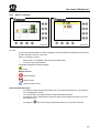
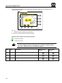
Information section of the travelling gear data (III) ...................................................................... 97
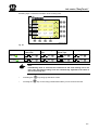
6.2.4
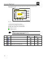
Information section of settings (IV and V) .................................................................................... 98
6.2.5
Drive data information section (VI) .............................................................................................. 98
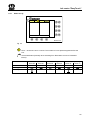
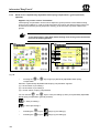
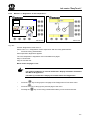
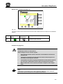
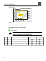
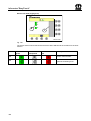
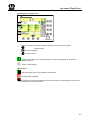
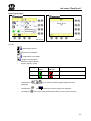
6.3
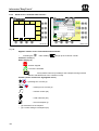
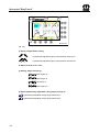
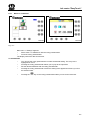
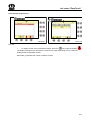
Quick Access Keys in the Basic Screen .......................................................................................... 99
6.3.1
Quick access "Reverse ventilation" ............................................................................................. 99
6.3.2
Quick access "Hydraulically adjustable cutting height" (optional) ............................................. 100
6.3.3
Quick access "Hydraulically adjustable lateral spring compensation" (ground pressure) (optional)
102
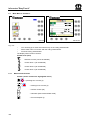
6.3.4
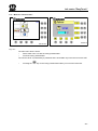
Quick access "Customer Data Counter" .................................................................................... 104
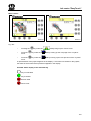
6.3.5
Changing a customer record (1) or creating a new one ............................................................ 105
6.3.5.1
Switching the counter on or off .......................................................................................... 106
6.3.5.2
Deleting the customer counter ........................................................................................... 107
6.3.5.3
Switching to General Counters (Machine Data Counters) ................................................ 107
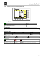
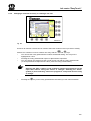
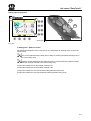
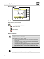
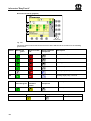
6.3.6
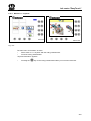
Quick access "Hydraulic axle suspension" ................................................................................ 108
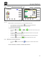
6.3.6.1
From the "Road travel" basic screen ................................................................................. 108
6.3.6.2
From the "Field mode" basic screen .................................................................................. 109
6.3.7
6.4
4
Multi-function lever (continued) ................................................................................................ 78
Quick access "Machine settings" ............................................................................................... 110
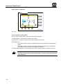
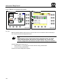
Menu Level .................................................................................................................................... 111
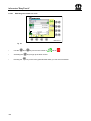
6.4.1
Short overview ........................................................................................................................... 111
6.4.2
Bringing up a Menu Level .......................................................................................................... 112
Table of Contents
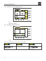
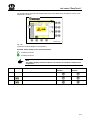
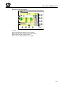
6.5
Menu 1-1 "Parameters" ................................................................................................................. 114
6.5.1
6.6
Entering parameters .................................................................................................................. 115
Menu 1-2 "Machine setting" ........................................................................................................... 116
6.6.1
Menu 1-3 "Units" ........................................................................................................................ 121
6.6.2
Menu 1-4 "Language" ................................................................................................................ 122
6.6.3
Menu 1-5 "Display" .................................................................................................................... 123
6.6.4
menu 1-5-1 "Contrast" ............................................................................................................... 124
6.6.5
Menu 1-5-2 Beeper .................................................................................................................... 125
6.6.6
Beeper limited by time ............................................................................................................... 126
6.6.7
Menu 1-6 "Date/time" ................................................................................................................. 127
6.7
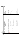
Main Menu 2 "Counters" ................................................................................................................ 128
6.7.1
Machine Data Counter ............................................................................................................... 128
6.7.1.1
6.7.2
6.8
Deleting the Machine Data Counters (Sets 1 to 3) ............................................................ 129
Switching to Customer DataCounters ....................................................................................... 129
Main Menu 3 "Maintenance" .......................................................................................................... 130
6.8.1
Menu 3-1 "Calibration of cutting height" .................................................................................... 131
6.8.2
Menu 3-4 „Manual mode“ .......................................................................................................... 134
6.8.3
Status display of general sensors (2) ........................................................................................ 136
6.9
Main Menu 4 Service ..................................................................................................................... 137
6.9.1
Menu 4-1 "Diagnostics" ............................................................................................................. 138
6.9.2
Display of Release Conditions Not Met for Diagnostics ............................................................ 139
6.9.3
Display of possible faults for diagnostics ................................................................................... 140
6.9.4
Menu 4-1-1 "Diagnostics of axle suspension" ........................................................................... 141
6.9.5
Menu 4-1-3 "Diagnostics of spring compensation" .................................................................... 144
6.9.6
Menu 4-1-4 "Diagnostics of cutting height" ................................................................................ 149
6.9.7
Menu 4-1-5 "Diagnostics of hydraulic auger hood" ................................................................... 157
6.9.8
Menu 4-1-6 "Sideshift diagnostics" ............................................................................................ 162
6.9.9
Menu 4-1-10 "Diagnostics Work" ............................................................................................... 167
6.9.10
Menu 4-1-11 "CAN bus" ........................................................................................................ 178
6.9.11
Menu 4-1-12 "Travelling gear" ............................................................................................... 179
6.9.12
Menu 4-1-13 "Electronics" ..................................................................................................... 188
6.9.13
Menu 4-1-14 "Diesel engine" ................................................................................................. 190
6.9.14
Menu 4-1-15 "Joystick" .......................................................................................................... 192
6.9.15
Menu 4-1-16 "Control unit console" ....................................................................................... 194
6.9.16
Menu 4-1-17 "Display" ........................................................................................................... 196
6.10
Menu 4-2 "Error list" ....................................................................................................................... 197
6.11
Menu 4-3 "Service level" ................................................................................................................ 201
6.12
Menu 4-4 "Information" .................................................................................................................. 202
6.12.1
Menu 4-4-1 "Joystick" ............................................................................................................ 203
6.12.2
Menu 4-4-3 "Machine" ........................................................................................................... 205
5
Table of Contents
6.13
7
6.13.1
Error message ....................................................................................................................... 207
6.13.2
Information message ............................................................................................................. 208
Commissioning ...................................................................................................................................209
7.1
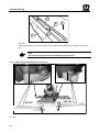
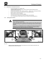
Fitting the guard cloths .................................................................................................................. 209
7.2
Folding Down Lateral Mowing Units .............................................................................................. 209
7.2.1
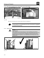
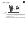
Description of Installation ........................................................................................................... 211
7.2.2
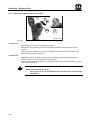
Guard cloths (CRI with upper roller drive) ................................................................................. 212
7.2.3
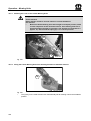
Adjusting the Warning Panel ..................................................................................................... 213
7.3
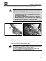
Installation of Cutter Blades ........................................................................................................... 213
8.1
Start-up ................................................................................................................................................214
Check before Start-up .................................................................................................................... 214
8.2
Daily checks ................................................................................................................................... 214
8
9
8.2.1
On the Basic Machine ................................................................................................................ 215
8.2.2
On the mowing units .................................................................................................................. 215
Driving and Transport ........................................................................................................................216
9.1
Transport / Road Travel ................................................................................................................. 216
9.2
Preparation for transport/road travel .............................................................................................. 217
9.2.1
Folding Up the Guards ............................................................................................................... 217
9.2.2
Move the front mowing unit to central position (with sideshift option) ....................................... 218
9.2.3
Check interlock .......................................................................................................................... 218
9.2.4
Disable the shut-off valve on the front outrigger. ....................................................................... 219
9.2.5
Release switch – road/field ........................................................................................................ 219
9.2.6
Release switch travelling gear ................................................................................................... 220
9.3
Starting the engine ......................................................................................................................... 221
9.3.1
Killing the engine ....................................................................................................................... 223
9.3.2
Starting with an Auxiliary Battery ............................................................................................... 223
9.4
Starting to Drive ............................................................................................................................. 223
9.4.1
Setting the acceleration behaviour ............................................................................................ 224
9.4.2
General on Driving ..................................................................................................................... 224
9.4.3
Preventing an overheating of the hydrostatic system ................................................................ 225
9.4.4
Driving forwards ......................................................................................................................... 226
9.4.5
Reversing ................................................................................................................................... 227
9.5
Cruise control ................................................................................................................................. 228
9.5.1
Storing the speed for the cruise control mode ........................................................................... 228
9.5.2
Activating cruise control ............................................................................................................. 229
9.5.3
Deactivating cruise control ......................................................................................................... 229
9.6
6
Menu 5 "Basic Screen" .................................................................................................................. 206
Stopping ......................................................................................................................................... 230
9.6.1
Stopping with the multi-function lever ........................................................................................ 230
9.6.2
Stopping with Foot Brakes ......................................................................................................... 231
Table of Contents
9.7
Parking brake ................................................................................................................................. 232
9.8
Switch off the engine ..................................................................................................................... 233
9.9
Switch off the machine ................................................................................................................... 233
9.10
Towing ........................................................................................................................................... 234
9.10.1
Releasing the holding brake manually ................................................................................... 234
10
Operation – Mowing Units .................................................................................................................235
10.1 Intended Use ................................................................................................................................. 235
10.2
Operation of Mowing Units ............................................................................................................ 236
10.3
Folding Down Lateral Mowing Units .............................................................................................. 237
10.3.1
Lowering the Lateral Mowing Units from Transport Position to Headland Position .............. 238
10.3.2
Lowering the Lateral Mowing Units from Headland Position to Working Position ................. 239
10.3.3
Lower the front mowing unit into working position ................................................................. 240
10.4
Headland Position .......................................................................................................................... 241
10.5
Mowing Unit Drive .......................................................................................................................... 242
10.5.1
Switching the Mowing Unit Drives On and Off ....................................................................... 243
10.5.2
Switching the Left Mowing Unit Drive On/Off ........................................................................ 243
10.5.3
Switching the Right Mowing Unit Drive On/Off ...................................................................... 244
10.5.4
Switching the Front Mowing Unit Drive On/Off ...................................................................... 245
10.5.5
Switching All Mowing Unit Drives On/Off ............................................................................... 246
10.6
Folding Up Lateral Mowing Units ................................................................................................... 247
10.6.1
Checking the Lock on the Lateral Mowing Units ................................................................... 248
10.6.2
Lifting the Lateral Mowing Units from working Position to Headland Position ...................... 248
10.6.3
Folding the Lateral Mowing Units from Headland Position to Transport Position ................. 249
10.6.4
Check interlock ...................................................................................................................... 250
10.7
Raising the Front Mowing Unit to Transport Position .................................................................... 250
10.8
Mowing........................................................................................................................................... 251
10.8.1
Moving the Guards into Working Position ............................................................................. 253
10.8.2
Semi-automatic mode ............................................................................................................ 254
10.8.3
Mowing with Individual Mowing Units .................................................................................... 254
10.8.4
Quick stop .............................................................................................................................. 255
10.8.5
Fast direction change (fast reversing) ................................................................................... 255
10.8.6
Switching Axle Separation On and Off .................................................................................. 256
11
Adjusting the mowing units ..............................................................................................................257
11.1 Special Safety Instructions ............................................................................................................ 257
11.2
Adjusting the cutting height............................................................................................................ 258
11.2.1
Front mowing unit .................................................................................................................. 258
11.2.2
Adjusting the Lifting Height .................................................................................................... 259
11.2.2.1
11.2.3
Front mowing unit .......................................................................................................... 259
Adjusting the cutting height .................................................................................................... 260
11.2.3.1
Lateral Mowing Unit ....................................................................................................... 260
7
Table of Contents
11.3
Adjusting the Compensation Springs ............................................................................................ 262
11.3.1
Front mowing unit .................................................................................................................. 263
11.3.2
Lateral Mowing Unit ............................................................................................................... 264
11.4
Adjusting the Tedder Speed .......................................................................................................... 265
11.4.1
Lateral Mowing Unit ............................................................................................................... 265
11.4.2
Front mowing unit (CV) .......................................................................................................... 266
11.5
Adjusting the conditioner plate ...................................................................................................... 267
11.6
Adjusting the roller conditioner (optional extra/Big M CRI) ............................................................ 268
11.6.1
Adjusting the roller distance ................................................................................................... 268
11.6.2
Adjusting the roller pressure .................................................................................................. 269
11.7
Setting of the Scraper on the Cross Conveyor (Optional) ............................................................. 270
11.8
Adjusting the swath width .............................................................................................................. 271
11.8.1
Front mowing unit .................................................................................................................. 271
11.8.2
Lateral Mowing Unit ............................................................................................................... 272
11.9
Adjusting the track control arm on the lateral mowing units .......................................................... 273
11.10
Deflector Plates.......................................................................................................................... 273
11.10.1
11.11
Front mowing unit .................................................................................................................. 273
Deactivating the axle suspension .............................................................................................. 274
12
Special Equipment – Mowing Units ..................................................................................................275
12.1 Converting the Tedder Deflector Plate to an Auger-Type Cross Conveyor .................................. 275
12.1.1
Removing the tedder deflector plate ...................................................................................... 276
12.1.2
Releasing the tension jacks ................................................................................................... 276
12.1.3
Removing the tedder deflector plate ...................................................................................... 277
12.1.4
Checking the Tines ................................................................................................................ 278
12.1.5
Removing the guard .............................................................................................................. 278
12.1.6
Installing the auger-type cross conveyor ............................................................................... 279
12.1.7
Locking the tension jacks ....................................................................................................... 280
12.2
8
Tensioning the V-belts ................................................................................................................... 280
12.2.1
Installing the guard ................................................................................................................ 281
12.2.2
Connecting the speed sensor ................................................................................................ 281
12.2.3
Removing the floor plates ...................................................................................................... 282
12.2.4
Relaying the Lubrication Lines ............................................................................................... 284
12.2.5
Installation Instructions – Bulge Bags for Big M 400 with BSS ............................................. 285
12.2.6
Switching on the auger monitoring mode .............................................................................. 286
12.2.7
Converting an Auger-Type Cross Conveyor to a "Tedder deflector plate unit" ..................... 288
12.3
Additional Equipment – Mulching Device ...................................................................................... 289
12.4
Removing Mowing Units ................................................................................................................ 290
12.4.1
Front mowing unit .................................................................................................................. 290
12.4.2
Removing of the compensation springs ................................................................................ 291
12.4.3
To remove the PTO shaft: ..................................................................................................... 292
Table of Contents
12.4.4
Removing the Weiste Triangle ............................................................................................... 294
12.4.5
Attaching the Front Mowing Unit ............................................................................................ 296
12.4.6
Removing the Side Mowing Unit ............................................................................................ 297
12.4.7
Attaching the Lateral Mowing Unit ......................................................................................... 304
12.4.8
The remainder of the installation is in reverse order to the removal procedure. ................... 306
13
Maintenance - Engine ........................................................................................................................307
13.1 Maintenance Table – Engine ......................................................................................................... 308
13.2
Contamination in the engine compartment .................................................................................... 309
13.3
Cleaning the Engine Compartment with Compressed Air ............................................................. 309
13.4
Engine oil level ............................................................................................................................... 310
13.4.1
13.5
Engine oil and filter replacement ........................................................................................... 310
Fuel filter/water separator .............................................................................................................. 311
13.5.1
Replacing the fuel filter .......................................................................................................... 311
13.5.2
Empty the water separator ..................................................................................................... 311
13.6
Replacing the fuel filter element .................................................................................................... 312
13.7
Fuel ................................................................................................................................................ 313
13.8
Tanks ............................................................................................................................................. 314
13.9
Venting the fuel system ................................................................................................................. 315
13.10
Engine coolant ........................................................................................................................... 315
13.11
Engine coolant - checks and controls ........................................................................................ 316
13.12
Air filter ....................................................................................................................................... 317
13.12.1
Safety cartridge ...................................................................................................................... 317
14
Maintenance – Mowing Units ............................................................................................................318
14.1 Special Safety Instructions ............................................................................................................ 318
14.1.1
Test run .................................................................................................................................. 319
14.2
Spare Parts .................................................................................................................................... 319
14.3
Maintenance Table – Mowing Units .............................................................................................. 320
14.4
Tool box ......................................................................................................................................... 321
14.5
Torques .......................................................................................................................................... 321
14.5.1
14.6
Filling Quantities and Lubrication Designations for Gearboxes ..................................................... 322
14.6.1
14.7
Lateral Mowing Unit ............................................................................................................... 323
Angular gearbox ............................................................................................................................ 324
14.8.1
14.9
Oil Level Check and Oil Change Intervals (Gearboxes) ........................................................ 322
Main gearbox ................................................................................................................................. 323
14.7.1
14.8
Deviating Torque ................................................................................................................... 322
Front Mowing Unit (CV+CRI) ................................................................................................. 324
Input gearbox ................................................................................................................................. 325
14.9.1
14.10
14.10.1
Front Mowing Unit (CV+CRI) ................................................................................................. 325
Speed gearbox........................................................................................................................... 326
Front mowing unit (CV) .......................................................................................................... 326
9
Table of Contents
14.11
Angular gearbox ........................................................................................................................ 327
14.11.1
CRI ......................................................................................................................................... 327
14.12
Gearbox for Top Roller Drive (optional) ..................................................................................... 328
14.13
Oil level check and oil change on the cutter bar ........................................................................ 329
14.13.1
Front mowing unit .................................................................................................................. 329
14.13.2
Aligning the Cutter Bar ........................................................................................................... 329
14.13.3
Checking the oil level ............................................................................................................. 330
14.13.4
Oil change .............................................................................................................................. 331
14.14
Oil level check and oil change on the cutter bar ........................................................................ 332
14.14.1
Lateral Mowing Unit ............................................................................................................... 332
14.14.2
Checking the oil level ............................................................................................................. 333
14.14.3
Oil change .............................................................................................................................. 334
14.15
Checking the Cutter Blades and Blade Holder .......................................................................... 335
14.15.1
Cutter Blades ......................................................................................................................... 335
14.15.2
Blade screw connection ......................................................................................................... 336
14.15.3
Blade Quick-Fit Device .......................................................................................................... 337
14.15.4
Periodical Inspection of the Leaf Springs .............................................................................. 338
14.15.5
Periodical Inspection of the Cutting Discs / Blade Drums ..................................................... 339
14.15.6
Abrasion Limit ........................................................................................................................ 340
14.16
Blade Changing on Cutting Discs .............................................................................................. 341
14.16.1
Blade Screw Connection ....................................................................................................... 342
14.16.2
Blade Quick-Fit Device .......................................................................................................... 343
14.17
Replacing the linings .................................................................................................................. 344
14.18
Rotary hub with shear protection ............................................................................................... 345
14.18.1
After Shearing Off .................................................................................................................. 347
15
Maintenance – Basic Machine ...........................................................................................................349
15.1 Brakes ............................................................................................................................................ 349
15.2
Hydraulic system ........................................................................................................................... 350
15.3
Maintenance - hydraulic system .................................................................................................... 353
15.3.1
System Description Operating and Brake Hydraulics............................................................ 353
15.3.2
Pumps .................................................................................................................................... 353
15.3.3
Main block .............................................................................................................................. 354
15.3.4
Over-pressure valves ............................................................................................................. 355
15.3.5
Adjustable Throttles ............................................................................................................... 355
15.4
Hydraulic oil ................................................................................................................................... 356
15.4.1
List of Mineral Oils for the Hydraulic System ......................................................................... 356
15.4.1.1
HEPG VG 46.................................................................................................................. 356
15.5
Hydraulic oil level ........................................................................................................................... 358
15.6
Replacing the hydraulic oil filter ..................................................................................................... 359
15.7
Transfer gearbox ........................................................................................................................... 360
10
Table of Contents
15.8
Air intake and distribution .............................................................................................................. 361
15.8.1
Fresh air fan ........................................................................................................................... 362
15.8.2
Circulation filter ...................................................................................................................... 363
15.9
Windscreen washer system ........................................................................................................... 364
15.10
Maintenance - air conditioning system and heating .................................................................. 365
15.11
Special Safety Instructions ........................................................................................................ 365
15.11.1
Air conditioning components .................................................................................................. 365
15.11.2
Refrigerant data sheet R 134a (excerpt) ............................................................................... 366
15.11.3
Technical data........................................................................................................................ 366
15.11.3.1
Refrigerant ..................................................................................................................... 367
15.11.4
Manometric switch ................................................................................................................. 367
15.11.5
Collector/drier......................................................................................................................... 368
15.11.6
Checking refrigerant condition and level ............................................................................... 369
15.12
Checking the capacitor .............................................................................................................. 370
15.13
Belt drives .................................................................................................................................. 371
15.13.1
Fan wheel drive...................................................................................................................... 372
15.13.2
Outrigger arms ....................................................................................................................... 373
15.13.3
Drive of mowing unit .............................................................................................................. 375
15.14
Tyres .......................................................................................................................................... 376
15.14.1
Checking and maintaining tyres............................................................................................. 377
15.14.2
Wheel mounting ..................................................................................................................... 378
15.14.3
Retightening the Attachment Bolts on the Outrigger ............................................................. 378
16
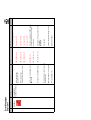
Maintenance – lubrication chart .......................................................................................................379
16.1 Lubricating the PTO shaft .............................................................................................................. 379
16.2
Lubricating the double joints on the main gearbox ........................................................................ 379
16.3
Lubrication Chart ........................................................................................................................... 380
17
Maintenance – electrical system .......................................................................................................381
17.1 Electrical equipment - technical data ............................................................................................. 381
17.2
Battery............................................................................................................................................ 382
17.2.1
Main battery switch ................................................................................................................ 383
17.2.2
Charging Batteries ................................................................................................................. 384
17.2.3
Quick charge .......................................................................................................................... 384
17.2.4
Cleaning the battery ............................................................................................................... 384
17.2.5
Check battery ......................................................................................................................... 385
17.2.6
Check acid level ..................................................................................................................... 385
17.2.7
Measuring Acid Density ......................................................................................................... 386
17.3
Fitting the batteries and connecting the poles correctly ................................................................ 387
17.4
Three-phase generator .................................................................................................................. 388
17.5
Starter ............................................................................................................................................ 389
17.6
Control units and fuses .................................................................................................................. 390
11
Table of Contents
17.6.1
MR2 engine control ................................................................................................................ 391
17.6.2
Cab relay PCB ....................................................................................................................... 391
17.6.2.1
17.7
Console Circuit Board .................................................................................................... 392
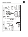
Console Circuit Board .................................................................................................................... 393
17.7.1
Krone Machine Controller circuit board (KMC1) .................................................................... 394
18
Maintenance – Central Lubrication...................................................................................................395
18.1 Lubricant fill .................................................................................................................................... 395
18.2
Fill coupling (fluid grease) .............................................................................................................. 395
18.3
Lubricant ........................................................................................................................................ 397
18.3.1
Grease types, NLGIClass 2 ................................................................................................... 398
18.4
Checking the fill level ..................................................................................................................... 399
18.5
Changing the times of the lubricating interval ................................................................................ 400
18.6
Troubleshooting ............................................................................................................................. 401
19
Placing in Storage ..............................................................................................................................402
19.1 At the End of the Harvest Season ................................................................................................. 402
19.2
Engine area.................................................................................................................................... 402
19.3
Before the Start of the New Season .............................................................................................. 403
19.4
Friction clutch -ByPy ...................................................................................................................... 404
19.4.1
Pos : 2 /BA/-----Seitenumbr uc h------ @ 0\mod_1196175311226_0.doc @ 4165
12
Venting the Friction Clutch on the PTO Shaft........................................................................ 404
Foreword
Pos : 3.1 /Ü bers chriften/Ü bersc hriften 1/U-Z/Vor wort @ 0\mod_1195627720123_78.doc @ 982
2
Foreword
Pos : 3.2 /Betriebsanl eitung/Vor wort/Sel bstfahrer/Ver ehrter Kunde BiG M 400 @ 0\mod_1195626522451_78.doc @ 925
Dear Customer
On buying the Self-Propelled High-Performance Mower-Conditioner Big M 400 you have
selected a quality product from KRONE.
We are grateful for the confidence you have invested in us in buying this machine.
It is important to read the operating instructions very carefully before you start operating the
machine so that the Self-Propelled High-Performance Mower-Conditioner Big M 400 may be
used to its maximum capacity.
The contents of this manual are laid out in such a way that you should be able to perform any
task by following the instructions step by step. It contains extensive notes and information about
maintenance, how to use the machine safely, secure working methods, special precautionary
measures and available accessories. It is essential, important and useful for the operational
safety, reliability and durability of the Self-Propelled High-Performance Mower-Conditioner Big
M 400, that these notes and information are adhered to.
Pos : 3.3 /Betriebsanl eitung/Vor wort/Sel bstfahrer/Weiter en Verlauf Big M 400 @ 0\mod_1195627075279_78.doc @ 963
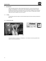
Note
Throughout the remainder of these operating instructions, the "Self-Propelled
High Performance Mowing Conditioner "Big M 400" will also be
referred to as the "machine / vehicle".
Pos : 3.4 /BA/Vor wort/Beachten Sie @ 0\mod_1195626904076_78.doc @ 944
Please note:
The operating instructions are part of your machine.
Only operate this machine after you have been trained to do so and according to these
instructions.
It is essential to observe the safety instructions!
It is also necessary to observe the relevant accident prevention regulations and other generally
recognised regulations concerning safety, occupational health and road traffic.
All information, illustrations and technical data in these operating instructions correspond to the
latest state at the time of publication.
We reserve the right to make design changes at any time and without notification of reasons.
Should you for any reason not be able to use these operating instructions either wholly or
partially, you can receive a replacement set of operating instructions for your machine by
quoting the number supplied overleaf.
We hope that you will be satisfied with your KRONE machine.
Maschinenfabrik Bernard Krone GmbH
Spelle
Pos : 4 /BA/-----Seitenumbr uc h------ @ 0\mod_1196175311226_0.doc @ 4165
13
Introduction
Pos : 5.1 /BA/Ei nleitung/Ei nleitung @ 0\mod_1195562498677_78.doc @ 416
3
Introduction
These operating instructions contain fundamental instructions. These must be observed in
operation and maintenance. For this reason, these operating instructions must be read by
operating personnel before commissioning and use, and must be available for easy reference.
Follow both the general safety instructions contained in the section on safety and the specific
safety instructions contained in the other sections.
Pos : 5.2 /BA/Ei nleitung/Gültigkeit/Selbs fahrer/BiG M 400 @ 0\mod_1195562702177_78.doc @ 435
3.1
Validity
The Operating Instructions apply to all Self-Propelled High Performance Mowing Conditioners
Big M 400.
Pos : 5.3 /Ü bers chriften/Ü bersc hriften 2/K- O/Kennzeic hnung @ 0\mod_1195564622099_78.doc @ 496
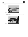
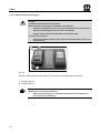
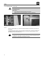
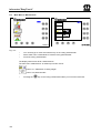
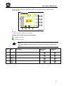
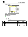
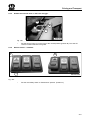
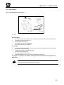
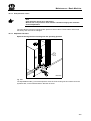
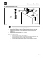
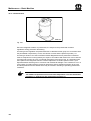
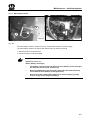
3.2
Identification Plate
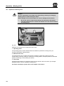
Pos : 5.4 /BA/Ei nleitung/Kennz eichnung/Big M 400 @ 0\mod_1195563094865_78.doc @ 476
Ma s c h in e n fa b r ik B e r n a r d K r o n e G m b H
Heinrich-Krone-Str. 10 D-48480 Spelle
1
Ma d e in
Germany
BM 400 0213
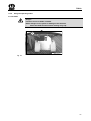
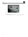
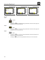
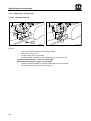
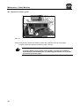
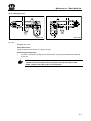
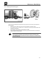
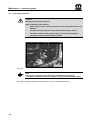
Fig. 1:
The machine data are located on a nameplate (1). It is located on the lower right side of the
machine on the front of the frame.
Pos : 5.5 /BA/-----Seitenumbr uc h------ @ 0\mod_1196175311226_0.doc @ 4165
14
Introduction
Pos : 5.6 /BA/Ei nleitung/Angaben für Anfrage und Bes tell ungen @ 0\mod_1195565119708_78.doc @ 515
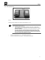
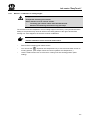
3.3
Information Required for Questions and Orders
Type
Year of manufacture
Vehicle ID number
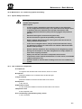
Note
The entire identification plate represents a legal document and should not be
altered or rendered illegible!
When asking questions concerning the machine or ordering spare parts, be sure to provide type
designation, vehicle ID number and the year of manufacture : To ensure that these data are
always available, we recommend that you enter them in the fields above.
Note
Authentic KRONE spare parts and accessories authorised by the
manufacturer help to ensure safety. The use of spare parts, accessories and
other devices which are not manufactured, tested or approved by KRONE will
result in the revoking of the liability for damages resulting thereof.
Pos : 5.7.1 /Ü bers chriften/Ü bersc hriften 2/A- E/Bes timmungsgemäß er Gebrauc h @ 0\mod_1196401545090_78.doc @ 7728
3.4
Intended Use
Pos : 5.7.2 /BA/Ei nleitung/Besti mmungsgemäß er Gebr auch/Selbs tfahr er/Besti mmungsgemäß er Gebrauch Big M 400 @ 0\mod_1195565634240_78.doc @ 536
The Big M II self-propelled high-performance mower-conditioner is a carrier vehicle for three
disc mowing units with a mowing conditioner. It is used to cut agricultural stalk and leaf crop.
Three individual mowing units allow the working width to be adapted. Integrated mowerconditioners accelerate the drying process of the mowed crop.
The self-propelled high performance mowing conditioner is intended exclusively for the
conventional use in agricultural or similar work (intended use).
Pos : 5.7.3 /BA/Ei nleitung/Besti mmungsgemäß er Gebr auch/Nicht bes timmungs gemäss @ 0\mod_1196401324340_78.doc @ 7690
Any use of the machine for other purposes is deemed not to be in accordance with intended
use. The manufacturer shall not be liable for any resulting damage; the user alone shall bear
the risk.
Operation in accordance with intended use also includes observing the operating, maintenance
and service instructions specified by the manufacturer.
Unauthorised modifications to the machine may affect the properties of the machine or disrupt
proper operation. For this reason, unauthorised modifications shall exclude any liability of the
manufacturer for consequential damage.
Pos : 5.8 /BA/-----Seitenumbr uc h------ @ 0\mod_1196175311226_0.doc @ 4165
15
Introduction
Pos : 5.9 /Ü bers chriften/Ü bersc hriften 2/K- O/M asc hinenübersic ht @ 0\mod_1195565731130_78.doc @ 555
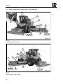
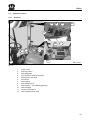
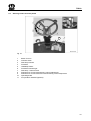
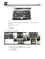
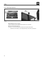
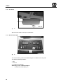
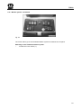
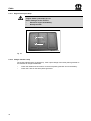
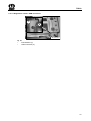
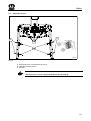
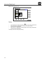
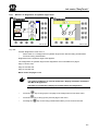
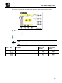
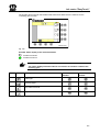
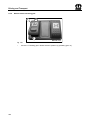
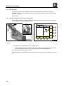
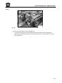
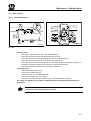
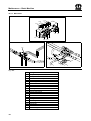
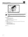
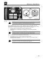
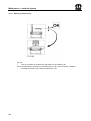
3.5
Machine overview
Pos : 5.10 /BA/Einl eitung/M asc hinenübersic ht/BiG M 400 @ 0\mod_1195565858365_78.doc @ 575
11
10
9
8
7
12
1
2
3
4
13
5
6
BM 400 0210
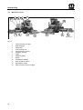
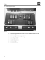
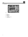
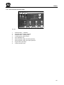
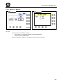
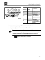
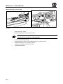
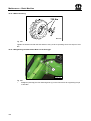
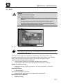
Fig. 2:
1
2
3
4
5
6
7
8
9
10
11
12
13
Pos : 5.11 /BA/-----Seitenumbruch------ @ 0\mod_1196175311226_0.doc @ 4165
16
Lateral mowing unit right
Right outrigger
Lifting gear
Front mowing unit
Lateral mowing unit left
Outrigger arm left
Cabin
Operating panel
Engine
Combination radiator
Work hydraulics valves
Main battery switch
Shut-off valve for front outrigger
Introduction
Pos : 5.12 /BA/Einl eitung/T ec hnnisc he Daten @ 0\mod_1195566374865_78.doc @ 594
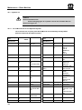
3.6
Technical data
All information, illustrations and technical data in these operating instructions correspond to the
latest state at the time of publication. We reserve the right to make design changes at any time
and without notification of reasons.
Pos : 5.13 /Betri ebs anleitung/Ei nleitung/Tec hnische D aten/Sel bstfahrer/Big M 400/Big M 400 F ahrz eug/M ähwer ke @ 0 \mod_1195566568365_78.doc @ 616
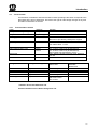
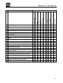
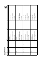
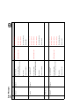
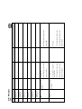
3.6.1
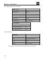
Technical Data / Vehicle
Power
Transport width/length/height
Weight
Weight distribution
Running gear
{KW/PS}
{mm}
{approx. kg.}
Steering
Tyres/air pressure
Tightening torque for wheel nuts
Hydrostatic travelling gear
Nm
Level I
Level II
Drive pump
260/354
3000 / 8180 / 4000
14000
about 9000 front / 5600 rear
4 wheels
Direct drive provided by radial piston engines
Rear axle steering
front 750/65 R26 – 1.8 bar
rear 580/70 R26 - 1.2 bar
630
0 to 19 km/h continuous (all-wheel drive)
0 to 40 km/h continuous (all-wheel drive)
Connectable axle separation in level 1
max. delivery capacity 425 l/min; max. pressure
430 bar
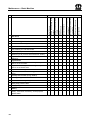
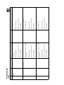
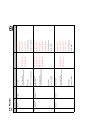
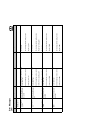
Filling Quantities
Filling quantities {I}
Filtered oils
Brand name
Diesel tank
Engine oil
Hydraulic oil
Coolant
Transfer gearbox
approx. 700
approx. 25.4
approx. 80
approx. approx. 6.0
see the "Engine" section
see the "Engine" section
Bio-degradable
lubricants
Brand name
HLP 46 HE 46 *)
see the "Engine" section
gearbox oil synthetic
DIN 51502 -PGLP
ISO VG 220
*) Caution: Do not mix with other oils.
Consult customer service before using other oils.
17
Introduction
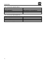
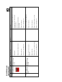
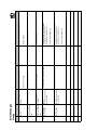
3.6.2
Technical Data / Big M II CV Mower
Working width total/individual {mm}
Transport width {mm}
Number of cutting discs
Number of blade drums
Conditioner system
Speed of the conditioner [rpm]
3.6.3
Technical Data / Mower BIG M II CRI
Working width total/individual {mm}
Transport width {mm}
Number of cutting discs
Number of blade drums
Conditioner system
Speed of the conditioner [rpm]
Pos : 6 /BA/-----Seitenumbr uc h------ @ 0\mod_1196175311226_0.doc @ 4165
18
9720/3140 front/3520 side
3000 mower
4/side mowing units - 5 front mowing units
4/side mowing units - 2 front mowing units
V-shaped prong
700 / 1000
9000 / 3140
3000 mower
5 / mower
2 / mower
rollers
760
Safety
Pos : 7.1 /Ü bers chriften/Ü bersc hriften 1/P-T /Sic her hei t @ 0\mod_1195566748646_78.doc @ 635
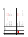
4
Safety
Pos : 7.2 /BA/Sic her heit/Sel bstfahrer/Sicherheit Ei nführ ung Big M 400 @ 0 \mod_1195566889349_78.doc @ 654
4.1
Introduction
The Big M 400 Self-Propelled High-Performance Mower-Conditioner is equipped with all the
necessary safety devices (protective devices). However, it is not possible to eliminate all
potential hazards on this machine as this would impair its full functional capability. Hazard
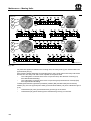
warnings are attached to the machine in the relevant areas to warn against any dangers. The
safety instructions are provided in the form of so-called warning pictograms. Important
information on the position of these safety signs and what they mean is given below!
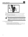
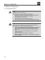
Pos : 7.3 /BA/Sic her heit/Bes chädigte oder unl es bar e Aufkleber @ 0\mod_1195567214115_78.doc @ 674
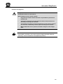
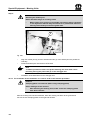
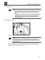
Danger!
Danger zone of the machine
Effect: Danger to life or serious injuries.
•
Immediately replace damaged or illegible adhesive labels.
•
Following repair work, always attach appropriate adhesive safety
stickers to all the replaced, modified or repaired components.
•
Never clean areas carrying an adhesive safety label using a highpressure cleaner.
•
Familiarise yourself with the statement of the warning pictograms. The
adjacent text and the selected location on the machine provide
information on the special danger spots on the machine.
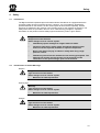
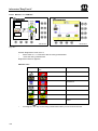
Pos : 7.4 /BA/Sic her heit/Kennzeic hnung der Gefahrenhi nweise @ 0\mod_1195567454333_78.doc @ 693
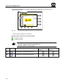
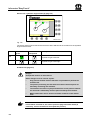
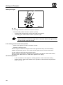
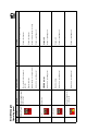
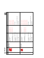
4.2
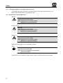
Identification of Hazard Warnings
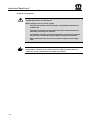
Danger!
Danger!
Type and source of the hazard
Effect: Danger to life or serious injuries.
•
Measures for hazard prevention
Warning sign
Warning!
Type and source of the hazard
Effect: Danger to life or serious injuries.
•
Measures for hazard prevention
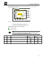
Caution!
Caution!
Type and source of the hazard
Effect: Danger to life or serious injuries.
•
Measures for hazard prevention
Pos : 7.5 /BA/-----Seitenumbr uc h------ @ 0\mod_1196175311226_0.doc @ 4165
19
Safety
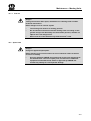
Pos : 7.6 /BA/Sic her heit/N achbestellung/ Anbringung Aufkleber @ 0\mod_1195637337107_78.doc @ 1079
4.2.1
Re-Ordering the Adhesive Safety and Information Labels
Note
Every adhesive safety and information label is assigned an order number and
can be ordered directly from the manufacturer or from an authorized dealer
(see Section "Contact").
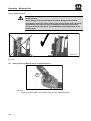
4.2.2
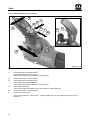
Affixing the Adhesive Safety and Information Labels
Note
Affixing an adhesive label
Effect: Adhesion of the label
•
The surface for affixing the adhesive label must be clean and free of
dirt, oil and grease.
Pos : 7.7 /Ü bers chriften/Ü bersc hriften 3/A- E/Ans prechpartner @ 0\mod_1195569394286_78.doc @ 839
4.2.3
Contact
Pos : 7.8 /Adr ess en/Adres se Mas chi nenfabri k KR ONE Spell e @ 0 \mod_1195568531083_78.doc @ 734
Maschinenfabrik Bernard Krone GmbH
Heinrich-Krone-Strasse 10
D-48480 Spelle (Germany)
Telephone: + 049 (0) 59 77/935-0 (Head Office)
Fax.: + 049 (0) 59 77/935-339 (Head Office)
Fax.: + 049 (0) 59 77/935-239 (Spare parts - domestic)
Fax.: + 049 (0) 59 77/935-359 (Spare parts - export)
Email: [email protected]
Pos : 7.9 /BA/-----Seitenumbr uc h------ @ 0\mod_1196175311226_0.doc @ 4165
20
Safety
Pos : 7.10 /BA/-----Seitenumbruch------ @ 0\mod_1196175311226_0.doc @ 4165
21
Safety
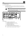
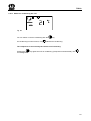
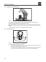
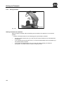
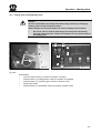
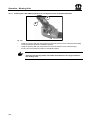
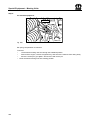
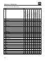
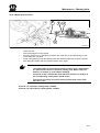
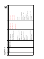
Pos : 7.11 /Übersc hriften/Übersc hriften 2/K-O/Lage der Sic herheits aufkleber an der Masc hi ne @ 0\mod_1195634967326_78.doc @ 1020
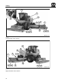
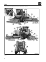
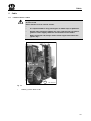
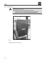
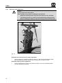
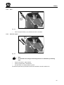
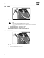
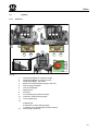
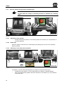
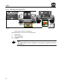
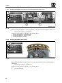
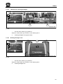
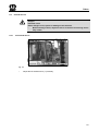
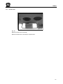
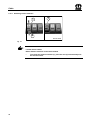
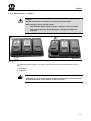
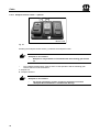
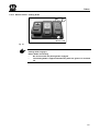
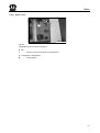
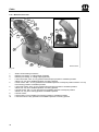
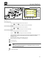
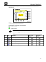
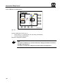
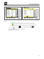
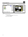
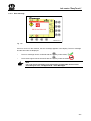
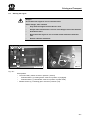
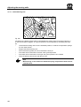
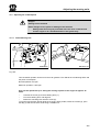
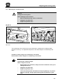
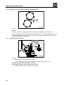
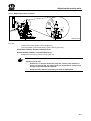
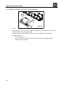
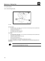
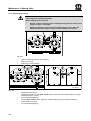
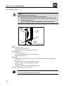
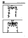
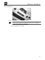
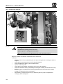
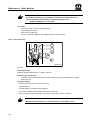
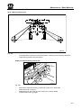
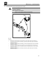
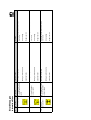
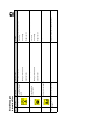
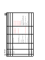
4.3
Position of the Adhesive Safety Stickers on the Machine
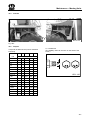
Pos : 7.12 /Betri ebs anleitung/Sic her hei t/Aufkl eber/Selbs tfahr er/Big M 400/Sic her hei tsaufkl eber Big M 400 @ 0 \mod_1195569734911_78.doc @ 861
3
1
8
6
7
3
4 7
9
2 4 5
2
2
2 4 5
BM 400 0178
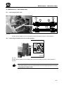
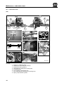
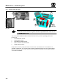
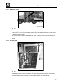
Fig. 3:
Left-hand side of the machine
11
8
2
3
6
7 4
10
2 4 5
2
Fig. 4:
Right-hand side of the machine
22
2 4 5
BM 400 0179
Safety
1)
Before starting the machine
read and observe the
operating instructions and
safety instructions.
2)
When the engine is in
operation, keep your distance.
Order No. 942,197-1 (8x)
Order No. 939 471-1 (1x)
3)
While parts are moving,
never reach into areas
where there is a risk of
being crushed.
4)
Do not touch any moving parts
of the machine.
Wait until they have come to a
complete stop.
Order no.
Order no. 942,196-1 (4x)
5)
Move guard into position
Order no. 939,572-0 (4x)
6)
Do not stand within the swivel range!
Order No. 939,469-1 (2x)
60
7)
Danger due to rotating
shaft.
8)
Order No. 939,520-1 (2x)
(with auger - option (4x))
939 520-1
9)
When making repairs (welding
work), always
Switch off the engine.
Disconnect the main battery
switch and remove the two
cable plugs from the PLD
control unit on the engine.
The accumulator is subject to gas and oil
pressure. Disassemble and repair in strict
accordance with the instructions in the
technical handbook.
Order No. 939,529-0 (2x)
10)
Caution: No short-circuit
produce!
Order No. 942,304-0 (1x)
50
Grund:
Schrift:
Kreuz:
gelb
schwarz
rot
942 304-0
50
Grund:
Schrift:
Kreuz:
gelb
schwarz
rot
23
Safety
3
1
8
6
7
3
4 7
9
2 4 5
2
2
2 4 5
BM 400 0178
Fig. 5:
Left-hand side of the machine
11
8
2
3
6
7 4
10
2 4 5
2
Fig. 6:
Right-hand side of the machine
24
2 4 5
BM 400 0179
Safety
11)
12)
Danger of falling!
Do not walk on ladder step.
Order No. 27 002 715 0 (1x)
Pos : 7.13 /Betri ebs anleitung/Sic her hei t/Aufkl eber/Selbs tfahr er/Big M 400/Sic her hei tsaufkl eber Big M 400_U SA @ 1 \mod_1201596794251_78.doc @ 53368
25
Safety
2 4
6
1 3
1
3
6
4
3 1
Fig. 7:
26
5
8
7
3
1
BM 400 0222
Safety
1)
2)
CAUTION
DANGER
Thrown objects or blade contact
can cause serious injury or death.
* Stay clear of machine while in
operation.
* Keep discharge chute and shields in
place.
* Replace worn or damaged protective
skirting.
To avoid serious injury or death
Read and understand operator
´s manual before
operating equipment.
Lower implement, stop tractor engine and
remove key before leaving operator
´s
platform.
Keep all shields and guards in place.
Keep hands feet and clothing away from
moving parts.
Keep riders off the machine.
Make certain every one is clear of the machine
before starting tractor engine and starting.
Do not allow unqualified operator to run
equipment.
Do not operate equipment in transport
position.
Never lubricatem, adjust, unclog or service
the equipment with tractor engine is running.
Wait for all movement to stop before
opening shield or servicing machine.
Never work underneath equipment without
securely supporting.
942 019-1
942 020 2 (4) Required
3)
942,019 1 (1) Required
4)
CAUTION
High pressure oil leaks can penetrate skin causing
serious injury and gangrene. (see operators manual &
consult a physican immediately.)
Do not use finger or other skin to check for leaks.
Lower load, release pressure, and be sure oil is cool
before loosening fitting.
942 050-0
939,495 1 (4) Required
5)
942,050 0 (3) Required
6)
WARNING
Close valve when
transporting or
servicing machine
942 032-2
942,032 2 (1) Required
942,018 1 (2) Required
7)
8)
949,229 0 (1) Required
949,228 0 (1) Required
Pos : 7.14 /BA/-----Seitenumbruch------ @ 0\mod_1196175311226_0.doc @ 4165
27
Safety
Pos : 7.15 /Übersc hriften/Übersc hriften 2/K-O/Lage der allgemeinen Hi nweis aufkleber an der Mas chi ne @ 0\mod_1195635067920_78.doc @ 1039
4.4
Position of the General Information Labels on the Machine
Pos : 7.16 /Betri ebs anleitung/Sic her hei t/Aufkl eber/Selbs tfahr er/Big M 400/Aufstellung Hinweis aufkleber Big M 400 Seite 1 @ 0 \mod_1195628093435_78.doc @ 1001
1
13
13
2
4
10
18
4
19
14
25
7
3
7
14 22
20
13
23 1
5
23
19 3 20 13
15
17
14
7
1
8
25
9
13
18 10
3 19
20
7
1
13
1
16
10
13
16
23
1
4
Fig. 8:
28
4
BM 400 0180
Safety
1)
2)
3)
4)
139-888
27,002,3920 (2x)
lg.=16000 mm beige
942,301 0 (1x)
lg.= 775 mm beige
5)
942,134 0 (1x)
10)
942 012-1
939 567 1 (x)
942,012 1 (4x)
6)
7)
8)
1.2 bar
942 3780 (4x) 1,2 bar
942,3770 (2x) 1.6 bar
939 451 1
939 145 1 (40 km/h) (3x)
939,218 1 (25 km/h) (3x)
924 634 0 (6x) side light
14)
15)
27 002 393 0 (2x)
lg.=1250 mm (green)
27 002 394 0 (4x)
lg.=550 mm (beige)
27 002 395 0 (3x)
lg.=440 mm (beige)
16)
80
Achtung!
Beide Unterlegkeile nur an
der Vorderachse verwenden.
Caution!
Use both wheel chocks for
the front axle only.
Attenzione!
N'utiliser les deux cales de
freinage que pour l'essieu avant
Let op!
Beide wielwiggen uitsluitend
onder de vooras gebruiken.
942,625 0 (1x)
942 626 0 (1)
13)
12)
40
1000
139 889-0
80
939,180 2 (1x)
11)
700
139-889
139 888-0
27 002 396 0 (2x)
H= 140 anthracite
27 002 397 0 (1x)
H= 68 anthracite
27 002 398 0 (3x)
H= 50 anthracite
27 024 920 0 (3x)
H= 68 beige
17)
233,154 0 (1x)
942 287-0
942,2400 (3x)
18)
942,287 0 (1x)
924,5690 (2x)
19)
19)
20)
+
Ø 17 mm
Ø 17,5 mm
942 729 0
80
min. 14 mm
255 499-1
min. 14 mm
80
255 498-1
+
80
22)
60
Bei Hangausgleich diese
Position verwenden.
Take this position by using
levelling mechanism.
255,4981 (3x)
with blade screw
connection
255,4991 (3x)
23)
25)
60
255 497-0
255,4970 (3x)
160
12 Volt - Netz
942 314 0
942 404 0
Qualität:
Fas Cal 895 glänzend
942,404
0 (1x)
Untergrund: blau
(ral 5010)
Schrift:
weiß
Bei Schweißarbeiten
ist der Hauptschalter
auszuschalten und
die Stecker der
Motorregelung PLD
am Motorblock
abzuziehen! 942 408-0
942,408 0 (1x)
942,314 0 (1x)
Pos : 7.17 /Betri ebs anleitung/Sic her hei t/Aufkl eber/Selbs tfahr er/Big M 400/Aufstellung Hinweis aufkleber Big M 400 Seite 2 USA @ 1\mod_1201599069189_78.doc @ 53429
29
Safety
2
4
1
3
BM 400 0181
Fig. 9:
30
Safety
1)
2)
60
3)
942 573 0 (1x)
942 570 -0
942 570 0 (1x)
942 571 -0
942 571 0 (1x)
5)
116
12V / 24 V
24 V
942 573 -0
4)
942 574 0 (1)
6)
942 481 (1)
942 427 0 (0)
Pos : 7.18 /BA/-----Seitenumbruch------ @ 0\mod_1196175311226_0.doc @ 4165
31
Safety
Pos : 7.19 /BA/Sicher heit/Ei nführ ungstext Kennz eic hnung von Hi nwei sen i n der Betriebsanl eitung @ 0 \mod_1195637804826_78.doc @ 1098
4.4.1
Identifying Symbols in the Operating Instructions
The safety instructions contained in this manual which could result in personal injury if not
followed are identified by the general danger sign:
Pos : 7.20 /BA/Sicher heit/Kennz eic hnung der Gefahr enhi nweis e @ 0\mod_1195567454333_78.doc @ 693
4.5
Identification of Hazard Warnings
Danger!
Danger!
Type and source of the hazard
Effect: Danger to life or serious injuries.
•
Measures for hazard prevention
Warning sign
Warning!
Type and source of the hazard
Effect: Danger to life or serious injuries.
•
Measures for hazard prevention
Caution!
Caution!
Type and source of the hazard
Effect: Danger to life or serious injuries.
•
Measures for hazard prevention
Pos : 7.21 /BA/Sicher heit/Allgemeine F unktions hinweis e @ 0\mod_1196869714452_78.doc @ 15185
General function instructions are indicated as follows:
Note!
Note
Type and source of the note
Effect: Economic advantage of the machine
•
Actions to be taken
Instructions which are attached to the machine need to be followed and kept fully legible.
Pos : 8 /BA/-----Seitenumbr uc h------ @ 0\mod_1196175311226_0.doc @ 4165
32
Cabin
Pos : 9.1 /Ü bers chriften/Ü bersc hriften 1/K- O/Kabine @ 0\mod_1195650476560_78.doc @ 1556
5
Cabin
Pos : 9.2 /BA/Kabi ne/Aufstiegsl eiter zur Fahrer kabi ne @ 0 \mod_1195647599076_78.doc @ 1499
5.1
Ladder to driver's cabin
Danger!
Access to cab
Effect: Danger to life or serious injuries.
•
•
It is impermissible to carry passengers on ladder steps or platforms.
•
Always make certain the ladders are clean. Take special care that no
grease or other slippery materials accumulates on the ladders.
•
When leaving the cab, always switch off the engine and remove the
ignition key.
Pos : 9.3 /BA/Kabi ne/Aufstiegsl eiter Big M 400 @ 0\mod_1195648056716_78.doc @ 1518
1
BM 400 0123
Fig. 10:
Pos : 9.4 /BA/-----Seitenumbr uc h------ @ 0\mod_1196175311226_0.doc @ 4165
•
Ladder (1) to the driver‟s cab
33
Cabin
Pos : 9.5 /Ü bers chriften/Ü bersc hriften 2/K- O/Kabinentür öffnen @ 0\mod_1195650425029_78.doc @ 1537
5.2
Opening the cabin door
Pos : 9.6 /BA/Kabi ne/T ür Öffnen von innen/außen @ 0\mod_1195651571638_78.doc @ 1633
1
BM 400 0182
Fig. 11:
•
From the outside: Use the door key to unlock the door lock (1); press in the button (1)
and open the door.
1
BM 400 0183
Fig. 12:
Pos : 9.7 /BA/-----Seitenumbr uc h------ @ 0\mod_1196175311226_0.doc @ 4165
34
•
From the inside: Lift the door opening lever (1) and open the door.
Cabin
Pos : 9.8 /Ü bers chriften/Ü bersc hriften 2/A- E/Bedienungs elemente @ 0\mod_1195651806826_78.doc @ 1652
5.3
Operators controls
Pos : 9.9 /Ü bers chriften/Ü bersc hriften 3/U-Z/Ü bersic ht @ 0\mod_1195651857513_78.doc @ 1671
5.3.1
Overview
Pos : 9.10 /BA/Kabi ne/Bedi enel emente Ü bersic ht Big M 400 @ 0\mod_1195651896076_78.doc @ 1690
12
5
10
11
9
6
3
4
7
1
8
2
BM 400 0001
Fig. 13:
Pos : 9.11 /BA/-----Seitenumbruch------ @ 0\mod_1196175311226_0.doc @ 4165
1
2
3
4
5
6
7
8
9
10
11
12
Driver‟s seat
Steering column
Operating brake
Foot switch for sideshift (optional)
Switch group roof panel
Info Centre
Switch panel
Multi-function lever
Switch group – air conditioning/heating
Interior lighting
Cooling compartment
ISO compartment for radio
35
Cabin
Pos : 9.12 /BA/Kabi ne/Luft- Komfort- Sitz @ 0\mod_1195652145685_78.doc @ 1709
5.4
Air comfort seat
Danger!
Brief distraction
Effect: Danger to life, injuries or damage to the machine.
•
The driver’s seat must only be adjusted when the machine is stopped.
10
1
2
8
3
9
4
5
6
7
BX500010
Fig. 14:
The air-cushioned comfort seat (1) can be individually adapted to the requirements of the driver.
Weight adjustment
In order to prevent health problems, the individual driver‟s weight adjustment should be checked
and adjusted prior to operation of the machine. The adjustment should be carried out whilst
sitting absolutely stationary.
•
Pull the lever (6) upwards briefly (position I).
Height adjustment
The height can be adjusted continuously by means of a hydraulic system. In order to prevent
damage, actuate the compressor for a maximum of 1 minute.
•
36
Pull the lever (6) upwards completely (position I) to move the driver‟s seat (1) up. Press
the lever (6) down completely (position II) to move the driver‟s seat (1) down. When the
upper or lower end position of the height adjustment mechanism is reached, the height
will be adjusted automatically in order to ensure a minimum spring travel.
Cabin
Horizontal suspension
The shock load in direction of travel through the driver‟s seat (1) is cushioned better by the
horizontal suspension.
•
Swing the lever (5) to the front - the horizontal suspension is active; swing the lever (5)
back – the horizontal suspension is switched off.
Longitudinal adjustment
•
Pull the locking lever (4) up, and push the driver‟s seat (1) forward or backward into the
requested position. Permit the locking lever (4) to snap into place; after locking, the
driver‟s seat must not be movable into any other position.
Seat angle adjustment
•
Pull the left key (3) up and at the same time set the angle of the sitting surface by
increasing or decreasing the pressure on the seat surface.
Seat depth adjustment
•
Pull the right key (2) up and at the same time bring the sitting surface into the required
position by pushing forward and backward.
Headrest
Set the headrest in such a way that the upper edges of the head and the headrest are on the
same height, if possible.
•
Adjust the height of the headrest (10) by pulling out and pressing down across the
noticeable snaps.
Lumbar support
•
The height as well as the intensity of the arching in the backrest can be adapted
individually by turning the hand wheel (9) to the left or right.
Adjustment of the backrest
•
Pull the locking lever (7) up to set the inclination of the backrest. Permit the locking lever
(7) to snap into place – after locking, the backrest must not move into a different position
any more.
37
Cabin
5.4.1
Setting the left armrest
8
11
BX100520
Fig. 15:
•
•
•
5.4.2
Tilt the armrest (8) up or down as requested.
Remove the cover cap (1) to adjust the height of the armrest.
Undo the hexagon nut; move the armrest into the requested position and tighten the
hexagon nut again. Press the cover cap (11) onto the hexagon nut again.
Right armrest
1
2
BX500011
Fig. 16:
The right armrest (1) and the multi-function lever are one unit.
Setting the right armrest
•
38
Undo the clamping screw (2); move the armrest (1) into the requested height and tighten
the clamping screw (2) again.
Cabin
5.4.3
Storage compartment for first-aid kit/operating instructions
1
2
BX100280
Fig. 17:
The storage compartment for the first-aid kit and the operating instructions (2) are located below
the front of the driver‟s seat (1).
Pos : 9.13 /BA/-----Seitenumbruch------ @ 0\mod_1196175311226_0.doc @ 4165
39
Cabin
Pos : 9.14 /BA/Kabi ne/Beifahr ersitz @ 0\mod_1195653672888_78.doc @ 1728
5.4.4
Passenger seat
Danger!
Hindrance to driver in the cab
Effect: Danger to life, injuries or damage to the machine.
•
Other than the driver, only one other person is permitted on the
passenger’s seat in the cab during work and transport travel.
1
BX100290
Fig. 18:
Folding down the passenger‟s seat (1).
Pos : 9.15 /BA/-----Seitenumbruch------ @ 0\mod_1196175311226_0.doc @ 4165
40
Cabin
Pos : 9.16 /BA/Kabi ne/Notaussti eg @ 0\mod_1195653995248_78.doc @ 1747
5.4.5
Emergency exit
b
a
1
2
1
c
d
1
2
3
BM 400 0171
Fig. 19:
In case of an emergency, the side window on the RH side in the direction of travel, next to the
driver's seat, can be opened as an exit door.
To do this:
Pos : 9.17 /BA/-----Seitenumbruch------ @ 0\mod_1196175311226_0.doc @ 4165
•
•
•
•
Swivel the lever (1) upward.
Press the lever (1) outwards and open the side window (2) slightly.
Pull the lever (1) from the pin (3).
Open the side window (2) completely
41
Cabin
Pos : 9.18 /BA/Kabi ne/Diagnos estec kdose – M otor @ 0\mod_1195654116482_78.doc @ 1766
5.4.6
Diagnosis socket - motor
1
BM 400 0173
Fig. 20:
The diagnostics socket (1) for the engine is located in the driver's cab on the bottom right in the
switch panel next to the driver's seat in the direction of travel.
Pos : 9.19 /BA/-----Seitenumbruch------ @ 0\mod_1196175311226_0.doc @ 4165
42
Cabin
Pos : 9.20 /BA/Kabi ne/Lenksäul e und F ußpedal e @ 0\mod_1195655010107_78.doc @ 1804
5.5
Steering column and foot pedals
3
5
1
6
2
4
8
10
11
BM 400 0016
Fig. 21:
1
2
3
4
5
6
7
8
9
10
11
Button for horn
Indicator switch
Pilot lamp indicator
Full beam
Headlamp flasher
Full beam indicator light
Pilot lamp – trailer function
Release lever for horizontal steering column adjustment
Release lever for horizontal and vertical steering column adjustment
Operating brake
Foot pedal for sideshift (optional)
43
Cabin
5.5.1
Steering column adjustment
Danger!
Loss of control over the machine
Effect: Danger to life, injuries or damage to the machine.
•
Adjust the steering column only when the machine is at a standstill.
•
The steering column (1) is held in vertical position by spring pressure.
Before actuating the pedal (2), hold the steering wheel with both hands.
1
3
2
BX100300
Fig. 22:
Horizontal and vertical steering column adjustment
•
Use the pedal (2) to release the steering column (1), and adjust to the desired position.
After the pedal (2) has been released, the steering column (1) will be locked.
Horizontal steering column adjustment
•
44
Loosen unlocking lever (3). Move the steering column (1) into the requested position.
Lock the release lever (3) again.
Cabin
5.5.2
Horn
1
BX100210
Fig. 23:
•
5.5.3
When the push-button (1) is pressed, the horn is sounded.
Indicator switch
1
2
BX100213
Fig. 24:
Note
In road traffic the change of travelling direction is indicated by a flashing
light.
•
Switch (1) forward – right indicator
•
Switch (1) backward – left indicator
•
Set the switch to neutral position by hand.
The indicator pilot lamp (2) will light up when the indicator has been switched on.
45
Cabin
5.5.4
Full beam
1
2
BX100212
Fig. 25:
Note
High beam only when dipped beam is turned on.
Turn off high beam when a vehicle is approaching from the opposite
direction.
•
Switching high beam on – press lever (1) down.
•
Switching high beam off – press lever (1) up.
When high beam is switched on, the blue pilot lamp (2) will be lit.
5.5.5
Headlamp flasher
BX200040
Fig. 26:
Pos : 9.21 /BA/-----Seitenumbruch------ @ 0\mod_1196175311226_0.doc @ 4165
46
•
Pull the headlamp flasher lever (1) up.
Cabin
Pos : 9.22 /BA/Kabi ne/Betriebs brems e betätigen @ 0\mod_1195656710279_78.doc @ 1823
5.5.6
Using the operating brake
In road traffic
Danger!
Function of service brake is limited.
Effect: Danger to life, injuries or damage to the machine.
•
Check the brake function before starting every trip.
1
BM 400 0017
Fig. 27:
Pos : 9.23 /BA/-----Seitenumbruch------ @ 0\mod_1196175311226_0.doc @ 4165
47
Cabin
Pos : 9.24.1 /Betri ebs anleitung/Kabi ne/Beleuc htung/Sc hal tergruppe D ac hkons ole @ 0\mod_1195658356216_78.doc @ 1861
5.6
Switch group roof panel
2
7
4
5
9
Fig. 28:
12
13
14
15
16
17
18
19
20
21
Pos : 9.24.2 /BA/-----Seitenumbruc h------ @ 0\mod_1196175311226_0.doc @ 4165
48
Working floodlights pointing down the side, and working floodlights pointing at the right
and left mowing units
Cab roof floodlights
Bottom working floodlight pointing to the front
Mirror adjustment (right outside mirror only)
Rear working floodlights
Side light/dipped beam
Allround lights (optional)
Hazard warning flasher
Windshield wipers
Windshield washer unit
Cabin
Pos : 9.24.3 /Übersc hriften/Übersc hriften 2/A-E/Beleuc htung @ 0\mod_1195658399935_78.doc @ 1881
5.7
Lighting
Pos : 9.24.4 /Übersc hriften/Übersc hriften 3/U-Z /Übersic ht @ 0\mod_1195651857513_78.doc @ 1671
5.7.1
Overview
Pos : 9.24.5 /Betri ebs anleitung/Kabi ne/Beleuc htung/Beleuchtung Ü bersic ht @ 0\mod_1195658459795_78.doc @ 1900
6
4
7
8
8
7
2
4
3
1
3
5
9
9
10
13
12
10
a
b
c
12
11
12
BM 400 0187
Fig. 29:
1
2
3
4
5
6
7
8
9
10
11
12
Pos : 9.24.6 /BA/-----Seitenumbruc h------ @ 0\mod_1196175311226_0.doc @ 4165
13
Working floodlights for mowing unit right
Working floodlights for mowing unit left
Working floodlights, side lower
Bottom working floodlight pointing to the front
Rear working floodlights
Cab roof floodlights
Dipped beam
Full beam
Front parking light (clearance lamp)
Indicators / hazard warning lights
Licence plate lamp
a) Brake light
b) Indicators / hazard warning lights
c) Tail light / rear parking light (clearance lamp)
Allround light (optional)
49
Cabin
Pos : 9.24.7 /Betri ebs anleitung/Kabi ne/Beleuc htung/Blinker, Warnblinkanlag e und Bremslic ht @ 0\mod_1195658983248_78.doc @ 1921
5.7.2
Indicator, hazard warning flasher and brake light
Note
In road traffic the change of travelling direction is indicated by a flashing
light.
12a
12b
10
10
BM 400 0184
Fig. 30:
5.7.2.1
Switching on the indicator
•
5.7.2.2
Actuate the direction indicator on the steering wheel; the indicators (10, 12b) will flash on
one side (right/left).
Brake light
When the ignition is switched on, the brake lights (12a) will light up as soon as the operating
brake is pressed.
5.7.2.3
Switching on the hazard warning flasher
1
12b
10
BM 400 0185
Fig. 31:
The switch (1) for the hazard warning flasher is located in roof panel switch group.
•
•
Pos : 9.24.8 /BA/-----Seitenumbruc h------ @ 0\mod_1196175311226_0.doc @ 4165
50
Actuate the rocker switch (1). The red pilot lamp in the switch (1) will start flashing.
When the hazard warning flasher has been switched on, all indicators (10, 12b) will flash
at the same time.
Cabin
Pos : 9.24.9 /Betri ebs anleitung/Kabi ne/Beleuc htung/St andlic ht / Abblendlic ht @ 0\mod_1195659623826_78.doc @ 1959
5.7.3
Side light/dipped beam
Fig. 32:
The rocker switch (1) for the parking light and the dipped beam is located in the roof panel
switch group.
The switch has three positions:
I - Off
II - Parking light
III – Dipped beam
5.7.3.1
Switching on the parking light
1
9
12c
BM 400 0188
Fig. 33:
•
Set the rocker switch (1) to position II:
The following lamps will light up when the parking light is switched on:
9
12c
Front parking light
Rear parking light
51
Cabin
5.7.3.2
Switching on the dipped beam
1
11
7
7
9
12c
BM 400 0189
Fig. 34:
•
Set the rocker switch (1) to position III.
When dipped beam is turned on, the following are lit:
7
9
11
12c
Dipped beam
Front parking light
Licence plate lamp
Tail light
Note
The dipped beam can be switched on only when the ignition has been
switched on.
Pos : 9.24.10 /BA/-----Seitenumbruc h------ @ 0\mod_1196175311226_0.doc @ 4165
52
Cabin
Pos : 9.24.11 /Betriebs anl eitung/Kabine/Beleuchtung/Arbeitssc heinwerfer @ 0\mod_1195660300091_78.doc @ 1985
5.7.4
Working floodlights
2
4
I
II
Fig. 35:
The rocker switch (1,2,3,4) for the working floodlights is located in the roof panel switch group.
Working floodlights pointing down the side, and working floodlights pointing at the right
and left mowing units
15
Cab roof floodlights
Bottom working floodlight pointing to the front
16
17
Rear working floodlights
It has 2 settings:
14
I
II
Off
On
Note
Always switch the working floodlights off during road travel!
53
Cabin
5.7.4.1
Working floodlights "down the side and at the right/left mowing units"
1
1
I
2
II
3
3
BM 400 0190
Fig. 36:
The two working floodlights (1,3) can be switched on only when the parking light is switched on.
•
Set the rocker switch (1) to position II:
When the rocker switch (1) is turned on, the following are lit:
1 Working floodlights for mowing unit right
2 Working floodlights for mowing unit left
3 Working floodlights, side lower
5.7.4.2
Working floodlights "Cab and rear"
2
I
II
6
BM 400 0191
Fig. 37:
The 7 working floodlights (6) on the cab roof can only be switched on when the parking light is
switched on.
•
Set the rocker switch (2) to position II:
When the rocker switch (2) is turned on, the following are lit:
6
54
Cab roof floodlights
Cabin
5.7.4.3
“Bottom front” working floodlight
3
I
II
4
4
BM 400 0192
Fig. 38:
•
Set the rocker switch (3) to position II:
When the rocker switch (3) is turned on, the following are lit:
4
5.7.4.4
Working floodlight front (right and left)
Working floodlight "rear"
4
5
I
II
BM 400 0193
Fig. 39:
•
Set the rocker switch (4) to position II:
When the rocker switch (4) is turned on, the following are lit:
5
Working floodlight rear
55
Cabin
5.7.5
Allround lights (optional)
13
1
BM 400 0125
Fig. 40:
Option depends on user’s country
In some countries the allround lights must be switched on in road traffic.
Switch on the allround lights (13)
The switch (1) for the allround lights is located in the roof panel switch group.
•
56
Actuate the rocker switch (1). The orange pilot lamp in the switch (1) will light up.
Cabin
5.7.6
Interior lighting
3
I
0
II
4
1
2
BM 400 0145
Fig. 41:
The interior lighting control (1) is located on the cab roof. It consists of a 3-level switch.
Overview:
I=
0=
II =
Continuous lighting
Lighting off
Delayed switch-off (after ignition stage II is turned off, interior lighting will stay on for the
amount of time set on time relay (2))
The time for switch-off delay can be adjusted with the time relay (2).
To do this:
•
•
Open the cover on the left next to the driver‟s seat.
Move switch (3) S1 and S2 to the desired position (see table).
S1
Off
On
On
Off
S2
Off
On
Off
On
(s)
110…900
14…110
2,5 14
0…2,5
Use a screwdriver to make fine adjustments to the speed potentiometer (4) of the time relay (2)
that controls the switch-off delay (amount of time) to match time intervals t(s).
57
Cabin
5.7.7
Spotlight
1
BMII-338
Fig. 42:
The spotlight (1) is on the cab roof.
Pos : 9.25 /BA/-----Seitenumbruch------ @ 0\mod_1196175311226_0.doc @ 4165
58
•
The spotlight can be turned on and off at any time by activating the switch built into it.
Cabin
Pos : 9.26.1 /Betri ebs anleitung/Kabi ne/Spieg el/Auß enspi egel @ 0\mod_1195710656280_78.doc @ 2005
5.8
Outside mirrors
Danger!
Impaired vision
Effect: Danger to life, injuries or damage to the machine.
•
5.8.1
Before starting to drive, adjust the mirror so that the rear driving area is
fully visible.
Left outside mirror
1
BM 400 0194
Fig. 43:
Pos : 9.26.2 /BA/-----Seitenumbruc h------ @ 0\mod_1196175311226_0.doc @ 4165
•
Adjust the left outside mirror (1) manually.
59
Cabin
Pos : 9.26.3 /Betri ebs anleitung/Kabi ne/Spieg el/Rechter Außens piegel und Anfahrspi egel @ 0 \mod_1195711324608_78.doc @ 2024
5.8.2
Right outside mirror and anti-collision mirror
2
1
3
BM 400 0146
Fig. 44:
The right outside mirror (1) and the anti-collision mirror (2) are electrically adjustable. The switch
(3) is located in the roof panel.
Setting the anti-collision mirror
Note
Set the anti-collision mirror in such a way that the ground area next to the
right front wheel can be checked prior to starting.
•
•
Pos : 9.26.4 /BA/-----Seitenumbruc h------ @ 0\mod_1196175311226_0.doc @ 4165
60
Turn the switch (3) to the left (arrow to the left).
Press the switch (3) up, down and to the side until the anti-collision mirror (2) is set
correctly.
Setting the right outside mirror
•
Turn the switch (3) to the right (arrow to the right).
•
Press the switch (3) up, down and to the side until the anti-collision mirror (1) is set
correctly.
Cabin
Pos : 9.26.5 /Betri ebs anleitung/Kabi ne/Spieg el/Innenspi egel @ 0\mod_1195711607577_78.doc @ 2043
5.9
Inside mirror
BMII-197
Fig. 45:
Adjust the inside mirror manually.
Adjust the inside mirror according to requirements.
Pos : 9.27 /BA/-----Seitenumbruch------ @ 0\mod_1196175311226_0.doc @ 4165
61
Cabin
Pos : 9.28 /BA/Kabi ne/Sonnenblende @ 0\mod_1195712512374_78.doc @ 2081
5.10 Sun blind
1
BMII-196
Fig. 46:
Adjust the sun blind according to requirements.
Pos : 9.29 /BA/Kabi ne/Frontsc heibenwis cher @ 0 \mod_1195712885140_78.doc @ 2100
5.11 Windshield wipers
Fig. 47:
The rocker switch (1) for the windshield wipers is located in the roof panel.
The switch has three positions:
I - Off
II - Interval
III - Continuous operation
Switching on the windshield wipers
•
Pos : 9.30 /BA/-----Seitenumbruch------ @ 0\mod_1196175311226_0.doc @ 4165
62
Actuate the rocker switch (1).
Cabin
Pos : 9.31 /BA/Kabi ne/Sc heibenwasc hanl age – Fr ontsc hei be @ 0\mod_1195713188280_78.doc @ 2119
5.12 Washer system - windshield
Fig. 48:
The rocker switch (1) for the windshield washer system is located in the roof panel.
Switching on the windshield washer system
Pos : 9.32 /BA/-----Seitenumbruch------ @ 0\mod_1196175311226_0.doc @ 4165
•
Actuate the rocker switch (1).
63
Cabin
Pos : 9.33.1 /Betri ebs anleitung/Kabi ne/Sc halterkons ole/Sc halter kons ol e @ 0 \mod_1195717034537_78.doc @ 2164
5.13 Switch panel
2
3
4
5
6
1
Fig. 49:
Pos : 9.33.2 /BA/-----Seitenumbruc h------ @ 0\mod_1196175311226_0.doc @ 4165
64
1
2
3
4
5
6
7
Panel switches
Pilot lamps
Ignition lock
Cigarette lighter
12 V socket
CAN diagnostics socket
USB connection
7
BM 400 0004
Cabin
Pos : 9.33.3 /Betri ebs anleitung/Kabi ne/Sc halterko ns ole/Kons olensc halter und Kontrollleuc hten @ 0\mod_1195717338990_78.doc @ 2183
5.14 Panel switches and pilot lamps
1 2
3
8
9
4
5
6
7
BM 400 0005
Fig. 50:
Pos : 9.33.4 /BA/-----Seitenumbruc h------ @ 0\mod_1196175311226_0.doc @ 4165
1
2
3
4
5
6
7
8
9
Release switch – road/field
Autopilot release switch (optional)
Release switch – holding brake
Travelling gear release switch
Axle separation key
Switch hydraulic auger hood left (optional)
Switch hydraulic auger hood right (optional)
Engine failure pilot lamp
Charge indicator lamp
65
Cabin
Pos : 9.33.5 /Betri ebs anleitung/Kabi ne/Sc halterkons ole/Betätigung Freigabeschalter @ 0 \mod_1195717535303_78.doc @ 2202
5.14.1 Actuating release switches
1
1
2
BX 400 0006
Fig. 51:
Note
Locked release switch
Effect: Release switches cannot be activated.
•
Pos : 9.33.6 /BA/-----Seitenumbruc h------ @ 0\mod_1196175311226_0.doc @ 4165
66
To actuate the release switches (1), push the lock (2) forward and press
the release switch.
Cabin
Pos : 9.33.7 /Übersc hriften/Übersc hriften 3/F-J/Freigabesc halter Straße/Fel d @ 0\mod_1196320452967_78.doc @ 6351
5.14.2 Release switch – road/field
Pos : 9.33.8 /BA/Sicherheit/Gefahr enhinweis e/Stellung Freigabeschalter bei Str aßenfahr t @ 0\mod_1196320338201_78.doc @ 6332
Danger!
Release switches for road travel not in position (I) "Road travel"
Effect: Danger to life or serious injuries.
•
The road/field release switch must be in position "I" for road travel.
•
This ensures that only the travelling gear, steering and brakes are
activated.
Pos : 9.33.9 /Betri ebs anleitung/Kabi ne/Sc halterkons ole/Fr eigabes chalter Straß e/F eld @ 0\mod_1195717693209_78.doc @ 2221
1
II
I
BM 400 0007
Fig. 52:
The road/field release switch (1) is used to switch from road travel to field operation and vice
versa.
I - Road travel
II - Field mode
Note
Depending on the position of the "Road/field" release switch, the "Road travel
or field mode" basic screen appears in the Info Centre.
Pos : 9.33.10 /BA/-----Seitenumbruc h------ @ 0\mod_1196175311226_0.doc @ 4165
67
Cabin
Pos : 9.33.11 /Betriebs anl eitung/Kabine/Sc hal ter konsol e/Freig abesc hal ter Autopilot / -opti onal @ 0\mod_1195717962350_78.doc @ 2240
5.14.3 Autopilot release switch / - optional
1
II
I
BM 400 0009
Fig. 53:
Actuating the autopilot release switch (1) releases the autopilot function.
Note
Autopilot is not released
•
Autopilot is only available in Field mode with the travelling gear turned
on
•
The road/field release switch must be active in field operation and the travelling gear
release switch must be switched on.
I - Autopilot off
II - Autopilot released
Note
Autopilot is not released
•
For further information, please consult the operating instruction
"Autopilot Brief Introduction" included with delivery
Pos : 9.33.12 /BA/-----Seitenumbruc h------ @ 0\mod_1196175311226_0.doc @ 4165
68
Cabin
Pos : 9.33.13 /Betriebs anl eitung/Kabine/Sc hal ter konsol e/Freig abesc hal ter F es tstellbrems e @ 0\mod_1195718259850_78.doc @ 2259
5.14.4 Release switch - holding brake
II
1
I
BM 400 0008
Fig. 54:
Note
Parking brake engaged
Effect: Brake overheating
•
Do not drive with the parking brake engaged.
•
The holding brake is applied automatically when the ignition is switched
off.
Pos : 9.33.14 /BA/-----Seitenumbruc h------ @ 0\mod_1196175311226_0.doc @ 4165
69
Cabin
Pos : 9.33.15 /Ü berschriften/Ü berschriften 3/F-J/Freigabes chalter F ahr antrieb @ 0\mod_1196319179092_78.doc @ 6293
5.14.5 Release switch travelling gear
Pos : 9.33.16 /BA/Sic herheit/Gefahrenhinweise/Ung ewolltes beweg en der Maschi ne @ 0 \mod_1196319463264_78.doc @ 6313
Danger!
Unintentional movement of the machine
Effect: Danger to life, injuries or damage to the machine.
•
No persons may be present in the direct hazardous area of the machine
when the travelling gear release switch is actuated!
•
Always remove the ignition key before leaving the cabin.
To turn off the machine:
•
Activate the parking brake switch; move the travelling gear switch (1) to
position off (I).
Pos : 9.33.17 /Betriebs anl eitung/Kabine/Sc hal ter konsol e/Freig abesc hal ter F ahrantrieb @ 0\mod_1195720600131_78.doc @ 2278
1
II
I
BM 400 0010
Fig. 55:
When the travelling gear release switch (1) is actuated, the travelling gear is released.
I - Travelling gear off
II - Travelling gear on
Note
Mower drives cannot be switched on.
•
When the travelling gear is switched off (position II), the mowing unit
drive cannot be switched on.
Pos : 9.33.18 /BA/-----Seitenumbruc h------ @ 0\mod_1196175311226_0.doc @ 4165
70
Cabin
Pos : 9.33.19 /Betriebs anl eitung/Kabine/Sc hal ter konsol e/T aste Achstrennung @ 0 \mod_1195722759115_78.doc @ 2297
5.14.6 Axle separation key
1
BM 400 0011
Fig. 56:
Actuating the axle separation key switches axle separation on or off.
Note
Axle separation does not turn on
•
Axle separation can only be activated in drive level 1 (field mode).
•
When activating the axle separation, the maximum top speed is 14 km/h
(instead of 19 km/h).
•
Pos : 9.33.20 /BA/-----Seitenumbruc h------ @ 0\mod_1196175311226_0.doc @ 4165
•
•
If the axle separation is switched when travelling faster than 14 km/h,
the electronics prevent the axle separation from being activated. Only
after the speed has been reduced to below 14 km/h, are the electronics,
the valves, and the axle separation activated.
Actuate axle separation key (1) – axle separation switched on
Actuate axle separation key (1) again – axle separation switched off
71
Cabin
Pos : 9.33.21 /Betriebs anl eitung/Kabine/Sc hal ter konsol e/Kontr ollleuc hte M otorstörung /La dekontr ollleuchte @ 0\mod_1195723288303_78.doc @ 2317
5.14.7 Engine failure pilot lamp
Caution!
"Engine failure" pilot lamp (1) is lit
Effect: Damages to the machine
•
Switch off engine immediately.
•
Rectify the fault.
1
2
BM 400 0012
Fig. 57:
5.14.8 Charge indicator lamp
The charge indicator light (2) will light up, if the output voltage of the three-phase generator is
not sufficient to charge the batteries.
Pos : 9.33.22 /BA/-----Seitenumbruc h------ @ 0\mod_1196175311226_0.doc @ 4165
72
•
•
Check the cables and connections on the three-phase generator and on the battery.
Check the V-belt on the three-phase generator.
Cabin
Pos : 9.33.23 /Betriebs anl eitung /Kabine/Sc hal ter konsol e/Z ündsc hloss @ 0\mod_1195724199693_78.doc @ 2336
5.14.9 Ignition lock
1
BM 400 0013
Fig. 58:
The ignition lock (1) has four positions:
0 - Off
I-
Electric circuit for electronics is switched on
II The ignition is switched on
III -
Start position
Pos : 9.33.24 /BA/-----Seitenumbruc h------ @ 0\mod_1196175311226_0.doc @ 4165
73
Cabin
Pos : 9.33.25 /Betriebs anl eitung/Kabine/Sc hal ter konsol e/Zigar ettenanz ünder / 12 V Stec kdos e @ 0\mod_1195725058068_78.doc @ 2355
5.14.10 Cigarette lighter / 12-V socket
Caution!
Hot cigarette lighter!
Effect: Burns
•
Only hold the hot cigarette lighter by the handle.
•
Never hold onto the cigarette lighter (1) when it is pushed in.
1
2
BM 400 0014
Fig. 59:
Press the cigarette lighter (1) in; when the required temperature is reached the insert will come
out by itself.
The socket (2) can be used to connect other power consumers with 12 volts and a maximum of
10 amperes. When the engine has been switched off, the battery will be discharged. Use the
specified plug to connect accessory units.
Note
An additional 12-V socket is located in the driver’s cab on the bottom left next
to the driver’s seat facing in the direction of travel.
Pos : 9.33.26 /BA/-----Seitenumbruc h------ @ 0\mod_1196175311226_0.doc @ 4165
74
Cabin
Pos : 9.33.27 /Betriebs anl eitung/Kabine/Sc hal ter konsol e/Diag noses tec kdos e / USB-Ansc hluss @ 0\mod_1195725557209_78.doc @ 2374
5.14.11 Diagnostics socket / USB connection
1
2
BM 400 0015
Fig. 60:
Pos : 9.34 /BA/-----Seitenumbruch------ @ 0\mod_1196175311226_0.doc @ 4165
•
•
CAN interface (1)
USB connection (2)
75
Cabin
Pos : 9.35.1 /Betri ebs anleitung/Kabi ne/Multi funkti onshebel/M ultifunktions hebel @ 0 \mod_1195727312881_78.doc @ 2414
5.15 Multi-function lever
3
1
6
7
10
11
2
23 15
4
5
22
8
13 14
9
17
18
16
12
19
20
21
BM 400 0003
Fig. 61:
1
2
3
4
5
6
7
8
9
10
76
Switch off all mowing unit drives
Retrieve pre-setting "I" cutting height (optional)
Retrieve pre-setting "II" cutting height (optional)
Lower left mower: with "12" key pressed from transport position to headland position
without "12" key from headland position to working position
Lift left mower: with "12" key pressed from headland position to transport position without "12" key
from working position to headland position
Lower right mower: with "12" key pressed from transport position to headland position
without "12" key from headland position to working position
Lift right mower: with "12" key pressed from headland position to transport position
without "12" key from working position to headland position
Lift front mower
Lift all mowers: Only possible from working position to headland position
Lower all mowers: Only possible from headland position to working position
Cabin
11
12
13
14
15
16
17
18
19
20
21
22
23
Lower front mower
Additional function for keys "4 to 7"
Switching between semi-automatic and automatic
LED lit semi-automatic active
LED not lit automatic active
Actuation key for travelling gear
Selector switch – acceleration ramp
Additional function: Mowing units - release
Activation key for Autopilot (optional)
In Field mode only: Increase engine speed inching until nominal speed is reached
In Field mode only: Switch from nominal speed to idle speed and vice versa
In Field mode only: Reduce engine speed inching until idle speed
Free
Cross switch lever
Pos : 9.35.2 /BA/-----Seitenumbruc h------ @ 0\mod_1196175311226_0.doc @ 4165
77
Cabin
Pos : 9.35.3 /Betri ebs anleitung/Kabi ne/Multi funkti onshebel/M ultifunktions hebel (For tsetzung) @ 0 \mod_1195727857584_78.doc @ 2433
5.15.1 Multi-function lever (continued)
E
F
G
D
H
J
K
L
M
23
15
17
16
A
B
C
BM 400 0133
Fig. 62:
A
BC-
DEF-
78
Acceleration (during forward travel)
Deceleration (during reverse travel)
Start travelling gear with activation key pressed (15)
Multi-function lever – central position
Acceleration (during reverse travel)
Deceleration (during forward travel)
Start travelling gear with activation key pressed (15)
Deceleration to 0 km/h
Fast reversing with the activation key (15) pressed (in Field mode only)
Multi-function lever – central position
Switch on cruise control
Save current speed for cruise control – press activation key (15) and rotate multi-function lever in
direction F
Cabin
GHJKLM-
without key (17) pressed, switch off left mower drive
with key (17) pressed, switch on left mower drive
Central position
without key (17) pressed, switch off right mower drive
with key (17) pressed, switch on right mower drive
without key (17) pressed, switch off front mower drive
with key (17) pressed, switch on front mower drive
Central position
without key (17) pressed, switch off all mower drives
with key (17) pressed, switch on all mower drives
Pos : 9.36 /BA/-----Seitenumbruch------ @ 0\mod_1196175311226_0.doc @ 4165
79
Cabin
Pos : 9.37.1 /Betri ebs anleitung/Kabi ne/Kli maanlag e/H eizung/Kli matroni k / H eizung Übersic ht @ 0\mod_1195728661475_78.doc @ 2453
5.16 Klimatronik / heating
5.16.1 Control and display elements
The Klimatronik is a control unit for air conditioning and heating systems in modern vehicle
cabs. The driver‟s work is made easier through clear, intuitive control of all tasks and optimum
climate control in the driver‟s cab.
Note
If the electrical power supply to the control unit is interrupted, the control unit
automatically performs a self test after power is restored. After the self test is
complete, the last setting to be saved appears.
Fig. 63:
Key function key
24
25
26
27
28
29
30
31
80
Key to switch air conditioning on and off
Key to adjust the desired cab temperature upward.
Alternative: Manual settings "Up"
Key to adjust the desired cab temperature downward.
Alternative: Manual settings "Down"
Key to switch the controller on and off
Key to switch the evaporator fan speed Manual / Automatic
Key to switch REHEAT mode on and off (demoisturising the cab air)
Covered key to switch the temperature display to ° Fahrenheit
Cabin
LCD function of LCD display
Pos : 9.37.2 /BA/-----Seitenumbruc h------ @ 0\mod_1196175311226_0.doc @ 4165
32
33
34
35
36
37
38
39
Icon indicates REHEAT mode
Icon indicates air conditioning
Icon indicates fully automatic mode is turned on
Bar indicates fan speed in manual mode
Icon indicates manual fan mode
4-place seven segment display shows setpoint value or error code
Icon indicates unit of measure for temperature (°)
Indicates the icon for vehicle cab
81
Cabin
Pos : 9.37.3 /Betri ebs anleitung/Kabi ne/Kli maanlag e/H eizung/Anlag e einsc halten @ 0\mod_1195729216365_78.doc @ 2491
5.16.2 Operation
5.16.3 Switching on the System
Fig. 64:
Press the
key
Note
After the system is switched on, the control unit performs a self test and the
software version is displayed for about 5 seconds, for example:
Then the operating hours of the air conditioning system are displayed for 5 seconds (for
example 6 operating hours).
Then the last saved setting appears in the display.
Pos : 9.37.4 /Betri ebs anleitung/Kabi ne/Kli maanlag e/H eizung/Ei nstellen der gewünsc hten Kabinentemperatur @ 0\mod_1195729761475_78. doc @ 2510
5.16.4 Setting the Desired Cab Temperature
Fig. 65:
The set cab temperature is shown in °C, for example 26°C. The control unit is in Automatic
mode.
To lower the desired cab temperature to 21°C, for example, press the
value appears in the display. (press key 5 x)
Pos : 9.37.5 /BA/-----Seitenumbruc h------ @ 0\mod_1196175311226_0.doc @ 4165
82
key until the desired
Cabin
Pos : 9.37.6 /Betri ebs anleitung/Kabi ne/Kli maanlag e/H eizung/Kli mabetrieb Ein- / Ausschalten @ 0\mod_1195730018068_78.doc @ 2529
5.16.5 Switch air conditioning On / Off
Fig. 66:
You can switch on the air conditioning with the
Air conditioning is now turned on; icon
key.
indicates air conditioning.
The compressor is turned on by the control unit if necessary.
Pressing the
icon disappears.
key again turns off air conditioning (compressor is deactivated). The
Pos : 9.37.7 /BA/-----Seitenumbruc h------ @ 0\mod_1196175311226_0.doc @ 4165
83
Cabin
Pos : 9.37.8 /Betri ebs anleitung/Kabi ne/Kli maanlag e/H eizung/REH EAT - Betri eb Ei n- / Aussc hal ten @ 0\mod_1195733396084_78.doc @ 2548
5.16.6 Switch REHEAT mode On / Off
Fig. 67:
REHEAT mode = (demoisturising the cab air)
Switch on REHEAT mode with the
key.
The display appears like this:
REHEAT mode is now turned on. The
icon indicates REHEAT mode.
Note
The compressor is permanently turned on. The evaporator fan speed is raised
to 100%. If necessary, the control unit turns the heating on to keep room
temperature at the setpoint value.
REHEAT mode is automatically limited to 10 minutes.
Pressing the
The
Pos : 9.37.9 /BA/-----Seitenumbruc h------ @ 0\mod_1196175311226_0.doc @ 4165
84
key again turns off REHEAT mode.
icon no longer appears.
Cabin
Pos : 9.37.10 /Betriebs anl eitung/Kabine/Kli maanl age/Heiz ung/M anuelles Ei nstellen der Ver dampferlüfterdr ehz ahl @ 0\mod_1195733653506_78.doc @ 2567
5.16.7 Manual setting of evaporator fan speed
Fig. 68:
Switch on manual evaporator fan speed with the
key.
The manual setting for fan speed is now active. The currently set fan speed appears in bar
(full bar display = 100%). The AUTO icon no longer appears.
display
Fan
flashes for 5 seconds. During this time the fan speed can be increased with the
key or lowered with the
key in increments of 10%.
Note
The lowest fan speed that can be set is 30% (three bars are displayed).
Pressing the
and
key twice reactivates AUTO mode. The Auto icon appears ; the
icons are no longer displayed.
Pos : 9.37.11 /BA/-----Seitenumbruc h------ @ 0\mod_1196175311226_0.doc @ 4165
85
Cabin
Pos : 9.37.12 /Betriebs anl eitung/Kabine/Kli maanl age/Heiz ung/U mschalten der T emperatur anzeige in ° F ahr enheit @ 0\mod_1195734049209_78.doc @ 2586
5.16.8 Switching the Temperature Display to ° Fahrenheit
8
Fig. 69:
The current set-point temperature is shown in ° Celsius.
Press and hold the covered key (8) and press the
Fahrenheit.
key as well. The display switches to °
The current set-point temperature is shown in ° Fahrenheit.
Pressing the (8) key and
Pos : 9.37.13 /BA/-----Seitenumbruc h------ @ 0\mod_1196175311226_0.doc @ 4165
86
key again switches the display back to ° Celsius.
Cabin
Pos : 9.37.14 /Betriebs anl eitung/Kabine/Kli maanl age/Heiz ung/Anzeig e von Störungen i m Dis pl ay @ 0\mod_1195734281959_78.doc @ 2605
5.16.9 Showing Faults in the Display
Error code (F0)´
Fig. 70:
Error in room temperature sensor is indicated by flashing indicator (F0).
Note
The control unit has recorded an error in the room temperature sensor.
Controller is no longer ready for operation.
Cause of sensor fault:
Short circuit or interruption in sensor line, plug connection on the sensor or control unit ,
temperature sensor defective. The controller will not be ready for operation again until the error
is eliminated. Then the sensor fault no longer appears.
Note
If a sensor fault occurs, the controller continues working with the setting that
was valid before the fault was recorded.
87
Cabin
Error code (FI)
Fig. 71:
Error in blow-out temperature sensor is indicated by flashing indicator (F1).
Note
The control unit has recorded an error in the blow-out temperature sensor.
The
control is no longer ready for operation.
Cause of sensor fault:
Short circuit or interruption in sensor line, plug connection on the sensor or control unit ,
temperature sensor defective. The controller will not be ready for operation again until the error
is eliminated. Then the sensor fault no longer appears.
Note
If a sensor fault occurs, the controller continues working with the setting that
was valid before the fault was recorded.
Pos : 9.38 /BA/-----Seitenumbruch------ @ 0\mod_1196175311226_0.doc @ 4165
88
Cabin
Pos : 9.39 /BA/Kabi ne/Verstellbare Lüftdüsen @ 0\mod_1195735466631_78.doc @ 2625
5.17 Adjustable air jets
C
C
A/B
A/B
BMII-200
Fig. 72:
A Knurled wheel to control the amount of air
B Adjustment of the louvers
C Air slots
Note
Set the louvers in such a way that the panes do not mist up.
Pos : 9.40 /BA/-----Seitenumbruch------ @ 0\mod_1196175311226_0.doc @ 4165
89
Cabin
Pos : 9.41 /BA/Kabi ne/Radioeinbau @ 0\mod_1195735722428_78.doc @ 2644
5.18 Radio
1
BM 400 0215
Fig. 73:
1
ISO compartment for radio
Note
Telephones and radio equipment not connected to the outside antenna may
lead to functional troubles in the vehicle's electronic system, thus
jeopardising the operational safety of the vehicle.
Pos : 10 /BA/-----Sei tenumbruch------ @ 0\mod_1196175311226_0.doc @ 4165
90
Cabin
Pos : 11 /BA/-----Sei tenumbruch------ @ 0\mod_1196175311226_0.doc @ 4165
91
Info centre "EasyTouch"
Pos : 12.1 /Übersc hriften/Übersc hriften 1/F-J/Info-Center „Eas yT ouch“ @ 0\mod_1195737815318_78.doc @ 2663
6
Info centre "EasyTouch"
Pos : 12.2 /Übersc hriften/Übersc hriften 3/U-Z/Übersic ht @ 0\mod_1195651857513_78.doc @ 1671
6.1.1
Overview
Pos : 12.3 /BA/Info-C enter/Big M 400/Info-Center Eas y T ouch Übersic ht @ 0\mod_1195737934803_78.doc @ 2682
I
II
III
IV
V
BM 400 0099
Fig. 74:
Pos : 12.4 /BA/-----Seitenumbruch------ @ 0\mod_1196175311226_0.doc @ 4165
92
•
I = Display
•
II = Keys
•
•
III = Keys
to D D (A - D)
IV = Rotary potentiometer
•
V = Menu key
1
to 8
8
(1 - 8)
Info centre "EasyTouch"
Pos : 12.5 /BA/Info-C enter/Big M 400/Allgemei ne Besc hrei bung der T asten_Dr ehpoti_M enütas te @ 0\mod_1195738501881_78.doc @ 2701
2
IV
V
B
C
5
6
7
8
1
BM 400 0101
D
BM 400 0100
Fig. 75:
The Info Centre informs you about the current actions and the current operating condition of the
machine. You can use the Info Centre to make settings for the machine and start or stop
actions. Its main components are:
Keys 1-8
Keys 1-8 are used to activate the softkeys located in the right column (IV). For the assignment
of the keys, see the illustration. If there is no softkey next to the key, it has no function.
Keys A-D
The keys A-D are used to activate the softkeys located in the line just above them (V). For the
assignment of the keys, see the illustration. If there is no softkey above the key it has no
function.
Rotary potentiometer (1)
The rotary potentiometer has two functions:
2
The rotary potentiometer can be turned to change settings and to select the desired
menu in the menu level.
3
Pressing the rotary potentiometer activates and saves the settings.
Menu key (2)
You can use the key with the rotary potentiometer to call or close the menu level or to go to the
preceding menu level. Holding the key down slightly longer takes you back to the basic screen.
1
Pos : 12.6 /BA/-----Seitenumbruch------ @ 0\mod_1196175311226_0.doc @ 4165
93
Info centre "EasyTouch"
Pos : 12.7.1 /BA/Info-C enter/Big M 400/Bes chr eibung Infober eic he/Dis pl ay Bes chr eibung @ 0\mod_1195739127068_78.doc @ 2740
I
II
IV
III
VI
V
B
C
5
6
7
8
D
BM 400 0114
Fig. 76:
Display (screen display)
The display is divided up into the following sections:
Status line (I):
•
Time, number of errors, status display of mowing units
Information section:
•
•
•
•
Pos : 12.7.2 /BA/Info-C enter/Big M 400/Bes chr eibung Infober eic he/Infor mati ons bereic h @ 0 \mod_1195739494271_78.doc @ 2759
6.2
Engine information (II)
Travelling gear information (III)
Settings (IV and V)
Drive information (VI) (only in Field mode basic screen)
Information section
Basic screen - road travel
15:36
Field mode basic screen
1
0
UPM
km/h
840 0.0
0
20
40
60
80
4
100
100
N
75
5
6
5
6
7
8
7
8
50
25
0
70°C
B
C
D
B
BM 400 0104
C
D
BM 400 0103
Fig. 77:
After the ignition is switched on, depending on the position of the "Road / field" release switch,
the basic screen "Road travel" or "Field mode" appears in the display.
Pos : 12.7.3 /BA/-----Seitenumbruc h------ @ 0\mod_1196175311226_0.doc @ 4165
94
Info centre "EasyTouch"
Pos : 12.7.4 /BA/Info-C enter/Big M 400/Bes chr eibung Infober eic he/Statusz eile @ 0\mod_1195740052740_78.doc @ 2785
6.2.1
Status line (I)
I
15:36
1
B
C
5
6
7
8
D
BM 400 0102
Fig. 78:
= Error – at least one error occurred. The number of errors present appears before the
icon.
= Central lubrication (lit briefly when switching from Road basic screen to Field basic
screen).
Lateral mowing unit left
Drive off
drive on
Front mowing unit
Drive off
drive on
Lateral mowing unit right
Drive off
drive on
Headland Position
Working position
Folded up
Pos : 12.7.5 /BA/-----Seitenumbruc h------ @ 0\mod_1196175311226_0.doc @ 4165
95
Info centre "EasyTouch"
Pos : 12.7.6 /BA/Info-C enter/Big M 400/Bes chr eibung Infober eic he/Infobereic h M otordaten @ 0\mod_1195795736848_78.doc @ 2805
6.2.2
Motor data (II) information section
II
UPM
1080
0
20
40
60
80
100
100
75
5
6
7
8
50
25
0
70°C
B
C
D
BM 400 0115
Fig. 79:
1080
Engine speed
Road mode: 850 - 1750 rpm
Field mode: 850 - 1900 rpm
0
20
40
60
80
100
Engine capacity as %
Cooling water temperature display If the cooling water temperature reaches the critical
range, the background of the cooling water temperature display
Fuel gauge
Pos : 12.7.7 /BA/-----Seitenumbruc h------ @ 0\mod_1196175311226_0. doc @ 4165
96
changes to red.
Info centre "EasyTouch"
Pos : 12.7.8 /BA/Info-C enter/Big M 400/Bes chr eibung Infober eic he/Infobereic h F ahr antriebsdaten @ 0\mod_1195796824348_78.doc @ 2843
6.2.3
Information section of the travelling gear data (III)
0
0.0
III
4
B
km/h
C
N
5
6
7
8
D
BM 400 0116
Fig. 80:
Cruise control active; the number after the icon is the saved speed
for Tempomat operation in km/h.
Travelling speed
Cruise control inactive
Field mode: 0 - 19 km/h
Road mode: 0 - 40 km/h
Acceleration ramp
1 = Lowest acceleration
ramp
2 = ...
3 = ...
= Highest acceleration
ramp
Direction of travel
= Forward travel
= Neutral (stopped)
= Reverse travel
Type of drive
Axle sep. active
(only possible in Field mode)
Parking brake
is applied
Emergency mode; allows the driver to drive the vehicle out
of the danger zone even if there are serious drive
problems.
Pos : 12.7.9 /BA/-----Seitenumbruc h------ @ 0\mod_1196175311226_0.doc @ 4165
97
Info centre "EasyTouch"
Pos : 12.7.10 /BA/Info-Center/Big M 400/Besc hrei bung Infoberei che/Infober eich Ei nstellungen @ 0\mod_1195800021723_78.doc @ 2862
6.2.4
Information section of settings (IV and V)
I
II
IV
III
VI
V
B
C
5
6
7
8
D
BM 400 0114
Fig. 81:
(see Chapter "Settings").
Pos : 12.7.11 /BA/Info-Center/Big M 400/Besc hrei bung Infoberei che/Infober eich Antriebs daten @ 0\mod_1195801418567_78.doc @ 2886
6.2.5
Drive data information section (VI)
VI
B
C
5
6
7
8
D
BM 400 0105
Fig. 82:
Drive information appears only in the "Field mode" basic screen.
1100
1100
1100
Speed of drive left
Speed of drive front
Speed of drive right
880
Speed auger left
Pos : 12.8 /BA/-----Seitenumbruch------ @ 0\mod_1196175311226_0.doc @ 4165
98
880
Speed auger right
Info centre "EasyTouch"
Pos : 12.9.1 /BA/ Info-C enter/Big M 400/Schnellzugrifftasten/Schnellzugrifftasten am Gr undbild @ 0\mod_1195803032020_78.doc @ 2907
6.3
Quick Access Keys in the Basic Screen
The quick access keys can be used to perform functions directly from the basic screen or to bring up the
appropriate submenu.
Pos : 12.9.2 /BA/Info-C enter/Big M 400/Schnellzugrifftasten/U mkehrl üfter @ 0\mod_1195803239723_78.doc @ 2945
6.3.1
Quick access "Reverse ventilation"
B
C
5
6
7
8
D
BM 400 0103
Fig. 83:
Appears only in basic screen "Field mode"
•
Activating the
or .
key starts the reversing fan.
The
icon "Reversing fan inactive" disappears. The
appears.
icon "Reversing fan active"
The compressor is turned on and the cleaning time begins. After cleaning is complete, the
icon "Reversing fan active" disappears.
The
"Pause time" icon appears. After the pause time has expired, the
disappears and the
icon "Pause time"
icon "Reversing fan inactive" appears.
Then the process can be restarted if necessary.
Pos : 12.9.3 /BA/-----Seitenumbruc h------ @ 0\mod_1196175311226_0.doc @ 4165
99
Info centre "EasyTouch"
Pos : 12.9.4 /BA/Info-C enter/Big M 400/Schnellzugrifftasten/H ydraulisc h einstellbare Schnitthöhe @ 0\mod_1197453377811_78.doc @ 23215
6.3.2
Quick access "Hydraulically adjustable cutting height" (optional)
1
2
B
C
5
6
7
8
3
D
B
C
Appears only in basic screen "Field mode".
•
Activating the
or
key brings up hydraulically adjustable cutting height.
Submenu "Hydraulically adjustable cutting height" appears.
= saved values of pre-setting I
= saved values of pre-setting II
= current values of cutting height
A
and
B
B
keys to save pre-settings for cutting height.
I = Save pre-setting for Cutting height I
II = Save pre-setting II cutting height
100
7
8
BM 400 0106
Fig. 84:
You can use the
6
D
BM 400 0103
4.
5.
6.
5
Info centre "EasyTouch"
Activating keys 1-8 sets the inclination of the mowing units.
1
2
3
B
C
5
6
7
8
D
BM 400 0106
Fig. 85:
12
34
Inclination
Mowing units
lateral left
Front mowing
unit
Mowing units
lateral right
Mowing unit all
reduce
Key
5
Key
Key
Key
7
increase
Key
6
Key
Key
Key
8
Note
If All Mowing Units is selected, the inclination for the front mowing unit is set
first. Then the lateral mowing units are automatically adjusted to the value of
the front mowing unit.
•
Activating the
•
Pressing the
D
key brings up the basic screen.
key on the rotary potentiometer takes you one menu level back.
Pos : 12.9.5 /BA/-----Seitenumbruc h------ @ 0\mod_1196175311226_0.doc @ 4165
101
Info centre "EasyTouch"
Pos : 12.9.6 /BA/Info-C enter/Big M 400/Schnellzugrifftasten/H ydraulisc h einstellbare s eitliche F eder entlas tung @ 0\mod_1195808182348_78.doc @ 2983
6.3.3
Quick access "Hydraulically adjustable lateral spring compensation" (ground pressure)
(optional)
Appears only in basic screen "Field mode"
Lateral spring compensation can be used to adjust the ground pressure of the lateral mowing
units to local conditions. In order to protect the sward, the load on the lateral mowing units must
be relieved so that they do not jump when mowing, yet do not leave any brush marks on the
ground.
Note
To set the pressure, lower both lateral mowing units to the ground and set the
front axle to working position.
1
2
B
C
5
6
7
8
3
B
D
C
5
6
7
8
D
BM 400 0107
BM 400 0103
Fig. 86:
Pressing the 5 5 or 6 6 key brings up hydraulically adjustable lateral spring
compensation.
Submenu "Hydraulically adjustable lateral spring compensation" appears.
•
(1) = saved values of pre-setting I
(2) = saved values of pre-setting II
(3) = current values of spring compensation
B
You can use the
A and
B keys to save pre-settings (I and II) for hydraulically adjustable
lateral spring compensation (ground pressure).
I = Save pre-setting I
II = Save pre-setting II
102
•
Activating the
7
key for
brings up pre-setting (I).
•
Activating the
8
key for
brings up pre-setting (II).
Info centre "EasyTouch"
Note
Different lateral mower weights for mowing units with roller conditioner and
swath grouping (BSS) Effect: Different group pressure.
With option "Mowing units with roller conditioner and swath grouping", the
weight of the right mowing unit is greater than the weight of the left mowing
unit. This is caused by the movement of the drive. Accordingly the
compensation pressure must be set about 5 bar higher for the right mowing
unit.
1
2
3
B
C
5
6
7
8
D
BM 400 0107
Fig. 87:
Activating keys 1-4 increases or reduces the pressure of the lateral mowing units.
Pressure
Mowing units lateral left
Mowing units lateral
right
reduce
Key
Key
increase
Key
Key
High compensation pressure
=
lower ground pressure
Lower compensation pressure
=
higher ground pressure
Pos : 12.9.7 /BA/-----Seitenumbruc h------ @ 0\mod_1196175311226_0.doc @ 4165
103
Info centre "EasyTouch"
Pos : 12.9.8 /BA/Info-C enter/Big M 400/Schnellzugrifftasten/Kundendaten-Zähler @ 0\mod_1195809546770_78.doc @ 3002
6.3.4
Quick access "Customer Data Counter"
1
5
6
5
6
7
8
7
8
4
B
C
2
D
3
B
C
D
BM 400 0117
BM 400 0108
Fig. 88:
Appears in basic screen "Road mode and field mode"
•
Activating the
Customer record (1)
B
B key
under softkey
brings up the customer counter.
Status display (2)
Counter stopped
A counter is activated
10
Freely usable numeric input field (for the example to assign several
different cultivated areas to the customer record)
Counter (active counters are highlighted colour)
= operating hour counter (h)
= working hours counter (h)
= surface counter (ha)
= road odometer (km)
= fuel consumption (l)
Pos : 12.9.9 /BA/-----Seitenumbruc h------ @ 0\mod_1196175311226_0.doc @ 4165
104
•
(3)= absolute fuel consumption
•
(4)= current average consumption (l/h)
Info centre "EasyTouch"
Pos : 12.9.10 /BA/Info-Center/Big M 400/Sc hnellz ugrifftasten/Kundendatens atz (1) ändern bz w. neuanl egen @ 0\mod_1195812615145_78.doc @ 3025
6.3.5
Changing a customer record (1) or creating a new one
1
B
C
2
D
5
6
7
8
BM4000109
Fig. 89:
A total of 30 customer records can be created. Select the customer record you want to modify;
select a free customer record to create a new entry with the
•
•
•
and
keys.
You can use the rotary potentiometer to select the desired setting. The entry box is
highlighted in colour.
Pressing the rotary potentiometer opens an alphanumeric input field.
You can change the customer record or enter a new one with the rotary potentiometer.
(To accept the desired alphanumeric value, press the rotary potentiometer.)
Note
Selecting the "ESC" symbol (1) and confirming causes the program to exit the
input field without saving the entries or changes. Selecting the "Enter"
symbol (2) and confirming causes the program to accept and save the entry
or change.
•
Pressing the
key on the rotary potentiometer also takes you one menu level back
Pos : 12.9.11 /BA/-----Seitenumbruc h------ @ 0\mod_1196175311226_0.doc @ 4165
105
Info centre "EasyTouch"
Pos : 12.9.12 /BA/Info-Center/Big M 400/Sc hnellz ugrifftasten/Zähl er ei n- bz w. aussc halten @ 0\mod_1195813794989_78.doc @ 3044
6.3.5.1
Switching the counter on or off
B
C
D
5
6
7
8
BM 400 0110
Fig. 90:
5
•
Use the
•
Activating the
•
Pressing the
Pos : 12.9.13 /BA/-----Seitenumbruc h------ @ 0\mod_1196175311226_0.doc @ 4165
106
and
B
6
keys to turn the counter on
and off
.
key brings up the basic screen.
key on the rotary potentiometer takes you one menu level back.
Info centre "EasyTouch"
Pos : 12.9.14 /BA/Info-Center/Big M 400/Sc hnellz ugrifftasten/Kundenzähler l ösc hen @ 0\mod_1195814406786_78.doc @ 3063
6.3.5.2
Deleting the customer counter
B
C
D
5
6
7
8
BM 400 0110
Fig. 91:
Pressing the
10
C
key under the
softkey deletes the counters of the selected area
in the selected customer record (in the example shown here, the tenth area).
Note
Repeat deletion of the counters for each previously created cultivated area as
necessary.
6.3.5.3
Switching to General Counters (Machine Data Counters)
•
Pressing the
data" menu.
key under the
softkey brings up the "Counters and machine
For more information see Section "Counters and Machine Data"
Pos : 12.9.15 /BA/-----Seitenumbruc h------ @ 0\mod_1196175311226_0.doc @ 4165
107
Info centre "EasyTouch"
Pos : 12.9.16 /BA/Info-Center/Big M 400/Sc hnellz ugrifftasten/H ydraulische Ac hsfederung Straß enfahrt @ 0\mod_1196055253118_78.doc @ 3085
6.3.6
Quick access "Hydraulic axle suspension"
6.3.6.1
From the "Road travel" basic screen
15:36
1
0
UPM
km/h
840 0.0
0
20
40
60
80
4
100
100
N
75
5
6
7
8
50
25
70°C
0
B
C
D
BM 400 0104
Fig. 92:
When travelling on public roads, the front axle must be lowered to reach a transport height of
max. 4 m.
•
Pos : 12.9.17 /BA/-----Seitenumbruc h------ @ 0\mod_1196175311226_0.doc @ 4165
108
Activating the
C
key lowers axle suspension with inching.
Info centre "EasyTouch"
Pos : 12.9.18 /BA/Info-Center/Big M 400/Sc hnellz ugrifftasten/H ydraulische Ac hsfederung Gr undbild @ 0\mod_1196055623884_78.doc @ 3104
6.3.6.2
From the "Field mode" basic screen
B
C
5
6
5
6
7
8
7
8
D
B
C
D
BM 400 0103
BM 400 0111
Fig. 93:
•
Activating the
C
key brings up the "Hydraulic axle suspension" submenu.
The "Hydraulic axle suspension" menu appears.
•
Activating the
•
Activating the
•
Activating the
•
Pos : 12.9.19 /BA/-----Seitenumbruc h------ @ 0\mod_1196175311226_0.doc @ 4165
key for
lowering axle suspension. (inching)
B
key for
lifting axle suspension. (inching)
C
key for
move to mowing position. (inching)
= Sensor B20 axle suspension
•
= Sensor alive (axle suspension is located under the working position)
•
= Sensor not alive axle suspension is located over the working position
•
Activating the
•
Pressing the
D
key brings up the basic screen.
key on the rotary potentiometer takes you one menu level back.
109
Info centre "EasyTouch"
Pos : 12.9.20 /BA/Info-Center/Big M 400/Sc hnellz ugrifftasten/Ei nstellungen M asc hine @ 0\mod_1196058055462_78.doc @ 3123
6.3.7
Quick access "Machine settings"
15:36
1
0
UPM
km/h
840 0.0
0
20
40
60
80
4
100
100
N
75
5
6
5
6
7
8
7
8
50
25
70°C
0
B
C
D
B
C
BM 400 0104
Fig. 94:
Appears in basic screen "Road mode and field mode"
•
Activating the
D
key brings up menu level "Machine setting".
The "Machine settings" menu appears.
Note
For more information, see chapter "Machine settings"
Pos : 12.10 /BA/-----Seitenumbruc h------ @ 0\mod_1196175311226_0.doc @ 4165
110
D
BM 400 0032
Info centre "EasyTouch"
Pos : 12.11 /BA/Info-Center/Big M 400/Menüebene Kurz überblic k @ 0\mod_1196058202275_78.doc @ 3142
6.4
Menu Level
6.4.1
Short overview
1-1
1
1-1-10
1-2
2
1-1-13
1-3
3
3-1
1-4
3-4
1-5
1-5-1
1-6
1-5-2
4
4-1
4-1-1
4-2
4-3
4-4
4-4-1
4-4-2
4-4-3
4-1-3
4-1-14
4-1-4
4-1-15
4-1-5
4-1-16
4-1-6
4-1-17
4-1-10
4-1-11
4-1-12
5
4-1-13
Fig. 95:
Pos : 12.12 /BA/-----Seitenumbruc h------ @ 0\mod_1196175311226_0.doc @ 4165
111
Info centre "EasyTouch"
Pos : 12.13 /BA/Info-Center/Big M 400/Menüebene aufrufen @ 0\mod_1196058555821_78.doc @ 3161
6.4.2
Bringing up a Menu Level
1
B
C
5
6
7
8
D
BM 400 0050
Fig. 96:
•
You can bring up a menu level with the
The display indicates the menu level.
key on the rotary potentiometer.
The menu level is divided into five main menus:
= Main menu 1 "Settings"
= Main menu 2 "Counters"
= Main menu 3 "Maintenance"
= Main menu 4 "Service"
= Main menu 5 "Basic screen"
• You can close the menu level that was called with
Pos : 12.14 /BA/-----Seitenumbruc h------ @ 0\mod_1196175311226_0.doc @ 4165
112
on the rotary potentiometer.
Info centre "EasyTouch"
Pos : 12.15.1 /BA/Info-Center/Hauptmenüs/H auptmenü 1 Ei nstellungen/H auptmenü „Ei nstellungen“ @ 0\mod_1196059117696_78.doc @ 3200
Main Menu 1 "Settings"
1
B
C
1-1
5
6
5
6
7
8
7
8
D
B
BM 400 0050
C
D
BM 400 0051
Fig. 97:
The main menu level is active.
•
Select main menu 1 with the rotary potentiometer.
•
Press the rotary potentiometer.
The display shows menu level 1 "Settings".
The main menu, "Settings", is divided up into six menus:
= Menu 1-1 "Parameters"
= Menu 1-2 "Machine setting"
= Menu 1-3 "Units"
= Menu 1-4 "Language"
= Menu 1-5 "Display"
= Menu 1-6 "Date/time"
Pos : 12.15.2 /BA/-----Seitenumbruc h------ @ 0\mod_1196175311226_0.doc @ 4165
•
Pressing the
key on the rotary potentiometer takes you one menu level back.
113
Info centre "EasyTouch"
Pos : 12.15.3 /BA/Info-Center/Hauptmenü 1 Eins tell ung en/1- 1 Parameter Big M 400/Menü 1-1 Parameter @ 0\mod_1197472051625_78.doc @ 24007
6.5
Menu 1-1 "Parameters"
1-1-6
1-1-10
B
C
5
6
7
8
D
BM 400 0019
Fig. 98:
Main menu 1 "Settings" appears:
•
Select menu 1-1 "Parameters" with the rotary potentiometer.
•
Press the rotary potentiometer.
The display indicates the menu level "Parameters".
The "Parameter" menu is divided into two sub-menus:
= Menu 1-1-10 "Work parameters"
= Menu 1-1-13 "Diesel engine parameters"
•
You can use the rotary potentiometer to select the desired menu.
Pressing the rotary potentiometer causes the parameters of the selected menu to be displayed
or
Pos : 12.15.4 /BA/-----Seitenumbruc h------ @ 0\mod_1196175311226_0.doc @ 4165
114
•
Pressing the
key on the rotary potentiometer takes you one menu level back.
Info centre "EasyTouch"
Pos : 12.15.5 /BA/Info-Center/Hauptmenü 1 Eins tell ung en/1- 1 Parameter Big M 400/Ei ngabe von Parametern @ 0\mod_1197473058453_78.doc @ 24047
6.5.1
Entering parameters
B
C
5
6
5
6
7
8
7
8
D
B
C
D
BM 400 0020
BM 400 0021
Fig. 99:
Note
As long as data is being read, the current process can be stopped by
pressing the
•
•
•
key next to softkey
.
Pressing the rotary potentiometer allows you to jump to the input field.
You can use the rotary potentiometer to set the desired value.
When you press the rotary potentiometer, you exit the input field and the value that was
entered is applied.
Note
To apply the default setting values, press the
softkey.
•
5
key next to the
To jump back to the screen that was previously displayed, press the
7
key next to the
softkey.
•
Pressing the
key on the rotary potentiometer takes you one menu level back.
Note
For additional information on the individual parameters, please refer
to the parameter list in appendix "Parameter List".
Pos : 12.15.6 /BA/-----Seitenumbruc h------ @ 0\mod_1196175311226_0.doc @ 4165
115
Info centre "EasyTouch"
Pos : 12.15.7 /BA/Info-Center/Hauptmenü 1 Eins tell ung en/1- 2 Ei nstellung M aschi ne Big M 400/Menü 1-2 Eins tell ung M asc hine @ 0\mod_1197526625601_78.doc @ 24097
6.6
Menu 1-2 "Machine setting"
B
C
5
6
7
8
5
4
D
3
2
1
B
6
C
D
BM 400 0033
5
6
7
8
BM 400 0034
Fig. 100:
Main menu 1 "Settings" appears:
•
•
Select main menu 1-2 "Machine setting" with the rotary potentiometer.
Press the rotary potentiometer.
The display shows menu level "Machine setting".
The "Machine setting" menu is divided into 3 pages:
Explanation of menu for pages 1 to 3:
•
Press the
B
key to bring up the previous page of the "Machine setting" menu.
•
Press the
C
key to bring up the next page of the "Machine setting" menu.
•
•
Activating the D key brings up the basic screen.
You can use the rotary potentiometer to select the desired setting. The selection box is
highlighted in colour.
Pressing the rotary potentiometer allows you to jump to the selection box.
You can use the rotary potentiometer to set the desired value.
Pressing the rotary potentiometer causes the setting to be applied and returns you from
the selection box
•
•
•
Pos : 12.15.8 /BA/-----Seitenumbruc h------ @ 0\mod_1196175311226_0.doc @ 4165
116
•
Pressing the
key on the rotary potentiometer takes you one menu level back.
Info centre "EasyTouch"
Pos : 12.15.9 /BA/Info-Center/Hauptmenü 1 Eins tell ung en/1- 2 Ei nstellung M aschi ne Big M 400/Menü 1-2 ( Seite 1/3) @ 0\mod_1197529083148_78.doc @ 24117
Setting Options (page 1/3)
3
2
1
5
4
B
6
C
D
5
6
7
8
BM 400 0034
Fig. 101:
1) Select between
CV = tines conditioner
and
CRI= roller conditioner
2) Setting for lifting mechanism, front axle on headland
Front axle can only be raised in manual mode.
Semi
Semi-automatic lifting:
The semi-automatic lifting mechanism moves the front axle into the operating
position as soon as at least one mowing unit drive is connected.
Auto
Automatic lifting:
The automatic lifting mechanism moves the front axle into the operating position,
•
as soon as at least one mowing unit drive is connected
•
a mowing unit is lowered from the headland position into the operating position. In
addition, the automatic lifting mechanism lifts the front axle again as soon as the
"lift all mowing units" function is actuated on the multi-function lever.
or
117
Info centre "EasyTouch"
3
2
1
5
4
B
6
C
D
5
6
7
8
BM 400 0034
Fig. 102:
3) Spring compensation setting
Hydraulically adjustable spring compensation switched on.
Hydraulically adjustable spring compensation switched off.
4) Adjust overcut in cm / inch
5) Setting: Auger monitoring
Both augers on
Right auger on
Left auger on
Both augers on
6) Switch hydraulically adjustable cutting height on and off
Hydraulically adjustable cutting height switched on.
Pos : 12.15.10 /BA/-----Seitenumbr uch------ @ 0\mod_1196175311226_0.doc @ 4165
118
Hydraulically adjustable cutting height switched off.
Info centre "EasyTouch"
Pos : 12.15.11 /BA/Info-C enter/H auptmenü 1 Ei nstellungen/1-2 Ei nstellung Masc hi ne Big M 400/M enü 1- 2 (Seite 2/3) @ 0\mod_1197530936835_78.doc @ 24136
Setting options (page 2/3)
1
4
10
9
2
3
5
B
C
D
5
6
7
8
BM 400 0035
BM 400 0112
Fig. 103:
1) Setting time / distance control
The following descriptions refer to function (9,10) "Raise/lower all mowing units" on the multifunction lever.
Time control (determines the delay time of lifting or lowering the lateral mowing units to
the front mowing unit)
Distance control (determines the distance still to be covered before the lateral mowing
units are raised or lowered to the front mowing unit).
2) Input field: Delay time to raise lateral mowing units.
3) Input field: Delay time to lower lateral mowing units.
4) Input field: Distance to be covered before lifting lateral mowing units.
5) Input field: Distance to be covered before lowering lateral mowing units.
Pos : 12.15.12 /BA/-----Seitenumbr uch------ @ 0\mod_1196175311226_0.doc @ 4165
119
Info centre "EasyTouch"
Pos : 12.15.13 /BA/Info-C enter/H auptmenü 1 Ei nstellungen/1-2 Ei nstellung Masc hi ne Big M 400/M enü 1- 2 (Seite 3/3) @ 0\mod_1197532536804_78.doc @ 24198
Setting Options (page 3/3)
1
3
2
B
C
D
5
6
7
8
BM 400 0037
Fig. 104:
To set automatic cleaning time:
You can set the cleaning time, pause time and window time here.
1) Cleaning time = The time the compressor is running.
2) Pause time = The time in which no automatic cleaning is performed.
3) Window time =
•
If the "Raise mower" function is triggered within the window time, the cleaning time
begins.
•
If the "Raise mower" function is not triggered within the window time, the cleaning
time begins no later than when the window time elapses.
The time interval begins as soon as at least one of the mowing unit drives has been turned on.
Note
The time interval until the cleaning time begins consists of the pause time and
the window time.
Pos : 12.15.14 /BA/-----Seitenumbr uch------ @ 0\mod_1196175311226_0.doc @ 4165
120
Info centre "EasyTouch"
Pos : 12.15.15 /BA/Info-C enter/H auptmenüs/H auptmenü 1 Einstellung en/Menü 1- 3 „ Einheiten“ @ 0\mod_1197532786335_78.doc @ 24301
6.6.1
Menu 1-3 "Units"
B
C
5
6
5
6
7
8
7
8
D
BM 400 0033
B
C
D
BM4000223
Fig. 105:
Main menu 1 "Settings" appears:
•
•
Select menu 1-3 "Units" with the rotary potentiometer.
Press the rotary potentiometer.
The display indicates the selected measuring units. The currently set measuring unit is
highlighted in colour.
= Anglo-American units active
= English/American units active
= Metric (SI) units
= Metric (SI) units inactive
Setting the measuring units:
•
•
You can use the rotary potentiometer to select the desired setting.
Pressing the rotary potentiometer causes the setting to be applied. (The selection box is
highlighted in colour.)
•
Pressing the
key on the rotary potentiometer takes you one menu level back.
Pos : 12.15.16 /BA/-----Seitenumbr uch------ @ 0\mod_1196175311226_0.doc @ 4165
121
Info centre "EasyTouch"
Pos : 12.15.17 /BA/Info-C enter/H auptmenüs/H auptmenü 1 Einstellung en/Menü 1- 4 „ Spr ache“ @ 0\mod_1197534666632_78.doc @ 24320
6.6.2
Menu 1-4 "Language"
1-5
B
C
5
6
5
6
7
8
7
8
B
D
C
D
BM4000224
BM 400 0118
Fig. 106:
Main menu 1 "Settings" appears:
•
Select menu 1-4 "Language" with the rotary potentiometer.
•
Press the rotary potentiometer.
The display shows the language selection.
Set language
(1) = currently set language
(2)= shows the selected language
•
•
You can select the language you want with the rotary potentiometer.
To confirm the selection, press the rotary potentiometer.
•
Pressing the
key on the rotary potentiometer takes you one menu level back.
Note
The selected language will be active after the machine is restarted (ignition off
and on again)
Pos : 12.15.18 /BA/-----Seitenumbr uch------ @ 0\mod_1196175311226_0.doc @ 4165
122
Info centre "EasyTouch"
Pos : 12.15.19 /BA/Info-C enter/H auptmenüs/H auptmenü 1 Einstellung en/Menü 1- 5 „Dis play“ @ 0\mod_1197535010976_78.doc @ 24402
6.6.3
Menu 1-5 "Display"
B
C
D
5
6
7
8
BM4000225
Fig. 107:
Main menu 1 "Settings" appears:
•
Select menu 1-5 "Display" with the rotary potentiometer.
•
Press the rotary potentiometer.
The display shows menu level 1 "Display".
The "Display" menu is divided into two sub-menus:
= menu 1-5-1 "Contrast"
= Menu 1-5-2 "Beeper"
Pos : 12.15.20 /BA/-----Seitenumbr uch------ @ 0\mod_1196175311226_0.doc @ 4165
•
Pressing the
key on the rotary potentiometer takes you one menu level back.
123
Info centre "EasyTouch"
Pos : 12.15.21 /BA/Info-C enter/H auptmenüs/H auptmenü 1 Einstellung en/Menü 1- 5-1 „Kontrast“ @ 0\mod_1197535452320_78.doc @ 24463
6.6.4
menu 1-5-1 "Contrast"
B
C
5
6
5
6
7
8
7
8
D
B
C
D
BM 400 0023
BM 400 0022
Fig. 108:
You can adjust the brightness of the display in the "Contrast" Diagnostics menu.
Menu 1-5 "Display" is active.
•
•
Select menu 1-5-1 "Contrast" with the rotary potentiometer.
Press the rotary potentiometer.
The "Contrast" setting appears.
= Day design
= Night design
The value after the symbols
/
indicates the set brightness value.
Setting and saving the brightness
The higher the value after the symbols
•
•
•
•
Pos : 12.15.22 /BA/-----Seitenumbr uch------ @ 0\mod_1196175311226_0.doc @ 4165
124
•
/
the greater the brightness of the display.
You can use the rotary potentiometer to select the desired selection. (The selection box is
highlighted in colour.)
Pressing the rotary potentiometer allows you to jump to the selection box. (The selection
box is highlighted in colour.)
Turning the rotary potentiometer increases or reduces the value.
Pressing the rotary potentiometer causes the setting to be applied and returns you from
the selection box.
Pressing the
key on the rotary potentiometer takes you one menu level back.
Info centre "EasyTouch"
Pos : 12.15.23 /BA/Info-C enter/H auptmenüs/H auptmenü 1 Einstellung en/Menü 1- 5-2 Beeper @ 0\mod_1197536484366_78.doc @ 24884
6.6.5
Menu 1-5-2 Beeper
1-1-6
B
C
5
6
5
6
7
8
7
8
D
B
BM 400 0024
C
D
BM 400 0025
Fig. 109:
The acoustic signal (beeper) for alarm messages can be activated and deactivated in this menu
and the duration of the tone can be set.
Menu 1-5 "Display" is active.
•
Select menu 1-5-2 "Beeper" with the rotary potentiometer.
•
Press the rotary potentiometer.
The display indicates the beeper settings.
= Alarm
Beeper function
= Beeper inactive
= Beeper active
= Beeper limited by time
Activate/deactivate beeper
•
•
•
Pos : 12.15.24 /BA/-----Seitenumbr uch------ @ 0\mod_1196175311226_0.doc @ 4165
•
Pressing the rotary potentiometer allows you to jump to the selection box. (The selection
box is highlighted in colour.)
You can use the rotary potentiometer to adjust the desired function.
Pressing the rotary potentiometer causes the setting to be applied and returns you from
the selection box.
Pressing the
key on the rotary potentiometer takes you one menu level back.
125
Info centre "EasyTouch"
Pos : 12.15.25 /BA/Info-C enter/H auptmenüs/H auptmenü 1 Einstellung en/Menü 1- 5-2 Beeper z eitlich begrenzen @ 0\mod_1197537217851_78.doc @ 24903
6.6.6
Beeper limited by time
1-1-6
s
B
C
5
6
7
8
D
BM 400 0026
Fig. 110:
•
Pressing the rotary potentiometer allows you to jump to the selection box. (The selection
box is highlighted in colour.)
•
•
•
You can use the rotary potentiometer to select the desired setting (
).
Press the rotary potentiometer (a new input field appears).
Press the rotary potentiometer to jump to a new input field. (The input box is highlighted
in colour.)
Press the rotary potentiometer. (The input box is highlighted in colour.)
You can use the rotary potentiometer to set the desired value.
Pressing the rotary potentiometer causes the setting to be applied and returns you from
the selection box.
•
•
•
Pos : 12.15.26 /BA/-----Seitenumbr uch------ @ 0\mod_1196175311226_0.doc @ 4165
126
•
Pressing the
key on the rotary potentiometer takes you one menu level back.
Info centre "EasyTouch"
Pos : 12.15.27 /BA/Info-C enter/H auptmenüs/H auptmenü 1 Einstellung en/Menü 1- 6 „D atum/Uhrz eit“ @ 0\mod_1197537588241_78.doc @ 25174
6.6.7
Menu 1-6 "Date/time"
B
C
5
6
5
6
7
8
7
8
D
B
BX500044
C
D
BX500045
Fig. 111:
Main menu 1 "Settings" appears:
•
Select menu 1-6 "Date/time" with the rotary potentiometer.
•
Press the rotary potentiometer.
The display shows the date and the time.
To set date/time
•
•
•
•
Pos : 12.16 /BA/-----Seitenumbruc h------ @ 0\mod_1196175311226_0.doc @ 4165
•
You can use the rotary potentiometer to select the desired setting. The entry box is
highlighted in colour.
Pressing the rotary potentiometer allows you to jump to the input field.
Set the desired date/time with the rotary potentiometer.
Pressing the rotary potentiometer causes the setting to be applied and returns you from
the selection field.
Pressing the
key on the rotary potentiometer takes you one menu level back.
127
Info centre "EasyTouch"
Pos : 12.17.1 /BA/Info-Center/Hauptmenüs/H auptmenü 2 Zähl er/Hauptmenü 2 „Zähl er“ @ 0\mod_1197538825007_78. doc @ 25234
6.7
Main Menu 2 "Counters"
B
C
5
6
5
6
7
8
7
8
D
B
C
D
BX500046
Fig. 112:
•
You can bring up a menu level with the key on the rotary potentiometer.
•
Select main menu 2 "Counter" with the rotary potentiometer.
•
Press the rotary potentiometer.
The display shows various counters.
Counter level (sets)
6.7.1
=
total bale counter (cannot be deleted)
=
counter level 1 (can be deleted)
=
counter level 2 (can be deleted)
=
counter level 3 (can be deleted)
Machine Data Counter
Counter (active counters are highlighted colour)
= operating hour counter (h)
= working hours counter (h)
= surface counter (ha)
= odometer (both road and field mode)
= fuel consumption (l)
Pos : 12.17.2 /BA/-----Seitenumbruc h------ @ 0\mod_1196175311226_0.doc @ 4165
128
BM 400 0027
Info centre "EasyTouch"
Pos : 12.17.3 /BA/Info-Center/Hauptmenüs/H auptmenü 2 Zähl er/Hauptmenü 2 Lös chen der M asc hinendatenz ähler @ 0\mod_1197539919085_78.doc @ 25253
6.7.1.1
Deleting the Machine Data Counters (Sets 1 to 3)
1
B
C
5
6
5
6
7
8
7
8
D
B
C
D
BM 400 0028
BX500046
Fig. 113:
Machine data for counter levels (sets) 1 to 3 can be deleted in this menu.
•
You can bring up a menu level with the
key on the rotary potentiometer.
•
Select main menu 2 "Counter" with the rotary potentiometer.
•
Press the rotary potentiometer.
The display shows various counters.
6.7.2
•
Activate the
deleted.
•
Pressing the C key under the
softkey deletes all counters in a set. (Only the
counters of sets 1 to 3 can be deleted.)
•
Pressing the
•
Pressing the
key for
or the
key
to select the counter level (1) to be
key on the rotary potentiometer takes you one menu level back.
B
key under the
softkey brings up the basic screen
Switching to Customer DataCounters
•
Pressing the
menu.
key under the softkey
brings up the "Customer data counter"
For more information, see Section "Customer Data Counters"
Pos : 12.18 /BA/-----Seitenumbruc h------ @ 0\mod_1196175311226_0.doc @ 4165
129
Info centre "EasyTouch"
Pos : 12.19.1 /BA/Info-Center/Hauptmenüs/H auptmenü 3 Wartung/Hauptmenü 3 „Wartung“ @ 0\mod_1197542130366_78.doc @ 25383
6.8
Main Menu 3 "Maintenance"
B
C
5
6
7
8
D
BX500075
Fig. 114:
•
•
•
You can bring up a menu level with the key on the rotary potentiometer.
Select main menu 3 "Maintenance" with the rotary potentiometer.
Press the rotary potentiometer.
The display shows menu level 3 "Maintenance".
The main menu “Maintenance” is divided up into two menus:
= Menu 3-1 "Calibration of cutting height"
= Menu 3-2 „Manual mode“
•
Pos : 12.19.2 /BA/-----Seitenumbruc h------ @ 0\mod_1196175311226_0.doc @ 4165
130
Pressing the
key on the rotary potentiometer takes you one menu level back.
Info centre "EasyTouch"
Pos : 12.19.3 /BA/Info-Center/Hauptmenüs/H auptmenü 3 Wartung/Menü 3- 1 „Kalibri erung Sc hnitthöhe“ @ 0\mod_1197543413866_78.doc @ 25402
6.8.1
Menu 3-1 "Calibration of cutting height"
Danger!
Unexpected switching on of drives
Effect: Danger to life or serious injuries.
•
Travelling gear release switch must be switched off.
•
Observe the following instructions very precisely!
The sensors have been adjusted to record cutting height in the factory. Heavy demand and the
setting of components may cause an offset in the cutting pattern of the right / left and front
mowing unit. If this happens, the sensors must be recalibrated.
Note
Perform calibration on an even and solid surface.
•
Switch off the travelling gear release switch
•
You can use the C "Hydraulic axle suspension" key to move from the basic screen to
mowing position. (See chapter "Quick Access to Hydraulic Axle Suspension".)
Use the multi-function lever to move the 3 mowing units into working position (float
setting).
•
131
Info centre "EasyTouch"
Adjust all mowing units to 0°.
Fig. 115:
To do this:
key on the rotary potentiometer.
•
You can bring up a menu level with the
•
Select main menu 3 "Maintenance" with the rotary potentiometer.
•
Press the rotary potentiometer.
•
Select menu 3-1 "Calibration of cutting height" with the rotary potentiometer.
•
Press the rotary potentiometer.
The display shows the cutting height setting.
Pos : 12.19.4 /BA/-----Seitenumbruc h------ @ 0\mod_1196175311226_0.doc @ 4165
132
Info centre "EasyTouch"
Pos : 12.19.5 /BA/Info-Center/Hauptmenüs/H auptmenü 3 Wartung/Menü 3- 1 Alle M ähwer ke auf 0° eins tell en. @ 0\mod_1197543574695_78.doc @ 25440
Aligning the Mowing Units
1
1
2
2
BM 400 0220 0
B
C
D
5
6
7
8
BM 400 0030
Fig. 116:
Front mowing unit:
•
Place a manual spirit level centred on the cutter bar.
•
Use the
Lateral mowing unit right:
•
1
key or
2
key to align the cutter bar horizontally.
Place a manual spirit level centred on the cutter bar.
•
Use the
Lateral mowing unit left:
3 key
or 4
key to align the cutter bar horizontally.
•
Place a manual spirit level centred on the cutter bar.
•
Use the 5 key
5
or
6
6
key to align the cutter bar horizontally.
12
•
Loosen the angle of rotation sensors on the right and left mowing unit and set them in the
oblong hole until a value (1) of about 2900 mV to 3100 mV appears in the display
(calibration screen).
Screw the angle of rotation sensors tightly into place.
Sensor value (2) for inclination 0° by activating keys
•
•
B
C
B
= left mowing unit
C
= front mowing unit
Note
The sensor for the front mowing unit is not adjustable. However, the value
must be accepted at this point.
D
D
= accept right mowing
unit.
Pos : 12.19.6 /BA/-----Seitenumbruc h------ @ 0\mod_1196175311226_0.doc @ 4165
133
Info centre "EasyTouch"
Pos : 12.19.7 /BA/Info-Center/Hauptmenüs/H auptmenü 3 Wartung/Menü 3- 4 „Handbetri eb“ @ 0\mod_1197548116413_78.doc @ 25459
6.8.2
Menu 3-4 „Manual mode“
B15
B14
2
B
C
5
6
7
8
D
BM 400 0085
Fig. 117:
Under this menu item, mowing units can be lowered (inching) from transport into headland
position and further into working position with the display. Or raised from working position into
headland position and further into transport position.
Note
Lifting/lowering the mowing units is inching, which means there is no float
position for lower mowing units.
•
•
•
•
•
You can bring up a menu level with the
key on the rotary potentiometer.
Select main menu 3 "Maintenance" with the rotary potentiometer.
Press the rotary potentiometer.
Select menu 3-4 "Manual mode" with the rotary potentiometer.
Press the rotary potentiometer.
The display indicates Manual mode.
Pos : 12.19.8 /BA/-----Seitenumbruc h------ @ 0\mod_1196175311226_0.doc @ 4165
134
Info centre "EasyTouch"
Pos : 12.19.9 /BA/Info-Center/Hauptmenüs/H auptmenü 3 Wartung/Menü 3- 4 Symboler kl ärung @ 0\mod_1197552930351_78.doc @ 26011
Explanation of symbols:
B15
B14
2
B
C
5
6
7
8
D
BM 400 0085
Fig. 118:
= raise front mowing unit inching with the
key.
= lower front mowing unit inching with the
key.
= fold down left mowing unit inching from transport position to headland position with the
key.
= fold down right mowing unit inching from transport position to headland position with the
key.
5
= lower left mowing unit inching from headland position to working position with the
key.
6
= lower right mowing unit inching from headland position to working position with the
key.
= raise left mowing unit inching from working position to transport position with the
key.
= raise right mowing unit inching from working position to transport position with the
key.
7
8
Pos : 12.19.10 /BA/-----Seitenumbr uch------ @ 0\mod_1196175311226_0.doc @ 4165
135
Info centre "EasyTouch"
Pos : 12.19.11 /Ü bersc hriften/Ü bersc hriften 3/P-T/Status anzeige der allgemei nen Sens oren ( 2) @ 0\mod_1197556508007_78.doc @ 26092
6.8.3
Status display of general sensors (2)
Pos : 12.19.12 /BA/Info-C enter/H auptmenüs/H auptmenü 3 Wartung/M enü 3-4 Sensor B14/B15 @ 0\mod_1197556241898_78.doc @ 26111
B15
B14
2
B
C
5
6
7
8
D
BM 400 0085
Fig. 119:
= Sensor B15 position mowing unit left
= Sensor B14 position mowing unit right
Pos : 12.19.13 /BA/Info-C enter/Big M 400/Status anz eige der allgemeinen Sens oren @ 0 \mod_1197556322007_78.doc @ 26073
•
= Broken cable sensor
• = Sensor alive
• = Sensor not alive
• = Sensor short circuit
Pos : 12.19.14 /BA/Info-C enter/ Big M 400/Aufrufen Grundbild/Menüebene z urüc k @ 0\mod_1197556942913_78.doc @ 26130
Pos : 12.20 /BA/-----Seitenumbruc h------ @ 0\mod_1196175311226_0.doc @ 4165
136
•
Activating the
•
Pressing the
D
key brings up the basic screen.
key on the rotary potentiometer takes you one menu level back.
Info centre "EasyTouch"
Pos : 12.21.1 /BA/Info-Center/Hauptmenüs/H auptmenü 4 Ser vic e/Menü 4-1-1/Hauptmenü 4 Ser vic e @ 0\mod_1197557899632_78.doc @ 26358
6.9
Main Menu 4 Service
B
C
5
6
7
8
D
BM 400 0038
Fig. 120:
•
You can bring up a menu level with the
key on the rotary potentiometer.
•
Select main menu 4 "Service" with the rotary potentiometer.
•
Press the rotary potentiometer.
The display shows menu level 4 "Service".
The main menu "Service" is divided up into four menus:
= Menu 4-1 "Diagnostics"
= Menu 4-2 "Error list"
Pos : 12.21.2 /BA/-----Seitenumbruc h------ @ 0\mod_1196175311226_0.doc @ 4165
•
•
= Menü 4-3 "Fitter's section (password-protected")
•
= Menu 4-4 "Information"
Pressing the
key on the rotary potentiometer takes you one menu level back.
137
Info centre "EasyTouch"
Pos : 12.21.3 /BA/Info-Center/Hauptmenüs/H auptmenü 4 Ser vic e/Menü 4-1-1/Menü 4-1 „Di agnose“ @ 0\mod_1197559848429_78.doc @ 26511
6.9.1
Menu 4-1 "Diagnostics"
B
C
5
6
7
8
D
BM 400 0038
Fig. 121:
Main menu level 4 "Service" is called.
•
Select main menu 4-1 with the rotary potentiometer
•
Press the rotary potentiometer.
The display shows menu level 4-1 "Diagnostics".
.
The "Diagnostics" main menu is divided into thirteen menus:
= Menu 4-1 "Front axle"
= Menu 4-1-3 "Spring compensation"
= Menu 4-1-4 "Cutting height"
= Menu 4-1-5 "Swath hood"
= Menu 4-1-6 "Sideshift"
= Menu 4-1-10 "Work"
= Menu 4-1-11 "CAN bus"
= Menu 4-1-12 "Travelling gear"
= Menu 4-1-13 "Electronics"
= Menu 4-1-14 "Diesel engine"
= Menu 4-1-15 "Joystick"
= Menu 4-1-16 "Control unit console"
= Menu 4-1-17 "Terminal"
Pos : 12.21.4 /BA/-----Seitenumbruc h------ @ 0\mod_1196175311226_0.doc @ 4165
138
•
Pressing the
key on the rotary potentiometer takes you one menu level back.
Info centre "EasyTouch"
Pos : 12.21.5 /BA/Info-Center/Hauptmenüs/H auptmenü 4 Ser vic e/Menü 4-1-1/Menü 4-1 Anzeige nic ht erfüllter Freigabebedi ngungen für die Diagnos e @ 0 \mod_1197560595085_78.doc @ 26530
6.9.2
Display of Release Conditions Not Met for Diagnostics
B
C
5
6
7
8
D
BM 400 0120
Fig. 122:
Menu field (I) shows conditions that have not yet been met but which must be met to be able to
perform diagnostics. An appropriate remedy must be found in each case.
2000
RPM
= Diesel engine speed not at 2000 rpm
GO
= Diesel engine has not been started
STOP
= Diesel engine is not off
V >0
= Speed of vehicle is not correct
= Switch the axle separation release switch on or off
= Switch the release switch autopilot on or off
= Switch the travelling gear release switch on or off
= Switch the road/field release switch on or off
= Turn release switch for parking brake on or off
= Seat switch (driver's seat is unoccupied)
= Open or close door
Pos : 12.21.6 /BA/-----Seitenumbruc h------ @ 0\mod_1196175311226_0.doc @ 4165
139
Info centre "EasyTouch"
Pos : 12.21.7 /BA/Info-Center/Hauptmenüs/H auptmenü 4 Ser vic e/Menü 4-1-1/Menü 4-1 Anzeige möglicher Störungen für die Di agnos e @ 0\mod_1197877645252_78.doc @ 29595
6.9.3
Display of possible faults for diagnostics
B
C
5
6
7
8
D
BM 400 0121
Fig. 123:
The faults listed below may appear in menu field (I).
ADM1
= Error CAN to ADM 1
BEK
= Error CAN to CU
DIOM
= Error CAN to DIOM
= Error CAN to Joystick
KMC1
SD
Pos : 12.21.8 /BA/-----Seitenumbruc h------ @ 0\mod_1196175311226_0.doc @ 4165
140
= Error CAN to KMC1
= Error CAN to SD
Info centre "EasyTouch"
Pos : 12.21.9.1 /BA/Info-Center/Hauptmenüs/H auptmenü 4 S er vice/Menü 4-1-1/Menü 4- 1-1 „Diagnos e Achs federung“ @ 0\mod_1197561964476_78.doc @ 26607
6.9.4
Menu 4-1-1 "Diagnostics of axle suspension"
4-1-1
B
C
5
6
7
8
D
2
B
1
C
5
6
7
8
D
BM 400 0039
BM 400 0040
Fig. 124:
Call the "Diagnostics" main menu 4.
Select menu 4-1-1 "Diagnostics of axle suspension" with the rotary potentiometer.
•
Press the rotary potentiometer.
Axle suspension diagnostics appears.
The "Axle suspension" diagnostics menu is divided into 2 pages.
Page 1: Sensor test
Page 2: Actuator test
Menu control for pages 1 to 2:
Pos : 12.21.9.2 /BA/Inf o-Center/Big M 400/Freigabebedi ngungen nicht erfüllt @ 0 \mod_1197561545538_78.doc @ 26549
Note
For release conditions (1) not met see Section "Display of Release Conditions
Not Met for Diagnostics"
For faults (1) see Section "Display of Possible Faults for Diagnostics"
Pos : 12.21.9.3 /BA/Info-Center/Big M 400/näc hste_vor herige M enüebene z urüc k @ 0\mod_1197561687804_78.doc @ 26587
Pos : 12.21.9.4 /BA/-----Seitenumbr uc h------ @ 0\mod_1196175311226_0.doc @ 4165
C
•
Press the
•
Press the
•
Pressing the
B
key to bring up the next page of the "Diagnostics of front axle" menu.
key to bring up the previous page of the menu.
key on the rotary potentiometer takes you one menu level back.
141
Info centre "EasyTouch"
Pos : 12.21.9.5 /BA/Info-Center/Hauptmenüs/H auptmenü 4 Ser vice/Menü 4-1-1/Sensor B20 Ac hsfeder ung @ 0\mod_1197610185837_78.doc @ 26645
Sensor Test (page 1/2)
2
B
1
C
5
6
7
8
D
BM 400 0040
Fig. 125:
Status display of general sensors (2)
= Sensor B20 axle suspension
Pos : 12.21.9.6 /BA/Info-Center/Big M 400/Status anzeige der allgemei nen Sens oren @ 0\mod_1197556322007_78.doc @ 26073
•
= Broken cable sensor
• = Sensor alive
• = Sensor not alive
• = Sensor short circuit
Pos : 12.21.9.7 /BA/Info-Center/Big M 400/Hauptmenüs/Aktorentest (Seite 2/2) @ 0\mod_1197610625431_78.doc @ 26684
Actuator test (page 2/2)
Pos : 12.21.9.8 /BA/Sic herheit/Gefahrenhinweise/Aktortes t @ 0\mod_1197610754712_78.doc @ 26703
Danger!
Unexpected actions on the machine.
Effect: Danger to life or serious injuries.
•
Only persons familiar with the machine are permitted to perform the
actuator test.
•
The person performing the test must know which machine parts are
moved by controlling the actuators.
•
The actuator test must only be performed from a safe position outside
the area that is affected by machine parts moved by the actuators.
•
Make certain there are no persons, animals or objects in the danger
zone.
Pos : 12.21.9.9 /BA/Info-Center/Big M 400/Hauptmenüs/Hi nweis zu Aktor en @ 0\mod_1197611086806_78.doc @ 26722
Note
If an actuator is turned on, the next or previous page cannot be called. (If
necessary, turn the actuator off and repeat the process)
Pos : 12.21.9.10 /BA/-----Sei tenumbr uch------ @ 0\mod_1196175311226_0.doc @ 4165
142
Info centre "EasyTouch"
Pos : 12.21.9.11 /BA/Info-C enter/H auptmenüs/H auptmenü 4 Ser vic e/M enü 4- 1-1/Aktorentest Achs federung @ 0\mod_1197611281618_78.doc @ 26741
The actuator test is used to test actuators that have been attached to the machine for the “Axle
suspension” function.
1
B
C
5
6
7
8
D
BM 400 0041
Fig. 126:
(1) Shows required voltage for the actuators.
Pos : 12.21.9.12 /BA/Info-C enter/Big M 400/H auptmenüs /Möglic he Status anzeige des angewählten Aktors @ 0 \mod_1197611486993_78.doc @ 26760
Possible status display of the selected actuator
Actuator turned off
Pos : 12.21.9.13 /BA/Info-C enter/H auptmenüs/H auptmenü 4 Ser vic e/M enü 4- 1-1/T abell e Achs federung @ 0\mod_1197611724790_78.doc @ 26779
Actuator turned on
Note
The status displays described above are valid for all actuators related to axle
suspension.
Valve
Icon
Description
Y19
Main valve
Y15
Lifting axle suspension
Y16
Lowering axle suspension
Switch on the
actuator
5
Turn off the
actuator
6
Pos : 12.21.10 /BA/-----Seitenumbr uch------ @ 0\mod_1196175311226_0.doc @ 4165
143
Info centre "EasyTouch"
Pos : 12.21.11.1 /BA/Info-C enter/H auptmenüs/H auptmenü 4 Ser vic e/M enü 4- 1-3/M enü 4- 1-3 „Di agnose Federendtl astung" @ 0\mod_1197617020228_78.doc @ 28247
6.9.5
Menu 4-1-3 "Diagnostics of spring compensation"
4-1-3
B
C
5
6
7
8
D
2
1
B
C
BM 400 0042
5
6
7
8
D
BM 400 0043
Fig. 127:
Call the "Diagnostics" main menu 4.
•
Select menu 4-1-3 "Diagnostics of spring compensation" with the rotary potentiometer.
•
Press the rotary potentiometer.
Spring compensation diagnostics appears.
The "Spring compensation" diagnostics menu is divided into 3 pages.
Page
1: Sensor Test
Page
2: Actuator test
Page
3: Actuator test
Menu control for pages 1 to 3
Pos : 12.21.11.2 /BA/Info-C enter/Big M 400/Fr eigabebedi ngung en nic ht erfüllt @ 0\mod_1197561545538_78.doc @ 26549
Note
For release conditions (1) not met see Section "Display of Release Conditions
Not Met for Diagnostics"
For faults (1) see Section "Display of Possible Faults for Diagnostics"
Pos : 12.21.11.3 /BA/Info-C enter/Big M 400/nächs te_vorherige M enüebene zur üc k @ 0\mod_1197561687804_78.doc @ 26587
Pos : 12.21.11.4 /BA/-----Sei tenumbr uch------ @ 0\mod_1196175311226_0.doc @ 4165
144
C
•
Press the
•
Press the
•
Pressing the
B
key to bring up the next page of the "Diagnostics of front axle" menu.
key to bring up the previous page of the menu.
key on the rotary potentiometer takes you one menu level back.
Info centre "EasyTouch"
Pos : 12.21.11.5 /BA/Info-C enter/H auptmenüs/H auptmenü 4 Ser vic e/M enü 4- 1-3/Sens ortest Feder entlas tung (2) ( Sei te 1/3) @ 0\mod_1197617848837_78.doc @ 28267
Sensor test spring compensation (2) (page 1/3)
2
1
B
C
5
6
7
8
D
BM 400 0043
Fig. 128:
The sensor test is used to test sensors that have been attached to the machine for the spring
compensation function.
Sensor
Sensor OK
green
Sensor inactive
transparent
Sensor not OK
red
Description
B44
Spring compensation left
B45
Spring compensation right
Pos : 12.21.11.6 /BA/Info-C enter/Big M 400/H auptmenüs /Aktor entest ( Seite 2/3) @ 0\mod_1197618444025_78.doc @ 28286
Actuator test (page 2/3)
Pos : 12.21.11.7 /BA/Sic her heit/Gefahr enhi nweis e/Aktortest @ 0\mod_1197610754712_78.doc @ 26703
Danger!
Unexpected actions on the machine.
Effect: Danger to life or serious injuries.
•
Only persons familiar with the machine are permitted to perform the
actuator test.
•
The person performing the test must know which machine parts are
moved by controlling the actuators.
•
The actuator test must only be performed from a safe position outside
the area that is affected by machine parts moved by the actuators.
•
Make certain there are no persons, animals or objects in the danger
zone.
Pos : 12.21.11.8 /BA/Info-C enter/Big M 400/H auptmenüs /Hinweis z u Aktoren @ 0\mod_1197611086806_78.doc @ 26722
Note
If an actuator is turned on, the next or previous page cannot be called. (If
necessary, turn the actuator off and repeat the process)
Pos : 12.21.11.9 /BA/-----Sei tenumbr uch------ @ 0\mod_1196175311226_0.doc @ 4165
145
Info centre "EasyTouch"
Pos : 12.21.11.1 /BA/Info-C enter/H auptmenüs/H aupt menü 4 Ser vic e/M enü 4- 1-3/Aktorentest F ederentl astung ( 2/3) @ 0\mod_1197618876212_78.doc @ 28305
The actuator test is used to test actuators that have been attached to the machine for the
“Spring compensation” function.
1
2
B
C
5
6
7
8
D
BM 400 0044
Fig. 129:
1. Shows required voltage for the actuators.
2. Shows current flow with the actuator activated.
Pos : 12.21.11.1 / BA/Info-C enter/Big M 400/H auptmenüs /Möglic he Status anzeige des angewählten Aktors @ 0 \mod_1197611486993_78.doc @ 26760
Possible status display of the selected actuator
Actuator turned off
Pos : 12.21.11.1 /BA/Info-C enter/Big M 400/H auptmenüs /T abelle Aktor en H auptventil e_Z us ats ventil1+ 2 @ 0\mod_1197619057915_78.doc @ 28325
Actuator turned on
Note
The status displays described here apply to all actuators related to valves
(main valve, additional valve1 and additional valve2).
Valve
Icon
Description
Y19
Main valve
Y30
Additional valve 1
Y41
Additional valve 2
Pos : 12.21.11.1 /BA/-----Sei tenumbr uch------ @ 0\mod_1196175311226_0.doc @ 4165
146
Switch on the
actuator
5
Turn off the
actuator
6
Info centre "EasyTouch"
Pos : 12.21.11.1 /BA/Info-C enter/Big M 400/H auptmenüs /Aktor entest ( Seite 3/3) @ 0\mod_1197620396431_78.doc @ 28345
Actuator test (page 3/3)
Pos : 12.21.11.1 /BA/Sic her heit/Gefahr enhi nweis e/Aktortest @ 0\mod_1197610754712_78.doc @ 26703
Danger!
Unexpected actions on the machine.
Effect: Danger to life or serious injuries.
•
Only persons familiar with the machine are permitted to perform the
actuator test.
•
The person performing the test must know which machine parts are
moved by controlling the actuators.
•
The actuator test must only be performed from a safe position outside
the area that is affected by machine parts moved by the actuators.
•
Make certain there are no persons, animals or objects in the danger
zone.
Pos : 12.21.11.1 /BA/Info-C enter/Big M 400/H auptmenüs /Hinweis z u Aktoren @ 0\mod_1197611086806_78.doc @ 26722
Note
If an actuator is turned on, the next or previous page cannot be called. (If
necessary, turn the actuator off and repeat the process)
Pos : 12.21.11.1 /BA/-----Sei tenumbr uch------ @ 0\mod_1196175311226_0.doc @ 4165
147
Info centre "EasyTouch"
Pos : 12.21.11.1 /BA/Info-C enter/H auptmenüs/H auptmenü 4 Ser vic e/M enü 4- 1-3/Aktorentest F ederentl astung ( 3/3) @ 0\mod_1197621399243_78.doc @ 28384
The actuator test is used to test actuators that have been attached to the machine for the
“Spring compensation” function.
1
2
B
C
5
6
7
8
D
BM 400 0045
Fig. 130:
1. Shows required voltage for the actuators.
2. Shows current flow with the actuator activated.
Pos : 12.21.11.1 /BA/Info-C enter/Big M 400/H auptmenüs /Möglic he Status anzeige des angewählten Aktors @ 0\mod_1197611486993_78.doc @ 26760
Possible status display of the selected actuator
Actuator turned off
Pos : 12.21.11.2 /BA/Info-C enter/H auptmenüs/H auptmenü 4 Ser vic e/M enü 4- 1-3/T abell e Aktoren F ederentl astung @ 0\mod_1197620752884_78.doc @ 28364
Actuator turned on
Note
The status displays described here apply to all
actuators related to spring compensation.
Valve
Icon
Description
Y31
Spring compensation right
Y42
Spring compensation left
Pos : 12.21.12 /BA/-----Seitenumbr uch------ @ 0\mod_1196175311226_0.doc @ 4165
148
Switch on the
actuator
Turn off the
actuator
Info centre "EasyTouch"
Pos : 12.21.13.1 /BA/Info-C enter/H auptmenüs/H auptmenü 4 Ser vic e/M enü 4- 1-4/M enü 4- 1-4 Di agnose Sc hnitthöhe @ 0\mod_1197622125775_78.doc @ 28405
6.9.6
Menu 4-1-4 "Diagnostics of cutting height"
4-1-4
B
C
5
6
7
8
D
2
1
B
C
BM 400 0052
5
6
7
8
D
BM 400 0046
Fig. 131:
Call the "Diagnostics" main menu 4.
•
Select menu 4-1-3 "Diagnostics of cutting height" with the rotary potentiometer.
•
Press the rotary potentiometer.
Cutting height diagnostics appears.
Pos : 12.21.13.2 /BA/Info-C enter/Big M 400/Fr eigabebedi ngung en nic ht erfüllt @ 0\mod_1197561545538_78.doc @ 26549
The "Cutting height" diagnostics menu is divided into 4 pages.
Page 1: Sensor test
Page 2: Actuator test
Page 3: Actuator test
Page 4: Actuator test
Menu control for pages 1 to 4
Note
For release conditions (1) not met see Section "Display of Release Conditions
Not Met for Diagnostics"
For faults (1) see Section "Display of Possible Faults for Diagnostics"
Pos : 12.21.13.3 /BA/Info-C enter/Big M 400/nächs te_vorherige M enüebene zur üc k @ 0\mod_1197561687804_78.doc @ 26587
Pos : 12.21.13.4 /BA/-----Sei tenumbr uch------ @ 0\mod_1196175311226_0.doc @ 4165
C
•
Press the
•
Press the
•
Pressing the
B
key to bring up the next page of the "Diagnostics of front axle" menu.
key to bring up the previous page of the menu.
key on the rotary potentiometer takes you one menu level back.
149
Info centre "EasyTouch"
Pos : 12.21.13.5 /BA/Info-C enter/H auptmenüs/H auptmenü 4 Ser vic e/M enü 4- 1-4/Sens ortest Sc hni tthöhe (2) ( Seite 1/4) @ 0\mod_1197622390134_78.doc @ 28444
Sensor test spring compensation (2) (page 1/4)
2
1
B
C
5
6
7
8
D
BM 400 0046
Fig. 132:
The sensor test is used to test sensors that have been attached to the machine for the spring
compensation function.
Sensor
Sensor OK
green
Sensor inactive
transparent
Sensor not OK
red
Description
B43
Cutting height – front mowing
unit
B42
Cutting height – right lateral
mowing unit
B41
Cutting height – left lateral
mowing unit
Pos : 12.21.13.6 /BA/-----Sei tenumbr uch------ @ 0\mod_1196175311226_0.doc @ 4165
150
Info centre "EasyTouch"
Pos : 12.21.13.7 /BA/Info-C enter/Big M 400/H auptmenüs /Aktor entest ( Seite 2/4) @ 0\mod_1197622785056_78.doc @ 28464
Actuator test (page 2/4)
Pos : 12.21.13.8 /BA/Sic her heit/Gefahr enhi nweis e/Aktort est @ 0\mod_1197610754712_78.doc @ 26703
Danger!
Unexpected actions on the machine.
Effect: Danger to life or serious injuries.
•
Only persons familiar with the machine are permitted to perform the
actuator test.
•
The person performing the test must know which machine parts are
moved by controlling the actuators.
•
The actuator test must only be performed from a safe position outside
the area that is affected by machine parts moved by the actuators.
•
Make certain there are no persons, animals or objects in the danger
zone.
Pos : 12.21.13.9 /BA/Info-C enter/Big M 400/H auptmenüs /Hinweis z u Aktoren @ 0\mod_1197611086806_78.doc @ 26722
Note
If an actuator is turned on, the next or previous page cannot be called. (If
necessary, turn the actuator off and repeat the process)
Pos : 12.21.13.1 /BA/-----Sei tenumbr uch------ @ 0\mod_1196175311226_0.doc @ 4165
151
Info centre "EasyTouch"
Pos : 12.21.13.1 /BA/Info-C enter/H auptmenüs/H auptmenü 4 Ser vic e/M enü 4- 1-4/Aktorentest Schnitthöhe ( 2/4) @ 0\mod_1197623969150_78.doc @ 28525
The actuator test is used to test actuators that have been attached to the machine for the
“Cutting height” function.
1
2
B
C
5
6
7
8
D
BM 400 0047
Fig. 133:
1.
Shows required voltage for the actuators.
2. Shows current flow with the actuator activated.
Pos : 12.21.13.1 /BA/Info-C enter/Big M 400/H auptmenüs /Möglic he Status anzeige des angewählten Aktors @ 0 \mod_1197611486993_78.doc @ 26760
Possible status display of the selected actuator
Actuator turned off
Pos : 12.21.13.1 /BA/Info-C enter/Big M 400/H auptmenüs /T abelle Aktor en H auptventil e_Z us ats ventil1+ 2 @ 0\mod_1197619057915_78.doc @ 28325
Actuator turned on
Note
The status displays described here apply to all actuators related to valves
(main valve, additional valve1 and additional valve2).
Valve
Icon
Description
Y19
Main valve
Y30
Additional valve 1
Y41
Additional valve 2
Pos : 12.21.13.1 /BA/-----Sei tenumbr uch------ @ 0\mod_1196175311226_0.doc @ 4165
152
Switch on the
actuator
5
Turn off the
actuator
6
Info centre "EasyTouch"
Pos : 12.21.13.1 /BA/Info-C enter/Big M 400/H auptmenüs /Aktor entest ( Seite 3/4) @ 0\mod_1197622875243_78.doc @ 28484
Actuator test (page 3/4)
Pos : 12.21.13.1 /BA/Sic her heit/Gefahr enhi nweis e/Aktortest @ 0\mod_1197610754712_78.doc @ 26703
Danger!
Unexpected actions on the machine.
Effect: Danger to life or serious injuries.
•
Only persons familiar with the machine are permitted to perform the
actuator test.
•
The person performing the test must know which machine parts are
moved by controlling the actuators.
•
The actuator test must only be performed from a safe position outside
the area that is affected by machine parts moved by the actuators.
•
Make certain there are no persons, animals or objects in the danger
zone.
Pos : 12.21.13.1 /BA/Info-C enter/Big M 400/H auptmenüs /Hinweis z u Aktoren @ 0\mod_1197611086806_78.doc @ 26722
Note
If an actuator is turned on, the next or previous page cannot be called. (If
necessary, turn the actuator off and repeat the process)
Pos : 12.21.13.1 /BA/-----Sei tenumbr uch------ @ 0\mod_1196175311226_0.doc @ 4165
153
Info centre "EasyTouch"
Pos : 12.21.13.1 /BA/Info-C enter/H auptmenüs/H auptmenü 4 Ser vic e/M enü 4- 1-4/Aktorentest Schnitthöhe ( 3/4) @ 0\mod_1197624205431_78.doc @ 28545
The actuator test is used to test actuators that have been attached to the machine for the
“Cutting height” function.
1
2
2
B
C
5
6
7
8
D
BM 400 0048
Fig. 134:
1. Shows required voltage for the actuators.
2. Shows current flow with the actuator activated.
Pos : 12.21.13.2 /BA/Info-C enter/Big M 400/H auptmenüs /Möglic he Status anzeige des angewählten Aktors @ 0 \mod_1197611486993_78.doc @ 26760
Possible status display of the selected actuator
Actuator turned off
Pos : 12.21.13.2 /BA/Info-C enter/H auptmenüs/H auptmenü 4 Ser vic e/M enü 4- 1-4/T abell e Aktoren Schnitthöhe 3/4 @ 0\mod_1197625001134_78.doc @ 28565
Actuator turned on
Note
The status displays described here apply to all
Actuators related to cutting height.
Valve
Icon
Description
Y34
Cutting height right 1
Y36
Cutting height right 2
Y37
Cutting height – front mowing unit 1
Y38
Cutting height – front mowing unit 2
Pos : 12.21.13.2 /BA/-----Sei tenumbr uch------ @ 0\mod_1196175311226_0.doc @ 4165
154
Switch on the
actuator
Turn off the
actuator
5
6
7
8
Info centre "EasyTouch"
Pos : 12.21.13.2 /BA/Info-C enter/Big M 400/H auptmenüs /Aktor entest ( Seite 4/4) @ 0\mod_1197622923400_78.doc @ 28504
Actuator test (page 4/4)
Pos : 12.21.13.2 /BA/Sic her heit/Gefahr enhi nweis e/Aktortest @ 0\mod_1197610754712_78.doc @ 26703
Danger!
Unexpected actions on the machine.
Effect: Danger to life or serious injuries.
•
Only persons familiar with the machine are permitted to perform the
actuator test.
•
The person performing the test must know which machine parts are
moved by controlling the actuators.
•
The actuator test must only be performed from a safe position outside
the area that is affected by machine parts moved by the actuators.
•
Make certain there are no persons, animals or objects in the danger
zone.
Pos : 12.21.13.2 /BA/Info-C enter/Big M 400/H auptmenüs /Hinweis z u Aktoren @ 0\mod_1197611086806_78.doc @ 26722
Note
If an actuator is turned on, the next or previous page cannot be called. (If
necessary, turn the actuator off and repeat the process)
Pos : 12.21.13.2 /BA/-----Sei tenumbr uch------ @ 0\mod_1196175311226_0.doc @ 4165
155
Info centre "EasyTouch"
Pos : 12.21.13.2 /BA/Info-C enter/H auptmenüs/H auptmenü 4 Ser vic e/M enü 4- 1-4/Aktorentest Schnitthöhe ( 4/4) @ 0\mod_1197626074587_78.doc @ 28585
The actuator test is used to test actuators that have been attached to the machine for the
“Cutting height” function.
1
B
C
5
6
7
8
D
BM 400 0049
Fig. 135:
1. Shows required voltage for the actuators.
Pos : 12.21.13.2 /BA/Info-C enter/Big M 400/H auptmenüs /Möglic he Status anzeige des angewählten Aktors @ 0 \mod_1197611486993_78.doc @ 26760
Possible status display of the selected actuator
Actuator turned off
Pos : 12.21.13.2 /BA/Info-C enter/H auptmenüs/H auptmenü 4 Ser vic e/M enü 4- 1-4/T abell e Aktoren Schnitthöhe 4/4 @ 0\mod_1197626891368_78.doc @ 28626
Actuator turned on
Note
The status displays described here apply to all
Actuators related to cutting height.
Valve
Icon
Description
Y39
Cutting height – left lateral mowing unit 1
Y34
Cutting height – left lateral mowing unit 2
Pos : 12.21.14 /BA/-----Seitenumbr uch------ @ 0\mod_1196175311226_0.doc @ 4165
156
Switch on the
actuator
Turn off the
actuator
Info centre "EasyTouch"
Pos : 12.21.15.1 /BA/Info-C enter/H auptmenüs/H auptmenü 4 Ser vic e/M enü 4- 1-5/M enü 4- 1-5 Di agnose hydr aulisc he Schnec kenhaube @ 0\mod_1197627704321_78.doc @ 28675
6.9.7
Menu 4-1-5 "Diagnostics of hydraulic auger hood"
4-1-5
B
C
5
6
7
8
D
2
B
1
C
5
6
7
8
D
BM 400 0053
BM 400 0054
Fig. 136:
Call the "Diagnostics" main menu 4.
•
Select menu 4-1-5 "Diagnostics of hydraulic auger hood" with the rotary potentiometer.
•
Press the rotary potentiometer.
Diagnostics for the hydraulic auger hood appears.
The "Diagnostics of hydraulic auger hood" diagnostics menu is divided into 3 pages.
Page 1: Sensor Test
Page 2: Actuator test
Page 3: Actuator test
Menu control for pages 1 to 3
Pos : 12.21.15.2 /BA/Info-C enter/Big M 400/Fr eigabebedi ngung en nic ht erfüllt @ 0\mod_1197561545538_78.doc @ 26549
Note
For release conditions (1) not met see Section "Display of Release Conditions
Not Met for Diagnostics"
For faults (1) see Section "Display of Possible Faults for Diagnostics"
Pos : 12.21.15.3 /BA/Info-C enter/Big M 400/nächs te_vorherige M enüebene zur üc k @ 0\mod_1197561687804_78.doc @ 26587
Pos : 12.21.15.4 /BA/-----Sei tenumbr uch------ @ 0\mod_1196175311226_0.doc @ 4165
C
•
Press the
•
Press the
•
Pressing the
B
key to bring up the next page of the "Diagnostics of front axle" menu.
key to bring up the previous page of the menu.
key on the rotary potentiometer takes you one menu level back.
157
Info centre "EasyTouch"
Pos : 12.21.15.5 /BA/Info-C enter/H auptmenüs/H auptmenü 4 Ser vic e/M enü 4- 1-5/Sens ortest hydraulisc he Sc hnec kenhauben (2) ( Sei te 1/3) @ 0\mod_1197628159400_78.doc @ 28695
Sensor test - hydraulic auger hoods (2) (page 1/3)
2
1
B
C
5
6
7
8
D
BM 400 0043
Fig. 137:
The sensor test is used to test sensors that have been attached to the machine for the hydraulic
auger hoods function.
Sensor
Sensor OK
green
Sensor inactive
transparent
B44
Description
Hydraulic auger hoods left
B45
Hydraulic auger hoods right
Pos : 12.21.15.6 /BA/Info-C enter/Big M 400/H auptmenüs /Aktor entest ( Seite 2/3) @ 0\mod_1197618444025_78.doc @ 28286
Actuator test (page 2/3)
Pos : 12.21.15.7 /BA/Sic her heit/Gefahr enhi nweis e/Aktortest @ 0\mod_1197610754712_78.doc @ 26703
Danger!
Unexpected actions on the machine.
Effect: Danger to life or serious injuries.
•
Only persons familiar with the machine are permitted to perform the
actuator test.
•
The person performing the test must know which machine parts are
moved by controlling the actuators.
•
The actuator test must only be performed from a safe position outside
the area that is affected by machine parts moved by the actuators.
•
Make certain there are no persons, animals or objects in the danger
zone.
Pos : 12.21.15.8 /BA/Info-C enter/Big M 400/H auptmenüs /Hinweis z u Aktoren @ 0\mod_1197611086806_78.doc @ 26722
Note
If an actuator is turned on, the next or previous page cannot be called. (If
necessary, turn the actuator off and repeat the process)
Pos : 12.21.15.9 /BA/-----Sei tenumbr uch------ @ 0\mod_1196175311226_0.doc @ 4165
158
Info centre "EasyTouch"
Pos : 12.21.15.1 /BA/Info-C enter/H auptmenüs/H auptmenü 4 Ser vic e/M enü 4- 1-5/Aktorentest hydr aulisc he Schnec kenhaube (2/3) @ 0\mod_1197630145728_78.doc @ 28715
The actuator test is used to test actuators that have been attached to the machine for the
"Hydraulic auger hoods" function.
1
2
B
C
5
6
7
8
D
BM 400 0055
Fig. 138:
(1) Shows required voltage for the actuators.
(2) Shows current flow with the actuator activated.
Pos : 12.21.15.1 /BA/Info-C enter/Big M 400/H auptmenüs /Möglic he Status anzeige des angewählten Akt ors @ 0\mod_1197611486993_78.doc @ 26760
Possible status display of the selected actuator
Actuator turned off
Pos : 12.21.15.1 /BA/Info-C enter/Big M 400/H auptmenüs /T abelle Aktor en H auptventil e_Z us ats ventil1+ 2 @ 0\mod_1197619057915_78.doc @ 28325
Actuator turned on
Note
The status displays described here apply to all actuators related to valves
(main valve, additional valve1 and additional valve2).
Valve
Icon
Description
Y19
Main valve
Y30
Additional valve 1
Y41
Additional valve 2
Switch on the
actuator
5
Turn off the
actuator
6
Pos : 12.21.15.1 /BA/-----Sei tenumbr uch------ @ 0\mod_1196175311226_0.doc @ 4165
159
Info centre "EasyTouch"
Pos : 12.21.15.1 /BA/Info-C enter/Big M 400/H auptmenüs /Aktor entest ( Seite 3/3) @ 0\mod_1197620396431_78.doc @ 28345
Actuator test (page 3/3)
Pos : 12.21.15.1 /BA/Sic her heit/Gefahr enhi nweis e/Aktortest @ 0\mod_1197610754712_78.doc @ 26703
Danger!
Unexpected actions on the machine.
Effect: Danger to life or serious injuries.
•
Only persons familiar with the machine are permitted to perform the
actuator test.
•
The person performing the test must know which machine parts are
moved by controlling the actuators.
•
The actuator test must only be performed from a safe position outside
the area that is affected by machine parts moved by the actuators.
•
Make certain there are no persons, animals or objects in the danger
zone.
Pos : 12.21.15.1 /BA/Info-C enter/Big M 400/H auptmenüs /Hinweis z u Aktoren @ 0\mod_1197611086806_78.doc @ 26722
Note
If an actuator is turned on, the next or previous page cannot be called. (If
necessary, turn the actuator off and repeat the process)
Pos : 12.21.15.1 /BA/-----Sei tenumbr uch------ @ 0\mod_1196175311226_0.doc @ 4165
160
Info centre "EasyTouch"
Pos : 12.21.15.1 /BA/Info-C enter/H auptmenüs/H auptmenü 4 Ser vic e/M enü 4- 1-5/Aktorentest hydr aulisc he Schnec kenhauben ( 3/3) @ 0\mod_1197631019275_78.doc @ 28735
The actuator test is used to test actuators that have been attached to the machine for the
"Hydraulic auger hoods" function".
2
1
B
C
5
6
7
8
D
BM 400 0056
Fig. 139:
(3) Shows required voltage for the actuators.
(4) Shows current flow with the actuator activated.
Pos : 12.21.15.1 /BA/Info-C enter/Big M 400/H auptmenüs /Möglic he Status anzeige des angewählten Aktors @ 0 \mod_1197611486993_78.doc @ 26760
Possible status display of the selected actuator
Actuator turned off
Pos : 12.21.15.2 /BA/Info-C enter/H auptmenüs/H auptmenü 4 Ser vic e/M enü 4- 1-5/T abell e Aktoren hydr aulisc he Schnec kenhauben @ 0\mod_1197631161806_78.doc @ 28755
Actuator turned on
Note
The status displays described above are valid for all actuators related to the
hydraulic auger hood. .
Valve
Icon
Description
Y32
Auger hoods right
Y33
Auger hoods left 3
Switch on the
actuator
Turn off the
actuator
Pos : 12.21.16 /BA/-----Seitenumbr uch------ @ 0\mod_1196175311226_0.doc @ 4165
161
Info centre "EasyTouch"
Pos : 12.21.17.1 /BA/Info-C enter/H auptmenüs/H auptmenü 4 Ser vic e/M enü 4- 1-6/M enü 4- 1-6 Di agnose Hangausgleic h @ 0\mod_1197631828025_78.doc @ 28796
6.9.8
Menu 4-1-6 "Sideshift diagnostics"
4-1-6
B
C
5
6
7
8
D
2
B
1
C
5
6
7
8
D
BM 400 0057
BM 400 0058
Fig. 140:
Call the "Diagnostics" main menu 4.
•
Select menu 4-1-6 "Diagnostics sideshift" with the rotary potentiometer.
•
Press the rotary potentiometer.
Sideshift diagnostics appears.
The "Sideshift" diagnostics menu is divided into 3 pages.
Page 1: Sensor Test
Page 2: Actuator test
Page 3: Actuator test
Menu control for pages 1 to 3
Pos : 12.21.17.2 /BA/Info-C enter/Big M 400/Fr eigabebedi ngung en nic ht erfüllt @ 0\mod_1197561545538_78.doc @ 26549
Note
For release conditions (1) not met see Section "Display of Release Conditions
Not Met for Diagnostics"
For faults (1) see Section "Display of Possible Faults for Diagnostics"
Pos : 12.21.17.3 /BA/Info-C enter/Big M 400/nächs te_vorherige M enüebene zur üc k @ 0\mod_1197561687804_78.doc @ 26587
Pos : 12.21.17.4 /BA/-----Sei tenumbr uch------ @ 0\mod_1196175311226_0.doc @ 4165
162
C
•
Press the
•
Press the
•
Pressing the
B
key to bring up the next page of the "Diagnostics of front axle" menu.
key to bring up the previous page of the menu.
key on the rotary potentiometer takes you one menu level back.
Info centre "EasyTouch"
Pos : 12.21.17.5 /BA/Info-C enter/H auptmenüs/H auptmenü 4 Ser vic e/M enü 4- 1-6/Sens ortest H angausgleic h (2) ( Sei te 1/3) @ 0\mod_1197632068728_78.doc @ 28816
Sensor Test – Sideshift (2) (page 1/3)
2
B
1
C
5
6
7
8
D
BM 400 0058
Fig. 141:
The sensor test is used to test sensors that have been attached to the machine for the sideshift
function.
Sensor
Sensor OK
green
Sensor inactive
transparent
S73
Description
Hydraulic auger hoods left
Pos : 12.21.17.6 /BA/Info-C enter/Big M 400/H auptmenüs /Aktor entest ( Seite 2/3) @ 0\mod_1197618444025_78.doc @ 28286
Actuator test (page 2/3)
Pos : 12.21.17.7 /BA/Sic her heit/Gefahr enhi nweis e/Aktortest @ 0\mod_1197610754712_78.doc @ 26703
Danger!
Unexpected actions on the machine.
Effect: Danger to life or serious injuries.
•
Only persons familiar with the machine are permitted to perform the
actuator test.
•
The person performing the test must know which machine parts are
moved by controlling the actuators.
•
The actuator test must only be performed from a safe position outside
the area that is affected by machine parts moved by the actuators.
•
Make certain there are no persons, animals or objects in the danger
zone.
Pos : 12.21.17.8 /BA/Info-C enter/Big M 400/H auptmenüs /Hinweis z u Aktoren @ 0\mod_1197611086806_78.doc @ 26722
Note
If an actuator is turned on, the next or previous page cannot be called. (If
necessary, turn the actuator off and repeat the process)
Pos : 12.21.17.9 /BA/-----Sei tenumbr uch------ @ 0\mod_1196175311226_0.doc @ 4165
163
Info centre "EasyTouch"
Pos : 12.21.17.1 /BA/Info-C enter/H auptmenüs/H auptmenü 4 Ser vic e/M enü 4- 1-6/Aktorentest Hangausgleic h ( 2/3) @ 0\mod_1197632300884_78.doc @ 28836
The actuator test is used to test actuators that have been attached to the machine for the
“Sideshift” function.
1
2
B
C
5
6
7
8
D
BM 400 0059
Fig. 142:
1. Shows required voltage for the actuators.
2. Shows current flow with the actuator activated.
Pos : 12.21.17.1 /BA/Info-C enter/Big M 400/H auptmenüs /Möglic he Status anzeige des angewählten Aktors @ 0 \mod_1197611486993_78.doc @ 26760
Possible status display of the selected actuator
Actuator turned off
Pos : 12.21.17.1 /BA/Info-C enter/Big M 400/H auptmenüs /T abelle Aktor en H auptventil e_Z us ats ventil1+ 2 @ 0\mod_1197619057915_78.doc @ 28325
Actuator turned on
Note
The status displays described here apply to all actuators related to valves
(main valve, additional valve1 and additional valve2).
Valve
Icon
Description
Y19
Main valve
Y30
Additional valve 1
Y41
Additional valve 2
Pos : 12.21.17.1 /BA/-----Sei tenumbr uch------ @ 0\mod_1196175311226_0.doc @ 4165
164
Switch on the
actuator
5
Turn off the
actuator
6
Info centre "EasyTouch"
Pos : 12.21.17.1 /BA/Info-C enter/Big M 400/H auptmenüs /Aktor entest ( Seite 3/3) @ 0\mod_1197620396431_78.doc @ 28345
Actuator test (page 3/3)
Pos : 12.21.17.1 /BA/Sic her heit/Gefahr enhi nweis e/Aktortest @ 0\mod_1197610754712_78.doc @ 26703
Danger!
Unexpected actions on the machine.
Effect: Danger to life or serious injuries.
•
Only persons familiar with the machine are permitted to perform the
actuator test.
•
The person performing the test must know which machine parts are
moved by controlling the actuators.
•
The actuator test must only be performed from a safe position outside
the area that is affected by machine parts moved by the actuators.
•
Make certain there are no persons, animals or objects in the danger
zone.
Pos : 12.21.17.1 /BA/Info-C enter/Big M 400/H auptmenüs /Hinweis z u Aktoren @ 0\mod_1197611086806_78.doc @ 26722
Note
If an actuator is turned on, the next or previous page cannot be called. (If
necessary, turn the actuator off and repeat the process)
Pos : 12.21.17.1 /BA/-----Sei tenumbr uch------ @ 0\mod_1196175311226_0.doc @ 4165
165
Info centre "EasyTouch"
Pos : 12.21.17.1 /BA/Info-C enter/H auptmenüs/H auptmenü 4 Ser vic e/M enü 4- 1-6/Aktorentest Hangausgleic h ( 3/3) @ 0\mod_1197632459321_78.doc @ 28856
The actuator test is used to test actuators that have been attached to the machine for the
"Sideshift" function.
1
B
C
5
6
7
8
D
BM 400 0060
Fig. 143:
1. Shows required voltage for the actuators.
Pos : 12.21.17.1 /BA/Info-C enter/Big M 400/H auptmenüs /Möglic he Status anzeige des angewählten Aktors @ 0 \mod_1197611486993_78.doc @ 26760
Possible status display of the selected actuator
Actuator turned off
Pos : 12.21.17.2 /BA/Info-C enter/H auptmenüs/H auptmenü 4 Ser vic e/M enü 4- 1-6/T abell e Aktoren H ang ausgleic h ( 3/3) @ 0\mod_1197873505393_78.doc @ 29515
Actuator turned on
Note
The status displays described above are valid for all actuators related to the
sideshift.
Valve
Icon
Description
Y28
Sideshift left
Y29
Sideshift right
Pos : 12.21.18 /BA/-----Seitenumbr uch------ @ 0\mod_1196175311226_0.doc @ 4165
166
Turn on the
actuator
Turn off the
actuator
Info centre "EasyTouch"
Pos : 12.21.19.1 /BA/Info-C enter/H auptmenüs/H auptmenü 4 Ser vic e/M enü 4- 1-10/M enü 4-1- 10 Diagnos e Arbeit @ 0\mod_1197874846690_78.doc @ 29555
6.9.9
Menu 4-1-10 "Diagnostics Work"
4-1-6
B
C
5
6
7
8
D
2
B
1
C
5
6
7
8
D
BM 400 0057
BM 400 0058
Fig. 144:
Call the "Diagnostics" main menu 4.
•
Select menu 4-1-6 "Diagnostics work" with the rotary potentiometer.
•
Press the rotary potentiometer.
Work diagnostics appears.
The "Work" diagnostics menu is divided into 6 pages.
Page 1: Sensor Test
Page 2: Sensor Test
Page 3: Actuator test
Page 4: Actuator test
Page 5: Actuator test
Page 6: Actuator test
Menu control for pages 1 to 6
Pos : 12.21.19.2 /BA/Info-C enter/Big M 400/Fr eigabebedi ngung en nic ht erfüllt @ 0\mod_1197561545538_78.doc @ 26549
Note
For release conditions (1) not met see Section "Display of Release Conditions
Not Met for Diagnostics"
For faults (1) see Section "Display of Possible Faults for Diagnostics"
Pos : 12.21.19.3 /BA/Info-C enter/Big M 400/nächs te_vorherige M enüebene zur üc k @ 0\mod_1197561687804_78.doc @ 26587
Pos : 12.21.19.4 /BA/-----Sei tenumbr uch------ @ 0\mod_1196175311226_0.doc @ 4165
C
•
Press the
•
Press the
•
Pressing the
B
key to bring up the next page of the "Diagnostics of front axle" menu.
key to bring up the previous page of the menu.
key on the rotary potentiometer takes you one menu level back.
167
Info centre "EasyTouch"
Pos : 12.21.19.5 /BA/Info-C enter/H auptmenüs/H auptmenü 4 Ser vic e/M enü 4- 1-10/Sens ortes t Arbeit ( 2) (Seite 1/6) @ 0\mod_1197876567174_78.doc @ 29575
Sensor test work (2) (page 1/6)
2
1
B
C
5
6
7
8
D
BM 400 0062
Fig. 145:
The sensor test is used to test sensors that have been attached to the machine for the work
function.
Sensor
B10
B33
Pos : 12.21.19.6 /BA/-----Sei tenumbr uch------ @ 0\mod_1196175311226_0.doc @ 4165
168
Sensor OK
green
Sensor inactive
transparent
Sensor not OK
red
Description
Suction return air filter
Hydraulic tank filling level
Info centre "EasyTouch"
Pos : 12.21.19.7 /BA/Info-C enter/H auptmenüs/H auptmenü 4 Ser vic e/M enü 4- 1-10/Sens ortes t Arbeit ( 2) (Seite 2/6) @ 0\mod_1197883108690_78.doc @ 29614
Sensor test work (2) (page 2/6)
2
2
B
C
5
6
7
8
D
BM 400 0063
Fig. 146:
Sensor designation:
= Sensor B11 speed – front mowing unit
= Sensor B12 speed – right lateral mowing unit
= Sensor B13 speed – left lateral mowing unit
= Sensor B14 position – right lateral mowing unit
= Sensor B15 position – left lateral mowing unit
= Sensor B28 speed – right auger
Pos : 12.21.19.8 /BA/Info-C enter/Big M 400/H auptmenüs /Übersc hrift Status anz eige der allgemei nen Sens oren (2) @ 0\mod_1197884083518_78.doc @ 29633
= Sensor B29 speed – left auger
Status display of general sensors (2)
Pos : 12.21.19.9 /BA/Info-C enter/Big M 400/Status anz eige der allgemeinen Sens oren @ 0 \mod_1197556322007_78.doc @ 26073
•
= Broken cable sensor
• = Sensor alive
• = Sensor not alive
• = Sensor short circuit
Pos : 12.21.19.1 /BA/-----Sei tenumbr uch------ @ 0\mod_1196175311226_0.doc @ 4165
169
Info centre "EasyTouch"
Pos : 12.21.19.1 /BA/Info-C enter/Big M 400/H auptmenüs /Aktor entest ( Seite 3/6) @ 0\mod_1197884281565_78.doc @ 29671
Actuator test (page 3/6)
Pos : 12.21.19.1 /BA/Sic her heit/Gefahr enhi nweis e/Aktortest @ 0\mod_1197610754712_78.doc @ 26703
Danger!
Unexpected actions on the machine.
Effect: Danger to life or serious injuries.
•
Only persons familiar with the machine are permitted to perform the
actuator test.
•
The person performing the test must know which machine parts are
moved by controlling the actuators.
•
The actuator test must only be performed from a safe position outside
the area that is affected by machine parts moved by the actuators.
•
Make certain there are no persons, animals or objects in the danger
zone.
Pos : 12.21.19.1 /BA/Info-C enter/Big M 400/H auptmenüs /Hinweis z u Aktoren @ 0\mod_1197611086806_78.doc @ 26722
Note
If an actuator is turned on, the next or previous page cannot be called. (If
necessary, turn the actuator off and repeat the process)
Pos : 12.21.19.1 /BA/-----Sei tenumbr uch------ @ 0\mod_1196175311226_0.doc @ 4165
170
Info centre "EasyTouch"
Pos : 12.21.19.1 /BA/Info-C enter/H auptmenüs/H auptmenü 4 Ser vic e/M enü 4- 1-10/Aktorentest Arbeit ( 3/6) @ 0\mod_1197884924049_78.doc @ 29747
The actuator test is used to test actuators that have been attached to the machine for the
"Work" function.
1
B
C
5
6
7
8
D
BM 400 0064
Fig. 147:
1. Shows required voltage for the actuators.
Pos : 12.21.19.1 /BA/Info-C enter/Big M 400/H auptmenüs /Möglic he Status anzeige des angewählten Aktors @ 0 \mod_1197611486993_78.doc @ 26760
Possible status display of the selected actuator
Actuator turned off
Pos : 12.21.19.1 /BA/Info-C enter/H auptmenüs/H auptmenü 4 Ser vic e/M enü 4- 1-10/T abelle Aktor en Ar beit (3/6) @ 0\mod_1197885546643_78.doc @ 29807
Actuator turned on
Note
The status displays described above are valid for all actuators related to the
work.
Valve
Icon
Description
Y19
Main valve
Y22
Lateral mowing unit right lift
Y23
Lateral mowing unit right lower
Y27
Lateral mowing unit right fold down
Turn on the
actuator
Turn off the
actuator
5
6
7
8
Pos : 12.21.19.1 /BA/-----Sei tenumbr uch------ @ 0\mod_1196175311226_0.doc @ 4165
171
Info centre "EasyTouch"
Pos : 12.21.19.1 /BA/Info-C enter/Big M 400/H auptmenüs /Aktor entest ( Seite 4/6) @ 0\mod_1197884308393_78.doc @ 29690
Actuator test (page 4/6)
Pos : 12.21.19.2 /BA/Sic her heit/Gefahr enhi nweis e/Aktortest @ 0\mod_1197610754712_78.doc @ 26703
Danger!
Unexpected actions on the machine.
Effect: Danger to life or serious injuries.
•
Only persons familiar with the machine are permitted to perform the
actuator test.
•
The person performing the test must know which machine parts are
moved by controlling the actuators.
•
The actuator test must only be performed from a safe position outside
the area that is affected by machine parts moved by the actuators.
•
Make certain there are no persons, animals or objects in the danger
zone.
Pos : 12.21.19.2 /BA/ Info-C enter/Big M 400/H auptmenüs /Hinweis z u Aktoren @ 0\mod_1197611086806_78.doc @ 26722
Note
If an actuator is turned on, the next or previous page cannot be called. (If
necessary, turn the actuator off and repeat the process)
Pos : 12.21.19.2 /BA/-----Sei tenumbr uch------ @ 0\mod_1196175311226_0.doc @ 4165
172
Info centre "EasyTouch"
Pos : 12.21.19.2 /BA/Info-C enter/H auptmenüs/H auptmenü 4 Ser vic e/M enü 4- 1-10/Aktorentest Arbeit ( 4/6) @ 0\mod_1197885483846_78.doc @ 29787
The actuator test is used to test actuators that have been attached to the machine for the
"Work" function.
1
B
C
5
6
7
8
D
BM 400 0065
Fig. 148:
1. Shows required voltage for the actuators.
Pos : 12.21.19.2 /BA/Info-C enter/Big M 400/H auptmenüs /Möglic he Status anzeige des angewählten Aktors @ 0 \mod_1197611486993_78.doc @ 26760
Possible status display of the selected actuator
Actuator turned off
Pos : 12.21.19.2 /BA/Info-C enter/H auptmenüs/H auptmenü 4 Ser vic e/M enü 4- 1-10/T abelle Aktor en Ar beit (4/6) @ 0\mod_1197885035893_78.doc @ 29767
Actuator turned on
Note
The status displays described above are valid for all actuators related to the
work.
Valve
Icon
Description
Y24
Lateral mowing unit left lift1
Y25
Lateral mowing unit left lower
Y26
Lateral mowing unit left fold down
Turn on the
actuator
5
Turn off the
actuator
6
Pos : 12.21.19.2 /BA/-----Sei tenumbr uch------ @ 0\mod_1196175311226_0.doc @ 4165
173
Info centre "EasyTouch"
Pos : 12.21.19.2 /BA/Info-C enter/Big M 400/H auptmenüs /Aktor entest ( Seite 5/6) @ 0\mod_1197884337908_78.doc @ 29709
Actuator test (page 5/6)
Pos : 12.21.19.2 /BA/Sic her heit/Gefahr enhi nweis e/Aktortest @ 0\mod_1197610754712_78.doc @ 26703
Danger!
Unexpected actions on the machine.
Effect: Danger to life or serious injuries.
•
Only persons familiar with the machine are permitted to perform the
actuator test.
•
The person performing the test must know which machine parts are
moved by controlling the actuators.
•
The actuator test must only be performed from a safe position outside
the area that is affected by machine parts moved by the actuators.
•
Make certain there are no persons, animals or objects in the danger
zone.
Pos : 12.21.19.2 /BA/Info-C enter/Big M 400/H auptmenüs /Hinweis z u Aktoren @ 0\mod_1197611086806_78.doc @ 26722
Note
If an actuator is turned on, the next or previous page cannot be called. (If
necessary, turn the actuator off and repeat the process)
Pos : 12.21.19.3 /BA/-----Sei tenumbr uch------ @ 0\mod_1196175311226_0.doc @ 4165
174
Info centre "EasyTouch"
Pos : 12.21.19.3 /BA/Info-C enter/H auptmenüs/H auptmenü 4 Ser vic e/M enü 4- 1-10/Aktorentest Arbeit ( 5/6) @ 0\mod_1197886146908_78.doc @ 29827
The actuator test is used to test actuators that have been attached to the machine for the
"Work" function.
1
B
C
5
6
7
8
D
BM 400 0066
Fig. 149:
1. Shows required voltage for the actuators.
Pos : 12.21.19.3 /BA/Info-C enter/Big M 400/H auptmenüs /Möglic he Status anzeige des angewählten Aktors @ 0\mod_1197611486993_78.doc @ 26760
Possible status display of the selected actuator
Actuator turned off
Pos : 12.21.19.3 /BA/Info-C enter/H auptmenüs/H auptmenü 4 Ser vic e/M enü 4- 1-10/T abelle Aktor en Ar beit (5/6) @ 0\mod_1197886205518_78.doc @ 29847
Actuator turned on
Note
The status displays described above are valid for all actuators related to the
work.
Valve
Icon
Description
Y20
Lateral mowing unit left lift1
Y21
Lateral mowing unit left lower
Turn on the
actuator
Turn off the
actuator
Pos : 12.21.19.3 /BA/-----Sei tenumbr uch------ @ 0\mod_1196175311226_0.doc @ 4165
175
Info centre "EasyTouch"
Pos : 12.21.19.3 /BA/Info-C enter/Big M 400/H auptmenüs /Aktor entest ( Seite 6/6) @ 0\mod_1197884374705_78.doc @ 29728
Actuator test (page 6/6)
Pos : 12.21.19.3 /BA/Sic her heit/Gefahr enhi nweis e/Aktortest @ 0\mod_1197610754712_78.doc @ 26703
Danger!
Unexpected actions on the machine.
Effect: Danger to life or serious injuries.
•
Only persons familiar with the machine are permitted to perform the
actuator test.
•
The person performing the test must know which machine parts are
moved by controlling the actuators.
•
The actuator test must only be performed from a safe position outside
the area that is affected by machine parts moved by the actuators.
•
Make certain there are no persons, animals or objects in the danger
zone.
Pos : 12.21.19.3 /BA/Info-C enter/Big M 400/H auptmenüs /Hinweis z u Aktoren @ 0\mod_1197611086806_78.doc @ 26722
Note
If an actuator is turned on, the next or previous page cannot be called. (If
necessary, turn the actuator off and repeat the process)
Pos : 12.21.19.3 /BA/-----Sei tenumbr uch------ @ 0\mod_1196175311226_0.doc @ 4165
176
Info centre "EasyTouch"
Pos : 12.21.19.3 /BA/Info-C enter/H auptmenüs/H auptmenü 4 Ser vic e/M enü 4- 1-10/Aktorentest Arbeit ( 6/6) @ 0\mod_1197886393111_78.doc @ 29867
The actuator test is used to test actuators that have been attached to the machine for the
"Work" function.
1
B
C
5
6
7
8
D
BM 400 0067
Fig. 150:
1. Shows required voltage for the actuators.
Pos : 12.21.19.4 /BA/Info-C enter/Big M 400/H auptmenüs /Möglic he Status anzeige des angewählten Aktors @ 0 \mod_1197611486993_78.doc @ 26760
Possible status display of the selected actuator
Actuator turned off
Pos : 12.21.19.4 /BA/Info-C enter/H auptmenüs/H auptmenü 4 Ser vic e/M enü 4- 1-10/T abelle Aktor en Ar beit (6/6) @ 0\mod_1197886452393_78.doc @ 29887
Actuator turned on
Note
The status displays described above are valid for all actuators related to the
work.
Valve
Icon
Description
Y8
Front mowing unit drive
Y9
Side mowing unit drive, right
Y10
Side mowing unit drive, left
M11
Compressor reversing fan
Turn on the
actuator
Turn off the
actuator
5
6
7
8
Pos : 12.21.20 /BA/-----Seitenumbr uch------ @ 0\mod_1196175311226_0.doc @ 4165
177
Info centre "EasyTouch"
Pos : 12.21.21 /BA/Info-C enter/H auptmenüs/H auptmenü 4 Servi ce/M enü 4- 1-11/M enü 4-1- 11 „CAN-Bus“ @ 0\mod_1197887048065_78.doc @ 29928
6.9.10 Menu 4-1-11 "CAN bus"
4-1-11
B
C
5
6
7
8
D
BM 400 0071
B
C
5
6
7
8
D
BM 400 0073
Fig. 151:
Call the "Diagnostics" main menu 4.
•
Select menu 4-1-11 "CAN bus" with the rotary potentiometer.
•
Press the rotary potentiometer.
Diagnostics CAN bus appears.
CAN bus user:
active
inactive or disconnected from CAN
bus
Name
Joystick
CU
SmartDrive
DIOM
Terminal
KMC1
ADM1
•
Pos : 12.21.22 /BA/-----Seitenumbr uch------ @ 0\mod_1196175311226_0.doc @ 4165
178
Pressing the
key on the rotary potentiometer takes you one menu level back.
Info centre "EasyTouch"
Pos : 12.21.23.1 /BA/Info-C enter/H auptmenüs/H auptmenü 4 Ser vic e/M enü 4- 1-12/M enü 4-1- 12 Fahrantrieb @ 0\mod_1197892758705_78.doc @ 30375
6.9.11 Menu 4-1-12 "Travelling gear"
4-1-12
2
3
B
C
5
6
7
8
D
2
1
4
B
C
BM 400 0072
D
5
6
7
8
1
BM 400 0068
Fig. 152:
Call the "Diagnostics" main menu 4.
•
Select menu 4-1-12 "Drive" with the rotary potentiometer.
•
Press the rotary potentiometer.
Drive diagnostics appears.
The "Travelling Gear" diagnostics menu is divided into 3 pages.
Page 1: Sensor Test
Page 2: Actuator test
Page 3: Actuator test
Menu control for pages 1 to 3
Pos : 12.21.23.2 /BA/Info-C enter/Big M 400/Fr eigabebedi ngung en nic ht erfüllt @ 0\mod_1197561545538_78.doc @ 26549
Note
For release conditions (1) not met see Section "Display of Release Conditions
Not Met for Diagnostics"
For faults (1) see Section "Display of Possible Faults for Diagnostics"
Pos : 12.21.23.3 /BA/Info-C enter/Big M 400/nächs te_vorherige M enüebene zur üc k @ 0\mod_1197561687804_78.doc @ 26587
Pos : 12.21.23.4 /BA/-----Sei tenumbr uch------ @ 0\mod_1196175311226_0.doc @ 4165
C
•
Press the
•
Press the
•
Pressing the
B
key to bring up the next page of the "Diagnostics of front axle" menu.
key to bring up the previous page of the menu.
key on the rotary potentiometer takes you one menu level back.
179
Info centre "EasyTouch"
Pos : 12.21.23.5 /BA/Info-C enter/H auptmenüs/H auptmenü 4 Ser vic e/M enü 4- 1-12/F ahr antrieb-Sc halter ( 1) (Seite 1/3) @ 0\mod_1197893098455_78.doc @ 30395
Travelling gear switch (1) (page 1/3)
2
3
2
1
4
B
C
D
5
6
7
8
1
BM 400 0068
Fig. 153:
= Road/Field release switch not activated
= Road/Field release switch activated
=
Release switch travelling gear not activated.
= Travelling gear release switch activated
= Parking brake release switch not activated.
= Parking brake release switch activated
= Key axle separation not activated.
= Key axle separation activated
Pos : 12.21.23.6 /BA/-----Sei tenumbr uch------ @ 0\mod_1196175311226_0.doc @ 4165
180
Info centre "EasyTouch"
Pos : 12.21.23.7 /BA/Info-C enter/H auptmenüs/H auptmenü 4 Ser vic e/M enü 4- 1-12/F ahr antrieb (2) ( Seite 1/3) @ 0\mod_1197893667955_78.doc @ 30414
Travelling gear (2) (page 1/3)
2
3
2
1
4
B
C
D
5
6
7
8
1
BM 400 0068
•
Direction of travel; the number after the symbol is the current travel speed.
=
Forward travel
= Neutral (stopped)
= Reverse travel
= Cruise control active; the number after the icon is the saved speed for Tempomat
operation in km/h.
= Cruise control inactive
Type of drive
= Axle separation active (only possible in Field mode)
= Parking brake is applied
Pos : 12.21.23.8 /BA/-----Sei tenumbr uch------ @ 0\mod_1196175311226_0.doc @ 4165
= Emergency mode; allows the driver to drive the vehicle out of the danger zone even if
there are serious drive problems.
181
Info centre "EasyTouch"
Pos : 12.21.23.9 /BA/Info-C enter/H auptmenüs/H auptmenü 4 Ser vic e/M enü 4- 1-12/Sens ortes t F ahr antrieb (3) (Sei te1/3) @ 0\mod_1197895617346_78.doc @ 30960
Drive sensor test (3) (page1/3)
2
3
2
1
4
B
C
5
6
7
8
1
D
BM 400 0068
Fig. 154:
The sensor test is used to test sensors that have been attached to the machine for the travelling
gear function.
12
Sensor
Sensor OK
green
Sensor not OK
red
Sensor unknown
transparent
Description
B5
Flush valve temperature
B7
High pressure
B22
Braking pressure
B25
Brake tank pressure
B38
Pivoting angle pump front axle
B39
Pivoting angle pump, rear axle
Sensor
Switch
activated green
Switch not
activated
yellow
B40
Pos : 12.21.23.1 /BA/-----Sei tenumbr uch------ @ 0\mod_1196175311226_0.doc @ 4165
182
Description
Brake pedal switch
Yellow active
D 017
Switch unknown
transparent
Transparent inactive
Description
Power limitation
Info centre "EasyTouch"
Pos : 12.21.23.1 /BA/Info-C enter/H auptmenüs/H auptmenü 4 Ser vic e/M enü 4- 1-12/Besc hr eibung der Zeil e (4) @ 0\mod_1197900119174_78.doc @ 30979
Drive sensor test (3) (page1/3)
2
3
2
1
4
B
C
D
5
6
7
8
1
BM 400 0068
Fig. 155:
Pos : 12.21.23.1 /BA/-----Sei tenumbr uch------ @ 0\mod_1196175311226_0.doc @ 4165
D018 = SD transmiss. Status (1 OK) (2 not OK)
D019 = drive level (1= drive level 1) (2=drive level 2)
D023 = Safety signal (1 OK) (2 not OK)
D700 = Saf. IO Toggle analogue val. to digital
183
Info centre "EasyTouch"
Pos : 12.21.23.1 /BA/Info-C enter/Big M 400/H auptmenüs /Aktor entest ( Seite 2/3) @ 0\mod_1197618444025_78.doc @ 28286
Actuator test (page 2/3)
Pos : 12.21.23.1 /BA/Sic her heit/Gefahr enhi nweis e/Aktortest @ 0\mod_1197610754712_78.doc @ 26703
Danger!
Unexpected actions on the machine.
Effect: Danger to life or serious injuries.
•
Only persons familiar with the machine are permitted to perform the
actuator test.
•
The person performing the test must know which machine parts are
moved by controlling the actuators.
•
The actuator test must only be performed from a safe position outside
the area that is affected by machine parts moved by the actuators.
•
Make certain there are no persons, animals or objects in the danger
zone.
Pos : 12.21.23.1 /BA/Info-C enter/Big M 400/H auptmenüs /Hinweis z u Aktoren @ 0\mod_1197611086806_78.doc @ 26722
Note
If an actuator is turned on, the next or previous page cannot be called. (If
necessary, turn the actuator off and repeat the process)
Pos : 12.21.23.1 /BA/-----Sei tenumbr uch------ @ 0\mod_1196175311226_0.doc @ 4165
184
Info centre "EasyTouch"
Pos : 12.21.23.1 /BA/Info-C enter/H auptmenüs/H auptmenü 4 Ser vic e/M enü 4- 1-12/Aktorentest Fahrantrieb ( 2/3) @ 0\mod_1197900763705_78.doc @ 31005
The actuator test is used to test actuators that have been attached to the machine for the
“Travelling gear” function.
B
C
5
6
7
8
D
BM 400 0069
Fig. 156:
Pos : 12.21.23.1 /BA/Info-C enter/Big M 400/H auptmenüs /Möglic he Status anzeige des angewählten Aktors @ 0 \mod_1197611486993_78.doc @ 26760
Possible status display of the selected actuator
Actuator turned off
Pos : 12.21.23.1 /BA/Info-C enter/H auptmenüs/H auptmenü 4 Ser vic e/M enü 4- 1-12/T abelle Aktor en Fahrantri eb (2/3) @ 0\mod_1197901026377_78.doc @ 31025
Actuator turned on
Note
The status displays described above are valid for all actuators related to the
travelling gear.
Valve
Icon
Description
Y5
Axle separation
Y6
1/2 absorption volume front axle
Y7
1/2 absorption volume rear axle
Turn on the
actuator
5
Turn off the
actuator
6
Pos : 12.21.23.2 /BA/-----Sei tenumbr uch------ @ 0\mod_1196175311226_0.doc @ 4165
185
Info centre "EasyTouch"
Pos : 12.21. 23.2 /BA/Info-C enter/Big M 400/H auptmenüs /Aktor entest ( Seite 3/3) @ 0\mod_1197620396431_78.doc @ 28345
Actuator test (page 3/3)
Pos : 12.21.23.2 /BA/Sic her heit/Gefahr enhi nweis e/Aktortest @ 0\mod_1197610754712_78.doc @ 26703
Danger!
Unexpected actions on the machine.
Effect: Danger to life or serious injuries.
•
Only persons familiar with the machine are permitted to perform the
actuator test.
•
The person performing the test must know which machine parts are
moved by controlling the actuators.
•
The actuator test must only be performed from a safe position outside
the area that is affected by machine parts moved by the actuators.
•
Make certain there are no persons, animals or objects in the danger
zone.
Pos : 12.21.23.2 /BA/Info-C enter/Big M 400/H aupt menüs /Hinweis z u Aktoren @ 0\mod_1197611086806_78.doc @ 26722
Note
If an actuator is turned on, the next or previous page cannot be called. (If
necessary, turn the actuator off and repeat the process)
Pos : 12.21.23.2 /BA/-----Sei tenumbr uch------ @ 0\mod_1196175311226_0.doc @ 4165
186
Info centre "EasyTouch"
Pos : 12.21.23.2 /BA/Info-C enter/H auptmenüs/H auptmenü 4 Ser vic e/M enü 4- 1-12/Aktorentest Fahrantrieb ( 3/3) @ 0\mod_1197901704924_78.doc @ 31075
The actuator test is used to test actuators that have been attached to the machine for the
“Travelling gear” function.
B
C
5
6
7
8
D
BM 400 0070
Fig. 157:
Pos : 12.21.23.2 /BA/Info-C enter/Big M 400/H auptmenüs /Möglic he Status anzeige des angewählten Aktors @ 0\mod_1197611486993_78.doc @ 26760
Possible status display of the selected actuator
Actuator turned off
Pos : 12.21.23.2 /BA/Info-C enter/H auptmenüs/H auptmenü 4 Ser vic e/M enü 4- 1-12/T abelle Aktor en Fahrantri eb (3/3) @ 0\mod_1197901795565_78. doc @ 31095
Actuator turned on
Note
The status displays described above are valid for all actuators related to the
travelling gear.
Valve
Icon
Description
Turn on the
actuator
Turn off the
actuator
Brake light
reversing lights
Stop valve front axle
5
6
7
8
Stop valve rear axle
Pos : 12.21.24 /BA/-----Seitenumbr uch------ @ 0\mod_1196175311226_0.doc @ 4165
187
Info centre "EasyTouch"
Pos : 12.21.25.1 /BA/Info-C enter/H auptmenüs/H auptmenü 4 Ser vic e/M enü 4- 1-13/M enü 4-1- 13 „ Elektroni k“ @ 0\mod_1197903920096_78.doc @ 31372
6.9.12 Menu 4-1-13 "Electronics"
4-1-13
B
C
5
6
7
8
D
BM 400 0074
Fig. 158:
Call the "Diagnostics" main menu 4.
•
Select menu 4-1-13 "Electronics" with the rotary potentiometer.
•
Press the rotary potentiometer.
Electronics diagnostics appears.
Pos : 12.21.25.2 /BA/Info-C enter/Big M 400/Fr eigabebedi ngung en nic ht erfüllt @ 0\mod_1197561545538_78.doc @ 26549
Note
For release conditions (1) not met see Section "Display of Release Conditions
Not Met for Diagnostics"
For faults (1) see Section "Display of Possible Faults for Diagnostics"
Pos : 12.21.25.3 /BA/-----Sei tenumbr uch------ @ 0\mod_1196175311226_0.doc @ 4165
188
Info centre "EasyTouch"
Pos : 12.21.25.4 /BA/Info-C enter/H auptmenüs/H auptmenü 4 Ser vic e/M enü 4- 1-13/M enü 4-1- 13 El ektroni k T ext blätter n @ 0\mod_1197904126361_78.doc @ 31410
B
C
5
6
5
6
7
8
7
8
1
D
B
C
1
D
BM 400 0075
BM 400 0076
Fig. 159:
•
The
•
The
•
To scroll forward, use the
• Pressing the
symbol identifies diagnostic values that lie within a valid range.
symbol identifies diagnostic values that do not lie within a valid range.
key. To scroll backward, use the
B
key.
key on the rotary potentiometer
takes you back one menu level
Pos : 12.21.26 /BA/-----Seitenumbr uch------ @ 0\mod_1196175311226_0.doc @ 4165
189
Info centre "EasyTouch"
Pos : 12.21.27 /BA/Info-C enter/H auptmenüs/H auptmenü 4 Servi ce/M enü 4- 1-14/M enü 4-1- 14 Dies el motor ( 1/2) @ 0\mod_1197957897981_78.doc @ 31499
6.9.13 Menu 4-1-14 "Diesel engine"
4-1-14
B
C
5
6
5
6
7
8
7
8
D
B
C
D
BM 400 0077
BM 400 0078
Fig. 160:
Call the "Diagnostics" main menu 4.
•
Select menu 4-1-14 "Diesel engine" with the rotary potentiometer.
•
Press the rotary potentiometer.
"Diesel engine Diagnostics" appears.
Diesel engine page 1
= Engine speed
= Engine cooling water temperature
= Engine oil pressure
= Engine oil temperature
= Engine oil level
Pos : 12.21.28 /BA/-----Seitenumbr uch------ @ 0\mod_1196175311226_0.doc @ 4165
190
•
Activating the
•
Activating the
C
key for
key for
causes the next page to be displayed.
causes the next maintenance interval to be displayed.
Info centre "EasyTouch"
Pos : 12.21.29 /BA/Info-C enter/H auptmenüs/H auptmenü 4 Servi ce/M enü 4- 1-14/M enü 1-1- 14 Dies el motor ( 2/2) @ 0\mod_1197959341246_78.doc @ 31624
Diesel engine page 2
B
C
5
6
5
6
7
8
7
8
D
B
C
D
BM 400 0079
BX500161
Fig. 161:
= Diesel tank fuel level
= Diesel fuel consumption
= Temperature of air intake
•
•
= Engine oil temperature
Maximum engine capacity
Engine capacity, speed
Sensor
Pos : 12.21.30 /BA/-----Seitenumbr uch------ @ 0\mod_1196175311226_0.doc @ 4165
Sensor OK
green
Sensor not
OK red
Description
B34
Diesel tank fuel level
B36
Air intake
•
Activating the
displayed.
•
Activating the
•
Pressing the
key for causes the diesel engine Diagnostics to be
B
B key
for
causes the previous page to be displayed.
key on the rotary potentiometer takes you one menu level back.
191
Info centre "EasyTouch"
Pos : 12.21.31 /BA/Info-C enter/H auptmenüs/H auptmenü 4 Servi ce/M enü 4- 1-15/M enü 4-1- 15 Joystic k ( 1/2) @ 0\mod_1197962274731_78.doc @ 31709
6.9.14 Menu 4-1-15 "Joystick"
4-1-15
B
C
5
6
5
6
7
8
7
8
D
B
C
D
BM 400 0080
BX500190
Fig. 162:
The key functions of the joystick can be checked in the "Joystick" Diagnostics menu.
Note
When bringing up the "Joystick" Diagnostics menu, the diesel engine must be
stopped. No functions are performed when the joystick is activated in the
"Joystick" Diagnostics menu.
Call the "Diagnostics" main menu 4.
•
Select menu 4-1-15 "Joystick" with the rotary potentiometer.
•
Press the rotary potentiometer.
"Joystick Diagnostics" appears.
Pos : 12.21.32 /BA/-----Seitenumbr uch------ @ 0\mod_1196175311226_0.doc @ 4165
192
•
Pressing the
key on the rotary potentiometer takes you one menu level back.
Info centre "EasyTouch"
Pos : 12.21.33 /BA/Info-C enter/H auptmenüs/H auptmenü 4 Servi ce/M enü 4- 1-15/M enü 4-1- 15 Joystic k ( 2/2) @ 0\mod_1197962925700_78.doc @ 31728
Menu control:
B
C
D
5
6
5
6
7
8
7
8
B
BX500190
C
D
BX500191
Fig. 163:
•
Pressing the
•
Press the
menu.
C
key under the
key under the
softkey brings up the "Work" menu.
softkey to bring up the next page of the "Joystick"
Press the C key under the
softkey to bring up the next previous of the "Joystick"
menu.
A representation of the joystick appears in the display. If a function is activated on the joystick,
the status of the function that is performed appears in the display.
•
Possible status display of the activated key
Key not activated
Key activated
Broken cable
Pos : 12.21.34 /BA/-----Seitenumbr uch------ @ 0\mod_1196175311226_0.doc @ 4165
Short circuit
193
Info centre "EasyTouch"
Pos : 12.21.35 /BA/Info-C enter/H auptmenüs/H auptmenü 4 Servi ce/M enü 4- 1-16/M enü 4-1- 16 „Bedi eneinheit Kons ole“ ( 1/2) @ 0\mod_1197963604168_78.doc @ 31756
6.9.15 Menu 4-1-16 "Control unit console"
4-1-16
1
B
C
5
6
7
8
D
2
B
C
5
6
7
8
D
BM 400 0081
BM 400 0082
Fig. 164:
Both the release switches and the keys on the console can be checked for their functionality in
the "Control unit console" Diagnostics menu.
Note
When bringing up the "Control unit console" Diagnostics menu, the diesel
engine must be stopped. No functions are performed in the "Control unit
console" Diagnostics menu when the release switches or keys are activated.
Call the "Diagnostics" main menu 4.
•
Select menu 4-1-16 "Control unit console" with the rotary potentiometer.
•
Press the rotary potentiometer.
Control unit console diagnostics appears.
Pos : 12.21.36 /BA/-----Seitenumbr uch------ @ 0\mod_1196175311226_0.doc @ 4165
194
Info centre "EasyTouch"
Pos : 12.21.37 /BA/Info-C enter/H auptmenüs/H auptmenü 4 Servi ce/M enü 4- 1-16/M enü 4-1- 16 Bedienkons ol e (2/2) @ 0\mod_1197963978356_78.doc @ 31775
1
2
B
C
5
6
7
8
D
BM 400 0082
Fig. 165:
Release switch (1)
Activated
Inactive
Release switch
Road/field
Autopilot
Parking brake
Foot pedal
Travelling gear
Axle separation
Swath hood
Seat switch
Door switch
Display of voltages (2)
Display (voltage – ignition stage 1)
Display (voltage – ignition stage 2)
Display (voltage – electronics)
Display (fixed voltage regulator)
Pos : 12.21.38 /BA/-----Seitenumbr uch------ @ 0\mod_1196175311226_0.doc @ 4165
195
Info centre "EasyTouch"
Pos : 12.21.39 /BA/Info-C enter/H auptmenüs/H auptmenü 4 Servi ce/M enü 4- 1-17 /M enü 4- 1-17 „Displ ay“ @ 0\mod_1197973595090_78.doc @ 31795
6.9.16 Menu 4-1-17 "Display"
The "Display" diagnostics menu is used to check key functions , the rotary potentiometer and
the key next to the rotary potentiometer.
B
C
5
6
5
6
7
8
7
8
D
B
C
BM 400 0083
D
BM 400 0083
Fig. 166:
Note
When bringing up the "Display" Diagnostics menu, the diesel engine must be
stopped. No functions are performed when keys are activated in the "Display"
Diagnostics menu.
Call the "Diagnostics" main menu 4.
•
Select menu 4-1-17 "Display" with the rotary potentiometer.
•
Press the rotary potentiometer.
"Display diagnostics" appears.
A representation of the display appears in the display. If a function is activated on the display,
the status of the function that is performed appears in the display.
Possible status display of the activated key
Key not activated
Key activated
Pos : 12.21.40 /BA/-----Seitenumbr uch------ @ 0\mod_1196175311226_0.doc @ 4165
196
•
Pressing the
key on the rotary potentiometer takes you one menu level back.
Info centre "EasyTouch"
Pos : 12.21.41.1 /BA/Info-C enter/H auptmenüs/H auptmenü 4 Ser vic e/M enü 4- 2/Menü 4-2 „F ehlerliste“ @ 0\mod_1197974843371_78.doc @ 31815
6.10 Menu 4-2 "Error list"
B
C
5
6
5
6
7
8
7
8
D
B
BM 400 0086
C
D
BM 400 0087
Fig. 167:
The main menu level is active.
•
Select main menu 4-2 with the rotary potentiometer.
•
Press the rotary potentiometer.
The "Error list" appears.
= Current error
= Fault storage
= Current error, diesel engine
= Error storage, diesel engine
Current errors
The display shows the fault list with the current faults. The time, status, error number and
designation are shown.
•
Pos : 12.21.41.2 /BA/-----Sei tenumbr uch------ @ 0\mod_1196175311226_0.doc @ 4165
Status
C = Error has come (Come)
G = Error has gone (Gone)
A = Error acknowledged
197
Info centre "EasyTouch"
Pos : 12.21.41.3 /BA/ Info-C enter/H auptmenüs/H auptmenü 4 Ser vic e/M enü 4- 2/F ehl erspeic her @ 0\mod_1197976014434_78.doc @ 31940
Error storage
B
C
5
6
5
6
7
8
7
8
D
B
BM 400 0087
C
D
BM 400 0088
Fig. 168:
.
•
To display error storage, activate the B key under the softkey
Error storage is arranged chronologically. The date, time, status, error numbers, and
designation are shown.
•
Pos : 12.21.41.4 / BA/-----Sei tenumbr uch------ @ 0\mod_1196175311226_0.doc @ 4165
198
Status
C = Error has come (Come)
G = Error has gone (Gone)
A = Error acknowledged
Info centre "EasyTouch"
Pos : 12.21.41.5 /BA/Info-C enter/H auptmenüs/H auptmenü 4 Ser vic e/M enü 4- 2/aktuell e F ehl er Diesel motor @ 0\mod_1197976268246_78.doc @ 31959
Current diesel engine errors
1
B
C
5
6
7
8
D
BM 400 0087
B
C
5
6
7
8
D
BM 400 0089
Fig. 169:
•
To display current errors of the diesel engine, press the C key under the softkey.
The display shows the error list with the current errors of the diesel engine. Error codes are
displayed with a sequential number.
Menu field (1) indicates the number of alarms present.
Pos : 12.21.41.6 /BA/-----Sei tenumbr uch------ @ 0\mod_1196175311226_0.doc @ 4165
199
Info centre "EasyTouch"
Pos : 12.21.41.7 /BA/Info-C enter/H auptmenüs/H auptmenü 4 Ser vic e/M enü 4- 2/F ehl erspeic her Di es elmotor @ 0\mod_1197979820918_78.doc @ 31985
Diesel engine error storage
1
B
C
5
6
5
6
7
8
7
8
D
B
C
D
BM 400 0087
BM 400 0090
Fig. 170:
•
To display diesel engine error storage, activate the
.
D
key under the softkey
The display shows the error storage of the diesel engine. Error codes, the status, date and time
are indicated with a sequential number.
Menu field (1) indicates the number of alarms present.
• Status
1 = Error set
2 = Error deleted
Pos : 12.21.42 /BA/-----Seitenumbr uch------ @ 0\mod_1196175311226_0.doc @ 4165
200
7
•
You can use the
scroll up.
for
to scroll to the end of the list and the
•
To display current errors, use the
•
Pressing the
A
8
key for
key under the softkey.
key on the rotary potentiometer takes you one menu level back.
to
Info centre "EasyTouch"
Pos : 12.21.43 /BA/Info-C enter/H auptmenüs/H auptmenü 4 Servi ce/M enü 4- 3/M enü 4-3 „ Ser vic eebene“ @ 0\mod_1197981326387_78.doc @ 32370
6.11 Menu 4-3 "Service level"
B
C
5
6
5
6
7
8
7
8
D
B
BM 400 0091
C
D
BX500126
Fig. 171:
The main menu level is active.
•
Select main menu 4-3 with the rotary potentiometer.
•
Press the rotary potentiometer.
The "Service level" is protected by a password and is accessible only to the Krone service staff.
Pos : 12.21.44 /BA/-----Seitenumbr uch------ @ 0\mod_1196175311226_0.doc @ 4165
•
Pressing the
key on the rotary potentiometer takes you one menu level back.
201
Info centre "EasyTouch"
Pos : 12.21.45.1 /BA/Info-C enter/H auptmenüs/H auptmenü 4 Ser vic e/M enü 4- 4/Menü 4-4 „ Infor mation“ @ 0\mod_1197981647856_78.doc @ 32390
6.12 Menu 4-4 "Information"
B
C
D
5
6
5
6
7
8
7
8
BX500127
B
C
D
BX500128
Fig. 172:
The main menu level is active.
•
Select main menu 4-4 with the rotary potentiometer.
•
Press the rotary potentiometer.
The display shows menu level 4-4 "Information".
The main menu, "Settings", is divided up into three menus:
= Menu 4-4-1 "Joystick"
= Menu 4-4-2 "Software"
•
Pos : 12.21.45.2 /BA/-----Sei tenumbr uch------ @ 0\mod_1196175311226_0.doc @ 4165
202
•
Pressing the
= Menu 4-4-3 "Machine"
key on the rotary potentiometer takes you one menu level back.
Info centre "EasyTouch"
Pos : 12.21.45.3 /BA/Info-C enter/H auptmenüs/H auptmenü 4 Ser vic e/M enü 4- 4/Menü 4-4- 1 „Joystic k“ @ 0\mod_1197983553856_78.doc @ 32409
6.12.1 Menu 4-4-1 "Joystick"
B
C
D
5
6
5
6
7
8
7
8
BX500128
B
C
D
BM 400 0092
Fig. 173:
The main menu "Information" is active.
•
Select menu 4-4-1 "Joystick" with the rotary potentiometer.
•
Press the rotary potentiometer.
"Joystick information" appears.
Pos : 12.21.45.4 /BA/-----Sei tenumbr uch------ @ 0\mod_1196175311226_0.doc @ 4165
•
Pressing the
key on the rotary potentiometer takes you one menu level back.
203
Info centre "EasyTouch"
Pos : 12.21.45.5 /BA/Info-C enter/H auptmenüs/H auptmenü 4 Ser vic e/M enü 4- 4/Menü 4-4- 2 Seite ( 2/3/4) @ 0\mod_1197984569153_78.doc @ 32466
1
2
3
4
B
C
D
5
6
7
8
BM 400 0094
1
2
3
4
B
C
D
5
6
7
8
BM 400 0095
1
2
3
4
B
C
D
5
6
7
8
BM 400 0096
Fig. 174:
Page 2
= Joystick
= CU
•
Activating the C key or turning the rotary potentiometer causes the fourth page to be
displayed on the rotary potentiometer.
Page 3
= ADM1
•
Activating the D key or turning the rotary potentiometer causes the fourth page to be
displayed on the rotary potentiometer.
Page 4
= DIOM
Pos : 12.21.45.6 /BA/-----Sei tenumbr uch------ @ 0\mod_1196175311226_0.doc @ 4165
204
•
key or turning the rotary potentiometer causes the first page to be
Activating the
displayed on the rotary potentiometer.
•
Pressing the
key on the rotary potentiometer takes you one menu level back.
Info centre "EasyTouch"
Pos : 12.21.45.7 /BA/Info-C enter/H auptmenüs/H auptmenü 4 Ser vic e/M enü 4- 4/Menü 4-4- 3 Maschi ne @ 0\mod_1197985621606_78.doc @ 32485
6.12.2 Menu 4-4-3 "Machine"
B
C
D
5
6
5
6
7
8
7
8
BX500136
B
C
D
BX500135
Fig. 175:
The main menu "Information" is active.
•
Select menu 4-4-3 "Machine" with the rotary potentiometer.
•
Press the rotary potentiometer.
"Machine information" appears. The display shows machine information.
1
Pos : 12.22 /BA/-----Seitenumbruc h------ @ 0\mod_1196175311226_0.doc @ 4165
205
Info centre "EasyTouch"
Pos : 12.23 /BA/Info-Center/H auptmenüs/M enü 5 Grundbil d/M enü 5 „Gr undbild“ @ 0\mod_1197985870762_78.doc @ 32505
6.13 Menu 5 "Basic Screen"
15:36
UPM
840
1 00
75
0
20
40
60
4
80 100
50
70 °C
25
0
5
6
7
8
1100
C
D
BX500137
1100
B
The main menu is active.
•
Select menu 5 "Machine" with the rotary potentiometer.
•
Press the rotary potentiometer.
The "Basic screen" is displayed.
206
0
-1.9
-1.9 -1.8
1100
122
120
5
6
7
8
880
Fig. 176:
Pos : 12.24 /BA/-----Seitenumbruc h------ @ 0\mod_1196175311226_0.doc @ 4165
12 min
bar
880
B
0.0
N
C
D
BM 400 0097
Info centre "EasyTouch"
Pos : 12.25 /BA/Info-Center/H auptmenüs/M enü 5 Grundbil d/F ehl er mel dung @ 0\mod_1197986120121_78.doc @ 32524
6.13.1 Error message
B
C
5
6
7
8
D
BM 400 0113
Fig. 177:
If an error occurs on the machine, the error message appears in the display. The error message
and the fault code are displayed.
•
The error message can be confirmed with the
•
The acoustic signal can be turned off with the
B
key under softkey
.
key under the softkey
.
Note
For a list of error messages, error description and possible cause of error
and remedy of error, see Appendix A – Error Messages.
Pos : 12.26 /BA/-----Seitenumbruc h------ @ 0\mod_1196175311226_0.doc @ 4165
207
Info centre "EasyTouch"
Pos : 12.27 /BA/Info-Center/H auptmenüs/M enü 5 Grundbil d/Infomel dung @ 0\mod_1197986377200_78.doc @ 32543
6.13.2 Information message
B
C
5
6
7
8
D
BM 400 122
Fig. 178:
If one or several conditions are not met to carry out an action, the information message will be
displayed in the information section of settings (IV). The information message and the
information code are displayed.
Acknowledging the information message
The error message can be confirmed with the
Pos : 13 /BA/-----Sei tenumbruch------ @ 0\mod_1196175311226_0.doc @ 4165
208
key under softkey
.
Commissioning
Pos : 14.1 /Übersc hriften/Übersc hriften 1/A-E/Ers tinbetriebnahme @ 0\mod_1196314201498_78.doc @ 5855
7
Commissioning
Pos : 14.2 /BA/Sicher heit/Gefahr enhinweis e/F ehl ende Sc hutztücher @ 0 \mod_1196314289764_78.doc @ 5874
Danger!
Missing guard cloths
Effect: Danger to life, serious injuries or serious damage to the machine.
•
The machine may be taken into operation only after all the safety
devices have been installed.
Pos : 14.3 /BA/Ersti nbetriebnahme/Big M 400/Sc hutztüc her monti eren @ 0 \mod_1196314517108_78.doc @ 5913
7.1
Fitting the guard cloths
The lateral mowing units must be folded down to be able to install the guard cloths.
Pos : 14.4 /Übersc hriften/Übersc hriften 2/P-T/Sei tliche M ähwer ke abkl appen @ 0\mod_1196407512074_78.doc @ 7929
7.2
Folding Down Lateral Mowing Units
Pos : 14.5 /BA/Ersti nbetriebnahme/Big M 400 /Vorrauss etz ung Seitenmähwer ke abkl appen @ 0\mod_1196314613655_78.doc @ 5974
1
II
I
3
II
I
II
1
I
BMII-210
4
BM 400 0128
Fig. 179:
Pos : 14.6 /BA/-----Seitenumbruch------ @ 0\mod_1196175311226_0.doc @ 4165
Prerequisites:
•
The main battery switch (1) must be in position I (closed).
•
Release switch (3) "Parking brake" must be in position II (engaged).
•
Release switch (4) "Travelling gear" must be in position I (off).
•
Starting the engine.
•
Release switch (1) "Road/Field" must be in position II (Field mode).
209
Commissioning
Pos : 14.7 /BA/Sicher heit/Gefahr enhinweis e/M ähwer ke/Abs enken des M ähwer ks i n Arbeitsstellung @ 0 \mod_1196315401623_78.doc @ 5993
Danger!
Lowering mowing unit into working position
Effect: Danger to life, injuries or damage to the machine.
•
Do not lower the mowing units until you are absolutely sure that neither
persons, animals nor objects are in the swivel range of the mowing
units.
Pos : 14.8 /BA/Ersti nbetriebnahme/Big M 400/Mähwerke absenken @ 0 \mod_1196316763514_78.doc @ 6118
6
4
12
BM 400 0129
Fig. 180:
•
•
Pos : 14.9 /BA/-----Seitenumbruch------ @ 0\mod_1196175311226_0.doc @ 4165
210
•
Using the (4, 6) keys with (12) key pressed on the multi-function lever, lower the lateral
mowing unit from transport position to headland position.
Press the (4,6) keys on the multi-function lever again to lower the lateral mowing units
from headland position to working position.
Switch off the engine and remove the ignition key.
Commissioning
Pos : 14.10 /Ü berschriften/Ü berschriften 3/F-J/M ontagebesc hr eibung @ 0\mod_1196317382342_78.doc @ 6137
7.2.1
Description of Installation
Pos : 14.11 /BA/Sic herheit/Gefahrenhinweise/Unvor herges ehene Inbetri ebnahme @ 0\mod_1196317459889_78.doc @ 6156
Danger!
Accidental start-up of machine and rolling.
Effect: Danger to life, injuries or damage to the machine.
•
Switch off the engine and remove the ignition key.
•
Secure the machine against the possibility of rolling back.
Pos : 14.12 /BA/Ers tinbetriebnahme/Big M 400/D arstellung Sc hutz tuc hmontage Big M 400 @ 0\mod_1196317641342_78.doc @ 6175
3
3
2
1
1
1
2
1
BM 400 0195
Fig. 181:
1
2
3
Side guard cloths
Front guard cloths
Mowing Unit
211
Commissioning
2
5
3
4
1
BM300180
Fig. 182:
Fit the guard cloths (1) to the mowing unit (5) using the enclosed strip (2), washer (3) and bolt
(4).
Note
The hem of the guard cloths should always face the inside.
7.2.2
Guard cloths (CRI with upper roller drive)
258 622
Fig. 183:
Pos : 14.13 /BA/-----Seitenumbruc h------ @ 0\mod_1196175311226_0.doc @ 4165
212
150
150
232 163
Commissioning
Pos : 14.14 /BA/Ers tinbetriebnahme/Big M 400/Warntafel n einstellen @ 0\mod_1196318422373_78.doc @ 6236
7.2.3
Adjusting the Warning Panel
1
2
3
BM 400 0148
Fig. 184:
•
•
Before transporting the vehicle on public roads, make sure that the rear warning signs (1)
are fitted to the outside.
Mount the rear reflectors (2) on the lamp support (3).
Note
The rear reflectors are on the left side of the machine in the storage
compartment with the hardware required to mount them.
Pos : 14.15 /Ü berschriften/Ü berschriften 2/A-E/Einbau der M ähkli ngen @ 0\mod_1196318620905_78.doc @ 6255
7.3
Installation of Cutter Blades
Pos : 14.16 /BA/Sic herheit/Gefahrenhinweise/Unvor herges ehene Inbetri ebnahme @ 0\mod_1196317459889_78.doc @ 6156
Danger!
Accidental start-up of machine and rolling.
Effect: Danger to life, injuries or damage to the machine.
•
Switch off the engine and remove the ignition key.
•
Secure the machine against the possibility of rolling back.
Pos : 14.17 /BA/Ers tinbetriebnahme/Big M 400/Einbau der Mähkli ngen @ 0 \mod_1196318744030_78.doc @ 6274
The lateral mowing units must be folded down to be able to install the cutter blades.
See chapter on initial start-up "Folding Down Lateral Mowing Units".
To install cutter blades:
See the chapter on maintenance of mowing units "Blade Changing on Cutting Discs with Blade
Screw Connection" and "Blade Changing on Cutting Discs with Quick Blade Release"
Pos : 15 /BA/-----Sei tenumbruch------ @ 0\mod_1196175311226_0.doc @ 4165
213
Start-up
Pos : 16.1 /Übersc hriften/Übersc hriften 1/F-J/Inbetri ebnahme @ 0\mod_1196327075811_78.doc @ 6375
8
Start-up
Pos : 16.2 /Übersc hriften/Übersc hriften 2/P-T/Prüfungen vor Inbetri ebnahme @ 0\mod_1196327145451_78.doc @ 6394
8.1
Check before Start-up
Pos : 16.3 /BA/Sicher heit/Gefahr enhinweis e/Eins tell arbeiten Selbs fahrer @ 0\mod_1196327276045_78.doc @ 6432
Danger!
Unexpected movement of the machine
Effect: Danger to life or serious injuries.
•
Setting tasks must only be performed when the drive is switched off
and the engine is at a standstill!
•
Switching off the engine
•
Secure the machine against the possibility of rolling back
•
Remove the ignition key.
•
Switch off the main battery switch.
Pos : 16.4 /BA/Inbetriebnahme/Big M 400/T ägliche Prüfungen @ 0 \mod_1196327023811_78.doc @ 6451
8.2
Daily checks
To perform daily tests, the lateral mowing units and the front mowing unit must be in working
position.
Note
Daily checks
Effect: Ensures the safety of the machine and extends the machine’s service
life
Regular performance of daily checks on the machine will ensure its safety
and significantly extend the machine’s service life.
Pos : 16.5 /BA/-----Seitenumbruch------ @ 0\mod_1196175311226_0.doc @ 4165
214
Start-up
Pos : 16.6 /BA/Inbetriebnahme/Big M 400/An der Grundmasc hine @ 0\mod_1196328443623_78.doc @ 6475
8.2.1
On the Basic Machine
•
Before starting up the machine, lubricate thoroughly.
•
Check the safety equipment and replace if necessary.
•
Check the fuel level
•
Make certain screws are in place and tight.
•
Coolant check
•
Clean the engine compartment and intake sieve
•
Check battery for cuts and breaks
•
Check the tyre pressure
•
Test of pilot lamps
•
Test of light function
•
Check the brakes for function
•
Check the oil level on
•
Hydraulic tank
•
Engine
•
Transfer gearbox
For further information about how tasks are designed, please refer to chapter
"Maintenance of Basic Machine" and "Maintenance – Engine".
Pos : 16.7 /BA/Inbetriebnahme/Big M 400/An den M ähwer ken @ 0\mod_1196328709561_78.doc @ 6515
8.2.2
On the mowing units
•
Always check the mowing units for damaged, missing or worn blades, retaining bolts, leaf
springs and cutting discs/blade drum before starting operation; replace any parts that are
damaged, missing or worn!
•
Make certain screws are in place and tight.
•
Check safety devices and guard cloths for wear and damage and replace if necessary.
Check oil level on:
•
•
•
•
•
•
•
•
Main gearbox for lateral mowing units
Angular gearbox/front mower
Input gearbox/front mower (CV/CRI)
Speed gearbox/front mower (CV)
Angular gearbox/front mower (CRI)
Gearbox for top roller drive (optional)
Cutter bar/front mower (CV/CRI)
Cutter bar / lateral mowing units
For further information about how tasks are designed, please refer to chapter
"Maintenance – Mowing Units".
Pos : 17 /BA/-----Sei tenumbruch------ @ 0\mod_1196175311226_0.doc @ 4165
215
Driving and Transport
Pos : 18.1 /Übersc hriften/Übersc hriften 1/ F-J/F ahr en und Trans port @ 0\mod_1196330049217_78.doc @ 6553
9
Driving and Transport
Pos : 18.2 /Übersc hriften/Übersc hriften 2/P-T/Tr ansport Straßenfahr t @ 0\mod_1196330270405_78.doc @ 6572
9.1
Transport / Road Travel
Pos : 18.3 /BA/F ahren und Tr ans port/Sel bstfa hrer/Z um Tr ansport müss en di e M ähwer ke hoc hgekl appt s ein. @ 0\mod_1196330402389_78.doc @ 6591
The mowing units must be folded up for transport.
Pos : 18.4 /BA/Sicher heit/Fahren und Transport/Gefahr Str aßenfahrt,Mitfahren,F ahr verhalten @ 0\mod_1196330503498_78.doc @ 6611
Danger!
Road travel, passengers and handling
Effect: Danger to life, injuries or damage to the machine.
The following conditions must be met for road travel:
•
The mowing units must be in transport position.
Pos : 18.5 /B A/-----Seitenumbruch------ @ 0\mod_1196175311226_0.doc @ 4165
216
•
Move the side guards of the front mowing unit right and left to transport
position.
•
The "Road / Field" release switch must be in position I (road travel).
•
The "Travelling gear" release switch must be in position II (travelling
gear on).
•
Close the shut-off valve on the front outrigger.
•
When driving on public roads, the provisions of the Road Traffic
Licensing Regulations must be adhered to (lighting, identification).
•
To meet the requirements to maintain sufficient distance from overhead
power lines the total height of the machine must not exceed 4 m (13 ft).
•
When driving on public roads, lower the front axle to achieve a
transport height of max. 4 m.
•
Do not ride as a passenger on the ladders or platform.
•
Never drive with an engaged parking brake.
•
Always adapt the travelling speed of the machine on road and field to
the given conditions.
•
When driving down hills, on inclines or through obstacles, adjust
driving behaviour to prevailing driving conditions.
•
Note that the machine swings out when cornering.
Driving and Transport
Pos : 18.6 /BA/F ahren und Tr ans port/Sel bstfahrer/Vorbereitung für di e Trans por t- /Straß enfahrt @ 0\mod_1196330928139_78.doc @ 6630
9.2
Preparation for transport/road travel
•
•
Pos : 18.7 /BA/F ahren und Tr ans port/Sel bstfahrer/Sc hutze hoc hkl appen @ 0\mod_1196331136248_78.doc @ 6733
9.2.1
•
•
•
•
•
•
Fold up the guards on the mowing units.
Lower the hydraulic axle suspension. (See Info Centre chapter "Quick Access to
Hydraulic Axle Suspension".)
Fold up the mowing units. (See chapter "Operation – Mowing Units" (Transport Position).)
Move the front mowing unit to centre position. (with sideshift option)
Make certain the lock has engaged.
Close the shut-off valve on the front outrigger.
The "Road / Field" release switch must be in position (I) (road travel).
The "Travelling gear" release switch must be in position (II) (travelling gear on).
Folding Up the Guards
Caution!
Effect: Damage to the machine
Check every time before transport to make certain the outer side guards (2) of
the lateral mowing units right/left have automatically folded up into transport
position.
If they have not, repeat the process for folding up the lateral mowing units. It
may be necessary to move the outer side guards into transport position
manually before the lateral mowing units are folded up.
2
1
2
1
BM 400 0196
Fig. 185:
Always move the side guard (1) of the front mowing unit from the right and left sides to the
transport position before road travel.
Pos : 18.8 /BA/-----Seitenumbruch------ @ 0\mod_1196175311226_0.doc @ 4165
217
Driving and Transport
Pos : 18.9 /BA/F ahren und Tr ans port/Sel bstfahrer/Fr ontmähwer k in Mittelstellung bri ngen @ 0\mod_1196332622123_78.doc @ 6752
9.2.2
Move the front mowing unit to central position (with sideshift option)
3
2
1
BMII-209
BM 400 0174
Fig. 186:
Move the front mowing unit to centre position with the foot pedals (3).
Note
The front mower is in central position, as soon as the arrow (1) is aligned to
the centre of the top link (2).
Pos : 18.10 /BA/F ahr en und Trans port/Selbstfahrer/Verrieg elung pr üfen @ 0\mod_1196332913076_78.doc @ 6771
9.2.3
Check interlock
Danger!
Check interlock
Effect: Danger to life, serious injuries or serious damage to the machine.
In transport position the lateral mowing units must be folded back and locked
mechanically into vertical position. In addition the mowing units must be
raised as far as the stop device. Once folded back check the position of the
mowing units.
BM 400 0147
Fig. 187:
Pos : 18.11 /BA/-----Seitenumbruc h------ @ 0\mod_1196175311226_0.doc @ 4165
218
Driving and Transport
Pos : 18.12 /BA/F ahr en und Trans port/Selbstfahrer/Abs perrhahn am Frontausleg er sperren @ 0\mod_1196333122498_78.doc @ 6832
9.2.4
Disable the shut-off valve on the front outrigger.
B
A
1
BMII-285
Fig. 188:
•
Pos : 18.13 /Ü berschriften/Ü berschriften 3/F-J/Freigabeschalter Straß e/F eld @ 0\mod_1196320452967_78.doc @ 6351
9.2.5
Set the shut-off valve (1) on the front to the closed position (position B). The shut-off
valve is located under the front guard.
Release switch – road/field
Pos : 18.14 /BA/F ahr en u nd Trans port/Selbstfahrer/Fr eigabesc halter Str aße/Fel d i n Posi tion bringen @ 0 \mod_1196333385858_78.doc @ 6851
1
II
I
BM 400 0007
Fig. 189:
•
Set the road safety switch to "Road travel" position. (Position II)
Pos : 18.15 /BA/-----Seitenumbruc h------ @ 0\mod_1196175311226_0.doc @ 4165
219
Driving and Transport
Pos : 18.16 /Ü berschriften/Ü berschriften 3/F-J/Freigabeschalter F ahr antrieb @ 0\mod_1196319179092_78.doc @ 6293
9.2.6
Release switch travelling gear
Pos : 18.17 /BA/F ahr en und Trans port/Selbstfahrer/Fr eigabesc halter F ahrantrieb i n Posi tion bringen @ 0\mod_1196333615201_78.doc @ 6870
1
II
I
BM 400 0010
Fig. 190:
Pos : 18.18 /BA/-----Seitenumbruc h------ @ 0\mod_1196175311226_0.doc @ 4165
220
•
Move the "Travelling gear" release switch to position (II) (travelling gear on).
Driving and Transport
Pos : 18.19 /Ü berschriften/Ü berschriften 2/K-O/M otor anl ass en @ 0\mod_1196338713030_78.doc @ 6889
9.3
Starting the engine
Pos : 18.20 /BA/Sic herheit/Gefahrenhinweise/Motor nic ht i n ges chl oss enen R äumen laufen las sen. @ 0\mod_1196343428061_78.doc @ 6915
Danger!
Do not allow the engine to run in enclosed areas.
Effect: Danger, toxic exhaust!
•
Only start the engine from the driver's seat.
•
Always make certain there is no one in the danger zone of the machine.
•
Activate the horn.
•
Never allow the engine to run in closed rooms without an extraction
unit.
•
Ensure sufficient ventilation.
Pos : 18.21 /BA/F ahr en und Trans port/Selbstfahrer/M otor starten Vorraussetz ung @ 0 \mod_1196344454826_78.doc @ 6976
1
3
I
II
I
II
II
I
4
1
BM 400 0128
BMII-210
Fig. 191:
Pos : 18.22 /B A/-----Seitenumbruc h------ @ 0\mod_1196175311226_0.doc @ 4165
Prerequisites:
• The main battery switch must be in position I (closed).
•
Release switch (3) "Parking brake" must be in position II (engaged).
•
Release switch (1) "Road/Field" must be in position II (Field mode).
• Release switch (4) "Travelling gear" must be in position I (off).
221
Driving and Transport
Pos : 18.23 /BA/F ahr en und Trans port/Selbstfahrer/M otor anlassen @ 0\mod_1196344545436_78.doc @ 6995
Starting the engine.
BMII-187
Fig. 192:
The following conditions must be met to start the machine:
•
•
•
The main battery switch must be in position I (closed).
"Parking brake" release switch must be in position II (engaged).
"Travelling gear" release switch must be in position I (off).
Note
Never activate the starter for longer than 20 seconds. Release the ignition key
as soon as the engine is running.
Pos : 18.24 /BA/F ahr en und Trans port/Selbstfahrer/Anl ass vorgang Motor wi ederholen @ 0\mod_1196344716561_78.doc @ 7014
If the starting process needs to be repeated:
•
Switch off the ignition and wait for at least 2 minutes.
•
Repeat the starting process.
After the engine is started the "Engine fault" control light shines briefly. Check immediately
whether this pilot lamp goes out. If not, switch off the engine at once and remove the fault.
The job computer carries out internal system check.
After the ignition is switched on, depending on the position of the "Road / field" release switch,
the basic screen "Road travel" or "Field mode" appears in the display.
At lower temperatures:
•
•
Pos : 18.25 /BA/-----Seitenumbruc h------ @ 0\mod_1196175311226_0.doc @ 4165
222
In the cold season let the engine run at idling speed for a few minutes after starting.
Always use a so-called “winter diesel” fuel for operation in cold seasons at temperatures
below 10 °C (50 °F).
Driving and Transport
Pos : 18.26 /BA/F ahr en und Trans port/Selbstfahrer/Abwürgen des Motors @ 0\mod_1196345072451_78.doc @ 7033
9.3.1
Killing the engine
Caution!
Killing the engine
Effect: Damage to the machine
•
If an engine at operating heat stalls, immediately restart the engine to
avoid an excessive heat accumulation at functionally important parts.
Allow the engine to run at idle speed for approx. 1 to 2 minutes before
finally turning it off.
Pos : 18.27 /Ü berschriften/Ü berschriften 3/P-T/Starten mit ei ner Hilfsbatterie @ 0\mod_1196345290139_78.doc @ 7052
9.3.2
Starting with an Auxiliary Battery
Pos : 18.28 /BA/Sic herheit/Batteriegas e sind hoc hexpl osi v @ 0\mod_1196345356733_78.doc @ 7071
Danger!
Battery gases are highly explosive
Effect: Danger to life, injuries or damage to the machine.
• Keep ignition sources and naked flames away from the battery.
• Note the correct polarity when disconnecting and connecting the battery.
Pos : 18.29 /BA/F ahr en und Trans port/Selbstfahrer/kalte J ahr esz eit @ 0\mod_1196345438248_78.doc @ 7090
The machine can be started with an additional 12-V battery in the cold season. The auxiliary
battery must be connected in parallel with the machine batteries.
Pos : 18.30.1 /BA/F ahr en und Trans port/Selbstfahr er/Anfahren @ 0\mod_1196345912842_78.doc @ 7109
9.4
Starting to Drive
Danger!
Starting to Drive
Effect: Danger to life, injuries or damage to the machine.
•
Do not ride as a passenger on the ladders or platform.
•
Never drive with an engaged parking brake.
•
Always adapt the travelling speed of the machine on road and field to
the given conditions.
•
When driving down hills, on inclines or through obstacles, adjust
driving behaviour to prevailing driving conditions.
•
Note that the machine swings out when cornering.
Pos : 18.30.2 /BA/-----Seitenumbruc h------ @ 0\mod_1196175311226_0.doc @ 4165
223
Driving and Transport
Pos : 18.30.3 /BA/F ahr en und Trans port/Selbstfahr er/Besc hl eunigungs ver halten eins tell en @ 0\mod_1196346151295_78.doc @ 7212
9.4.1
Setting the acceleration behaviour
1
2
BX100801
Fig. 193:
Four different acceleration stages can be selected while driving with the selector switch
acceleration ramp (2) attached to the multi-function lever (1).
With constant operation of the multi-function lever (1) in a direction and at a constant engine
speed, the driving speed will increase slowest in acceleration stage I and fastest in acceleration
stage IV.
•
Switch the selector switch (2) into the desired acceleration stage.
Pos : 18.30.4 /BA/F ahr en und Trans port/Selbstfahr er/Allgemei nes zum Fahren @ 0\mod_1196346869123_78.doc @ 7252
9.4.2
General on Driving
BM 400 149
Fig. 194:
Observe the following instructions when driving:
•
•
•
Pos : 18.30.5 /BA/-----Seitenumbruc h------ @ 0\mod_1196175311226_0.doc @ 4165
224
Handling the machine requires a certain amount of practice because of the rear steering.
The machine handles differently in level I and II.
In the case of an error message in the Info centre immediately stop and remove the error.
If you cannot rectify the fault inform the customer service or your KRONE dealer.
Driving and Transport
Pos : 18.30.6 /BA/F ahr en und Trans port/Selbstfahr er/Ü ber hitz en des H ydr ostats ys tems vermeiden @ 0 \mod_1196347119983_78.doc @ 7271
9.4.3
Preventing an overheating of the hydrostatic system
If the hydrostatic system is overheated, an acoustic warning signal occurs and an optical
warning symbol appears on the display. Switch off the engine and establish cause of
overheating.
Then improve the effectiveness of the hydrostatic travelling gear by selecting a lower speed,
which will reduce the oil temperature.
Note
When the travelling gear has been killed, never wait longer than 5 seconds to
reset the driving lever to “neutral”; subsequently select a lower speed.
The drive moment which acts on the drive wheels depends on the oil pressure
in the hydrostatic drive system. If the pressure requirement becomes higher
than the pressure in the hydrostatic system, the pressure relief valve will
open and the self-propelled high performance mower-conditioner will reduce
speed or not move.
As soon as the required drive moment decreases (this is achieved by
selecting a lower speed), the self-propelled high performance mowerconditioner will drive on again.
Pos : 18.30.7 /BA/-----Seitenumbruc h------ @ 0\mod_1196175311226_0.doc @ 4165
225
Driving and Transport
Pos : 18.30.8 /BA/F ahr en und Trans port/Selbstfahr er/Vor wärtsfahr en @ 0\mod_1196347622014_78.doc @ 7309
9.4.4
Driving forwards
0
1
2
BX100802
Fig. 195:
Starting forwards from standstill
After the engine is started and the travelling gear is released, the gearbox is in the neutral
position.
•
•
•
•
Pos : 18.30.9 /BA/-----Seitenumbruc h------ @ 0\mod_1196175311226_0.doc @ 4165
226
Press the activation button for the travelling gear (2) and keep it pressed.
Move the multi-function lever (1) to the front, the machine starts to move forwards and
accelerates.
If you release the multi-function lever (1), it returns automatically to the mid position (0),
the speed remains constant.
If you move the multi-function lever (1) to the rear while travelling, the machine
decelerates, it is braked until is comes to a stop by friction.
Driving and Transport
Pos : 18.30.10 /BA/Fahren und Tr ansport/Selbs tfahr er/Rüc kwärts fahren @ 0\mod_1196347885936_78.doc @ 7328
9.4.5
Reversing
0
1
2
BX100802
Fig. 196:
Starting in reverse from standstill
After the engine is started and the travelling gear is released, the gearbox is in the neutral
position.
•
•
•
•
Press the activation button for the travelling gear (2) and keep it pressed.
Move the multi-function lever (1) to the rear, the machine starts to move in reverse and
accelerates.
If you release the multi-function lever (1), it returns automatically to the mid position (0),
the speed remains constant.
If you move the multi-function lever (1) forward during travel, the machine decelerates. It
is braked until it comes to a stop by friction.
Note
An acoustic warning signal sounds when reversing.
Pos : 18.30.11 /BA/-----Seitenumbr uch------ @ 0\mod_1196175311226_0.doc @ 4165
227
Driving and Transport
Pos : 18.30.12 /BA/Fahren und Tr ansport/Selbs tfahr er/Tempomat @ 0\mod_1196348118811_78.doc @ 7410
9.5
Cruise control
The cruise control can be activated only when travelling forwards. When cruise control is
activated, the machine is accelerated or braked at the set acceleration level for the speed that
has been saved for
cruise control.
9.5.1
Storing the speed for the cruise control mode
The speed is saved for the operating mode (road/field) the machine is currently in. One speed
can be saved for road and field mode each.
2
1
BX500037
Fig. 197:
•
Accelerate the forage harvester to the desired speed.
•
While travelling press the activation button for the travelling gear (2) and keep it pressed,
move the multi-function lever (1) to the right and back to the middle position.
The momentary travelling speed is stored.
The stored speed (1) is displayed in the display of the Info centre in the travelling gear data Info
area.
228
Driving and Transport
9.5.2
Activating cruise control
1
BX500038
Fig. 198:
•
Move the multi-function lever (1) to the right without the activation key while travelling.
The saved speed is reached and the
Info Centre display.
9.5.3
icon for cruise control becomes active in the
Deactivating cruise control
The cruise control is deactivated by overriding the multi-function lever, operating the operating
brake and switching off the travelling gear.
If you switch into "Road/field" mode, the display switches to the value that is saved for the
currently selected operating mode (field or road speed).
Pos : 18.30.13 /BA/-----Seitenumbr uch------ @ 0\mod_1196175311226_0.doc @ 4165
229
Driving and Transport
Pos : 18.30.14 /BA/Fahren und Tr ansport/Selbs tfahr er/Anhalten @ 0 \mod_1196349230795_78.doc @ 7472
9.6
Stopping
The machine can be brought to a stop either with the multi-function lever or with the foot brake.
9.6.1
Stopping with the multi-function lever
1
BM 400 150
Fig. 199:
Stopping from forward travel:
If you move the multi-function lever (1) to the rear during forward travel, the machine
decelerates. It is braked until is comes to a stop.
Note
Alternatively
If you move the multi-function lever (1) to the left during forward travel, the
machine decelerates. It is braked until is comes to a stop.
Stopping from reverse travel:
1
BM 400 151
Fig. 200:
If you move the multi-function lever (1) forward during reverse travel, the machine decelerates.
It is braked until is comes to a stop.
Pos : 18.30.15 /BA/-----Seitenumbr uch------ @ 0\mod_1196175311226_0.doc @ 4165
230
Driving and Transport
Pos : 18.30.16 /BA/Fahren und Tr ansport/Selbs tfahr er/Anhalten mit F uß brems en @ 0\mod_1196350380076_78.doc @ 7512
9.6.2
Stopping with Foot Brakes
Danger!
Effect: Danger to life, injuries or damage to the machine.
•
The brake function must be checked before the start of every trip.
•
The footbrake must take effect beginning with the first third of pedal
travel.
•
Check the brake linings regularly
Fig. 201:
Brake the machine slightly:
•
Depress the foot brake slightly
•
When you release the brake pedal, the machine accelerates and returns to its original
driving speed.
Brake the machine strongly (braking to avoid accident):
•
Press the foot brake forcefully downwards.The machine immedialety comes to a
complete stop.
Pos : 18.30.17 /BA/-----Seitenumbr uch------ @ 0\mod_1196175311226_0.doc @ 4165
231
Driving and Transport
Pos : 18.30.18 /BA/Fahren und Tr ansport/Selbs tfahr er/Fes tstellbr emse @ 0\mod_1196350787826_78.doc @ 7531
9.7
Parking brake
Danger!
Leaving the Cab
Effect: Danger to life, injuries or damage to the machine.
•
Before leaving the cab, always apply the parking brake.
•
Release the parking brake each time before starting to drive.
II
1
I
BM 400 0008
Fig. 202:
Note
Parking brake engaged
Effect: Brake overheating
•
Do not drive with the parking brake engaged.
I - Parking brake released
II - Parking brake engaged
Pos : 18.30.19 /BA/-----Seitenumbr uch------ @ 0\mod_1196175311226_0.doc @ 4165
232
Driving and Transport
Pos : 18.30.20 /BA/Fahren und Tr ansport/Selbs tfahr er/Motor abstellen @ 0 \mod_1196351418608_78.doc @ 7571
9.8
Switch off the engine
1
BMII-186
Fig. 203:
Note
Effect: Longer service life
Before finally switching off allow the engine 1 - 2 min. to run in the lower
idling range so all important parts of the engine can cool down.
Pos : 18.30.21 /BA/Fahren und Tr ansport/Selbs tfahr er/Mas chi ne abstellen @ 0\mod_1196352108780_78.doc @ 7590
9.9
•
Turn the ignition key (1) to position “0”.
Switch off the machine
Danger!
Leaving the machine
Effect: Danger to life, serious injuries or serious damage to the machine.
•
Move the mowing units into transport position.
•
Move the "Road/Field" release switch to the road position.
•
Apply the holding brake.
•
Move the "Travelling gear" release switch to position I (off).
•
Switch off the engine.
•
Remove the ignition key.
•
If necessary, fit wheel chocks in place.
Pos : 18.30.22 /BA/-----Seitenumbr uch------ @ 0\mod_1196175311226_0.doc @ 4165
233
Driving and Transport
Pos : 18.30.23 / BA/Fahren und Tr ansport/Selbs tfahr er/Absc hleppen @ 0\mod_1196352293795_78.doc @ 7609
9.10 Towing
Caution!
Only move machine out of the danger zone.
Never tow over longer distances.
If the machine no longer builds up the oil pressure for releasing the parking brake, then the
parking brake must be released manually.
Pos : 18.30.24 /Ü bersc hriften/Ü bersc hriften 3/F-J/F ests tell brems e manuell lös en @ 0\mod_1196352596201_78.doc @ 7628
9.10.1 Releasing the holding brake manually
Pos : 18.30.25 /BA/Sic her hei t/Gefahrenhi nweis e/U nvorherges ehene Inbetriebnahme @ 0\mod_1196317459889_78.doc @ 6156
Danger!
Accidental start-up of machine and rolling.
Effect: Danger to life, injuries or damage to the machine.
•
Switch off the engine and remove the ignition key.
•
Secure the machine against the possibility of rolling back.
Pos : 18.30.26 /BA/Fahren und Tr ansport/U nterleg keile anbring en @ 0 \mod_1196352858998_78.doc @ 7647
Fitting wheel chocks
•
Place wheel chocks (1) on both sides in front of or behind (according to slope) the driving
wheels (front axle).
•
Always place the wheel chocks (1) so that the machine cannot roll away.
•
Fold the wheel chocks (1) open completely and place then close up against the drive
wheels.
The spring (1) must be set on a block to release the parking brake.
To do this:
• Loosen the nuts (2)
Pos : 18.30.27 /BA/Fahren und Tr ansport/Selbs tfahr er/Fes tstellbr emse lös en @ 0\mod_1196353036858_78.doc @ 7666
•
Set the spring (1) to block.
•
Tighten the nuts (2) and counter.
Note
Towing
Pos : 19 /BA/-----Sei tenumbruch------ @ 0\mod_1196175311226_0.doc @ 4165
234
•
Switch on the ignition, so that the indicator (hazard warning flasher)
and brake lights function.
•
Switch the road/field release switch into the road travel position.
•
Increased steering and braking forces must be applied with the engine
switched off.
Operation – Mowing Units
Pos : 20.1 /Übersc hriften/Übersc hriften 1/A-E/Bedienung- Mähwer ke @ 0\mod_1196403531183_78.doc @ 7808
10 Operation – Mowing Units
Pos : 20.2.1 /Übersc hriften/Übersc hriften 2/A-E/Besti mmungsgemäß er Gebrauch @ 0\mod_1196401545090_78.doc @ 7728
10.1 Intended Use
Pos : 20.2.2 /BA/Einl eitung/Bes ti mmungsgemäßer Gebrauc h/Eas yCut/Bes timmungsgemäß er Gebrauc h (Mehrz ahl) @ 0\mod_1196403327543_78.doc @ 7789
The disc mowers are designed solely for normal agricultural use (intended use).
Pos : 20.2.3 /BA/Einl eitung/Bes ti mmungsgemäßer Gebrauc h/Nic ht besti mmungs g emäss @ 0 \mod_1196401324340_78.doc @ 7690
Any use of the machine for other purposes is deemed not to be in accordance with intended
use. The manufacturer shall not be liable for any resulting damage; the user alone shall bear
the risk.
Operation in accordance with intended use also includes observing the operating, maintenance
and service instructions specified by the manufacturer.
Unauthorised modifications to the machine may affect the properties of the machine or disrupt
proper operation. For this reason, unauthorised modifications shall exclude any liability of the
manufacturer for consequential damage.
Pos : 20.2.4 /BA/Einl eitung/Bes ti mmungsgemäßer Gebrauc h/Vertr aut mit Masc hi ne @ 0\mod_1196402755699_78.doc @ 7770
The disc mower must be used, maintained and repaired only by personnel who are acquainted
with the machine and have been informed of the dangers involved.
The applicable accident prevention regulations and all other generally recognised safety, health
and road traffic regulations must be observed.
Pos : 20.3 /BA/-----Seitenumbruch------ @ 0\mod_1196175311226_0.doc @ 4165
235
Operation – Mowing Units
Pos : 20.4 /Übersc hriften/Übersc hriften 2/A-E/Bedienung der M ähwer ke @ 0\mod_1196404785480_78.doc @ 7850
10.2 Operation of Mowing Units
Pos : 20.5 /BA/Sicher heit/Gefahr enhinweis e/M ähwer ke/Aus heben_Senken_Ankl appen der M ähwer ke @ 0\mod_1196404051855_78.doc @ 7827
Danger!
No one is permitted in the danger zone when lifting, lowering or folding up
mowing units, or when turning on drives.
Effect: Danger to life, serious injuries or serious damage to the machine.
•
Do not lift, lower or fold up the mowing unit until you are absolutely
sure that neither persons, animals nor objects are in the swivel range of
the mowing unit.
Pos : 20.6 /BA/Bedi enung /Mähwer ke Big M 400/Bedi enung der Mähwer ke @ 0\mod_1196406980386_78.doc @ 7910
3
1
2
BM 400 0127
Fig. 204:
Operation of mowing units is divided into three areas.
1 Operating panel
The operating panel contains switches that are needed to operate the mowing units. (for
example "Road/Field" release switch)
2 Multi-function lever
The multi-function lever combines all functions needed to operate the mowing units. (this
includes lifting, lowering, folding up, switching to working position, transport position or headland
position and turning on the mowing unit drives)
3 Info Centre
All settings/specifications for automatic sequences are stored in the Info Centre. (for example
time/path control, overcut, automatic cleaning time)
For further information, please refer to the Chapter "Info Centre".
Pos : 20.7 /BA/-----Seitenumbruch------ @ 0\mod_1196175311226_0.doc @ 4165
236
Operation – Mowing Units
Pos : 20.8 /Übersc hriften/Übersc hriften 2/P-T/Sei tliche M ähwer ke abkl appen @ 0\mod_1196407512074_78.doc @ 7929
10.3 Folding Down Lateral Mowing Units
Pos : 20.9 /BA/Sicher heit/Gefahr enhinweis e/M ähwer ke/Aus heben_Senken_Ankl appen der M ähwer ke @ 0\mod_1196404051855_78.doc @ 7827
Danger!
No one is permitted in the danger zone when lifting, lowering or folding up
mowing units, or when turning on drives.
Effect: Danger to life, serious injuries or serious damage to the machine.
•
Do not lift, lower or fold up the mowing unit until you are absolutely
sure that neither persons, animals nor objects are in the swivel range of
the mowing unit.
Pos : 20.10 /BA/Ers tinbetriebnahme/Big M 400/Vorr aus setzung Seitenmähwer ke abklappen @ 0 \mod_1196314613655_78.doc @ 5974
1
II
I
3
II
I
II
1
I
BMII-210
4
BM 400 0128
Fig. 205:
Pos : 20.11 /BA/-----Seitenumbruc h------ @ 0\mod_1196175311226_0.doc @ 4165
Prerequisites:
•
The main battery switch (1) must be in position I (closed).
•
Release switch (3) "Parking brake" must be in position II (engaged).
•
Release switch (4) "Travelling gear" must be in position I (off).
•
Starting the engine.
•
Release switch (1) "Road/Field" must be in position II (Field mode).
237
Operation – Mowing Units
Pos : 20.12 /BA/Bedienung /M ähwer ke Big M 400/Seitlic he Mähwer ke von Tr ansportstellung in di e Vorgewendestellung abs enken @ 0\mod_1196408823574_78.doc @ 7967
10.3.1 Lowering the Lateral Mowing Units from Transport Position to Headland Position
6
4
12
BM 400 0129
Fig. 206:
•
•
Using the (4) keys with (12) key pressed on the multi-function lever, lower the left mowing
unit from transport position to headland position.
Using the (6) keys with (12) key pressed on the multi-function lever, lower the right
mowing unit from transport position to headland position.
Note
Hold the relevant keys down until small movements are no longer visible on
the mowing units.
Pos : 20.13 /BA/-----Seitenumbruc h------ @ 0\mod_1196175311226_0.doc @ 4165
238
Operation – Mowing Units
Pos : 20.14 /BA/Bedienung /M ähwer ke Big M 400/Seitlic he Mähwer ke von Vorgewendestellung i n di e Arbeitss tell ung absenken @ 0\mod_1196409614230_78.doc @ 8049
10.3.2 Lowering the Lateral Mowing Units from Headland Position to Working Position
1
1
2
2
B
C
D
5
6
7
8
BM 400 0030
Fig. 207:
•
•
Using the (4) keys on the multi-function lever, lower the left mowing unit from headland
position to working position.
Using the (6) keys on the multi-function lever, lower the right mowing unit from headland
position to working position.
Note
Hold the relevant keys down until small movements are no longer visible on
the mowing units.
Pos : 20.15 /BA/-----Seitenumbruc h------ @ 0\mod_1196175311226_0.doc @ 4165
239
Operation – Mowing Units
Pos : 20.16 /BA/Bedienung /M ähwer ke Big M 400/Frontmähwer k i n die Ar beitsstellung abs enken @ 0\mod_1196413830995_78.doc @ 8097
10.3.3 Lower the front mowing unit into working position
11
BM 400 0131
Fig. 208:
•
Press the (11) key briefly.
The mowing unit automatically lowers into working position.
Pos : 20.17 /BA/-----Seitenumbruc h------ @ 0\mod_1196175311226_0.doc @ 4165
240
Operation – Mowing Units
Pos : 20.18 /Ü berschriften/Ü berschriften 2/U-Z/Vorgewendes tell ung @ 0\mod_1196414916041_78.doc @ 8116
10.4 Headland Position
Pos : 20.19 /BA/Sic herheit/Gefahrenhinweise/Mähwer ke/Ausheben_Senken_Anklappen der Mähwer ke @ 0\mod_1196404051855_78.doc @ 7827
Danger!
No one is permitted in the danger zone when lifting, lowering or folding up
mowing units, or when turning on drives.
Effect: Danger to life, serious injuries or serious damage to the machine.
•
Do not lift, lower or fold up the mowing unit until you are absolutely
sure that neither persons, animals nor objects are in the swivel range of
the mowing unit.
Pos : 20.20 /BA/Bedienung /M ähwer ke Big M 400/All e M ähwer ke automatisc h i n die Vorgewendes tell ung bringen @ 0\mod_1196414885057_78.doc @ 8135
Move all mowing units automatically to headland position
10
9
BM 400 0132
Fig. 209:
Headland position can be activated by briefly pressing the "9" key (lift all mowers) or the "10"
key (lower all mowers).
The lateral mowing units are then lifted to the headland position or are lowered to the working
position depending on the set mode (time / distance control).
The mowing units are lifted or lowered in the following order.
•
Front mowing unit: always immediately (without delay)
•
lateral right/left mowing units: delayed according to the setting in the Info Centre
Settings can only be made in the Info Centre. See Info Centre chapter "Machine Setting"
Move the mowing units to the headland position
Note
The "Lift all mowers" function is designed for full engine speed. If the engine
speed is slower, the front mowing unit will not lift completely.
Pos : 20.21 /BA/-----Seitenumbruc h------ @ 0\mod_1196175311226_0.doc @ 4165
241
Operation – Mowing Units
Pos : 20.22.1 /Ü berschriften/Ü berschriften 2/K-O/M ähwer ks antrieb @ 0\mod_1196415953651_78.doc @ 8154
10.5 Mowing Unit Drive
Pos : 20.22.2 /BA/Sic herheit/Gefahrenhinweise/Mähwerke/Ausheben_Senken_Anklappen der Mähwer ke @ 0\mod_1196404051855_78.doc @ 7827
Danger!
No one is permitted in the danger zone when lifting, lowering or folding up
mowing units, or when turning on drives.
Effect: Danger to life, serious injuries or serious damage to the machine.
•
Do not lift, lower or fold up the mowing unit until you are absolutely
sure that neither persons, animals nor objects are in the swivel range of
the mowing unit.
Pos : 20.22.3 /BA/Ers tinbetriebnahme/Big M 400/Vorr aus setzung Seitenmähwer ke abklappen @ 0 \mod_1196314613655_78.doc @ 5974
1
II
3
II
I
II
1
I
I
BMII-210
4
BM 400 0128
Fig. 210:
Prerequisites:
•
The main battery switch (1) must be in position I (closed).
•
Release switch (3) "Parking brake" must be in position II (engaged).
•
Release switch (4) "Travelling gear" must be in position I (off).
•
Starting the engine.
•
Release switch (1) "Road/Field" must be in position II (Field mode).
•
Move the mowing units at least to the headland position.
•
Move the "Travelling gear" release switch (4) to position (II) "Travelling gear on".
Pos : 20.22.4 /BA/Bedienung /M ähwer ke Big M 400/Vorrauss etz ungen T eil 2_Mähwer ksantri eb @ 0\mod_1196416105979_78.doc @ 8173
Pos : 20.22.5 /BA/Bedienung /M ähwer ke Big M 400/Hinweis M ähen_M ähwer ks antrieb @ 0\mod_1196416325666_78.doc @ 8192
Note
Mowing
To be able to switch on the mowing unit drives, the mowing units must be in
at least the headland position or lower.
Pos : 20.22.6 /BA/-----Seitenumbruc h------ @ 0\mod_1196175311226_0.doc @ 4165
242
Operation – Mowing Units
Pos : 20.22.7 /BA/Bedienung /M ähwer ke Big M 400/Mähwer ksantri ebe ein- bz w. aus schalten @ 0\mod_1196416826651_78.doc @ 8230
10.5.1 Switching the Mowing Unit Drives On and Off
Note
The cross switch lever turns the mowing unit drives on and off.
It is important when activating the cross switch lever for it always to be
activated beyond the second resistor. If the (17) key is pressed in addition to
the cross switch lever, make certain the key remains activated during the
entire search process. Do not release the key (17) until the cross switch has
moved back to the central position.
Pos : 20.22.8 /BA/Bedienung /M ähwer ke Big M 400/Mähwer ksantri eb links ei n-/ aussc halten @ 0\mod_1196416988526_78.doc @ 8249
10.5.2 Switching the Left Mowing Unit Drive On/Off
G
0
23
17
BM 400 0134
Fig. 211:
To switch on:
•
•
•
•
To switch off:
•
•
Pos : 20.22.9 /BA/-----Seitenumbruc h------ @ 0\mod_1196175311226_0.doc @ 4165
Press the key (17) on the cross switch lever (23).
With the key (17) pressed, move the cross switch lever to the left (G) beyond the second
resistor.
With the key (17) pressed, move the cross switch lever back to the central position (0).
Left mowing unit drive is turned on.
Without the (17) key pressed, move the cross switch lever (23) to the left (G) beyond the
second resistor. The left mowing unit drive is turned off.
If the cross switch lever is released, it automatically returns to the central position (0). The
drive remains turned off.
243
Operation – Mowing Units
Pos : 20.22.10 /BA/Bedi enung /M ähwer ke Big M 400/Mähwer ks antrieb r echts ein-/ auss chalten @ 0\mod_1196418989401_78.doc @ 8587
10.5.3 Switching the Right Mowing Unit Drive On/Off
0
J
23
17
BM 400 0135
Fig. 212:
To switch on:
•
•
•
•
To switch off:
•
•
Pos : 20.22.11 /BA/-----Seitenumbr uch------ @ 0\mod_1196175311226_0.doc @ 4165
244
Press the key (17) on the cross switch lever (23).
With the key (17) pressed, move the cross switch lever to the right (G) beyond the second
resistor.
With the key (17) pressed, move the cross switch lever back to the central position (0).
Right mowing unit drive is turned on.
Without the (17) key pressed, move the cross switch lever (23) to the right (G) beyond the
second resistor. The left mowing unit drive is turned off.
If the cross switch lever is released, it automatically returns to the central position (0). The
drive remains turned off.
Operation – Mowing Units
Pos : 20.22.12 /BA/Bedi enung /M ähwer ke Big M 400/Mähwer ks antrieb front ein-/ auss chalten @ 0\mod_1196419288713_78.doc @ 8607
10.5.4 Switching the Front Mowing Unit Drive On/Off
0
J
23
17
BM 400 0135
Fig. 213:
To switch on:
•
•
•
•
To switch off:
•
•
Pos : 20.22.13 /BA/-----Seitenumbr uch------ @ 0\mod_1196175311226_0.doc @ 4165
Press the key (17) on the cross switch lever (23).
With the key (17) pressed, move the cross switch lever forward (G) beyond the second
resistor.
With the key (17) pressed, move the cross switch lever back to the central position (0).
Front mowing unit drive is turned on.
Without the (17) key pressed, move the cross switch lever (23) forward (G) beyond the
second resistor. The front mowing unit drive is turned off.
If the cross switch lever is released, it automatically returns to the central position (0). The
drive remains turned off.
245
Operation – Mowing Units
Pos : 20.22.14 /BA/Bedi enung /M ähwer ke Big M 400/Alle Mähwer ksantri ebe ein-/ aussc halten @ 0\mod_1196419828495_78.doc @ 8627
10.5.5 Switching All Mowing Unit Drives On/Off
1
0
M
23
17
BM 400 0137
Fig. 214:
To switch on:
•
•
•
•
To switch off:
•
•
Press the key (17) on the cross switch lever (23).
With the key (17) pressed, move the cross switch lever back (M) beyond the second
resistor.
With the key (17) pressed, move the cross switch lever back to the central position (0).
All mowing unit drives are turned on
Without the (17) key pressed, move the cross switch lever (23) back (M) beyond the
second resistor. All mowing unit drives are turned off.
If the cross switch lever is released, it automatically returns to the central position (0). The
drives remain turned off.
Note
Switch off all mowing unit drives
•
Pos : 20.23 /BA/-----Seitenumbruc h------ @ 0\mod_1196175311226_0.doc @ 4165
246
Pressing the (1) key on the multi-function lever also turns off all mowing
unit drives.
Operation – Mowing Units
Pos : 20.24 /Ü berschriften/Ü berschriften 2/P-T/Seitlic he Mähwerke anklappen @ 0\mod_1196420119916_78.doc @ 8646
10.6 Folding Up Lateral Mowing Units
Pos : 20.25 /BA/Sic herheit/Gefahrenhinweise/Mähwer ke/Ausheben_Senken_Anklappen der Mähwer ke Stillstand abwarten @ 0 \mod_1196420841213_78.doc @ 8665
Danger!
No one is permitted in the danger zone when lifting, lowering or folding up
mowing units, or when turning on drives.
Effect: Danger to life, serious injuries or serious damage to the machine.
•
Lateral mowing units may only be folded up when the mowing units
have come to a complete stop.
•
Do not lift, lower or fold up the mowing unit until you are absolutely
sure that neither persons, animals nor objects are in the swivel range of
the mowing unit.
•
After the mowing units are folded up, move the safety switch
"Road/Field" to position I (Road travel).
Pos : 20.26 /BA/Bedienung /M ähwer ke Big M 400/Er kl ärung Vorgewendestellung / Tr ansportstellung @ 0 \mod_1196421528916_78.doc @ 8685
Note
Explanation of headland position / transport position
A distinction is made when lifting the mowing units between headland
position and transport position.
In the headland position, the mowing units are automatically raised to the
headland position.
Pos : 20.27 /BA/-----Seitenumbruc h------ @ 0\mod_1196175311226_0.doc @ 4165
247
Operation – Mowing Units
Pos : 20.28 /BA/Bedienung /M ähwer ke Big M 400/Pr üfen der Verrieg elung an den seitlic hen Mähwer ken @ 0 \mod_1196422167307_78.doc @ 8704
10.6.1 Checking the Lock on the Lateral Mowing Units
Danger!
Check interlock
Effect: Danger of fatal or serious injuries or serious damage to
the machine.
•
Before the lateral mowing units are brought in transport position, make
a visual inspection of the mechanical fuses. If the mowing units are in
working position the pawl (1) must be in the position as illustrated (a =
approx. 5°). Ensure that the spring (2) is in a correct position.
2
1
BMII-252
Fig. 215:
Pos : 20.29 /BA/Bedienung /M ähwer ke Big M 400/Seitlic he Mähwer ke von Arbeitss tell ung i n die Vorgewendes tell ung ausheben @ 0\mod_1196423609307_78.doc @ 8744
10.6.2 Lifting the Lateral Mowing Units from working Position to Headland Position
9
BM 400 0138
Fig. 216:
•
Pos : 20.30 /BA/-----Seitenumbruc h------ @ 0\mod_1196175311226_0.doc @ 4165
248
The (9) key on the multi-function lever automatically lifts all mowing units to the headland
position.
Operation – Mowing Units
Pos : 20.31 /Ü berschriften/Ü berschriften 3/P-T/Seitlic he Mähwerke von Vorgewendestellung in di e Tr ans portstellung kl appen @ 0\mod_1196423977651_78.doc @ 8763
10.6.3 Folding the Lateral Mowing Units from Headland Position to Transport Position
Pos : 20.32 /BA/Sic herheit/Gefahrenhinweise/Mähwer ke/Ausheben_Senken_Anklappen der Mähwer ke Stillstand abwarten @ 0 \mod_1196420841213_78.doc @ 8665
Danger!
No one is permitted in the danger zone when lifting, lowering or folding up
mowing units, or when turning on drives.
Effect: Danger to life, serious injuries or serious damage to the machine.
•
Lateral mowing units may only be folded up when the mowing units
have come to a complete stop.
•
Do not lift, lower or fold up the mowing unit until you are absolutely
sure that neither persons, animals nor objects are in the swivel range of
the mowing unit.
•
After the mowing units are folded up, move the safety switch
"Road/Field" to position I (Road travel).
Pos : 20.33 /BA/Bedienung /M ähwer ke Big M 400/s eitl M ähwer ke von Vorgewendestell ung i n Tr ans portstellung @ 0 \mod_1196424689604_78.doc @ 8782
7
2
5
12
BM 400 0139
1
BMII-252
Fig. 217:
•
The mowing unit drives must be turned off.
All mowing units can coast down after the mower drives are turned off. Wait for the
mowing unit to come to a complete stop.
•
•
Using the (5) keys with (12) key pressed on the multi-function lever, move the left mowing
unit from headland position to transport position.
Using the (7) keys with (12) key pressed on the multi-function lever, move the right
mowing unit from headland position to transport position.
Note
The lifting cylinders are fitted with a hydraulic cushion. That means the lateral
mowing units slow before they reach the locking pawl (1).
The keys on the multi-function lever should therefore be held 2 seconds
longer than any motion is discernable on the mowing units.
Pos : 20.34 /BA/-----Seitenumbruc h------ @ 0\mod_1196175311226_0.doc @ 4165
249
Operation – Mowing Units
Pos : 20.35 /BA/F ahr en und Trans port/Selbstfahrer/Verrieg elung pr üfen @ 0\mod_1196332913076_78.doc @ 6771
10.6.4 Check interlock
Danger!
Check interlock
Effect: Danger to life, serious injuries or serious damage to the machine.
In transport position the lateral mowing units must be folded back and locked
mechanically into vertical position. In addition the mowing units must be
raised as far as the stop device. Once folded back check the position of the
mowing units.
BM 400 0147
Fig. 218:
Pos : 20.36 /BA/Bedienung /M ähwer ke Big M 400/Frontmähwer k i n die Trans portstell ung a nheben @ 0\mod_1196425584651_78.doc @ 8801
10.7 Raising the Front Mowing Unit to Transport Position
8
BM 400 0140
Fig. 219:
Pos : 20.37 /BA/-----Seitenumbruc h------ @ 0\mod_1196175311226_0.doc @ 4165
250
•
Press the (8) keys briefly. The mowing unit is raised to transport position
Operation – Mowing Units
Pos : 20.38 /Ü berschriften/Ü berschriften 2/K-O/M ähen @ 0\mod_1196426120010_78.doc @ 8839
10.8 Mowing
Pos : 20.39 /BA/Sic herheit/Gefahrenhinweise/Uner war tete Beweg ung fortsc hl euder n von Stei nen @ 0\mod_1196425801338_78.doc @ 8820
Danger!
Unexpected motion of cutting tools or mowing units and forcibly ejected
stones during operation.
Effect: Danger to life, injuries or damage to the machine.
•
The mowing units are suitable for and intended for cutting crops
growing on the ground!
•
To prevent any of the mowing units from overloading, when operating a
single mowing unit do not drive faster than you would if you were
operating all mowing units simultaneously.
•
The mowing units are not suitable for mowing embankments!
•
The support skids must rest on the ground before start-up and during
work!
•
Always check the protective devices for damage before the machine is
used. Replace damaged protective devices immediately.
•
Move the protective devices into their protective positions.
•
Do not use the machine until you are absolutely sure that neither
persons, animals nor objects are in the danger zone of the mowing
units.
Pos : 20.40 /BA/Sic herheit/Gefahrenhinweise/Mähwer ke/R epar atur_Wartung_R einig ungs @ 0\mod_1196426193026_78.doc @ 8858
Danger!
When performing repair, maintenance or cleaning work on the machine , or in
the case of technical intervention, drive elements may start moving.
Effect: Danger to life, injuries or damage to the machine.
•
Work on the cutter blades or their fastenings must only be performed
with the drive stopped and the cutting discs and drums stopped.
•
Switch off the mowing unit drives
•
Switch off the engine and remove the ignition key.
•
Wait until the cutting discs and/or drums have come to a complete stop
•
Remove the ignition key!
•
Secure the machine against accidental start-up and against rolling!
•
Support the lifted mower bed! Never step under suspended loads!
•
Safe operation is only guaranteed if the blades have been fitted
according to the instructions!
•
Always check the mowing unit for damaged, missing or worn blades,
retaining bolts, leaf springs and cutting discs/blade drum before
starting operation; replace any parts that are damaged, missing or
worn!
Pos : 20.41 /BA/-----Seitenumbruc h------ @ 0\mod_1196175311226_0.doc @ 4165
251
Operation – Mowing Units
Pos : 20.42 /BA/Bedienung /M ähwer ke Big M 400/Vor aus setzung z um Mähen @ 0\mod_1196427018838_78.doc @ 8878
Precondition for mowing:
•
•
•
•
•
•
•
•
•
•
•
Open the shut-off valve on the front outrigger.
Starting the engine
Move release switch for "Road/field" to position II (field mode).
Move the mowing units to the working position.
The guard cloths must be in the working position.
Move the "Travelling gear" release switch to position II (on).
Switch on the mowing unit drives.
Move the "Parking brake" release switch to position I (released).
Increase rpms to working speed.
Drive into the crop.
The travel speed during mowing is determined by usage conditions (soil conditions,
height, density and nature of the crop)
Note
Reverse travel in Field mode!
The disc mowers are designed to travel forwards. If the road safety switch is
in field position, the mowing units are automatically lifted out when the
machine is reversed.
Pos : 20.43 /BA/-----Seitenumbruc h------ @ 0\mod_1196175311226_0.doc @ 4165
252
Operation – Mowing Units
Pos : 20.44 /BA/Bedienung /M ähwer ke Big M 400/Schutz e i n Arbeits position bringen @ 0\mod_1196427345510_78.doc @ 8918
10.8.1 Moving the Guards into Working Position
1
1
1
1
BM 400 0197
3
BM 400 0152
Fig. 220:
•
•
•
•
•
Switch off the engine. Remove the ignition key!
Secure the machine against accidental start-up and against rolling!
Check the guard cloths (1.3) regularly.
Replace worn or damaged guard cloths.
The guard cloth (3) must be tightened each time before using the mower so that it cannot
be caught by the conditioner auger.
Note
The protective equipment on the mowing units, e.g. cloths and hoods,
protects against flying stones and similar objects and also prevents access to
dangerous parts.
Fold down the side plates (1) before operation.
Pos : 20.45 /BA/-----Seitenumbruc h------ @ 0\mod_1196175311226_0.doc @ 4165
253
Operation – Mowing Units
Pos : 20.46 /BA/Bedienung /M ähwer ke Big M 400/H albautomati k @ 0\mod_1196427924588_78.doc @ 8937
10.8.2 Semi-automatic mode
G
E
J
M
N
O
BM 400 0198
Fig. 221:
In semi-automatic mode, the mowing units can be switched step by step from working position
to headland position by using the keys (E, G, H).
With the semi-automatic mode switched off when lifting, the mowing units are automatically
lifted from working position to headland position.
•
•
The semi-automatic mode is activated by pressing the (N) key (pilot lamp (O) lights up).
By pressing the (N) key again, the semi-automatic mode is exited and the pilot lamp (O)
goes off.
Note
When operating the Lift All Mowers key (J), it is not possible to lift the mowing
units step by step in semi-automatic mode. Even in semi-automatic mode, all
mowing units are automatically lifted from mowing position to headland
position.
Pos : 20.47 /BA/Bedienung /M ähwer ke Big M 400/M ähen mit einz el nen M ähwer ken @ 0\mod_1196428174510_78.doc @ 8956
10.8.3 Mowing with Individual Mowing Units
The following options are available for mowing remaining pieces.
•
•
Pos : 20.48 /BA/-----Seitenumbruc h------ @ 0\mod_1196175311226_0.doc @ 4165
254
Lift the mowing units that are no longer required for mowing into headland position. To do
this, activate the appropriate keys on the multi-function lever.
The front mowing unit alone can be used to mow small parcels of crop or narrow sections
in open fields. The lateral mowing units then remain in transport position.
Operation – Mowing Units
Pos : 20.49 /BA/Bedienung /M ähwer ke Big M 400/Schnellstopp @ 0 \mod_1196428282901_78.doc @ 8975
10.8.4 Quick stop
1
BX500035
Fig. 222:
Activating quick stop
•
Move the multi-function lever (1) to the left while driving.
The machine decelerates to a complete stop.
Pos : 20.50 /BA/Bedienung /M ähwer ke Big M 400/Schneller F ahrtric htungs wec hsel (Sc hnellreversier ung) @ 0\mod_1196428406182_78.doc @ 8994
10.8.5 Fast direction change (fast reversing)
1
2
BX500036
Fig. 223:
Activating fast reversing
•
While travelling press the activation button for the travelling gear (2) and keep it pressed,
move the multi-function lever (1) to the left and back to the middle position.
The forage harvester decelerates down to standstill and accelerates in the opposite direction to
approx. 70% of the previous travelling speed.
Note
Fast reversing is possible only in the field mode.
Pos : 20.51 /BA/-----Seitenumbruc h------ @ 0\mod_1196175311226_0.doc @ 4165
255
Operation – Mowing Units
Pos : 20.52 /BA/Bedienung /M ähwer ke Big M 400/Achs trennung ei n- /aussc halten @ 0\mod_1196428626854_78.doc @ 9055
10.8.6 Switching Axle Separation On and Off
Switch on axle separation to prevent the wheels from spinning on slippery surfaces. Axle
separation is only available in Field mode.
Prerequisites for activating the axle separation:
•
•
•
Road/field release switch must be in the field mode position
Travelling gear release switch must be switched on.
Travel speed must be less than 14 km/h.
1
BM 400 0011
Fig. 224:
Switching on the axle separation
Actuate the axle separation button (1) – axle separation is switched on
The symbol
(axle separation active) appears in the display of the Info centre.
Switching off the axle separation
•
The
Pos : 21 /BA/-----Sei tenumbruch------ @ 0\mod_1196175311226_0.doc @ 4165
256
Actuate the axle separation button (1) again.
icon (axle separation active) appears in the display of the Info Centre.
Adjusting the mowing units
Pos : 22.1 /Übersc hriften/Übersc hriften 1/A-E/Ei nstellungen der M ähwer ke @ 0\mod_1196660315463_78.doc @ 9095
11 Adjusting the mowing units
Pos : 22.2 /Übersc hriften/Übersc hriften 2/P-T/Spezi elle Sic her heitshi nweis e @ 0\mod_1196660495760_78.doc @ 9134
11.1
Special Safety Instructions
Pos : 22.3 /BA/Sicher heit/Gefahr enhinweis e/M ähwer ke/Aus führen von Instands etz ungs-, Pfleg e-, War tungs- und R einigungsar beiten @ 0\mod_1196660613260_78.doc @ 9153
Danger!
When performing repair, maintenance or cleaning work on the machine , or in
the case of technical intervention, drive elements may start moving.
Effect: Danger to life, injuries or damage to the machine.
•
Switch off the engine and remove the ignition key.
•
Secure the machine against accidental start-up and against rolling!
•
The cutter blades can continue to rotate after the drive has been
switched off. Only approach the machine once the work tools have
come to a complete standstill!
•
After completing maintenance work reattach all safety devices properly.
•
Avoid skin contact with oil and grease.
•
Seek medical help immediately should injuries caused by oil escaping
under pressure occur.
Pos : 22.4 /BA/-----Seitenumbruch------ @ 0\mod_1196175311226_0.doc @ 4165
257
Adjusting the mowing units
Pos : 22.5.1 /Übersc hriften/Übersc hriften 2/A-E/Ei nstellen der Sc hni tthöhe @ 0\mod_1196660879619_78.doc @ 9191
11.2 Adjusting the cutting height
Pos : 22.5.2 /BA/Eins tell ung en/Mähwer ke/Allgemei n Sc hnitthöhe Big M 400 @ 0\mod_1196661001853_78.doc @ 9210
The cutting height can be adjusted to different soil conditions. Each of the mowing units is
adjusted individually for height.
Before making settings for cutting height, the hydraulic axle suspension must be in the mowing
position. (See Info Centre chapter "Quick Access to Hydraulic Axle Suspension".)
Note
Good cutting pattern
For a good cutting pattern, adjust the cutting height to the same height on all
mowing units
Pos : 22.5.3 /Übersc hriften/Übersc hriften 3/F-J/Frontmähwer k @ 0\mod_1196675077463_78.doc @ 10648
11.2.1 Front mowing unit
Pos : 22.5.4 /BA/Eins tell ung en/Mähwer ke/Sc hnitthöhe am Frontmähwer k Bild @ 0\mod_1196661320135_78.doc @ 9250
1
BM 400 0175
Fig. 225:
Pos : 22.5.5 /BA/Eins tell ung en/Mähwer ke/Sc hnitthöhe größer _gering er @ 0\mod_1196661562478_78.doc @ 9269
The cutting height is adjusted via the top link (1).
To do this:
•
Lower the front mowing unit into working position
•
Rotate the top suspension arm (1)
Top suspension arm longer = smaller cutting height
Top suspension arm shorter = bigger cutting height
Pos : 22.5.6 /BA/-----Seitenumbruc h------ @ 0\mod_1196175311226_0.doc @ 4165
258
Adjusting the mowing units
Pos : 22.5.7 /Übersc hriften/Übersc hriften 3/A-E/Aus hubhöhe ei nstellen @ 0\mod_1196675396916_78.doc @ 10668
11.2.2 Adjusting the Lifting Height
Pos : 22.5.8 /Übersc hriften/Übersc hriften 4/Frontmähwer k @ 0\mod_1196674467494_78.doc @ 10628
11.2.2.1 Front mowing unit
Pos : 22.5.9 /BA/Eins tell ung en/Mähwer ke/Aushubhöhe des Fr ontmähwer ks einstellen @ 0\mod_1196661830291_78.doc @ 9309
Pos.1
Pos.2
Pos.3
BM 400 0176
Fig. 226:
The front mowing unit can be suspended in several positions by means of the „Weiste‟ triangle.
This causes the front mower to lift up to a higher or lower position.
•
•
•
In the upper position (1), the front mower lifts to a higher position
At mid position (2) the mower is in the normal position
In the lower position (3), the front mower lifts to a lower position
By linking the upper rod into the lower positions (2, 3) on the „Weiste‟ triangle, it is possible to
obtain a smaller adjustment to the front mower inclination. This keeps the cutting height
constant when making ground adjustments on very uneven land
Pos : 22.5.10 /BA/-----Seitenumbruc h------ @ 0\mod_1196175311226_0.doc @ 4165
259
Adjusting the mowing units
Pos : 22.5.11 /Ü berschriften/Ü berschriften 3/A-E/Eins tell en der Schnitthöhe @ 0\mod_1196674202135_78.doc @ 10608
11.2.3 Adjusting the cutting height
Pos : 22.5.12 /Ü berschriften/Ü berschriften 4/Seitenmähwerk @ 0 \mod_1196675520994_78.doc @ 10687
11.2.3.1 Lateral Mowing Unit
Pos : 22.5.13 /BA/Ei nstellungen/M ähwer ke/Ei nstellung der Sc hni tthöhe am Seiten mähwer k @ 0\mod_1196664319228_78.doc @ 10095
3
3
2
4
1
2
1
BM201290
Fig. 227:
•
Lower the lateral mowing unit into working position.
•
Remove the linch pin (1).
•
Put the locking clip (2) to one side.
•
Set the direction of rotation for the setting ratchet (4) on the lever (3).
Lengthen threaded spindle = smaller cutting height
Shorten threaded spindle = bigger cutting height
Pos : 22.5.14 /BA/-----Seitenumbruc h------ @ 0\mod_1196175311226_0.doc @ 4165
260
•
•
Twist the threaded spindle (3), until the locking clip (2) can be inserted.
Secure the locking clip (2) with the linch pin (1).
BM201270
Adjusting the mowing units
Pos : 22.5.15 /BA/Ei nstellungen/M ähwer ke/Wasser waag e @ 0 \mod_1196664592103_78.doc @ 10114
Display
Theoretically
(for
example)
Cutting
height
+6°
approx. 11
cm
High cut field
forage moist
approx. 8 cm
dry ground
+3°
To suit usage
conditions
Field forage
+0°
approx. 6 cm
Dry conditions
Normal conditions
-3°
about 4 cm
Increasing
-5°
approx. 3 cm
Low cut entails
risk of damage to
sward
You can set and read off the cutting height you require using the spirit level.
•
•
•
•
Unscrew the wing screw (1).
Set indicator (2) to the required angle on the angle scale (3).
Tighten the wing screw.
Change the mower setting on the setting ratchet until the bubble (4) is in the centre.
Note
One revolution on the top suspension arm sleeves of the lateral mowing units
(12 ratchet movements) corresponds to about 4 revolutions on the top
suspension arm sleeve of the front mowing unit.
Additional adjusting skids should be fitted.
Pos : 22.6 /BA/-----Seitenumbruch------ @ 0\mod_1196175311226_0.doc @ 4165
261
Adjusting the mowing units
Pos : 22.7.1 /Übersc hriften/Übersc hriften 2/A-E/Ei nstellung der Entlas tungsfedern @ 0\mod_1196666659447_78.doc @ 10133
11.3 Adjusting the Compensation Springs
Pos : 22.7.2 /BA/Sicherh eit/Gefahr enhinweis e/Eins tell ung an den Entl astungsfedern @ 0\mod_1196666898416_78.doc @ 10171
Danger!
Setting on the compensation springs
Effect: Danger to life or serious injuries
•
The compensation springs should be adjusted only while the front
mower is in the transport position. In the working position the
compensation springs are subject to high tensile stress.
•
Severe injury can be caused if the compensation springs are removed
while in the working position.
•
The lower threaded blocks on the compensation springs must be fully
screwed in.
Pos : 22.7.3 /BA/Eins tell ung en/Mähwer ke/Eas yCut/Bodendruc k allgemei ner T ext EC 32 C VF @ 0 \mod_1196667271181_78.doc @ 10190
The ground pressure for the cutter bar is adjusted to local conditions by means of the
compensation springs. In order to protect the sward the load on the mowing spar must be
relieved so that it does not jump when mowing, yet does not leave any skid marks on the
ground.
Pos : 22.7.4 /BA/-----Seitenumbruc h------ @ 0\mod_1196175311226_0.doc @ 4165
262
Adjusting the mowing units
Pos : 22.7.5 /Übersc hriften/Übersc hriften 3/F-J/Frontmähwer k @ 0\mod_1196675077463_78.doc @ 10648
11.3.1 Front mowing unit
Pos : 22.7.6 /BA/Eins tell ung en/Mähwer ke/Entlas tungsfedern am Frontmähwer k @ 0\mod_1196667362510_78.doc @ 10209
1
4
5
3
2
6
BMII-189
Fig. 228:
•
•
•
•
•
•
•
•
Move the hydraulic axle suspension to the mowing position (see Info Centre chapter
entitled "Quick Access to Hydraulic Axle Suspension")
With the sideshift option, the front mowing unit must be in the central position. (see
Section 3.4, multi-function lever).
The front mowing unit must be put into the transport position before you adjust the
adjusting piece (1).
Unscrew the linch pins (3).
Unhook the spring assemblies (2).
Insert the adjustment piece (1) into the required hole.
Insert the spring assemblies (2) and secure with the linch pin (3)
The spring assemblies (2) are fitted on the side of the mower into the top hole (6).
If the adjusting piece (1) is in the upper position (4), this means there is less spring
tension, and thus, increased ground pressure
If the adjusting piece (1) is in the lower position (5), this means there is greater spring
tension, and thus, reduced ground pressure
Pos : 22.7.7 /BA/-----Seitenumbruc h------ @ 0\mod_1196175311226_0.doc @ 4165
263
Adjusting the mowing units
Pos : 22.7.8 /Übersc hriften/Übersc hriften 3/P-T/Sei tenmähwer k @ 0\mod_1196675974056_78.doc @ 10706
11.3.2 Lateral Mowing Unit
Pos : 22.7.9 /BA/Eins tell ung en/Mähwer ke/Einstell ung der Entl astungs feder n an den s eitlichen M ähwer ken @ 0\mod_1196667911275_78.doc @ 10228
2
1
SFM05230
Fig. 229:
The load on the lateral mowing units is compensated by means of the four tension springs (1)
on the left and right outriggers. The ground pressure can be adjusted by reinstalling the bolts
(2).
•
•
•
•
•
•
Lift the lateral mowing units over the headland position, so that the compensation springs
are not under tension.
Support the lateral mowing unit
Pull out the bolts (2) after you have removed the linch pin.
If the bolts are moved further to the left: lower ground pressure
If the bolts are moved further to the right: the ground pressure is increased
Insert the bolts (2) and secure with the linch pin.
Note
When driving on the road fit the maximum spring compensation bolts at level
3 (centre hole)
Pos : 22.8 /BA/-----Seitenumbruch------ @ 0\mod_1196175311226_0.doc @ 4165
264
Adjusting the mowing units
Pos : 22.9 /Übersc hriften/Übersc hriften 2/A-E/Ei nstellung der Z etter drehzahl @ 0\mod_1196668564463_78.doc @ 10266
11.4 Adjusting the Tedder Speed
Pos : 22.10 /BA/Sic herheit/Gefahrenhinweise/Ei nstellungen an der M asc hine @ 0 \mod_1196668628056_78.doc @ 10285
Danger!
Settings on the machine
Effect: Danger to life, injuries or damage to the machine.
•
Setting tasks must only be performed when the drive is switched off
and the engine is at a standstill! Remove the ignition key!
Pos : 22.11 /Ü berschriften/Ü berschriften 3/P-T/Seitenmähwer k @ 0\mod_1196675974056_78.doc @ 10706
11.4.1 Lateral Mowing Unit
Pos : 22.12 /BA/Ei nstellungen/M ähwer ke/An den s eitlichen Mähwer ken @ 0\mod_1196668721994_78.doc @ 10304
1
2
4
BM300250
3
BM 400 0153
Fig. 230:
Two conditioner speeds can be set on the main gearbox. This affects the conditioning effect and
the power consumption.
Normal operation 700 rpm.
Maximum operation: 1000 rpm.
Only use the speed 700 r.p.m. during the running in phase of the engine of approx. 25
hours.
•
Unscrew the screw (2) on the actuating lever (1).
•
Turn the actuating lever 180 degrees.
•
Fasten the actuating lever with the screw (2).
To synchronise the gear wheels while the change is being made, loosen the screws (3), open
the flap (4) and turn the drive shaft using a suitable tool.
Pos : 22.13 /BA/-----Seitenumbruc h------ @ 0\mod_1196175311226_0.doc @ 4165
265
Adjusting the mowing units
Pos : 22.14 /Ü berschriften/Ü berschriften 3/F-J/Frontmähwer k (CV) @ 0\mod_1196670225510_78.doc @ 10342
11.4.2 Front mowing unit (CV)
Pos : 22.15 /BA/Ei nstellungen/M ähwer ke/Z etterdr ehzahl Bild Big M 400 @ 0\mod_1196670284744_78.doc @ 10361
700
1000
EC-219-0
Fig. 231:
Pos : 22.16 /BA/Ei nstellungen/M ähwer ke/Z etterdr ehzahl eins tell en 700/1000 @ 0\mod_1196670462416_78.doc @ 10380
Two conditioner speeds can be set on the speed gearbox. This affects the conditioning effect
and the power consumption.
Minimum speed: 700 rpm.
Maximum speed: 1000 rpm.
•
•
Pos : 22.17 /BA/-----Seitenumbruc h------ @ 0\mod_1196175311226_0.doc @ 4165
266
•
Unscrew the wing screw (1) from the actuating lever (2).
Turn the actuating lever (2) 180 degrees. (in doing so turn the mower drum (3) so that the
complete actuating lever can be turned.
Secure the actuating lever (2) with the wing screw (1).
Adjusting the mowing units
Pos : 22.18.1 /Ü berschriften/Ü berschriften 2/A-E/Eins tell en des Aufber eitungs blec hs @ 0\mod_1196670615681_78.doc @ 10399
11.5 Adjusting the conditioner plate
Pos : 22.18.2 /BA/Sic herheit/Gefahrenhinweise/gebroc hene Zi nken @ 0\mod_1196670786291_78.doc @ 10437
Caution!
Damaged or missing tines
Effect: Damages to the machine.
•
Bent and broken prongs cause an imbalance.
•
Straighten any bent tines.
•
Replace any broken tines.
Pos : 22.18.3 /BA/Ei nstellungen/M ähwer ke/Ei nstellen Aufber eitungsbl ec h Bild ( Big M CV) @ 0\mod_1196670708385_0.doc @ 10418
(Big M CV)
2
1
2
1
BM201301
SFM-P011
Abb. 232:
Pos : 22.18.4 /BA/Ei nstellungen/M ähwer ke/Vorgehens weis e @ 0 \mod_1196671026697_78.doc @ 10475
The conditioning of the mowed crop can be influenced by adjusting the conditioning plate
through the crank (1). The adjustment depends on the desired degree of conditioning of the
crop:
Clockwise rotation: Degree of conditioning is increased
Anticlockwise rotation: Degree of conditioning is decreased
Pos : 22.18.5 /BA/Ei nstellungen/M ähwer ke/Kontroll e der Zetter walz e @ 0 \mod_1196671110947_78.doc @ 10456
Note
Checking the conditioner auger
Effect: Longer service life
•
Before putting into operation, always check the conditioner roller (1) for
damaged V-tines (2).
•
Straighten any bent tines.
•
Replace any broken tines.
•
Check the bearing bolts and bushes on the prong bearings. To prevent
the loss of prongs, always replace bearing bolts and bushes in good
time.
Pos : 22.19 /BA/-----Seitenumbruc h------ @ 0\mod_1196175311226_0.doc @ 4165
267
Adjusting the mowing units
Pos : 22.20 /BA/Ei nstellungen/M ähwer ke/R ollen-Conditi oners @ 0\mod_1196673043650_78.doc @ 10513
11.6 Adjusting the roller conditioner (optional extra/Big M CRI)
x
CRI-0-001
Fig. 233:
General
The roller conditioner is supplied for use with leguminous vegetation or other leaf crops.
The conditioning intensity is adjusted by the setting spindle (1). The setting spindle (1) is used to
change the distance or contact pressure of the rollers. The minimum distance (x) between the
rollers must always be at least 4 mm.
Pos : 22.21 /BA/Ei nstellungen/M ähwer ke/Eins tellen des R ollenabs tandes @ 0\mod_1196673207822_78.doc @ 10532
11.6.1 Adjusting the roller distance
2
1
3
4
BMII-372
Fig. 234:
•
Loosen the locknut (1) with a hex key (W/F 24).
•
Turn the adjusting nut (2) on the threaded spindle with a hex key (W/F 46).
Clockwise rotation: Roller distance is reduced.
Anticlockwise rotation: Roller distance is increased.
Pos : 22.22 /BA/-----Seitenumbruc h------ @ 0\mod_1196175311226_0.doc @ 4165
268
•
Retighten the locknut (1) with a hex key (W/F 24).
Adjusting the mowing units
Pos : 22.23 /BA/Ei nstellungen/M ähwer ke/Eins tellen des R ollendr uc kes Big M 400 @ 0\mod_1196673373025_78.doc @ 10551
11.6.2 Adjusting the roller pressure
1
2
BM 400 0154
Fig. 235:
•
•
Loosen the locknut (2) with a hex key (W/F 41).
Turn the spindle on the screw head (1) with a hex key (W/F 55).
Clockwise rotation: Greater insertion force
Anticlockwise rotation: Less insertion force
•
Retighten the locknut (1) with a hex key (W/F 41).
Note
Optimising crop flow
•
Dimension "a" must be within the range 60 - 75 mm. If the distance is
set to less than 60 mm, the upper roller will not be able to swing out far
enough, which will impede crop flow.
•
Reset the roller distance each time you make an adjustment.
Pos : 22.24 /BA/-----Seitenumbruc h------ @ 0\mod_1196175311226_0.doc @ 4165
269
Adjusting the mowing units
Pos : 22.25 /BA/Ei nstellungen/M ähwer ke/Abs treiferbl ec h am Quer för der er @ 0\mod_1196673648681_78.doc @ 10570
11.7 Setting of the Scraper on the Cross Conveyor (Optional)
1
2
BMII-287
Fig. 236:
The scraper (1) on the cross conveyor (right and left) are used to scrape off crop and prevent
the cross conveyor from becoming clogged.
To achieve optimum working results, a dimension of X= 0-2 mm must be maintained.
To adjust the scraper:
Pos : 22.26 /BA/-----Seitenumbruc h------ @ 0\mod_1196175311226_0.doc @ 4165
270
•
•
•
Loosen the screw (1)
Push the scraper into the oblong hole until a dimension of X= 0-2 mm is reached.
Tighten the screw (1) again.
Adjusting the mowing units
Pos : 22.27 /Ü berschriften/Ü berschriften 2/A-E/Einstell en Sc hwadbrei te @ 0\mod_1196673972744_78.doc @ 10589
11.8 Adjusting the swath width
Pos : 22.28 /BA/Ei nstellungen/M ähwer ke/Allgemei ner T ext @ 0 \mod_1196676313885_78.doc @ 10726
The swath width is adjusted by means of the swath plates at the rear of the disc mowers.
1
1
SFM03080
Fig. 237:
Pos : 22.29 /Ü berschriften/Ü berschriften 3/F-J/Frontmähwer k @ 0\mod_1196675077463_78.doc @ 10648
11.8.1 Front mowing unit
Pos : 22.30 /BA/Ei nstellungen/M ähwer ke/Eins tellen Sc hwadbreite Fr ontmähwerk @ 0\mod_1196676466135_78.doc @ 10745
Set the swath width so that the mower track is kept free.
•
•
•
Unscrew the ring nut (1).
Adjust the swath width.
Tighten the ring nut (1) again.
Note
Swath width setting: with the swath grouping option (BSS), the swath width of
the front mowing unit must be set as narrow as possible. This ensures that
there is enough free space available to hold the crop of the lateral mowing
units.
Pos : 22.31 /BA/-----Seitenumbruc h------ @ 0\mod_1196175311226_0.doc @ 4165
271
Adjusting the mowing units
Pos : 22.32 /Ü berschriften/Ü berschriften 3/P-T/Seitenmähwer k @ 0\mod_1196675974056_78.doc @ 10706
11.8.2 Lateral Mowing Unit
Pos : 22.33 /BA/Ei nstellungen/M ähwer ke/Eins tellen Sc hwadbreite Sei tenmähwer k @ 0 \mod_1196676735025_78.doc @ 10764
1
1
2
BM 400 0177
Fig. 238:
Adjust the swath width.
•
Unscrew the ring nut (1).
•
Adjust the swath width.
•
Tighten the ring nut (1) again.
Note
Set more free space for overcut.
The narrower the swath width setting on the outer swath boards (2) of the
lateral mowing units, the more free space for overcut is achieved.
Pos : 22.34 /BA/-----Seitenumbruc h------ @ 0\mod_1196175311226_0.doc @ 4165
272
Adjusting the mowing units
Pos : 22.35 /BA/Ei nstellungen/M ähwer ke/Eins tellung der Querlenker an den Seitenmähwer ken @ 0\mod_1196677014275_78.doc @ 10783
11.9 Adjusting the track control arm on the lateral mowing units
Caution!
If the cutting height is 0° the distance dimension "a" between the side plate
(4) and the outrigger (5) must not exceed 60 mm CV/100 mm CRI.
3
1
a
2
4
5
BM 400 0155
Fig. 239:
The lateral mowing units (3) are aligned by means of the track control arm (1)
•
•
•
Loosen the counter nut (2) on the track control arm (1).
Adjust the track control arm (1) until the dimension a between the lateral mowing unit (4)
and the outrigger (5) is set to 60 mm.
Tighten the counter nut (2) on the track control arm (1)
Pos : 22.36 /Ü berschriften/Ü berschriften 2/K-O/Leitbl ec he @ 0\mod_1196677535025_78.doc @ 10802
11.10 Deflector Plates
Pos : 22.37 /Ü berschriften/Ü berschriften 3/F-J/Frontmähwer k @ 0\mod_1196675077463_78.doc @ 10648
11.10.1 Front mowing unit
Pos : 22.38 /BA/Ei nstellungen/M ähwer ke/Leitbl eche Fr ontmähwer k @ 0 \mod_1196677613072_78.doc @ 10821
1
3
2
4
BM 400 0156
Fig. 240:
Deflector plates are located on the front mowing unit (3) in the swath former area (2); these are
fitted to the housing with fastening screws (1).
•
Pos : 22.39 /BA/-----Seitenumbruc h------ @ 0\mod_1196175311226_0.doc @ 4165
If the swathing is uneven examine the deflector plates (4) for deformation, and straighten
them if necessary.
273
Adjusting the mowing units
Pos : 22.40 /BA/Ei nstellungen/M ähwer ke/D eakti vier en der Achs federung @ 0\mod_1196677719369_78.doc @ 10840
11.11 Deactivating the axle suspension
BM200321
Fig. 241:
The Big M 400 front axle has a hydro-pneumatic suspension. If axle suspension is active, the
two ball valves (1) and (2) are open, as illustrated in the figure.
BM200322
Fig. 242:
The front axle suspension can be deactivated.
•
To deactivate the front axle suspension, shut the ball valve (1) for the left hydraulic
cylinder and the ball valve (2) for the right hydraulic cylinder .
Note
Lowering / lifting the front axle
The front axle can be moved both with activated and deactivated axle
suspension.
Pos : 23 /BA/-----Sei tenumbruch------ @ 0\mod_1196175311226_0.doc @ 4165
274
Special Equipment – Mowing Units
Pos : 24.1.1 /Übersc hriften/Übersc hriften 1/P-T/Sonder aus stattung- M ähwer ke @ 0\mod_1196678406869_78.doc @ 10859
12 Special Equipment – Mowing Units
Pos : 24.1.2 /Übersc hriften/Übersc hriften 2/U-Z /U mbau der Einhei t Z etterpr allbl ech auf Sc hnec kenquerför der er @ 0\mod_1196679637806_78.doc @ 10918
12.1 Converting the Tedder Deflector Plate to an Auger-Type Cross Conveyor
Pos : 24.1.3 /BA/Sicherheit/Gefahr enhinweis e/Es können Antriebs elemente in Bewegung g eraten @ 0 \mod_1196679836822_78.doc @ 10937
Danger!
When performing repair, maintenance or cleaning work on the machine, or in
the case of technical intervention, drive elements may start moving.
Effect: Danger to life or serious injuries
•
The cutting discs continue to run!
•
Switch off the engine and remove the ignition key.
•
Secure the machine against accidental start-up and against rolling!
•
Only use appropriate and authorised lifting gear for the installation and
removal of the auger-type cross conveyor (total weight of the conveyors
= approx. 300 kg).
Pos : 24.1.4 /BA/Sonder ausstatung/U mbau/U mbau Zetter prall blec h auf Schnec kenq uerförderer /Umbau Zetterprall blec h auf Sc hnec kenquer för der er @ 0\mod_1196678706338_78.doc @ 10879
Note
The following description shows the installation of the auger-type cross
conveyor on the right hand mower side. The installation on the left-hand
mower side has to be carried out in an analogous way.
Depending on how the machine is equipped, the "tedder deflector plate" can optionally be
converted to an "auger-type cross conveyor" or vice versa.
The process for converting the "tedder deflector plate" to an auger-type cross conveyor is
described below.
Prerequisite:
Pos : 24.1.5 /BA/-----Seitenumbruc h------ @ 0\mod_1196175311226_0.doc @ 4165
•
•
•
•
Lower all lateral mowing units (1) on to a firm subsoil.
Switching off the engine
Remove the ignition key
Secure the machine against the possibility of rolling back.
275
Special Equipment – Mowing Units
Pos : 24.1.6 /BA/Sonder ausstatung/U mbau/U mbau Zetter prall blec h auf Schnec kenq uerförderer /Zetter prall blec h abbauen @ 0 \mod_1196684286525_78.doc @ 10996
12.1.1 Removing the tedder deflector plate
Danger!
Detaching
Effect: Danger to life or serious injuries
•
Only use appropriate and authorised lifting gear for the installation and
removal of the auger-type cross conveyor (total weight of the conveyors
= approx. 300 kg).
2
4
1
3
BMS01030
Fig. 243:
Installing the retaining chains
•
Pos : 24.1.7 /BA/Sonder ausstatung/U mbau/U mbau Zetter prall blec h auf Schnec kenq uerförderer /Spannsc hlöss er l ösen @ 0\mod_1196684641931_78.doc @ 11036
Attach the retaining chains (2) to the ring bolts (3) and (4) of the tedder deflector plate (1).
12.1.2 Releasing the tension jacks
3
1
3
4
2
5
BM 400 0216
Fig. 244:
Release the tension jacks (1) and (2) located at the outer side of the mower (3).
Release the inner tension jacks (3) and (4) of the mowing unit (3).
Pos : 24.1.8 /BA/Sonder ausstatung/U mbau/U mbau Zetter prall blec h auf Schnec kenq uerförderer /Zetter prall blec h entfernen @ 0\mod_1196686072900_78.doc @ 11055
276
Special Equipment – Mowing Units
12.1.3 Removing the tedder deflector plate
1
2
BMS01100
Fig. 245:
•
Slightly raise the tedder deflector plate (1) and remove it sideways from the mowing unit
(2).
Note
Removed tedder deflector plate
Store the tedder deflector plate (1) in a secure and dry place.
Pos : 24.1.9 /BA/-----Seitenumbruc h------ @ 0\mod_1196175311226_0.doc @ 4165
277
Special Equipment – Mowing Units
Pos : 24.1.10 /Ü berschriften/Ü berschriften 3/U-Z/Zi nken pr üfen @ 0\mod_1196686894088_78.doc @ 11074
12.1.4 Checking the Tines
Pos : 24.1.11 /BA/Sic herheit/Gefahrenhinweise/gebroc hene Zi nken @ 0\mod_1196670786291_78.doc @ 10437
Caution!
Damaged or missing tines
Effect: Damages to the machine.
•
Bent and broken prongs cause an imbalance.
•
Straighten any bent tines.
•
Replace any broken tines.
Pos : 24.1.12 /BA/Sonderauss tatung/U mbau/U mbau Z etter prallbl ec h auf Sc hnec kenquerförderer/Zi nken prüfen @ 0\mod_1196686959166_78.doc @ 11093
3
1
2
BMS01120
Fig. 246:
Check the V-shaped tines (1) and the retaining bolts (2) of the mowing unit (3) for damage.
Pos : 24.1.13 /BA/Sonderauss tatung/U mbau/U mbau Z etter prallbl ec h auf Sc hnec kenquerförderer/Schutzbl ec h demontier en @ 0\mod_1196688190822_78.doc @ 11112
12.1.5 Removing the guard
2
1
BMS01071
Fig. 247:
Pos : 24.2 /BA/-----Seitenumbruch------ @ 0\mod_1196175311226_0.doc @ 4165
278
•
•
Remove the hexagon head cap screws (1).
Remove the guard (2) and store it in a secure place.
Special Equipment – Mowing Units
Pos : 24.3.1 /BA/Sonder ausstatung/U mbau/Sc hnec kenquer för der er anbauen @ 0\mod_1196689156088_78.doc @ 11169
12.1.6 Installing the auger-type cross conveyor
Danger!
Attaching / detaching
Effect: Danger to life or serious injuries
</dg_bm
"test">
•
Only use appropriate and authorised lifting gear for the installation and
removal of the auger-type cross conveyor (total weight of the conveyors
= approx. 300 kg).
1
3
1
5
2
4
BM 400 0157
Fig. 248:
Installing the retaining chains
•
•
Attach the retaining chains (1) to the ring bolts (2) and (3) of the auger-type cross
conveyor (4).
Slowly lower the auger-type cross conveyor (4) onto the mowing unit (5).
4
1
3
2
BMS01210
Fig. 249:
•
Be sure to lower the auger-type cross conveyor into the guide pins (1) and (2).
Note
The surfaces (3) and (4) have to be flat against either side of the mowing unit.
Pos : 24.3.2 /BA/-----Seitenumbruc h------ @ 0\mod_1196175311226_0.doc @ 4165
279
Special Equipment – Mowing Units
Pos : 24.3.3 /BA/Sonder ausstatung/U mbau/Spannschl öss er sc hließ en @ 0 \mod_1196689498291_78.doc @ 11209
12.1.7 Locking the tension jacks
2
4
3
5
1
BMS01270
BM 400 0158
Fig. 250:
•
•
Lock the tension jacks (1) and (2) located on the inner side of the mowing unit (3).
Also lock the outer tension jacks (4) and (5).
Note
Be sure the tension jacks (1) and (2) are under tension when locked; retighten
as required.
Pos : 24.4 /Übersc hriften/Übersc hriften 2/K-O/Keilriemen s pannen @ 0\mod_1196690438916_78.doc @ 11228
12.2 Tensioning the V-belts
Pos : 24.5 /BA/Sonder ausstatung/U mbau/Keilriemen s pannen @ 0\mod_1196690564916_78.doc @ 11266
1
3
2
4
Fig. 251:
•
Use the mounting lever (1) to raise the idler pulley (2).
•
Place the V-belt (3) on to the pulley (4).
•
Lower the idler pulley (2) slowly and withdraw the mounting lever (1).
Use the mounting lever (1) supplied in the on-board tool box.
With the V-belt under tension, dimension X has to be equal to approx. 80 mm.
Pos : 24.6 /BA/Sonder ausstatung/U mbau/Sc hutzbl ec h montieren @ 0\mod_1196690733244_78.doc @ 11285
280
BM 400 0159
Special Equipment – Mowing Units
12.2.1 Installing the guard
3
1
2
BMS01340
Fig. 252:
Install the guard (1) on to the mowing unit (3) using the hexagon head cap screws (2).
Pos : 24.7 /BA/Sonder ausstatung/U mbau/Dr ehzahls ens or ans chli eßen @ 0\mod_1196690850275_78.doc @ 11304
12.2.2 Connecting the speed sensor
2
1
BMS01250
Fig. 253:
•
Pos : 24.8 /BA/-----Seitenumbruch------ @ 0\mod_1196175311226_0.doc @ 4165
Connect the speed sensor cable (1) to the speed sensor cable (2) of the auger-type cross
conveyor.
281
Special Equipment – Mowing Units
Pos : 24.9.1 /Übersc hriften/Übersc hriften 3/U-Z /Unter blec he demontier en @ 0\mod_1196691635447_78.doc @ 11342
12.2.3 Removing the floor plates
Pos : 24.9.2 /BA/Sicherheit/Gefahr enhinweis e/M ähwer ke/Reparatur_Wartung _Rei nigungs _1 @ 0 \mod_1196691273135_78.doc @ 11323
Danger!
No one is permitted in the danger zone when lifting, lowering or folding up
mowing units, or when turning on drives.
Effect: Danger to life, serious injuries or serious damage to the machine.
•
Do not lift, lower or fold up the mowing unit until you are absolutely
sure that neither persons, animals nor objects are in the swivel range of
the mowing unit.
•
Switch off the engine and remove the ignition key.
•
Secure the machine against accidental start-up and against rolling!
•
Lock the mowing units against lowering using appropriate retaining
chains.
or
•
Protect the mowing units against lowering by suitable means (for
example a support block)
Pos : 24.9.3 /BA/Sonder ausstatung/U mbau/U nterlegbl ec he/Teil 1 U nterlegbl ec h demontier en @ 0\mod_1196693166181_78.doc @ 11361
Note
The following steps are described only for the right-hand side of the later
mowing unit. The process of removing the floor plates for the left lateral
mowing unit is analogous to the right side.
1
3
2
1
2
BM301080
BM300190
Fig. 254:
To prevent stones or other foreign bodies from accumulating inside the feed channel chamber
during the operation of the augers, the floor plates (1) and (2) of mowing unit (3) can be
removed as follows:
•
•
Pos : 24.9.4 /BA/Sonder ausstatung/U mbau/U nterlegbl ec he/Teil 2 U nterbl ec he demonti eren @ 0\mod_1196761039406_78.doc @ 12957
282
Raise the lateral mowing unit (1).
Fit retaining chains (2) to the lateral mowing unit (1).
Special Equipment – Mowing Units
Fig. 255:
•
•
•
•
•
•
Remove the hexagonal nuts of the bolts (1).
Remove the connecting bolts (2).
Carefully the remove floor plate (3) to the rear.
Store floor plates, bolts and nuts in a secure place.
Remove the retaining chains
Lower the lateral mowing units into working position
Fig. 256:
After the cross conveyor is attached, the side guard cloth (1) must be cut off on the right and left
mowing unit. It may also be necessary to shorten the clamping strap (2) appropriately.
Pos : 24.10 /BA/-----Seitenumbruc h------ @ 0\mod_1196175311226_0.doc @ 4165
283
Special Equipment – Mowing Units
Pos : 24.11 /BA/Sonderauss tatung/U mbau/Schmi erleitung en uml egen @ 0 \mod_1196695905681_78.doc @ 11909
12.2.4 Relaying the Lubrication Lines
1
2
1
3
2
BMII-276
BMII-275
Fig. 257:
When the machine is converted from a "Tedder deflector plate unit" to an "Auger-type cross
conveyor", the lubrication lines must be relaid as described below.
Pos : 24.12 /BA/-----Seitenumbruc h------ @ 0\mod_1196175311226_0.doc @ 4165
284
•
•
•
•
Loosen lubrication line (1) at the T-screw connection (2).
Loosen the sealing screw (3) on the lubricating point connection.
Unto the lubrication connection (1) to the auger bearing (BSS).
Install the sealing screw (2) on the T-screw connection
Special Equipment – Mowing Units
Pos : 24.13 /BA/Sonderauss tatung/U mbau/M ontageanleitung der Pr alltücher für Big M 400 mit BSS @ 0\mod_1196746211375_78.doc @ 11935
12.2.5 Installation Instructions – Bulge Bags for Big M 400 with BSS
5
6
2
4
1
2
3
BM 400 0160
Fig. 258:
Placing bulge bags on the right and left auger hoods reduces the amount of dirt in the cooling
air.
Installation instructions:
•
•
•
Pos : 24.14 /BA/-----Seitenumbruc h------ @ 0\mod_1196175311226_0.doc @ 4165
Screw bulge bags securely onto the auger hoods (1). (Install coach bolts from below.)
Pull the rod (2) through the eyes of the bulge bag (3)
Insert the rod (2) from behind into the hole on the frame (4). Insert the rod (2) into the
hole on the mowing unit support from above in front (5) and secure it with the spring
cotter pin (6).
285
Special Equipment – Mowing Units
Pos : 24.15.1 /Ü berschriften/Ü berschriften 3/P-T/Schnec kenkontroll e ei nsc halten @ 0\mod_1196746530468_78.doc @ 11954
12.2.6 Switching on the auger monitoring mode
Pos : 24.15.2 /BA/Sic herheit/Gefahrenhinweise/Motor nic ht i n ges chl oss en en R äumen laufen las sen. @ 0\mod_1196343428061_78.doc @ 6915
Danger!
Do not allow the engine to run in enclosed areas.
Effect: Danger, toxic exhaust!
Pos : 24.15.3 /BA/-----Seitenumbruc h------ @ 0\mod_1196175311226_0.doc @ 4165
286
•
Only start the engine from the driver's seat.
•
Always make certain there is no one in the danger zone of the machine.
•
Activate the horn.
•
Never allow the engine to run in closed rooms without an extraction
unit.
•
Ensure sufficient ventilation.
Special Equipment – Mowing Units
Pos : 24.15.4 /BA/Sonderauss tatung/U mbau/Schnec kenkontroll e einsc halten @ 0\mod_1196748297828_78.doc @ 12310
In order to start the auger monitoring mode, it has to be activated in the info centre. Please
proceed as follows:
•
•
Set ignition key to position I or II.
Wait for the self test to run down.
Note
After the ignition has been switched on, the start screen "Road Driving or
Field Operation" will appear on the display.
1
B
C
5
6
7
8
5
B
D
C
D
BM 400 0050
5
6
7
8
BM 400 0142
Fig. 259:
•
You can bring up a menu level with the
key on the rotary potentiometer.
•
•
Select main menu 1
"Machine setting" with the rotary potentiometer.
Press the rotary potentiometer.
•
Select main menu 1-2
"Machine setting" with the rotary potentiometer.
•
Press the rotary potentiometer.
The display shows menu level "Machine setting".
•
•
•
•
•
Pos : 24.15.5 /BA/-----Seitenumbruc h------ @ 0\mod_1196175311226_0.doc @ 4165
•
Activating the D key brings up the basic screen.
You can use the rotary potentiometer to select the desired setting. The selection box is
highlighted in colour.
Pressing the rotary potentiometer allows you to jump to the selection box.
You can use the rotary potentiometer to set the desired value.
Pressing the rotary potentiometer causes the setting to be applied and returns you from
the selection box.
Pressing the
key on the rotary potentiometer takes you one menu level back.
287
Special Equipment – Mowing Units
Pos : 24.15.6 /BA/Info-Center/Hauptmenü 1 Eins tell ung en/1- 1 Parameter Big M 400/Ei nstellung: Sc hnec kenüber wac hung @ 0\mod_1196749161203_78.doc @ 12416
5) Setting: Auger monitoring
Both augers on
Right auger on
Left auger on
Both augers on
Pos : 24.16 /BA/Sonderauss tatung/U mbau/U mbau Sc hnec kenq uerförderer auf " Einheit Z etter prallbl ec h" @ 0 \mod_1196749796562_78.doc @ 12435
12.2.7 Converting an Auger-Type Cross Conveyor to a "Tedder deflector plate unit"
The conversion process is in the in reverse order.
Note
Stones are hurled up during operation
Effect: Danger to life or serious injuries.
•
After the auger-type cross conveyor has been removed, the tedder
deflector plates must bereinstalled! (See chapter "Installing the AugerType Cross Conveyor".) (but in the opposite order) Otherwise license to
operator becomes void
3
2
1
1
Fig. 260:
Pos : 24.17 /BA/-----Seitenumbruc h------ @ 0\mod_1196175311226_0.doc @ 4165
288
2
BMS01120
BMS01071
Special Equipment – Mowing Units
Pos : 24.18 /BA/Sonderauss tatung/U mbau/Z us atz ausr üstung- Mulc hgerät @ 0\mod_1196750242750_78.doc @ 12454
12.3 Additional Equipment – Mulching Device
Mulching devices can be used as additional equipment. For further information, please ask the
mulching device dealer
Address:
Van Wamel BV
Energieweg 1
NL-6658 AE Beneden-Leeuwen
Note
Only attachment and detachment of mowing units is described below.
For information on operation, service, attaching, and detaching mulching
devices, please consult the mulching device manufacturer.
Pos : 24.19 /BA/-----Seitenumbruc h------ @ 0\mod_1196175311226_0.doc @ 4165
289
Special Equipment – Mowing Units
Pos : 24.20.1 /Ü berschriften/Ü berschriften 2/A-E/Abbau der M äheinheiten @ 0\mod_1196750875734_78.doc @ 12492
12.4 Removing Mowing Units
Pos : 24.20.2 /BA/Sic herheit/Gefahrenhinweise/Mähwerke/U mbau_Wartungsar beiten @ 0\mod_1196750571265_78.doc @ 12473
Danger!
Drive elements may be placed in motion during conversion and installation
work on the machine.
Effect: Danger to life or serious injuries
•
The cutting discs continue to run!
•
Switch off the engine and remove the ignition key.
•
Do not leave the driver’s cab until the cutting discs/blade drums have
come to a complete stop.
•
Avoid skin contact with oil and grease.
•
Seek medical help immediately should injuries caused by oil escaping
under pressure occur.
•
Secure the machine against accidental start-up and against rolling!
•
After conversion and installation work is complete, mount all safety
devices properly again.
•
Only use appropriate and authorised lifting gear for installation and
removal of the mowing units (weight approx. 1500 kg).
Pos : 24.20.3 /Ü berschriften/Ü berschriften 3/F-J/Frontmähwer k @ 0\mod_1196675077463_78.doc @ 10648
12.4.1 Front mowing unit
Pos : 24.20.4 /BA/Sonderauss tatung/U mbau/Abbau der Mäheinheiten/Vorrauss etzung am Big M 400 @ 0\mod_1196751006250_78.doc @ 12530
The following conditions must be met in advance on the Big M 400:
•
•
•
•
•
Pos : 24.20.5 /BA/Sonderauss tatung/U mbau/Abbau der Mäheinheiten/Abbau Sc hutztuc h @ 0\mod_1196751259531_78.doc @ 12549
The front mowing unit is in transport position
Switch off the engine, remove the ignition key, and secure the machine from rolling away.
Move the "Travelling Gear" release switch to position I (off).
Move release switch for "Road/field" to position II (field mode).
Close the shut-off valve for the front outrigger.
Removing the Guard Cloth
2
1
BMII-312
Fig. 261:
Pos : 24.20.6 /BA/-----Seitenumbruc h------ @ 0\mod_1196175311226_0.doc @ 4165
290
•
Detach the guard cloth (1) with the expander band (2)
Special Equipment – Mowing Units
Pos : 24.20.7.1 /Ü berschriften/Ü berschriften 3/A-E/D emontage der Entl astungsfedern @ 0\mod_1196751819984_78.doc @ 12594
12.4.2 Removing of the compensation springs
Pos : 24.20.7.2 /BA/Sic herheit/Gefahrenhinweise/Mähwer ke/Einstellung an den Entlas tungsfedern @ 0\mod_1196751594562_78.doc @ 12575
Danger!
Setting on the compensation springs
Effect: Danger to life or serious injuries
•
The compensation springs must only be removed in transport position.
In the working position the compensation springs are subject to high
tensile stress.
•
Severe injury can be caused if the compensation springs are removed
while in the working position.
•
The lower threaded blocks on the compensation springs must be fully
screwed in.
Pos : 24.20.7.3 /BA/Sonderauss tatung/U mbau/D emontage Entlas tungsfedern @ 0\mod_1196751888812_78.doc @ 12613
2
2
1
1
BM 400 0161
Fig. 262:
Note
Detach the compensation spring (1) in transport position.
To do this:
Pos : 24.20.8 /BA/-----Seitenumbruc h------ @ 0\mod_1196175311226_0.doc @ 4165
•
•
Release the hinged cotter pin (2)
Detach the compensation springs (1) and set down the front mowing unit
291
Special Equipment – Mowing Units
Pos : 24.20.9 /BA/Sonderauss tatung/U mbau/Abbau der Mäheinheiten/Abbau der Gelenkwelle: @ 0 \mod_1196752140328_78.doc @ 12651
12.4.3 To remove the PTO shaft:
4
1
2
3
BMII-307
Fig. 263:
•
•
•
•
•
•
Pos : 24.20.10 /BA/-----Seitenumbr uch------ @ 0\mod_1196175311226_0.doc @ 4165
292
Open the shut-off valve for the front outrigger.
Lower the front mowing unit into working position
Detach the support chain (1)
Remove the screw (2) from the PTO shaft
Pull the PTO shaft (3) off the front mower
Connect the PTO shaft (3) with support chain (1) to the "Weiste" triangle (4).
Special Equipment – Mowing Units
Pos : 24.20.11 /BA/Sonderausstatung/U mbau/Abbau der M ähei nheiten/Bei Opti on Z entralsc hmier ung @ 0\mod_1196757373343_78.doc @ 12729
With central lubrication option
2
4
3
1
BMII-308
Fig. 264:
Disconnect the lubrication line (1) to the distributor (2).
To do this:
•
•
Pull off the flap (3)
Press in the lock (4) with a screwdriver and pull out the line (1).
Note
If the pressure on the lubrication lines is too high, loosen a lubrication point
first to reduce the pressure. Do not close the line (1)! (Grease under high
pressure)
Pos : 24.20.12 /BA/-----Seitenumbr uch------ @ 0\mod_1196175311226_0.doc @ 4165
293
Special Equipment – Mowing Units
Pos : 24.20.13 /BA/Sonderausstatung/U mbau/Abbau der M ähei nheiten/Abbau des Weis tedrei ec ks @ 0\mod_1196752658046_78.doc @ 12691
12.4.4 Removing the Weiste Triangle
2
11
13
8
1
14
2
BM 400 0162
BM 400 0217
Fig. 265:
To continue with disassembly of the front mowing unit, semi-automatic mode must be activated.
To do this:
•
Press the key (13) on the multi-function lever to activate semi-automatic mode (LED (14)
lit).
•
Raise the front lifting gear slightly with the (8) key on the multi-function lever.
This will relieve the locking bolts (1) on the Weiste triangle.
•
Unscrew and remove the locking bolt (1).
•
Adjust the top suspension arm (2) until it is free of tension.
Caution!
Do not lower the front mowing unit too far
Effect: Damages to the machine
In the following work step, make certain not to lower the front lifting gear too
far. Doing so will damage the front mowing unit.
•
•
294
You can use the (11) key on the multi-function lever to lower the front lifting gear until the
front lifting gear is under the Weiste triangle.
Press the (8) key on the multi-function lever briefly to stop the lowering process.
Special Equipment – Mowing Units
Caution!
The front lifting gear is raised in reverse travel.
Effect: Damages to the machine
The (Road/Field) release switch must be in "Road Travel" position
2
1
BMII-311
Fig. 266:
Switch the (Road/Field) release switch into "Road Travel" position.
Note
This prevents the front lifting gear from automatically being raised during
reverse travel.
Moving the machine in reverse in Road mode
Pos : 24.20.14 /BA/-----Seitenumbr uch------ @ 0\mod_1196175311226_0.doc @ 4165
295
Special Equipment – Mowing Units
Pos : 24.20.15 /BA/Sonderausstatung/U mbau/Abbau der M ähei nheiten/Anbau des Frontmähwer ks @ 0\mod_1196756376531_78.doc @ 12710
12.4.5 Attaching the Front Mowing Unit
2
1
BMII-313
Fig. 267:
The front mowing unit is attached in the reverse order.
Note
The lifting gear must be raised in "Semi-automatic" mode
Connect the PTO shaft (1) high on the Weiste triangle (2) to avoid a collision with
the front mower plate
Pos : 24.20.16 /BA/-----Seitenumbr uch------ @ 0\mod_1196175311226_0.doc @ 4165
296
Special Equipment – Mowing Units
Pos : 24.20.17.1 /Ü bersc hriften/Ü bersc hriften 3/A- E/Abbau der sei tlichen Mäheinheit @ 0\mod_1196757669828_78.doc @ 12767
12.4.6 Removing the Side Mowing Unit
Pos : 24.20.17.2 /BA/Sic her heit/Gefahr enhi nweis e/M ähwer ke/U mbau_Wartungs arbeiten @ 0\mod_1196750571265_78.doc @ 12473
Danger!
Drive elements may be placed in motion during conversion and installation
work on the machine.
Effect: Danger to life or serious injuries
•
The cutting discs continue to run!
•
Switch off the engine and remove the ignition key.
•
Do not leave the driver’s cab until the cutting discs/blade drums have
come to a complete stop.
•
Avoid skin contact with oil and grease.
•
Seek medical help immediately should injuries caused by oil escaping
under pressure occur.
•
Secure the machine against accidental start-up and against rolling!
•
After conversion and installation work is complete, mount all safety
devices properly again.
•
Only use appropriate and authorised lifting gear for installation and
removal of the mowing units (weight approx. 1500 kg).
Pos : 24.20.17.3 /BA/Sonderausstatung/U mbau/Abbau der s eitlic hen M ähei nheiten/Sc hritt 1 Vorrauss etz ung @ 0\mod_1196757867390_78.doc @ 12786
Step 1:
The following conditions must be met in advance on the Big M 400:
Pos : 24.20.17.4 /BA/-----Sei tenumbr uch------ @ 0\mod_1196175311226_0.doc @ 4165
Move the "Travelling Gear" release switch to position I (off).
•
Move release switch for "Road/field" to position II (field mode).
•
Move the hydraulic axle suspension to the mowing position (see Info Centre chapter
entitled "Quick Access to Hydraulic Axle Suspension")
297
Special Equipment – Mowing Units
Pos : 24.20.17.5 /BA/Sonderausstatung/U mbau/Abbau der s eitlic hen M ähei nheiten/Sc hritt 2 Abbau s eitl. M ähei nheit @ 0\mod_1196758043531_78.doc @ 12805
Step 2:
for standard equipment:
POS.I
1
BMII-314
Fig. 268:
Set spring compensation to minimum.
To do this:
•
•
•
•
Pos : 24.20.17.6 /BA/-----Sei tenumbr uch------ @ 0\mod_1196175311226_0.doc @ 4165
298
Lift the lateral mowing units out through the headland position.
Switch off the engine, remove the ignition key, and secure the machine from rolling away.
Move the socket pin (1) to pos. I and secure it with a linch pin.
Lower the lateral mowing units into working position.
Special Equipment – Mowing Units
Pos : 24.20.17.7 /BA/Sonderausstatung/U mbau/Abbau der s eitlic hen M ähei nheiten/Sc hritt 3 Abbau s eitl. M ähei nheit @ 0\mod_1196758484265_78.doc @ 12824
Step 3:
1
2
B
C
5
6
7
8
3
B
D
C
5
6
7
8
D
BM 400 0107
BM 400 0103
Fig. 269:
With hydraulic spring compensation design (optional):
•
Lower the lateral mowing units into working position.
•
Pressing the 5 or 6
compensation.
•
keys and the
key reduces the pressure of the lateral mowing units
Pressing the
to "zero bar".
Remove the ignition key and secure the vehicle and machine against rolling.
•
Pos : 24.20.17.8 /BA/Sonderausstatung/U mbau/Abbau der s eitlic hen M ähei nheiten/Sc hritt 4 Abbau s eitl. M ähei nheit @ 0\mod_1196758874468_78.doc @ 12843
Step 4:
6
key brings up hydraulically adjustable lateral spring
1
2
BMII-315
Fig. 270:
•
Insert the clamping plate (1) (Item No. 233 505 0) from above into the right and left spring
assemblies (2)
Note
Both clamping plates on the right and left sides are also required for
dismantling just one mowing unit to make the outrigger arm free of tension.
Pos : 24.20.17.9 /BA/-----Sei tenumbr uch------ @ 0\mod_1196175311226_0.doc @ 4165
299
Special Equipment – Mowing Units
Pos : 24.20.17.1 /BA/Sic her heit/Gefahr enhi nweis e/M ähwer ke/Eins tellung an den Entl astungsfedern @ 0\mod_1196751594562_78.doc @ 12575
Danger!
Setting on the compensation springs
Effect: Danger to life or serious injuries
•
The compensation springs must only be removed in transport position.
In the working position the compensation springs are subject to high
tensile stress.
•
Severe injury can be caused if the compensation springs are removed
while in the working position.
•
The lower threaded blocks on the compensation springs must be fully
screwed in.
Pos : 24.20.17.1 /BA/Sonderausstatung/U mbau/Abbau der s eitlic hen M ähei nheiten/Sc hritt 5 Abbau s eitl. M ähei nheit @ 0\mod_1196759083031_78.doc @ 12862
Step 5:
1
2
BMII-320
Fig. 271:
The spring assembly can be fitted to the outrigger arm instead of clamping plates.
To do this:
•
•
•
•
Lift the lateral mowing unit (1) out through the headland position.
Switch off the engine, remove the ignition key, and secure the machine from rolling away.
Drive the clamping sleeve out of the attachment bolt (2) and remove the fastening bolt
(2).
Use a suitable and reliable tool to secure the spring assemblies.
Note
The weight of a spring assembly is about 100 kg.
Pos : 24.20.17.1 /BA/-----Sei tenumbr uch------ @ 0\mod_1196175311226_0.doc @ 4165
300
Special Equipment – Mowing Units
Pos : 24.20.17.1 /BA/Sic her heit/Gefahr enhi nweis e/M ähwer ke/Gewic ht der Mäheinhei t c a. 1500 kg @ 0\mod_1196762216406_78.doc @ 12976
Danger!
Remove the ignition key and secure the vehicle and machine against rolling.
Only use appropriate and authorised lifting equipment for the installation and
removal of the mowing units (total weight of mowing unit = approx. 1500 kg).
Pos : 24.20.17.1 /BA/Sonderausstatung/U mbau/Abbau der s eitlic hen M ähei nheiten/Sc hritt 6 Abbau s eitl. M ähei nheit @ 0\mod_1196759408718_78.doc @ 12881
Step 6:
1
2
BMII-316
Fig. 272:
The mowing unit must be in the working position to be removed.
•
•
Move the opposite mower unit into headland position and support it there.
Connect the retaining chains (1) on the mowing unit (2).
301
Special Equipment – Mowing Units
4
2
5
1
III
I
2
IV
6
3
II
V
BM 400 0163
Fig. 273:
•
•
•
•
•
•
•
•
302
Remove the spring (1) on the right outrigger arm.
Detach the top suspension arm (2) for cutting height on the mowing unit. To do this, drive
the clamping sleeve out of the attachment bolt (3) and remove the attachment bolt and
washer.
Remove the cable plug (I) for mower speed.
If the BSS option is installed, disconnect the electrical line for speed monitoring on the
plug connection (II).
With the central lubrication option, remove the line to the distributor (III) and the two lines
to the bearing bolts (IV and V).
Expose all lines (lubrication lines and electrical lines) up to the universal joint mount. Cut
the relevant cable ties to do this.
Remove the top suspension arm (4) for mower cross position. To do this, unscrew the
attachment bolts (5) and press the top suspension arm (4) off the bolts.
Remove the attachment bolt (6) on the universal joint bracket. Remove the universal joint
mount.
Special Equipment – Mowing Units
1
2
BMII-318
Fig. 274:
•
•
•
•
Align the double joint (2). To do this, turn the mowing unit manually on the outer blade
drum until the attachment bolt (1) of the double joint is positioned vertically.
Raise the mowing unit slightly with lifting equipment until the bolts of the universal joint
mount have come out of the universal joint bracket.
Move the mowing unit back to guide the double joint down from the shaft.
Move the mowing unit away from the machine with lifting equipment and set it down
securely.
Caution!
Lift the outrigger arms higher than the headland position.
Effect: Damages to the machine
•
Never raise the outrigger arms higher than the headland position.
Pos : 24.21 /BA/-----Seitenumbruc h------ @ 0\mod_1196175311226_0.doc @ 4165
303
Special Equipment – Mowing Units
Pos : 24.22.1 /Ü berschriften/Ü berschriften 3/A-E/Anbau der s eitlic hen M äheinheit @ 0\mod_1196760080906_78.doc @ 12900
12.4.7 Attaching the Lateral Mowing Unit
Pos : 24.22.2 /BA/Sic herheit/Gefahrenhinweise/Mähwerke/U mbau_Wartungsar beiten @ 0 \mod_1196750571265_78.doc @ 12473
Danger!
Drive elements may be placed in motion during conversion and installation
work on the machine.
Effect: Danger to life or serious injuries
•
The cutting discs continue to run!
•
Switch off the engine and remove the ignition key.
•
Do not leave the driver’s cab until the cutting discs/blade drums have
come to a complete stop.
•
Avoid skin contact with oil and grease.
•
Seek medical help immediately should injuries caused by oil escaping
under pressure occur.
•
Secure the machine against accidental start-up and against rolling!
•
After conversion and installation work is complete, mount all safety
devices properly again.
•
Only use appropriate and authorised lifting gear for installation and
removal of the mowing units (weight approx. 1500 kg).
Pos : 24.22.3 /BA/Sonderauss tatung/U mbau/Abbau der s eitlichen Mäheinhei ten/Schritt 1 Vorrauss etz ung @ 0\mod_1196757867390_78.doc @ 12786
Step 1:
The following conditions must be met in advance on the Big M 400:
Move the "Travelling Gear" release switch to position I (off).
•
Move release switch for "Road/field" to position II (field mode).
•
Move the hydraulic axle suspension to the mowing position (see Info Centre chapter
entitled "Quick Access to Hydraulic Axle Suspension")
Pos : 24.22.4 /BA/Sic herheit/Gefahrenhinweise/Mähwerke/Gewicht der M ähei nheit c a. 1500 kg @ 0\mod_1196762216406_78.doc @ 12976
Danger!
Remove the ignition key and secure the vehicle and machine against rolling.
Only use appropriate and authorised lifting equipment for the installation and
removal of the mowing units (total weight of mowing unit = approx. 1500 kg).
Pos : 24.22.5 /BA/-----Seitenumbruc h------ @ 0\mod_1196175311226_0.doc @ 4165
304
Special Equipment – Mowing Units
Pos : 24.22.6 /BA/Sonderauss tatung/U mbau/Anbau der s eitlichen Mäheinhei t/Schritt 2 Anbau s eitl. Mähei nheit @ 0\mod_1196763875859_78.doc @ 13000
Step2:
2
1
3
4
BMII-319
Fig. 275:
•
•
•
Pos : 24.22. 7 /BA/-----Seitenumbruc h------ @ 0\mod_1196175311226_0.doc @ 4165
Remove the belt guard (1) on the outrigger arm
Connect the mowing unit to the retaining chains and guide up to the outrigger arm
Align the universal joint bracket (2) of the mowing unit to the universal joint mount (3) of
the outrigger arm.
305
Special Equipment – Mowing Units
Pos : 24.22.8 /BA/Sonderauss tatung/U mbau/Anbau der s eitlichen Mäheinhei t/Schritt 3 Anbau s eitl. Mähei nheit @ 0\mod_1196764155312_78.doc @ 13019
Step 3:
Caution!
Attaching the double joint
Effect: Elevated danger of crushing hands
•
Make certain when guiding in the double joint that the lifting equipment
is not adjusted or moved. Only the technician is permitted to move the
mowing unit manually on the front guard tube.
1
2
BMII-318
Fig. 276:
•
•
Align the double joint (2) until the attachment bolts (1) of the double joint are positioned
vertically.
Guide the double joint onto the drive PTO shaft
Note
To make it possible to lock in the profile toothing, the drive shaft can be
turned by moving the power belt (4) on the outrigger arm.
•
Installation of the Belt Guard on the Outrigger Arm
Pos : 24.22.9 /BA/Sonderauss tatung/U mbau/Anbau der s eitlichen Mäheinhei t/Die weiter e Montage erfolgt i n umg ekehrter R eihenfolg e wie der Abbau @ 0\mod_1196764466359_78.doc @ 13038
12.4.8 The remainder of the installation is in reverse order to the removal procedure.
Caution!
Clamping plates not removed. (When using clamping plates)
Effect: Damages to the machine
•
After attaching the mowing units, make certain the clamping plates
have been removed
After the mowing unit has been attached, lower the mowing unit down to the ground and
remove the two clamping plates on the right and left side.
Pos : 25 /BA/-----Sei tenumbruch------ @ 0\mod_1196175311226_0.doc @ 4165
306
Maintenance - Engine
Pos : 26.1 /Übersc hriften/Übersc hriften 1/U-Z/Wartung- Motor @ 0\mod_1196765008937_78.doc @ 13058
13 Maintenance - Engine
Pos : 26.2 /BA/Sicher heit/Gefahr enhinweis e/U nvorhergesehene Akti onen an der M aschi ne_1 @ 0\mod_1196765298062_78.doc @ 13096
Danger!
Unexpected actions on the machine
Effect: Danger to life, injuries or damage to the machine.
•
Always make certain that the drive and the engine are switched off
before doing any repairs, maintenance or cleaning. Remove the ignition
key!
•
When working on the engine, always switch off the main battery switch!
•
Store lubricants and fuels in suitable containers and make certain they
are disposed of properly.
•
Exercise caution when draining hot oil or fluid - danger of burns!
Pos : 26.3 /BA/Wartung /Sel bstfahrer/M otor Big M 400/Allgemein Kühl flüssig keit_Keilriemen_Sauber keit @ 0\mod_1196765525515_78.doc @ 13115
Cooling water and air intake hoses
Check the condition and fastening of cooling water and air intake hoses every 50 operating
hours. Replace cooling water hoses and non-metallic parts on the air intake system every 2
years.
Check the engine, water cooler and exhaust system daily to ensure it is clean. Clean it if
necessary.
Coolant
The engine cooling system is filled with a mixture of corrosion protection fluid and antifreeze in
the factory. The coolant consists of 50 % anti-corrosion antifreeze and 50 % water.
Protection against freezing is ensured to approximately -37° C. See also the engine
manufacturer's specifications.
Belts
All belts must be kept continuously under the proper tension.
For new belts, check the tension after the first 2 to 3 operating hours. If necessary, retighten.
Cleanliness
To protect against the danger of fire, clean the engine area and especially the exhaust system
as well as the areas surrounding the brakes and gearbox, etc.
If the crop is very dry and there is a lot of dust, check the spots listed above more frequently for
accumulations of dirt and clean if necessary.
Pos : 26.4 /BA/-----Seitenumbruch------ @ 0\mod_1196175311226_0.doc @ 4165
307
Maintenance - Engine
Pos : 26.5 /BA/Wartung/M otor Big M 400/Wartungstabell en/Wartungstabelle M otor @ 0 \mod_1196765846062_78.doc @ 13134
13.1 Maintenance Table – Engine
As required
After every third season
Every 500 hours but at
least 1x annually
Every 200 hours but at
least 1x annually
Every 100 hours
Every 50 hours
Every 10 hours but at
least 1x daily
Before the beginning of
the season
Maintenance interval
Once after 10 hours
Maintenance work
Engine
X
1
Clean the engine compartment, radiator and radiator
screen
2
Engine - oil level check
3
Engine oil change
X
4
Replacing the engine oil filter
X
5
Ribbed V-belt
X
6
Inspection of seal and general condition
X
7
Check valve play, adjust as needed
X
X
X
Fuel System
1
Replacing the Fuel Filter
X
2
Fuel filter insert
X
3
Fuel level
4
Add fuel
X
5
Venting the fuel system
X
X
Cooling system
1
Engine coolant - checks and controls
2
Change engine coolant
3
Air filter – main cartridge
4
Air filter – safety cartridge
5
Check the anti-freeze in the cooling system; top up with
anti-freeze, if and when necessary.
X
X
X
X
X
Check hose connections
1
Check hoses and hose clamps of the air suction and
cooling system for tight fit.
X
2
Check the fuel injection pipe for loose connections.
X
3
Check the turbo charger screw connections and hose
connections for tight fit.
X
1
Have the starter checked.
X
Have the three-phase generator checked.
X
Pos : 26.6 /BA/-----Seitenumbruch------ @ 0\mod_1196175311226_0.doc @ 4165
308
Maintenance - Engine
Pos : 26.7 /Übersc hriften/Übersc hriften 2/P-T/Sc hmutzablag erung im Motorraum @ 0\mod_1196766936875_78.doc @ 13173
13.2 Contamination in the engine compartment
Pos : 26.8 /BA/Sicher heit/Gefahr enhinweis e/Schmutzablag erung im Motorraum @ 0\mod_1196769316921_78.doc @ 13154
Caution!
Contamination in the engine compartment
Effect: Danger of fire
•
The build-up of dust, oil and grass inside the engine compartment is
combustible and presents an increased fire hazard.
•
Keep the engine and the engine compartment clean at all times.
Pos : 26.9 /BA/Wartung/Sel bstfahrer/M otor Big M 400/Bil d M otorr aum Big M 400 @ 0\mod_1196770414312_78.doc @ 13270
BM 400 0199
Fig. 277:
Pos : 26.10 /Ü berschriften/Ü berschriften 2/K-O/M otorraum mit Dr uc kl uft säuber n @ 0\mod_1196769980062_78.doc @ 13192
13.3 Cleaning the Engine Compartment with Compressed Air
Pos : 26.11 /BA/Sic herheit/Gefahrenhinweise/Rei nigung mi t Druc kluft @ 0\mod_1196770018125_78.doc @ 13211
Warning!
Cleaning with compressed air
Effect: Loss of eyesight!
•
Keep people well away from the working area.
•
Wear suitable work clothes to perform cleaning jobs with compressed
air (for example eye protection).
Pos : 26.12 /BA/Wartung/Selbstfahr er/M otor Big M 400/Verschmutz ungen mit Dr uc kluft wegbl as en @ 0 \mod_1196770153625_78.doc @ 13230
When necessary, blow away the dirt and contamination and wipe off oil deposits.
Pos : 26.13 /BA/-----Seitenumbruc h------ @ 0\mod_1196175311226_0.doc @ 4165
309
Maintenance - Engine
Pos : 26.14 /BA/Wartung/Selbstfahr er/M otor Big M 400/M otoröls tand @ 0 \mod_1196771839187_78.doc @ 13329
13.4 Engine oil level
Caution!
The oil level is too low.
Effect: Engine damage
•
It is absolutely essential for the life of the engine that you observe this
oil level.
•
Check the oil level when the machine in at a horizontal position.
•
Do not start the engine if the level is below the bottom mark of the oil
dipstick.
max.
min.
BMII-180
Fig. 278:
•
•
•
Before pulling out the oil dip stick, its environment must be thoroughly wiped clean.
The oil level must be between the min. and max. marks.
After the oil level has been checked, reinsert the oil dipstick.
13.4.1 Engine oil and filter replacement
Note
For further information please refer to the engine manufacturer’s operating
instruction included with delivery (chapter on Engine oil and Filter
replacement)
Pos : 26.15 /BA/-----Seitenumbruc h------ @ 0\mod_1196175311226_0.doc @ 4165
310
Maintenance - Engine
Pos : 26.16 /BA/Wartung/Selbstfahr er/M otor Big M 400/Kraftstoffvorfilter / Wasser abschei der @ 0\mod_1196777562765_78.doc @ 14618
13.5 Fuel filter/water separator
3
2
1
4
BM 400 0143
Fig. 279:
The fuel prefilter cleans fuel. The fuel supply valve (2) can be used to interrupt the fuel supply
from the tank to the engine, e.g. for maintenance and repairs of the fuel system and for
replacing the fuel prefilter.
13.5.1 Replacing the fuel filter
•
•
•
•
•
•
•
Close the fuel supply valve (2) (turn to the right).
Unscrew the filter pan (1).
Clean the filter pan and filter insert, if there is a heavy accumulation of dirt or damage,
replace the filter insert.
Check the seal ring for the filter pan and replace it if necessary.
Wet the seal ring with diesel fuel and set it in place.
Place the filter insert in the filter pan and screw the filter pan (1) on the filter housing.
Open the fuel supply valve (2) (turn to the left).
13.5.2 Empty the water separator
Pos : 26.17 /BA/-----Seitenumbruc h------ @ 0\mod_1196175311226_0.doc @ 4165
•
•
The water that is present in the fuel is collected in the inspection glass (3).
Drain the collected water by loosening the drain screw (4) and capture it in a container.
311
Maintenance - Engine
Pos : 26.18 /BA/Wartung/Selbstfahr er/M otor Big M 400/Kraftstoff-Filter eins atz ers etz en @ 0\mod_1196778039093_78.doc @ 14637
13.6 Replacing the fuel filter element
Warning!
Rupture in fuel return line
Effect: Danger of fire
After completing maintenance and repairs or replacing the fuel filter, the
three-way cock must be turned back to operating position, because
otherwise, if the return line is closed and the engine is running, pressure will
build up in this line which can cause the line to burst. This results in a fire
hazard inside the engine compartment.
II
I
3
2
1
4
BM 400 0164
Fig. 280:
•
•
•
•
•
•
•
Close the fuel return valve (2) at the fuel prefilter (1).
Set the three-way valve (3) (right engine side in direction of travel) to pos. II, so that the
fuel runs out of the filter housing. Collect the fuel in a suitable vessel.
Unscrew the screw cap (4) with the filter element.
Replace the filter element and the sealing ring.
Screw in and tighten the screw cap (4) with filter element. Torque 25 Nm
Set three-way cock (3) to pos. I, so that the return line is closed (as in initial position).
Open the fuel return valve (2) at the fuel prefilter.
Note
For further information please refer to the engine manufacturer’s operating
instruction included with delivery (chapter on replacing the fuel filter insert)
Pos : 26.19 /BA/-----Seitenumbruc h------ @ 0\mod_1196175311226_0.doc @ 4165
312
Maintenance - Engine
Pos : 26.20 /BA/Wartung/Selbstfahr er/M otor Big M 400/Kraftstoff @ 0 \mod_1196779500703_78.doc @ 14656
13.7 Fuel
Warning!
Danger of explosion!
•
Never fill tank while the engine is running.
•
No smoking!
Handle fuel carefully. It is readily flammable. Do not smoke when adding fuel to the machine
and make certain there are no open flames or sources of sparks in the vicinity.
Fuel must only be added outdoors. Prevent fires by keeping the machine free of dirt and grease
residue. Always dispose of spilled fuel.
Quality and purity of fuel are very important for consistent performance and a long engine
service life.
For temperatures under 10°C (50°F), always use winter fuel.
Note
For further information please refer to:
•
Engine manufacturer’s operating instructions, included with delivery
(chapter on fuels)
•
The engine manufacturer’s fuel specification, included with delivery
Pos : 26.21 /BA/-----Seitenumbruc h------ @ 0\mod_1196175311226_0.doc @ 4165
313
Maintenance - Engine
Pos : 26.22 /BA/Wartung/Selbstfahr er/M otor Big M 400/T anken @ 0\mod_1196779964656_78.doc @ 14675
13.8 Tanks
1
BM 400 0200
Fig. 281:
•
•
•
•
•
•
•
Switch off the engine, remove the ignition key, and secure the machine from rolling away.
Clean grass and dust from the area around the filler neck (1).
Open the tank cover.
Fill the fuel tank. (Use only clean fuel in the tank. If necessary, filter the fuel before adding
it to the tank.)
Monitor tank filling on the fuel gauge in the Info Centre display.
Seal the tank cover tightly.
Dispose of spilled fuel.
Note
Fill the fuel tank daily after finishing operation to prevent condensation water
from forming and freezing in cold weather.
Pos : 26.23 /BA/-----Seitenumbruc h------ @ 0\mod_1196175311226_0.doc @ 4165
314
•
Capacity: about 700 litres
Maintenance - Engine
Pos : 26.24 /BA/Wartung/Selbstfahr er/M otor Big M 400/Kraftstoffanlag e entlüften @ 0\mod_1196780180531_78.doc @ 14694
13.9 Venting the fuel system
Note
For further information please refer to :
•
Engine manufacturer’s operating instructions, included with delivery
(chapter on venting the fuel system).
The fuel system must be vented if necessary after a lengthy standstill.
Pos : 26.25 /BA/Wartung/Selbstfahr er/M otor Big M 400/M otor kühl mittel @ 0\mod_1196780280015_78.doc @ 14713
13.10 Engine coolant
When the machine is first delivered the cooling system is filled with a special coolant. This
coolant protects against corrosion and provides frost protection up to –37° C
Note
The cooling system must be always filled with engine coolant, no matter what
the season. Change the engine coolant every 3 years.
If no coolant is available, then depending on the season, you should use a mixture of 50 %
ethylene glycol antifreeze/anticorrosion agent and 50 % clear, soft water. This mixture also
provides corrosion protection and protection against freezing to –37° C. For further information,
please refer to:
The engine manufacturer’s fuel specification, included with delivery (sheet 325.2)
Required quantity = 44 litres
Warning!
Cooling system density additives may not be used.
Pos : 26.26 /BA/-----Seitenumbruc h------ @ 0\mod_1196175311226_0.doc @ 4165
315
Maintenance - Engine
Pos : 26.27 /BA/Wartung/Selbstfahr er/M otor Big M 400/M otor kühl mittel - Kontr olle @ 0\mod_1196780546812_78.doc @ 14732
13.11 Engine coolant - checks and controls
Warning!
Hot cover
Effect: Hand burns
•
Never open the radiator cap while the engine is hot. Switch off the
engine and wait until the engine has cooled down
3
2
1
BM 400 0201
Fig. 282:
Check:
•
•
•
Fill:
Check the level of engine coolant every day.
The engine coolant level must be visible up to the middle of the inspection window.
If necessary, top up the engine coolant
•
•
Turn the cap (2) to the first notch and wait until the overpressure reduces.
Fully open the cap (3) and top up the engine coolant to the middle of the inspection
window.
Close caps (2) and (3).
•
Draining off coolant:
The drain screw (2) for coolant is located on the cooling water pipe in the back of the engine
compartment.
Pos : 26.28 /BA/-----Seitenumbruc h------ @ 0\mod_1196175311226_0.doc @ 4165
316
Maintenance - Engine
Pos : 26.29 /BA/Wartung/Selbstfahr er/M otor Big M 400/Luftfilter @ 0\mod_1196780781406_78.doc @ 14793
13.12 Air filter
Perform air filter maintenance regularly, but at least when the error message
filter appears in the Info Centre Display.
for a dirty air
Cleaning the Air Filter
•
•
•
•
•
Pos : 26.30 /BA/Wartung/Selbstfahr er/M otor Big M 400/Sic her heitspatr one @ 0\mod_1196781597406_78.doc @ 14812
•
•
•
Unscrew the nut (2) and remove the cover (1).
Unscrew the nut (4) and carefully remove the filter insert (3).
Clean the interior area and the seal surfaces of the filter housing.
Blow out the filter insert with compressed air (max. 5 bar) from the inside to the outside.
Replace filter inserts that are excessively dirty or damaged. Filter inserts that were
installed more than 4 years ago must also be replaced.
Install the filter insert again.
Mount the cover (1).
Close the air filter intake sieve.
13.12.1 Safety cartridge
Pos : 27 /BA/-----Sei tenumbruch------ @ 0\mod_1196175311226_0.doc @ 4165
317
Maintenance – Mowing Units
Pos : 28.1 /Übersc hriften/Übersc hriften 1/U-Z/Wartung- Mähwer ke @ 0\mod_1196781956937_78.doc @ 14832
14 Maintenance – Mowing Units
Pos : 28.2 /Übersc hriften/Übersc hriften 2/P-T/Spezi elle Sic her heitshi nweis e @ 0\mod_1196660495760_78.doc @ 9134
14.1
Special Safety Instructions
Pos : 28.3 /BA/Sicher heit/Gefahr enhinweis e/M ähwer ke/Unvor hergesehene Akti onen an der Mas chi ne_1 @ 0 \mod_1196782315875_78.doc @ 14851
Danger!
Unexpected actions on the machine
Effect: Danger to life, injuries or damage to the machine.
•
Always make certain that the drive and the engine are switched off
before doing any repairs, maintenance or cleaning.
•
The cutting discs continue to run!
•
Switch off the engine and remove the ignition key.
•
Secure the machine against accidental start-up and against rolling!
Pos : 28.4 /BA/Sicher heit/Gefahr enhinweis e/M ähwer ke/Bei unr egel mäßiger Kontroll e der M ess er klingen und Haltebolz en @ 0 \mod_1196782406281_78.doc @ 14870
Danger!
When checking the cutter blades and retaining bolts only sporadically
Effect: Danger to life, injuries or damage to the machine.
Pos : 28.5 /BA/-----Seitenumbruch------ @ 0\mod_1196175311226_0.doc @ 4165
318
•
Always check the mowing units for damaged, missing or worn blades,
retaining bolts, leaf springs and cutting discs/blade drum before
starting operation; replace any parts that are damaged, missing or
worn!
•
Always replace missing and damaged blades in sets to prevent
unbalanced rotation!
•
Never mount unevenly worn blades on a drum/disc!
•
Whenever a blade is changed, also inspect the fasteners and replace
them, if necessary!
Maintenance – Mowing Units
Pos : 28.6 /Übersc hriften/Übersc hriften 3/P-T/Probel auf @ 0\mod_1196833698843_78.doc @ 15023
14.1.1 Test run
Pos : 28.7 /BA/Sicher heit/Gefahr enhinweis e/M ähwer ke/T esten der M asc hine nac h R epar atur -, Wartungs- Rei nigungs arbeiten oder technisc hen Eingriffen. @ 0\mod_1196782825187_78.doc @ 14889
Danger!
Testing the machine after repair, maintenance or cleaning work and after
technical intervention.
Effect: Danger to life or serious injuries
•
The mowing unit must be in working position
•
Do not switch on the drives until the mowing units are resting on the
ground and you are absolutely sure that neither persons, animals nor
objects are in the danger zone.
•
Start a trial run of the machine only from the driver’s seat.
Pos : 28.8 /Übersc hriften/Übersc hriften 2/A-E/Ers atz teil e @ 0\mod_1196782991234_78.doc @ 14927
14.2 Spare Parts
Pos : 28.9 /BA/Sicher heit/Gefahr enhinweis e/M ähwer ke/Ver wendung von nic ht zug elass enen Ersatzteilen @ 0\mod_1196783037140_78.doc @ 14946
Danger!
Using non-approved spare parts.
Effect: Danger to life, serious injuries or loss of warranty claims as well as
exclusion of liability
•
Use only authentic KRONE spare parts and accessories authorised by
the manufacturer. The use of spare parts, accessories or additional
equipment not manufactured, tested or approved by KRONE will
exclude any liability for consequential damage.
Pos : 28.10 /BA/-----Seitenumbruc h------ @ 0\mod_1196175311226_0.doc @ 4165
319
Maintenance – Mowing Units
Pos : 28.11 /BA/Wartung/Motor Big M 400/Wartungstabellen/Wartungstabelle- Mähwer ke @ 0\mod_1196832994811_78.doc @ 15004
14.3 Maintenance Table – Mowing Units
1
2
3
4
5
6
7
8
9
10
11
12
13
As required
After every third season
Every 200 hours but at
least 1x annually
Every 500 hours but at
least 1x annually
Every 100 hours
First time after 50 hours
Main gearbox – CV lateral mowing units
Oil level check
Oil change
X
X
X
X
X
X
X
X
X
X
X
X
X
X
X
X
X
X
X
X
X
X
X
X
X
X
X
X
X
X
X
X
X
X
X
X
X
X
X
X
X
X
X
X
X
X
Angular gearbox for front mower CV+CRi
Oil level check
Oil change
Input gearbox for front mower CV+CRi
Oil level check
Oil change
Front mower speed gearbox (CV)
Oil level check
Oil change
Angular gearbox for front mower CR
Oil level check
Oil change
Gearbox for top roller drive CRi (optional)
Oil level check
Oil change
Front mower cutter bar CV + CRi
Oil level check
Oil change
Cutter bar for lateral mowing units
Oil level check
Oil change
Cutter blades
Check
screw
X
Mowing discs / mower drum
Check
Screw
X
Rotary hub
Check
Screw
X
Conditioner belt drive
Clean
Screw
X
V-shaped tines and retaining bolts
Check
Screw
Pos : 28.12 /BA/-----Seitenumbruc h------ @ 0\mod_1196175311226_0.doc @ 4165
320
Before the beginning of
the season
Every 10 hours but at
least 1x daily
Maintenance interval
Once after 10 hours
Maintenance work
X
X
X
Maintenance – Mowing Units
Pos : 28.13 /Ü berschriften/Ü berschrif ten 2/U-Z/Wer kz eug kasten @ 0\mod_1196832731327_78.doc @ 14985
14.4 Tool box
Pos : 28.14 /BA/Wartung/Selbstfahr er/M otor Big M 400/Bild Wer kz eug kasten Big M 400 @ 0\mod_1196946656311_78.doc @ 15234
BM 400 202
Fig. 283:
Pos : 28.15 /BA/Wartung/Drehmomente @ 0 \mod_1196946833718_78.doc @ 15253
14.5 Torques
Torque MA is stated in Nm (unless otherwise
indicated).
5.6 6.8
8.8
10.9 12.9
MA (Nm)
AØ
M4
2,2
3
4,4
5,1
M5
4,5
5,9
8,7
10
M6
7,6
10
15
18
M8
18
25
36
43
M 10
29
37
49
72
84
M12
42
64
85
125
145
100 135
200
235
145
215
255
160 210
310
365
M16x1.5
225
330
390
M 20
425
610
710
M 24
730
1050 1220
M 24x2
800
1150 1350
M 27
1100 1550 1800
M 27x2
1150 1650 1950
M30
1450 2100 2450
M14
M14x1.5
M 16
M 24x1.5
A = Thread size
(The stability class can be seen on the head of the
screw.)
A
KR-1-130
350
Pos : 28.16 /BA/-----Seitenumbruc h------ @ 0\mod_1196175311226_0.doc @ 4165
321
Maintenance – Mowing Units
Pos : 28.17 /Ü berschriften/Ü berschriften 3/A-E/Abweic hendes Drehmoment @ 0\mod_1196950054171_78.doc @ 15312
14.5.1 Deviating Torque
Pos : 28.18 /BA/Wartung/Selbstfahr er/Gr undmasc hine/Abweic hendes Drehmoment Big M 400 @ 0 \mod_1196949184374_78.doc @ 15274
Screws / nuts
MA [Nm]
Nut for shear protection (rotary hub)
300
Bearing housing for cutting disc
42
Bearing housing for blade drum
42
Pos : 28.19 /BA/Wartung/Muttern und Sc hrauben (50h) anzi ehen @ 0 \mod_1196949864530_78.doc @ 15293
Note
Regularly check that nuts and bolts are tightly in place (approx. every 50
hours) and tighten them if necessary.
Pos : 28.20 /Ü berschriften/Ü berschriften 2/F-J/Füll mengen und Sc hmier mittel bez eic hnungen der Getriebe @ 0\mod_1196951094046_78.doc @ 15335
14.6 Filling Quantities and Lubrication Designations for Gearboxes
Pos : 28.21 /BA/Wartung/Tabellen/T abelle Füll meng en EC 32 CV Big M 400 @ 0\mod_1196951158265_78.doc @ 15354
Tank
Capacity
Filtered oils
Bio-degradable
lubricants
[litres]
Brand name
Brand name
2 x L 1.7
SAE90
Angular gearbox/front mower
L 1.7
SAE90
Input gearbox/front mower (CV/CRI)
L 0.7
SAE90
Speed gearbox/front mower (CV)
L 1.7
SAE90
Angular gearbox/front mower (CRI)
0,9 l
SAE90
Gearbox for Top Roller Drive (optional)
0,3 l
SAE90
Cutter bar/front mower (CV/CRI)
7,0 l
SAE90
2 x 8,0 l
SAE90
Main gearbox side mower
Cutter bar/side mower
On request
Pos : 28.22 /BA/Wartung/Zei tinter valle an den Getri eben @ 0 \mod_1196951919921_78.doc @ 15373
14.6.1 Oil Level Check and Oil Change Intervals (Gearboxes)
Note
Oil level check and oil change (gearboxes) and lubricating the machine
Effect: Long expected service life of machine
Pos : 28.23 /BA/-----Seitenumbruc h------ @ 0\mod_1196175311226_0.doc @ 4165
322
•
First oil change on all gearboxes after 50 operating hours, then every
200 operating hours (but at least once a year).
•
Before using the machine always check the oil level.
•
With bio-degradable oils the changing intervals must be complied with
absolutely because of ageing of the oils.
Maintenance – Mowing Units
Pos : 28.24.1.1 /Ü berschriften/Ü berschriften 2/F-J/H auptgetriebe @ 0\mod_1197005740033_78.doc @ 15416
14.7 Main gearbox
Pos : 28.24.1.2 /Ü berschriften/Ü berschriften 3/P-T/Seitenmähwer k @ 0\mod_1196675974056_78.doc @ 10706
14.7.1 Lateral Mowing Unit
Pos : 28.24.1.3 /BA/Wartung/Öl kontrolle_Wechsel/M ähwer ke/Bild H auptg etriebe s eit. Mähwer ke @ 0\mod_1197007390299_78.doc @ 15492
2
3
4
1
BM202200
SFM03031
Fig. 284:
Pos : 28.24.1.4 /BA/Wartung/Öl kontrolle_Wechsel/M ähwer ke/Ölwec hs el Hauptgetriebe seitl . Mähwer ke @ 0\mod_1197006270283_78.doc @ 15473
Oil level check:
•
•
•
•
•
•
Pos : 28.24.1.5 /BA/Wartung/Öl kontrolle_Wechsel/Öl kontr olle H auptgetri ebe s eitl. Mähwer ke @ 0\mod_1196952482749_78.doc @ 15393
Screw the measuring rod (2) out of the main gearbox (1).
Clean the measuring rod (2) with absorbent paper or cloth.
Screw the measuring rod (2) completely back into the main gearbox (1).
Screw the measuring rod (2) back out of the main gearbox (1).
Check the oil level and check for abrasion. The oil level must be between the marks (3). If
necessary, add more oil (SAE 90) through the measuring rod opening.
Screw the measuring rod (2) back into the main gearbox (1).
Changing the oil:
•
•
•
•
•
Pos : 28.24.1.6 /BA/Wartung/Öl kontrolle_Wechsel/Ölqualität /Ölmenge: siehe Kapitel @ 0 \mod_1197007859486_78.doc @ 15531
Unscrew the measuring rod (2).
Unscrew the oil drain plug (4).
Collect the used oil in a suitable drip pan.
Fit the oil screw plug with a new seal.
Top up the oil from above (the dip stick hole); screw the dip stick (2) back in.
Oil quality / oil quantity: see Chapter "Filling Quantities and Lubricant Designations for
Gearboxes"
Pos : 28.24.1.7 /BA/Wartung/Öl kontrolle_Wechsel/Altöl or dnungsgemäß entsorgen @ 0\mod_1197008117002_78.doc @ 15550
Note
The used oil must be disposed of correctly
Pos : 28.24.2 /BA/-----Seitenumbruc h------ @ 0\mod_1196175311226_0.doc @ 4165
323
Maintenance – Mowing Units
Pos : 28.24.3.1 /Ü berschriften/Ü berschriften 2/U-Z/Wi nkelgetriebe @ 0\mod_1197005918299_78.doc @ 15435
14.8 Angular gearbox
Pos : 28.24.3.2 /Ü berschriften/Ü berschriften 3/F-J/Fr ontmähwer k (CV+CRI) @ 0\mod_1197008615440_78.doc @ 15609
14.8.1 Front Mowing Unit (CV+CRI)
Pos : 28.24.3.3 /BA/Wartung/Öl kontrolle_Wechsel/M ähwer ke/Bild Wi nkelg etriebe Frontmähwer k @ 0\mod_1197008732315_78.doc @ 15629
3
1
EC-152-0
Fig. 285:
Pos : 28.24.3.4 /BA/Wartung/Öl kontrolle_Wechsel/Öl kontr olle @ 0\mod_1197008973815_78.doc @ 15649
Oil level check:
Pos : 28.24.3.5 /BA/Wartung/Öl kontrolle_Wechsel/Öl wec hs el Bel üftungsfilter @ 0\mod_1197009428424_78.doc @ 15668
•
•
•
•
•
For time intervals, see Chapter "Oil Level Check and Oil Change Intervals (Gearboxes)".
Unscrew the inspection screw (1)
Oil level up to bore hole (1)
If necessary, top up the oil (SAE 90)
Screw the check screw (1) back in.
Oil change:
•
•
•
•
•
Pos : 28.24.3.6 /BA/Wartung/Öl kontrolle_Wechsel/Ölqualität /Ölmenge: siehe Kapitel @ 0 \mod_1197007859486_78.doc @ 15531
For time intervals, see Chapter "Oil Level Check and Oil Change Intervals (Gearboxes)".
Unscrew venting filter (3) and extract the oil
Collect the used oil in a suitable drip pan
Top up oil from above (oil level up to bore hole (1)).
Screw in the ventilation filter (3).
Oil quality / oil quantity: see Chapter "Filling Quantities and Lubricant Designations for
Gearboxes"
Pos : 28.24.3.7 /BA/Wartung/Öl kontrolle_Wechsel/Altöl or dnungsgemäß entsorgen @ 0\mod_1197008117002_78.doc @ 15550
Note
The used oil must be disposed of correctly
Pos : 28.24.4 /BA/-----Seitenumbruc h------ @ 0\mod_1196175311226_0.doc @ 4165
324
Maintenance – Mowing Units
Pos : 28.24.5.1 /Ü berschriften/Ü berschriften 2/A-E/Eing angsgetriebe @ 0\mod_1197005979596_78.doc @ 15454
14.9 Input gearbox
Pos : 28.24.5.2 /Ü berschriften/Ü berschriften 3/F-J/Fr ontmähwer k (CV+CRI) @ 0\mod_1197008615440_78.doc @ 15609
14.9.1 Front Mowing Unit (CV+CRI)
Pos : 28.24.5.3 /BA/Wartung/Öl kontrolle_Wechsel/M ähwer ke/Bild Eing angsgetriebe Frontmähwer k @ 0 \mod_1197009824221_78.doc @ 15727
EC-0-040
Fig. 286:
Pos : 28.24.5.4 /BA/Wartung/Öl kontrolle_Wechsel/Öl kontr olle @ 0\mod_1197008973815_78.doc @ 15649
Oil level check:
Pos : 28.24.5.5 /BA/Wartung/Öl kontrolle_Wechsel/Öl wec hs el Versi on1 @ 0\mod_1197010026283_78.doc @ 15747
•
•
•
•
•
For time intervals, see Chapter "Oil Level Check and Oil Change Intervals (Gearboxes)".
Unscrew the inspection screw (1)
Oil level up to bore hole (1)
If necessary, top up the oil (SAE 90)
Screw the check screw (1) back in.
Oil change:
•
•
•
•
•
•
Pos : 28.24.5.6 /BA/Wartung/Öl kontrolle_Wechsel/Ölqualität /Ölmenge: siehe Kapitel @ 0 \mod_1197007859486_78.doc @ 15531
For time intervals, see Chapter "Oil Level Check and Oil Change Intervals (Gearboxes)".
Screw out the screw plug (2).
Collect the used oil in a suitable drip pan
Screw in the screw plug (2)
Fill oil (3) (oil level up to hole (1))
Screw the inspection screw (1) and ventilation filter (3) back in.
Oil quality / oil quantity: see Chapter "Filling Quantities and Lubricant Designations for
Gearboxes"
Pos : 28.24.5.7 /BA/Wartung/Öl kontrolle_Wechsel/Altöl or dnungsgemäß entsorgen @ 0\mod_1197008117002_78.doc @ 15550
Note
The used oil must be disposed of correctly
Pos : 28.24.6 /BA/-----Seitenumbruc h------ @ 0\mod_1196175311226_0.doc @ 4165
325
Maintenance – Mowing Units
Pos : 28.24.7.1 /Ü berschriften/Ü berschriften 2/P-T/Sc haltgetriebe @ 0\mod_1197010889455_78.doc @ 15766
14.10 Speed gearbox
Pos : 28.24.7.2 /Ü berschriften/Ü berschriften 3/F-J/Fr ontmähwer k (CV) @ 0\mod_1196670225510_78.doc @ 10342
14.10.1 Front mowing unit (CV)
Pos : 28.24.7.3 /BA/Wartung/Öl kontrolle_Wechsel/M ähwer ke/Bild Sc haltg etriebe @ 0 \mod_1197012856815_78.doc @ 15805
EC-1-041
Fig. 287:
Pos : 28.24.7.4 /BA/Wartung/Öl kontrolle_Wechsel/Öl kontr olle @ 0\mod_1197008973815_78.doc @ 15649
Oil level check:
Pos : 28.24.7.5 /BA/Wartung/Öl kontrolle_Wechsel/Öl wec hs el Versi on1 @ 0\mod_1197010026283_78.doc @ 15747
•
•
•
•
•
For time intervals, see Chapter "Oil Level Check and Oil Change Intervals (Gearboxes)".
Unscrew the inspection screw (1)
Oil level up to bore hole (1)
If necessary, top up the oil (SAE 90)
Screw the check screw (1) back in.
Oil change:
•
•
•
•
•
•
Pos : 28.24.7.6 /BA/Wartung/Öl kontrolle_Wechsel/Ölqualität /Ölmenge: siehe Kapitel @ 0 \mod_1197007859486_78.doc @ 15531
For time intervals, see Chapter "Oil Level Check and Oil Change Intervals (Gearboxes)".
Screw out the screw plug (2).
Collect the used oil in a suitable drip pan
Screw in the screw plug (2)
Fill oil (3) (oil level up to hole (1))
Screw the inspection screw (1) and ventilation filter (3) back in.
Oil quality / oil quantity: see Chapter "Filling Quantities and Lubricant Designations for
Gearboxes"
Pos : 28.24.7.7 / BA/Wartung/Öl kontrolle_Wechsel/Altöl or dnungsgemäß entsorgen @ 0\mod_1197008117002_78.doc @ 15550
Note
The used oil must be disposed of correctly
Pos : 28.24.8 /BA/-----Seitenumbruc h------ @ 0\mod_1196175311226_0.doc @ 4165
326
Maintenance – Mowing Units
Pos : 28.24.9.1 /Ü berschriften/Ü berschriften 2/U-Z/Wi nkelgetriebe @ 0\mod_1197005918299_78.doc @ 15435
14.11 Angular gearbox
Pos : 28.24.9.2 /Abkürz ungen s prac hneutral /CRI @ 0\mod_1197013559580_0.doc @ 15825
14.11.1 CRI
Pos : 28.24.9.3 /BA/Wartung/Öl kontrolle_Wechsel/M ähwer ke/Bild Wi nkelg etriebe CRI @ 0\mod_1197013688111_78.doc @ 15844
1
2
EC-189-0
Fig. 288:
Pos : 28.24.9.4 /BA/Wartung/Öl kontrolle_Wechsel/Öl kontr olle @ 0\mod_1197008973815_78.doc @ 15649
Oil level check:
Pos : 28.24.9.5 /BA/Wartung/Öl kontrolle_Wechsel/Öl wec hs el Versi on2 @ 0\mod_1197016258486_78.doc @ 15884
•
•
•
•
•
For time intervals, see Chapter "Oil Level Check and Oil Change Intervals (Gearboxes)".
Unscrew the inspection screw (1)
Oil level up to bore hole (1)
If necessary, top up the oil (SAE 90)
Screw the check screw (1) back in.
Oil change:
•
•
•
•
•
Pos : 28.24.9.6 /BA/Wartung/Öl kontrolle_Wechsel/Ölqualität /Ölmenge: siehe Kapitel @ 0 \mod_1197007859486_78.doc @ 15531
For time intervals, see Chapter "Oil Level Check and Oil Change Intervals (Gearboxes)".
Screw out the screw plug (2).
Collect the used oil in a suitable drip pan
Screw in the screw plug (2)
Fill oil (1) (oil level up to hole (1))
Oil quality / oil quantity: see Chapter "Filling Quantities and Lubricant Designations for
Gearboxes"
Pos : 28.24.9.7 /BA/Wartung/Öl kontrolle_Wechsel/Altöl or dnungsgemäß entsorgen @ 0\mod_1197008117002_78.doc @ 15550
Note
The used oil must be disposed of correctly
Pos : 28.24.10 /BA/-----Seitenumbr uch------ @ 0\mod_1196175311226_0.doc @ 4165
327
Maintenance – Mowing Units
Pos : 28.24.11.1 /Ü bersc hriften/Ü bersc hriften 2/F-J/Getri ebe für ober en Walz enantrieb ( opti onal) @ 0\mod_1197016487846_78.doc @ 15904
14.12 Gearbox for Top Roller Drive (optional)
Pos : 28.24.11.2 /BA/Wartung/Öl kontr olle_Wec hs el/M ähwer ke/Bil d Getri ebe für ober en Walz enantrieb (opti onal) @ 0 \mod_1197016558018_78.doc @ 15923
1
EC-186-0
Fig. 289:
Pos : 28.24.11.3 /BA/Wartung/Öl kontr olle_Wec hs el/Öl kontroll e @ 0 \mod_1197008973815_78.doc @ 15649
Oil level check:
Pos : 28.24.11.4 /BA/Wartung/Öl kontr olle_Wec hs el/Öl wec hs el Version2 @ 0 \mod_1197016258486_78.doc @ 15884
•
•
•
•
•
For time intervals, see Chapter "Oil Level Check and Oil Change Intervals (Gearboxes)".
Unscrew the inspection screw (1)
Oil level up to bore hole (1)
If necessary, top up the oil (SAE 90)
Screw the check screw (1) back in.
Oil change:
•
•
•
•
•
Pos : 28.24.11.5 /BA/Wartung/Öl kontr olle_Wec hs el/Ölq ualität /Öl meng e: si ehe Kapitel @ 0\mod_1197007859486_78.doc @ 15531
For time intervals, see Chapter "Oil Level Check and Oil Change Intervals (Gearboxes)".
Screw out the screw plug (2).
Collect the used oil in a suitable drip pan
Screw in the screw plug (2)
Fill oil (1) (oil level up to hole (1))
Oil quality / oil quantity: see Chapter "Filling Quantities and Lubricant Designations for
Gearboxes"
Pos : 28.24.11.6 /BA/Wartung/Öl kontr olle_Wec hs el/Altöl or dnungsgemäß ents orgen @ 0\mod_1197008117002_78.doc @ 15550
Note
The used oil must be disposed of correctly
Pos : 28.24.12 /BA/-----Seitenumbr uch------ @ 0\mod_1196175311226_0.doc @ 4165
328
Maintenance – Mowing Units
Pos : 28.24.13.1 /Ü bersc hriften/Ü bersc hriften 2/K-O/Öls tands kontr olle und Öl wechsel am M ähhol m @ 0\mod_1197017549815_78.doc @ 15963
14.13 Oil level check and oil change on the cutter bar
Pos : 28.24.13.2 /Ü bersc hriften/Ü bersc hriften 3/F-J/Fr ontmähwer k @ 0\mod_1196675077463_78.doc @ 10648
14.13.1 Front mowing unit
Pos : 28.24.13.3 /BA/Sic her heit/Gefahr enhi nweis e/M ähwer ke/Schnell roti erende M ess erteller/M ess ertrommeln_1 @ 0\mod_1197017696736_78.doc @ 16001
Danger!
Rapidly rotating cutting discs/blade drums.
Effect: Danger to life or serious injuries.
•
Switch off the engine and remove the ignition key.
•
The cutting discs/blade drums continue to run!
•
Do not leave the driver’s cab until the cutting discs/blade drums have
come to a complete stop.
Pos : 28.24.13.4 /Ü bersc hriften/Ü bersc hriften 3/K-O/Mähhol m ausrichten @ 0\mod_1197017956815_78.doc @ 16042
14.13.2 Aligning the Cutter Bar
Pos : 28.24.13.5 /BA/Wartung/M ähwer ke/Vorrauss etz ung Ausrichten M ähhol m Big M 400 @ 0\mod_1197018894471_78.doc @ 16061
Prerequisite:
•
•
Pos : 28.24.13.6 /BA/Wartung/M ähwer ke/M ähhol m ausrichten Big M 400 @ 0\mod_1197018990346_78.doc @ 16101
Switch off the travelling gear release switch
Use the multi-function lever to move the 3 mowing units into working position (float
setting).
BM 400 0220 0
BMII-361
Fig. 290:
Aligning the mowing units crosswise
•
Place a manual spirit level centred on the cutter bars.
Standard design:
•
Align the cutter bars horizontally (see Chapter "Setting for Cutting Height on the Front
Mowing Unit" and Setting for Cutting Height on the Lateral Mowing Unit").
With hydraulic cutting height option:
•
Align the cutting bars horizontally (See Info Centre chapter "Aligning the Mowing Units").
Lengthwise
Pos : 28.24.13.7 /BA/-----Sei tenumbr uch------ @ 0\mod_1196175311226_0.doc @ 4165
•
•
Place manual spirit level (1) on two cutting discs.
Use wedges to align the cutter bar horizontally.
329
Maintenance – Mowing Units
Pos : 28.24.13.8 /Ü bersc hriften/Ü bersc hriften 3/K-O/Öl kontroll e @ 0\mod_1197021908190_78.doc @ 16120
14.13.3 Checking the oil level
Pos : 28.24.13.9 /BA/Sic her heit/Gefahr enhi nweis e/M ähwer ke/Schnell roti erende M ess erteller/M ess ertrommel_2 @ 0\mod_1197022569252_78.doc @ 16165
Danger!
Rapidly rotating cutting discs/blade drums.
Effect: Danger to life or serious injuries.
Lower guards. Nobody should be in the danger zone around the machine.
Pos : 28.24.13.1 /BA/Sic her heit/Gef ahr enhi nweis e/M ähwer ke/Schnell roti erende M ess erteller/M ess ertrommeln_1 @ 0\mod_1197017696736_78.doc @ 16001
Danger!
Rapidly rotating cutting discs/blade drums.
Effect: Danger to life or serious injuries.
•
Switch off the engine and remove the ignition key.
•
The cutting discs/blade drums continue to run!
•
Do not leave the driver’s cab until the cutting discs/blade drums have
come to a complete stop.
Pos : 28.24.13.1 /BA/Wartung/M ähwer ke/Öl kontroll e M ähholm Big M 400 @ 0\mod_1197026101830_78.doc @ 16184
Allow the machine to run briefly. Do not leave the driver‟s cab until the cutting discs/blade drums
have come to a complete stop.
2
BMII-362
Fig. 291:
Pos : 28.24.13.1 /BA/-----Sei tenumbr uch------ @ 0\mod_1196175311226_0.doc @ 4165
330
•
•
•
Unscrew one of the two oil level inspection screws (2) on the cutter bar.
The oil level must be up to the bore hole. If necessary, top up the oil (SAE 90)
Screw in the oil level inspection screw (2) again and tighten in securely.
Maintenance – Mowing Units
Pos : 28.24.13.1 /Ü bersc hriften/Ü bersc hriften 3/K-O/Öl wec hsel @ 0\mod_1197021941955_78.doc @ 16139
14.13.4 Oil change
Pos : 28.24.13.1 /BA/Wartung/M ähwer ke/Öl wec hs el Mähhol m Big M 400 @ 0\mod_1197026735955_78.doc @ 16203
2
1
BMII-363
Fig. 292:
•
•
•
•
•
•
•
•
•
•
Lift the mowing unit slightly and set a wooden beam underneath on the opposite side of
the cover (2).
Lower the mowing unit so that the cutter bar is resting on the wooden beam.
Switch off the engine, remove the ignition key, and secure the machine from rolling away.
Collect the used oil in a suitable drip pan.
Remove cover (2) at the cutter bar end
Drain the oil.
Reinstall cover (2) with new seal.
Unscrew one of the two oil level inspection screws (2) on the cutter bar and add oil.
Screw in the oil level inspection screw (2) again and tighten in securely.
To check the oil level, align the cutter bar crosswise and lengthwise (see chapter
"Aligning the Cutter Bar").
Note
• Always check the oil level after repair work on the cutter bar.
Pos : 28.24.13.1 /BA/Wartung/Öl kontr olle_Wec hs el/Ölq ualität /Öl meng e: si ehe Kapitel @ 0\mod_1197007859486_78.doc @ 15531
Oil quality / oil quantity: see Chapter "Filling Quantities and Lubricant Designations for
Gearboxes"
Pos : 28.24.13.1 /BA/Wartung/Öl kontr olle_Wec hs el/Altöl or dnungsgemäß ents orgen @ 0 \mod_1197008117002_78.doc @ 15550
Note
The used oil must be disposed of correctly
Pos : 28.24.13.1 /BA/-----Sei tenumbr uch------ @ 0\mod_1196175311226_0.doc @ 4165
331
Maintenance – Mowing Units
Pos : 28.24.13.1 /Ü bersc hriften/Ü bersc hriften 2/K-O/Öls tands kontr olle und Öl wechsel am M ähhol m @ 0\mod_1197017549815_78.doc @ 15963
14.14 Oil level check and oil change on the cutter bar
Pos : 28.24.13.1 /Ü bersc hriften/Ü bersc hriften 3/P-T/Seitenmähwer k @ 0\mod_1196675974056_78.doc @ 10706
14.14.1 Lateral Mowing Unit
Pos : 28.24.13.2 /BA/Sic her heit/Gefahr enhi nweis e/M ähwer ke/Sch nell roti erende M ess erteller/M ess ertrommel_2 @ 0\mod_1197022569252_78.doc @ 16165
Danger!
Rapidly rotating cutting discs/blade drums.
Effect: Danger to life or serious injuries.
Lower guards. Nobody should be in the danger zone around the machine.
Pos : 28.24.13.2 /BA/Sic her heit/Gefahr enhi nweis e/M ähwer ke/Schnell roti erende M ess erteller/M ess ertrommeln_1 @ 0\mod_1197017696736_78.doc @ 16001
Danger!
Rapidly rotating cutting discs/blade drums.
Effect: Danger to life or serious injuries.
Pos : 28.24.13.2 /BA/-----Sei tenumbr uch------ @ 0\mod_1196175311226_0.doc @ 4165
332
•
Switch off the engine and remove the ignition key.
•
The cutting discs/blade drums continue to run!
•
Do not leave the driver’s cab until the cutting discs/blade drums have
come to a complete stop.
Maintenance – Mowing Units
Pos : 28.24.13.2 /Ü bersc hriften/Ü bersc hriften 3/K-O/Öl kontroll e @ 0\mod_1197021908190_78.doc @ 16120
14.14.2 Checking the oil level
Pos : 28.24.13.2 /BA/Wartung/M ähwer ke/Öl kontroll e Seitenmähwer ke Big M 400 @ 0\mod_1197027611736_78.doc @ 16222
•
•
•
Allow the mowing unit to run briefly in working position.
Wait until the cutter bars have come to a complete stop.
Fold up the lateral mowing units.
2
1
BMII-367
BMII-366
Fig. 293:
•
Slightly loosen the lower oil level inspection screws (2) on the cutter bar (1) of the
right/left lateral mowing units.
Note
If oil emerges from the hole, the oil level is correct. Otherwise add oil (SAE
90).
Pos : 28.24.13.2 /BA/-----Sei tenumbr uch------ @ 0\mod_1196175311226_0.doc @ 4165
•
Tighten the oil level inspection screws (2) again.
333
Maintenance – Mowing Units
Pos : 28.24.13.2 /Ü bersc hriften/Ü bersc hriften 3/K-O/Öl wec hsel @ 0\mod_1197021941955_78.doc @ 16139
14.14.3 Oil change
Pos : 28.24.13.2 /BA/Sic her heit/Gefahr enhi nweis e/M ähwer ke/Schnell roti erende M ess erteller/M ess ertrommeln_1 @ 0\mod_1197017696736_78.doc @ 16001
Danger!
Rapidly rotating cutting discs/blade drums.
Effect: Danger to life or serious injuries.
•
Switch off the engine and remove the ignition key.
•
The cutting discs/blade drums continue to run!
•
Do not leave the driver’s cab until the cutting discs/blade drums have
come to a complete stop.
Pos : 28.24.13.2 /BA/Wartung/M ähwer ke/Öl wec hs el s eitliche M ähwer ke Big M 400 @ 0\mod_1197028506408_78.doc @ 16241
1
2
3
BMII-370
BMII-371
Fig. 294:
•
•
•
•
•
•
Fold up the right/left lateral mowing units (1).
Collect the used oil in a suitable drip pan.
Remove the lower cover (2) on the cutter bar.
Reinstall cover (2) with new seal.
Add oil at the lower inspection screws (3).
Check oil level (see chapter "Checking the Oil Level").
Note
• Always check the oil level after repair work on the cutter bar.
Pos : 28.24.13.2 /BA/Wartung/Öl kontr olle_Wec hs el/Ölq ualität /Öl meng e: si ehe Kapitel @ 0\mod_1197007859486_78.doc @ 15531
Oil quality / oil quantity: see Chapter "Filling Quantities and Lubricant Designations for
Gearboxes"
Pos : 28.24.13.3 /BA/Wartung/Öl kontr olle_Wec hs el/Altöl or dnungsgemäß ents orgen @ 0 \mod_1197008117002_78.doc @ 15550
Note
The used oil must be disposed of correctly
Pos : 28.25 /BA/-----Seitenumbruc h------ @ 0\mod_1196175311226_0.doc @ 4165
334
Maintenance – Mowing Units
Pos : 28.26.1 /Ü berschriften/Ü berschriften 2/K-O/Kontr olle der Mähkling en und Messer hal ter ung @ 0\mod_1197265641329_78.doc @ 16323
14.15 Checking the Cutter Blades and Blade Holder
Pos : 28.26.2 /BA/Sic herheit/Gefahrenhinweise/Mähwerke/Fehlende und besc hädigte M ähkli ngen und M ähkli ngenhalterungen @ 0\mod_1197265722813_78.doc @ 16342
Warning!
Missing and damaged cutter blades and cutter blade retainers.
Effect: Danger to life, serious injuries or damage to the machine
•
Check cutter blades at least once per day and
•
check retaining bolts every time you change the blades or after contact
with foreign objects.
•
Immediately replace missing or damaged cutter blades and cutter blade
retainers
Pos : 28.26.3 /Ü berschriften/Ü berschriften 3/K-O/M ähkli ngen @ 0\mod_1197265959110_78.doc @ 16361
14.15.1 Cutter Blades
Pos : 28.26.4 /BA/Sic herheit/Gefahrenhinweise/Mähwerke/Zu g eringe Materials tär ke an den M ähkli ngen_alt @ 0\mod_1197265992485_78.doc @ 16380
Danger!
Insufficient thickness of material on the cutter blades.
Effect: Danger to life or serious injuries.
•
If the thickness of the material between the hole and the end of the
cutter blade has reduced to less than a = 7 mm, replace the cutter blade.
Pos : 28.26.5 /BA/Wartung/Mähwerke/M ähklingen beids eitig verwenbar_alt @ 0\mod_1197266147220_78.doc @ 16399
a
1
AMT-1-044
Fig. 295:
Note
The cutter blades can be turned around and used on both sides.
•
When cutter blades are missing or damaged, they must be replaced as a
complete set.
•
This prevents dangerous unbalanced rotation.
Pos : 28.26.6 /BA/-----Seitenumbruc h------ @ 0\mod_1196175311226_0.doc @ 4165
335
Maintenance – Mowing Units
Pos : 28.26.7 /BA/Wartung/Mähwerke/M ess ersc hraubversc hluss @ 0\mod_1197267907375_78.doc @ 16425
14.15.2 Blade screw connection
Danger!
Insufficient thickness of material on the retaining bolts.
Effect: Danger to life or serious injuries.
•
At every blade changing check the thickness of the holding bolts
material.
•
Damage or worn retaining bolts must always be replaced by sets on
each cutting disc/blade drum!
•
The material thickness of the retaining bolts must not be less than 14
mm at the weakest point.
min. 14 mm
Fig. 296:
Pos : 28.26.8 /BA/-----Seitenumbruc h------ @ 0\mod_1196175311226_0.doc @ 4165
336
EC-240-0
Maintenance – Mowing Units
Pos : 28.26.9 /BA/Wartung/Mähwerke/M ess ersc hnell vers chl uss @ 0\mod_1197268087875_78.doc @ 16444
14.15.3 Blade Quick-Fit Device
Danger!
Insufficient thickness of material on the retaining bolts.
Effect: Danger to life or serious injuries.
•
At every blade changing check the thickness of the holding bolts
material.
•
Damage or worn retaining bolts must always be replaced by sets on
each cutting disc/blade drum!
•
The material thickness of the retaining bolts must not be less than 14
mm at the weakest point.
•
The material thickness of the leaf spring must not be less than 3 mm at
the weakest point.
min. 14 mm
EC-239-0
Fig. 297:
Pos : 28.26.10 /BA/-----Seitenumbr uch------ @ 0\mod_1196175311226_0.doc @ 4165
337
Maintenance – Mowing Units
Pos : 28.26.11 /BA/ Wartung/M ähwer ke/R egel mäßig e Kontroll e der Blattfeder n @ 0\mod_1197268274609_78.doc @ 16464
14.15.4 Periodical Inspection of the Leaf Springs
Danger!
Worn application seam on the leaf springs.
Effect: Danger to life or serious injuries.
•
Check the leaf springs for damages at least once a day or after contact
with foreign objects.
•
The abrasion limit of the leaf springs will be achieved if the application
seam (1) is worn on one point.
1
1
EC 225 0
Fig. 298:
Note
Warranty claim
Use only original Krone spare parts to replace the leaf springs.
Pos : 28.26.12 /BA/-----Seitenumbr uch------ @ 0\mod_1196175311226_0.doc @ 4165
338
Maintenance – Mowing Units
Pos : 28.26.13 /BA/ Wartung/M ähwer ke/R egel mäßig e Kontroll e der M ess erteller bz w. -trommeln @ 0\mod_1197268487390_78.doc @ 16483
14.15.5 Periodical Inspection of the Cutting Discs / Blade Drums
Danger!
Deformed Cutting Discs / Blade Drums
Effect: Danger to life or serious injuries.
•
Check the cutting discs or blade drums for damages at least once per
day or after contact with foreign objects.
•
In case of deformed cuttings discs or drums, the dimension of A = 48
mm must never be exceeded.
1
A
EC-0-211
Fig. 299:
Note
Warranty claim
The cutting discs or drums must be replaced by Original Krone spare parts
only.
Pos : 28.26.14 /BA/-----Seitenumbr uch------ @ 0\mod_1196175311226_0.doc @ 4165
339
Maintenance – Mowing Units
Pos : 28.26.15 /BA/Wartung/M ähwer ke/Versc hleis sgrenz e für Aus waschungen @ 0 \mod_1197268738875_78.doc @ 16502
14.15.6 Abrasion Limit
Danger!
Abrasion on the cutting discs / blade drums
Effect: Danger to life or serious injuries.
•
The abrasion limit (2) will be achieved if the min. material thickness of 3
mm is no longer given.
2
2
EC-226-0
Fig. 300:
Note
Warranty claim
If cutting discs or blade drums show deformations or wear in form of
abrasions (2) or similar, these components have to be replaced by Original
Krone spare parts .
Pos : 28.26.16 /BA/-----Seitenumbr uch------ @ 0\mod_1196175311226_0.doc @ 4165
340
Maintenance – Mowing Units
Pos : 28.26.17 /Ü bersc hriften/Ü bersc hriften 2/K- O/Messer wec hsel an M ess ertell ern @ 0\mod_1197269068562_78.doc @ 16521
14.16 Blade Changing on Cutting Discs
Pos : 28.26.18 /BA/Sic her hei t/Gefahrenhi nweis e/M ähwer ke/Schnell roti erende Mess erteller/M ess ertrommeln_1 @ 0 \mod_1197017696736_78.doc @ 16001
Danger!
Rapidly rotating cutting discs/blade drums.
Effect: Danger to life or serious injuries.
•
Switch off the engine and remove the ignition key.
•
The cutting discs/blade drums continue to run!
•
Do not leave the driver’s cab until the cutting discs/blade drums have
come to a complete stop.
Pos : 28.26.19 /BA/Sic her hei t/Gefahrenhi nweis e/M ähwer ke/Sich lös ende M ähkli ngen @ 0 \mod_1197269483265_78.doc @ 16540
Danger!
Cutter blades coming loose
Effect: Danger to life or serious injuries.
•
After changing the blades check that they fit perfectly and that they can
move freely.
•
Whenever a blade is changed, also inspect the fasteners and replace
them, if necessary!
•
Always replace missing and damaged blades in sets to prevent
unbalanced rotation!
•
Never mount unevenly worn blades on a drum/disc!
Pos : 28.26.20 /BA/-----Seitenumbr uch------ @ 0\mod_1196175311226_0.doc @ 4165
341
Maintenance – Mowing Units
Pos : 28.26.21 /Ü bersc hriften/Ü bersc hriften 3/K- O/Messersc hr aubverschl uß @ 0\mod_1197270941296_78.doc @ 16578
14.16.1 Blade Screw Connection
Pos : 28.26.22 /BA/Wartung/M ähwer ke/Bes chr eibung M ess er wec hs el M ess erschr aubversc hluss @ 0\mod_1197270197046_78.doc @ 16559
EC-0-250
Fig. 301:
•
•
•
•
•
•
•
Clean the area.
Remove damaged or worn blades.
To fit the blades, insert the blade (5) between the wear plate (2) and the cutting disc (1).
Insert the retaining bolt (3) from below through the wear plate, the blade and the cutting
disc.
Place the hex nut (4) on the retaining bolt from above and tighten it firmly. (for tightening
torque see chapter entitled "Torques")
Repeat this process for all blades, even on the blade drums.
After fitting the blades, fold the protective device down again.
Note
•
The cutter blades of anticlockwise rotating cutting discs / blade drums
are different than those of clockwise rotating ones. Make certain the
direction of rotation is correct when installing!
•
The arrow on the cutter blades must match the direction of rotation of
the corresponding cutting discs / blade drums.
•
The hex nut (4) used to secure the retaining bolts must not be used
more than once.
Order No. for clockwise rotating blade: 139-889
Order No. for anticlockwise rotating blade: 139-888
Pos : 28.26.23 /BA/-----Seitenumbr uch------ @ 0\mod_1196175311226_0.doc @ 4165
342
Maintenance – Mowing Units
Pos : 28.26.24 /Ü bersc hriften/Ü bersc hriften 3/K- O/Messersc hnell versc hluß @ 0\mod_1197271019859_78.doc @ 16597
14.16.2 Blade Quick-Fit Device
Pos : 28.26.25 /BA/Wartung/M ähwer ke/Bes chr eibung M ess er wec hs el M ess erschnellversc hlus s @ 0 \mod_1197271100500_78.doc @ 16616
2
3
4
5
EC-251-0
Fig. 302:
•
•
•
•
•
Clean the area.
Remove damaged or worn blades.
Push the special tool (1) {blade key} between the cutter disc (4) and leaf spring (3) and
press down with one hand.
Guide a new blade (2) onto the retaining bolt and allow the blade key to return upwards.
After fitting the blades, fold the protective device down again.
Note
•
The cutter blades of anticlockwise rotating cutting discs / blade drums
are different than those of clockwise rotating ones. Make certain the
direction of rotation is correct when installing!
•
The arrow on the cutter blades must match the direction of rotation of
the corresponding cutting discs / blade drums.
•
The hex nut (4) used to secure the retaining bolts must not be used
more than once.
Order No. for clockwise rotating blade: 139-889
Order No. for anticlockwise rotating blade: 139-888
Pos : 28.26.26 /BA/-----Seitenumbr uch------ @ 0\mod_1196175311226_0.doc @ 4165
343
Maintenance – Mowing Units
Pos : 28.26.27 /BA/Wartung/M ähwer ke/Stoß kanten erneuern @ 0\mod_1197271320468_78.doc @ 16636
14.17 Replacing the linings
Caution!
If the linings are checked irregularly.
Effect: Damage to the machine
•
Always check the mowing unit for damaged linings prior to start-up and
replace linings, if necessary!
•
Adjust the welding current and the welding material to the cutter bar
material and to the lining or carry out a trial welding if necessary.•
EC-0-012
Fig. 303:
•
•
•
Open the welding seams of the old lining.
Remove the lining
Deburr the contact surface.
EC-252-0
Fig. 304:
•
•
•
•
Pos : 28.27 /BA/-----Seitenumbruc h------ @ 0\mod_1196175311226_0.doc @ 4165
344
•
Adapt the new lining (3).
Weld short I seams on the upper surface of the cutter bar in the areas marked (1) (each
should be approx. 30 mm).
Do not weld the edges (2).
On the lower surface of the cutter bar, weld the lining (3) to the cutter bar along the
whole length in area (5).
Do not weld the edges (4).
Maintenance – Mowing Units
Pos : 28.28.1 /Ü berschriften/Ü berschriften 2/K-O/Kreis elnabe mi t Schersic her ung @ 0\mod_1197272352468_78.doc @ 16655
14.18 Rotary hub with shear protection
Pos : 28.28.2 /BA/Sic herheit/Gefahrenhinweise/Mähwerke/Sc hnell rotier ende Messer teller /Mess ertr ommel n_1 @ 0\mod_1197017696736_78.doc @ 16001
Danger!
Rapidly rotating cutting discs/blade drums.
Effect: Danger to life or serious injuries.
•
Switch off the engine and remove the ignition key.
•
The cutting discs/blade drums continue to run!
•
Do not leave the driver’s cab until the cutting discs/blade drums have
come to a complete stop.
Pos : 28.28.3 /BA/-----Seitenumbruc h------ @ 0\mod_1196175311226_0.doc @ 4165
345
Maintenance – Mowing Units
Pos : 28.28.4 /BA/Wartung/Mähwerke/Besc hreibung Sc hersicherung @ 0 \mod_1197272641328_78.doc @ 16674
4
BiG M CV
2
b
3
a
1
BiG M CRI
b
2
3
1
4
a
BM 400 0141
Fig. 305:
For protection against overload on the mowing units, the rotary hubs (1) are secured with nuts
(2) and shear pins (3).
If the machine strikes obstacles (for example stones), the 2 shear pins in the rotary hub will be
sheared off. The rotary hub and nut turn upward on the pinion shaft.
•
The cutting discs or drums which move crop to the left (in the direction of travel) (LH)
have left-handed threading.
•
The cutting discs or drums which move crop to the right (in the direction of travel) (RH)
have right-handed threading.
To distinguish between right-hand (clockwise) rotation (RH) and left-hand (anti-clockwise)
rotation (LH), the nuts (2) and pinion shaft (4) for left-hand rotation (LH) have a distinctive grove
(a, b).
Pos : 28.28.5 /BA/-----Seitenumbruc h------ @ 0\mod_1196175311226_0.doc @ 4165
346
•
•
Left-handed (LH) nuts (2) have distinctive grooves (a) on the bevel.
Left-handed (LH) pinion shafts (4) have a distinctive groove (b) on the face.
Maintenance – Mowing Units
Pos : 28.28.6 /BA/Wartung/Mähwerke/N ac h dem Absc her en @ 0 \mod_1197275535806_78.doc @ 16714
14.18.1 After Shearing Off
Caution!
Correct installation position of the bearing housing not observed.
Effect: Damages to the machine
•
Right-hand (RH) cutting discs and drums always have right-handed
pinion shafts and nuts (no groove mark on the pinion shaft and nut).
•
Left-hand (LH) cutting discs and drums always have left-handed pinion
shafts and nuts
•
Left-handed threading (with groove mark on the pinion shaft and nut.)
7
8
a
9
2
3
3
1
d
4
b
c
10
BM 400 0170
Fig. 306:
•
•
•
•
•
•
•
•
•
•
Remove the cutting disc or drum.
Remove retaining ring (7).
Unscrew the hexagon head bolt (8).
Use the special key (10) included with delivery to remove the nut (2).
Remove the hub (1).
Remove the damaged shear pins (3).
Check the nut and hub for damage.
Fill the space above the taper roller bearing with grease (c).
Place the hub on the pinion shaft.
Drive the new shear pins (3) through the hub (1) and shaft (4).
Note
Note the position of the shear pins!
•
Pos : 28.29 / BA/-----Seitenumbruc h------ @ 0\mod_1196175311226_0.doc @ 4165
•
•
•
Drive the shear pins (3) into the hole from outside until the end of the
pin reaches the surface of the hub (d).
•
The slots of the shear pins (3) must be mounted facing each other
horizontally (see detail (I)).
Install the nut (2) using the special key (10) included with delivery (tighten to a tightening
torque of 300 Nm).
Install and tighten the hexagon head bolts (8) with detent edged washers.
Install the cutting disc (5) or blade drum (6).
347
Maintenance – Mowing Units
Pos : 29 /BA/-----Sei tenumbruch------ @ 0\mod_1196175311226_0.doc @ 4165
348
Maintenance – Basic Machine
Pos : 30.1 /Übersc hriften/Übersc hriften 1/U-Z/Wartung - Grundmas chi ne @ 0\mod_1197277779213_78.doc @ 16847
15 Maintenance – Basic Machine
Pos : 30.2 /BA/Sicher heit/Gefahr enhinweis e/M ähwer ke/Unvor hergesehene Akti onen an der Mas chi ne_2 @ 0 \mod_1197278033978_78.doc @ 16866
Danger!
Unexpected actions on the machine
Effect: Danger to life, injuries or damage to the machine.
•
Always make certain that the drive and the engine are switched off
before doing any repairs, maintenance or cleaning. Remove the ignition
key!
•
Maintenance and repair work on safety-related components such as
steering or brakes must only be performed by authorised workshops.
Pos : 30.3 /Übersc hriften/Übersc hriften 2/A-E/Br emsen @ 0\mod_1197278385463_78.doc @ 16886
15.1 Brakes
Pos : 30.4 /BA/Sicher heit/Gefahr enhinweis e/Brems en nic ht in Ordnung @ 0\mod_1197279276510_78.doc @ 17044
Danger!
Problem with brakes
Effect: Danger to life, injuries or damage to the machine.
•
The brake function must be checked before the start of every trip.
•
The footbrake must take effect beginning with the first third of pedal
travel.
•
Check the brake linings regularly.
•
Adjustment and repair work on the brake system must only be
performed by professional workshops or recognised brake services!
Pos : 30.5 /BA/-----Seitenumbruch------ @ 0\mod_1196175311226_0.doc @ 4165
349
Maintenance – Basic Machine
Pos : 30.6 /Übersc hriften/Übersc hriften 2/F-J/H ydrauli kanlag e @ 0\mod_1197278455041_78.doc @ 16905
15.2 Hydraulic system
Pos : 30.7 /BA/Sicher heit/H ydr auli k/Ar beiten an der H ydrauli kanlag e @ 0 \mod_1197279394885_78.doc @ 17063
Danger!
Caution with leaking lines
Effect: Danger to life, injuries or damage to the machine.
Pos : 30.8 /BA/-----Seitenumbruch------ @ 0\mod_1196175311226_0.doc @ 4165
350
•
When searching for leaks, use suitable aids, always use suitable tools
and wear protective goggles to avoid the risk of injury!
•
Escaping high-pressure fluids can penetrate the skin and cause serious
injury. Therefore, you must depressurise the system before
disconnecting lines.
•
Hydraulic oil escaping from a small opening can barely be seen.
Because of this you should use a piece of cardboard or something
similar when searching for leaks. Protect your hands and body.
•
If any fluid penetrates the skin, it must be removed immediately by a
doctor who is familiar with this kind of injury; serious infections could
otherwise result. Physicians who are not familiar with this area should
consult appropriate information from a competent medical source.
•
Check the hydraulic hose lines at regular intervals and replace them if
damaged or worn! The replacement lines must comply with the
requirements of the device manufacturer.
•
Ensure that all line connections are tight before the pressure in the
system builds up again.
•
Repair work on the hydraulic system must only be performed by
authorised KRONE professional workshops.
Maintenance – Basic Machine
Pos : 30.9 /BA/Wartung/M otor Big M 400/Wartungstabell en/Wartung stabelle - Grundmasc hine @ 0\mod_1197279793025_78.doc @ 17082
Hydraulic system
Hydraulic oil level check
As required
After every third season
Every 200 hours but at least
1x annually
Every 500 hours but at least
1x annually
Every 100 hours
Maintenance interval
Once
after 10 hours
Before the beginning of the
season
Every 10 hours but at least
1x daily
Once
after 50 hours
Maintenance work
15.2.1.1.1.1
X
X
X
Changing the hydraulic fluid
X
Replacing the hydraulic oil filter
X
Transfer gearbox
Oil level check
X
X
X
Oil change
X
Cabin
X
Replace fresh air filter
X
Clean fresh air filter
X
Replace circulation filter
X
Clean circulation filter
X
Windshield wiper system
Pilot lamp test
X
Light function test
X
X
Check the foot brake setting.
X
Adjust parking brake Bowden cable if necessary.
X
Air conditioning system/heating
Collector/drier
Refrigerant condition and filling quantity
Checking the capacitor
X
X
351
Maintenance – Basic Machine
Belt drives
Fan wheel drive
X
X
Drive for outrigger arms
X
X
Drive for lateral mowing units
X
X
Tyre
X
Check battery for cuts and breaks
X
Inspect tyre air pressure visually
X
Measure tyre air pressure with instrument: weekly
Tighten wheel nuts for front/rear wheel to 630 Nm
(466 lb-ft).
Tighten bolts
X
X
Tighten the fastening screws of the guide cylinder
anchor on the rear axle.
Tighten the fastening screws of the guide cylinder
anchor on the wheel hubs.
X
X
X
X
Tighten the fastening screws on the track rod.
X
X
Tighten attachment bolts of outriggers on the
frame.
Check pressure filter (every 1500 h)
X
X
Steering pump pressure filter
Pressure filter, leakage oil pipe for wheel motors
Work pump pressure filter
Supply pump pressure filter
Battery
Check the acid density of the battery; charge the
battery, if and when necessary, and top up with
distilled water.
Pos : 30.10 /BA/-----Seitenumbruc h------ @ 0\mod_1196175311226_0.doc @ 4165
352
X
As required
After every third season
Every 200 hours but at least
1x annually
Every 500 hours but at least
1x annually
Every 100 hours
Maintenance interval
Once
after 10 hours
Before the beginning of the
season
Every 10 hours but at least
1x daily
Once
after 50 hours
Maintenance work
Maintenance – Basic Machine
Pos : 30.11 /BA/Wartung/Selbstfahr er/Gr undmasc hine/Systemaufbau Ar beits- und Br ems hydr auli k Big M 400 @ 0\mod_1197289752900_78.doc @ 17101
15.3 Maintenance - hydraulic system
15.3.1 System Description Operating and Brake Hydraulics
Pos : 30.12 /BA/Wartung/Selbstfahr er/Gr undmasc hine/Pumpen Big M 400 @ 0\mod_1197292039369_78.doc @ 17120
15.3.2 Pumps
2
1
BMII-202
Fig. 307:
1. Steering pump
2. Brake hydraulics - lifting
Pos : 30.13 /BA/-----Seitenumbruc h------ @ 0\mod_1196175311226_0.doc @ 4165
353
Maintenance – Basic Machine
Pos : 30.14 /BA/Wartung/Selbstfahr er/Gr undmasc hine/H auptbloc k @ 0 \mod_1197292256400_78.doc @ 17161
15.3.3 Main block
Y26
Y19
1
2
Y27
Y10
Y9
3
Y8
Y25 Y16
Y23 Y21
Y7
Y6
BM 400 0221
Fig. 308:
Pos : 30.15 /BA/-----Seitenumbruc h------ @ 0\mod_1196175311226_0.doc @ 4165
354
NO.
Designation
1
2
3
Y6
Y7
Y8
Y9
Y10
Y11
Y15
Y16
Y19
Y20
Y21
Y22
Y23
Y24
Y25
Y26
Y27
Suspension pressure control
Drive pressure control
Master control valve pressure control
Switching to front axle
Switching to rear axle
Front drive
Right drive
Left drive
Parking Brake
Lift suspension
Lower suspension
Main valve
Lift front
Lower front
Lift right
Lower right
Lift left
Lower left
Push off left
Push off right
Maintenance – Basic Machine
Pos : 30.16 /BA/Wartung/Selbstfahr er/Gr undmasc hine/Ü ber druc kventil e @ 0 \mod_1197295754025_78.doc @ 17180
15.3.4 Over-pressure valves
Note
Over-pressure valves set in the factory
Work on the over-pressure valve must be carried out only by the customer
service department.
The valve blocks have been equipped with pressure control valves. These valves were set at
the factory and must not be changed.
Pos : 30.17 /Ü berschriften/Ü berschriften 3/A-E/Einstell bar e Dr oss eln @ 0\mod_1197295918463_78.doc @ 17218
15.3.5 Adjustable Throttles
Pos : 30.18 /BA/Wartung/Selbstfahr er/Gr undmasc hine/Fr ontmähwer k Zuschaltgeschwi ndig keit @ 0\mod_1197295979088_78.doc @ 17237
Speed of moving the front mowing unit into operating position
1
BMII-364
Fig. 309:
The adjustable throttle (1) to set the speed to move the front mowing unit is located next to the
hydraulic tank, on the left-hand side in direction of travel.
Pos : 30.19 /BA/-----Seitenumbruc h------ @ 0\mod_1196175311226_0.doc @ 4165
355
Maintenance – Basic Machine
Pos : 30.20 /Ü berschriften/Ü berschriften 2/F-J/H ydr auli köl @ 0\mod_1197296812478_78.doc @ 17265
15.4 Hydraulic oil
Pos : 30.21 /BA/Sic herheit/M odul e Achtung/Niemals versc hiedene Öle misc hen @ 0\mod_1197297008369_78.doc @ 17285
Caution!
Never mix different oils.
•
Before changing types of oil please consult our Customer Service.
Never use engine oil.
Pos : 30.22 /BA/Wartung/Selbstfahr er/Gr undmasc hine/Aufstellung von Mi ner alöl en für di e H ydrauli kanl age @ 0\mod_1197297399525_78.doc @ 17323
15.4.1 List of Mineral Oils for the Hydraulic System
List of mineral oils of quality class HLP (HM) and environmentally friendly HEPG
pressure fluids that decompose quickly.
Pos : 30.23 /BA/Wartung/Selbstfahr er/Gr undmasc hine/Aufstellungs_T abelle von Mi neralöl en @ 0 \mod_1197297178806_78.doc @ 17304
ISO viscosity
class
Manufacturer
15.4.1.1 HEPG
VG 46
ADDINOL
AGIP
ARAL
BAF 46Vitam
ASEOL
Aqua VG 46
AVIA
Avia Hydrosynth
46
BECHEM
Hydrostar UWF
46
Biohyd PEG 46
BP
HLP VG 46
ISO viscosity
class
HEPG VG 46
Manufacturer
Hydraulic oil
HLP 46
OSO 46
FRAGOL
Aral Vitam GF
4
Houghton
AVILUB RSL
46
Avia Fluid ZAD
46
KUWAIT
Energol HLP
46
FUCHS
Hydraulic TR
46
Renolin PGE
46
Syntolubric 46
KLÜBER
LIQUI
MOLY
Mobil
HYSPIN AWS
46
SHELL
Fluid BD 46
COFRAN
Cofraline extra
46 S
Astron HLP 46
ELFOLNA 46
ELFOLNA DS
46
Stuart
Theunissen
TOTAL
TRIBOL
Hydrocor E46
ISOCOR E46
Engen
TQH 20/46
NUTO H 46
VALVOLINE
Ultrasyn PG
46
Econa PG 46
ENGEN
ESSO
FINA
356
Hydraulic oil PGK
46
Hydraulic oil
VERKOL
WINTERSHALL
RENOLIN
MR 15
VG 46
RENOLIN
B15
VG 46
LAMORA HLP
46
Q8
Haydn 46
Holst 46
Hydraulic S46
CASTROL
DEA
ELF
HLP VG 46
HLP 46 ISO
Mobil DTE 25
Mobil
Hydraulic
Oil Medium
Shell Tellus
Oil 46
Shell Hydrol
DO 46
Cofraline
extra 46 S
Azolla ZS 46
Tribol 772
Tribol ET 114046
Tribol 943 AW
46
Vesta HLP 46
WIOLAN HS 46
Maintenance – Basic Machine
D3031.46
HYDRAN 46
WIOLAN HX 4
Pos : 30.24 /BA/-----Seitenumbruc h------ @ 0\mod_1196175311226_0.doc @ 4165
357
Maintenance – Basic Machine
Pos : 30.25 /Ü berschriften/Ü berschriften 2/F-J/H ydr auli kölstand @ 0\mod_1197297631728_78.doc @ 17342
15.5 Hydraulic oil level
Pos : 30.26 /BA/Sic herheit/Gefahrenhinweise/Unvor herges ehene Aktionen an der Masc hi ne_2 @ 0 \mod_1197297750885_78.doc @ 17361
Danger!
Unexpected actions on the machine
Effect: Danger to life, injuries or damage to the machine.
•
When working on the hydraulic system, always switch off the engine.
•
Remove the ignition key
•
Secure the machine against rolling (parking brake, wheel chocks)
Pos : 30.27 /BA/Wartung/Selbstfahr er/Gr undmasc hine/H ydrauli köl tank Kontr olle_Wechs el @ 0\mod_1197298010353_78.doc @ 17380
2
1
3
BM 400 0165
Fig. 310:
Before checking oil level:
•
Park the machine horizontally
•
Lower all mowing units and switch off the engine.
Oil level check:
•
Time interval: Daily
•
The oil must be visible in the inspection window (1).
•
Refill oil if necessary (2)
Oil change:
•
Time intervals: every 500 hours or when the filter warning indicator lights, but at least
once a year
•
Drain oil with suitable hose via plug-in connection (3)
•
Collect the used oil in a suitable collection vessel.
•
Top up the oil (2)
•
Oil level (oil must be visible in inspection window (1)).
Capacity: approx. 80 l (approx. 21 U.S. gal)
Pos : 30.28 /BA/Wartung/Öl kontroll e_Wechsel/Altöl ordnungsgemäß entsorgen @ 0\mod_1197008117002_78.doc @ 15550
Note
The used oil must be disposed of correctly
Pos : 30.29 /BA/-----Seitenumbruc h------ @ 0\mod_1196175311226_0.doc @ 4165
358
Maintenance – Basic Machine
Pos : 30.30 /BA/Wartung/Selbstfahr er/Gr undmasc hine/H ydrauli köl filter ers etz en @ 0\mod_1197298485025_78.doc @ 17399
15.6 Replacing the hydraulic oil filter
2
1
3
BM 400 0218
Fig. 311:
Note
Ensure total cleanliness when changing the filter
Properly dispose of filter cartridge that was removed
•
•
•
Pos : 30.31 /BA/-----Seitenumbruc h------ @ 0\mod_1196175311226_0.doc @ 4165
Replace the filter element (3) the first time after 50 operating hours, then every 500
operating hours or after each mowing season (at the same time as changing the
hydraulic oil).
Release the filter (2) and unscrew it from its holding.
Replace the filter with a new filter.
Screw on new filter as follows:
•
Moisten the sealing surface of the filter with oil.
•
Once the filter seal touches the sealing surface of the filter housing, tighten the
filter manually making a 3/4 to 1-1/4 turn. Do not over tighten.
•
Check the filter for leaks while the engine is running and tighten if necessary.
359
Maintenance – Basic Machine
Pos : 30.32 /BA/Wartung/Selbstfahr er/Gr undmasc hine/Verteilergetriebe @ 0\mod_1197298717806_78.doc @ 17418
15.7 Transfer gearbox
1
3
2
BMII-203
Fig. 312:
Note
Use only gearbox oil (synthetic DIN 51502-PGLP) and dispose of used oil
properly.
Oil level check:
•
Time interval: before every use
•
Unscrew the inspection screw (2)
•
Oil level up to bore hole
•
If necessary, top up oil (synthetic DIN 51502-PGLP)
•
Screw the check screw (2) back in.
Oil change:
•
•
•
•
•
Pos : 30.33 /BA/-----Seitenumbruc h------ @ 0\mod_1196175311226_0.doc @ 4165
360
Change the oil after the first 30 to 50 operating hours. Thereafter, ever 500 hours (but at
least once a year)
Screw out the screw plug (3).
Collect the used oil in a suitable drip pan
Screw in the screw plug (3)
Top up the oil (1) (oil level up to hole (2))
Capacity: 6,0 l
Maintenance – Basic Machine
Pos : 30.34 /BA/Wartung/Selbstfahr er/Gr undmasc hine/Luftans augung und -Verteil ung @ 0\mod_1197299076041_78.doc @ 17457
15.8 Air intake and distribution
BMII-217
Fig. 313:
BMII-216
Fig. 314:
Pos : 30.35 /BA/-----Seitenumbruc h------ @ 0\mod_1196175311226_0.doc @ 4165
361
Maintenance – Basic Machine
Pos : 30.36 /BA/Wartung/Selbstfahr er/Gr undmasc hine/Frisc hluftfilter @ 0\mod_1197299258088_78.doc @ 17497
15.8.1 Fresh air fan
1
3
2
BM 400 0166
Fig. 315:
A fresh air filter (3) in the form of a wedge filter cell is located in the upper cab area behind the
gill screen (2) on the left hand side in direction of travel. This filter (3) protects the driver in the
cab against dust or airborne dirt, which is outside the cab. Check the filter for soiling prior to any
operation.
Note
If filters are not properly maintained they may become very soiled, no longer
ensuring that sufficient fresh air is passed into the cab.
•
•
Pos : 30.37 /BA/-----Seitenumbruc h------ @ 0\mod_1196175311226_0.doc @ 4165
362
Open the closing device (1) by turning 90° clockwise.
Pull the gill screen (2) out; check the wedge filter cell (3) for soiling and clean, if and when
necessary.
Shake out the filter (3); never use compressed air. In case of severe soiling, the filter (3) has to
be replaced.
Maintenance – Basic Machine
Pos : 30.38 /BA/Wartung/Selbstfahr er/Gr undmasc hine/U mluftsi eb @ 0\mod_1197299889400_78.doc @ 17546
15.8.2 Circulation filter
BX200550
Fig. 316:
Note
If the circulating air filter (1) is very dirty, the output of the air conditioning
system may be reduced and it may heat up.
Pos : 30.39 /BA/-----Seitenumbruc h------ @ 0\mod_1196175311226_0.doc @ 4165
•
Clean the circulating air filter (1) regularly.
363
Maintenance – Basic Machine
Pos : 30.40 /Ü berschriften/Ü berschriften 2/P-T/Scheibenwas chanl age @ 0\mod_1197300179760_78.doc @ 17565
15.9 Windscreen washer system
Pos : 30.41 /BA/Wartung/Selbstfahr er/Gr undmasc hine/Bild Sc hei benwasc hanlag e Big M 400 @ 0 \mod_1197300465650_0. doc @ 17584
2
1
BM 400 0204
Abb. 317:
Pos : 30.42 /BA/Wartung/Selbstfahr er/Gr undmasc hine/Schei benwaschanlage auffüll en @ 0\mod_1197300671119_78.doc @ 17605
Check the level of the windscreen washer system daily. Refill the reservoir if necessary.
•
To fill the windscreen washer container (1) open cover (2).
Note
To achieve better cleaning effect under extreme crop and road conditions,
add windshield cleaner/antifreeze. In winter empty the washer unit or fill with
special frost protection agent.
Pos : 30.43 /BA/-----Seitenumbruc h------ @ 0\mod_1196175311226_0.doc @ 4165
364
Maintenance – Basic Machine
Pos : 30.44.1 /Ü berschriften/Ü berschriften 2/U-Z/Wartung Klimaanl age und H eiz ung @ 0\mod_1197301016697_78.doc @ 17643
15.10 Maintenance - air conditioning system and heating
Pos : 30.44.2 /Ü berschriften/Ü berschriften 2/P-T/Speziell e Si cherheits hinweis e @ 0\mod_1196660495760_78.doc @ 9134
15.11 Special Safety Instructions
Pos : 30.44.3 /BA/Sic herheit/Gefahrenhinweise/Berührung von Kältemittel @ 0 \mod_1197301139072_78.doc @ 17682
Warning!
Contact with refrigerant
Effect: Injuries
•
In case of repair, maintenance and cleaning work on the refrigerant
circuit, refrigerant emissions may occur; these emissions may be liquid
or gaseous and are a hazard for man and the environment. Take
suitable protective measures (wear protective goggles and protective
gloves).
•
Switch off the engine and remove the ignition key.
•
Secure the machine against the possibility of rolling back.
•
Repair, upkeep, maintenance and cleaning work must be carried out
only by authorised specialists.
•
In the case of refrigerant burns, always seek medical attention. Bring
the datasheet to present to a physician (see Chapter "Refrigerant Data
Sheet R 134a (excerpt)).
•
Ensure sufficient ventilation when working on the refrigerating system.
•
During refill and repair do not allow refrigerants to escape; dispose of
them into a recycling container.
•
Spare parts that are used must correspond to the technical
requirements of the machine manufacturer. For this reason, use KRONE
original spare parts only.
•
Extreme caution is advised when welding close to the air conditioning
system
Pos : 30.44.4 /BA/Wartung/Gr undmaschi ne/Kli maanlag e/Komponenten der Kli maanlage @ 0\mod_1197301531697_78.doc @ 17701
15.11.1 Air conditioning components
A Compressor
on engine at the left-hand side of the vehicle, driven via V-belt
B Capacitor
behind the radiator unit, accessible from the left and right
C Dryer/collector
behind the radiator unit at the left-hand side of the vehicle
D Evaporator
in the cab roof
E Manometric switch
on drier, behind the radiator unit at the left-hand side of the vehicle
F Expansion valve
at the evaporator inlet
G Air conditioning system/heating rotary switch
Pos : 30.44.5 /BA/-----Seitenumbruc h------ @ 0\mod_1196175311226_0.doc @ 4165
in cab, roof panel
365
Maintenance – Basic Machine
Pos : 30.44.6 /BA/Wartung/Gr undmaschi ne/Kli maanlag e/Kältemitteldatenbl att R 134a (Ausz ug) @ 0\mod_1197351117948_78.doc @ 17726
15.11.2 Refrigerant data sheet R 134a (excerpt)
Refrigerant R 134a:
Chemical designation:
1,1,1,2-tetrafluorethane
Chemical formula:
CH2F CF3
Molecular weight:
102.0 g/mol
Boiling point (at 1.013 bar):
-26.1°C
Freezing point:
-101.0°C
Critical temperature:
-101.1°C
Critical pressure:
40.60 bar
Density (liquid at +25° Celsius):
1.206 kg/m
Flammability limits
in air - not flammable
3
Environmental data
FKW 134a:
ODP - Ozonolysis potential
ODP = 0
CLP - Chlorine load potential
CLP = 0
HGWP - Greenhouse effect
HGWP = 0.26
PCR - Photochemical reactivity
PCR = 0.5
Pos : 30.44.7 /BA/Wartung/Gr undmaschi ne/Kli maanlag e/T echnisc he D aten @ 0\mod_1197351532839_78.doc @ 17745
15.11.3 Technical data
Technical Data
Component
Performance data
Evaporator
Refrigerating capacity* 5;200 Watt*
Heater
Heating capacity 4;000 Watt
Fan
1000 m /h free blowing
Voltage
12 Volt
Current consumption
15 amperes
Refrigerant
R 134a (CFC free)
3
* measured at +30° Celsius ambient temperature (data rendered by the manufacturer)
Pos : 30.44.8 /BA/-----Seitenumbruc h------ @ 0\mod_1196175311226_0.doc @ 4165
366
Maintenance – Basic Machine
Pos : 30.44.9 /BA/Wartung/Gr undmaschi ne/Kli maanlag e/Kältemittel @ 0\mod_1197352311855_78.doc @ 17764
15.11.3.1 Refrigerant
Note
•
The air conditioning system is operated with 2000 g of refrigerant R134a
(tetrafluoroethane). This substance does not contain any chlorine
atoms, and thus is inoffensive to the ozone in the atmosphere of the
world.
•
Nonetheless, the refrigerant must not be drained; it must be collected at
a recycling plant. For this reason do not sever any connecting pipes.
Have maintenance and repair work on the air conditioning system
carried out only by your Krone dealer with a suitable disposal and
recycling equipment.
Pos : 30.44.10 /BA/Wartung/Grundmasc hine/Kli maanlage/Druc ks chalter @ 0\mod_1197352444386_78.doc @ 17783
15.11.4 Manometric switch
1
BMII-215
Fig. 318:
Note
When the fan speed is at the highest still pleasant performance, set the
cooling performance of the air conditioning system to an average value. Let
the air conditioning system not operate at the lowest fan speed and highest
cooling performance.
The air conditioning system has been fitted with a manometric switch (1) which shuts down the
system in case of excess pressure or negative pressure (on the dryer behind the combined
radiator on the left hand side in direction of travel).
Pos : 30.44.11 /BA/-----Seitenumbr uch------ @ 0\mod_1196175311226_0.doc @ 4165
367
Maintenance – Basic Machine
Pos : 30.44.12 /BA/Wartung/Grundmasc hine/Kli maanlage/Sammler / Troc kner @ 0 \mod_1197352605245_78.doc @ 17844
15.11.5 Collector/drier
BMII-134
Fig. 319:
Since the refrigerant collector is pressurised, it is subject to the pressurised container
regulations during production and testing.
According to this regulation the pressurised tank is classified as test group II in accordance with
the permissible overpressure p in bar, the volume l in litres and the pressure product p x l.
According to Section 10 of the Pressurised Vessel Regulations these pressurised containers
must be subjected to recurring tests by an expert in accordance with section 32. In this case the
recurring tests consist, as a rule, of external inspections of the tank in use. In combination with
the inspection the refrigerant collector must be subjected to a visual inspection twice a year.
Special attention shall be given to corrosion and mechanical damage. If the container is not in a
correct state, for safety reasons it must be replaced to ensure sufficient protection to the user
and third parties due to the hazard which may be caused in handling or operating pressurised
containers.
Note
The ambient temperature must exceed the temperature set at the thermostat
(generally +1° Celsius) for the compressor to switch on.
Pos : 30.44.13 /BA/-----Seitenumbr uch------ @ 0\mod_1196175311226_0.doc @ 4165
368
Maintenance – Basic Machine
Pos : 30.44.14 /BA/Wartung/Grundmasc hine/Kli maanlage/Kältemi ttelzus tand und die Füll menge pr üfen @ 0\mod_1197353140558_78.doc @ 17863
15.11.6 Checking refrigerant condition and level
1
2
5
3
Indikatorperle
im Schauglas
indicator pearl
in sight glass
orange=trocken orange = dry
farblos=feucht
Kundendienst
anrufen
4
colourless=w et
call service
3
BM 400 0203
BM 400 0219
Fig. 320:
Note
The quantity of refrigerant is checked using the white ball float.
Loss of refrigerant through hoses in the air conditioning system is unavoidable. Check the
refrigerant level every 200 hours. Check the window (2) of the drier (1) with the engine running
and with the air conditioning system switched on (set to highest cooling action).
•
•
If the white float (5) is at the top, the volume of refrigerant is okay.
If the white float (5) is at the bottom, the refrigerant must be topped up (specialist
workshop).
Note
Humidity saturation is checked using the orange indicator pearl.
Moisture in the coolant circuit is collected in the filter desiccator.
•
•
If the indicator pearl (3) is orange, the degree of moisture is okay.
If the indicator pearl (3) has turned colourless, the collector unit of the drier must be
replaced (specialist workshop).
Note
Observe the instructions on the label (4) on the dryer (1).
Pos : 30.44.15 /BA/-----Seitenumbr uch------ @ 0\mod_1196175311226_0.doc @ 4165
369
Maintenance – Basic Machine
Pos : 30.44.16 /BA/Wartung/Grundmasc hine/Kli maanlage/Kond ens ator prüfen @ 0\mod_1197353463745_78.doc @ 17882
15.12 Checking the capacitor
1
3
b
4
b
a
2
BM 400 0205
Fig. 321:
Warning!
Unintentional opening of the rear hood
Effect: Injuries or damage to the machine
Make certain before start-up that the rear hood is properly locked.
Keep the capacitor and radiator compartment clean at all times.
To do this:
•
•
•
•
•
•
•
•
Pos : 30.45 /BA/-----Seitenumbruc h------ @ 0\mod_1196175311226_0.doc @ 4165
370
Open the rear hood (1) by tightening the lock (2) to the right/left and rotating by about 90
degrees.
Clean dirt from the area (a) in front of the adjustment plate.
Clean the adjustment plate (3) with compressed air.
Open the rear side guard.
Clean dirt from the radiator compartment (a) in front of the capacitor.
Clean the condenser block (4) depending on its degree of soiling, but at least once every
month.
Blow through the condenser block with compressed air from the inside to the outside,
making sure that the fins are not damaged.
After cleaning, close the rear hood (1) by tightening the lock (2) to the right/left and
rotating by about 90 degrees.
Maintenance – Basic Machine
Pos : 30.46.1 /Ü berschriften/Ü berschriften 2/P-T/Riementriebe @ 0\mod_1197276279135_78.doc @ 16733
15.13 Belt drives
Pos : 30.46.2 /BA/Sic herheit/Gefahrenhinweise/Unvor herges ehene Aktionen an der Masc hi ne_3 @ 0\mod_1197353885870_78.doc @ 17920
Danger!
Unexpected actions on the machine
Effect: Danger to life, injuries or damage to the machine.
•
Always make certain that the drive and the engine are switched off
before doing any repairs, maintenance or cleaning. Remove the ignition
key!
Pos : 30.46.3 /BA/Sic herheit/Gefahrenhinweise/Durc hrutsc hende Ri ementri ebe @ 0\mod_1197354754964_78.doc @ 17940
Caution!
Slipping belt drives
Effect: Danger of fire
•
The build-up of dust, oil and grass inside the engine compartment is
combustible and presents an increased fire hazard.
•
Keep the engine and the engine compartment clean at all times.
•
Retighten or replace slipping belt drives immediately.
Pos : 30.46.4 /BA/-----Seitenumbruc h------ @ 0\mod_1196175311226_0.doc @ 4165
371
Maintenance – Basic Machine
Pos : 30.46.5 /BA/Wartung/Selbs tfahr er/Gr undmasc hine/Vor aus setzung Riementriebe pr üfen_korrigieren @ 0\mod_1197353671339_78.doc @ 17959
Note
Check the V-belt tension and condition of all belt drives after the first 10
hours of operation and thereafter every 200 operating hours.
•
Replace damaged or worn V-belts.
Prerequisite:
•
•
•
•
Lower the mowing unit into working position
Switching off the engine
Remove the ignition key
Secure the machine against rolling (parking brake, wheel chocks)
Pos : 30.46.6 /BA/Wartung/Selbs tfahr er/Gr undmasc hine/Antrieb Lüfterrad @ 0\mod_1197356850011_78.doc @ 17978
15.13.1 Fan wheel drive
4
1
5
3
a
2
SFM1-510
Fig. 322:
Check belt tension
Length of spring under tension a = approx. 200 mm
Correcting the belt tension:
•
Increase or reduce the spring tension of the tension spring (2) until distance a = approx.
200 mm is set.
To replace belt (1):
•
Relieve the spring (2) in the tension roller (3).
•
Remove belt (1).
•
The belt pulley (4) must be exactly aligned.
•
If necessary, adjust the belt pulleys (4) with the screws (5).
•
Set a new belt in place and tension the spring in the tension roller a = 200 mm
Note
Make sure the fan blade is in a central position in the radiator cover.
Pos : 30.46.7 /BA/-----Seitenumbruc h------ @ 0\mod_1196175311226_0.doc @ 4165
372
Maintenance – Basic Machine
Pos : 30.46.8 /BA/Wartung/Selbs tfahr er/Gr undmasc hine/Ausl eger arme @ 0\mod_1197357087870_78.doc @ 18018
15.13.2 Outrigger arms
a
a
SFM1-450
SFM1-460
Fig. 323:
Outrigger right / left
Check belt tension
Length of spring under tension a = approx. 90 mm
Correcting the belt tension:
•
Increase or reduce the spring tension of the tension spring (2) until distance a= about 90
mm is set.
Note
Tighten the left and right tensioning system only until the distance tube
makes contact in the spring. (Do not overstretch!)
Pos : 30.46.9 /BA/-----Seitenumbruc h------ @ 0\mod_1196175311226_0.doc @ 4165
373
Maintenance – Basic Machine
Pos : 30.46.10 /BA/Wartung/Sel bstfahrer /Grundmas chi ne/Riemen der Ausl eger arme ersetz en @ 0\mod_1197357554355_78.doc @ 18037
Replace the belt on the outrigger.
3
1
4
2
BM 400 0167
Fig. 324:
•
•
Remove the belt covers.
Relieve the springs (1) in the tension rollers.
Note
Remove the cover plate (3) on the right side.
Pos : 30.46.11 /BA/-----Seitenumbr uch------ @ 0\mod_1196175311226_0.doc @ 4165
374
•
•
•
•
•
Loosen the lubrication lines (2).
Replace the belt (4) and check to make certain it is correctly seated.
Tighten the springs (1) to a length of 90 mm.
Install the cover plate (3) on the right side.
Install the belt covers.
Maintenance – Basic Machine
Pos : 30.46.12 /BA/Wartung/Sel bstfahrer /Grundmas chi ne/Antriebsriemen M ähwer k @ 0\mod_1197357675011_78.doc @ 18056
15.13.3 Drive of mowing unit
BMII-218
Fig. 325:
•
The belt tension is produced using the hydraulic cylinder (pressure 50 bar). Reset the
single-acting cylinder using the springs.
Replace the lateral mowing unit V-belt
2
1
1
1
2
2
1
BM202340
Fig. 326:
Pos : 30.47 /BA/-----Seitenumbruc h------ @ 0\mod_1196175311226_0.doc @ 4165
•
•
•
•
Remove the attachment bolts (1) of the belt covers (2) on both sides.
Remove the belt covers (2).
Replace the belt and check to make certain it is correctly seated.
Install the belt covers (2) again.
375
Maintenance – Basic Machine
Pos : 30.48.1 /Ü berschriften/Ü berschriften 2/P-T/Rei fen @ 0\mod_1197357995667_78.doc @ 18075
15.14 Tyres
Pos : 30.48.2 /BA/Sic herheit/Gefahrenhinweise/Fals che R eifenmontag e @ 0 \mod_1197358162433_78.doc @ 18132
Warning!
Tyre fitting incorrect
Effect: Injuries or damage to the machine
Pos : 30.48.3 /BA/-----Seitenumbruc h------ @ 0\mod_1196175311226_0.doc @ 4165
376
•
Fitting tyres requires sufficient knowledge and the availability of proper
tools!
•
If tyres are not correctly fitted, it could explode when pumped up. This
can cause serious injury. If you do not have sufficient experience of
fitting tyres, have tyres fitted by the KRONE dealer or a qualified tyre
specialist.
•
When fitting tyres on the wheel rims, the maximum pressure given by
the tyre manufacturer must not be exceeded. The tyre or even the wheel
rim could explode and/or burst.
•
If the tyre heels do not fit properly when the maximum permitted
pressure is reached, let out the air, align tyres, lubricate the tyre heels
and pump up the tyre again.
•
Detailed information about how to fit tyres onto agricultural machinery
can be obtained from the tyre manufacturers.
Maintenance – Basic Machine
Pos : 30.48.4 /Ü berschriften/Ü berschriften 3/P-T/Rei fen prüfen und pfl egen @ 0\mod_1197358037214_78.doc @ 18094
15.14.1 Checking and maintaining tyres
Pos : 30.48.5 /BA/Wartung/Reifen/R eifen prüfen Big M 400 @ 0\mod_1197358379792_78.doc @ 18172
BM 400 0206
Fig. 327:
Check the tyres for damage and air pressure every day as the service life of tyres depends on
the air pressure.
•
•
•
•
Repair any cuts or tears in the tyres as soon as possible or change the tyres.
Do not expose tyres to oil, grease, fuel, or chemicals; nor should you let them stand in the
sunlight for long periods.
Drive carefully; avoid driving over sharp stones or edges.
Use a precisely working tyre gauge to check the tyre pressure at least once a week (see
chapter entitled "Technical Data").
Note
Never operate the machine at the tyre pressure usual for transport of the
tyres. Keep the valve caps fitted on the valves to keep dirt out. Check the tyre
pressure frequently!
Pos : 30.48.6 /BA/-----Seitenumbruc h------ @ 0\mod_1196175311226_0.doc @ 4165
377
Maintenance – Basic Machine
Pos : 30.48.7 /BA/Wartung/Reifen/R adbefestigung @ 0\mod_1197359014933_78.doc @ 18210
15.14.2 Wheel mounting
700 Nm
BMII-245
Fig. 328:
Tighten the wheel nuts after the first and then every 20 to 25 operating hours to a torque of 700
Nm.
Pos : 30.49 /BA/Wartung/Selbstfahr er/Gr undmasc hine/Befes tigungss chr auben am Ausleger nac hziehen @ 0\mod_1197386860573_78.doc @ 20209
15.14.3 Retightening the Attachment Bolts on the Outrigger
1
BMII-365
Fig. 329:
•
Pos : 31 /BA/-----Sei tenumbruch------ @ 0\mod_1196175311226_0.doc @ 4165
378
Retighten (annually) the four fastening bolts (1) on the frame arms to a tightening torque
of 640 Nm.
Maintenance – lubrication chart
Pos : 32.1 /Übersc hriften/Übersc hriften 1/U-Z/Wartung - Sc hmier plan @ 0\mod_1197359304198_78.doc @ 18232
16 Maintenance – lubrication chart
Pos : 32.2 /Übersc hriften/Übersc hriften 2/A-E/Absc hmier en der Gel enkwelle @ 0\mod_1197359496183_78.doc @ 18251
16.1 Lubricating the PTO shaft
Pos : 32.3 /BA/Wartung/Schmi erpl an/Big M 400/Absc hmier en der Gelenkwelle @ 0\mod_1197359557776_78.doc @ 18392
50h
50h
50h
50h
20h
BM 400 0211
Fig. 330:
All other grease nipples on the PTO shafts must be lubricated as shown in the illustration.
Pos : 32.4 /BA/Wartung/Schmi erpl an/Big M 400/Absc hmier en der Doppelgel enke am Hauptgetri ebe @ 0\mod_1197360015073_78.doc @ 18473
16.2 Lubricating the double joints on the main gearbox
2x
30h
BMII-328
Fig. 331:
All other grease nipples on the double joints must be lubricated as shown in the illustration to
the side.
Note
The lateral mowing units must be moved into the transport position first when
using hydraulic auger hoods.
Pos : 32.5 /BA/-----Seitenumbruch------ @ 0\mod_1196175311226_0.doc @ 4165
379
Maintenance – lubrication chart
Pos : 32.6 /Übersc hriften/Übersc hriften 2/P-T/Sc hmierpl an @ 0\mod_1197361829026_78.doc @ 18495
16.3 Lubrication Chart
Pos : 32.7 /Abkürzungen s prachneutr al/C V @ 0 \mod_1197361944355_0.doc @ 18533
(CV)
Pos : 32.8 /BA/Wartung/Schmi erpl an/Big M 400/Sc hmier plan C V @ 0 \mod_1197361999480_78.doc @ 18552
8
8
2
2
3
1
1
7
6
1
1
3
1
4
2
3
2x
30h
30h
50h
4
6
5
50h
50h
50h
50h
7
8
30h
50h
30h
BM 400 0212
Fig. 332:
Pos : 33 /BA/-----Sei tenumbruch------ @ 0\mod_1196175311226_0.doc @ 4165
380
1.
2.
3.
4.
5.
6.
7.
8.
Crank for conditioner plate
Double joint (universal joint bracket)
Double joint (main gearbox)
Horizontal PTO shaft (front mowing unit)
Full floating axle
Front outrigger suspension arm
PTO shaft (transfer gearbox/front mowing unit)
Spring compensation cylinder
Maintenance – electrical system
Pos : 34.1 /Übersc hriften/Übersc hriften 1/U-Z/Wartung - El ektri k @ 0\mod_1197362427261_78.doc @ 18572
17 Maintenance – electrical system
Pos : 34.2 /BA/Sicher heit/Gefahr enhinweis e/U nvorhergesehene Akti onen an der M aschi ne_4 @ 0\mod_1197365392761_78.doc @ 18610
Danger!
Unexpected actions on the machine
Effect: Danger to life, injuries or damage to the machine.
•
Always make certain that the drive and the engine are switched off
before doing any repairs, maintenance or cleaning. Remove the ignition
key!
•
Switch off the engine and remove the ignition key.
•
Secure the machine against accidental start-up and against rolling!
•
During repair work (welding) always switch off the engine, set main
battery switch (1) to pos. II (circuit interrupted) and remove the cable
plug from the MR2 control unit on the engine!
Pos : 34.3 /BA/Wartung/Sel bstfahrer/Wartung - Elektri k/T echnisc he Daten der el ektrisc hen @ 0\mod_1197365664870_78.doc @ 18629
17.1 Electrical equipment - technical data
Generator power
14V /150 A
Number of batteries
2
Battery voltage -
12V
Battery capacity
(2x) 135 Ah
Pos : 34.4 /BA/-----Seitenumbruch------ @ 0\mod_1196175311226_0.doc @ 4165
381
Maintenance – electrical system
Pos : 34.5 /Übersc hriften/Übersc hriften 2/A-E/Batterie @ 0\mod_1197366520558_78.doc @ 18648
17.2 Battery
Pos : 34.6 /BA/Sicher heit/Gefahr enhinweis e/Batteriegas e si nd hoc hexpl osi v @ 0\mod_1197366598276_78.doc @ 18667
Danger!
Battery gases are highly explosive
Effect: Danger to life, injuries or damage to the machine.
•
Batteries develop a highly explosive electrolytic gas. Do not allow
sparks or naked flames anywhere near the battery.
•
During repair work (welding work) on the electrical system or engine,
always switch the engine off.
•
Interrupt the electrical power circuit with the main battery switch.
•
Disconnect the cable plug (2) from the MR2 control unit on the engine!
•
Note the correct polarity when disconnecting and connecting the
battery.
•
When jump-starting the battery, make certain that only a voltage of 12 V
is connected to each battery!
Pos : 34.7 /BA/Wartung/Sel bstfahrer/Wartung - Elektri k/Batteri en Big M 400 @ 0\mod_1197367396698_78.doc @ 18749
2
BM200551
WHB35410
Fig. 333:
The Big M II is equipped with two batteries (1) of 12 V (135 Ah) each, which are connected in
series (24 V) for starting.
A switching relay (2) is used to switch.
The operating voltage is only 12 V!
Note
Keep the battery clean of dust and chaff.
Pos : 34.8 /BA/-----Seitenumbruch------ @ 0\mod_1196175311226_0.doc @ 4165
382
Maintenance – electrical system
Pos : 34.9 /BA/Wartung/Sel bstfahrer/Wartung - Elektri k/Batteri e-Hauptsc halter @ 0\mod_1197368126683_78.doc @ 18768
17.2.1 Main battery switch
II
2
1
I
BMII-210
BMII-231
Fig. 334:
The main battery switch is used to turn on or interrupt the machine ‟s power supply.
The main battery switch is on the left rear side as seen in direction of travel.
I – Electrical power circuit turned on
II – Electrical power circuit interrupted
Note
Ignition to level 1 or 2
Effect: Battery discharges
•
The battery is discharging even when the main battery switch interrupts
the electrical power circuit. (Position II)).
•
Before extended times with no usage, disconnect the electrical power
circuit with the main battery switch (position II).
•
Disconnect cables from battery terminal for winter storage (you may
wish to charge or discharge the battery).
Pos : 34.10 /BA/-----Seitenumbruc h------ @ 0\mod_1196175311226_0.doc @ 4165
383
Maintenance – electrical system
Pos : 34.11 /Ü berschriften/Ü berschriften 3/A-E/Batterie aufladen @ 0\mod_1197368701995_78.doc @ 18795
17.2.2 Charging Batteries
Pos : 34.12 /BA/Sic herheit/Gefahrenhinweise/Batterieg as e, Batteries äur e @ 0\mod_1197369332058_78.doc @ 18853
Danger!
Battery gases, battery acid
Effect: Danger to life, injuries or damage to the machine.
•
Remove the plastic covers of the battery in order to prevent highly
explosive gas from gathering.
•
Battery acid inside the batteries causes burns on contact with skin and
eyes.
•
Avoid contact with skin, eyes, or clothing.
•
Wear suitable protective clothing, since battery acid will corrode its way
through normal clothing, safety boots and safety goggles.
•
Rinse away splashed acid immediately with clear water and if
appropriate seek medical attention.
Pos : 34.13 /BA/Wartung/Selbstfahr er/War tung - El ektri k/Sc hnellladung @ 0\mod_1197369592011_78.doc @ 18915
17.2.3 Quick charge
Fig. 335:
When quick charging the battery, disconnect the battery negative cable and open all battery
cells to avoid damage to the electrical system.
Removing the battery:
Always disconnect the earth cable first and then the positive cable before removing the battery.
Pos : 34.14 /BA/Wartung/Selbstfahr er/War tung - El ektri k/Batterie r einigen @ 0\mod_1197369802542_78.doc @ 18934
17.2.4 Cleaning the battery
Pos : 34.15 /BA/-----Seitenumbruc h------ @ 0\mod_1196175311226_0.doc @ 4165
384
•
•
Wipe the battery clean as and when necessary.
Use a brush to remove any oxidation on the pole terminals.
•
Use pole grease on the battery poles and the pole terminals.
•
Keep the venting holes of the plugs open.
Maintenance – electrical system
Pos : 34.16 /Ü berschriften/Ü berschriften 3/A-E/Batterie prüfen @ 0\mod_1197368742605_78.doc @ 18814
17.2.5 Check battery
Pos : 34.17 /BA/Sic herheit/Gefahrenhinweise/Batteriesäuren @ 0\mod_1197368825761_78.doc @ 18833
Danger!
Battery acids
Effect: Chemical burns
•
Battery acid inside the batteries causes burns on contact with skin and
eyes.
•
Avoid contact with skin, eyes, or clothing.
•
Wear suitable protective clothing, since battery acid will corrode its way
through normal clothing, safety boots and safety goggles.
•
Rinse away splashed acid immediately with clear water and if
appropriate seek medical attention.
•
If you top up the distilled water during the winter, allow the engine to
run for about 30 minutes to ensure a better mixture of water and acid.
•
Use distilled water only.
Pos : 34.18 /BA/Wartung/Selbstfahr er/War tung - El ektri k/Säur estand prüfen @ 0\mod_1197369919339_78.doc @ 18953
17.2.6 Check acid level
Fig. 336:
Check the acid level every 250 operating hours.
•
The acid level should be at the mark above the upper plate edge.
Note
Use only properly filled and maintained batteries.
Coat the battery terminals with acid protection grease (terminal grease).
Pos : 34.19 /BA/-----Seitenumbruc h------ @ 0\mod_1196175311226_0.doc @ 4165
385
Maintenance – electrical system
Pos : 34.20 /BA/Wartung/Selbstfahr er/War tung - El ektri k/M ess en der Säur edic hte @ 0\mod_1197370272823_78.doc @ 18972
17.2.7 Measuring Acid Density
Fig. 337:
•
Use an acid tester to measure the acid density of each battery cell.
A fully charged battery should have an acid density of 1.28 in normal climatic conditions.
Pos : 34.21 /BA/-----Seitenumbruc h------ @ 0\mod_1196175311226_0.doc @ 4165
386
•
Recharge the battery, if the density drops below 1.20.
Maintenance – electrical system
Pos : 34.22 /BA/Wartung/Selbstfahr er/War tung - El ektri k/Batterien einbauen und polrichtig ansc hließ en @ 0\mod_1197370412776_78.doc @ 19054
17.3 Fitting the batteries and connecting the poles correctly
Caution!
Installation of Batteries
Effect: Damages to the machine
•
Always connect batteries with the correct polarity
3
1
4
2
Fig. 338:
To do this:
•
•
•
•
•
•
Pos : 34.23 /BA/-----Seitenumbruc h------ @ 0\mod_1196175311226_0.doc @ 4165
Connect the positive cable from the starter (3) to the positive pole of the battery (1).
Connect the positive cable of the battery (1) with the positive pole (30a) of the battery
changeover relay (4).
Connect the negative cable of the battery (1) with the negative pole (31a) of the battery
changeover relay (4).
Connect the negative cable from the starter (3) to the negative pole of the battery (2).
Connect the negative cable of the battery (2) with the negative pole (31) of the battery
changeover relay (4).
Connect the positive cable of the battery (2) with the positive pole (30) of the battery
changeover relay (4).
387
Maintenance – electrical system
Pos : 34.24 /Ü berschriften/Ü berschriften 2/A-E/Dr ehstromgenerator @ 0\mod_1197370865698_78.doc @ 19073
17.4 Three-phase generator
Pos : 34.25 /BA/Sic herheit/Gefahrenhinweise/Ar beiten an der elektrischen Anlag e @ 0\mod_1197370959323_78.doc @ 19111
Caution!
Working on the electrical system
Effect: Damages to the machine
•
When working on the electrical system, remove the positive lines on the
batteries.
•
Interrupt the electrical power circuit with the main battery switch.
•
The cable contacts of the positive cable are to be protected against
inadvertent contact with the battery contacts.
Pos : 34.26 /BA/Wartung/Selbstfahr er/War tung - El ektri k/Dr ehstromg enerator Big M 400 @ 0\mod_1197371243636_78.doc @ 19130
BM 400 0144
Fig. 339:
Note
For further information please refer to the manufacturer’s operating
instructions included with delivery (chapter "Fitting and Dismantling V-Ribs")
Have the three-phase generator checked once a year at a specialist workshop.
Pos : 34.27 /BA/-----Seitenumbruc h------ @ 0\mod_1196175311226_0.doc @ 4165
388
Maintenance – electrical system
Pos : 34.28 /Ü berschriften/Ü berschriften 2/P-T/Starter @ 0\mod_1197370892620_78.doc @ 19092
17.5 Starter
Pos : 34.29 /BA/Sic herheit/Gefahrenhinweise/Ar beiten an der elektrischen Anlag e @ 0 \mod_1197370959323_78.doc @ 19111
Caution!
Working on the electrical system
Effect: Damages to the machine
•
When working on the electrical system, remove the positive lines on the
batteries.
•
Interrupt the electrical power circuit with the main battery switch.
•
The cable contacts of the positive cable are to be protected against
inadvertent contact with the battery contacts.
Pos : 34.30 /BA/Wartung/Selbstfahr er/War tung - El ektri k/Starter Big M 400 @ 0\mod_1197371466761_78.doc @ 19149
BM 400 0207
Fig. 340:
Note
If the electrical power circuit is interrupted by the main battery switch, 12 V is
still present on the starter.
If the starter fails or does not work properly, investigate the cause of the problem. If the
suggestions listed below do not remove the damage, please seek the advice of your KRONE
dealer. Have the starter checked thoroughly once a year at a specialist workshop.
Loose, soiled or corroded cable connections:
•
Clean the cable connections on the starter and tighten the connections.
•
Clean the earth cable on the engine and tighten the connection to the engine.
Battery performance too low:
•
Check the electrolyte as well as acid density, and recharge the battery, if and when
necessary.
Discharged battery:
•
Charge the battery.
Use of a wrong engine oil viscosity:
•
Always use the right engine oil according to the specification.
Starter safety relay is defective:
Pos : 34.31 /BA/-----Seitenumbruc h------ @ 0\mod_1196175311226_0.doc @ 4165
•
Replace the relay.
389
Maintenance – electrical system
Pos : 34.32 /BA/Wartung/Selbstfahr er/War tung - El ektri k/Steuer einhei ten und Sic her ungen Big M 400 @ 0\mod_1197374202386_78.doc @ 19231
17.6 Control units and fuses
4
A
1
2
5
3
BM 400 0208
Fig. 341:
Note
Have work on the electronic system carried out by KRONE after-sales service
or KRONE dealer only!
The control units listed below are located behind the cover (1) of the operating panel in the
driver‟s cab.
1.
2.
3.
4.
5.
CU control unit console
ADM engine control
SmartDrive (travelling gear)
KMC1 Krone machine controller
DIOM output module
Designations of fuses, relays and LEDs for the control units listed above are located on the
console circuit board. The console circuit board is located behind the cover (A) of the operating
panel in the driver‟s cab. For an overview of the console circuit board, see the chapter entitled
"Console Circuit Board"
Pos : 34.33 /BA/-----Seitenumbruc h------ @ 0\mod_1196175311226_0.doc @ 4165
390
Maintenance – electrical system
Pos : 34.34 /BA/Wartung/Selbstfahr er/War tung - El ektri k/MR 2-Motors teuer ung @ 0\mod_1197374603480_78.doc @ 19250
17.6.1 MR2 engine control
1
BM 400 0209
Fig. 342:
The MR2 engine control (1) is located at the front right on the engine in direction of travel. MR2
engine control (1). For more information, please refer to the operating instructions of the engine
manufacturer. Designations of fuses, relays and LEDs for the MR2 engine control are located
on the console circuit board.
The console circuit board is located behind the cover (1) of the operating panel in the driver‟s
cab. For an overview of the console circuit board, see the chapter entitled "Console Circuit
Board"
Pos : 34.35 /BA/Wartung/Selbstfahr er/War tung - El ektri k/Kabi nen-Rel ais plati ne @ 0\mod_1197374727073_78.doc @ 19290
17.6.2 Cab relay PCB
1
BX500088
Fig. 343:
Designations of fuses, relays and LEDs for the cab are located on the cab relay circuit board.
The cab relay circuit board is located behind the cover (1) on the rear wall of the cab. For an
overview of the console circuit board, see the chapter entitled "Cab Circuit Board"
Pos : 34.36 /BA/-----Seitenumbruc h------ @ 0\mod_1196175311226_0.doc @ 4165
391
Maintenance – electrical system
Pos : 34.37 /BA/Wartung/Wartung - El ektri k/Sicherungen/Platine Kons ole @ 0\mod_1197376346526_78.doc @ 19395
17.6.2.1 Console Circuit Board
Fig. 344:
Pos : 34.38 /BA/-----Seitenumbruc h------ @ 0\mod_1196175311226_0.doc @ 4165
392
Maintenance – electrical system
Pos : 34.39 /BA/Wartung/Wartung - El ektri k/Sicherungen/Platine Kabine @ 0\mod_1197376540870_78.doc @ 19414
17.7 Console Circuit Board
150
Allround lights
Reserve
F1
20A
F2
7.5A
Seat compressor
F3
15A
Side
w indscreenw iper
F4
15A
Front w indscreenw iper F5
Washing w aterpump
15A
Travel direction
indicator
Horn, headlamp
flasher
F6
7.5A
F7
5A
F8
5A
Mirror adjustment
F17
F20
15A
7.5A
Dipped beam right
Reserve
F21
7.5A
LD20
Dipped beam left
F22
Dipped/high beam
Sw itching
up / dow n
7.5A
Full beam left
F23
7.5A
Full beam right
LD38
Headlamp flasher
F9
30A
LD39
Full beam
LD40
Dipped beam
Cooler
F10
LD24A
15A
Control unit - F11
Klimatronik
5A
Reserve F12
5A
F13
5A
Ignition stage 2
Radio, air conditioning
15A
F15
7.5A
Radio/CB/GPS/GSM
Continuous voltage
LD37
Side w indoww asher
Working floodlights
rear
Working floodlights
rear delay lights
15A
F26
S1
S2
1
ON
1
ON
S3
1
ON
S4
1
ON
Working floodlights for lamp carrier
S5
Side delay lights
Working floodlights for platform, S6
Side lamp carrier
ON
1
ON
Working floodlights
platform,
lamp carrier
side
F31
7.5A
Control voltage
dipped beam,
full beam
S7
S8
LD26B
Delay lights via
ignition stage 2
1
ON
1
ON
Delay lights
External
control
Working floodlights
platform
LD27B
Working floodlights
side lamp carrier
LD28
Working floodlights
front lamp carrier
LD29
Reversing signal
Reversing lights
LD30
Brake light
Lighting
equipment left
F32 7.5A
Side light/perimeter light right
F19
5A
F33
10A
Interior
lighting,
Locator lighting
spotlight
F34
20 080 643 0
Working floodlights
reserve
LD31
7.5A
Side light/perimeter light left
BiG M 400 Cab Circuit Board
LD25B
Working floodlights
cab roof
right
LD27A
30A
Brake light
LD18
Working floodlights
cab roof
left
Working floodlights
rear
F28 15A
Working floodlights
front lamp carrier
F29 10A
Reversing signal
Reversing lights
F30 10A
FUSE
TEST
LD24B
Working floodlights
Cab roof
Middle
LD26A
30A
Working floodlights
rear
F27
1
Working floodlights
cab roof
middle
LD25A
30A
Windscreen w iper Working floodlights
cab roof
Horn
left/right outside
Working floodlights
Reserve
Working floodlights
for delay lights platform
F16
F25
LD36
Radio/CB/GPS/GSM
Ignition stage 1
F14
30A
Working floodlights
cab roof
middle
LD35
Air conditioner compressor
Hazard
w arninglights
F24
LD34
LD32
Lighting equipment
right
LD33
Locator lighting
LD41
Seat sw itch
F35
Control voltage for locator lighting,
side light/perimeter light
LD42
Door sw itch
LD43
Delay lights
Control signal
Fig. 345:
Pos : 34.40 /BA/-----Seitenumbruc h------ @ 0\mod_1196175311226_0.doc @ 4165
393
Maintenance – electrical system
Pos : 34.41 /BA/Wartung/Wartung - El ektri k/Sicherungen/Platine Krone-M asc hinen-C ontoll er (KMC 1) @ 0\mod_1197376701011_78.doc @ 19433
17.7.1 Krone Machine Controller circuit board (KMC1)
Fig. 346:
Pos : 35 /BA/-----Sei tenumbruch------ @ 0\mod_1196175311226_0.doc @ 4165
394
Maintenance – Central Lubrication
Pos : 36.1 /Übersc hriften/Übersc hriften 1/U-Z/Wartung - Zentr alschmi erung @ 0\mod_1197378235308_78.doc @ 19471
18 Maintenance – Central Lubrication
Pos : 36.2 /BA/Wartung/Sel bstfahrer/Wartung - Z entralsc hmi erung/Sc hmiers toffbefüllung @ 0\mod_1197381873901_78.doc @ 19851
18.1 Lubricant fill
1
2
BX110007
Fig. 347:
Hydraulic-type grease nipple
The lubricant is filled through the hydraulic-type lubricating nipple DIN 71412-AM10x1 by means
of a commercially available grease gun.
1. Hydraulic-type grease nipple
2. Mounting connection
The hydraulic-type lubricating nipple can be screwed to position 2. As an alternative, connection
2 can be used to mount potential lubricant return systems.
18.2 Fill coupling (fluid grease)
3
4
1
2
BX110008
Fig. 348:
For spare parts, please refer to Vogel brochure 1-9430, page 51.
Pos : 36.3 /BA/-----Seitenumbruch------ @ 0\mod_1196175311226_0.doc @ 4165
•
•
Remove the lubrication nipple (3) and replace by filler neck 995-000-705 (4).
The coupling box 995-001-500 (2) must be fitted to the filling pump (1).
395
Maintenance – Central Lubrication
Pos : 36.4 /BA/Wartung/Sel bstfahrer/Wartung - Z entralsc hmi erung/Befüllz ylinder @ 0\mod_1197382107730_78.doc @ 19870
Filling cylinder
M20x1,5
3
2
1
BX110009
Fig. 349:
For spare parts, please refer to Vogel brochure 1-9430, page 15.
•
•
Remove the M20x1.5 closure screw (3) and replace by filler socket 169-000-170 (2).
For filling remove the protective cap on the socket (2) and the filling cylinder 169-000-171
(1).
Hinged lid
KFG3-5
KFGS3-5
KFG5-5
KFGS5-5
BX110010
Fig. 350:
For the KFG3-5, KFG5, KFG3-5 and KFGS5-5 series, a lubricant filling method has been
provided through a special hinged lid as an optional feature.
Note
Add only clean lubricant using a suitable tool! Dirty lubricants result in
serious system faults.
Pos : 36.5 /BA/-----Seitenumbruch------ @ 0\mod_1196175311226_0.doc @ 4165
396
Maintenance – Central Lubrication
Pos : 36.6 /BA/Wartung/Sel bstfahrer/Wartung - Z entralsc hmi erung/Sc hmiers toff @ 0\mod_1197382302761_78.doc @ 19909
18.3 Lubricant
To ensure continuous problem-free operation of the central lubrication system, we recommend
using the following greases that we have tested. (Greases with sodium soap must not be used
in either the on-road or off-road area because they are soluble in water.)
Note
To ensure the system works properly, be careful no impurities enter the
system when refilling lubricant. Dirt will cause malfunctions in the central
lubrication system and will damage or destroy parts an friction points.
Grease can be changed from conventional grease to bio-degradable greases (and vice-versa)
for the products listed here without resulting disadvantage.
Standard commercial greases or greases recommended by the manufacturer of the vehicle or
grease should be used as lubricants . Greases should still exhibit adequate suction and flowing
behaviour at –25 °C (max. flow pressure 700 mb).
They must not have a tendency to bleed out, since this can result in blockages during extended
operation.
MoS2 greases (up to 5 % molybdenum disulphide) can be distributed and pumped with VOGEL
progressive pumps.
Pos : 36.7 /BA/-----Seitenumbruch------ @ 0\mod_1196175311226_0.doc @ 4165
397
Maintenance – Central Lubrication
Pos : 36.8 /BA/Wartung/Sel bstfahrer/Wartung - Z entralsc hmi erung/Fetts orten @ 0\mod_1197382597474_78.doc @ 19894
18.3.1 Grease types, NLGIClass 2
Manufacturer Type designation
Minimum
With soap pumping
temperature [°C]
AGIP
ARAL
BECHEM
BP
Autol Top 2000
Spec. Ca
Long-term grease H
Li
High–Lub L4742
Li
Energrease LS EP 9346
Li
Energrease LS-EP2
Li
CASTROL
Spheerol EP L2
Li
ESSO
Exxon multi-purpose grease Li
ELF
ELF Multi 2
Li
FINA
EP multi-purpose grease
Li
FUCHS
LZR 2
Li
KROON OIL
Lithep Grease
Li
MOBIL
Mobilux EP 2
Li
Mobilgrease
MB 2
Li
MOGUL
LV 1 EP
Li
ÖMV
ÖMV Signum M283
Li/Ca
OPTIMOL
Olit EP 2
Li
SHELL
Retinax EP L2
Li
TEXACO
Multifak EP2
Li
TOTAL
Multis EP2
Li
Zeller & Gmelin Divinol multi-purpose grease 2 Li
–10
–25
–20
–25
–20
–20
–20
–20
–20
–25
–10
–15
–20
–25
–25
–25
–20
–15
–20
–20
Lubrication greases with fast bio-degradable times
ARAL
BAB EP 2
AVIA
Syntogrease
BECHEM
UWS VE 42
DEA
Dolon E EP2
FINA
Biolical EP S2
FUCHS
Plantogel 0120S
LUBRITECH Stabyl Eco EP2
ÖMV
ÖMV ecodur EP2
TEXACO
Starfak 2
Zeller & Gmelin Divinol E2
Pos : 36.9 /BA/-----Seitenumbruch------ @ 0\mod_1196175311226_0.doc @ 4165
398
Li/Ca
Li
Li/Ca
Li/Ca
Li/Ca
Li
Li/Ca
Ca
Ca
Li
–20
–25
–25
–20
–25
–25
–20
–25
–20
–25
Maintenance – Central Lubrication
Pos : 36.10 /BA/Wartung/Selbstfahr er/War tung - Z entr alsc hmier ung/F üllstands kontroll e @ 0\mod_1197383251089_78.doc @ 19928
18.4 Checking the fill level
1
min
BX101960
Fig. 351:
Visual
The transparent lubricant tank permits a visual inspection of the fill. For safety reason, this
inspection should take place in regular intervals.
Note
If the tank level has dropped to below the "min." mark, the entire system must
be deaerated.
Switching conditions for central lubrication
•
Turn on the ignition (ignition key position II)
•
Move release switch for road/field to position II (field mode).
To reprogram the central lubrication system (lubrication interval times) and start central
lubrication manually, the following conditions must be met:
•
•
Turn on the ignition (ignition key position II)
Move release switch for road/field to position II (field mode).
Deaerating the system
•
•
•
•
•
•
•
Pos : 36.11 /BA/-----Seitenumbruc h------ @ 0\mod_1196175311226_0.doc @ 4165
Dismount the main pipes on the unit.
Pump until bubble-free lubricant penetrates from the screw top.
Mount the main pipes again.
Dismount the main pipe on the main distributor. Pump until there is no more air in the
pipe. Mount the main pipe again.
Dismount the side pipe on the main distributor.
Pump until bubble-free lubricant penetrates from all connections of the main distributor.
Mount the side pipes again.
Subsequently deaerate the side lines, side distributors, lubricating pipes and lubrication
points and check for correct function.
399
Maintenance – Central Lubrication
Pos : 36.12 /BA/Wartung/Selbstfahr er/War tung - Z entr alsc hmier ung/Z eiten des Sc hmierinter valls ändern @ 0\mod_1197379303520_78.doc @ 19625
18.5 Changing the times of the lubricating interval
Carry out step 1 to 2.
Default setting upon delivery:
Pause time: 30 min
Lubrication period: 14 min
Note on step 2:
If the works code 000 has been changed already, use the
changed code, and use the
Step
1
Key
keys to select the
key to acknowledge.
Display
Press longer than 2
seconds
2
Display flashes 000
(Code 000 is factory setting)
Automatic display of first
parameter "Pause in timer mode"
"Pause" LED flashes
Press the LED briefly
(confirm code)
3
Pause time 1 h
(factory setting)
Press briefly
4
Set new value
Example: 6.8 h = 6 h 48 min
5
Display of next parameter
"Pump running time in timer mode"
"Contact" LED flashes
Press briefly
(Confirm new value)
6
Pump running time 4 min
(factory setting)
Press briefly
7
Set new value
Example: 3 min
8
Press briefly
Longer than 2
seconds
9
keys
Pos : 36.13 /BA/-----Seitenumbruc h------ @ 0\mod_1196175311226_0.doc @ 4165
400
Confirm new value
Changes are written to memory
and the display disappears.
Maintenance – Central Lubrication
Pos : 36.14 /BA/Wartung/Selbstfahr er/War tung - Z entr alsc hmier ung/F ehl ers uche und Besei tigung @ 0\mod_1197384877011_78.doc @ 19947
18.6 Troubleshooting
Jam in the system or at a connected lubrication point.
•
•
•
•
Unscrew the outlet screw connections from the main distributor to the subdistributor one
after the other. If lubricant suddenly exits under pressure when one of the outlet screw
connections is loosened, the connected subdistributor is blocked. If lubricant does not exit
from any of the outlet screw connections, the main distributor is blocked. Clean the main
distributor or replace it.
Reinstall the outlet screw connections.
Loosen the outlet screw connections on the blocked subdistributor. If lubricant suddenly
exits under pressure when unscrewing one of the outlet screw connections, the
connected lubrication point is blocked. If lubricant does not exit from any of the outlet
screw connections, the subdistributor is blocked. Clean the blocked subdistributor and
replace it if required.
Remove the blockage at the lubrication point.
Note
For more information on the maintenance of the central lubricating system,
please refer to the operating instructions on the central lubricating system
(Vogel).
Pos : 37 /BA/-----Sei tenumbruch------ @ 0\mod_1196175311226_0.doc @ 4165
401
Placing in Storage
Pos : 38.1 /Übersc hriften/Übersc hriften 1/A-E/Ei nlager ung @ 0\mod_1197385459120_78.doc @ 19966
19 Placing in Storage
Pos : 38.2 /Übersc hriften/Übersc hriften 2/A-E/Am Ende der Er ntesais on @ 0\mod_1197385501276_78.doc @ 19985
19.1 At the End of the Harvest Season
Pos : 38.3 /BA/Einl agerung/Sel bstfahrer/Einl agerung Big M 400 @ 0 \mod_1197385531370_78.doc @ 20004
Placing the machine in storage at the end of the harvest season is the best possible way to
preserve the machine.
•
•
•
Park the machine in a dry place protected from the elements where no commercial
fertilisers are stored.
Support the machine on blocks so that the entire weight is not resting on the wheels.
Clean the machine thoroughly through the maintenance openings inside and out. Chaff
and dirt attract moisture, which causes steel parts to begin rusting.
Note
If a high pressure washing device is used for cleaning, do not point the water
jet at the bearing or electrical system/electronic components.
•
Lubricate the machine according to the lubrication chart. Grease the threadings of setting
screws and similar items; relieve springs.
•
Transport interlock ratchet mechanism for side mowers: grease the bolt.
•
Lubricate the plunger rods of all hydraulic cylinders liberally and insert as far as possible.
•
Moisten with oil all lever joints, cutter bars, and bearing points that cannot be lubricated.
Write down all repair jobs that must be performed by the next harvest and arrange for them to
be done with sufficient lead time. Your KRONE dealer is better able to perform maintenance
service and any required repairs outside of harvest season.
Pos : 38.4 /Übersc hriften/Übersc hriften 2/K-O/Motor ber eich @ 0\mod_1197385875776_78.doc @ 20043
19.2 Engine area
Pos : 38.5 /BA/Einl agerung/Sel bstfahrer/Hi nweis auf Motor hersteller @ 0\mod_1197385918276_78.doc @ 20062
Note
For further information, please refer to the engine manufacturer’s operating
instructions included with delivery (chapter on cleaning and preservation)
Pos : 38.6 /BA/-----Seitenumbruch------ @ 0\mod_1196175311226_0.doc @ 4165
402
Placing in Storage
Pos : 38.7 /Übersc hriften/Übersc hriften 2/U-Z/Vor Beginn der neuen Sais on @ 0\mod_1197386024448_78.doc @ 20081
19.3 Before the Start of the New Season
Pos : 38.8 /BA/Einl agerung/Sel bstfahrer/T ext vor Beginn der Sai son Big M 400 @ 0\mod_1197386062214_78.doc @ 20100
Before the start of the new harvest season, conduct a thorough inspection of the machine.
Keeping the machine in flawless condition will rule out the possibility of costly malfunctions
during harvest time.
If this was not already done after the last harvest, the machine must be thoroughly cleaned
inside and out.
•
•
•
•
•
•
•
•
•
Pos : 38.9 /BA/-----Seitenumbruch------ @ 0\mod_1196175311226_0.doc @ 4165
Refit any belts and V-belts that were removed and check belt tensions.
Remove the covers from the engine openings.
Lubricate the machine completely according to the lubrication chart.
Check to make certain all bolts are tightened and all cotter pins are in place.
Check all seals and the filling quantity of the cooling system. Antifreeze and anticorrosion
agent must remain in the cooling system even during summer months, since they protect
the system against corrosion.
Check the batteries. Check the charge state and height of the battery acid. If necessary,
charge the batteries.
Check the tyre pressures.
Retighten the four attachment bolts on the frame arms to a tightening torque of 640 Nm
(annually).
After these tasks are complete, let the machine run about one hour at half speed. Then
check all bearings for overheating.
403
Placing in Storage
Pos : 38.10 /BA/Ei nlag erung/Selbstfahr er/R eibkuppl ung BYPY entl üften @ 0 \mod_1197387210183_78.doc @ 20228
19.4 Friction clutch -ByPy
Fig. 352:
Completely loosen the four hexagonal socket head screws (2). These screws are not entirely
threaded. Therefore they cannot be screwed out of the coupling.
The coupling is now ready for use.
19.4.1 Venting the Friction Clutch on the PTO Shaft
Fig. 353:
Tighten the hexagonal socket head screws (2) on the friction clutch at the beginning of the
storage period. This will relieve the disc springs' pressure on the friction lining and prevent the
tendency to adhere. The flange coupling is vented.
To place the machine in service again, follow the instructions in chapter "Friction Clutch".
===== Ende der Stüc kliste =====
404
Keine Indexeinträge gefunden.
405
Message
SmartDrive
overvoltage!
SmartDrive
undervoltage!
N°
1
2
SmartDrive
Error Messages
Possible cause
Check fuse -22-F63
Check fuse -22-F60
LED -22-LD63 not lit
LED -22-LD61 not lit
Check wiring
Charge battery, check battery acid,
replace battery
Check the excitation voltage, check
wiring,
replace the dynamo
Check charge indicator lamp,
Check wiring
Replace SmartDrive
Battery dead
Dynamo defective
Charge indicator lamp defective
Internal SmartDrive error
Check fuse -22-F792
Check fuse -22-F77
LED -22-LD31 not lit
Wiring defective
Error: SmartDrive power Power supply voltage
supply voltage
SmartDrive too slow
too low
Power supply voltage
central electrical system defective
Replace SmartDrive
Internal SmartDrive error
Replace the dynamo
Replace the dynamo
Remedy
Replace battery change-over relay
Check
Battery change-over relay defective
Error: SmartDrive power The controller of the dynamo is
supply voltage
too high
Dynamo defective
Meaning
Limp mode
Message
SmartDrive
voltage 12 V
sensors
SmartDrive
voltage 5V
sensors
N°
3
4
SmartDrive
Error Messages
Check fuse -22-F60
LED -22-LD60 not lit
Check wiring to the 12V sensors
Check 12V sensors and replace if
necessary
Replace SmartDrive
Short circuit in the wiring
to a 12 V sensor
Short circuit in a 12V sensor
Internal SmartDrive error
Check fuse -22-F60
LED -22-LD60 not lit
Check wiring
Charge battery, check battery acid,
replace battery
Check wiring to the 5V sensors
Check 5 V sensors and replace if
necessary
Replace Smart Drive
Battery dead
Short circuit in the wiring
to a 5V sensor
Short circuit in a 5V sensor
Internal SmartDrive error
Check fuse -22-F92
Check fuse -22-F63
LED -22-LD63 not lit
Wiring defective
Central electrical power supply
voltage defective
Check fuse -22-F77
Charge battery, check battery acid,
replace battery
Battery dead
LED -22-LD31 not lit
Check wiring
Wiring defective
Check fuse -22-F92
Check fuse -22-F63
LED -22-LD63 not lit
Power supply voltage
central electrical system defective
Check fuse -22-F77
Remedy
LED -22-LD31 not lit
Check
Power supply voltage
12 V sensors too low
Possible cause
Error: 5 V sensor supply Power supply voltage
voltage too low
5V sensors too low
Error: 12 V sensor
supply voltage too low
Meaning
Limp mode
Error: I2C Bus
Internal SmartDrive error
SmartDrive I2C
error
21
Replace SmartDrive
Replace SmartDrive
Internal SmartDrive error
SmartDrive EV
DAC
20
Error: EV DAC
Replace SmartDrive
Replace SmartDrive
Internal SmartDrive error
Internal SmartDrive error
Replace SmartDrive
EEPROM defective
SmartDrive digital Error: Digital Pot
potentiometer
19
Error: EEPROM
Load parameter file in Smart Drive and
check parameters
Incorrect values in EEPROM
Replace SmartDrive
Internal SmartDrive error
Load parameter file in Smart Drive and
check parameter file
Replace SmartDrive
EEPROM defective
Incorrect parameter file downloaded
Load parameter file in SmartDrive and
check parameters
Incorrect values in EEPROM
Replace SmartDrive
SmartDrive
EEPROM
18
Error: Min/Max
parameters
Load parameter file in SmartDrive
Remedy
No update of new parameters
performed
Check
Internal SmartDrive error
SmartDrive
parameter
min/max
17
Error: EEPROM
checksum
Possible cause
Replace SmartDrive
SmartDrive CS
parameters
16
Meaning
EEPROM defective
Message
N°
SmartDrive
Error Messages
Limp mode
31
Check charge pressure and replace
supply pressure valve if necessary (30+/3 bar)
Replace the drive pump 1
Replace SmartDrive
The charge pressure is too low
The drive pump 1 is defective
Internal SmartDrive error
Replace valve plug
Replace coil
Replace the solenoid valve
Check charge pressure and replace
supply pressure valve if necessary (30+/3 bar)
Replace the drive pump 2
Replace SmartDrive
Valve plug defective
Coil for solenoid valves defective
Solenoid valve defective
The charge pressure is too low
The drive pump 2 is defective
Internal SmartDrive error
Check wiring to pump valves
Replace the solenoid valve
Solenoid valve defective
SmartDrive pump Error: Control loop drive Short circuit/broken cable in wiring for
2 control loop
pump 2 rear axle
pump valves
Replace coil
Coil for solenoid valves defective
Check wiring to pump valves
Remedy
Replace valve plug
Check
Valve plug defective
SmartDrive pump Error: Control loop drive Short circuit/broken cable in wiring for
1 control loop
pump 1 front axle
pump valves
Possible cause
30
Meaning
Message
N°
SmartDrive
Error Messages
Limp mode
SmartDrive
feedback sensor
2(B39)
33
Error: Pivoting angle
drive pump 2 rear axle –
signal out of range
SmartDrive
Error: Pivoting angle
feedback sensor 1 pump 1 front axle –
(B38)
signal out of range
32
Meaning
Message
N°
SmartDrive
Error Messages
Replace sensor plug
Replace and adjust the sensor pivoting
angle. There must be a signal of approx.
2.5 volts present in neutral position
Sensor plug for pivoting angle
defective
Pivoting angle sensor defective
Set the sensor pivoting angle. There
must be a signal of
approx. 2.5 volts present in neutral
position
Check the wiring to the sensors for the
pivoting angle
Replace sensor plug
Replace and adjust the sensor pivoting
angle. There must be a signal of approx.
2.5 volts present in neutral position
Calibration of the pivoting angle
sensor
not correct
Short circuit/broken cable in wiring for
pivoting angle sensors
Sensor plug for pivoting angle
defective
Pivoting angle sensor defective
Run travelling gear diagnostics
Check the wiring to the sensors for the
pivoting angle
Short circuit/broken cable in wiring for
pivoting angle sensors
Run travelling gear diagnostics
Remedy
Set the sensor pivoting angle. There
must be a signal of
approx. 2.5 volts present in neutral
position
Check
Calibration of the pivoting angle
sensor
not correct
Possible cause
Limp mode
Replace and adjust the sensor pivoting
angle. There must be a signal of approx.
2.5 volts present in neutral position
Pivoting angle sensor defective
Set the sensor pivoting angle. There
must be a signal of
approx. 2.5 volts present in neutral
position
Check the wiring to the sensors for the
pivoting angle
Replace sensor plug
Replace and adjust the sensor pivoting
angle. There must be a signal of approx.
2.5 volts present in neutral position
Calibration of the pivoting angle
sensor
not correct
Short circuit/broken cable in wiring for
pivoting angle sensors
Sensor plug for pivoting angle
defective
Pivoting angle sensor defective
Remove dirt
Run travelling gear diagnostics
Replace sensor plug
Sensor plug for pivoting angle
defective
SmartDrive
Error: Pivoting angle
feedback sensor 2 drive pump 2 rear axle –
too high(B39)
pivoting angle changes Contamination in the hydraulic system
too rapidly
(e.g. actuator valves)
Check the wiring to the sensors for the
pivoting angle
Short circuit/broken cable in wiring for
pivoting angle sensors
35
Set the sensor pivoting angle. There
must be a signal of
approx. 2.5 volts present in neutral
position
Calibration of the pivoting angle
sensor
not correct
Run travelling gear diagnostics
Remedy
Remove dirt
Check
Contamination in the hydraulic system
(e.g. actuator valves)
SmartDrive
Error: Pivoting angle
feedback sensor 1 drive pump 1 front axle
too high(B38)
– pivoting angle
changes too rapidly
Possible cause
34
Meaning
Message
N°
SmartDrive
Error Messages
Limp mode
SmartDrive brake Error:
pressure sensor Brake pressure sensor
(B22/B40)
SmartDrive pump Error:
speed too slow
Pump speed
too low
36
37
Meaning
Message
N°
SmartDrive
Error Messages
Replace SmartDrive
Replace the ADM
Internal fault ADM
Replace SmartDrive
Internal SmartDrive error
Internal SmartDrive error
Check brake pressure
Brake pressure defective
Replace KMC1
Replace the brake pressure sensor
Brake pressure sensor defective
Internal error - KMC1
Replace and adjust the brake pedal
switch in such a way that the switching
process of the brake pedal switch takes
place
at an operating brake pressure range of
70 to 90 bar!
Brake pedal switch defective
Check engine speed
Replace sensor plug
Sensor plug for brake pressure
sensor, brake pedal switch defective
Engine speed too low
Check the wiring to the sensors for the
brake pedal sensor and brake pedal
switch
Short circuit/broken cable in wiring for
brake pressure sensor/
brake pedal switch
Run travelling gear diagnostics
Remedy
Adjust brake pedal switch so that the
switching of the brake pedal switch is
within a range of 70 – 90 bar brake
pressure; observe installation distance!
Check
Brake pedal switch not adjusted
Possible cause
Limp mode
SmartDrive brake Error: Brake tank
tank pressure
pressure
(B25)
too low
38
Meaning
Message
N°
SmartDrive
Error Messages
Replace accumulator
Check the wiring to the brake tank
pressure sensor
Replace sensor plug
Replace brake tank pressure sensor
Replace SmartDrive
Accumulator defective
Short circuit/broken cable in wiring for
brake tank pressure sensor
Sensor plug for brake tank pressure
defective
Sensor for brake tank pressure
defective
Internal SmartDrive error
Run travelling gear diagnostics
Start diesel engine so that the
accumulator is filled
Remedy
Replace accumulator charging valve
Check
Accumulator charging valve defective
The brake tank pressure is too low
Possible cause
Limp mode
Message
SmartDrive CAN
error
SmartDrive high
pressure sensor
(B7)
N°
39
40
SmartDrive
Error Messages
Error:
High-pressure sensor –
signal out of range
Error: CAN bus
communication
Meaning
Check fuse -22-F63
LED -22-LD63 not lit
Power supply voltage
central electrical system defective
Check wiring and terminating resistors
Replace joystick
Check fuse -22-F61
Check fuse -22-F60
LED -22-LD61 not lit
LED -22-LD60 not lit
CAN1 terminating resistors defective
Power supply voltage
Joystick defective
Internal joystick error
Power supply voltage
KMC1 defective
Replace SmartDrive
Internal SmartDrive error
Check wiring to high pressure sensor
Replace sensor plug
Replace high-pressure sensor
Check high pressure (420 bar)
Replace SmartDrive
Short circuit/broken cable in the wiring
for the high pressure sensor
Sensor plug, high pressure - defective
High pressure sensor defective
High pressure incorrect
Internal SmartDrive error
Run travelling gear diagnostics
Replace KMC1
Internal error - KMC1
Check fuse -22-F92
Check wiring
Short circuit/broken cable in the wiring
for the CAN1 bus
Check fuse -22-F92
Check fuse -22-F77
Perform CAN diagnostics
Remedy
LED -22-LD31 not lit
Check
Power supply voltage
SmartDrive defective
Possible cause
Limp mode
Message
SmartDrive
parking brake
active
SmartDrive
charge pressure
too low
N°
42
43
SmartDrive
Error Messages
Error: The charge
pressure is too low
Error: Attempt to move
against the parking
brake
Meaning
Repair the leakage
Check charge pressure and replace
supply pump if necessary (30+/-3 bar)
Replace the supply pressure valve
Check wiring to supply pressure sensor
Replace SmartDrive
Hydraulic leakage
Supply pump defective
Supply pressure valve defective
Short circuit/broken cable in the wiring
for the supply pressure sensor
Internal SmartDrive error
Replace SmartDrive
Internal SmartDrive error
Start engine or increase speed
Check wiring bridge
at the parking brake pressure input
Broken cable in the wiring bridge of
the parking brake pressure input at
the SmartDrive
No engine speed or speed too slow
Replace parking brake switch
Parking brake switch defective
Check fuse -22-F72.1
Switch off the parking brake switch
Remedy
Check the wiring to the parking brake
switch
Check
Short circuit in the wiring of the switch
Parking brake switch is actuated
Possible cause
Limp mode
Release travelling Error: Attempt to move
without
gear switch not
actuated (S3)
release travelling gear
45
Error: Oil temperature
too high
SmartDrive oil
temperature too
high (B5)
44
Meaning
Message
N°
SmartDrive
Error Messages
Replace SmartDrive
Internal SmartDrive error
Check the wiring to the release travelling
gear switch
Replace release travelling gear switch
Replace SmartDrive
Short circuit/broken cable in the wiring
of the switch
Release travelling gear switch
defective
Internal SmartDrive error
Perform operating panel diagnostics
Switch on the travelling gear switch
Replace the temperature sensor flush
valve
Flush valve temperature sensor
defective
Release travelling gear switch is
not actuated
Check the wiring for the temperature
sensor flush valve
Short circuit/broken cable in wiring for
the temperature sensor flush valve
Run travelling gear diagnostics
Clean the radiator
Radiator dirty
Remedy
Allow the machine to cool down
Check
Hydraulic oil too hot
Possible cause
Limp mode
SmartDrive pump Error: Coil 2
1 coil 2 (Y1)
Pump 1
SmartDrive pump Error: Coil 1
2 coil 1 (Y4)
Pump 2
SmartDrive pump Error: Coil 2
2 coil 2 (Y3)
Pump 2
SmartDrive
joystick error
47
48
49
50
Replace coil
Replace SmartDrive
Coil defective
Internal SmartDrive error
Replace SmartDrive
Internal SmartDrive error
Replace SmartDrive
Internal SmartDrive error
Check fuse -22-F63
LED -22-LD63 not lit
Replace driving lever
Replace SmartDrive
Internal SmartDrive error
Check fuse -22-F92
Check fuse -22-F77
LED -22-LD31 not lit
Driving lever defective
Power supply voltage
central electrical system defective
Check fuse -22-F65
Check fuse -22-F57
Perform joystick diagnostics
Replace coil
Short circuit/broken cable in wiring for
coil
Coil defective
Check wiring to valve
Replace coil
Short circuit/broken cable in wiring for
coil
Coil defective
Check wiring to valve
Check wiring to valve
Replace SmartDrive
Internal SmartDrive error
Short circuit/broken cable in wiring for
coil
Replace coil
Coil defective
Remedy
Check wiring to valve
Check
Short circuit/broken cable in wiring for
coil
Possible cause
Error:
The driving lever signal
Power supply voltage
incorrect/defective
Joystick defective
SmartDrive pump Error: Coil 1
1 coil 1 (Y2)
Pump 1
46
Meaning
Message
N°
SmartDrive
Error Messages
Limp mode
SmartDrive
Current pump 2
coil 1 (Y4)
SmartDrive wiring Error: Stop valve drive
pump 1 coil 3
pump 1 – front axle
62
63
SmartDrive
current pump 1
coil 2 (Y1)
61
Replace coil
Replace SmartDrive
Coil for solenoid valve defective
Internal SmartDrive error
Replace valve plug
Replace coil
Replace SmartDrive
Valve plug defective
Coil for solenoid valves defective
Internal SmartDrive error
Check wiring to actuator valve 1
for pump 2
Replace valve plug
Valve plug defective
Replace SmartDrive
Internal SmartDrive error
Check wiring to stop valve
for pump 1
Replace coil
Coil for solenoid valves defective
Short circuit/broken cable in the wiring
for stop valve pump 1
Replace valve plug
Valve plug defective
Replace SmartDrive
Internal SmartDrive error
Check wiring to actuator valve 2
for pump 1
Replace coil
Coil for solenoid valves defective
Short circuit/broken cable in the wiring
for actuator valve 2 pump 1
Replace valve plug
Valve plug defective
Remedy
Check wiring to actuator valve 1
for pump 1
Check
Short circuit/broken cable in the wiring
for actuator valve 1 pump 1
Possible cause
Error: Actuator valve 1 Short circuit/broken cable in the wiring
drive pump 2 – rear axle for actuator valve 1 pump 2
forward
Error: Actuator valve 2
drive pump 1 – front
axle backward
Error: Actuator valve 1
drive pump 1 – front
axle forward
SmartDrive
current pump 1
coil 1 (Y2)
60
Meaning
Message
N°
SmartDrive
Error Messages
Limp mode
SmartDrive wiring Error: Stop valve drive
pump 2 coil 3
pump 2 – rear axle
(Y46)
Error: Brake valve Error: Brake valve
65
95
Possible cause
Replace coil
Replace SmartDrive
Coil for solenoid valve defective
Internal SmartDrive error
Check brake valve
Replace the brake pressure sensor
Replace SmartDrive
Brake valve defective or jammed
Brake pressure sensor defective
Internal SmartDrive error
Run travelling gear diagnostics
Remove foot from the brake
Replace valve plug
Valve plug defective
Brake was applied continuously
(for example braking pressure greater
than 10 bar and longer than 3 min.)
Check wiring to stop valve
for pump 2
Short circuit/broken cable in the wiring
for stop valve pump 2
Replace SmartDrive
Internal SmartDrive error
Replace valve plug
Check wiring to actuator valve 2
for pump 2
Remedy
Replace coil
Check
Coil for solenoid valves defective
Error: Actuator valve 2 Short circuit/broken cable in the wiring
drive pump 2 – rear axle for actuator valve 2 pump 2
backward
Valve plug defective
SmartDrive
current pump 2
coil 2 (Y3)
64
Meaning
Message
N°
SmartDrive
Error Messages
Limp mode
Message
CAN to
SmartDrive
N°
96
SmartDrive
Error Messages
Error: CAN bus
communication –
SmartDrive to terminal
Meaning
Check wiring and terminating resistors
Replace SmartDrive
CAN1 terminating resistors defective
Internal SmartDrive error
Check the power supply voltage on the
SmartDrive;
check wiring
Check wiring
LED -22-LD116 not lit
Check the safety output of KMC1 (output
is always active with shut-off engine);
check wiring
Short circuit/broken cable in the wiring
for the CAN1 bus
Life signal from SmartDrive faulty
LED -22-LD102 not lit
KMC LD2 not lit
Check fuse -22-F60
LED -22-LD60 not lit
Safety output for travelling gear from
KMC1 faulty
Check fuse -22-F63
LED -22-LD63 not lit
Power supply voltage
central electrical system defective
Check fuse -22-F92
Check fuse -22-F77
Perform CAN diagnostics
Remedy
LED -22-LD31 not lit
Check
Power supply voltage
SmartDrive defective
Possible cause
Limp mode
Joystick
overvoltage 12V
114
Error: 12 Volt
power supply voltage
too high
Joystick
Error: 12 Volt
undervoltage 12V power supply voltage
too low
113
Meaning
Message
N°
Joystick
Error Messages
Check charge indicator lamp,
Check wiring
Replace the dynamo
Replace joystick
Charge indicator lamp defective
Dynamo defective
Internal joystick error
Replace the dynamo
Replace the dynamo
Replace battery change-over relay
Replace joystick
The controller of the dynamo is
defective
Dynamo defective
Battery change-over relay defective
Internal joystick error
Perform joystick diagnostics
Charge battery, check battery acid,
replace battery
Battery dead
Check fuse -22-F92
Check fuse -22-F63
Check fuse -22-F65
Check fuse -22-F57
Perform joystick diagnostics
Remedy
Check wiring
LED -22-LD63 not lit
Check
Wiring defective
Power supply voltage
central electrical system defective
Power supply voltage
joystick too low
Possible cause
Message
Joystick
undervoltage 8
Joystick button
voltage 12V
N°
115
116
Joystick
Error Messages
Replace the dynamo
Replace joystick
Dynamo defective
Internal joystick error
Check charge indicator lamp,
Check wiring
Replace the dynamo
Replace joystick
Charge indicator lamp defective
Dynamo defective
Internal joystick error
Charge battery, check battery acid,
replace battery
Check charge indicator lamp,
Check wiring
Charge indicator lamp defective
Check fuse -22-F92
Check fuse -22-F63
Check fuse -22-F65
Check fuse -22-F57
Perform joystick diagnostics
Remedy
Charge battery, check battery acid,
replace battery
LED -22-LD63 not lit
Check
Battery dead
Power supply voltage
central electrical system defective
Power supply voltage
joystick too low
Possible cause
Error: 12 Volt
Battery dead
Button voltage – voltage
out of range
Error: 8.5 Volt
joystick voltage
too low
Meaning
Joystick parameter Error: Min/Max
error
parameters
Joystick checksum Error: FLASH checksum Download was interrupted
error FLASH
120
Replace joystick
Replace joystick
EEPROM defective
Internal joystick error
Replace joystick
Replace joystick
FLASH defective
Internal joystick error
Repeat download
Check parameters
Incorrect values in EEPROM
Replace joystick
Internal joystick error
119
Replace the dynamo
Check charge indicator lamp,
Check wiring
Charge battery, check battery acid,
replace battery
Dynamo defective
Error: Power supply
Battery dead
voltage for 12 V outputs
– voltage out of range
Charge indicator lamp defective
Joystick electrical
power supply
outputs
Replace joystick
Internal joystick error
118
Replace the dynamo
Dynamo defective
Charge battery, check battery acid,
replace battery
Perform joystick diagnostics
Remedy
Check charge indicator lamp;
Check wiring
Check
Charge indicator lamp defective
Joystick electrical Error: 12 V LED power
power supply LED supply voltage – voltage
out of range
Battery dead
Possible cause
117
Meaning
Message
N°
Joystick
Error Messages
CU undervoltage
12V
CU overvoltage
12V
125
Message
124
N°
Operating panel
Error Messages
Error: 12 Volt
power supply voltage
too high
Error: 12 Volt
power supply voltage
too low
Meaning
Check fuse -22-F62
Check fuse -22-F64
LED -22-LD62 not lit
LED -22-LD64 not lit
Power supply voltage
central electrical system defective
Charge battery, check battery acid,
replace battery
Check charge indicator lamp,
Check wiring
Replace the dynamo
Replace operating panel
Battery dead
Charge indicator lamp defective
Dynamo defective
Internal error, operating panel
Replace the dynamo
Replace the dynamo
Replace battery change-over relay
Replace operating panel
The controller of the dynamo is
defective
Dynamo defective
Battery change-over relay defective
Internal error, operating panel
Perform operating panel diagnostics
Check wiring
Wiring defective
Check fuse -22-F48
Check fuse -22-F47
Perform operating panel diagnostics
Remedy
LED -16-LD1 not lit
Check
Power supply voltage
for operating panel too low
Possible cause
Error: 5 Volt
Electronics voltage
too high
CU voltage 5V
electronics too
high
127
Meaning
CU voltage 5V
Error: 5 Volt
electronics too low Electronics voltage
too low
Message
126
N°
Operating panel
Error Messages
Replace the dynamo
Replace operating panel
Dynamo defective
Internal error, operating panel
Replace the dynamo
Replace the dynamo
Replace battery change-over relay
Replace operating panel
The controller of the dynamo is
defective
Dynamo defective
Battery change-over relay defective
Internal error, operating panel
Perform operating panel diagnostics
Check charge indicator lamp,
Check wiring
Charge indicator lamp defective
Perform operating panel diagnostics
Remedy
Charge battery, check battery acid,
replace battery
Check
Battery dead
Possible cause
CU keyboard error Error: Keyboard error (at Keyboard defective
least one key is pressed
continuously)
132
Internal error, operating panel
Replace operating panel
Internal error, operating panel
Replace operating panel
Replace keyboard
Replace CU
Repeat download
FLASH defective
Error: FLASH checksum Download was interrupted
Replace operating panel
Internal error, operating panel
CU checksum
error FLASH
Replace CU
EEPROM defective
Replace operating panel
Internal error, operating panel
Check parameters
Replace battery change-over relay
Battery change-over relay defective
Incorrect values in EEPROM
Replace the dynamo
Dynamo defective
Perform operating panel diagnostics
Remedy
Replace the dynamo
Check
The controller of the dynamo is
defective
Possible cause
131
Error: Min/Max
parameters
Error: 12 Volt
power supply voltage
LED too high
Meaning
CU parameter
error
CU voltage 12V
LEDs too high
Message
130
129
N°
Operating panel
Error Messages
FS_Transmission! Wrong switch position
for travelling gear
release switch
FS Axle
Separation!
514
520
Wrong switch position
for axle separation
release switch
Wrong switch position
for field switch release
switch
FS Road/Field!
511
Meaning
Message
N°
Information Messages
Error Messages
Check switch position and correct if
necessary
Check wiring
Replace switch
Wiring to switch defective
Switch defective
Replace switch
Switch defective
Wrong switch position
Check wiring
Wiring to switch defective
Replace switch
Switch defective
Check switch position and correct if
necessary
Check wiring
Wiring to switch defective
Wrong switch position
Check switch position and correct if
necessary
Remedy
Wrong switch position
Possible cause
FS Parking brake! Wrong switch position
for parking brake
release switch
Vehicle moving!
Automotive drive
active!
523
524
526
Switch to field mode (no automotive drive)
Automotive drive active
Replace switch
Switch defective
Stop vehicle
Check wiring
Wiring to switch defective
Replace switch
Switch defective
Check switch position and correct if
necessary
Check wiring
Wiring to switch defective
Wrong switch position
Check switch position and correct if
necessary
Remedy
Wrong switch position
Possible cause
The vehicle is moving
and must be at standstill
Wrong switch position
for all-wheel release
switch
FS All-wheel
521
Meaning
Message
N°
Information Messages
Error Messages
Message
Driver NOT_on
seat!
Open door!
Diesel engine at
standstill!
Diesel engine
running!
Engine NOT low
idle!
Engine NOT at
2000 rpm
N°
527
529
531
532
533
534
Possible cause
Diesel engine not
operating at 2000 rpm
Diesel engine not
operating on idle
Diesel engine operating
Diesel engine
not operating
Switch defective
The cabin door is open, Door open
but should
be closed
Wiring to switch defective
Seat switch defective
No one is on the driver's Driver's seat not in use
seat
Wiring to seat switch defective
Meaning
Information Messages
Error Messages
Set nominal engine speed
Set engine idle speed
Stop diesel engine
Starting the diesel engine
Replace switch
Check wiring
Close door
Replace seat switch
Check wiring
Sit on the driver's seat
Remedy
Message
Out of range - set
to MIN!
Out of range - set
to MAX!
Engine revs too
high
Release ERRINIT!
N°
535
536
537
539
An initialize operation
was carried out (no
significance for driver)
None
Lower engine speed
Engine speed is too high
for a certain action. It
must be reduced.
None
Remedy
None
Possible cause
Value entered is greater
than the maximum
permissible value. The
maximum permissible
value has been set
Value entered is less
than the minimum
permissible value. The
minimum permissible
value has been set
Meaning
Information Messages
Error Messages
Message
Error: Communication –
DIOM to CAN
Meaning
16001 DIOM temperature Error: DIOM
temperature
too high
16000 DIOM
communication
N°
DIOM
Error Messages
Check fuse -22-F73
Check fuse -22-F63
Check fuse -22-F60
LED -22-LD27 not lit
LED -22-LD63 not lit
LED -22-LD60 not lit
Replace DIOM
Internal error DIOM
Internal error DIOM
Replace DIOM
Perform DIOM diagnostics
Allow DIOM to cool down
Check wiring and terminating resistors
CAN1 terminating resistors defective
DIOM has overheated
Check wiring
Check fuse -22-F92
Check fuse -22-F59
Perform CAN diagnostics
Remedy
LED -22-LD59 not lit
Check
Short circuit/broken cable in the wiring
for the CAN1 bus
Power supply voltage
central electrical system defective
Power supply voltage
DIOM defective
Possible cause
Message
16003 DIOM voltage UB
16002 DIOM voltage
Internal
N°
DIOM
Error Messages
Possible cause
Error: DIOM UB voltage
incorrect
Check fuse -22-F73
Check fuse -22-F63
Check fuse -22-F60
LED -22-LD27 not lit
LED -22-LD63 not lit
LED -22-LD60 not lit
Check fuse -22-F73
Check fuse -22-F63
Check fuse -22-F60
LED -22-LD27 not lit
LED -22-LD63 not lit
LED -22-LD60 not lit
Check wiring and plug
Replace DIOM
Internal error DIOM
Check fuse -22-F92
Check fuse -22-F59
LED -22-LD59 not lit
Wiring faulty
Power supply voltage
central electrical system defective
Power supply voltage
DIOM defective
Replace DIOM
Internal error DIOM
Run electronics diagnostics
Check wiring and plug
Check fuse -22-F92
Check fuse -22-F59
Remedy
LED -22-LD59 not lit
Check
Wiring faulty
Power supply voltage
central electrical system defective
Error: Internal voltage in Internal voltage
DIOM incorrect
DIOM defective
Meaning
Message
16006 DIOM hardware
16005 Current at the
output
16004 DIOM overall
current
N°
DIOM
Error Messages
Error: DIOM hardware
defective
Error: DIOM overall
current incorrect
Meaning
Check fuse -22-F73
Check fuse -22-F63
Check fuse -22-F60
LED -22-LD27 not lit
LED -22-LD63 not lit
LED -22-LD60 not lit
Check wiring
Replace DIOM
Internal error DIOM
Replace DIOM
Internal error DIOM
Short circuit/broken cable in the wiring
Check wiring and plug
Check fuse -22-F92
Check fuse -22-F59
Run electronics diagnostics
Remedy
LED -22-LD59 not lit
Check
Wiring faulty
Power supply voltage
central electrical system defective
DIOM overall current incorrect
Possible cause
Message
Meaning
Check fuse -22-F73
Check fuse -22-F63
Check fuse -22-F60
LED -22-LD27 not lit
LED -22-LD63 not lit
LED -22-LD60 not lit
Replace DIOM
Replace DIOM
Error: EPROM defective EEPROM defective
Internal error DIOM
16009 DIOM EEPROM
Check fuse -22-F60
LED -22-LD60 not lit
Check wiring and plug
Replace DIOM
Internal error DIOM
Check fuse -22-F92
Check fuse -22-F63
Check fuse -22-F73
LED -22-LD27 not lit
LED -22-LD63 not lit
Check fuse -22-F59
LED -22-LD59 not lit
Wiring faulty
Power supply voltage
central electrical system defective
Power supply voltage
DIOM defective
Replace DIOM
Internal error DIOM
Error: DIOM 7.5 V
voltage incorrect
Check wiring and plug
Check fuse -22-F92
Check fuse -22-F59
Run electronics diagnostics
Remedy
LED -22-LD59 not lit
Check
Wiring faulty
Power supply voltage
central electrical system defective
Power supply voltage
DIOM defective
Possible cause
16008 DIOM voltage
7.5V
16007 DIOM voltage UC Error: DIOM UC voltage
incorrect
N°
DIOM
Error Messages
Error: Over-current
Error: Over-current
16011 DIOM PWM2
current
16012 DIOM PWM3
current
Meaning
Error: Over-current
Message
16010 DIOM PWM1
current
N°
DIOM
Error Messages
Replace coil
Replace the solenoid valve
Replace DIOM
Coil for solenoid valve defective
Solenoid valve defective
Internal error DIOM
Replace valve plug
Replace coil
Replace the solenoid valve
Replace DIOM
Valve plug defective
Coil for solenoid valve defective
Solenoid valve defective
Internal error DIOM
Check wiring to valve
Replace valve plug
Replace the solenoid valve
Replace DIOM
Short circuit/broken cable in the wiring
for the valve
Valve plug defective
Coil for solenoid valve defective
Internal error DIOM
Run electronics diagnostics
Check wiring to valve
Short circuit/broken cable in the wiring
for the valve
Run electronics diagnostics
Replace valve plug
Valve plug defective
Run electronics diagnostics
Remedy
Check wiring to valve
Check
Short circuit/broken cable in the wiring
for the valve
Possible cause
Error: Over-current
Error: Over-current
16014 DIOM DIG1
current
16015 DIOM DIG2
current
Meaning
Error: Over-current
Message
16013 DIOM PWM4
current
N°
DIOM
Error Messages
Replace the solenoid valve
Replace DIOM
Coil for solenoid valve defective
Internal error DIOM
Replace valve plug
Replace the solenoid valve
Replace DIOM
Valve plug defective
Coil for solenoid valve defective
Internal error DIOM
Check wiring to valve
Replace valve plug
Replace the solenoid valve
Replace DIOM
Short circuit/broken cable in the wiring
for the valve
Valve plug defective
Coil for solenoid valve defective
Internal error DIOM
Run electronics diagnostics
Check wiring to valve
Short circuit/broken cable in the wiring
for the valve
Run electronics diagnostics
Replace valve plug
Valve plug defective
Run electronics diagnostics
Remedy
Check wiring to valve
Check
Short circuit/broken cable in the wiring
for the valve
Possible cause
Error: Over-current
Error: Status
Error: Status
16017 DIOM DIG4
current
16018 DIOM PWM1
status
16019 DIOM PWM2
status
Meaning
Error: Over-current
Message
16016 DIOM DIG3
current
N°
DIOM
Error Messages
Replace valve plug.
Replace the solenoid valve
Replace DIOM
Valve plug defective
Coil for solenoid valve defective
Internal error DIOM
Replace DIOM
Internal error DIOM
Check wiring to valve
Replace the solenoid valve
Coil for solenoid valve defective
Short circuit/broken cable in the wiring
for the valve
Replace valve plug
Valve plug defective
Replace DIOM
Internal error DIOM
Check wiring to valve
Replace the solenoid valve
Coil for solenoid valve defective
Short circuit/broken cable in the wiring
for the valve
Replace valve plug
Valve plug defective
Replace DIOM
Internal error DIOM
Check wiring to valve
Replace the solenoid valve
Coil for solenoid valve defective
Short circuit/broken cable in the wiring
for the valve
Replace valve plug
Valve plug defective
Run electronics diagnostics
Remedy
Check wiring to valve
Check
Short circuit/broken cable in the wiring
for the valve
Possible cause
16022 DIOM DIG1 status Error: Status
Error: Status
16021 DIOM PWM4
status
Meaning
Error: Status
Message
16020 DIOM PWM3
status
N°
DIOM
Error Messages
Replace the solenoid valve
Replace DIOM
Coil for solenoid valve defective
Internal error DIOM
Check wiring to valve
Replace valve plug
Replace the solenoid valve
Replace DIOM
Short circuit/broken cable in the wiring
for the valve
Valve plug defective
Coil for solenoid valve defective
Internal error DIOM
Run electronics diagnostics
Replace valve plug
Valve plug defective
Replace DIOM
Internal error DIOM
Check wiring to valve
Replace the solenoid valve
Coil for solenoid valve defective
Short circuit/broken cable in the wiring
for the valve
Replace valve plug.
Valve plug defective
Remedy
Check wiring to valve
Check
Short circuit/broken cable in the wiring
for the valve
Possible cause
Message
Meaning
16025 DIOM DIG4 status Error: Status
16024 DIOM DIG3 status Error: Status
16023 DIOM DIG2 status Error: Status
N°
DIOM
Error Messages
Replace the solenoid valve
Replace DIOM
Coil for solenoid valve defective
Internal error DIOM
Replace valve plug
Replace the solenoid valve
Replace DIOM
Valve plug defective
Coil for solenoid valve defective
Internal error DIOM
Check wiring to valve
Replace valve plug
Replace the solenoid valve
Replace DIOM
Short circuit/broken cable in the wiring
for the valve
Valve plug defective
Coil for solenoid valve defective
Internal error DIOM
Run electronics diagnostics
Check wiring to valve
Short circuit/broken cable in the wiring
for the valve
Run electronics diagnostics
Replace valve plug
Valve plug defective
Run electronics diagnostics
Remedy
Check wiring to valve
Check
Short circuit/broken cable in the wiring
for the valve
Possible cause
Error: Over-current
16041 DIOM PWM6
current
Meaning
Error: Over-current
Message
16040 DIOM PWM5
current
N°
DIOM
Error Messages
Replace coil
Replace the solenoid valve
Replace DIOM
Coil for solenoid valve defective
Solenoid valve defective
Internal error DIOM
Check wiring to valve
Replace valve plug
Replace coil
Replace the solenoid valve
Replace DIOM
Short circuit/broken cable in the wiring
for the valve
Valve plug defective
Coil for solenoid valve defective
Solenoid valve defective
Internal error DIOM
Run electronics diagnostics
Replace valve plug
Valve plug defective
Run electronics diagnostics
Remedy
Check wiring to valve
Check
Short circuit/broken cable in the wiring
for the valve
Possible cause
Error: Over-current
Error: Over-current
16043 DIOM PWM8
current
16044 DIOM DIG5
current
Meaning
Error: Over-current
Message
16042 DIOM PWM7
current
N°
DIOM
Error Messages
Replace the solenoid valve
Replace DIOM
Coil for solenoid valve defective
Internal error DIOM
Replace valve plug
Replace the solenoid valve
Replace DIOM
Valve plug defective
Coil for solenoid valve defective
Internal error DIOM
Check wiring to valve
Replace valve plug
Replace the solenoid valve
Replace DIOM
Short circuit/broken cable in the wiring
for the valve
Valve plug defective
Coil for solenoid valve defective
Internal error DIOM
Run electronics diagnostics
Check wiring to valve
Short circuit/broken cable in the wiring
for the valve
Run electronics diagnostics
Replace valve plug
Valve plug defective
Run electronics diagnostics
Remedy
Check wiring to valve
Check
Short circuit/broken cable in the wiring
for the valve
Possible cause
Error: Over-current
Error: Over-current
16046 DIOM DIG7
current
16047 DIOM DIG8
current
Meaning
Error: Over-current
Message
16045 DIOM DIG6
current
N°
DIOM
Error Messages
Replace the solenoid valve
Replace DIOM
Coil for solenoid valve defective
Internal error DIOM
Replace valve plug
Replace the solenoid valve
Replace DIOM
Coil for solenoid valve defective
Internal error DIOM
Replace DIOM
Internal error DIOM
Valve plug defective
Replace the solenoid valve
Coil for solenoid valve defective
Check wiring to valve
Replace valve plug
Valve plug defective
Short circuit/broken cable in the wiring
for the valve
Check wiring to valve
Short circuit/broken cable in the wiring
for the valve
Run electronics diagnostics
Replace valve plug
Valve plug defective
Run electronics diagnostics
Remedy
Check wiring to valve
Check
Short circuit/broken cable in the wiring
for the valve
Possible cause
Error: Status
Error: Status
Error: Status
16049 DIOM PWM6
status
16050 DIOM PWM7
status
16051 DIOM PWM8
status
Meaning
Error: Status
Message
16048 DIOM PWM5
status
N°
DIOM
Error Messages
Replace valve plug.
Replace the solenoid valve
Replace DIOM
Check wiring to valve
Replace valve plug.
Replace the solenoid valve
Replace DIOM
Check wiring to valve
Replace valve plug
Replace the solenoid valve
Replace DIOM
Valve plug defective
Coil for solenoid valve defective
Internal error DIOM
Short circuit/broken cable in the wiring
for the valve
Valve plug defective
Coil for solenoid valve defective
Internal error DIOM
Short circuit/broken cable in the wiring
for the valve
Valve plug defective
Coil for solenoid valve defective
Internal error DIOM
Replace DIOM
Internal error DIOM
Check wiring to valve
Replace the solenoid valve
Coil for solenoid valve defective
Short circuit/broken cable in the wiring
for the valve
Replace valve plug
Valve plug defective
Remedy
Check wiring to valve
Check
Short circuit/broken cable in the wiring
for the valve
Possible cause
Message
Meaning
16054 DIOM DIG7 status Error: Status
16053 DIOM DIG6 status Error: Status
16052 DIOM DIG5 status Error: Status
N°
DIOM
Error Messages
Replace the solenoid valve
Replace DIOM
Coil for solenoid valve defective
Internal error DIOM
Replace valve plug
Replace the solenoid valve
Replace DIOM
Valve plug defective
Coil for solenoid valve defective
Internal error DIOM
Check wiring to valve
Replace valve plug
Replace the solenoid valve
Replace DIOM
Short circuit/broken cable in the wiring
for the valve
Valve plug defective
Coil for solenoid valve defective
Internal error DIOM
Run electronics diagnostics
Check wiring to valve
Short circuit/broken cable in the wiring
for the valve
Run electronics diagnostics
Replace valve plug
Valve plug defective
Run electronics diagnostics
Remedy
Check wiring to valve
Check
Short circuit/broken cable in the wiring
for the valve
Possible cause
Message
Meaning
16070 DIOM PWM9
current
Error: Over-current
16055 DIOM DIG8 status Error: Status
N°
DIOM
Error Messages
Replace the solenoid valve
Replace DIOM
Coil for solenoid valve defective
Internal error DIOM
Check wiring to valve
Replace valve plug
Replace coil
Replace the solenoid valve
Replace DIOM
Short circuit/broken cable in the wiring
for the valve
Valve plug defective
Coil for solenoid valve defective
Solenoid valve defective
Internal error DIOM
Run electronics diagnostics
Replace valve plug
Valve plug defective
Run electronics diagnostics
Remedy
Check wiring to valve
Check
Short circuit/broken cable in the wiring
for the valve
Possible cause
Error: Over-current
Error: Over-current
16072 DIOM PWM11
current
16073 DIOM PWM12
current
Meaning
Error: Over-current
Message
16071 DIOM PWM10
current
N°
DIOM
Error Messages
Replace coil
Replace the solenoid valve
Replace DIOM
Coil for solenoid valve defective
Solenoid valve defective
Internal error DIOM
Replace valve plug
Replace the solenoid valve
Replace DIOM
Valve plug defective
Coil for solenoid valve defective
Internal error DIOM
Check wiring to valve
Replace valve plug
Replace the solenoid valve
Replace DIOM
Short circuit/broken cable in the wiring
for the valve
Valve plug defective
Coil for solenoid valve defective
Internal error DIOM
Run electronics diagnostics
Check wiring to valve
Short circuit/broken cable in the wiring
for the valve
Run electronics diagnostics
Replace valve plug
Valve plug defective
Run electronics diagnostics
Remedy
Check wiring to valve
Check
Short circuit/broken cable in the wiring
for the valve
Possible cause
Error: Over-current
Error: Over-current
16075 DIOM DIG10
current
16076 DIOM DIG11
current
Meaning
Error: Over-current
Message
16074 DIOM DIG9
current
N°
DIOM
Error Messages
Replace the solenoid valve
Replace DIOM
Coil for solenoid valve defective
Internal error DIOM
Replace valve plug
Replace the solenoid valve
Replace DIOM
Valve plug defective
Coil for solenoid valve defective
Internal error DIOM
Check wiring to valve
Replace valve plug
Replace the solenoid valve
Replace DIOM
Short circuit/broken cable in the wiring
for the valve
Valve plug defective
Coil for solenoid valve defective
Internal error DIOM
Run electronics diagnostics
Check wiring to valve
Short circuit/broken cable in the wiring
for the valve
Run electronics diagnostics
Replace valve plug
Valve plug defective
Run electronics diagnostics
Remedy
Check wiring to valve
Check
Short circuit/broken cable in the wiring
for the valve
Possible cause
Error: Status
Error: Status
Error: Status
16078 DIOM PWM9
status
16079 DIOM PWM10
status
16080 DIOM PWM11
status
Meaning
Error: Over-current
Message
16077 DIOM DIG12
current
N°
DIOM
Error Messages
Replace valve plug.
Replace the solenoid valve
Replace DIOM
Valve plug defective
Coil for solenoid valve defective
Internal error DIOM
Replace DIOM
Internal error DIOM
Check wiring to valve
Replace the solenoid valve
Coil for solenoid valve defective
Short circuit/broken cable in the wiring
for the valve
Replace valve plug.
Valve plug defective
Replace DIOM
Internal error DIOM
Check wiring to valve
Replace the solenoid valve
Coil for solenoid valve defective
Short circuit/broken cable in the wiring
for the valve
Replace valve plug
Valve plug defective
Replace DIOM
Internal error DIOM
Check wiring to valve
Replace the solenoid valve
Coil for solenoid valve defective
Short circuit/broken cable in the wiring
for the valve
Replace valve plug
Valve plug defective
Remedy
Check wiring to valve
Check
Short circuit/broken cable in the wiring
for the valve
Possible cause
Message
Error: Status
Meaning
16083 DIOM DIG10
status
Error: Status
16082 DIOM DIG9 status Error: Status
16081 DIOM PWM12
status
N°
DIOM
Error Messages
Replace the solenoid valve
Replace DIOM
Coil for solenoid valve defective
Internal error DIOM
Replace valve plug
Replace the solenoid valve
Replace DIOM
Valve plug defective
Coil for solenoid valve defective
Internal error DIOM
Check wiring to valve
Replace valve plug
Replace the solenoid valve
Replace DIOM
Short circuit/broken cable in the wiring
for the valve
Valve plug defective
Coil for solenoid valve defective
Internal error DIOM
Run electronics diagnostics
Check wiring to valve
Short circuit/broken cable in the wiring
for the valve
Run electronics diagnostics
Replace valve plug
Valve plug defective
Remedy
Check wiring to valve
Check
Short circuit/broken cable in the wiring
for the valve
Possible cause
Error: Status
16085 DIOM DIG12
status
Meaning
Error: Status
Message
16084 DIOM DIG11
status
N°
DIOM
Error Messages
Replace the solenoid valve
Replace DIOM
Coil for solenoid valve defective
Internal error DIOM
Check wiring to valve
Replace valve plug
Replace the solenoid valve
Replace DIOM
Short circuit/broken cable in the wiring
for the valve
Valve plug defective
Coil for solenoid valve defective
Internal error DIOM
Run electronics diagnostics
Replace valve plug
Valve plug defective
Run electronics diagnostics
Remedy
Check wiring to valve
Check
Short circuit/broken cable in the wiring
for the valve
Possible cause
Wrong software loaded
Wrong software loaded
KMC1 software – Error: Wrong software
incorrect machine
type
KMC1 software – Error: Incorrect
incorrect machine software
type
Note:
The maintenance interval has elapsed
Maintenance work must
be performed
Note.
The maintenance interval has elapsed
Maintenance work must
be performed
Maintenance
diesel engine
Maintenance
diesel engine
Display fault 5
Display fault 6
Display fault 7
Display fault 8
5001
5002
5003
5004
5005
5006
5007
5008
Perform engine diagnostics
Have maintenance performed at the
intended factory, and have the
maintenance reminders reset
Perform engine diagnostics
Have maintenance performed at the
intended factory, and have the
maintenance reminders reset
Load new software
Load new software
Replace display
Internal error display
Remedy
Replace backup battery in display
Check
Discharge the backup battery
Error: Backup battery
voltage
Display battery
dead
5000
Possible cause
Meaning
Message
N°
Display
Error Messages
Display fault 9
Display fault 10
5009
5010
Error:
KMC1 fault
voltage electronics Electronics voltage –
voltage out of range
1100
Meaning
Message
N°
KMC1
Error Messages
Check wiring
Check wiring
Check charge indicator lamp,
Check wiring
Check the excitation voltage;
Check wiring
Replace the dynamo
Charge battery, check battery acid,
replace battery
Replace battery change-over relay
Replace KMC1
Wiring defective
Short circuit in the wiring to a 12V
sensor
Charge indicator lamp defective
The controller of the dynamo is
defective
Dynamo defective
Battery dead
Battery change-over relay defective
Internal error - KMC1
KMC1 LD36 not lit
Check fuse -22-F60
LED -22-LD60 not lit
Power supply voltage
central electrical system defective
Check fuse -22-F92
Check fuse -22-F61
Run electronics diagnostics
Remedy
LED -22-LD61 not lit
Check
Power supply voltage
KMC1 defective
Possible cause
Message
KMC1 electrical
voltage too low
N°
1101
KMC1
Error Messages
Error:
Electronics voltage
too low
Meaning
Check wiring
Check wiring
Check the charge indicator lamp, check
the wiring
Check the excitation voltage;
Check wiring
Replace the dynamo
Charge battery, check battery acid,
replace battery
Replace battery change-over relay
Replace KMC1
Wiring defective
Short circuit in the wiring
to a 12 V sensor
Charge indicator lamp defective
The controller of the dynamo is
defective
Dynamo defective
Battery dead
Battery change-over relay defective
Internal error - KMC1
KMC1 LD36 not lit
Check fuse -22-F60
LED -22-LD60 not lit
Power supply voltage
central electrical system defective
Check fuse -22-F92
Check fuse -22-F61
Run electronics diagnostics
Remedy
LED -22-LD61 not lit
Check
Power supply voltage
KMC1 too low
Possible cause
Message
KMC1 electrical
voltage too high
N°
1102
KMC1
Error Messages
Error:
Electronics voltage
too high
Meaning
Check wiring
Check wiring
Check charge indicator lamp,
Check wiring
Check the excitation voltage, check wiring
Replace the dynamo
Charge battery, check battery acid,
replace battery
Replace battery change-over relay
Replace KMC1
Wiring defective
Short circuit in the wiring
to a 12 V sensor
Charge indicator lamp defective
The controller of the dynamo is
defective
Dynamo defective
Battery dead
Battery change-over relay defective
Internal error - KMC1
Remedy
Run electronics diagnostics
Check
Power supply voltage
KMC1 too high
Possible cause
Message
KMC1 voltage V1
defective!
N°
1103
KMC1
Error Messages
Error: KMC1
output voltage V1
Meaning
Replace release switch
Check release logic, and
replace GAL component, if necessary
Replace GAL component
Check charge indicator lamp,
Check wiring
Check the excitation voltage, check the
wiring, replace the dynamo
Charge battery, check battery acid,
replace battery
Replace KMC1
Release switch defective
GAL component release logic wrong
(wrong GAL component)
GAL component defective
Charge indicator lamp defective
Dynamo defective
Battery dead
Internal error - KMC1
Check fuse F13 in KMC1
Check wiring
KMC1 LD37 not lit
Wiring of release switch defective
Fuse F13 in KMC1 defective
Check fuse -22-F63
LED -22-LD63 not lit
KMC1 LD36 not lit
Check fuse -22-F60
LED -22-LD60 not lit
Power supply voltage
central electrical system defective
Check fuse -22-F92
Check fuse -22-F87
Run electronics diagnostics
Remedy
LED -22-LD40 not lit
Check
Output voltage V1
defective
Possible cause
Message
KMC1 voltage V2
defective!
N°
1104
KMC1
Error Messages
Error: KMC1
Output voltage of V2
Meaning
Replace release switch
Check release logic, and
replace GAL component, if necessary
Replace GAL component
Check charge indicator lamp,
Check wiring
Check the excitation voltage, check the
wiring, replace the dynamo
Charge battery, check battery acid,
replace battery
Replace KMC1
Release switch defective
GAL component release logic wrong
(wrong GAL component)
GAL component defective
Charge indicator lamp defective
Dynamo defective
Battery dead
Internal error - KMC1
Check fuse F6 in KMC1
Check wiring
KMC1 LD37 not lit
Wiring of release switch defective
Fuse F6 in KMC1 defective
Check fuse -22-F92
Check fuse -22-F63
Check fuse -22-F60
Central electrical power supply voltage LED -22-LD60 not lit
defective
LED -22-LD63 not lit
Run electronics diagnostics
Remedy
Check fuse -22-F86
Check
LED -22-LD38 not lit
Output voltage of V2
defective
Possible cause
Message
KMC1 voltage V3
defective!
N°
1105
KMC1
Error Messages
Error: KMC1
Output voltage V3
Meaning
Check wiring
Replace release switch
Check release logic, and
replace GAL component, if necessary
Replace GAL component
Check charge indicator lamp,
Check wiring
Check the excitation voltage, check the
wiring, replace the dynamo
Charge battery, check battery acid,
replace battery
Replace KMC1
Release switch defective
GAL component release logic wrong
(wrong GAL component)
GAL component defective
Charge indicator lamp defective
Dynamo defective
Battery dead
Internal error - KMC1
Check fuse F12 in KMC1
Wiring of release switch defective
KMC1 LD40 not lit
Check fuse -22-F63
LED -22-LD63 not lit
Fuse F12 in KMC1 defective
Check fuse -22-F60
LED -22-LD60 not lit
Power supply voltage
central electrical system defective
Check fuse -22-F92
Check fuse -22-F85
Run electronics diagnostics
Remedy
LED -22-LD37 not lit
Check
Output voltage V3
defective
Possible cause
Message
KMC1 voltage V4
defective!
N°
1106
KMC1
Error Messages
Error: KMC1
output voltage V4
Meaning
Check wiring
Replace release switch
Check release logic, and
replace GAL component, if necessary
Replace GAL component
Check charge indicator lamp,
Check wiring
Check the excitation voltage, check the
wiring, replace the dynamo
Charge battery, check battery acid,
replace battery
Replace KMC1
Release switch defective
GAL component release logic wrong
(wrong GAL component)
GAL component defective
Charge indicator lamp defective
Dynamo defective
Battery dead
Internal error - KMC1
Check fuse F2 in KMC1
Wiring of release switch defective
KMC1 LD41 not lit
Check fuse -22-F63
LED -22-LD63 not lit
Fuse F2 in KMC1 defective
Check fuse -22-F60
LED -22-LD60 not lit
Power supply voltage
central electrical system defective
Check fuse -22-F92
Check fuse -22-F84
Run electronics diagnostics
Remedy
LED -22-LD36 not lit
Check
Output voltage V4
defective
Possible cause
Message
KMC1 voltage 8V
dig.sensors
N°
1108
KMC1
Error Messages
Error: 8 V voltage of
digital sensors
Meaning
Check the sensors and replace, if and
when necessary
Check the charge indicator lamp, check
the wiring
Check the excitation voltage, check the
wiring, replace the dynamo
Charge battery, check battery acid,
replace battery
Replace KMC1
Digital sensor defective
Charge indicator lamp defective
Dynamo defective
Battery dead
Internal error - KMC1
Run electronics diagnostics
Remedy
Check wiring
KMC1 LD27 not lit
Check
Short circuit in the wiring
to a digital sensor
Possible cause
KMC1 vlt. batt. 3V Error:
too low
Backup battery voltage
3 V too low
Sensor B20,
position axle
suspension
1110
1200
Error: Position sensor
axle suspension
Error: 8 V voltage of
analogue sensors
KMC1 voltage 8V
ana.sensors
1109
Meaning
Message
N°
KMC1
Error Messages
Check charge indicator lamp,
Check wiring
Check the excitation voltage, check the
wiring, replace the dynamo
Charge battery, check battery acid,
replace battery
Replace KMC1
Charge indicator lamp defective
Dynamo defective
Battery dead
Internal error - KMC1
Replace KMC1
Internal error - KMC1
Check wiring
Check sensor and replace, if and when
necessary
Replace KMC1
Short circuit/broken cable in the wiring
Sensor defective
Internal error - KMC1
Performing axle suspension diagnostics
Replace the backup battery in KMC1
Discharge the backup battery
Run electronics diagnostics
Check the sensors and replace, if and
when necessary
Analogue sensor defective
Run electronics diagnostics
Remedy
Check wiring
KMC1 LD28 not lit
Check
Short circuit in the wiring
to an analogue sensor
Possible cause
Sensor B15,
position mowing
unit left
Sensor B11,
Error: Speed sensor,
speed mowing unit mower drive front
front
1205
1207
Error: Mower position
sensor left
Error: Mower position
sensor right
Sensor B14,
position mowing
unit right
1203
Meaning
Message
N°
KMC1
Error Messages
Replace KMC1
Internal error - KMC1
Check sensor and replace, if and when
necessary
Replace KMC1
Sensor defective
Internal error - KMC1
Check wiring
Check sensor and replace, if and when
necessary
Replace KMC1
Short circuit/broken cable in the wiring
Sensor defective
Internal error - KMC1
Perform work diagnostics
Check wiring
Short circuit/broken cable in the wiring
Perform work diagnostics
Check sensor and replace, if and when
necessary
Sensor defective
Perform work diagnostics
Remedy
Check wiring
Check
Short circuit/broken cable in the wiring
Possible cause
Sensor B12,
Error: Speed sensor,
speed mowing unit mower drive right
right
Sensor B13,
Error: Speed sensor,
speed mowing unit mower drive left
left
Sensor B28,
Error: Speed sensor,
speed auger right worm gear right
1208
1209
1212
Meaning
Message
N°
KMC1
Error Messages
Replace KMC1
Internal error - KMC1
Check sensor and replace, if and when
necessary
Replace KMC1
Sensor defective
Internal error - KMC1
Check wiring
Check sensor and replace, if and when
necessary
Replace KMC1
Short circuit/broken cable in the wiring
Sensor defective
Internal error - KMC1
Perform work diagnostics
Check wiring
Short circuit/broken cable in the wiring
Perform work diagnostics
Check sensor and replace, if and when
necessary
Sensor defective
Perform work diagnostics
Remedy
Check wiring
Check
Short circuit/broken cable in the wiring
Possible cause
Check wiring
Check sensor and replace, if and when
necessary
Replace KMC1
Short circuit/broken cable in the wiring
Sensor defective
Internal error - KMC1
Performing cutting height diagnostics
Deactivate hydr. cutting height
in display
Replace KMC1
Internal error - KMC1
Sensor B43,
Error: Cutting height
Hydr. cutting height activated even
inclination mowing sensor front – signal out though there is no hydr. cutting height
unit front
of range
present
Check sensor and replace, if and when
necessary
Sensor defective
Perform work diagnostics
Remedy
Check wiring
Check
Short circuit/broken cable in the wiring
1300
Error: Speed sensor,
worm gear left
Sensor B29,
speed auger left
Possible cause
1213
Meaning
Message
N°
KMC1
Error Messages
1302
Sensor B41,
Error: Cutting height
inclination mowing sensor left – signal out
unit left
of range
Check wiring
Check sensor and replace, if and when
necessary
Replace KMC1
Short circuit/broken cable in the wiring
Sensor defective
Internal error - KMC1
Performing cutting height diagnostics
Deactivate hydr. cutting height
in display
Replace KMC1
Internal error - KMC1
Hydr. cutting height activated even
though there is no hydr. cutting height
present
Check sensor and replace, if and when
necessary
Sensor defective
Performing cutting height diagnostics
Deactivate hydr. cutting height
in display
Remedy
Check wiring
Check
Short circuit/broken cable in the wiring
Sensor B42,
Error: Cutting height
Hydr. cutting height activated even
inclination mowing sensor right – signal out though there is no hydr. cutting height
unit right
of range
present
Possible cause
1301
Meaning
Message
N°
KMC1
Error Messages
Message
Sensor B45,
spring
compensation
pressure right
Sensor B44,
spring
compensation
pressure left
Slip, mowing unit
front
N°
1304
1305
1400
KMC1
Error Messages
Possible cause
Error: Slip, mower drive
front
Check the pressure sensor and replace if
necessary.
Replace KMC1
Pressure sensor defective
Internal error - KMC1
Check wiring
Check speed sensor and replace, if and
when necessary
Short circuit/broken cable in the wiring
for speed sensor
Speed sensor defective
Perform work diagnostics
Check wiring
Short circuit/broken cable in the
pressure sensor wiring
Performing spring compensation pressure
diagnostics
Deactivate spring compensation in the
display
Replace KMC1
Internal error - KMC1
Error: Pressure sensor Spring compensation activated even
for spring compensation though no hydraulic spring
– signal out of range
compensation is present
Check the pressure sensor and replace if
necessary.
Pressure sensor defective
Performing spring compensation pressure
diagnostics
Deactivate spring compensation in the
display
Remedy
Check wiring
Check
Short circuit/broken cable in the
pressure sensor wiring
Error: Pressure sensor Spring compensation activated even
for spring compensation though no hydraulic spring
– signal out of range
compensation is present
Meaning
N°
Message
KMC1
Error Messages
Meaning
Distance from sensor to metal
Possible cause
Check
Check distance
Remedy
Message
Slip mowing unit
right
Slip mowing unit
left
N°
1401
1402
KMC1
Error Messages
Possible cause
Check wiring
Check speed sensor and replace, if and
when necessary
Check distance
Short circuit/broken cable in the wiring
for speed sensor
Speed sensor defective
Distance from sensor to metal
Perform work diagnostics
Check the V-belt
Check distance
Distance from sensor to metal
Error: Slip, mower drive V-belt not tightened
left
Check speed sensor and replace, if and
when necessary
Speed sensor defective
Perform work diagnostics
Check the V-belt
Remedy
Check wiring
Check
Short circuit/broken cable in the wiring
for speed sensor
Error: Slip, mower drive V-belt not tightened
right
Meaning
Message
Slip auger right
Slip auger left
Leave position
mowing unit right
N°
1405
1406
1408
KMC1
Error Messages
Check speed sensor and replace, if and
when necessary
Check distance
Deactivate auger monitoring mode in the
display
Check the V-belt
Speed sensor defective
Distance from sensor to metal
Auger monitoring mode activated even
though there is no auger present
V-belt not tightened
Check speed sensor and replace, if and
when necessary
Check distance
Speed sensor defective
Distance from sensor to metal
Position sensor defective
Check position sensor and replace if
necessary
Check distance
Check wiring
Short circuit/broken cable in the wiring
for speed sensor
Perform work diagnostics
Check wiring
Short circuit/broken cable in the wiring
for speed sensor
Perform work diagnostics
Check the V-belt
V-belt not tightened
Remedy
Deactivate auger monitoring mode in the
display
Check
Auger monitoring mode activated even
though there is no auger present
Possible cause
Error - Mower position
Mower has gone out of the "Mow/ready" setting
sensor right – mower not
in work or ready position Setting for sensor or metal link
Error: Slip, worm drive
left
Error: Slip, worm drive
right
Meaning
KMC1 parameters Error: Min/Max
min/max
parameters
1504
Check
Short circuit/broken cable in the wiring for position sensor
Possible cause
Check position sensor and replace if
necessary
Check wiring
Check parameters
Replace KMC1
Replace KMC1
Short circuit/broken cable in the wiring for position sensor
Incorrect values in EEPROM.
EEPROM defective
Internal error - KMC1
Check distance
Check wiring
Remedy
Position sensor defective
Error - Mower position
Mower has gone out of the "Mow/ready" setting
sensor left – mower not
in work or ready position Setting for sensor or metal link
Leave position
mowing unit left
1409
Meaning
Message
N°
KMC1
Error Messages
Tank sensor B34
defective
Maintenance
diesel engine
1506
1507
Check fuse -22-F60
Check fuse -22-F63
LED -22-LD60 not lit
LED -22-LD63 not lit
Check filling level fuel tank sensor, and
replace if necessary
Check wiring
Replace KMC1
Filling level fuel tank sensor defective
Short circuit in the wiring to another
KMC1 sensor
Internal error - KMC1
Perform engine diagnostics
Have maintenance performed at the
intended factory, and have the
maintenance reminders reset
Check the protective resistor and replace
it if necessary
Protective resistor defective
Replace KMC1
Internal error - KMC1
Check wiring to filling level fuel tank
sensor
Replace Smart Drive
Internal error - Smart Drive
Error in the wiring of the filling level
fuel tank sensor
Check wiring
Check fuse -22-F92
Check fuse -22-F77
Run travelling gear diagnostics
Remedy
LED -22-LD31 not lit
Check
Short circuit/broken cable in the wiring KMC1 LD2 not lit
of the safety signal
LED -22-LD 116 flashes
Power supply voltage
SmartDrive defective
Possible cause
Note: Maintenance work The maintenance interval has elapsed
must be performed
Error: Filling level fuel
tank sensor
Smart Drive safety Error:
signal is missing
Safety signal –
Smart Drive to KMC1
1505
Meaning
Message
N°
KMC1
Error Messages
Hydraulic oil filling Error: Hydraulic tank
level
filling level
1509
Error: Air filter
contamination
Air filter
contamination
1508
Meaning
Message
N°
KMC1
Error Messages
Check wiring
Check the hydraulic tank filling level
sensor
and replace if necessary
Check power supply voltage
Check wiring
Replace KMC1
Short circuit/broken cable in the wiring CU LD13 lit
for the hydraulic oil level sensor
Hydraulic oil level sensor defective
Power supply voltage for analogue
sensors incorrect
Short circuit in the wiring to another
KMC1 sensor
Internal error - KMC1
Perform work diagnostics
Check hydraulics level and
refill hydraulic fluid if necessary
Replace KMC1
Internal error - KMC1
The hydraulic oil level is too low
Replace air filter contamination sensor
Air filter contamination sensor
defective
Clean air filter and replace if necessary
Check wiring to air filter contamination
sensor
CU LD11 lit
Air filter dirty
Remedy
Short circuit/broken cable in wiring for
air filter contamination sensor
Check
Possible cause
Central lubrication Error: Central lubrication
system,
IMPORTANT: All
malfunction
malfunction messages
from the central
lubrication system must
be confirmed and
deleted using the DK
key on the central
lubrication system. This
will simultaneously
delete any intermediate
lubrication. Before
deleting the error
message, determine the
cause of the error, and
eliminate it. See also
Central Lubrication
System in the operating
instructions.
1511
Possible cause
CU LD14 lit
No grease present
Jam in the system or at a connected
lubrication point
LED -22-LD42 not lit
See also Central Lubrication System in
the operating instructions
Check main distributor, subdistributor,
and lubrication points for blockages,
clean, and replace if necessary
Perform work diagnostics
Add grease as described in the BiG M
operating instructions, chapter
Maintenance central Lubrication System.
See also Central Lubrication System in
the operating instructions
Check fuse -22-F89
Replace KMC1
Internal error - KMC1
Power supply voltage for central
lubrication defective
Replace suction return air filter 1 sensor
Suction return air filter 1 sensor
Perform work diagnostics
Clean suction return air filter 1 and
replace if necessary
Remedy
Check wiring
Check
Short circuit/broken cable in the wiring CU LD12 lit
for the suction return air filter 1 sensor
Error: Suction return air Suction return air filter 1 dirty
filter 1 filling level
Error suction
return air filter 1
1510
Meaning
Message
N°
KMC1
Error Messages
Message
CAN to KMC1
N°
1600
KMC1
Error Messages
Error: CAN bus
communication KMC1 to terminal
Meaning
Check fuse -22-F61
LED -22-LD61 not lit
Check wiring
Check wiring and terminating resistors
Replace KMC1
CAN1 terminating resistors defective
Internal error - KMC1
Check fuse -22-F92
Check fuse -22-F60
Perform CAN diagnostics
Remedy
LED -22-LD60 not lit
Check
Short circuit/broken cable in the wiring
for the CAN1 bus
Power supply voltage
central electrical system defective
Power supply voltage
KMC1 defective
Possible cause
Error Messages
9912
9910
9909
9908
9907
9904
9903
9901
CAN to KrNET
9900
CAN to KrNET
Adr. 12
Adr. 10
CAN to KrNET
Adr. 9
CAN to KrNET
Adr. 8
CAN to KrNET
Adr. 7
CAN to KrNET
Adr. 4
CAN to KrNET
Adr. 3
CAN to KrNET
Adr.1
CAN to KrNET
Adr. 0
Message
N°
CAN
Meaning
Possible cause
Check
Remedy
Error Messages
CAN to KrNET
9915
9920
CAN to terminal
9914
CAN to joystick
Adr. 15
Message
N°
CAN
Error: CAN bus
communication joystick to terminal
Error: CAN bus
communication CAN to terminal
Meaning
Replace terminal
Internal error terminal
Check wiring
Check wiring and terminating resistors
Replace joystick
CAN1 terminating resistors defective
Internal joystick error
Check fuse -22-F92
Check fuse -22-F63
Check fuse -22-F65
Check fuse -22-F57
Short circuit/broken cable in the wiring
for the CAN1 bus
Power supply voltage
central electrical system defective
LED -22-LD63 not lit
Check wiring and terminating resistors
CAN2 terminating resistors defective
Power supply voltage
joystick defective
Check wiring
Short circuit/broken cable in the wiring
for the CAN2 bus
Perform CAN diagnostics
Check wiring and terminating resistors
CAN1 terminating resistors defective
Check fuse -22-F92
Check fuse -22-F63
Check fuse -22-F46
Check fuse -22-F46.1
Perform CAN diagnostics
Remedy
Check wiring
LED -22-LD63 not lit
Check
Short circuit/broken cable in the wiring
for the CAN1 bus
Power supply voltage
central electrical system defective
Power supply voltage
Terminal defective
Possible cause
Error Messages
Message
CAN to CU
N°
9921
CAN
Error: CAN bus
communication CU to terminal
Meaning
Check wiring and terminating resistors
Replace operating panel
CAN1 terminating resistors defective
Internal error, operating panel
Check fuse -22-F92
Check fuse -22-F63
Check wiring
LED -22-LD63 not lit
Power supply voltage
central electrical system defective
Check fuse -22-F48
Check fuse -22-F47
Perform CAN diagnostics
Remedy
Short circuit/broken cable in the wiring
for the CAN1 bus
LED -16-LD1 not lit
Check
Power supply voltage
Operating console defective
Possible cause
Error Messages
Message
CAN to DIOM
CAN to ADM1
N°
9925
9926
CAN
Error: CAN bus
communication DM1 to terminal
Error: CAN bus
communication DIOM to terminal
Meaning
Check wiring and terminating resistors
Replace DIOM
CAN1 terminating resistors defective
Internal error DIOM
Check fuse -22-F64
Check fuse -22-F63
LED -22-LD64 not lit
LED -22-LD63 not lit
Power supply voltage
central electrical system defective
Check wiring
Check wiring and terminating resistors
Replace ADM1
Short circuit/broken cable in the wiring
for the CAN2 bus
CAN2 terminating resistors defective
Internal error ADM1
Check fuse -22-F92
Check fuse -22-F70
Check fuse -22-F68
LED -22-LD17 not lit
Power supply voltage
ADM 1 defective
Perform CAN diagnostics
Check wiring
Check fuse -22-F92
Check fuse -22-F63
Check fuse -22-F73
LED -22-LD27 not lit
LED -22-LD63 not lit
Check fuse -22-F59
Perform CAN diagnostics
Remedy
LED -22-LD59 not lit
Check
Short circuit/broken cable in the wiring
for the CAN1 bus
Power supply voltage
central electrical system defective
Power supply voltage
DIOM defective
Possible cause
Error Messages
Message
Hardware restart
KrNET adr. 0
Hardware restart
KrNET adr. 1
Restart of
SmartDrive
hardware
Hardware restart
KrNET adr. 3
Hardware restart
KrNET adr. 4
N°
9940
9941
9942
9943
9944
CAN
Possible cause
Check fuse -22-F63
LED -22-LD63 not lit
Internal SmartDrive error
Replace SmartDrive
Check the power supply voltage on the
SmartDrive
Life signal from SmartDrive faulty
LED -22-LD116 not flashing
Check the safety output of KMC1 (output
is always active with engine shut off) and
check wiring
Safety output for travelling gear from
KMC1 faulty
Check fuse -22-F92
Check fuse -22-F63
Check wiring and plug
LED -22-LD63 not lit
Check fuse -22-F60
LED -22-LD60 not lit
Check fuse -22-F92
Check fuse -22-F77
Remedy
LED -22-LD31 not lit
Check
Wiring faulty
Power supply voltage
central electrical system defective
Error: Restart hardware Power supply voltage
SmartDrive
SmartDrive defective
Meaning
Error Messages
Message
Hardware restart
KrNET adr. 7
Hardware restart
KrNET adr. 8
Hardware restart
KrNET adr. 9
Hardware restart
KrNET adr. 10
Hardware restart
KrNET adr. 12
N°
9947
9948
9949
9950
9952
CAN
Meaning
Possible cause
Check
Remedy
Error Messages
Message
Restart KMC1
hardware
Restart hardware
terminal
Hardware restart
KrNET adr. 15
Restart joystick
hardware
N°
9953
9954
9955
9960
CAN
Error: Restart joystick
hardware
Error: Restart terminal
hardware
Error: Restart KMC1
hardware
Meaning
Replace joystick
Internal joystick error
Check fuse -22-F92
Check fuse -22-F63
Check wiring and plug
LED -22-LD63 not lit
Wiring faulty
Power supply voltage
central electrical system defective
Check fuse -22-F65
Check fuse -22-F57
Replace terminal
Internal error terminal
Power supply voltage
Joystick defective
Check wiring and plug
Check fuse -22-F92
Check fuse -22-F63
Wiring faulty
Power supply voltage
central electrical system defective
Check fuse -22-F46
Check fuse -22-F46.1
Replace KMC1
Internal error - KMC1
Power supply voltage
Terminal defective
Check wiring and plug
Wiring faulty
LED -22-LD63 not lit
Check fuse -22-F63
LED -22-LD63 not lit
Power supply voltage
central electrical system defective
Check fuse -22-F92
Check fuse -22-F61
Remedy
LED -22-LD61 not lit
Check
Power supply voltage
KMC1 defective
Possible cause
Error Messages
Message
Restart CU
hardware
Restart DIOM
hardware
Restart ADM1
hardware
N°
9961
9965
9966
CAN
Check fuse -22-F64
LED -22-LD64 not lit
Error: Restart ADM1
hardware
Error: Restart DIOM
hardware
Check fuse -22-F62
LED -22-LD62 not lit
Power supply voltage
central electrical system defective
Replace DIOM
Internal error DIOM
Check fuse -22-F64
Check fuse -22-F63
LED -22-LD64 not lit
LED -22-LD63 not lit
Power supply voltage
central electrical system defective
Check wiring and plug
Replace ADM1
Wiring faulty
Internal error ADM1
Check fuse -22-F92
Check fuse -22-F70
LED -22-LD17 not lit
Power supply voltage
ADM1 defective
Check fuse -22-F68
Check wiring and plug
Wiring faulty
Check fuse -22-F92
Check fuse -22-F60
LED -22-LD60 not lit
Check fuse -22-F73
LED -22-LD27 not lit
Check fuse -22-F63
Check fuse -22-F59
LED -22-LD59 not lit
Power supply voltage
DIOM defective
LED -22-LD63 not lit
Replace operating panel
Internal error, operating panel
Power supply voltage
central electrical system defective
Check wiring and plug
Wiring faulty
Check fuse -22-F48
Check fuse -22-F47
LED -16-LD1 not lit
Power supply voltage
CU defective
Remedy
Error: Restart CU
hardware
Check
Possible cause
Meaning
Error Messages
Message
Restart CAN to
KrNET adr. 0
Restart CAN to
KrNET adr. 1
Restart CAN to
SmartDrive
Restart CAN to
KrNET adr. 3
N°
9980
9981
9982
9983
CAN
Error: Interruption in
CAN communication
to SmartDrive
Meaning
Check wiring and terminating resistors
Replace SmartDrive
CAN1 terminating resistors defective
Internal SmartDrive error
Remedy
Check wiring
Check
Short circuit/broken cable in the wiring
for the CAN1 bus
Possible cause
Error Messages
Message
Restart CAN to
KrNET adr. 4
Restart CAN to
KrNET adr. 7
Restart CAN to
KrNET adr. 8
Restart CAN to
KrNET adr. 9
Restart CAN to
KrNET adr. 10
Restart CAN to
KrNET adr. 12
Restart CAN to
KMC1
Restart CAN to
terminal
N°
9984
9987
9988
9989
9990
9992
9993
9994
CAN
Error: Interruption in
CAN communication
to terminal
Error: Interruption in
CAN communication
to KMC1
Meaning
Check wiring and terminating resistors
Replace KMC1
Check wiring
Check wiring
Check wiring and terminating resistors
Check wiring and terminating resistors
Replace terminal
CAN1 terminating resistors defective
Internal error - KMC1
Short circuit/broken cable in the wiring
for the CAN1 bus
Short circuit/broken cable in the wiring
for the CAN2 bus
CAN1 terminating resistors defective
CAN2 terminating resistors defective
Internal error terminal
Remedy
Check wiring
Check
Short circuit/broken cable in the wiring
for the CAN1 bus
Possible cause
Error Messages
Error: Interruption in
CAN communication
to joystick
Error: Interruption in
CAN communication to
CU
Error: Interruption in
CAN communication
to DIOM
Error: Interruption in
CAN communication
to ADM1
15001 Restart CAN to
CU
15005 Restart CAN to
DIOM
15006 Restart CAN to
ADM1
Restart CAN to
KrNET adr. 15
9995
Meaning
15000 Restart CAN to
joystick
Message
N°
CAN
Check wiring and terminating resistors
Replace joystick
Check wiring
Check wiring and terminating resistors
Replace operating panel
Check wiring
Check wiring and terminating resistors
Replace DIOM
Check wiring
Check wiring and terminating resistors
Replace ADM1
CAN1 terminating resistors defective
Internal joystick error
Short circuit/broken cable in the wiring
for the CAN1 bus
CAN1 terminating resistors defective
Internal error, operating panel
Short circuit/broken cable in the wiring
for the CAN1 bus
CAN1 terminating resistors defective
Internal error DIOM
Short circuit/broken cable in the wiring
for the CAN2 bus
CAN2 terminating resistors defective
Internal error ADM1
Remedy
Check wiring
Check
Short circuit/broken cable in the wiring
for the CAN1 bus
Possible cause