1
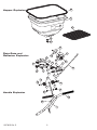
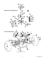
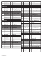
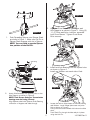
Operator's Manual
Model P40/S40 Series
IMPORTANT This manual contains information for the safety
of persons and property. Read it carefully before
assembly and operation of the equipment!
Spyker Spreaders
Contact Us at 800.972.6130
©2011 Brinly-Hardy Co.
1007895 Rev. D
62
Hopper Explosion
27
69
63
28
29
15
24
Rate Gate and
Deflector Explosion
20
26
19
21
25
24
6
4
22
5
17
19
64
7
72
8
73
4
12
73
6
3
2
5
72
6
Handle Explosion
65
68
1
1007895 Rev. D
2
16
14
44
Spinner/Axle Explosion
70
47
45
43
53
58
48
50
51
55
49
49
59
56
14
50
52
40
54
33
57
60
3
3
18
Frame Explosion
18
3
9
6
3
18
6
6
42
3
6
4*
42 40 33
13
13
3
4*
6
3
3
41
61
41 43
3
11
61 41
6
9
10
*As needed for shimming
3
1007895 Rev. D
Item Part Number
1
Qty Description
Item Part Number
Qty Description
1007770-01
1
Handle Stainless
35
N/A
Number Not Used
1008052-10
1
Handle Painted
36
N/A
Number Not Used
2
1007773
1
Control Lever
37
N/A
Number Not Used
3
05-90-0054
12
1/4" x 1-1/2" Bolt, SS
38
N/A
Number Not Used
4
05-92-0008
6
1/4" Washer, SS
39
N/A
Number Not Used
5
05-94-0051
2
Nylon Flange Bushing
40
05-90-0065
1
6
SS-91-0004
17
3/16" x 1-3/4" Clevis
Pin
7
05-90-0121
1
1/4" x 3/4" Bolt, SS
41
05-92-0004
3
Flat Washer, SS
8
1007828
2
Knob Half
42
05-95-0016-JD
2
Wheel
9
1007774-01
1
Axle Support Stainless
43
05-90-0040
1
Rue Ring Locking Pin
1008055-10
1
Axle Support Painted
44
SS-94-0012
1
Spreading Spinner
1007777-01
1
Hopper Support Stainless
45
SS-90-0002
1
1/8" x 7/8" Roll Pin
1008058-10
1
Hopper Support Painted
46
N/A
1007794
2
Cross Brace Stainless
47
05-97-0037
1
Spinner Shaft, SS
1008061-10
2
Cross Brace Painted
48
SS-90-0001
1
1/8" x 3/4" Roll Pin
12
1007811
1
Control Linkage Assembly
49
05-90-0093
2
5/8" Gearbox Bushing
13
1007888
2
1/4" x 2-1/4" Bolt, SS
50
05-90-0094
2
14
SS-92-0002
2
Felt Washer
3/8" Spinner Shaft
Bushing
15
05-94-0078
2
Pine Tree Clip
51
05-90-0096
1
3/16" x 1" Dowel Pin, SS
16
SS-96-0003
1
Agitator Wire
52
05-94-0033
1
Bevel Gear
17
05-94-0043
1
Accuway® Diffuser
53
05-94-0034
1
Pinion Gear
18
05-94-0064
5
Nylon Washer
54
05-288-1027
1
19
05-94-0097
2
Rate Gate Guide
Nylon Spacer Retaining
Pin
20
05-48-1015
1
Dial Mount Retainer
55
05-90-0097
8
#10 x 5/8" Flanged
Head Bolt, SS
21
05-46-2211-T
1
Accuway® Screw
Assembly
56
05-91-0008
8
#10 Nylon Locknut, SS
22
05-48-1113-T
1
Rate Gate & Dial Assy
57
05-94-0037
1
Gear Box Cover Front
23
SS-94-0006
1
Plastic Dial
58
05-94-0038
1
Gear Box Cover Rear
24
1008431-01
1
Rate Gate Link
59
05-98-0111
1
Grease Zerk
25
05-94-0099
1
Dial Mount
60
1007781
1
Axle
26
05-94-0068
1
Rate Gate
61
F-283
2
Axle Bearing
27
1007847
1
Hopper
62
05-94-0065
1
Hopper Cover
28
F-574
1
Bearing
63
1008022
1
Screen
29
B1HF577
1
5/8" E-Ring
64
05-46-1014
1
Control Rod
30
N/A
Number Not Used
65
SS-94-0013
2
Handle Grip
31
N/A
Number Not Used
66
N/A
Number Not Used
32
N/A
Number Not Used
67
N/A
Number Not Used
33
05-90-0102
68
05-99-0063
1
On-off Decal
34
N/A
69
05-93-0075
1
Spyker Accuway® Label
70
1007818
1
Spinner/Axle Assembly
71
N/A
72
1001255
2
1/4" x 1" Bolt, SS
73
1001554
2
Nylon Washer
10
11
1007895 Rev. D
1
1/4" Nylon Locknut, SS
Hairpin Cotter, SS
Number Not Used
4
Number Not Used
Number Not Used
Figure 3
3.
Figure 1
1.
Push Spreading Spinner onto Spinner Shaft
as shown in Figure 1. Make sure Roll Pin in
Spinner Shaft engages with slot in Spinner.
NOTE: You may need to tap the Spinner
into position on the Roll Pin.
Align the Cross Braces to the Hopper and
Axle Supports as shown in Figure 3. Using (4)
1-1/2" Bolts and Nylon Locknuts, assemble
both Cross Braces. Tighten Cross Brace
Bolts securely.
Figure 4
Zerk Fitting
4.
Install both Axle Bearings into the square holes
as shown in Figure 4.
Install one Washer onto each side of Axle.
Figure 2
Figure 5
2.
Insert Axle Assembly into square holes on the
Axle Support as shown in Figure 2.
NOTE: Zerk Grease fitting on Transmission
housing must be facing forward.
Align Spinner shaft with Spinner Shaft Bearing
on bottom of hopper and slide through.
5.
5
Locate the hole on Axle closest to the Axle Bearing
and Washer. Install Wheel (valve stem out) onto
Axle as shown in Figure 5.
Line up the hole on the wheel with hole on the Axle
shaft.
Push Clevis Pin through the hole and pin in place
using the Hair Pin.
1007895 Rev. D
Figure 6
Figure 8
8.
6.
Install Linkage to Lever as shown in Figure 8.
Install Wheel on the opposite side of the Axle
(valve stem out) until it touches Axle Bearing and
Washer. Install Washer onto Axle.
Push Rue Ring Locking Pin through Axle hole.
NOTE: Rue Ring Locking Pin will snap into
position as shown in Figure 6.
Turn Spreader assembly over and place on
ground.
Figure 9
Figure 7
7.
9.
Inside the hopper, assemble the Felt
Washer and Agitator Wire onto the Spinner Shaft as shown in Figure 7.
NOTE: Notice orientation and sweep of
Agitator Wire (Shown in Figure 7).
1007895 Rev. D
6
Turn Handle Assembly sideways and install
Linkage into Rate Gate Lever as shown in
Figure 9.
Figure 11
Figure 10
10. Attach Handle Assembly to Frame using (4)
1/4 x 1-1/2" Bolts and 1/4" Nylon Locknuts
as shown in Figure 10.
11. Install Handle Grips on Handle of Spreader as
shown in Figure 11.
READ BEFORE USING
OPERATE SAFELY
Do not wear loose fitting clothing that can get caught in
moving parts.
Keep bystanders away when you operate this machine.
Use this machine for intended purpose only.
Always wear eye protection when operating the
equipment.
Do not let children or an untrained person operate
machine.
Stay alert for holes in the terrain and other hidden
hazards.
Keep all parts in good condition and properly installed.
Fix damaged parts immediately. Replace worn or broken
parts.
Watch out for traffic when crossing or near roadways.
Before you operate any feature of this machine, observe
your surroundings and look for bystanders.
Do not modify the machine or safety devices.
Unauthorized modifications to the machine may impair
its function and safety, and void the warranty.
Always wash hands after contact with fertilizers and
pesticides.
Do not let anyone sit or ride on equipment during
operation. Keep riders off attachment.
Keep all nuts, bolts and screws tight to be sure the
equipment is in safe working condition.
Wear substantial footwear and long trousers. Do not
operate the equipment when barefoot or wearing open
sandals.
7
1007895 Rev. D
READ BEFORE USING
Become Familiar With The Operation Of The Spreader Before
You Put Material In The Hopper
•
Practice walking with the spreader, opening and
closing the rate gate at the appropriate times.
•
Travel at a constant speed and operate the spreader
lever position. Remember: Open the rate gate after
the spreader is in motion at operating speed (about
3 mph, or at a brisk walking pace).
•
dial setting on the low side. If the setting proves to
be too low, cover the area more than one time. A
higher setting can be used when a proven dial setting is
established.
Remember: Published dial settings are
approximate only. The operation of the spreader, the
condition of the material (damp or dry or over-pulverized)
and weather conditions, are all contributing factors.
For these reasons, it is often a good idea to spread the
area 2 times - or one-half rate - in cross directions (SEE
INFORMATION ON ONE-HALF RATE DIAL SETTINGS).
One-half rate dial settings are highly recommended under
damp and humid conditions.
Close the rate gate while spreader is still at
operational speed.
Dial Setting Information
The RATE DIAL has 9 numbers with 10 stops between
each number. This allows for accurate control of the
spreading rate. The dial is set with only a turn, it will
automatically lock into the set position. LINE UP THE
DIAL NUMBER WITH THE DIAL INDICATOR.
Rotary Agitator
Use the rotary agitator only if needed. Free-flowing,
lump-free materials will not require the agitator. The
rotary agitator is easily installed or removed. Note the
clockwise rotation and sweep. Place felt washer around
spinner shaft before inserting agitator.
Rate Dial
•
The spread width ranges from 4 - 12 ft. wide
depending on the volume/density, particle size of the
material, and rate of travel.
•
The spread thins or feathers at the outer edges,
eliminating sharp, "Edge Of Spread" lines which
cause stripes and streaks. Extra coverage can be
given under trees and other heavy feeding areas
without showing "Edge Of Spread" lines.
•
Gaps and double overlaps are less likely. Small
errors in travel are forgiven and do not show.
WARNING: When spreading products containing
herbicides, exercise extreme caution with respect to
careless spreading and to wind-drift.
Contact Of Some Products On
Some Plants Can Be Fatal
If a dial setting is not found, use the size and weight
comparison table found in this manual. Determine a
1007895 Rev. D
8
READ BEFORE USING
•
Now You Are Ready To Put
Material In The Hopper
WARNING: Avoid Injury! Chemicals can be
dangerous. Avoid injury to operators or bystanders.
•
Make sure the rate gate is in the closed position.
•
Read chemical container label for handling
instructions. A Material Safety Data Sheet (MSDS)
should be supplied by the chemical dealer and
provides proper safety information.
•
Wear proper clothing and safety equipment while
handling or applying chemicals.
•
Prohibit all smoking, drinking, and eating around
chemicals.
•
When spreading products containing herbicides,
exercise extreme caution with respect to careless
spreading and to wind-drift. Contact Of Some
Products On Some Plants Can Be Fatal.
•
•
Tip: When not spreading, and if pushing the spreader
some distance, tip the spreader so only the idle wheel is
on the ground.
Header
3’
Clean and oil spreader immediately after each use.
Method #1 - Wipe spreader thoroughly with an oily cloth.
Oil all bearings and bearing areas.
Now You Are Ready To Spread
•
Keep the impeller level when spreading.
•
DO NOT overload. Maximum capacity is 50 lbs.
•
DO NOT use on windy days.
•
Spread header strips at the ends of the area
OPPOSITE of the direction of spreading. This will
provide a "turn-around" area, an area to re-align the
spreader for the return spread.
•
Example shown is for 6 ft. wide spread. Make the
first spread pass at one-half the spread width from
the edge of the spreading area or in this case,
approximately 3 feet (or one big step).
•
Additional spreading passes will be at the full spread
width or approximately 6 ft. apart.
•
TAKE A SIGHTING AT THE FAR END. Keep your eye
on the sighting as you spread. You will not need
to wonder where you are or where you have been.
Continue until spreading is completed.
6’
Cleaning The Spreader Is Part
Of The Spreading Job
When filling hopper with material, always use screen
to help break up clumps.
Keep spinner blade clean. Excess material build-up
can cause an uneven spread pattern.
6’
Header
Fill the spreader on a flat, level surface only. Fill on
sidewalk, driveway, cardboard, etc. to avoid material
loss.
•
Left over fertilizer can be spread under trees and
other high feeding areas without showing "edge of
spread" lines.
Method #2 - Wash, rinse, and dry the spreader. Note:
Drying takes time. Moisture trapped in bearing areas is
slow to go. Immediately after drying - oil all bearings and
moving parts. Make certain all operations are thorough.
NOTE: Good "Dry Cleaning" is preferable to poor "Wet
Cleaning".
•
It is virtually impossible to have rust and corrosion on
a clean, dry, oiled surface.
•
Again - just before using - oil all bearings and moving
parts.
•
In storage, ideally the spreader should be hung by
the handle. In any case, do not pile weight on the
spreader, as excess weight over a period of time can
distort the tires.
Oil Bearings And All Moving
Parts
Make sure the spreader is running freely!
9
1007895 Rev. D
ACCUWAY® - What It Does
The Accuway® Spread Pattern Equalizer Balances the
spread pattern - Bulls Eye - Dead to the Center of the
Spreader.
All products. All spreading conditions.
Skewing is eliminated. Does not change the spread
width.
ACCUWAY® - How It Works
Accuway® shifts the material placement on the spreader
spinner fan. This in turn, balances the pattern heavier to
the right or heavier to the left.
Spread pattern can be affected by many variables such
as humidity, temperature, wind, spreader condition,
speed of travel, material size and weight. Because of
these variables, the diffuser must be adjusted for each
type of application. Proper adjustment will minimize
skewing and uneven coverage.
Adjustment is very sensitive. Turning the Accuway®
Diffuser Knob just a little will result in a drastic change to
the spread pattern.
The Accuway® Diffuser Plate has a front and a rear
ramp. Never adjust so that the diffuser plate splits the
material flow to both the front and rear ramp at the
same time.
If the spreader is spreading to the left of center, turn
the diffuser knob counterclockwise fully. Then adjust
clockwise until the edge of the diffuser plate centers the
spread.
If the spreader is spreading to the right of center, turn
the diffuser knob clockwise fully. Adjust counterclockwise
until the edge of the diffuse plate centers the spread.
NEVER USE ACCUWAY FRONT AND REAR RAMPS TO
SPLIT THE PRODUCT FLOW. Use only the front side or
the back side. With proper adjustment you should be
able to achieve a balanced spread pattern.
TROUBLESHOOTING
Spreader does not sit flat
Deflector shut off is binding
and will not open/close
properly
1007895 Rev. D
The "feet" or the flattened
portion of the spreader hopper
support tubes are not bent
equally.
Shut off plate is jammed with
debris.
10
Using a hammer or pliers,
bend the feet to be equal with
each other.
Thoroughly wash out hopper
and shut off plates with water.
Ensure debris is not stuck
between shut off plate and
rate gate plate.
NOTE: Dial Settings Are Approximate Only !
Product
Particle Size
Fine Pellets
Mixed Fine
Pellets
Small Pellets
Lbs. per
1000 sq. ft.
Dial Settings
Full Rate
Once Over
1
3.6
3.1
2
3
4.0
4.2
3.5
3.7
2
3.7
3.2
4
6
4.7
5.2
4.1
4.5
2
3
2.2
4
4.2
4.5
3.7
6
2
3
Large Heavy
Pellets
3
3.7
4
4.7
4
6
3.5
4.2
5.2
3.8
4.5
2
4
6
3.8
4.9
5.9
3.3
4.1
4.9
2
Medium Pellets
And Granuals
4
3.5
4.2
1
Nitrogen Pellets
Medium Size
Dial Settings
Half Rate
Twice Over
3
GRASS SEED SPREADING CHART
Product
Bag
Weight
Sq. Ft.
Coverage
Dial Setting
Full Rate
Blue Grass or Red Top
.5 lbs.
1,000
1.25
4
1 lbs.
1,000
2.0
4
2 lbs.
1,000
2.5
4
.5 lbs.
1,000
2.5
4
1 lbs.
1,000
3.0
4
2 lbs.
1,000
3.5
4
2 lbs.
1,000
2.75
2.25
6
3 lbs.
1,000
3.0
2.5
6
4 lbs.
1,000
3.25
2.75
6
2 lbs.
1,000
6.0
6
4 lbs.
1,000
7.0
6
6 lbs.
1,000
7.0
6
2 lbs.
1,000
6.0
6
4 lbs.
1,000
7.0
6
6 lbs.
1,000
7.75
6
4 oz.
1,000
1.9
8
8 oz.
1,000
2.1
8
12 oz.
1,000
2.5
8
4 lbs.
1,000
4.5
3.75
7
5 lbs.
1,000
4.75
4.0
7
6 lbs.
1,000
5.0
4.25
7
Park, Merion, Delta, or Kentucky Bluegrass
Hulled Bermuda
Mixtures Including Coarse Seeds
Rye Grasses or Tall Fescue
Dichondra
Pensacola Bahia
11
Dial Setting
Half Rate
Spread
Width
1007895 Rev. D
1 YEAR LIMITED WARRANTY
This is warranted to the original purchaser only. Spyker will replace parts
with defects in materials and workmanship, for a period of one year from the
date of purchase.
For Spyker Spreaders–a Brinly-Hardy Company, products employing metal
gear systems, pinion and bevel, these metal gears, only, not inclusive of any
other parts or materials, are warranted for the life of the spreader, not to
be used for replacement or repair past original purchase.
Spyker Spreaders will not be liable for any loss, damage or expense including,
but not limited to, consequential or incidental damages, arising from the
operation, condition or use of the item. The sole and exclusive remedy
against Spyker Spreaders being the replacement of the defective parts. This
warranty gives you specific legal rights, and you may also have other rights
which vary from state to state.
This express warranty, which is applicable only to the original
purchase, is in lieu of and excludes all other warranties, whether
expressed or implied by operation of law or otherwise, including any
warranty of merchantability or fitness for particular purpose.
SPYKER SPREADERS
Jeffersonville, IN 47130 USA
Phone: 800.972.6130
1007895 Rev. D