1
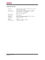
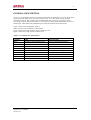
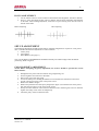
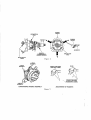
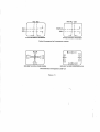
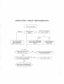
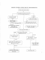
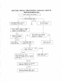
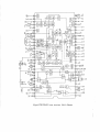
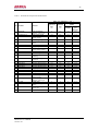
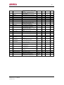
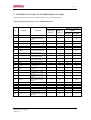
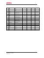
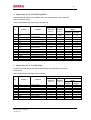
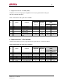
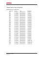
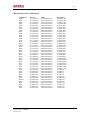
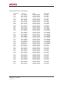
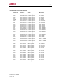
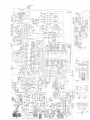
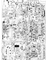
Colour TV
Service Manual
2
CHASSIS: CN-9
MODEL:
CT-14XJ9N
3
CONTENT
Specifications ....................................................................................... 4
General description .............................................................................. 5
Connector view .................................................................................... 8
Safety instructions .............................................................................. 11
Circuit adjustments ....................….................................................... 12
Set-up adjustment .............................................................................. 13
Service mode general instructions ...................................................... 15
Service mode adjustment ................................................................... 19
Main repairing flow diagram .............................................................. 20
Main ICs description and repair data offering .................................... 26
Spare parts list .………………………………………………………..35
Appendix:
Exploded view ………………………………………………………..49
Circuit diagram ……………………………………………………….50
Print lay-out of main board …………………………………………...51
Model No: CT-14XJ9N
Version 1.0
4
SPECIFICATIONS
RF system:
Video system:
Receiving channel:
Programs Preset:
Antenna. input:
Picture tube:
Audio output:
Power supply:
Weight:
Dimensions:
Power consumption:
Model No: CT-14XJ9N
Version 1.0
Color system: PAIA.43, NTSC3.58, NTSC4.43, PAL-M, PAL-N
Sound system: D/K, I, M, B/G
PAIA.43, NTSC4.43, NTSC3.58, PAL-M, PAL-N (50/60Hz)
VHF: Cl~C12 (49.75 ~ 85.25MHz, 168.25 ~ 216.25MHz)
UHF: C 13~C57 (471.25 ~ 863.25MHz)
CATV: Zl~Z7 (111.0 ~ 167.0MHz)
ZS~Z35 (223.0~447.0MHz)
236
75Ù (imbalance)
Effective screen dimension: 406mmx305mm; Flat-square tube
Main channel: 5W+5W (THD=7%)
AC 150~260V (50Hz )
~26kg
5 66mm(w) x 4551mn(h) x 480mm(d)
~87W (AC 220V 50Hz)
5
GENERAL DESCRIPTION
CN-9 is a CTV monolithic chassis. It introduces a monolithic IC TB1231N to carry out all the small
signal processing. TB1231N is a kind of IC used by color TV in PAL/NTSC system, which is
controlled by Inter IC Bus. Together with the SECAM decoder TA1275Z, it can form a signal
processing circuit for multi-system color TV. This chassis is used in many fashionable TV receiver
technologies, which makes the performance/price reach the advanced level of the world.
Figure 1 shows the block diagram of CN-9.
Table 1 provides CN-9 mainly ICs and functions.
Figure 2 shows the whole set power supply system for CN-9
Figure 3 shows the system control circuit of CN-9
Table 1: CN-9 mainly ICs and functions
Location
N001
N002
N945
NM01
N101
N202
N201
N401
N601
N602
Type
CH0807(TMP87CM38N-3673)
AT24C04
HS0038
TC9028F-022
LA7910
HEF4052
TB 1238AN
TA8403
TDA7057AQ
CD4066
Model No: CT-14XJ9N
Version 1.0
Mainly function
System control microprocessor
Memory
Remote control receiver
Remote control transmitter
Band decoder
Sound system switching
Small signal processing
Vertical output power amplifier
Audio power amplifier
Audio TV/AV switching
11
SAFETY INSTRUCTION
WARNING: BEFORE EXAMINING AND SERVICING THIS CHASSIS, READ CAREFULLY
THE FOLLOWING SAFETY INSTRUCTIONS.
X-RAY RADIATION PRECAUTION
1.
The EHT must be checked every time the receiver is serviced to ensure that the CRT does not
emit X-ray radiation as result of excessive EHT voltage. The nominal EHT for this receiver is
27.5kv at zero beam current (minimum brightness) operating at AC 220V. The maximum
EHT voltage permissible in any operating circumstances must not exceed 30KV. When
checking the EHT, use the High Voltage Check procedure in this manual using an accurate
EHT voltmeter.
2.
The only source of X-RAY radiation in this receiver is the CRT to prevent X-ray radiation you
should use the same type of CRT when replacing it.
3.
Some components used in this receiver have safety-related characteristics preventing the CRT
from emitting X-ray radiation. For continued safety, replacement component should only be
made after referring the Product Safety notice below.
SAFETY PRECAUTION
1.
2.
3.
4.
5.
6.
The high voltage in the TV reaches to 27.5KV when the TV is in operation. Be more careful
during opening the back cover.
a. The high voltage existing in the TV is very dangerous. Refer servicing to qualified
personnel only.
b. Before removing the high voltage cap, discharge the anode of the CRT and the chassis in case of electric shock.
c. Wear a pair of goggles when handling the CRT to void broken pieces damaging your
eyes.
d. Do not hold the CRT neck in case of causing damage to the CRT.
When the power cord needs replacing, use the same one as stated in this manual.
Voltage exists between the hot and cold ground when the TV is in operation. Install a
separation transformer during repairing or connecting to any tester for the sake of safety. The
power of the separation transformer should be beyond rated overall power.
When replacing a burnout fuse, use the one with the same specifications as the original.
When replacing old wire, wind new one round the shaft to weld. When replacing components
with safety in performance, use the same type as that specified by this manual and install it in
the former way.
Never place wire near high-temperature or high-voltage components.
SAFETY CAUTIONS FOR PRODUCTS
Many electric and mechanical components in CN-9 chassis have special, safety performances, which
are always neglected. Even if replacing them with some components with the same voltage and power,
you can not get effective protection to X-ray. In the circuit diagram, these special electric components
are indicated by the special mark ! , and on the shadow. When replacing any of them, use the one with
the same specifications as the originals. Otherwise, it may cause X-ray radiation and damage to overall
safety.
Model No: CT-14XJ9N
Version 1.0
12
CIRCUIT ADJUSTMENTS
GENERAL INFORMATIONS
All adjustment are thoroughly checked and corrected when the receiver leaves the factory. Therefore
the receiver should operate normally and produce proper colour and B/W pictures upon installation.
However, several minor adjustments may be required depending on the particular location in which the
receiver is operated.
This receiver is shipped completely in carton. Carefully draw out the receiver from the carton and
remove all packing materials. Power cord into a convenient 220 volts 50 Hz AC two pin power outlet.
Turn the receiver ON. Check and adjust all the customer controls such as BRIGHTNESS, CONTRAST
and COLOUR Controls to obtain natural colour or B/W picture.
AUTOMATIC DEGAUSSING
A degaussing coil is mounted around the picture tube so that external degaussing after moving the
receiver is normally unnecessary, providing the receiver is properly degaussed upon installation. The
degaussing coil operates for about 1 second after the power to the receiver is switched ON. If the set is
moved or faced in a different direction, the power switch must be switched off at least 30 minutes in
order that the automatic degaussing circuit operates properly. Should the chassis or parts of the cabinet
become magnetized to cause poor colour purity, use an external-degaussing coil. Slowly move the
degaussing coil around the faceplate of the picture tube, the sides and front of the receiver and slowly
withdraw the coil to a distance of about 2m before disconnecting it from AC source. If colour shading
still persists, perform the COLOUR PURITY ADJUSTMENT and CONVERGENCE
ADJUSTMENTS procedures.
POWER SUPPLY ADJUSTMENT
CAUTION: +B voltage has close relation to high voltage. To avoid X-ray radiation, +B voltage should
be to +115V.
1.
2.
3.
Set RVS01 to the mechanical center and AC power supply to 220-+2V.
Connect a digital voltmeter to two pins of C822,' and then turn on the TV.
Receive Philips test signal.
4. Adjust RVS01 to make the voltmeter read 115±0.5V.
HIGH VOLTAGE EXAMINATION
CAUTION: No high voltage adjustment should be done in CN-9 chassis.
1.
2.
3.
4.
Connect a precise high voltmeter to the second anode of the CRT.
Turn on the TV and set the brightness and contrast to minimum (i.e. set beam current of the
CRT to zero).
The high voltage tested should be 27.5 ± 0.5KV.
Set the brightness to minimum or maximum, and ensure high voltage not beyond limitation of
30KV in any case.
Model No: CT-14XJ9N
Version 1.0
13
FOCUS ADJUSTMENT
1.
2.
Use the remote control to set the contrast to maximum and the brightness, chroma to medium.
Set H. V. lines near Philips picture center to thinnest with the focus adjustment potentiometer
on the FBT. After finishing adjustment, ensure that no poor focusing exist near the center or
around of the frame.
Before Adjusting
After adjusting
SET-UP ADJUSTMENT
The following adjustments should be made when a complete realignment is required or a new picture
tribe is installed. Perform the adjustments in order as follows:
1. Colour purity
2. Convergence
3. White Balance (See page 17)
Note: The PURITY/CONVERGENCE MAGNET assembly and rubber wedges need mechanical
positioning. Refer to figure 4.
COLOUR PURITY ADJUSTMENT
NOTE: Before attempting any purity adjustment, the receiver should be operated for at least
fifteen minutes.
1.
2.
3.
4.
5.
6.
7.
8.
Demagnetize the picture tube and cabinet using a degaussing coil.
Set the brightness and contrast to maximum
Receive the green raster test signal.
Loosen the clamp screw holding the deflection coil and slide, the backward or forward to
provide vertical green belt (zone) in the picture screen.
Remove the Rubber Wedges.
Rotate and spread the tabs of the purity magnet (See figure 5) around the neck of the picture
tube until the green belt is in the centre of the screen.
Slowly move the deflection coil forward or backward until a uniform green screen is obtained.
Tighten the Clamp screw of the coil temporarily.
Check the purity of the red and blue raster.
Model No: CT-14XJ9N
Version 1.0
15
CONVERGENCE ADJUSTMENTS
NOTE: Before a attempting any convergence adjustments, the receiver should be operated for at
least fifteen minutes.
CENTRE CONVERGENCE ADJUSTMENT
1.
2.
3.
4.
5.
6.
Receive the pane pattern test signal.
Set the brightness and contrast for well-defined pattern.
Adjust two tabs of the 4-Pole Magnets to change the angle between them (See figure 5) and
superimpose red and blue vertical lines in the centre area of the picture screen.
Turn the both tabs at the same time keeping the angle constant to superimpose red and blue
horizontal lines at the centre of the screen.
Adjust two tabs of 6-Pole Magnets to superimpose red/blue line (land green line. Adjusting
the angle affects the vertical lines and rotating both magnets affects the horizontal lines.
Repeat adjustments 3, 4, 5 keeping in mind red, green and blue movement, because 4-Pole
Magnets and 6-Pole Magnets have mutual interaction and make dot movement complex.
CIRCUMFERENCE CONVERGENCE ADJUSTMENT
1.
2.
3.
4.
5.
6.
7.
8.
9.
Loosen the clamping screw of defection coil slightly to allow the coil to tilt.
Temporarily put a wedge as shown in figure 4. (Do not remove cover paper on adhesive part
of the wedge.)
Tilt front of the deflection coil up or down to obtain better convergence in circumference. (See
figure 6) Push the mounted wedge into the space between picture tube and the coil to fix the
coil temporarily.
Put other wedge into bottom space and remove the cover paper to stick.
Tilt front of the deflection coil right or left to obtain better convergence in circumference. (See
figure 6)
Keep the deflection coil position and put another wedge in either upper space. Remove cover
paper and stick the wedge on picture tube to fix the coil.
Detach the temporarily mounted wedge and put it in another upper space. Stick it on picture
tube to fix the coil.
After fixing three wedges, recheck overall convergence. Tighten the screw firmly to fix the
coil and check the coil is firm.
Stick three adhesive tapes on wedges as shown in figure 4.
SERVICE MODE GENERAL INSTRUCTIONS
1. ENTERING TO SERVICE MODE
Use the user remote receiver K10 seriers. Set the volume to minimum. Press the MUTE button on
Remote Control. Keep pressing the MUTE button, press MENU button on TV set until the
character D and an adjustment item appears on the screen.
2. SELECTING THE ADJUSTING ITEMS
Every pressing of the MENU “ ” or “ ” button on remote control transmitter changes the
adjustment items in the following BUS DATA table.
Model No: CT-14XJ9N
Version 1.0
17
Table 2 The BUS DATA FOR CN-9
Number
1
2
3
4
5
6
7
8
9
10
11
12
13
14
15
16
17
18
19
20
21
22
23
24
25
26
27
28
29
30
31
32
33
34
35
Adjustment Item
RCUT
GCUT
BCUT
GDRN
BDRN
CNTX
BRTC
COLC
TNTC
COLP
COLS
SCNT
CNTC
CNTN
BRTX
BRTN
COLX
COLN
TNTX
TNTN
ST3
SV3
ST4
SV4
SHPX
SHPN
TXCX
RGCN
VM0
VM1
HPOS
VP50
HIT
HPS
VP60
Model No: CT-14XJ9N
Version 1.0
Adjustment Function
Red Dark Balance
Green Dark Balance
Blue Dark Balance
Green Light Balance
Blue light Balance
Sub contrast max
Sub-bright centre
Sub color center (NTSC)
Sub tint center
Sub color center (PAL difference)
Sub color center (SECAM)
Sub contrast
Sub contrast center
Sub contrast min
Sub bright max (difference)
Sub bright min (difference)
Sub color max (difference)
Sub color min
Sub tint max (difference)
Sub tint min (difference)
Sub sharp center (3.58NTSC TV)
Sub sharp center (3.58NTSC AV)
SUB SHARP CENTER (OTHER TV)
Sub sharp center (other AV)
Sub sharpness max (difference)
Sub sharpness min (difference)
Text RGB contrast max
Text RGB contrast min
V/C/D mode data 0
V/C/D mode data 1
Horizontal center of 50 Hz
Vertical centering of 50 Hz
Vertical amplitude of 50 Hz
Horizontal centering difference of 50/60 Hz
Horizontal centering difference of 50/60 Hz
Type Data
40
42
64
3B
3B
3F
2A
40
40
00
10
08
20
08
1C
20
35
00
28
28
20
20
20
20
1A
1A
29
16
3C
20
00
07
23
10
04
18
Number
36
37
38
39
40
41
42
43
44
45
46
47
48
49
50
51
52
53
54
55
56
57
58
59
60
61
62
63
64
65
Adjustment Item
HITS
VLIN
VSC
VLIS
SBY
SRY
R AGC
AFT
HAFC
V25
V50
BRTS
SELF
SELF VCO
SELF AGC
SELF BRTC
SELF CNTC
SELF TNTC
SELF COLC
PNUM
VHFL-L
VHFL-H
VHFH-L
VHFH-H
UHF-L
UHF-H
VM2
OSD
OPT
MODE
Model No: CT-14XJ9N
Version 1.0
Adjustment Function
Vertical amplitude deflection of 50/60 Hz
Vertical line of 50 Hz
Vertical S correction
Vertical line deflection of 50/60 Hz
SECAM B-Y
SECAM R-Y
RF AGC
PIF VCO center
AFC gain
Volume 25%
Volume 50%
Sub bright (difference)
TB1231N P40UT select
Self adjust VCO initial data
Self adjust AGC initial data
Self adjust BRTC initial data
Self adjust CNTC initial data
Self adjust TNTC center initial data
Self adjust COLC initial data
Protect number
Factory ASM VT limit of VHFL low byte
Factory ASM VT limit of VHFL high byte
Factory ASM VT limit of VHFH low byte
Factory ASM VT limit of VHFH high byte
Factory ASM VT limit of UHF LOW byte
Factory ASM VT limit of UHF high byte
TB1231N V/C/D mode data
OSD position
Option
Factory data
Type Data
25
0D
0E
0D
08
08
IF
IF
00
3A
57
00
00
80
80
80
20
00
10
7F
50
03
50
03
00
03
00
07
77
00
19
3. ADJUSTMENT THE DATA
Pressing of the MENU " " or " " button on remote control transmitter will change the value of
data, in the range from 00 to FF. The variable range depends on the adjusting item.
4. EXIT FROM SERVICE MODE
Use the keyboard on remote control transmitter or TV set to turn off the TV once.
SERVICE MODE ADJUSTMENT
1. AFT VOLTAGE ADJUSTMENT
Enter the TV to the SERVICE mode. Press the PICTURE MODE SELECTION button on the remote
control transmitter once the TV will adjust the AFT automatically. When the adjustment is over, the
characters AFT-OK will appear on the screen.
2. SUB-BRIGHTNESS
1.
2.
3.
Receive colour signals.
Set the contrast to maximum and the brightness to medium.
Set the chroma to medium. Enter the TV to the SERVICE mode. Select the BRTC item by
pressing the item adjustment button on the remote transmitter, and set the data to 2A by pressing
the data adjustment button. Operate the TV for 5 min in the mode.
4. Adjust the BRTC data until fuzzy picture does not appear on the high bright area of the screen and
too dim picture not on the low-bright area.
5. Set the contrast and brightness to maximum or minimum, and then test normal picture alternation.
6. If the picture does not become dark when the contrast and brightness are set to minimum, or not
become bright when set to maximum, then adjust the BRTC data to get normal picture.
3. WHITE BALANCE ADJUSTMENT
1.
2.
3.
4.
5.
Turn on the TV and preheat it for over 7 minute.
Use the remote control to set the contrast to maximum and the brightness to medium.
Set the chroma to minimum.
Enter the TV to the SERVICE mode, and set the following data without changing other items.
RCUT ............40
GCUT ............42
BCUT ............64
GDRN ............3B
BDRN ............3B
Pull out the external antenna and press the MUTE button once on the remote control until a bright
horizontal line appears on the screen. Adjust the GCUT data to get 160V+0.5 green gun voltage
across the Y board.
Adjust the RCUT and BCUT data according to the given at Step 4 so that the bright horizontal line
turns to yellow, then to white.
4. HORIZONTAL CENTERING ADJUSTMENT
Enter the TV to the service mode, and receive Philips test signal. Select the HPOS or HPS item by
pressing the item adjustment button on the remote control, and adjust horizontal picture position in the
centre of screen by pressing the data, adjustment button.
5. VERTICAL CENTERING ADJUSTMENT
Enter the TV to the service mode, and receive Philips test signal. Select the VPS0 or VP60 item by
pressing the item adjustment button on the remote transmitter, and adjust vertical picture position in the
centre of screen by pressing the data adjustment button.
Model No: CT-14XJ9N
Version 1.0
20
6. VERTICAL AMPLITUDE ADJUSTMENT
Enter the TV to the service mode, and receive pane test signals. Select the HIT item by pressing the
item adjustment button on the remote transmitter, and adjust vertical amplitude by pressing the data,
adjustment button so that vertical amplitude lacks a little. Continue to adjust vertical amplitude by
pressing the data adjustment button until the first bar on pane signal touches edge of screen.
7. HORIZONTAL AMPLITUDE ADJUSTMENT
Receive Philips test signals. Adjust the horizontal amplitude adjustment inductance L506 so that the
edge of the CRT covers the right and left borderlines of Philips picture by 1/3 grille.
8. BUS DATA INITIALIZATION
When the BUS DATA of TV is confused, enter the TV to the service mode. Press the SLEEP button on
the Remote Control will initialize the BUS DATAS for all adjustment items.
MAIN REPAIRING FLOW DIAGRAM
The following flow diagrams are for the corresponding troubleshooting, which can help you find the
causes for troubles. Check as the order shown on the flow diagrams, you can find the defective
component.
Model No: CT-14XJ9N
Version 1.0
26
MAIN ICS DESCRIPTION AND REPAIR DATA OFFERING
1. INTRODUCTION FOR IC TB1238AN (N201)
TB1238AN is a PAL/NTSC system color TV specific monolithic IC currently developed by Toshiba
Co., which is controlled by Inter IC Bus. TB1238AN includes a picture IF processing circuit, a sound
IF processing circuit, PLL video detection circuit, PLL sound frequency discrimination circuit, a
luminance signal processing circuit, PAL/NTSC chro-ma signal processing circuit and RGB signal
processing circuit. TV/AV switching circuit and Horizontal/Vertical scanning small signal processing
circuit etc.
Figure 7 shows the inner structure block diagram of TBI238AN.
The pin functions and repair data of TB1238AN is listed in the Table 3.
Model No: CT-14XJ9N
Version 1.0
28
Table 3 Pin functions and repair data of TB1238AN
Pin
Symbol
Function
1
DE-EMP
2
3
AUDIO OUT
IF VCC
4
5
AFT OUT
IF GND
6
7
8
IF IN
IF IN
RF AGC
9
10
11
IF AGC
APC FILTER
4.43MHZXTA
12
Y/C GND
13
14
15
16
17
18
19
20
21
YS/YM
EXT R IN
EXT G IN
EXT B IN
RGB VCC
R OUT
G OUT
B OUT
ABCL
22
V Ramp
23
24
V NFB
V OUT
25
V AGC
26
SCL
Audio deemphasis
capacitor connect pin
Audio signal output
+9V supply input for IF
amplify circuit
AFT voltage output
Ground for IF amplifier
circuit
IF signal input
IF signal input
RF amplifier AGC
control voltage output
IF amplifier AGC filter
APC filtering
4.43MHZ crystal
oscillating
Ground (Y/C signal
processor)
Y-switch signal input
Character R signal input
Character G signal input
Character B signal input
Supply input (RGB)
R output
G output
B output
automatic brightness,
contrast control
vertical Ramp generator
capacitor connect pin
V NFB input
vertical pulse signal
output
V AGC filter capacitor
connect pin
(I2C) clock line
Model No: CT-14XJ9N
Version 1.0
Index type multimeter (r=20k )
Resistance for GND
(RxlK)
'Quiescent Dynamic
state
state
Red pen
Black
(V)
(V)
measure
pen
measure
5
4.9
7.2
9.0
3.5
9
3.4
9
6.5
0.8
7.3
0.8
2
0
1.7
0
6.2
0
8.3
0
0.20
1.4
7.2
0
1.4
5.6
6.8
6.8
7
11.2
11.2
10
6
1.8
2.2
4.4
1.8
2.2
7.2
10
7.4
11.2
11.2
120
0
0
0
0
0
0.9
0.9
0.9
9
2.1
2
2.2
5.3
0
0.9
0.9
0.9
9
2.4
2.4
2.5
5.4
1
7.2
7.2
7.2
0.8
7
6.8
6.8
7.4
2
11.2
11.2
11.2
0.9
10
10
10
11
5.4
4.4
7
11
5
1
5
1
7
1
9.3
1
0.2
0.3
7.2
18
3.8
3.8
6
18.1
29
28
H VCC
29
SID/CW OUT
30
31
32
33
34
35
36
FBP IN
SYNC OUT
H VCC
DEF GND
FBP IN
VIDEO OUT
DIG. VD
37
S R-Y IN
38
39
S B-Y IN
Y IN
40
H AFC
41
EXT.VIDEO/Y IN
42
43
DIG. GND
TV.VIDEO IN
Horizontal deflection supply input
(+9V)
SECAM identification/CW
signal output
Horizontal flyback pulse input
SYNC pulse output
Horizontal excitation output
Ground (detection circuit)
Sandcastle pulse output
Video signal output
Digital circuit Supply
SESECAM R-Y signal input
CAM B-Y signal input
SECAM R-Y signal input
Luminance signal input
Connecting RC network for
horizontal AFC filter
External video/luminance signal
input
Digital circuit ground
TV. Video signal input
44
BLACK DET
45
EXT.CIN
46
Y/C VCC
47
IF DETOUT
48
LOOP Filter
49
VCO GND
50
VCO
51
VCO
52
VCO VCC
53
54
55
Limitter IN
RIPPLE FILTER
EXT AUDIO
56
FM DEC NF
9.6
9.6
4
18.3
1.8
3.8
7.2
11.2
4
4
2
0
1.5
2.8
5.3
4.8
4.8
2
0
1.4
3
5.3
6
6
0.8
0
7.2
2
4
11
4
1
0
11
2.5
5.9
2.6
2.7
7.2
11
2.6
1.1
2.6
1.1
7.2
7.2
11
12
6.8
6.8
7.2
18.5
1.6
1.6
7.2
11
0
2.8
0
3.2
0
7.2
Black level detecting filter
3.2
2.4
7.2
0
11
12
External chroma signal input
+5V supply input (Y/C processing
system)
2.9
2.9
7.2
11.5
5.2
5.2
1.6
2
IF video detected output
4.6
3.7
1
4
4.8
7.2
11
0
0
0
0
8.1
8
1
0.7
8
8
1
0.7
9
9
0.8
0.6
3.9
5.8
3.4
necting
pin
3.8
4.8
3.4
7.2
7.2
7.2
11
10
11
3.8
3.7
7
Connecting RC filter network for
phase loop circuit
Ground (IF VCO circuit)
Voltage control oscillating coil
connecting pin
Voltage control oscillating coil
connecting pin
+9V supply input (IF VCO
circuit)
Sound IF signal input
Ripple filter circuit
External audio signal input
FM direct current negative
feedback filter capacitor con
.
Model No: CT-14XJ9N
Version 1.0
1.3
30
2. INTRODUCTION FOR CPU IC TMP87CM38N-3673 (N001)
The pin functions and repair data of TMP87CM38N-3673 is listed in the table 4.
Table 4 Pin functions and repair data of TMP87CM38N-3673
Pin
Symbol
1
Vss
2
VT
3
KARA-ENA
4
MUTE
5
6
EXT-MUTE
S.ID
7
POWER
8
KARA-CLK
9
BAND1
10
BAND2
11
12
SCL1
SDA1
13
AFC IN
14
AV0
15
EXT G IN
16
EXT B IN
17
RGB VCC
18
R OUT
19
20
21
22
23
24
G OUT
B OUT
ABCL
R OUT
G OUT
B OUT
25
Y OUT
Model No: CT-14XJ9N
Version 1.0
Function
Ground
Tuning voltage output
PWM phase-reversed
wave.
NC
Sound mute signal output,
high level=Mute
NC
NC
Supply on/off control
signal output, high level =
off, low level = on
NC
Tuner band switching
control signal output
Tuner band switching
control signal output
Inter IC Bus clock line
Inter IC Bus data line 1
Automatic frequency
control input
AV switch control signal
O output
NC
Keypad analog voltage
input 1
Keypad analog voltage
input 2
Supply protect checkout
signal input, low level=
protect
NC
BUS on/off control output
Ground
OSD character It output
OSD character G output
OSD character B output
Character window
signal/fast blanking signal
for OSD
Index type multimeter (r=20k )
Resistance for GND
Quiescent
Dynamic
(RxlK)
state (v)
state (v)
Red pen
Black pen
measure
measure
0
0
0
0
1
0.1
6
19
0
0
6
21.5
4.9
0
6
21.5
0
0
0
0
6
6
13.5
23.5
4.9
0
6
21.5
0
0
6
23.5
4.9
5
6
16.7
0
0
6
14
4.3
4.5
4.3
4.5
5.8
5.6
21.3
21.3
0
1.8
6
10
0
4
6
18
0
0
0
0
4.2
4.2
6
21.5
4.2
9
6
24.8
1.8
4.9
6
24.8
0
4
0
4.4
4.5
4.5
0
3.9
0
0
0
0
6.4
6
0
1.4
1.4
1.4
28
21.5
0
1.3
1.3
1.3
4.5
0
2
2
31
26
HD
27
VD
28
OSC1
29
OSC2
30
TEST
31
XIN
32
XOUT
33
34
RESET
OPTION
35
RMT IN
36
H. SYNC
37
38
39
SCL0
SDA0
KARA
40
SYS0
41
SYS1
42
VDD
Model No: CT-14XJ9N
Version 1.0
Horizontal flyback for
OSD
Vertical sync pulse for
OSD
OSD character
oscillator pin 1
OSD character
oscillator pin 2
Test pin
I0MHZ clock
oscillation input
10MHZ clock
oscillation output
CPU reset pin
Option pin
Remote control
instructions input
Picture identification
signal input
Inter IC Bus clock line0
Inter IC Bus data line 0
ON/OFF NC
Sound system switch
control
Sound system switch
control
+5V supply input
0
3.8
5.8
19
4.9
4.7
5.6
14.8
4.8
4.9
5.6
23.8
4.8
4.9
5.6
24
0
0
0
0
1.5
0.5
6.2
24.3
2.2
2.2
4.8
24.3
5
4.9
5
4.6
5.4
6
5
14.5
3.5
3.4
6
24
1
4.5
6
15
4.7
4.7
0
0
4.8
0
6
6
6
23
23
24
0
0
6
11.3
1.2
4
6
11.3
5
5
6
8.3
32
3. Repair data for IC TDA7057AQ(N601)
TDA7057AQ is the audio power amplifier OF CN-9, the pin functions and repair data
of it is listed in the table 5.
Table 5 Pin functions and repair data of TDA7057AQ
Pin
Symbol
1
VC1
2
3
4
5
6
N.C.
VI(1)
Vp
VI(2)
S-GND
7
VC2
8
9
10
11
12
13
OUT2+
PGND2
OUT2OUT1PGND1
OUTI+
Function
Index type multimeter (r=20k )
Resistance for GND
Quiescent
Dynamic
(RxlK)
state (v)
state (v)
Red pen
Black pen
measure
measure
Control pin for direct
current volume
No connected
Audio signal input 1
Supply input pin
Audio signal input 2
Signal ground
Control pin for direct
current volume
0.96
0.96
0
2.38
15
2.38
0
0
2.38
15
2.38
0
0.98
Audio signal output 2+
Ground 2(supply circuit)
Audio signal output 2Audio signal output 1Ground l(supply circuit)
Audio signal output 1+
7.0
0
7.0
7.0
0
7.0
13.5
6.2
18.7
12.8
0
6.4
3.9
6.4
0
0.98
16.8
6.2
7.0
0
7.0
7.0
0
7.0
12.8
0
12.8
12.8
0
12.8
5.4
0
5.4
5.4
0
5.4
4. Repair data for IC LA7910(N101)
LA7910 is the band decoder of CN-9, the pin functions and repair data of it is listed
in the table 6.
Table 6 Pin functions and repair data of LA7910
Pin
1
2
3
4
5
6
7
8
9
Symbol
OUT1
OUT2
BD1
BD2
GND
VC2
OUT3
OUT4
VC1
Model No: CT-14XJ9N
Version 1.0
Function
Decoder output
Decoder output 2
Band control level input 1
Band control level input 2
Connect to ground
+33V supply input pin
Decoder output 3
Decoder output 4
+12V supply input pin
Index type multimeter (r=20k )
Resistance for GND
Quiescent
Dynamic
(RxlK)
state (v)
state (v)
Red pen
Black pen
measure
measure
0
0
5
0
0
33
0
0
12
0
0
0
0
0
13.5
12
0
12
2.1
2.1
39
22
0
5.8
1.6
0
4.1
2.1
2.1
11
10
0
25.5
1.5
12
4.5
33
5. Repair data for IC TA8403(N401)
TA8403 is the vertical output power amplifier IC of CN-9, the pin functions and repair
data of it is listed in the table 7.
Table 7 Pin functions and repair data of TA8403
Pin
1
2
3
4
Symbol
GND
OUT
Connect to ground
Field pulse output
Pump power supply input
V saw tooth pulse input
Connect to Phase
compensate capacitance
Power supply pin
Pump power supply
output
IN
5
6
Function
Vcc
7
Index type multimeter (r=20k )
Resistance for GND
Quiescent
Dynamic
(RxlK)
state (v)
state (v)
Red pen
Black pen
measure
measure
0
15
24.5
1
0
15
24.5
1.1
0
4
4.4
2.2
0
9.5
2
2.2
0:8
0.8
3.6
9.0
24.5
24.5
3.5
7.3
1.2
1.2
5.5
11
6. Repair data for IC AT24C08(N002)
AT24C08 is the Memory of CN-9, the pin functions and repair data of it is listed in the table 8.
Table 8 Pin functions and repair data of AT24C08
Pin
1
2
3
4
5
6
7
8
Symbol
Function
A0
A1
A2
VSS
SDA
SCL
TEST
YDD
A0 address pin
A1 address pin
A2 address pin
Connect to ground
Inter IC Bus data line
Inter IC Bus clock line
Test terminal
+5V supply input
Model No: CT-14XJ9N
Version 1.0
Index type multimeter (r=20k )
Resistance for GND
Quiescent
Dynamic
(RxlK)
state (v)
state (v)
Red pen
Black pen
measure
measure
0
0
0
0
0
0
0
0
0
0
0
0
0
0
0
0
4.5
4.5
5.6
22
4.3
4.3
5.8
22
0
0
0
0
5
5
3.6
8.5
34
7. Voltage data of pin for main audion
Position
Pin
Ub(v)
Uc(v)
Ue(v)
Position
Pin
Ub(v)
Uc(v)
Ue(v)
V00
V10
V20
V20
V20
V20
V30
V30
V30
V30
V50
V50
0.4
3.5
0
1.8
11.5
1.1
1.2
0
1.9
4.4
6.6
3.6
1.9
0
2.5
3.2
6.6
2.9
4.9
11.5
4.2
0
11.5
4.2
2.5
11.5
1.8
-2.5
8.4
0
0.3
15.2
0
2.1
125
2.15
V5.03
V602
VS01
V802
V803
V804
V805
V806
V901
V902
V903
V904
V905
15.2
4.5
15
0.6
0
0
5.6
15
5
11.5
-0.5
11.5
-0.5
-0.4
0
-0.4
290
0
0
36.5
0
6.3
36.5
6.1
1.4
110
1.1
1.4
110
1.1
0
120
1.1
0
4.3
0.1
0.4
0
0.7
Model No: CT-14XJ9N
Version 1.0
35
SPARE PARTS LIST OF 21BS32EA
Main-board/AV-boa rd/K-board
Location No.
Rl12
R307
Rl16
Rl15
R080
R081
R229
R301
W275
R230
R231
R232
R241
R242
R244
R038
R040
R042
R226
R217
Rl14
R001
R037
R039
R041
R043
R044
R050
R057
R058
R219
R220
R225
R240
R306
R111
R113
R216
R104
R010
R062
Model No: CT-14XJ9N
Version 1.0
Part No.
51113470JU0
51113470JU0
51113560JU0
51113680JU0
51113101JU0
51113101JU0
51113101JU0
51113101JU0
51113101JU0
51113221JU0
51113221JU0
51113221JU0
51113221JU0
51113221JU0
51113221JU0
51113391JU0
51113391JU0
51113391JU0
51113471JU0
51113561JU0
51113681JU0
51113102JU0
51113102JU0
51113102JU0
51113102JU0
51113102JU0
51113102JU0
51113102J20
51113102JU0
51113102JU0
51113102JU0
51113102JU0
51113102JU0
51113102JU0
51113102JU0
51113122JU0
51113122JU0
51113272JU0
51113682JU0
51113472JU0
51113472JU0
Name
carbon film resistor
carbon film resistor
carbon film resistor
carbon film resistor
carbon film resistor
carbon film resistor
carbon film resistor
carbon film resistor
carbon film resistor
carbon film resistor
carbon film resistor
carbon film resistor
carbon film resistor
carbon film resistor
carbon film resistor
carbon film resistor
carbon film resistor
carbon film resistor
carbon film resistor
carbon film resistor
carbon film resistor
carbon film resistor
carbon film resistor
carbon film resistor
carbon film resistor
carbon film resistor
carbon film resistor
carbon film resistor
carbon film resistor
carbon film resistor
carbon film resistor
carbon film resistor
carbon film resistor
carbon film resistor
carbon film resistor
carbon film resistor
carbon film resistor
carbon film resistor
carbon film resistor
carbon film resistor
carbon film resistor
Description
0.166W 47J
0.166W 47J
0.166W 56 J
0.166W 68 J
0.166W 100J
0.166W 100J
0.166W 100J
0.166W 100J
0.166W 100J
0.166W 220J
0.166W 220J
0.166W 220J
0.166W 220J
0.166W 220J
0.166W 220J
0.166W 390J
0.166W 390J
0.166W 390J
0.166W 470J
0.166W 560J
0.166W 680J
0.166W 1KJ
0.166W 1KJ
0.166W 1KJ
0.166W 1KJ
0.166W 1KJ
0.166W 1KJ
0.166W 1KJ
0.166W 1KJ
0.166W 1KJ
0.166W 1KJ
0.166W 1KJ
0.166W 1KJ
0.166W 1KJ
0.166W 1KJ
0.166W 1.2KJ
0.166W 1.2KJ
0.166W 2.7KJ
0.166W 6.8KJ
0.166W 4.7KJ
0.166W 4.7KJ
36
Main-board/AV-boa rd/K-board
Location No.
R048A
R025
R028
R009
R012
R013
R018
R019
R082
R201
R238
R239
W102
RV01
R221
R002
R607A
R027
R048
R203
R607
R107
R014
RV02
R209
R222
R070
R071
R072
R227
R223
R611
R109
R808
R305
R245
R503
R501B
R053
R055
R059
R236
R815
Model No: CT-14XJ9N
Version 1.0
Part No.
51113472JU0
51113472JU0
51113472JU0
51113822JU0
51113103JU0
51113103JU0
51113103JU0
51113103JU0
51113103JU0
51113103JU0
51153103JU0
51153103JU0
51153103JU0
51113103J20
51113123JU0
51113223JU0
51113473JU0
51113333JU0
51113333JU0
51113333JU0
51113393JU0
51113623JU0
51113683JU0
51113683JU0
51113104JU0
51113224JU0
51113474JU0
51113474JU0
51113474JU0
51113225JU0
51113275JU0
511242*2JU0
51124100JU0
51124220JU0
51194750JU0
51124101JU0
51124101JU0
51124151JU0
51124331JU0
51124331JU0
51124471JU0
51124471JU0
51124471JU0
Name
carbon film resistor
carbon film resistor
carbon film resistor
carbon film resistor
carbon film resistor
carbon film resistor
carbon film resistor
carbon film resistor
carbon film resistor
carbon film resistor
carbon film resistor
carbon film resistor
carbon film resistor
carbon film resistor
carbon film resistor
carbon film resistor
carbon film resistor
carbon film resistor
carbon film resistor
carbon film resistor
carbon film resistor
carbon film resistor
carbon film resistor
carbon film resistor
carbon film resistor
carbon film resistor
carbon film resistor
carbon film resistor
carbon film resistor
carbon film resistor
carbon film resistor
carbon film resistor
carbon film resistor
carbon film resistor
carbon film resistor
carbon film resistor
carbon film resistor
carbon film resistor
carbon film resistor
carbon film resistor
carbon film resistor
carbon film resistor
carbon film resistor
Description
0.166W 4.7KJ
0.166W 4.7KJ
0.166W 4.7KJ
0.166W 8.2KJ
0.166W 10KJ
0.166W 10KJ
0.166W 10KJ
0.166W 10KJ
0.166W 10KJ
0.166W 10KJ
0.166W 10KJ
0.166W 10KJ
0.166W 10KJ
0.166W 10KJ
0.166W 12IG
0.166W 22KJ
0.166W 47KJ
0.166W 33KJ
0.166W 33KJ
0.166W 33KJ
0.166W 39KJ
0.166W 62KJ
0.166W 68KJ
0.166W 68KJ
0.166W 100KJ
0.166W 220KJ
0.166W 470KJ
0.166W 470KJ
0.166W 470KJ
0.166W 2.2MJ
0.166W 2.7MJ
0.25W 2.2J
0.25W 10J
0.25W 22J
0.25W 75J
0.25W 100J
0.25W 100J
0.25W 150J
0.25W 330J
0.25W 330J
0.25W 470J
0.25W 470J
0.25W 470J
37
Main-board/AV-boa rd/K-board
Location No.
R988
R036
R045
R403
R411
R610
W205
R008
R811
R224
R302
R813
R103
R820
R603
R110
R809
R105
R051
R047
R054
R056
R060
R102
R310
R511
R515
R521
R810
R004
R806
R409
R924
R935
R005
R101
R812
R822
R602
R406
R007
R026
R816
Model No: CT-14XJ9N
Version 1.0
Part No.
51124681JU0
51124102JU0
51124102JU0
51124102JU0
51124102JU0
51124102JU0
51124102JU0
51124152JU0
51124182JU0
51124222JU0
51124222JU0
51124272JU0
51124392JU0
51124512JU0
51124512JU0
51124562JU0
51124562JU0
51124562JU0
51124822JU0
51124103JU0
51124103JU0
51124103JU0
51124103JU0
51124103JU0
51124103JU0
51124103JU0
51124103JU0
51124103JU0
51124103JU0
51124123JU0
51124153JU0
51124183JU0
51124183J20
51124183J20
51124223JU0
51124223JU0
51124223JU0
51124223JU0
51124273JU0
51124303JU0
51124333JU0
51124333JU0
51124473JU0
Name
carbon film resistor
carbon film resistor
carbon film resistor
carbon film resistor
carbon film resistor
carbon film resistor
carbon film resistor
carbon film resistor
carbon film resistor
carbon film resistor
carbon film resistor
carbon film resistor
carbon film resistor
carbon film resistor
carbon film resistor
carbon film resistor
carbon film resistor
carbon film resistor
carbon film resistor
carbon film resistor
carbon film resistor
carbon film resistor
carbon film resistor
carbon film resistor
carbon film resistor
carbon film resistor
carbon film resistor
carbon film resistor
carbon film resistor
carbon film resistor
carbon film resistor
carbon film resistor
carbon film resistor
carbon film resistor
carbon film resistor
carbon film resistor
carbon film resistor
carbon film resistor
carbon film resistor
carbon film resistor
carbon film resistor
carbon film resistor
carbon film resistor
Description
0.25W 680J
0.25W 1KJ
0.25W 1KJ
0.25W 1KJ
0.25W 1KJ
0.25W 1KJ
0.25W 1KJ
0.25W 1.5KJ
0.25W 1.8KJ
0.25W 2.2KJ
0.25W 2.2KJ
0.25W 2.7KJ
0.25W 3.9KJ
0.25W 5.1KJ
0.25W 5.1KJ
0.25W 5.6KJ
0.25W 5.6KJ
0.25W 5.6KJ
0.25W 8.2KJ
0.25W 10KJ
0.25W 10KJ
0.25W 10KJ
0.25W 10KJ
0.25W 10KJ
0.25W 10KJ
0.25W 10KJ
0.25W 10KJ
0.25W 10KJ
0.25W 10KJ
0.25W 12KJ
0.25W 15KJ
0.25W 18KJ
0.25W 18KJ
0.25W 18KJ
0.25W 22KJ
0.25W 22KJ
0.25W 22KJ
0.25W 22KJ
0.25W 27KJ
0.25W 30KJ
0.25W 33KJ
0.25W 33KJ
0.25W 47KJ
38
Main-board/AV-boa rd/K-board
Location No.
R817
R818
R819
R510
R933
R936
R404
R405
R402
R509
R821
R108
R520
R505
R823
R212
R410B
R512
R407
R601
R408
R518
R802
R814
R826
R504
R519
R830
R827
R807
R804
R805
R803
R502
R507
R825
R824
R513
RV801
RT802
C211
CC01
C111
Model No: CT-14XJ9N
Version 1.0
Part No.
51124473JU0
51124513JU0
51124513JU0
51124563JU0
51124623JU0
51124623JU0
51124683JU0
51124683JU0
51124124JU0
51124124JU0
51124154JU0
51124184JU0
51124224JU0
51135102J50
51135473J50
51315121JH0
51315222JH0
51315472JH0
513161*5JK0
513162*2JK0
51316241JK0
51316102JK0
51316102JK0
51317680JM0
51317181JK0
51317391JL0
51317102JL0
51317682JM0
51317223JM0
51318470JM0
51615124K30
51615124K30
5144G3*9K00
5144G8*2K00
51515*82J40
51515*82J40
51516010J70
51526010J70
51J1B202A00
51C20120M00
5251C120JV0
5251C180JV0
5251C300JV0
Name
carbon film resistor
carbon film resistor
carbon film resistor
carbon film resistor
carbon film resistor
carbon film resistor
carbon film resistor
carbon film resistor
carbon film resistor
carbon film resistor
carbon film resistor
carbon film resistor
carbon film resistor
carbon film resistor
carbon film resistor
Metal oxide film resistor
Metal oxide film resistor
Metal oxide film resistor
Metal oxide film resistor
Metal oxide film resistor
Metal oxide film resistor
Metal oxide film resistor
Metal oxide film resistor
Metal oxide film resistor
Metal oxide film resistor
Metal oxide film resistor
Metal oxide film resistor
Metal oxide film resistor
Metal oxide film resistor
Metal oxide film resistor
Solid resistor
Solid resistor
Wire-wound resistor
Wire-wound resistor
Fuse resistor
Fuse resistor
Fuse resistor
Fuse resistor
Glass glaze film resistor
Thermistor
Ceramic capacitor
Ceramic capacitor
Ceramic capacitor
Description
0.25W 47KJ
0.25W 51KJ
0.25W 51KJ
0.25W 56KJ
0.25W 62KJ
0.25W 62KJ
0.25W 68KJ
0.25W 68KJ
0.25W 120KJ
0.25W 120KJ
0.25W 150KJ
0.25W 180KJ
0.25W 220KJ
0.5W 1KJ
0.5W 47KJ
0.5W 120J
0.5W 2.2KJ
0.5W 4.7KJ
1W 1.5J
1W 2.2J
l W 240J
l W 1KJ
l W IIQI
2W 68J
2W 180J
2W 390J
2W 1KJ
2W 6.8KJ
2W 22KJ
3W 47J
0.5W 120KJ
0.5W 120KJ
5W 3.9K
6W 8.2K
0.5W 0.82J
0.5W 0.82J
l W 1J
1W 1J
0.125W 2KJ
12M
63V 12PFJ
63V 18PFJ
63V 30PFJ
39
Main-board/AV-boa rd/K-board
Location No.
C018
C019
C114
C246
C247
C110
C022
C080
C081
C109
C002
C001
C514
C530
C112
C113
C116
C204
C220
C236
C404
C115
C201
C210
C518
C604
C021
C026
C028
C202
C207
C212
C213
C214
C215
C218
C223
C225
C233
C242
C248
C509
C511
Model No: CT-14XJ9N
Version 1.0
Part No.
5251C300JV0
5251C300JV0
5251C470JV0
5251C470JV0
5251C470JV0
5251C820JV0
5251C101JV0
5251C101JV0
5251C101JV0
5251C101JV0
5251C221JV0
5251S331JV0
52532471KV0
52532471KV0
52532102KV0
52532102KV0
52532102KV0
52532102KV0
52532102KV0
52532102KV0
52532102KV0
52532152KV0
52532152KV0
52532222KV0
52532472K11
52532472K11
5253F103ZV0
5253F103ZV0
5253F103ZV0
5253F103ZV0
5253F103ZV0
5253F103ZV0
5253F103ZV0
5253F103ZV0
5253FI03ZV0
5253F103ZV0
5253F103ZV0
5253F103ZV0
5253F103ZV0
5253F103ZV0
5253F103ZV0
5253F103ZV0
5253F103ZV0
Name
Ceramic capacitor
Ceramic capacitor
Ceramic capacitor
Ceramic capacitor
Ceramic capacitor
Ceramic capacitor
Ceramic capacitor
Ceramic capacitor
Ceramic capacitor
Ceramic. capacitor
Ceramic capacitor
Ceramic capacitor
Ceramic capacitor
Ceramic capacitor
Ceramic capacitor
Ceramic capacitor
Ceramic capacitor
Ceramic capacitor
Ceramic capacitor
Ceramic capacitor
Ceramic capacitor
Ceramic capacitor
Ceramic capacitor
Ceramic capacitor
Ceramic capacitor
Ceramic capacitor
Ceramic capacitor
Ceramic capacitor
Ceramic capacitor
Ceramic capacitor
Ceramic capacitor
Ceramic capacitor
Ceramic capacitor
Ceramic capacitor
Ceramic capacitor
Ceramic capacitor
Ceramic capacitor
Ceramic capacitor
Ceramic capacitor
Ceramic capacitor
Ceramic capacitor
Ceramic capacitor
Ceramic capacitor
Description
63V 30PFJ
63V 30PFJ
63V 47PFJ
63V 47PFJ
63V 47PFJ
63V 82PFJ
63V 100PFJ
63V 100PFJ
63V 100PFJ
63V I00PFJ
63V 220PFJ
63V 330PFJ
63V 470PFK
63V 470PFK
63V I000PFK
63V 1000PFK
63V 1000PFK
63V 1000PFK
63V 1000PFK
63V 1000PFK
63V 1000PFK
63V 1500PFK
63V 1500PFK
63V 2200PFK
63V 4700PFK
63V 4700PFK
63V 10nFZ
63V 10nFZ
63V 10nFZ
63V 10nFZ
63V 10nFZ
63V 10nFZ
63V 10nFZ
63V 10nFZ
63V 10nFZ
63V 10nFZ
63V 10nFZ
63V 10nFZ
63V 10nFZ
63V 10nFZ
63V 10nFZ
63V 10nFZ
63V 10nFZ
40
Main-board/AV-boa rd/K-board
Location No.
C602
C829
C805
C238
C237
C306B
C108
C251
C507
C402
C824
C826
C501
C503
C808
C809
C810
C811
C813
C821
C819
C505
C820
C820
C814
C814
C228
C815
C818
C403
C003
C118
C226
C229
C230
C235
C607
C609
C816
CT01
C523
C209
C221
Model No: CT-14XJ9N
Version 1.0
Part No.
5253F103ZV0
5253FlO3ZV0
5253F103ZV0
5253F103ZV0
5253F103ZV0
5253F103ZV0
5253F223Z10
5253F223Z10
52542221K10
52542391K10
52542471K10
52542471K10
52542102K10
52542392K20
52582102M30
52582102M30
52582102M30
52582102M30
52582102M30
52592471K20
52592681K30
52592812K30
525RP471K9Y
52572471K90
525RP471K9Y
5257247!K90
52367472J10
52367472J10
52367153J10
52367563J10
52367104J10
52367104J10
52367104J10
52367104J10
52367d04J10
52367104J10
52367104J10
52367104J10
52367104J10
52367104J10
52367474J10
52367474J10
52367474J10
Name
Ceramic capacitor
Ceramic capacitor
Ceramic capacitor
Ceramic capacitor
Ceramic capacitor
Ceramic capacitor
Ceramic capacitor
Ceramic capacitor
Ceramic capacitor
Ceramic capacitor
Ceramic capacitor
Ceramic capacitor
Ceramic capacitor
Ceramic capacitor
Ceramic capacitor
Ceramic capacitor
Ceramic capacitor
Ceramic capacitor
Ceramic capacitor
Ceramic capacitor
Ceramic capacitor
Ceramic capacitor
Ceramic capacitor
Ceramic capacitor
Ceramic capacitor
Ceramic capacitor
Mylar capacitor
Mylar capacitor
Mylar capacitor
Mylar capacitor
Mylar capacitor
Mylar capacitor
Mylar capacitor
Mylar capacitor
Mylar capacitor
Mylar capacitor
Mylar capacitor
Mylar capacitor
Mylar capacitor
Mylar capacitor
Mylar capacitor
Mylar capacitor
Mylar capacitor
Description
63V 10nFZ
63V 10nFZ
63V 10nFZ
63V I0nFZ
63V 10nFZ
63V I0nFZ
63V 0.022ìFZ
63V 0.022ìFZ
500V 220PFK
500V 390PFK
500V 470PFK
500V 470PFK
500V 1000PFK
500V 3900PFK
1KV 1000PFM
1KV 1000PFM
1KV 1000PFM
1KV 1000PFM
1KV 1000PFM
2KV 470PFK
2KV 680PFK
2KV 820PFK
400VAC 470PFK
400VAC 470PFK
400VAC 470PFK
400VAC 470PFK
50V 4700PFJ
50V 4700PFJ
50V 0.015ìFJ
50V 0.056ìFJ
50V 0.1ìFJ
50V 0.1ìFJ
50V 0.1ìFJ
50V 0.1ìFJ
50V 0.1ìFJ
50V 0.1ìFJ
50V 0.1ìFJ
50V 0.1ìFJ
50V 0.1ìFJ
50V 0.1ìFJ
50V 0.47ìFJ
50V 0.47ìFJ
50V 0.47ìFJ
41
Main-board/AV-boa rd/K-board
Location No.
C520
C817
C409
C801
C802
C512
C504
C008
C010
C025
CC01
C205
C217
C241
C243
C249
C304
C305
C104
C101
C244
C603
C105
C234
C526
C203
C239
C216
C222
C232
C513
C806
C807
C224
C510
C610
C830
C601
C804
C408
C508
C827
C502
Part No.
5236C104J10
52337183J10
52329473J10
5246Q104M50
5246Q104M50
5241D394JC0
5248K912JB0
52613100MV0
52613100MV0
52613100MV0
52613100MV0
52613100MV0
52613100MV0
52613100MV0
52613100MV0
52613100MV0
52613100MV0
52613100MV0
52613100MV0
52613100M10
52613220MV0
52613220MV0
52623470MV0
52623470MV0
52623470MV0
52623470M10
52623470M10
52623101MV0
52623101MV0
52623101MV0
52623101MV0
52623101MV0
52623101MV0
52623101M10
5262347!M10
52623471M10
52623471M10
52624101M10
52624471M10
52624102M10
52624102M10
52624222M60
52626470MV0
Model No: CT-14XJ9N
Version 1.0
Name
Mylar capacitor
Mylar capacitor
Mylar capacitor
Polypropylene capacitor
Polypropylene capacitor
Polypropylene capacitor
Polypropylene capacitor
Aluminum electrolytic capacitor
Aluminum electrolytic capacitor
Aluminum electrolytic capacitor
Aluminum electrolytic capacitor
Aluminum electrolytic capacitor
Aluminum electrolytic capacitor
Aluminum electrolytic capacitor
Aluminum electrolytic capacitor
Aluminum electrolytic capacitor
Aluminum electrolytic capacitor
Aluminum electrolytic capacitor
Aluminum electrolytic capacitor
Aluminum electrolytic capacitor
Aluminum electrolytic capacitor
Aluminum electrolytic capacitor
Aluminum electrolytic capacitor
Aluminum electrolytic capacitor
Aluminum electrolytic capacitor
Aluminum electrolytic capacitor
Aluminum electrolytic capacitor
Aluminum electrolytic capacitor
Aluminum electrolytic capacitor
Aluminum electrolytic capacitor
Aluminum electrolytic capacitor
Aluminum electrolytic capacitor
Aluminum electrolytic capacitor
Aluminum electrolytic capacitor
Aluminum electrolytic capacitor
Aluminum electrolytic capacitor
Aluminum electrolytic capacitor
Aluminum electrolytic capacitor
Aluminum electrolytic capacitor
Aluminum electrolytic capacitor
Aluminum electrolytic capacitor
Aluminum electrolytic capacitor
Aluminum electrolytic capacitor
Description
250V 0.1lìFJ
50V 0.018ìFJ
100V 0.047ìFJ
250VAC 0.1ìFM
250VAC 0.1ìFM
400V 0.39ìFJ
1.6KV 9100PFJ
16V 10ìFM
16V 10ìFM
16V 10ìFM
16V 10ìFM
16V 10ìFM
16V 10ìFM
16V 10ìFM
16V 10ìFM
16V 10ìFM
16V 10ìFM
16V 10ìFM
16V 10ìFM
16V 10ìFM
16V 22ìFM
16V 22ìFM
16V 47ìFM
16V 47ìFM
16V 47ìFM
16V 47ìFM
16V 47ìFM
16V 100ìFM
16V 100ìFM
16V 100ìFM
16V 100ìFM
16V 100ìFM
16V 100ìFM
16V 100ìFM
16V 470ìFM
16V 470ìFM
16V 470ìFM
25V 100ìFM
25V 470ìFM
25V 1000ìFM
25V 1000ìFM
25V 2200ìFM
35V 47ìFM
42
Main-board/AV-boa rd/K-board
Location No.
C405
C406
C825
C227
C208
C219
C231
C608
C606
C117
C407
C005
C822
C524
C519
C506
C812
C812
L104
L206
L207
L205
L208
L202
L301
L002
L102
L201
L204
L806
L806
L804
L502
L503
T801
T801
T802
T802
L506
L203
L103
L001
Part No.
52626101M10
52626101M10
52626102M10
52617*47MV0
52617010MV0
52617010MV0
52617010MV0
52617010MV0
526172*2MV0
526174*7MV0
526174*7MV0
52617100MV0
5268A221MA0
526AA4*7M10
5262C100M10
526Eal00M10
5268D101MA1
5268D101MA0
55632*33K10
556328*2J10
556328*2310
55632120J10
55632120J10
55632680310
55632680J10
55632101310
55632101310
556321.01J10
55632101J10
55646101K70
84757001600
55572011080
555756106A6
555756106A6
5771202B1A0
84757002400
5771203B1A0
84757002500
84756003700
8475900010B
00000000000
5589767950Y
55891166J10
Model No: CT-14XJ9N
Version 1.0
Name
Aluminum electrolytic capacitor
Aluminum electrolytic capacitor
Aluminum electrolytic capacitor
Aluminum electrolytic capacitor
Aluminum electrolytic capacitor
Aluminum electrolytic capacitor
Aluminum electrolytic capacitor
Aluminum electrolytic capacitor
Aluminum electrolytic capacitor
Aluminum electrolytic capacitor
Aluminum electrolytic capacitor
Aluminum electrolytic capacitor
Aluminum electrolytic capacitor
Aluminum electrolytic capacitor
Aluminum electrolytic capacitor
Aluminum electrolytic capacitor
Aluminum electrolytic capacitor
Aluminum electrolytic capacitor
Invariablenes inductor
Invariablenes inductor
Invariablenes inductor
Invariablenes inductor
Invariabienes inductor
Invariablenes inductor
Invariablenes inductor
Invariablenes inductor
Invariablenes inductor
Invariablenes inductor
Invariablenes inductor
Invariablenes inductor
Invariablenes inductor
Feed-through inductor
Feed-through inductor
Feed-through inductor
ceramic filter
ceramic filter
ceramic filter
ceramic filter
width-adjustment coil
Degaussing coil
Mid-frequency transformer
Mid-frequency transformer
Mid-frequency transformer
Description
C35V 100ìFM
35V 100ìFM
35V 1000ìFM
50V 0,47ìFM
50V lì FM
50V 1ìFM
50V lìFM
50V 1ìFM
50V 2.2ìFM
50V 4,7ìFM
50V 4.7ìFM
50V 10ìFM
160V 220ìFM
160V 4.7ìFM
250V 10ìFM
160V 10ìFM
400V 100ìFM
400V 100ìFM
LGBO606-0.33ìHK
LGB0606 8.2ìHJ
LGB0606 8.2ìHJ
LGB0606 12ìHJ
LGB0606 12ìHJ
LGB0606 68ìHJ
LGB0606 68ìHJ
LGB0606 100ìHJ
LGB0606 100ìHJ
LGB0606 100ìHJ
LGB0606 100ìHJ
LGB W1216 100ìHK
LGB 1216 1001ìHK
TEM2011
ZZ008
TY6.0XI.0X6.0
LQ0002B1A
LCL F8
LQ0003B1A
LCL F9
HF60A
XC 2118
TRF1239AV
TRF767950
TRF1166T1
43
Main-board/AV-boa rd/K-board
Location No.
T100
T804
T803
T803
L501
L501
L505
D005
D005
D101
D101
D204
D204
D301
D301
D508A
D508A
D508
D508
D807
D807
D809
D809
D811
D811
D813
D813
D814
D814
D815
D815
D816
D816
DV02
DV02
D803
D804
D805
D806
D506
D402
V821
Model No: CT-14XJ9N
Version 1.0
Part No.
5931165A000
84726004900
59351014600
84700004600
59331000100
84739003100
55983390070
82967000700
61411075DU0
614144148U0
61411075DU0
614144148U0
61411075DU0
614144148U0
61411075DU0
614144148U0
61411075DU0
614144148U0
61411075DU0
614144148U0
61411075DU0
614144148U0
61411075DU0
614144148U0
61411075DU0
614144148U0
61411075DU0
614144148U0
61411075DU0
614144148U0
61411075DU0
614144148U0
61411075DU0
614144148U0
61411075D50
61414414850
61131011C5Y
61131011C5Y
61131011C5Y
61131011C5Y
61131011C6Y
61112529 G50
611308RG27Y
Name
Flyback transformer
Switch transformer
Remote transformer
Remote transformer
H. Drive transformer
H. Drive transformer
H. Drive transformer
Impedance convertor
Diode
Diode
Diode
Diode
Diode
Diode
Diode
Diode
Diode
Diode
Diode
Diode
Diode
Diode
Diode
Diode
Diode
Diode
Diode
Diode
Diode
Diode
Diode
Diode
Diode
Diode
Diode
Diode
Diode
Diode
Diode
Diode
Diode
Diode
Diode
Description
BSC65A
BCK-45
PT0146
YKDB05
AD 0001
BCT-5
RXT 39
ZB4
2CK75D
1N4148
2CK75D
1N4148
2CK75D
1N4148
2CK75D
1N4148
2CK75D
1N4148
2CK75D
1N4148
2CK75D
1N4148
2CK75D
1N4148
2CK75D
1N4148
2CK75D
1N4148
2CK75D
1N4148
2CK75D
1N4148
2CK75D
1N4148
2CK75D
1N4148
RM11C
RM11C
RM11C
RM11C
IlM11C
2CZ5295G
RG2
44
Main-board/AV-boa rd/K-board
Location No.
V821
D507
D507
V822
V823
D501
D505
DS01A
D808
D004
D004
D206
D802
D201.
D202
D203
D812
D810
D504
D828
D828
VD921
N801
NS01
V002
V002
V201
V201
V203
V203
V503
V503
V802
V802
V001
V001
V010
V010
V202
V202
V204
V204
V301
Model No: CT-14XJ9N
Version 1.0
Part No.
611308RG257
61411075 D40
61.414414840
611120ITU260
611120ITU260
611120ITU260
611120ITU260
61138001Z40
611120ES140
61212036AU0
612180361UY
61212051BU0
61212056BU0
61212056BU0
61212056BU0
61212056BU0
61212062BU0
61212075BU0
612120912U0
61123619140
61110210740
61512050R00
66120817BOY
6611561530Y
62210150YW0
62510150YWY
62210150YW0
62510150YWY
62210150YW0
62510150YWY
62210150YW0
62510150YWY
62210150YW0
62510150YWY
6211~8150YW0
62418150YWY
62118150YW0
62418150YWY
62118150YW0
62418150YWY
62118150YW0
62418150YWY
62118150YW0
Name
Diode
Diode
Diode
Diode
Diode
Diode
Diode
Diode
Diode
Diode
Diode
Diode
Diode
Diode
Diode
Diode
Diode
Diode
Diode
Diode
Diode
Diode
Photo electricity coupler
Photo electricity coupler
Audion
Audion
Audion
Audion
Audion
Audion
Audion
Audion
Audion
Audion
Audion
Audion
Audion
Audion
Audion
Audion
Audion
Audion
Audion
Description
S2L60
2CK75D
IN4148
2CZRU2
2CZRU2
2CZRU2
2CZItU2
ZEM01Z
2CZES1
W05Z3.6A
RD3.6EL
W05Z5.1B
W05Z5.6B
W05Z5.6B
W05Z5.6B
W05Z5.6B
W05Z6.2B
W05Z7.5B
W05Z9.1B
lW9.1V
2CW107
FG5RD
PC817B
SFH615A 3
3CG1015 Y
2SA1015 Y
3CG1015 Y
2SA1015 Y
3CG1015 Y
2SA1015 Y
3CG1015 Y
2SA1015 Y
3CG1015 Y
2SA1015 Y
3DG1815 Y
2SC1815 Y
3DG1815 Y
2SC1815 Y
3DG1815 Y
2SC1815 Y
3DG1815 Y
2SC1815 Y
3DG1815 Y
45
Main-board/AV-boa rd/K-board
Location. No.
V301
V303
V303
V805
V805
V806
V806
V602
V102
V102
V102
V101
VS01
V501
V501
V501
V501
V501
V501
V501
V803
V803
V804
V804
V502
V502
D002
D002
N203
N502
N501
N501
N002
N101
N101
N202
N202
N202
N401
N201
N601
N601
N001
Model No: CT-14XJ9N
Version 1.0
Part No.
62418150YWY
62118150YW0
62418150YWY
62118150YW0
62418150YWY
62118150YW0
62418150YWY
6242878AOWY
62103882040
6240388204Y
64762388Y4Y
626120400WY
62126880L60
62123830040
62123830Y40
6242383004Y
62423830Y4Y
6476238304Y
64762383Y4Y
62123830Y40
6343807006Y
6343807A05Y
62107528700
6240752870Y
649250830YY
6442499000Y
67312574J1Y
67311574C1Y
6724178055Y
6724718090Y
6731978125Y
6724278125Y
6721224C 14Y
67113791CPY
6710379100
671304052BY
671071405CY
67107140528
671098403KY
671401231NY
671102611AY
671102611A4
67105081906
Name
Audion
Audion
Audion
Audion
Audion
Audion
Audion
Audion
Audion
Audion.
Audion
Audion
Audion
Audion
Audion
Audion
Audion
Audion
Audion
Audion
Audion
Audion
Audion
Audion
Audion
Audion
Integrate circuit
Integrate circuit
Integrate circuit
Integrate circuit
integrate circuit
Integrate circuit
Integrate circuit
Integrate circuit
Integrate circuit
Integrate circuit
Integrate circuit
Integrate circuit
Integrate circuit
Integrate circuit
Integrate circuit
Integrate circuit
Integrate circuit
Description
2SC1815 Y
3Dg1815 Y
2SC1815 Y
3DG1815 Y
2SC1815 Y
3DG1815 Y
2SC1815 Y
2SC2878 .A
3Dg388ATM
2SC388ATM
KSC388C Y
ILN1204
3DG2688 L
3DC2383 O
3DG2383 Y
2SC2383 O
2SC2383 Y
KSC2383 O
KSC2383 Y
3DG2383 Y
2SC3807
2SC3807A
3DD5287
2SC5287
BU2508DX
2SD2499
ìPC574J
CW574CS
L7805CV
L7809CV
N7812
MC7812CT
AT24C04 10PI
LA7910CP
CD7910CS
HEF4052BP
MC 14052BCP
HD14052BP
TA8403K
TB1238AN
TDA2611A
CD2611GS
TMP87CM38N
3673(CH0807)
46
Main-board/AV-boa rd/K-board
Location No.
N945
N945
N945
FS01
BC01
BC21
S801
S901
S902
S903
S904
S905
S906
Z208
Z208
Z208
Z206
Z206
Z206
Z205
Z205
Z205
Z203
Z203
Z201
Z201
Z204
Z204
Zl01
A101
BC641
BC642
XV01
XV02
X901
XPS01
Model No: CT-14XJ9N
Version 1.0
Part No.
671320038AY
672250638YY
67132003804
59817122500
58310800080
583D0443380
54111A04S00
54167605410
54167605410
54167605410
54167605410
54167605410
54167605410
5731345MBOY
57311045MH5
57311045MJ5
5731360MB0Y
57311060MH5
57311060MJ5
5731365MB0Y
57311065MH5
57311065MJ5
5741445MB0Y
5741145MB05
5741460MB0Y
5741160MB05
5741465MB0Y
5741165MB05
57111387800
82891001100
56232605160
56232605160
5384102PA60
5384102PA60
5384102PA60
53411214300
681217631 C0
681217631C0
Name
Integrate circuit
Integrate circuit
Integrate circuit
Delay time fuse tube
XTLO
XTLO
Power supply switch
touch switch
touch switch
touch switch
touch switch
touch switch
touch switch
Ceramic filter
Ceramic filter
Ceramic filter
Ceramic filter
Ceramic filter
Ceramic filter
Ceramic filter
Ceramic trap filter
Ceramic trap filter
Ceramic trap filter
Ceramic trap filter
Ceramic trap filter
Ceramic trap filter
Ceramic trap filter
Ceramic trap filter
SAWF
Electric tuner
Electromotion speaker
Electromotion speaker
Audio and video faucet
Audio and video faucet
Audio and video faucet
Power-line with a socket
21" CRT
21" CRT
Description
HS0038A
SFH506 38
HRM3800
ItT1 20 2.5A
JA18A 8MHz
JA18A1 4.433619MHz
KDC A04 S
KA1W6 5 41
KA1W6 5 41
KA1W6 5 41
KAlW6 5 41
KAlW6 5 41
KA1W6 5 41
SFSH4.5MCB
LT4.5MH
LT4.5JH
SFSH6.0MCB
LT6.0MH
LT6.0MJ
SFSH6.5MCB
LT6.5MH
LT6.5M
TPS4.5MB
XT4.5MB
TPS6.0MB
XT6.0MB
TPS6.5MB
XT6.5MB
LBN-38-78
TDQ-3B9-C
YDT513-AI-5W-16J
YDT513-AI-5W-16J
AV 1 2PA6
AV 1 2PA6
AV 1 2PA6
RVVZ 2P C2143
A51JFC63X 13(C)
A51KPD12XX02
47
Y Board
Location No.
RW01
RW03
RW02
R902
R903
R905
R907
R909
R904
R906
R908
R911
R912
R910
R901
R917
R918
R919
R913
R913
R914
R914
R915
R915
R916
R916
C901
C902
C903
C909
C904
C905
C906
C907
L901
D901
D901
D902
D902
D903
D903
D904
D904
D905
D905
D906
D906
Model No: CT-14XJ9N
Version 1.0
Part No.
51113561J20
51113561J20
51124561JU0
51124200J30
51124471J30
51124471J30
51124471J30
51124681J30
51124102J30
51124102J30
51124102J30
51124102J30
51124102J30
51124272J30
51124472J30
51135122J50
51135122J50
51135122J50
51315680JH0
51325680JUY
51317183JL0
51327183JKY
51317183JL0
51327183JKY
51317183JL0
51327183JKY
52532391K10
52532391K10
52532471K10
52592102M20
52613100M10
52613220M10
52623471M10
52617*47M10
55632101K10
61411075D60
61414414860
61411075D60
61414414860
61411075D60
61414414860
61411075D60
61414414860
61411075D60
61414414860
61411075D60
61414414860
Name
carbon film resistor
carbon film resistor
carbon film resistor
carbon film resistor
carbon film resistor
carbon film resistor
carbon film resistor
carbon film resistor
carbon film resistor
carbon film resistor
carbon film resistor
carbon film resistor
carbon film resistor
carbon film resistor
carbon film resistor
carbon film resistor
carbon film resistor'
carbon film resistor
Metal oxide film resistor
Metal oxide film resistor
Metal oxide film resistor
Metal oxide film resistor
Metal oxide film resistor
Metal oxide film resistor
Metal oxide film resistor
Metal oxide film resistor
Ceramic capacitor
Ceramic capacitor
Ceramic capacitor
Ceramic capacitor
Aluminum electrolytic capacitor
Aluminum electrolytic capacitor
Aluminum electrolytic capacitor
Aluminum electrolytic capacitor
Invariablenes inductor
Diode
Diode
Diode
Diode
Diode
Diode
Diode
Diode
Diode
Diode
Diode
Diode
Description
0.166W 560J
0.166W 560J
0.25W 560J
0.25W 20J
0.25W 470J
0.25W 470J
0.25W 470J
0.25W 680J
0.25W 1KJ
0.25W 1KJ
0,25W 1KJ
0.25W 1KJ
0.25W 1KJ
0.25W 2.7KJ
0.25W 4.7KJ
0.5W 1.2KJ
0.5W 1.2KJ
0.5W 1.2KJ
0.5W 68J
2W 680J
2W 18KJ
2W 183J
2W 18KJ
2W 183J
2W 18KJ
2W 183J
63V 390PFK
63V 390PFK
63V 390PFK
2KV 1000PFK
16V 10ìFM
16V 22ìFM
16V 470ìFM
50V 0.47ìFM
LGB0606 100ìHJ
2CK75D
IN4148
2CK75D
IN4148
2CK75D
IN4148
2CK75D
IN4148
2CK75D
IN4148
2CK75D
IN4148
48
Y Board
Location No.
V905
V905
V904
V904
V901
V901
V902
V902
V903
V903
GZ01
GZ01
Model No: CT-14XJ9N
Version 1.0
Part No.
62210150Y40
62510150Y4Y
62118150Y40
62418150Y4Y
62124821060
6242482100Y
62124821060
6242482100Y
62124821060
6242482100Y
53610210800
5361021AC20
Name
Audion
Audion
Audion
Audion
Audion
Audion
Audion
Audion
Audion
Audion
CRT socket
CRT socket
Description
3CG1015-Y
2SA1015-Y
3DG1815-Y
2SC1815
3DG2482(FA-1 )
2SC2482 (lq'A-1)
3DG2482(FA-1 )
2SC2482(FA-1 )
3DG2482 (FA-1)
2SC2482 (FA-1)
GZS10-2-108
GZS10-2-AC2