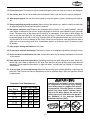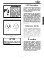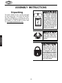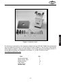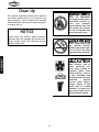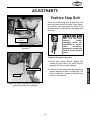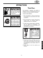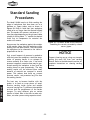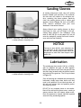
1
MODEL W1686
SPINDLE SANDER
INSTRUCTION MANUAL
Phone: 1-360-734-3482 • On-Line Technical Support: [email protected]
COPYRIGHT © AUGUST, 2002 BY WOODSTOCK INTERNATIONAL, INC.
WARNING: NO PORTION OF THIS MANUAL MAY BE REPRODUCED IN ANY SHAPE OR FORM WITHOUT
THE WRITTEN APPROVAL OF WOODSTOCK INTERNATIONAL, INC.
Printed in Taiwan
ONLINE MANUAL DISCLAIMER
THE INFORMATION IN THIS MANUAL REPRESENTS THE CONFIGURATION OF THE MACHINE AS IT IS CURRENTLY BEING SHIPPED. THE MACHINE CONFIGURATION CAN CHANGE AS PRODUCT IMPROVEMENTS ARE INCORPORATED. IF YOU OWN AN EARLIER VERSION OF THE MACHINE, THIS MANUAL MAY NOT
EXACTLY DEPICT YOUR MACHINE . CONTACT CUSTOMER SERVICE IF YOU HAVE ANY QUESTIONS ABOUT DIFFERENCES. PREVIOUS VERSIONS ARE NOT
AVAILABLE ONLINE.
WARNING
Some dust created by power sanding, sawing, grinding, drilling, and other construction activities contains chemicals known to the State of California to
cause cancer, birth defects or other reproductive
harm. Some examples of these chemicals are:
• Lead from lead-based paints.
• Crystalline silica from bricks, cement, and
other masonry products.
• Arsenic and chromium from chemically
treated lumber.
Your risk from these exposures varies, depending on
how often you do this type of work. To reduce your
exposure to these chemicals: work in a well ventilated area, and work with approved safety equipment, such as those dust masks that are specially
designed to filter out microscopic particles.
1.
3.
6.
MAINTENANCE
USE THE QUICK GUIDE PAGE LABELS TO SEARCH OUT INFORMATION FAST!
OPERATIONS
7.
ADJUSTMENTS
5.
ASSEMBLY
4.
ELECTRICAL
3.
SAFETY
2.
PAGE
INTRODUCTION ..............................................................................................2
About Your New Sander ............................................................................2
Woodstock Service And Support ..................................................................2
Warranty And Returns ..............................................................................3
Machine Specifications ..............................................................................3
SAFETY ......................................................................................................4
Standard Safety Instructions ....................................................................4-5
Additional Safety Instructions For Sander ......................................................6
Avoiding Potential Injuries ........................................................................7
ELECTRICAL REQUIREMENTS ............................................................................8
110V Operation ......................................................................................8
Extension Cords ......................................................................................8
Grounding ..............................................................................................8
220V Operation ......................................................................................9
Extension Cords ......................................................................................9
Grounding ..............................................................................................9
ASSEMBLY INSTRUCTIONS ..............................................................................10
Unpacking ........................................................................................10-11
Clean Up ..............................................................................................12
General ................................................................................................13
Table/Trunnion ......................................................................................13
Dust Port ..............................................................................................14
Sanding Spindle ................................................................................15-16
Sanding Sleeve ......................................................................................17
Table Insert ..........................................................................................18
ADJUSTMENTS ............................................................................................19
Positive Stop Bolt ................................................................................19-20
OPERATIONS ..............................................................................................21
Test Run ..............................................................................................21
Standard Sanding Procedures ....................................................................22
Bevel Sanding Procedures ........................................................................23
MAINTENANCE ............................................................................................24
General ................................................................................................24
Cleaning ..............................................................................................24
Table And Base ......................................................................................24
Sanding Sleeves ......................................................................................25
Lubrication ..........................................................................................25
CLOSURE ..................................................................................................26
Wiring Diagram ......................................................................................27
Parts Breakdown And Parts List ............................................................28-31
Notes ..................................................................................................32
Warranty ..............................................................................................33
INTRODUCTION
TABLE OF CONTENTS
INTRODUCTION
INTRODUCTION
About Your New Sander
Your new SHOP FOX® W1686 has been specially designed to provide many years of trouble-free service.
Close attention to detail, ruggedly built parts and a rigid quality control program assure safe and reliable operation.
The Model W1686 is capable of a wide variety of sanding operations. Features include a 1 HP 110/220V
single-phase 1725 RPM motor, a 72 strokes per minute (SPM) oscillation rate, a precision-ground cast iron
table that measures 27 9⁄16" x 27 9⁄16", a 45˚ front and 20˚ back table tilting capacity, a 4" dust port, and
large assortment of rubber sanding spindles. Whether used in a professional setting or a home shop, the
Model W1686 will be well appreciated as a fine woodworking machine.
Woodstock International, Inc. is committed to customer satisfaction in providing this manual. It is our
intent to make sure all the information necessary for safety, ease of assembly, practical use and durability of this product be included.
If you should have any comments regarding this manual, please feel free to contact us at:
Woodstock International, Inc.
Attn: Technical Department
P.O. Box 2309
Bellingham, WA 98227
Woodstock Service And Support
We stand behind our machines! In the event that a defect is found, parts are missing or questions arise
about your machine, please contact Woodstock International Service and Support at 1-360-734-3482 or
send e-mail to: [email protected]. Our knowledgeable staff will help you troubleshoot
problems, send out parts or arrange warranty returns.
-2-
Woodstock International, Inc. warrants all SHOP FOX® machinery to be free of defects from workmanship and materials for a period of 2 years from the date of original purchase by the original owner. This
warranty does not apply to defects due directly or indirectly to misuse, abuse, negligence or accidents,
lack of maintenance, or to repairs or alterations made or specifically authorized by anyone other than
Woodstock International, Inc.
Woodstock International, Inc. will repair or replace, at its expense and at its option, the SHOP FOX®
machine or machine part which in normal use has proven to be defective, provided that the original
owner returns the product prepaid to the SHOP FOX® factory service center or authorized repair facility
designated by our Bellingham, WA office, with proof of their purchase of the product within 2 years, and
provides Woodstock International, Inc. reasonable opportunity to verify the alleged defect through
inspection. If it is determined there is no defect, or that the defect resulted from causes not within the
scope of Woodstock International Inc.'s warranty, then the original owner must bear the cost of storing
and returning the product.
This is Woodstock International, Inc.'s sole written warranty and any and all warranties that may be
implied by law, including any merchantability or fitness, for any particular purpose, are hereby limited
to the duration of this written warranty. We do not warrant that SHOP FOX® machinery complies with
the provisions of any law or acts. In no event shall Woodstock International, Inc.'s liability under this warranty exceed the purchase price paid for the product, and any legal actions brought against Woodstock
International, Inc. shall be tried in the State of Washington, County of Whatcom. We shall in no event
be liable for death, injuries to persons or property or for incidental, contingent, special or consequential damages arising from the use of our products.
Every effort has been made to ensure that all SHOP FOX® machinery meets high quality and durability
standards. We reserve the right to change specifications at any time because of our commitment to continuously improve the quality of our products.
Machine Specifications
Motor Size: ..........................................................1 HP 110/220V Single-Phase
Motor Speed ..............................................................................1725 RPM
Amps ..............................................................................................14/7
Spindle Size....1⁄4" x 5", 3⁄8" x 6", 1⁄2" x 6", 5⁄8" x 6", 3⁄4" x 9", 1" x 9", 11⁄2" x 9", 2" x 9", 3" x 9", 4" x 9"
Oscillation Speed ............................................................................72 SPM
Stroke Length....................................................................................11⁄2"
Base Size ....................................................................................16" x 16"
Dust Port ............................................................................................4"
Table ..............................................Precision-Ground Cast Iron 279⁄16" x 279⁄16"
Stand ......................................................Cabinet-Style, Powder Coated Paint
Power Transfer ........................................................................Direct Drive
Bearings ......................................Sealed & Permanently Lubricated Ball Bearings
Switch ............................................Paddle ON/OFF Switch, w/ Safety Lock Key
Shipping Weight ............................................................................287 lbs.
-3-
INTRODUCTION
INTRODUCTION
Warranty And Returns
SAFETY
SAFETY
READ MANUAL BEFORE OPERATING MACHINE.
FAILURE TO FOLLOW INSTRUCTIONS BELOW WILL
RESULT IN PERSONAL INJURY.
Indicates an imminently hazardous situation which, if not avoided, WILL
result in death or serious injury.
Indicates a potentially hazardous situation which, if not avoided, COULD
result in death or serious injury.
Indicates a potentially hazardous situation which, if not avoided, MAY
result in minor or moderate injury. It may also be used to alert against
unsafe practices.
NOTICE
This symbol is used to alert the user to useful information about proper
operation of the equipment.
Standard Safety Instructions
1. Thoroughly read the instruction manual before operating your machine. Learn the applications,
limitations and potential hazards of this machine. Keep manual in a safe, convenient place for future
reference.
2. Keep work area clean and well lighted. Clutter and inadequate lighting invite potential hazards.
3. Ground all tools. If a machine is equipped with a three-prong plug, it must be plugged into a threehole grounded electrical receptacle or grounded extension cord. If using an adapter to aid in accommodating a two-hole receptacle, ground using a screw to a known ground.
4. Wear eye protection at all times. Use safety glasses with side shields or safety goggles that meet
the national safety standards, while operating this machine.
5. Avoid dangerous environments. Do not operate this machine in wet or open flame environments.
Airborne dust particles could cause an explosion and severe fire hazard.
6. Ensure all guards are securely in place and in working condition.
7. Make sure switch is in the OFF position before connecting power to machine.
8. Keep work area clean, free of clutter, grease, etc.
9. Keep children and visitors away. Visitors should be kept at a safe distance while operating unit.
10. Childproof workshop with padlocks, master switches or by removing starter keys.
11. Disconnect machine when cleaning, adjusting or servicing.
-4-
12. Do not force tool. The machine will do a safer and better job at the rate for which it was designed.
13. Use correct tool. Do not force machine or attachment to do a job for which it was not designed.
15. Remove adjusting keys and wrenches. Before turning the machine on, make it a habit to check that
all adjusting keys and wrenches have been removed.
16. Use proper extension cord. Examine the extension cord to ensure it is in good condition. Use the
chart below to determine the correct length and gauge of extension cord needed for your particular
needs. The amp rating of the motor can be found on its nameplate. If the motor is dual voltage, be
sure to use the amp rating for the voltage you will be using. If you use an extension cord with an
undersized gauge or one that is too long, excessive heat will be generated within the circuit increasing the chance of a fire or damage to the circuit. Never use an extension cord that does not have a
ground pin and connected ground wire. Immediately replace an extension cord if it shows any signs
of damage.
17. Keep proper footing and balance at all times.
18. Do not leave machine unattended. Wait until it comes to a complete stop before leaving the area.
19. Perform machine maintenance and care. Follow lubrication and accessory attachment instructions
in the manual.
20. Keep machine away from open flame. Operating machines near pilot lights and/or open flames creates a high risk if dust is dispersed in the area. Dust particles and an ignition source may cause an
explosion. Do not operate the machine in high-risk areas, including but not limited to, those mentioned above.
21. If at any time you are experiencing difficulties performing the intended operation, stop using the
machine! Then contact our service department or ask a qualified expert how the operation should
be performed.
Operating this equipment has the potential
for flying debris to cause eye injury. Always
wear safety glasses or goggles when operating equipment. Everyday glasses or reading
glasses only have impact resistant lenses,
they are not safety glasses. Be certain the
safety glasses you wear meet the appropriate standards of the American National
Standards Institute (ANSI).
Extension Cord Requirements
Amp Rating
0-6
7-10
11-12
13-16
17-20
21-30
Length
25ft
#18
#18
#16
#14
#12
#10
And Gauge
50ft 100ft
#16 #16
#16 #14
#16 #14
#12 #12
#12 #10
#10
No
-5-
SAFETY
14. Wear proper apparel. Do not wear loose clothing, neck ties, gloves, jewelry, keep long hair tied up,
etc.
SAFETY
Additional Safety Instructions For Sanders
MODEL W1686
SPINDLE SANDER
INSTRUCTION MANUAL
Phone: 1-360-734-3482 • On-Line Technical Support: [email protected]
COPYRIGHT © AUGUST, 2002 BY WOODSTOCK INTERNATIONAL, INC.
WARNING: NO PORTION OF THIS MANUAL MAY BE REPRODUCED IN ANY SHAPE OR FORM WITHOUT
THE WRITTEN APPROVAL OF WOODSTOCK INTERNATIONAL, INC.
Printed in Taiwan
Use this and other machinery with caution
and respect and always consider safety
first, as it applies to your individual working
conditions. Remember, no list of safety
guidelines can be complete and every shop
environment is different. Failure to follow
guidelines can result in serious personal
injury, damage to equipment and/or poor
work results.
Read and understand this
entire instruction manual
before using this machine.
Serious personal injury may
occur if safety and operational information is not
understood and followed.
Do not risk your safety by
not reading!
1. Spindle Rotation: Always brace workpiece against the rotation of the sanding spindle.
2. Finger Safety: Always keep fingertips away from the moving spindle.
3. Sanding Rate: Always use light pressure when holding the workpiece against the sanding spindle.
5. Personal Safety Equipment: Always wear ANSI-approved safety glasses, ear plugs and dust mask.
6. Sand Safe Stock: Always sand stock that is clean and free of defects.
7. Sanding Sleeves: Always replace sanding sleeves that are damaged or worn out.
8. Develop Good Habits: Always follow directions and safety warning to develop good habits.
9. Air Quality: Make sure there is good ventilation and a constant source of fresh air near the operating sander and always use a dust collector.
10.Allergic Reactions: The saw dust from some species of wood can be toxic to some people. Be sure
to research the dangers of the specific species of wood you are sanding.
-6-
Avoiding Potential Injuries
SAFETY
Figure A. Never sand a workpiece while holding it
off the table surface.
Figure B. Never touch a moving spindle.
-7-
ELECTRICAL REQUIREMENTS
ELECTRICAL
110V Operation
The SHOP FOX® W1686 is prewired for 110 volts.
The motor supplied with your new machine is
rated at 1 HP and will draw approximately 14
amps. When choosing a circuit for this machine,
consider using one with a 15 amp circuit breaker or fuse. Keep in mind that a circuit being used
by other machines or tools at the same time will
add to the electrical load being applied by the
machine. Add up the load ratings of all machines
on the circuit. If this number exceeds the rating
of the circuit wires or circuit breaker/fuse, use
a different circuit.
Any electrical outlet and circuit that you plug your
machine into must be
grounded. Never remove
the grounding pin from any
plug and always make sure
all wiring to the machine is
grounded before operating.
Serious injury make occur if
this warning is ignored!
Verify that your current household circuit wiring
is capable of handling the current load of this
machine. A qualified electrician may need to
install a new circuit with wiring capable of handling a 14 amperage draw. Do not attempt to
modify an existing circuit by replacing the circuit breaker with one rated for a higher amperage.
Extension Cords
When it is necessary to use an extension cord,
use the following guidelines:
• Use cords rated for Hard Service
• Never exceed a length of 100 feet
• Use cords with 14 ga. wire or bigger
(12 ga., 10 ga., etc.)
• Ensure cord has a ground wire and pin
• Do not use cords in need of repair
Figure 1. Typical 110V 3-prong plug and
receptacle.
Grounding
This machine must be grounded! The electrical
plug supplied with the Model W1686 comes with
a grounding pin as shown in Figure 1. Do not
remove it. If your receptacle does not accommodate a ground pin, have it replaced by a qualified electrician or have an appropriate adapter
installed. Please note: when using an adapter,
the adapter must be grounded. An adapter with
a grounding wire does not guarantee the
machine will be grounded. A ground source must
be verified.
-8-
220V Operation
The SHOP FOX® W1686 can also be operated at
220 volts. To do this, consult with the wiring
diagram in the back of this manual. Also, you
will need a NEMA-style 6-15 plug and receptacle as shown in Figure 2.
Any electrical outlet and circuit that you plug your
machine into must be
grounded. Never remove
the grounding pin from any
plug and always make sure
all wiring to the machine is
grounded before operating.
Serious injury make occur if
this warning is ignored!
Extension Cords
6-15P
We do not recommend using an extension cord
with 220V equipment. Instead, arrange the
placement of your machinery and installed
wiring to eliminate the need for extension
cords. If you must use an extension cord, make
sure it is rated Hard Service (grade S) or better.
The extension cord must always contain a
ground wire and plug pin. Always repair or
replace extension cords when they become
worn or damaged.
6-15R
Figure 2. NEMA-style 6-15 plug and
receptacle.
NOTICE
Grounding
Never replace the circuit breaker with one
rated at a higher amperage or damage to the
circuit may occur.
This machine must be grounded! The electrical
cord supplied with the Model W1686 does not
come with a 220 volt plug. Use a plug with a
ground pin as shown in Figure 2. If your receptacle does not accommodate a ground pin, have
it replaced by a qualified electrician or have an
appropriate adapter installed and grounded
properly. An adapter with a grounding wire
does not guarantee the machine will be grounded. A ground source must be verified.
-9-
ELECTRICAL
The motor supplied with your new machine is
rated at 1 HP and will draw approximately 7
amps during 220 volt operation. When choosing
a circuit for this machine, consider using one
with a 10 amp double-pole circuit breaker or
fuse. Keep in mind that a circuit being used by
other machines or tools at the same time will
add to the total load being applied to the circuit. Add up the load ratings of all machines on
the circuit. If this number exceeds the rating of
the circuit wires or circuit breaker/fuse, use a
different circuit.
ASSEMBLY INSTRUCTIONS
Unpacking
The Model W1686 has been carefully packaged
for safe transporting. If you notice the machine
has been damaged or is missing any parts,
please contact Woodstock International Service
and Support at 1-360-734-3482 or send e-mail
to: [email protected].
MODEL W1686
SPINDLE SANDER
INSTRUCTION MANUAL
Phone: 1-360-734-3482 • On-Line Technical Support: [email protected]
COPYRIGHT © AUGUST, 2002 BY WOODSTOCK INTERNATIONAL, INC.
WARNING: NO PORTION OF THIS MANUAL MAY BE REPRODUCED IN ANY SHAPE OR FORM WITHOUT
THE WRITTEN APPROVAL OF WOODSTOCK INTERNATIONAL, INC.
Printed in Taiwan
It is absolutely critical that
you read and understand
this entire instruction
manual before performing
any operations with your
machine. Serious personal
injury may occur if safety
and operational information is not understood and
followed. Do not risk your
safety by not reading!
ASSEMBLY
The W1686 represents a
heavy load. Seek assistance before moving into
position.
Always make sure that all
entrances to your shop are
locked or that machines
are equipped with safety
lock-out devices to protect
curious children or visitors
from serious injury. Never
allow unsupervised people
in your shop who have not
been fully trained!
-10-
ASSEMBLY
Figure 3. Component layout.
The following is a description of the components shipped with the SHOP FOX® W1688. We recommended
that the components be laid out in a similar fashion to those in Figure 3. This will help in identification
before beginning assembly. Should any parts appear to be missing, examine the packaging carefully. If
any key parts are missing, call Woodstock International, Inc. at 360-734-3482 or e-mail:
[email protected].
Item
Qty.
Spindle Sander Base
Spindle Sander Table
Sanding Spindles
Table Inserts
Spindle Wrench
Hardware Bag
1
1
10
4
1
1
-11-
Clean Up
The exposed, unpainted surfaces of the machine
have been coated with an oil to prevent rust
during shipment. This oil needs to be removed
before operation. Use a solvent based degreaser
to remove the oil.
Never use flammables
such as gas or other petroleum-based solvents to
clean
your
machine.
These products have low
flash points and present
the risk of explosion and
severe personal injury!
NOTICE
Avoid using any chlorine based solutions
because they will damage the painted surfaces. Always follow the instruction of the
product being used.
ASSEMBLY
Never smoke while using
any cleaning solvents.
Smoking may cause explosion or risk of fire when
exposed to these products!
Most solvents used to
clean machinery are
toxic when inhaled or
ingested. When using
these products, work in
a well ventilated area
and keep away from any
potential
ignition
sources (pilot lights).
Always dispose of any
waste rags in a sealed
container to make sure
they do not cause fire or
environmental hazards.
-12-
General
The main components of the SHOP FOX® W1686
are assembled at the factory; however, some
assembly is required.
Loose clothing and long
hair must be secured
and kept away from
moving parts.
Table/Trunnion
Make sure that your
machine
remains
unplugged during any
adjustments or maintenance
procedures.
Ignoring this warning may
result in serious personal
injury!
Get assistance before lifting the table/trunnion
assembly. Personal injury
can occur if assistance is
not used when lifting the
table/trunnion assembly.
To attach the table/trunnion assembly:
2. Align the mounting holes in the trunnions
with the mounting holes in the sander base.
3. Using the (4) 3⁄8"-16 x 11⁄4" hex bolts and (4)
3
⁄8" lock washers, secure the table/trunnion
assembly to the sander base as shown in
Figure 4.
NOTICE
DO NOT overtighten the mounting bolts as
this may strip the threads from the cast iron
components.
Figure 4. Secure the table/trunnion assembly
to the sander base using the supplied hex
bolts and lock washers.
-13-
ASSEMBLY
1. With the assistance of a helper, carefully lift
the table/trunnion assembly onto the top of
the sander base.
Safety
glasses
are
absolutely required during assembly. Serious
injury may occur if this
warning is ignored!
Dust Port
Connect a dust collector to the 4" dust port on
the back of the sander as shown in Figure 5.
If you do not have a dust collection system, you
can buy adapters to allow hook-up to a shop vacuum. Although not as adequate as a dust collector, a shop vacuum will help reduce the amount
of uncontained dust and debris.
ASSEMBLY
Figure 5. Attach a dust collection system to
the 4" dust port to reduce the amount of
uncontained dust.
Failure to use a dust collection system can result
in short and long-term respiratory illness. DO NOT
operate the Model W1686
without an adequate dust
collection system. This
machine creates substantial amounts of wood dust
while in operation.
-14-
Sanding Spindle
The Model W1686 is supplied with ten rubber
sanding spindles. Use the larger diameter spindles for sanding large sweeping curves and the
smaller spindles for sanding more intricate
curves.
When not in use, the spindles are stored on
racks located on each side of the machine base
as shown in Figure 6. Each spindle is secured to
the rack with a hex nut.
To mount the spindle for sanding:
Figure 6. Spindle storage racks are located on
the sides of the machine.
1. Determine the spindle size needed.
2. Lightly lubricate the threads shown in Figure
7 with a light lubricant.
NOTICE
DO NOT tighten the sanding spindle down
with a wrench! The sanding action will further tighten the spindle to the sander.
Figure 7. Lubricate the spindle shaft threads.
Figure 8. Use only hand pressure when tightening the spindle into the sander.
-15-
ASSEMBLY
3. Insert the threaded end of the spindle shaft
into the spindle mounting hole and screw it
down by hand as shown in Figure 8. The spindle is now mounted and ready for action.
To remove the spindle:
1. Use an adjustable wrench to hold the jam
nuts stationary as shown in Figure 9.
2. While holding the jam nuts stationary, use
the supplied wrench to loosen the spindle
retainer nut at the base of the spindle as
shown in Figure 10.
3. Remove the spindle and return it to the storage rack.
ASSEMBLY
Figure 9. (Table removed for clarity only) Use
an adjustable wrench to hold the jam nuts
stationary during spindle removal.
Figure 10. (Table removed for clarity only) Use
the supplied spindle wrench to loosen the
retainer nut on the base of the spindle while
holding the adjustable wrench.
-16-
Sanding Sleeve
The Model W1686 is supplied with 10 sanding
sleeves. Use coarse (low #) grits for fast material removal and a rough finish. Use fine (high #)
grits for slower material removal and a smoother
finish. When changing from a coarse sleeve to a
finer sleeve on a particular sanding project,
never increase the grit number by intervals of
more than 50.
To change the sanding sleeve:
1. Loosen the hex nut located on the top of the
spindle as shown in Figure 11. The hex nut
and flange disk DO NOT need to be removed.
Figure 11. To remove the sanding sleeve from
the spindle, loosen the hex nut on the top
of the spindle.
NOTICE
2. Slide the sanding sleeve from the spindle.
3. Reverse the above steps to install a sanding
sleeve.
Figure 12. The four smallest spindles have
small setscrews located in the retainer nut.
Loosen these setscrews to remove the
sanding sleeve.
NOTICE
Monitor the wear on the sanding sleeves.
Often times the upper portion of the sanding
sleeve gets very little use. If this is the case,
flip the sanding sleeve over and re-install.
This allows maximum use of the sleeve. Worn
sanding sleeves will not efficiently remove
material and can burn the wood.
-17-
ASSEMBLY
Spindle sizes 5⁄8" and smaller have setscrews
located in the retainer nut. These setscrews
hold the sanding sleeve onto the spindle as
shown in Figure 12.
Table Insert
The Model W1686 is supplied with three different sized table inserts. The inserts are designed
to reduce the gap between the spindle and the
table opening. The hole in each insert is oblong
to allow clearance when the table is in the tilted position.
NOTICE
Always use the table insert with the smallest
opening that still allows at least 1⁄8" clearance around the spindle.
Figure 13. The table insert should clear the
spindle by at least 1⁄8" on all sides. Pins on
the underside of the insert ensure correct
positioning in the table.
To install the table insert:
ASSEMBLY
1. Determine which table insert is best for the
particular spindle you are using.
2. Install the insert over the mounted spindle
and into the recessed hole on the table as
shown in Figure 13. The insert is fitted with
pins that allow it to fit into the table in only
one position. This ensures the table insert
will not make contact with the spindle even
when the table is tilted.
3. Adjust the setscrews shown in Figure 14 so
the top of the insert is flush with the table
surface.
Figure 14. Adjust the setscrews to position the
table insert flush with the table surface.
-18-
ADJUSTMENTS
Positive Stop Bolt
There is a positive stop bolt located under the
back right-hand side of the table. When adjusted correctly, this stop allows the table to be
returned square to the spindle with speed and
accuracy.
Retainer Screw
Locking Handle
(1 of 2)
Make sure that your
machine
remains
unplugged during any
adjustments or maintenance
procedures.
Ignoring this warning may
result in serious personal
injury!
Figure 15. Loosen the locking handles on the
trunnions.
To adjust the positive stop bolt:
1. Loosen both locking handles (Figure 15)
located on each side of the table trunnion
assembly and tilt the table forward.
2. Loosen the jam nut and lower the head of the
positive stop bolt as shown in Figure 16. The
positive stop bolt is located on the back left
corner of the machine.
Jam Nut
Figure 16. Loosen the jam nut to allow the
positive stop bolt to be adjusted.
-19-
ADJUSTMENTS
Positive Stop Bolt
2. Using a machinist square, bring the table surface square with the spindle surface as shown
in Figure 17.
3. Move the square to various points around the
table to ensure the table and spindle are
square on all sides.
4. Lock down both handles when you are satisfied with the position of the table.
5. Loosen the retainer screw (Figure 15) that
secures the scale pointer and adjust the scale
pointer to read 0˚. Re-tighten the retainer
screw.
Figure 17. Use a machinist square to adjust
the table square to the spindle.
6. With the table square to the spindle, adjust
the stop bolt until it just touches the underside of the table.
7. Retighten the jam nut to secure the positive
stop bolt.
ADJUSTMENTS
NOTICE
When tilting the table towards the back of
the machine, the positive stop bolt must be
removed completely. Be sure to recalibrate
the positive stop bolt whenever it is moved or
removed.
-20-
OPERATIONS
Test Run
Once assembly is complete, the machine is
ready for a test run. The purpose of a test run is
to identify any unusual noises and vibrations.
Loose clothing and long
hair must be secured
and kept away from
moving parts.
To test run the machine:
1. Turn the machine on. Be sure to have your
finger poised to turn the machine off if there
is a problem.
Always wear a dust mask
and safety glasses in addition to using a dust collector. This machine produces sawdust that may
cause allergic reactions
or respiratory problems.
2. Once the machine is running, listen for any
unusual noises. The machine should run
smoothly with little or no vibrations.
3. If there are any unusual noises or vibrations,
shut the machine off immediately. The
machine should not be run any further until
the problems are corrected.
Make sure that your
machine
remains
unplugged during any
adjustments or maintenance
procedures.
Ignoring this warning may
result in serious personal
injury!
5. Repeat Steps 1-4 until the machine runs
smoothly.
-21-
OPERATIONS
4. Unplug the machine, investigate the source
of the noise or vibration, and correct the
source of the noise or vibration. Do not make
any adjustments to the machine while it is
plugged in.
Standard Sanding
Procedures
The Model W1686 excels at finish sanding the
edges of workpieces that have been cut on a
bandsaw or jigsaw (saber saw) as shown in
Figure 18. Keep in mind that your workpiece
needs to be cut larger than the desired finished
size. The sander will remove a minimum of 1⁄16"
from the edges depending on the grit used. Make
a habit of cutting about 1⁄16" outside the desired
finish line to compensate for material the
sander will remove.
Figure 18. The Model W1686 is best suited for
smoothing the curved cuts made by a bandsaw or jigsaw.
Always move the workpiece against the rotation
of the sander. Never sand the workpiece while
holding it off the table surface. This could cause
the workpiece to be slammed to the table or
propelled into the air.
NOTICE
OPERATIONS
Only a small amount of pressure is needed to
effectively sand the workpiece. Avoid the temptation of pressing harder in an attempt to
remove material at a faster rate. If too much
pressure is applied, excessive heat may be generated causing the workpiece to burn and the
sanding sleeve to wear prematurely. The best
sanding results will be achieved when small
amounts of material are removed in several
passes. This reduces heat build up, ensures
accurate results, and promotes long life from
the sanding sleeves.
Frequent cleaning can go a long way towards
getting the most life from your sanding
sleeves. Refer to the Maintenance section for
complete instructions on cleaning sanding
sleeves.
The best way to become familiar with the
sander is to sand on scrap pieces of wood.
Practice sanding inside curves and outside
curves of varying size. Try different size spindles
and see how the performance of the sander
changes. Try using different grits on various
species of wood. Now is the time to make mistakes, not when you are using expensive stock.
-22-
Bevel Sanding
Procedures
NOTICE
All of the general sanding rules that apply to
standard sanding apply to bevel sanding.
Locking Handle
(1 of 2)
NOTICE
Figure 19. Use the lock handles to secure the
table at the desired angle.
Bevel sanding on a spindle sander is NOT an
exact science. When the table is tilted to
45˚, the actual angle sanded on the edge of
a workpiece will change if the workpiece is
sanded at different positions around the spindle.
Sanding
Spindle
Table
Adjust the table to the desired angle and secure
it into position with the trunnion lock handles as
shown in Figure 19. With the sander turned off,
rotate the spindle by hand to ensure it does not
make contact with the table insert.
Finish Line
Should Be Here
Workpiece
When marking the finish line on your workpiece,
always mark on the outside, or longest, edge of
the bevel as shown in Figure 20. This allows the
finish line to be viewed on the top side of the
workpiece.
Figure 20. Mark the finish line on the longest
edge of the workpiece. This allows the finish
line to be viewed from the top of
the workpiece.
OPERATIONS
-23-
MAINTENANCE
General
Regular periodic maintenance on your Model
W1686 will ensure its optimum performance.
Make a habit of inspecting your machine each
time you use it. Check for the following conditions and repair or replace when necessary.
Loose clothing and long
hair must be secured
and kept away from
moving parts.
1. Loose mounting bolts.
2. Worn switch.
Make sure that your
machine
remains
unplugged during any
adjustments or maintenance
procedures.
Ignoring this warning may
result in serious personal
injury!
3. Worn or damaged cords and plugs.
4. Damaged sanding sleeve.
5. Any other condition that could hamper the
safe operation of this machine.
Cleaning
Because sanders produce more saw dust than
most other woodworking machines, extra care
must be taken to vacuum off areas that accumulate dust. If left to build up, the saw dust will
work its way into the motor, bearings, and all
other parts of the machine. Eventually the saw
dust will begin to cause damage to the internal
workings of the sander.
Safety
glasses
are
absolutely required during maintenance. Serious
injury may occur if this
warning is ignored!
If any part of the sander becomes difficult to
operate, it is most likely caused by an accumulation of saw dust. Immediately investigate the
area and remove the saw dust.
Table And Base
MAINTENANCE
Tables can be kept rust-free with regular applications of products like SLIPIT® . For long term
storage you may want to consider products like
Boeshield® T-9 .
-24-
Sanding Sleeves
As sanding sleeves are used, they will quickly
become "loaded" with saw dust. If not removed,
this saw dust will harden on the abrasive surface, rendering the sleeve useless. Routinely
clean the sanding sleeves with a rubber gum
abrasive cleaner (Figure 21) such as the PROSTIK® cleaners available from your local
Woodstock International dealer.
Always discard worn sanding sleeves. As abrasives begin to wear, grit will begin to fall off,
causing deep gouges in the workpiece. Glue
used to hold the grit to the paper will rub off
onto the workpiece causing burns and interference with the final finishing.
Figure 21. Routinely clean sanding sleeves with
a rubber abrasive cleaning stick.
NOTICE
Contrary to some beliefs, worn abrasives are
not equivalent to the next finer grit abrasive.
Discard worn sanding sleeves and avoid the
temptation to sand with them beyond their
usable life.
Lubrication
The spindle gear box contains 2.8 Qts. of 90 Wt.
gear oil. Replace the gear oil after approximately 1000 hours of use. Drain the gear oil from
the drain plug located inside the sander base at
the bottom of the gear box. The fill cap is shown
in Figure 21.
Figure 21. Routinely clean sanding sleeves with
a rubber abrasive cleaning stick.
Since all bearings are shielded and permanently
lubricated, simply leave them alone until they
need to be replaced. Do not lubricate them, as
this will only attract dust and possible premature bearing failure.
-25-
MAINTENANCE
DO NOT oil any exposed areas on the sander.
Dust will be attracted to these areas, creating a
gummy mixture that will hamper proper movement of components. Instead, lubricate exposed
areas with dry powdered graphite.
CLOSURE
We recommend you keep this manual for complete information regarding Woodstock
International, Inc.’s warranty and return policy.
Should a problem arise, we recommend that you
keep your proof of purchase with your manual.
If you need additional technical information
relating to this machine, or if you need general
assistance or replacement parts, please contact
the Service Department at 1-360-734-3482 or email: [email protected].
The following pages contain parts diagrams/lists
and a warranty card for your SHOP FOX® Model
W1686.
If you need parts or help in assembling your
machine, or if you need operational information, we encourage you to call our Service
Department. Our trained service technicians will
be glad to help you.
If you have comments dealing specifically with
this manual, please write to us using the address
in the General Information. The specifications,
drawings, and photographs illustrated in this
manual represent the Model W1686 as supplied
when the manual was prepared. However, due
to Woodstock International, Inc.’s policy of continuous improvement, changes may be made at
any time with no obligation on the part of
Woodstock International, Inc. Whenever possible, though, we send manual updates to all owners of a particular tool or machine that have registered their purchase with our warranty card.
Should you receive one, add the new information to this manual and keep it for reference.
Additional information sources are necessary to
realize the full potential of this machine. Trade
journals, woodworking magazines, and your
local library are good places to start.
The Model W1686 is specifically designed for
sanding operations. DO NOT MODIFY AND/OR
USE THIS MACHINE FOR ANY OTHER PURPOSE.
MODIFICATIONS OR IMPROPER USE OF THIS
TOOL WILL VOID THE WARRANTY. If you are
confused about any aspect of this machine, DO
NOT use it until all your questions have been
answered.
We have included some important safety measures that are essential to the operation of the
machine. While most safety measures are generally universal, we remind you that each workshop is different and safety rules should be considered as they apply to your specific situation.
Operating this equipment has the potential
for flying debris to cause eye injury. Always
wear safety glasses or goggles when operating equipment. Everyday glasses or reading
glasses only have impact resistant lenses,
they are not safety glasses. Be certain the
safety glasses you wear meet the appropriate standards of the American National
Standards Institute (ANSI).
As with all power tools, there is danger
associated with the Model W1686. Use the
tool with respect and caution to lessen the
possibility of mechanical damage or operator injury. If normal safety precautions are
overlooked or ignored, injury to the operator or others in the area is likely.
-26-
W1686 Spindle Sander
110 VOLT
Disconnect power from machine
before performing any electrical
service. Failure to do this will
result in a shock hazard leading
to injury or death.
MOTOR WIRES
BLACK
YELLOW
WHITE
RED
NOTE: THE WIRES FROM THE
POWER SUPPLY, BESIDES THE
GREEN GROUND WIRE, ARE
INTERCHANGABLE, THEREFORE
COLORS ARE NOT SPECIFIED.
GREEN (GROUND)
TO 110 VOLT
POWER SUPPLY
220VOLT
MOTOR WIRES
BLACK
RED
YELLOW
WHITE
GREEN (GROUND)
TO 220 VOLT
POWER SUPPLY
94
93
11
94
1
94
12
93
93
83
6
122
92
7
10
82
13
91
76
17
95
84
14
15
81
92
16
90
92
80
85
72
98
91
92
99
21
75
91
24 92
99
90
92
92
14
16
15
102
95
92
117
118
64
79
96
113
114
18
99
70
97
107
19
5
71
76
77
78
2
35
45
20
99
92
103
123
FAI
LUR
SER E
IOU TO FO
S PER LLO
1.
UA
SO W THE
L BE
NA
L INJ SE
FO
2.
RE
UR WARN
STA
TIO
Y:
ING
N.
RTI
S WIL
NG
3.
L RE
MA
DU
CH
SU
ST
INE READ
LT
.
IN
4. MASK
AN
D UN
OR
GR
ALW
DE
RE
OU
RS
SPI
AY
TAN
5. NDED
RA
S WE
TO
D MA
OU
ING
R.
AR
TLE
ALW
N,
EYE
T ON
AY
UP GLOV
PR
S WE
OR ES
LY.
OT
BU OR
EC
AR
6.
PLU
TTO JEW
AN
G PO
EN
N LO ELR
AP
CE
PR
WE
NG Y.
OV
OR OF
R CO
SLE ROLL DO
ED
IF DRUG
NO
RD
EVE
7. EXCESS
T WE
S OR
INT
S,
AN
O
AR
FLA
IVE ALC
D TIE
LO
LY
T,
OS
TIR OHOL
8. LEVEL
DO BACK
E CLO
ED
,
NO
.
GR
AN
THT US LONG
OU
D AD
ND
E UN HA
JUS
.
DE IR.
TED
R THE
ON
CO
LY
RR
INF
OP
EC
LUER
TLY
ATE
MA
MA
KE
CH
SU
INE
RE
MA
ON
CH
INE
IS
SET
UP
WA
RN
ING
.
126
125
30
33
111
W
Mo 1686
tor
Sp
Sw : 1
in
itc HP
Sp h: 110 , 110 dle
ind
Sa
nd
Os le Sp V (22/220V
cill
er
,
Str ation eed: 0V Op Prewir
ok
172
Ta e Le Speed 5 tiona ed 110
RP l)
ble ng
V
Ge Tilt: th: : 72 M
ar
11
SP
M
We Oil Wt45˚ Fro/2''
igh
t: 287./Cap nt, 20˚
lbs acity: Back
.
90
Wt
. / 2.8
Qts
124
34
33
111
31
22
30
99
99
32
28
86
110
101
100
99
112
27
31
8
105
108
23
29
28
104
107
25
106
26
109
120
59
44
99
3
4
87
120
44
46
42
43
120
116
89
115
120
99
58
88
119
40
41
120
73
38
39
120
36
120
37
116
44
115
120
63
69
121
119
44
120
62
121
68
74
44
120
61
121
67
44
120
60
121
67
REF
PART #
001
002
003
004
005
006
007
008
010
011
012
013
014
015
016
017
018
019
020
021
022
023
024
025
026
027
028
029
XPN07
X1686002
XPW02
X1686004
X1686005
X1686006
X1686007
XPK22M
X1686010
X1686011
X1686012
X1686013
X1686014
X1686015
X1686016
X1686017
X1686018
X1686019
X1686020
X1686021
X1686022
X1686023
X1686024
X1686025
X1686026
X1686027
X1686028
X1686029
DESCRIPTION
HEX NUT 10-24
SPECIAL CAP SCRW 5/16"-18 x 1"
FLAT WASHER 3/8"
SPACER
NAME PLATE
INSERT 4 1/8"
DUST COVER
KEY 5 x 5 x 24mm
MOUNTING PLATE
TABLE
INSERT, 13/4" x 2"
INSERT, 2" x 33/8"
BRACKET
TRUNNION
INNER TRUNNION
DUST HOOD
HOUSING CASTING
DIPSTICK
SPINDLE CASTING
COVER
SPINDLE
KEY 5 X 5 X 20MM
SPINDLE RETAINER
SPINDLE COLLAR
WORM
MOUNTING BRACKET
BEARING BLOCK
WORM GEAR 24T
REF
PART #
DESCRIPTION
030
031
032
033
034
035
036
037
038
039
040
041
042
043
044
045
046
058
059
060
061
062
063
064
065
067
068
069
X1686030
X1686031
X1686032
X1686033
X1686034
X1686035
X1686036
X1686037
X1686038
X1686039
X1686040
X1686041
X1686042
X1686043
X1686044
X1686045
X1686046
X1686058
X1686059
X1686060
X1686061
X1686062
X1686063
X1686064
X1686065
X1686067
X1686068
X1686069
CONNECTING ROD
WRIST PIN
DRIVE SHAFT
HUB
CENTER BLOCK
CASE N/S
ARBOR
SPINDLE 1/4"
SPINDLE 3/8"
RETAINER
SPINDLE 1/2"
RETAINER
SPINDLE 5/8"
RETAINER
RETAINER
GUIDE SHAFT
SPINDLE 3/4"
RUBBER GROMMET
SPINDLE 1"
SPINDLE 11/2"
SPINDLE 2"
SPINDLE 3"
SPINDLE 4"
HEX BOLT 3/8" - 16 x 61/2"
GREASE FITTING
FLANGE
FLANGE
FLANGE
REF
PART #
070
071
072
073
074
075
076
077
078
079
080
081
082
083
084
085
086
087
088
089
090
091
092
093
094
095
096
X1686070
X1686071
X1686072
X1686073
X1686074
X1686075
X1686076
X1686077
X1686078
X1686079
X1686080
X1686081
X1686082
X1686083
X1686084
X1686085
X1686086
X1686087
X1686088
XPAW02M
XPB24
XPB18
XPLW04
XPSS07
XPRP42M
XPW02
XPN02
DESCRIPTION
POINTER
POINTER MOUNT
CABINET
SPINDLE HOLDER
SPINDLE HOLDER
DOOR
LOCK HANDLE
SCALE
RIVET
OIL BREATHER
KNOB 1⁄4" - 20 X 1"
GASKET
SWITCH
CORD, SWITCH TO MOTOR
POWER CORD
STRAIN RELIEF
MOTOR 1 HP
WRENCH 35MM
SPINDLE WRENCH
ALLEN® WRENCH 2 MM
HEX BOLT 3/8" - 16 x 11/4"
HEX BOLT 3/8" - 16 x 1"
LOCK WASHER 3/8"
SETSCREW 1/4" - 20 x 1/2"
ROLL PIN 3 x 20mm
FLAT WASHER 3/8"
HEX NUT 5/16" - 18
REF
PART #
097
098
099
100
101
102
103
104
105
106
107
108
109
110
111
112
113
114
115
116
117
118
119
120
121
122
123
124
125
126
XPSB38
XPB16
XPN08
XPSB03
XPLW01
XPSB16
XPSB16
XP6206
X1686105
XPR38M
XP6205
XPSB39
XPRP05M
XPK12M
XPSS08
X1686112
XPN04
XPLW06
XPB19
XPLW02
XPB03
X1686118
XPN13
XPSS29
XPN03
XPS03
X1686123
XLABEL01
X1686125
X1686126
DESCRIPTION
CAP SCREW 10 - 32 x 3/8"
HEX BOLT 3/8" - 16 x 1 1/2"
HEX NUT 3/8" - 16
CAP SCREW 5/16" - 18 x 1"
LOCK WASHER 5/16"
CAP SCREW 3/8" - 16 x 3/4"
CAP SCREW 3/8" - 16 x 3/4"
BEARING 6206 - 2RS
SEAL 30 - 62 - 8
SNAP RING 62mm
BEARING 6205 - 2RS
CAP SCREW 5 - 40 x 1/2"
ROLL PIN 5 x 30mm
KEY 5 x 5 x 30mm
SETSCREW 5/16" - 18 x 1/2"
DRAIN PLUG
HEX NUT 5/8" - 11
LOCK WASHER 5/8"
HEX BOLT 1/4" - 20 x 1/2"
LOCK WASHER 1/4"
HEX BOLT 5/16" - 18 x 1"
5
/16" FENDER WASHER
HEX NUT 1/2" - 13
SETSCREW 10 - 24 x 1/4"
HEX NUT 3/4" - 16
PHLP HD SCRW 10 - 24 x 1"
MACHINE ID/WARNING
SAFETY GLASSES 2" X 3"
READ MANUAL WARNING
ELECTRICITY WARNING
NOTES
NOTES
NOTES
WARRANTY CARD
Name __________________________________________________________________________________________
Street __________________________________________________________________________________________
City ____________________________________________________________________State________Zip_________
Phone Number_______________________E-Mail_________________________________FAX___________________
MODEL #______________________________ Serial #___________________________________________________
The following information is given on a voluntary basis and is strictly confidential.
1.
Where did you purchase your SHOP FOX® machine?
_________________________________________________________
2.
How did you first learn about us?
___Advertisement
___Mail order Catalog
___World Wide Web Site
10.
___Air Compressor
___Panel Saw
___Band Saw
___Planer
___Drill Press
___Power Feeder
___Drum Sander
___Radial Arm Saw
___Dust Collector
___Shaper
___Horizontal Boring Machine
___Spindle Sander
___Jointer
___Table Saw
___Lathe
___Vacuum Veneer Press
___Mortiser
___Wide Belt Sander
___Other__________________________________________________
___Friend
___Local Store
___Other__________________________________________________
CUT ALONG DOTTED LINE
3.
Which of the following magazines do you subscribe to.
___American Woodworker
___Today’s Homeowner
___Cabinetmaker
___Wood
___Family Handyman
___Wooden Boat
___Fine Homebuilding
___Woodshop News
___Fine Woodworking
___Woodsmith
___Home Handyman
___Woodwork
___Journal of Light Construction
___Woodworker
___Old House Journal
___Woodworker’s Journal
___Popular Mechanics
___Workbench
___Popular Science
___American How-To
___Popular Woodworking
___Other__________________________________________________
4.
11.
12.
6.
14.
What new accessories would you like Woodstock International to carry?
_________________________________________________________
_________________________________________________________
15.
Do you think your purchase represents good value?
___Yes
16.
___Advanced
___Master Craftsman
How many SHOP FOX® machines do you own? _____________
17.
___No
Would you recommend SHOP FOX® products to a friend?
___Yes
___8 - 20 Years
___20+ Years
How would you rank your woodworking skills?
___Simple
___Intermediate
9.
___50-59
___60-69
___70 +
How long have you been a woodworker?
___0 - 2 Years
___2 - 8 Years
8.
What machines/supplies would you like to see?
_________________________________________________________
_________________________________________________________
_________________________________________________________
_________________________________________________________
What is your age group?
___20-29
___30-39
___40-49
7.
13.
What is your annual household income?
___$60,000-$69,999
___$70,000-$79,999
___$80,000-$89,999
___$90,000 +
Which portable/hand held power tools do you own? Check all that apply.
___Belt Sander
___Orbital Sander
___Biscuit Joiner
___Palm Sander
___Circular Saw
___Portable Planer
___Detail Sander
___Saber Saw
___Drill/Driver
___Reciprocating Saw
___Miter Saw
___Router
___Other__________________________________________________
Which of the following woodworking/remodeling shows do you watch?
___$20,000-$29,999
___$30,000-$39,999
___$40,000-$49,999
___$50,000-$59,999
Which benchtop tools do you own? Check all that apply.
___1" x 42" Belt Sander
___6" - 8" Grinder
___5" - 8" Drill Press
___Mini Lathe
___8" Table Saw
___10" - 12" Thickness Planer
___8" - 10" Bandsaw
___Scroll Saw
___Disc/Belt Sander
___Spindle/Belt Sander
___Mini Jointer
___Other__________________________________________________
___Backyard America
___The New Yankee Workshop
___Home Time
___This Old House
___The American Woodworker
___Woodwright’s Shop
___Other__________________________________________________
5.
What stationary woodworking tools do you own? Check all that apply.
___No
Comments:________________________________________________
__________________________________________________________
__________________________________________________________
__________________________________________________________
__________________________________________________________
__________________________________________________________
__________________________________________________________
FOLD ALONG DOTTED LINE
Place
Stamp
Here
WOODSTOCK INTERNATIONAL, INC.
P.O. BOX 2309
BELLINGHAM, WA 98227-2309
FOLD ALONG DOTTED LINE
TAPE ALONG EDGES--PLEASE DO NOT STAPLE