1
Wonderware Siemens
SIMATIC NET S7 I/O Server
User’s Guide
Revision F
November 2000
Wonderware Corporation
All rights reserved. No part of this documentation shall be reproduced, stored in a
retrieval system, or transmitted by any means, electronic, mechanical, photocopying,
recording, or otherwise, without the prior written permission of the Wonderware
Corporation. No copyright or patent liability is assumed with respect to the use of the
information contained herein. Although every precaution has been taken in the
preparation of this documentation, the publisher and author assume no responsibility for
errors or omissions. Neither is any liability assumed for damages resulting from the use
of the information contained herein.
The information in this documentation is subject to change without notice and does not
represent a commitment on the part of Wonderware Corporation. The software described
in this documentation is furnished under a license or nondisclosure agreement. This
software may be used or copied only in accordance with the terms of these agreements.
Wonderware Siemens SIMATIC NET S7 I/O Server User’s Guide
2000 Wonderware Corporation. All Rights Reserved.
100 Technology Drive
Irvine, CA 92618
U.S.A.
(949) 727-3200
http://www.wonderware.com
Trademarks
All terms mentioned in this book that are known to be trademarks or service marks have
been appropriately capitalized. Wonderware Corporation cannot attest to the accuracy of
this information. Use of a term in this book should not be regarded as affecting the
validity of any trademark or service mark.
Wonderware, InTouch, and FactorySuite Web Server are registered trademarks of
Wonderware Corporation.
FactorySuite, Wonderware FactorySuite, WindowMaker, WindowViewer, SQL Access
Manager, Recipe Manager, SPCPro, DBDump, DBLoad, HDMerge, HistData,
Wonderware Logger, Alarm Logger, InControl, InTrack, InBatch, IndustrialSQL,
FactoryOffice, FactoryFocus, License Viewer, Scout, SuiteLink and NetDDE are
trademarks of Wonderware Corporation.
i
Contents
Introduction ......................................................................................................................1
Communication Protocols .........................................................................................1
Accessing Remote Items via the I/O Server ..............................................................2
Getting Started Quickly with the I/O Server .....................................................................3
Required Hardware and Software..............................................................................3
Required Driver Configuration..................................................................................3
S7 Main Window..............................................................................................................4
View Menu .......................................................................................................................4
File Menu..........................................................................................................................5
Configuring the I/O Server ...............................................................................................6
Configuring Automatic Topic Generation ........................................................................7
Automatic Topic Generation .....................................................................................7
Configuring a Topic Definition ........................................................................................9
Topic Definition ........................................................................................................9
S7 Topic Definition .................................................................................................10
Configuring the I/O Server Settings................................................................................14
Server Settings.........................................................................................................14
Configuring Security.......................................................................................................16
Security....................................................................................................................16
Configuring Logger ........................................................................................................17
Set Logger Mode .....................................................................................................17
Data Menu ......................................................................................................................18
S7 Data Monitor ......................................................................................................18
Dump Active Data ...................................................................................................23
Dump Topic Database .............................................................................................24
Accessing I/O Server Help .............................................................................................25
Contents...................................................................................................................25
How to Use Help .....................................................................................................25
About S7..................................................................................................................25
ii
Table of Contents
Item Names .................................................................................................................... 26
Siemens SIMATIC S7 PLC Item Naming .............................................................. 26
Data Blocks DB (Datenbausteine) ................................................................... 27
Flag Bytes (Merker)......................................................................................... 28
Input Bytes (Eingänge) .................................................................................... 30
Output Bytes (Ausgänge)................................................................................. 32
Peripheral Input Bytes (Peripherieeingänge) ................................................... 33
Peripheral Output Bytes (Peripherieausgänge) ................................................ 35
Counters........................................................................................................... 37
Timers.............................................................................................................. 37
Block Items...................................................................................................... 37
Alarms and Events ........................................................................................... 39
Predefined Item/Point Names......................................................................................... 42
UPDATEINTERVAL Item..................................................................................... 42
MAXINTERVAL Item ........................................................................................... 42
STORESETTINGS Item......................................................................................... 43
ITEMCOUNT Item................................................................................................. 43
ERRORCOUNT Item ............................................................................................. 43
WRITECOMPLETE Item ...................................................................................... 44
STATUS Item ......................................................................................................... 44
READCOMPLETE Item ........................................................................................ 45
POLLNOW Item..................................................................................................... 45
Monitoring the Status of Communications with a PLC .................................................. 46
Using the Status Item in Excel ................................................................................ 46
Monitoring the Status of Communications with InTouch............................................... 46
Using DDEStatus and IOStatus in Excel................................................................. 46
Reading Values from the I/O Server into Excel ............................................................. 47
Writing Values to the I/O Server from Excel ................................................................. 48
Troubleshooting I/O Server Communication Problems ................................................. 49
Debugging Communication Between InTouch and an I/O Server .......................... 49
Debugging Communication Between SuiteLink and an I/O Server ........................ 51
Debugging Communication Between an I/O Server and a PLC.............................. 52
Special Wonderware Logger Messages.......................................................................... 60
Wonderware Siemens SIMATIC
NET S7 I/O Server
Introduction
The Wonderware Siemens SIMATIC NET S7 I/O Server (referred to as the server
through the remainder of this user’s guide) is a Microsoft Windows application
program that acts as a communication protocol server. It allows other Windows
application programs access to data within the Siemens SIMATIC S7 300/400 family of
PLCs. The server allows the PC to access a Siemens PLC through the MPI
programming port or a Siemens Communication Processor directly connected to the
SIMATIC S7 300/400 backplane. The server works on the PROFIBUS, H1 Industrial
Ethernet, TCP/IP networks, and supports numerous communication processor cards.
While the server is primarily intended for use with Wonderware InTouch (version 3.01
and later), it may be used by any Microsoft Windows program capable of acting as a
DDE, FastDDE, or SuiteLink client.
Communication Protocols
Dynamic Data Exchange (DDE) is a communication protocol developed by Microsoft to
allow applications in the Windows environment to send/receive data and instructions
to/from each other. It implements a client-server relationship between two concurrently
running applications. The server application provides the data and accepts requests
from any other application interested in its data. Requesting applications are called
clients. Some applications such as InTouch and Microsoft Excel can simultaneously be
both a client and a server.
FastDDE provides a means of packing many proprietary Wonderware DDE messages
into a single Microsoft DDE message. This packing improves efficiency and
performance by reducing the total number of DDE transactions required between a
client and a server. Although Wonderware's FastDDE has extended the usefulness of
DDE for our industry, this extension is being pushed to its performance constraints in
distributed environments.
NetDDE extends the standard Windows DDE functionality to include communication
over local area networks and through serial ports. Network extensions are available to
allow DDE links between applications running on different computers connected via
networks or modems. For example, NetDDE supports DDE between applications
running on IBM compatible computers connected via LAN or modem and DDE-aware
applications running on non-PC based platforms under operating environments such as
VMS and UNIX .
2
Wonderware Siemens SIMATIC NET S7 I/O Server
SuiteLink uses a TCP/IP based protocol and is designed specifically to meet industrial
needs such as data integrity, high-throughput, and easier diagnostics. This protocol
standard is only supported on Microsoft Windows NT 4.0 and Windows 2000.
SuiteLink is not a replacement for DDE, FastDDE, or NetDDE. The protocol used
between a client and a server depends on your network connections and configurations.
SuiteLink was designed to be the industrial data network distribution standard and
provides the following features:
• Value Time Quality (VTQ) places a time stamp and quality indicator on all data
values delivered to VTQ-aware clients.
• Extensive diagnostics of the data throughput, server loading, computer resource
consumption, and network transport are made accessible through the Microsoft
Windows NT and Windows 2000 operating systems Performance Monitor. This
feature is critical for the scheme and maintenance of distributed industrial networks.
• Consistent high data volumes can be maintained between applications regardless if
the applications are on a single node or distributed over a large node count.
• The network transport protocol is TCP/IP using Microsoft’s standard WinSock
interface.
Accessing Remote Items via the I/O Server
The communication protocol addresses an element of data in a conversation that uses a
three-part naming convention that includes the application name, topic name and item
name. The following briefly describes each portion of this naming convention:
application name
The name of the Windows program (server) that will be accessing
the data element. In the case of data coming from or going to
Siemens equipment via this server, the application portion of the
address is S7.
topic name
Meaningful names are configured in the server to identify specific
devices. These names are then used as the topic name in all
conversations to that device. For example, S7PLC400.
Note You can define multiple topic names for the same device
(PLC) to poll different points at different rates.
item name
A specific data element within the specified topic. For example,
when using this server, an item can be a relay, timer, counter,
register, etc., in the PLC.
Note The item/point names are predefined by the server. The
term "point" is used interchangeably with the term "item" in this
user's guide.
$ For more information on item/point names, see the "Item
Names" section in this user's guide.
Getting Started Quickly with the I/O Server
3
Getting Started Quickly with the I/O Server
This section briefly describes the components and procedures required to prepare the
Wonderware Siemens SIMATIC NET S7 I/O Server for use. Detailed descriptions can
be found in the manuals provided by Siemens and sections of this user's guide.
Required Hardware and Software
Wonderware Siemens SIMATIC NET S7 I/O Server was originally designed to work
with a Siemens’communication processor card (also referred to as an adapter card or a
CP) called the CP1413. In earlier versions of the user’s guide, detailed instructions for
the installation and configuration of the Siemens hardware and software were included.
However, Siemens now offers other adapter cards and software packages that increase
the number of CP options. The complexity of describing installation of the adapter
cards, configuration of the Siemens software, and support of multiple operating systems,
has forced us to remove the Siemens specific instructions. Refer to instructions included
with the Siemens supplied driver software and card configuration tools for details.
Additional documents are available in Technical Notes and articles on the
Comprehensive Support CD and Web Site.
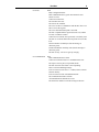
The following table shows the supported adapter cards and the needed software
component from the SIMATIC NET Setup:
Software Component
PC Adapter Card
PROFIBUS Softnet S7
CP5411, CP5511, CP5611, MPI Board
PROFIBUS S7-5412
CP5412A2
PROFIBUS S7-5613
CP5613
Industrial Ethernet S7-1413
CP1413
Industrial Ethernet S7-1613
CP1613
Industrial Ethernet SOFTNET-S7 BASIC/EXTENDED
CP1411, CP1511, 3COM Network Adapter
Note The Siemens S7 server was specifically designed and tested against adapter cards
CP5411, CP5412A2, CP5613, CP1413, CP1613, and 3Com Network Adapter, but other
cards listed above may be compatible.
Required Driver Configuration
Siemens driver configuration is required at both ends of the PLC communication link.
The PC with its CP card(s) and one or more PLCs with their CP cards must all be
configured to work together before operating the server.
The Siemens adapter cards and drivers on an NT operating system are easy to install and
configure. The PLCs are more difficult to install and configure. Please refer to the
instructions included with the Siemens supplied driver software and card configuration
tools.
The server can be run to generate server (also called topic) configuration files without
any cards or drivers installed. This is not recommended as it eliminates most of the
server’s ability to detect configuration errors.
4
Wonderware Siemens SIMATIC NET S7 I/O Server
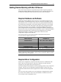
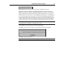
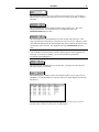
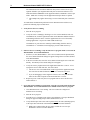
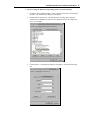
S7 Main Window
Double-click on the server’s icon to start.
When the server starts, the main window will appear:
The current configuration file and its full path are displayed in the main window title
bar. If any topics are active, they will appear in the client area of this window called the
topic monitor list.
View Menu
The View menu has two options that change the appearance of the main window. Both
options are enabled or disabled by selecting the menu option. A check next to the
option indicates the option is enabled.
Toolbar option adds (when enabled) or removes the toolbar (small buttons) located
below the menu.
Status Bar option adds (when enabled) or removes the status indication bar located at
bottom of window.
The main window shown above has both options enabled. The main window shown
below has both options disabled.
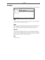
File Menu
5
File Menu
File menu options deal with loading and saving the internal topic configuration database.
New
Clears the internal topic database for a new topic configuration. This menu is disabled
when the server is active (a client is connected).
Open
Replaces the internal topic database with the information contained in the user selected
topic configuration file. This file is automatically loaded the next time the server is
started. This menu is disabled when the server is active (a client is connected).
Save As
Saves the internal topic database under a new name. This command is only needed if
you want to save the configuration under a different name. If you edit the internal topic
database, the data is stored automatically in the current configuration file. This menu is
disabled when the server is active (a client is connected).
Exit
Terminates the server.
6
Wonderware Siemens SIMATIC NET S7 I/O Server
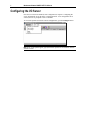
Configuring the I/O Server
Once the server has been installed, some configuration is required. Configuring the
server automatically saves the data in a configuration file. If no configuration file is
selected, the user is prompted to select a filename.
To access the options used for the various configurations, open the Configure menu:
Note If any of the options appear grayed, then these options are not available with this
software version.
Configuring Automatic Topic Generation
7
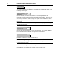
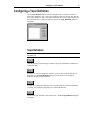
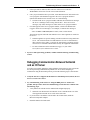
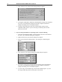
Configuring Automatic Topic Generation
The Automatic Topic Generation option is used to automatically generate all topics
according to the Siemens SIMATIC NET S7 configuration. All combinations of CP
names and connection names are automatically used to create a unique topic name.
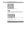
When the Automatic Topic Generation option is selected, the Automatic Topic
Generation dialog box appears:
Automatic Topic Generation
This dialog allows you to generate all topics according to your Siemens SIMATIC NET
S7 configuration. All combinations of CP names and connection names are used to
create a unique topic name.
Select the option of the strategy that will be used to handle existing topics in the current
configuration.
Select this option to delete all previously defined topics.
Previously defined topics that conflict with the automatically generated topic names will
be replaced by the new topics.
8
Wonderware Siemens SIMATIC NET S7 I/O Server
This option is selected when adding new names and is the safest (default) mode. It will
not change existing topics.
Enter the frequency (in milliseconds) that the server will acquire data for the
items/points associated with all the topics generated by this procedure. The lowest nonzero value you can enter is 100ms for topics with cyclic services and 10ms for topics
that have cyclic services disabled. If you enter zero, no PLC item on these topics will be
updated at all.
Note Generate a set of topics with different update intervals by using different strings to
append to the topic names.
Enter the name to be appended to all newly generated topics. For example, 'fast' for
topics with a short interval and 'slow' for topics with a long interval.
Disables S7 cyclic services for all generated topics.
Note When creating a configuration from scratch, there are no differences between the
three modes. All other configuration points available in the topic definition dialog box
are filled with default values.
Click OK to save changes and close the dialog box.
Click Cancel to close the dialog box without changing current settings.
Configuring a Topic Definition
9
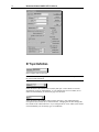
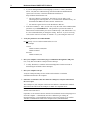
Configuring a Topic Definition
Use the Topic Definition option from the Configure menu to create new, modify, or
delete topic definitions. One or more topic definitions must exist for each PLC that the
server will communicate with. Each topic definition must contain a unique name for the
PLC associated with it. When this option is selected, the Topic Definition dialog box
will appear:
Topic Definition
Note Once topics have been defined, their names will be listed in the Topics section of
this dialog box.
Click this button to close the dialog box and accept any new definitions, modifications
or deletions made.
To modify or view an existing topic definition, select its name in the list and click on
this button. The S7 Topic Definition dialog box (described below) will appear
displaying the selected topic definition.
To delete an existing topic definition, select its name in the list and click on this button.
A message box will appear prompting you to confirm the deletion.
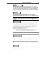
To add a new topic definition, click on this button. The S7 Topic Definition dialog box
will appear:
10
Wonderware Siemens SIMATIC NET S7 I/O Server
S7 Topic Definition
Enter a unique name for the topic.
Note When communicating with InTouch, this exact name is used as the topic name in
the Access Name definition.
Select the name of the CP that will be used by this topic. These names are read out
automatically of the S7 SAPI database. If you configure the S7 server offline (no S7
SAPI or board installed) you can directly type in a CP name.
Select the name of the VFD that will be used by this topic. Only VFD names that
correspond to the selected CP are found in the list. Changing the CP name changes the
list contents of the VFD combo box. If you configure the S7 server offline (no S7 SAPI
or board installed) you can directly type in a VFD name.
Configuring a Topic Definition
11
Select the name of the connection that will be used by this topic. Only connection
names that correspond to the selected CP and VFD are found in the list. Changing the
CP name and/or changing the VFD name changes the list contents of the connection
combo box. If you configure the S7 IO server offline (no S7 SAPI or board installed)
you can directly type in a connection name.
Enter the frequency (in milliseconds) that the server will acquire date for the
items/points associated with this topic. If set to zero, the server will not poll the PLC to
gather data.
Note Different items/points can be polled at different rates in a PLC by defining
multiple topic names for the same PLC and setting a different Update Interval in each
of the topics.
Select this option to disable the S7 SAPI cyclic services for items/points on this topic.
Cyclic services have a reliable update frequency and need less bus access. Cyclic
services are a limited resource in the PLC and/or Communication Processor. If this
option is selected, the server polls all items/points in this topic. If this option is not
selected, the server tries to register as many point/items in the cyclic services as
possible. The remaining points/items will be polled.
Some reasons for disabling cyclic services:
• A topic with a long interval should not occupy the cyclic service resource
• To force the server to attempt to collect data faster than 100ms
Note The mode 'cyclic' or 'poll' can be observed for each item in the monitor window.
See the section ‘S7 Data Monitor’for further informations.
Enable this option to allow client modification of the update interval while the server is
in operation. If enabled, a client can read and write the update interval on this topic
using the item name UPDATEINTERVAL. If disabled, the client can only read the
Update Interval configured for the topic.
Note The actual update interval for the slowest item on this topic can be read using the
item name MAXINTERVAL. This gives you an indication of the performance of your
configuration during operation.
Selecting this option forces the server to read input and output blocks (also peripherals)
only if their address spaces are contiguous. Check this if you have some holes in your
PLC’s input or output address space.
12
Wonderware Siemens SIMATIC NET S7 I/O Server
With this 3 radio buttons you are able to tune the poking behaviour to the PLC. The 3
modes behave as follows.
Control mode: This mode makes no folding of write values. This should be selected
when using this topic with control clients like InBatch and InControl. If selected the
server processes all poked values in the order they are received from a client and makes
no folding of poke values.
Transition mode: This mode implements poke optimization except the server receives
more than one value per item in one timeslice. If this happens only the first, the second
and the last value is poked. This is the default selection and preserves InTouch sliders
from stuttering.
Full optimization: This mode tells the server that he should build poke messages
regardless of folding and poke order aspects.
Note The highest performance can be achieved with the Full optimization mode. But if
you must be aware of the poke order and that no intermediate poke value is lost you
have to choose the Control mode.
Choose one of these buttons to configure which optimization mode the server should use
to get data from the PLC.
By default, the Auto mode is best to use when exploiting the whole PDU. The Auto
mode should have the best performance in cases where you are not making too many
activations and deactivations.
The Block read mode always registers a whole byte array containing some items. If you
frequently switch items (activating and deactivating) that have similar addresses, this
would be the best selection. In this mode, there are less activations and deactivations on
the protocol.
The S7 SAPI mode is the same optimization mode used in the pre-release of the former
S7 server. This mode has been implemented to keep the server compatible to the former
server. This should be the less preferred optimization mode.
If you know how many services the remote PLC could handle this dialog box limits the
use of cyclic services in this topic and can distribute the available cyclic services among
the topics associated with this connection.
Configuring a Topic Definition
13
Timeouts are needed for block services to supervise the reading of initial values and
updating the block items to this connection. A timeout value 0 disables the time
supervision of block messages. Block services are unconfirmed services. If the remote
station does not send data within this time range, the block service is reinitialized again
and an error message is displayed in the WWLogger.
Select if Alarms or Events will be available in this topic.
Note On one SIMATIC NET connection only Alarms or Events are possible. If you
need Alarms and Events in the same client application you need to create topics on two
different connections (VFD’s).
You can reach the Automatic Topic Generation dialog box using this button (refer to
the associated section to get help in generating topics automatically).
Click OK to save changes and close the dialog box.
Click Cancel to close the dialog box without changing current settings.
14
Wonderware Siemens SIMATIC NET S7 I/O Server
Configuring the I/O Server Settings
Use the Server Settings option from the Configure menu to change the protocol timer,
network using Wonderware NetDDE, change the default configuration file path, or to
enable the server to start automatically as a Windows NT service.
Note When configuring the server on Windows NT, the user must be logged on with
system administrator privileges. This will ensure that updates to the system registry may
be performed.
When the Server Settings option is selected, the Server Settings dialog box will
appear:
Server Settings
Enter the frequency (in milliseconds) that the server is to check for data to process. This
should be approximately two to four times faster than the fastest rate desired to update
data from the equipment.
Note The default protocol timer tick value will vary between servers.
Select this option if you are networking using Wonderware NetDDE.
To create a new default configuration file, enter the complete path for the directory in
which the file is to be saved in this field. This new path will automatically be written to
the WIN.INI file and the server will use this path to load its configuration file the next
time it is started.
Configuring the I/O Server Settings
15
Enabling this option will cause the server to start as a Windows NT service.
Windows NT offers the capability of running applications even when a user is not
logged on to the system. This is valuable when systems must operate in an unattended
mode. Enabling this option and rebooting the system will cause the server to run as a
Windows NT service. However, to view configuration information or to reconfigure the
server, the user must log on to the system. Any server related problems that may arise
such as missing adapter cards, licensing failures or device drivers not loading will not be
visible to the user until a log on is performed. Disabling this option and rebooting the
system will cause the server to run as a Windows NT application program once again.
Note It is highly recommended that the server is configured and communicating
successfully prior to running it as a Windows NT service.
Click Cancel to close the dialog box without saving changes.
Click OK to accept the server settings. The following message box will appear:
Click OK to close the dialog box.
Note You must restart the server for the changes to take effect.
16
Wonderware Siemens SIMATIC NET S7 I/O Server
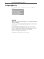
Configuring Security
Use the Security option from the configure menu to control server configuration
changes.
Security
When the server is not active (no clients connected), all server configuration options are
available for modification.
The default setting for Allow configuration while topics are active is disabled. When
disabled, all topics are viewable but locked against changes while the server is active (a
client is connected).
Enable Allow configuration while topics are active to allow write access to some
parameters of the topic configuration while the server is active. This server supports
write access to Update Interval and Enable Access to Update Interval. You cannot
add, delete, rename or change other parameters of a topic configuration.
Click OK to save changes and close the dialog box.
Click Cancel to close the dialog box without saving changes.
Configuring Logger
17
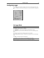
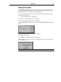
Configuring Logger
Use the Logger option from the configure menu to set the working logger mode of the
server. The options controlled by this dialog box are NOT retained in the configuration
file.
Set Logger Mode
Note Each time the server starts, the logger mode will default to ERRORS.
Select OFF to disable normal server logging.
Select ERRORS for normal operation logging to the Wonderware Logger.
Select TRACE to log errors and all activation/deactivation activities including calls to
the S7.
Select ALL to log all activities including single item value updates.
Enable Show protocol to add PLC communication message data to the selected logger
mode.
Click OK to use changes and close the dialog box.
Click Cancel to close the dialog box without changing current settings.
Note When logging activity increases, the server’s performance degrades.
18
Wonderware Siemens SIMATIC NET S7 I/O Server
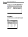
Data Menu
The Data menu contains two commands, Monitor and Dump Active Data, that are
used for diagnostic purposes during runtime (when a client is attached). The remaining
command, DB Dump, is used to transfer the internal topic database to InTouch.
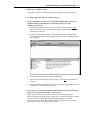
S7 Data Monitor
Use the Monitor option from the data menu to display information about a selected
topic with active items or errors. The information is updated as it changes. This is a
useful tool for tracking down errors, for determining performance and to validate item
values. When the Monitor option is selected, the S7 Data Monitor dialog box will
appear.
Data Menu
19
This drop down list box allows you to select any of the active topics. A preceding ‘*’
indicates that at least one item in this topic has an error while a preceding ‘#’indicates
bad status.
This field displays the current configured update interval of the topic. This value
changes whenever the value is poked via I/O. The displayed value is the
UPDATEINTERVAL item value.
This field displays the current update interval of the slowest item of the topic. This
value is measured for each poll cycle and each received cyclic service indication. If this
value drastically differs from the desired update interval the communication media is not
fast enough to satisfy the load. The displayed value is the MAXINTERVAL item
value.
Note Both values: update interval and longest interval are accessible via I/O. You can
create an WindowView performance meter by displaying these values graphically for
each topic. If I/O access is enabled, you can even tune the bus performance
conveniently from WindowView.
This line shows the available PDU size for this topic. The larger the value, the more
data can be send in one message.
This field displays the number of active items and the number of items with errors (in
parenthesis). If you check this box, only items with errors will be displayed in the item
data list box.
The item list box adapts to the size of the dialog box. So you can resize it for your
personal needs. The server will save the size and position.
20
Wonderware Siemens SIMATIC NET S7 I/O Server
The item data list box displays information about each item. The box is divided into 6
columns. The first column displays the message type and the orderid of the message
which contains this item (‚P‘for a polled message and ‚C‘for a cyclic message). The
second column shows the filling of the request and response PDU. The maximum value
is the PDU size shown above in the monitor window. The third column displays the
data quality. The fourth column shows the timestamp of the last update of that item.
The fifth column shows the raw item value prior to conversion in HEX. Only message
data are displayed as an ASCII string and real data in a short real format. The last
column contains the item name.
There are six basic data quality states an item can have:
Data quality good
00C0
Data communications are good. Data is good.
The register was read or written without any problems
converting the data.
Clamp hi
0056
Data communications are good. Data is not good.
The data is clamped at high limit.
The register was read or written OK but it was necessary to
clamp its value to a limit.
The value is larger than the maximum allowed.
A string is truncated.
Example: A floating point value is clamped to
FLT_MAX.
Clamp lo
0055
Data communications are good. Data is not good.
The data is clamped at low limit.
The register was read or written OK but it was necessary to
clamp its value to a limit.
The value is smaller than the minimum allowed.
Cannot convert
0040
Data communications are good. Data is not good.
The data could not be converted.
The server may return either a constant in place of the data
or return quality information alone.
The data is not useable, it is not known whether the value
is too large or too small.
Incorrect data type.
Floating point not-a-number.
Example: 0x000a in a PLC BCD register.
Data Menu
21
No access
0004
Bad, Configuration Error.
Data communications are good. Data cannot be sent
and/or received.
Cannot access the item.
The item does not exist.
The item is not available.
The server is able to communicate with the PLC but is not
able to access the register.
The server determined the point is not valid.
The PLC responds that the register does not exist, cannot
be read, or cannot be written.
Cannot access a fenced, write-protected, or read-only item.
The PLC is in a mode which does not permit access to this
item.
Incorrect number of data bytes (but the message is
otherwise good).
Invalid command or invalid op code (but the message is
otherwise good).
The PLC is busy. The server gave up retrying.
No communication
0018
Data communications are down.
Cannot access the PLC due to a communications error.
The topic is in slow poll (or equivalent) mode.
The PLC does not exist and/or is not responding.
There is no link validating message.
Lack or resources in the server. A TSR (or driver) cannot
allocate memory.
Lack of resources in the communications link.
The communications link is off-line.
All communications channels are in use.
The network is unable to route the message to the PLC.
22
Wonderware Siemens SIMATIC NET S7 I/O Server
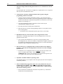
Click on an item line to open a dialog box displaying the item properties:
Click OK to return to the S7 Data Monitor dialog box.
Click Dump to dump the contents of the monitor window into an ASCII text file. The
resulting file can be loaded into Excel or any standard text editor. All columns are
separated by tabs. After the dump is complete, a message box containing the newly
created ASCII text file name is displayed.
The server automatically generates the ASCII text file name and sets the files location
using the following pattern:
<current working directory>\datmonXX.txt
Where XX is a two digit number between 00 and 99. S7 increments the number each
time a file is dumped.
Note Existing files with the same name are erased.
Click OK to return to the S7 Data Monitor dialog box.
Data Menu
23
Dump Active Data
Use the Dump Active Data option from the data menu to dump information on topics
with active items into an ASCII text file. The resulting file can be loaded into Excel or
any standard text editor. All columns are separated by tabs.
The server automatically generates the ASCII text file name and sets the files location
using the following pattern:
<current working directory>\datdmpXX.txt
Where XX is a two digit number between 00 and 99.
The server increments XX each time a file is dumped.
When the Dump Active Data option is selected, the Dump Active Data dialog box will
appear.
Enable Errors only option to dump topics with errors.
Click OK to start the dump.
Click Cancel to close dialog without creating dump file.
After the dump is complete, a message box containing the newly created ASCII text file
name is displayed.
Note Existing files with the same name are erased.
24
Wonderware Siemens SIMATIC NET S7 I/O Server
Dump Topic Database
Use the DB Dump option from the data menu to dump the internal topic database into a
CSV format file. Wonderware’s DbLoad utility can use the resulting file to
automatically generate InTouch access names.
Create the file by selecting a directory and filename using the standard dialog shown
below:
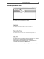
Accessing I/O Server Help
25
Accessing I/O Server Help
The Help menu contains two commands that are used to access help for the server.
The following briefly describes the Help menu options.
Contents
This option is used to display the table of contents for the Help file.
How to Use Help
This option is used to access a list of basic instructions for using the Help file.
About S7
This option is used to access miscellaneous information regarding the server, such as the
software version, the copyright information, license information, etc.
Your FactorySuite system license information can be viewed through the license
viewing utility that is launched from the About dialog box.
$ For more information on obtaining technical support, see your online FactorySuite
System Administrator’s Guide.
26
Wonderware Siemens SIMATIC NET S7 I/O Server
Item Names
The Wonderware Siemens SIMATIC NET S7 IO Server uses an item naming
convention based on the two letter data type identifiers that are used in programming
Siemens PLCs. With one exception, the Siemens SIMATIC NET S7 IO Server accepts
both German and English standard identifiers.
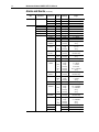
Siemens SIMATIC S7 PLC Item Naming
The following tables represent the Item Naming for the Siemens SIMATIC S7 PLC.
The ranges specified below may vary according to the type of controller being used.
Item Names
27
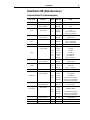
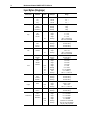
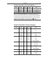
Data Blocks DB (Datenbausteine)
Instance Blocks DI (Instanzbausteine)
Data Format
Item/Point
Suffix
Data Type
Range
Bit
D<B,I>d,Xx.y
Discrete
0 or 1
String
D<B,I>d,Sx,v
Message
String
D<B,I>d,STRINGx,v
Message
String
D<B,I>d,Bx
Integer
0 to 255
D<B,I>d,BYTEx
Integer
0 to 255
Message
1990-1-1-0:00:00.000 to
2089-12-31-23:59:59.999
D<B,I>d,Bx,v
Message
Hex ASCII String
D<B,I>d,BYTEx,v
Message
Hex ASCII String
D<B,I>d,CHARx
Integer
-128 to 127
Message
1990-1-1-0:00:00.000 to
2089-12-31-23:59:59.999
D<B,I>d,CHARx,v
Message
Hex ASCII String
D<B,I>d,Wn
Integer
0 to 65535
D<B,I>d,WORDn
Integer
0 to 65535
Byte
DT
Byte Array
Char
Char Array
DT
Word
Word Array
BCD
Integer
0 to 9999
KT
Message
0.0 to 999.3
S5T
Message
0ms to 2h46m30s
TR
Real
0.0 to 9990.0 (s)
D
Message
1990-1-1 to 2168-12-31
D<B,I>d,Wn,v
Message
Hex ASCII String
D<B,I>d,WORDn,v
Message
Hex ASCII String
Integer
-32768 to 32767
D<B,I>d,INTn
Integer
Integer Array
BCD
Integer
-999 to 999
D
Message
1990-1-1 to 2168-12-31
D<B,I>d,INTn,v
Message
Hex ASCII String
D<B,I>d,Dm
Integer
0 to 2147483647
Integer
0 to 2147483647
D<B,I>d,DWORDm
Double Word
Double Word Array
Integer
0 to 99999999
TOD
Message
0:00:00.000 to 23:59:59.999
T
Message
-24D_20H_31M_23S_648MS to
24D_20H_31M_23S_647MS
D<B,I>d,Dm,v
Message
Hex ASCII String
D<B,I>d,DWORDm,v
Message
Hex ASCII String
D<B,I>d,DINTm
Integer
Double Integer
Double Integer Array
BCD
-2147483648 to 2147483647
-9999999 to 9999999
BCD
TOD
Integer
Message
T
Message
-24D_20H_31M_23S_648MS to
24D_20H_31M_23S_647MS
0:00:00.000 to 23:59:59.999
D<B,I>d,DINTm,v
Message
Hex ASCII String
Real
D<B,I>d,REALm
Real
±3.4e38
Real Array
D<B,I>d,REALm,v
Message
Hex ASCII String
28
Wonderware Siemens SIMATIC NET S7 I/O Server
Note All Data Blocks are Read/Write (d=1 to 65,535, x=0 to 65,535, n=0 to 65,534,
m=0 to 65,532, y=0 to 7, v=1 to net PDU data size/type size - header information, this
size may vary). The longest string or array that can be read in a cyclic service has the
length of the PDU size minus 32 bytes. The longest string InTouch can process is 131
bytes. The longest string that can be poked is 256 bytes or the PDU size minus 28
bytes, whichever is less. Arrays are converted into HEXASCII strings representing the
big endian format of the binary data. The Wonderware Siemens SIMATIC NET S7 I/O
Server will process a write (POKE) to a Data Block. Examples: DB123,W24;
DB23,DINT10BCD; DI5,X2.0; DI6,BYTE4,10.
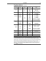
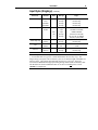
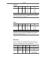
Flag Bytes (Merker)
Data Format
Item/Point
Suffix
Data Type
Range
Bit
FXx.y
MXx.y
Discrete
Discrete
0 or 1
0 or 1
String
FSx,v
MSx,v
FSTRINGx,v
MSTRINGx,v
Message
Message
Message
Message
String
String
String
String
FBx
MBx
FBYTEx
MBYTEx
Integer
Integer
Integer
Integer
Message
0 to 255
0 to 255
0 to 255
0 to 255
1990-1-1-0:00:00.000 to
2089-12-31-23:59:59.999
Hex ASCII String
Hex ASCII String
Hex ASCII String
Hex ASCII String
Byte
DT
Byte Array
Char
FBx,v
MBx,v
FBYTEx,v
MBYTEx,v
Message
Message
Message
Message
FCHARx
MCHARx
Integer
Integer
Message
FCHARx,v
MCHARx,v
Message
Message
-128 to 127
-128 to 127
1990-1-1-0:00:00.000 to
2089-12-31-23:59:59.999
Hex ASCII String
Hex ASCII String
FWn
MWn
FWORDn
MWORDn
Integer
Integer
Integer
Integer
Integer
Message
Message
Real
Message
Message
Message
Message
Message
0 to 65535
0 to 65535
0 to 65535
0 to 65535
0 to 9999
0.0 to 999.3
0ms to 2h46m30s
0.0 to 9990.0 (s)
1990-1-1 to 2168-12-31
Hex ASCII String
Hex ASCII String
Hex ASCII String
Hex ASCII String
DT
Char Array
Word
Word Array
BCD
KT
S5T
TR
D
FWn,v
MWn,v
FWORDn,v
MWORDn,v
Item Names
Flag Bytes (Merker)
Data Format
Integer
Integer Array
Double Word
Item/Point
(continued)
Suffix
Data Type
Range
BCD
D
Integer
Integer
Integer
Message
Message
Message
-32768 to 32767
-32768 to 32767
-999 to 999
1990-1-1 to 2168-12-31
Hex ASCII String
Hex ASCII String
FINTn
MINTn
FINTn,v
MINTn,v
FDm
MDm
FDWORDm
MDWORDm
BCD
TOD
T
Double Word
Array
Double
Integer
29
FDm,v
MDm,v
FDWORDm,v
MDWORDm,v
Integer
Integer
Integer
Integer
Integer
Message
Message
Message
to 2147483647
to 2147483647
to 2147483647
to 2147483647
0 to 99999999
0:00:00.000 to 23:59:59.999
-24D_20H_31M_23S_648MS to
24D_20H_31M_23S_647MS
Hex ASCII String
Message
Message
Hex ASCII String
Hex ASCII String
-2147483648 to 2147483647
-2147483648 to 2147483647
-9999999 to 9999999
FDINTm
BCD
Integer
Integer
Integer
MDINTm
TOD
T
Message
Message
0
0
0
0
Double
Integer Array
FDINTm,v
MDINTm,v
Message
Message
0:00:00.000 to 23:59:59.999
-24D_20H_31M_23S_648MS to
24D_20H_31M_23S_647MS
Hex ASCII String
Hex ASCII String
Real
FREALm
MREALm
Real
±3.4e38
Real Array
FREALm,v
MREALm,v
Message
Hex ASCII String
Note All Flags are Read/Write (x=0 to 65,535, y=0 to 7, n=0 to 65,534, m=0 to 65,532,
v=1 to net PDU data size/type size - header information, this size may vary). The
longest string or array that can be read in a cyclic service has the length of the PDU size
minus 32 bytes. The longest string InTouch can process is 131 bytes. The longest string
that can be poked is 256 bytes or the PDU size minus 28 bytes, whichever is less.
Arrays are converted into HEXASCII strings representing the big endian format of the
binary data. The Wonderware Siemens SIMATIC NET S7 I/O Server will process a
write (POKE) to a Flag Byte.
30
Wonderware Siemens SIMATIC NET S7 I/O Server
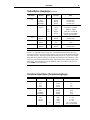
Input Bytes (Eingänge)
Data Format
Item/Point
Bit
Ix.y
Ex.y
IXx.y
EXx.y
Discrete
Discrete
Discrete
Discrete
0
0
0
0
String
ISx,v
ESx,v
ISTRINGx,v
ESTRINGx,v
Message
Message
Message
Message
String
String
String
String
IBx
EBx
IBYTEx
EBYTEx
Integer
Integer
Integer
Integer
Message
0 to 255
0 to 255
0 to 255
0 to 255
1990-1-1-0:00:00.000 to
2089-12-31-23:59:59.999
Hex ASCII String
Hex ASCII String
Hex ASCII String
Hex ASCII String
Byte
Suffix
DT
Byte Array
Char
IBx,v
EBx,v
IBYTEx,v
EBYTEx,v
Message
Message
Message
Message
ICHARx
ECHARx
Integer
Integer
Message
IWn
EWn
IWORDn
EWORDn
BCD
KT
S5T
TR
D
Integer
Integer
Integer
Integer
Integer
Message
Message
Real
Message
Message
Message
Message
Message
0 to 65535
0 to 65535
0 to 65535
0 to 65535
0 to 9999
0.0 to 999.3
0ms to 2h46m30s
0.0 to 9990.0 (s)
1990-1-1 to 2168-12-31
Hex ASCII String
Hex ASCII String
Hex ASCII String
Hex ASCII String
BCD
D
Integer
Integer
Integer
Message
Message
Message
-32768 to 32767
-32768 to 32767
-999 to 999
1990-1-1 to 2168-12-31
Hex ASCII String
Hex ASCII String
IWn,v
EWn,v
IWORDn,v
EWORDn,v
Integer
Double Word
1
1
1
1
Message
Message
IINTn
EINTn
Integer Array
or
or
or
or
ICHARx,v
ECHARx,v
Word
Word Array
Range
-128 to 127
-128 to 127
1990-1-1-0:00:00.000 to
2089-12-31-23:59:59.999
Hex ASCII String
Hex ASCII String
DT
Char Array
Data Type
IINTn,v
EINTn,v
IDm
EDm
IDWORDm
EDWORDm
BCD
TOD
T
Integer
Integer
Integer
Integer
Integer
Message
Message
0
0
0
0
to 2147483647
to 2147483647
to 2147483647
to 2147483647
0 to 99999999
0:00:00.000 to 23:59:59.999
-24D_20H_31M_23S_648MS to
24D_20H_31M_23S_647MS
Item Names
31
Input Bytes (Eingänge) (continued)
Data Format
Double Word Array
Double Integer
Item/Point
Suffix
IDm,v
Message
Hex ASCII String
Message
Hex ASCII String
IDWORDm,v
Message
Hex ASCII String
EDWORDm,v
Message
Hex ASCII String
IDINTm
Integer
-2147483648 to 2147483647
Integer
-2147483648 to 2147483647
Integer
-9999999 to 9999999
BCD
Real
Real Array
Range
EDm,v
EDINTm
Double Integer Array
Data Type
TOD
Message
0:00:00.000 to 23:59:59.999
T
Message
-24D_20H_31M_23S_648MS to
24D_20H_31M_23S_647MS
IDINTm,v
Message
Hex ASCII String
EDINTm,v
Message
Hex ASCII String
IREALm
Real
±3.4e38
EREALm
Real
±3.4e38
IREALm,v
Message
Hex ASCII String
EREALm,v
Message
Hex ASCII String
Note All Inputs are Read Only (x=0 to 65,535, y=0 to 7, n=0 to 65,534, m=0 to 65,532,
v=1 to net PDU data size/type size - header information, this size may vary). The
longest string or array that can be read in a cyclic service has the length of the PDU size
minus 32 bytes. The longest string InTouch can process is 131 bytes. Arrays are
converted into HEXASCII strings representing the big endian format of the binary data.
The Wonderware Siemens SIMATIC NET S7 I/O Server will not process a write
(POKE) to an Input Byte.
32
Wonderware Siemens SIMATIC NET S7 I/O Server
Output Bytes (Ausgänge)
Data Format
Item/Point
Suffix
Data Type
Range
Bit
Ox.y
Ax.y
OXx.y
AXx.y
Discrete
Discrete
Discrete
Discrete
0 or 1
0 or 1
0 or 1
0 or 1
String
OSx,v
ASx,v
OSTRINGx,v
ASTRINGx,v
Message
Message
Message
Message
String
String
String
String
Byte
OBx
ABx
OBYTEx
ABYTEx
Integer
Integer
Integer
Integer
Message
0 to 255
0 to 255
0 to 255
0 to 255
1990-1-1-0:00:00.000 to
2089-12-31-23:59:59.999
DT
Byte Array
OBx,v
ABx,v
OBYTEx,v
ABYTEx,v
Message
Message
Message
Message
Hex ASCII String
Hex ASCII String
Hex ASCII String
Hex ASCII String
Char
OCHARx
ACHARx
Integer
Integer
Message
-128 to 127
-128 to 127
1990-1-1-0:00:00.000 to
2089-12-31-23:59:59.999
DT
Char Array
OCHARx,v
ACHARx,v
Message
Message
Hex ASCII String
Hex ASCII String
Word
OWn
AWn
OWORDn
AWORDn
Integer
Integer
0 to 65535
0 to 65535
Integer
Integer
0 to 65535
0 to 65535
Integer
Message
Message
Real
Message
0 to 9999
0.0 to 999.3
0ms to 2h46m30s
0.0 to 9990.0 (s)
1990-1-1 to 2168-12-31
OWn,v
AWn,v
OWORDn,v
AWORDn,v
Message
Message
Hex ASCII String
Hex ASCII String
Message
Message
Hex ASCII String
Hex ASCII String
OINTn
AINTn
Integer
Integer
Integer
Message
-32768 to 32767
-32768 to 32768
-999 to 999
1990-1-1 to 2168-12-31
BCD
KT
S5T
TR
D
Word Array
Integer
BCD
D
Integer Array
OINTn,v
AINTn,v
Message
Message
Hex ASCII String
Hex ASCII String
Double Word
ODm
ADm
ODWORDm
ADWORDm
Integer
Integer
0 to 2147483647
0 to 2147483647
Integer
Integer
0 to 2147483647
0 to 2147483647
Integer
Message
Message
0 to 99999999
0:00:00.000 to 23:59:59.999
-24D_20H_31M_23S_648MS to
24D_20H_31M_23S_647MS
BCD
TOD
T
Item Names
33
Output Bytes (Ausgänge) (continued)
Data Format
Item/Point
Suffix
Data Type
Range
Double Word
Array
ODm,v
ADm,v
ODWORDm,v
ADWORDm,v
Message
Message
Message
Message
Hex ASCII String
Hex ASCII String
Hex ASCII String
Hex ASCII String
Double Integer
ODINTm
Integer
-2147483648 to 2147483647
ADINTm
Integer
-2147483648 to 2147483647
BCD
Integer
-9999999 to 9999999
TOD
Message
0:00:00.000 to 23:59:59.999
T
Message
-24D_20H_31M_23S_648MS to
24D_20H_31M_23S_647MS
Double Integer
Array
ODINTm,v
Message
Hex ASCII String
ADINTm,v
Message
Hex ASCII String
Real
OREALm
Real
±3.4e38
AREALm
Real
±3.4e38
OREALm,v
Message
Hex ASCII String
AREALm,v
Message
Hex ASCII String
Real Array
Note All Outputs are Read/Write (x=0 to 65,535, y=0 to 7, n=0 to 65,534, m=0 to
65,532, v=1 to net PDU data size/type size - header information, this size may vary).
The longest string or array that can be read in a cyclic service has the length of the PDU
size minus 32 bytes. The longest string InTouch can process is 131 bytes. The longest
string that can be poked is 256 bytes or the PDU size minus 28 bytes, whichever is less.
Arrays are converted into HEXASCII strings representing the big endian format of the
binary data. The Wonderware Siemens SIMATIC NET S7 I/O Server will process a
write (POKE) to an Output Byte.
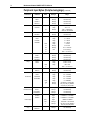
Peripheral Input Bytes (Peripherieeingänge)
Data Format
Item/Point
Suffix
Data Type
Range
Bit
PIx.y
PEx.y
PIXx.y
PEXx.y
Discrete
Discrete
Discrete
Discrete
0
0
0
0
String
PISx,v
PESx,v
PISTRINGx,v
PESTRINGx,v
Message
Message
Message
Message
String
String
String
String
Byte
PIBx
PEBx
PIBYTEx
PEBYTEx
Integer
Integer
Integer
Integer
Message
0 to 255
0 to 255
0 t o 255
0 to 255
1990-1-1-0:00:00.000 to
2089-12-31-23:59:59.999
DT
or
or
or
or
1
1
1
1
34
Wonderware Siemens SIMATIC NET S7 I/O Server
Peripheral Input Bytes (Peripherieeingänge) (continued)
Data Format
Byte Array
Char
Item/Point
Suffix
Word
PIBx,v
Message
Hex ASCII String
Message
Hex ASCII String
PIBYTEx,v
Message
Hex ASCII String
PEBYTEx,v
Message
Hex ASCII String
PICHARx
Integer
-128 to 127
PECHARx
Integer
-128 to 127
Message
1990-1-1-0:00:00.000 to
2089-12-31-23:59:59.999
PICHARx,v
Message
Hex ASCII String
PECHARx,v
Message
Hex ASCII String
PIWn
Integer
0 to 65535
PEWn
Integer
0 to 65535
PIWORDn
Integer
0 to 65535
PEWORDn
Integer
0 to 65535
BCD
Integer
0 to 9999
KT
Message
0.0 to 999.3
S5T
Message
0ms to 2h46m30s
TR
Real
D
Word Array
Integer
PIWn,v
Message
Hex ASCII String
Message
Hex ASCII String
PIWORDn,v
Message
Hex ASCII String
PEWORDn,v
Message
Hex ASCII String
PIINTn
Integer
-32768 to 32767
Integer
-32768 to 32767
BCD
Integer
D
Double Word
Double Word Array
-999 to 999
1990-1-1 to 2168-12-31
PIINTn,v
Message
PEINTn,v
Message
Hex ASCII String
PIDm
Integer
0 to 2147483647
Hex ASCII String
PEDm
Integer
0 to 2147483647
PIDWORDm
Integer
0 to 2147483647
PEDWORDm
Integer
0 to 2147483647
BCD
Integer
0 to 99999999
TOD
Message
0:00:00.000 to 23:59:59.999
T
Message
-24D_20H_31M_23S_648MS to
24D_20H_31M_23S_647MS
PIDm,v
Message
Hex ASCII String
PEDm,v
Message
Hex ASCII String
PIDWORDm,v
Message
Hex ASCII String
PEDWORDm,v
Message
Hex ASCII String
PIDINTm
Integer
-2147483648 to 2147483647
TOD
Integer
Integer
Message
-2147483648 to 2147483647
-9999999 to 9999999
0:00:00.000 to 23:59:59.999
T
Message
-24D_20H_31M_23S_648MS to
24D_20H_31M_23S_647MS
Message
Hex ASCII String
PEDINTm
Double Integer
Double Integer
Array
0.0 to 9990.0 (s)
1990-1-1 to 2168-12-31
PEWn,v
PEINTn
Integer Array
Range
PEBx,v
DT
Char Array
Data Type
BCD
PIDINTm,v
PEDINTm,v
Item Names
35
Peripheral Input Bytes (Peripherieeingänge) (continued)
Data Format
Item/Point
Suffix
Data Type
Range
±3.4e38
±3.4e38
Hex ASCII String
Hex ASCII String
Real
PIREALm
PEREALm
Real
Real
Real Array
PIREALm,v
PEREALm,v
Message
Message
Note All Peripheral Inputs are Read Only (x=0 to 65,535, n=0 to 65,534, m=0 to
65,532, v=1 to net PDU data size/type size - header information, this size may vary).
The longest string or array that can be read in a cyclic service has the length of the PDU
size minus 32 bytes. The longest string InTouch can process is 131 bytes. Arrays are
converted into HEXASCII strings representing the big endian format of the binary data.
The Wonderware Siemens SIMATIC NET S7 I/O Server will not process a write
(POKE) to a Peripheral Input Byte. Some input modules are not readable.
Peripheral Output Bytes (Peripherieausgänge)
Data Format
Bit
String
Byte
Item/Point
Suffix
Char
Discrete
0 or 1
PAx.y
Discrete
0 or 1
POXx.y
Discrete
0 or 1
PAXx.y
Discrete
0 or 1
POSx,v
Message
String
PASx,v
Message
String
POSTRINGx,v
Message
String
PASTRINGx,v
Message
String
POBx
Integer
0 to 255
PABx
Integer
0 to 255
POBYTEx
Integer
0 to 255
PABYTEx
Integer
0 to 255
Message
1990-1-1-0:00:00.000 to
2089-12-31-23:59:59.999
POBx,v
Message
Hex ASCII String
PABx,v
Message
Hex ASCII String
POBYTEx,v
Message
Hex ASCII String
PABYTEx,v
Message
Hex ASCII String
PACHARx
Integer
-128 to 127
POCHARx
Integer
-128 to 127
Message
1990-1-1-0:00:00.000 to
2089-12-31-23:59:59.999
POCHARx,v
Message
Hex ASCII String
PACHARx,v
Message
Hex ASCII String
POWn
Integer
0 to 65535
PAWn
Integer
0 to 65535
POWORDn
Integer
0 to 65535
DT
Char Array
Word
Range
POx.y
DT
Byte Array
Data Type
36
Wonderware Siemens SIMATIC NET S7 I/O Server
Peripheral Output Bytes (Peripherieausgänge) (continued)
Data Format
Item/Point
Suffix
PAWORDn
Data Type
Range
Integer
0 to 65535
BCD
Integer
0 to 9999
KT
Message
0.0 to 999.3
S5T
Message
0ms to 2h46m30s
TR
Real
D
Word Array
Integer
POWn,v
Message
Hex ASCII String
PAWn,v
Message
Hex ASCII String
POWORDn,v
Message
Hex ASCII String
PAWORDn,v
Message
Hex ASCII String
POINTn
Integer
-32768 to 32767
PAINTn
Integer
-32768 to 32767
BCD
Integer
D
Integer Array
Double Word
Double Integer
Double Integer
Array
Real
Real Array
-999 to 999
1990-1-1 to 2168-12-31
POINTn,v
Message
Hex ASCII String
PAINTn,v
Message
Hex ASCII String
PODm
Integer
0 to 2147483647
PADm
Integer
0 to 2147483647
PODWORDm
Integer
0 to 2147483647
Integer
0 to 2147483647
PADWORDm
Double Word
Array
0.0 to 9990.0 (s)
1990-1-1 to 2168-12-31
BCD
Integer
0 to 99999999
TOD
Message
0:00:00.000 to 23:59:59.999
T
Message
-24D_20H_31M_23S_648MS to
24D_20H_31M_23S_647MS
PODm,v
Message
Hex ASCII String
PADm,v
Message
Hex ASCII String
PODINTm
Integer
-2147483648 to 2147483647
Integer
-2147483648 to 2147483647
BCD
Integer
-9999999 to 9999999
TOD
Message
0:00:00.000 to 23:59:59.999
T
Message
-24D_20H_31M_23S_648MS to
24D_20H_31M_23S_647MS
Message
Hex ASCII String
POREALm
Real
±3.4e38
PAREALm
Real
±3.4e38
POREALm,v
Message
Hex ASCII String
PAREALm,v
Message
Hex ASCII String
PADINTm
PODINTm,v
PADINTm,v
Note All Peripheral Outputs are WriteOnly (x=0 to 65,535, n=0 to 65,534, m=0 to
65,532, v=1 to net PDU data size/type size - header information, this size may vary).
The longest string or array that can be read in a cyclic service has the length of the PDU
size minus 32 bytes. The longest string InTouch can process is 131 bytes. The longest
string that can be poked is 256 bytes or the PDU size minus 28 bytes, whichever is less.
Arrays are converted into HEXASCII strings representing the big endian format of the
binary data. The Wonderware Siemens SIMATIC NET S7 I/O Server will process a
write (POKE) to a Peripheral Output Byte. All output modules are not readable but
only POKES are allowed.
Item Names
37
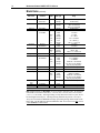
Counters
Data Format
Item/Point
Word
Suffix
Data Type
Range
Cx
None
Integer
0...65535
Zx
None
Integer
0 to 65535
BCD
Integer
0 to 9999
KT
Message
0.0 to 999.3
S5T
Message
0ms to 2h46m30s
Note All Counters are Read/Write (x=0 to 65,535). The Wonderware Siemens
SIMATIC NET S7 I/O Server will process a write (POKE) to a Counter. Although the
S7 server allows to poke any word value into counters, the S7 PLC can only process
values in the range of 0..2457 or 0..999 (BCD).
Timers
Data Format
Word
Item/Point
Suffix
Data Type
Range
Tx
None
Integer
0 to 14745
TREALx
BCD
Integer
0 to 9999
KT
Message
0.0 to 999.3
S5T
Message
0ms to 2h46m30s
None
Real
0.0 to 9990.00
Note All Timers are Read/Write (x=0 to 65,535). The Wonderware Siemens
SIMATIC NET S7 I/O Server will process a write (POKE) to a Timer. Although the
S7 server allows to poke any word value into timers, the S7 PLC can only process
values that represent a valid time format.
Block Items
Block items are available only if a BSEND routine is configured/programmed in the
remote PLC. With these items you are able to read huge data blocks (up to 64kByte)
out of the PLC. These items are only available if your SIMATIC NET driver supports
block services. For more information refer to your Siemens manuals.
Data Format
Item/Point
Suffix
Data Type
Range
Bit
BLd,Xx.y
Discrete
0 or 1
String
BLd,Sx,v
Message
String
BLd,STRINGx,v
Message
String
Byte
BLd,Bx
Integer
0 to 255
BLd,BYTEx
Integer
0 to 255
Message
1990-1-1-0:00:00.000 to
2089-12-31-23:59:59.999
DT
38
Wonderware Siemens SIMATIC NET S7 I/O Server
Block Items (continued)
Data Format
Item/Point
Byte Array
BLd,Bx,v
BLd,BYTEx,v
Char
BLd,CHARx
Suffix
Data Type
Range
Message
Message
Hex ASCII String
Hex ASCII String
Integer
Message
Char Array
BLd,CHARx,v
Message
-128 to 127
1990-1-1-0:00:00.000 to
2089-12-31-23:59:59.999
Hex ASCII String
Word
BLd,Wn
BLd,WORDn
BCD
KT
S5T
TR
D
Integer
Integer
Integer
Message
Message
Real
Message
Integer
Integer
0 to 65535
0 to 65535
0 to 9999
0.0 to 999.3
0ms to 2h46m30s
0.0 to 9990.0 (s)
1990-1-1 to 2168-12-31
0 to 65535
0 to 65535
BCD
D
Integer
Integer
Message
Message
-32768 to 32767
-999 to 999
1990-1-1 to 2168-12-31
Hex ASCII String
Integer
Integer
Integer
Message
Message
0 to 2147483647
0 to 2147483647
0 to 99999999
0:00:00.000 to 23:59:59.999
-24D_20H_31M_23S_648MS to
24D_20H_31M_23S_647MS
Hex ASCII String
DT
Word Array
BLd,Wn,v
BLd,WORDn,v
Integer
BLd,INTn
Integer Array
BLd,INTn,v
Double Word
BLd,Dm
BLd,DWORDm
BCD
TOD
T
Double Word
BLd,Dm,v
Message
Array
BLd,DWORDm,v
Message
Hex ASCII String
Double Integer
BLd,DINTm
Integer
Integer
Message
Message
-2147483648 to 2147483647
-9999999 to 9999999
0:00:00.000 to 23:59:59.999
-24D_20H_31M_23S_648MS to
24D_20H_31M_23S_647MS
Hex ASCII String
BCD
TOD
T
Double Integer
Array
Real
BLd,DINTm,v
Message
BLd,REALm
Real
Real Array
BLd,REALm,v
Message
±3.4e38
Hex ASCII String
Note All Block Items are ReadOnly (d=0 to 4,294,967,296 (this is the r_id configured
in the SFB 12 call in the remote PLC), x=0 to 65,533, n=0 to 65,532, m=0 to 65,530,
y=0 to 7, v=0 to 65534). The longest string or array that can be read in a cyclic service
has the length of 65534 bytes. The longest string InTouch can process is 131 bytes.
Arrays are converted into HEXASCII strings representing the big endian format of the
binary data. The Wonderware Siemens SIMATIC NET S7 I/O Server will not process
a write (POKE) to a Block Item.
Item Names
39
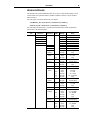
Alarms and Events
The Wonderware Siemens SIMATIC NET S7 I/O Server offers the possibility to read
Alarms and Events generated either by SFB33 to SFB36 (Alarms) or by the Symbol
Editor (Events).
The item syntax for Alarms and Events is as follows:
ALARM<EV_ID>.<Extension 1>[,<Extension 2>[<Suffix>]]
EVENT<EV_ID>.<Extension 1>[,<Extension 2>[<Suffix>]]
For valid values for Extension 1, Extension 2 and Suffix and for valid combinations
please refer to the following table:
Item
Extension 1
ALARM<EV_ID>
Message
Range
EVENT_STATE
Integer
0 to 65535
STATE
ACK_STATE
TIME_STAMP
NO_ADD_VALUES
Integer
Integer
Message
Integer
Message
0 to 65535
0 to 65535
String
0 to 10
String
Xx.y
Integer
Discrete
0 to 65535
0 or 1
Sx,v
STRINGx,v
Message
Message
String
String
Bx
BYTEx
DT
Integer
Integer
Message
Message
Message
0 to 255
0 to 255
String
Hex ASCII String
Hex ASCII String
DT
Integer
Message
Message
-128 to 127
String
Hex ASCII String
BCD
KT
S5T
D
Integer
Integer
Integer
Message
Message
Message
Message
Message
0 to 65535
0 to 65535
0 to 9999
0.0 to 999.3
0ms to 2h46m30s
String
Hex ASCII String
Hex ASCII String
BCD
D
Integer
Integer
Message
Message
-32768 to 32767
0 to 9999
String
Hex ASCII String
BCD
T
TOD
Integer
Integer
Integer
Message
Message
Message
Message
0 to 2147483647
0 to 2147483647
0 to 99999999
String
String
Hex ASCII String
Hex ASCII String
Integer
Integer
Message
Message
-2147483648 to 2147483647
0 to 99999999
String
String
ADD_VALUEw
Extension 2
Suffix
DATA_TYPE
LENGTH
Bx
BYTEx,v
CHARx
CHARx,v
Wn
WORDn
Wn,v
WORDn,v
INTn
INTn,v
Dm
DWORDm
Dm,v
DWORDm,v
DINTm
BCD
T
TOD
40
Wonderware Siemens SIMATIC NET S7 I/O Server
Alarms and Events (continued)
Item
EVENT<EV_ID>
Extension 1
Message
Range
DINTm,v
Message
Hex ASCII String
REALm
Real
REALm,v
Message
±3.4e38
Hex ASCII String
EVENT_STATE
Integer
0 to 65535
STATE
ACK_STATE
TIME_STAMP
NO_ADD_VALUES
Integer
Integer
Message
Integer
Message
0 to 65535
0 to 65535
String
0 to 10
String
Xx.y
Integer
Discrete
0 to 65535
0 or 1
S,v
STRINGx,v
Message
Message
String
String
Bx
BYTEx
DT
Integer
Integer
Message
Message
Message
0 to 255
0 to 255
String
Hex ASCII String
Hex ASCII String
DT
Integer
Message
Message
-128 to 127
String
Hex ASCII String
BCD
KT
S5T
D
Integer
Integer
Integer
Message
Message
Message
Message
Message
0 to 65535
0 to 65535
0 to 9999
0.0 to 999.3
0ms to 2h46m30s
String
Hex ASCII String
Hex ASCII String
BCD
D
Integer
Integer
Message
Message
-32768 to 32767
0 to 9999
String
Hex ASCII String
BCD
T
TOD
Integer
Integer
Integer
Message
Message
Message
Message
0 to 2147483647
0 to 2147483647
0 to 99999999
String
String
Hex ASCII String
Hex ASCII String
BCD
T
TOD
Integer
Integer
Message
Message
Message
-2147483648 to 2147483647
0 to 99999999
String
String
Hex ASCII String
ADD_VALUEw
Extension 2
Suffix
DATA_TYPE
LENGTH
Bx,v
BYTEx,v
CHARx
CHARx,v
Wn
WORDn
Wn,v
WORDn,v
INTn
INTn,v
Dm
DWORDm
Dm,v
DWORDm,v
DINTm
DINTm,v
REALm
Real
±3.4e38
REALm,v
Message
Hex ASCII String
Item Names
41
Note All Alarms and Events are Read only (<EV_ID> is the ID defined by Step7, in
integer format, filled with leading zeros up to 6 characters; w=1 to 10; x=0 to 65,535;
n=0 to 65,534; m=0 to 65,532; y=0 to 7; v=1 to net PDU data size/type size - header
information, this size may vary). The longest string or array that can be read in a cyclic
service has the length of the PDU size minus 32 bytes. The longest string InTouch can
process is 131 bytes. Arrays are converted into HEXASCII strings representing the big
endian format of the binary data. The Wonderware Siemens SIMATIC NET S7 I/O
Server will not process writes (POKES) to Alarms and Events.
Note This version of Wonderware Siemens SIMATIC NET S7 I/O Server does not
allow acknowledgment of Alarms and Events.
Examples:
ALARM000010.TIME_STAMP
EVENT001234.ADD_VALUE2,LENGTH
ALARM000555.ADD_VALUE10,REAL0
EVENT000001.ADD_VALUE3,D0TOD
Some additional explanations:
EVENT_STATE:
State of the Alarm/Event itself. If the Alarm/Event is
TRUE, then EVENT_STATE is TRUE and vice
versa. Please refer to the Step7 documentation for
more detailed information.
STATE:
The state of the communication. Please refer to the
Step7 documentation for more detailed information.
ACK_STATE:
The state of the acknowledgement of coming or going
Alarms/Events. Please refer to the Step7
documentation for more detailed information.
TIME_STAMP:
Time stamp of the Alarm/Event, provided by the PLC.
NO_ADD_VALUES:
Number of additional values that are sent with this
Alarm/Event message.
ADD_VALUEw,DATA_TYPE:
Data type of a specific additional value of an
Alarm/Event
ADD_VALUEw,LENGTH:
Length of a specific additional value of an
Alarm/Event
<EV_ID>:
The event ID is created automatically by the Step7
programming software. In case of Alarms (FB33 to
FB36) this is the EV_ID-parameter of the function
block. The value of the parameter must be converted
from hexadecimal to decimal and then filled up with
leading „0“ to the length of 6 characters (e.g.: EV_ID:
DW#16#4E25 => <EV_ID>: 020005). In case of
Events (Generated by the symbol editor) this is the
„Message Number“. This number is in decimal format
and must be filled with leading „0“ up to 6 characters
(e.g.: „Message number“: 20000 => <EV_ID>:
020000).
42
Wonderware Siemens SIMATIC NET S7 I/O Server
Predefined Item/Point Names
All S7 topics have predefined item/point names to monitor and control communication
properties.
UPDATEINTERVAL Item
The UPDATEINTERVAL item is used to access the currently set update interval. It is
the same value displayed in the monitor window of the S7 server. It indicates the
currently requested update interval in milliseconds. If the corresponding topic is
configured for "Enable I/O access to update interval", a client can poke new values into
this item. In any case the value can always be read through I/O. The range of valid
values differs with respect to the topic settings. The value of zero indicates that no items
on that topic are updated.
I/O Type:
ACCESS:
RANGE:
INTEGER
READ/WRITE (if configured)
1.. 2147483647
0 (topic inactive, no items are updated)
Note By poking a value of zero into the update interval item a client can conveniently
stop all update activities on the corresponding topic without having to deactivate the
items.
MAXINTERVAL Item
The MAXINTERVAL item is used to access the measured maximum update interval in
milliseconds of all items of the corresponding topic for the last completed poll cycle. It
is the same value displayed in the monitor window of the S7 server under "Longest
Interval". This item is read only. The value of the slowest item is displayed.
I/O Type:
ACCESS:
RANGE:
INTEGER
READ
0..2147483647
Note Use the UPDATEINTERVAL and MAXINTERVAL items to conveniently tune
the performance of the communication via I/O.
Predefined Item/Point Names
43
STORESETTINGS Item
The STORESETTINGS item is used to make the temporary update interval changes
via I/O permanent. If the client pokes a value of 1 into the STORESETTINGS item the
currently set update interval is written to the servers configuration file. If the update
interval has been changed via I/O and STORESETTINGS is not poked to 1 the server
will use the original update interval for that topic the next time it is started. Reading the
item will always give 0.
I/O Type:
ACCESS:
RANGE:
DISCRETE
READ/WRITE
0, 1
Note Use this item to conveniently store your optimized configuration via I/O.
ITEMCOUNT Item
The ITEMCOUNT item is used to access the number of active items in the
corresponding topic. It is the same value displayed in the monitor window of the S7
server under "Items". This item is read only.
I/O Type:
ACCESS:
RANGE:
INTEGER
READ
0..2147483647
Note Use the ITEMCOUNT item to monitor the number of currently active items.
ERRORCOUNT Item
The ERRORCOUNT item is used to access the number of active items that have errors
in the corresponding topic. It is the same value displayed in the monitor window of the
S7 server under "errors ( ) only". If the communication status of a topic is bad, all items
have errors (item count equals error count). This item is read only.
I/O Type:
ACCESS:
RANGE:
INTEGER
READ
0..2147483647
Note Use the ERRORCOUNT item to monitor if there are any badly configured items
or invalid item values. This is the case if the topic status is 1 and ERRORCOUNT is
not zero.
44
Wonderware Siemens SIMATIC NET S7 I/O Server
WRITECOMPLETE Item
The WRITECOMPLETE item is used to access the state of pending write activities on
the corresponding topic. If the topic is opened the value of the WRITECOMPLETE
item is initially 1 indicating all write activities are complete - no pokes are pending. If
values are poked into any items of the topic the value of the WRITECOMPLETE item
changes to 0 indicating write activity is currently in progress. If the server has
completed all write activities the value of the WRITECOMPLETE item changes to 1 if
all pokes were successful or to -1 if at least one poke has failed. If the value of the
WRITECOMPLETE item is not zero the client can poke 1 or -1 to it ( poke a 1 to
clear errors or a -1 to test a client reaction on write errors).
I/O Type:
ACCESS:
RANGE:
INTEGER
READ/WRITE
-1,0,1
Note Use the WRITECOMPLETE item to serialize a sequence of poke values into a
single item or to monitor success or failure of poking into one or more items.
STATUS Item
The STATUS item is used to access the state of communication between the server and
PLC. The discrete item, STATUS, is set to 1 when communication is successful or is
set to 0 when communication with the PLC fails.
I/O Type:
ACCESS:
RANGE:
DISCRETE
READ
0,1
Predefined Item/Point Names
45
READCOMPLETE Item
The READCOMPLETE item is used to access the state of initial reads on all items in
the corresponding topic. If the topic is opened and no item is advised, the value of the
READCOMPLETE item is 0. After all activated items have been read once, the
READCOMPLETE item changes to 1. If at least one item could not be read the
READCOMPLETE item alters to –1 indicating there have been read errors.
If at least one new item is advised now READCOMPLETE changes to 0 and after
this/these item(s) has/have been read it changes to 1 or –1 again.
Poking a 0 to this item resets the internal read states of all items in this topic. This resets
the READCOMPLETE item to 0. If all items are read again after this poke, the
READCOMPLETE item changes back to 1 or –1.
I/O Type: INTEGER
ACCESS: READ/WRITE
RANGE:
-1,0,1
POLLNOW Item
Poking a 1 to the predefined POLLNOW item forces all items within this topic to be
read immediately. This is useful if you want to get the newest values from the device,
regardless of its updateinterval. You can use this if you want to trigger the reads within a
topic by your own.
I/O Type:
ACCESS:
RANGE:
DISCRETE
READ/WRITE
0,1
Note You can use POLLNOW and READCOMPLETE for measuring of the longest
interval. Create a topic with updateinterval 0. Poke POLLNOW to 1 and
READCOMPLETE to 0 and store the actual time. Then wait until
READCOMPLETE changes back to 1. The difference between the current time and
the stored time equals the updateinterval.
46
Wonderware Siemens SIMATIC NET S7 I/O Server
Monitoring the Status of Communications with a PLC
For each topic name (PLC), there is a built-in discrete item that can be used to monitor
the status of communications with the PLC. The discrete item, Status, is set to 0 when
communication with the PLC fails and is set to 1 when communication is successful.
Using the Status Item in Excel
The status of the PLC communications can be read into Excel by entering the following
DDE reference formula in a cell on a spreadsheet:
=S7|S7PLC400!Status
where:
S7
Is the name (without extension) of the server application.
S7PLC400
Is the exact topic name defined in the server for the PLC.
Status
Built-in discrete item used to monitor the status of
communications with the PLC.
Monitoring the Status of Communications with InTouch
InTouch supports built-in topic names called DDEStatus and IOStatus that are used to
monitor the status of communications between the server and InTouch. For more
information on the built-in topic names DDEStatus and IOStatus, see your online
”InTouch User’s Guide”.
Using DDEStatus and IOStatus in Excel
The status of communication between the server and InTouch can be read into Excel by
entering the following DDE reference formula in a cell on a spreadsheet:
=view|DDEStatus!S7PLC400
or:
=view|IOStatus!S7PLC400
where:
view
Is the name of the InTouch application.
[DDE][IO]Status
Built-in topic name used to monitor the status of
communications between the server and InTouch.
S7PLC400
The exact access name defined in InTouch for the S7 I/O
server.
Reading Values from the I/O Server into Excel
47
Reading Values from the I/O Server into Excel
Values may be read directly into Excel spreadsheets from the server by entering a DDE
formula into a cell using the following format:
=applicationname|topicname!itemname
Example formula:
=S7|S7PLC400!EW4
where:
S7
Is the name of the server application.
S7PLC400
Is the exact topic name defined in the server for the PLC.
EW4
Is the actual location in the PLC that contains the data value.
This is the item name.
In this example, each time the value of EW4 changes in the PLC, the server will
automatically send the new value to the cell containing the formula in Excel.
Note Refer to the Microsoft Excel manual for complete details on entering Remote
Reference formulas for cells.
48
Wonderware Siemens SIMATIC NET S7 I/O Server
Writing Values to the I/O Server from Excel
Values may be written to the server from Microsoft Excel by creating an Excel macro
that uses the POKE command. The proper command is entered in Excel as follows:
channel=INITIATE("applicationname","topicname")
=POKE(channel,"itemname",Data_Reference)
=TERMINATE(channel)
=RETURN()
The following describes each of the above POKE macro statements:
channel=INITIATE("applicationname","topicname")
Opens a channel to a specific topic name (defined in the server) in a particular
application name (the executable name less the .EXE) and assigns the number of that
opened channel to channel.
Note By using the channel=INITIATE statement the word channel must be used in
the =POKE statement instead of the actual cell reference. The "applicationname"
and "topicname" portions of the formula must be enclosed in quotation marks.
=POKE(channel,"itemname",Data_Reference)
POKEs the value contained in the Data_Reference to the specified item name (actual
location in the PLC) via the channel number returned by the previously executed
INITIATE function. Data_Reference is the row/column ID of the cell containing the
data value.
=TERMINATE(channel)
Closes the channel at the end of the macro. Some applications have a limited number of
channels therefore, they should be closed when finished. Channel is the channel
number returned by the previously executed INITIATE function.
=RETURN()
Marks the end of the macro.
Note Refer to the .XLM sample Excel poke macro provided on the server program disk.
Also refer to the Microsoft Excel manual for complete details on entering Remote
Reference formulas for cells.
Troubleshooting I/O Server Communication Problems 49
Troubleshooting I/O Server Communication Problems
This section provides you with some simple steps that can be taken to ascertain and
correct communication problems. The problems described here represent the most
probable causes of communication failure.
Note This is a general troubleshooting guide and for the sake of brevity we cannot cover
every possible source of communication problems.
Debugging Communication Between InTouch and
an I/O Server
This section explains the most common error situations that can occur when attempting
to establish communication between InTouch and a server.
Servers are Window applications that communicate with I/O, PLCs, and/or other data
sources. If a server supports either the Microsoft Dynamic Data Exchange (DDE) or the
Wonderware SuiteLink protocol, it is capable of communicating with the Wonderware
InTouch program.
Note All Wonderware version 7.0 or later servers support both DDE and SuiteLink.
However, the SuiteLink protocol is only supported on the Windows NT (version 4.0 or
later) operating system.
Servers respond to data requests made by other applications. Requesting applications
are called clients. When WindowViewer acts as a client and requires the value of an
item, it contacts the server and requests the item’s value. The server will report the
value and update WindowViewer only if a change occurs. All WindowViewer data
requests provide information relating an item to a register, coil number, or I/O data point
understood by the server. The server uses the information to automatically handle all
messages to and from I/O, hardware devices (PLC), and/or other data sources.
Note We highly recommend starting all the servers required by the InTouch application
before starting WindowViewer. InTouch (versions prior to 7.0) will display the
Initiating DDE Conversation message box for each uninitiated conversation.
For example:
If you start up WindowViewer and cannot successfully establish a conversation with
a server, the following Initiating DDE Conversation dialog box will appear:
50
Wonderware Siemens SIMATIC NET S7 I/O Server
The information in the second line indicates that you have at least one I/O type
tagname defined in your Tagname Dictionary that is associated with an Access
Name that defines OMRONFO as the Application Name, and HLPLC as the Topic
Name. Make note of exactly how the application and topic names are spelled.
8 This example only applies when using a version of InTouch prior to InTouch
7.0.
To troubleshoot communication problems between WindowViewer and the server,
perform the following steps as listed below:
Ø Verify the I/O Server is running.
1.
Start the server program.
2.
Verify the server is running by checking to see if it is in the Windows Task List.
On Windows NT, click the right mouse button on the Windows taskbar and select
Task Manager from the menu. Click the Applications tab to view all currently
running applications. Or press the CTRL+SHIFT+ESC keys.
On Windows 95, press the ALT+TAB keys while holding down the ALT key.
On Windows 3.1 or Windows for Workgroups, press the CTRL+ESC keys.
Ø If the I/O Server is running, verify the I/O Server's program name is correct in all
WindowMaker Access Name definitions.
1.
Switch to (or start) WindowMaker. Select Access Names from the Special Menu,
the Access Name Definitions dialog box appears listing all Access Names defined
in the WindowMaker.
2.
In the Access Names list, select the Access Name referencing the server and click
Modify. The Modify Access Name dialog box will appear.
3.
Verify the server's program name in the Application Name box is correct. If it is
wrong then correct it and click OK , else click Cancel.
8 The server's exact "executable name" must be typed in the Application Name
box in all Access Name definitions. The ".exe" extension is not used.
8 If you are debugging a remote tagname reference, also verify that the node
name for the remote computer in the Node Name box is correct.
4.
Repeat steps 2 & 3 and verify the server program name is correct in all Access
Names that use it.
Ø If you still cannot establish a conversation, verify the exact topic name used in the
WindowMaker Access Name definitions are defined in the I/O Server program.
1.
Close WindowViewer if it is running. The server cannot be configured if
WindowViewer is running.
2.
Start the server program.
3.
From the server’s Configure menu select Topic Definition. The Topic Definition
dialog box appears listing all topic names defined in the server.
4.
Verify that the topic name exists and is spelled exactly the same (including spaces)
as the topic name referenced in the WindowMaker Access Name definition.
8 Blank spaces cannot follow the topic name in either the server's Topic
Definition or the Access Name definition.
Troubleshooting I/O Server Communication Problems 51
5.
If the topic name is different, either correct it in the server or switch to
WindowMaker and correct it in the Access Name definition.
6.
Once you performed the above procedure, restart WindowViewer and switch to the
server program. Data should now appear in the server’s program window to
indicate that WindowViewer and the server are communicating.
8 The data in the server’s program window indicates the read and write messages
the server is sending to and receiving from the PLC. These are not error
messages; only status messages are written to the server’s program window.
7.
If no data appears in the server’s program window, switch to the Wonderware
Logger to check for error messages. For example, a common error message is:
"Error for DDE: OMRONFO|HLPLC!<null>("item") Advise failed"
This message appears when the item defined in one or more tagnames is invalid for
the server.
8 InTouch tagnames use specific naming conventions when accessing data from a
server. The valid item names for all Wonderware servers are documented in
their respective user's guides. Typically, the item naming conventions used by
each server are consistent with the names used by the equipment manufacturer.
$ For more information on the Wonderware Logger, see your online
FactorySuite System Administrator's Guide.
Ø If you are still experiencing problems, continue with the following troubleshooting
section.
Debugging Communication Between SuiteLink
and an I/O Server
If you have successfully applied the debug techniques listed in the previous section and
are still experiencing communication problems to a server that is attempting to
communicate using the SuiteLink protocol, perform the following steps as listed below:
Ø Verify the I/O Server supports the Wonderware SuiteLink protocol, that is, the I/O
Server is version 7.0 or above.
Ø Try communicating to the I/O Server using the DDE protocol. If this is not
possible, then proceed to the next troubleshooting section otherwise continue with
the following steps:
1.
Verify Microsoft's TCP/IP stack is installed and configured properly.
8 SuiteLink uses the Microsoft TCP/IP stack for its communications even if the
client application and the server reside on the same node.
2.
If you do not have an Ethernet card to bind to the TCP/IP stack, install the
Microsoft Loop Back Adapter.
3.
Install the Microsoft TCP/IP stack.
52
Wonderware Siemens SIMATIC NET S7 I/O Server
Debugging Communication Between an I/O Server
and a PLC
This section provides you with simple steps to diagnose and correct server to PLC
communication problems. The debug techniques listed below address both serial and
board servers. Disregard any information that is not applicable to the server type that
you are using.
When attempting to establish communication between a server and a PLC, if no data
appears in the server's program window and the data items are not updating in
WindowViewer, switch to the Wonderware Logger and check for error messages.
$ For more information on the Wonderware Logger, see your online FactorySuite
System Administrator's Guide.
For example, some of the most common errors that may appear in the Wonderware
Logger for serial servers are:
Response Timeout
WCRET = -2
WakeUp = -2
Receive Overrun
Framing Errors
Note Unless specified otherwise, most serial communication based servers are full
duplex. If you require a server for half duplex (one that monitors the CTS and RTS
lines) or if you are not sure whether the PLC's protocol is full or half duplex, call your
PLC supplier.
Also, during in-house server testing, we have found that the communication cards that
use the National 16450 and 16550 UARTs seem to be less susceptible to level and
timing problems. Cards based on other chips may work, but we recommend using the
National cards. Some of the highly integrated UART chips (most notably, Winbond and
UMC) have a tendency for their transmitters to hang, requiring re-initialization of the
UART. If this occurs, you may have to restart the server or execute the Reinitialize I/O
command from the Special menu in WindowViewer.
Ø Check your cabling to the PLC.
Is it wired correctly? Check for shorts, loose wires, broken wires, crossed wires, and so
on.
8 A continuity tester can be helpful here.
Ø Verify the I/O Server’s serial configuration settings (Parity, Stop Bits, Baud Rate,
Handshaking and so on) against the settings in the hardware device.
Ø Verify the communication port is working properly in Windows.
1.
Close the server program.
8 If you are using a server that requires a TSR, you will not be able to verify that
the port is functioning properly while the TSR is running. Stop all TSRs then
continue with this procedure. If you confirm that the port functions properly
without the TSR running, change your software interrupt (IRQ) to another
number, for example, change 60 to 62.
Troubleshooting I/O Server Communication Problems 53
8 Also, if you are using an AT type computer, two devices cannot share
interrupts. Verify that the communication port you are using has a unique
interrupt setting.
2.
On Windows 3.1 or Windows for Workgroups, start the Terminal program. On
Windows 95 or Windows NT, start the HyperTerminal program.
3.
Configure the Terminal (or HyperTerminal) program to use the same
communication port with the same settings (baud rate, parity, stop bits and so on) as
the hardware device.
4.
Connect a null modem cable to a second computer's port.
5.
On the second computer, start and configure the Terminal (or HyperTerminal)
program with the same settings as the first computer.
6.
Verify that you can send data between the two computers.
8 If you do not have two computers and the computer you are using has another
port, start two instances of the Terminal (or HyperTerminal) program with each
configured to their own port. Then try communicating between them.
8 If you have an external modem, connect the modem to the communication port
that you are testing to see if you can dial out.
7.
If the communication port does not appear to be functioning properly, check your
environment files (AUTOEXE.BAT, CONFIG.SYS, SYSTEM.INI, and
WIN.INI). Look for suspicious programs or drivers that might be taking control of
the port or its interrupt before the server is loaded. Always keep your environment
files as clean as possible. If you are in doubt about an entry, comment it out.
8.
If the previous step was unsuccessful, try another communication port or another
computer.
Note A common misconception of connecting to a PLC with a DOS program and the
same communication port will work in Windows is not the case! Windows is an entirely
different environment than DOS.
Ø What type of UART is on the COM port?
If it’s not a 16550, then you must lower your baud rate to 9600 or slower. Only the
16550 UART can sustain continuous, error free communications at speeds higher than
9600 baud. Other UARTs may work at speeds faster than 9600 baud, but errors may be
written to the Wonderware Logger. For example, "Receive Overruns." To determine
which UART you have, enter MSD at a DOS prompt, then choose COM Ports from the
MSD menu.
Ø If you are running Windows for Workgroups, verify the following:
1.
Add these lines to the [386Enh] section of your SYSTEM.INI file which is located
in your \Windows directory:
EMMEXCLUDE=A000-EFFF
COMxFIFO=0
where x specifies the COM port number. You need to add a separate COMxFIFO
line for each serial port using a 16550 UART chip.
54
Wonderware Siemens SIMATIC NET S7 I/O Server
2.
If you are running Windows for Workgroups (version 3.1 or later), download
SERIAL.386 (this fixes a Microsoft bug) from the Wonderware Bulletin Board
system (949-727-0726) or from the Wonderware WEB site at:
http://wondertech.wonderware.com.
8 The size of this file is 10620 bytes, has a date of 2/17/94, and is a selfextracting zip file called wg1001.exe. It’s located in the "PatchFix Library" on
the Wonderware BBS in the File Transfers / Patchfix area.
8 You must be registered to access the Wonderware Web site.
3.
If the above numbers, 1. and 2., do not work, verify the value of the ComBoostTime
parameter in your SYSTEM.INI file. This parameter represents the number of
milliseconds a virtual machine processes a COM interrupt. (The default value is 2.)
It is not recommended that you change this setting. However, if you are receiving
errors such as "Receive Overruns" or "WCRE=-2", try increasing the value to 20.
Ø Verify the parameters for WWCOMTSR.
Do not specify a receive and/or transmit buffer size of 8!
For example:
Correct:
COM1:0 COM2:1,2048,2048
COM1:0 COM2:1
Incorrect:
COM1:0 COM2:1,8,8
Ø Does your computer crash when trying to communicate through the COM port?
If so, verify that each TSR has a unique software interrupt.
8 A utility, ShowSoft, is available on the Knowledge Base CD that can assist in
determining the available software interrupts.
Ø Does your computer lock up?
Verify the COM port's IRQ’s do not conflict with each other or with other
communication boards in the computer.
Ø If the PLC or field device has more than one COM port, verify the connection to
the correct port.
The COM port on your computer uses the RS-232 hardware communication standard
and connects the cable from the COM port to an RS-232 compliant device.
Note To connect to an RS-422 or RS-485 port on the PLC, you need an RS-232 to RS422/485 conversion device.
If possible, use an external converter instead of a board-based converter that plugs into a
slot in the computer. A board-based converter is difficult to get working for
inexperienced users. If a board-based converter is not set up properly, it can conflict
with other communication boards in the computer such as, internal modems.
Troubleshooting I/O Server Communication Problems 55
Ø If you are using the Windows 95 operating system, verify the following:
1.
Click Start on the Windows taskbar. Point to Settings, then click Control Panel in
the menu. The Control Panel dialog box will appear.
2.
Double-click the System icon. The System Properties dialog box will appear.
Click the Device Manager tab and select the COM port that you are using for the
server. For example:
3.
Click Properties. The Properties dialog box will appear. Click the Port Settings
tab.
56
Wonderware Siemens SIMATIC NET S7 I/O Server
4.
Click Advanced. The Advanced Port Settings dialog box appears:
5.
Lowering the default Receive Buffer and Transmit Buffer settings to their minimum
may solve I/O communication problems for portable computers (notebook or
laptops) and framing errors for standard computers.
6.
If using a 16550 UART chip, select the Use FIFO buffers (requires 16550
compatible UART) option. If you are not using a UART chip, make sure this
option is not selected.
Ø If you are using the Windows NT operating system, verify the following:
1.
Click Start on the Windows taskbar. Point to Settings, then click Control Panel in
the menu. The Control Panel dialog box will appear.
2.
Double-click the Ports icon, the Ports dialog box will appear.
3.
Select a port and click the Settings button. The Settings for COMx dialog box
appears:
4.
Click Advanced. The Advanced Settings for COMx dialog box appears:
5.
Lowering the setting for the Interrupt Request Line (IRQ) value to the minimum
may solve I/O communication problems for portable computers (notebook or
laptops) and framing errors for standard computers.
6.
If you are using a 16550 UART chip, select the FIFO Enabled option. If you are
not using a UART chip, make sure this option is not selected.
Troubleshooting I/O Server Communication Problems 57
Ø How long is your RS-232 cable?
Fifteen meters (fifty feet) is the maximum practical length for the RS-232 standard.
Ø Try using a different COM port for the I/O Server.
Ø If you are installing an I/O Server or configuring a board-based I/O Server on a
computer running on the Windows NT operating system, log on with
Administrator privileges.
8 Without Administrator privileges, the server and Server Install program cannot
make the necessary edits to the Windows NT Registry during installation or board
configuration of the server.
1.
Click Start on the Windows taskbar. Point to Programs, then to Administrative
Tools (Common), and click User Manager in the menu. The User Manager dialog
box will appear:
2.
Double-click the Username you typed in during log on.
3.
If the User Properties dialog box does not appear, you do not have Administrator
privileges.
4.
If the User Properties dialog box does appear, click on the Groups button and verify
”Administrators” is in the ”Member of” list.
Ø If you experience occasional or random communication errors in the Wonderware
Logger, such as "Response Timeouts," check for noise.
Do the physical cables run past any known noise sources such as photocopiers,
fluorescent lamps, fans, pumps, motors or generators? Are the cables properly shielded
from its environment? With radio modems and satellite link ups, occasional
communications errors in the Wonderware Logger are normal and to be expected as
long as they do not adversely impact the flow of data.
58
Wonderware Siemens SIMATIC NET S7 I/O Server
Ø Increase the Reply Timeout setting in the I/O Server to a value between 5 and 10
seconds.
Not allowing the PLC or field device enough time to respond to the server’s request for
data may result in communication errors.
Ø Verify the PLC is properly configured and the cable is good by using the
programming software for the PLC.
1.
Connect to the PLC with the programming software. The connection must be
through the same port and cable. Go into the programming software configuration
and write down what the communications parameters are (baud rates, routes, node
number, error checking, etc.).
2.
Close the programming software. Open the I/O Server and verify the
communications settings are the same.
3.
Poke data into the PLC with InTouch or WWClient.
4.
Shut down the server and use the programming software to verify that the values
were correctly poked.
8 Performance of this test depends upon the type of PLC you are using.
Ø Reinstall the I/O Server and verify that you are using the latest version.
Wonderware is continually improving our servers and using the latest version will
guarantee the best results.
8 New versions of the Wonderware I/O Servers are released regularly on the
Knowledge Base CD. These are available to Comprehensive Support customers on
the Wonderware Bulletin Board System (949-727-0726) or from the Wonderware
WEB site at: http://wondertech.wonderware.com.
Ø Move the I/O Server’s configuration file to another location on the computer’s
hard drive. This will clear all configuration for the I/O Server, then reconfigure
the I/O Server.
8 Wonderware server configuration files are typically the exact same name as the
server’s executable name with the .CFG extension. For example,
OMRONFO.CFG. Refer to the Configuration File section of the specific server
user’s guide for the exact name of the configuration file.
Ø If possible, reinstall the Windows operating system.
Files installed earlier on your computer or the NT registry may have been corrupted or
accidentally modified.
Ø If these troubleshooting suggestions do not solve your problem, there may be a
problem with your computer. There are many subtle differences between the
various computer hardware brands. Using a computer that is a different brand
and meets the following criteria:
1.
Select a different PC manufacturer and if this is not possible, try a different PC
model from the same manufacturer.
Troubleshooting I/O Server Communication Problems 59
2.
The computer can not use an OEM (Original Equipment Manufacturer) version of
Microsoft Windows. We highly recommend using only a Microsoft Windows
product. Contact your vendor to determine if installing an off-the-shelf copy of
Microsoft Windows will cause any problems.
Ø If you feel you have tested all possible situations that may be causing your failed
I/O communications, contact your local Wonderware distributor for technical
support.
$ For more information on obtaining technical support, see your online FactorySuite
System Administrator's Guide.
60
Wonderware Siemens SIMATIC NET S7 I/O Server
Special Wonderware Logger Messages
The following messages may appear in the Wonderware Logger. They can be very
useful in debugging communication problems.
Ø The following logger messages can occur in error situations if log errors (default) is
selected in the logger settings.
• ERROR: poking item: <item name>(<topic name>)
Writing a value to an item failed.
• POKE: invalid value, clamp at high limit for item: <item name> on <topic
name>
• POKE: invalid value, clamp at low limit for item: <item name> on <topic
name>
An invalid value has been specified for poking data. Value is clamped and transfered to
the PLC.
• POKE ERROR: invalid value, cannot convert for item : <item name> on
<topic name>
An invalid value has been specified for poking data. Value cannot be converted and
write operation is aborted. After all write operations are completed the "writecomplete"
item will go to -1.
• Error invalid topic name: <topic name>
Topic name does not exist. Change topic name or configure correct topic.
• Invalid item name: <item name> (<topic name>)
Item name does not exist. Check for correct item name.
• Write complete (ERROR) – item: <item name> on <topic name>
A write operation has failed on item with <item name>.
• New status (<topic name>): 0 (ERROR)
Connection to PLC has gone bad.
• ERROR: Cannot load S732.DLL
There’s no SIMATIC NET component for S7 installed on your PC. The needed
dynamic link library was not found.
• ERROR: Block services not available in this version of the SIMATIC NET
driver
Block services are not available because they are not supported under this version of
your SIMATIC NET component.
• ERROR(<errorlevel>): s7_init (CP=<CP-name>,VFD=<VFD-name>
Special Wonderware Logger Messages
61
Your configured CP/VFD couldn’t be initialised. Goto “Setting the PG-PC interface”
for diagnostics.
• ERROR(<errorlevel>): s7_get_initiate_cnf (cpd=<CP-handle> cref=<Connhandle> <CP-name> <VFD-name> <Conn-name>) [(<errorcode>)
<errormessage>]
The initialization of the configured connection failed. Check the errorcode in your
Siemens manuals and whether your remote PLC is available.
• ERROR(<errorlevel>): <name of failed function call>(orderid=<orderid>):
[(<errorcode>) <errormessage>]
General error message describing the failure of a S7 SAPI activity. Check remote device
for troubleshooting and check the Siemens manual for error codes.
• ERROR: <function name>: wrong message state -> discarding it (cpd=<CPhandle>,cref=<Conn-handle>,orderid=<orderid>
Function call and message state for this orderid doesn’t fit. Discarding the message
and/or canceling a cyclic message.
• ERROR: s7_get_abort_ind OK (cpd=<CP-handle> cref=<Conn-handle>)
This error message indicates that the communication to this connection has been aborted
by the remote PLC. Check the state of the remote device.
• INFO: made a backup file (<backup-file name>) of your configuration file
This informal message indicates that your former configuration file must have been
converted into a new configuration file format. The former configuration file was stored
under <backup-file name>.
Ø The following logger messages can occur in normal operation mode if log trace is
selected in the logger settings. These messages show the general activity of the
server. Note: it can slow down the servers performance.
• TRACE: Topic allocated: <topic name>
A topic has been created (client has connected on this topic).
• TRACE: Free topic: <topic name>
A topic has been freed (client has disconnected on this topic).
• TRACE: Item <item name> created on <topic name>
An item has been created in the server.
• Activating item <item name> on <topic name>
An item has been activated in the server. A client has advised/requested data.
• Deactivating item <item name> on <topic name>
An item has been deactivated in the server. A client has unadvised data.
• New value for device - item: <item name> on: <topic name>
A client performed a write operation on an item.
62
Wonderware Siemens SIMATIC NET S7 I/O Server
• Write complete (OK) - item: <item name> on: <topic name>
The write operation was completed successfully on the protocol. The PLC has
confirmed the reception of data.
• TRACE: <function for receiving data>: can't find message -> discarding it
(cpd=<CP-handle>,cref=<Conn-handle>,orderid=<orderid>
There’s no database for the received data. Discarding the message. This may occur when
items have been deactivated.
Ø The following logger messages can occur in normal operation mode if log all is
selected in the logger settings. These messages show all of the servers activities.
Note: it can slow down the servers performance.
• New <data type> value: <value> for item: <item name> on <topic name>
An item was updated with a new value from the PLC.
• Write complete item: 0
A client has initiated write operation and the server signals the processing of poke
values by setting the "write complete" item to zero
Ø The following logger messages can occur in normal operation mode if "show
protocol" is selected in the logger settings. These messages show the sent and
received messages. Note: it can slow down the servers performance.
• PROTOCOL: <calling function name> dumping s7 objects (containing
<number of items> items)
• index=<index in message> var_name=<message name> var_length=<variable
size>
…
dumps the all s7 objects of one message which are containing <number of items> items
For example:
PROTOCOL: s7_multiple_read_req dumping s7 objects (containing 20 items)
index=0 var_name=DB223,B280,24 var_length=24
index=1 var_name=DB223,B320,1 var_length=1
index=2 var_name=DB222,B8,18 var_length=18
• PROTOCOL: <receive function name> dumping [read/write] values
• <S7 name>: result=<message result>, value=<HEXASCII value>,
var_length=<variable size>
…
dumps the all s7 objects of one cyclic, read or write message which are containing items.
For block items the whole block is dumped. This could seriously affect your servers
performance.
Special Wonderware Logger Messages
63
For example:
PROTOCOL: s7_get_cycl_read_ind dumping read values
DB222,B0,6: result=255, value=0x000000000000, var_length=6
DB222,B1330,12: result=255, value=0x000000000000000000000000,
var_length=12
DB222,B1342,2: result=255, value=0x0000, var_length=2
DB222,B1270,14: result=255, value=0x0004570000000000000000000000,
var_length=14
DB222,B1290,14: result=255, value=0x0002034875023467000000000000,
var_length=14
DB222,B1310,14: result=255, value=0x0000012000000000000000000000,
var_length=14
DB222,B1350,14: result=255, value=0x000000000000000000AEDF00000,
var_length=14
DB222,B1370,14: result=255, value=0x0000000246823453400000000000,
var_length=14
DB222,B1390,14: result=255, value=0x0000000EA0000000000000000000,
var_length=14
DB222,B1410,14: result=255, value=0x00011476ACBFD00000000000000,
var_length=14
DB222,B1430,14: result=255, value=0x0000000000000000000000000000,
var_length=14
DB222,B20,260: result=255, var_length=260 cannot dump read values (var_length
to big)
64
Wonderware Siemens SIMATIC NET S7 I/O Server