1
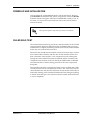
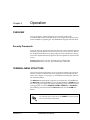
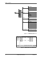
VCOM Module
User Manual
Part Numbers
1200312L5
1200312L1
1200312L2
1200312L3
61200312L1-1C
April 2000
4 Channels
8 Channels
16 Channels
24 Channels
901 Explorer Boulevard
P.O. Box 140000
Huntsville, AL 35814-4000
(256) 963-8000
© 2000 ADTRAN, Inc.
All Rights Reserved.
Printed in U.S.A.
Federal Communications Commission Radio Frequency Interference Statement
This equipment has been tested and found to comply with the limits for a Class A digital device, pursuant to Part 15 of the FCC Rules. These limits are designed to provide reasonable protection against
harmful interference when the equipment is operated in a commercial environment. This equipment
generates, uses, and can radiate radio frequency energy and, if not installed and used in accordance
with the instruction manual, may cause harmful interference to radio frequencies. Operation of this
equipment in a residential area is likely to cause harmful interference in which case the user will be
required to correct the interference at his own expense.
Change or modifications to this unit not expressly approved by the party responsible for compliance
could void the user’s authority to operate the equipment.
Warranty and Customer Service
ADTRAN will replace or repair this product within five years from the date of shipment if the product
does not meet its published specification, or if it fails while in service. For detailed warranty, repair,
and return information, refer to the ADTRAN Equipment Warranty and Repair and Return Policy. For
service, RMA requests, or more information, see the last page of this manual for a toll-free contact
number.
A return material authorization (RMA) is required prior to returning equipment to ADTRAN.
iii
Limited Product Warranty
ADTRAN warrants that for five (5) years from the date of shipment to Customer, all products manufactured by ADTRAN will be free from defects in materials and workmanship. ADTRAN also warrants
that products will conform to the applicable specifications and drawings for such products, as contained in the Product Manual or in ADTRAN's internal specifications and drawings for such products
(which may or may not be reflected in the Product Manual). This warranty only applies if Customer
gives ADTRAN written notice of defects during the warranty period. Upon such notice, ADTRAN will,
at its option, either repair or replace the defective item. If ADTRAN is unable, in a reasonable time, to
repair or replace any equipment to a condition as warranted, Customer is entitled to a full refund of the
purchase price upon return of the equipment to ADTRAN. This warranty applies only to the original
purchaser and is not transferable without ADTRAN's express written permission. This warranty becomes null and void if Customer modifies or alters the equipment in any way, other than as specifically
authorized by ADTRAN.
EXCEPT FOR THE LIMITEDWARRANTY DESCRIBED ABOVE, THE FOREGOING CONSTITUTES
THE SOLE AND EXCLUSIVE REMEDY OF THE CUSTOMER AND THE EXCLUSIVE LIABILITY OF
ADTRAN AND IS IN LIEU OF ANY AND ALL OTHER WARRANTIES (EXPRESSED OR IMPLIED).
ADTRAN SPECIFICALLY DISCLAIMS ALL OTHER WARRANTIES, INCLUDING (WITHOUT LIMITATION), ALL WARRANTIES OF MERCHANTABILITY AND FITNESS FOR A PARTICULAR PURPOSE. SOME STATES DO NOT ALLOW THE EXCLUSION OF IMPLIEDWARRANTIES, SO THIS
EXCLUSION MAY NOT APPLY TO CUSTOMER.
In no event will ADTRAN or its suppliers be liable to Customer for any incidental, special, punitive,
exemplary or consequential damages experienced by either Customer or a third party (including, but
not limited to, loss of data or information, loss of profits, or loss of use). ADTRAN is not liable for damages for any cause whatsoever (whether based in contract, tort, or otherwise) in excess of the amount
paid for the item. Some states do not allow the limitation or exclusion of liability for incidental or consequential damages, so the above limitation or exclusion may not apply to Customer.
iv
Table of Contents
List of Figures ...................................................................................................................................................vii
Chapter 1 Introduction ................................................................................................................................ 1-1
Voice Compression Module Overview ......................................................................................................... 1-1
Functional Description .................................................................................................................................... 1-1
Voice Compression Resources ....................................................................................................................... 1-1
Physical Description ........................................................................................................................................ 1-2
Related Documentation ................................................................................................................................... 1-2
Chapter 2 Installation .................................................................................................................................. 2-1
Unpack and Inspect ......................................................................................................................................... 2-1
Contents of Adtran Shipment ........................................................................................................................ 2-1
Installing the VCOM Module ......................................................................................................................... 2-1
Power-up and Initialization ............................................................................................................................ 2-3
Failed Self-test ................................................................................................................................................... 2-3
Chapter 3 Operation .................................................................................................................................... 3-1
Overview ........................................................................................................................................................... 3-1
Security Passwords ................................................................................................................................... 3-1
Terminal Menu Structure ................................................................................................................................ 3-1
Menu Access ..................................................................................................................................................... 3-3
Modules ...................................................................................................................................................... 3-3
Slt ................................................................................................................................................................. 3-3
Type ............................................................................................................................................................ 3-3
Menu ........................................................................................................................................................... 3-3
Alarm .......................................................................................................................................................... 3-3
Test .............................................................................................................................................................. 3-3
State ............................................................................................................................................................. 3-4
Status .......................................................................................................................................................... 3-4
Online .................................................................................................................................................. 3-4
No Response ....................................................................................................................................... 3-4
Empty .................................................................................................................................................. 3-4
Offline .................................................................................................................................................. 3-4
Offline / No Response ...................................................................................................................... 3-4
Not Ready ........................................................................................................................................... 3-4
Rev .............................................................................................................................................................. 3-4
VCOM Menus ................................................................................................................................................... 3-5
Info .............................................................................................................................................................. 3-5
Part Number .............................................................................................................................................. 3-5
Serial Number ........................................................................................................................................... 3-5
Assembly Revision ................................................................................................................................... 3-5
Firmware Revision .................................................................................................................................... 3-5
Status .......................................................................................................................................................... 3-5
61200312L1-1
VCOM Module User Manual
v
Table of Contents
Device ......................................................................................................................................................... 3-5
State ............................................................................................................................................................. 3-5
N/A ..................................................................................................................................................... 3-5
Available .............................................................................................................................................. 3-6
Busy ...................................................................................................................................................... 3-6
Testing .................................................................................................................................................. 3-6
Failed ................................................................................................................................................... 3-6
Algorithm ................................................................................................................................................... 3-6
N/A ..................................................................................................................................................... 3-6
G.723.1 ................................................................................................................................................. 3-6
Netcoder .............................................................................................................................................. 3-6
Silence ......................................................................................................................................................... 3-6
Connection ................................................................................................................................................. 3-6
Frame Type ................................................................................................................................................ 3-7
Blank .................................................................................................................................................... 3-7
DTMF ................................................................................................................................................... 3-7
Voice ..................................................................................................................................................... 3-7
2100Hz tone ........................................................................................................................................ 3-7
V.21 ....................................................................................................................................................... 3-7
V.27ter (2400 bps) ............................................................................................................................... 3-7
V.27ter (4800 bps) ............................................................................................................................... 3-7
V.29 (7200 bps) .................................................................................................................................... 3-7
V.29 (9600 bps) .................................................................................................................................... 3-7
V.33 (12000 bps) .................................................................................................................................. 3-7
V.33 (14400 bps) .................................................................................................................................. 3-7
Config ......................................................................................................................................................... 3-8
Device ......................................................................................................................................................... 3-8
State ............................................................................................................................................................. 3-8
Deferred ............................................................................................................................................... 3-8
Available .............................................................................................................................................. 3-8
Disabled ............................................................................................................................................... 3-8
TEST ............................................................................................................................................................ 3-8
Device ......................................................................................................................................................... 3-8
Usage Time ................................................................................................................................................ 3-9
ATLAS Frms .............................................................................................................................................. 3-9
ATLAS Drop .............................................................................................................................................. 3-9
VCOM Frms ............................................................................................................................................... 3-9
VCOM Drop ............................................................................................................................................. 3-10
Clear .......................................................................................................................................................... 3-10
Reloads ..................................................................................................................................................... 3-10
FAX Capability ........................................................................................................................................ 3-10
Enable/Disable FAX Capability ........................................................................................................... 3-10
Current FAX Status ................................................................................................................................. 3-10
ATLAS Features used with VCOM Modules ............................................................................................. 3-11
Factory Restore ........................................................................................................................................ 3-11
System Self-Test ...................................................................................................................................... 3-11
Index ..........................................................................................................................................................Index-1
vi
VCOM Module User Manual
61200312L1-1
List of Figures
Figure 2-1.
Figure 3-1.
Figure 3-2.
Figure 3-3.
VCOM Rear Chassis.................................................................................................................... 2-2
VCOM Module Menu Tree ........................................................................................................ 3-2
Modules Menu with VCOM Installed...................................................................................... 3-2
VCOM Menus .............................................................................................................................. 3-5
61200312L1-1
VCOM Module User Manual
vii
List of Figures
viii
VCOM Module User Manual
61200312L1-1
Chapter 1
Introduction
VOICE COMPRESSION MODULE OVERVIEW
The Voice Compression Module (VCOM Module) combines with other
ATLAS 550 components to implement a voice over frame relay (VoFR)
capability in the ATLAS 550 series of Integrated Access Systems. You can
order the VCOM Module with support for 4, 8, 16, 24, or 30 simultaneously
compressed calls.
FUNCTIONAL DESCRIPTION
The VCOM Module installs onto any option module that can be installed in
the ATLAS 550 chassis. You can view the module status from the ATLAS 550
front panel LEDs (also see Chapter 4 of the ATLAS 550 User Manual). You can
also use the terminal menus to provide additional status information,
configure the module, and download application software. Access the
terminal menus via either a VT-100 terminal connected to the ATLAS 550
Base Unit's control port or a Telnet session established through the Base
Unit's Ethernet port.
VOICE COMPRESSION RESOURCES
61200312L1-1
•
The VCOM Module ordering options provide 4, 8, 16, 24, or 30 voice
compression resources.
•
The VCOM Module provides automatic selection of CCITT Standard or
ADTRAN-proprietary voice compression algorithms based on endpoint
configuration.
•
The VCOM Module supports FAX at 14400 bps.
•
The VCOM Module includes dual-tone, multi-frequency (DTMF) generation and detection.
•
The VCOM Module enables and disables individual voice compression
resources.
VCOM Module User Manual
1-1
Chapter 1. Introduction
PHYSICAL DESCRIPTION
The VCOM Module provides no external interfaces. Other ATLAS 550
components provide both the network and customer interfaces. An internal
bus exchanges information between the ATLAS 550 chassis and the
VCOM Module.
RELATED DOCUMENTATION
The following document contains additional information about the
ATLAS 550 frame relay feature:
•
1-2
ATLAS 550 User Manual (P/N 61200305L1-1)
VCOM Module User Manual
61200312L1-1
Chapter 2
Installation
UNPACK AND INSPECT
Carefully inspect the VCOM Module for shipping damages. If you suspect
damage, file a claim immediately with the carrier and then contact
ADTRAN Technical Support. If possible, keep the original shipping
container for returning the VCOM Module for repair or for verification of
shipping damage.
CONTENTS OF ADTRAN SHIPMENT
The ADTRAN shipment includes the following items:
•
VCOM Module
•
VCOM Module User Manual
(Insert into main ATLAS 550 User Manual.)
INSTALLING THE VCOM MODULE
The VCOM resource module must be attached to an ATLAS 550 option module before the VCOM resource module may be installed into the ATLAS 550
unit.
The VCOM resource module cannot be installed into an
ATLAS 550 chassis without being first attached to an ATLAS 550
option module.
The VCOM resource module can be attached to any type of ATLAS 550
option module and the resulting assembly can then be installed into any
option module slot of the ATLAS 550 chassis. Only an ATLAS 550 option
module can be used to carry the VCOM resource module. In particular, the
VCOM resource module cannot be attached to any network module or
inserted into any network module slot of the ATLAS 550 chassis.
To install the VCOM resource module onto an ATLAS 550 option module
and then into the ATLAS 550 unit, use the following procedure.
61200312L1-1
VCOM Module User Manual
2-1
Chapter 2. Installation
Instructions for Installing the VCOM Module
Step
1
Action
On the rear of the ATLAS 550 chassis, remove the cover plate
covering the slot into which the option module carrying the VCOM
resource module is to be inserted.
If theATLAS 550 option module is already in the ATLAS 550
chassis, simply loosen the thumbscrews at both edges of the
option module faceplate and slide the module out of the chassis.
Carefully align the P10 connector on the VCOM resource module
with the J10 connector on the option module.
2
Using only fingertip pressure, so that neither circuit board bends
or flexes, ensure that the connectors are firmly seated.
Secure the opposite end of the VCOM resource module to the
option module using the screws and standoff posts supplied.
3
Slide the option module, with the VCOM resource module
attached, into the ATLAS 550 chassis until the module is
positioned firmly against the front of the ATLAS unit.
4
Fasten the thumbscrews at both edges of the option module
faceplate. Tighten with a screwdriver.
5
Install any additional modules into the base unit, as specified in
the Installation chapter of the ATLAS 550 User Manual.
Figure 2-1 shows the proper placement of the VCOM Module in the
ATLAS 550 chassis.
VCOM Module
Remove Cover Plate
1
O
O I
4
ALL EMPTY SLOTS MUST BE
COVERED WITH BLANK PANELS
NETWORK 2
FUSE RATING: 2A/250V SLO-BLO
ETHERNET
CONTROL
IN
OUT
RELAY
MON
CAUTION: FOR CONTINUED PROTECTION
AGAINST RISK OF FIRE, REPLACE ONLY
WITH SAME TYPE AND RATING OF FUSE.
2
DUAL T1 / PRI
MON
500 Series
2
I
90-240VAC, 2A, 50/60Hz
ALARM
Option
Module
NC NO COM GND
Figure 2-1. VCOM Rear Chassis
Option modules are intended to be serviced by qualified service
personnel only.
2-2
VCOM Module User Manual
61200312L1-1
Chapter 2. Installation
POWER-UP AND INITIALIZATION
After installing the VCOM Module into the ATLAS 550 chassis, the front
panel STATUS indicator blinks red, yellow, and green for a time. The STATUS
indicator remains solid green when the VCOM Module is ready to use. At
this time, you can invoke a system self-test; refer to the ATLAS 550 User
Manual for details.
This self-test sequence may take up to eleven (11) minutes.
FAILED SELF-TEST
The terminal menu self-test log records any self-test failures for the VCOM
resource module. Resources that fail self-test are disabled after power-up
initialization is complete. Performing a hardware-level reset via the terminal
menu may recover these failed resources.
Self-test for the VCOM resource module consists of two basic steps: verification of the module’s interface with the ATLAS 550 controller chassis and
then verification of the module’s voice compression resource data paths.
During tests of the interface between the module and the controller, both
components exercise their circuits for the DUAL-PORT RAM, or DPRAM.
Once this interface is verified, testing proceeds to the voice compression
data paths.
The controller generates a special data stream, known as QRSS, that is individually sent to each voice compression resource. The voice resource must
return the data error-free; the error-detection circuits are then checked by intentionally inserting an error that must be detected. This testing may take up
to almost 30 seconds per voice resource and once started, must be allowed
to run to completion.
61200312L1-1
VCOM Module User Manual
2-3
Chapter 2. Installation
2-4
VCOM Module User Manual
61200312L1-1
Chapter 3
Operation
OVERVIEW
You can configure, control, diagnose, and view the status of the
VCOM Module with the terminal menus. This chapter describes the menu
items available for operating the VCOM Module using the terminal menu.
Security Passwords
You must have the appropriate password level to use the terminal menu to
edit items. (See the section Access Passwords in the ATLAS 550 User Manual
for detailed information on working with passwords.) Each menu description in this chapter indicates the password levels required for read and write
access.
Security level 1 users can view and edit every available field.
Security level 5 users can view any field but they cannot edit.
TERMINAL MENU STRUCTURE
ATLAS uses a hierarchical menu to access all of its features. The top-most
menu level leads to submenus that are grouped by functionality (see the
menu tree in Figure 3-1 on page 3-2). All submenu items display in the VT100 terminal window.
The MODULES terminal menu configures and controls the VCOM Module.
The MODULES submenu, TYPE, shows the VCOM Module as VCOM (see Figure 3-2 on page 3-2). (This will change, depending on the number of channels supported. It could be VCOM-4, VCOM-8, VCOM-16, or VCOM-24.)
The following sections describe the MODULES menu and its VCOM submenus.
For simplicity, future references to the VCOM in this manual will
not carry the channel designation.
61200312L1-1
VCOM Module User Manual
3-1
Chapter 3. Operation
Part Number
Serial Number
Assembly Revision
Firmware Revision
Info
Modules
Slt
Type
Menu
Alarm
Test
State
Status
Rev
Status
Config
Device
State
Algorithm
Silence
Connection
Frame Type
Device
State
Device
Usage Time
ATLAS Frms
ATLAS Drop
VCOM Frms
VCOM Drop
Clear
Reloads
Test
FAX capablility
Enable/Disable FAX capability
Current FAX status
Figure 3-1. VCOM Module Menu Tree
Figure 3-2. Modules Menu with VCOM Installed
3-2
VCOM Module User Manual
61200312L1-1
Chapter 3. Operation
MENU ACCESS
The ATLAS 550 system controller automatically detects the presence of the
VCOM Module as it is installed into the system. To access the VCOM
MODULE menus and submenus, use the keyboard arrow keys to scroll to the
appropriate row and column; then, press Enter on the keyboard.
Refer to the ATLAS 550 User Manual for detailed instructions on
navigating through the terminal menus.
MODULES
The following paragraphs describe the MODULES menus of the ATLAS 550.
SLT
Read Security: 5
Displays the number of available slots in the ATLAS 550 chassis. SLOT 0
refers to the ATLAS 550 Base Unit.
TYPE
Write Security: 3; Read Security: 5
Displays the module type currently installed in the slot or the module type
you plan to install in the slot. If a VCO MModule is installed, the TYPE field
automatically defaults to VCOM (the VCOM Module). Alternatively, you
can use this field to preconfigure the system before installing a module by
specifying the module type that will be installed into each slot.
If a module is installed, TYPE automatically displays the name of
the installed module. To change this name, set TYPE to EMPTY and
then select another module.
MENU
Read Security: 5
Displays additional status and configuration menus and submenus for various modules. To access the VCOM Module (VCOM), use the arrow keys to
scroll over to the MENU column and down to VCOM; then press Enter. (A
discussion of the submenu items for this option begins with VCOM Menus
on page 3-5.)
ALARM
Read Security: 5
Indicates any alarm conditions on the VCOM Module. Press Enter in this
field to open the ALARM menu.
TEST
Read Security: 5
Indicates when the VCOM Module is executing a test. Press Enter in this
field to open the TEST menu.
61200312L1-1
VCOM Module User Manual
3-3
Chapter 3. Operation
STATE
Read Security: 5
Denotes the module as ONLINE or OFFLINE. Even though a module is physically installed, it must be marked ONLINE for it to be considered an available
resource.
Marking an installed module OFFLINE may be useful during system troubleshooting. If you choose OFFLINE, the module will not be in an alarm condition, but will display OFFLINE.
Only if STATE reads ONLINE can the ATLAS use an installed
module for any data movement.
STATUS
REV
3-4
Read Security: 5
Displays status information on the VCOM Module.
ONLINE
The module is enabled and is responding to the system controller's status
polls. This is the normal response of the system.
NO RESPONSE
The module is enabled but it is not responding to the system controller's status polls. This response indicates a problem in the system. It also shows if
the module is not installed.
EMPTY
The system controller has neither detected any module in the option slot, nor
has a module been manually enabled for this slot.
OFFLINE
The module is installed but has been manually changed to OFFLINE by a user.
The module is still responding to the system controller status polls.
OFFLINE /
NO RESPONSE
The module is installed but has been manually changed to OFFLINE by a user.
The module is not responding to the system controller's status polls. This response indicates a problem in the system. It also shows when the module is
not installed.
NOT READY
The module is installed and performing startup initialization. The initialization of the VCOM Module should take less than two minutes.
Read Security: 5
Displays the assembly revision level of the selected module.
VCOM Module User Manual
61200312L1-1
Chapter 3. Operation
VCOM MENUS
Figure 3-3 shows the MENUS for the VCOM Module. The following sections
describe these options.
Figure 3-3. VCOM Menus
INFO
Read Security: 5
Displays module and software information for the VCOM module.
PART NUMBER
Read Security: 5
Displays the ADTRAN part number for the module (read-only).
SERIAL NUMBER
Read Security: 5
Displays the VCOM Module's serial number.
ASSEMBLY REVISION Read Security: 5
Displays the assembly revision level for the VCOM Module (read-only).
FIRMWARE REVISION Read Security: 5
Displays the firmware revision level for the VCOM Module (read-only).
STATUS
Displays submenus for available resources of the VCOM Module.
DEVICE
Read Security: 5
Indicates the resource number of the VoFR device listed. On the
VCOM Module, VoFR devices are numbered 1-32.
STATE
Read Security: 5
Indicates the condition of the individual VoFR device.
N/A
61200312L1-1
Not available. This device is not populated on the VCOM Module.
VCOM Module User Manual
3-5
Chapter 3. Operation
AVAILABLE
This resource is available for use as a voice compression resource.
BUSY
This resource is currently being used as a voice compression resource.
TESTING
This resource is currently being tested and is not available for use.
FAILED
This resource has failed testing and is not available for use.
ALGORITHM
Read Security: 5
Denotes the voice compression algorithm being used by the VoFR device.
Any VoFR device can use any available compression algorithm. When
ATLAS 550 chooses a VoFR device for a particular call, the voice compression algorithm is set to match the dial plan endpoint configuration. Refer to
the Frame Relay section of the ATLAS 550 User Manual for more information.
N/A
Not available. This device has not been assigned a voice compression algorithm.
G.723.1
CCITT G.723.1 compression; 6.3 kbps bandwidth.
NETCODER
ADTRAN-proprietary NETCODER compression; 6.4 kbps bandwidth.
Some voice compression standards are proprietary and may be
used only under specific licensing arrangements. The ATLAS 550
provides complete management of these licensed resources;
therefore, users are not required to take additional steps to ensure
conformance with licensing provisions. For example, the ATLAS
550 manages its resources so users never exceed the maximum
licensed number of simultaneous connections. Refer to the Frame
Relay section of the ATLAS 550 User Manual for details.
SILENCE
Read Security: 5
Reduces total system bandwidth load.
Voice endpoints continue to originate frame relay traffic during periods of
relative silence. The VCOM Module expects to receive such silence frames;
therefore, silence compression is DISABLED by default. Some voice endpoints can be configured so that no silence frames are transmitted during
periods of relative silence. For compatibility with these devices, the
VCOM Module can be configured to expect that silence suppression is
ENABLED; thus, no frame relay traffic is generated during periods of silence.
Both voice endpoints must agree on the silence suppression setting. Refer to
the ATLAS 550 User Manual for more information.
CONNECTION
3-6
Read Security: 5
Helps identify a suspect VoFR device if a particular call reports poor quality. The displayed packet identifier and the dial plan endpoint identify the
call using this VoFR device.
VCOM Module User Manual
61200312L1-1
Chapter 3. Operation
FRAME TYPE
Read Security: 5
Displays the kind of frame the ATLAS 550 receives from the frame relay
endpoint connected to the VCOM channel, allowing users to monitor the
kind of data being carried on the network and processed by the ATLAS 550.
(The ATLAS 550 interprets the most-recently received frame from the endpoint.)
During a voice connection, the frame type displays as VOICE. For a FAX connection, a variety of frame types display. Initially, VOICE displays indicating
that although the call has completed, the answering FAX machine has not
yet announced its 2100 HZ tone. After completing the 2100 Hz, both FAX
endpoints repeat a V.21 and V.xx cycle for each page of the FAX document.
Each packet the VCOM Module receives from its connected frame relay endpoint is classified into one of the following groups:
BLANK
No frame has yet been received from the endpoint, or a FAX connection is
between protocol states.
DTMF
Dual-tone, multi frequency (DTMF) digit received.
VOICE
Receiving voice frames. A connection to a FAX endpoint shows a VOICE status until the FAX protocol is established.
2100HZ TONE
FAX single-frequency tone detected indicating the beginning of a FAX session.
V.21
FAX single-frequency tone detected indicating the beginning of a FAX page.
V.27TER
(2400 BPS)
FAX data reception of 2400 bps using protocol V.27ter.
V.27TER
(4800 BPS)
FAX data reception of 4800 bps using protocol V.27ter.
V.29 (7200 BPS)
FAX data reception of 7200 bps using protocol V.29.
V.29 (9600 BPS)
FAX data reception of 9600 bps using protocol V.29.
V.33
(12000 BPS)
FAX data reception of 12000 bps using protocol V.33.
V.33
(14400 BPS)
FAX data reception of 14400 bps using protocol V.33.
61200312L1-1
VCOM Module User Manual
3-7
Chapter 3. Operation
CONFIG
Provides diagnostic tools for suspected problems; under normal operation,
users do not configure the VoFR devices.
DEVICE
Read Security: 5
Identifies the VoFR device on the VCOM Module. VoFR devices are numbered 1 through 32.
STATE
Write Security: 3; Read Security: 5
Controls the configuration state of the individual VoFR device. The
VCOM Module determines the initial configuration state of each device.
ATLAS uses this configuration information to determine which VoFR
devices are functional and may be used; which are defective and should not
be used; or which are not present on the module and should not be used.
Users who suspect an individual VoFR device of improper operation can
manually disable that device to prevent ATLAS from attempting to use it.
The possible states are defined below.
DEFERRED
Devices which fail built-in testing are automatically marked as Deferred, indicating that the ATLAS 550 declines to use the device.
AVAILABLE
The device is properly functioning and can be used when required. The
ATLAS 550 automatically marks devices that pass built-in testing as Available.
DISABLED
Marking a device as Disabled prevents the ATLAS 550 from attempting to
use it. You can mark a device currently in use as disabled without disturbing
the connection, but the device will not be eligible for use in future calls until
you re-mark it as Available. You might want to do this if you suspect that a
particular device is malfunctioning and do not want any calls routed to it.
TEST
The TEST menu requires no user action during normal operation. However,
the ATLAS 550 and the VCOM Module make various TEST performance
measurements available to the user to gain insight into the low-level functioning of the VCOM Module. If a malfunction is suspected on the VCOM
module, ADTRAN service personnel can use this menu to locate the problem.
This menu is documented here in the interest of completeness. The values
automatically reset each time the VCOM Module is installed into the the
ATLAS 550 chassis. These values are also cleared whenever the ATLAS
controller is rebooted.
DEVICE
3-8
Read Security: 5
Identifies the VoFR device.
VCOM Module User Manual
61200312L1-1
Chapter 3. Operation
USAGE TIME
Read Security: 5
Measures the total elapsed time that a VoFR device has the status BUSY.
The time is expressed with millisecond precision. Available VoFR devices
are assigned new connections using a round-robin technique where all
other available VoFR devices must be used before a given device is assigned
a new connection. This scheme tends to use allVoFR devices evenly. If a
given device shows significantly less elapsed usage time than other VoFR
devices on the same VCOM Module, that device may be faulty.
ATLAS FRMS
Read Security: 5
(ATLAS Frames) Counts every frame that theATLAS 550 sends to or
receives from the VoFR device. This count indicates activity but does not
indicate the actual amount of frame relay data exchanged. The total number
of frames handled by theVoFR device is given by the following equation:
Frames ATLASTotal = FramesATLAS + Frames ATLASDropped
See the ATLAS DROP definition below for a description of the term:
Frames ATLASDropped
ATLAS DROP
Read Security: 5
Counter-measures each frame that is dropped or discarded during communication between the the ATLAS 550 and the VoFR device; i.e., ATLAS
Frames Dropped. The exchange protocol is designed so that no frames
should be discarded during this operation. A consistent pattern of dropped
frames by a given VoFR device may indicate a faulty VoFR device or an
overloaded ATLAS 550 system.
The discarded frame indicated by this value does not reflect
network-level performance management, but indicates an
anomalous condition within the ATLAS 550 unit. Persistently
dropped frames may indicate a problem with the ATLAS 550 unit
or the VCOM Module.
VCOM FRMS
Read Security: 5
Counts every frame successfully sent to or received from theATLAS 550
system controller. This is an indication of activity but does not indicate the
actual amount of frame relay data exchanged. The following equation gives
the total number of frames handled for this VoFR device by the
VCOM Module:
Frames VCOMTotal = Frames VCOM + Frames VCOMDropped
See the VCOM DROP definition below for a description of the term:
FramesVCOMDropped
61200312L1-1
VCOM Module User Manual
3-9
Chapter 3. Operation
VCOM DROP
Read Security: 5
Counter-measures each frame dropped or discarded by VCOM Module
during communication with the ATLAS 550 system controller about a VoFR
device. The exchange protocol is designed so that no frames should be discarded during this operation. A consistent pattern of dropped frames by a
given VoFR device may indicate a faulty VoFR device or an overloaded
ATLAS 550 system.
The discarded frame indicated by this value does not reflect
network-level performance management but indicates an
anomalous condition within the ATLAS 550 unit. Persistently
dropped frames may indicate a problem with the ATLAS 550 unit
or the VCOM module.
CLEAR
Read Security: 5; Write Security: 3
Resets the elapsed usage time and frame counters for thisVoFR device.
Ordinarily, users won’t reset these performance measurements. However,
this feature can be useful when testing that a suspected problem has been
resolved and when zeroing the various counters would make observing
future events easier.
Resetting these performance counters has no effect on the
performance values accessible via the SNMP network management
interface.
RELOADS
Read Security: 5
Number of times since reboot that this device has been reloaded due to a
failure.
FAX CAPABILITY
The FAX Capability menu allows FAX transmissions to be enabled/disabled.
ENABLE/DISABLE
FAX CAPABILITY
This menu item toggles FAX capability on and off.
CURRENT FAX
STATUS
Displays current state of FAX capability.
3-10
VCOM Module User Manual
61200312L1-1
Chapter 3. Operation
ATLAS FEATURES USED WITH VCOM MODULES
In addition to the VCOM menu items, the ATLAS 550 system provides
additional services that operate in conjunction with the VCOM Module:
FACTORY RESTORE and SYSTEM SELF-TEST.
FACTORY
RESTORE
The factory default settings for the VCOM Module can be restored from the
terminal menus.
To restore all of the factory default settings for the VCOM Module, press the
F key while the terminal cursor is positioned over the SLT (Slot) number on
the MODULES menu.
To restore the factory default setting for only a single field, press the F key
while the terminal cursor is positioned over that particular field.
SYSTEM
SELF-TEST
SYSTEM SELF-TEST, a submenu of the ATLAS main menu item SYSTEM
UTILITY, executes both the VCOM Module internal test and the ATLAS 550
internal test. For additional information on self-test, see the ATLAS 550 User
Manual.
To execute the test, when SYSTEM SELF-TEST displays, place the cursor on it
and press Enter. The unit continuously changes the display on the self-test
log screen until all test results are shown.
61200312L1-1
VCOM Module User Manual
3-11
Chapter 3. Operation
3-12
VCOM Module User Manual
61200312L1-1
Index
RMA iii
A
accessing menus 3-3
ATLAS 550 menus and submenus
Factory Restore 3-11
Modules 3-3
Alarm 3-3
Menu 3-3
Rev 3-4
Slt 3-3
State 3-4
Status 3-4
Empty 3-4
No Response 3-4
Not Ready 3-4
Offline 3-4
Online 3-4
Test 3-3
Type 3-3
System Self-test 3-11
S
self-test
failed 2-3
service iii
shipping
contents 2-1
damage 2-1
V
F
FCC statement iii
I
initializing the module 2-3
installing the VCOM module 2-1
L
limited product warranty iv
M
menu structure 3-1
menu tree 3-2
moving through menus 3-3
P
password levels 3-1
R
return material authorization (RMA) iii
61200312L1-1
VCOM menus and submenus 3-5
Config 3-8
Device 3-8
State 3-8
State (Available) 3-8
State (Deferred) 3-8
State (Disabled) 3-8
FAX capability 3-10
Current FAX status 3-10
Enable/Disable FAX capability 3-10
Info 3-5
Assembly Revision 3-5
Firmware Revision 3-5
Part Number 3-5
Serial Number 3-5
Status 3-5
Algorithm 3-6
Algorithm (G.723.1) 3-6
Algorithm (N/A) 3-6
Algorithm (Netcoder) 3-6
Connection 3-6
Device 3-5
Frame Type 3-7
Frame Type, 2100Hz tone 3-7
Frame Type, DTMF 3-7
Frame Type, V.21 3-7
Frame Type, V.27ter (2400 bps) 3-7
Frame Type, V.27ter (4800 bps) 3-7
Frame Type, V.29 (7200 bps) 3-7
Frame Type, V.29 (9600 bps) 3-7
Frame Type, V.33 (12000 bps) 3-7
Frame Type, V.33 (14400 bps) 3-7
Frame Type, Voice 3-7
Silence 3-6
State 3-5
State (Available) 3-6
VCOM Module User Manual
Index-1
Index
State (Busy) 3-6
State (Failed) 3-6
State (N/A) 3-5
State (Testing) 3-6
StatusFrame Type, Blank 3-7
Test 3-8
ATLAS Drop 3-9
ATLAS Frms 3-9
Clear 3-10
Device 3-8
Index-2
Reloads 3-10
Usage Time 3-9
VCOM Drop 3-10
VCOM Frms 3-9
VoFR capability 1-1
W
warranty iii
VCOM Module User Manual
61200312L1-1
Product Support Information
Pre-sales Inquiries and Applications Support
Please contact your local distributor, ADTRAN Applications Engineering, or ADTRAN Sales:
Applications Engineering
(800) 615-1176
Sales
(800) 827-0807
Post-Sales Support
Please contact your local distributor first. If your local distributor cannot help, please contact
ADTRAN Technical Support and have the unit serial number available.
Technical Support
(888) 4ADTRAN
Repair and Return
If ADTRAN Technical Support determines that a repair is needed, Technical Support will coordinate
with the Customer and Product Service (CAPS) department to issue an RMA number. For information regarding equipment currently in house or possible fees associated with repair, contact CAPS
directly at the following number:
CAPS Department
(256) 963-8722
Identify the RMA number clearly on the package (below address), and return to the following address:
ADTRAN Customer and Product Service
6767 Old Madison Pike
Progress Center
Building #6 Suite 690
Huntsville, Alabama 35807
RMA # __________________