1
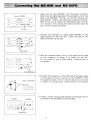
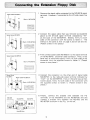
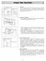
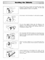
INSTRUCTION MANUAL Note for Users in U K IMPORTANT The wires in the mains lead of this apparatus are coloured in accordance with the following code: BLUE: BROWN: Neutral Live As the colours of the wires in the mains lead of this apparatus may not correspond with the coloured markings identifying the terminals in your plug, proceed as follows: * The wire which is coloured B LU E must be connected to the terminal which is marked with the letter N or coloured BLACK. * The wire which is coloured BROWN must be connected to the terminal which is marked with the letter L or coloured RED. INTRODUCTION Thank you for purchasing the SHARP Floppy Disk MZ-80FB/FBK. It is a peripheral for use with the SHARP Personal Computer MZ-80B which can operate a maximum of 4 drives. We believe that it will be very useful as an external memory unit because of its large capacity and high speed access. Read this instruction manual carefully before using the Floppy Disk so you can use it correctly. Page • • • • • • • • Floppy Disk MZ-80FB ...................................... Connecting the MZ-80B and MZ-80FB .......................... Extension Floppy Disk MZ-80FBK ............................. Connecting the Extension Floppy Disk .......................... Floppy Disk Operation ...................................... Handling the Diskette ....................................... Cautions. . . . . . . . . . . . . . . . . . . . . . . . . . . . . . . . . . . . . . . . . . . . . . . .. Specifications . . . . . . . . . . . . . . . . . . . . . . . . . . . . . . . . . . . . . . . . . . . .. 2 3 4 5 6 7 8 9 Floppy Disk MZ-80FB L Disk Drive Comes with 2 drives (upper, lower). 4 ...... 5."- - -ill 2~ SHARP - --, -r---- ~ 2 3 [J] I @ I I 3 4 I~ -, 6 5 6 7 IN = = = = = = = = = = = = == 7 S S -II----=~-- Appliance Inlet Connect the supplied power cord here. 10 FG Terminal Connect the supplied braided wire to this terminal. 11 Rating Name Plate Use a power supply with the voltage shown here. 12 Braided Wire (Accessory) Connect this wire to the FG terminal, using it to connect the cabinets. 10 9----' Power Indicator Lights up when the power is ON. Signal Terminal Connect the connector of the signal cable (option) to this terminal. Power Switch Push this switch toward "I" to turn on the power. 9 11 10 Front Door Comes with an anti-crunch mechanism to protect the diskette. Slot for Inserting Diskette Open the front door and insert the diskette here. Drive No. Match the number of the controlling drive to this number. MZ-80FB operates as drive 1 (upper) and drive 2 (lower). Action Indicator Lights up when a drive is operating. 12 13 Signal Cable MZ-80FC (Option) Use this cable to connect the Floppy Disk unit and the I/O card. 14 Screws (4) Use to fix the signal cable connectors. 15 Floppy Disk I/O Card MZ-80FI (Option) Interface card for connecting the MZ-80B and Floppy Disk. Install the extension unit MZ-80EU in the MZ-80B and insert the card. 13 P~/======jq 14 ~ ~ o DD D 0 00 00 Do 15 ODD 0 0 DOn DD ~ ~ OD U 2 I nsert the I/O card MZ-80F I into the lowest connector (No. 6) on the right-hand side of the extension unit on the back of the MZ-80B. The Fig. on the left shows a I/O card inserted. Refer to the instruction manual for the MZ80B for the correct method of inserting the card and then do it properly. First remove the screws and then insert the card. Finally replace the screws. (Back of MZ-80B) I I/O Card 2 Connect the connector of signal cable MZ-80FC to the signal terminal of the I/O card. Either the right or left cable connector can be used. 3 With the supplied screws, firmly fix the right and left sides of the connector to fasten it as shown on· the left. Do not forget to put in these screws. (Fasten screws in two places.) Fix with screws. (Back of MZ-80FB) 4 Connect the connector on the other end of the signal cable to the signal terminal in the back of the MZ-80FB. With the supplied screws, firmly fix both sides of the connector to fasten it in the same way. (Fasten screws in two places.) Fix with screws. ~-~===----------====== =-----==------=---~-= c_= =-=--------=--_---=--=-= =---=-::.-----==---== =-=--==-~---====== MZ-80B MZ-80FB 5 Finally, connect the supplied braided wire between the FG terminals of the MZ-80FB and the MZ-80B. Braided Wire 3 CD Disk Drive Comes with 2 drives (upper, lower). - SHARP t-fj] J) t-:l) - ---- r-<ID ,g [gJ I @ I I I~ 1-([; :l) Front Door Comes with an anti-crunch mechanism to protect the diskette. ~t Slot for inserting diskette Open the front door and insert the diskette here. ~ Drive No. Match the number of the controlling drive to this number. MZ-80FBK operates as drive 3 (upper) and drive 4 (lower). :ID Action Indicator Lights up when the drive is operating. @ Power Indicator Lights up when the power is ON. IN OUT J) Signal Terminal (IN) 00 Connect signal cable MZ-80FC here. = = = = = = :ID Signal Terminal (OUT) Connect signal cable MZ-80FCK here. = .1) Power Switch Push this switch toward "I" to turn on the power. ([,-it---/ j] Appliance Inlet 1D Connect the supplied power cord here. 1];~===:j---------" 11) FG Terminal Connect the supplied braided wire to this terminal. 1] Rating Name Plate Use a power source with the voltage shown here. 2JL~~~~~~~~LS .:L~ Braided Wire (Accessory) Connect this wire to the FG terminal, using it to connect the cabinets. L~ Signal Cable MZ-80FCK (Option) Connect the signal terminals of the MZ-80FB K and MZ-80FB with this cable. rID Screws (4) Use to fix the signal cable connectors. 1~ 141 ====q p~~/~" Note: The MZ-80FB is the standard unit and the MZ-80FB K is the extension unit. The MZ-80FB cannot be used as an extension unit nor can the MZ-80FBK be used as a standard unit. 4 Remove the signal cable connected to the MZ-80FB signal terminal. However, if connected to the I/O side, leave it as it is. Signal Cable MZ-80FC (Back of MZ-80FB) = Signal Cable MZ-80FC IN OUT liB'" of MZ-BOFBKI 2 Connect the signal cable that was removed as explained above to the left-side signal terminal indicated by "IN" on the back of the MZ-80FBK. Besides, firmly fix both sides of the connector with the screws to fasten it. This method is the same as that on page 3, section (2) and (3). (Fasten screws in two places.) @ Signal Cable MZ-80FCK (Back of MZ-80FB) Signal Cable MZ-80FC Signal Cable MZ-80FCK ! I (Back of MZ-80FBK) = MZ-80B MZ-80FBK 3 First connect signal cable MZ-80FCK to the signal terminal of the MZ-80FB. Use either cabie connector. Then, in the same way as mentioned above, firmly fix both sides of the connector with the suppl ied screws to fasten it. (Fasten screws in two places.) 4 Connect the connector on the other end of signal cable MZ-80FCK to the right-side signal terminal indicated by "OUT" on the MZ-80FBK. Then, in the same way as mentioned above, firmly fix both sides of the connector with the suppl ied screws to fasten it. (Fasten screws in two places.) 5 Finally, connect the braided wire between the FG terminals of the MZ-80FB and the MZ-80FBK and also connect a braided wire between the MZ-80B and the MZ-80FBK as shown in the Fig. on the left. MZ-80FB I 'i~ O~IL--.J 0 Braided Wire 5 r--133.3mm rD -----j Write-protection ,.notch E E Center hole M M Index hole 1 Diskette This unit uses a 5.25" mini-disk that records on both sides as the recording medium. Its external appearance is as shown on the left. It's called a diskette and is a magnetic sheet covered by a jacket. ~ ... l 0 Head window 2 Inserting a Diskette 1. Put a finger on the bottom of the front door and lightly pull this door toward you to open it. 2. With the label side up and the head window forward, insert a diskette in the slot. There is no other way to insert a diskette correctly. 3. Push the diskette lightly until it stops and close the front door. If the diskette is not inserted all the way, the front door will not close. When this happens do not force the door closed but re-insert the diskette correctly. Diskette with write-protection. ~, ~ ........ Protection seal. 3 Write-protection Notch If the write-protection notch of the diskette is covered with a seal of silver paper, etc., writing of data is forbidden. Reading, however, is possible. Some diskettes supplied by Sharp that are called Masters have this part covered with a seal. Never remove it because it prevents trouble from improper operation. Do not cover the notch of diskette that is ordinarily used for read/write operations with a seal, etc. or writing will be impossible. a 4 Data Read/Write Operation of this unit is only by ON/OFF of the power and insertion/removal of a diskette. All reading and writing of data is controlled by the host system MZ-80B. For details refer to the software manual. A maximum of 4 drives can be operated and drives are designated by the drive numbers on the front of the unit. 6 Do not touch, soil or scratch the recording surface (Head YVindow) of the diskette with your finger. This may cause improper operation or result in no operation. Do not bend or fold the diskette or it will become unusable. Do not bring magnetic things near the diskette or the contents of the diskette will be destroyed. In addition, it's dangerous to bring a diskette near machines (motors, etc.) that generate a magnetic field. Fill in the index label before pasting it on the jacket or use a soft pointed pen. If you use a ball-point pen or other hard object on a label already pasted on the jacket, the diskette will be damaged. When not using a diskette, put it in an envelope and file it away. This also prevents trouble caused by scratches and dust. ~ Envelope Storage temperature of the diskette is 4° C -50° C. Do not put it in direct sunlight or anywhere the temperature rises above 50°C. The jacket will be deformed and the diskette will be unusable. 7 Cautions (A) Installation 1. Do not install the unit in the following places. Damp places. In direct sunlight. Dusty places. Places where the temperature is very high or low. Places that vibrate. 2. Install the unit on a solid, level stand. 3. Use a power supply voltage as indicated on the rating name plate on the back of the unit. 4. Do not install the unit near machines that generate a lot of noise. Also use a separate power source for these kinds of machines. This will prevent improper operation due to noise. 5. Do not close the ventilation holes of the unit by putting things on top of it or by covering it with a cloth, etc. 6. Use only the supplied power cord. (8) Operation 1. Do not use the unit in ways not written in the instruction manual. 2. When operating this unit, be sure that all signal cable and other connections are right. page 3 and 5.) (See 3. I mmediately pull out the power cord if water or liquid or metal objects, such as needles and pins, mistakenly get into the unit. Then, completely remove these foreign objects. 8 Specifications No. of drives: Connection between drives: Recording medium: Recording: No. of tracks: Sector: Formatted capacity: Power source: Power consumption: Operating conditions: External dimensions: Weight: Accessories: Options: Dual drives/unit Da isy-cha i n system 5.25" both-sides flexible disk Both sides, double density 70 tracks Soft sectored 280 K byte/sheet (at 16 sectors/track) Local supply voltage (Use power supply voltage as shown on rating name plate). 40W (for AC 220V, 50Hz unit) 45W (for AC 240V, 50Hz unit) 4°C - 25°C 20% - 80% (Free of moisture) 205(W) x 320 (D) x 200(H)mm 7.9kg Power cord (1), Braided wire (1), Instruction manual (1) Signal cable (MZ-80FC) for MZ-80FB Signal cable (MZ-80FCK) for MZ-80FBK I/O card (MZ-80FI) for floppy disk *Specifications and design subject to change without prior notice for product improvement. In such cases, items mentioned may be partially different from the product. 9 : SHARP CORPORATION TI NSE0016PAZZ 801205-1000-K Pri nted in Japan MZ-80FB/FBK E1