1
Owner's Manual
another free manual from www.searstractormanuals.com
ICRRFTSMRN I
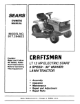
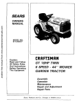
8.0 HP
30 INCH TINE WIDTH
SLEEVE HITCH
TILLER ATTACHMENT
Model No.
917.242484
CAUTION:
•
•
•
•
•
Read and follow all Safety
Rules and Instructions
before operating this
equipment.
[_
Sears,
This
from product
previously
has built
a lowengines.
emission engine
Before you
which
start
operates
the engine,
differently
read
and understandthis Owner's Manual.
Roebuck and Co., Hoffman
Visit our Craftsman
PRINTED IN U.S.A.
Safety
Assembly
Operation
Maintenance
Repair Parts
Estates,
II 60179
website:www.sears.com/craftsman
179021
3.7.01 TR
SAFETY RULES
Safe Operation
Practices
for Tiller Attachments.
TRAINING
•
o.
Read the operating and service instruction manual
carefully. Be thoroughly familiar with the controls and
the proper use of the equipment. Know how to stop the
unit and disengage the controls quickly.
Never allow children to operate the equipment. Never
allow adults to operate the equipment without proper
instruction.
•
•
•
•
another free manual from www.searstractormanuals.com
Keep the area of operation clear of all persons, particularly small children, and pets.
•
•
PREPARATION
•
•
•
•
Thoroughly inspect the area where the equipment is to
be used and remove all foreign objects.
Disengage all clutches and shift into neutral before
starting the engine (motor).
Do not operate the equipment withoutweadng adequate
outer garments. Wear footwear that will improve footing
on slippery surfaces.
Handle fuel with care; it is highly flammable.
• Use an approved fuel container.
• Never add fuel to a running engine or hot engine.
• Fillfuel tank outdoors with extreme care. Never fillfuel
tank indoors.
•
MAINTENANCE AND STORAGE
•
Keep machine, attachments, and accessories in safe
working condition.
•
Check shear bolts, engine mounting bolts, and other
bolts at frequent intervals for proper tightness to be sure
the equipment is in safe working condition.
•
Never store the machine with fuel in the fuel tank inside
a building where ignition sources are present, such as
hot water and space heaters, clothes dryers, etc. Allow
the engine to cool before storing in any enclosure.
•
Always refer to the operator's guide instructions for
important details if the tiller is to be stored for an
extended period.
• Replace gasoline cap securely and clean up spilled
fuel before restarting.
Never attempt to make any adjustments while the
engine (motor) is running (except where specifically
recommended by manufacturer).
- IMPORTANT
OPERATION
•
•
•
•
•
•
•
•
•
•
•
Do not overload the machine capacity by attempting to
till too deep at too fast a rate.
Never operate the machine at high speeds on slippery
surfaces. Look behind and use care when backing.
Lift tiller out of the ground when turning corners.
Do not put tractor in reverse gear while tiller is in the
ground.
Never allow bystanders near the unit.
Use only attachments and accessories approved by the
manufacturer of the tiller (such as wheel weights,
counterweights, cabs, etc.
Never operate the tiller without good visibility or light.
-
CAUTIONS,
IMPORTANTS,
AND NOTES ARE A MEANS
OF ATTRACTING
ATTENTION
TO IMPORTANT
OR
CRITICAL INFORMATION
IN THIS MANUAL.
Do not put hands or feet near or under rotating parts.
Exercise extreme caution when operating on or crossing
gravel drives, walks, or roads. Stay alert for hidden
hazards or traffic. Do not carry passengers.
After striking a foreign object, stop the engine (motor),
remove the wire from the spark plug, thoroughly inspect
the tiller forany damage, and repair the damage before
restarting and operating the tiller.
Exercise caution to avoid slipping or falling.
If the unit should start to vibrate abnormally, stop the
engine (motor) and check immediately for the cause.
Vibration is generally a warning of trouble.
Stop the engine (motor) when leaving the operating
position, before unclogging the tines, and when making
any repair, adjustments, and inspections.
Take all possible precautions when leavingthe machine
unattended. Disengage the power take-off, lower the
attachment, shift into neutral, stop the engine, and
remove the key.
Before cleaning, repairing, or inspecting, shut off the
engine and make certain all moving parts have stopped.
Disconnect the spark plug wire, and keep the wire away
from the plug to prevent accidental starting.
Do not run the engine indoors; exhaust fumes are
dangerous.
Never operate the tiller without proper guards, plates, or
other safety protective devices in place.
Keep children and pets away.
IMPORTANT: USED TO ALERT YOU THAT THERE ISA
POSSIBILITY OF DAMAGING THIS EQUIPMENT.
NOTE: Gives essential information that will aid you to
better understand, incorporate, or execute a particular set
of instructions.
Look for this symbol to point out important
safety precautions. It mean CAUTION!!!
BECOME ALERT!!! YOUR SAFETY IS
INVOLVED.
CAUTION: Always disconnect spark
plug wire and place wire where it cannot
contact spark plug in order to prevent
accidental starting when setting up,
transporting, adjusting or making repairs.
WARNING
The engine exhaust from this product contains chemicals known to the State of California to cause cancer, birth defects, or other
reproductive
harm.
2
another free manual from www.searstractormanuals.com
PRODUCT
SPECIFICATIONS
CUSTOMER
•
•
RESPONSIBILITIES
Read and observe the safety rules.
Followa regular schedule in maintaining, caring for and
using your tiller attachment.
Followthe instructionsinthe Customer ResponsibiliUes
and Storage sections of this Owner's Manual.
GASOLINE CAPACITY:
1 Gallon
Unleaded Regular
OIL :
(Capacity: 22 oz.)
SAE 30W (Above 32°F)
SAE 5w-30 (Below 32°F)
•
TRANSMISSION OIL :
(Capacity: 40 oz.)
SAE 30W
SPARK PLUG :
(GAP: .030")
Champion
RJ19LM or J19LM
IMPORTANT=
THIS
UNIT IS EQUIPPED
WITH AN
INTERNAL
COMBUSTION
ENGINE AND SHOULD NOT
BE USED ON OR NEAR ANY UNIMPROVED
FORESTCOVERED,
BRUSH-COVERED
OR GRASS COVERED
LAND UNLESS THE ENGINE'S
EXHAUST SYSTEM IS
EQUIPPED
WITH A SPARK
ARRESTER
MEETING
APPLICABLE
LOCAL OR STATE LAWS (IF ANY).
IF A
SPARK ARRESTER IS USED, IT SHOULD BE MAINTAINED
iN EFFECTIVE WORKING ORDER BY THE OPERATOR.
CONGRATULATIONS
on your purchase of a Sears tiller
attachment. It has been designed, engineered and manufactured to give you the best possible dependability and
performance.
IN THE STATE OF CALIFORNIA THE ABOVE IS REQUIRED
BY LAW (SECTION 4442 OF THE CALIFORNIA
PUBLIC
RESOURCES
CODE).
OTHER STATES
MAY HAVE
SIMILAR LAWS. FEDERAL LAWS APPLY ON FEDERAL
LANDS.
SEE YOUR
SEARS
SERVICE
CENTER/
DEPARTMENT
FOR SPARK ARRESTER.
(REFER TO
REPAIR PARTS SECTION OF THIS MANUAL).
Should you experience any problems you cannot easily
remedy, please contact a Sears or other qualified service
Center, which has competent, well trained technicians and
the proper tools to service or repair this unit.
Please read and retain this manual. The instructions will
enable you to assemble and maintain your tiller attachment
properly. Always observe the "SAFETY RULES".
LIMITED
ONE YEAR WARRANTY
ON CRAFTSMAN
TILLER
ATTACHMENT
For one year from date of purchase, when this tiller attachment is maintained, lubricated, and tuned up according to the
operating and maintenance instructions in the owner's manual, Sears will repair free of charge any defect in material or
workmanship.
This warranty does not cover:
•
Expendable items which become wom during normal use, such as tines, spark plugs, air cleaners and belts.
•
Repairs necessary because of operator abuse or negligence, including bent crankshafts and the failure to maintain
the equipment according to the instructions contained in the owner's manual.
•
If this Craftsman tiller attachment is used for commercial or rental purposes, this warranty applies for only 30 days
from the date of purchase.
WARRANTY SERVICE IS AVAILABLE BY RETURNING THIS CRAFTSMAN TILLER TO THE NEAREST SEARS
SERVICE CENTER/DEPARTMENT
IN THE UNITED STATES. THIS WARRANTY APPLIES ONLY WHILE THIS
PRODUCT IS IN USE IN THE UNITED STATES.
This Warranty gives you specific legal rights, and you may also have other rights which vary from state to state.
SEARS, ROEBUCK AND CO., D/817 WA, HOFFMAN ESTATES, IL 60179
TABLE OF CONTENTS
SAFETY RULES ........................................................
2
CUSTOMER RESPONSIBILITIES ....................... 3,7-9
WARRANTY ...............................................................
3
PRODUCT SPECIFICATIONS ....................................
3
ASSEMBLY ................................................................
4
OPERATION ............................................................
5-6
SERVICE & ADJUSTMENTS ................................... 10
STORAGE ................................................................
11
TROUBLESHOOTING ..............................................
12
REPAIR PARTS - TILLER ................................... 13-16
REPAIR PARTS - ENGINE .................................. 17-19
3
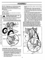
ASSEMBLY
•
When R.H., (Right Hand) or L.H. (Left Hand) are used, it
means from a position behind the steering wheel as If you
were seated on the tractor seat and facing forward.
NOTE: Remove mower deck from tractor before mounting
tiller attachment.
• . Remove tiller from carton.
LEVEL
•
Adjust stabilizer bolts so that ends are about flush with
rear of hitch bail (Fig. 2 - Inset). Leave nuts loose.
•
Lower hitch assembly and slide hitch yoke of ti!ler (Fig.
2 - Inset) over hitch tube of sleeve hitch so that the hitch
pin holes line up.
•
Insert hitch pin until it extends from bottom of hitch yoke
(Fig. 2 - Inset). Insert retainer spring into hitch pin.
•
Tighten both stabilizer bolts against the hitch yoke until
there is no looseness at the hitch point. (The frame
assembly does not swing sideways relative to the hitch
bail (Fig. 2). Be su re the frame assembly is perpendicular (square) to the centerline (direction of travel) of the
tractor. This can be determined by measuring the
distance between the edge of tine shield (Fig. 2) and the
back of
the rear tires. This distance should be the
same on the R.H. and L.H. sides within 1/2 inch.
Securely tighten the nuts on the stabilizer bolts.
NOTE: The stabilizer bolts should be loosened before
removing the tiller from the tractor. This will make it
easier to remove the hitch pin and to line up hitch pin
holes when installing another attachment. If tractor is to
be used without a rear attachment, the stabilizer bolt
should be secured by tightening the nuts (Fig. 2-Inset).
TILLER
another free manual from www.searstractormanuals.com
Place tiller on level ground so that tractor can be backed
up to it for assembly.
I
CAUTION: Tiller
performing
the following
will be step.
heavy when
Assemble sleeve hitch to tractor. See hitch Owner's
Manual.
I
I
Adjust tiller gauge wheels so that engine is level (Fig. 1).
•
Remove retainer spring from drilled rivet.
•
Remove rivet and adjust gauge wheels up or down as
required to level tiller. Replace rivet and retainer spring.
RETAINER
SPRING
M ODEL PLATE
L
,
TRANSMISSION
OIL FILL PLUG
ENGINE OIL
FILL TUBE
STABILIZER
BOLT
FIG. I
A'n'ACHING
TILLER
TO TRACTOR
Optional accessory tractorweights and/or tire chains should
be purchased to aid in the operation of this tinerattachment.
•
Install one or more wheel weights to each rear wheel to
insure good traction when operating. Tire chains can be
used in place of, or in addition to, wheel weights.
•
Install two front end weights to the front of the tractor.
This will aid steering control.
•
Check tractor tires for proper air pressure. See your
tractor's Owner's Manual.
NUT
HITCH PIN
HITCH BAIL
FiG. z
4
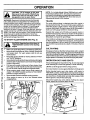
OPERATION
IMPORTANT: READ THE =RULES FOR SAFE OPERATION"
CAREFULLY
BEFORE
OPERATING
YOUR TILLER
ATTACHMENT.
CHECK
HOW TO USE YOUR TILLER
STOPPING
(See Fig. 3)
another free manual from www.searstractormanuals.com
TINES
•
Move tine clutch lever to "DISENGAGED"
position.
ENGINE
•
Move engine throttle lever to "STOP" position.
•
Never use choke to stop engine.
TO USE CHOKE
CONTROL
(See Fig.
TILLING
•
Fill fuel tank. Use fresh, clean, regular unleaded gasoline with a minimum of 87 octane. Do not mix oil with
gasoline. Purchase fuel in quantities that can be used
within 30 days to assure fuel freshness.
IMPORTANT: WHEN OPERATING IN TEMPERATURES
BELOW 32°F (0°C), USE FRESH CLEAN WINTER GRADE
GASOLINE TO HELP INSURE GOOD COLD WEATHER
STARTING.
DEPTH (See Figs. 4 & 5)
The tilling depth is controlled by the gauge wheels and to
some extent by the adjustable link sleeve. When deeper
tilling is required, the gauge wheels must be raised. Wheels
must be lowered for shallower tilling,
•
Remove retainer spring from drilled rivet. Adjust gauge
wheels up or down as desired and replace rivet and
retainer spring.
NOTE: Each hole will raise or lower gauge wheels 1 inch.
•
Tiller can be leveled from front to rear by turning
adjustable link sleeve. The adjustable link sleeve also
controls tilling depth. Shortening the adjustable link
sleeve and lift links will decrease tilling depth and
lengthening will increase tilling depth.
TO OPERATE
TILLER
POSITION
(See Fig. 3)
•
•
Select desired tilling depth.
Raise tiller with tractor lift control and disengage tiller
clutch control.
•
Start tiller engine. See"BEFORE STARTING ENGINE"
in this section of manual.
•
Move tine clutch lever to "ENGAGED" position. Disengage and engage several times to check the clutching
action of the belt.
•
Slowly lowertiller withtractor liftcontroland begin tractor
forward movement.
•
Never operate tractor in reverse when tiller is in the
ground.
To stoptillerand engine, disengage tine clutchlever and
move throttle lever to "STOP" position.
•
OIL LEVEL (See Fig. 1)
ADD GASOLINE
3-Inset)
Use choke control whenever you are starting a cold engine.
Do not use choke to start a warm engine.
•
To engage choke, slowly move lever to desired position.
TO ADJUST
ENGINE
The engine on your tiller has been shipped from the factory,
already filled with summer weight oil.
•
Check engine oil with engine leveled on level ground.
•
Remove dipstick and wipe clean, replace, wait for a few
seconds, remove and read oil level. If necessary, add oil
until "FULL" mark on dipstick is reach. Do not overfill.
•
For cold weather operation you should change oil for
easier starting (See "OIL VISCOSITY CHARr" in the
Customer Responsibilities section of this manual).
•
To change engine oil, see the Customer Responsibilities
section in this manual.
TINE CLUTCH LEVER
"DISENGAGED"
POSITION
AIR
CLEANER
TILLER ENGINE
TH ROT]LE LEVER
STARTER
BEFORE
STARTING
CHECK TRANSMISSION
(See Fig. 1)
•
•
•
THE ENGINE
OIL LEVEL
The transmission has been filled at the factory.
Check transmission oil with the tiller leveled on level
ground.
Remove oil fillplug. Oil should be level with the bottom
oftiller plug hole. If necessary add oil until it is level with
hole.
5
PI_.
OPERATION
another free manual from www.searstractormanuals.com
CAUTION: Fill to bottom of gas tank
filler neck. Do not overfill Wipe off any
spilled oil or fuel, Do not store, spill or
use gasoline near an open flame.
NOTE: If at a high altitude (Above 3000 feet) or in cold
temperatures (below 32°F), the carburetor fuel mixture
may need to be adjusted for best engine performance.
See "TO ADJUST CARBURETOR" in the Service and
Adjustments section of this manual.
I
I
WARNING: Experience indicates that alcohol blended
fuels called gasohol or using ethanol or methanol) can
attract moisture which leads to separation and formation
of acids during storage. Acidic gas can damage the fuel
system of an engine while in storage. To avoid engine
problems, the fuel system should be emptied before
storage of 30 days or longer. Drain the gas tank, start the
engine and let it run until the fuel lines and carburetor are
empty. Use fresh fuel next season. See Storage sections
of this manual for additional information. Never use
engine or carburetor cleaner products in the fuel tank or
permanent damage may occur.
TILLING
TO START TILLER
Soil conditions will determine how deep tiller can penetrate
on the first pass. In extremely hard ground, several passes
may be necessary to till to a depth of 5 inches while in soft
ground, tiller may penetrate to a depth of 5 inches in the first
pass.
ENGINE
•
•
•
•
•
•
Operate tiller engine at full throttle and operate tractor in
slowest forward speed, with tractor engine at idle speed or
just above idle. You will soon learn the proper combination of
tilling depth and speed for good tillage.
(See Fig. 3)
"DISENGAGED"
position
when starting
CAUTION: Keep the
tine clutch
lever in
engine.
•
The most efficient tillage is obtained when tiller engine is
operated at full throttle. The sound of tiller engine will tell you
when tiller engine is lightly loaded. Raise gauge wheels to
increase tilling depth. If engine seems to be overloaded or
stalls out, lower gauge wheels for shallower tilling.
I
I
CULTIVATING
Make sure spark plug wire is connected to spark plug,
Move choke control lever to =FULL CHOKE" positionfor
cold engine start. For warm engine start do not use
choke control.
Set gauge wheels so that tiller will penetrate soil to a depth
of 2 to 3 inches. Place rivet in the second or third hole from
the bottom to attain this depth. The tiller engine should be ran
at full throttle except when cultivating small plants, a slower
engine speed is necessary to prevent burying the plants.
Move tiller engine throttle to midway between "FAST'
and "SLOW" positions.
Grasp starter handle and pull rope out slowly until engine
reaches start of compression cycle (rope will pull slightly
harder at this point).
Pull rope with a rapid, continuous, full arm stroke. Keep
a firm grip on starter handle and let rope rewind slowly.
Do not let starter handle snap back against starter.
When engine starts, slowly move choke control on
engine "1/2 CHOKE" position and then to "NO CHOKE"
position as engine warms up.
Move throttle control to desired running position.
Allow engine to warm up for a few minutes before
engaging tines.
OPERATION DO'S AND DON'TS
Always disengage tine clutch lever (Fig. 3) and stop engine
when traveling to or from field (garden) or when not tilling.
Lift tiller out of the ground when turning corners.
Do not put tractor in reverse gear while tiller is in the ground.
Before leaving tractor seat, stop tractor, shift tractor to
"NEUTRAL" position, throttle down and stop tractor engine,
set parking brake, remove ignition key and then disengage
tine clutch lever, throttle down and stop tiller engine, lower
tiller to ground. Disconnect spark plug.
Disconnect spark plug wires before making any adjustments, repairs or to remove debris in tines.
/
RETAINER
{SPRING
LIFT
LINK
ADJUSTABLE
LINK
SLEEVE
LIFT
GAUGE
WHEEL
LINK
_
GAUGE
WHEEL
I
FIG.
4
6
I'IL_. _)
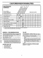
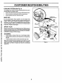
CUSTOMER
RESPONSIBILITIES
MAINTENANCE
SCHEDULE
another free manual from www.searstractormanuals.com
FILL IN DATES
AS YOU COMPLETE
REGULAR SERVICE
Check Engine Oil Level
SERVICE
If
DATES
If
Change Engine Oil
_1,2
Oil Pivot Points
V'
Inspect Spark Arrester/Muffler
Inspect Air Screen
If
I_
Clean or Replace Air Cleaner Cartridge
I_ 2
Clean Engine Cylinder Fins
I/
Replace Spark Plug
I/
1 - Change more often when operatingundera heavy load or in high ambienttemperatures.
2 - Service more oftenwhen operatingin dirtyor dusty conditions.
GENERAL
TILLER
RECOMMENDATIONS
The warranty on this attachment does not cover items that
have been subjected to operator abuse or negligence. To
receive full value from the warranty, operator must maintain
unit as instructed in this manual.
TRANSMISSION
All adjustments in the Service and Adjustments section of
this manual should be checked at least once each season.
Once a year you should replace the spark plug, clean or
replace air filter, and check tines and belts for wear. A
new spark plug and clean air filterassure proper air-fuel
mixture and help your engine run better and last longer.
BEFORE
•
•
•
•
Check
Check
Check
Check
EACH
(See Fig. 6)
Check transmission oil level after first five (5) hours of
operation and every ten (10) hours thereafter.
•
Check transmission oil with the tiller leveled on level
ground.
•
Remove oil fill plug. Oil should be level with the bottom
of filler plug hole. If necessary add SAE 30 motor oilor
equivalent. SAE 5W-30 motor oilmay be used in areas
where temperature is consistently 32°F or lower.
•
Tighten oilfill plug securely each time you check the oil
level.
Some adjustments will need to be made periodically to
properly maintain your unit.
•
LUBRICATION
NOTE: It is not necessary to change the oil in tiller
transmission. If for any reason, it must be changed,
capacity is 1-1/4 quarts.
USE
engine oil level.
brake operation.
tire pressure.
for loose fasteners.
7
CUSTOMER
RESPONSIBILITIES
TO CHANGE
ENGINE
OIL (See Figs. 6 and 7)
another free manual from www.searstractormanuals.com
Determine temperature range expected before oil change.
All oil must meet API service classification SF or SG.
•
•
•
Be sure tiller engine is level.
Oil will drain more freely when warm.
Catch oil in a suitable container.
•
•
•
Remove drain plug.
Tip tiller forward to drain oil.
After oil has drained completely, replace oil drain plug
and tighten securely.
Remove oil filler plug. Be careful not to allow dirt to enter
theengine.
Refill engine with oil. See "CHECK ENGINE OIL
LEVEL" in the Operation section of this manual.
•
•
AIR FILTER
8)
FOAM PRE-CLEANER
Your engine will not run properly and may be damaged by
using a dirty air filter. Remove cartridge every 25 hours and
tap to clean. Replace paper cartridge once a year or after
every 100 hours of operation, more often if used in very
dusty, dirty conditions.
•
Remove wing nut and cover.
•
Remove foam pre-cleaner element by sliding it off of the
paper cartddge.
•
Wash foam pre-cleaner in liquid detergent and water.
•
Wrap foam pre-cleaner in cloth and squeeze dry.
•
Lightly coat foam pre-cleaner with clean engine oil.
Squeeze in towel to remove excess oil. Do not saturate.
•
Install foam pre-cleaner over paper cartridge.
Reassemble cover and tighten wing nut securely.
FIG. 6
ENGINE
-_
WINGNUT
LUBRICATION
COVER
Use only high quality detergent oil rated with API service
classification SF or SG. Select the oil's SAE viscosity grade
according to your expected temperature.
PAPER
-20 °
-30 o
0=
-20 o
30_
-10 o
32 o 40_
0°
(See Fig.
60 °
10 _
.
80 _
20 °
FOAM
PRE-CLEANER
100 °
30 °
40 °
FIG. 7
NOTE: Although multi-viscosity oils (5W-30, 10W-30,
etc.) improve starting in cold weather, these multiviscosity oils will result in increased oil consumption
when used above 32°F (0°C). Check your engine oil level
more frequently to avoid possible engine damage from
running low on oil.
Change the oil after every 25 hours of use, or at least
once a year if the tiller is not used for 25 hours in one
year.
Check the crankcase oil level before starting the engine
and after each five (5) hours of continuous use. Add SAE
30 motor oil or equivalent. Tighten oil filler plug securely
each time you check the oil level.
PIG. 8
8
CUSTOMER
COOLING
SYSTEM
RESPONSIBILITIES
(See Fig. 9)
Yourengineisaircooled Forproperengineperformanceand
long life keep your engine clean
•
Clean air screen frequently using a stiff bristled brush
•
Remove blower housing and clean as necessary
•
Keep cylinder fins free of dirt and chaff
OPPOSITE
SIDE
SPARK PLUG
WIRE AND COVER
another free manual from www.searstractormanuals.com
MUFFLER
Do not operate tiller without muffler. Do not tamper with
exhaust system. Damaged mufflers or spark arresters could
create a fire hazard. Inspect periodically and replace if
necessary. If your engine is equipped with a spark arrester
screen assembly, remove every 50 hours for cleaning and
inspection. Replace if damaged.
SPARK
AIR
CLEANER
PLUG
CARBURETOR
.THROTTLE
CONTROL
"
Replace spark plugs atthe beginning of each tilling season
or after every 50 hours of use, whichever comes first. Spark
plug type and gap setting is shown in "PRODUCT SPECIFICATIONS" on page 3 of this manual.
CLEANING
•
•
Clean engine, wheels, finish, etc of all foreign matter
Keep finished surfaces and wheels free of all gasoline,
oil, etc.
•
Protect painted surfaces with automotive type wax
SCREEN
We do not recommend using a garden hose toclean your unit
unless the muffler, air filter and carburetor are covered to
keep water out Water in engine can result in a shortened
engine life
9
BLOWER
HOUSING
SERVICE AND ADJUSTMENTS
I_
CitAhUTIluOgN"
Disconnectsparkplugwiresfromsparkplugand
placewirewhereitcannotcomeintooontact
I
TILLER
TO ADJUST
GAUGE
See 'q'O ADJUSTTILLING
this manual.
another free manual from www.searstractormanuals.com
TO ADJUST
BELT
WHEELS
DEPTH" in Operation section of
TINE CLUTCH
LEVER
ENGINE
- SHEAVE
(SET
SCREW
END)
(See Fig. 10)
The clutch is a belt-tightener type. Belt should be just tight
enough to prevent slipping. Over-tightening will reduce belt
life.
•
•
•
To tighten belt, remove retainer spdng securing belt
tightener link to clutch lever and arm.
Standing in front of tiller, turn link in a counterclockwise
direction one turn at a time, until belt no longer slips.
After initial adjustment, a force of approximately 10 Ibs.
at the end of the lever should engage the clutch. This
would be heavy thumb pressure.
TO REPLACE
•
•
•
CAUTION:
BELT
GUARD
BELT (See Fig. 10)
Remove the three bolts holding belt guard to tiller.
Remove guard.
Remove old belt.
Install new belt so that lower side of belt is above idler
as shown.
TINE CLUTCH
LEVER
)
•
•
Adjust belt (see "TO ADJUST BELT" above).
Replacebeltguard. Makesureallmovingpartswillclear
belt guard.
NOTE: If it should become necessary to remove the
engine sheave, be sure that it is reinstalled so that the
set screw end is toward the outside.
ENGINE
"DISENGAGED"
k
POSITION 10 LB. \
(HEAVY THUMB
PRESSURE)
Maintenance, repair, or replacement of the emission control
devices and systems, which are being done at the customers expense, may be performed by any non-road engine
repair establishment or individual. Warranty repairs must be
performed by an authorized engine manufacturer's service
outlet.
TO ADJUST
REMOVED.
\
FIG. 1O
CARBURETOR
The carburetor has been preset at the factory and adjustment should notbe necessary. However, minor adjustments
may be required to compensate
for differences
in fuel,
temperature,
altitude or load. If the carburetor
does need
adjustment,
contact your nearest authorized
srvice center/
department.
IMPORTANT:
NEVER TAMPER
WITH THE ENGINE
GOVERNOR,
WHICH IS FACTORY SET FOR PROPER
ENGINE SPEED. OVER-SPEEDING
THE ENGINE ABOVE
THE
FACTORY
HIGH
SPEED
SETTING
CAN BE
DANGEROUS.
tF YOU THINK THE ENGINE-GOVERNED
HIGH SPEED NEEDS
ADJUSTING,
CONTACT
YOUR
NEAREST AUTHORIZED
SERVICE CENTER, WHICH HAS
PROPER EQUIPMENT AND EXPERIENCE
TO MAKE ANY
NECESSARY
ADJUSTMENTS.
10
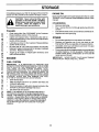
STORAGE
Immediately prepare your tiller for storage at the end of the
season or if the unit will not be used for 30 days or more.
A
ENGINE OIL
Drain oil (with engine warm) and replace with clean oil. (See
"ENGINE" in the Customer Responsibilities section of this
manual).
CAUTION: Never store the tiller with
gasoline in the tank inside a building
where fumes may reach an open flame
or spark. Allow the engine to cool
before storing in any enclosure.
CYLINDER(S)
•
•
another free manual from www.searstractormanuals.com
TILLER
•
•
Clean entire tiller (See "CLEANING" in the Customer
Responsibilities section of this manual).
Inspect and replace belts, if necessary (See belt replacement instructions in the Service and Adjustments
section of.this manual).
Lubricate as shown in the Customer Responsibilities
section of this manual.
OTHER
•
•
•
Be sure that all nuts, bolts and screws are securely
fastened. Inspect moving parts for damage, breakage
and wear. Replace if necessary.
Touch up all rusted or chipped paint surfaces; sand
lightly before painting.
•
FUEL SYSTEM
IMPORTANT:
IT IS IMPORTANT TO PREVENT GUM
DEPOSITS FROM FORMING IN ESSENTIAL FUEL SYSTEM
PARTS SUCH AS THE CARBURETOR, FUEL FILTER,
FUEL HOSE, OR TANK DURING STORAGE. ALSO,
EXPERIENCE INDICATES THAT ALCOHOL BLENDED
FUELS (CALLED GASOHOL OR USING ETHANOL OR
METHANOL) CAN ATTRACT MOISTURE WHICH LEADS
TO SEPARATION AND FORMATION OF ACIDS DURING
STORAGE. ACIDIC GAS CAN DAMAGE THE FUEL
SYSTEM OF AN ENGINE WHILE IN STORAGE.
•
Drain the fuel tank.
•
•
Do not store gasoline from one season to another.
Replace your gasoline can if your can starts to rust,
Rust and/or dirt in your gasoline will cause problems,
If possible, store your unit indoors and cover it to give
protection from dust and dirt.
Cover your unitwith a suitable protective cover that does
not retain moisture. Do not use plastic. Plastic cannot
breathe which allows condensation to form and will
cause your unit to rust.
IMPORTANT:
NEVER COVER TILLER WHILE ENGINE
AND EXHAUST AREAS ARE STILL WARM.
ENGINE
•
Remove spark plug,
Pour 1 ounce (29 ml) of oilthrough spark plug hole into
cylinder.
Pull starter handle slowly several times to distribute oil.
Replace with new spark plug.
Start the engine and let it run until the fuel lines and
carburetor are empty,
Never use engine or carburetor cleaner products in the
fuel tank or permanent damage may occur,
Use fresh fuel next season.
NOTE: Fuel stabilizer is an acceptable alternative in
minimizing the formation of fuel gum deposits during
storage. Add stabilizer to gasoline in fuel tank or storage
container. Always follow the mix ratio found on stabilizer
container. Run engine at least 10 minutes after adding
stabilizer to allow the stabilizer to reach the carburetor.
Do not drain the gas tank and carburetor if using fuel
stabilizer.
11
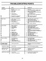
TROUBLESHOOTING
CAUSE
PROBLEM
another free manual from www.searstractormanuals.com
Will not start
Hard tostsrt
Loss of power
overheats
CORRECTION
1.
Out of fuel.
2.
3.
4.
5.
Engine not "CHOKED"
Engine flooded.
Dirty air cleaner.
Water in fuel.
6.
7.
Clogged fuel tank.
Loose spark plug wire.
6.
8.
9.
Bad spark plug or improper gap.
Carburetor out of adjustment.
8.
9.
1.
Throttle control not set properly.
2.
3.
4.
5.
Dirty air cleaner.
Bad spark plug or improper gap.
Stale or dirty fuel.
Loose spark plug wire.
1.
2.
3.
4.
5.
6.
Carburetor out of adjustment.
6.
1.
2.
3.
4.
5.
Engine is overloaded.
Dirty air cleaner.
Low oil level/dirty oil.
Faulty spark plug.
Oil in fuel.
1.
2.
3.
4.
5.
Set depth stake for shallower tilling.
Replace air cleaner cartridge.
Check oil level/change oil.
Clean and regap or change spark plug.
Drain and clean fuel tank and refill, and clean
carburetor.
6.
7.
Stale or dirty fuel.
Water in fuel.
6.
7.
Clogged fuel tank.
Spark plug wire loose.
Dirty engine air screen.
Dirty/clogged muffler.
Carburetor out of adjustment.
Poor compression.
8.
Drain fuel tank and refill with fresh gasoline.
Drain fuel tank and carburetor, and refill tank with
fresh line.
Remove fuel tank and clean.
8.
9.
10.
11.
12.
13.
Engine
POINTS
properly.
1.
Fill fuel tank.
2.
3.
4.
5.
See "TO START ENGINE" in Operation section.
Wait several minutes before attempting to start.
Replace air cleaner cartridge.
Drain fuel tank and carburetor, and refill tank with
fresh gasoline.
Remove fuel tank and clean.
7.
9.
10.
11.
12.
13.
Make sure spark plug wire is seated propedy on
plug.
Replace spark plug or adjust gap.
Make necessary adjustments.
Place throttle control in =FAST_ position.
Replace air cleaner cartridge.
Replace spark plug or adjust gap.
Drain fuel tank and refill with fresh gasoline.
Make sure spark plug wire is seated properly on
p_ug.
Make necessary adjustments.
Connect and tighten spark plug wire.
Clean engine air screen.
Clean/replace muffler.
Make necessary adjustments.
Contact an authorized Service Center.
1.
2.
3.
4.
5.
Low oil level/dirty oil
Dirty engine air screen.
Dirty engine.
ParUally plugged muffler.
Improper carburetor adjustment.
1.
Ground too dry and hard.
Soil balls up or clumps
1.
Ground too wet.
1.
Wait for more favorable
Engine runs but tiller
tines won't move
1.
2.
3.
"fine clutch Control is not engaged.
V-belt not correctly adjusted.
V-belt is off pulley(s).
1.
2.
3.
Engage tine clutch control.
Inspect/adjust V-belt.
Inspect V-belt.
Engine runs but
1.
2.
Tiningtoodeep.
Carburetor out of adjustment.
1.
2.
Set gauge wheels for shallower tilling.
Make necessary adjustments.
Excessive
difficult
bounce/
1.
2.
3.
4.
Check oil level/change oil.
Clean engine air screen.
Clean cylinder fins, air screen, and muffler area.
Remove and clean muffler.
5.
Adjust carburetor to dcher position.
Moisten ground or wait for more favorable
senditions.
handling
labors
12
soil conditions.
soil
another free manual from www.searstractormanuals.com
SERVICE NOTES
13
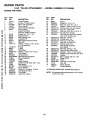
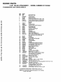
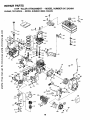
REPAIR PARTS
8 HP TILLER A'I-I'ACHMENT - - MODEL NUMBER 917,242484
ENGINE
AND TINES
D
another free manual from www.searstractormanuals.com
37-
5
26
4
27
24
28
27
43
45
46
+,69
36
_51
67
_)
50
42
46
51
49
19
38
39
14
40
@
_
47
41
30
REPAIR PARTS
8 HP TILLER ATTACHMENT
another free manual from www.searstractormanuals.com
ENGINE
PART
NO.
i
2
3
4
5
6
7
132776
6924J
67-7A860
132044
6"77A855
6922R
16
17
18
19
20
21
22
23
24
25
26
27
28
29
30
31
32
33
917.242484
AND TINES
KEY
NO,
9
10
11
12
13
14
15
- - MODEL NUMBER
DESCRIPTION
ControlThrottle
Bracket, Throttle Control
Hitch Yoke Assembly
Cover, Handle
Hitch Channel Assembly
Plate, Adapter
Engine Tecumseh
Model No. HM80-155644U
4914H
Square Key 1/4 x 1-1/4
8249R
Engine Sheave
6652H.
Belt Tightener Link
6656H
Adjusting Pin
624A12
Idler Support Plate and Pivot
2360J
Idler Arm
19151116
Washer 15/32 x 11/16 x 16 Ga.
(0 - 2 as required)
12000015
*E-Ring
6683H
E-Ring
4933H
Idler Pulley
STD551037
Washer 13/32 x 7/8 x 14 Ga.
4497H
Clip, Hairpin
626A430
Lever and Arm
634A726558 Belt Guard and Supports
163204
Decal, Craftsman
102655X
V-Belt
120075X
Decal,Caution
4929H
Ddlled Pan Hd. Rivet 3/8 x 1-3/4
3146R
Clip, Hairpin
626A401
Tine Weldment, L.H.
8212R
Decal, On/Off
71180512
Screw, FI. Hd. Mech. 5/16-24
626A402
Tine Weldment, R.H.
8224R558
Tine Shield
76020516
Cotter Pin 5/32 x 1
KEY
NO.
PART
NO,
34
35
36
37
38
39
40
41
42
8905R
76020824
74760516
19131311
STD551137
STD541037
74760524
STD541031
15760512
43
44
45
46
47
48
STD522510
STD551125
STD541025
74770512
STD551131
23200506
49
50
51
52
53
67
68
69
70
71
72
--
STD523715
STD541437
STD551031
11050500
19121214
STD533717
167258
STD511005
STD541462
4171R
108591X
179021
DESCRIPTION
Spring
Cotter Pin 1/4 x 1-1/2
*Bolt, Hex 5/16-18 x 1 Gr. 2
Washer 13/32 x 13/16 x 11 Ga.
*Washer Lock, Hvy. Hel. Spring
*Nut, Hex 3/8-16 UNC
*Bolt, Hex 5/16-18 x 1-1/2 Gr. 2
*Nut, Hex 5/16-18 UNC
Hex Bolt with Sems Ext. Washer
Lock 5/16-18 UNC x 3/4
*Hex Bolt 1/4-20 x 1
*Washer Lock 1/4
*Hex Nut 1/4-20 UNC
*Hex Bolt 5/16-24 x 3/4
*Washer Lock 5/16
Hex Socket Set Screw
5/16-18x3/8
*Hex Bolt 3/8-16 x 1-1/2
*Hex Lock Nut 3/8-16 UNC
*Washer 11/32 x 11/16 x 16 Ga.
Washer Lock External Tooth 5/16
Washer
Bolt, Carriage 3/8-16 x 1-3/4
Decal, 8 H.P.
Screw
Nut, Keps #10-24 UNC
Clip - Ins
Decal, Throttle
Owner's Manual
*STANDARD HARDWARE--PURCHASE
LOCALLY
NOTE: All component dimensions given in U.S. inches.
1 inch = 25.4 mm.
15
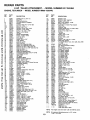
REPAIR PARTS
8 HP TILLER A'I'rACHMENT
another free manual from www.searstractormanuals.com
TRANSMISSION
AND
GAUGE
- - MODEL NUMBER
917.242484
WHEELS
33
34
4
36
12%
26
12
10
15
/
16
20
2O
14
19
18
A
B
D
E
F
39
(_44
40
_,3
17
G
43
¢_44
_35
16
/
16 15
13
7
REPAIR PARTS
8 HP TILLER A'rrACHMENT
another free manual from www.searstractormanuals.com
TRANSMISSION
AND GAUGE
- - MODEL NUMBER 917,242484
WHEELS
KEY
NO,
PART
NO.
1
2
3
4
5
634A562
9135R
4929H
634A61
634A559
6
7
9
10
12
13
14
15
16
17
18
169374
4898H
7356O600
5020J
4895H
92O4H
4932H
4910H
3039R
4877H1
634A553
19
2O
21
24
26
27
28
29
30
31
32
33
34
35
36
37
2601R
4870H
634A555
2600R
1370H
4912H
634A59
634A58
9858M1
634A57
5855H
6672H
4913H
1685H
13060400
634A554
38
39
4O
43
44
45
46
48
49
4878H1
STD551137
STD541037
7850H
STD551031
STD523722
17860524
STD523120
20000524
50
51
74780596
15760512
DESCRIPTION
Transmission
Retainer Spring
Drilled Pan Head Rivet 3/8 x 1-3/4
Gauge Wheel Sleeve and Brackets
Gauge Wheel Adjusting Shaft and
Bracket
Wheel
Shoulder Bolt
Locknut 3/8-16 UNC Nylock
Needle Bearing
Needle Beadng
Locknut 1/2-20 UNF
Input Sheave
Oil Seal
Needle Bearing
Gear Case Shield L.H.
Gear Case and Bearings L.H. Half
(Inc. Key No's. 10,12,16 & 20)
Gasket
Thrust Cap
Tine Shaft and Sprocket
RollerChain
Thrust Washer
Gasket
2nd Reduction Shaft and Gears
1st Reduction Shaft and Gears
Woodruff Key 3/16 x 5/8
Input Shaft and Pinion
Relief Valve
Gear Shift Cover
Gasket
Locknut 5/16-18 UNC
Pipe Plug 1/2-14 N.P.T.
Gear Case and Bearings R.H. Half
(Inc. Key No's. 12, 16 & 20)
Gear Case Shield R.H.
*Washer Lock 3/8
*Hex Nut 3/8-16 UNC
Spacer
*Washer 11/32 x 11/16 x 16 Ga.
*Hex Bolt 3/8-16 x 2-1/4
Hex Hal. RolI-Lok Thd. Forming Screw 5/16-18 x 1-1/2
*Hex Bolt 5/16-18 x 2
Flat Hd. Slotted RolI-Lok Thd.
Forming Screws 5/16-18 x 3/4
Hex Bolt 5/16-18 x 6 Gr. 5
Screw Mach. Hex Hd. 5/16-18 x 3/4
*STANDARD HARDWARE--PURCHASE
LOCALLY
NOTE: All component dimensions given in U.S. inches.
1 inch = 25.4 ram.
17
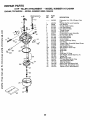
REPAIR PARTS
8 HP TILLER A'I-rACHMENT
another free manual from www.searstractormanuals.com
ENGINE, TECUMSEH
- - MODEL
NUMBER
- - MODEL NUMBER 917.242484
HM80-155644U
I
I
35
80
37
"292
83 81
308
75 7
/
87
70
69
50_
I
101
,d_ -325
169!
25
182
275
276
277
277A
18
20
26
,110
REPAIR PARTS
8 HP TILLER ATTACHMENT
another free manual from www.searstractormanuals.com
ENGINE, TECUMSEH
KEY
NO.
PART
NO.
1
2
4
4A
14
15
15A
15B
16
17
18
19
20
25
26
28
30
35
36
37
38
40
40
41
41
42
42
43
45
47
48
49
50
60
65
69
70
71
72
75
80
81
82
83
84
86
87
89
90
92
93
100
101
102
103
110
119
129
125
125
126
127
128
130
130A
130B
135
139
140
149
149A
150
151
169
170
171
172
35385
27652
30968
32214
28277
30699
30700
650494
37255A
29916
651028
34663
35319
36460
650561
30322 .
35372A
29826
29918
29216
29642
40011
40012
40009
40010
40013
40014
27888
36897
651033
34034
36896
35375
33273A
650128
37342
35376A
35377
27642
35319
37587
651080
37588
30588A
29193
650833
650832
32589
611090
650880
650881
35135A
610118
651024
651007
35187
36448
36449
27878A
27880A
34035
650691
650690
650694A
650727
650273
33636
33369
650836
27882
35862
27881
32581
27896A
28423
28424
28425
- - MODEL
NUMBER
- - MODEL NUMBER
917,242484
HM80-155644U
DESCRIPTION
Cylinder (Incl. 2, 20 & 72)
Dowel Pin
Oil Drain Extension
Oil Drain Elbow 45 Degrees
Washer
Covemor Rod (Incl. 15A & 15B)
Governor Yoke
Screw, 6-40 x 5/16"
Governor Lever (Incl. 212A)
Governor Lever Clamp
Screw, T-15, 8-32 x 7/16"
Speed Control Spring
Oil Seal
Blower Housing Baffle
Screw, 1/4-20 x 19/32"
Lock Nut, 8-32
Crankshaft
Screw, 10-32 x 3/4"
Lock Washer
Lock Nut, 10-32
Retaining Ring
Piston, Pin & Ring Set (Std.)
Piston, Pin & Ring Set (.010" OS)
Piston & Pin Ass'y. (Std.) (Incl. 43)
Piston & Pin Ass'y. (.910" OS) (Incl. 43)
Ring Sot (Std.)
Ring Set (.010" OS)
Piston Pin Retaining Ring
Connecting Rod Ass'y. (Incl. 47 & 49)
Connecting Rod Bolt
Valve Lifter
Oil Dipper
Camshaft (MCR)
Blower Housing Extension
Screw, 10-24 x 1/2"
* Cylinder Cover Gasket
Cylinder Cover (Incl. 71,75,80 Thru 84)
Crankshaft Bushing
Oil Drain Plug
Oil Seal
Governor Shaft
Washer
Governor Gear Ass'y. (Incl. 81)
Governor Spool
Retaining Ring
Screw, 1/4-20 x 1-3/16"
Screw, 1/4-20 x 1-11/16"
Flywheel Key
Flywheel
Lock Washer
Flywheel Nut
Solid State Ignition (Incl. 101)
Spark Plug Cover
Solid State Mounting Stud
Screw, T-15, 10-24 x 15/16"
Ground Wire
* Cylinder Head Gasket
Cylinder Head
Exhaust Valve (Std.) (Incl. 151)
Exhaust Valve (1/32" OS) (Incl. 151)
Intake Valve (Std.) (Incl. 151)
Washer
Belleville Washer
Screw, 5/16-18 x 2"
Screw, 5/16-18 x 1-25/32"
Screw, 5/16-18 x 17/32"
Resistor Spark Plug (RJ17LM)
Governor Gear Bracket
Screw, 10-24 x 1/2"
Valve Spring Cap
Valve Spring Cap
Valve Spring
Valve Spring Keeper
* Breather Gasket
Breather Body
Breather Element
Valve Cover
KEY
NO.
PART
NO.
173
173A
174
178
182
184
185
186
200
203
204
206
207
209
210
211
212A
223
224
227A
34696
32446
650128
29752
30088A
33263
34707
34667
34664
31342
651029
610973
37448
650821
27793
28942
36288
650378
27915A
35044
228
232
234
235
238
239
239A
241A
242
245
245A
250
251
260
261
262
264A
265
275
276
277
277A
278
280
281
282
285
287
290
292
298
300
301
304
305
307
308
310
325
327
340
341
342
370E
380
390
400
416
429
650851
650852
30675
650163
27272A
34698A
37279
34699
34700B
34703
34702
650886
34833B
650788
29747S
650802
33272D
34185B
31588
650729
651036
36908
36799A
33013
650760
35985B
29752
30705
26460
650665
34156A
36246
35480
35554
35499
35540
36205
29443
35392
36598
35834
30063
37089
640268
590746
36450C
34479A
730225A
756316S
19
DESCRIPTION
•
*
*
*
Breather Tube
Breather Tube Grommet
Screw, 10-24 x 1/2"
Nut & Lock Washer, 1/4-28
Screw, 1/4-28 x 1"
Carburetor To Intake Pipe Gasket
Intake Pipe
Governor Link
Control Bracket (Incl. 19, 203 & 204)
Compression
Spring
Screw, T-10, 5-40 x 7/16"
Terminal
Throttle Link
Screw, 10-32 x 1/2"
Conduit Clip
Screw, 10-32 x 3/8"
Bushing
Screw, T-30, 5/16-18 x 1-3/32"
Intake Pipe Gasket
Air Cleaner Elbow Ass'y. (Incl. 228, 232, 239A
1 & 242)
Stud, 1/4-20 x 8.1
Pop Rivet (Purchase Locally)
Nut, 1/4-20
Air Cleaner Elbow Fitting
Screw, 10-32 x 7/8"
Air Cleaner Gasket
Air Cleaner Gasket
Air Cleaner Collar
Air Cleaner Bracket
Air Cleaner Filter
Air Cleaner Filter
Air Cleaner Cover
Wing Nut, 1/4-20
Blower Housing
Screw, 5/16-18 x 3/4"
Screw, T-40, 5/16-24 x 21/32"
Screw, 1/4-20 x 5/8"
Cylinder Head Cover
Muffler
Locking Plate
Screw, 5/16-18 x 3-3/16"
Screw, 5/16-18 x 3-31/32"
Spacer
Heat Shield (Incl. 277A & 278)
Starter Bubble Cover
Screw, 8-32 x 3/8"
Starter Cup
Nut & Lock Washer, 1/4-28
Fuel Line
Fuel Line Clamp
Screw, 1/4-15 x 3/4"
Fuel Tank (Incl. 292 & 301)
Fuel Cap
Fuel Cap Retainer
Oil Fill Tube
"O" Ring
Fill Tube Clip
Dipstick
Wire Clip
Screen Plug
Fuel Tank Bracket
Fuel Tank Bracket
Screw, T-30, 1/4-20 x 1/2"
AirCleaner Decal
Carburetor (Incl. 184 & 212A)
Rewind Starter
Gasket Set (Incl. Items Marked *)
Spark Arrestor Kit (Optional)
SAE 30 4-Cycle Engine Oil (Quart)
Replacement Engine
Shortblock
PRM Low 1700
RPM High 3350 to 3650
NOTE:
This engine could have been built with 590704 starter.
NOTE:
All component dimensions
1 inch = 25.4 mm
given in U.S. inches
REPAIR PARTS
8 HP TILLER A'n'ACHMENT
ENGINE, TECUMSEH
- - MODEL
NUMBER
- - MODEL NUMBER
HM80-155644U
1A_
KEY
NO.
PART
NO.
640268
another free manual from www.searstractormanuals.com
917.242484
1
1A
2
4
5
6
7
10
11
12
13
14
15
16
17
18
20
20A
25
27
28
29
30
31
36
37
40
44
47
48
60
_37
.6_.37
25.
40t'4_LI
20
632798
36288
631970
631184
631183
640109
650506
632217
632O43
631184
631183
632799
630735
632164
651025
630766
640027
640053
631867
631024
632765
631028
631021
631022
640113
632547
640137
27110A
630748
631027
632760
DESCRIPTION
Carburetor (Incl. 184 of Engine Parts
List)
Throttle Shaft & Lever Assembly
Link Bushing
Throttle Return Spring
* Dust Seal Washer
* Dust Seal (Throttle)
Throttle Shutter
* Shutter Screw
Choke Shaft & Lever Assembly
Choke Return Spring
* Dust Seal Washer
* Dust Seal (Choke)
Choke Shutter
Choke Positioning Spring
Fuel Fitting
Throttle Crack Screw/Idle Speed Screw
Tension Spdng
Idle Restrictor Screw
Idle Restrictor Screw Cap
Float Bowl
* Float Shaft
Float
* Float Bowl "O" Ring
* Inlet Needle, Seat & Clip (Incl. 31)
Spring Clip
Main Nozzle Tube
* "O" Ring, Main Nozzle Tube
High Speed Bowl Nut
Bowl Nut Washer
* Welch Plug, Idle Mixture Well
* Welch Plug, Atmospheric Vent
Repair kit (Incl. Items Marked *)
REPAIR PARTS
8 HP TILLER A'I-FACHMENT - - MODEL NUMBER
ENGINE, TECUMSEH
- - MODEL
NUMBER
HM80-155644U
111
another free manual from www.searstractormanuals.com
13
917.242484
12
KEY
NO.
PART
NO.
DESCRIP_ON
1
2
3
4
5
6
7
8
11
12
13
590746
590599A
590600
590679
590601
590678
590680
590412
590681
590747
590535
59O7O1
Recoil Starter
Spring Pin (Incl. 4)
Washer
Retainer
Washer
Brake Spring
Starter Dog
Dog Spring
Pulley & Rewind Spring Assembly
Starter Housing Assembly
Starter Rope (Length 98" x 9/64" dia.)
Starter Handle
KEY
NO.
PART
NO.
DESCRIPTION
1
2
3
4
5
6
7
8
11
12
13
590704
590599A
590600
590696
590601
590697
590698
590699
590700
590705
590535
590701
Recoil Starter
Spdng Pin (Incl. 4)
Washer
Retainer
Washer
Brake Spnng
Starter Dog
Dog Spnng
Pulley & Rewind Spnng Ass'y
Starter Housing Ass'y.
Starter Rope ( 98" X 9/64" dia.)
Starter Handle
\8
61
_"6
_P_4
I
3
8_5
@_2
13
12
B--5
O--2
21
another free manual from www.searstractormanuals.com
SERVICE NOTES
22
another free manual from www.searstractormanuals.com
SERVICE NOTES
23
Get it fixed, at your home or ours!
another free manual from www.searstractormanuals.com
For repairof majorbrand appliances in your own home...
no matter who made it, no matter who sold it!
1-800-4-MY-HOME
_
Anytime,
dayornight
(1-800-469-4663)
(U.S.A. and Canada)
WWW.Sears.com
wlt_v.seal_.ca
For repair of carry-in products like vacuums, lawn equipment, and
electronics, call for the nearest Sears Parts and Repair Center.
1-800-488-1222
Any_me, dayor night (U.S.A. only)
w_Rv.seal_.com
For the replacement parts, accessories and owner's manuals
that you need to do-it-yourself, call Sears PartsDirectSM!
1-800-366-PART
(1-800-366-7278)
6 a.m.-
11 p.m., 7days aweek
(U.S.A. only)
www.sears,
conVparlsdirect
To purchase or inquire about a Sears Service Agreement
or Sears Maintenance Agreement:
1-800-827-6655
(u.s._)
7 a.m. - 5 p.m., CST, Mort. - Sat.
1-800-361-6665
(Canada)
9 a.m.- 8 p.m. EST, M- F, 4 p.m. Sat.
Parapedirservicio de repamci6na
Au Canada pour service en frarK;ais:
domicilio, y para ordenar piezas:
1-888..SU4-1OGAR s_
1-800-LE-FOYER Mc
(1_7)
www.sears.ca
(1-888-784,-6427)
© Seam,Roebuckand Co.
HomeO ntral®
J
® Registered Trademark / TM Trademark / SM Service Mark of Seam, Roebuck and Co.
® Marca Registrada / TMMarca de F_brica / SM Marca de Servicio de Seam, Roebuck and Co.
MCMarque de commerce / MDMarque deposee de Seam, Roebuck and Co.