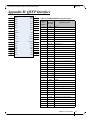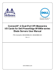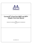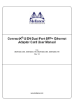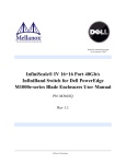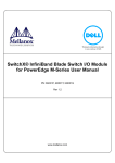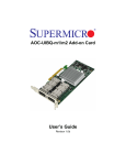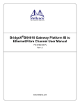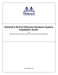
1
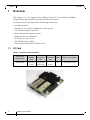
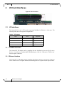
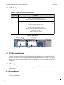
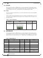
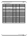
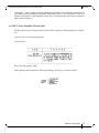
Dell and the Dell logo are
trademarks of Dell Inc.
ConnectX®-2 Dual Port I/O Card for Dell C6100
User Manual
MCQH29-XDR
Rev 1.0
www.mellanox.com
NOTE:
THIS HARDWARE, SOFTWARE OR TEST SUITE PRODUCT (“PRODUCT(S)”) AND ITS RELATED DOCUMENTATION ARE PROVIDED BY MELLANOX TECHNOLOGIES “AS-IS” WITH ALL FAULTS OF ANY KIND AND SOLELY FOR THE PURPOSE OF
AIDING THE CUSTOMER IN TESTING APPLICATIONS THAT USE THE PRODUCTS IN DESIGNATED SOLUTIONS. THE CUSTOMER'S MANUFACTURING TEST ENVIRONMENT HAS NOT MET THE STANDARDS SET BY MELLANOX TECHNOLOGIES
TO FULLY QUALIFY THE PRODUCTO(S) AND/OR THE SYSTEM USING IT. THEREFORE, MELLANOX TECHNOLOGIES CANNOT AND DOES NOT GUARANTEE OR WARRANT THAT THE PRODUCTS WILL OPERATE WITH THE HIGHEST QUALITY.
ANY EXPRESS OR IMPLIED WARRANTIES, INCLUDING, BUT NOT LIMITED TO, THE IMPLIED WARRANTIES OF MERCHANTABILITY, FITNESS FOR A PARTICULAR PURPOSE AND NONINFRINGEMENT ARE DISCLAIMED. IN NO EVENT
SHALL MELLANOX BE LIABLE TO CUSTOMER OR ANY THIRD PARTIES FOR ANY DIRECT, INDIRECT, SPECIAL, EXEMPLARY, OR CONSEQUENTIAL DAMAGES OF ANY KIND (INCLUDING, BUT NOT LIMITED TO, PAYMENT FOR PROCUREMENT OF SUBSTITUTE GOODS OR SERVICES; LOSS OF USE, DATA, OR PROFITS; OR BUSINESS INTERRUPTION)
HOWEVER CAUSED AND ON ANY THEORY OF LIABILITY, WHETHER IN CONTRACT, STRICT LIABILITY, OR TORT
(INCLUDING NEGLIGENCE OR OTHERWISE) ARISING IN ANY WAY FROM THE USE OF THE PRODUCT(S) AND RELATED
DOCUMENTATION EVEN IF ADVISED OF THE POSSIBILITY OF SUCH DAMAGE.
Mellanox Technologies
350 Oakmead Parkway Suite 100
Sunnyvale, CA 94085
U.S.A.
www.mellanox.com
Tel: (408) 970-3400
Fax: (408) 970-3403
Mellanox Technologies, Ltd.
PO Box 586 Hermon Building
Yokneam 20692
Israel
Tel: +972-4-909-7200
Fax: +972-4-959-3245
© Copyright 2010. Mellanox Technologies, Inc. All Rights Reserved.
Mellanox®, ConnectX®, BridgeX®, InfiniBlast®, InfiniBridge®, InfiniHost®, InfiniRISC®, InfiniScale®, and InfiniPCI® are
registered trademarks of Mellanox Technologies, Ltd.
PhyX and Virtual Protocol Interconnect are trademarks of Mellanox Technologies, Ltd.
All other marks and names mentioned herein may be trademarks of their respective companies.
ConnectX®-2 Dual Port VPI I/O Card for Dell C6100
2
Mellanox Technologies
Document Number: 3198
ConnectX®-2 Dual Port VPI I/O Card for Dell C6100
Rev 1.0
Table of Contents
Chapter 1
Chapter 2
Overview
8
1.1
1.2
8
9
I/O Card Interfaces
10
2.1
10
10
10
11
11
11
11
12
12
12
2.2
2.3
2.4
2.5
Chapter 3
Chapter 5
I/O Interfaces
2.1.1 InfiniBand Interface
2.1.2 Ethernet Interface
LED Assignment
PCI Express Interface
Memory
2.4.1 System Memory
2.4.2 EEPROM
2.4.3 Flash
EEPROM VPD
Driver Software and Firmware
14
3.1
14
14
14
14
14
3.2
3.3
Chapter 4
I/O Card
Finding the GUID/MAC and Serial Number on the Adapter Cards
Driver Software
3.1.1 Linux
3.1.2 Windows
Updating Card Firmware
FlexBoot
I/O Card Installation
15
4.1
4.2
4.3
4.4
15
15
16
19
Hardware and Software Requirements
Installation Kit
Installation Instructions
Safety Warnings
Cables and Modules
21
5.1
21
21
22
Appendix A
Appendix B
Appendix C
Appendix D
Cable Installation
5.1.1 Inserting a Cable into the Card
5.1.2 Removing a Cable from the Card
Specifications
QSFP Interface
Avertissements de sécurité d’installation (French)
Installation - Sicherheitshinweise (German)
23
27
29
30
Mellanox Technologies
3
Rev 1.0
List of Figures
Figure 1:
Card Product Labels
9
Figure 2:
PCI Connection
10
Figure 3:
Front Panel
11
Figure 4:
Flash Jumper
12
Figure 5:
Installation Kit Parts
16
Figure 6:
Removing From the Server
17
Figure 7:
Top View
17
Figure 8:
Install the Plastic Leg onto the Board
18
Figure 9:
Installing the Connector Board into the HCA Card
18
Figure 10: Dell Card Installed
18
Figure 11: Front Panel
19
Figure 12: Top View
19
Figure 13: Connector Orientation
22
Figure 14: Mechanical Drawing
23
Figure 15: QSFP Connector Male and Female Views
28
4
Mellanox Technologies
ConnectX®-2 Dual Port VPI I/O Card for Dell C6100
Rev 1.0
List of Tables
Table 1:
Revision History Table
6
Table 2:
Documents List
7
Table 3:
ConnectX-2 I/O Card Details
8
Table 4:
VPI Support
10
Table 5:
Jumper Configuration
12
Table 6:
MCQH29-XDR VPD
12
Table 7:
Hardware and Software Requirements
15
Table 8:
ConnectX® Dual-Port InfiniBand I/O Card Installation Kit
16
Table 9:
ConnectX-2 MCQH29-XDR Specifications
26
Mellanox Technologies
5
Rev 1.0
Revision History
This document was first printed on 5/6/10.
Table 1 - Revision History Table
6
Date
Rev
April 2010
1.0
Mellanox Technologies
Comments/Changes
Initial release
ConnectX®-2 Dual Port VPI I/O Card for Dell C6100
Rev 1.0
About this Manual
This User Manual describes ConnectX-2 Dual Port VPI I/O cards for the Dell C6100 chassis.
It provides details as to the interfaces of the board, specifications, required software and firmware
for operating the cards, installation instructions, and relevant documentation.
Intended Audience
This manual is intended for the installer and user of the I/O cards.
The manual assumes basic familiarity with the Infiniband® architecture specifications.
Related Documentation
Table 2 - Documents List
InfiniBand® Architecture Specification Volume 1 Release 1.2 and Volume 2 release
1.2.1– Infiniband Architecture Specifications Descriptions
PCI Express Base 2.0 Specification (1.1 compatible)
PCI Local Bus Specification Rev 2.3
Online Resources
• Mellanox Technologies Web pages: http://www.mellanox.com
• Dell Support Web pages: http://support.dell.com
Document Conventions
These symbols indicate a situation, status, or condition that may cause harm
to people or damage to the equipment.
When discussing memory sizes, MB and MBytes are used in this document to mean size in mega
bytes. The use of Mb or Mbits (small b) indicates size in mega bits.
Mellanox Technologies
7
Rev 1.0
1
Overview
Overview
This document is a User Manual for the Mellanox ConnectX-2 20 and 40Gb/s InfiniBand /
10GigE Ethernet dual port QSFP I/O cards for the Dell C6100 chassis.
The cards described in this manual have the following main features:
• 1μs MPI ping latency
• Selectable 10, 20, or 40Gb/s InfiniBand or 10GigE per port
• CPU offload of transport operations
• End-to-end QoS and congestion control
• Hardware-based I/O virtualization
• PCI Express 2.0 (up to 5GT/s)
• TCP/UDP/IP stateless offload
• Fibre Channel encapsulation (FCoIB or FCoE)
1.1
I/O Card
Table 3 - ConnectX-2 I/O Card Details
Ordering Part
Number (OPN)
MCQH29-XDR
8
PCI Express
SERDES
Speed
IB Data
Transmission
Rate
Eth Data
Transmission
Rate
PCIe Gen2
5.0 GT/s
InfiniBand
40 Gb/s QDR
10 Gb/s
Mellanox Technologies
RoHS
Adapter IC Part Number
R-6
MT25408B0-FCCR-QI
ConnectX®-2 Dual Port VPI I/O Card for Dell C6100
1.2
Rev 1.0
Finding the GUID/MAC and Serial Number on the Adapter Cards
All cards have a label on the printed side of the card that has the card serial number, the card MAC
for Ethernet protocol, and the card GUID for InfiniBand protocol. VPI Cards have both a MAC
and a GUID.
Figure 1: Card Product Labels
IL-0JR3P1-74031-980-0001
REV:A00
Made in IL
Model No: MCQH29-XDR
P/N: 0JR3P1
REV: X1
MAC: 0002C9011226 FC
GUID: 0024E89097FF24DC
Made in IL
Mellanox Technologies
9
Rev 1.0
2
I/O Card Interfaces
I/O Card Interfaces
Figure 2: PCI Connection
2.1
I/O Interfaces
The ConnectX-2 I/O card is VPI-capable, supporting InfiniBand or Ethernet on either port. The
following table shows the supported configurations.
Table 4 - VPI Support
Port 1
Port 2
Supported
IB
IB
supported
IB
EN
supported
EN
IB
not supported
EN
EN
supported
2.1.1 InfiniBand Interface
The ConnectX-2 VPI adapter card is compliant with the InfiniBand Architecture Specification,
Release 1.2.1. It has two compliant QSFP InfiniBand ports, with four Tx/Rx pairs of SerDes connected to QSFP connectors.
2.1.2 Ethernet Interface
The ConnectX® -2 VPI adapter card is compliant with the IEEE Std 802.3ae Specification. Each port
can be connected to a 10 Gigabit Ethernet switch through the use of QSFP to SFP+ hybrid cables.
10
Mellanox Technologies
ConnectX®-2 Dual Port VPI I/O Card for Dell C6100
2.2
Rev 1.0
LED Assignment
Table 5 - Physical and Logical Link Indications
Port Number
LED Name
Port 1
Physical Link - Green
Constant on indicates a good physical link
Blinking indicates a problem with the Physical link
Data Activity - Yellow
Blinking indicates Data Transfer
Constant on indicates no Data Transfer
Port 2
Physical Link - Green
Constant on indicates a good physical link
Blinking indicates a problem with the Physical link
Data Activity - Yellow
Blinking indicates Data Transfer
Constant on indicates no Data Transfer
Figure 3: Front Panel
Physical Connection
Port 1
2.3
Data Transfer
Port 2
PCI Express Interface
The I/O card attaches to the blade's PCI Express interface through a press fit connector. The PCI
Express x8 interface is version 2.0 compliant and compatible with base 1.1 chipsets. The device
can be either a master initiating the PCI Express bus operations or a slave responding to PCI bus
operations.
2.4
Memory
The I/O card supports multiple memory devices through the PCI Express, Flash, and I2C compatible interfaces.
2.4.1 System Memory
The I/O card utilizes the PCI Express interface to store and access fabric connection information
on the system memory.
Mellanox Technologies
11
Rev 1.0
I/O Card Interfaces
2.4.2 EEPROM
The I/O card incorporates an EEPROM that is accessible through the I2C-compatible interface.
The EEPROM is used for storing the Vital Product Data (VPD). The VPD format adheres to the
PCI Local Bus Specification Rev 2.3 VPD definition. The EEPROM capacity is 4Kb.
2.4.3 Flash
The I/O card includes one SPI Flash device accessible via the Flash interface of the MT25408B0
ConnectX-2 device.
There is a jumper on the card that indicates to the device whether an on-board Flash device is to be
used. Table 6 provides information on this jumper. See the schematic in Figure 14 on page 23 for
the jumper location.
Table 6 - Jumper Configuration
Description
Card Default
Configuration
Option
Flash present/
not present
connection open – Flash present
connection shorted – Flash not present
Comments
connection open –
Flash present
Header 1x2
Figure 4: Flash Jumper
2.5
EEPROM VPD
The I/O card incorporates an EEPROM that is accessible through the I2C-compatible interface.
The EEPROM is used for storing the Vital Product Data (VPD) and FRU. The VPD format
adheres to the PCI Local Bus specification rev 2.3 VPD definition. The EEPROM capacity is 4Kb.
Table 7 - MCQH29-XDR VPD
Offset (Decimal)
Item
Value
0
Large Resource Type ID String Tag (0x02)
0x82
1
Length
0x12
3
Data
"DELL PE C6100
MEZZ IB QDR"
21
Large Resource Type VPD-R Tag (0x10)
0x90
22
Length
0x43
24
VPD Keyword
“PN”
26
Length
0x6
27
Data
“059MP7”
33
VPD Keyword
“EC”
35
Length
0x3
12
Mellanox Technologies
Format
Description
Alphanumeric
Short description / ID
Read Only Area
Numbers
Add in Card Part Number
Alphanumeric
Engineering Change Level of the
card (rev)
ConnectX®-2 Dual Port VPI I/O Card for Dell C6100
Rev 1.0
Table 7 - MCQH29-XDR VPD
Offset (Decimal)
Item
Value
Format
Description
36
Data
”A00”
39
VPD Keyword
“SN”
41
Length
0x14
Alphanumeric
Serial Number
42
Data
“OO059MP7MM
MMMYMDSSSS
”
according to the board label
62
VPD Keyword
“V0”
Misc Information
64
Length
0x16
65
Data
"DELL PE C6100
MEZZ IB QDR"
87
VPD Keyword
“RV”
89
Length
0x1
90
Data
Checksum
91
Large Resource Type VPD-W Tag (0x11)
0x91
92
Length
0xA1
94
VPD Keyword
“V1”
96
Length
0x6
Read / Write Area
Driver version
97
Data
“N/A”
103
VPD Keyword
“YA”
Number
105
Length
0x20
106
Data
“N/A”
138
VPD Keyword
“RW”
140
Length
0x72
141
Data
Reserved (0x00)
255
Small Resource Type END Tag (0x11)
0x78
256
Mellanox Read Only Mask
0x0....0
Numbers
350
Mellanox Read/Write Mask
0x1...1
Numbers
511
Mellanox Read Only Mask
0x0
Numbers
Asset Tag
Alphanumeric
Remaining read/write area
Mellanox Technologies
13
Rev 1.0
Driver Software and Firmware
3
Driver Software and Firmware
3.1
Driver Software
3.1.1 Linux
For Linux, download and install the latest OpenFabrics Enterprise Distribution (OFED) software
package available via the Mellanox Web site at:
http://www.mellanox.com => Downloads => InfiniBand/VPI SW/Drivers. Follow the installation
instructions included in the download package.
3.1.2 Windows
For Windows, download and install the latest WinOF for VPI software package available via the
Mellanox Web site at:
http://www.mellanox.com => Downloads => InfiniBand/VPI SW/Drivers
3.2
Updating Card Firmware
Each card is shipped with the latest version of qualified firmware at the time of manufacturing.
Firmware is updated occasionally, and the most recent firmware can be obtained from
http://www.mellanox.com => Downloads => Firmware.
Firmware can be updated on the stand alone single card using the flint tool of the Mellanox Firmware Tools (MFT) package. This package is available for download, along with its user manual,
from the Mellanox Firmware Tools page. See http://www.mellanox.com => Downloads => Firmware Tools.
A firmware binaries table lists a binary file per card. The file name of each such binary is composed by combining the firmware name, the firmware release version, and the card part number.
Please contact Mellanox or your assigned Field Application Engineer if you cannot find the firmware binary for your adapter card.
3.3
FlexBoot
FlexBoot enables remote boot over Ethernet or InfiniBand using Boot over InfiniBand (BoIB),
Boot over Ethernet (BoE), or Boot over iSCSI (Bo-iSCSI). This technology is based on the Preboot Execution Environment (PXE) standard specification, and FlexBoot software is based on the
open source EtherBoot/gPXE project (see www.etherboot.org). For more information go to
http://www.mellanox.com > Products > InfiniBand/VPI SW/Drivers > FlexBoot.
14
Mellanox Technologies
ConnectX®-2 Dual Port VPI I/O Card for Dell C6100
4
I/O Card Installation
4.1
Hardware and Software Requirements
Rev 1.0
Before installing the VPI I/O card, please make sure that the system meets the hardware and software requirements listed in Table 8, “Hardware and Software Requirements”.
Table 8 - Hardware and Software Requirements
Requirement
Hardware
Software Operating
Systems/Distributions
Software Stacks
4.2
Description
Used with Dell C6100 chassis
Refer to the C6100 chassis Manuals
Mellanox OpenFabric software package (either MLNX_OFED for Linux or
MLNX_WinOF for Microsoft Windows)
Installation Kit
Make sure all of the parts are in the kit before you start the installation. If any parts are damaged or
missing, call your supplier immediately.
Mellanox Technologies
15
Rev 1.0
I/O Card Installation
The kit includes:
Table 9 - ConnectX® Dual-Port InfiniBand I/O Card Installation Kit
1 I/O Card
1 connector board
3 flathead screws
1 plastic leg
3 panhead screws
Figure 5: Installation Kit Parts
x3
x3
4.3
Installation Instructions
Remove the server from the chassis.
1. Connect an ESD strap to your wrist and to a valid ESD ground.
2. Push the latch and pull on the handle.
16
Mellanox Technologies
ConnectX®-2 Dual Port VPI I/O Card for Dell C6100
Rev 1.0
Figure 6: Removing From the Server
Screws holding the faceplate
Push here
Pull handle
3.
4.
5.
6.
Remove the server and place on a work bench.
Above the handle are screws holding on the faceplate.
Remove these screws and discard.
Remove the two screws on the top side of the server and discard.
Figure 7: Top View
Screws in top
7. Remove the faceplate.
8. Push the plastic leg onto the board.
Mellanox Technologies
17
Rev 1.0
I/O Card Installation
Figure 8: Install the Plastic Leg onto the Board
9. Push the Connector board into the card. The connector board must be installed as seen in
Figure 9, directed toward the back of the server.
Figure 9: Installing the Connector Board into the HCA Card
10. Put the card into place in the server, catching the cages into the front panel of the server. The
metal leg must go inside of the server and line up with the hole in the side of the server. Also
push the connector board into the socket in the server.
11. Screw in a flat head screw for the metal leg.
Figure 10: Dell Card Installed
Install a flathead screw
through the server into the
metal leg.
18
Mellanox Technologies
ConnectX®-2 Dual Port VPI I/O Card for Dell C6100
Rev 1.0
12. Screw in three panhead screws into the front panel.
Figure 11: Front Panel
Screws holding the faceplate
13. Screw in two flathead screws on the top of the server into the HCA card.
Figure 12: Top View
Screws in top
14. Slide the server in the chassis.
4.4
Safety Warnings
1. Installation Instructions
Read all installation instructions before connecting the equipment to the power
source.
Mellanox Technologies
19
Rev 1.0
I/O Card Installation
2. Over Temperature
This equipment should not be operated in an area with an ambient temperature
exceeding the maximum recommended: 55°C (131°F).
To guarantee proper air flow, allow at least 8cm (3 inches) of clearance around
the ventilation openings.
3. Lightening – Electrical Hazard
During periods of lightning activity, do not work on the equipment.
4. Installation of Equipment
This equipment should be installed, replaced, or serviced only by trained and
qualified personnel.
5. Disposal of Equipment
Disposal of this equipment should be in accordance to all national laws and
regulations.
6. Compliance with Local and National Codes
This equipment should be installed in compliance with local and national electrical codes.
20
Mellanox Technologies
ConnectX®-2 Dual Port VPI I/O Card for Dell C6100
5
Rev 1.0
Cables and Modules
These cards support passive copper cables and active optical cables, both direct attach and through
a transceiver module, at up to QDR data rates. See www.mellanox.com => Products => Cables for
cable type, model, module, and length recommendations.
5.1
Cable Installation
All cables can be inserted or removed with the unit powered on. To insert a cable, press the connector into the port receptacle until the connector is firmly seated. The GREEN LED indicator will
light when the physical connection is established (that is, when the unit is powered on and a cable
is plugged into the port with the other end of the connector plugged into a functioning port). After
plugging in a cable, lock the connector using the latching mechanism particular to the cable vendor. When a logical connection is made the YELLOW LED will come on. When data is being
transferred the yellow led will blink.
Note: When installing cables make sure that the latches engage.
Note: Always install and remove cables by pushing or pulling the cable and connector in a
straight line with the card.
Care should be taken not to impede the air exhaust flow through the ventilation holes. Cable
lengths should be used which allow for routing horizontally around to the side of the chassis before
bending upward or downward in the rack.
To remove a cable, disengage the locks and slowly pull the connector away from the port receptacle. Both LED indicators will turn off when the cable is unseated.
Cables, especially long copper cables, can weigh a substantial amount. Make
sure that the weight of the cable is supported on its own and is not hanging
from the adapter card.
5.1.1 Inserting a Cable into the Card
1. Support the weight of the cable before connecting the cable to the card. Do this by using a
cable holder or tying the cable to the rack.
2. Determine the correct orientation of the connector to the card before inserting the connector.
Do not try and insert the connector up side down. This may damage the card.
3. Insert the connector into the card. Be careful to insert the connector straight into the cage. Do
not apply any torque, up or down, to the connector cage in the card.
4. Make sure that the connector locks in place.
Mellanox Technologies
21
Rev 1.0
Cables and Modules
Figure 13: Connector Orientation
180o
5.1.2 Removing a Cable from the Card
1. Pull on the latch release mechanism thereby unlatching the connector and pull the connector
out of the cage.
2. Do not apply torque to the connector when removing it from the card.
3. Remove any cable supports that were used to support the cable’s weight.
22
Mellanox Technologies
ConnectX®-2 Dual Port VPI I/O Card for Dell C6100
Rev 1.0
Appendix A: Specifications
A.1 Board Mechanical Drawing and Dimensions
The ConnectX-2 I/O card mechanical drawing is depicted in Figure 14.
Figure 14: Mechanical Drawing
111.90
I2C interface J2
Flash Jumper J1
34.40
U3
H2
J2
H3
J1
16.60
59.70
79.30
J6 J4
J3
63.90
U1
10.80
L14
Q2
U6
U7
57.15
J5
Q1
U10
U9
U8
U5
U13
H1
10.03
4.60
2.60
Note: All dimensions are in millimeters.
J1 is the flash jumper.
J2 is the I2C Connector.
Mellanox Technologies
23
Rev 1.0
A.2 EMC Certification Statements
A.2.1 FCC Statements (USA)
Class A Statements:
§ 15.21
Statement
Warning! Changes or modifications to this equipment not expressly approved by the party
responsible for compliance (Mellanox Technologies) could void the user's authority to operate
the equipment.
§15.105(a)
Statement
NOTE: This equipment has been tested and found to comply with the limits for a Class A digital
device, pursuant to Part 15 of the FCC Rules. These limits are designed to provide reasonable
protection against harmful interference when the equipment is operated in a commercial environment. This equipment generates, uses, and can radiate radio frequency energy and, if not
installed and used in accordance with the instruction manual, may cause harmful interference
to radio communications. Operation of this equipment in a residential area is likely to cause
harmful interference in which case the user will be required to correct the interference at his
own expense.
A.2.2 EN Statements (Europe)
EN55022 Class A Statement:
Warning
This is a class A product. In a domestic environment this product
may cause radio interference in which case the user may be
A.2.3 ICES Statements (Canada)
Class A Statement:
“This Class A digital apparatus complies with Canadian ICES-003.
Cet appareil numérique de la classe A est conforme à la norme NMB-003 du Canada.”
A.2.4 VCCI Statements (Japan)
Class A Statement:
24
Mellanox Technologies
ConnectX®-2 Dual Port VPI I/O Card for Dell C6100
Rev 1.0
(Translation - "This is a Class A product based on the standard of the Voluntary Control Council
for Interference by Information Technology Equipment (VCCI). If this equipment is used in a
domestic environment, radio interference may occur, in which case the user may be required to
take corrective actions.")
A.2.5 KCC Notice (Republic of Korea Only)
The KCC label may be located separately from the other regulatory markings applied to your product.
Class A devices are for business purposes.
Class A Device
KCC Class A Regulatory Label
If the regulatory label includes the following marking, your device is a Class A product:
Mellanox Technologies
25
Rev 1.0
A.3 Specifications
Table 10 - ConnectX-2 MCQH29-XDR Specifications
Physical
Power and Environmental
Size:
Air Flow:
QSFP 40Gb/s
Connector:
79.30mm X 111.90 mm
200LFM @55°C
InfiniBand (Copper and optical)
Max power per port 3.5 W.
Voltage:
Typ Power:
Maximum Power:
Temperature:
Protocol Support
InfiniBand:
Ethernet:
QoS:
RDMA Support:
26
8.74W Passive cables
12.74W Active cables
10.11W Passive cables
14.11 Active cables
0°C to 55°C
Regulatory
IBTA v1.2.1, Auto-Negotiation
(20Gb/s@5Gt/s) or
(10Gb/[email protected]/s)
IEEE Std 802.3ae 10 Gigabit
Ethernet
IEEE Std 802.3ad Link Aggregation and Failover
IEEE Std 802.3x Pause
IEEE Std 802.1Q VLAN tags
IEEE Std 802.1p Priorities
Multicast
Jumbo frame support (10KB)
128 MAC/VLAN addresses per
port
8 Virtual Lanes for InfiniBand
8 Priority Queues for Ethernet
Yes, All Ports
Data Rate
SFP+ Ethernet:
10 Gb/s
QSFP InfiniBand:
40 Gb/s
PCI Express:
12V, 3.3V
2.0 SERDES @ 5.0 GT/s
Mellanox Technologies
Safety:
EMC (Emissions):
RoHS:
US/Canada: cTUVus
EU: IEC60950
International: CB
USA: FCC, Class A
Canada: ICES, Class A
EU: CE Mark (EN55022 Class A,
EN50024, EN61000-3-2, EN61000-33)
Japan: VCCI, Class A
Korea: KCC Class A
Australia/ New Zealand: C-Tick
Class A
R-6
ConnectX®-2 Dual Port VPI I/O Card for Dell C6100
Rev 1.0
Appendix B: QSFP Interface
20
21
22
23
24
25
26
27
28
29
30
31
GND
Rx2n
Rx1n
18
Rx2p
Rx1p
17
GND
GND
16
Rx4n
Rx3n
Rx4p
Rx3p
GND
GND
ModPrsL
SDA
IntL
SCL
VccTx
Vcc Rx
Vcc1
ResetL
LPMode
ModSelL
32
GND
GND
33
Tx3p
Tx4p
34
Tx3n
35
GND
Tx4n
GND
36
37
38
19
GND
15
Connector
Connector
Pin
Pin Name
Number
Signal Description
14
1
GND
Ground
13
2
Tx2n
Transmitter Inverted Data Input
12
3
Tx2p
Transmitter Non-Inverted Data Input
11
4
GND
Ground
10
5
Tx4n
Transmitter Inverted Data Input
9
6
Tx4p
Transmitter Non-Inverted Data Input
GND
Ground
8
7
6
5
4
Tx1p
Tx2p
3
Tx1n
GND
Tx2n
2
1
GND
Table 3- InfiniBand QSFP Connector Pinout
7
8
ModSelL Module Select
9
ResetL
Module Reset
10
Vcc Rx
+3.3 V Power supply receiver
11
SCL
2-wire serial interface clock
12
SDA
2-wire serial interface data
13
GND
Ground
14
Rx3p
Receiver Non-Inverted Data Output
15
Rx3n
Receiver Inverted Data Output
16
GND
Ground
17
Rx1p
Receiver Non-Inverted Data Output
18
Rx1n
Receiver Inverted Data Output
19
GND
Ground
20
GND
Ground
21
Rx2n
Receiver Inverted Data Output 3
22
Rx2p
Receiver Non-Inverted Data Output 3
23
GND
Ground
24
Rx4n
Receiver Inverted Data Output 3
25
Rx4p
Receiver Non-Inverted Data Output 3
26
GND
Ground
27
ModPrsL Module Present
28
IntL
Interrupt
29
Vcc Tx
+3.3 V Power supply transmitter
30
Vcc 1
+3.3 V Power Supply
31
LPMode
32
GND
Ground
33
Tx3p
Transmitter Non-Inverted Data Input
34
Tx3n
Transmitter Inverted Data Input
35
GND
Ground
36
Tx1p
Transmitter Non-Inverted Data Input
Low Power Mode
37
Tx1n
Transmitter Inverted Data Input
38
GND
Ground
Mellanox Technologies
27
7
8
9
10
11
12
13
14
15
16
17
18
19
ModSelL
ResetL
VccRx
SCL
SDA
GND
RX3p
RX3n
GND
RX1p
RX1n
GND
20 GND
21 RX2n
22 RX2p
23 GND
24 RX4n
25 RX4p
26 GND
27 ModPrsL
28 IntL
29 VccTx
30 Vcc1
31 LPMode
14
13
12
11
1
0
9
8
7
6
5
4
3
2
1
GND
32 GND
TX2n
6
GND
15
TX2p
33 TX3p
GND
5
TX4p
16
TX4n
34 TX3n
TX4p
4
TX4n
GND
19
18
17
ModSelL
35 GND
ResetL
3
GND
SCL
36 TX1p
SDA
2
TX2p
GND
37 TX1n
RX3p
1
TX2n
GND 3 8
TX1n 3 7
TX1p 3 6
GND 3 5
TX3n 3 4
TX3p 3 3
GND 3 2
LPMode 3 1
Vcc1 30
RX3n
VccRx
GND
RX1n
RX1p
GND
38 GND
Top
18.35
Top
18.35
View into Rear of
Connector
VccTx 29
IntL 28
ModPrsL 27
GND 26
RX4p 25
RX4n 24
GND 23
RX2p 22
RX2n 21
GND 20
Mellanox Technologies
28
GND
Rev 1.0
Figure 15: QSFP Connector Male and Female Views
8.50
View into Front of Cage
8.50
ConnectX®-2 Dual Port VPI I/O Card for Dell C6100
Rev 1.0
Appendix C: Avertissements de sécurité d’installation (French)
1. Instructions d’installation
Lisez toutes les instructions d’installation avant de brancher le matériel à la
source d’alimentation électrique.
2. Température excessive
Ce matériel ne doit pas fonctionner dans une zone avec une température ambiante dépassant le maximum recommandé de 55°C (131°F). Un flux d’air de
200LFM à cette température ambiante maximale est nécessaire. En outre, pour
garantir un bon écoulement de l’air, laissez au moins 8 cm (3 pouces) d’espace
libre autour des ouvertures de ventilation.
3. Orages – dangers électriques
Pendant un orage, il ne faut pas utiliser le matériel.
4. Installation du matériel
Ce matériel ne doit être installé, remplacé ou entretenu que par du personnel
formé et qualifié.
5. Elimination du matériel
L’élimination de ce matériel doit s’effectuer dans le respect de toutes les législations et réglementations nationales en vigueur.
6. Codes électriques locaux et nationaux
Ce matériel doit être installé dans le respect des codes électriques locaux et
nationaux.
Mellanox Technologies
29
Rev 1.0
Appendix D: Installation - Sicherheitshinweise
(German)
1. Installationsanleitungen
Lesen Sie alle Installationsanleitungen, bevor Sie das Gerät an die Stromversorgung anschließen.
2. Übertemperatur
Dieses Gerät sollte nicht in einem Bereich mit einer Umgebungstemperatur
über der maximal empfohlenen Temperatur von 55°C (131°F) betrieben
werden. Außerdem sollten mindestens 8 cm (3 in.) Freiraum um die Belüftungsöffnungen sein, um einen einwandfreien Luftstrom zu gewährleisten.
3. Bei Gewitter - Elektrische Gefahr
Arbeiten Sie während eines Gewitters und Blitzschlag nicht am Gerät.
4.
Geräteinstallation
Diese Gerät sollte nur von geschultem und qualifiziertem Personal installiert,
ausgetauscht oder gewartet werden.
5. Geräteentsorgung
Die Entsorgung dieses Geräts sollte unter Beachtung aller nationalen Gesetze
Bestimmungen erfolgen.
6. Regionale und nationale elektrische Bestimmungen
Dieses Gerät sollte unter Beachtung der regionalen und nationalen elektrischen
Bestimmungen installiert werden.
30
Mellanox Technologies