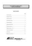
1
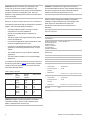
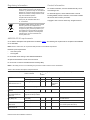
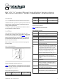
NX-6V2 Control Panel Installation Instructions 500 20 18 Introduction 1000 18 16 This is the NX-6V2-Control Panel Installation Instructions. 1500 16 14 2000 14 12 Installations should only be done by trained professionals. Use this document to install the system with default settings that comply with UL requirements. To install the keypad, other peripherals, and sensors, refer to the documentation for those devices. Terminal descriptions Table 2 describes the panel terminals Table 2: NX-6V2 Terminals Installation There are four slots for board insertions inside the metal enclosure, two on the top and two on the bottom. These allow the PC board to be positioned vertically (Figure 1). When you slide the board between the grooves of the slots, make sure the terminal strip is toward the front opening (toward you) to allow for the wire connections. Note: Install the metal enclosure with the door opening from the top to bottom. Figure 1 Board Installation Terminal Description R1 House telephone ring (grey). R Telephone ring (red). T Telephone tip (green). T1 House telephone tip (brown). EARTH Earth ground. Connect to a cold water pipe or a 6 to 10 ft. driven rod. AC AC input. Connect to a 16.5 V, 40 or 50 VA Class II UL approved transformer. Bell + and If used as a siren output (default), the speaker rating should be 15 watt at 8 or 16 ohm, or 30/40 watt at 4, 8, or 16 ohms. If voltage ouput is selected in location 37, this output becomes voltage output, 12 VDC, 1 Amp maximum load. Note: A 3.3 kohm resistor may be required across the bell terminals when a 12 VDC siren is used. If no resistor is used, you may experience voltage leakage into the siren, which will cause these devices to output a small signal. Bell - KP DATA Connect to the data terminal on the keypads and the expanders. Maximum number of devices is 16 keypads plus 3 other de vices. See Maximum Wire Run table. KP COM Connect to the common terminal on the keypads and the expanders. KP POS Connect to the POS terminal on the keypads and the expanders. Individually, this terminal is limited to 1 amp. Combined, this terminal and AUX PWR+ are limited to 2 amps total current. COM Common negative wire of powered devices such as motion detectors and smoke detectors. AUXPWR + Connect positive wire of all powered devices except smoke detectors and keypads. Individually, this terminal is limited to 1 amp. Combined, this terminal and KP POS are limited to 2 amps total current. NetworX keypad maximum wire run Table 1 lists wire lengths for one keypad at the end of the wire. When connecting more than one keypad to the end of the wire, a higher gauge wire is required Table 1: Maximum keypad wire run Length in feet Wire gauge for NX-6v2 Wire gauge for NX320-E 250 24 22 P/N 466-2338 • REV B • January 2011 1 ZONE 7 Connect to one side of zone 6 loop. Connect the other side to com terminal. Open or short causes alarm. Only zone 6 can be used for a two-wire smoke detector, connected with a 680 ohm EOL resistor. Refer to the wiring diagram. Program location 37, segment 6, option 1. Only zone 6 can be a two-wire zone. NX-1192E COM ZONE 6 NX-1208E 8-zone LED keypad NX-1248E 48-zone LCD keypad NX-1308E 8-zone LED door design keypad NX-1316E 16-zone LED door design keypad Common (-) terminal for zones 5 and 6. NX-1324E 24-zone LED door design keypad Connect to one side of zone 5 loop. Connect the other side to COM terminal. Open or short causes alarm. NX-1448E 48-zone fixed language icon keypad ZONES 1 to 5 Connect as described for zones 5 and 6. AUXOUT 4 Smoke detector power 12 VDC (for those jurisdictions which allow the Priority zone to be used with smoke detectors). Current limited to 250 mA when output is positive and 250 uA when output is negative. This output defaults to Smoke Power, but can be reconfigured. Zone 7 may be used for a 2wire smoke detector using a 680 ohm EOL resistor. (SMOKE +) AUXOUT 1 to 3 192-zone LCD keypad Connect negative lead of low current device [relay, LED (install 1kohm resistor in series with LED), etc.] Connect positive lead of device to COM. Current is limited to 50 mA when output is negative, and 250 uA when output is positive. [1] These products have not been tested and approved by Underwriters Laboratories, In. [2] These wireless devices are UL listed only for residential applications. Note: The NX-6V2 control panel sends a trouble condition once each hour if it senses that no devices have been enrolled. This report shows expander trouble--device zero (0). Control panel programming Programming the control panel requires you to enter program mode, select the module to program, program a location, and then exit the location and program mode. Module list Enter program mode Table 3 shows the modules that are compatible with the NX6V2 system. Additional information and a catalog listing all system components is available from UTC Fire & Security Customer Support. To enter program mode, do the following: 1. Press 8. The five function LEDs (Stay, Chime, Exit, Bypass, and Cancel) begin flashing. 2. Enter the go to program code (default is 9, 7, 1, 3). If the go to program code entry is valid, the Service LED flashes, and the five function LEDs illuminate. You are now in program mode and can select the module to program. Table 3 Modules that can be added to the NX-6V2 Part Description NX-108E 8-zone LED keypad NX-116E 16-zone LED keypad NX-124E 24-zone LED keypad NX-148E Alphanumeric 48-zone LCD keypad NX-148E-RF Alphanumeric 48-zone LCD keypad with built-in 48zone wireless receiver NX-200 Zone doubling kit (includes one hundred 3.74k and one hundred 6.98k resistors) NX-320E Smart power supply and bus extender NX-408E 8-zone wireless expansion module (UL listed part #60-904) NX-416E Program a location 48-zone wireless expansion module (UL listed part #60-904) 1. To access any location, enter the desired programming location, followed by #. If the location is a valid location, the Armed LED extinguishes, the Ready LED illuminates, and the binary data for the first segment of the location is shown by the Zone LEDs. 2. While entering new data, the Ready LED begins flashing to indicate a data change in process. NX-508E Eight-output module NX-534E Two-way listen-in module NX-540E Operator telephone interface module NX-548E 48-zone wireless receiver NX-591EGSM Cell interface 2 Since all modules connected to the NX-6V2 are programmed through the keypad, the module you are programming should be the first entry. To select the module to program, enter 0, #. The 0 is the module number of the control, and # is the entry key. You can find other module entry numbers in the module documentation. Once you enter the module number, the Armed LED illuminates, indicating the keypad is waiting for you to enter a programming location. To program a location, do the following: 16-zone wireless expansion module (UL listed part #60-904) NX-448E Select the module to program NX-6V2 Control Panel Installation Instructions 3. Press to store the newly entered data. The keypad advances to the next segment and displays its data. Repeat this procedure until the last segment is reached. 4. To move to another location after exiting a location (Armed LED illuminated): • Press the Police key for the next sequential location. • Press the Fire key for the previous location. • Press the Medical key for the same location. 5. To review the data in a specific location, repeat the above procedure, pressing but with no numeric data entry. Each time you press , the programming data of the next segment displays. Exit a location To exit the current programming location, do the following: 1. Press the key. The Ready LED goes off and the Armed LED goes on. You must press the key to save the data. 2. To exit before the last segment, press # (Armed LED illuminates). to the data terminal into the NX-6V2 memory. This allows the modules to be supervised by the control panel. To enroll the modules, do the following: 1. Enter program mode and program the desired settings for each module. 2. When you exit program mode, the NX-6V2 automatically enrolls the devices. The enrolling process takes about 12 seconds, during which time the Service LED illuminates. If a speaker is attached to the NX-6V2, it clicks at this time. If a siren or bell is attached to the NX-6V2, it sounds for about one second. If the module is not detected, the Service LED illuminates. Note: User codes are not accepted during the enrolling process. Quick start programming locations For most routine installations, the quick start locations allow you to enable a majority of the options available with the NX6V2 (when communicating in Contact ID or SIA formats). The quick start locations include: You are now ready to enter another programming location. If you attempt to program an invalid entry for a particular segment, the keypad beeps three times indicating an error and remains in that segment awaiting a valid entry. • Location 0 - Phone 1 • Location 1 - Phone 1 account code • Location 2 - Phone 1 communicator format • Location 3 - Phone 1 dial attempts/backup control Exit program mode Location 0 - Phone 1 To exit program mode, do the following: Location 0 has 20 segments of numerical data. Use this location to program phone 1. The default for each segment is 14. 1. When you have completed all programming, press Exit to leave the selected module. 2. If there is another module to be programmed, select it by entering its address, followed by #. The procedure for programming these devices is the same as for the control panel, except the locations are for the module selected. 3. If no additional modules are to be programmed, press Exit again to leave program mode. Loading factory defaults To load factory defaults, enter program mode, enter the device address and number and then enter 9, 1, 0, #. The keypad beeps three times indicating that loading is in progress. The process takes about six seconds. You cannot exit the location until loading is completed. Enrolling modules and keypads The NX-6V2 automatically finds and stores all keypads, zone expanders, wireless receivers, and other modules connected NX-6V2 Control Panel Installation Instructions • To program a delay of four seconds, enter 13 in the appropriate segment. • To program tone dialing, enter 15 in the segment where tone dialing begins. • If the entire number is tone dialing, enter 15 in the first segment. • Enter 11 for a *, and 12 for a #. Location 2 - Phone 1 communicator format Location 2 has one segment of numerical data. Use this location to program the communicator format used to transmit to the receiver connected to phone 1. Refer to your central station receiver documentation to determine which format is compatible. Table 4 describes the formats for this location. If you need a format other than those listed, review the override options described in Loc to build the appropriate format. Program a 15 to create a special format (in addition to the entries in Location 18). The default is 0. If this location contains 3 a 0, the built-in communicator is disabled and the NX-6V2 functions as a local-only control. Location 3 - Phone 1 dial attempts/backup control Table 4 communicator formats Segment 1 - Phone 1 dial attempts Location 3 has two segments of numerical data. Data Format Description 0 Local Communicator is disabled 1 Universal 4+2 Two-digit event code 1800 Hz transmit 2300 Hz handshake double round parity 40 pps [1] 2 3+1 fast (or 4+1) One-digit event code 1900 Hz transmit 1400 Hz handshake double round parity 20 pps Segment 2 - Phone 1 backup control • Program a 0 in segment 2 to cause the NX-6V2 to make the designated number of attempts to phone 2 before setting the fail to communicate condition to stop reporting. • Program a 1 in segment 2 to cause the NX-6V2 to stop trying to communicate after the designated number of attempts have been made to phone 1. • Program a 2 in segment 2 to cause the NX-6V2 to make the dial attempts in increments of two. The first two attempts are made to phone 1, the next two attempts to phone 2. This repeats until the total number of attempts designated in segment 1 is completed. 3 Reserved Reserved 4 Pager Two-digit event code DTMF transmission 5 3/1 or 4/1 slow 1800 Hz transmit 2300 Hz handshake double round parity 20 pps hex capability 6 3/1 or 4/1 slow 1800 Hz transmit 1400 Hz handshake double round parity 20 pps hex capability Program the number of dial attempts (1 to 15) the communicator makes to phone 1 before ending the notification process. The default is 8, which means that the communicator makes eight attempts to the first number. Program the backup control for phone 1. The default is 0. 7 3/1 or 4/1 fast 1800 Hz transmit 2300 Hz handshake double round parity 40 pps hex capability 8 3/1 or 4/1 fast 1800 Hz transmit 1400 Hz handshake double round parity 40 pps hex capability 9 3/1 or 4/1 fast with parity 1800 Hz transmit 2300 Hz handshake single round parity 40 pps hex capability 10 3/1 or 4/1 fast with parity 1800 Hz transmit 1400 Hz handshake single round parity 40 pps hex capability 11 4+2 express Two-digit event code DTMF transmission 12 4+2 fast Two-digit event code 1900 Hz transmit 1400 Hz handshake double round parity 20 pps 13 Ademco contact ID DTMF 14 SIA Frequency shift keys 15 Custom format See Loc Segment 1 16 3/1 or 4/1 slow Same as 5, but sends the alarm event code rather than the zone number 1. Alarms and alarm restores. 17 3/1 or 4/1 slow Same as 6, but sends the alarm event code rather than the zone number 2. Opening and closings. 18 3/1 or 4/1 fast Same as 7, but sends the alarm event code rather than the zone number 19 3/1 or 4/1 fast Same as 8, but sends the alarm event code rather than the zone number 20 3/1 or 4/1 fast with parity Same as 9, but sends the alarm event code rather than the zone number 21 3/1 or 4/1 fast with parity Same as 10, but sends the alarm event code rather than the zone number 22 SIA SIA with area modifiers [1] pulses per second 4 Location 4 - Phone 1 events reported Location 4 has two segments of feature selection data. Use this location to select those events reported to phone 1. • If you do not want dual or split reporting, use Location 4 to select all events to phone 1. • If you want dual or split reporting and the split is based on the event type (alarm, open/close, etc.), use Location 4 to select only those events that are reported to phone 1. • If you don’t want events reported to phone 1, program 0 in Location 4 (disabling all options). 3. Zone bypass and bypass restores. 4. Zone trouble and trouble restores. 5. Power fail, low battery, power restore, and low battery restore. 6. Bell cut, telephone line cut, bell cut restore, telephone line restore. 7. Test reports. 8. Start and end programming, download complete. NX-6V2 Control Panel Installation Instructions Segment 2 Segments 3 and 4 - Reserved 1. Zone and box tamper and tamper restore. 2. Auxiliary power over current, ground fault, and restore for both. 3. Wireless sensor missing and restore. 4. Wireless sensor low battery and restore. 5. Expander trouble and restore. 6. Fail to communicate. 7. Zone activity monitor. Location 25 - Zones 1 to 8 zone type Location 25 has eight segments of numerical data. Use this location to program the zone type for zones 1 to 8. Use segment 1 for zone 1, segment 2 for zone 2, etc. The segment defaults are 3, 5, 6, 6, 6, 6, 6, 6. Zones are programmed to be one of thirty different types. Use zone types 17 through 20 for wireless, or for hardwired zones using European double EOL configuration Table 5 describes the zone types. 8. Reserved Table 5. Zones types Location 18 - Custom communicator format Zone Type Description Location 18 has four segments of feature selection data. Use this location to program the communicator format used to transmit to the receiver connected to phone 3. Refer to your central station receiver documentation to determine which format is compatible. Select a format from Table 4. If you need a format other than those listed, review the override options described in this location to build the appropriate format. 1. Day zones This zone is instant when the system is armed; trouble zone when the system is disarmed. 2. 24-hour audible This zone creates an instant yelping siren alarm regardless of the armed state of the control panel. 3. entry/exit delay A trip starts entry delay 1. The lack of a trip during exit delay enables the automatic bypass or instant mode if programmed. 4. Follower with autobypass disabled This zone is instant when the system is armed and no entry or exit delays are being timed. It is delayed 1 time during entry and exit. This zone does not automatically bypass even if enabled in segment 1. 5. Interior follower with autobypass This zone is instant when the system is armed and no entry or exit delay is being timed. It is delayed 1 time during entry and exit. This zone automatically bypasses if enabled in segment 1. 6. Instant This zone creates an instant alarm whenever it is tripped and the armed LED is on. 7. 24-hour silent This zone creates an instant silent alarm regardless of the armed state of the control panel. It does not display on the keypad. 8. Fire This zone illuminates the fire LED and sounds the temporal siren each time the zone is shorted. The fire LED flashes rapidly indicating a problem if the zone is open. 9. Entry/exit delay 2 A trip starts entry delay 2. The lack of a trip during exit delay enables the automatic bypass or instant mode if programmed. 10. 24-hour silent supervised This zone creates an instant silent alarm regardless of the armed state of the control panel. It displays on the keypad. Segment 1 1. On for 1800 Hz transmit; off for 1900 Hz. 2. On for 2300 Hz handshake; off for 1400 Hz. 3. On for cksum parity; off for double round parity. 4. On for two-digit event code; off for one-digit event code. 5. Reserved. 6. Reserved. 7. On for 20 pps; off for 10 or 40 pps. 8. On for 10 pps; off for 20 or 40 pps. Segment 2 1. On for pager format (no handshake required). 2. On for 1400/2300 handshake. 3. Reserved. 4. Reserved. 5. On for contact ID. 11. Reserved 12. Interior follower with cross zone This zone is instant when the system is armed and no entry or exit delay is being timed. It is delayed during entry and exit delay times. If a cross zone is not being timed, it starts a cross zone timer. If a cross zone is being timed, it creates an instant alarm. This zone automatically bypasses when enabled in segment 1. 13. Instant entry guard This zone creates on instant alarm whenever it is tripped and the stay LED is off. It starts an entry delay type 2 if it is tripped, the system is armed, and the stay LED is on. 6. On for SIA. 7. On for contact ID or 4+3. 8. On for DTMF. NX-6V2 Control Panel Installation Instructions 5 14. Entry/exit delay 1 with group bypass A trip starts entry delay 1. This zone bypasses when the group bypass command is entered at the keypad. The lack of a trip during exit delay enables the automatic bypass or instant mode if programmed. 15. Interior follower with group bypass This zone is instant when the system is armed and no entry or exit delays are being timed. It is delayed during entry/exit delay times. This zone bypasses when the group bypass command is entered at the keypad. This zone automatically bypasses if enabled in segment 1. 16. Instant with group bypass This zone creates an instant alarm whenever it is tripped and the armed LED is on. This zone bypasses when the group bypass command is entered at the keypad. 17. Entry/exit delay 1 with tamper A trip starts entry delay 1. The lack of a trip during exit delay enables the automatic bypass or instant mode if programmed. This zone type is used to enable the tamper on a wireless transmitter. 18. Interior follower with tamper and autobypass This zone is instant when the system is armed and no entry or exit delay is being timed. It is delayed during entry and exit delay times. This zone automatically bypasses if enabled in segment 1. This zone type is used to enable the tamper on a wireless transmitter. 19 Instant with tamper This zone creates an instant alarm whenever it is tripped and the armed LED is on. This zone type is used to enable the tamper on a wireless transmitter. 20. Entry/exit delay 2 with tamper A trip starts entry delay 2. The lack of a trip during exit delay enables the automatic bypass or instant mode if programmed. This zone type is used to enable the tamper on a wireless transmitter. 21. Gas detection This zone creates an instant alarm regardless of the armed state of the control panel. It displays on the keypad and activates the keypad sounder. 29. Interior follower with activity supervision This zone is instant when the system is armed and no entry or exit delay is being timed. It is delayed during entry and exit delay times. It sends a report if the zone activity time is reached without a change of state. This zone automatically bypasses if enabled in segment 1. 30. Entry/exit with activity supervision A trip starts entry delay 1. It sends a report if the zone activity time is reached without a change of state. The lack of a trip during exit delay enables the automatic bypass or instant mode if programmed. Underwriters laboratories information The NetworX NX-6V2 holds the following listings from Underwriters Laboratories (US and Canadian) UL365 Police station connected burglar alarms. UL609, CAN/ULC-S303M91 Mercantile, police station connect with basic line security requires NX-003-C enclosure UL985, CAN/ULC-S545M89 Household fire UL1023, ORDC1023-1974 Household burglary UL1610 Central station burglar alarm unit UL1635 Digital alarm communicator system units UL1637 Home health care signaling When installing an NX-6V2 in compliance with Underwriters Laboratories, the following instructions must be observed: • Initiating and indicating devices must be rated at 11.5 to 12.4 VDC residential, 12.0 VDC commercial. • Force arming and auto arming must not be enabled. • For residential fire applications, the indicating devices shall be a Wheelock 34T-12 or equivalent. • The listen in feature shall not be enabled. • The siren/bell test must be enabled. The auxiliary outputs controlling the audible device require a minimum cutoff time of 15 minutes for commercial burglary, four minutes for residential applications, or 30 minutes for commercial burglary for Canada. • For residential fire installations, the dynamic battery test time cannot exceed four hours. • Ringback must be enabled on UL commercial burglary installations. 22. Low temperature detection This zone creates an instant silent alarm regardless of the armed state of the control panel. It displays on the keypad and activates the keypad sounder. 23. High temperature detection This zone creates an instant silent alarm regardless of the armed state of the control panel. It displays on the keypad and activates the keypad sounder. 24. Manual fire This zone illuminates the fire LED and sounds the temporal siren each time the zone is shorted. It also flashes (rapidly) the fire LED, indicating a problem if the zone is open. 25. Chime only This zone creates no alarm regardless of the armed state of the control panel. It chimes anytime it is faulted and displays on the keypad. Local only. 26. Interior follower delay 2 This zone is instant when the system is armed and no entry or exit delay is being timed. It is delayed 2 times during entry and exit. This zone automatically bypasses if enabled in segment 1. 27. Interior follower force armable This zone is instant when the system is armed and no entry or exit delay is being timed. It is delayed 1 time during entry and exit. This zone automatically bypasses if enabled in segment 1. • On commercial burglary installations, the fire initiating circuits must not be connected. • The entry guard feature must be disabled. A trip starts entry delay 2. The lack of a trip during exit delay enables the automatic bypass or instant mode if programmed. • Group bypassing must be disabled. • Delay before dial seizure must be set to 0. 28. Entry/exit force armable delay 2 6 NX-6V2 Control Panel Installation Instructions • Total current draw from auxiliary power connections at terminal positions POS, AUX PWR, and SMOKE PWR must not exceed 400 mA. • Remote downloading must not be used on UL listed systems. • For residential burglary applications, the maximum entry and exit delay times are 45 and 60 seconds respectively. The exit delay time must not exceed 60 seconds for commercial burglar alarm applications. Additional UL 609 installation requirements The alarm housing for a mercantile alarm system without a remote alarm transmission connection shall be mounted on the outside of the building, visible from a public street or highway. It shall be accessible for examination and repair. It shall also be located not more than four stories above the street level unless: a) A second alarm sounding device and housing, intended for outside service is mounted adjacent to the premises or area of the building in which the alarm system is installed or • The keyswitch option must not be used. • The telephone line monitor must be enabled. • The telephone line cut delay must not exceed 90 seconds. • The 24-hour communicator test transmission is required. • For 24-hours of standby power using a 7.0 Ah battery, limit auxiliary power load to 140 mA. In either case, the outside alarm sounding device and housing may be mounted as high as the seventh floor. • For 24-hours of standby power using a 17.2 Ah battery, limit auxiliary power load to 400 mA. Additional UL 365 installation requirements • The silent keypad option must not be enabled. • UL has only verified compatibility with the following listed DACRs and formats: Sure-Gard SG-MLR2-DG: 2,9,10,12,13,14; Silent Knight 9000 - 2,12; FBI CP220FBI, 13; and Ademco 685: 2,11,12, and 13. • For burglary installations, cross zoned detectors must overlap 100 percent in the area of coverage, and similar coverage areas must be used. For example, interior protection is cross zoned with interior protection, and so on. • Expander trouble must activate the siren. • For UL 1637, expander trouble must activate the keypad sounder. • If the late to close/early to open feature is enabled, the opening and closing reports must be enabled. • For Canadian installations, the class II transformer secure tab must not be employed. • • The four-wire smoke detector employed must be rated to operate over the voltage range of 11.5 to 12.4 V. Compatible listed devices: (special applications): • Bell output (sirens): Wheelock models: NS-1215W, NS- 121575W, NS4-1215W, NS4-121575W, AS-1215W, AS- 121575W • Horn/strobe system sensor: S1224MC strobe series; 1224MC Horn/strobe series; H12/24 Horn series • Smoke output (four-wire detectors): ESL: 500N series; 449CTE series; 521 series; 541 series b) A second alarm sounding device, intended for inside service is mounted within the premises. In a mercantile burglar alarm system, a mercantile alarm sounding device located within a building, but outside the protected area, is acceptable, provided it is rated for outside service and alarm conditions are transmitted to: a) The dispatch location of the law enforcement agency having jurisdiction over the protected property or b) A central station or residential monitoring station complying with the Standard for Central-Station Alarm Services, UL 827. In a mercantile burglar alarm system, an alarm sounding device located within the area of greatest protection, or outside the area of greatest protection but within an area protected by an alarm system and that shares a common control unit with the system installed in the area of greatest protection, is acceptable provided it is rated for inside service and alarm conditions are transmitted to: a) The dispatch location of the law enforcement agency having jurisdiction over the protected property or b) A central station or residential monitoring station complying with the Standard for Central-Station Alarm Services, UL 827. An inside sounding device shall be mounted at least 10 feet (3.05 m) above the floor or at the surface of the ceiling. When there is fixed construction within the area that could provide access for an intruder, the alarm sounding device shall also be mounted at least 4 feet (1.2 m), as measured horizontally, away from the edges of the fixed construction or at least 10 feet (3.05 m) above it so as to minimize access by an intruder. • System sensor models: 2112/24R; 2112/24TR; 2112/24AT; 2112/ATR; 2112/24AITR; 4WTA-B; 4WTR-B; 4WTAR-B; 4WITAR-B • Detection systems: F220-B6C; D273 series; Hochiki: SBC4/12, 4/12W NX-6V2 Control Panel Installation Instructions 7 WARNING: Electrical codes will vary, depending on the country and city where the system is installed. It is the installers responsibility to ensure that the electrical installation is safe and conforms to all applicable codes , laws, and regulations. Only qualified persons should connect this device to the main supply. Minimum system configurations for UL installations The following requirements apply to residential fire, residential burglary, and commercial burglary installations. • The NetworX NX-6V2 panel is necessary to initiate residential and commercial installations. • At least one compatible keypad is needed for all applications. WARNING: If separate power supplies are necessary to accommodate additional devices, safety standards require that each power supply be prominently marked with adequate instructions for removing all power from the unit. Caution: Observe polarity when installing a new battery. Installing the battery backwards may cause damage to the panel. Dispose of used batteries according to the manufacturer’s instructions and/or local government authorities. Specifications Operating power 16.5 VAC 40 or 50 VA transformer Auxiliary power w/25 VA transformer 12 VDC regulated 500 mA • The AD10-12 bell and UL Approved bell-housing shall be used for all applications. • Commercial UL applications require the NX-003-C metal enclosure. Supplied screws to be used. • A minimum of two keypads is required for home health applications, and each keypad must be set to a unique address. • The wireless devices are only UL listed for residential applications. Standard loop Fuse Type T 200 mA 250 VAC • The DACT shall be enabled for all commercial burglary applications. Built-in siren driver Two tone (temporal and yelp) Loop response Selectable 50 mS or 500 mS Operating temperature 32 to 120°F (0 to 49°C) UL requires that an alarm panel work for a minimum amount of time during a power failure. Table 6 lists the battery capacities needed to meet time limits based on the current draw of the panel and all attached devices. Auxiliary power w/40 ro 12 VDC regulated 1 A 50 VA transformer (M G Electronics part number 22-156 for UL or 22-156-CN for Canadian installations) Loop resistance 300 ohms maximum LED keypad • Current draw • 130 mA max. • Zones normal w/o • 55 mA • Dimensions • 6.4 x 4.0 x 1.1 in. (16.3 x 10.2 x 2.8 cm) sounder Table 6. Battery capacities Standby time Total auxiliary current Standby battery capacity Alarm current • Current draw • 110 mA max. 24-Hours 1.9 A 1.25 A 600 mA 51 Ah 34 Ah 17 Ah 600 mA 1A 1A • Zones normal w/o • 75 mA 900 mA 600 mA 300 mA 51 Ah 34 Ah 17 Ah 1A 1A 1A • • 6.4 x 5.3 x 1.0 in. (16.3 x 13.5 x 2.5 cm) Metal enclosure dimension 11.25 x 11.25 x 3.50 in. (28.58 x 28.58 x 8.90 cm) 600 mA 400 mA 200 mA 51 Ah 34 Ah 17 Ah 1A 1A 1A Shipping weight 9 lb. (4.1 kg) 48-Hours 72-Hours LED keypad sounder Dimensions Note: Calculations are based on three 17A batteries. WARNING: Replace only with a Panasonic LC12V4BP or Yuasa NP4-12 battery. There is a risk of explosion if the battery is replaced with an incorrect type. 8 NX-6V2 Control Panel Installation Instructions Regulatory information FCC compliance Contact information This device complies with part 15 of the FCC Rules. Operation is subject to the following two conditions: (1) This device may not cause harmful interference, and (2) this device must accept any interference received, including interference that may cause undesired operation. For contact information, see www.utcfireandsecurity.com or www.interlogix.com. For technical support, Toll-free: 888.437.3287 in the US including Alaska, Hawaii, Puerto Rico, and Canada. Outside the tool-free area: Contact your dealer. Complies with Part 68 FCC Rules. ACTA (FCC) ID: GCQUSA-33408-AL-E Copyright © 2011 UTC Fire & Security. All rights reserved. IC: 1175A-NXV2 2002/96/EC (WEEE directive): Products marked with this symbol cannot be disposed of as unsorted municipal waste in the European Union. For proper recycling, return this product to your local supplier upon the purchase of equivalent new equipment, or dispose of it at designated collection points. For more information see: www.recyclethis.info. ANSI/SIA CP-01 requirements CP-01 feature descriptions and specifications are listed in Table 7. The following are requirements for compliance with ANSI/SIA CP-01 standards. Note: Where a conflict exists, UL requirements take precedence over ANSI/SIA requirements. Minimum system requirements: • One control panel • Two keypads Do not enable remote arming in SIA classified installations. Off premise transmission must be in the SIA format. Do not exceed 1 minute for the abort window and entry delay. Note: A call-waiting cancel on a noncall-waiting line prevents successful connection to the central station Table 7. CP-01 feature descriptions and specifications CP-01 feature description Exit time Progress annunciation / disable for silent exit <1> Feature description as shown in manual Progra m location Seg/op t Default CP-01 required setting Exit 1 delay 24 2 60 45 to 240 seconds Exit 2 delay 24 4 60 45 to 240 seconds Silent keypad option 93 2 All annunciators enabled Allowed (individual keypads may be disabled) Exit time restart (reexit) This feature is not programmable in the panel. Auto stay arm on unvacated premises Auto bypass Exit time and progress annunciation/disable for remote arm This feature is not programmable in the panel. Exit time and progress are always enabled. Enabled (disabled for remote arming) Entry delays <2> Exit 1 delay 30 to 240 seconds 23 24 1/3 1 Enabled Enabled 30 Enabled Exit 2 delay 24 3 30 30 to 240 seconds Abort window - for nonfire zones Dialer delay 40 8 30 Enabled (may be disabled by zone/zone type, but no cancel reports will be sent) Abort window time - for nonfire zones <2> Dialer delay 40 8 30 15 to 45 seconds NX-6V2 Control Panel Installation Instructions 9 Abort annunciation This feature is not programmable in the panel. Flashing cancel LED goes off when disarming. Enabled Cancel annunciation Cancel 23 Enabled Enabled Duress feature Duress 44 Disabled Disabled Cross zoning Two trips on cross zone 37 5/4 Disabled Required Keypad sounds on cross zone trip 39 5 Disabled Zone type characteristic 111 3/4 Disabled Programmable cross zoning time Cross zone time 40 6 5 minutes Swinger shutdown Swinger shutdown count 38 n/a Enabled for 1 For all non fire zones. Shut down at 1 to 2 trips. trip Swinger shutdown disable Swinger shutdown count 38 n/a Enabled for 1 Allowed trip Fire alarm verification Fire alarm verification time 40 9 Disabled Required (depends on panel and sensors) Call waiting cancel Must be programmed as part of the phone number 0 n/a n/a Required (depends on user phone line) Default changes (from prior versions): Recent closing 23 3/7 Enabled 3/6 Exit error 23 3/8 Enabled Power delay 40 3 60 seconds Allowed <1> Refer to your keypad installation manual. <2> Combined abort window time and entry delay must not exceed one minute. 10 NX-6V2 Control Panel Installation Instructions